Faber Camino Pro - 36 SS 1200 cfm Guía de instalación
- Categoría
- Campanas de cocina
- Tipo
- Guía de instalación
Este manual también es adecuado para

Installation Instructions
Use and Care Information
Instructions d'installation
Utilisez et d'entretien
Instrucciones de instalación
Información de uso y cuidado
CAMINO PRO
CAPR36SS600
CAPR36SS1200
CAPR48SS1200

2
READ AND SAVE THESE INSTRUCTIONS BEFORE YOU START
INSTALLING THIS RANGEHOOD
WARNING: - TO REDUCE THE RISK OF A RANGE TOP GREASE FIRE:
a) Never leave surface units unattended at high settings. Boilovers cause smoking and
greasy spillovers that may ignite. Heat oils slowly on low or medium setting.
b)AlwaysturnhoodONwhencookingathighheatorwhenambeingfood(i.e.Crepes
Suzette, Cherries Jubilee, Peppercorn Beef Flambé).
c) Clean ventilating fans frequently. Grease should not be allowed to accumulate on fan
orlter.
d) Use proper pan size. Always use cookware appropriate for the size of the surface element.
WARNING: - TO REDUCE THE RISK OF INJURY TO PERSONS IN THE EVENT OF A
RANGE TOP GREASE FIRE, OBSERVE THE FOLLOWING*:
a)SMOTHERFLAMESwithaclose-ttinglid,cookiesheet,ormetaltray,thenturnofftheburner.
BECAREFULTOPREVENTBURNS.IftheamesdonotgooutimmediatelyEVACUATE
AND CALL THE FIRE DEPARTMENT.
b) NEVER PICK UP A FLAMING PAN - You may be burned.
c) DO NOT USE WATER, including wet dishcloths or towels - a violent steam explosion will
result.
d) Use an extinguisher ONLY if:
1. You know you have a Class ABC extinguisher, and you already know how to operate it.
2. Thereissmallandcontainedintheareawhereitstarted.
3. Theredepartmentisbeingcalled.
4. Youcanghttherewithyourbacktoanexit.
* Based on "Kitchen Firesafety Tips" published by NFPA
WARNING - TO REDUCE THE RISK OF FIRE OR ELECTRIC SHOCK, do not use this
fan with any solid-state speed control device.
WARNING - TO REDUCE THE RISK OF FIRE, ELECTRICAL SHOCK, OR INJURY TO
PERSONS, OBSERVE THE FOLLOWING:
1. Use this unit only in the manner intended by the manufacturer. If you have any
questions, contact the manufacturer.
2. Before servicing or cleaning unit, switch power off at service panel and lock the
service disconnecting means to prevent power from being switched on acciden-
tally. When the service disconnecting means cannot be locked, securely fasten a
prominent warning device, such as a tag, to the service panel.
CAUTION: For General Ventilating Use Only. Do Not Use To Exhaust Hazardous or
Explosive Materials and Vapors.
WARNING - TO REDUCE THE RISK OF FIRE, ELECTRICAL SHOCK, OR INJURY TO
PERSONS, OBSERVE THE FOLLOWING:
1. InstallationWorkAndElectricalWiringMustBeDoneByQualiedPerson(s)InAccor-
dance With All Applicable Codes And Standards, Including Fire-Rated Construction.
2. Sufcientairisneededforpropercombustionandexhaustingofgasesthrough
theue(chimney)offuelburningequipmenttopreventbackdrafting.Followthe
heating equipment manufacturer's guideline and safety standards such as those
publishedbytheNational FireProtectionAssociation(NFPA),andtheAmerican
SocietyforHeating,RefrigerationandAirConditioningEngineers(ASHRAE),and
the local code authorities.

3
ALL WALL AND FLOOR OPENINGS WHERE THE RANGEHOOD IS INSTALLED MUST
BE SEALED.
This rangehood requires at least 24" of clearance between the bottom of the rangehood
and the cooking surface or countertop. This hood has been approved by UL at this distance
from the cooktop.
This minimum clearance may be higher depending on local building codes. For gas cooktops
and combination ranges, a minimum of 30" is recommended and may be required.
Overhead cabinets on both sides of this unit must be a minimum of 18" above the cooking surface
or countertop. Consult the cooktop or range installation instructions given by the manufacturer
before making any cutouts.
MOBILE HOME INSTALLATION The installation of this rangehood must conform to the
Manufactured Home Construction and Safety Standards, Title 24 CFR, Part 3280 (formerly
Federal Standard for Mobile Home Construction and Safety, Title 24, HUD, Part 280). See
Electrical Requirements.
• Venting system MUST terminate outside the home.
• DO NOT terminate the ductwork in an attic or other enclosed space.
• DO NOT use 4" laundry-type wall caps.
• Flexible-type ductwork is not recommended.
• DO NOT obstruct the ow of combustion and ventilation air.
• Failure to follow venting requirements may result in a re.
WARNING
!
VENTING REQUIREMENTS
Determine which venting method is best for your application. Ductwork can extend either through the
wall or the roof.
The length of the ductwork and the number of elbows should be kept to a minimum to provide efcient
performance. The size of the ductwork should be uniform. Do not install two elbows together. Use
duct tape to seal all joints in the ductwork system. Use caulking to seal exterior wall or oor opening
around the cap.
Flexible ductwork is not recommended. Flexible ductwork creates back pressure and air turbulence
that greatly reduces performance.
Make sure there is proper clearance within the wall or oor for exhaust duct before making cutouts.
Do not cut a joist or stud unless absolutely necessary. If a joist or stud must be cut, then a supporting
frame must be constructed.
WARNING - To Reduce The Risk Of Fire, Use Only Metal Ductwork.
CAUTION-Toreduceriskofreandtoproperlyexhaustair,besuretoductairoutside–Do
not vent exhaust air into spaces within walls or ceilings or into attics, crawl spaces, or garages.
3. When cutting or drilling into wall or ceiling, do not damage electrical wiring and
other hidden utilities.
4. Ducted fans must always be vented to the outdoors.

4
• Electrical ground is required on this rangehood.
• If cold water pipe is interrupted by plastic, nonmetallic gaskets or other materials, DO
NOT use for grounding.
• DO NOT ground to a gas pipe.
• DO NOT have a fuse in the neutral or grounding circuit. A fuse in the neutral or
grounding circuit could result in electrical shock.
• Check with a qualied electrician if you are in doubt as to whether the rangehood is
properly grounded.
• Failure to follow electrical requirements may result in a re.
WARNING
!
StateofCaliforniaProposition65Warning(USonly)
WARNING
This product contains chemicals known to the State of California to cause cancer and birth
defects or other reproductive harm.
For more information go to www.P65Warnings.ca.gov
Note: The hood needs to be installed on a separate electrical circuit.

5
1 MOTOR - RANGEHOOD DIMENSIONS 36"
DRAFT 28-NOV-2018 17:42
1 MOTOR RANGEHOOD REAR VENTING

6
2 MOTOR - RANGEHOOD DIMENSIONS 36"
9 13/16”
11 7/16”
11 1/16”
4 15/16”
10" DUCT TRANSITION FOR 2 MOTOR RANGEHOOD 36"
DRAFT 28-NOV-2018 15:53

7
2 MOTOR - RANGEHOOD DIMENSIONS 48"
DRAFT 28-NOV-2018 16:20
9 13/16”
11 7/16”
11 1/16”
4 15/16”
10" DUCT TRANSITION FOR 2 MOTOR RANGEHOOD 48"

8
7
6
9e
8
8
8
7
6
9e
8
8
8
MAIN PARTS 1 MOTOR RANGEHOOD 36"
Components
Ref. Qty. Product Components
1 1 Hood Body, complete with: Controls, Light
6 3 Greaselters
7 6 Filter knobs
8 1 Grease rail
9 1 Recirculation Vent Grill
10 1 Damper ø 5 7/8"
11 1 Blower
Ref. Qty. Installation Components
12a 2 Wall plug
12b 4 Screws 3/16"x1 15/16"
12c 6 Greaseltersscrews(3/16"x3/8")
12e 2 Motorxscrews(3/16"x3/8")
12f 2 Screws 1/8"x 3/8"
(forRecirculationVentGrillmounting)
Qty. Documentation
1 Instruction Manual
MAIN PARTS 2 MOTOR RANGEHOOD 36"
Components
Ref. Qty. Product Components
1 1 Hood Body, complete with: Con trols, Light
2 1 Duct transition
6 3 Greaselters
7 6 Filter knobs
8 1 Grease rail
9 1 Recirculation Vent Grill
10 2 Damper ø 5 7/8"
11 2 Blower
Ref. Qty. Installation Components
12a 2 Wall plug
12b 4 Screws 3/16"x1 15/16"
12c 6 Greaseltersscrews(5/32"x5/16")
12d 4 screws 1/8"x1/4"
12e 4 Motorxscrews(3/16"x3/8")
12f 2 Screws 1/8"x 3/8"
(forRecirculationVentGrillmounting)
Qty. Documentation
1 Instruction Manual
1
12a
12b
7
6
9e
8
8
8
12a
12b
10
10
1
2
12c
12c
12d
12e
12e
9
12f
9
12f
11
11

9
7
6
9e
8
8
8
MAIN PARTS 2 MOTOR RANGEHOOD 48"
Components
Ref. Qty. Product Components
1 1 Hood Body, complete with: Controls, Light
2 1 Duct transition
6 4 Greaselters
7 8 Filter knobs
8 1 Grease rail
9 1 Recirculation Vent Grill
10 2 Damper ø 5 7/8"
11 2 Blower
Ref. Qty. Installation Components
12a 2 Wall plug
12b 4 Screws 3/16"x1 15/16"
12c 8 Greaseltersscrews(5/32"x5/16")
12d 4 screws 1/8"x1/4"
12e 4 Motorxscrews(3/16"x3/8")
12f 2 Screws 1/8"x 3/8"
(forRecirculationVentGrillmounting)
Qty. Documentation
1 Instruction Manual
7
6
9e
8
8
8
12a
12b
10
1
2
12c
12d
7
6
9e
8
8
8
12e
7
6
9e
8
8
8
9
12f
11

10
AVAILABLE ACCESSORIES
PARTS NEEDED
6" Round Metal Ductwork
Telescopic Chimney Duct Cover:
- sku#: CHIM3448 (Use with 48" Camino Pro)
- sku#: CHIM2224 (Use with 36" Camino Pro)
- sku#: CHIM2248 (Use with 36" Camino Pro)
- sku#: CHIM3424 (Use with 48" Camino Pro)
CFM Reducer Accessory Kit sku#: CFMRED
CFM Reducer Accessory Kit sku#: CFMRED-2
Activated Charcoal Filter sku #: FILTER1
Charcoal Filter Kit Washable Long Lasting sku#: FILTER1LL
Min. 24" Min. 30"

11
6"
Rear
1 MOTOR RANGEHOOD REAR INFORMATION
Only for the rst installation
For a rear ducting installation
the blower bracket needs to be
unsecured by rst removing the 12
screws as shown.
Once the screws are removed,
extract it from the body of the Hood
and position it so the transition
opening is facing to the rear wall
(from the back remove and rotate
180 degrees to the left, and then ip
it back 90 degrees as shown in the
diagram).
Once the blower bracket is in place
reinstall the 12 screws to fasten the
bracket to the Hood body.
1
1 MOTOR RANGEHOOD REAR DUCTED INSTALLATION
180°
90°

12
Install the motor into the upper of the hood using
the 2 screws 12e supplied.
Put the motor in the hood body.
2 3
4
9 hole end
Connect the wire cable 9 hole end to the
motor.
180°
90°

13
1 MOTOR RANGEHOOD TOP DUCTED INSTALLATION
1 2
Install the motor into the rear of the hood using
the 2 screws 12e supplied.
Put the motor in the hood body.
3
9 hole end
Connect the wire cable 9 hole end to the
motor.

14
Install the 2 motors into the sides of the blower bracket using the 4 screws 12e supplied.
Put the 2 motors in the hood body. Inside the hood there is a blower bracket divider and the
motors will be one a side.
1
2
Version 07/11 - Page 9
INSTALLATION WITH IB1200 INTERNAL BLOWER (1200 cfm)
1. Install the Plate B (FIGURE 14) which came with the internal
blower kit, on top of the rangehood with the holes located closer to
the front. Use 9 screws supplied with the blower kit
2. Remove the white plastic covering and Install the 4 side trim
pieces to the outside of the hood using (16) part 9b screws, see
the side rail installation in (FIGURE 15).
3. Attach the blower bracket divider inside the hood, with the 2
screws into the top of the hood and 2 screws into the back, all
supplied with the blower kit (FIGURE 16)
FIGURE 16
FIGURE 17
4. Install the 2 motor kits into the sides of the blower bracket using
the 4 screws supplied with the motor kit. (FIGURE 17)
5. Connect the wire (FIGURE 18) that comes with the motor kit
from the side of the two motors to the connection on the inside
of the light panel in the hood. The two - 9 hole ends of the wire
are installed in the two motors, the 6 hole end is connected to
the light panel (FIGURE 11 on the previous page)
FIGURE 15
FIGURE 18
FIGURE 19
6. Install the 2 dampers on top of the hood. If you want one 10"
round duct to come out of the top of the hood, use the transition
piece (FIGURE 19) that comes with the motor kit and install with
four screws. If you want to use 2 seperate 6" round ducts, do not
use the transition.
7. Attach the hood to the cabinet using (12) 9c. screws to the
cabinet. FIGURE 20
8. Follow steps 6 - 9 on the previous page to connect ducting,
wiring, and test the electrical connection.
FIGURE 14
FIGURE 20
B
3
9 hole end
Connect the wire cable 9 hole end to the
left motor and the other wire cable 9 hole
end to the right motor.
9 hole end
9 hole end
2 MOTOR RANGEHOOD TOP DUCTED INSTALLATION

15
Install Damper that is included with the
Hood before connecting to the ductwork.
One for 1 motor model.
Two for 2 motor model.
H
I
H
I
H
I
INSTALLATION INSTRUCTIONS
==
Installation Instruction for Mounting on the Wall
Draw a vertical line on the supporting wall as high as practical, at the center of the area in which
the hood will be installed.
Draw a horizontal line at where the bottom edge of the hood will be located as indicated in the
gure that is a minimum of 24" or 30" above cooking surface.
1
Min. 24" Min. 30"

16
Ø 1/2”
x2
x2
24”
L
16 1/2”
30”
L = 19 11/16”
36”
Ø 1/2”
x2
x2
24”
L
16 1/2”
30”
36” - 48”
L = 19 11/16”
36”
L = 31 1/8”
48”
2.a
Mark the wall where indicated, 16 1/2" above the horizontal line and at L distance on the left and right
of vertical line. The distance L changes for all dimension of Hood.
Insert the two wall plugs 12a in the holes as shown and x them.
Installation for 1 Motor Rangehood
For a different type of Wall, it's
possible to use only the bracket by
remove the plug and the screw from
the plug 12a.
Combine the bracket with specic
wall plug or screw.

17
Ø 1/2”
x2
x2
24”
L
16 1/2”
30”
L = 19 11/16”
36”
Ø 1/2”
x2
x2
24”
L
16 1/2”
30”
36” - 48”
L = 19 11/16”
36”
L = 31 1/8”
48”
2.b
Installation for 2 Motor Rangehood
Mark the wall where indicated, 16 1/2" above the horizontal line and at L distance on the left and right
of vertical line. The distance L changes for all dimension of Hood.
Insert the two wall plugs 12a in the holes as shown and x them.
For a different type of Wall, it's
possible to use only the bracket by
remove the plug and the screw from
the plug 12a.
Combine the bracket with specic
wall plug or screw.

18
Ø 5/16”
x4
x4
x4
Hook the hood body onto the wall plugs 12a. Use a level to insure that Fixing Bracket is level
by adjusting the screws as shown in the picture.
Mark the wall where indicated.
Drill directly into ø 5/16" holes at all the center points marked.
Insert the purchased wall plugs in the holes.
Using thhe remaining screws to anchor the hood in holes.
If installation uses the telescopic chimney extension, refer to the installation manual included in
the Chimney Kit (CHIM3448 - CHIM2224 - CHIM2248 - CHIM3424)
11b
3
4
5

19
1 AND 2 MOTORS DUCTING METHODS 6"
Install Roof or Wall Cap purchased separately. Connect the 6" metal ductwork to the Roof or Wall Cap and
then attach ductwork.
1 AND 2 MOTORS STANDARD DUCTING METHODS
Vertical
Horizontal
Rear
(Validfor1
motor range-
hood only)

20
2 MOTORS DUCTING METHODS 10"
Install Roof or Wall Cap purchased separately. Connect the 10" metal ductwork to the Roof or Wall Cap
and then attach ductwork.
Fix the Duct transition in the hood body with
4 screws 12d.

21
Required Activated Charcoal Filter
Accessory - sku #: FILTER1
Long Lasting Activated Charcoal Filter
Accessory - sku #: FILTER1LL
(purchased separately)
Non Ducted - Recirculation Option
For Non-Ducted Recirculation venting route the ductwork to a location above the hood
where the discharge is vented back into the room.
Use the included Recirculation Vent Grill (9) to cover the opening. Secure the grill with the
2 screws (12f) provided in the Install Kit.
If the directional grille is not used, t a straight tube at least 15" in length from the hood air
outlet to the wall unit.
´
9
12f

22
This page needs to be inserted
after Page 9 and before Page 10
Add the new
kit
:DUCTGRT42
–(42“)
RECIRCULATION INSTRUCTIONS
This page needs to be inserted
after Page 9 and before Page 10
Add the new
kit
:DUCTGRT42
–(42“)
Note: It is recommended that pro-
fessional style cooking always be
vented to the outside; for recirculat-
ing installations, some duct work is
required to exhaust the unit out of
the cabinet.
Note: recommended for 600 CFM
version only
RECIRCULATING INSTALLATIONS
For recirculating installations, Charcoal Filters are necessary. Remove all grease lters
and set aside. Attach one charcoal lter to each end of the blower. Each charcoal lter
attaches to the grid on the side of the blower. Rotate the lter clockwise to install and
counterclockwise to remove (FIGURE 3C). Replace all grease lters.
Some duct work must be installed to exhaust the rangehood back into the kitchen, either
at the top of the cabinet (FIGURE 3A) or at the face or side of the soft (FIGURE 3B).
Install at least 15" of metal duct (g.3A and 3B) at the air exit. Run the duct vertically and
secure it at the opening cut out at the top or side of the cabinet or soft. Installation
upper
cabinet
upper
cabinet
rangehood rangehood
open space
enclosed soft
cooking surface cooking surface
Required Activated Charcoal Filter Accessory - sku
# - FILTER1
Long Lasting Activated Charcoal Filter Accessory -
sku # FILTER1LL
(purchased separately)

23
6
8
Hook the Grease rail (8) positioning it inside
the hood. It is possible to wash and reposition
the rail inside the hood.
7
Installation of wiring connection
Switch off the dedicated power supply to the
hood.
Remove the wiring electrical knockout using a
at-blade screwdriver. Feed the Power Supply
Cable through the electrical knockout.
Connect the Power Supply Cable to the ran-
gehood. Attach the White lead of the power
supply (A) to the White lead of the rangehood
(D) with a twist-on type wire connector. Attach
the Black lead of the power supply to the Black
lead of the rangehood (B) with a twist-on type
wire connector (C). Connect the Green (E)
(Green and Yellow) ground wire under the
Green grounding screw.
Replace the eld wiring compartment cover
and the grease lters.
Connect the ductwork to the damper and seal
all connections with duct tape.
Turn the power supply on. Turn on the blower
and light. If the rangehood does not operate,
check that the circuit breaker is not tripped
or the house fuse blown. If the unit still does
not operate, disconnect the power supply and
check that the wiring connections have been
made properly.
Reattach the eld wiring compartment cover.
Hood wiring

24
8
Before installing the lters (6), tighten the 2 knobs (7) with 2 screws (12c).
Use two hands to insert and remove the lters.
The 36" hood has 3 Filters.
The 48" hood has 4 Filters.
9e
7
6
9e
7
INSTALLATION CONTINUED
Optional Telescopic Chimney Extension Installation
Refer to Instructions inthe Chimney Duct Ccover Accessories.
12c
12c
1
2

25
USE AND CARE INFORMATION
Rangehood Control Panel
The control panel is located in the center of the hood bottom.
Warning: Do NOT force the control dial to turn beyond its limit.
Function Operation LED Color / Light Pattern
Lights - Dimmer Pressthebuttononcetoturnthelightsondimmer(B2)
Lights - High Pressthebuttonasecondtimetoturnthelightsonhigh(B2)
Lights - Off Pressthebuttonathirdtimetoturnthelightsoff(B2)
Speed 1 Quickturnoftheknobtotheright(1sttime)(B1) Green - Solid
Speed 2 Quickturnoftheknobtotheright(2ndtime)(B1) Yellow - Solid
Speed 3 Quickturnoftheknobtotheright(3rdtime)(B1) Red - Solid
IntensiveSpeed(motor
turns off after 10
minutesofoperation)
Quickturnoftheknobtotheright(4thtime)(B1) Red - Blinking
Turn the motor off
While at any speed, hold the knob for 2 seconds to the left to
turn the motor off. Alternatively, a quick turn of the knob to the
leftbackwardsthruthespeeds(1turntotheleftpastspeed
1),turnsthemotoroff.(B0)
No Color
Delay auto shut off
Hold the knob to the right for 2 seconds. The hood and lights
stayonfor10minutes,thenturnoff.(B1)
The selected speed blinks
Heat Sensor Active Pressbuttonfor2seconds(B2) Red Blinking One time
Heat Sensor Inactive Pressbuttonfor2seconds(B2) Red Blinking Three times
Heat Sensor Fault Purple blinking
Heat Sensor Features
If the motor is off and the temperature gets to approximately
130degreesF(55degreesC°)–theblowerturnsonspeed
2 for a minimum of 15 minutes. Once the temperature has
droppedbelow130degreesF(55degreesC°),themotor
turns off. If you operate the hood manually during this
function, the auto on sensor is disabled for 15 minutes.
Red - Blinking
Heat Sensor Faults
If the temperature remains too high, the blower remains on
for up to 90 minutes until the temperature has dropped below
130degreesF(55degreesC°).
Red - Blinking
B0 B1
B2

26
Lighting unit
• Remove the snap-on lamp cover
by levering it from under the metal
ring, supporting it with one hand.
• Replace the lamp with a new one
of the same type, making sure that
you insert the two pins properly into
the housings on the lamp holder.
• Replace the snap-on lamp cover.
Gu10 self-ballasted led
lamps – listed in ac-
cordance with
ul 1993/nmx-
j-578/1-ance/
csa c22.2 No.
1993
Cleaningmetalgreaselters
The metal grease lters can be cleaned in hot detergent
solution or washed in the dishwasher. They should be
cleaned every 2 months, or more frequently if use is
particularly heavy.
• Install the grease rail into the back of the hood, into
the slots on the inside oor of the rear of the hood
• The grease lters should be installed before operating
the rangehood.
• To install the lters, use the two knobs to hold the lter
and insert the lter into the front edge of the hood
with the knobs facing out into the spring loaded slot.
Install the other end of the lter above the grease rail
in the back of the hood.
• No water can be present in lters before installing
back in hood.
Replacing Activated Charcoal Filter
The Activated Charcoal Filters are not washable
and cannot be regenerated, and should be replaced
approximately every 4 months of operation, or more
frequently with heavy usage.
• Remove the charcoal lter by rotating it clockwise (
backwards) until it unlocks from the motor housing and
pull off sideways.
• To re-insert each charcoal lter, place up against
the side of the blower and push it inward. Then
turn the charcoal lter clockwise (forward) until it
ts into place.
Caution: "When used in recirculation mode, to
Reduce the Risk of Fire and Shock use only conver-
sion kit Model FILTER 1 or FILTER1LL".
1
2

27
Wiring Diagram
Dolce, Corrado
19-Dec-2018
Released
0 1 2 3 4 5 6 7 8 9
H90_559
01
Drawing N : Rev :
Modif. by
These drawings and specifications are the property of Franke Technology and
Trademartk Ltd and shall not be reproduced.copied or trasferred to any third party
without the prior written permission of Franke Tecnology and Trandemark Ltd.
Switzerland.It is strictly prohibited to get quotes from the drawing or bring
modifications without the prior written conset of franke Techology and Trademark
Doc.status
Approved date
Modification description
Approved by
WIRING DIAGRAM M8-4V ATF SENSOR GU10 LED
Denomination
Doc Type
Creation date
19.Dic.2018
DOLCE CORRADO
Created by
991.0573.191
Code
SENSOR
BLK
M8-4V
BRW
ORG
M1
GRY
RED
(YELL)
WHT
BLU
BLK
M8-4V
BRW
ORG
M1
GRY
RED
(YELL)
WHT
BLU
BLK
YEL
7
BLK
MOTOR
6
GRY
5
WHT
4
BLU
3
PNK
2
L-B
WIRING
BOX
1
BRW
Y-G
LUX2
WHT
2
LINE
120Vac 60Hz
1
FLAT CABLE
BLK
AUX
2
Y-G
Faber ATF
1
line filter
LUX1
2
ORG(red)
1
ORG(vlt)
FLAT CABLE
LED LED LED LED

28
January 4, 2016
FABER CONSUMER WARRANTY & SERVICE
All Faber products are warranted against any defect in materials or workmanship for the original purchaser
for a period of 1 year from the date of original purchase (requires proof of purchase). This warranty covers
labor and replacement parts. Faber, at its option, may repair or replace the product or components
necessary to restore the product to good working condition. To obtain warranty service, contact the dealer
from whom you purchased the range hood, or the local Faber distributor. If you cannot identify a local Faber
distributor, contact us at (508) 358-5353 for the name of a distributor in your area.
The following is not covered by Faber's warranty:
1. Service calls to correct the installation of your range hood, to instruct you how to use your range hood, to
replace or repair house fuses or to correct house wiring or plumbing.
2. Service calls to repair or replace range hood light bulbs, fuses or filters. Those consumable parts are
excluded from warranty coverage.
3. Repairs when your range hood is used for other than normal, single-family household use.
4. Damage resulting from accident, alteration, misuse, abuse, fire, flood, acts of God, improper installation,
installation not in accordance with electrical or plumbing codes or Faber documentation, or use of products
not approved by Faber.
5. Replacement parts or repair labor costs for units operated outside the United States or Canada, including
any non-UL or C-UL approved Faber range hoods.
6. Repairs to the hood resulting from unauthorized modifications made to the range hood.
7. Expenses for travel and transportation for product service in remote locations and pickup and delivery
charges. Faber range hoods should be serviced in the home.
THIS WARRANTY DOES NOT ALLOW RECOVERY OF INCIDENTAL OR CONSEQUENTIAL DAMAGES, INCLUDING, WITHOUT
LIMITATION, DIRECT, INDIRECT, INCIDENTAL, SPECIAL OR CONSEQUENTIAL DAMAGES, PERSONAL INJURY/WRONGFUL
DEATH OR LOST PROFITS FABER WARRANTY IS LIMITED TO THE ABOVE CONDITIONS AND TO THE WARRANTY PERIOD
SPECIFIED HEREIN AND IS EXCLUSIVE. EXCEPT AS EXPRESSLY SPECIFIED IN THIS AGREEMENT, FABER DISCLAIMS ALL
EXPRESS OR IMPLIED CONDITIONS, REPRESENTATIONS, AND WARRANTIES INCLUDING, WITHOUT LIMITATION, ANY
IMPLIED WARRANTIES OF MERCHANTABILITY OR FITNESS FOR A PARTICULAR PURPOSE
.
This warranty gives you specific legal rights that may vary from state to state.
Model#: ______________________________ Serial #: _____________________________

29
VEUILLEZ LIRE ET CONSERVER LA PRÉSENTE NOTICE AVANT DE
COMMENCER L'INSTALLATION DE LA HOTTE DE CUISINE
AVERTISSEMENT:-POUR RÉDUIRE LE RISQUE D'UN FEU DE GRAISSE SUR LA TABLE DE
CUISSON:
a) Ne laissez jamais sans surveillance les éléments de la surface de cuisson à température élevée.
Les bouillonnements excessifs peuvent provoquer de la fumée et les débordements de graisse
peuvents'enammer.L'huiledoitêtrechaufféelentement,àunetempératurebasseoumoyenne.
b) Assurez-vous de toujours mettre en marche le ventilateur de la hotte lorsque vous cuisinez
àtempératureélevéeoupréparezunmetsambé(p.ex.crêpesSuzette,cerisesjubilé,bœuf
ambé).
c) Nettoyez régulièrement les ventilateurs d'aspiration. Assurez-vous de ne pas laisser de la graisse
s'accumulersurleventilateurouleltre.
d)Utiliseztoujoursdespoêlesetcasserolesdelatailleappropriée.Utiliseztoujoursdesustensiles
de cuisine de la taille adaptée à celle de l'élément chauffant.
AVERTISSEMENT:-POURPRÉVENIRLESBLESSURESENCASDEFEUDEGRAISSESURLA
TABLEDECUISSON,SUIVEZLESRECOMMANDATIONSSUIVANTES*:
a) ÉTOUFFEZ LES FLAMMES à l'aide d'un couvercle hermétique, d'une plaque à biscuits ou d'un
plateau métallique, puis éteignez le brûleur. FAITES ATTENTION AUX BRÛLURES. Si le feu ne
s'éteint pas immédiatement, QUITTEZ LES LIEUX ET APPELEZ LES POMPIERS.
b) NE PRENEZ JAMAIS UNE CASSEROLE EN FLAMME - Vous pourriez vous brûler.
c) N'UTILISEZ JAMAIS DE L'EAU, ni un linge à vaisselle ou un torchon mouillé, pour éteindre le feu.
Cela pourrait provoquer une violente explosion de vapeur.
d)UtilisezunextincteurUNIQUEMENTsi:
1. Vousêtescertainqu'ils'agitd'unextincteurdeclasseABCetquevousconnaissezbienson
mode d'emploi.
2. Le feu est de faible intensité et se limite à l'endroit où il a démarré.
3. Les pompiers ont déjà été appelés.
4. Unevoiedesortiesetrouvederrièrevouspendantquevouséteignezlesammes
* D'après le guide «Kitchen Firesafety Tips» publié par la NFPA aux États-Unis
AVERTISSEMENT - POUR RÉDUIRE LE RISQUE D'INCENDIE OU DE CHOC ÉLECTRIQUE, n'utilisez
jamais ce ventilateur en association avec un dispositif de réglage de vitesse à semi-conducteurs.
AVERTISSEMENT - POUR RÉDUIRE LES RISQUES D'INCENDIE, DE CHOC ÉLECTRIQUE OU DE
BLESSURECORPORELLE,RESPECTEZLESINSTRUCTIONSSUIVANTES:
1. Utilisez cet appareil uniquement de la façon prévue par le fabricant. Pour toute question, com-
muniquez avec le fabricant.
2. Avant de procéder à l'entretien ou au nettoyage de l'appareil, coupez l'alimentation au niveau du
panneau électrique et verrouillez-le pour vous assurer que l'électricité n'est pas rétablie accidentel-
lement.S'iln'estpaspossibledeverrouillerledispositifd'interruptiondel'alimentation,afchezde
façon ferme et bien visible un avis de danger, par exemple à l'aide d'une étiquette sur le panneau.
ATTENTION:Destinéàunusagedeventilationgénéraleuniquement.N'utilisezpascedispositif
pour l'aspiration de vapeurs ou de matériaux dangereux ou explosifs.
AVERTISSEMENT - POUR RÉDUIRE LES RISQUES D'INCENDIE, DE CHOC ÉLECTRIQUE OU DE
BLESSURECORPORELLE,RESPECTEZLESINSTRUCTIONSSUIVANTES:
1. L'installationetlebranchement électriquedoiventêtreréalisésparun technicienqualiéet
conformément à tous les codes et normes en vigueur, incluant ceux concernant la construction
à l'épreuve du feu.
2. Andegarantirunecombustionetuneévacuationadéquatesdesgazparlesconduitesdela
cheminée des appareils à combustion, une bonne aération est nécessaire pour éviter le refou-
lement. Respectez les lignes directrices fournies par le fabricant du matériel chauffant, ainsi que
lesnormesdesécuritécommecellespubliéesparlaNationalFireProtectionAssociation(NFPA)
etlaAmericanSocietyforHeating,RefrigerationandAirConditioningEngineers(ASHRAE)aux
États-Unis, ainsi que les codes en vigueur dans votre région.

30
TOUTE OUVERTURE DANS LE MUR OU LE PLANCHER À PROXIMITÉ DE LA
HOTTE DOIT ÊTRE SCELLÉE.
Un espace libre d'au moins 24" est requis entre le bas de la hotte et la surface de cuisson
ou le comptoir. Cette hotte a été homologuée par l'UL à cette distance de la surface de cuisson.
L’espace libre minimal requis peut-être plus grand, selon la réglementation en matière de
construction de votre région. Pour les cuisinières à gaz et les cuisinières combinées, un
espace minimal de 30" est recommandé et pourrait être exigé.
Les armoires suspendues de chaque côté de l'appareil doivent se trouver à au moins 18"
de la surface de cuisson ou du comptoir. Consultez la notice d'installation de la surface de
cuisson ou de la cuisinière fournie par le fabricant avant de pratiquer des ouvertures.
INSTALLATION DANS UNE MAISON MOBILE L'installation de cette hotte doit être conforme
à la Partie 3280 de la norme Manufactured Home Construction and Safety Standards, Title 24
CFR (précédemment la partie 280 de la norme Federal Standard for Mobile Home Construction
and Safety, Title 24, HUD). Consultez la che technique électrique.
CRITÈRES DE VENTILATION
Déterminez quelle méthode de ventilation est mieux adaptée à votre application. Les conduits peuvent
passer par le mur ou le toit.
Pour garantir une meilleure efcacité, la longueur des conduits et le nombre de coudes doivent être le plus
limités que possible. Le diamètre des conduits devrait être uniforme. N'installez pas deux coudes ensemble.
Utilisez un ruban pour canalisations an de sceller tous les joints du système de conduits. Utilisez un calfeu-
trage pour sceller les ouvertures dans le mur extérieur ou le plancher, autour du clapet.
Il n'est pas recommandé d'utiliser des conduits flexibles. Les conduits flexibles provoquent une contre-pression
et de la turbulence qui diminuent grandement l'efficacité de l'appareil.
Assurez-vous que l'espace libre dans le mur ou le plancher est sufsant pour le conduit d'évacuation avant de
pratiquer les ouvertures. Ne coupez jamais une poutre ou un chevron, sauf si c'est absolument nécessaire.
S'il s'avère nécessaire de couper une poutre ou un chevron, la construction d'un renforcement est requise.
AVERTISSEMENT - Pour réduire le risque d'incendie, utilisez uniquement des conduits métalliques.
ATTENTION - Pour réduire le risque d'incendie et pour évacuer adéquatement l'air, assurez-vous
deraccorderlesconduitsàl'extérieur–Nediffusezpasl'aird'évacuationdansdesespacesà
l'intérieur des murs ou du plafond, ou encore à l'intérieur d'un grenier, d'une galerie technique
ou d'un garage.
3. Lorsque vous faites une ouverture ou percez dans un mur ou le plafond, veillez à ne pas en-
dommagerleslsélectriquesoud'autresdispositifscachés.
4. Lesventilateurscanalisésdoiventtoujoursêtreraccordésàl'extérieur.
• Le système de ventilation DOIT déboucher à l'extérieur.
• NE FAITES PAS déboucher les conduits dans un grenier ou un autre endroit fermé.
• N'UTILISEZ PAS un clapet de sécheuse mural de 4po.
• Il n'est pas recommandé d'utiliser des conduits exibles.
• N'ENTRAVEZ PAS le ux de l'air de combustion et de ventilation.
• Le non-respect des exigences en matière de ventilation pourrait entraîner un incendie.
AVERTISSEMENT
!

31
Remarque:Lahottedoitêtreinstalléesuruncircuitélectriqueséparé.
• Une mise à la terre électrique est requise pour cette hotte.
• N'UTILISEZ PAS un tuyau d'eau froide pour la mise à la terre si celui-ci est branché par des
joints en plastique, par des rondelles non métalliques ou d'autres matériaux.
• N'UTILISEZ PAS une conduite de gaz pour la mise à la terre.
• N'INSTALLEZ PAS un fusible sur le circuit neutre ou le circuit de mise à la terre. La présence
d'un fusible dans le circuit neutre ou de mise à la terre peut entraîner un choc électrique.
• Consultez un électricien qualié si vous n'êtes pas certain de la mise à la terre de la hotte.
• Le non-respect des exigences de la che technique électrique pourrait entraîner un incendie.
AVERTISSEMENT
!
Avertissementdelaproposition65del'ÉtatdeCalifornie(USseulement)
ATTENTION
Ce produit contient des produits chimiques connus de l'État de Californie pour causer le
cancer et des malformations congénitales ou d'autres problèmes de reproduction.
Pour plus d'informations, visitez www.P65Warnings.ca.gov

32
1 MOTEUR - DIMENSIONS DE LA HOTTE 36"
DRAFT 28-NOV-2018 17:42
1 MOTEUR - VENTILATION ARRIÈRE DE LA HOTTE

33
2 MOTEURS - DIMENSIONS DE LA HOTTE 36"
9 13/16”
11 7/16”
11 1/16”
4 15/16”
PIÈCE DE TRANSITION DU CONDUIT 10" POUR HOTTE 2 MOTEURS 36"
DRAFT 28-NOV-2018 15:53

34
2 MOTEURS - DIMENSIONS DE LA HOTTE 48"
DRAFT 28-NOV-2018 16:20
9 13/16”
11 7/16”
11 1/16”
4 15/16”
PIÈCE DE TRANSITION DU CONDUIT 10" POUR HOTTE 2 MOTEURS 48"

35
7
6
9e
8
8
8
7
6
9e
8
8
8
PIÈCES PRINCIPALES - HOTTE 1 MOTEUR 36’’
PIÈCES PRINCIPALES - HOTTE 2 MOTEURS 36’’
1
12a
12b
7
6
9e
8
8
8
12a
12b
10
10
1
2
12c
12c
12d
12e
12e
9
12f
9
12f
11
11
Composants
Réf. Qté Composants du produit
1 1 Bâti de la hotte, avec : Interrupteurs, éclairage
6 3 Filtres à graisse
7 6 Boutonsdesltres
8 1 Gouttière
9 1 Grille d’évent de recyclage
10 1 Registre ø 5 7/8"
11 1 Ventilateur
Réf. Qté Composants d’installation
12a 2 Chevilles
12b 4 Vis 3/16" x1 15/16"
12c 6 Visdesltresàgraisse(3/16"x3/8")
12e 2 Visdexationdemoteur(3/16"x3/8")
12f 2 Vis1/8"x3/8"(pourlemontagedelagrille
d’éventderecyclage)
Qté Documentation
1 Mode d’emploi
Composants
Réf. Qté Composants du produit
1 1 Bâti de la hotte, avec : Interrupteurs, éclairage
2 1 Pièce de transition du conduit
6 3 Filtres à graisse
7 6 Boutonsdeltre
8 1 Gouttière
9 1 Grille d’évent de recyclage
10 2 Registres ø 5 7/8"
11 2 Ventilateurs
Réf. Qté Composants d’installation
12a 2 Chevilles
12b 4 Vis 3/16"x1 15/16"
12c 6 Visdeltresàgraisse(5/32"x5/16")
12d 4 Vis 1/8" x 1/4"
12e 4 Visdexationdemoteur(3/16"x3/8")
12f 2 Vis1/8"x3/8"(pourlemontagedelagrille
d’éventderecyclage)
Qté Documentation
1 Mode d’emploi

36
7
6
9e
8
8
8
PIÈCES PRINCIPALES - HOTTE 2 MOTEURS 48’’
7
6
9e
8
8
8
12a
12b
10
1
2
12c
12d
7
6
9e
8
8
8
12e
7
6
9e
8
8
8
9
12f
11
PIÈCES PRINCIPALES - HOTTE 2 MOTEURS 48’’
Composants
Réf. Qté Composants du produit
1 1 Bâti de la hotte, avec : Interrupteurs, éclairage
2 1 Pièce de transition du conduit
6 4 Filtres à graisse
7 8 Boutonsdeltre
8 1 Gouttière
9 1 Grille d’évent de recyclage
10 2 Registres ø 5 7/8"
11 2 Ventilateurs
Réf. Qté Composants d’installation
12a 2 Chevilles
12b 4 Vis 3/16"x1 15/16"
12c 8 Visdesltresàgraisse(5/32"x5/16")
12d 4 Vis 1/8" x 1/4"
12e 4 Visdexationdemoteur(3/16"x3/8")
12f 2 Vis1/8"x3/8"(pourlemontagedelagrille
d’éventderecyclage)
Qté Documentation
1 Mode d’emploi

37
ACCESSOIRES DISPONIBLES
PIÈCES REQUISES
Conduit métallique 6" circulaire
Recouvrement de canalisation de cheminée télescopique :
- No d’article : CHIM3448 (à utiliser avec Camino Pro 48")
- No d’article : CHIM2224 (à utiliser avec Camino Pro 36")
- No d’article : CHIM2248 (à utiliser avec Camino Pro 36")
- No d’article : CHIM3424 (à utiliser avec Camino Pro 48")
Réducteur de débit accessoire, numéro d’article : CFMRED
Réducteur de débit accessoire, numéro d’article : CFMRED-2
Filtre à charbon actif, numéro d’article : FILTER1
Filtre à charbon lavable longue durée, numéro d’article : FILTER1LL
Min. 24" Min. 30"

38
6"
Arrière
INFORMATIONS - ARRIÈRE HOTTE 1 MOTEUR
Seulement pour la première
installation
Pour l’installation avec canalisation
arrière, le support du ventilateur doit
d’abord être détaché. Pour ce faire,
retirez les 12 vis comme illustré.
Lorsque les vis sont enlevées,
dégagez le support du bâti de la
hotte et placez-le de façon à ce que
l’ouverture de passage de l’air se
trouve face au mur arrière (dégagez-
le de l’arrière et faites-le tourner de
180 degrés vers la gauche, puis
inclinez-le de 90 degrés vers l’arrière,
comme illustré dans le diagramme).
Lorsque le support du ventilateur
est en place, remettez en place les
12 vis pour xer le support au bâti de
la hotte.
1
INSTALLATION AVEC CANALISATIONVERSL’ARRIÈREPOURHOTTEÀ1MOTEUR
180°
90°

39
2 3
4
Extrémité à 9
orices
180°
90°
Installez le moteur dans la partie supérieure de
la hotte à l’aide des 2 vis 12e fournies.
Placez le moteur dans le bâti de la hotte.
Branchez l’extrémité à 9 orices du câble
au moteur.

40
INSTALLATION AVEC CANALISATIONENHAUTPOURHOTTEÀ1MOTEUR
1 2
Installez le moteur à l’arrière de la hotte à l’aide
des 2 vis 12e fournies.
Placez le moteur dans le bâti de la hotte.
3
Branchez l’extrémité à 9 orices du câble
au moteur.
Extrémité à 9
orices

41
1
2
Version 07/11 - Page 9
INSTALLATION WITH IB1200 INTERNAL BLOWER (1200 cfm)
1. Install the Plate B (FIGURE 14) which came with the internal
blower kit, on top of the rangehood with the holes located closer to
the front. Use 9 screws supplied with the blower kit
2. Remove the white plastic covering and Install the 4 side trim
pieces to the outside of the hood using (16) part 9b screws, see
the side rail installation in (FIGURE 15).
3. Attach the blower bracket divider inside the hood, with the 2
screws into the top of the hood and 2 screws into the back, all
supplied with the blower kit (FIGURE 16)
FIGURE 16
FIGURE 17
4. Install the 2 motor kits into the sides of the blower bracket using
the 4 screws supplied with the motor kit. (FIGURE 17)
5. Connect the wire (FIGURE 18) that comes with the motor kit
from the side of the two motors to the connection on the inside
of the light panel in the hood. The two - 9 hole ends of the wire
are installed in the two motors, the 6 hole end is connected to
the light panel (FIGURE 11 on the previous page)
FIGURE 15
FIGURE 18
FIGURE 19
6. Install the 2 dampers on top of the hood. If you want one 10"
round duct to come out of the top of the hood, use the transition
piece (FIGURE 19) that comes with the motor kit and install with
four screws. If you want to use 2 seperate 6" round ducts, do not
use the transition.
7. Attach the hood to the cabinet using (12) 9c. screws to the
cabinet. FIGURE 20
8. Follow steps 6 - 9 on the previous page to connect ducting,
wiring, and test the electrical connection.
FIGURE 14
FIGURE 20
B
3
Extrémité à
9 orices
INSTALLATION AVEC CANALISATIONENHAUTPOURHOTTEÀ2MOTEURS
Placez les deux moteurs dans le bâti de la hotte. À l’intérieur de la hotte, il y a un séparateur de
support de ventilateur. Les moteurs seront de part et d’autre.
Installez les deux moteurs aux côtés du support de ventilateur à l’aide des 4 vis 12e fournies.
Branchez l’extrémité à 9 orices du câble
au moteur gauche et l’autre extrémité à
9 orices du câble au moteur droit.
Extrémité à
9 orices
Extrémité à
9 orices

42
Installez le registre inclus
avec la hotte avant de la
raccorder aux conduits.
Un pour le modèle à 1
moteur.
Deux pour le modèle à 2
moteurs.
H
I
H
I
H
I
NOTICE D’INSTALLATION
==
Instructions pour l’installation murale
Tracez une ligne verticale sur le mur d’appui le plus haut que possible, au centre de l’emplacement
où la hotte sera installée.
Tracez une ligne horizontale à l’endroit correspondant au bas de la hotte comme représenté dans
l’illustration. Cet emplacement doit se trouver à au moins 24" ou 30" de la surface de cuisson.
1
Min. 24" Min. 30"

43
Ø 1/2”
x2
x2
24”
L
16 1/2”
30”
L = 19 11/16”
36”
Ø 1/2”
x2
x2
24”
L
16 1/2”
30”
36” - 48”
L = 19 11/16”
36”
L = 31 1/8”
48”
2.a
Tracez un repère sur le mur à l’endroit indiqué, 16 1/2" au-dessus de la ligne horizontale et à la distance
L à droite et à gauche de la ligne verticale. La distance L varie en fonction de la dimension de la hotte.
Insérez les deux chevilles 12a dans les orices, comme illustré, et xez-les.
Installation pour hotte avec 1 moteurs
Pour un type de mur différent, il est
possible d’utiliser uniquement le
support en retirant la cheville et la
vis de cheville 12a.
Combinez le support avec une
cheville ou une vis adaptée.

44
Ø 1/2”
x2
x2
24”
L
16 1/2”
30”
L = 19 11/16”
36”
Ø 1/2”
x2
x2
24”
L
16 1/2”
30”
36” - 48”
L = 19 11/16”
36”
L = 31 1/8”
48”
2.b
Installation pour hotte avec 2 moteurs
Tracez un repère sur le mur à l’endroit indiqué, 16 1/2" au-dessus de la ligne horizontale et à la distance
L à droite et à gauche de la ligne verticale. La distance L varie en fonction de la dimension de la hotte.
Insérez les deux chevilles 12a dans les orices, comme illustré, et xez-les.
Pour un type de mur différent, il est
possible d’utiliser uniquement le
support en retirant la cheville et la
vis de cheville 12a.
Combinez le support avec une
cheville ou une vis adaptée.

45
Ø 5/16”
x4
x4
x4
Engagez le bâti de la hotte sur les
chevilles 12a.
Vériez à l’aide d’un niveau à eau que le support
de xation est à niveau, en ajustant les vis comme
illustré.
Tracez un repère sur le mur à l’endroit indiqué.
Percez des trous de ø 5/16 po directement au centre des
repères.
Insérez les chevilles achetées dans les trous.
Utilisez les deux vis restantes pour ancrer la hotte aux
trous.
Si l'installation prévoit le prolongement de cheminée télescopique, reportez-vous à la notice
d’installation fournie avec la cheminée (CHIM3448 - CHIM2224 - CHIM2248 - CHIM3424).
11b
3
4
5

46
MÉTHODESDECANALISATIONPOURHOTTESÀ1ET2MOTEURS6"
Installez le clapet de toiture ou le clapet mural acheté séparément. Raccordez le conduit métallique de 6"
au clapet de toiture ou au clapet mural, puis raccordez les conduits.
MÉTHODESDECANALISATIONSTANDARDPOURHOTTESÀ1ET2MOTEURS
Verticale
Horizontale
Arrière
(Valable
pour hotte
à1moteur
seulement)

47
MÉTHODESDECANALISATIONPOURHOTTESÀ2MOTEURS10"
Installez le clapet de toiture ou le clapet mural acheté séparément. Raccordez le conduit métallique de 10"
au clapet de toiture ou au clapet mural, puis raccordez les conduits.
Fixez la pièce de transition du conduit dans
le bâti de la hotte avec 4 vis 12d.

48
Filtre à charbon actif requis - No
d’article : FILTER1
Filtre à charbon actif longue durée -
No d’article FILTER1LL
(acheté séparément)
Option sans canalisation, avec recyclage d’air
Pour la ventilation avec recyclage sans canalisation, dirigez les conduits à un emplace-
ment au-dessus de la hotte où l’air évacué est retourné dans la pièce.
Utilisez la grille d’évent de recyclage incluse (9) pour couvrir l’ouverture. Fixez la grille à
l’aide des 2 vis (12f) fournies dans la trousse d’installation.
En l’absence de grille directionnelle, installez un tube droit d’au moins 15" de long entre
la sortie d’air de la hotte et l’unité murale.
´
9
12f

49
INSTRUCTIONS POUR RECYCLAGE
This page needs to be inserted
after Page 9 and before Page 10
Add the new
kit
:DUCTGRT42
–(42“)
This page needs to be inserted
after Page 9 and before Page 10
Add the new
kit
:DUCTGRT42
–(42“)
Remarque : La ventilation associée
à une cuisine de type professionnel
doit toujours être évacuée à l’exté-
rieur; les installations avec recy-
clage nécessitent l’installation de
canalisations pour évacuer l’air de
l’appareil à l’extérieur de l’armoire.
Remarque : recommandé pour la
version 600 PCM uniquement
INSTALLATIONS AVEC RECYCLAGE
Pour les installations avec recyclage, il est nécessaire d’installer des ltres à charbon.
Retirez tous les ltres à graisse et mettez-les à part. Posez un ltre à charbon à chaque
extrémité du ventilateur. Chaque ltre à charbon se xe à une grille sur le côté du ventila-
teur. Faites tourner le ltre dans le sens des aiguilles d’une montre pour l’installer et dans
le sens contraire des aiguilles d’une montre pour l’enlever (FIGURE 3C). Remettez tous
les ltres à graisse en place.
Une canalisation doit être installée pour évacuer la hotte dans la cuisine, soit au sommet
des armoires (FIGURE 3A) ou sur la face ou le côté du parement (FIGURE 3B). Instal-
lez un conduit métallique d’au moins 15" (g. 3A et 3B) à la sortie d’air. Faites passer
le conduit verticalement et xez-le à l’ouverture pratiquée au sommet ou sur le côté de
l’armoire ou du parement. Installation
armoire
du haut
armoire du
haut
hotte hotte
espace ouvert
parement fermé
surface de cuisson surface de cuisson
Filtre à charbon actif requis - No d’article : FILTER1
Filtre à charbon actif longue durée - No d’article :
FILTER1LL
(acheté séparément)

50
6
8
Engagez la gouttière (8) à l’intérieur de la
hotte. Il est possible de laver la gouttière et de
la replacer à l’intérieur de la hotte.
7
Réalisation des branchements
Coupez l’alimentation dédiée à la hotte.
Défoncez l’entrée électrique à l’aide d’un tour-
nevis plat. Faites passer le câble d’alimentation
dans l’entrée électrique défoncée.
Branchez le câble d’alimentation à la hotte.
Branchez le l blanc de l’alimentation (A) au l
blanc de la hotte (D) à l’aide d’un connecteur
verrouillé par rotation. Branchez le l noir de
l’alimentation au l noir de la hotte (B) à l’aide
d’un connecteur verrouillé par rotation (C).
Branchez le l vert (vert et jaune) (E) de mise
à la terre sous la vis de mise à la terre verte.
Remettez le couvercle du compartiment des
câblages externes et les ltres à graisse en
place.
Raccordez le conduit au registre et scellez
toutes les connexions à l’aide de ruban.
Mettez l’alimentation sous tension. Mettez
le ventilateur et l’éclairage en marche. Si la
hotte ne fonctionne pas, assurez-vous que le
disjoncteur ou le fusible du domicile n’a pas
sauté. Si l’unité ne fonctionne toujours pas,
débranchez l’alimentation et vériez si les
branchements ont été réalisés correctement.
Remettez le couvercle du compartiment des
câblages externes.
Câblage de la
hotte

51
8
Avant de poser les ltres (6), serrez les 2 boutons (7) à l’aide de 2 vis (12c).
Servez-vous des deux mains pour insérer et retirer les ltres.
La hotte 36" a 3 ltres.
La hotte 48" a 4 ltres.
9e
7
6
9e
7
INSTALLATION(SUITE)
Installation du prolongement de cheminée télescopique en option
Reportez-vous aux instructions relatives aux accessoires de recouvrement de canalisation de
cheminée.
12c
12c
1
2

52
INFORMATIONS POUR L’UTILISATION ET L’ENTRETIEN
Panneau de commande de la hotte
Le panneau de commande est situé au centre de la partie inférieure de la hotte.
Attention : NE PAS forcer la rotation du bouton de commande au-delà du n de course.
B0 B1
B2
Fonction Opération
Couleur DEL / motif
lumineux
Éclairage - Variateur
Appuyez une fois sur le bouton pour sélectionner le variateur
d’éclairage(B2)
Éclairage - Haute
intensité
Appuyez une deuxième fois sur le bouton pour sélectionner
l’éclairagehauteintensité(B2)
Éclairage - Éteint
Appuyez une troisième fois sur le bouton pour éteindre l’éclairage
(B2)
Vitesse 1 Tourrapideduboutonàdroite(1refois)(B1) Vert - Continu
Vitesse 2 Tourrapideduboutonàdroite(2efois)(B1) Jaune - Continu
Vitesse 3 Tourrapideduboutonàdroite(3efois)(B1) Rouge - Continu
Vitesse intensive
(lemoteurs’éteint
après 10 minutes de
fonctionnement)
Tourrapideduboutonàdroite(4efois)(B1) Rouge - Clignotant
Éteint le moteur.
Quelle que soit la vitesse du moteur, maintenez le bouton pendant
2 secondes vers la gauche pour éteindre le moteur. Un tour rapide
du bouton vers la gauche diminue la vitesse progressivement
(1touràgauchediminuelavitessed’uncran)jusqu’àéteindrele
moteur.(B0)
Sans couleur
Retarder l’extinction
automatique
Maintenez le bouton à droite pendant 2 secondes. La hotte et
l’éclairage restent allumés pendant 10 minutes, puis s’éteignent.
(B1)
La vitesse sélectionnée
clignote
Capteur de chaleur
actif
Appuyezsurleboutonpendant2secondes(B2) Le rouge clignote une fois
Capteur de chaleur
inactif
Appuyezsurleboutonpendant2secondes(B2) Le rouge clignote trois fois
Défaut du capteur de
chaleur
Clignotement violet
Caractéristiques du
capteur de chaleur
Silemoteurestéteintetquelatempératureatteintenviron55°C
(130°F),leventilateurpasseàlavitesse2pendantaumoins
15 minutes. Une fois que la température est retombée en dessous
de55°C(130°F),lemoteurs’éteint.Sivousutilisezlahotte
manuellement pendant cette opération, la fonction automatique du
capteur se désactive pendant 15 minutes.
Rouge - Clignotant
Erreurs du capteur de
chaleur
Si la température reste trop élevée, le ventilateur reste en marche
pendant90minutesmaximum,jusqu’àcequelatempératuresoit
retombéeendessousde55°C(130°F).
Rouge - Clignotant

53
Système d’éclairage
• Retirez l’écran protecteur de la
lampe en faisant un effet de levier
sous l’anneau métallique, en le
soutenant d’une main.
• Remplacez l’ampoule avec une
nouvelle du même type, en vous
assurant d’insérer correctement
les deux connecteurs dans leur
logement sur le socle.
• Remettez l’écran protecteur de
la lampe en place.
Lampes DEL à ballast
intégré de type Gu10 –
répondant à
la norme UL
1993/nmx-j-
578/1-ance/
csa c22.2
No 1993
Nettoyagedesltresàgraissemétalliques
Les ltres à graisse métalliques peuvent être lavés dans une
solution d’eau chaude savonneuse ou dans le lave-vais-
selle. Ils devraient être nettoyés tous les 2 mois, ou plus
fréquemment en cas d’utilisation particulièrement intensive.
• Installez la gouttière à l’arrière de la hotte, dans les fentes
situées à l’intérieur du plancher à l’arrière de la hotte
• Les ltres à graisse doivent être installés avant l’utilisation
de la hotte.
• Pour installer les ltres, maintenez le ltre à l’aide des
deux boutons et insérez-le dans le bord avant de la hotte
en orientant les boutons vers l’extérieur dans la fente à
ressort. Installez l’autre extrémité du ltre au-dessus de
la gouttière à l’arrière de la hotte.
• Les ltres doivent être totalement secs lorsqu’ils sont
réinstallés dans la hotte.
Remplacementdultreàcharbonactif
Les ltres à charbon actif ne sont pas lavables et ne
peuvent être régénérés. Ils devraient être remplacés
environ tous les 4 mois d’utilisation, ou plus souvent en
cas d’utilisation intensive.
• Enlevez le ltre à charbon en le faisant tourner dans le sens
des aiguilles d’une montre (vers l’arrière) jusqu’à ce qu’il se
dégage du carter du moteur, puis en le tirant vers le côté.
• Pour réinsérer les ltres à charbon, placez-les sur le côté
du ventilateur et poussez-les vers l’intérieur. Tournez
ensuite le ltre à charbon dans le sens des aiguilles d’une
montre (vers l’avant) jusqu’à ce qu’il soit bien installé.
ATTENTION : Pour réduire le risque d’incendie ou de
choc électrique lorsque l’appareil est en mode recy-
clage, utilisez uniquement le modèle FILTER 1 ou
FILTER1LL pour trousse de conversion.
1
2

54
Schéma de câblage
Dolce, Corrado
19-Dec-2018
Released
0 1 2 3 4 5 6 7 8 9
H90_559
01
Drawing N : Rev :
Modif. by
These drawings and specifications are the property of Franke Technology and
Trademartk Ltd and shall not be reproduced.copied or trasferred to any third party
without the prior written permission of Franke Tecnology and Trandemark Ltd.
Switzerland.It is strictly prohibited to get quotes from the drawing or bring
modifications without the prior written conset of franke Techology and Trademark
Doc.status
Approved date
Modification description
Approved by
WIRING DIAGRAM M8-4V ATF SENSOR GU10 LED
Denomination
Doc Type
Creation date
19.Dic.2018
DOLCE CORRADO
Created by
991.0573.191
Code
SENSOR
BLK
M8-4V
BRW
ORG
M1
GRY
RED
(YELL)
WHT
BLU
BLK
M8-4V
BRW
ORG
M1
GRY
RED
(YELL)
WHT
BLU
BLK
YEL
7
BLK
MOTOR
6
GRY
5
WHT
4
BLU
3
PNK
2
L-B
WIRING
BOX
1
BRW
Y-G
LUX2
WHT
2
LINE
120Vac 60Hz
1
FLAT CABLE
BLK
AUX
2
Y-G
Faber ATF
1
line filter
LUX1
2
ORG(red)
1
ORG(vlt)
FLAT CABLE
LED LED LED LED

55
4 janvier 2016
GARANTIE LIMITÉE ET SERVICE FABER
Tous les produits Faber font l'objet d'une garantie contre les défauts de matériel et de main-
d'œuvre,accordée à l'acheteur original pour une période d'un (1) an à compter de la date d'achat initiale
(preuve d'achat requise). Cette garantie couvre les frais de main-d'œuvre et les pièces de rechange. À sa
discrétion, Faber peut réparer ou remplacer le produit ou les composants nécessaires à remettre le produit
en bon état de marche. Pour bénéficier de services prévus par la garantie, veuillez communiquer avec le
détaillant auprès duquel vous avez acheté la hotte de cuisine, ou encore avec le distributeur Faber de votre
région. Si vous n'êtes pas en mesure de localiser un distributeur Faber dans votre région, veuillez
communiquer avec nous au 508-358-5353 pour connaître le nom d'un distributeur à proximité.
Les éléments suivants ne sont pas visés par la garantie Faber :
1. Les appels au service de réparation visant à corriger l'installation de la hotte de cuisine, à recevoir des
instructions sur l'utilisation de la hotte de cuisine, le remplacement ou la réparation des fusibles du domicile
ou la correction des câblages ou de la plomberie du domicile.
2. Les appels au service de réparation visant à réparer ou remplacer les ampoules électriques de hotte, les
fusibles ou les filtres. Ces pièces consommables ne sont pas couvertes par la garantie.
3. Les réparations si votre hotte de cuisine est employée à des fins autres que celles prévues, soit l'utilisation
résidentielle normale pour une famille.
4. Les dommages découlant d'un accident, d'une modification, de l'utilisation incorrecte ou abusive, d'un
incendie, d'une inondation, d'un cas de force majeure, d'une installation inadéquate, d'une installation non
conforme aux codes en matière d'électricité ou de plomberie ou à la documentation fournie par Faber, ou
encore d'une utilisation du produit non approuvée par Faber.
5. Les frais de main-d'œuvre ou de remplacement des pièces pour les appareils utilisés à l'extérieur des
États-Unis ou du Canada, y compris toutes les hottes de cuisine Faber non-UL ou C-UL homologuées.
6. Les réparations à la hotte découlant de modifications non autorisées apportées à la hotte de cuisine.
7. Les frais encourus pour les déplacements et le transport de produits en région éloignée et les frais de
cueillette et livraison. La réparation des hottes de cuisine Faber doit être réalisée à domicile.
LA PRÉSENTE GARANTIE NE PRÉVOIT AUCUNE FORME DE DÉDOMMAGEMENT EN CAS DE DOMMAGES ACCESSOIRES OU
CONSÉCUTIFS, Y COMPRIS, SANS TOUTEFOIS S'Y LIMITER, LES DOMMAGES DIRECTS, INDIRECTS, ACCESSOIRES,
PARTICULIERS OU CONSÉCUTIFS, LES LÉSIONS CORPORELLES/MORTELLES OU LA PERTE DE PROFITS. LA GARANTIE
OFFERTE PAR FABER EST LIMITÉE AUX CONDITIONS ÉNONCÉES CI-DESSUS ET À LA PÉRIODE DE GARANTIE INDIQUÉE
DANS LES PRÉSENTES ET EST EXCLUSIVE. SAUF DISPOSITIONS EXPRESSES CONTRAIRES DANS LE PRÉSENT ACCORD,
FABER DÉCLINE TOUTE CONDITION, REPRÉSENTATION OU GARANTIE EXPLICITE OU IMPLICITE, Y COMPRIS, SANS
TOUTEFOIS S'Y LIMITER, TOUTE GARANTIE IMPLICITE DE QUALITÉ MARCHANDE OU D'ADAPTATION À UN USAGE
PARTICULIER
.
Les droits qui vous sont conférés en vertu de la présente garantie peuvent varier d'une province ou d'un État
à l'autre.
N
o
de modèle : ______________________________ N
o
de série : _____________________________

56
LEA Y GUARDE ESTAS INSTRUCCIONES ANTES DE COMENZAR A
INSTALAR ESTA CAMPANA
ADVERTENCIA: - PARA REDUCIR EL RIESGO DE INCENDIO DE LA CAMPANA POR GRASA:
a)Nuncadejelasunidadesdesuperciedesatendidasenajustesaltos.Lasebullicionescausanhumoy
derrames grasientos que pueden encenderse. Caliente los aceites lentamente en ajustes bajos o medios.
b)Siempreenciendalacampanacuandococineafuegoaltoocuandoameealimentos(porej.Crepes
Suzette, Cherries Jubilee, Peppercorn Beef Flambé).
c)Limpielosventiladoresconfrecuencia.Nosedebepermitirquelagrasaseacumuleenelventiladoroltro.
d) Use un tamaño de olla adecuado. Utilice siempre utensilios de cocina apropiados para el tamaño del
elementodesupercie.
ADVERTENCIA: - PARA REDUCIR EL RIESGO DE LESIONES A PERSONAS EN CASO DE IN-
CENDIO DE GRASA, TENGA CUENTA LO SIGUIENTE*:
A) APAGUE LAS LLAMAS con una tapa ajustada, bandeja para hornear galletas o bandeja de metal, luego
apague el quemador. TENGA CUIDADO PARA EVITAR QUEMADURAS. Si las llamas no se apagan de
inmediato, EVACUE Y LLAME AL DEPARTAMENTO DE BOMBEROS.
b) NUNCA RECOJA UNA OLLA EN LLAMAS - Puede quemarse.
c) NO USE AGUA, incluidos paños de cocina húmedos o toallas; se producirá una violenta explosión de vapor.
D) Use un extintor SOLAMENTE si:
1. Usted sabe que tiene un extintor Clase ABC y ya sabe cómo operarlo.
2. El fuego es pequeño y está contenido en el área donde comenzó.
3. Se llama al departamento de bomberos.
4. Puede luchar contra el fuego con su espalda hacia una salida.
* Basado en "Kitchen Firesafety Tips" publicado por NFPA
ADVERTENCIA - PARA REDUCIR EL RIESGO DE DESCARGA ELÉCTRICA O INCENDIO, no use
este ventilador con ningún dispositivo de control de velocidad de estado.
ADVERTENCIA - PARA REDUCIR EL RIESGO DE INCENDIOS, DESCARGAS ELÉCTRICAS O
LESIONES PERSONALES, OBSERVE LO SIGUIENTE:
1. Use esta unidad solo de la manera prevista por el fabricante. Si tiene alguna pregunta, comuníquese
con el fabricante.
2. Antes de reparar o limpiar la unidad, apague el equipo en el panel de servicio y bloquee los medios de
desconexión del servicio para evitar que la energía se encienda accidentalmente. Cuando los medios
dedesconexióndelservicionosepuedanbloquear,jedeformaseguraundispositivodeadvertencia
prominente, como una etiqueta, al panel de servicio.
PRECAUCIÓN: Para uso general de ventilación solamente. No lo use para expulsar materiales
y vapores peligrosos o explosivos.
ADVERTENCIA - PARA REDUCIR EL RIESGO DE INCENDIOS, DESCARGAS ELÉCTRICAS O
LESIONES PERSONALES, OBSERVE LO SIGUIENTE:
1. Eltrabajodeinstalaciónyelcableadoeléctricodebenrealizarlolaspersonascalicadasdeacuerdo
contodosloscódigosyestándaresaplicables,incluidalaconstrucciónconclasicacióndeincendio.
2. Senecesitasucienteaireparalacombustiónadecuadayelescapedegasesatravésdeltubode
humos(chimenea)delequipoquequemacombustibleparaevitarlaretrogresión.Sigalasdirectrices
del fabricante del equipo de calefacción y las normas de seguridad tales como los publicados por la
NationalFireProtectionAssociation(NFPA),laAmericanSocietyforHeating,RefrigerationandAir
ConditioningEngineers(ASHRAE)ylasautoridadesdeloscódigoslocales.
3. Al cortar o perforar la pared o el techo, no dañe el cableado eléctrico ni otros servicios ocultos.
4. Los ventiladores con conductos siempre deben tener salida al exterior.

57
REQUISITOS DE VENTILACIÓN
Determine qué método de ventilación es mejor para su aplicación. Los conductos pueden extenderse a
través de la pared o el techo.
La longitud de los conductos y la cantidad de codos se deben mantener al mínimo para proporcionar un
rendimiento eciente. El tamaño de los conductos debe ser uniforme. No instale dos codos juntos. Use
cinta adhesiva para sellar todas las juntas en el sistema de conductos. Use masilla para sellar la pared
exterior o la abertura del piso alrededor de la tapa.
NO se recomiendan conductos exibles. Los conductos exibles crean una contrapresión y turbulencias de
aire que reducen en gran medida el rendimiento.
Asegúrese de que haya espacio libre adecuado dentro de la pared o el piso para el conducto de escape
antes de hacer los cortes. No corte una vigueta o poste a menos que sea absolutamente necesario. Si
se debe cortar una vigueta o poste, entonces se debe construir un marco de soporte.
ADVERTENCIA - Para reducir el riesgo de incendio, use solamente conductos de metal.
PRECAUCIÓN - Para reducir el riesgo de incendio y para descargar adecuadamente el
aire, asegúrese de sacar el aire hacia el exterior - No expulse los humos en espacios
dentro de paredes o techos, áticos, espacios angostos o garajes.
TODAS LAS ABERTURAS DE LA PARED Y EL PISO DONDE ESTÁ INSTALADA LA CAMPA-
NA SE DEBEN SELLAR.
Esta campana requiere al menos 24’’ de espacio libreentre la parte inferior de la campana
y la supercie de cocción o encimera. Esta campana ha sido aprobada por UL a esta distancia
de la placa.
Esta separación mínima puede ser mayor dependiendo de los códigos de construcción locales.
Para placas de gas y cocinas combinadas, se recomienda y puede ser necesario un mínimo de 30".
Los armarios superiores a ambos lados de esta unidad deben estar a un mínimo de 18" por
encima de la supercie de cocción o la encimera. Consulte las instrucciones de instalación de la
placa de cocción o la campana proporcionadas por el fabricante antes de hacer cualquier corte.
INSTALACIÓN EN CASA MÓVIL La instalación de esta campana debe cumplir con las Normas
de seguridad y construcción de viviendas prefabricadas, Título 24 CFR, Parte 3280 (anterior-
mente Norma federal para construcción y seguridad de casas móviles, Título 24, HUD, Parte
280). Vea los requisitos eléctricos.
• El sistema de ventilación DEBE terminar fuera del hogar.
• NO termine el conducto en un espacio ático o en otro espacio cerrado.
• NO use tapones de pared de 4" tipo lavadero.
• NO se recomiendan conductos exibles.
• NO obstruya el ujo del aire de combustión y ventilación.
• El incumplimiento de los requisitos de ventilación puede provocar un incendio.
ADVERTENCIA
!

58
• Esta campana requiere conexión eléctrica de tierra.
• Si la tubería de agua fría está interrumpida por juntas de plástico, de materiales no
metálicos u otros materiales, NO la utilice para conexión a tierra.
• NO conecte a tierra a una tubería de gas.
• NO tenga un fusible en el circuito neutro o de tierra. Un fusible en el circuito neutro o
de tierra podría provocar una descarga eléctrica.
• Consulte con un electricista calicado si tiene dudas acerca de si la campana está
correctamente conectada a tierra.
• El incumplimiento de los requisitos eléctricos puede provocar un incendio.
ADVERTENCIA
!
AdvertenciadelaPropuesta65delEstadodeCalifornia(soloEE.UU.)
ADVERTENCIA
Este producto contiene sustancias químicasque el Estado de California considera que causan
cáncer y defectos de nacimiento u otros daños reproductivos.
Para obtener más información, vaya a www.P65Warnings.ca.gov
Nota: La campana debe instalarse en un circuito eléctrico separado.

59
DRAFT 28-NOV-2018 17:42
DIMENSIONES DE LA CAMPANA DE 1 MOTOR DE 36"
CAMPANA DE 1 MOTOR DE VENTILACIÓN TRASERA

60
9 13/16”
11 7/16”
11 1/16”
4 15/16”
DRAFT 28-NOV-2018 15:53
DIMENSIONES DE LA CAMPANA DE 2 MOTORES DE 36"
TRANSICIÓN DEL CONDUCTO DE 10" PARA CAMPANA DE 2 MOTORES DE 36"

61
DRAFT 28-NOV-2018 16:20
9 13/16”
11 7/16”
11 1/16”
4 15/16”
DIMENSIONES DE LA CAMPANA DE 2 MOTORES DE 48"
TRANSICIÓN DEL CONDUCTO DE 10" PARA CAMPANA DE 2 MOTORES DE 48"

62
7
6
9e
8
8
8
7
6
9e
8
8
8
1
12a
12b
7
6
9e
8
8
8
12a
12b
10
10
1
2
12c
12c
12d
12e
12e
9
12f
9
12f
11
11
PIEZAS PRINCIPALES DE LA CAMPANA DE 1 MOTOR DE 36"
Componentes
Ref. Cdad. Componentes del producto
1 1 Cuerpo de la campana, completo de: Contro
les, Luz
6 3 Filtros de grasa
7 6 Perillasdelltro
8 1 Engrasador
9 1 Rejilladeventilaciónderecirculación
10 1 Registro ø 5 7/8"
11 1 Ventilador
Ref. Cdad. Componentes del Instalación
12a 2 Taco para pared
12b 4 Tornillos de 3/16"x1 15/16"
12c 6 Tornillosparaltrosdegrasa(3/16"x3/8")
12e 2 Tornillosdejacióndelmotor(3/16"x3/8")
12f 2 Tornillos 1/8"x 3/8"
(paraelmontajedelarejilladeventilación)
Cdad. Documentación
1 Manual de instrucciones
PIEZAS PRINCIPALES DE LA CAMPANA DE 2 MOTOR DE 36"
Componentes
Ref. Cdad. Componentes del producto
1 1 Cuerpo de la campana, completo de: Contro
les, Luz
2 1 Transicióndeconducto
6 3 Filtros de grasa
7 6 Perillasdelltro
8 1 Engrasador
9 1 Rejilladeventilaciónderecirculación
10 2 Registro ø 5 7/8"
11 2 Ventilador
Ref. Cdad. Componentes del Instalación
12a 2 Taco para pared
12b 4 Tornillos de 3/16"x1 15/16"
12c 6 Tornillosdeltrosdegrasa(5/32"x5/16")
12d 4 tornillos de 1/8"x1/4"
12e 4 Tornillosdejacióndelmotor(3/16"x3/8")
12f 2 Tornillos 1/8"x 3/8"
(paraelmontajedelarejilladeventilación)
Cdad. Documentación
1 Manual de instrucciones

63
7
6
9e
8
8
8
7
6
9e
8
8
8
12a
12b
10
1
2
12c
12d
7
6
9e
8
8
8
12e
7
6
9e
8
8
8
9
12f
11
PIEZAS PRINCIPALES DE LA CAMPANA DE 2 MOTOR DE 48"
Componentes
Ref. Cdad. Componentes del producto
1 1 Cuerpo de la campana, completo de: Contro
les, Luz
2 1Transicióndelconducto
6 4 Filtros de grasa
7 8 Perillasdelltro
8 1 Engrasador
9 1 Rejilladeventilaciónderecirculación
10 2 Registro ø 5 7/8"
11 2 Ventilador
Ref. Cdad. Componentes del Instalación
12a 2 Taco para pared
12b 4 Tornillos de 3/16"x1 15/16"
12c 8 Tornillosparaltrosdegrasa(5/32"x5/16")
12d 4 tornillos 1/8"x1/4"
12e 4 Tornillosdejacióndelmotor(3/16"x3/8")
12f 2 Tornillos 1/8"x 3/8"
(paraelmontajedelarejilladeventilación)
Cdad. Documentación
1 Manual de instrucciones

64
Min. 24" Min. 30"
ACCESORIOS DISPONIBLES
PIEZAS NECESARIAS
Conducto metálico redondo de 6"
Cubierta telescópica del conducto de chimenea:
- sku#: CHIM3448 (Usar con Camino Pro de 48")
- sku#: CHIM2224 (Usar con Camino Pro de 36")
- sku#: CHIM2248 (Usar con Camino Pro de 36")
- sku#: CHIM3424 (Usar con Camino Pro de 48")
Kit de accesorio reductor CFM sku#: CFMRED
Kit de accesorio reductor CFM sku#: CFMRED-2
Filtro de carbón activado sku #: FILTER1
Kit de ltro de carbón, lavable, de larga duración sku#: FILTER1LL

65
6"
Solo para la primera instalación.
Para una instalación de conducto
trasero, el soporte del ventilador
debe estar desatornillado, quitando
primero los 12 tornillos, como se
muestra en la gura.
Una vez retirados los tornillos,
extráigalo del cuerpo de la campana
y colóquelo de modo que la abertura
de transición quede orientada hacia
la pared posterior (desde la parte
posterior, gírelo 180 grados hacia
la izquierda y gírelo hacia atrás
90 grados como se muestra en el
diagrama).
Una vez que el soporte del ventilador
esté en su lugar, vuelva a instalar los
12 tornillos para sujetar el soporte al
cuerpo de la campana.
1
180°
90°
CAMPANA DE 1 MOTOR INFORMACIÓN TRASERA
Trasero
CAMPANA DE 1 MOTOR INSTALACIÓN DE CONDUCTO TRASERO

66
2 3
4
180°
90°
Instale el motor en la parte superior de la
campana con los 2 tornillos 12e suministrados.
Coloque el motor en el cuerpo de la campana.
Conecte el extremo de 9 oricios del cable
al motor.
Extremo de
9 agujeros

67
1 2
3
Extremo de
9 agujeros
INSTALACIÓN DE LA CAMPANA DE 1 MOTOR SUPERIOR DE CONDUCTO
Instale el motor en la parte trasera de la
campana con los 2 tornillos 12e suministrados.
Coloque el motor en el cuerpo de la campana.
Conecte el extremo de 9 oricios del cable
al motor.

68
1
2
Version 07/11 - Page 9
INSTALLATION WITH IB1200 INTERNAL BLOWER (1200 cfm)
1. Install the Plate B (FIGURE 14) which came with the internal
blower kit, on top of the rangehood with the holes located closer to
the front. Use 9 screws supplied with the blower kit
2. Remove the white plastic covering and Install the 4 side trim
pieces to the outside of the hood using (16) part 9b screws, see
the side rail installation in (FIGURE 15).
3. Attach the blower bracket divider inside the hood, with the 2
screws into the top of the hood and 2 screws into the back, all
supplied with the blower kit (FIGURE 16)
FIGURE 16
FIGURE 17
4. Install the 2 motor kits into the sides of the blower bracket using
the 4 screws supplied with the motor kit. (FIGURE 17)
5. Connect the wire (FIGURE 18) that comes with the motor kit
from the side of the two motors to the connection on the inside
of the light panel in the hood. The two - 9 hole ends of the wire
are installed in the two motors, the 6 hole end is connected to
the light panel (FIGURE 11 on the previous page)
FIGURE 15
FIGURE 18
FIGURE 19
6. Install the 2 dampers on top of the hood. If you want one 10"
round duct to come out of the top of the hood, use the transition
piece (FIGURE 19) that comes with the motor kit and install with
four screws. If you want to use 2 seperate 6" round ducts, do not
use the transition.
7. Attach the hood to the cabinet using (12) 9c. screws to the
cabinet. FIGURE 20
8. Follow steps 6 - 9 on the previous page to connect ducting,
wiring, and test the electrical connection.
FIGURE 14
FIGURE 20
B
3
Coloque los 2 motores en el cuerpo de la campana. Dentro de la campana hay un divisor de
soporte del ventilador y los motores estarán uno por lado.
INSTALACIÓN DE LA CAMPANA DE 2 MOTOR SUPERIOR DE CONDUCTO
Instale los 2 motores a los lados del soporte del ventilador utilizando los 4 tornillos 12e
suministrados.
Conecte el extremo de 9 agujeros del
cable al motor izquierdo y el otro extremo
de 9 agujeros del cable al motor derecho.
Extremo de
9 agujeros
Extremo de
9 agujeros
Extremo de
9 agujeros

69
H
I
H
I
H
I
==
1
Min. 24" Min. 30"
Instale el registro que se incluye
con la campana antes de la cone-
xión a la red de conductos.
Uno para el modelo de 1 motor.
Dos para el modelo de 2 motores.
INSTRUCCIONES DE INSTALACIÓN
Instrucciones de instalación para el montaje en la pared
Dibuje una línea vertical en la pared de soporte tan alto como sea posible, en el centro del área
donde se instalará la campana.
Dibuje una línea horizontal en donde se ubicará el borde inferior de la campana, como se indica
en la gura, que es un mínimo de 24" o 30" sobre la supercie de cocción.

70
Ø 1/2”
x2
x2
24”
L
16 1/2”
30”
L = 19 11/16”
36”
Ø 1/2”
x2
x2
24”
L
16 1/2”
30”
36” - 48”
L = 19 11/16”
36”
L = 31 1/8”
48”
2.a
Marque la pared donde se indica, 16 1/2" sobre la línea horizontal y a la distancia L a la izquierda y
derecha de la línea vertical. La distancia L cambia para todas las dimensiones de campanas.
Inserte los dos tacos 12a en los agujeros como se muestra y fíjelos.
Instalación para la campana de 1 motor
Para otro tipo de pared, es posible
utilizar sólo el soporte quitando el
taco y el tornillo del taco 12a.
Combine el soporte con un taco de
pared o tornillo especíco.

71
Ø 1/2”
x2
x2
24”
L
16 1/2”
30”
L = 19 11/16”
36”
Ø 1/2”
x2
x2
24”
L
16 1/2”
30”
36” - 48”
L = 19 11/16”
36”
L = 31 1/8”
48”
2.b
Instalación para la campana de 2 motor
Marque la pared donde se indica, 16 1/2" sobre la línea horizontal y a la distancia L a la izquierda y
derecha de la línea vertical. La distancia L cambia para todas las dimensiones de campanas.
Inserte los dos tacos 12a en los agujeros como se muestra y fíjelos.
Para otro tipo de pared, es posible
utilizar sólo el soporte quitando el
taco y el tornillo del taco 12a.
Combine el soporte con un taco de
pared o tornillo especíco.

72
Ø 5/16”
x4
x4
x4
Marque la pared donde se indica.
Perfore directamente agujeros de ø 5/16" en todos los
puntos centrales marcados.
Inserte los tacos comprados en los agujeros.
Use los tornillos restantes para anclar la campana en los
agujeros.
11b
3
4
5
Enganche el cuerpo de la campana en los
tacos 12a.
Use un nivel para asegurarse de que el soporte
de jación esté nivelado ajustando los tornillos
como se muestra en la imagen.
Si la instalación utiliza la extensión telescópica de la chimenea, consulte el manual de instalación
incluido en el kit de chimenea (CHIM3448 - CHIM2224 - CHIM2248 - CHIM3424).

73
Trasero
(Válidosolo
para cam-
pana de 1
motor)
MÉTODOS DE COLOCACIÓN DE CONDUCTOS ESTÁNDAR PARA 1 O 2 MOTORES
Vertical
Horizontal
MÉTODOS DE COLOCACIÓN DE CONDUCTOS PARA 1 O 2 MOTORES DE 6"
Instale el techo o la tapa de pared comprados por separado. Conecte los conductos metálicos de 6 "al
techo o a la tapa de pared y luego conecte los conductos.

74
MÉTODOS DE COLOCACIÓN DE CONDUCTOS PARA 2 MOTORES DE 10"
Instale el techo o la tapa de pared comprados por separado. Conecte los conductos metálicos de 10" al
techo o a la tapa de pared y luego conecte los conductos.
Fije la transición del conducto en el cuerpo
de la campana con 4 tornillos 12d.

75
´
9
12f
Sin conductos - Opción de recirculación
Para la ventilación de recirculación sin conducto, dirija la tubería a una ubicación por
encima de la campana donde la descarga se ventila de regreso a la sala.
Use la rejilla de ventilación de recirculación incluida (9) para cubrir la abertura. Fije la
rejilla con los 2 tornillos (12f) provistos en el kit de instalación.
Si no se utiliza la rejilla direccional, coloque un tubo recto de al menos 15" de largo desde
la salida de aire de la campana hasta la unidad de pared.
Accesorio de ltro de carbón activado
requerido - sku # FILTER2 FILTER1
Accesorio de ltro de carbón activado
de larga duración - sku # FILTER2
FILTER1LL
(comprado por separado)

76
This page needs to be inserted
after Page 9 and before Page 10
Add the new
kit
:DUCTGRT42
–(42“)
INSTRUCCIONES DE RECIRCULACIÓN
This page needs to be inserted
after Page 9 and before Page 10
Add the new
kit
:DUCTGRT42
–(42“)
Nota: Se recomienda que la cocina
de estilo profesional siempre esté
ventilada hacia el exterior; para las
instalaciones de recirculación, se
requieren algunos trabajos en los
conductos para sacar la unidad del
armario.
Nota: recomendado solo para la
versión de 600 CFM
INSTALACIONES DE RECIRCULACIÓN
Para las instalaciones de recirculación, se necesitan ltros de carbón. Retire todos los
ltros de grasa y déjelos a un lado. Conecte un ltro de carbón a cada extremo del sopla-
dor. Cada ltro de carbón se conecta a la rejilla en el costado del ventilador. Gire el ltro
en el sentido horario para instalarlo y en sentido antihorario para extraerlo (FIGURA 3C).
Reemplace todos los ltros de grasa.
Se deben instalar algunos conductos para la salida de la campana en la cocina, ya sea
en la parte superior del armario (FIGURA 3A) o en la parte frontal o lateral del soto
(FIGURA 3B). Instale al menos 15" de conducto metálico (g.3A y 3B) en la salida de
aire. Corra el conducto verticalmente y fíjelo en el corte de apertura en la parte superior o
lateral del armario o soto. Instalación
armario
superior
armario
superior
campana campana
espacio abierto
soto cerrado
supercie de cocción supercie de cocción
Accesorio de ltro de carbón activado requerido -
sku # FILTER1
Accesorio de ltro de carbón activado de larga
duración - sku # FILTER1LL
(comprado por separado)

77
6
8
7
Instalación de la conexión de cableado
Cableado de
la campana
Enganche el engrasador (8) colocándolo
en el interior de la campana. Es posible
lavar y reposicionar el engrasador dentro
de la campana.
Desconecte la fuente de alimentación dedicada
a la campana.
Retire el panel eléctrico del cableado con un
destornillador de hoja plana. Alimente el cable
de alimentación a través del panel eléctrico.
Conecte el cable de la fuente de alimentación
a la campana. Conecte el cable blanco de la
fuente de alimentación (A) al cable blanco de
la campana (D) con un conector de cable tipo
twist-on. Conecte el cable negro de la fuente de
alimentación al cable negro de la campana (B) con
un conector de cable tipo twist-on (C). Conecte
el cable de tierra verde (E) (verde y amarillo)
debajo del tornillo de conexión a tierra verde.
Reemplace la cubierta del compartimiento de
cableado de campo y los ltros de grasa.
Conecte los conductos al registro y selle todas las
conexiones con cinta adhesiva para conductos.
Encienda la fuente de alimentación. Encienda el
ventilador y la luz. Si la campana no funciona,
compruebe que el disyuntor no se haya disparado
o que el fusible de la casa no esté fundido. Si la
unidad sigue sin funcionar, desconecte la fuente
de alimentación y verique que las conexiones
de cableado se hayan realizado correctamente.
Vuelva a colocar la cubierta del compartimiento
de cableado de campo.

78
8
Antes de instalar los ltros (6), apriete las 2 perillas (7) con 2 tornillos (12c).
Use las dos manos para insertar y retirar los ltros.
La campana de 36" tiene 3 ltros.
La campana de 48" tiene 4 ltros.
9e
7
6
9e
7
12c
12c
1
2
INSTALACIÓN CONTINUADA
Instalación opcional de la extensión de la chimenea telescópica
Consulte las instrucciones en los accesorios de la cubierta del conducto de la chimenea.

79
B0 B1
B2
INFORMACIÓN DE USO Y CUIDADO
Panel de Control de la Campana
El panel de control se encuentra en el centro de la parte inferior de la campana.
Atención: NO forzar la rotación del mando más allá de su nal de carrera.
Función Operación
Color de LED / Patrón
de luz
Luces - Atenuador
Presioneelbotónunavezparaencenderlaslucesenel
atenuador(B2)
Luces - Alto
Presioneelbotónunasegundavezparaencenderlaslucesen
alto(B2)
Luces - Apagadas Presioneelbotónunaterceravezparaapagarlasluces(B2)
Velocidad 1 Girerápidolaperillahacialaderecha(1ªvez)(B1) Verde-Fijo
Velocidad 2 Girerápidolaperillahacialaderecha(2ªvez)(B1) Amarillo-Fijo
Velocidad 3 Girerápidolaperillahacialaderecha(3ªvez)(B1) Rojo-Fijo
Velocidad intensiva
(elmotorseapaga
después de 10 minutos
defuncionamiento)
Girerápidolaperillahacialaderecha(4ªvez)(B1) Rojo-Parpadeando
Apagar el motor
Mientras esté a cualquier velocidad, mantenga la perilla
durante 2 segundos hacia la izquierda para apagar el motor.
Alternativamente, un rápido giro de la perilla hacia la izquierda,
haciaatrás,atravésdelasvelocidades(1girohacialaizquierda,
pasadalavelocidad1),apagaelmotor.(B0)
Sin color
Apagado automático
con retardo
Mantenga la perilla hacia la derecha durante 2 segundos.
La campana y las luces permanecen encendidas durante 10
minutos,luegoseapagan.(B1)
La velocidad seleccionada
parpadea
Sensor de calor activo Pulseelbotóndurante2segundos(B2) Elrojoparpadeaunavez
Sensor de calor
inactivo
Pulseelbotóndurante2segundos(B2) Elrojoparpadeatresveces
Fallo del sensor de
calor
El morado parpadea
Características del
sensor de calor
Si el motor está apagado y la temperatura alcanza
aproximadamente130gradosF(55gradosºC),elventilador
se enciende a la velocidad 2 durante un mínimo de 15 minutos.
Unavezquelatemperaturahabajadoamenosde130grados
F(55gradosºC),elmotorseapaga.Sioperalacampana
manualmenteduranteestafunción,elsensordeencendido
automático se desactiva durante 15 minutos.
Rojo-Parpadeando
El sensor de calor falla
Si la temperatura sigue siendo demasiado alta, el ventilador
permanece encendido hasta 90 minutos hasta que la temperatura
desciendepordebajodelos130gradosF(55gradosºC).
Rojo-Parpadeando

80
Limpiezadelosltrosdegrasametálicos
Los ltros de grasa metálicos se pueden limpiar en solu-
ción de detergente caliente o lavarse en el lavavajillas.
Deben limpiarse cada 2 meses, o con mayor frecuencia
si el uso es particularmente pesado.
• Instale el engrasador en la parte posterior de la
campana, en las ranuras del piso interior de la parte
posterior de la campana.
• Los ltros de grasa deben instalarse antes de operar
la campana.
• Para instalar los ltros, use las dos perillas para soste-
ner el ltro e inserte el ltro en el borde delantero de
la cubierta con las perillas hacia afuera en la ranura
con resorte. Instale el otro extremo del ltro sobre
el engrasador en la parte posterior de la campana.
• No puede haber agua en los ltros antes de volver a
instalarlos en la campana.
Reemplazodelltrodecarbónactivado
Los ltros de carbón activado no son lavables y
no se pueden regenerar, y deben reemplazarse
aproximadamente cada 4 meses de operación, o con
mayor frecuencia con un uso intensivo.
• Retire el ltro de carbón girándolo en el sentido de las
agujas del reloj (hacia atrás) hasta que se desbloquee de
la carcasa del motor y salga lateralmente.
• Para volver a insertar cada ltro de carbón, colóque-
lo contra el costado del soplador y empújelo hacia
adentro. Luego gire el ltro de carbón en sentido
horario (hacia adelante) hasta que encaje en su lugar.
Precaución: "Cuando se usa en el modo de recircu-
lación, para reducir el riesgo de incendio y descarga
eléctrica, utilice únicamente el kit de conversión
Modelo FILTER 1 FILTER1LL".
1
2
Unidad de iluminación
• Quite la cubierta de la lámpara a
presión al presionarla desde deba-
jo del anillo metálico, sujetándola
con una mano.
• Reemplace la lámpara por una
nueva del mismo tipo, asegurán-
dose de insertar las dos clavijas
correctamente en los alojamientos
del portalámparas.
• Reemplace la cubierta de la lám-
para a presión.
Lámparas led autoba-
lastradas Gu10 - homo-
logadas de
acuerdo con
ul 1993/nmx-
j-578/1-ance/
csa c22.2 N.
1993

81
Diagrama de cableado
Dolce, Corrado
19-Dec-2018
Released
0 1 2 3 4 5 6 7 8 9
H90_559
01
Drawing N : Rev :
Modif. by
These drawings and specifications are the property of Franke Technology and
Trademartk Ltd and shall not be reproduced.copied or trasferred to any third party
without the prior written permission of Franke Tecnology and Trandemark Ltd.
Switzerland.It is strictly prohibited to get quotes from the drawing or bring
modifications without the prior written conset of franke Techology and Trademark
Doc.status
Approved date
Modification description
Approved by
WIRING DIAGRAM M8-4V ATF SENSOR GU10 LED
Denomination
Doc Type
Creation date
19.Dic.2018
DOLCE CORRADO
Created by
991.0573.191
Code
SENSOR
BLK
M8-4V
BRW
ORG
M1
GRY
RED
(YELL)
WHT
BLU
BLK
M8-4V
BRW
ORG
M1
GRY
RED
(YELL)
WHT
BLU
BLK
YEL
7
BLK
MOTOR
6
GRY
5
WHT
4
BLU
3
PNK
2
L-B
WIRING
BOX
1
BRW
Y-G
LUX2
WHT
2
LINE
120Vac 60Hz
1
FLAT CABLE
BLK
AUX
2
Y-G
Faber ATF
1
line filter
LUX1
2
ORG(red)
1
ORG(vlt)
FLAT CABLE
LED LED LED LED

82
Esta garantia Aplica para USA y Canada
January 4, 2016
FABER CONSUMER WARRANTY & SERVICE
All Faber products are warranted against any defect in materials or workmanship for the original purchaser
for a period of 1 year from the date of original purchase (requires proof of purchase). This warranty covers
labor and replacement parts. Faber, at its option, may repair or replace the product or components
necessary to restore the product to good working condition. To obtain warranty service, contact the dealer
from whom you purchased the range hood, or the local Faber distributor. If you cannot identify a local Faber
distributor, contact us at (508) 358-5353 for the name of a distributor in your area.
The following is not covered by Faber's warranty:
1. Service calls to correct the installation of your range hood, to instruct you how to use your range hood, to
replace or repair house fuses or to correct house wiring or plumbing.
2. Service calls to repair or replace range hood light bulbs, fuses or filters. Those consumable parts are
excluded from warranty coverage.
3. Repairs when your range hood is used for other than normal, single-family household use.
4. Damage resulting from accident, alteration, misuse, abuse, fire, flood, acts of God, improper installation,
installation not in accordance with electrical or plumbing codes or Faber documentation, or use of products
not approved by Faber.
5. Replacement parts or repair labor costs for units operated outside the United States or Canada, including
any non-UL or C-UL approved Faber range hoods.
6. Repairs to the hood resulting from unauthorized modifications made to the range hood.
7. Expenses for travel and transportation for product service in remote locations and pickup and delivery
charges. Faber range hoods should be serviced in the home.
THIS WARRANTY DOES NOT ALLOW RECOVERY OF INCIDENTAL OR CONSEQUENTIAL DAMAGES, INCLUDING, WITHOUT
LIMITATION, DIRECT, INDIRECT, INCIDENTAL, SPECIAL OR CONSEQUENTIAL DAMAGES, PERSONAL INJURY/WRONGFUL
DEATH OR LOST PROFITS FABER WARRANTY IS LIMITED TO THE ABOVE CONDITIONS AND TO THE WARRANTY PERIOD
SPECIFIED HEREIN AND IS EXCLUSIVE. EXCEPT AS EXPRESSLY SPECIFIED IN THIS AGREEMENT, FABER DISCLAIMS ALL
EXPRESS OR IMPLIED CONDITIONS, REPRESENTATIONS, AND WARRANTIES INCLUDING, WITHOUT LIMITATION, ANY
IMPLIED WARRANTIES OF MERCHANTABILITY OR FITNESS FOR A PARTICULAR PURPOSE
.
This warranty gives you specific legal rights that may vary from state to state.
Model#: ______________________________ Serial #: _____________________________
GARANTÍA Y SERVICIO AL CONSUMIDOR FABER
Todos los productos Faber están garantizados contra cualquier defecto de materiales o mano de obra para el
comprador original por un período de 1 año a partir de la fecha de compra original (requiere prueba de compra).
Esta garantía cubre mano de obra y piezas de repuesto. Faber, a su elección, puede reparar o reemplazar el
producto o componentes necesarios para restaurar el producto en buenas condiciones de trabajo. Para obtener
el servicio de garantía, póngase en contacto con el distribuidor de quien adquirió la campana extractora o con el
distribuidor local de Faber. Si no puede identicar a un distribuidor local de Faber, comuníquese con nosotros al
(508) 358-5353 para obtener el nombre de un distribuidor en su área.
Lo siguiente no está cubierto por la garantía de Faber:
1. Llamadas de servicio para corregir la instalación de su campana extractora, para instruirle sobre cómo usar su
campana extractora, para reemplazar o reparar fusibles de la casa o para corregir el cableado de la casa o la
plomería.
2. Llamadas de servicio para reparar o reemplazar las bombillas, fusibles o ltros de la campana extractora. Estas
partes de consumibles están excluidas de la cobertura de la garantía.
3. Reparaciones, cuando su campana extractora se utiliza para uso doméstico distinto al normal.
4. Daños resultantes de accidente, alteración, mal uso, abuso, incendio, inundación, eventos naturales, instala-
ción incorrecta, instalación no conforme a los códigos eléctricos o de plomería o la documentación de Faber, o
uso de productos no aprobados por Faber.
5. Piezas de repuesto o costos de mano de obra de reparación para unidades operadas fuera de los Estados
Unidos o Canadá, incluyendo cualquier campana de cocina Faber no aprobada por UL o C-UL.
6. Reparaciones a la campana resultantes de modicaciones no autorizadas a la misma.
7. Gastos de viaje y transporte para el servicio del producto en lugares remotos, y gastos de recogida y entrega.
Las campanas de cocina Faber deben ser reparadas en el hogar.
ESTA GARANTÍA NO PERMITE LA RECUPERACIÓN DE DAÑOS INCIDENTALES O CONSECUENTES, IN-
CLUYENDO, SIN LIMITACIÓN, DAÑOS DIRECTOS, INDIRECTOS, INCIDENTALES, ESPECIALES O CONSE-
CUENTES, LESIONES PERSONALES O MUERTE INCORRECTA O BENEFICIOS PERDIDOS. LA GARANTÍA
DE FABER SE LIMITA A LAS CONDICIONES ANTERIORES Y AL PERÍODO DE GARANTÍA ESPECIFICADO
AQUÍ Y ES EXCLUSIVA. EXCEPTO DADO LO EXPRESAMENTE ESPECIFICADO EN ESTE ACUERDO, FABER
RENUNCIA A TODAS LAS CONDICIONES, REPRESENTACIONES Y GARANTÍAS EXPRESAS O IMPLÍCITAS
INCLUYENDO, SIN LIMITACIÓN, CUALQUIER GARANTÍA IMPLÍCITA DE COMERCIABILIDAD O ADECUACIÓN
PARA UN PROPÓSITO PARTICULAR.
Esta garantía le otorga derechos legales especícos que pueden variar de estado a estado.
Modelo: ____________________________ Número de serie ____________________________
4 de enero de 2016

83

991.0572.967_03 - 190702
D00005715_02
-
 1
1
-
 2
2
-
 3
3
-
 4
4
-
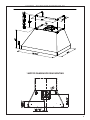 5
5
-
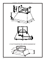 6
6
-
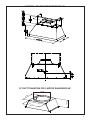 7
7
-
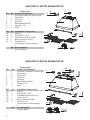 8
8
-
 9
9
-
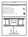 10
10
-
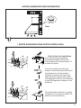 11
11
-
 12
12
-
 13
13
-
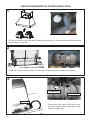 14
14
-
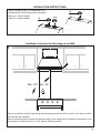 15
15
-
 16
16
-
 17
17
-
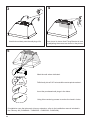 18
18
-
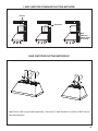 19
19
-
 20
20
-
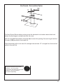 21
21
-
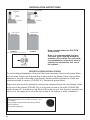 22
22
-
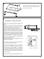 23
23
-
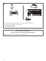 24
24
-
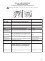 25
25
-
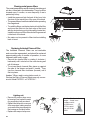 26
26
-
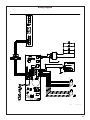 27
27
-
 28
28
-
 29
29
-
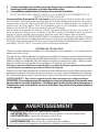 30
30
-
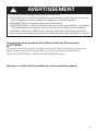 31
31
-
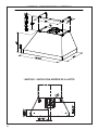 32
32
-
 33
33
-
 34
34
-
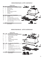 35
35
-
 36
36
-
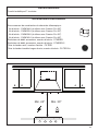 37
37
-
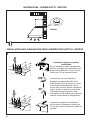 38
38
-
 39
39
-
 40
40
-
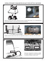 41
41
-
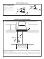 42
42
-
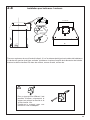 43
43
-
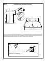 44
44
-
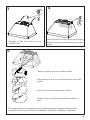 45
45
-
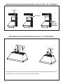 46
46
-
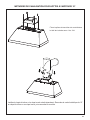 47
47
-
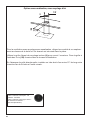 48
48
-
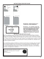 49
49
-
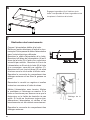 50
50
-
 51
51
-
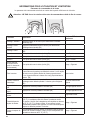 52
52
-
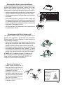 53
53
-
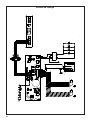 54
54
-
 55
55
-
 56
56
-
 57
57
-
 58
58
-
 59
59
-
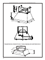 60
60
-
 61
61
-
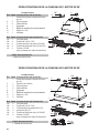 62
62
-
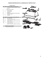 63
63
-
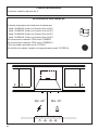 64
64
-
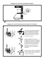 65
65
-
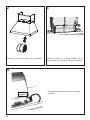 66
66
-
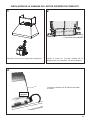 67
67
-
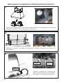 68
68
-
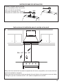 69
69
-
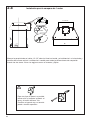 70
70
-
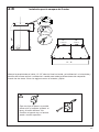 71
71
-
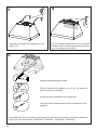 72
72
-
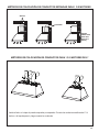 73
73
-
 74
74
-
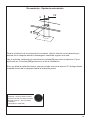 75
75
-
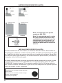 76
76
-
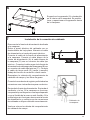 77
77
-
 78
78
-
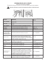 79
79
-
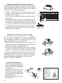 80
80
-
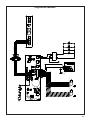 81
81
-
 82
82
-
 83
83
-
 84
84


Faber Camino Pro - 36 SS 1200 cfm Guía de instalación
- Categoría
- Campanas de cocina
- Tipo
- Guía de instalación
- Este manual también es adecuado para
en otros idiomas
Artículos relacionados
-
Faber Camino Pro - 36 SS 1200 cfm Guía de instalación
-
-
-
Faber INLX21SSV Manual de usuario
-
-
-
Liebherr NOPR30SSV Guía de instalación
-
-
-
Otros documentos
-
AGA AMCHD36IVY Manual de usuario
-
-
-
Inalto AIH60W Guía de inicio rápido
-
FIELD CONTROLS EVENAIR KS-4 Manual de usuario
-
Giacomini R279B Instrucciones de operación
-
Saber Compact EZ Outdoor Kitchen I Series Assembly Instructions
-