Wagan SlimLine AC Inverter 2000 Watt Manual de usuario
- Categoría
- Adaptadores de corriente
- Tipo
- Manual de usuario

Item No. / Artículo No : 3724 (12V DC Input)
3724-4 (24V DC Input)
3724-8 (48V DC Input)
User’s Manual / Manual de Usuario
Please visit our website for the latest information on this product.
Visite nuestro sitio web para obtener la información más reciente sobre este producto.
RoHS
compliant
Slimline
™
2000

Slimline
™
Power Inverters by Wagan Tech
®
www.wagan.com
1
INTRODUCTION
Thank you for purchasing a Wagan Tech
®
Slimline
™
Power Inverter. With minimal
care and proper treatment, it will provide years of reliable service.
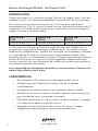
This power inverter converts direct current (DC) to alternating household current
(AC). This inverter operates from a DC power source only. The level of direct
current allowed by this inverter varies by model. Please refer to the chart below:
Item No.
3724
Item No.
3724-4
Item No.
3724-8
12V DC Input 24V DC Input 48V DC Input
In an industry where the actual wattage output varies so greatly, Wagan Tech
is proud to introduce TrueRated Power
™
technology. All our inverters feature
TrueRated Power. That simply means power tested and rated at a period of
24 hours continuous usage under full load. Many competing products claim
“continuous duty”, when they are often only 20 minutes of “continuous” duty at
full output. We also build our inverters with High Peak Surge rating to support
motorized appliance start up.
Read and understand this manual before installing and operating this inverter.
Keep this manual for future use.
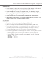
FEATURES
• Two LED indicators display the operating status of the inverter.
• Multiple AC outlets allow for more than one appliance to be powered at
the same time.
• Mounting holes allow for safe stable installation.
• High Peak Power: Allows you to power appliances that require large initial
start-up wattage.
• Low Battery Alarm: The inverter sounds an audible alarm then turns itself
off if the battery voltage becomes too low.
• Auto Shutdown/Reset Protection: The inverter temporarily shuts itself down
to protect itself from overheating.
• Overload/Short Circuit Protection: The inverter automatically turns itself off
if the connected load is too large or if it shorts.

©2018 Wagan Corporation. All Rights Reserved.
Wagan Tech and wagan.com are trademarks used by Wagan Corporation.
User’s Manual—Read before using this equipment
www.wagan.com
2
WARNINGS
• Do not attempt to open the inverter enclosure. High voltage inside the unit
is the same type of power as your electrical outlets at home.
• Do not operate the inverter in or around water. The voltage of the unit
makes it an electrical shock hazard if operated in wet conditions. Do not
let any plugged in appliance’s cord get wet.
• Do not connect the AC inverter directly to another AC power source.
• Keep it away from children: The inverter produces power just like AC wall
outlets at home and it should be treated seriously.
CAUTIONS
• Do not use the inverter in a positively grounded vehicle.
• Allow at least 2 inches of clearance around the inverter for air flow.
• If you operate the inverter in a moving vehicle, you need to secure the
inverter to prevent it from shifting around while the vehicle is moving.
• If there is anything wrong with the inverter, disconnect all power.
• The following operations will damage and void the warranty of the inverter:
∗ Reversing polarity by connecting DC cables to incorrect terminals.
∗ Connecting the inverter to a power source greater than the following:
#3724 — 15V DC
#3724-4 — 30V DC
#3724-8 — 60V DC

Slimline
™
Power Inverters by Wagan Tech
®
www.wagan.com
3
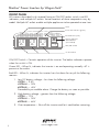
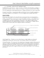
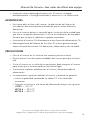
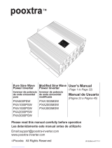
FRONT PANEL
All inverters described in this manual have an ON/OFF rocker switch, two LED
indicators, and multiple AC outlets. Actual locations of these components vary by
model. Multiple AC outlets enable multiple appliances to be operated at one time.
ON/OFF Switch – Controls operation of the inverter. The below indicators operate
when the switch is ON.
Green LED – When lit, indicates the inverter is on and operating normally. AC is
present at the outlets.
Red LED – When lit, indicates the inverter has shut down for any of the following
reasons:
1. Low DC battery voltage – less than the following voltage:
#3724 — 9.5V
#3724-4 — 20V
#3724-8 — 40V
Preceded by an audible alarm. Charge the battery as soon as possible.
2. High battery voltage – greater than the following voltage:
#3724 — 15V
#3724-4 — 30V
#3724-8 — 60V
3. Over temperature − Shut off the inverter and let it cool before restarting.
Fault Indicator (red)
Power On Indicator (green)
3x AC Outlets
Vents
Port for Optional
Wired Remote
(not included)
ON/OFF Switch

©2018 Wagan Corporation. All Rights Reserved.
Wagan Tech and wagan.com are trademarks used by Wagan Corporation.
User’s Manual—Read before using this equipment
www.wagan.com
4
4. Overload – reduce the AC appliance load.
Audible Alarm (not shown) – when it sounds, it indicates that the battery voltage is
getting low and the inverter is about to shut down. If you can reduce the AC load,
you can temporarily extend operating time. Charge the battery as soon as possible.
Remote Control Port – An optional cable and Remote Switch assembly provides a
convenient remote On/Off feature. Visit www.wagan.com to order Item 2323.
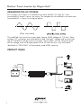
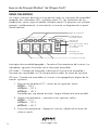
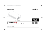
REAR PANEL
All inverters described in this manual have two terminals for connecting battery
cables. One terminal is the Positive (+) terminal [red]; the other is the Negative (−)
terminal [black]. The Positive battery cable should have a Battery Protection Fuse
installed within one foot of the battery connection. The negative cable can be
directly attached to the negative battery terminal. In some cases, a metal vehicle
frame can be used as part of the negative cable to the battery.
Cooling Fans (internal)
Positive Terminal (red)
Negative Terminal (black)
Vent Grills
Ground Terminal
High Speed Fan – The fans turn on when there is a high load or an elevated
temperature to keep the inverter cool. Do not block. Keep 2-inch clearance.
Ground Terminal – This terminal is for attaching a 6 gauge insulated safety ground
wire. This safety wire protects personnel if there is an unlikely failure in either the
cabling or enclosure insulation. Do not directly connect this ground to the negative
DC terminal on the inverter. This safety wire is to be connected to the vehicle
frame or earth ground or negative battery terminal as described in the installation
procedure.

Slimline
™
Power Inverters by Wagan Tech
®
www.wagan.com
5
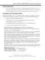
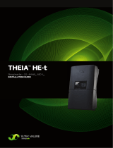
MEASURING THE AC VOLTAGE
This inverter’s AC output is a modified sine wave (MSW) 115 volts AC. Your
household AC output is pure sine wave. The comparison of modified sine wave and
household AC is shown in the figure below.
(Pure sine wave)
This modified sine wave has a root mean square (RMS) voltage of 115 volts. Most
ordinary AC voltmeters are calibrated to read “average” voltage and assume that
the AC waveform will be a pure sine wave. These meters will not correctly read
MSW voltage, and will display about 20 to 30 volts too low. Any multi-meter
identified as “TRUE RMS” will accurately read MSW correctly.
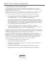
PRODUCT USAGE
FU
SE

©2018 Wagan Corporation. All Rights Reserved.
Wagan Tech and wagan.com are trademarks used by Wagan Corporation.
User’s Manual—Read before using this equipment
www.wagan.com
6
BASIC OPERATION
• Turn ON the power switch that is located at the front of the inverter, and
the green LED indicator will light up as an indicator that the unit is working.
• Plug your appliance(s) into the AC socket(s) at the front of the inverter.
PLANNING THE INVERTER SYSTEM
Any large wattage inverter system requires planning before installation. There are
several steps to the planning process so the user must determine the following:
• Maximum inverter wattage required.
• Operating time (run time) needed between battery recharges.
• Battery bank capacity in amp-hours.
• Charger requirement to charge batteries within a practical time.
• Distance between battery bank and inverter.
DETERMINING MAXIMUM APPLIANCE WATTAGE
Maximum AC Appliance Wattage is the first factor in planning battery and
charging systems. Some background:
Large microwave oven specifications list cooking power (watts) and appliance
power. Appliance power is the AC load the inverter has to supply.
Most other electrical tools, appliances and audio/video equipment have labels
that list the unit's power requirements in watts. If the tool or device is rated in
amps, multiply the amps by 115 (115V AC) to determine the watts. For example,
a power tool rated at 4-amps will draw 460 watts.
Determine the wattage of each appliance you need to simultaneously operate.
Add all of the appliance wattages to obtain an estimated “total watts” number.
Remember to consider the start-up surge that motorized appliances will cause.
Do not exceed the surge rating of this inverter. This can cause immediate
overload shut down.
At maximum continuous output, this inverter requires a DC power supply (battery
bank) that can continuously supply required amps at the following level for the
duration of the run time.
#3724 (12V DC Input) — 200 amps @ 12V
#3724-4 (24V DC Input) — 100 amps @ 24V
#3724-8 (48V DC Input) — 50 amps @ 48V

Slimline
™
Power Inverters by Wagan Tech
®
www.wagan.com
7
CONFIGURING THE BATTERY BANK
To determine the minimum battery ampere-hour rating that you will need to
operate appliances from the inverter, and any DC appliances powered by the
battery bank, follow these steps:
(The following calculations are specific to 12V systems. For 24V or 48V systems,
a different calculation is required but the same principles should apply.)
1. List the maximum continuous wattage that the inverter has to supply.
2. Estimate the number of hours the appliances will be in use between
battery recharges. This will vary depending on appliances.
For example, a typical home-use coffee maker draws 500 watts during its
brew time of 5 minutes, but it only requires 100 watts thereafter to maintain
the temperature of the pot. Similarly, a typical use of a microwave oven is
only for a few minutes. Some longer operating time appliances are lamps,
TV’s, computers, and refrigerator/freezers.
3. Determine the total watt-hours of energy needed. This is done by
multiplying average power consumption in watts by hours of run time. For
example: 1,000 watts for 10 hours = 10,000 watt hours.
To get an estimate of the maximum current (in amps) that a battery bank must be
capable of delivering to the inverter, divide the load watts by 10. For example a
1,000 watt appliance load will need 100 amps at 12 Volts DC.
Using the 1,000 watts for 10 hours example as above, then 100 amps is
needed for 10 hours. This provides us with the basic amp-hours (Ah) of battery
that is required. Ten hours at 100 amps equals 1,000 Amp Hours (Ah). This
answer is just a beginning of configuring the battery bank because there are
additional factors that determine actual run time. These include:
• AC appliance load and time in use (basic Ah)
• Cable gauge and length (cable losses)
• Charge level of the batteries (between use, chargers have to be able to
fully charge the batteries)
• Temperature of the batteries (colder batteries provide fewer amps)
• Age and condition of the batteries (older batteries lose Ah capacity)

©2018 Wagan Corporation. All Rights Reserved.
Wagan Tech and wagan.com are trademarks used by Wagan Corporation.
User’s Manual—Read before using this equipment
www.wagan.com
8
• Compliance with turning off unnecessary AC loads
• Use of DC appliances and compliance with turning off unnecessary DC
loads
• If the inverter is installed in a vehicle and the alternator output in Amps
cannot supply enough current for the inverter, additional batteries are
required to supply the required current.
DERATING THE BATTERY BANK
Most lead-acid batteries have a rating expressed in amp-hours (Ah). The most
common rating of Ah is at the “20-hour rate”.
For example, if a 20Ah battery is discharged at a 1 amp rate, it will take 20
hours to discharge that battery. The terms “charged” and “discharged” relate to
actual battery voltage. This means that the output voltage of a nominal 12 volt
battery starts at 13.2 volts (fully charged) then drops to 10.6 volts (discharged).
If the load on the battery causes the battery to discharge faster than the 20 hour
rate, the capacity (Ah) of the battery is measurably reduced (derated). Derating
is a major run time factor. Some benchmarks are as follows:
• If an 100 Ah Battery is discharged at 100 Amps, the battery capacity acts
like a 56 Ah battery.
• If an 100 Ah Battery is discharged at 200 Amps, the battery capacity acts
like a 32 Ah battery.
Again, both high discharge rates are faster than the 20-hour rate so battery
capacity seems lower.
INSTALLATION
Safe installation requires that a Battery Protection fuse is installed within one foot of
the positive (+) battery Terminal [red]. Use ANL marine fuses or equal because they
do not spark when they blow. Use an appropriate fuse holder for the fuse. ANL
fuse holders can be mounted so they do not move in a vehicle or vessel.

Slimline
™
Power Inverters by Wagan Tech
®
www.wagan.com
9
CONNECTING THE INVERTER
Loose DC (battery) connections will result in a severe voltage drop that can
cause damage to connectors, conductors, and insulation and can cause
sparking. Reverse polarity connection can permanently damage the inverter.
Damage caused by reverse polarity will void the warranty.
WARNING:
Venting batteries produce explosive, corrosive gases. There is danger of
explosion. DO NOT connect or disconnect BATTERY cables directly after battery
discharge or recharge. Make sure that the battery bank area is well vented
before attaching or removing cables.
NOTES: All recommended cable gauges and fuse sizes are located at the rear
of this manual in the Cable Gauge Table. The table describes Cable Gauges for
lengths greater than supplied cables.
“Round Trip” refers to actual cable distance in feet from the POS (+) battery
terminal to the inverter and back to the NEG (−) battery terminal.
Crimp-on ring terminals are required on all cable ends. The cable ends need to
be stripped of insulation for ½ inch before crimping on ring terminals. Select
a crimp terminal size to fit the cable gauge and inverter and battery terminal
connectors. After crimping, make sure that the cable connectors are secure on
the cables so there are no loose connections.
CAUTION: Making an initial connection between the positive cable end and
the inverter’s positive terminal may cause a spark. This is normal and is a result
of capacitors in the inverter starting to charge. Because of the possibility of
sparking, it is extremely important that both the inverter and the battery bank be
positioned away from any source of flammable fumes or gases. Failure to heed
this warning can result in fire or explosion. Do not make the positive terminal
connection immediately after the batteries have been charging. Allow time for
the battery gasses to vent to outside air.
GROUND TERMINAL WIRE REQUIREMENTS
Use a minimum of 6 gauge stranded wire for enclosure ground wire. Connect
this to the chassis of your vehicle or to the grounding system in your boat. In
a city, the ground wire can connect to a metal cold water pipe that goes
underground. In remote locations, the ground wire can be connected to an
“earth ground”. This can be an attachment to a 6 foot long copper clad metal
rod driven into the ground. In the unlikely event of a short circuit, operating the
inverter without proper grounding can result in electrical shock. Do not directly
connect this ground to the negative terminal on the inverter.

©2018 Wagan Corporation. All Rights Reserved.
Wagan Tech and wagan.com are trademarks used by Wagan Corporation.
User’s Manual—Read before using this equipment
www.wagan.com
10
INSTALLATION PROCEDURE
1. Mount the inverter in a secure location. If the inverter is to be mounted
on a wall, mount it horizontally. Make sure that the front and rear of the
inverter has free air flow.
2. Make sure the cables are the proper gauge and have the fuse holder as
close to the battery bank’s Positive (+) terminal as possible.
3. Install the fuse in the Positive (+) cable (Refer to the Cable Gauge Table at
rear of manual).
4. Make sure the ON/OFF switch located on the front panel of the inverter is
in the OFF (O) position.
5. Install the ground wire from the ground terminal to the grounding point.
6. Connect the Negative (−) cable end to the inverter terminal and battery's
Negative Terminal. Make sure you have good, secure connections.
7. Recheck and make sure the DC cable fuse is installed in the fuse holder.
8. Attach the positive cable to the Positive (+) DC connector on the battery
and then the inverter. Make sure the connections are tight and secure.
9. Turn on the inverter from the Front Panel ON/OFF Switch.
10. Make certain that the green Operating LED is lit and the red FAULT LED
indicator is not lit.
11. Turn OFF (O) the inverter. The Fault LED may briefly flash; this is normal.
The audible alarm may also sound a short chirp; this is also normal.
12. When you have confirmed that the appliance to be operated is turned off,
plug the appliance into one of the AC outlets on the inverter.
13. Turn the inverter on.
14. Turn the appliance on. The appliance should begin working.
15. Observe the LED indicators for normal operation.
If flooded lead acid batteries are used, be sure that periodic checks of battery
electrolyte levels are accomplished. Follow battery manufacturer’s instructions in
keeping the electrolytes at the proper level. Be sure to use pure distilled water
when replacing evaporated electrolyte liquid.

Slimline
™
Power Inverters by Wagan Tech
®
www.wagan.com
11
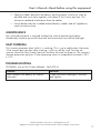
RECOMMENDATIONS
• If the power inverter makes a beeping sound, turn OFF the inverter,
disconnect all appliances from the inverter. The beeping sound is the low
battery warning that indicates that the voltage of the battery power supply
is getting low. Please restart the vehicle engine to charge the battery
before using it to operate the inverter again.
• When you are not using the inverter, turn the power switch to OFF. This
conserves battery power.
OPERATING TIPS
ADDING AN EXTENSION CORD
You may use up to 100 feet of high quality, heavy-duty extension cord. A longer
cord will result in reduced power to appliances.
BUZZ IN AUDIO SYSTEMS
Some stereo systems and portable radios will emit a buzzing noise from their
speakers when operated from the power inverter because the power supply in
the device does not adequately filter the modified sine wave produced by the
power inverter. The only solution is to use a sound system that incorporates a
higher quality power supply.
TELEVISION INTERFERENCE
Operating the power inverter can interfere with television reception on some
channels. If this situation occurs, the following steps may help to alleviate the
problem:
• Do not operate high power loads with the power inverter while watching
television.
• Make sure the antenna feeding your television provides an adequate static-
free signal and you are using good quality cable between the antenna and
the television.
• Move the television as far away from the power inverter as possible.

©2018 Wagan Corporation. All Rights Reserved.
Wagan Tech and wagan.com are trademarks used by Wagan Corporation.
User’s Manual—Read before using this equipment
www.wagan.com
12
• Keep the cables between the battery and the power inverter as short as
possible and twist them together with about 2 to 3 twists per foot. This
minimizes radiated interference from the cables.
• Ferrite beads may be installed around battery cables and AC appliance
cords to reduce noise.
MAINTENANCE
Very little maintenance is required to keep the inverter operating properly.
Periodically check to ensure all terminals and connectors are secure and tight.
HEAT DISPERSAL
The inverter generates heat while it is working. This is not a malfunction. However,
if the inverter gets too hot while working, it will turn off by itself. Position the
inverter where air flows freely around it to allow the heat to disperse. The inverter’s
thermal protection prevents it from operating when its temperature exceeds 130ºF
± 10 º F.
TROUBLESHOOTING
PROBLEM: Low or No Output Voltage – Fault LED Lit
Reason Solution
Poor contact with battery or inverter
terminals.
Clean terminals thoroughly. Reinstall
and tighten.

Slimline
™
Power Inverters by Wagan Tech
®
www.wagan.com
13
PROBLEM: Inverter Automatically Shut Down – Fault LED Lit
Reason Solution
Battery voltage below
#3724 — 9.5V
#3724-4 — 20V
#3724-8 — 40V
Charge or replace battery.
Inverter is too hot.
(Thermal protection mode.)
Allow inverter to cool.
Check for adequate ventilation.
Reduce the load on the inverter to
rated continuous power output.
Unit may be defective. See warranty and call customer service.
Equipment being operated draws too
much power.
Use a higher capacity inverter or do
not use this equipment.
PROBLEM: Continuous Buzzing Sound
Reason Solution
Input voltage below
#3724 — 10.5V
#3724-4 — 21.0V
#3724-8 — 42.0V
Keep input voltage above:
#3724 — 10.5V
#3724-4 — 21.0V
#3724-8 — 42.0V
Poor or weak battery condition. Recharge or replace battery.
Poor or loose cable connection. Inspect terminals and tighten all
connections.
Inadequate power being delivered to
the inverter or excessive voltage drop.
Use heavier gauge DC cable.
Keep cable length as short as possible.
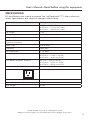
DISPOSAL/RECYCLING OF INVERTER
Electronic products are known to contain materials that are toxic if improperly
disposed. Contact local authorities for disposal and recycling information.

©2018 Wagan Corporation. All Rights Reserved.
Wagan Tech and wagan.com are trademarks used by Wagan Corporation.
User’s Manual—Read before using this equipment
www.wagan.com
14
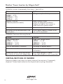
SPECIFICATIONS
All specifications are typical at nominal line, half load and 77ºF unless otherwise
noted. Specifications are subject to change without notice.
Name Description
Input #3724 — 11-15V DC Input
#3724-4 — 21-30V DC Input
#3724-8 — 42-60V DC Input
AC Output 115 V
Output frequency 60 Hz
Output waveform Modified Sine Waveform
TrueRated
™
Power
(24-hour continuous)
2,000 Watts
Peak Surge 4,500 Watts
Efficiency Max. 90%
No load current < 1.0 Amps
Low battery alarm #3724 — 10.5V ± 0.5V DC
#3724-4 — 21.0V ± 1.0V DC
#3724-8 — 42.0V ± 2.0V DC
Low battery automatic shutdown #3724 — 9.5V ± 0.5V DC
#3724-4 — 20.0V ± 1.0V DC
#3724-8 — 40.0V ± 2.0V DC
Alarm and thermal shutdown 130 ºF ± 10º
AC Outlets
3 NEMA 5-15 USA
Dimensions (L x W x H) inches
14.5 × 5.3 × 2.5 (in.)
Net Weight
4.8 lbs.

Slimline
™
Power Inverters by Wagan Tech
®
www.wagan.com
15
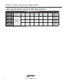
CABLE GAUGES BASED ON ROUND TRIP CABLE LENGTHS
2,000W (Item No. 3724)
Input
Cable
length (feet)
8 9–10 11–14 15–17 18–21 22 23–25
Fuse*
(Amps)
12V
(#3724)
Gauge
(AWG)
2 2 0 0 00 000 000 250
24V
(#3724-4)
6 4 2 2 0 0 0 120
48V
(#3724-8)
6 6 4 4 2 2 2 60
*Battery protection fuse not included.

www.wagan.com
WAGAN Corp. Limited Warranty
The WAGAN Corporation warranty is limited to products sold only in
the United States.
Warranty Duration:
Product is warranted to the original purchaser for a period of two (2) years from the
original purchase date, to be free of defects in material and workmanship. WAGAN
Corporation disclaims any liability for consequential damages. In no event will
WAGAN Corporation be responsible for any amount of damages beyond the amount
paid for the product at retail.
Warranty Performance:
During the warranty period, a product with a defect will be replaced with a
comparable model when the product is returned to WAGAN Corporation with an
original store receipt. WAGAN Corporation will, at its discretion, replace or repair
the defective part. The replacement product will be warranted for the balance of the
original warranty period. This warranty does not extend to any units which have been
used in violation of written instructions furnished.
Warranty Disclaimers:
This warranty is in lieu of all warranties expressed or implied and no representative
or person is authorized to assume any other liability in connection with the sale of our
products. There shall be no claims for defects or failure of performance or product
failure under any theory of tort, contract or commercial law including,but not limited
to negligence, gross negligence, strict liability, breach of warranty, and breach of
contract.
Returns:
WAGAN Corporation is not responsible for any item(s) returned without an official
Return Authorization number (RA#). Please contact our customer service team by
phone or email to obtain an RA#. You can also visit our website and chat with our
team during our normal business hours. For more details and instructions on how to
process a warranty claim, please read the “Returns” section under the “Contact” page
on our website. WAGAN Corporation is not responsible for any shipping charges
incurred in returning the item(s) back to the company for repair or replacement.
Register your product online at http://tinyurl.com/wagan-registration to be added to
our email list. You will receive previews on our upcoming products, promotions, and
events.
©2015

Inversor de Energía Slimline
™
de Wagan Tech
®
17
www.wagan.com
INTRODUCCIÓN
Gracias por adquirir un inversor de energía Slimline
™
de Wagan Tech
®
. Con unos
cuidados mínimos y un tratamiento adecuado le ofrecerá años de servicio fiable.
Este inversor convierte la corriente continua (CC) en corriente alterna para
electrodomésticos (CA). El inversor funciona con una fuente de alimentación de CC
únicamente. El nivel de corriente continua que ofrece este inversor varía según el
modelo. Consulte el siguiente cuadro:
Artículo N
O
3724
Artículo N
O
3724-4
Artículo N
O
3724-8
Voltaje de entrada 12 V CC Voltaje de entrada 24 V CC Voltaje de entrada 48 V CC
En una industria en la que varía tanto la salida de vatios real, Wagan Tech se
enorgullece en presentar la tecnología TrueRated Power
™
. Los cuatro inversores
disponen de TrueRated Power. Significa que la energía se ha probado y calculado
en un periodo de 24 horas de uso continuo a carga completa. Muchos otros
productos afirman un “funcionamiento continuo”, mientras que a menudo solamente
ofrecen 20 minutos de uso “continuo” a plena capacidad. También fabricamos
nuestros inversores con una clasificación de subida en punta alta para soportar el
encendido de aparatos motorizados.
Lea y comprenda este manual antes de instalar y usar este inversor. Conserve este
manual como referencia en el futuro.
CARACTERÍSTICAS
• Dos indicadores LED muestran el estado operativo del inversor.
• Múltiples tomas de CA permiten alimentar más de un aparato
simultáneamente.
• Los agujeros de montaje permiten una instalación segura y estable.
• Alta potencia en punta: Le permite alimentar aparatos que requieran una
gran cantidad de vatios inicial para el arranque.
• Alarma de batería baja: El inversor emite una alarma audible y se apaga
si la voltaje de la batería se gasta en exceso.
• Apagado automático/Protección de reinicio: El inversor se apaga
temporalmente para protegerse contra sobrecalentamiento.
Item No. / Artículo No/ Article no : 2544Item No. / Artículo No/
Article no : 2544

Manual de Usuario—Leer antes de utilizar este equipo
© Corporación Wagan 2018. Todos los derechos reservados.
Wagan Tech y wagan.com son marcas registradas de la Corporación Wagan.
18
www.wagan.com
• Protección contra sobrecarga/cortocircuito: El inversor se apaga
automáticamente si la carga conectada es excesiva o si se cortocircuita.
ADVERTENCIAS
• No intente abrir el chasis del inversor. La alta tensión del interior de
la unidad es del mismo tipo de alimentación que las tomas eléctricas
domésticas.
• No use el inversor dentro ni cerca del agua. La tensión de la unidad hace
que sea un riesgo de electrocución si se usa en condiciones de humedad.
No deje que se moje el cable de un aparato conectado.
• No conecte el inversor CA directamente a otra fuente de alimentación CA.
• Manténgalo fuera del alcance de los niños: El inversor genera energía
como una toma de corriente CA doméstica y debe tratarse con seriedad.
PRECAUCIONES
• No use el inversor en un vehículo con conexión positiva a tierra.
• Deje al menos 5 cm de espacio alrededor del inversor para que circule el
aire.
• Si usa el inversor en un vehículo en movimiento, debe asegurar el inversor
para evitar que se mueva cuando el vehículo lo haga.
• Si encuentra cualquier problema con el inversor, desconecte toda la
alimentación.
• Las operaciones siguientes dañarán el inversor y anularán la garantía:
∗ Invertir la polaridad conectando los cables CC a los terminales
incorrectos.
∗ Conectar el inversor a una fuente de alimentación mayor a lo siguiente:
#3724 — 15V CC
#3724-4 — 30V CC
#3724-8 — 60V CC

Inversor de Energía Slimline
™
de Wagan Tech
®
19
www.wagan.com
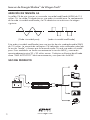
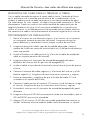
PANEL DELANTERO
Los cuatro inversores descritos en este manual tienen un interruptor de encendido/
apagado, dos indicadores LED, y múltiples tomas CA. Las ubicaciones de los
componentes varían según el modelo. Múltiples tomas CA permiten usar múltiples
aparatos simultáneamente. A continuación se muestra un diagrama de un panel
frontal habitual.
Interruptor de encendido/apagado – Controla el funcionamiento del inversor. Los
indicadores siguientes funcionan con el interruptor encendido.
LED verde – Cuando está iluminado, indica que el inversor está encendido y
funciona con normalidad. La CA está presente en todas las tomas de corriente.
LED rojo - Cuando está encendido, el inversor se ha apagado por alguno de los
motivos siguientes:
1. Baja tensión de batería CC – menos de los siguientes voltios:
#3724 — 9.5 V
#3724-4 — 20 V
#3724-8 — 40 V
Precedido por una alarma acústica. Cargue la batería lo antes posible.
2. Alta tensión de batería – superiores a las siguientes voltios:
#3724 — 15 V
#3724-4 — 30 V
#3724-8 — 60 V
3. Exceso de temperatura – Apague el inversor y déjelo enfriar antes de
volver a usarlo.
Indicador de
avería (rojo)
Luz indicadora de
encendido (verde)
3x Conexiones de CA
Interruptor de
encendido/apagado
Rejilla de ventilación
Puerto para control remoto
con cable opcional
(no incluido)

Manual de Usuario—Leer antes de utilizar este equipo
© Corporación Wagan 2018. Todos los derechos reservados.
Wagan Tech y wagan.com son marcas registradas de la Corporación Wagan.
20
www.wagan.com
4. Sobrecarga – Reduzca la carga de aparatos CA.
Alarma acústica (no mostrada) – al sonar, indica que la tensión de batería está
bajando y el inversor está a punto de apagarse. Si puede reducir la carga CA
podrá aumentar temporalmente el tiempo de funcionamiento. Cargue la batería lo
antes posible.
Puerto de control remoto – La opción de un cable y un interruptor de activación a
distancia ofrecen una práctica función de encendido/apagado remoto. Visita
www.wagan.com a la orden de artículo 2323.
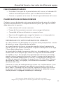
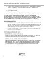
PANEL TRASERO
Los inversores descritos en este manual tienen dos terminales para conectar cables
de batería. Un terminal es el terminal positivo (+) [rojo] y el otro es el terminal
negativo (-) [negro]. El cable de batería positivo debería tener un fusible de
protección de batería instalado a menos de un pie (30 cm) de la conexión de la
batería. El cable negativo puede conectarse directamente al terminal negativo de
la batería. En algunos casos se puede usar el chasis metálico de un vehículo como
parte del cable negativo a la batería.
Ventiladores (internos)
Terminal positivo (rojo)
Terminal negativo (negro)
Rejillas de ventilación
Terminal a tierra
Ventilador de alta velocidad – El ventilador se enciende cuando hay una carga
significativa o elevada temperatura para mantener frío el inversor. No lo obstruya.
Mantenga 5 cm de espacio.
Terminal a tierra – A este terminal se puede conectar un cable aislado a tierra
calibre 6 de seguridad. Este cable de seguridad es de protección personal en caso
de un fallo poco común en el cableado o en el aislamiento. No conecte este cable
directamente a ningún terminal de CC en el inversor. Este cable de seguridad se
debe conectar al bastidor del vehículo o a tierra, o al terminal negativo de la
batería como se describe en el procedimiento de instalación.

Inversor de Energía Slimline
™
de Wagan Tech
®
21
www.wagan.com
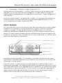
MEDICIÓN DE TENSIÓN CA
La salida CA de este inversor es una onda sinusoidal modificada (MSW) de 115
voltios CA. La salida CA doméstica es una onda sinusoidal pura. La comparación
de la onda sinusoidal modificada y la CA doméstica se muestra en la imagen
siguiente.
(Pure sine wave)
(Onda sinusoidal pura) (onda sinusoidal modificada)
Esta onda sinusoidal modificada tiene una tensión de raíz cuadrada media (RMS)
de 115 voltios. La mayoría de voltímetros CA habituales están calibrados para leer
la tensión “media” y asumen que la forma de onda CA será una onda sinusoidal
pura. Estos medidores no leerán correctamente la tensión MSW, y mostrarán
aproximadamente entre 20 y 30 voltios menos. Cualquier multímetro identificado
como “RMS AUTÉNTICO” leerá correctamente y con precisión la MSW.
USO DEL PRODUCTO
FU
SE

Manual de Usuario—Leer antes de utilizar este equipo
© Corporación Wagan 2018. Todos los derechos reservados.
Wagan Tech y wagan.com son marcas registradas de la Corporación Wagan.
22
www.wagan.com
FUNCIONAMIENTO BÁSICO
• Encienda el interruptor de la parte delantera del inversor, el indicador LED
verde se encenderá para mostrar que la unidad está funcionando.
• Conecte sus aparatos a las tomas de CA de la parte delantera del inversor.
PLANIFICACIÓN DEL SISTEMA INVERSOR
Cualquier inversor de elevados vatios precisa de planificación antes de instalarlo.
El proceso de planificación se compone de diversos pasos, por lo que el usuario
debe determinar lo siguiente:
• Vatios máximos del inversor necesarios.
• Tiempo de funcionamiento necesario entre recargas de baterías.
• Capacidad del banco de baterías en amperios-horas.
• Requisitos del cargador para cargar las baterías en un tiempo práctico.
• Distancia entre el banco de baterías y el inversor.
DETERMINAR LOS VATIOS MÁXIMOS DEL APARATO
Los vatios máximos CA del aparato son el primer factor para planificar sistemas
de baterías y carga. Información de trasfondo:
Las especificaciones de hornos microondas grandes indican la potencia de
cocción (vatios) y la potencia del aparato. La potencia del aparato es la carga
CA que debe proporcionar el inversor.
La mayoría de las demás herramientas eléctricas, electrodomésticos y equipos
audiovisuales tienen etiquetas que indican los requisitos de alimentación de
la unidad en vatios. Por ejemplo, las especificaciones de hornos microondas
grandes indican la potencia de cocción (vatios) y la potencia del aparato (la
carga CA que debe proporcionar el inversor). Si la herramienta o dispositivo
se indica en amperios, multiplique los amperios por 115 (115 voltios CA) para
determinar los vatios. Por ejemplo, una herramienta indicada en 4 amperios
absorberá 460 vatios.
Determine los vatios de cada aparato que quiera usar simultáneamente. Sume
los vatios de todos los aparatos para obtener una estimación numérica de
"vatios totales". Recuerde tener en cuenta la subida de arranque que causarán
los aparatos motorizados. No exceda la clasificación de subida del inversor.
Podría provocar un apagado inmediato por sobrecarga.

Inversor de Energía Slimline
™
de Wagan Tech
®
23
www.wagan.com
Con la potencia continua máxima, este inversor requiere una fuente de
alimentación de CC (banco de baterías) que pueda suministrar continuamente
los amperios necesarios según el siguiente nivel de tiempo de operación.
#3724 (entrada de 12V CC) — 200 amperios @ 12 V
#3724-4 (entrada de 24V CC) — 100 amperios @ 24 V
#3724-8 (entrada de 48V CC) — 50 amperios @ 48 V
CONFIGURAR EL BANCO DE BATERÍAS
Para determinar la clasificación de amperios-horas mínima de la batería
necesaria para usar aparatos con el inversor, y cualquier aparato CC
alimentado por el banco de baterías, siga estos pasos:
(Los siguientes cálculos corresponden específicamente a sistemas de 12 V. Para
sistemas de 24 V o 48 V, se requieren otros cálculos pero se deben aplicar los
mismos principios.)
1. Liste los vatios continuos máximos que debe alimentar el inversor.
2. Calcule el número de horas que se usarán los aparatos entre recargas de
baterías. Variará según los aparatos.
3. Por ejemplo, una cafetera doméstica habitual absorbe 500 vatios
durante el tiempo de preparación de 5 minutos, pero solamente
necesita 100 vatios después para mantener la temperatura de la jarra.
Igualmente, el uso normal de un horno microondas es de solamente unos
minutos. Algunos aparatos que funcionan más tiempo son lámparas, TV,
ordenadores y frigoríficos/congeladores.
4. Determine los vatios-horas de energía necesarios en total. Hágalo
multiplicando el consumo medio de energía en vatios por las horas de
funcionamiento. Por ejemplo: 1.000 vatios durante 10 horas = 10.000
vatios horas.
Para obtener una estimación de la corriente máxima (en amperios) que un
banco de baterías debe poder entregar al inversor, divida los vatios de carga
por 10. Por ejemplo, un aparato de 1000 vatios necesitará 100 amperios a 12
voltios CC.
Usando los 1000 vatios durante 10 horas como en el ejemplo anterior, se
necesitan 100 amperios durante 10 horas. Esto nos proporciona los amperios-
horas (AH) básicos de batería necesarios. Diez horas a 100 amperios equivalen
a 1.000 amperios-horas (AH). Esta respuesta es solamente el comienzo de
la configuración del banco de baterías, porque hay factores adicionales que

Manual de Usuario—Leer antes de utilizar este equipo
© Corporación Wagan 2018. Todos los derechos reservados.
Wagan Tech y wagan.com son marcas registradas de la Corporación Wagan.
24
www.wagan.com
determinan el tiempo de funcionamiento real. Incluyen:
• Carga de aparatos CA y tiempo de uso (AH básicos).
• Medida y longitud de cable (pérdidas de cable)
• Nivel de carga de las baterías (entre usos, los cargadores deben poder
cargar por completo las baterías)
• Temperatura de las baterías (las baterías más frías proporcionan menos
amperios)
• Edad y estado de las baterías (las baterías más viejas pierden capacidad
de AH)
• Apagar las cargas CA innecesarias.
• Uso de aparatos CC y apagado de cargas CC innecesarias.
• Si el inversor está instalado en un vehículo y la salida del alternador en
amperios no puede proporcionar la corriente suficiente para el inversor,
son necesarias baterías adicionales para proporcionar la corriente.
REDUCIR EL BANCO DE BATERÍAS
La mayoría de baterías de plomo-ácido tienen una clasificación expresada en
amperios-horas (AH). La clasificación más habitual de AH es “a ritmo de 20
horas".
Por ejemplo, si una batería 20AH se descarga a un ritmo de 1 amperio, tardará
20 horas en descargarse. Los términos “cargado” y “descargado” se refieren
a la tensión real de la batería. Esto implica que la tensión de salida de una
batería con 12 voltios nominales comienza a 13.2 voltios (totalmente cargada)
y cae hasta 10.6 voltios (descargada). Si la carga de la batería hace que se
descargue con mayor rapidez que el ritmo de 20 horas, la capacidad (AH) de
la batería se reduce de forma detectable (reducida). La reducción es un factor
importante del tiempo de funcionamiento. A continuación se muestran algunas
referencias:
• Si se descarga una batería de 100 Ah a 100 amperios, la capacidad de
la batería funciona como una batería de 56 Ah.
• Si se descarga una batería de 100 Ah a 200 amperios, la capacidad de
la batería funciona como una batería de 32 Ah.
De nuevo, ambos ritmos de descarga, altos, son más rápidos que el ritmo de 20
horas por lo que la capacidad parece menor.

Inversor de Energía Slimline
™
de Wagan Tech
®
25
www.wagan.com
INSTALACIÓN
Una instalación segura, precisa de la instalación de un fusible de protección de
batería a menos de un pie (30 cm) del terminal positivo (+) de la batería [rojo].
Use fusibles marinos ANL o equivalentes, que no emiten chispa al saltar. Use un
soporte de fusible adecuado para el fusible. Los soportes de fusibles ANL pueden
montarse de forma que no se muevan en un vehículo o embarcación.
CONECTAR EL INVERSOR
Las conexiones sueltas CC (batería) provocarán una grave caída de tensión que
puede dañar los conectores, conductores y el aislamiento, y provocar chispas.
La conexión con polaridad inversa puede dañar permanentemente el inversor.
Los daños causados por una polaridad inversa anularán la garantía.
ATENCIÓN:
Las baterías producen gases explosivos y corrosivos. Riesgo de explosión. NO
conecte ni desconecte los cables de la BATERÍA directamente tras descargar o
recargar la batería. Asegúrese de que la zona del banco de baterías esté bien
ventilada antes de conectar o sacar cables.
NOTAS: Todas las medidas de cable y tamaños de fusible recomendados se
encuentran al final de este manual, en la tabla de medidas de cable. La tabla
describe la medida del cable para longitudes superiores a las de los cables
proporcionados.
“Recorrido” se refiere a la distancia real del cable en pies desde el terminal de
batería POS (+) por el inversor y de vuelta al terminal de batería NEG (-).
Son necesarios terminales en anilla crimpables en todos los extremos de
cable. Los extremos de cable deben pelarse de aislamiento 1,75 cm antes de
crimparlos a los terminales de anilla. Seleccione un tamaño de terminal de
crimpado que se adapte a la medida del cable y a los conectores del inversor y
el terminal de batería. Después de crimpar, asegúrese de que los conectores de
cable estén fijados sobre los cables de forma que no queden conexiones sueltas.
PRECAUCIÓN: Realizar una conexión inicial entre el extremo del cable positivo
y el terminal positivo del inversor puede provocar una chispa. Es normal y se
produce por el inicio de carga de los capacitadores del inversor. Debido a la
posibilidad de chispas, es muy importante que tanto el inversor como el banco
de baterías estén alejados de cualquier fuente de vapores o gases inflamables.
No obedecer esta advertencia puede provocar un incendio o explosión. No
realice la conexión del terminal positivo inmediatamente después de cargar las
baterías. Deje tiempo para que los gases de las baterías se ventilen al aire libre.

Manual de Usuario—Leer antes de utilizar este equipo
© Corporación Wagan 2018. Todos los derechos reservados.
Wagan Tech y wagan.com son marcas registradas de la Corporación Wagan.
26
www.wagan.com
REQUISITOS DEL CABLE PARA EL TERMINAL A TIERRA
Use un cable trenzado de espesor 6 como cable a tierra. Conéctelo al chasis
de su vehículo o a al sistema de puesta a tierra de su embarcación. En la
ciudad, el cable a tierra no debe conectarse a una tubería metálica de agua
fría subterránea. En sitios remotos, el cable a tierra puede conectarse a “tierra”
directamente. Puede ser unido a una varilla metálica de cobre de 6 pies de
longitud clavada en la tierra. En el caso poco probable de un cortocircuito,
utilizar el inversor sin la debida puesta a tierra puede causar choque eléctrico.
No conecte este cable a tierra directamente al terminal negativo en el inversor.
PROCEDIMIENTO DE INSTALACIÓN
1. Monte el inversor en una ubicación segura. Si el inversor se va a montar
en una pared, móntelo en posición horizontal. Asegúrese de que las
partes delantera y trasera del inversor tengan un paso de aire libre.
2. Asegúrese de que los cables sean de la medida adecuada y tener el
soporte de fusible tan cerca del terminal positivo (+) del banco de baterías
como sea posible.
3. Instale el fusible en el cable positivo (+) (Consulte la tabla de medida de
cable en la parte posterior del manual).
4. Asegúrese de que el interruptor de encendido/apagado del panel
delantero del inversor esté en posición de apagado (O).
5. Instale el cable a tierra desde el terminal a tierra hasta el punto de puesta
a tierra.
6. Conecte el extremo del cable negativo (-) al terminal del inversor y al de
batería negativo (-). Asegúrese de tener conexiones correctas y seguras.
7. Vuelva a comprobar y asegúrese de que el fusible del cable CC esté
instalado en el soporte del fusible.
8. Conecte el cable positivo al conector CC positivo (+) de la batería y luego
al inversor. Asegúrese de que las conexiones estén firmes y seguras.
9. Encienda el inversor con el interruptor de encendido/apagado del panel
delantero.
10. Asegúrese de que el LED de funcionamiento verde esté encendido y que el
LED de ERROR rojo no esté encendido.
11. Apague (O) el inversor. El LED de error puede parpadear brevemente; es
normal. La alarma acústica también puede sonar brevemente; es normal.

Inversor de Energía Slimline
™
de Wagan Tech
®
27
www.wagan.com
12. Cuando haya confirmado que el aparato que se va a usar esté apagado,
enchufe el aparato a una de las tomas CA del panel delantero del
inversor.
13. Encienda el inversor.
14. Encienda el aparato. El aparato debería comenzar a funcionar.
15. Observe los indicadores LED para confirmar que funciona con normalidad.
Si se usan baterías de plomo-ácido inundadas, asegúrese de comprobar
periódicamente los niveles de electrolito de la batería. Siga las instrucciones del
fabricante de la batería para mantener los electrolitos al nivel adecuado. Asegúrese
de usar agua destilada pura cuando rellene el líquido electrolito evaporado.
RECOMENDACIONES
• Si el inversor emite un pitido, apáguelo, desconecte todos los aparatos del
inversor. El pitido es el aviso de batería baja, que indica que la tensión de
batería se está reduciendo. Vuelva a arrancar el motor del vehículo para
cargar la batería antes de volver a usarla para el inversor.
• Cuando no esté usando el inversor, ponga el interruptor en apagado. Así
ahorrará energía de la batería.
RECOMENDACIONES DE USO
AÑADIR UN CABLE EXTENSOR
Puede usar hasta 30 m de cable de alta calidad y rendimiento. Un cable más
largo provocará una reducción de alimentación para los aparatos.
SISTEMAS DE AUDIO CON ZUMBIDOS
Algunos sistemas estéreo y radiocasetes emitirán un zumbido por los altavoces
cuando se usen con el inversor, dado que la alimentación del dispositivo no
filtra correctamente la onda sinusoidal modificada producida por el inversor.
La única solución es usar un sistema de sonido que incluya una fuente de
alimentación de mayor calidad.

Manual de Usuario—Leer antes de utilizar este equipo
© Corporación Wagan 2018. Todos los derechos reservados.
Wagan Tech y wagan.com son marcas registradas de la Corporación Wagan.
28
www.wagan.com
INTERFERENCIAS EN TELEVISIÓN
Usar el inversor puede interferir con la recepción televisiva en algunos canales.
Si se produce esta situación, los pasos siguientes pueden ayudar a reducir el
problema:
• No use cargas de alta potencia con el inversor cuando vea la televisión.
• Asegúrese de que la alimentación de antena del televisor produzca una
señal adecuada y sin estática, y de estar usando un cable de buena
calidad entre la antena y el televisor.
• Aleje el televisor lo máximo posible del inversor.
• Mantenga los cables entre la batería y el inversor lo más cortos posibles y
enróllelos, de 6 a 9 retorcimientos por metro. Así reducirá las interferencias
emitidas por los cables.
• Puede instalar cuentas de ferrita alrededor de los cables de batería y los
cables de aparatos CA para reducir las interferencias.
MANTENIMIENTO
Es necesario muy poco mantenimiento para conservar el funcionamiento del
inversor. Compruebe periódicamente que todos los terminales y conectores estén
seguros y ajustados.
DISPERSIÓN DE CALOR
El inversor genera calor durante el funcionamiento. No es una avería. Sin embargo,
si el inversor se calienta demasiado durante el uso, se apagará solo. Coloque el
inversor en un lugar en el que circule el aire libremente a su alrededor para dejar
dispersar el calor. La protección térmica del inversor evita que funcione cuando la
temperatura exceda los 55ºC ± 5ºC.
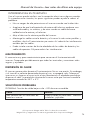
SOLUCIÓN DE PROBLEMAS
PROBLEMA: Tensión de salida baja o nula – LED de error encendido
Causa Solución
Mal contacto con los terminales de
batería o inversor.
Limpie a fondo los terminales. Vuelva a
instalarlos y ajústelos.

Inversor de Energía Slimline
™
de Wagan Tech
®
29
www.wagan.com
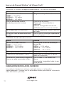
PROBLEMA: El inversor se apaga automáticamente – LED de error encendido
Causa Solución
Tensión de batería inferior a
#3724 — 10 voltios
#3724-4 — 20 voltios
#3724-8 — 40 voltios
Cargue o sustituya la batería.
Inversor demasiado caliente:
(modo de protección térmica)
Deje enfriar el inversor.
Compruebe si la ventilación es
adecuada.
Reduzca la carga del inversor a la
salida de potencia continua nominal.
La unidad puede ser defectuosa. Consulte la garantía y llame a atención
al cliente.
El equipo usado absorbe demasiada
energía.
Use un inversor de mayor capacidad o
no use el equipo.
PROBLEMA: Sonido de timbre continuo
Causa Solución
Tensión de entrada inferior a
#3724 — 10.5 voltios
#3724-4 — 21.0 voltios
#3724-8 — 42.0 voltios
Mantenga la tensión de entrada por
encima de
#3724 — 10.5 voltios
#3724-4 — 21.0 voltios
#3724-8 — 42.0 voltios
Mal estado de batería o batería baja. Recargue o sustituya la batería.
Conexión de cable pobre o suelta. Inspeccione los terminales y apriete
todas las conexiones.
Alimentación inadecuada entregada al
inversor o caída excesiva de tensión.
Use un cable CC de medida más
densa.
Mantenga la longitud del cable lo más
corta posible.
ELIMINACIÓN/RECICLAJE DEL INVERSOR
Los productos electrónicos contienen materiales tóxicos si se desechan
inadecuadamente. Contacte con las autoridades locales para obtener información
sobre eliminación y reciclaje.

Manual de Usuario—Leer antes de utilizar este equipo
© Corporación Wagan 2018. Todos los derechos reservados.
Wagan Tech y wagan.com son marcas registradas de la Corporación Wagan.
30
www.wagan.com
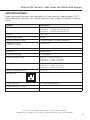
ESPECIFICACIONES
Todas las especificaciones son habituales en línea nominal, media carga y 25ºC
salvo indicación contraria. Las especificaciones están sujetas a cambios sin previo
aviso.
Nombre Descripción
Entrada #3724 — 11-15V entrada de CC
#3724-4 — 21-28V entrada de CC
#3724-8 — 42-56V entrada de CC
Salida 115 V CA
Frecuencia de salida 60 Hz
Forma de onda de salida Forma de onda sinusoidal modificada
TrueRated™ Power
(24 horas continuo)
2,000 vatios
Alimentación de subida 4,500 vatios
Eficiencia Máximo 90%
Corriente sin carga < 1.0 amperios
Alarma de batería baja #3724 — 10.5V ± 0.5V CC
#3724-4 — 21.0V ± 1.0V CC
#3724-8 — 42.0V ± 2.0V CC
Apagado por batería baja #3724 — 9.5V ± 0.5V CC
#3724-4 — 20.0V ± 1.0V CC
#3724-8 — 40.0V ± 2.0V CC
Alarma y apagado térmico 55ºC ± 5º
Enchufes CA
3 NEMA 5-15 EE. UU.
Conexiones USB 2x 3.0A (compartido), 5V
Dimensiones (L x P x A) cm
36.8 × 13.5 × 6.4 (cm)
Peso neto
2.2 kg

Inversor de Energía Slimline
™
de Wagan Tech
®
31
www.wagan.com
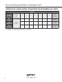
MEDIDAS DE CABLE SEGÚN LONGITUDES DE RECORRIDO DE CABLE
2,000W
Entrada
Longitud
total de
cable
(metros)
2 3 4 5 6 7 8
Fuse*
(Amps)
12V
(#3724)
Calibre
(AWG)
2 2 0 0 00 000 000
250
24V
(#3724-4)
6 4 2 2 0 0 0
120
48V
(#3724-8)
6 6 4 4 2 2 2
60
* Fusible de protección de batería no incluida.

www.wagan.com
La garantía de WAGAN Corporation se limita exclusivamente a los
productos vendidos en Estados Unidos.
Duración de la garantía:
Se extiende la garantía del producto para el comprador original por el periodo de
dos (2) años a partir de la fecha de compra original, que declara que está libre de
defectos de materiales y mano de obra. WAGAN Corporation no asume ninguna
responsabilidad por daños consecuentes. Bajo ninguna circunstancia WAGAN
Corporation asumirá responsabilidad por daños que excedan el importe pagado por
el producto en una tienda minorista.
Cumplimiento de la garantía:
Durante el periodo de la garantía, un producto defectuoso será reemplazado por un
modelo equivalente cuando el producto sea devuelto a WAGAN Corporation con
un recibo original de la tienda. WAGAN Corporation, a su criterio, reemplazará,
reemplazará o reparará la parte defectuosa. El producto de reemplazo quedará
cubierto por el resto del periodo de la garantía original. Esta garantía no se extiende
a las unidades cuyo uso haya violado las instrucciones suministradas por escrito.
Exclusiones de la garantía:
Esta garantía reemplaza toda otra garantía expresa o implícita y ningún representante
o persona están autorizados a asumir responsabilidad alguna en relación con la
venta de nuestros productos. No se aceptarán reclamos por defectos o falla de
funcionamiento o falla del producto bajo ninguna interpretación del derecho de
responsabilidad civil, contractual o comercial, sin limitarse a negligencia, negligencia
grave, responsabilidad objetiva, violación de garantía y violación de contrato.
Devoluciones:
WAGAN Corporation no se responsabiliza por cualquier elemento(s) devuelto(s) sin
un número de Autorización de devolución (#AD). Por favor póngase en contacto con
nuestro equipo de servicio al cliente por teléfono o correo electrónico para obtener un
#AD. También puede visitar nuestro sitio web y hablar con nuestro equipo en nuestro
horario normal de trabajo. Para más detalles e instrucciones sobre cómo procesar
un reclamo de garantía, por favor lea la sección “Devoluciones” de la página de
“Contacto” en nuestro sitio web. WAGAN Corporation no se responsabiliza por
cualquier cargo por envío que resulte de la devolución de el/los elemento(s) a la
compañía para reparaciones o reemplazo.
Registre su producto en línea en http://tinyurl.com/wagan-registration para ser
agregado a nuestra lista de correo electrónico. Recibirá reseñas sobre nuestros
próximos productos, promociones y eventos.
©2015
Garantía Limitada de la Corporación Wagan


31088 San Clemente Street
Hayward, CA 94544, U.S.A.
Tel: +1.510.471.9221
U.S. & Canada Toll Free: +1.800.231.5806
customerservice@wagan.com
www.wagan.com
©2018 Wagan Corporation. All Rights Reserved
Wagan Tech and wagan.com are trademarks used by Wagan Corporation
© Corporación Wagan 2018. Todos los derechos reservados
Wagan Tech y wagan.com son marcas registradas de la Corporación Wagan
REV20180727-ES
-
 1
1
-
 2
2
-
 3
3
-
 4
4
-
 5
5
-
 6
6
-
 7
7
-
 8
8
-
 9
9
-
 10
10
-
 11
11
-
 12
12
-
 13
13
-
 14
14
-
 15
15
-
 16
16
-
 17
17
-
 18
18
-
 19
19
-
 20
20
-
 21
21
-
 22
22
-
 23
23
-
 24
24
-
 25
25
-
 26
26
-
 27
27
-
 28
28
-
 29
29
-
 30
30
-
 31
31
-
 32
32
-
 33
33
-
 34
34
-
 35
35
-
 36
36


Wagan SlimLine AC Inverter 2000 Watt Manual de usuario
- Categoría
- Adaptadores de corriente
- Tipo
- Manual de usuario
En otros idiomas
Documentos relacionados
-
Wagan SlimLine AC Inverter 250 Watt Manual de usuario
-
-
-
-
-
-
-
-
-
Otros documentos
-
 Pooxtra PXA3000MSW Manual de usuario
-
Solar PI10000X Manual de usuario
-
Sunforce 11260 Manual de usuario
-
GYS INVERTER MSW82000 - 24V (2000W MODIFIED WAVE) Ficha de datos
-
-
 Xantrex PROwatt SW Guía del usuario
-
 Eltek Valere Theia He-t Guía de instalación


