Pooxtra PXA3000MSW Manual de usuario
- Categoría
- Adaptadores de corriente
- Tipo
- Manual de usuario

Please read this manual carefully before operation
Lea detenidamente este manual antes de utilizarlo
Email:support@pooxtra-inverter.com
www.pooxtra-inverter.com
Pooxtra All Rights Reserved
Pure Sine Wave
Power Inverter
Inversor de potencia
de onda sinusoidal
pura
Inversor de potencia
de onda sinusoidal
modificada
PXA500PSW
PXA1000PSW
PXA1500PSW
PXA2000PSW
PXA3000PSW
Modified Sine Wave
Power Inverter
PXA1000MSW
PXA2000MSW
PXA3000MSW
User’s Manual
Page 1 to Page 22)
Manual de Usuario
(Página 23 a Página 45)
TM
US Edition-A1711-1

THANK YOU FOR SHOPPING WITH US
We hope you are enjoying your new purchase.
At , we pride ourselves in the high quality and design of all our products.
We want you to know that your thoughts and comments are very important to us, it is
also the key to the future success of our brand. Please consider leaving a review on
our product page so that others may benefit from your personal experience.
IF FOR ANY REASON YOU ARE NOT SATISFIED WITH YOUR ITEM
OR IF YOU HAVE ANY QUESTIONS, PLEASE DON'T HESITATE TO CONTACT
CUSTOMER SUPPORT AT SUPPORT@POOXTRA-INVERTER.COM AND WE
WILL DO WHATEVER IT TAKES TO EARN YOUR SATISFACTION .
TM
QUALITY WARRANTY:
Register your product at
www.pooxtra-inverter.com
TM
Contact
Information
After-Sales Service Phone :
(818) 658-9690
Email (Technical Issues)
support@pooxtra-inverter.com
Email (Wholesale & Retail)
sales@pooxtra-inverter.com
Official Website
www.pooxtra-inverter.com
USA Shipping Warehouse
Flushing NY
Scan to connect with us.
https://www.facebook.com/Pooxtra
https://twitter.com/PooxtraInverter
Like Us Follow Us

Welcome
Please read this manual thoroughly before installing and operating
your new Pooxtra Power Inverter. This manual contains information
you need to obtain the performance required for your application.
Keep this manual for future reference.
A Higher Wattage Inverter May Be Required
To determine whether the Pooxtra inverter will operate a particular
appliance or a combination of appliances, run a test. All inverters are
designed to automatically shut down in the event of a power overload.
This protection feature prevents damage to the unit while testing
appliances. Turn on the highest wattage appliance first then other
appliances. If an appliance will not operate properly, then it is likely
that this Pooxtra inverter does not have the required capacity to
operate the appliance in question.
WARNINGS, CAUTIONS AND NOTES
It is very important that any operator and installer of this inverter read
and follow all WARNINGS, CAUTIONS AND NOTES and all installation
and operation instructions. In particular, comply with WARNINGS
(possibility of serious injury or death), CAUTIONS (possibility of
damage to the inverter and / or other equipment), and NOTES
(included to assist you in achieving the maximum performance and
longest working life from this advanced-design inverter).
This Pooxtra Inverter converts low voltage, direct current (DC) to
120v alternating current (AC). The inverter draws power from 12 volt
deep cycle batteries such as those used for marine, golf cart, and
fork lift or from other high current 12 volt sources.
www.pooxtra-inverter.com 1
TM

TO REDUCE THE RISK OF FIRE, ELECTRIC SHOCK, EXPLOSION OR INJURY
IMPORTANT SAFETY INSTRUCTIONS
1. Do not connect to AC distribution wiring. This inverter is NOT grid interactive.
2. Remove appliance plug from outlet strip or turn off inverter before working
on the appliance. Multiple outlet power strips with switches and circuit
breakers only interrupt power to the “hot” receptacle terminals.
3. Do not make any electrical connections or disconnections in areas
designated as IGNITION PROTECTED.This includes 12 V DC cigarette
plug connections, and terminal connections.
4. This is not a toy - keep away from children.
5. DO NOT insert object into air vents.
• Keep the inverter away from any direct heat source or combustible materials.
• Keep well ventilated—this device generates heat.
• Keep this inverter in a dry environment.
• Do not attempt to connect the inverter to any other power source,
includingany AC power source.
• Incorrect battery polarity will damage the inverter and void the warranty.
• Do not open the inverter; there are no user serviceable parts inside.
Pooxtra All Rights Reserved
Pooxtra and pooxtra-inverter.com are trademarks used by Pooxtra Global LLC.
2
WARNINGS
1. Observe correct polarity when connecting the DC input terminals of the
inverter to the battery. Connect Positive of the battery to the Positive input
connector of the inverter and the Negative of the battery to the Negative
input terminal of the inverter. Reverse polarity connection will result in a blown
fuse and may cause permanent damage to the inverter. Damage due to
reverse polarity is not covered under warranty.
2. This inverter will not operate high wattage appliances that exceed the
output power limit or the surge power limit.
3. Do not operate this inverter if it is wet.
4. Do not install in engine compartment – please install in a well ventilated area.
5. This inverter is not tested for use with medical devices.
CAUTIONS
INVERTER OUTPUT CAN BE LETHAL. IMPROPER USE
OF THIS INVERTER MAYRESULT IN PROPERTY DAMAGE,
PERSONAL INJURY OR LOSS OF LIFE.

www.pooxtra-inverter.com 3
TM
HOW YOUR INVERTER WORKS
Substantial power loss and reduced battery operating time results from inverters
installed with wires that are not sized correctly based on the length and the current
required to be carried. Current flowing through a wire produces voltage drop along
its length due to the resistance of the wire and due to the value of the currentcarried
through it. The resistance of the wire is inversely proportional to the cross-sectional
area of the wire (designated in mm2 or AWG) and directly proportional to its length
i.e. thinner and longer wire has higher resistance and hence, produces higher
voltage drop. Similarly, thicker and shorter wire has lower resistance and hence,
produces lower voltage drop. Hence, symptoms of low DC input voltage / battery
power can result from wires that are either excessively long or have an insufficient
cross-sectional area (designated in mm2 or AWG).
The wires should be sized based on the maximum current they are required
to carry and the distance between the battery and the inverter to limit the
voltage drop to 2% to 5%.
Wires are rated based on its insulation, temperature and operating environment.
Please ensure that the wire insulation is of the appropriate type for the operating
environment.
The installer/operator should be especially aware of the requirements to maintain
secure, tight, water-resistant electrical connections and to provide for strain relief
for DC wires and appliance wiring.
The inverter converts low voltage DC (Direct Current) from a battery or other
DC power source to the standard nominal 120 volt AC (Alternating Current)
household power.
IMPORTANT WIRING INFORMATION
• High Efficiency
• Compact Size
• Low Idle Current
• Soft Start Technology
• MCU LED DISPLAY
• Wired Remote Control (for 1000/1500/2000/3000W)
DESIGN FEATURES

Pooxtra All Rights Reserved
Pooxtra and pooxtra-inverter.com are trademarks used by Pooxtra Global LLC.
4
The continuous power ratings of the models are as follows:
• PXA500PSW — 500 Watts
• PXA1000PSW/1000MSW — 1000 Watts
• PXA1500PSW — 1500 Watts
• PXA2000PSW/2000MSW — 2000 Watts
• PXA3000PSW/3000MSW — 3000 Watts
DESIGN FEATURES
The inverter converts power in two stages. The first stage is a DC to DC conversion
process that raises the low voltage DC at the inverter input to high voltage DC of
approximately 150VDC. The second stage is the actual inverter stage that converts
the high voltage DC into nominal 120 VAC, 60 Hz AC (RMS). The DC-to-DC
converter stage uses modern high frequency power conversion techniques that
have replaced the bulky transformers found in less technologically-advanced models.
The inverter stage uses advanced IGBT transistors in a full bridge configuration.
PRINCIPLE OF OPERATION
THE OUTPUT WAVEFORM
The AC output waveform of the PSW-series inverter is known as “Pure Sine Wave”
or “True Sine Wave”. It is a waveform that has characteristics same to the sine
wave shape of utility power (See Fig. 1).
The AC output waveform of the MSW-series inverter is known as “Modified Sine
Wave” . It is a waveform that has characteristics as below. (See Fig. 2).
Fig.1. Pure Sine Wave Waveform Fig.2. Modified Sine Wave Waveform
1.0 1.0
- 1.0
0.5
- 0.5
- 6 - 4 - 2 642
- 1.0
0.5
- 0.5
- 6 - 4 - 2 642

www.pooxtra-inverter.com 5
TM
INSTALLATION / ENVIRONMENTS
• Power Switch — This switch controls AC output of the inverter.
• AC Outlets —
These outlets can supply up to 8 amps at 120V AC 60 Hz (for 1000Watts) ;
12.5 amps at 120V AC 60 Hz (for 1500Watts) ;
15 amps at 120V AC 60 Hz (for 2000Watts)
• USB Power Ports — These power ports can supply 5 volts at 2.1A for charging
or powering tablets, e-readers, smartphones, and other small electronic devices.
• Ground Terminal — For attaching an insulated safety ground wire. This safety
wire is for protecting personnel if there is an unlikely failure in either the cabling
or enclosure insulation. Grounding the inverter enclosure ensures personnel
safety should a DC cable problem occur. During the installation procedure, the
Ground Terminal is connected either to a vehicle chassis or to the negative DC
terminal of the battery. Do not directly connect this ground connection to the
negative DC terminal of the inverter. If the inverter installation is located in fixed
location, the safety wire can be connected to earth’s ground.
• Remote Control — Wired remote ON/OFF control (See Remote Control Below).
FRONT PANEL
USB Power Ports
AC Outlets
Power Switch Remote Control
Ground Terminal
PXA1000PSW/1000MSW/1500PSW/2000PSW/2000MSW

Pooxtra All Rights Reserved
Pooxtra and pooxtra-inverter.com are trademarks used by Pooxtra Global LLC.
6
• Power Switch — This switch controls AC output of the inverter.
• AC Outlets — These outlets can supply up to 15 amps at 120V AC 60 Hz
• AC Terminal Block — This Hard Wire Direct Connecting can supply up to 25
amps at 120V AC 60 Hz .
(Inverter’s full power is available through this AC Terminal Block)
• USB Ports — These power ports can supply 5 volts at 2.1A for charging
or powering tablets, e-readers, smartphones, and other small electronic devices.
• Ground Terminal — For attaching an insulated safety ground wire. This safety
wire is for protecting personnel if there is an unlikely failure in either the cabling
or enclosure insulation. Grounding the inverter enclosure ensures personnel
safety should a DC cable problem occur. During the installation procedure, the
Ground Terminal is connected either to a vehicle chassis or to the negative DC
terminal of the battery. Do not directly connect this ground connection to the
negative DC terminal of the inverter. If the inverter installation is located in fixed
location, the safety wire can be connected to earth’s ground.
• Remote Control — Wired remote ON/OFF control (See Remote Control Below).
FRONT PANEL
USB PortsAC Outlets
Power
Switch
Remote Control
AC Terminal Block (Hard Wire Connecting)
Ground Terminal
PXA3000PSW/3000MSW

www.pooxtra-inverter.com 7
TM
• Power Switch — This switch controls AC outpu t of the inverter.
• AC Outlets — These outlets can supply up to 4 amps at 120V AC 60 Hz.
• USB Ports — These power ports can supply 5 volts at 2.1A for charging
or powering tablets, e-readers, smartphones, and other small electronic devices.
FRONT PANEL
Power Switch
USB Ports
AC Outlets
PXA500PSW
REMOTE ON/OFF CONTROL (Excluding Model PXA500PSW)
ON/OFF
Button
This inverter is supplied with a 9.8Ft(3m) length
wired On/Off remote control. To enable the Remote
Switch, the Front Panel Power Switch of the inverter
must be OFF. To turn on the inverter, momentarily
press the ON button. To turn the inverter off,
momentarily press the OFF button.

Pooxtra All Rights Reserved
Pooxtra and pooxtra-inverter.com are trademarks used by Pooxtra Global LLC.
8
• Positive Terminal — Positive (+) DC Input (Red)
• Negative Terminal — Negative (−) DC Input (Black)
• Cooling Fan — High-Speed Cooling Fan. When the temperature inside the
inverter exceeds a preset limit, the Cooling Fan automatically turns on to
cool the inverter. When the temperature reduces, the fan turns off.
REAR PANEL Excluding Model PXA500PSW)
Negative (-) Terminal [Black] Cooling Fan
Positive (+) Terminal [Red]
• Positive Terminal — Positive (+) DC Input (Red)
• Negative Terminal — Negative (−) DC Input (Black)
• Cooling Fan — High-Speed Cooling Fan. When the temperature inside the
inverter exceeds a preset limit, the Cooling Fan automatically turns on to
cool the inverter. When the temperature reduces, the fan turns off.
REAR PANEL PXA500PSW)
Cooling Fan
Positive (+) Terminal [Red]Negative (-) Terminal [Black]

www.pooxtra-inverter.com 9
TM
1. Battery Level Bar -
a. Green means full level b. Yellow means half level
c. Red means low input, you have to recharge the battery at once
2. Load Level Bar -
a. Red means the inverter is almost overloaded ,not available for more loads
b. Yellow means half level of loads but still acceptable
c. Green means working in good condition (low loads without worries)
3. Input Voltage Display
4. Output Voltage Display
5. High Temperature Warning Indicator -
The symbol of lights up (red color) ,plus audible alarm then shutdown
6. High/Low Input Voltage Warning Indicator -
a. High input voltage warning - symbol of lights up(red), battery level bar
flickers,input voltage display shows 14.5V or more,plus audible alarm then shutdown
b. Low input voltage warning - symbol of lights up(red), battery level bar
flickers,input voltage display shows 10.5V or less,plus audible alarm then shutdown
7. Overload / Short-circuit Warning Indicator -
a. Overload warning - symbol of lights up(red), load level bar flickers, no
outputplus audible alarm ,then shutdown
b. Short circuit warning - same as above
8. Frequency Display
9. Power On/Off Indicator -
a. Green - working
b. Red - faulty, without output
MCU LED DISPLAY DIAGRAM
-+
t
t
v
v
v
v
BATTERY
3
4
5
789
1 2
6

Pooxtra All Rights Reserved
Pooxtra and pooxtra-inverter.com are trademarks used by Pooxtra Global LLC.
10
There are two DC power sources (12V and 24V) for Pooxtra inverter, please check
it carefully before you buy. The input voltage range will be stated in the Specfication
Sheet . The DC power source must be able to supply the necessary current to
operate the load. The power source may be a battery or a well-regulated DC power
supply. To obtain a rough estimate of the current (in Amperes) the power source
must deliver,simply divide the power consumption of the load (in Watts AC) by 10 .
(The calculatingis provided you are using 12V DC power source).
Example: if a load is rated at 100 Watts AC, the DC power source must be able to
deliver: 100 / 10 = 10A.
The inverter will provide you nominal 120 VAC when powered by a 12 VDC source
such as is found in a vehicle or multiple battery configurations as shown in fig. 3.
This manual does not describe all of the possible types of battery configura-
tions, battery charging configurations and battery isolation configurations.
For normal operation of the inverter, the DC power source must provide between
11.0 and 14.0 VDC(for 12V INPUT ) and the required current. This DC power
sourcemust be a well-regulated DC power supply or alternator and deep cycle
battery system typically found in vehicles and marine crafts. The DC power source
may also be two or more 12 volt batteries connected in parallel. on larger applications,
the power source may be several batteries connected in parallel as shown in fig. 3.
DC POWER SOURCE REQUIREMENTS

www.pooxtra-inverter.com 11
TM
WARNING: Ensure ventilation when using batteries. Batteries may generate
flammable gas during charging or discharging.
The inverter has four mounting holes in its mounting bracket that allow the unit to
be fastened against a bulkhead, floor, wall or other flat surface. Ideally, the mounting
surface should be cool to the touch. It is more electrically efficient to use longer AC
wiring than DC wiring, so install the inverter as close as possible to the DC power source.
The inverter can be operated in any position, however, if it is to be mounted on a
wall, mount it horizontally (fig 4a) so that LED dispaly ,switches, outlets and terminal
blocks located on the front panel are visible and accessible. Do not mount on wall
in positions shown in figs. 4 (b) & 4(c). If the inverter is to be installed in a moving
vehicle, we strongly recommend that the inverter be shock-mounted either on the
floor (in a clear, safe area) or on a secure flat surface.
INSTALLATION NOTES
The power inverter must be connected only to batteries with a nominal output
voltage of 12 V. The unit will not operate from a 6 Volt battery, and will sustain
permanent damage if connected to a 24 V battery.
CAUTION (For 12V DC INPUT Inverter)
Loose connectors may cause overheated wires and melted insulation. Check to
make sure you have not reversed the polarity. reverse polarity connection will result
in a blown fuse and may cause permanent damage to the inverter.
Damage due to reverse polarity is not covered by warranty.
CAUTION

Pooxtra All Rights Reserved
Pooxtra and pooxtra-inverter.com are trademarks used by Pooxtra Global LLC.
12
Please ensure that the DC side wires and external fuses are selected as given below.
Note that an external fuse is required to protect the battery wires from short circuit. A battery
is an unlimited source of current and can deliver extremely high (up to 10,000 A of current)
into a short circuit that will melt the wires and cause fire hazard.
Current limiting fuse with Ampere Interrupting Capacity (AIC) of 10000 A or more or
Class T fuse is, therefore, recommended.
CONNECTING TO A DC POWER SOURCE
1. Ensure that appropriate terminal lugs are used and are properly crimped / soldered
at the bare ends of the wires for secure connections.
2. Ensure that the inverter’s power switch is turned off and that no flammable fumes are present.
3. Identify the Positive (+) and Negative (-) terminals of the 12 V battery or other DC source.
4. Install a fuse holder or breaker close to the Positive (+) terminal of the battery
(or other DC source) (preferably within 7” of the terminal) .
5. Cut an appropriate short piece of the selected Positive wire and use this to piece to
connect the Positive terminal of the battery (or other DC source) to one terminal of
the fuse holder or breaker. Connect one end of the remaining length of wire to the
other terminal of the fuse holder or breaker. Connect the other end of the wire to the
Positive terminal of the inverter.
6. Connect the selected length of Negative wire between the Negative terminal of the
battery (or other DC source) and the Negative (-) terminal of the inverter.
7. Insert a suitable fuse in the fuse holder.
8. Check to be sure that all connections are secure and tight.
9. Test the inverter by turning it on and plugging in a 100 Watt lamp or equipment.
10. If the inverter is not properly operating, then refer to the Troubleshooting Guide at
the end of this manual.
CAUTION: Loose connectors may cause overheated wires and melted insulation.
MAKING DC SIDE CONNECTIONS
External FUSE and DC wire selection
Note: The DC cable coming with Pooxtra inverter may not match the below wire size
Note:
The type of batteries you use to power your high power inverter is important. Operating a
high power inverter will routinely discharge batteries and they will require frequent recharging.
Batteries used to start engines are not designed to repeatedly charge and discharge.
Pooxtra recommends using “deep-cycle” or “marine” rated batteries.
→ → →

www.pooxtra-inverter.com 13
TM
Please ensure that the following procedure is used for switching on and switching
off the inverter when a load is already connected to the inverter:
1. Switch off the load connected to the inverter
2. Switch on the inverter
3. Wait for a few seconds
4. Switch on the load
SWITCHING ON AND SWITCHING OFF ON LOAD
1. Make sure that the single load or the combined load requirement of your
equipment does not exceed theinverter’s output rating.
2. Switch off the inverter
3. Switch off the load
4. Plug the cord(s) from the load(s) into the AC receptacle(s) of the inverter
5. Switch on the inverter. Wait for a few seconds
6. The LED display will be working to indicate that the inverter is functioning
7. Switch on the load(s)
The inverter is engineered to be connected directly to standard electrical and
electronic equipment in the manner described above. Do not connect the power
inverter to household or RV AC distribution wiring. Do not connect the power
inverter to any AC load circuit in which the Neutral conductor is connected to
Ground (Earth) or to the Negative of the DC (battery) source.
WARNING: Do not connect directly to AC distribution wiring. This inverter is
NOT grid interactive.
CONNECTING LOADS
Switching on
1. Switch off the load connected to the inverter
2. Switch off the inverter
Switching off
For best operating results, the inverter should be placed on flat surface, such as the
ground, car floor, or other solid surface. The power cord allows easy positioning of the
inverter. The inverter should only be used in locations that meet the following criteria:
Do not allow water and/or other liquids to come into contact with the power inverter.
In all marine applications, do not install the inverter below or near the waterline and
keep the inverter away from moisture or water.
OPERATING ENVIRONMENT
DRY
Ambient air temperature should be between 30 degrees F (-1 degree C) non-
condensing, and 105 degrees F (40degrees C). Do not place the inverter on or near
a heating vent or any piece of equipment which is generating heat above room
temperature. Keep the inverter away from direct sunlight, if at all possible.
COOL

Pooxtra All Rights Reserved
Pooxtra and pooxtra-inverter.com are trademarks used by Pooxtra Global LLC.
14
The unit is cooled by load controlled fan (s). The fan(s) will be normally switched off
at low loads to conserve battery power and will be switched on automatically once
the load reaches a certain threshold. Keep the area surrounding the inverter clear
to ensure free air circulation around the unit. Do not place items on or over the
inverter during operation. An additional external fan is helpful if the inverter is operating
at maximum power outputs for extended periods of time. The unit will shut down if
the internal temperature exceeds the operating temperatures. The unit will restart
after it cools.
VENTILATED
Do not use the inverter near flammable materials or in any locations that may
accumulate flammable fumes of gases.
SAFE
Most electrical tools, appliances and audio/video equipment have labels that indicate
the power consumption in Amps or Watts. be sure that the power consumption of
the item you wish to operate is less than inverter’s power. (If the power consumption
is rated in Amps AC, simply multiply by the AC Volts (120V) to determine the
approximate Wattage). The inverter will shut down if it is overloaded. The overload
must be removed before the inverter will restart. Resistive loads are the easiest for
the inverter to run. However, larger resistive loads,such as electric stoves or heaters,
usually require more wattage than the inverter can deliver.Inductive loads,such as
TV’s and stereos, require more current to operate than do resistive loads of the
same wattage rating.Induction motors, as well as some televisions, may require 2
to 6 times their wattage rating to start up. The most demanding in this category are
those that start under load, such as compressors and pumps. To restart the unit
after a shutdown due to overloading, remove the overload if necessary turn the
power switch OFF, wait for at least 3 minutes and then switch ON again.
RATED VERSUS ACTUAL CURRENT DRAW OF EQUIPMENT
The manufacturers’ specifications of the appliances and devices indicate only the
running power required.
The surge power required by some specific types of devices has to be checked
with the manufacturer, actually tested or guessed at best.
The Table below lists some common loads that require high surge power on start
up. A “Sizing factor” has been recommended against each which is a Multiplication
factor to be applied to the rated running Watt rating of the load to arrive at the
continuous power rating of the inverter (Multiply the running Watts of thedevice /
appliance by the Sizing factor).
SIZING CHART FOR TYPICAL LOADS THAT REQUIRE
HIGH STARTING SURGE
OPERATING TIPS

www.pooxtra-inverter.com 15
TM
* In the case of photographic strobe / flash unit, the RMS surge power of the
inverter should be more than 4 times the Watt Sec rating of the unit.
The power inverter will require DEEP CYCLE lead acid batteries of appropriate
capacity.The automotive SLI (Starting/lighting/Ignition) battery is not designed
for repeated deep discharge. The SLI battery may not supply enough energy
and its service life may be reduced.
To determine the minimum battery size that you will need to operate appliances,
follow these steps:
1. Determine the AC wattage of each appliance and / or tool you will need to
simultaneously operate from the inverter. To do this, read the labels on the
equipment to be operated. Usually, power consumption is shown in Watts. If it is
shown in Amps, multiply by 120 to determine the AC wattage.
2. For each appliance, estimate the number of hours the appliance will be in use
between battery recharges.
3. For each appliance, determine the Watt-Hours of energy required by multiplying
the AC wattage by the number of hours of use.
4. Add the Watt-Hours of energy for each appliance to get the total Watt-Hours of
energy for all appliances to be used.
5. Divide the total Watt-Hours of energy on the AC side by 10 to get the total Ampere-
Hour of energy on the 12 VDC side to support the operation of the appliances.
6. The Ampere-Hour (AH) capacity of the battery should be 2 times the total
Ampere-Hour energy required on the 12 VDC side to support the operation of the
devices (as calculated at step 5 above). Two times factor is necessary because
batteries are normally not discharged below 50% capacity.
DETERMINING BATTERY SIZE

Pooxtra All Rights Reserved
Pooxtra and pooxtra-inverter.com are trademarks used by Pooxtra Global LLC.
16
To get an estimate of the current (in Amps) that the battery is delivering, divide the
load's AC consumption power (in Watts) by (10).
Keep in mind that most appliances are not operating for long periods of time. for
example, a typical home use coffee maker draws 500 Watts during its brew time
of 5 minutes, but it maintains the temperature of the pot at about 100 Watts.
Typical use of a microwave is only for a few minutes, sometimes at low power.
Some exceptions to brief operating times are TVs, computers etc.
In most instances, the inverter can be left connected to the battery when not in use,
make sure power switch is in the OFF position.
Battery performance drops in low temperature environment. Higher capacity
batteries should be installed if the environmental temperature is below 20.
The unit is cooled by temperature controlled fan(s). The fan(s) will run at full speed
when the interior inverter temperature goes over 50. In case the fan fails or if the
cooling is inadequate due to higher ambient temperature or restricted air flow, the
temperature inside the inverter will be too high and the unit will automatically shut
down. Allow the unit to cool for at least 15 minutes before restarting after a heat-
related shutdown. Unplug unit while cooling.
OVER TEMPERATURE PROTECTION
This condition is not harmful to the inverter but could damage the power source.
The inverter automatically shuts down when input voltage drops to 10 Volts.
(For 12V DC Input )
LOW BATTERY VOLTAGE PROTECTION
The inverter will automatically shut down when the input voltage exceeds 15 Volts
DC.Input voltage exceeding 16 Volts could damage the inverter.(For 12V DC Input)
OVER VOLTAGE PROTECTION
The inverter will automatically shut down when the continuous draw exceeds rated Watts.
OVERLOAD PROTECTION
The inverter will shut down. Remove the short circuit and restart inverter.
SHORT CIRCUIT PROTECTION
This inverter complies with the standard current leakage allowance. When large
current leakage to earth terminal occurs, the protection circuit activates and shuts
down the inverter,which prevents electric shock to humans. Turn OFF the inverter,
unplug the fault AC appliance and then turn ON is the only way to restart it.
EARTH FAULT PROTECTION
PROTECTIVE FEATURES OF THE INVERTER

www.pooxtra-inverter.com 17
TM
An alarm will sound when the voltage at the input terminals of the inverter drops to
10.5 Volts.(For 12V DC Input )This is an indication that either the battery terminal
voltage has dropped due to its discharged condition and needs to be recharged or
there is an excessive voltage drop across the wires connecting the inverter to the
battery (due to use of thinner and longer length of wires that will produce higher
voltage drop at higher loads or due to loose connections). The user should stop
operation of the electronic device at this time since the inverter will shut down
automatically shortly thereafter, when the input voltage at the inverter further drops
to 10 Volts. In case the alarm is due to the discharged condition of the battery, start
your engine to recharge the battery /use an appropriate battery charger.
If the low voltage alarm sounds when the battery is fully charged, follow the steps for
solving lack of output power in the Troubleshooting Guide at the end of this manual.
NOTE: It is normal for the alarm to sound while the unit is being connected
to or disconnected from the power source. This is not indicative of a problem.
LOW INPUT VOLTAGE ALARM
TROUBLESHOOTING GUIDE
TROUBLE / SYMPTOMS
NO AC OUTPUT Over Temperature Shutdown
On the LED Display
• Symbol lights up
(Red Color)
• Symbol lights up
(Red Color)
• AC output voltage is being
displayed ”0”
• Load Level Bar is OFF
• There is a buzzer alarm
In case the fan fails or if the cooling
is inadequate due to higher ambient
temperature or restricted airflow,
the temperature inside the inverter
will start rising. Temperature rise
is sensed at one of the DC side
Mosfets. If this temperature
exceeds 80 , the AC output will
be switched off.
No activity due to loss of DC
input power to the inverter
1. If there is no voltage at the DC
input terminals:
• Battery is dead
• External DC input fuse is blown
• Loose connection along the
circuit from the battery to the
DCinput terminals
2. If there is voltage at the DC
input terminals:
• Internal DC input fuses
have blown
1. The inverter will remain
latched inthis shut down
condition and will be required
to be reset manually by
switching OFF, waiting for
15 minutes and switching
ON again.
2. Before using the inverter again,
please ensure that the cause
of over temperature has
been removed
1. Check DC side wire
connections and fuses or
contact Technical Support
NO AC OUTPUT
• LED Display is OFF
• There is no buzzer alarm
POSSIBLE CAUSE(S) SUGGESTED REMEDIES
t

Pooxtra All Rights Reserved
Pooxtra and pooxtra-inverter.com are trademarks used by Pooxtra Global LLC.
18
TROUBLE / SYMPTOMS
Shut down due to overload or
short circuit
Inverter has shut down because
the power drawn by the load is
more than the continuous / surge
ratings or thereis a short circuit on
the load side.
1. Reduce the load or disconnect
the load that is causing
overloading.
2. Check for shorting and remove
the short.
3. When the inverter shuts down
due to overload, it will be
latched in shutdown condition
and will require a manual reset
at the inverter by switching off
and then switching on. Switch
OFF the inverter. Wait for 3
min for the internal latching
circuit to deenergize and then
switch ON again after
removing the cause of
overload / short circuit
4. NOTE: for the models with
Remote Control cannot be
reset by using the ON / OFF
push button on the remote.
Manual reset, as explained
above, has to be carried out
with the help of the ON / OFF
switch on the inverter
NO AC OUTPUT
POSSIBLE CAUSE(S) SUGGESTED REMEDIES
Shutdown due to low DC
input voltage
1. DC input wire size is not
adequate for the capacity of
the AC load or there is loose
connection between the
battery and the inverter
leading to DC input voltage
falling below the Low DC
Input Voltage Shutdown
Threshold of 10.5V +/- 0.3V
2. The battery has developed
sulfation due to under
charging. In this condition,
the internal resistance of
the battery rises above
normal and hence causes
abnormal voltage drop on
its terminals at higher
discharge current consumed
by higher capacity load
1. Use thicker wires between
the battery and the inverter
and tighten all DC input
circuit connections
2. Check internal resistance of
the battery and remove
sulfation by equalizing the
battery or replace the battery
NO AC OUTPUT
On the LED Display
• Symbol lights up
(Red Color)
• Symbol lights up
(Red Color)
• AC output voltage is being
displayed ”0”
• Load Level Bar is flashing
• There is a buzzer alarm
On the LED Display
• Symbol lights up
(Red Color)
• Symbol lights up
(Red Color)
• AC output voltage is being
displayed ”0”
• Battery Level Bar turns
Red and flashing
• There is a buzzer alarm
• DC input voltage is being
displayed and has dropped
to Low DC Input Voltage
Shut-down Threshold of
10.5V +/- 0.3V
v

www.pooxtra-inverter.com 19
TM
Shutdown due to high DC input voltage
DC input voltage has risen to High
DC Input Voltage Shutdown
Threshold of 15.2V +/- 0.3V
1. Switch off the AC load and the
inverter.
2. Disconnect the DC input to the
inverter
3. Check the output voltages of the
battery and charging source and
ensure these are below the High
DC Input Voltage Shutdown
Threshold of 15.2V +/- 0.3V
4. Check that a 24V battery is not
being used instead of 12V battery
5. The unit will reset automatically
once the voltage drops to
14.6V +/- 0.2V
6. CAUTION! Voltage input of > 16 V will
permanently damage the inverter
NO AC OUTPUT
TROUBLE / SYMPTOMS
AC OUTPUT IS AVAILABLE
On the LED Display
• Buzzer alarm sounds when DC
input voltage drops to Low DC
Input Voltage Alarm Threshold of
10.5V +/-0.2V when delivering
high power loads or even on
low AC loads
• Battery Level Bar turns Red
and flashing
• DC input voltage shows
10.5V+/-0.2V
Buzzer alarm due to intermittent high
AC loads or even at low AC loads
1. DC input wire size is not adequate
for higher capacity loads or there
is loose connection between the
battery and the inverter leading to
DC input voltage falling below the
Low DC Input Voltage Alarm
Threshold of 10.5V +/- 0.2V
2.The battery has developed sulfation
due to undercharging. In this condition,
the internal resistance of the battery
rises above normal and hence causes
abnormal voltage drop on its terminals
at higher discharge current consumed
by higher capacity load
3.The battery is almost discharged
1. Use thicker wires between the
battery and the inverter and tighten
all DC input circuit connections
2. Check internal resistance of the
battery and remove sulfation by
equalizing the battery or replace
the battery
3. Recharge the battery
POSSIBLE CAUSE(S) SUGGESTED REMEDIES
The ON / OFF switch on the
inverter is in ON condition
When using the remote Control ,ensure
that the ON / OFF switch on the inverter
is in OFF position
If appliance does not start, then the
appliance is drawing excessive
power and will not work with the
inverter
Make the load not purely inductive.
operate an incandescent lamp at the
same time as the motor. This will
reduce the reactive power and raise
the Power factor so that the Soft
Start Circuit is not activated
Excessive start-up current from the
load is activating the Soft Start Circuit
and is reducing the output voltage and
consequently the current to a level
where the starting torque required by
the motor is not sufficient to turn the
motor. (Starting torque in a motor is
proportional to Voltage and the Current)
Purely inductive load with higher
reactive power and lower Power
factor is activating the soft start
circuitry and reducing the output
voltage resulting in reduced speed
INVERTER DOES NOT SHUT DOWN
WHEN REMOTE CONTROL
IS SWITCHED OFF
MOTORIZED POWER TOOL
WILL NOT START
MOTORIZED POWER TOOL
DOES NOT OPERATE AT
CORRECT SPEED
On the LED Display
• Symbol lights up (Red Color)
• Symbol lights up (Red Color)
• AC output voltage is being
displayed ”0”
• Battery Level Bar is lit completely
and flashing
• There is a buzzer alarm
• DC input voltage is being displayed
and has risen to High DC Input
Voltage Shutdown Threshold of
15.2V +/- 0.3V
v

Pooxtra All Rights Reserved
Pooxtra and pooxtra-inverter.com are trademarks used by Pooxtra Global LLC.
20
The AC side of this inverter is protected by an integral electronic overload circuit and will
automatically reset in some cases.
More than that, this inverter is equipped with a DC side fuses that are located inside the
inverter. Normally, these fuses will not blow unless a serious problem occurs.
Please DO NOT replace the fuses yourself. We recommend you contact technician to find
and fix the problems. High voltage and high temperature inside! (Please write email to us
whenever you have problems at support@pooxtra-inverter.com)
CAUTION: NO USER-SERVICEABLE COMPONENTS INSIDE.
DO NOT ATTEMPT TO OPEN THE INVERTER.
FUSES INSIDE THE INVERTER
FUSE REPLACEMENT
Pooxtra inverters are manufactured by Pooxtra Global LLC. (the “Warrantor“) are warranted
to be free from defects in workmanship and materials under normal use and service. The
warranty period is one year for the United States, and is in effect from the date of purchase
by the user (the “Purchaser“).
Warranty outside of the United States is limited to 6 months. for a warranty claim, the
Purchaser should contact the place of purchase to obtain a return Authorization Number.
The defective part or unit should be returned at the Purchaser’s expense to the authorized
location. A written statement describing the nature of the defect, the date of purchase, the
place of purchase, and the Purchaser’s name, address and telephone number should also
be included.
If upon the Warrantor’s examination, the defect proves to be the result of defective material
or workmanship, the equipment will be repaired or replaced at the Warrantor’s option without
charge,and returned to the Purchaser at the Warrantor’s expense. (Contiguous US only)
No refund of the purchase price will be granted to the Purchaser, unless the Warrantor is
unable to remedy the defect after having a reasonable number of opportunities to do so.
Warranty service shall be performed only by the Warrantor. Any attempt to remedy the
defect by anyone other than the Warrantor shall render this warranty void. There shall be no
warranty for defects or damages caused by faulty installation or hook-up, abuse or misuse
of the equipment including exposure to excessive heat, salt or fresh water spray, or water
immersion.
No other express warranty is hereby given and there are no warranties which extend beyond
those described herein. This warranty is expressly in lieu of any other expressed or implied
warranties, including any implied warranty of merchantability, fitness for the ordinary purposes
for which such goods are used,or fitness for a particular purpose, or any other obligations
on the part of the Warrantor or its employees and representatives.
There shall be no responsibility or liability whatsoever on the part of the Warrantor or its
employees and representatives for injury to any persons, or damage to person or persons,
or damage to property, or loss of income or profit, or any other consequential or resulting
damage which may be claimed to have been incurred through the use or sale of the
equipment, including any possible failure of malfunction of the equipment, or part thereof.
The Warrantor assumes no liability for incidental or consequential damages of any kind.
Pooxtra Global LLC (the “Warrantor”)
ONE YEAR LIMITED WARRANTY WARRANTY

www.pooxtra-inverter.com 21
TM
* All specifications are typical at nominal line, half load, and 77 ºF (25 ºC) unless otherwise noted.
Specifications are subject to change without notice.
(For Pure Sine Wave Inverters)
SPECIFICATIONS
MODEL NO. PXA500PSW PXA1000PSW PXA1500PSW PXA2000PSW PXA3000PSW
INPUT
DC INPUT VOLTAGE RANGE 10.5 - 15 VDC (± 0.3 VDC)
DC INPUT CURRENT
AT MAX LOAD 50A 100A 150A 200A 300A
DC INPUT CURRENT
AT NO LOAD < 0.6A < 0.6A < 0.6A < 0.6A < 0.8A
OUTPUT
AC OUTPUT VOLTAGE 120 VAC (± 3 VAC)
AC OUTPUT FREQUENCY 60 Hz (± 1Hz)
AC OUTPUT WAVE FORM PURE SINE WAVE
CONTINUOUS ACTIVE
OUTPUT POWER 500W 1000W 1500W 2000W 3000W
MAXIMUM ACTIVE SURGE
POWER (LESS THAN 1 SEC) 1000W 2000W 3000W 4000W 6000W
PEAK EFFICIENCY 86% 86% 86% 86% 86%
PORTS
USB CHARGING PORT YES YES
YES
YES YES YES
REMOTE CONTROL PORT NO YES YES YES
PROTECTIONS
LOW INPUT VOLTAGE
WARNING ALARM 10.5 VDC ± 0.3 VDC
HIGH INPUT VOLTAGE
WARNING ALARM 14.5 VDC ± 0.3 VDC
LOW INPUT VOLTAGE
SHUTDOWN 10.0 VDC ± 0.3 VDC
HIGH INPUT VOLTAGE
SHUTDOWN 15.0 VDC ± 0.3 VDC
OVERLOAD / SHORT
CIRCUIT SHUTDOWN YES
OVER TEMPERATURE
SHUTDOWN YES
COOLING Temperature-Controlled FAN(s)
CONNECTIONS
INPUT DC TERMIANLS
THUMB
SCREW (M4) NUT AND BOLT (M9)
NORTH AMERICAN
AC RECEPTACLES 2 4 4 4 4
GENERAL
OPERATING AMBIENT
TEMPERATURE 0°C to 40°C; 32°F to 104°F
STORAGE TEMPERATURE -30°C to 70°C; -26°F To 158°F
DIMENSIONS, IN(L X W X H) 7.87 X 4.33
X 2.17 9.84 X 8.86
X 3.94 9.84 X 8.86
X 3.94 12.2 X 8.86
X 3.94 14.96 X 8.86
X 3.94
DIMENSIONS, MM(L X W X H) 200 X 110
X 55 250 X 225
X 100 250 X 225
X 100 310 X 225
X 100 380 X 225
X 100
ACCESSORIES
INCLUDED
DC INPUT WIRES
REMOTE CONTROL NO YESYES YES YES
YESYESYES YES YES

22
Pooxtra All Rights Reserved
Pooxtra and pooxtra-inverter.com are trademarks used by Pooxtra Global LLC.
* All specifications are typical at nominal line, half load, and 77 ºF (25 ºC) unless otherwise noted.
Specifications are subject to change without notice.
LOW INPUT VOLTAGE
WARNING ALARM 10.5 VDC ± 0.3 VDC
HIGH INPUT VOLTAGE
WARNING ALARM 14.5 VDC ± 0.3 VDC
LOW INPUT VOLTAGE
SHUTDOWN 10.0 VDC ± 0.3 VDC
HIGH INPUT VOLTAGE
SHUTDOWN 15.0 VDC ± 0.3 VDC
OVERLOAD / SHORT
CIRCUIT SHUTDOWN
INPUT DC TERMIANLS
NORTH AMERICAN
AC RECEPTACLES 4
9.84 X 8.86 X 3.94 12.2 X 8.86 X 3.94 14.96 X 8.86 X 3.94
250 X 225 X 100 310 X 225 X 100 380 X 225 X 100
MODEL NO. PXA1000MSW PXA2000MSW PXA3000MSW
INPUT
DC INPUT VOLTAGE RANGE 10.5 - 15 VDC (± 0.3 VDC)
DC INPUT CURRENT
AT MAX LOAD 100A 200A 300A
DC INPUT CURRENT
AT NO LOAD < 0.6A < 0.6A < 0.8A
OUTPUT
AC OUTPUT VOLTAGE 120 VAC (± 3 VAC)
AC OUTPUT FREQUENCY 60 Hz (± 1Hz)
AC OUTPUT WAVE FORM MODIFIED SINE WAVE
CONTINUOUS ACTIVE
OUTPUT POWER 1000W 2000W 3000W
MAXIMUM ACTIVE SURGE
POWER (LESS THAN 1 SEC) 2000W 4000W 6000W
PEAK EFFICIENCY 86% 86% 86%
PORTS USB CHARGING PORT YES
YES
REMOTE CONTROL PORT YES YES
YES YES
PROTECTIONS
YES
OVER TEMPERATURE
SHUTDOWN YES
COOLING Temperature-Controlled FAN(s)
CONNECTIONS
NUT AND BOLT (M9)
GENERAL
OPERATING AMBIENT
TEMPERATURE 0°C to 40°C; 32°F to 104°F
STORAGE TEMPERATURE -30°C to 70°C; -26°F To 158°F
DIMENSIONS, IN(L X W X H)
DIMENSIONS, MM(L X W X H)
ACCESSORIES
INCLUDED
DC INPUT WIRES WITH
BATTERY CLAMPS
REMOTE CONTROL YES YES
YES
YES
YES YES
(For Modified Sine Wave Inverters)
SPECIFICATIONS

23
GRACIAS POR COMPRAR CON NOSOTROS
En , nos enorgullecemos de la alta calidad y diseño de todos
nuestros productos. Queremos que sepas que tus pensamientos y comentarios
son muy importantes para nosotros, es también la clave del futuro éxito de nuestra
marca. Por favor considere dejar una reseña en nuestra página de productos para
que otros puedan beneficiarse de su experiencia personal.
TM
Esperamos que esté disfrutando su nueva
compra de .
TM
SI POR ALGUNA RAZÓN USTED NO ESTÁ SATISFECHO CON SU ARTÍCULO
GARANTÍA DE CALIDAD:
Registre su producto en
www.pooxtra-inverter.com
OO SI TIENE ALGUNA PREGUNTA, POR FAVOR NO DUDE EN PONERSE EN
CONTACTO CON EL SERVICIO DE ATENCIÓN AL CLIENTE EN
SUPPORT@POOXTRA-INVERTER.COM Y HAREMOS LO QUE SEA NECESARIO
PARA OBTENER SU SATISFACCIÓN.
https://www.facebook.com/Pooxtra
https://twitter.com/PooxtraInverter
Like Us Follow Us
Información
de contacto
Teléfono de Servicio Post-Venta :
(818) 658-9690
Email (Asuntos Técnicos)
support@pooxtra-inverter.com
Email (Mayorista y Minorista)
sales@pooxtra-inverter.com
Página web oficial
www.pooxtra-inverter.com
Almacén de envíos en EE. UU.
Flushing NY
Escanea para conectarte con nosotros.

Pooxtra All Rights Reserved
Pooxtra and pooxtra-inverter.com are trademarks used by Pooxtra Global LLC.
24
Bienvenida
Lea detenidamente este manual antes de instalar y utilizar el nuevo inversor
de potencia Pooxtra. Este manual contiene la información que necesita
para obtener el rendimiento requerido para su aplicación. Guarde este
manual para futuras consultas.
Puede ser necesario un inversor de
potencia superior
Para determinar si el inversor Pooxtra funcionará con un determinado
aparato o una combinación de aparatos, realice una prueba. Todos los
inversores están diseñados para apagarse automáticamente en caso de
sobrecarga eléctrica. Esta característica de protección previene daños a
la unidad mientras se prueban los aparatos. Encienda primero el aparato
de mayor potencia y luego otros aparatos. Si un aparato no funciona
correctamente, es probable que este inversor Pooxtra no tenga la
capacidad necesaria para funcionar correctamente.
ADVERTENCIAS, PRECAUCIONES Y NOTAS
Es muy importante que cualquier operador e instalador de este inversor
lea y siga todas las ADVERTENCIAS, PRECAUCIONES Y NOTAS y
todas las instrucciones de instalación y operación. En particular, tenga en
cuenta las ADVERTENCIAS (posibilidad de lesiones graves o muerte),
PRECAUCIONES (posibilidad de daños en el inversor y/u otros equipos)
y NOTAS (incluidas para ayudarle a conseguir el máximo rendimiento y la
vida útil más larga de este inversor de diseño avanzado).
Este inversor Pooxtra convierte el voltaje bajo, corriente continua (CC) en
corriente alterna de 120 voltios (CA). El inversor consume energía a partir
de baterías de ciclo profundo de 12 voltios , como las que se utilizan para
aplicaciones marinas, carros de golf y carretillas elevadoras u otras
fuentes de corriente alta de 12 voltios.

www.pooxtra-inverter.com 25
TM
REDUCIR EL RIESGO DE INCENDIOS, DESCARGAS ELÉCTRICAS,
EXPLOSIONES O LESIONES
INSTRUCCIONES DE SEGURIDAD
IMPORTANTES
• Mantenga el inversor alejado de cualquier fuente de calor directa o materiales combustibles.
• Mantenga bien ventilado: este dispositivo genera calor.
• Mantenga este inversor en un entorno seco.
• No intente conectar el inversor a ninguna otra fuente de alimentación, incluida la CA.
• Una polaridad de batería incorrecta dañará el inversor y anulará la garantía.
• No abra el inversor; no hay piezas que puedan ser reparadas por el usuario.
Advertencias
1. Observe la polaridad correcta al conectar la entrada de CC a la batería. Conecte
el positivo de la batería al conector de entrada positiva del inversor y el negativo
de la batería al terminal de entrada negativa del inversor. Revertir el daño
permanente de polaridad inversa al inversor. Los daños debidos a polaridad
inversa no están cubiertos por la garantía.
2. Este inversor no funcionará con aparatos de alto vatiaje que excedan el límite
de potencia de salida o el límite de potencia de sobretensión.
3. No utilice este inversor si está mojado.
4. No lo instale en el compartimento del motor - por favor instálelo en un área bien
ventilada.
5. Este inversor no ha sido probado para su uso con dispositivos médicos.
Precauciones
LA SALIDA DEL INVERSOR PUEDE SER MORTAL.
EL USO INADECUADO DE ESTE INVERSOR PUEDE
OCASIONAR DAÑOS MATERIALES, LESIONES
PERSONALES O LA PÉRDIDA DE VIDAS HUMANAS.
1. No conecte al cableado de distribución de CA. Este inversor NO es interactivo en la red.
2. Retire el enchufe del enchufe de la regleta de enchufe o apague el inversor
antes de trabajar en el aparato. Las regletas de enchufes múltiples con interruptores
y disyuntores sólo interrumpen la alimentación a los terminales de receptáculo
"calientes".
3. No realice ninguna conexión o desconexión eléctrica en las áreas designadas
como PROTEGIDAS CONTRA LA IGNICIÓN, incluyendo las conexiones de
12 V CC de enchufe de cigarrillo y las conexiones terminales.
4. Esto no es un juguete - manténgase alejado de los niños.
5. NO inserte el objeto en las rejillas de ventilación.

Pooxtra All Rights Reserved
Pooxtra and pooxtra-inverter.com are trademarks used by Pooxtra Global LLC.
26
CÓMO FUNCIONA SU INVERSOR
La pérdida de potencia considerable y el tiempo de funcionamiento reducido de la
batería se debe a que los inversores instalados con cables no están dimensionados
correctamente en función de la longitud y la corriente que se debe transportar. La
corriente que fluye a través de un cable produce una caída de tensión a lo largo de
su longitud debido a la resistencia del cable y debido al valor de la corriente transp-
ortada a través de él. La resistencia del hilo es inversamente proporcional al área de
la sección transversal del hilo (designada en mm2 o AWG) y directamente proporci-
onal a su longitud, es decir, el hilo más delgado y largo tiene mayor resistencia y, por
lo tanto, produce una caída de tensión mayor. De manera similar, un cable más
grueso y corto tiene menor resistencia y por lo tanto, produce una caída de voltaje
más baja. Por lo tanto, los síntomas de baja tensión de entrada de CC / batería de
energía pueden resultar de los cables que son excesivamente largos o tienen un área
de sección transversal insuficiente (designado en mm2 o AWG).
Los cables deben ser dimensionados en función de la corriente máxima que
deben llevar y la distancia entre la batería y el inversor para limitar la caída de
voltaje al 2% al 5%.
Los cables se clasifican en función de su aislamiento, temperatura y entorno operativo.
Asegúrese de que el aislamiento del cable sea del tipo adecuado para el entorno operativo.
El instalador/operador debe ser especialmente consciente de los requisitos para
mantener conexiones eléctricas seguras, herméticas y resistentes al agua y para
proporcionar alivio de tensión a los cables de CC y al cableado del aparato.
El inversor convierte la CC de bajo voltaje (corriente continua) de una batería u
otra fuente de alimentación de CC a la corriente eléctrica estándar nominal de 120
voltios CA (corriente alterna) de origen doméstico.
INFORMACIÓN DE CABLEADO IMPORTANTE
• Alta eficiencia
• Tamaño compacto
• Baja corriente de reposo
• Tecnología Soft Start
• Pantalla LED
• Control remoto por cable (para 1000/1500/2000/3000W)
CARACTERÍSTICAS DE DISEÑO

1.0
- 1.0
0.5
- 0.5
- 6 - 4 - 2 642
- 1.0
0.5
- 0.5
- 6 - 4 - 2 642
www.pooxtra-inverter.com 27
TM
Las potencias nominales continuas de los modelos son las siguientes:
• PXA500PSW — 500 vatios
• PXA1000PSW/1000MSW — 1000 vatios
• PXA1500PSW — 1500 vatios
• PXA2000PSW/2000MSW — 2000 vatios
• PXA3000PSW/3000MSW — 3000 vatios
CARACTERÍSTICAS DE DISEÑO
El inversor convierte la potencia en dos etapas. La primera etapa es un proceso de
conversión de CC a CC que eleva la CC de baja tensión en la entrada del inversor
a una CC de alta tensión de aproximadamente 150 VCC. La segunda etapa es la
etapa del inversor actual que convierte la CC de alta tensión en corriente alterna
nominal de 120 VCA, 60 Hz AC (RMS). La etapa del convertidor de CC a CC utiliza
modernas técnicas de conversión de energía de alta frecuencia que han reemplazado
a los voluminosos transformadores que se encuentran en los modelos menos
avanzados tecnológicamente. La etapa del inversor utiliza transistores IGBT
avanzados en una configuración de puente completo.
PRINCIPIO DE FUNCIONAMIENTO
LA FORMA DE ONDA DE SALIDA
La forma de onda de salida CA del inversor de la serie PSW se conoce como
"onda sinusoidal pura" o "onda sinusoidal verdadera". Es una forma de onda
que tiene características iguales a la forma de onda sinusoidal de la potencia
de la utilidad (véase la Fig. 1).
La forma de onda de salida CA del inversor de la serie MSW se conoce como
"onda sinusoidal modificada". Es una forma de onda que tiene características
como las siguientes. (Véase la Fig. 2).
Fig. 1. Forma de onda sinusoidal pura Fig. 2. Forma de onda senoidal modificada

Pooxtra All Rights Reserved
Pooxtra and pooxtra-inverter.com are trademarks used by Pooxtra Global LLC.
28
INSTALACIÓN / ENTORNOS
• Interruptor de potencia — Este interruptor controla la salida CA del inversor.
• Salidas de CA —
Estas salidas pueden suministrar hasta 8 amperios a 120V CA 60 Hz (para 1000vatios);
12.5 amperios a 120V CA 60 Hz (para 1500vatios);
15 amperios a 120V CA 60 Hz (para 2000 vatios)
• Puertos de alimentación USB - Estos puertos de alimentación pueden
suministrar 5 voltios a 2.1A para cargar o alimentar tabletas, lectores
electrónicos, teléfonos inteligentes y otros dispositivos electrónicos pequeños.
• Terminal de tierra — Para conectar un cable de tierra de seguridad aislado. Este
cable de seguridad es para proteger al personal en caso de que exista un
aislamiento de la carcasa. La puesta a tierra de la carcasa del inversor garantiza la
seguridad del personal en caso de que se produzca un problema con el cable de
CC. Durante el procedimiento de instalación, el terminal de tierra se conecta a un
chasis del vehículo o al terminal de CC negativo de la batería. No conecte
directamente esta conexión a tierra al borne de CC negativo del inversor. Si la
instalación del inversor está situada en un lugar fijo, el cable de seguridad puede
conectarse a tierra.
• Mando a distancia — Control remoto con cable ON/OFF (ver control remoto abajo).
Panel Frontal
Puertos de alimentación USB
Tomacorrientes CA
Interruptor de alimentación Control remoto
Terminal de tierra
PXA1000PSW/1000MSW/1500PSW/2000PSW/2000MSW

www.pooxtra-inverter.com 29
TM
• Interruptor de potencia — Este interruptor controla la salida CA del inversor.
• Salidas de CA — Estas salidas pueden suministrar hasta 15 amperios a 120V
CA 60 Hz
• Bloque de terminales de CA — Esta conexión directa de cable duro puede
suministrar hasta 25 amperios a 120V CA 60 Hz (la alimentación completa del
inversor está disponible a través de este bloque de terminales de CA)
• Puertos USB — Estos puertos de alimentación pueden suministrar 5 voltios a
2.1A para cargar o alimentar tabletas, lectores electrónicos, teléfonos
inteligentes y otros dispositivos electrónicos pequeños.
• Terminal de tierra — Para conectar un cable de tierra de seguridad aislado. Este
cable de seguridad es para proteger al personal en caso de que exista un
aislamiento de la carcasa. La puesta a tierra de la carcasa del inversor garantiza la
seguridad del personal en caso de que se produzca un problema con el cable de
CC. Durante el procedimiento de instalación, el terminal de tierra se conecta a un
chasis del vehículo o al terminal de CC negativo de la batería. No conecte
directamente esta conexión a tierra al borne de CC negativo del inversor. Si la
instalación del inversor está situada en un lugar fijo, el cable de seguridad puede
conectarse a tierra.
• Mando a distancia — Control remoto con cable ON/OFF (ver control remoto abajo).
Panel Frontal
Puertos USBTomacorrientes CA
Interruptor de
alimentación
Control remoto
Bloque de terminales de CA (Conexión de cable duro)
Terminal de tierra
PXA3000PSW/3000MSW

Pooxtra All Rights Reserved
Pooxtra and pooxtra-inverter.com are trademarks used by Pooxtra Global LLC.
30
• Interruptor de potencia — Este interruptor controla la salida CA del inversor.
• Salidas de CA — Estas salidas pueden suministrar hasta 15 amperios a 120V CA 60 Hz
• Puertos USB — Estos puertos de alimentación pueden suministrar 5 voltios a 2.1A
para cargar o alimentar tabletas, lectores electrónicos, teléfonos inteligentes y otros
dispositivos electrónicos pequeños.
Panel Frontal
Puertos USB
Tomacorrientes CA
PXA500PSW
CONTROL REMOTO ON/OFF
(Con exclusión del modelo PXA500PSW)
Botón
ON/OFF
Este inversor se suministra con un mando a distancia
de 9,8 pies (3 m) de longitud con cable de conexión/
desconexión. Para activar el conmutador remoto, el
interruptor de alimentación del panel frontal del inversor
debe estar apagado. Para apagar el inversor, pulse
momentáneamente el botón OFF.
Interruptor de alimentación

www.pooxtra-inverter.com 31
TM
• Borne positivo — Entrada CC positivo (+) (rojo)
• Borne negativo — Entrada CC negativa (-) (negro)
• Ventilador de refrigeración — Ventilador de alta velocidad. Cuando la temperatura
dentro del inversor excede un límite preestablecido, el ventilador de enfriamiento
se enciende automáticamente para enfriar el inversor. Cuando la temperatura
disminuye, el ventilador se apaga.
Panel Trasero
Excluido el modelo PXA500PSW)
Terminal Negativo (-) [Negro] Ventilador de refrigeración
Borne positivo (+) [Rojo]
Panel Trasero
PXA500PSW)
Ventilador de refrigeración
Borne positivo (+) [Rojo]
Terminal Negativo (-) [Negro]

Pooxtra All Rights Reserved
Pooxtra and pooxtra-inverter.com are trademarks used by Pooxtra Global LLC.
32
1. Barra de nivel de batería -
a. Verde significa nivel completo b. Amarillo significa nivel medio
c. Rojo significa entrada baja, hay que recargar la batería inmediatamente
2. Barra de nivel de carga -
a. Rojo significa que el inversor está casi sobrecargado, no disponible para más cargas
b. Amarillo significa medio nivel de cargas pero todavía aceptable
c. Verde significa trabajar en buenas condiciones (bajas cargas sin preocupaciones)
3. Pantalla de voltaje de entrada
4. Voltaje de salida Pantalla
5. Indicador de advertencia de alta temperatura -
El símbolo de las luces se enciende (color rojo), más la alarma audible y luego se apaga.
6. Indicador de advertencia de tensión de entrada alta/baja - Indicador de advertencia de
tensión de entrada alta/baja
a. Advertencia de alto voltaje de entrada - símbolo de luces (rojo), barra de nivel de
batería parpadea, la pantalla de voltaje de entrada muestra 14.5V o más, además de la
alarma audible y luego apagado.
b. Advertencia de voltaje de entrada bajo - símbolo de luces (rojo), barra de nivel de
batería parpadea, la pantalla de voltaje de entrada muestra 10.5V o menos, más alarma audible y
luego apagado.
7. Indicador de sobrecarga/cortocircuito - Indicador de advertencia
a. Advertencia de sobrecarga - símbolo de luces encendidas (rojo), barra de nivel
de carga parpadea, sin salida más alarma audible, luego apagado.
b. Advertencia de cortocircuito - igual que arriba
8. Pantalla de frecuencia
9. Indicador de encendido/apagado -
a. Verde - trabajando
b. Rojo - defectuoso, sin salida
DIAGRAMA DE VISUALIZACIÓN MCU LED
-+
t
t
v
v
v
v
BATTERY
3
4
5
789
1 2
6

www.pooxtra-inverter.com 33
TM
Hay dos fuentes de alimentación de CC (12V y 24V) para el inversor Pooxtra, compruébelo
cuidadosamente antes de comprar. El rango de voltaje de entrada se indicará en la hoja de
especificaciones. La fuente de alimentación de CC debe ser capaz de suministrar la corriente
necesaria para operar la carga. La fuente de alimentación puede ser una batería o una fuente
de alimentación CC bien regulada. Para obtener una estimación aproximada de la corriente
(en amperios) que debe suministrar la fuente de alimentación, simplemente divida el consumo
de energía de la carga (en vatios CA) por 10. (El cálculo se realiza utilizando una fuente de
alimentación de 12 V CC).
Ejemplo: Si una carga está valorada en 100 vatios CA, la fuente de alimentación de CC
debe poder suministrar: 100 / 10 = 10A.
El inversor le proporcionará 120 VCA nominales cuando se alimenta con una fuente de 12 VCC
tal como se encuentra en un vehículo o múltiples configuraciones de batería como se muestra
en la fig. 3. Este manual no describe todos los tipos posibles de configuraciones de
batería, configuraciones de carga y configuraciones de aislamiento de batería.
Para el funcionamiento normal del inversor, la fuente de alimentación de CC debe proporcionar
entre 11,0 y 14,0 VCC (para 12V INPUT) y la corriente necesaria. Esta fuente de alimentación de
CC debe ser una fuente de alimentación de CC bien regulada o alternador y sistema de batería
de ciclo profundo, típicamente encontrada en vehículos y embarcaciones marinas. La fuente
de alimentación de CC también puede ser dos o más baterías de 12 voltios conectadas en
paralelo. en aplicaciones más grandes, la fuente de alimentación puede ser varias baterías
conectadas en paralelo como se muestra en la fig. 3.
REQUERIMIENTOS DE FUENTE DE ALIMENTACIÓN CC
RECARGA DE BATERÍAS
DE CORRIENTE ALTERNA
COMERCIAL, MOTOR,
SOLAR, ETC.
Batería
Batería
Batería
Lado
CC
Lado
CA
Inversor de
potencia
Fig. 3. Conexión a una fuente de alimentación de CC
Fusible

Pooxtra All Rights Reserved
Pooxtra and pooxtra-inverter.com are trademarks used by Pooxtra Global LLC.
34
PRECAUCIÓN
ADVERTENCIA: Asegúrese de que haya ventilación cuando use las baterías.
Las baterías pueden generar gas inflamable durante la carga o descarga.
El inversor tiene cuatro orificios de montaje en su soporte de montaje que permiten
fijar la unidad contra un mamparo, piso, pared u otra superficie plana. Lo ideal es
que la superficie de montaje esté fría al tacto. Es más eficiente eléctricamente
utilizar un cableado de CA más largo que el cableado de CC, así que instale el
inversor lo más cerca posible de la fuente de alimentación de CC.
El inversor se puede utilizar en cualquier posición, sin embargo, si se va a montar
en una pared, monte el inversor horizontalmente (fig. 4a) de forma que los
indicadores LED,interruptores, tomacorrientes y regletas de bornes situados en el
panel frontal sean visibles y accesibles. No lo monte en la pared en las posiciones
indicadas en la figura. 4 (b) y 4 (c). Si el inversor se va a instalar en un vehículo
móvil, le recomendamos encarecidamente que lo monte en el suelo (en un lugar
claro y seguro) o en una superficie plana segura.
INDICACIONES DE INSTALACIÓN
El inversor de alimentación sólo debe conectarse a baterías con una tensión de
salida nominal de 12 V. La unidad no funcionará con una batería de 6 voltios y
sufrirá daños permanentes si se conecta a una batería de 24 V.
PRECAUCIÓN (Para el inversor de 12V CC INPUT)
Los conectores flojos pueden causar sobrecalentamiento de los cables y un
aislamiento fundido. Compruebe que no ha invertido la polaridad. La conexión de
polaridad inversa provocará un fusible fundido y puede causar daños
permanentes al inversor.
Los daños debidos a polaridad inversa no están cubiertos por la garantía.
Fig. 4 Disposición de montaje en la pared

www.pooxtra-inverter.com 35
TM
Asegúrese de que los cables del lado CC y los fusibles externos estén seleccionados como
se indica a continuación.
Tenga en cuenta que se requiere un fusible externo para proteger los cables de la
batería del cortocircuito. Una batería es una fuente ilimitada de corriente y puede
entregar una corriente extremadamente alta (hasta 10.000 A de corriente) en un
cortocircuito que derrite los cables y causa peligro de incendio.
Por lo tanto, se recomienda un fusible limitador de corriente con capacidad de
interrupción de amperaje (AIC) de 10000 A o más o fusible de clase T.
CONEXIÓN A UNA FUENTE DE ALIMENTACIÓN CC
1. Asegúrese de que se utilicen terminales apropiados y que estén correctamente
engastados / soldados en los extremos desnudos de los cables para asegurar las conexiones.
2. Asegúrese de que el interruptor de alimentación del inversor esté apagado y de que
no haya humos inflamables.
3. Identifique los terminales positivo (+) y negativo (-) de la batería de 12 V u otra fuente de CC.
4. Instale un portafusibles o interruptor cerca del terminal positivo (+) de la batería
(u otra fuente de CC) (preferiblemente a menos de 7 "del terminal).
5. Corte una pieza corta apropiada del cable positivo seleccionado y utilícela para conectar
el terminal positivo de la batería (u otra fuente de CC) a un terminal del portafusibles
o disyuntor. Conecte un extremo de la longitud restante del cable al otro terminal del
portafusibles o disyuntor. Conecte el otro extremo del cable al terminal positivo del inversor.
HACIENDO CONEXIONES LATERALES CC
FUSIBLES externos y selección de cable CC
Nota: El cable de CC que viene con el inversor Pooxtra puede no coincidir con el tamaño
del cable inferior.
POTENCIA DEL
INVERSOR
(entrada CC12V)
CAPACIDAD
DEL FUSIBLE TAMAÑO DEL
CABLE (AWG) DISTANCIA MÁXIMA
ENTRE EL INVERSOR
Y LA BATERÍA
Nota:
El tipo de baterías que utiliza para alimentar su inversor de alta potencia es importante.
El funcionamiento de un inversor de alta potencia descargará rutinariamente las baterías
y requerirá una recarga frecuente. Las baterías utilizadas para arrancar los motores no
están diseñadas para cargar y descargar repetidamente, por o que Pooxtra recomienda
utilizar baterías de "ciclo profundo" o "marinas".
→ → →

Pooxtra All Rights Reserved
Pooxtra and pooxtra-inverter.com are trademarks used by Pooxtra Global LLC.
36
6. Conecte la longitud seleccionada del cable negativo entre el terminal negativo de la
batería (u otra fuente de CC) y el terminal negativo (-) del inversor.
7. Inserte un fusible adecuado en el portafusibles.
8. Compruebe que todas las conexiones estén bien apretadas y aseguradas.
9. Pruebe el inversor encendiéndolo y enchufando una lámpara o equipo de 100 vatios.
10. Si el inversor no funciona correctamente, consulte la Guía de solución de problemas
al final de este manual.
PRECAUCIÓN: Los conectores flojos pueden causar sobrecalentamiento de los
cables y un aislamiento fundido.
Asegúrese de que el siguiente procedimiento se utiliza para encender y apagar el
inversor cuando la carga ya está conectada al inversor:
1. Desconectar la carga conectada al inversor
2. Encender el inversor
3. Espere unos segundos.
4. Encender la carga
CONEXIÓN Y DESCONEXIÓN EN CARGA
1. Asegúrese de que la carga simple o combinada requerida de su equipo no exceda
la potencia nominal del inversor.
2. Apague el inversor
3. Desconectar la carga
4. Enchufe el (los) cable (es) de la (s) carga (s) en el (los) receptáculo (s) de CA del inversor.
5. Encienda el inversor. Espere unos segundos.
6. La pantalla LED funcionará para indicar que el inversor está funcionando.
7. Encender la (s) carga (s)
El inversor está diseñado para conectarse directamente al equipo eléctrico y electrónico
estándar de la forma descrita anteriormente. No conecte el inversor de alimentación
al cableado de distribución de CA de la vivienda o del vehículo recreativo. No
conecte el inversor de alimentación a ningún circuito de carga CA en el que el
conductor neutro esté conectado a tierra (Tierra) o a la fuente negativa de CC (batería).
ADVERTENCIA: No conecte directamente al cableado de distribución de CA.
Este inversor NO es interactivo en la red.
CARGAS DE CONEXIÓN
Encendido
1. Desconectar la carga conectada al inversor
2. Apague el inversor
Desconexión
Para obtener los mejores resultados de funcionamiento, el inversor debe colocarse en
una superficie plana, como el suelo, el suelo de la cabina u otra superficie sólida. El
cable de alimentación permite un fácil posicionamiento del inversor. El inversor sólo
debe utilizarse en ubicaciones que cumplan los siguientes criterios:
ENTORNO OPERATIVO

www.pooxtra-inverter.com 37
TM
No permita que el agua u otros líquidos entren en contacto con el inversor de potencia. En
todas las aplicaciones marinas, no instale el inversor debajo o cerca de la línea de flotación y
manténgalo alejado de la humedad o del agua.
Día
La temperatura del aire ambiente debe estar entre 30 grados F (-1 grado C) sin
condensación, y 105 grados F (40 grados C). No coloque el inversor sobre o cerca
de un conducto de ventilación de calefacción ni de ningún equipo que genere calor
por encima de la temperatura ambiente. Mantenga el inversor alejado de la luz solar
directa, si es posible.
Frío
La unidad se enfría por medio de un ventilador (s) con control de carga. El ventilador (s) se
apagará normalmente con cargas bajas para conservar la energía de la batería y se
encenderá automáticamente una vez que la carga alcance un determinado umbral.
Mantenga la zona circundante al inversor limpia para garantizar la libre circulación de
aire alrededor de la unidad. No coloque objetos sobre el inversor durante el funcionamiento.
Un ventilador externo adicional es útil si el inversor está funcionando a la máxima
potencia de salida durante largos períodos de tiempo. La unidad se apagará si la
temperatura interna excede las temperaturas de funcionamiento. La unidad se
reiniciará después de que se enfríe.
Ventilado
No utilice el inversor cerca de materiales inflamables ni en lugares donde se puedan
acumular gases inflamables.
Seguro
La mayoría de las herramientas eléctricas, electrodomésticos y equipos de audio/vídeo
tienen etiquetas que indican el consumo de energía en Amperios o Watts. asegúrese de
que el consumo de energía del elemento que desea utilizar es inferior a la potencia del
inversor. (Si el consumo de energía está clasificado en Amperios CA, simplemente
multiplique por los Voltios CA (120V) para determinar el vatiaje aproximado). El inversor
se apagará si está sobrecargado. La sobrecarga debe eliminarse antes de que el inversor
se reinicie. Las cargas resistivas son las más fáciles de manejar para el inversor. Sin
embargo, las cargas resistivas más grandes, como las estufas eléctricas o los calefactores,
generalmente requieren más potencia de la que el inversor puede suministrar. Las cargas
inductivas, como los televisores y los equipos estéreo, requieren más corriente para
funcionar que las cargas resistivas de la misma potencia nominal, por lo que los motores
de inducción, así como algunos televisores, pueden requerir de 2 a 6 veces su potencia
nominal para arrancar. Los más exigentes en esta categoría son los que comienzan bajo
carga, como compresores y bombas. Para reiniciar la unidad después de una parada
por sobrecarga, quite la sobrecarga si es necesario apague el interruptor de alimentación,
espere por lo menos 3 minutos y vuelva a encenderlo.
CONSUMO DE CORRIENTE NOMINAL EN
COMPARACIÓN CON EL CONSUMO REAL DE EQUIPO
Consejos de operación

Pooxtra All Rights Reserved
Pooxtra and pooxtra-inverter.com are trademarks used by Pooxtra Global LLC.
38
5
5
4
3
3
3
2
3
3
3
3
3
3
3
3
Las especificaciones del fabricante de los aparatos y dispositivos indican sólo la potencia
de funcionamiento requerida.
La potencia de sobretensión requerida por algunos tipos específicos de dispositivos tiene que
ser comprobada con el fabricante, realmente probada o adivinada en el mejor de los casos.
La siguiente tabla enumera algunas cargas comunes que requieren una alta potencia de
sobretensión al arrancar. Se ha recomendado un "Factor de dimensionamiento" contra
cada uno de ellos, que es un factor de multiplicación que se aplica a la potencia nominal
de funcionamiento Watt de la carga para llegar a la potencia nominal continua del
inversor (Multiplique los Watts de funcionamiento del dispositivo/aparato por el factor
de dimensionamiento).
* En el caso de la unidad de flash / estroboscopio fotográfico, la potencia de
sobretensión RMS del inversor debe ser más de 4 veces superior a la potencia
nominal del Watt Sec de la unidad.
TABLA DE DIMENSIONAMIENTO PARA CARGAS
TÍPICAS QUE REQUIEREN UNA SOBRETENSIÓN
ESTELAR ELEVADA
TIPO DE DISPOSITIVO O APARATO Factor de tamaño
Aire acondicionado
Frigorífico / Congelador (basado en compresor)
Compresor de aire
Bomba de bombeo / bomba de pozo / bomba sumergible
Lavavajillas
Lavadora de ropa
Microondas (en caso de que la potencia nominal de salida sea la potencia de cocción)
Ventilador del horno
Motor Industrial
Calentador de combustible diesel/Kerosene portátil
Sierra Circular
Amoladora de banco
Lámparas incandescentes / halógenas / de cuarzo
Impresora láser / Otros dispositivos que utilizan lámparas de cuarzo para calefacción
Fuentes de alimentación conmutadas
Estroboscopio fotográfico / Flash Lights (respecto a su clasificación Watt Sec) 4 *
El inversor de potencia requerirá baterías DEEP CYCLE de plomo ácido de la
capacidad apropiada.La batería automotriz SLI (Starting/lighting/Ignition) no
está diseñada para descargas profundas repetidas. Es posible que la batería
SLI no suministre suficiente energía y que su vida útil se reduzca.
Para determinar el tamaño mínimo de la batería que necesitará para hacer funcionar
los aparatos, siga estos pasos:
DETERMINAR EL TAMAÑO DE LA BATERÍA

www.pooxtra-inverter.com 39
TM
1. Determine el vatiaje de CA de cada aparato y/o herramienta que necesitará para operar
simultáneamente desde el inversor. Para ello, lea las etiquetas de los equipos que se
van a utilizar. Normalmente, el consumo de energía se muestra en vatios. Si se muestra en
Amperios, multiplique por 120 para determinar el vatiaje de CA.
2. Para cada aparato, calcule el número de horas que el aparato estará en uso entre recargas
de batería.
3. Para cada aparato, determine la cantidad de vatios-hora de energía requerida
multiplicando el vatiaje de CA por el número de horas de uso.
4. Añada los vatios-horas de energía para cada electrodoméstico para obtener el total de
vatios-horas de energía para todos los electrodomésticos utilizados.
5. Divida el total de vatios-horas de energía del lado CA por 10 para obtener el total de
amperios-hora de energía del lado de 12 VCC para soportar el funcionamiento de
los aparatos.
6. La capacidad Ampere-Hora (AH) de la batería debe ser 2 veces la energía total Ampere-
Hora requerida en el lado de 12 VCC para soportar el funcionamiento de los dispositivos
(según lo calculado en el paso 5 arriba).Un factor de dos veces es necesario porque las
normalmente no se descargan por debajo del 50% de su capacidad.
Para obtener una estimación de la corriente (en Amperios) que está suministrando la
batería, divida la potencia de consumo de CA de la carga (en vatios) por (10).
Tenga en cuenta que la mayoría de los aparatos no funcionan durante largos períodos de
tiempo. por ejemplo, una cafetera típica de uso doméstico consume 500 vatios durante su
tiempo de cocción de 5 minutos, pero mantiene la temperatura de la cafetera en unos 100
vatios. El uso típico de un microondas es sólo por unos minutos, a veces a baja potencia.
Algunas excepciones a los tiempos de funcionamiento breves son televisores, ordenadores, etc.
En la mayoría de los casos, el inversor puede dejarse conectado a la batería cuando no
esté en uso, asegúrese de que el interruptor de alimentación esté en la posición OFF.
El rendimiento de la batería disminuye en un entorno de baja temperatura. Se deben
instalar baterías de mayor capacidad si la temperatura ambiente es inferior a 20
La unidad se enfría por medio de un ventilador o ventiladores de temperatura controlada. El
ventilador o ventiladores funcionarán a máxima velocidad cuando la temperatura del inversor
interior supere los 50°C. En caso de que el ventilador falle o la refrigeración sea inadecuada
debido a una temperatura ambiente más alta o a un flujo de aire restringido, la temperatura
en el interior del inversor será demasiado alta y la unidad se apagará automáticamente. Deje
que la unidad se enfríe durante al menos 15 minutos antes de volver a arrancar después
de una parada relacionada con el calor. Desenchufe la unidad durante el enfriamiento.
Protección contra sobretemperatura
Esta condición no es perjudicial para el inversor, pero podría dañar la fuente de alimentación.
El inversor se apaga automáticamente cuando la tensión de entrada cae a 10 voltios.
(Para entrada de 12V CC)
Protección de bajo voltaje de batería
DISPOSITIVOS DE PROTECCIÓN DEL INVERSOR

Pooxtra All Rights Reserved
Pooxtra and pooxtra-inverter.com are trademarks used by Pooxtra Global LLC.
40
El inversor se apagará automáticamente cuando la tensión de entrada supere los 15 voltios CC.
La tensión de entrada superior a 16 voltios podría dañar el inversor (para una entrada de 12 V CC)
Protección contra sobretensión
El inversor se apagará automáticamente cuando el consumo continuo supere los vatios nominales.
Protección contra sobrecarga
El inversor se apagará. Retire el cortocircuito y reinicie el inversor.
Protección contra cortocircuito
Este inversor cumple con la tolerancia de fuga de corriente estándar. Cuando se producen
grandes fugas de corriente al terminal de tierra, el circuito de protección activa y apaga el
inversor, lo que evita descargas eléctricas a los seres humanos. Apague el inversor,
desenchufe el aparato de CA defectuoso y luego enciéndalo es la única manera de reiniciarlo.
Protección contra falla a tierra
Una alarma sonará cuando la tensión en los terminales de entrada del inversor descienda
a 10,5 voltios. (Para entrada de 12V CC)Esto indica que el voltaje del terminal de la batería
ha caído debido a su condición de descarga y necesita ser recargado o que hay una caída
excesiva de voltaje a través de los cables que conectan el inversor a la batería (debido al
uso de cables más delgados y largos que producirán una caída de voltaje más alta en cargas
más altas o debido a conexiones flojas). El usuario debe detener el funcionamiento del
dispositivo electrónico en este momento, ya que el inversor se apagará automáticamente
poco después, cuando la tensión de entrada en el inversor cae a 10 voltios. En caso de que
la alarma se deba a la condición descargada de la batería, encienda el motor para recargar
la batería /utilice un cargador de baterías apropiado.
Si la alarma de bajo voltaje suena cuando la batería está completamente cargada, siga los
pasos para resolver la falta de potencia de salida en la Guía de solución de problemas al final
de este manual.
NOTA: Es normal que suene la alarma mientras la unidad esté conectada o
desconectada de la fuente de alimentación. Esto no es indicativo de un problema.
ALARMA DE BAJA TENSIÓN DE ENTRADA
GUÍA DE SOLUCIÓN DE PROBLEMAS
PROBLEMAS / SÍNTOMAS
NO Salida CA Apagado por sobretemperatura
En la pantalla LED
• Símbolo iluminado
(color rojo)
• Símbolo iluminado
(color rojo)
• La tensión de salida CA está
siendo visualizada "0".
• Barra de nivel de carga
desactivada
• Hay una alarma acústica
En caso de que el ventilador falle o
la refrigeración sea inadecuada
debido a una temperatura ambiente
más alta o a un flujo de aire
restringido, la temper-atura dentro
del inversor comenzará a aumentar.
El aumento de temperatura se
detecta en uno de los mosfets del
lado CC. Si esta temperatura
supera los 80, la salida de
CA se desconectará.
1. El inversor permanecerá
trabado en esta condición
de parada y deberá ser
reajustado manualmente
desconectando OFF,
esperando 15 minutos y
volviendo a conectar.
2. Antes de volver a utilizar
el inversor, asegúrese de
que se ha eliminado la
causa del exceso de
temperatura.
POSIBLE CAUSA (S) SOLUCIONES PROPUESTAS
t

www.pooxtra-inverter.com 41
TM
PROBLEMAS / SÍNTOMAS
No hay actividad debido a la
pérdida de potencia de
entrada de CC en el inversor.
1. Si no hay tensión en los
terminales de entrada de CC:
• Batería agotada
• Fusible de entrada DC externo
fundido
• Conexión floja a lo largo del
circuito desde la batería hasta
los terminales de entrada de CC.
2. Si hay tensión en los
terminales de entrada de CC:
• Fusibles de entrada CC
internos fundidos
Desconexión por sobrecarga o
cortocircuito
El inversor se ha apagado
porque la potencia absorbida
por la carga es superior a los
valores nominales de continua/
sobretensión o porque hay un
cortocircuito en el lado de la
carga.
1. Compruebe las conexiones
de los cables del lado CC y
los fusibles o póngase en
contacto con el soporte
técnico.
1. Reduzca la carga o desconecte
la carga que está causando la
sobrecarga.
2. Compruebe que no haya
cortocircuito y retírelo.
3. Cuando el inversor se apaga
debido a una sobrecarga, se
bloqueará en estado de
apagado y requerirá un rearme
manual en el inversor al apagarlo
y encenderlo. APAGUE el
inversor. Espere 3 minutos para
que el circuito de enclavamiento
interno se desenergice y vuelva
a encenderse después de haber
eliminado la causa de la
sobrecarga/cortocircuito.
4. NOTA: para los modelos con
mando a distancia no se puede
reajustar mediante el pulsador
ON / OFF del mando a distancia;
el rearme manual, como se ha
explicado anteriormente, debe
realizarse con la ayuda del
interruptor ON / OFF del inversor.
NO Salida CA
• Indicador LED apagado
• No hay alarma acústica
POSIBLE CAUSA (S) SOLUCIONES PROPUESTAS
NO Salida CA
En la pantalla LED
• Símbolo iluminado
(color rojo)
• Símbolo iluminado
(color rojo)
• La tensión de salida CA
está siendo visualizada "0".
• Nivel de carga La barra
parpadea
• Hay una alarma acústica
Apagado debido a la alta
tensión de entrada CC
La tensión de entrada de CC ha
aumentado hasta el umbral de
desconexión de 15,2V +/- 0,3V
de alto voltaje de entrada de CC.
1. Apague la carga de CA y
el inversor.
2. Desconectar la entrada de CC
del inversor
3. Compruebe los voltajes de salida
de la batería y la fuente de carga
y asegúrese de que estén por
debajo del umbral de
desconexión de alto voltaje de
entrada de CC de 15,2V +/- 0,3V.
4. Compruebe que no se está
utilizando una batería de 24V
en lugar de una batería de 12V.
5. La unidad se reajustará autom-
áticamente una vez que la tensión
descienda a 14.6V +/- 0.2V
6. CAUTION! La entrada de
tensión de > 16 V dañará
permanentemente el inversor.
NO Salida CA
En la pantalla LED
• Símbolo iluminado
(color rojo)
• Símbolo iluminado
(color rojo)
• La tensión de salida CA
está siendo visualizada "0".
• La barra de nivel de batería
está completamente
encendida y parpadeando
• Hay una alarma acústica
• La tensión de entrada CC
está siendo visualizada y ha
subido a Alto Voltaje de
Entrada CC Umbral de
Apagado de 15.2V +/- 0.3V.
v

42
Pooxtra All Rights Reserved
Pooxtra and pooxtra-inverter.com are trademarks used by Pooxtra Global LLC.
1. El tamaño del cable de entrada de
CC no es adecuado para la
capacidad de la carga de CA o
existe una conexión floja entre la
batería y el inversor que lleva a que
la tensión de entrada de CC caiga
por debajo del umbral de desconexión
de 10,5 V +/- 0,3 V de tensión de
entrada de CC.
2. La batería ha desarrollado sulfatación
debido a una carga insuficiente.
En esta condición, la resistencia
interna de la batería se eleva por
encima de lo normal y, por lo tanto,
provoca una caída de tensión
anormal en sus terminales a una
corriente de descarga más alta
que la consumida por una carga
de mayor capacidad.
Apagado debido al bajo voltaje
de entrada CC 1. Utilice cables más gruesos entre
la batería y el inversor y apriete
todas las conexiones del circuito
de entrada de CC.
2. Compruebe la resistencia interna
de la batería y retire la sulfatación
igualando la batería o
sustituyéndola.
NO Salida CA
En la pantalla LED
• Símbolo iluminado (color rojo)
• Símbolo iluminado (color rojo)
• La tensión de salida CA está
siendo visualizada "0".
• La barra de nivel de batería se
pone roja y parpadea
• Hay una alarma acústica
• Tensión de entrada CC está siendo
visualizada y ha caído a Voltaje de
entrada CC bajo Tensión de
desconexión Umbral de
desconexión de 10.5V +/- 0.3V.
v
PROBLEMAS / SÍNTOMAS
SALIDA AC DISPONIBLE
En la pantalla LED
• La alarma de zumbador suena
cuando la tensión de entrada CC
cae a un umbral de alarma de
10.5V +/-0.2V cuando se entregan
cargas de alta potencia o incluso
en cargas CA bajas.
• La barra de nivel de batería se
pone roja y parpadea.
• El voltaje de entrada CC
muestra 10.5V+/-0.2V
Alarma por zumbador debido a las
altas cargas intermitentes de CA o
incluso a bajas cargas de CA.
1. El tamaño del cable de entrada de
CC no es adecuado para cargas
de mayor capacidad o existe una
conexión floja entre la batería y el
inversor que lleva a que la tensión
de entrada de CC caiga por debajo
del umbral de alarma de 10,5 V +/-
0,2 V de tensión de entrada de CC.
2. La batería ha desarrollado sulfatación
debido a una carga insuficiente.
En esta condición, la resistencia
interna de la batería se eleva por
encima de lo normal y, por lo tanto,
provoca una caída de tensión anormal
en sus terminales a una corriente de
descarga más alta que la consumida
por una carga de mayor capacidad.
3. La batería está casi descargada
1. Use thicker wires between the
battery and the inverter and tighten
all DC input circuit connections
2. Check internal resistance of the
battery and remove sulfation by
equalizing the battery or replace
the battery
3. Recharge the battery
POSIBLE CAUSA (S) SOLUCIONES PROPUESTAS
El interruptor de encendido/
apagado del inversor está en
condición de encendido.
Cuando utilice el mando a distancia,
asegúrese de que el interruptor ON / OFF
del inversor esté en la posición OFF.
Si el aparato no arranca, el aparato
está recibiendo una potencia excesiva
y no funciona con el inversor.
Haga que la carga no sea puramente
inductiva. accionar una lámpara
incandescente al mismo tiempo que
el motor. Esto reducirá la potencia
reactiva y aumentará el factor de
potencia para que el circuito de
arranque suave no se active.
La corriente de arranque excesiva de
la carga está activando el circuito de
arranque suave y está reduciendo la
tensión de salida y consecuentemente
la corriente a un nivel donde el par de
arranque requerido por el motor no es
suficiente para girar el motor. (El par de
arranque en un motor es proporcional
a la tensión y la corriente)
La carga puramente inductiva con
una potencia reactiva más alta y un
factor de potencia más bajo activa los
circuitos de arranque suave y reduce
la tensión de salida, lo que resulta en
una velocidad reducida.
EL INVERSOR NO SE APAGA
CUANDO EL MANDO A
DISTANCIA ESTÁ APAGADO
LA HERRAMIENTA ELÉCTRICA
MOTORIZADA NO ARRANCA
LA HERRAMIENTA MOTORIZADA
NO FUNCIONA A LA VELOCIDAD
CORRECTA

www.pooxtra-inverter.com 43
TM
El lado CA de este inversor está protegido por un circuito electrónico de sobrecarga
integrado y se reajusta automáticamente en algunos casos.
Más que eso, este inversor está equipado con fusibles laterales CC situados en el interior del
inversor. Normalmente, estos fusibles no se fundirán a menos que ocurra un problema serio.
Por favor NO reemplace los fusibles usted mismo. Le recomendamos que se ponga en
contacto con el técnico para encontrar y solucionar los problemas. Alta tensión y alta
temperatura en el interior! (Por favor escríbanos un correo electrónico cuando tenga
problemas en support@pooxtra-inverter.com)
PRECAUCIÓN: NO CONTIENE COMPONENTES QUE PUEDAN SER REPARADOS POR
EL USUARIO. NO INTENTE ABRIR EL INVERSOR.
FUSIBLES EN EL INTERIOR DEL INVERSOR
REEMPLAZO DE FUSIBLES
Los inversores Pooxtra son fabricados por Pooxtra Global LLC. (el "Garante") están
garantizados para estar libres de defectos en la mano de obra y materiales bajo uso y servicio
normales. El período de garantía es de un año para los Estados Unidos, y entra en vigor a
partir de la fecha de compra por parte del usuario (el "Comprador").
La garantía fuera de los Estados Unidos está limitada a 6 meses. para una reclamación de
garantía, el Comprador debe ponerse en contacto con el lugar de compra para obtener un
Número de Autorización de devolución.
La pieza o unidad defectuosa deberá ser devuelta al Comprador a su cargo en el lugar
autorizado. También deberá incluirse una declaración escrita en la que se describa la
naturaleza del defecto,la fecha de compra, el lugar de compra y el nombre, la dirección y el
número de teléfono del Comprador.
Si después del examen del Garante, el defecto resulta ser el resultado de material o mano
deobra defectuosa, el equipo será reparado o reemplazado a elección del Garante sin cargo,
y devuelto al Comprador a expensas del Garante. (Sólo en EE. UU. contiguo)
No se concederá al Comprador ningún reembolso del precio de compra, a menos que el
Comprador no pueda subsanar el defecto después de tener un número razonable de
oportunidades para hacerlo. El servicio de garantía sólo será realizado por el Garante.
Cualquier intento de remediar el defecto por cualquier persona que no sea el Garante
anulará esta garantía. No habrá garantía por defectos o daños causados por una instalación
o conexión defectuosa, abuso o mal uso del equipo incluyendo la exposición al calor excesivo,
rocío de agua dulce o salada, o inmersión en agua.
No se otorga ninguna otra garantía expresa y no hay garantías que se extiendan más allá
de las descritas en este documento. Esta garantía está expresamente en lugar de cualquier
otra garantía expresa o implícita, incluyendo cualquier garantía implícita de comerciabilidad,
idoneidad para los propósitos ordinarios para los que se utilizan tales bienes, o idoneidad
para un propósito particular, o cualquier otra obligación por parte del Garante o de sus
empleados y representantes.
No habrá responsabilidad alguna por parte del Garante o de sus empleados y representantes
por daños a personas, daños a personas o personas, daños a la propiedad, pérdida de
ingresos o ganancias, o cualquier otro daño consecuente o resultante en el que se pueda
alegar que se ha incurrido a través del uso o venta del equipo, incluyendo cualquier posible
falla de mal funcionamiento del equipo, o parte del mismo. El Garante no asume ninguna
responsabilidad por daños incidentales o consecuentes de ningún tipo.
Pooxtra Global LLC (el "Warrantor")
GARANTÍA LIMITADA DE UN AÑO Garantía

44
Pooxtra All Rights Reserved
Pooxtra and pooxtra-inverter.com are trademarks used by Pooxtra Global LLC.
* Todas las especificaciones son típicas en línea nominal, media carga y 77ºF (25 ºC) a menos que se
indique lo contrario.Las especificaciones están sujetas a cambios sin previo aviso.
(Para inversores de onda sinusoidal pura)
Especificaciones
MODELO NO. PXA500PSW PXA1000PSW PXA1500PSW PXA2000PSW PXA3000PSW
ENTRADA
RANGO DE TENSIÓN DE
ENTRADA CC 10.5 - 15 VCC (± 0.3 VCC)
CC CORRIENTE DE ENTRA-
DA CON CARGA MÁXIMA 50A 100A 150A 200A 300A
CC CORRIENTE DE
ENTRADA SIN CARGA < 0.6A < 0.6A < 0.6A < 0.6A < 0.8A
PRODUCCIÓN
TENSIÓN DE SALIDA DE CA 120 VCA (± 3 VCA)
FRECUENCIA DE
SALIDA DE CA 60 Hz (± 1Hz)
FORMA DE ONDA
DE SALIDA CA Onda sinusoidal pura
POTENCIA DE SALIDA
ACTIVA CONTINUA 500W 1000W 1500W 2000W 3000W
POTENCIA MÁXIMA DE
SOBRETENSIÓN ACTIVA
(MENOS DE 1 SEGUNDO) 1000W 2000W 3000W 4000W 6000W
MÁXIMA EFICIENCIA 86% 86% 86% 86% 86%
PUERTOS
PUERTO DE CARGA DE USB Sí Sí
Sí
Sí Sí Sí
PUERTO DE
CONTROL REMOTO
NO Sí Sí Sí
PROTEC-
CIONES
ALARMA DE ADVERTENCIA
DE VOLTAJE DE
ENTRADA BAJO 10.5 VCC ± 0.3 VCC
ALARMA DE ADVERTENCIA
DE TENSIÓN DE
ENTRADA ALTA 14.5 VCC ± 0.3 VCC
DESCONEXIÓN DE BAJO
VOLTAJE DE ENTRADA
10.0 VCC ± 0.3 VCC
PARADA DE ALTO
VOLTAJE DE ENTRADA
15.0 VCC ± 0.3 VCC
DESCONEXIÓN POR
SOBRECARGA /
CORTOCIRCUITO
Sí
DESCONEXIÓN POR
SOBRETEMPERATURA
Sí
REFRIGERACIÓN Ventiladores con control de temperatura
CONEXIONES
ENTRADA CC TERMIANLS
THUMB
SCREW (M4) TUERCA Y PERNO (M9)
RECEPTÁCULOS DE AIRE
ACONDICIONADO
NORTEAMERICANOS 2 4 4 4 4
GENERAL
TEMPERATURA AMBIENTE
DE FUNCIONAMIENTO 0°C to 40°C; 32°F to 104°F
TEMPERATURA DE
ALMACENAMIENTO -30°C to 70°C; -26°F To 158°F
DIMENSIONES, EN
(L X A X H) 7.87 X 4.33
X 2.17 9.84 X 8.86
X 3.94 9.84 X 8.86
X 3.94 12.2 X 8.86
X 3.94 14.96 X 8.86
X 3.94
DIMENSIONES, MM
(L X W X H) 200 X 110
X 55 250 X 225
X 100 250 X 225
X 100 310 X 225
X 100 380 X 225
X 100
ACCESORIOS
INCLUIDOS CABLEA DE ENTRADA CC
CONTROL REMOTO NO SíSí Sí Sí
SíSíSí Sí Sí

www.pooxtra-inverter.com 45
TM
* Todas las especificaciones son típicas en línea nominal, media carga y 77ºF (25 ºC) a menos que se
indique lo contrario.Las especificaciones están sujetas a cambios sin previo aviso.
(Para inversores de onda sinusoidal modificada)
Especificaciones
MODELO NO. PXA1000PSW PXA2000PSW PXA3000PSW
ENTRADA
RANGO DE TENSIÓN DE
ENTRADA CC 10.5 - 15 VCC (± 0.3 VCC)
CC CORRIENTE DE ENTRA-
DA CON CARGA MÁXIMA 100A 200A 300A
CC CORRIENTE DE
ENTRADA SIN CARGA < 0.6A < 0.6A < 0.8A
PRODUCCIÓN
TENSIÓN DE SALIDA DE CA 120 VCA (± 3 VCA)
FRECUENCIA DE
SALIDA DE CA 60 Hz (± 1Hz)
FORMA DE ONDA
DE SALIDA CA ONDA SINUSOIDAL MODIFICADA
POTENCIA DE SALIDA
ACTIVA CONTINUA 1000W 2000W 3000W
POTENCIA MÁXIMA DE
SOBRETENSIÓN ACTIVA
(MENOS DE 1 SEGUNDO) 2000W 4000W 6000W
MÁXIMA EFICIENCIA 86% 86% 86%
PUERTOS
PUERTO DE CARGA DE USB Sí
Sí
Sí Sí
PUERTO DE
CONTROL REMOTO
Sí Sí
PROTECCIONES
ALARMA DE ADVERTENCIA
DE VOLTAJE DE
ENTRADA BAJO 10.5 VCC ± 0.3 VCC
ALARMA DE ADVERTENCIA
DE TENSIÓN DE
ENTRADA ALTA 14.5 VCC ± 0.3 VCC
DESCONEXIÓN DE BAJO
VOLTAJE DE ENTRADA
10.0 VCC ± 0.3 VCC
PARADA DE ALTO
VOLTAJE DE ENTRADA
15.0 VCC ± 0.3 VCC
DESCONEXIÓN POR
SOBRECARGA /
CORTOCIRCUITO
Sí
DESCONEXIÓN POR
SOBRETEMPERATURA
Sí
REFRIGERACIÓN Ventiladores con control de temperatura
CONEXIONES
ENTRADA CC TERMIANLS
TUERCA Y PERNO (M9)
RECEPTÁCULOS DE AIRE
ACONDICIONADO
NORTEAMERICANOS 4
GENERAL
TEMPERATURA AMBIENTE
DE FUNCIONAMIENTO 0°C to 40°C; 32°F to 104°F
TEMPERATURA DE
ALMACENAMIENTO -30°C to 70°C; -26°F To 158°F
DIMENSIONES, EN
(L X A X H) 9.84 X 8.86 X 3.94 12.2 X 8.86 X 3.94 14.96 X 8.86 X 3.94
DIMENSIONES, MM
(L X W X H) 250 X 225 X 100 310 X 225 X 100 380 X 225 X 100
ACCESORIOS
INCLUIDOS CABLEA DE ENTRADA CC
CONTROL REMOTO Sí Sí Sí
Sí Sí Sí

TM
Dedicated to making inverters better and better
Sharing your experience with an AMAZON review
Write a product review
THANK YOU
How to leave your review?
Step 1- Login your Amazon account and click"Your orders"
Step 2- Click"Write a Product Review"
Step 3- Rate the item,then share your thoughts about our product.
Thanks again for your support and feedback.
Look forward to your next purchase.
-
 1
1
-
 2
2
-
 3
3
-
 4
4
-
 5
5
-
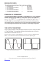 6
6
-
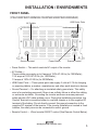 7
7
-
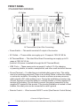 8
8
-
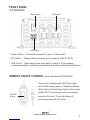 9
9
-
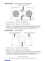 10
10
-
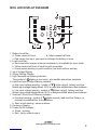 11
11
-
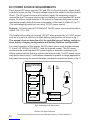 12
12
-
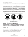 13
13
-
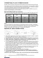 14
14
-
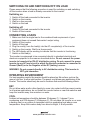 15
15
-
 16
16
-
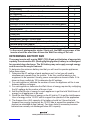 17
17
-
 18
18
-
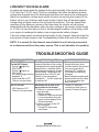 19
19
-
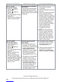 20
20
-
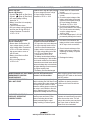 21
21
-
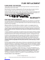 22
22
-
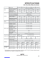 23
23
-
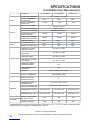 24
24
-
 25
25
-
 26
26
-
 27
27
-
 28
28
-
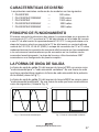 29
29
-
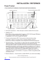 30
30
-
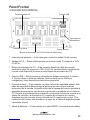 31
31
-
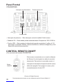 32
32
-
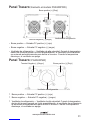 33
33
-
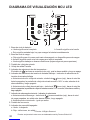 34
34
-
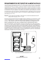 35
35
-
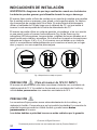 36
36
-
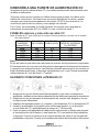 37
37
-
 38
38
-
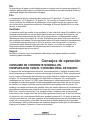 39
39
-
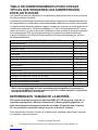 40
40
-
 41
41
-
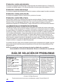 42
42
-
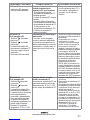 43
43
-
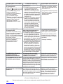 44
44
-
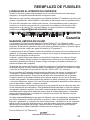 45
45
-
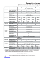 46
46
-
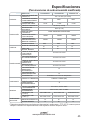 47
47
-
 48
48


Pooxtra PXA3000MSW Manual de usuario
- Categoría
- Adaptadores de corriente
- Tipo
- Manual de usuario
en otros idiomas
- English: Pooxtra PXA3000MSW User manual
Otros documentos
-
Stanley PI500S Manual de usuario
-
DeWalt DXAEPI1000 Manual de usuario
-
Vector MAXX SST VEC049D Manual de usuario
-
CAT CPI1000 Manual de usuario
-
Stanley PC509 Manual de usuario
-
Wagan SlimLine AC Inverter 2000 Watt Manual de usuario
-
Black & Decker Marine Battery Manual de usuario
-
-
-
Xantrex 1000I Manual de usuario