Vector MAXX SST VEC049D Manual de usuario
- Categoría
- Adaptadores de corriente
- Tipo
- Manual de usuario
Este manual también es adecuado para

MAXX SST
TM
COMPACT POWER INVERTER
INSTRUCTION MANUAL
Catalog Number VEC049D
Cat. # VEC049D Form # 90550749
June 2009 Copyright © 2009 Black & Decker Printed in China
VEA EL ESPAÑOL EN LA CONTRAPORTADA.
INSTRUCTIVO DE OPERACIÓN, CENTROS DE SERVICIO Y PÓLIZA DE GARANTÍA.
ADVERTENCIA: LÉASE ESTE INSTRUCTIVO ANTES DE USAR EL PRODUCTO.
Thank you for choosing Black & Decker!
Go to www.BlackandDecker.com/NewOwner
to register your new product.
PLEASE READ BEFORE RETURNING THIS
PRODUCT FOR ANY REASON:
If you have a question or experience a problem with your Black & Decker purchase, go to
HTTP://WWW.BLACKANDDECKER.COM/INSTANTANSWERS
If you can’t find the answer or do not have access to the internet,
call 1-800-544-6986 from 8 a.m. to 5 p.m. EST Mon. -- Fri. to speak with an agent.
Please have the catalog number available when you call.
for instant answers 24 hours a day.
SAVE THIS INSTRUCTION MANUAL FOR FUTURE REFERENCE.
90550749 VEC049D REVISED.qxp 6/5/09 1:11 PM Page i

1
SAFETY GUIDELINES / DEFINITIONS
DANGER: Indicates an imminently hazardous situation which, if not avoided, will result in death or serious injury.
WARNING: Indicates a potentially hazardous situation which, if not avoided, could result in death or serious injury.
CAUTION: Indicates a potentially hazardous situation which, if not avoided, may result in minor or moderate injury.
CAUTION: Used without the safety alert symbol indicates potentially hazardous situation which, if not avoided,
may result in property damage.
RISK OF UNSAFE OPERATION. When using tools or equipment, basic safety precautions should always be
followed to reduce the risk of personal injury. Improper operation, maintenance or modification of tools or
equipment could result in serious injury and property damage. There are certain applications for which tools
and equipment are designed. Black & Decker strongly recommends that this product NOT be modified and/or
used for any application other than for which it was designed. Read and understand all warnings and operating
instructions before using any tool or equipment.
GENERAL SAFETY WARNINGS AND INSTRUCTIONS
READ ALL INSTRUCTIONS
WARNING: Read all instructions before operating product. Failure to follow all instructions listed below may
result in electric shock, fire and/or serious injury.
• AVOID DANGEROUS ENVIRONMENTS Don’t use inverter in damp or wet locations. Don’t use inverter in the rain.
• KEEP CHILDREN AWAY. All visitors should be kept at a distance from work area.
• STORE IDLE INVERTERS INDOORS. When not in use, inverter should be stored indoors in dry, and high or
locked-up place – out of reach of children.
• DON’T FORCE APPLIANCE. It will do the job better and with less likelihood of a risk of injury at the rating for
which it was designed. Don’t overload inverter.
• USE SAFETY GLASSES AND OTHER SAFETY EQUIPMENT. Use safety goggles or safety glasses with side
shields, complying with applicable safety standards and, when needed, a face shield. Also use face or dust mask
if operation is dusty. This applies to all persons in the work area. Also use a hard hat, hearing protection, gloves,
safety shoes and dust collection systems when specified or required. Safety glasses or the like are available at
extra cost at your local dealer or Black & Decker Service Center.
• DON’T ABUSE CABLE. Never carry inverter by cable or yank it to disconnect from receptacle. Keep cable from
heat, oil, and sharp edges.
• DON’T OVERREACH. Keep proper footing and balance at all times.
• DISCONNECT APPLIANCES. Disconnect the appliance from the inverter when not in use.
• AVOID UNINTENTIONAL STARTING. Turn inverter off when not in use.
• PROPER COOLING is essential when operating the inverter. Do not place the unit near the vehicle’s heat vent
or in direct sunlight. Do not restrict air flow around inverter.
• USE OF ACCESSORIES AND ATTACHMENTS. The use of any accessory or attachment not recommended for use
with this inverter could be hazardous. Note: Refer to the accessory section of this manual for further details.
• STAY ALERT. Watch what you are doing. Use common sense.
• CHECK FOR DAMAGED PARTS. Ensure all cables, insulation and connectors are in good operating condition.
• DO NOT OPERATE inverter and appliances near flammable liquids or in gaseous or explosive atmospheres.
Motors in these tools normally spark, and the sparks might ignite fumes.
• EXTENSION CORDS. Make sure your extension cord is in good condition. When using an extension cord, be
sure to use one heavy enough to carry the current your product will draw. An undersized cord will cause a
drop in line voltage resulting in loss of power and overheating. The accompanying table shows the correct
size to use depending on cord length and nameplate ampere rating. If in doubt, use the next heavier gauge.
The smaller the gauge number, the heavier the cord.
Minimum Gauge for Cord Sets
Volts Total Length of Cord in Feet
120V 0-25 26-50 51-100 101-150
(0-7,6m) (7,6-15,2m) (15,2-30,4m) (30,4-45,7m)
240V 0-50 51-100 101-200 201-300
(0-15,2m) (15,2-30,4m) (30,4-60,9m) (60,9-91,4m)
Ampere Rating
More Not more American Wire Gauge
Than Than
0 - 6 18 16 16 14
6 -101816 14 12
10 -121616 14 12
12 - 16 14 12 Not Recommended
90550749 VEC049D REVISED.qxp 6/5/09 1:11 PM Page 1

IMPORTANT SAFETY INSTRUCTIONS
WARNING: This product or its power cord contains lead, a chemical known to the State of California to cause
cancer and birth defect or other reproductive harm. Wash hands after handling.
WARNING: TO REDUCE THE RISK OF ELECTRIC SHOCK:
• Do not connect to AC distribution wiring.
• Do not make any electrical connections or disconnections in areas designated as IGNITION PROTECTED. This
unit is NOT approved for ignition protected areas.
• NEVER immerse the unit in water or any other liquid, or use when wet.
• Do not insert foreign objects into the AC outlet or the USB outlet (if provided).
WARNING: TO REDUCE THE RISK OF FIRE:
• Do not operate near flammable materials, fumes or gases.
• DO NOT expose to extreme heat or flames.
CAUTION: TO REDUCE THE RISK OF INJURY OR PROPERTY DAMAGE:
• Remove appliance plug from outlet before working on the appliance.
• DO NOT attempt to connect or set up the unit or its components while operating your vehicle. Not paying
attention to the road may result in a serious accident.
• ALWAYS use the inverter where there is adequate ventilation. Do not block ventilation slots.
• ALWAYS turn the inverter OFF by disconnecting it from the power source when not in use.
• Make sure the nominal powering voltage is 12 volts DC.
• When using this unit in a vehicle, check the vehicle owner’s manual for maximum power rating and
recommended output. Do not permanently install in engine compartment — install in a well ventilated area.
• Do not use with positive ground electrical systems*. Reverse polarity connection will result in a blown fuse and
may cause permanent damage to the inverter and will void warranty.
*The majority of modern automobiles, RVs and trucks are negative ground.
• Keep in mind that this inverter may not operate very high wattage appliances or equipment that produce heat.
Refer to “Appliance Consumption” chart in this manual.
• Do not open the inverter — there are no user-serviceable parts inside.
• Do not use this inverter with medical devices. It is not qualified for medical applications.
• Keep away from children. This is not a toy!
• Install and operate unit only as described in this Instruction Manual.
• Do not use this inverter on a watercraft. It is not qualified for marine applications.
• Check unit periodically for wear and tear. Take to a qualified technician for replacement of worn or defective
parts immediately.
IMPORTANT CABLE INFORMATION:
Substantial power loss and reduced battery operating time results from inverters installed with cables that are
not able to supply full power. Symptoms of low battery power can result from cables that are either excessively
long or an insufficient gauge. The installer/operator should be especially aware of the requirements to maintain
secure, tight, electrical connections and provide strain relief for DC cables and appliance wiring. Cable
insulation must be the appropriate type for the environment.
WARNING: TO REDUCE THE RISK OF FIRE:
• Do not operate near flammable materials, fumes or gases.
• DO NOT expose to extreme heat or flames.
• Ensure all cables and connections are tightly secured.
CAUTION: TO AVOID DAMAGE TO THIS INVERTER OR EQUIPMENT YOU INTEND TO USE WITH THIS
INVERTER: For Temporary Installation, only use the Black & Decker/Vector Cable Set identified in the
“Installation” and “Specifications” sections of this Instruction Manual. Permanent Installation must be
performed by a professional as specified in the “Installation” section of this Instruction Manual.
• Read And Understand This Instruction Manual Before Using This Unit.
SAVE THESE INSTRUCTIONS
2
90550749 VEC049D REVISED.qxp 6/5/09 1:11 PM Page 2

3
THIS MANUAL CONTAINS IMPORTANT SAFETY AND OPERATING INSTRUCTIONS FOR THE MAXX SST
TM
COMPACT POWER INVERTER MODEL VEC049D.
WARNING: TO REDUCE THE RISK OF INJURY:
• Follow these instructions and those published by battery manufacturer and the manufacturer of any
equipment you intend to use with this unit. Review cautionary markings on these products and on engine.
INTRODUCTION
Thank you for purchasing the
VEC049D MAXX SST
TM
Compact Power Inverter.
Please read this Instruction
Manual carefully before use to ensure optimum performance and to avoid damage to this product.
This Power Inverter is configured with the latest Soft Start Technology (SST) and supplies continuous power
and peak watts in the form of 120 volt AC outlets to run most household or electronic appliances. Before
introduction of SST, high start-up currents from large inductive loads could shut down an inverter. SST
improves inverter operation by:
• Gradual voltage ramp-up during inverter start-up, eliminating failed cold starts under load.
• Output that momentarily dips in voltage and quickly recovers to allow large motorized loads to start, eliminating
most shutdowns from momentary overloads.
• Soft Start Technology, dramatically increases reliability and life of the product.
Added features include automatic shutdown and a low battery alarm to prevent damage to your battery.
FEATURES
On the front panel are two LED indicators. The green LED indicates power and proper operation of the inverter;
the red LED indicates inverter shutdown from over-load or over-temperature condition, or abnormal input
voltages. The ON/OFF Switch turns the inverter ON and OFF. The switch can also be used to force reset of
inverter circuits by switching it OFF, then back ON again. All models also feature a port to attach a remote
control (sold separately).
120 volt AC power is supplied through two North American three-prong type outlets. The outlets can
accommodate either two- or three-pin AC plugs.
Controls and Functions
Maxx SST™ Automatic Features
Built-in Automatic Features include:
• Overload and over-temperature shutdown activated if AC output exceeds rated watts
• AC short-circuit shutdown
• Low voltage audible alarm (sounds at 10.5 volts input)
• Low-voltage shutdown (activates at 10.0 volts DC)
• High-input voltage shutdown (activates at above 15.5 volts DC)
MAXX SST™ uses a 12 volt DC power source like those found in motor vehicles, or it can be operated using
multiple battery configurations with commercial battery chargers or solar battery chargers. For most heavy-duty
applications, a multiple battery configuration and the use of deep-cycle batteries is required.
PORT FOR
REMOTE CONTROL
(SOLD SEPARATELY)
GREEN POWER LED
INDICATOR
Front View Diagram Back View Diagram
WATTAGE POWER
METER
ON/OFF
POWER
SWITCH
(2) 120 VOLT AC
OUTLETS
RED FAULT
LED INDICATOR
HIGH-SPEED
COOLING FAN
NEGATIVE (–)
TERMINAL
GROUNDING
TERMINAL
POSITIVE (+)
TERMINAL
90550749 VEC049D REVISED.qxp 6/5/09 1:11 PM Page 3

When using multiple batteries, inverters can be operated from one of the vehicle 12 volt batteries, so there’s
always one battery with adequate charge to start an engine.
MAXX SST™ includes a high-surge capability. This is required to start heavy loads, such as motors and other
inductive devices.
The inverter contains automated features that will reset and re-start its operation after overload and thermal
shutdown without action by the user.
WARNING: To reduce the risk of injury or property damage: If the appliance does not work or stops
working, unexpectly, or even momentarily, turn off the appliance and disconnect from inverter until the cause is
identified and corrected.
PRINCIPLE OF OPERATION
The MAXX SST™ inverter converts 12 volt DC (direct current) from a vehicle battery or other 12 volt DC power
source to standard 120 volt AC (alternating current) household power.
The Power Inverter Output Waveform
The AC output waveform of the Power Inverter is known as “modified sine wave.” It is a waveform that has
characteristics similar to the sine wave shape of utility power. This type of waveform is suitable for most AC
loads, including linear and switching power supplies used in electronic equipment, transformers, and motors.
The modified sine wave produced by the Power Inverter has an RMS (root mean square) voltage of 120 volts,
which is the same as standard household power. Most AC voltmeters (both digital and analog) are sensitive to
the average value of the waveform rather than the RMS value. They are calibrated for RMS voltage under the
assumption that the waveform measured will be a pure sine wave. These meters will not read the RMS voltage
of a modified sine wave correctly. They will read about 20 to 30 volts low when measuring the output of the
inverter. For accurate measurement of the output voltage of this unit, use a true RMS reading voltmeter such as
a Fluke 179, Fluke 79 III series, Beckman 4410 or Triplett 4200.
Modified Sine Wave and Sine Wave Comparison
Incompatible Products:
CAUTION: Certain products contain power supplies or circuits that are not compatible with an
inverter using a modified sine wave output (such as this inverter) and may be damaged by using this
inverter.
If your product requires pure sine wave AC input power to function properly, the instruction manual
for your product could state this. If in doubt, you should contact your product manufacturer PRIOR
TO USE.
Some products must be powered from a pure sine wave power source, such as standard household
power, or a "pure sine wave" inverter in order to function properly.
Your product could be damaged by this inverter if it contains:
1. Transformer type power supplies
2. Microprocessor controlled power supplies
3. Capacitive coupled power supplies
If an incompatible product is used with this inverter:
•
The product might not operate at all, with no indication of failure. The product fuse might have
opened as a result of trying to use it with the inverter.
•
The product exhibits unusual operation (such as, intermittent operation, buzzing, and the like.)
WARNING:
If the product does not operate normally, to reduce the risk of injury or property damage:
•
Turn the product off immediately and unplug it from the inverter.
APPLIANCE POWER CONSUMPTION
MAXX SST™ inverters are ideal for powering:
• Lights
• TVs and TV/DVD (VCR) combinations units
• Radio receivers/transceivers and stereo systems
• Computers and peripheral equipment
4
90550749 VEC049D REVISED.qxp 6/5/09 1:11 PM Page 4

• Refrigerator/freezers
• Small microwave ovens
• Household appliances
• Dry and/or wet/dry vacuums
• Heavy duty power tools & chargers
• Sump pumps, motors and other electric-powered equipment
Most electrical tools, appliances and audio/video equipment have labels that show the unit’s power consumption in
amps, watts, or both. To avoid inverter shutdown and possible damage to the inverter, avoid exceeding the wattage
rating of this unit. To obtain a rough estimate of the current (in amperes) the power source must deliver where
the power consumption of the tool or device is given in watts AC, simply divide the power consumption of the
load by 10. Example: If a load is rated at 200 watts AC, the power source must be able to deliver: 200 divided
by 10 = 20 amperes.
The inverter has built-in overload protection so that if you do exceed the inverter’s output capacity continuously,
the unit will automatically shut down. Once the excessive load is removed, the inverter can be restarted and
resume normal operation.
Note:
To restart the inverter, turn it off, and then on again. The on/off Switch is located on the unit’s
Front Panel (refer to the “Control and Functions” section of this Instruction Manual).
The inverter powers resistive loads the easiest; however, larger resistive loads, such as electric stoves or
heaters, could draw more wattage than the inverter can deliver on a continuous basis.
CAUTION: TO REDUCE THE RISK OF PROPERTY DAMAGE:
Ensure that total continuous power consumption of all tools and/or appliances connected to the inverter (and in
use) does not exceed the inverter’s continuous watts rating. Also ensure that start-up wattage for inductive
loads does not exceed peak watts for more than a second.
Appliances such as microwave ovens will normally draw more than their rated current and could possibly
overload the inverter when operating simultaneously with other appliances. For example: A 600 watt
microwave oven draws approximately 940 watts.
The following chart shows the approximate amperage and corresponding wattage at 120 volts AC for various
common tools and appliances.
APPLIANCE CONSUMPTION IN AMPS AND WATTS CHART
APPLIANCE AMPS@ WATTS@
120VAC 120VAC
Laptop Computer 0.45 55
Household Power Mixer 1.83 220
240-Watt Stereo/Amplifier 2.01 242
Refrigerator 2.75 330
3/8" Variable Speed Drill 2.75 330
Variable Speed Jig Saw 2.75 330
10-Speed Blender 2.93 352
Belt Sander 3.11 374
3/8" Reversible Drill 3.20 385
Household Food Processor 3.30 396
Computer and Monitor 3.66 440
Portable Vacuum 4.21 506
8-Cup Coffee Maker 5.04 605
Electric Trimmer 5.04 605
1/2" Hammer-Drill 5.04 605
Reciprocating Saw 5.50 660
Vacuum Cleaner 6.60 792
1-1/8" Rotary Hammer 7.15 858
1/6 H.P. Submersible Sump Pump 7.33 880
Compact Microwave Oven 7.91 935
10" Bench Saw 12.50 1500
5
90550749 VEC049D REVISED.qxp 6/5/09 1:11 PM Page 5

Note: Appliance specifications may vary from brand to brand. This table is offered only as a guide to
approximate power ratings. Check appliance manuals or product labeling for actual ratings.
For continuous use at maximum output, the MAXX SST™ inverter must be connected to a DC
power supply capable of providing at least 1/10th of the inverter’s continuous wattage rating.
The inverter will operate most AC loads within its power rating. Some induction motors used in refrigerators,
freezers, pumps and other motor-operated equipment, require very high surge currents to start them. The
inverter may not be able to start some of these motors even though their rated current draw is within
specifications for this power inverter.
If a motor refuses to start, observe the battery voltage using a DC voltmeter while trying to start the motor. If
the battery voltmeter drops below 11 volts while the inverter is attempting to start the motor, this may be why
the motor won’t start. Make sure the battery connections are tight and the battery (or batteries) is (are) fully-
charged. If the connections are good and the battery is charged, but the voltage still drops below 11 volts, you
may need to use a larger battery (or battery combination).
OPERATING INSTRUCTIONS
Power Source Requirements
The inverter will operate from input voltages between 11 and 15 volts DC. If the voltage drops below 10.5 volts,
an audible low battery warning alarm will sound. The inverter will shut down if the input voltage drops below 10
volts DC. This built-in feature protects the battery from being completely discharged.
The inverter will also shut down if the input voltage exceeds 15.5 volts. This
protects the inverter against excessive input voltage. Although the inverter has built-in protection against over
voltage, it may still be damaged if the input voltage exceeds 15.5 volts.
Inductive loads, such as TVs and stereos, require more current to operate than do resistive loads with the same
wattage rating. Induction motors, as well as some TVs, may require two to six times their rated wattage to start
up. Because the MAXX SST™ inverters have a peak watt power rating, many such appliances and tools may be
safely operated. The equipment that needs the highest starting wattage are pumps and compressors that start
under load. This equipment can be safely tested. If an overload is detected, the inverters will simply shut down
until the overload situation is corrected. Use the front panel switch to turn OFF the inverter, then ON, to reset
the inverter.
CAUTION: TO REDUCE THE RISK OF PROPERTY DAMAGE:
• Exceeding recommended voltage limits will void manufacturer’s warranty.
• NEVER try to use the inverter with any 12 volt DC power source that uses a positive ground.
(Most vehicles use negative ground systems.)
Determining Battery Size
To determine the minimum battery size you will need to operate appliances from MAXX SST™ inverters, follow
these steps:
1. Determine the wattage of each appliance and/or tool you will need to
simultaneously operate from the inverter. To do this, read the labels on the equipment to be operated.
2. Estimate the number of hours the equipment will be in use between battery recharges.
3. Determine the total watt-hours of energy use, the total running time and the average power consumption.
Keep in mind that some appliances are not drawing the same power continuously. For example, a typical home-
use coffee maker draws 500 watts during brew time (approx. 5 minutes), but maintains the pot temperature at
only about 100 watts. Typical use of a microwave is only for a few minutes, sometimes at low power.
Runtime
The following graph is a set of curves that show how appliance load, in watts or in amperes, affects runtime.
These curves are only estimates of operating time, dependent upon:
• The condition of the batteries
• The state of charge on the batteries
• The amount of other DC appliances drawing current from the batteries
Three curves were developed for a battery of 50 Ampere Hours (AH) capacity, and three for multiple batteries in
parallel. The higher capacity curves are for 120 AH, 200 aH and 400 aH capacities. These large capacity
batteries clearly extend operating time at full load. To extend operating time in general, reduce the heavy
appliance load to a minimum. Remember, you are operating on stored energy and probably under power loss
conditions.
Note: All operating time curves assume permanent installation with the appropriate DC input wire
(See the “Specifications” section of this Instruction Manual) and a full charge on the batteries.
6
90550749 VEC049D REVISED.qxp 6/5/09 1:11 PM Page 6

For example, as shown in the above graph, using a 400 A/h battery (batteries), if the average power usage will
be 1000 watts, the operating time will be about 150 minutes. A larger capacity battery will deliver more
operating time between recharges.
Note: The manufacturer recommends conservative estimates when selecting a battery. More amp
hours will deliver a reserve capacity, and a larger capacity battery will not be subject to deep
discharges. Ideally, the number of amp hours (A/h) you expect to use should be less than
50% of the battery’s rated capacity.
Protective Features
LOW BATTERY ALARM
An audible alarm will sound when the 12 volt DC power supply voltage drops down to 10.5 ± 0.3 volts. This
indicates that the battery needs to be charged or there is an excessive voltage drop between the battery power
source and the inverter.
Notes: It is normal for the alarm to sound when the inverter is being connected to, or disconnected
from, a 12 volt DC power source. This does not indicate a problem. However, if this alarm
sounds continuously, discontinue inverter operation and charge the battery before resuming
operation. If the voltage drops to 10.0 volts DC, the inverter will automatically shut down. If
the low voltage alarm sounds when the battery is fully charged refer to the
“Troubleshooting” section of this Instruction Manual).
CIRCUIT PROTECTION
The inverter has electronic circuit protection against overload or short circuit conditions.
WARNING: TO REDUCE THE RISK OF INJURY OR PROPERTY DAMAGE:
If turning the ON/OFF Switch OFF then ON again does not reset the inverter, DO NOT ATTEMPT TO OPEN THE
INVERTER. Opening the inverter for any reason will void the warranty. The unit must be returned to Vector
Manufacturing for testing and repair by professional factory technicians.
INSTALLATION
MAXX SST™ inverters will provide you with continuous electrical power when powered by a 12 volt DC source,
such as a vehicle battery or a multiple battery configuration (Permanent Battery Configuration Diagram). This
manual does not describe all of the possible configurations.
For optimum operation, the inverter should be placed or mounted on a flat surface; ideally, a normally cool
metal surface to help diffuse the heat that is generated. The cables for Permanent Installation (see the
“Permanent Battery Configuration Diagram”) are not supplied, but will be required to allow for full power
operation and to provide flexibility in positioning the inverter.
Watts
Power Level
Amps
100 10
200 20
300 30
400 40
500 50
600 60
700 70
800 80
900 90
1000 100
50 A/h
120 A/h
200 A/h
400 A/h
OPERATING TIME CHART FOR LOAD AND BATTERY CAPACITY AVAILABLE
Minutes 15 30 45 80 75 90 105 120 135 150 165 180 195 210 235 240
Battery Operating Times
7
90550749 VEC049D REVISED.qxp 6/5/09 1:11 PM Page 7

Operating Environment
Do not locate inverters in an area, room or compartment where explosives or flammable fumes might be
present, such as engine rooms, engine compartments, and boats or small, unvented battery compartments.
To avoid possible dangerous conditions, the inverters must be located where:
1. The unit is kept dry;
2. Air temperature is between 30°F (–1°C), non-condensing, and 105° F (40°C);
3. At least three inches of clearance from other objects is maintained for cooling airflow;
4. The unit is not exposed to direct heat, sunlight or to explosive or flammable fumes; and
5. The unit is as close to the DC power source as possible.
Never connect the chassis ground wire from the inverter to the DC negative input.
• CHECK to ensure that the combined loads of the appliances being powered by the inverter DO NOT continuously
exceed the inverter’s wattage rating.
• NEVER place items on or over the inverter during operation.
MAXX SST™ inverters generate heat during operation and must be placed where cool air can circulate to the
internal fan, and hot air can be removed.
Installation Procedures
When wiring the inverter to a 12 volt DC power source, ensure that polarity is correct. Reversed polarity will
blow a fuse and may cause permanent damage to the inverter. Review “Back View” diagrams on page 3, if
necessary, to identify the location of the DC terminals.
Note: The manufacturer’s warranty does NOT cover damage due to reversed polarity.
Temporary Installation
For Temporary Installation, only use the provided 3 feet long cables each using #2AWG wire terminated with a
ring terminal attached at the battery (power source) end and a Special Crimp Connector attached at the inverter
end. The Special Crimp Connectors are designed for proper connection to the 12 volt input power terminals on
the inverter; connection using any other method is not acceptable.
1. Check to be sure the inverter’s ON/OFF Power Switch is in the OFF position and that no flammable fumes are
present.
2. Locate the Positive (+, POS) and Negative (-, NEG) terminals on the 12 Volt DC battery (or other 12VDC
power source).
3. Locate the Positive (Red, +) and Negative (Black, -) DC input terminal on the inverter.
4. Connect the Special Crimp Connectors of the Positive (Red, +) cable to the Positive (Red, +) terminal
on the
inverter and tighten the set screws against the flat side of the connectors.
5. Connect the ring terminal of the Positive (Red, +) cable to the Positive (Red, +) terminal on the 12 Volt DC
battery (or other 12VDC power source).
6. Connect the Special Crimp Connector of the Negative (Black, -) cable to the Negative (Black, -) terminal on
the inverter and tighten the set screws against the flat side of the connector.
7. Connect the ring terminal of the Negative (Black, -) cable to the Negative (-, NEG) terminal on the 12 Volt DC
battery (or other 12VDC power source). There may be some minor sparking when the cable is touched to the
battery terminal.
WARNING: If persistent, severe arcing occurs between the cable and battery terminals, immediately cease
attempting to make the connection and correct the cause of the problem before continuing.
8. Ensure that all of the electrical connections have been tightened.
9. Set the inverter’s ON/OFF Power Switch to the ON position and verify the Green Power LED Indicator
illuminates and the Red Fault LED Indicator does not illuminate.
10.As a test, plug in a lamp with a 60 or 100 Watt light bulb into one of the inverter’s 120 Volt AC Outlets and
switch the lamp ON. If the lamp lights normally, the inverter is functioning properly and use of the inverter
with other appliances can continue. If the lamp does not light, or does not operate normally:
A. Refer to the “Fault Protection and Troubleshooting Guide” of this Instruction Manual for suggested solutions.
B. If conducting step A does not find and correct the problem, refer to the “Service Information” section of this
Instruction Manual for assistance.
8
90550749 VEC049D REVISED.qxp 6/5/09 1:11 PM Page 8

Permanent Installation
The permanent installation of the inverter and the required wiring and safety devices to the 12 Volt DC power
source must be performed by a professional installer. Further requirements are:
1. The inverter is supplied with 2 Special Crimp Connectors to connect the power source wiring to the inverter
DC input terminals. They are designed to be crimped onto #2AWG copper conductor cables (not supplied).
2. The #2AWG power source cables must not exceed 6 feet in length.
3. A 200 Amp ANL Fuse (not supplied) installed in the proper Fuse Holder (not supplied) must be connected in-
line as part of the positive power source input cable as close as possible to the power source connections.
4. A #12AWG insulated wire should be connected between the Grounding Terminal on the inverter (see
“Controls and Functions”, “Back View Diagram” on page 4 ) and the ground terminal on the appliance (such
as a TV or Radio) to minimize electrical noise and reception interference.
CAUTION: Do not connect this wire to the inverter’s Negative (Black, -) DC input terminals.
CAUTION: Violation of these requirements may result in unsafe operation and/or equipment failure. Damage
to the inverter as a result of improper installation voids the warranty.
The DC power source must be a well-regulated DC power supply as typically found in vehicle and deep-cycle
marine batteries. The DC power source may also be two 12 volt batteries connected in parallel. On larger
applications the power source may be several batteries connected in parallel as shown in the following
“Permanent Battery Configuration” diagram.
Note: For typical heavy-duty uses in a Permanent Installation, an ANL fuse must be added as close
as possible to the power source (battery) positive terminal. The fuse amperage size must be
appropriate to allow simultaneous operation of all the AC appliances to be powered, with
delay characteristics that allow for the momentary high start-up current requirements of
inductive loads. Use the specified fuse block (fuse holder) and fuse. For full rated output and
motor start-up surge output, ensure that the installation is configured to handle the full load.
See the “Permanent Installation” section of this Instruction Manual.
Connection To Load
The Power Inverter is equipped with standard North American three-prong type outlets. Plug the cord from the
equipment you wish to operate into the AC outlet(s). Make sure the combined load requirement of your
equipment does not exceed maximum continuous power.
The Power Inverter is engineered to be connected directly to standard electrical and electronic equipment in the
manner described above. Do not connect the Power Inverter to household or RV AC distribution wiring. Do not
connect the Power Inverter to any AC load circuit in which the neutral conductor is connected to ground (earth)
or to the negative of the DC (battery) source.
WARNING: TO REDUCE THE RISK OF ELECTRIC SHOCK, PROPERTY DAMAGE OR PERSONAL INJURY:
Never connect unit directly to AC distribution wiring.
Operating Tips
For best operating results, the inverter should be placed on a stable, flat surface. The inverter should only be
used in locations that meet the following criteria:
DRY — Do not allow water or other liquids to come into contact with the inverter.
BATTERY CHARGING
FROM COMMERCIAL
AC, ENGINE, SOLAR, ETC.
BATTERY
BATTERY
BATTERY
BATTERY
(MAX FEET OF
AWG WIRE)
(See the “Specifications” section)
ANL FUSE
FUSE HOLDER
(MAX FEET OF
AWG WIRE)
(See the “Specifications” section)
FUSE TO BATTERY LENGTH
+ FUSE TO INVERTER LENGTH
MAXX SST™
POWER
INVERTER
Permanent Battery
Configuration Diagram
9
90550749 VEC049D REVISED.qxp 6/5/09 1:11 PM Page 9

COOL — Surrounding air temperature should be between –0°C and 40°C — ideally between 15°C and 25°C
(60-80°F). Keep the inverter away from direct sunlight, when possible.
WELL-VENTILATED — Keep the area surrounding the inverter clear to ensure free air circulation around the
unit. Do not place items on or over the inverter during operation. The unit will shut down if the internal
temperature gets too hot.
SAFE — Do not use the inverter near flammable materials or in any locations that may accumulate flammable
fumes or gases. This is an electrical appliance that can briefly spark when electrical connections are made or
broken.
Notes on Using the Remote Control (sold separately)
For ease of use, Vector offers (as a separate item) a Remote Control specifically designed for this line of MAXX
SST inverters. The inverter ON/OFF Switch must be in the OFF position when connecting the Remote Control to
the unit or the Remote Control will not operate. Once the unit has been turned ON using the Remote Control,
inverter operation will continue to be controlled through the Remote Control. Turn the inverter OFF before
disconnecting the Remote Control.
For more information about attaching and using the Remote Control, please refer to the Remote Control User’s
Manual.
TROUBLESHOOTING
Common Audio/Visual Problems
Problem Solution
“Buzzing” sound in audio
systems
Some inexpensive stereo systems and “boom boxes” emit a buzzing sound from
their speakers when operated from the Power Inverter. This occurs because the
power supply in the electronic device does not adequately filter the modified sine
wave produced by the inverter. The only solution to this problem is to use a higher
quality sound system that incorporates a higher quality power amplified supply.
Television Interference The Inverter is shielded to minimize interference with TV signals. However, in
some instances, some interference may still be visible, particularly with weak TV
signals. Try the following corrective measures:
• Position the inverter as far as possible from the television, the antenna and the
antenna cables. Use an extension cable, if necessary.
• Adjust the orientation of the inverter, the antenna cables and the TV power cord
to minimize interference.
• Make sure the antenna feeding the television provides an adequate (“snow
free”) signal and that high quality, shielded antenna cable is used.
• Do not use the inverter to operate high-power appliances or tools at the same
time you are using it to operate the TV.
• Make sure the inverter’s case is properly grounded (refer to the “Permanent
Installation Procedure” section of this Instruction Manual).
10
90550749 VEC049D REVISED.qxp 6/5/09 1:11 PM Page 10

11
Fault Protection and Troubleshooting Guide
INVERTER POWER SWITCH TURNED ON
Resetting the Unit
When a thermal shutdown problem occurs, the inverter will reset and turn back on automatically after it cools.
WARNING: To reduce the risk of injury or property damage: If the appliance stops working, even
momentarily, turn off the appliance and disconnect from the inverter until the cause is identified and corrected.
CARE AND MAINTENANCE
Storage
1. Ideal storage temperature range is 50-68°F (10-20°C).
2. Store and use the inverter in a cool, dry place with adequate ventilation.
3. Avoid locations that are exposed to heating units, radiators, direct sunlight or excessive humidity or dampness.
Fuse Replacement
This inverter is equipped with multiple internal fuses. Normally, these fuses will not “blow” unless there is a
serious problem inside the unit.
Internal fuses are replaceable; however, only trained personnel should
attempt fuse replacement.
Refer to the “Service Information” section of this Instruction Manual.
Preventive Maintenance
Inverters require minimal maintenance. For optimum performance, the manufacturer recommends periodically
performing the following preventive maintenance.
1. Turn OFF the inverter using the front panel ON/OFF Power Switch.
2. Remove the DC power fuse.
3. Check and tighten all electrical connections, including the ground.
4. Using a non-metallic vacuum cleaner hose, vacuum the air slots and fan area.
5. Clean the outside of the unit using a damp (not wet) cloth.
6. Wipe unit surfaces thoroughly with a dry cloth.
7. Re-insert the fuse and resume operation.
Accessories
Recommended accessories for use with your tool are available from your local dealer or authorized service center.
If you need assistance regarding accessories, please call: 1-800-544-6986.
WARNING: The use of any accessory not recommended for use with this tool could be hazardous.
Trouble/Indication Possible Cause Suggested Remedy
No AC output — DC input is below 10 volts Recharge or replace battery.
red LED lit
Excessive appliance load Turn unit OFF. Reduce the load, wait for the
— thermal shutdown inverter to cool down, then turn the unit ON
again.
No AC output — Fuse(s) open Check DC input — fuse(s) in vehicle. Replace
green LED not lit the fuse with one of the same type and
rating if necessary.
Low battery alarm Low battery voltage Recharge battery. Remove load from the
sounds continuously inverter while recharging battery.
Bad connection or wiring Tighten all DC connections.
Motorized power tool Excessive start-up load If appliance does not start, appliance is
will not start drawing excessive current and will not work
with inverter.
Motorized power tool Purely inductive load Make the load not purely inductive. Operate
does not operate at an incandescent lamp at the same time as
correct speed motor.
Television/radio Snow in picture, Keep inverter and antenna distant from each
interference “buzzing” sound other. Use shielded antenna. Connect antenna
to amplifier.
90550749 VEC049D REVISED.qxp 6/5/09 1:11 PM Page 11

12
SPECIFICATIONS
Maximum continuous power: 1000 watts
Surge capacity (peak power): 2000 watts
Output voltage range: 105-125 volts
Output frequency: 58-62 Hz
Output voltage: 120 VAC
Maximum efficiency: >_ 87%
Full load efficiency: >_ 82%
No load current draw: >0.5 amp
Over voltage shutdown: 15.5 ± 0.5 volts DC
Low voltage shutdown: 10.0 ± 0.3 volts DC
Thermal shutdown auto reset: Yes
North American standard outlets: 2
ANL fuse rating for direct hardwire: 200
Proper cable gauge (AWG) @ 6 ft. #2X2
90550749 VEC049D REVISED.qxp 6/5/09 1:11 PM Page 12

13
2 YEAR LIMITED WARRANTY PROGRAM
This limited warranty program is the only one that applies to this product, and it sets forth all the responsibilities of
Vector Products, Inc., regarding this product. There is no other warranty, other than those described herein.
This Vector Products, Inc. product is warranted, to the original purchaser only, to be free of defects in materials and
workmanship for two years from the date of purchase without additional charge. The warranty does not extend to
subsequent purchasers or users. Vector Products, Inc. will not be responsible for any amount of damage in excess
of the retail purchase price of the product under any circumstances. Incidental and consequential damages are
specifically excluded from coverage under this warranty.
This product is not intended for commercial use. This warranty does not apply to accessories or damage to units from
misuse or incorrect installation. Misuse includes wiring or connecting to improper polarity power sources.
RETURN/REPAIR POLICY: Defective products, other than accessories, may be returned postage prepaid to
Vector Products, Inc.. Any defective product, other than accessories, that is returned to Vector Products, Inc. within
30 days of the date of purchase will be replaced free of charge. If such a product is returned more than 30 days
but less than two years from the purchase date, Vector Products, Inc. will repair the unit or, at its option, replace it
free of charge.
If the unit is repaired, new or reconditioned replacement parts may be used, at Vector Products, Inc.’s option.
A unit may be replaced with a new or reconditioned unit of the same or comparable design. The repaired or
replaced unit will then be warranted under the terms of the remainder of the warranty period. The customer is
responsible for the shipping charges on all returned items after 30 days. During the warranty period, Vector
Products, Inc. will be responsible for the return shipping charges.
LIMITATIONS: This warranty does not cover accessories, bulbs, fuses and batteries, defects resulting from normal
wear and tear (including chips, scratches, abrasions, discoloration or fading due to usage or exposure to sunlight),
accidents, damage during shipping to our service facility, alterations, unauthorized use or repair, neglect, misuse,
abuse, failure to follow instructions for care and maintenance, fire, flood and Acts of God.
If your problem is not covered by this warranty, call our Technical Support Department at Toll Free at
(800) 544-6986 for general repair information and charges if applicable.
STATE LAW RIGHTS: This warranty gives you specific legal rights. Some states do not allow limitations on how
long an implied warranty lasts or the exclusion or limitation of incidental or consequential damages, so the
exclusions or limitations stated herein may not apply. This warranty gives the purchaser specific legal rights; other rights,
which vary from state to state, may apply.
TO REQUEST WARRANTY SERVICE FOR THIS PRODUCT: Contact Technical Support by telephone, fax or
mail. We suggest that you keep the original packaging in case you need to ship the unit. When returning a product,
include your name, address, phone number, dated sales receipt (or copy) and a description of the reason for return
and product serial number. After repairing or replacing the unit, we will make every effort to return it to you within
four weeks.
WARRANTY ACTIVATION: Please complete Warranty Activation Card and mail to Vector Products, Inc.. Enter
“VEC049D” as Model and “MAXX SST
TM
1,000 WATT COMPACT POWER INVERTER
”
as Product Type. All Vector
Products, Inc. products must be registered within 30 days of purchase to activate this warranty. Mail the completed
registration form, along with a copy of the original sales receipt to:
IMPORTED BY:
VECTOR PRODUCTS, INC.
701 EAST JOPPA ROAD, TOWSON, MD 21286
• TOLL FREE: 1-800-544-6986 •
WARRANTY IS NON-TRANSFERABLE AND NON-REFUNDABLE.
90550749 VEC049D REVISED.qxp 6/5/09 1:11 PM Page 13

14
MANUAL DE INSTRUCCIONES DEL
CONVERSOR ELÉCTRICO COMPACTO
MAXX SST
TM
Número de catálogo VEC049D
LLEEAA EELL MMAANNUUAALL AANNTTEESS DDEE DDEEVVOOLLVVEERR
EESSTTEE PPRROODDUUCCTTOO PPOORR CCUUAALLQQUUIIEERR MMOOTTIIVVOO::
Si tiene una consulta o algún inconveniente con su producto Black & Decker, visite
HTTP://WWW.BLACKANDDECKER.COM/INSTANTANSWERS
Si no encuentra la respuesta o no tiene acceso a Internet, llame al 1-800-544-6986 de
lunes a viernes de 8 a.m. a 5 p.m. hora del Este para hablar con un agente.
Cuando llame, tenga a mano el número de catálogo.
para obtener respuestas instantáneas las 24 horas del día.
Gracias por elegir Black & Decker!
Visite www.BlackandDecker.com/NewOwner
para registrar su nuevo producto.
CONSERVE ESTE MANUAL PARA FUTURAS CONSULTAS.
90550749 VEC049D REVISED.qxp 6/5/09 1:11 PM Page 14

15
NORMAS DE SEGURIDAD/DEFINICIONES
PELIGRO: Indica una situación de peligro inminente que, si no se evita, provocará la muerte o lesiones graves.
ADVERTENCIA: Indica una situación de peligro potencial que, si no se evita, podría provocar la muerte o lesiones
graves.
ATENCIÓN: Indica una situación de peligro potencial que, si no se evita, puede provocar lesiones leves o
moderadas.
ATENCIÓN: Usado sin el símbolo de alerta de seguridad indica una situación de peligro potencial que, si no se evita,
puede provocar daños en la propiedad.
RIESGO DE OPERACIÓN INSEGURA. Cuando se usan herramientas o equipos, siempre se deben respetar las
precauciones de seguridad para reducir el riesgo de lesiones personales. La operación, la modificación o el
mantenimiento incorrectos de herramientas o equipos pueden provocar lesiones graves y daños a la propiedad. Las
herramientas y los equipos están diseñados para determinados usos. Black & Decker recomienda enfáticamente que
NO se modifique este producto y que NO se utilice para ningún otro uso que aquél para el que fue diseñado. Lea y
comprenda todas las instrucciones operativas y las advertencias antes de utilizar cualquier herramienta o equipo.
INSTRUCCIONES Y ADVERTENCIAS DE SEGURIDAD IMPORTANTES
LEA TODAS LAS INSTRUCCIONES
ADVERTENCIA: Lea todas las instrucciones antes de hacer funcionar el producto. El incumplimiento de alguna
de las instrucciones enumeradas a continuación puede provocar una descarga eléctrica, un incendio o lesiones
graves.
• EVITE LAS CONDICIONES AMBIENTALES PELIGROSAS. No use el conversor en zonas húmedas o mojadas. No use
el conversor bajo la lluvia.
• MANTENGA A LOS NIÑOS ALEJADOS. Los visitantes deben mantenerse a cierta distancia del área de trabajo.
• ALMACENE BAJO TECHO los conversores QUE NO UTILICE. Cuando no lo utilice, el conversor debe guardarse bajo
techo, en un lugar alto, seco o bajo llave, lejos del alcance de los niños.
• NO FUERCE EL ARTEFACTO. Funcionará mejor y con menos probabilidades de producir lesiones si se opera a la
velocidad para la que fue diseñado. No sobrecargue el conversor.
• USE ANTEOJOS DE SEGURIDAD Y CUALQUIER OTRO EQUIPO DE SEGURIDAD. Use anteojos protectores o lentes
de seguridad con protección lateral que cumplan con las normas de seguridad aplicables y, de ser necesario, un
protector facial. Use también máscaras faciales o para polvo si la operación produce polvillo. Esto se aplica a todas las
personas que se encuentren en el área de trabajo. Use también un casco, protección auditiva, guantes, calzado de
seguridad y sistemas de recolección de polvo cuando así se especifique o requiera. Puede conseguir anteojos de
seguridad o similares a un costo adicional en su distribuidor local o Centro de mantenimiento de Black & Decker más
cercano.
• NO MALTRATE EL CABLE. Nunca transporte el conversor sosteniéndolo por el cable ni tire de éste para desconectarlo
del tomacorriente. Mantenga el cable alejado del calor, el aceite y los bordes afilados.
• NO SE ESTIRE. Conserve el equilibrio y párese adecuadamente en todo momento.
• DESCONECTE LOS ARTEFACTOS. Desconecte el artefacto del conversor cuando no lo utilice.
• EVITE EL ENCENDIDO POR ACCIDENTE. Apague el conversor cuando no lo utilice.
• EL ENFRIAMIENTO CORRECTO ES FUNDAMENTAL al operar el conversor. No coloque la unidad cerca de las salidas
de calefacción del vehículo ni la exponga a la luz solar directa. No restrinja el flujo de aire en torno al conversor.
• USO DE SUPLEMENTOS Y ACCESORIOS. El uso de accesorios o dispositivos no recomendados para utilizar con este
conversor puede ser peligroso. Nota: Consulte la sección "Accesorios" de este manual para obtener detalles adicionales.
• MANTÉNGASE ALERTA. Fíjese en lo que está haciendo. Use el sentido común.
• VERIFIQUE QUE NO HAYA PIEZAS DAÑADAS. Asegúrese de que todos los cables, el aislamiento y los conectores
estén en buenas condiciones.
• NO OPERE el conversor ni los artefactos cerca de líquidos inflamables o en atmósferas gaseosas o explosivas. Los
motores de estas herramientas normalmente chispean y las chispas pueden encender los vapores.
• CABLES PROLONGADORES. Asegúrese de que el cable prolongador esté en buenas condiciones. Cuando utilice un
cable prolongador, cerciórese de que tenga la capacidad para conducir la corriente que su producto exige. Un cable de
menor capacidad provocará una disminución en el voltaje de la línea, lo cual producirá una pérdida de potencia y
sobrecalentamiento. La siguiente tabla muestra la medida correcta que debe utilizar según la longitud del cable y la
capacidad nominal en amperios indicada en la placa. En caso de duda, utilice el calibre inmediatamente superior.
Cuanto menor es el número de calibre, más grueso es el cable.
90550749 VEC049D REVISED.qxp 6/5/09 1:11 PM Page 15

INSTRUCCIONES IMPORTANTES SOBRE SEGURIDAD
ADVERTENCIA: Este producto o su cable de alimentación contienen plomo, una sustancia química reconocida por
el Estado de California como causante de cáncer, defectos de nacimiento u otros problemas reproductivos. Lávese las
manos después de utilizarlo.
ADVERTENCIA: PARA REDUCIR EL RIESGO DE DESCARGA ELÉCTRICA:
• No conecte al cableado de distribución de CA.
• No realice conexiones o desconexiones eléctricas en áreas designadas como PROTEGIDAS CONTRA IGNICIÓN.
Esta unidad NO está aprobada para áreas protegidas contra ignición.
• NUNCA sumerja la unidad en el agua ni en ningún otro líquido, ni la utilice cuando esté húmeda.
• No introduzca objetos extraños en el tomacorriente de CA ni en el puerto USB (si corresponde).
ADVERTENCIA: PARA REDUCIR EL RIESGO DE INCENDIO:
• No opere cerca de materiales, vapores o gases inflamables.
• NO lo exponga al calor extremo o a las llamas.
ATENCIÓN. PARA REDUCIR EL RIESGO DE LESIONES O DAÑO A LA PROPIEDAD:
• Desenchufe el artefacto del tomacorriente antes de trabajar en el artefacto.
• NO intente conectar o configurar la unidad o sus componentes mientras maneja su vehículo. El hecho de no
prestar atención a la carretera puede tener como consecuencia un accidente grave.
• Siempre utilice el conversor en lugares adecuadamente ventilados. No bloquee las ranuras de ventilación.
• APAGUE SIEMPRE el conversor, desconectándolo de la fuente de energía, cuando no lo utilice.
• Asegúrese de que el voltaje nominal de encendido sea de 12 voltios de CC.
• Al utilizar esta unidad en un vehículo, revise el manual del usuario del vehículo para ver el máximo rango de
potencia y la salida recomendada. No lo instale de manera permanente en el compartimiento del motor.
Instálelo en un área bien ventilada.
• No lo utilice con sistemas eléctricos con positivo a tierra*. La conexión de polaridad inversa hará que un fusible
se queme y puede causar un daño permanente al conversor y anulará la garantía.
*La mayoría de los automóviles modernos, vehículos recreativos y camiones posee un negativo a tierra.
• Tenga en cuenta que este conversor no funcionará con artefactos o equipos de alta potencia en vatios que
produzcan calor. Consulte la tabla "Consumo de artefactos" que figura en este manual.
• No abra el conversor: no hay piezas que el usuario pueda reparar en su interior.
• No utilice este conversor con dispositivos médicos. No fue diseñado para prácticas médicas.
• Mantenga fuera del alcance de los niños. Este producto no es un juguete.
• Instale y opere la unidad solamente como se describe en este manual de instrucciones.
• No utilice el conversor en una moto de agua. No fue diseñado para prácticas marinas.
• Controle el desgaste de la unidad periódicamente. Lleve la unidad a un técnico calificado para reemplazar las
piezas desgastadas o defectuosas de inmediato.
INFORMACIÓN IMPORTANTE SOBRE LOS CABLES:
La pérdida considerable de potencia y el menor tiempo de operación de la batería se debe a conversores
instalados con cables que no pueden suministrar una potencia plena. Los síntomas de potencia baja de la
batería pueden deberse a que los cables son excesivamente largos o de un calibre insuficiente. Por lo tanto, el
Calibre mínimo para los juegos de cables
Voltios Longitud total del cable en pies
120V 0-25 26-50 51-100 101-150
(0-7,6m) (7,6-15,2m) (15,2-30,4m) (30,4-45,7m)
240V 0-50 51-100 101-200 201-300
(0-15,2m) (15,2-30,4m) (30,4-60,9m) (60,9-91,4m)
Capacidad nominal en amperios
Más No mas Medida de conductor estadounidense
que que
0 - 6 18 16 16 14
6 -101816 14 12
10 -121616 14 12
12 - 16 14 12 No recomendado
16
90550749 VEC049D REVISED.qxp 6/5/09 1:11 PM Page 16

instalador/operador debe conocer, en particular, los requisitos para mantener conexiones eléctricas seguras y
ajustadas, y proporcionar alivio de tensión para los cables de CC y el cableado del artefacto. El aislamiento del
cable debe ser del tipo adecuado para el ambiente.
ADVERTENCIA: PARA REDUCIR EL RIESGO DE INCENDIO:
• No opere cerca de materiales, vapores o gases inflamables.
• NO lo exponga al calor extremo o a las llamas.
• Asegúrese de que todos los cables y conexiones estén ajustados correctamente.
PRECAUCIÓN. PARA EVITAR DAÑOS A ESTE CONVERSOR O AL EQUIPO QUE DESEA USAR CON ÉL: En el
caso de una instalación temporaria, utilice únicamente el juego de cables de Black & Decker/Vector indicado en
las secciones "Instalación" y "Especificaciones" de este manual de instrucciones. Las instalaciones permanentes
deben ser realizadas por un profesional, según lo especifica la sección "Instalación" de este manual de
instrucciones.
• Lea y comprenda este manual de instrucciones antes de utilizar esta unidad.
CONSERVE ESTAS INSTRUCCIONES
ESTE MANUAL CONTIENE INSTRUCCIONES IMPORTANTES DE OPERACIÓN Y PARA LA SEGURIDAD
RELATIVAS AL CONVERSOR ELÉCTRICO COMPACTO MAXX SST
TM
, MODELO VEC049D.
ADVERTENCIA. PARA REDUCIR EL RIESGO DE LESIONES:
• Siga estas instrucciones y las publicadas por el fabricante de la batería y el fabricante de cualquier equipo que
tenga la intención de utilizar con esta unidad. Revise las indicaciones sobre precauciones en estos productos y
en el motor.
INTRODUCCIÓN
Gracias por comprar el
conversor eléctrico compacto MAXX SST
TM
modelo VEC049D.
Lea este manual de
instrucciones con detenimiento antes de utilizar la unidad para garantizar su óptimo rendimiento y evitar dañar
este producto.
Este conversor eléctrico está configurado con la tecnología de vanguardia Soft Start Technology (SST) y
suministra potencia continua y vatios pico mediante tomacorrientes de 120 voltios de CA para hacer funcionar
la mayoría de los aparatos electrónicos y para uso doméstico. Antes de la introducción de la SST, las altas
corrientes de arranque de cargas inductivas grandes podían apagar un conversor. La SST mejora el
funcionamiento del conversor, ya que brinda:
• Ascenso gradual del voltaje durante el arranque del conversor, que elimina los arranques fallidos en frío con
carga.
• Salida que disminuye momentáneamente el voltaje y se recupera rápidamente para permitir el arranque de cargas
motorizadas grandes, que elimina la mayoría de los apagados por sobrecargas momentáneas.
• Una nueva tecnología que enfría con más eficacia los transistores de energía, y, en combinación con Soft Start,
incrementa considerablemente la confiabilidad y la duración del producto.
Las características de seguridad adicionales incluyen apagado automático y alarma de batería baja para evitar
daños a la batería.
CARACTERÍSTICAS
El panel frontal presenta dos indicadores LED. El indicador LED verde indica el encendido y la operación
adecuada del conversor; el indicador LED rojo indica que el conversor se apagó debido a una sobrecarga o
condición de temperatura excesiva, o voltajes de entrada anormales. El interruptor de encendido/apagado
(ON/OFF) enciende (ON) y apaga (OFF) el conversor. El interruptor también puede utilizarse para forzar el
reinicio de los circuitos del conversor si se colocan en la posición de apagado (OFF) y luego nuevamente en
encendido (ON). Todos los modelos incluyen además un puerto para conectar un control remoto (se vende por
separado).
Dos tomacorrientes de tres patas de Estados Unidos suministran energía de CA de 120 voltios. Los
tomacorrientes pueden adaptarse a enchufes de CA de dos o tres patas.
17
90550749 VEC049D REVISED.qxp 6/5/09 1:11 PM Page 17

Controles y funciones
Características automáticas de Maxx SST™
Las características automáticas incorporadas incluyen:
• Apagado por sobrecarga y por temperatura excesiva que se activa si el tomacorriente de CA supera los vatios de
capacidad nominal
• Apagado por cortocircuito de CA
• Alarma sonora por bajo voltaje (se activa a 10,5 voltios de entrada)
• Apagado por bajo voltaje (se activa a 10 voltios de CC)
• Apagado por voltaje de entrada alto (se activa cuando el voltaje de entrada de CC excede los 15,5 voltios)
MAXX SST™ utiliza la misma fuente de energía de CC de 12 voltios que aquella utilizada en vehículos con
motor, o puede operarse mediante diferentes configuraciones de baterías, con cargadores de baterías
comerciales o cargadores de baterías solares. Para la mayoría de las aplicaciones de trabajo pesado, se
necesita una configuración de baterías múltiples y el uso de baterías de ciclo profundo.
Al usar baterías múltiples, los conversores pueden funcionar con una de las baterías de 12 voltios para
vehículos. De esta manera, una de las baterías siempre tiene la carga adecuada para el arranque del motor.
MAXX SST™ incluye alta capacidad de sobretensión. Esta función es necesaria para el arranque de cargas
pesadas, como motores y otros dispositivos inductivos.
El conversor contiene características automatizadas que reinician y hacen arrancar nuevamente la operación
después de las sobrecargas y los apagados térmicos sin que el usuario realice ninguna acción.
ADVERTENCIA: PARA REDUCIR EL RIESGO DE LESIONES O DAÑOS A LA PROPIEDAD: Si el artefacto no
funciona o deja de funcionar inesperadamente, o incluso momentáneamente, apáguelo y desconéctelo del
conversor hasta que se identifique y corrija la causa.
PRINCIPIO DE OPERACIÓN
El conversor MAXX SST™ convierte CC (corriente continua) de 12 voltios de la batería de un vehículo u otra
fuente de energía de CC de 12 voltios a potencia de CA (corriente alterna) de 120 voltios estándar para uso
doméstico.
La forma de onda de salida del conversor eléctrico
La forma de onda de salida de CA del conversor eléctrico se conoce como “onda senoidal modificada”. Es una
forma de onda que posee características similares a la forma de onda senoidal de la electricidad. Este tipo de
forma de onda es adecuado para la mayoría de las cargas de CA, incluidas las fuentes de energía lineales y por
conmutación utilizadas en equipos electrónicos, transformadores y motores.
La onda senoidal modificada producida por el conversor eléctrico posee un voltaje RMS (raíz cuadrada media)
de 120 voltios, equivalente al de la electricidad para uso doméstico estándar. La mayoría de los voltímetros de
CA (digitales y análogos) son sensibles al valor promedio de la forma de onda en lugar de al valor RMS. Están
calibrados para el voltaje RMS suponiendo que la forma de onda medida será una onda senoidal pura. Estos
medidores no leerán correctamente el voltaje RMS de una onda senoidal modificada. Generarán una medición
de 20 a 30 voltios menos durante la medición de la salida del conversor. Para realizar una medición adecuada
del voltaje de salida de esta unidad, utilice un voltímetro de lectura RMS real, como un Fluke 179, Fluke 79
serie III, Beckman 4410 o Triplett 4200.
PUERTO PARA EL
CONTROL REMOTO
(SE VENDE POR SEPARADO)
INDICADOR LED VERDE
DE ENCENDIDO
Diagrama de la vista frontal Diagrama de la vista trasera
MEDIDOR DE
POTENCIA EN VATIOS
INTERRUPTOR DE
ENCENDIDO/APAG
ADO (ON/OFF)
(2) TOMACORRIENTES
DE CA DE 120 VOLTIOS
INDICADOR LED ROJO
DE FALLAS
VENTILADOR DE
ENFRIAMIENTO
DE ALTA
VELOCIDAD
TERMINAL
NEGATIVO (–)
TERMINAL A
TIERRA
TERMINAL
POSITIVO (+)
18
90550749 VEC049D REVISED.qxp 6/5/09 1:11 PM Page 18

Comparación de onda senoidal modificada y onda senoidal
Productos incompatibles:
PRECAUCIÓN: Ciertos productos contienen fuentes de energía o circuitos que no son compatibles
con los conversores que utilizan una salida de onda senoidal modificada (como este conversor) y
que pueden dañarse al utilizar este conversor.
Si su producto requiere una alimentación de entrada de CA de onda senoidal pura para funcionar
correctamente, es posible que lo indique el manual de instrucciones de su producto. En caso de
duda, debe comunicarse con el fabricante de su producto ANTES DE UTILIZARLO.
Algunos productos deben alimentarse con una fuente de energía de onda senoidal pura, como la
energía estándar de uso doméstico o un conversor de "onda senoidal pura" para poder funcionar
correctamente.
Este conversor puede dañar su producto si éste contiene:
1. Fuentes de energía tipo transformador
2. Fuentes de energía controladas por microprocesador
3. Fuentes de energía con acoplamiento capacitivo
Si se usa un producto incompatible con este conversor:
•
Es posible que el producto no funcione en absoluto, sin indicios de falla. El fusible del producto
puede abrirse al intentar usarlo con el conversor.
• El producto puede funcionar de manera inusual (intermitentemente, con un zumbido, etc.).
ADVERTENCIA:
Si el producto no funciona normalmente, para reducir el riesgo de lesiones y daños a
la propiedad:
• Apague el producto de inmediato y desenchúfelo del conversor.
CONSUMO DE ENERGÍA DE LOS
ARTEFACTOS
Los conversores MAXX SST™ son ideales para la alimentación de:
• Luces
• Televisores y unidades combinadas de TV/DVD (VCR)
• Transceptores/receptores de radio y sistemas estéreo
• Computadoras y equipos periféricos
• Refrigeradores/congeladores
• Hornos de microondas pequeños
• Aparatos domésticos
• Aspiradoras en seco o seco/húmedo
• Cargadores y herramientas eléctricas para trabajo pesado
• Bombas de sentina, motores y otros equipos eléctricos
La mayoría de las herramientas eléctricas, los aparatos y los equipos de audio/vídeo poseen etiquetas que
indican el consumo de potencia en amperios, vatios o ambos. Para evitar que se apague el conversor y sufra
daños potenciales, no exceda la clasificación de potencia en vatios. Para obtener una estimación aproximada de
la corriente (en amperios) que la fuente de energía debe suministrar cuando el consumo de energía de la
herramienta o el dispositivo se presenta en CA en vatios, simplemente divida el consumo de potencia de la
carga entre 10.
Por ejemplo, si una carga está calificada en CA de 200 vatios, la fuente de energía debe suministrar: 200
dividido 10 = 20 amperios.
El conversor cuenta con protección incorporada contra sobrecarga, de manera que si excede la capacidad de
salida del conversor continuamente, la unidad se apagará en forma automática. Una vez retirada la carga
excesiva, el conversor puede encenderse nuevamente y reanudar el funcionamiento normal.
Nota:
para volver a arrancar el conversor, apáguelo y enciéndalo nuevamente. El interruptor de
encendido/apagado (on/off) se encuentra en el panel frontal de la unidad (consulte la sección “Controles y
funciones” de este Manual de Instrucciones).
ONDA
SENOIDAL
ONDA
SENOIDAL
MODIFICADA
19
90550749 VEC049D REVISED.qxp 6/5/09 1:11 PM Page 19

El conversor transporta cargas resistivas con más facilidad; sin embargo, las cargas resistivas más grandes,
como estufas o calentadores eléctricos, requieren más potencia en vatios de la que puede suministrar el
conversor en forma continua.
ATENCIÓN. PARA REDUCIR EL RIESGO DE DAÑOS A LA PROPIEDAD:
• Asegúrese de que el consumo de potencia continua total de todas las herramientas o los artefactos conectados
al conversor (y en uso) no exceda la potencia nominal en vatios continuos del conversor. También asegúrese
de que la potencia en vatios para la carga inductiva no exceda los vatios pico durante más de un segundo.
• Los artefactos como los hornos de microondas normalmente consumen más corriente que la corriente nominal
y posiblemente causen una sobrecarga en el conversor cuando se operen simultáneamente con otros
artefactos. Por ejemplo, un horno de microondas de 600 vatios consume aproximadamente 940 vatios.
El siguiente cuadro muestra el amperaje aproximado y el amperaje correspondiente a 120 voltios de CA para
varias herramientas y artefactos de uso frecuente.
CUADRO DEL CONSUMO EN AMPERIOS
Y VATIOS DEL APARA
TO
APARATO AMPERIOS VATIOS
120 V de CA 120 V de CA
Computadora portátil 0,45 55
Mezcladora eléctrica para uso doméstico 1,83 220
Estéreo/amplificador de 240 vatios 2,01 242
Refrigerador 2,75 330
Taladro de velocidad variable de 9,5 mm (3/8") 2,75 330
Sierra caladora de velocidad variable 2,75 330
Licuadora de diez velocidades 2,93 352
Lijadora de banda 3,11 374
Taladro reversible de 9,5 mm (3/8") 3,20 385
Procesadora de alimentos para uso doméstico 3,30 396
Computadora y monitor 3,66 440
Aspiradora portátil 4,21 506
Cafetera con capacidad para servir 8 tasas 5,04 605
Orilladora eléctrica 5,04 605
Taladro de percusión de 13 mm (1/2") 5,04 605
Sierra alternativa 5,50 660
Aspiradora 6,60 792
Martillo giratorio de 29 mm (1-1/8") 7,15 858
Bomba de sentina sumergible de 1/6 HP 7,33 880
Horno de microondas compacto 7,91 935
Sierra de banco de 254 mm (10") 12,50 1500
Nota: las especificaciones del aparato pueden variar según la marca. Esta tabla se proporciona solo como guía,
con clasificaciones de potencia aproximadas. Verifique los manuales del aparato o las etiquetas del
producto para conocer las clasificaciones reales. Para el uso continuo de salida máxima, el conversor
MAXX SST™ debe conectarse a una fuente de energía de CC que pueda suministrar al menos 1/10 de la
clasificación de potencia en vatios continuos del conversor.
El conversor puede operar la mayoría de las cargas de CA dentro de su clasificación de potencia. Algunos
motores de inducción usados en refrigeradores, congeladores, bombas y otros equipos con motor requieren un
ascenso muy pronunciado de la tensión para arrancar. Posiblemente el conversor no logre encender algunos de
estos motores, incluso si su consumo de corriente calificado se encuentra dentro de las especificaciones para
este conversor eléctrico.
Si el motor no arranca, observe el voltaje de la batería con un voltímetro de CC al intentar encender el motor. Si
el voltímetro de la batería desciende por debajo de 11 voltios cuando el conversor intenta encender el motor,
esta puede ser la causa de la falla en el encendido del motor. Asegúrese de que las conexiones de las baterías
estén ajustadas y las baterías estén totalmente cargadas. Si las conexiones están bien ajustadas y la batería
está cargada, pero el voltaje aún desciende por debajo de 11 voltios, quizá deba usar una batería más grande
(o una combinación de baterías).
20
90550749 VEC049D REVISED.qxp 6/5/09 1:11 PM Page 20

INSTRUCCIONES DE OPERACIÓN
Requisitos de la fuente de energía
El conversor funcionará con un voltaje de entrada de entre 11 y 15 voltios de CC. Si el voltaje desciende por
debajo de 10,5 voltios, se activará una alarma sonora de batería baja. El conversor se apagará si el voltaje de
entrada desciende por debajo de 10 voltios de CC. Esta característica incorporada evita que la batería esté
totalmente descargada.
El conversor también se apagará si el voltaje de entrada excede los 15,5 voltios. Esta característica
evita el voltaje de entrada excesivo en el conversor. Aunque el conversor posee protección incorporada contra
voltaje en exceso, igualmente corre el riesgo de dañarse si el voltaje de entrada excede los 15,5 voltios.
Las cargas inductivas, como televisores y estéreos, exigen más corriente para funcionar que las cargas
resistivas de la misma clasificación de potencia en vatios. Los motores de inducción, y algunos televisores,
pueden demandar una cantidad de vatios de dos a seis veces mayor que su capacidad nominal para funcionar.
Como los conversores MAXX SST™ tienen un rango de potencia máximo, muchos de estos aparatos y
herramientas pueden operarse de manera segura. Las bombas y los compresores son equipos que exigen la
potencia en vatios más alta para funcionar. Estos equipos pueden probarse de manera segura. Si se detecta una
sobrecarga, los conversores simplemente se apagarán hasta que se corrija dicha situación. Utilice el interruptor
del panel frontal para apagar (OFF) el conversor, luego presione encender (ON), para reiniciarlo.
ATENCIÓN. PARA REDUCIR EL RIESGO DE DAÑOS A LA PROPIEDAD:
• Si se exceden los límites de voltaje recomendados, quedará anulada la garantía del fabricante.
• NUNCA intente usar el conversor con alguna fuente de energía de CC de 12 voltios que utilice positivo a tierra.
(La mayoría de los vehículos utiliza sistemas de negativo a tierra).
Cómo determinar el tamaño de la batería
Para determinar el tamaño mínimo de la batería que necesita para operar aparatos desde conversores MAXX
SST™, siga estas instrucciones:
1. Determine la potencia en vatios de cada aparato o herramienta que deberá operar simultáneamente desde el
conversor. Para hacer esto, lea las etiquetas del equipo que desea operar.
2. Calcule el número de horas que el equipo estará en funcionamiento entre las recargas de la batería.
3. Determine los vatios-hora totales del uso de energía, el tiempo de funcionamiento total y el consumo de
energía promedio.
Tenga en cuenta que algunos artefactos no consumen la misma energía continuamente. Por ejemplo, una
cafetera típica para uso doméstico consume 500 vatios durante el tiempo de preparación (aproximadamente 5
minutos), pero mantiene la temperatura del recipiente con solo 100 vatios. El uso típico de un horno de
microondas es solo por unos minutos, a veces a baja potencia.
Tiempo de funcionamiento
Las curvas en este gráfico muestran cómo la carga del aparato, en vatios o amperios, influye en el tiempo de
funcionamiento. Estas curvas solo son estimaciones del tiempo de funcionamiento, que depende de:
• La condición de las baterías
• El estado de la carga de las baterías
• La cantidad de artefactos adicionales de CC que consumen energía de las baterías
Se trazaron tres curvas para una batería con capacidad de 50 amperios-hora (aH), y tres para varias baterías en
paralelo. Las curvas de mayor capacidad son para capacidades de 120 aH, 200 aH y 400 aH. Estas baterías de
gran capacidad prolongan claramente el tiempo de funcionamiento a carga plena. Para prolongar el tiempo de
funcionamiento en general, reduzca la carga pesada del aparato al mínimo. Recuerde, usted opera con energía
almacenada y probablemente bajo condiciones de pérdida de energía.
Nota: todas las curvas de tiempo de funcionamiento suponen una instalación permanente con el
cable de entrada de CC adecuado (consulte la sección “Especificaciones” de este manual de
instrucciones) y una carga plena de las baterías.
21
90550749 VEC049D REVISED.qxp 6/5/09 1:11 PM Page 21

Por ejemplo, como se muestra en el gráfico anterior, usando una batería de 400 aH (baterías), si el consumo de
energía promedio será de 100 vatios, el tiempo de funcionamiento será de aproximadamente 150 minutos. Una
batería de alta capacidad tendrá un tiempo de funcionamiento mayor entre las recargas.
Nota: el fabricante recomienda estimaciones conservadoras al seleccionar la batería. Una mayor
cantidad de amperios-hora suministrará una capacidad de reserva, y una batería de mayor
capacidad no estará sujeta a descargas profundas. El número de amperios-hora (aH) ideal
que espera usar debe ser menor al 50% de la capacidad nominal de la batería.
Características de protección
ALARMA DE BATERÍA BAJA
Una alarma sonora se activará cuando el voltaje de suministro de energía de 12 voltios de CC descienda por
debajo de 10,5 ± 0,3 voltios. Esto indica que la batería debe cargarse o que existe una disminución de voltaje
excesiva entre la fuente de energía de la batería y el conversor.
Notas: es normal que la alarma se active cuando conecta o desconecta el conversor de la fuente de
energía de CC de 12 voltios. Esto no indica un problema. Sin embargo, si esta alarma suena
continuamente, interrumpa la operación del conversor y cargue la batería antes de reanudar
la operación. Si el voltaje desciende a 10,0 voltios de CC, el conversor se apagará
automáticamente. Si la alarma de voltaje bajo se activa cuando la batería está totalmente
cargada consulte la sección “Detección de problemas” de este Manual de Instrucciones).
PROTECCIÓN DEL CIRCUITO
El conversor cuenta con protección del circuito electrónico contra sobrecarga o cortocircuitos.
ADVERTENCIA. PARA REDUCIR EL RIESGO DE LESIONES O DAÑOS A LA PROPIEDAD:
Si apaga (OFF) el interruptor de encendido/apagado (ON/OFF) y luego lo enciende (ON) nuevamente, no se
reinicia el conversor; NO INTENTE ABRIR EL CONVERSOR. Si abre el conversor por cualquier motivo, anulará
la garantía. Debe enviar la unidad a Vector Manufacturing para que técnicos profesionales de la fábrica la
prueben y reparen.
INST
ALACIÓN
Los conversores MAXX SST™ le brindarán energía eléctrica de forma continua si se utiliza una fuente de CC de
12 voltios, como una batería de vehículo o una configuración de varias baterías (consulte el "Diagrama de
configuración de baterías permanentes"). Este manual no describe todas las configuraciones posibles.
Para una operación óptima, el conversor debe colocarse o montarse en una superficie plana, en el mejor de los
casos, una superficie de metal normalmente fría para ayudar a propagar el calor generado. No se proporcionan
los cables para una instalación permanente (consulte el "Diagrama de configuración de baterías permanentes"),
pero serán necesarios para permitir la operación a la potencia completa y para brindar flexibilidad en la
ubicación del conversor.
Vatios
Nivel de
energía
Amperios
100 10
200 20
300 30
400 40
500 50
600 60
700 70
800 80
900 90
1000 100
50 A/h
120 A/h
200 A/h
400 A/h
CUADRO DEL TIEMPO DE FUNCIONAMIENTO PARA LA CARGA Y LA CAPACIDAD
DE LA BATERÍA DISPONIBLES
Minutos 15 30 45 80 75 90 105 120 135 150 165 180 195 210 235 240
Tiempos de funcionamiento de la batería
22
90550749 VEC049D REVISED.qxp 6/5/09 1:11 PM Page 22

Entorno de la operación
No coloque los conversores en un área, habitación o compartimiento en presencia de vapores explosivos o
inflamables, como salas de motores, compartimientos de motores, y embarcaciones o compartimientos de
baterías pequeños o no ventilados.
Para evitar posibles condiciones peligrosas, los conversores deben colocarse en lugares en los que:
1. La unidad se encuentre seca;
2. La temperatura ambiental esté entre –1 °C (30 °F), no condensada, y 40 °C (105 °F);
3. Debe haber un espacio de al menos 76 mm (3") entre el conversor y otros objetos para permitir el paso de
una corriente de aire frío;
4. La unidad no debe exponerse al calor directo, la luz solar o a vapores explosivos o inflamables; y
5. La unidad debe encontrarse lo más cerca posible de la fuente de energía de CC.
Nunca conecte el cable a tierra del bastidor del conversor a una entrada negativa de CC.
• VERIFIQUE para asegurarse de que las cargas combinadas de los aparatos impulsados por el conversor NO
excedan continuamente la clasificación de potencia del conversor.
• NUNCA coloque artículos en o sobre el conversor durante su funcionamiento.
Los conversores MAXX SST™ generan calor durante su funcionamiento y deben colocarse en un lugar donde
circule aire frío al ventilador interno y el aire caliente pueda eliminarse.
Procedimientos de instalación
Cuando conecte el conversor a una fuente de energía de CC de 12 voltios, asegúrese de que la polaridad sea
correcta. La polaridad inversa hará que un fusible se queme y puede causar daños permanentes al conversor.
Revise los diagramas en la página 18, en caso de ser necesario, para identificar la ubicación de los terminales de CC.
Nota: la garantía del fabricante NO cubre daños debido a la polaridad inversa.
Instalación temporaria
Para una instalación temporal, utilice únicamente los cables de 0,90 m (3 pies) de largo provistos. Cada uno debe
ser cable AWG Nº 2 con un anillo terminal en el extremo conectado a la batería (fuente de alimentación) y un
conector especial de engarzado conectado en el extremo del conversor. Los conectores especiales de engarzado
están diseñados para realizar una conexión correcta con los terminales eléctricos de entrada de 12 voltios del
conversor. No se acepta ningún otro método de conexión.
1. Verifique que el interruptor de encendido/apagado (ON/OFF) del conversor esté en la posición de apagado
(OFF) y que no haya vapores inflamables presentes.
2. Localice los terminales positivo (+, POS) y negativo (–, NEG) de la batería de 12 voltios CC (o cualquier otra
fuente de alimentación de 12 V CC).
3. Localice los terminales de entrada CC positivo (rojo, +) y negativo (negro, –) en el conversor.
4. Conecte el conector especial de engarzado del cable positivo (rojo, +) al terminal positivo (rojo, +) del
conversor y ajuste los tornillos de sujeción contra el lado plano de los conectores.
5. Conecte el terminal anillo del cable positivo (rojo, +) al terminal positivo (rojo, +) de la batería de 12 voltios
CC (o cualquier otra fuente de alimentación de 12 V CC).
6. Conecte el conector especial de engarzado del cable negativo (negro, –) al terminal negativo (negro, –) del
conversor y ajuste los tornillos de sujeción contra el lado plano del conector.
7. Conecte el terminal anillo del cable negativo (negro, -) al terminal negativo (-, NEG) de la batería de 12
voltios CC (o cualquier otra fuente de alimentación de 12 V CC). Pueden generarse chispas pequeñas cuando
el cable toque el terminal de la batería.
ADVERTENCIA: Si se produce un arco importante y continuo entre los terminales de los cables y de la
batería, interrumpa de inmediato el trabajo de conexión y corrija la causa del problema antes de continuar.
8. Asegúrese de que todas las conexiones eléctricas estén ajustadas.
9. Coloque el interruptor de encendido/apagado (ON/OFF) del conversor en la posición de encendido (ON) y
verifique que se ilumine el LED indicador verde de encendido y que no se ilumine el LED indicador rojo de
falla.
10. A modo de prueba, enchufe una lámpara con una bombilla de luz de 60 ó 100 vatios en uno de los
tomacorrientes de 120 voltios del conversor y encienda la lámpara. Si la lámpara se enciende con
normalidad, el conversor funciona correctamente y puede continuar usándolo con otros artefactos. Si la
bombilla no se enciende o no funciona normalmente:
A. Consulte la “Guía de protección de fallas y detección de problemas” de este manual de instrucciones para
encontrar la solución sugerida.
23
90550749 VEC049D REVISED.qxp 6/5/09 1:11 PM Page 23

B. Si después de realizar el paso A no encuentra ni corrige el problema, consulte la sección “Información de
servicio” de este manual de instrucciones para recibir asistencia.
Instalación permanente
La instalación permanente del conversor, del cableado requerido y de los dispositivos de seguridad con la
fuente de energía CC de 12 voltios
debe ser realizada por un instalador profesional. Otros requisitos son:
1. El conversor cuenta con 2 conectores especiales de engarzado para conectar el cableado de la fuente de
energía con los terminales de entrada de CC del conversor. Están diseñados para engarzarse a cables
conductores de cobre de calibre 2 AWG (no suministrados).
2. Los cables de calibre 2 AWG de la fuente de energía no deben exceder 1,80 m (6 pies) de longitud.
3. Debe conectarse un fusible ANL de 200 amperios (no suministrado) instalado en un soporte de fusible
correspondiente (no suministrado) en línea, como parte del cable positivo de entrada de la fuente de
energía, lo más cerca posible de las conexiones de la fuente de energía.
4. Debe conectarse un cable aislado de calibre 12 AWG entre el terminal a tierra del conversor (consulte la
sección "Controles y funciones" y el "Diagrama de la vista trasera" en la página 4) y el terminal a tierra del
artefacto (como un televisor o radio) para minimizar el ruido eléctrico y las interferencias en la recepción.
PRECAUCIÓN: No conecte este cable a los terminales de entrada de CC negativos (negros, –) del conversor.
PRECAUCIÓN: Si no se cumplen estos requisitos, el funcionamiento puede resultar inseguro o pueden
producirse fallas en los equipos. La garantía queda anulada si se producen daños en el conversor debido a una
instalación incorrecta.
La fuente de energía de CC debe estar bien regulada, como las que generalmente se encuentran en las baterías
marinas de ciclo profundo y de vehículos. La fuente de energía de CC también puede consistir en dos baterías
de 12 voltios conectadas en paralelo. En aplicaciones más grandes, la fuente de energía puede consistir en
varias baterías conectadas en forma paralela, como se muestra en el siguiente "Diagrama de configuración de
baterías permanentes”.
Nota: En el caso de usos típicos para trabajo pesado en una instalación permanente, debe agregarse
un fusible ANL lo más cerca posible del terminal positivo de la fuente de energía (batería). El
amperaje del fusible debe ser el adecuado para lograr un funcionamiento simultáneo de todos
los artefactos de CA, con funciones de retraso que tengan en cuenta los requisitos de corriente
de arranque alta transitoria de las cargas inductivas. Use el bloque de fusibles (soporte para
fusibles) y el fusible especificados. Para una salida nominal plena y una salida de sobretensión
de arranque del motor, asegúrese de que la instalación esté configurada para soportar la carga
completa. Consulte la sección "Instalación permanente" de este manual de instrucciones.
9.
Suelde por condensación los extremos de todos los cables. Para mayor seguridad, hágalo en un espacio
abierto debido a que puede requerir el uso de un soplete de propano.
Conexión a la carga
El conversor eléctrico está equipado con tomacorriente de tres patas estándar de los Estados Unidos. Enchufe
el cable al equipo que desee operar en el tomacorriente de CA. Asegúrese de que el requisito de carga
combinada no exceda la potencia continua máxima.
CARGA DE LA BATERÍA
DE BATERÍA COMERCIAL
DE AC, MOTOR, SOLAR, ETC.
BATERÍA
BATERÍA
BATERÍA
BATERÍA
(LONGITUD MÁXIMA EN
PIES DEL CABLE AWG)
(Consulte la sección “Especificaciones”)
FUSIBLE
ANL
SOPORTE DEL FUSIBLE
(LONGITUD MÁXIMA EN
PIES DEL CABLE AWG)
(Consulte la sección “Especificaciones”)
LONGITUD DEL FUSIBLE A LA BATERÍA
+ LONGITUD DEL FUSIBLE AL CONVERSOR
MAXX SST™
CONVERSOR
ELÉCTRICO
Diagrama de configuración
de baterías permanentes
24
90550749 VEC049D REVISED.qxp 6/5/09 1:11 PM Page 24

El conversor eléctrico está diseñado para conectarse directamente a equipos eléctricos y electrónicos estándar
de la forma en que se describió anteriormente. No conecte el conversor eléctrico a cableados de distribución de
CA de vehículos recreativos o para uso doméstico. No conecte el conversor eléctrico a cualquier circuito de carga de
CA en el que el conductor neutro esté conectado a tierra o al negativo de la fuente (batería) de energía de CC.
ADVERTENCIA. PARA REDUCIR EL RIESGO DE DESCARGAS ELÉCTRICAS, DAÑOS A LA PROPIEDAD O
LESIONES: Nunca conecte la unidad directamente a un cableado de distribución de CA.
Sugerencias de operación
Para lograr un mejor funcionamiento, el conversor debe estar en una superficie plana y estable. El conversor
solo debe utilizarse en lugares que cumplan con las siguientes características:
SECOS: no permita que el agua u otros líquidos entren en contacto con el conversor.
FRESCOS: La temperatura del aire del entorno debe ser de entre 0 °C y 40 °C (32 °F a 104 °F); en el mejor de
los casos, entre 15 °C y 25 °C (60 °F a 80 °F). Mantenga el conversor lejos de la luz solar directa siempre que
sea posible.
BIEN VENTILADOS: mantenga el área que rodea el conversor limpia para garantizar la libre circulación de aire
alrededor de la unidad. No coloque artículos en o sobre el conversor durante su funcionamiento. La unidad se
apagará si la temperatura interna se eleva demasiado.
SEGUROS: no utilice el conversor cerca de materiales inflamables o en lugares donde se puedan acumular
vapores o gases inflamables. Es un aparato eléctrico que puede generar chispas durante breves períodos si se
establecen conexiones eléctricas o estas se rompen.
Comentarios acerca del uso del control remoto (se vende por separado).
Para facilidad de uso, Vector ofrece (como un artículo separado) un control remoto diseñado específicamente
para esta línea de conversores MAXX SST. El interruptor de encendido/apagado (ON/OFF) debe estar en
posición apagado (OFF) al conectar el control remoto a la unidad o este no funcionará. Una vez que la unidad
fue encendida (ON) con el control remoto, la operación del conversor seguirá siendo controlada a través del
control remoto. Apague (OFF) el conversor antes de desconectar el control remoto.
Para obtener más información acerca del uso del control remoto, consulte el manual del usuario del control remoto.
DETECCIÓN DE PROBLEMAS
Problemas visuales/de audio frecuentes
25
Problema Solución
“Zumbidos” en los
sistemas de audio
Algunos sistemas estéreos y estéreos portátiles económicos emiten zumbidos desde sus
parlantes cuando reciben alimentación del conversor eléctrico. Esto se debe a que la fuente
de energía en el dispositivo electrónico no filtra adecuadamente la onda senoidal modificada
producida por el conversor. La única solución a este problema es utilizar un sistema de
sonido de calidad superior que incorpore una fuente amplificada de energía de mejor calidad.
Interferencia con
el televisor
El conversor está protegido a fin de reducir al mínimo la interferencia con las señales de
televisión. Sin embargo, en determinadas situaciones, es posible que aún haya alguna
interferencia, particularmente con señales de televisión débiles. Intente las siguientes
medidas correctivas:
• Coloque el conversor lo más lejos posible del televisor, la antena y los cables de la
antena. En caso de ser necesario, utilice un cable prolongador.
• Ajuste la orientación del conversor, la antena, los cables de la antena y el cable de
alimentación del televisor para reducir al mínimo la interferencia.
• Asegúrese de que la antena conectada al televisor proporcione una señal adecuada (“sin
nieve”) y que se utilice un cable de antena blindado de alta calidad.
• No use el conversor para operar artefactos o herramientas de alta potencia.
• Asegúrese de que la caja del conversor esté correctamente conectada a tierra (consulte
la sección “Procedimiento de instalación permanente” de este manual de instrucciones).
90550749 VEC049D REVISED.qxp 6/5/09 1:11 PM Page 25

Guía de protección de fallas y detección de problemas
INTERRUPTOR DE ARRANQUE DEL CONVERSOR EN LA POSICIÓN DE ENCENDIDO
Reinicio de la unidad
Cuando se produce un problema de apagado térmico, el conversor se reiniciará y se encenderá nuevamente de
manera automática después de enfriarse.
ADVERTENCIA. Para reducir el riesgo de lesiones o daños a la propiedad: Si el artefacto deja de
funcionar, aunque sea momentáneamente, apáguelo y desconéctelo del conversor hasta que se identifique
y corrija la causa.
CUIDADO Y MANTENIMIENTO
Almacenamiento
1. La temperatura ideal de almacenamiento varía entre 10 °C a 20 °C (50 °F a 68 °F).
2. Almacene y use el conversor en un lugar seco y fresco con ventilación adecuada.
3. Evite los lugares expuestos a unidades de calefacción, radiadores, luz solar directa o humedad en exceso.
Reemplazo del fusible
Este conversor viene con varios fusibles internos. Normalmente, estos fusibles no se “quemarán” a menos que
exista un problema grave dentro de la unidad.
Los fusibles internos pueden reemplazarse, no obstante, solo
debe hacerlo el personal capacitado para reemplazar fusibles.
Consulte la sección “Información de
mantenimiento” de este Manual de Instrucciones.
Mantenimiento preventivo
Los conversores requieren mantenimiento mínimo. Para un rendimiento óptimo, el fabricante recomienda el
siguiente mantenimiento preventivo periódico.
1. Apague el conversor (OFF) mediante el interruptor de encendido/apagado (ON/OFF) del panel frontal.
2. Retire el fusible de energía CC.
3. Verifique y ajuste todas las conexiones eléctricas, incluido el piso.
4. Mediante la manguera no metálica de una aspiradora, aspire el área de las ranuras y del ventilador.
5. Limpie la parte externa de la unidad con un paño húmedo (no mojado).
6. Limpie las superficies de la unidad completamente con un paño seco.
7. Vuelva a colocar el fusible y reanude la operación.
Problema/indicación Causa posible Solución sugerida
No hay salida de CA — La entrada de CC es de Cambie o reemplace la batería.
Indicador LED rojo encendido 10 voltios
Carga excesiva del aparato — Apague (OFF) la unidad. Disminuya la carga,
apagado térmico espere a que el conversor se enfríe, luego
encienda (ON) la unidad.
No hay salida de CC — Fusible/s abierto/s Verifique la entrada de CC—fusible/s en el
LED verde apagado vehículo. Reemplace el fusible con uno del mismo
tipo y rango de ser necesario.
La alarma de batería baja Voltaje bajo de la batería Vuelva a cargar la batería. Quite la carga del conversor
suena continuamente mientras vuelve a cargar la batería.
Conexión o cableado defectuosos Ajuste todas las conexiones de CC.
La herramienta eléctrica Carga de arranque excesiva Si el artefacto no arranca, éste está generando un
motorizada no funcionará voltaje excesivo y no funcionará con el conversor.
La herramienta eléctrica Carga puramente inductiva Haga que la carga no sea puramente inductiva..
motorizada no funciona a Use una lámpara incandescente al mismo
la velocidad correcta tiempo que el motor.
Interferencia de Nieve en la imagen Mantenga el conversor y la antena lejos uno del
televisión/radio “zumbido” otro. Use una antena blindada. Conecte la antena a
amplificador.
26
90550749 VEC049D REVISED.qxp 6/5/09 1:11 PM Page 26

Accesorios
Los accesorios que se recomiendan para la herramienta están disponibles en su distribuidor local o en el centro
de mantenimiento autorizado. Si necesita asistencia en relación con los accesorios, llame al: 1-800-544-6986.
ADVERTENCIA:
El uso de accesorios no recomendados para utilizar con esta herramienta puede resultar
peligroso.
ESPECIFICACIONES
Potencia continua máxima: 1000 vatios
Capacidad de sobretensión (potencia máxima): 2000 vatios
Rango del voltaje de salida: 105 a 125 voltios
Frecuencia de salida: 58 a 62 Hz
Voltaje de salida: 120 V de CA
Eficiencia máxima: >_ 87%
Eficiencia máxima de la carga: >_ 82%
Consumo de corriente sin carga: >0,5 amperios
Apagado por sobrevoltaje: 15,5 ± 0,5 voltios de CC
Apagado por bajo voltaje: 10,0 ± 0,3 voltios de CC
Reinicio automático por apagado térmico: Sí
Tomacorriente estándar de los Estados Unidos: 2
Capacidad nominal del fusible ANL
para cableado directo: 200
Calibre del cable adecuado (AWG) a 1,8 metros (6 pies) #2X2
27
90550749 VEC049D REVISED.qxp 6/5/09 1:11 PM Page 27

28
PROGRAMA DE GARANTÍA LIMITADA DE DOS AÑOS
Este programa de garantía limitada es el único que se aplica a este producto y establece todas las
responsabilidades de Vector Products, Inc., con respecto a este producto. No existe otra garantía más que las
establecidas en el presente documento.
Vector Products, Inc. garantiza, únicamente al comprador original, que este producto no tendrá defectos en los
materiales ni en la mano de obra, durante dos años a partir de la fecha de compra, sin cargo adicional. Esta
garantía no se extiende a los subsiguientes compradores o usuarios. Bajo ninguna circunstancia Vector Products,
Inc. se hará responsable de ningún daño cuyo importe exceda el precio de compra minorista del producto. Los
daños y los perjuicios inherentes o indirectos quedan excluidos específicamente de la cobertura de esta garantía.
Este producto no está diseñado para uso comercial. Esta garantía no se aplica a los accesorios ni a los daños a las
unidades provocados por la mala utilización o la instalación incorrecta. La mala utilización incluye la instalación o
conexión a fuentes de energía con la polaridad incorrecta.
POLÍTICA DE DEVOLUCIONES/REPARACIONES: los productos defectuosos, que no sean accesorios,
pueden devolverse a Vector Products, Inc., con flete pagado. Cualquier producto defectuoso, que no sea un
accesorio, devuelto a Vector Products, Inc. dentro de los treinta días de la fecha de compra será reemplazado sin
costo. Si se devuelve el producto pasados los treinta días pero antes de transcurridos los dos años de la fecha de
compra, Vector Products, Inc. reparará la unidad, o a su propia elección, la reemplazará sin cargo.
Si se repara la unidad, se podrán utilizar piezas de repuesto nuevas o reacondicionadas, a elección de Vector
Products, Inc. Se puede reemplazar una unidad por una unidad nueva o reacondicionada del mismo diseño o
similar. La unidad reparada o reemplazada estará, entonces, garantizada en virtud de las condiciones del resto
del período de garantía. El cliente será responsable de los cargos por flete de todos los artículos que se
devuelvan pasados los treinta días. Durante el período de garantía, Vector Products, Inc. será responsable de los
cargos por flete de la devolución.
LIMITACIONES: Esta garantía no cubre accesorios, bombillas, fusibles ni baterías, defectos que resulten del
uso y desgaste normales (que incluyen melladuras, rasguños, raspaduras, manchas o pérdida de color debido al
uso o a la exposición a la luz solar), accidentes, daños durante el envío a nuestras instalaciones de servicio,
modificaciones, usos o reparaciones no autorizados, descuido, mala utilización, abuso, incumplimiento de las
instrucciones de cuidado y mantenimiento, incendio, inundación y hechos de fuerza mayor.
Si su problema no está cubierto por esta garantía, llame a nuestro Departamento de Soporte Técnico sin cargo al
(800) 544-6986 para obtener información general sobre reparaciones y cargos si los hubiera.
DERECHOS SEGÚN LA LEY ESTATAL: esta garantía le concede derechos legales específicos. Algunos estados
no permiten establecer limitaciones sobre la duración de una garantía implícita o la exclusión o limitación de los
daños y perjuicios incidentales e indirectos, así que las exclusiones y las limitaciones establecidas en la presente
pueden no ser aplicables. Esta garantía le otorga al comprador derechos legales específicos; pueden ser aplicables
otros derechos que varían entre los estados.
PARA SOLICITAR SERVICIO EN GARANTÍA PARA ESTE PRODUCTO: comuníquese con el soporte técnico
por teléfono, fax o correo. Le sugerimos que conserve el embalaje original en caso de que necesite enviar la unidad.
Cuando devuelva un producto, incluya su nombre, dirección, número de teléfono, factura de compra con fecha (o
copia) y una descripción de la razón de la devolución y el número de serie del producto. Después de reparar o
reemplazar la unidad, haremos nuestro mejor esfuerzo para devolvérsela dentro de las cuatro semanas.
ACTIVACIÓN DE LA GARANTÍA: complete la tarjeta de activación de la garantía y envíela a Vector Products,
Inc. Escriba “VEC049D” en Model (modelo) y “MAXX SST
TM
1000 WATT COMPACT POWER INVERTER” (Conversor
eléctrico compacto de 1000 vatios MAXX SST
TM
) en Product Type (tipo de producto). Para activar esta garantía,
todos los productos de Vector Products, Inc. deben registrarse dentro de los 30 días posteriores a la fecha de
compra. Envíe el formulario de inscripción con todos los datos solicitados, junto con una copia de la factura de
compra original a: IMPORTADO POR:
VECTOR PRODUCTS, INC.
701 EAST JOPPA ROAD, TOWSON, MD 21286
• LÍNEA GRATUITA: 1-800-544-6986 •
LA GARANTÍA ES INTRANSFERIBLE Y NO REINTEGRABLE.
La libertad de la ENERGÍA
Cat No. VEC049D Form No. 90550749 JUNE 2009
Printed in China
90550749 VEC049D REVISED.qxp 6/5/09 1:11 PM Page 28
-
 1
1
-
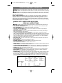 2
2
-
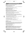 3
3
-
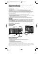 4
4
-
 5
5
-
 6
6
-
 7
7
-
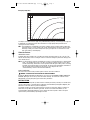 8
8
-
 9
9
-
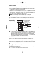 10
10
-
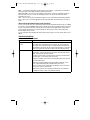 11
11
-
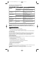 12
12
-
 13
13
-
 14
14
-
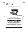 15
15
-
 16
16
-
 17
17
-
 18
18
-
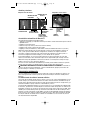 19
19
-
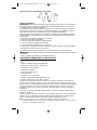 20
20
-
 21
21
-
 22
22
-
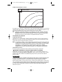 23
23
-
 24
24
-
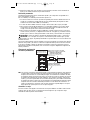 25
25
-
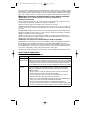 26
26
-
 27
27
-
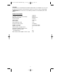 28
28
-
 29
29


Vector MAXX SST VEC049D Manual de usuario
- Categoría
- Adaptadores de corriente
- Tipo
- Manual de usuario
- Este manual también es adecuado para
en otros idiomas
- English: Vector MAXX SST VEC049D User manual
Artículos relacionados
Otros documentos
-
Black & Decker Marine Battery Manual de usuario
-
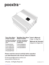 Pooxtra PXA3000MSW Manual de usuario
-
Black & Decker PI400AB Manual de usuario
-
-
-
-
Thor TH400 Instruction Manual And Warranty Information
-
Stanley PI500S Manual de usuario
-
-
