
USER MANUAL
CEILING FAN VENTILADOR DE TECHO


4
INDEX
ENGLISH
LIST OF PARTS 6
INSTALLATION PREPARATION 7
INSTALLATION INSTRUCTIONS 7
Security instructions 7
MOUNTING BRACKET ATTACHMENT 8
REMOTE CONTROL 8
REMOTE CONTROL CONNECTION 9
RECEIVER PLACEMENT 9
MOUNTING THE BLADES 10
ASSEMBLING THE CONNECTION PANEL 10
LED PANEL AND DECORATIVE SCREEN 10
CEILING FAN WITH LED LIGHT 10
ESPAÑOL
LISTA DE PARTES 12
PREPARACIÓN DE LA INSTALACIÓN 13
INSTRUCCIONES DE SEGURIDAD 13
INSTRUCCIONES DE INSTALACIÓN 13
FIJACIÓN DEL SOPORTE DE MONTAJE 14
MANDO A DISTANCIA 14
CONEXIÓN DEL MANDA A DISTANCIA 15
COLOCACIÓN DEL RECEPTOR 15
MONTAJE DE LAS ASPAS 16
ENSAMBLAJE DEL PANEL DE CONEXIONES 16
PANEL LED Y PANTALLA DECORATIVA 16
VENTILADOR DE TECHO CON LUZ LED 16
PORTUGUÊS
LISTA DE PEÇAS 18
PREPARAÇÃO DE INSTALAÇÃO 19
INSTRUÇÕES DE SEGURANÇA 19
INSTRUÇÕES DE INSTALAÇÃO 19
ANEXO DO SUPORTE DE MONTAGEM 20
CONTROLE REMOTO 20
CONEXÃO DE CONTROLE REMOTO 21
COLOCAÇÃO DO RECEPTOR 21
MONTAGEM DAS LÂMINAS 22
MONTAGEM DO PAINEL DE CONEXÃO 22
PAINEL DE LED E TELA DECORATIVA 22
VENTILADOR DE TETO COM LUZ LED 22
FRANÇAIS
LISTE DES PIÈCES 24
PRÉPARATION À L'INSTALLATION 25
CONSIGNES DE SÉCURITÉ 25
INSTRUCTIONS D'INSTALLATION 25
FIXATION DU SUPPORT DE MONTAGE 26
TÉLÉCOMMANDE 26
CONNEXION DE LA TÉLÉCOMMANDE 27
EMPLACEMENT DU RÉCEPTEUR 27
MONTAGE DES LAMES 28
ASSEMBLAGE DU PANNEAU DE CONNEXION 28
PANNEAU LED ET ÉCRAN DÉCORATIF 28
VENTILATEUR DE PLAFOND LED 28

5
ITALIANO
ELENCO DELLE PARTI 30
PREPARAZIONE ALL'INSTALLAZIONE 31
ISTRUZIONI PER L'INSTALLAZIONE 31
ISTRUZIONI DI SICUREZZA 31
ATTACCO STAFFA DI MONTAGGIO 32
TELECOMANDO 32
CONNESSIONE TELECOMANDO 33
POSIZIONAMENTO DEL RICEVITORE 33
MONTAGGIO LAME 34
MONTAGGIO DEL PANNELLO DI CONNESSIONE 34
PANNELLO LED E SCHERMO DECORATIVO 34
VENTILATORE DA SOFFITTO CON LUCE LED 34
DEUTSCH
TEILELISTE 36
INSTALLATIONSVORBEREITUNG 37
SICHERHEITSHINWEISE 37
INSTALLATIONSANLEITUNG 37
MONTAGEHALTERUNG BEFESTIGUNG 38
FERNBEDIENUNG 38
ANSCHLUSS DER FERNBEDIENUNG 39
EMPFÄNGERPLATZIERUNG 39
MONTAGE DER KLINGEN 40
MONTAGE DES ANSCHLUSSPANELS 40
LED-PANEL UND DEKORATIVER BILDSCHIRM 40
DECKENLÜFTER MIT LED-BELEUCHTUNG 40
NEDERLANDS
LIJST MET ONDERDELEN 42
INSTALLATIE VOORBEREIDING 43
BEVEILIGINGSINSTRUCTIES 43
INSTALLATIE INSTRUCTIES 43
MONTAGEBEUGEL BEVESTIGING 44
AFSTANDSBEDIENING 44
AANSLUITING AFSTANDSBEDIENING 45
PLAATSING ONTVANGER 45
DE MESSEN MONTEREN 46
HET VERBINDINGSPANEEL MONTEREN 46
LED-PANEEL EN DECORATIEF SCHERM 46
PLAFONDVENTILATOR MET LED-LICHT 46
POLSKI
LISTA CZĘŚCI 48
PRZYGOTOWANIE DO INSTALACJI 49
INSTRUKCJE BEZPIECZEŃSTWA 49
INSTRUKCJE INSTALACJI 49
MOCOWANIE WSPORNIKA MONTAŻOWEGO 50
ZDALNE STEROWANIE 50
POŁĄCZENIE ZDALNEGO STEROWANIA 51
UMIESZCZENIE ODBIORNIKA 51
MONTAŻ NOŻY 52
MONTAŻ PANELU POŁĄCZENIOWEGO 52
PANEL LED I EKRAN DEKORACYJNY 52
WENTYLATOR SUFITOWY OŚWIETLENIEM LED 52
INDEX

ENGLISH
6
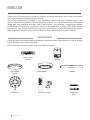
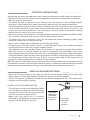
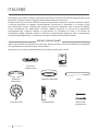
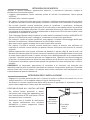
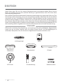
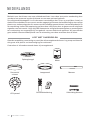
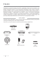
Remote control Expansion
bolts
Blades
Suspension
bracket Motor
LED panel
Decorative
screen Lamp panel
Thank you for choosing our ceiling fan. Before using the appliance, and to ensure the best
use, please read these instructions carefully.
The safety precautions included in this document reduce the risk of death, injury, and
electric shock when properly followed. Keep the manual in a safe place for future reference,
along with the complete warranty card, sales receipt, and package. If applicable, please
forward these instructions to the next owner of the appliance. Always follow basic safety
precautions and accident prevention measures when using an electrical appliance. We do
not assume any responsibility for the breach of these requirements by the customer.
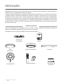
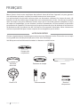
LIST OF PARTS
Carefully open the packaging and remove all included items. Place them on a rug or a large
piece of plastic to avoid any damage.
Check that all the items listed below have been included.
ENGLISH

7
ENGLISH
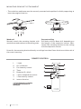
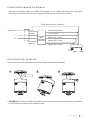
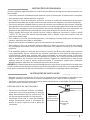
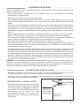
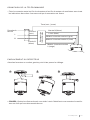
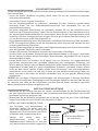
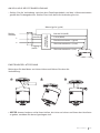
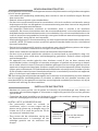
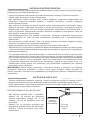
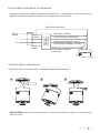
• To avoid personal injury and damage, make
sure the place to hang the sheets leaves a
clearance of 2.3 m from the ground and 76
cm from any walls or obstructions.
• Make sure the outlet box is securely
attached to the building structure and can
support the full weight of the fan.
INSTALLATION PREPARATION
76 cm of
separation
between
the wall or
obstacle. 2.3 m from
the blades
to the
ground
• Mark the correct position of the holes and x the ceiling bracket using the screws with
metal plugs or screws and washers suitable for the type of ceiling chosen.
• Check the correct installation of the bracket before hanging the fan. This plate must
support the full weight of the fan.
INSTALLATION INSTRUCTIONS
When using any electrical appliance, basic safety precautions should always be observed.
• Read this entire manual carefully before beginning installation. Save these instructions.
• Use only original spare parts.
• To reduce the risk of personal injury, connect the fan directly to the building support
structure in accordance with these instructions and use only the supplied hardware.
• To avoid possible electrical shock, before installing your fan, disconnect power by turning
off the circuit breakers in the outlet box and the associated wall switch location. If you
cannot lock the circuit breakers in the off position, securely attach a prominent warning
device, such as a tag, to the service panel.
• All wiring must be in accordance with national and local electrical codes and ANSI / NFPA
70. If you are unfamiliar with wiring, contact a qualied electrician.
• To reduce the risk of personal injury, do not bend the blade clamping system when
installing, balancing, or cleaning the fan.
• Never insert foreign objects between the rotating fan blades.
• To reduce the risk of re, electric shock, or motor damage, do not use a solid state speed
control with this fan. Use only original speed controls.
• This appliance can be used by children from 8 years of age and by people with reduced
physical, sensory or mental abilities or lack of experience and knowledge if they have
been supervised or instructed in the safe use of the appliance and understand the dangers
involved. Children must not play with the appliance. Children should not perform cleaning
or maintenance unless they are over 8 years old and supervised. Close supervision is
necessary when any appliance is used by or near children.
TIP: The important safety precautions and instructions in the manual are not intended to cover
all possible conditions and situations that may occur. It should be understood that common
sense and caution are necessary factors in the installation and operation of this fan.
SECURITY INSTRUCTIONS

ENGLISH
8
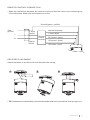
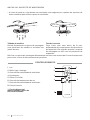
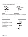
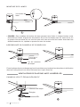
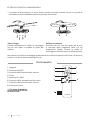
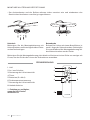
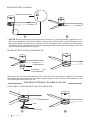
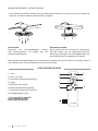
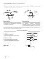
MOUNTING BRACKET ATTACHMENT
• The outlet box and beam must be securely mounted and capable of reliably supporting at
least the weight of the fan.
Wood roof
Securely attach the mounting bracket with
wood screws and washers to the ceiling joints.
Concrete ceiling
Drill holes with an 8mm drill, depending on
the length of the expansion screws. Next,
secure the mounting bracket to the ceiling
with the expansion screws.
Do not x the mounting bracket directly on ceilings less than 10mm thick to avoid the risk of
the screw loosening.
1. **Light
2. On / off button
3. Fan intensity control
4. Timer
5. Batteries (2 x AAA)
6. **Color temperature control
7. **Fan intensity control
8. Inverse function
REMOTE CONTROL
** Function only available
when the LED board is
installed.

9
ENGLISH
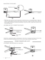
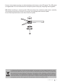
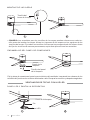
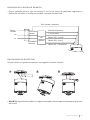
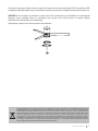
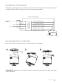
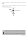
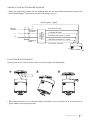
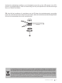
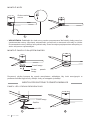
Attach the motor to the left hook, and then lead the wiring.
• TIP: Someone else should help you hold the ladder and hand you the fan after you get on it.
123
REMOTE CONTROL CONNECTION
RECEIVER PLACEMENT
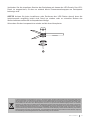
• Make the connection between the receiver wires and the fan motor wires following the
color indications. Make sure the connection is rm.
DC motor L (red)
Remote
control
receiver
Take
ground
L
N
L input
(black)
Input N
(white)
Neutral N (white)
L clear (blue)
DC motor L (pink)
DC motor L (gray)
Ground (green / yellow)

ENGLISH
10
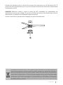
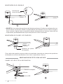
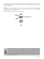
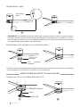
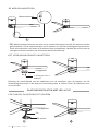
Blade arm screw
12
MOUNTING THE BLADES
• TIP: Blade bolt washers can be attached to each bolt prior to installing blades. Align the
juicers on the blades with the screw holes on the motor. Tighten all the screws once you
have hooked the blades. Before permanently xing the screws, repeat this process with
the remaining ones.
Lamp panel
Lamp panel
screw
ASSEMBLING THE CONNECTION PANEL
Attach the connection plate to the bottom of the fan by inserting the heads of the xing
screws into the holes intended for this. Drive in the screws and then secure them.
Pin
LED panel
12
CEILING FAN WITH LED LIGHT
LED PANEL AND DECORATIVE SCREEN
Lamp panel

11
ENGLISH
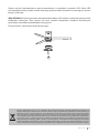
Connect the single-pin plugs on the backplane with those on the LED panel. The LED panel
is magnetized so it will be attached to the patch panel simply by snapping them together.
TIP: While installing or removing the LED board, keep the insulation pads intact carefully.
Turning the setscrews too hard or too quickly will damage the insulation pads.
Screw the lampshade back onto the connection plate.
3
In compliance with Directives: 2012/19/EU and 2015/863/EU on the restriction of the use of dangerous substances in elec-
tric and electronic equipment as well as their waste disposal. The symbol with the crossed dustbin shown on the package
indicates that the product at the end of its service life shall be collected as separate waste. Therefore, any products that
have reached the end of their useful life must be given to waste disposal centres specialising in separate collection of
waste electrical and electronic equipment, or given back to the retailer at the time of purchasing new similar equipment,
on a one for one basis. The adequate separate collection for the subsequent start-up of the equipment sent to be recycled,
treated and disposed of in an environmentally compatible way contributes to preventing possible negative effects on the
environment and health and optimises the recycling and reuse of components making up the apparatus. Abusive disposal
of the product by the user involves application of the administrative sanctions according to the laws.

12 ESPAÑOL
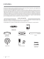
Control remoto Tornillos de
expansión
Aspas
Soporte de
suspensión
Panel LED
Pantalla
decorativa Panel de la lámpara
Gracias por elegir nuestro ventilador de techo. Antes de utilizar el aparato, y para garantizar
el mejor uso, lea atentamente estas instrucciones.
Las precauciones de seguridad incluidas en este documento reducen el riesgo de muerte,
lesiones y descargas eléctricas cuando se cumplen correctamente. Guarde el manual en un
lugar seguro para futuras consultas, junto con la tarjeta de garantía completa, el recibo de
compra y el paquete. Si corresponde, transmita estas instrucciones al próximo propietario
del aparato. Siga siempre las precauciones básicas de seguridad y las medidas de prevención
de accidentes cuando utilice un aparato eléctrico. No asumimos ninguna responsabilidad
por el incumplimiento de estos requisitos por parte del cliente.
LISTA DE PARTES
Abra con cuidado el embalaje y retire todos los elementos incluidos. Colócalos sobre una
alfombra o un gran trozo de plástico para evitar cualquier daño.
Compruebe que se hayan incluido todos los elementos que se enumeran a continuación.
ESPAÑOL
Motor

13
ESPAÑOL
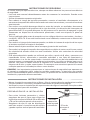
• Para evitar lesiones personales y daños,
asegúrese de que el lugar para colgar las
hojas deje un espacio libre de 2,3 m del suelo
y 76 cm de cualquier pared u obstrucción.
• Asegúrese de que la caja de distribución
esté bien sujeta a la estructura del edicio
y pueda soportar todo el peso del ventilador.
PREPARACIÓN DE LA INSTALACIÓN
76 cm de
separación
entre la pared
u obstáculo. 2,3 m de
las aspas al
suelo
Al utilizar cualquier aparato eléctrico, siempre se deben observar las precauciones básicas
de seguridad.
• Lea todo este manual detenidamente antes de comenzar la instalación. Guarde estas
instrucciones.
• Utilice únicamente repuestos originales.
• Para reducir el riesgo de lesiones personales, conecte el ventilador directamente a la
estructura de soporte del edicio de acuerdo con estas instrucciones y use solo el hardware
suministrado.
• Para evitar una posible descarga eléctrica, antes de instalar su ventilador, desconecte
la energía apagando los disyuntores de la caja de salida y la ubicación del interruptor de
pared asociado. Si no puede bloquear los disyuntores en la posición de apagado, sujete
rmemente un dispositivo de advertencia prominente, como una etiqueta, al panel de
servicio.
• Todo el cableado debe estar de acuerdo con los códigos eléctricos nacionales y locales y
con ANSI / NFPA 70. Si no está familiarizado con el cableado, contacte con un electricista
cualicado.
• Para reducir el riesgo de lesiones personales, no doble el sistema de sujeción de las aspas
al instalar, equilibrar o limpiar el ventilador.
• Nunca inserte objetos extraños entre las aspas giratorias del ventilador.
• Para reducir el riesgo de incendio, descarga eléctrica o daños al motor, no utilice un control
de velocidad de estado sólido con este ventilador. Utilice solo controles de velocidad
originales.
• Este electrodoméstico puede ser utilizado por niños a partir de 8 años y personas con
capacidades físicas, sensoriales o mentales reducidas o con falta de experiencia y
conocimiento si se les ha supervisado o instruido sobre el uso del electrodoméstico de
manera segura y comprenden las peligros involucrados. Los niños no deben jugar con el
aparato. Los niños no deben realizar la limpieza ni el mantenimiento, a menos que sean
mayores de 8 años y estén supervisados. Es necesaria una estrecha supervisión cuando
cualquier aparato es utilizado por niños o cerca de ellos.
CONSEJO: Las importantes precauciones e instrucciones de seguridad que aparecen en
el manual no pretenden cubrir todas las posibles condiciones y situaciones que pueden
ocurrir. Debe entenderse que el sentido común y la precaución son factores necesarios en la
instalación y operación de este ventilador.
• Marcar la posición correcta de los oricios y jar el soporte de techo mediante los tornillos
con taco metálico o tornillos y arandelas adecuados al tipo de techo elegido.
• Verique la correcta instalación del soporte antes de colgar el ventilador. Esta placa debe
soportar todo el peso del ventilador.
INSTRUCCIONES DE INSTALACIÓN
INSTRUCCIONES DE SEGURIDAD

14 ESPAÑOL
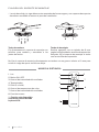
FIJACIÓN DEL SOPORTE DE MONTAJE
• La caja de salida y la viga deben estar montadas de forma segura y ser capaces de soportar
de manera conable al menos el peso del ventilador.
Techo de madera
Fije rmemente el soporte de montaje con
tornillos para madera y arandelas a las
juntas del techo.
Techo de hormigón
Realice agujeros con un taladro de 8 mm,
según la longitud de los tornillos de expansión.
Después, je el soporte de montaje al techo
con los tornillos de expansión.
No je el soporte de montaje directamente en techos con un grosor inferior a 10 mm para
evitar el riesgo de que el tornillo se aoje.
1. Luz
2. Botón ON / OFF
3. Control de intensidad del ventilador
4. Temporizador
5. Pilas (2 x AAA)
6. Control de temperatura de color
7. Control de intensidad del ventilador.
8. Función inversa
1
3
2
4
5
8
7
6
MANDO A DISTANCIA
** Función solo disponible
cuando se tiene instalada
la placa LED.

15
ESPAÑOL
Conecte el motor en el gancho izquierdo y luego conduzca el cableado.
• CONSEJO: Otra persona debería ayudarle para sostener la escalera de mano y alcanzarle
el ventilador una vez se haya subido a esta.
123
CONEXIÓN DEL MANDA A DISTANCIA
COLOCACIÓN DEL RECEPTOR
• Realice la conexión entre los cables del receptor y los cables del motor del ventilador
siguiendo las indicaciones de color. Asegúrese de que la conexión esté rme.
Motor DC L (rojo)
Receptor
del
mando a
distancia
Toma tierra
L
N
Entrada L
(negro)
Entrada N
(blanco)
Neutro N (blanco)
L claro (azul)
Motor DC L (rosa)
Motor DC L (gris)
Toma tierra (verde / amarilla)

16 ESPAÑOL
Tornillo del
brazo de la aspa
12
MONTAJE DE LAS ASPAS
• CONSEJO: Las arandelas para los tornillos de las aspas pueden colocarse en cada tor-
nillo antes de instalar las aspas. Alinee los jugueros de las aspas con los agujeros de los
tornillos del motor. Fije todos los tornillos una vez que haya enganchado las aspas. Antes
de jar los tornillos de manera permanente, repita este proceso con las restantes.
Panel de la
lámpara
Tornillo del panel
de la lámpara
ENSAMBLAJE DEL PANEL DE CONEXIONES
Fije la placa de conexiones hasta la parte inferior del ventilador insertando las cabezas de los
tornillos de jación en los oricios destinados a ello. Enroque los tornillos y después asegúrelos.
Pin
Panel LED
12
VENTILADOR DE TECHO CON LUZ LED
PANEL LED Y PANTALLA DECORATIVA
Panel de la lámpara

17
ESPAÑOL
Conecte los enchufes de un solo pin de la placa de conexiones con los del panel LED. El
panel LED está magnetizado, por lo que se adjuntará al panel de conexiones simplemente
colocándolos juntos.
CONSEJO: Mientras instala o retira la placa de LED, mantenga las almohadillas de
aislamiento intactas con cuidado. Si gira los tornillos de jación con demasiada fuerza o
rápidamente, se dañarán las almohadillas de aislamiento.
Vuelva a atornillar la pantalla de la lámpara a la placa de conexiones.
3
En cumplimiento de las directivas: 2012/19 / UE y 2015/863 / UE sobre la restricción del uso de sustancias peligrosas en
equipos eléctricos y electrónicos, así como su eliminación de residuos. El símbolo con el cubo de basura cruzado que se
muestra en el paquete indica que el producto al nal de su vida útil se recogerá como residuo separado. Por lo tanto, cualquier
producto que haya llegado al nal de su vida útil debe entregarse a centros de eliminación de residuos especializados en la
recogida selectiva de equipos eléctricos y electrónicos de desecho, o devolverse al minorista al momento de comprar equipos
nuevos similares, en uno para Una base. La recolección separada adecuada para la posterior puesta en marcha de los equipos
enviados para ser reciclados, tratados y eliminados de una manera compatible con el medio ambiente contribuye a prevenir
posibles efectos negativos sobre el medio ambiente y la salud y optimiza el reciclaje y la reutilización de los componentes
que componen el aparato. La eliminación abusiva del producto por parte del usuario implica la aplicación de las sanciones
administrativas de acuerdo con las leyes.

18 PORTUGUÊS
Controle remoto Parafusos de
expansão
Lâminas
Suporte de
suspensão
Painel de LED
Tela
decorativa
Painel de lâmpada
Obrigado por escolher nosso ventilador de teto. Antes de usar o aparelho, e para garantir o
melhor uso, leia atentamente estas instruções.
As precauções de segurança incluídas neste documento reduzem o risco de morte, ferimentos
e choque elétrico quando devidamente seguidas. Guarde o manual em local seguro para
referência futura, junto com o cartão de garantia completo, recibo de venda e embalagem.
Se aplicável, encaminhe estas instruções ao próximo proprietário do aparelho. Sempre siga
as precauções básicas de segurança e as medidas de prevenção de acidentes ao usar um
aparelho elétrico. Não assumimos qualquer responsabilidade pela violação destes requisitos
por parte do cliente.
LISTA DE PEÇAS
Abra a embalagem com cuidado e remova todos os itens incluídos. Coloque-os sobre um
tapete ou um pedaço grande de plástico para evitar danos.
Verique se todos os itens listados abaixo foram incluídos.
PORTUGUÊS
Motor

19
PORTUGUÊS
• Para evitar ferimentos e danos, certique-
se de que o local para pendurar os lençóis
deixa uma distância de 2,3 m do solo e 76
cm de quaisquer paredes ou obstruções.
• Certique-se de que a caixa de tomadas
esteja rmemente presa à estrutura do
prédio e possa suportar todo o peso do
ventilador.
PREPARAÇÃO DE INSTALAÇÃO
76 cm de
separação
entre a parede
ou obstáculo. 2,3 m das
lâminas ao
solo
Ao usar qualquer aparelho elétrico, as precauções básicas de segurança devem sempre ser
observadas.
• Leia todo o manual cuidadosamente antes de iniciar a instalação. Guarde essas instruções.
• Use apenas peças sobressalentes originais.
• Para reduzir o risco de acidentes pessoais, conecte o ventilador diretamente à estrutura
de suporte do prédio de acordo com estas instruções e use apenas o hardware fornecido.
• Para evitar possível choque elétrico, antes de instalar seu ventilador, desconecte a energia
desligando os disjuntores na caixa de tomadas e o local do interruptor de parede associado.
Se você não conseguir travar os disjuntores na posição desligada, xe com segurança um
dispositivo de advertência proeminente, como uma etiqueta, ao painel de serviço.
• Toda a ação deve estar de acordo com os códigos elétricos nacionais e locais e ANSI
/ NFPA 70. Se você não estiver familiarizado com a ação, entre em contato com um
eletricista qualicado.
• Para reduzir o risco de ferimentos pessoais, não dobre o sistema de xação da lâmina ao
instalar, equilibrar ou limpar o ventilador.
• Nunca insira objetos estranhos entre as pás rotativas do ventilador.
• Para reduzir o risco de incêndio, choque elétrico ou danos ao motor, não use um controle
de velocidade de estado sólido com este ventilador. Use apenas controles de velocidade
originais.
• Este aparelho pode ser utilizado por crianças a partir dos 8 anos de idade e por pessoas
com capacidades físicas, sensoriais ou mentais reduzidas ou com falta de experiência e
conhecimento, desde que tenham sido supervisionadas ou instruídas sobre a utilização
segura do aparelho e compreendam os perigos envolvidos. As crianças não devem brincar
com o aparelho. As crianças não devem realizar limpeza ou manutenção a menos que
tenham mais de 8 anos e sejam supervisionadas. É necessária supervisão cuidadosa
quando qualquer aparelho for usado por ou perto de crianças.
GORJETA: As importantes precauções de segurança e instruções no manual não se destinam
a cobrir todas as condições e situações possíveis que podem ocorrer. Deve ser entendido que
bom senso e cautela são fatores necessários na instalação e operação deste ventilador.
• Marque a posição correta dos furos e xe o suporte de teto utilizando os parafusos com
plugues de metal ou parafusos e arruelas adequados para o tipo de teto escolhido.
• Verique a instalação correta do suporte antes de pendurar o ventilador. Esta placa deve
suportar todo o peso do ventilador.
INSTRUÇÕES DE INSTALAÇÃO
INSTRUÇÕES DE SEGURANÇA

20 PORTUGUÊS
ANEXO DO SUPORTE DE MONTAGEM
• A caixa de saída e a viga devem ser montadas com segurança e capazes de suportar de
forma conável pelo menos o peso do ventilador.
Telhado de madeira
Prenda rmemente o suporte de montagem
com parafusos de madeira e arruelas nas
juntas do teto.
Teto de concreto
Faça furos com uma broca de 8 mm,
dependendo do comprimento dos parafusos
de expansão. Em seguida, prenda o suporte
de montagem ao teto com os parafusos de
expansão.
Não xe o suporte de montagem diretamente em tetos com menos de 10 mm de espessura
para evitar o risco de afrouxamento do parafuso.
1. Luz
2. Botão ligar / desligar
3. Controle de intensidade do ventilador
4. Cronômetro
5. Pilhas (2 x AAA)
6. Controle de temperatura de cor
7. Controle de intensidade do ventilador.
8. Função inversa
1
3
2
4
5
8
7
6
CONTROLE REMOTO
** Função disponível
apenas quando a placa de
LED está instalada.

21
PORTUGUÊS
Prenda o motor ao gancho esquerdo e, em seguida, conduza a ação.
• GORJETA: Alguém deve ajudá-lo a segurar a escada e lhe entregar o leque depois que você
subir nele.
123
CONEXÃO DE CONTROLE REMOTO
COLOCAÇÃO DO RECEPTOR
• Faça a conexão entre os os do receptor e os os do motor do ventilador seguindo as
indicações coloridas. Certique-se de que a conexão esteja rme.
Motor DC L (vermelho)
Receptor
de
controle
remoto
Tomar
terreno
eu
N
Entrada L
(preto)
Entrada N
(branco)
Neutro N (branco)
L claro (azul)
Motor DC L (rosa)
Motor DC L (cinza)
Solo (verde / amarelo)

22 PORTUGUÊS
Parafuso do
braço da lâmina
12
MONTAGEM DAS LÂMINAS
• GORJETA: As arruelas dos parafusos das lâminas podem ser xadas em cada parafuso an-
tes de instalar as lâminas. Alinhe os espremedores nas lâminas com os orifícios dos para-
fusos no motor. Aperte todos os parafusos depois de enganchar as lâminas. Antes de xar
os parafusos permanentemente, repita este processo com os restantes.
Painel de
lâmpada
Parafuso do painel
da lâmpada
MONTAGEM DO PAINEL DE CONEXÃO
Fixe a placa de conexão na parte inferior do ventilador inserindo as cabeças dos parafusos
de xação nos orifícios destinados a isso. Insira os parafusos e xe-os.
Alnete
Painel de LED
12
VENTILADOR DE TETO COM LUZ LED
PAINEL DE LED E TELA DECORATIVA
Painel de lâmpada

23
PORTUGUÊS
Conecte os plugues de pino único no painel traseiro com os do painel de LED. O painel de LED
é magnetizado para que seja conectado ao painel de conexão simplesmente encaixando-os.
GORJETA: Ao instalar ou remover a placa de LED, mantenha as almofadas de isolamento
intactas com cuidado. Girar os parafusos de ajuste com muita força ou muito rápido
danicará as almofadas de isolamento.
Aparafuse o abajur de volta na placa de conexão.
3
Em conformidade com as diretrizes: 2012/19 / UE e 2015/863 / UE sobre a restrição do uso de substâncias perigosas em
equipamentos elétricos e eletrônicos, bem como a eliminação de resíduos. O símbolo com o caixote do lixo cruzado mostrado
na embalagem indica que o produto ao nal de sua vida útil será coletado como lixo separado. Portanto, qualquer produto
que tenha atingido o m de sua vida útil deve ser entregue a centros especializados de eliminação de resíduos para coleta
seletiva de equipamentos elétricos e eletrônicos, ou devolvido ao varejista ao comprar equipamentos novos similares, em um
para uma base. A coleta seletiva apropriada para o comissionamento subsequente do equipamento enviado para reciclagem,
tratamento e descarte de maneira ecológica ajuda a evitar possíveis efeitos negativos no meio ambiente e na saúde e otimiza
a reciclagem e reutilização de os componentes que compõem o dispositivo. . A eliminação abusiva do produto pelo usuário
implica a aplicação de sanções administrativas de acordo com as leis.

24 FRANÇAIS
Télécommande Boulons
d'expansion
Lames
Support de
suspension Moteur
Paravent
décoratif
Panneau de lampe
Merci d'avoir choisi notre ventilateur de plafond. Avant d'utiliser l'appareil, et pour garantir
une utilisation optimale, veuillez lire attentivement ces instructions.
Les précautions de sécurité incluses dans ce document réduisent le risque de mort, de
blessure et de choc électrique lorsqu'elles sont correctement suivies. Conservez le manuel
dans un endroit sûr pour référence future, ainsi que la carte de garantie complète, le reçu
de vente et l'emballage. Le cas échéant, veuillez transmettre ces instructions au prochain
propriétaire de l'appareil. Suivez toujours les précautions de sécurité de base et les mesures
de prévention des accidents lors de l'utilisation d'un appareil électrique. Nous n'assumons
aucune responsabilité pour le non-respect de ces exigences par le client.
LISTE DES PIÈCES
Ouvrez soigneusement l'emballage et retirez tous les éléments inclus. Placez-les sur un tapis
ou un grand morceau de plastique pour éviter tout dommage.
Vériez que tous les éléments énumérés ci-dessous ont été inclus.
FRANÇAIS
Panel LED

25
FRANÇAIS
• Pour éviter les blessures et les dommages,
assurez-vous que l'endroit pour accrocher
les feuilles laisse un dégagement de 2,3 m
du sol et de 76 cm de tout mur ou obstacle.
• Assurez-vous que la boîte de sortie
est solidement xée à la structure du
bâtiment et peut supporter tout le poids du
ventilateur.
PRÉPARATION À L'INSTALLATION
76 cm de
séparation
entre le mur
ou l'obstacle. 2,3 m des
pales au sol
Lors de l'utilisation de tout appareil électrique, des précautions de sécurité de base doivent
toujours être observées.
• Lisez attentivement l'intégralité de ce manuel avant de commencer l'installation.
Enregistrez ces instructions.
• N'utilisez que des pièces de rechange d'origine.
• Pour réduire le risque de blessures, connectez le ventilateur directement à la structure de
support du bâtiment conformément à ces instructions et utilisez uniquement le matériel
fourni.
• Pour éviter tout choc électrique, avant d'installer votre ventilateur, débranchez l'alimentation
en éteignant les disjoncteurs dans la boîte de sortie et l'emplacement de l'interrupteur
mural associé. Si vous ne pouvez pas verrouiller les disjoncteurs en position d'arrêt, xez
solidement un dispositif d'avertissement bien visible, tel qu'une étiquette, au panneau de
service.
• Tout le câblage doit être conforme aux codes électriques nationaux et locaux et ANSI /
NFPA 70. Si vous n'êtes pas familier avec le câblage, contactez un électricien qualié.
• Pour réduire le risque de blessures corporelles, ne pliez pas le système de serrage des
pales lors de l'installation, de l'équilibrage ou du nettoyage du ventilateur.
• N'insérez jamais d'objets étrangers entre les pales du ventilateur en rotation.
• Pour réduire le risque d'incendie, de choc électrique ou de dommages au moteur, n'utilisez
pas de commande de vitesse à semi-conducteurs avec ce ventilateur. N'utilisez que des
commandes de vitesse d'origine.
• Cet appareil peut être utilisé par des enfants à partir de 8 ans et par des personnes ayant
des capacités physiques, sensorielles ou mentales réduites ou un manque d'expérience et
de connaissances si elles ont été supervisées ou instruites sur l'utilisation sûre de l'appareil
et comprennent les dangers encourus. Les enfants ne doivent pas jouer avec l'appareil. Les
enfants ne doivent pas effectuer de nettoyage ou d'entretien à moins qu'ils n'aient plus de
8 ans et qu'ils soient supervisés. Une surveillance étroite est nécessaire lorsqu'un appareil
est utilisé par ou à proximité d'enfants.
CONSEIL: Les précautions de sécurité importantes et les instructions contenues dans le
manuel ne sont pas destinées à couvrir toutes les conditions et situations possibles qui
peuvent se produire. Il faut comprendre que le bon sens et la prudence sont des facteurs
nécessaires dans l'installation et le fonctionnement de ce ventilateur.
• Marquez la position correcte des trous et xez le support de plafond à l'aide des vis avec
chevilles métalliques ou vis et rondelles adaptées au type de plafond choisi.
• Vériez la bonne installation du support avant de suspendre le ventilateur. Cette plaque
doit supporter tout le poids du ventilateur.
INSTRUCTIONS D'INSTALLATION
CONSIGNES DE SÉCURITÉ

26 FRANÇAIS
FIXATION DU SUPPORT DE MONTAGE
• La boîte de sortie et la poutre doivent être solidement xées et capables de supporter de
manière able au moins le poids du ventilateur.
Toit en bois
Fixez solidement le support de montage
avec des vis à bois et des rondelles aux joints
du plafond.
Plafond en béton
Percez des trous avec un foret de 8 mm, en
fonction de la longueur des vis d'expansion.
Ensuite, xez le support de montage au
plafond avec les vis d'expansion.
Ne pas xer le support de xation directement sur des plafonds de moins de 10 mm
d'épaisseur pour éviter le risque de desserrage de la vis.
1. Léger
2. Bouton ON/OFF
3. Contrôle de l'intensité du ventilateur
4. Minuteur
5. Piles (2 x AAA)
6. Contrôle de la température de couleur
7. Contrôle de l'intensité du ventilateur.
8. Fonction inverse
1
3
2
4
5
8
7
6
TÉLÉCOMMANDE
** Fonction disponible
uniquement lorsque la
carte LED est installée.

27
FRANÇAIS
Attachez le moteur au crochet gauche, puis faites passer le câblage.
• CONSEIL: Quelqu'un d'autre devrait vous aider à tenir l'échelle et vous remettre le ventila-
teur une fois que vous êtes monté dessus.
123
CONNEXION DE LA TÉLÉCOMMANDE
EMPLACEMENT DU RÉCEPTEUR
• Faire la connexion entre les ls du récepteur et les ls du moteur du ventilateur en suivant
les indications de couleur. Assurez-vous que la connexion est ferme.
Moteur à courant continu
L (rouge)
Récepteur de
télécommande
Prendre du
terrain
L
N
Entrée L
(noir)
Entrée N
(blanc)
Neutre N (blanc)
L clair (bleu)
Moteur à courant continu L (rose)
Moteur à courant continu L (gris)
Terre (vert / jaune)

28 FRANÇAIS
Vis de bras de
lame
12
MONTAGE DES LAMES
• CONSEIL: Des rondelles de boulon de lame peuvent être xées à chaque boulon avant
d'installer les lames. Alignez les extracteurs de jus sur les lames avec les trous de vis sur
le moteur. Serrez toutes les vis une fois que vous avez accroché les lames. Avant de xer
dénitivement les vis, répétez ce processus avec les autres.
Panneau
de lampe
Vis de panneau
de lampe
ASSEMBLAGE DU PANNEAU DE CONNEXION
Fixez la plaque de raccordement au bas du ventilateur en insérant les têtes des vis de xation
dans les trous prévus à cet effet. Enfoncez les vis puis xez-les.
Épingler
Panneau DEL
12
VENTILATEUR DE PLAFOND AVEC LUMIÈRE LED
PANNEAU LED ET ÉCRAN DÉCORATIF
Panneau de lampe

29
FRANÇAIS
Connectez les ches à broche unique du fond de panier à celles du panneau LED. Le panneau
LED est magnétisé de sorte qu'il sera xé au panneau de brassage simplement en les
enclenchant ensemble.
CONSEIL: Lors de l'installation ou du retrait de la carte LED, gardez soigneusement
les coussinets isolants intacts. Tourner les vis de réglage trop fort ou trop rapidement
endommagera les coussinets isolants.
Revissez l'abat-jour sur la plaque de raccordement.
3
Conformément aux directives: 2012/19 / UE et 2015/863 / UE sur la limitation de l'utilisation de substances dangereuses dans
les équipements électriques et électroniques, ainsi que leur élimination des déchets. Le symbole avec la poubelle croisée
indiqué sur l'emballage indique que le produit à la n de sa durée de vie sera collecté en tant que déchet séparé. Par consé-
quent, tout produit ayant atteint la n de sa durée de vie doit être livré dans des centres d'élimination des déchets spécialisés
pour la collecte sélective des déchets d'équipements électriques et électroniques, ou retourné au détaillant lors de l'achat
de nouveaux équipements similaires, en un seul pour une base. Une collecte séparée appropriée pour la mise en service
ultérieure des équipements expédiés pour être recyclés, traités et éliminés d'une manière respectueuse de l'environnement
aide à prévenir les effets négatifs potentiels sur l'environnement et la santé et optimise le recyclage et la réutilisation des les
composants qui composent l'appareil. L'élimination abusive du produit par l'utilisateur implique l'application de sanctions
administratives conformément aux lois.

30 ITALIANO
Telecomando Bulloni ad
espansione
lame
Staffa di
sospensione
Il motore
Pannello LED
Schermo
decorativo
Pannello lampada
Grazie per aver scelto il nostro ventilatore da softto. Prima di utilizzare l'apparecchio, e per
garantire il miglior utilizzo, leggere attentamente queste istruzioni.
Le precauzioni di sicurezza incluse in questo documento riducono il rischio di morte, lesioni
e scosse elettriche se seguite correttamente. Conservare il manuale in un luogo sicuro
per riferimento futuro, insieme alla scheda di garanzia completa, alla ricevuta di vendita
e alla confezione. Se applicabile, inoltrare queste istruzioni al successivo proprietario
dell'apparecchio. Seguire sempre le precauzioni di sicurezza di base e le misure di
prevenzione degli incidenti quando si utilizza un apparecchio elettrico. Non ci assumiamo
alcuna responsabilità per la violazione di questi requisiti da parte del cliente.
ELENCO DELLE PARTI
Aprire con cautela la confezione e rimuovere tutti gli articoli inclusi. Posizionali su un tappeto
o un grande pezzo di plastica per evitare danni.
Vericare che tutti gli elementi elencati di seguito siano stati inclusi.
ITALIANO

31
ITALIANO
• Per evitare lesioni personali e danni,
assicurarsi che il luogo per appendere i teli
lasci una distanza di 2,3 m da terra e 76 cm
da eventuali muri o ostacoli.
• Assicurarsi che la scatola di derivazione
sia ssata saldamente alla struttura
dell'edicio e possa supportare l'intero
peso del ventilatore.
PREPARAZIONE ALL'INSTALLAZIONE
76 cm di
distanza
tra il muro o
l'ostacolo. 2,3 m dalle
lame al
suolo
Quando si utilizza qualsiasi apparecchio elettrico, è necessario osservare sempre le
precauzioni di sicurezza di base.
• Leggere attentamente l'intero manuale prima di iniziare l'installazione. Salva queste
istruzioni.
• Utilizzare solo ricambi originali.
• Per ridurre il rischio di lesioni personali, collegare il ventilatore direttamente alla struttura
di supporto dell'edicio secondo queste istruzioni e utilizzare solo l'hardware in dotazione.
• Per evitare possibili scosse elettriche, prima di installare il ventilatore, scollegare
l'alimentazione spegnendo gli interruttori di circuito nella scatola delle prese e la posizione
dell'interruttore a parete associata. Se non è possibile bloccare gli interruttori automatici
in posizione di spegnimento, ssare saldamente un dispositivo di avviso ben visibile, come
un'etichetta, al pannello di servizio.
• Tutti i cablaggi devono essere conformi ai codici elettrici nazionali e locali e ANSI/NFPA 70.
Se non si ha familiarità con il cablaggio, contattare un elettricista qualicato.
• Per ridurre il rischio di lesioni personali, non piegare il sistema di bloccaggio delle pale
durante l'installazione, il bilanciamento o la pulizia della ventola.
• Non inserire mai oggetti estranei tra le pale rotanti della ventola.
• Per ridurre il rischio di incendi, scosse elettriche o danni al motore, non utilizzare un
controllo di velocità a stato solido con questa ventola. Utilizzare solo controlli di velocità
originali.
• Questo apparecchio può essere utilizzato da bambini a partire dagli 8 anni di età e da
persone con ridotte capacità siche, sensoriali o mentali o prive di esperienza e conoscenza
se sono state supervisionate o istruite sull'uso sicuro dell'apparecchio e ne comprendono
i pericoli. I bambini non devono giocare con l'apparecchio. I bambini non devono eseguire
la pulizia o la manutenzione a meno che non abbiano più di 8 anni e non siano sorvegliati.
È necessaria un'attenta supervisione quando un apparecchio viene utilizzato da o vicino a
bambini.
CONSIGLIO: Le importanti precauzioni di sicurezza e le istruzioni nel manuale non
intendono coprire tutte le possibili condizioni e situazioni che possono vericarsi. Dovrebbe
essere chiaro che il buon senso e la cautela sono fattori necessari nell'installazione e nel
funzionamento di questo ventilatore.
• Segnare la corretta posizione dei fori e ssare la staffa a softto utilizzando le viti con
tasselli metallici o viti e rondelle adatte al tipo di softto scelto.
• Vericare la corretta installazione della staffa prima di appendere il ventilatore. Questa
piastra deve supportare l'intero peso del ventilatore.
ISTRUZIONI PER L'INSTALLAZIONE
ISTRUZIONI DI SICUREZZA

32 ITALIANO
ATTACCO STAFFA DI MONTAGGIO
• La scatola di derivazione e la trave devono essere montate in modo sicuro e in grado di
sostenere in modo afdabile almeno il peso del ventilatore.
Tetto in legno
Fissare saldamente la staffa di montaggio
con viti per legno e rondelle ai giunti del
softto.
Softto in cemento
Praticare dei fori con una punta da 8 mm,
a seconda della lunghezza delle viti ad
espansione. Quindi, ssare la staffa di
montaggio al softto con le viti ad espansione.
Non ssare la staffa di montaggio direttamente su softti di spessore inferiore a 10 mm per
evitare il rischio di allentamento della vite.
1. Leggero
2. Pulsante ON/OFF
3. Controllo dell'intensità della ventola
4. Timer
5. Batterie (2 x AAA)
6. Controllo della temperatura del colore
7. Controllo dell'intensità della ventola.
8. Funzione inversa
1
3
2
4
5
8
7
6
TELECOMANDO
** Funzione disponibile
solo quando è installata
la scheda LED.

33
ITALIANO
Attaccare il motore al gancio sinistro, quindi condurre il cablaggio.
• CONSIGLIO: Qualcun altro dovrebbe aiutarti a tenere la scala e darti il ventilatore dopo
che ci sei salito.
123
CONNESSIONE TELECOMANDO
POSIZIONAMENTO DEL RICEVITORE
• Effettuare il collegamento tra i li del ricevitore ei li del motore del ventilatore seguendo
le indicazioni del colore. Assicurati che la connessione sia stabile.
Motore CC L (rosso)
Ricevitore
telecomando
Prendere
terra
l
N
Ingresso L
(nero)
Ingresso
N (bianco)
Neutro N (bianco)
L trasparente (blu)
Motore CC L (rosa)
Motore DC L (grigio)
Terra (verde/giallo)

34 DEUTSCH
Vite braccio
lama
12
MONTAGGIO LAME
• CONSIGLIO: Le rondelle dei bulloni della lama possono essere ssate a ciascun bullone
prima di installare le lame. Allineare gli spremiagrumi sulle lame con i fori delle viti sul mo-
tore. Stringere tutte le viti una volta agganciate le lame. Prima di ssare denitivamente le
viti, ripetere questa procedura con le restanti.
Pannello
lampada
Vite pannello
lampada
MONTAGGIO DEL PANNELLO DI CONNESSIONE
Fissare la piastra di collegamento alla parte inferiore del ventilatore inserendo le teste delle
viti di ssaggio nei fori previsti. Avvitare le viti e poi ssarle.
Spillo
Pannello LED
12
VENTILATORE DA SOFFITTO CON LUCE LED
PANNELLO LED E SCHERMO DECORATIVO
Pannello lampada

35
DEUTSCH
Collegare le spine unipolari sul backplane con quelle sul pannello LED. Il pannello LED è
magnetizzato, quindi sarà attaccato al pannello patch semplicemente facendoli scattare
insieme.
CONSIGLIO: Durante l'installazione o la rimozione della scheda LED, mantenere intatti
i cuscinetti isolanti con cura. Girare le viti di ssaggio troppo forte o troppo velocemente
danneggerà i cuscinetti isolanti.
Riavvitare il paralume sulla piastra di collegamento.
3
In conformità con le direttive: 2012/19 / UE e 2015/863 / UE sulla restrizione dell'uso di sostanze pericolose nelle appa-
recchiature elettriche ed elettroniche, nonché sul loro smaltimento dei riuti. Il simbolo con la pattumiera incrociata mostrato
sulla confezione indica che il prodotto al termine della sua vita utile verrà raccolto come riuto separato. Pertanto, qualsiasi
prodotto che ha raggiunto la ne della sua vita utile deve essere consegnato a centri specializzati di smaltimento dei riuti per
la raccolta selettiva di riuti di apparecchiature elettriche ed elettroniche o restituito al rivenditore al momento dell'acquisto di
nuove apparecchiature simili, in un'unica per una base. Una corretta raccolta separata per la successiva messa in servizio di
apparecchiature spedite per essere riciclate, trattate e smaltite in modo ecologico aiuta a prevenire potenziali effetti negativi
sull'ambiente e sulla salute e ottimizza il riciclaggio e il riutilizzo di i componenti che compongono il dispositivo. L'eliminazione
abusiva del prodotto da parte dell'utente implica l'applicazione di sanzioni amministrative in conformità con le leggi.

36 DEUTSCH
Fernbedienung Dehnschrauben
Klingen
Aufhängebügel Motor
LED-Panel
Dekorativer
Bildschirm
Lampenpanel
Vielen Dank, dass Sie sich für unseren Deckenventilator entschieden haben. Bevor Sie das
Gerät verwenden und um eine optimale Nutzung zu gewährleisten, lesen Sie bitte diese
Anleitung sorgfältig durch.
Die in diesem Dokument enthaltenen Sicherheitsvorkehrungen verringern das Risiko von Tod,
Verletzung und Stromschlag, wenn sie richtig befolgt werden. Bewahren Sie das Handbuch
zusammen mit der vollständigen Garantiekarte, dem Kaufbeleg und der Verpackung zum
späteren Nachschlagen an einem sicheren Ort auf. Bitte leiten Sie diese Anleitung ggf. an
den nächsten Besitzer des Gerätes weiter. Beachten Sie beim Gebrauch eines Elektrogeräts
immer die grundlegenden Sicherheitsvorkehrungen und Unfallverhütungsmaßnahmen. Für
die Verletzung dieser Vorgaben durch den Kunden übernehmen wir keine Verantwortung.
TEILELISTE
Öffnen Sie vorsichtig die Verpackung und entfernen Sie alle enthaltenen Gegenstände.
Legen Sie sie auf einen Teppich oder ein großes Stück Plastik, um Beschädigungen zu
vermeiden. Überprüfen Sie, ob alle unten aufgeführten Elemente enthalten sind.
DEUTSCH

37
DEUTSCH
• Um Personen- und Sachschäden zu
vermeiden, stellen Sie sicher, dass der
Platz zum Aufhängen der Laken einen
Abstand von 2,3 m zum Boden und 76 cm
zu Wänden oder Hindernissen lässt.
• Stellen Sie sicher, dass der
Anschlusskasten sicher an der
Gebäudestruktur befestigt ist und das
volle Gewicht des Ventilators tragen kann.
INSTALLATIONSVORBEREITUNG
76 cm
Abstand
zwischen
Wand oder
Hindernis.
2,3 m von den Blättern
bis zum Boden
Bei der Verwendung von Elektrogeräten sollten immer grundlegende Sicherheitsvorkehrungen
beachtet werden.
• Lesen Sie dieses Handbuch sorgfältig durch, bevor Sie mit der Installation beginnen.
Anleitung aufbewahren.
• Verwenden Sie nur Original-Ersatzteile.
• Um die Verletzungsgefahr zu reduzieren, verbinden Sie den Ventilator gemäß dieser
Anleitung direkt mit der Gebäudeunterkonstruktion und verwenden Sie nur die
mitgelieferte Hardware.
• Um einen möglichen Stromschlag zu vermeiden, trennen Sie vor der Installation Ihres
Ventilators die Stromversorgung, indem Sie die Schutzschalter in der Steckdose und an
der zugehörigen Wandschalterposition ausschalten. Wenn Sie die Leistungsschalter nicht
in der Aus-Position verriegeln können, bringen Sie eine gut sichtbare Warnvorrichtung, wie
z. B. ein Schild, sicher an der Wartungstafel an.
• Die gesamte Verkabelung muss den nationalen und lokalen Elektrovorschriften und ANSI /
NFPA 70 entsprechen. Wenn Sie mit der Verkabelung nicht vertraut sind, wenden Sie sich
an einen qualizierten Elektriker.
• Um die Verletzungsgefahr zu verringern, das Flügelklemmsystem beim Einbau, Auswuchten
oder Reinigen des Ventilators nicht verbiegen.
• Stecken Sie niemals Fremdkörper zwischen die rotierenden Lüfterügel.
• Um das Risiko von Bränden, Stromschlägen oder Motorschäden zu verringern, verwenden
Sie bei diesem Ventilator keinen Festkörper-Drehzahlregler. Verwenden Sie nur Original-
Geschwindigkeitsregler.
• Dieses Gerät kann von Kindern ab 8 Jahren und von Personen mit eingeschränkten
physischen, sensorischen oder geistigen Fähigkeiten oder mangelnder Erfahrung und
Wissen benutzt werden, wenn sie beaufsichtigt oder in den sicheren Gebrauch des Gerätes
eingewiesen wurden und die damit verbundenen Gefahren verstehen. Kinder dürfen
nicht mit dem Gerät spielen. Kinder sollten keine Reinigungs- oder Wartungsarbeiten
durchführen, es sei denn, sie sind über 8 Jahre alt und werden beaufsichtigt. Wenn ein
Gerät von oder in der Nähe von Kindern verwendet wird, ist eine genaue Überwachung
erforderlich.
SPITZE: Die wichtigen Sicherheitsvorkehrungen und Anweisungen in diesem Handbuch
sollen nicht alle möglichen Bedingungen und Situationen abdecken, die auftreten können.
Es versteht sich, dass bei der Installation und dem Betrieb dieses Ventilators gesunder
Menschenverstand und Vorsicht geboten sind.
• Markieren Sie die richtige Position der Löcher und befestigen Sie die Deckenhalterung
mit den Schrauben mit Metalldübeln oder Schrauben und Unterlegscheiben, die für den
gewählten Deckentyp geeignet sind.
• Überprüfen Sie die korrekte Installation der Halterung, bevor Sie den Lüfter aufhängen.
Diese Platte muss das volle Gewicht des Ventilators tragen.
INSTALLATIONSANLEITUNG
SICHERHEITSHINWEISE

38 DEUTSCH
MONTAGEHALTERUNG BEFESTIGUNG
• Der Auslasskasten und der Balken müssen sicher montiert sein und mindestens das
Gewicht des Ventilators zuverlässig tragen können.
Holzdach
Befestigen Sie die Montagehalterung mit
Holzschrauben und Unterlegscheiben sicher
an den Deckenfugen.
Betondecke
Bohren Sie Löcher mit einem 8mm Bohrer, je
nach Länge der Dehnschrauben. Befestigen
Sie anschließend die Montagehalterung mit
den Dehnschrauben an der Decke.
Befestigen Sie die Montagehalterung nicht direkt an Decken mit einer Dicke von weniger als
10 mm, um das Risiko des Lösens der Schraube zu vermeiden.
1. Hell
2. An / aus Schalter
3. Steuerung der Lüfterintensität
4. Timer
5. Batterien (2 x AAA)
6. Farbtemperatursteuerung
7. Steuerung der Lüfterintensität.
8. Umkehrfunktion
1
3
2
4
5
8
7
6
FERNBEDIENUNG
** Funktion nur verfügbar,
wenn die LED-Platine
installiert ist.

39
DEUTSCH
Befestigen Sie den Motor am linken Haken und führen Sie dann die
Verkabelung.
• SPITZE: Jemand anderes sollte Ihnen helfen, die Leiter zu halten und Ihnen den Ventilator
zu geben, nachdem Sie darauf gestiegen sind.
123
ANSCHLUSS DER FERNBEDIENUNG
EMPFÄNGERPLATZIERUNG
• Stellen Sie die Verbindung zwischen den Empfängerkabeln und den Lüftermotorkabeln
gemäß den Farbangaben her. Stellen Sie sicher, dass die Verbindung fest ist.
Gleichstrommotor L (rot)
Fernbedienu-
ngsempfänger
Boden
nehmen
L
n
L-Eingang
(schwarz)
Eingang N
(weiß)
Neutral N (weiß)
L klar (blau)
Gleichstrommotor L (rosa)
Gleichstrommotor L (grau)
Masse (grün / gelb)

40 DEUTSCH
Messerarmschraube
12
MONTAGE DER KLINGEN
• SPITZE: Messerschraubenunterlegscheiben können an jeder Schraube angebracht wer-
den, bevor die Messer installiert werden. Richten Sie die Entsafter an den Klingen mit den
Schraubenlöchern am Motor aus. Ziehen Sie alle Schrauben fest, nachdem Sie die Klingen
eingehakt haben. Wiederholen Sie diesen Vorgang mit den restlichen Schrauben, bevor Sie
die Schrauben dauerhaft befestigen.
Lampenpanel
Schraube des
Lampenpanels
MONTAGE DES ANSCHLUSSPANELS
Befestigen Sie die Anschlussplatte an der Unterseite des Ventilators, indem Sie die Köpfe
der Befestigungsschrauben in die dafür vorgesehenen Löcher stecken. Schrauben Sie die
Schrauben ein und sichern Sie sie.
Stift
LED-Panel
12
DECKENLÜFTER MIT LED-BELEUCHTUNG
LED-PANEL UND DEKORATIVER BILDSCHIRM
Lampenpanel

41
DEUTSCH
Verbinden Sie die einpoligen Stecker der Backplane mit denen des LED-Panels. Das LED-
Panel ist magnetisiert, so dass es einfach durch Zusammenschnappen am Patchpanel
befestigt wird.
SPITZE: Achten Sie beim Installieren oder Entfernen der LED-Platine darauf, dass die
Isolationspads sorgfältig intakt sind. Durch zu starkes oder zu schnelles Drehen der
Stellschrauben werden die Isolierpads beschädigt.
Schrauben Sie den Lampenschirm wieder auf die Anschlussplatte.
3
In Übereinstimmung mit den Richtlinien: 2012/19 / EU und 2015/863 / EU über die Beschränkung der Verwendung gefährlicher
Stoffe in elektrischen und elektronischen Geräten sowie deren Abfallentsorgung. Das Symbol mit der gekreuzten Mülltonne auf
der Verpackung zeigt an, dass das Produkt am Ende seiner Nutzungsdauer als separater Abfall gesammelt wird. Daher muss
jedes Produkt, das das Ende seiner Nutzungsdauer erreicht hat, an spezialisierte Abfallentsorgungszentren zur selektiven
Sammlung von elektrischen und elektronischen Abfallgeräten geliefert oder beim Kauf ähnlicher neuer Geräte an den Einzel-
händler zurückgegeben werden für eine Basis. Die ordnungsgemäße getrennte Sammlung für die spätere Inbetriebnahme von
Geräten, die zum umweltfreundlichen Recycling, zur Behandlung und Entsorgung versandt werden, trägt dazu bei, mögliche
negative Auswirkungen auf Umwelt und Gesundheit zu vermeiden und das Recycling und die Wiederverwendung zu optimieren
die Komponenten, aus denen das Gerät besteht. . Die missbräuchliche Beseitigung des Produkts durch den Benutzer impliziert
die Anwendung von Verwaltungssanktionen in Übereinstimmung mit den Gesetzen.

42 NEDERLANDS
Afstandsbediening Uitbreidingsbouten
Messen
Ophangbeugel Motor
LED-paneel
Decoratief
scherm
Lamppaneel
Bedankt voor het kiezen van onze plafondventilator. Lees deze instructies aandachtig door
voordat u het apparaat in gebruik neemt en voor een optimaal gebruik.
De veiligheidsmaatregelen in dit document verminderen het risico op overlijden, letsel en
elektrische schokken als ze correct worden opgevolgd. Bewaar de handleiding op een veilige
plaats voor toekomstig gebruik, samen met de volledige garantiekaart, het aankoopbewijs en
de verpakking. Indien van toepassing, gelieve deze instructies door te geven aan de volgende
eigenaar van het toestel. Volg altijd de elementaire veiligheidsmaatregelen en maatregelen
ter voorkoming van ongevallen bij het gebruik van een elektrisch apparaat. Wij aanvaarden
geen enkele verantwoordelijkheid voor de schending van deze vereisten door de klant.
LIJST MET ONDERDELEN
Open de verpakking voorzichtig en verwijder alle meegeleverde items. Leg ze op een kleed of
een groot stuk plastic om beschadiging te voorkomen.
Controleer of alle onderstaande items zijn meegeleverd.
NEDERLANDS

43
NEDERLANDS
• Om persoonlijk letsel en schade te
voorkomen, moet u ervoor zorgen dat de
plaats om de platen op te hangen een vrije
ruimte van 2,3 m vanaf de grond en 76 cm
van muren of obstakels laat.
• Zorg ervoor dat de uitlaatdoos stevig aan
de bouwconstructie is bevestigd en het
volledige gewicht van de ventilator kan
dragen.
INSTALLATIE VOORBEREIDING
76 cm afstand
tussen de
muur of het
obstakel.
2,3 m van de messen
tot de grond
Bij het gebruik van een elektrisch apparaat moeten altijd elementaire veiligheidsmaatregelen
in acht worden genomen.
• Lees deze hele handleiding aandachtig door voordat u met de installatie begint. Bewaar
deze instructies.
• Gebruik alleen originele reserveonderdelen.
• Om het risico op persoonlijk letsel te verminderen, sluit u de ventilator rechtstreeks aan op
de draagconstructie van het gebouw in overeenstemming met deze instructies en gebruikt
u alleen de meegeleverde hardware.
• Om mogelijke elektrische schokken te voorkomen, moet u, voordat u uw ventilator
installeert, de stroom uitschakelen door de stroomonderbrekers in de stopcontactdoos en
de bijbehorende wandschakelaarlocatie uit te schakelen. Als u de stroomonderbrekers niet
in de uit-stand kunt vergrendelen, bevestigt u een goed zichtbaar waarschuwingsapparaat,
zoals een label, stevig op het servicepaneel.
• Alle bedrading moet in overeenstemming zijn met de nationale en lokale elektrische codes
en ANSI / NFPA 70. Neem contact op met een gekwaliceerde elektricien als u niet bekend
bent met bedrading.
• Om het risico op persoonlijk letsel te verminderen, mag u het bladklemsysteem niet buigen
tijdens het installeren, balanceren of reinigen van de ventilator.
• Steek nooit vreemde voorwerpen tussen de draaiende ventilatorbladen.
• Om het risico op brand, elektrische schokken of motorschade te verminderen, mag u bij
deze ventilator geen solid-state snelheidsregeling gebruiken. Gebruik alleen originele
snelheidsregelaars.
• Dit apparaat kan worden gebruikt door kinderen vanaf 8 jaar en door mensen met
verminderde fysieke, zintuiglijke of mentale vermogens of gebrek aan ervaring en kennis
als ze onder toezicht staan of instructies hebben gekregen over het veilige gebruik van het
apparaat en de gevaren begrijpen. Kinderen mogen niet met het apparaat spelen. Kinderen
mogen geen schoonmaak- of onderhoudswerkzaamheden uitvoeren tenzij ze ouder zijn dan
8 jaar en onder toezicht staan. Nauwlettend toezicht is noodzakelijk wanneer een apparaat
door of in de buurt van kinderen wordt gebruikt.
TIP: De belangrijke veiligheidsmaatregelen en instructies in de handleiding zijn niet bedoeld
om alle mogelijke omstandigheden en situaties te dekken die zich kunnen voordoen. Het
moet duidelijk zijn dat gezond verstand en voorzichtigheid noodzakelijke factoren zijn bij de
installatie en werking van deze ventilator.
• Markeer de juiste positie van de gaten en bevestig de plafondbeugel met behulp van
schroeven met metalen pluggen of schroeven en ringen die geschikt zijn voor het gekozen
type plafond.
• Controleer de juiste installatie van de beugel voordat u de ventilator ophangt. Deze plaat
moet het volledige gewicht van de ventilator dragen.
INSTALLATIE INSTRUCTIES
BEVEILIGINGSINSTRUCTIES

44 NEDERLANDS
MONTAGEBEUGEL BEVESTIGING
• De uitlaatdoos en balk moeten stevig worden gemonteerd en in staat zijn om ten minste het
gewicht van de ventilator betrouwbaar te dragen.
Houten dak
Bevestig de montagebeugel stevig
met houtschroeven en ringen aan de
plafondverbindingen.
Betonnen plafond
Boor gaten met een 8 mm boor, afhankelijk
van de lengte van de expansieschroeven.
Bevestig vervolgens de montagebeugel aan
het plafond met de expansieschroeven.
Bevestig de montagebeugel niet rechtstreeks op plafonds met een dikte van minder dan 10
mm om het risico te voorkomen dat de schroef losraakt.
1. Licht
2. Aan / uit knop
3. Ventilatorintensiteitsregeling
4. Timer
5. Batterijen (2x AAA)
6. Kleurtemperatuurregeling
7. Ventilator intensiteit controle.
8. Omgekeerde functie
1
3
2
4
5
8
7
6
AFSTANDSBEDIENING
** Functie alleen beschik-
baar wanneer de LED-
kaart is geïnstalleerd.

45
NEDERLANDS
Bevestig de motor aan de linker haak en leid vervolgens de bedrading.
• TIP: Iemand anders zou je moeten helpen de ladder vast te houden en je de ventilator te
geven nadat je erop bent gestapt.
123
AANSLUITING AFSTANDSBEDIENING
PLAATSING ONTVANGER
• Maak de verbinding tussen de ontvangerdraden en de ventilatormotordraden volgens de
kleuraanduidingen. Zorg ervoor dat de verbinding stevig is.
DC-motor L (rood)
Afstand-
sbediening
ontvanger
Grond
nemen
L
N
L-ingang
(zwart)
Ingang N
(wit)
Neutraal N (wit)
L helder (blauw)
Gelijkstroommotor L (roze)
Gelijkstroommotor L (grijs)
Grond (groen / geel)

46 NEDERLANDS
Mesarmschroef
12
DE MESSEN MONTEREN
• TIP: Mesboutringen kunnen aan elke bout worden bevestigd voordat de messen worden
geïnstalleerd. Lijn de sapcentrifuges op de messen uit met de schroefgaten op de motor.
Draai alle schroeven vast zodra u de messen hebt vastgehaakt. Herhaal dit proces met de
overige schroeven voordat u de schroeven denitief bevestigt.
Lamppaneel
Lamppaneel
schroef
HET VERBINDINGSPANEEL MONTEREN
Bevestig de aansluitplaat aan de onderkant van de ventilator door de koppen van de
bevestigingsschroeven in de daarvoor bestemde gaten te steken. Draai de schroeven erin
en zet ze vast.
Pin
LED-paneel
12
PLAFONDVENTILATOR MET LED-LICHT
LED-PANEEL EN DECORATIEF SCHERM
Lamppaneel

47
NEDERLANDS
Verbind de enkelpolige stekkers op de backplane met die op het LED-paneel. Het LED-
paneel is gemagnetiseerd, zodat het eenvoudig aan het patchpaneel kan worden bevestigd
door ze in elkaar te klikken.
TIP: Houd bij het installeren of verwijderen van de LED-kaart de isolatiekussentjes zorgvuldig
intact. Als u de stelschroeven te hard of te snel draait, zullen de isolatiekussens beschadigd raken.
Schroef de lampenkap weer op de aansluitplaat.
3
In overeenstemming met de richtlijnen: 2012/19 / EU en 2015/863 / EU betreffende de beperking van het gebruik van gevaar-
lijke stoffen in elektrische en elektronische apparatuur, evenals hun afvalverwerking. Het symbool met de gekruiste vuilnisbak
op de verpakking geeft aan dat het product aan het einde van zijn levensduur als gescheiden afval wordt ingezameld. Daarom
moet elk product dat het einde van zijn levensduur heeft bereikt, worden afgeleverd bij gespecialiseerde afvalverwijderingscen-
tra voor de selectieve inzameling van afgedankte elektrische en elektronische apparatuur, of bij de aankoop van soortgelijke
nieuwe apparatuur in één keer aan de detailhandelaar worden geretourneerd. voor één basis. Een juiste gescheiden inzameling
voor latere inbedrijfstelling van apparatuur die wordt verzonden om te worden gerecycled, behandeld en op milieuvriendelijke
wijze afgevoerd, helpt mogelijke negatieve effecten op het milieu en de gezondheid te voorkomen en optimaliseert recycling en
hergebruik van de componenten waaruit het apparaat bestaat. . De onrechtmatige eliminatie van het product door de gebruiker
impliceert de toepassing van administratieve sancties in overeenstemming met de wetten.

48 POLSKI
Zdalne sterowanie Kołki
rozporowe
Ostrza
Wspornik
zawieszenia Silnik
Panel LED
Dekoracyjny
ekran Panel lampy
Dziękujemy za wybranie naszego wentylatora sutowego. Przed użyciem urządzenia i aby
zapewnić jak najlepsze użytkowanie, prosimy o dokładne zapoznanie się z niniejszą instrukcją.
Środki ostrożności zawarte w tym dokumencie zmniejszają ryzyko śmierci, obrażeń i
porażenia prądem, jeśli są właściwie przestrzegane. Instrukcję należy przechowywać w
bezpiecznym miejscu do wykorzystania w przyszłości, wraz z pełną kartą gwarancyjną,
dowodem sprzedaży i opakowaniem. Jeśli dotyczy, przekaż tę instrukcję następnemu
właścicielowi urządzenia. Zawsze przestrzegaj podstawowych zasad bezpieczeństwa i
środków zapobiegania wypadkom podczas korzystania z urządzenia elektrycznego. Nie
ponosimy żadnej odpowiedzialności za naruszenie tych wymagań przez klienta.
LISTA CZĘŚCI
Ostrożnie otwórz opakowanie i wyjmij wszystkie dołączone elementy. Umieść je na dywanie
lub dużym kawałku plastiku, aby uniknąć uszkodzeń.
Sprawdź, czy wszystkie pozycje wymienione poniżej zostały uwzględnione.
POLSKI

49
POLSKI
• Aby uniknąć obrażeń ciała i uszkodzeń,
upewnij się, że miejsce do wieszania
arkuszy pozostawia odstęp 2,3 m od
podłoża i 76 cm od wszelkich ścian lub
przeszkód.
• Upewnij się, że skrzynka wylotowa jest
bezpiecznie przymocowana do konstrukcji
budynku i może wytrzymać cały ciężar
wentylatora.
PRZYGOTOWANIE DO INSTALACJI
76 cm odstępu
między
ścianą lub
przeszkodą. 2,3 m od
ostrzy do
ziemi
Podczas korzystania z jakiegokolwiek urządzenia elektrycznego należy zawsze przestrzegać
podstawowych zasad bezpieczeństwa.
• Przeczytaj uważnie całą instrukcję przed rozpoczęciem instalacji. Zapisz te instrukcje.
• Używaj tylko oryginalnych części zamiennych.
• Aby zmniejszyć ryzyko obrażeń ciała, należy podłączyć wentylator bezpośrednio do
konstrukcji wsporczej budynku zgodnie z niniejszą instrukcją i używać wyłącznie
dostarczonego sprzętu.
• Aby uniknąć możliwego porażenia prądem, przed zainstalowaniem wentylatora należy
odłączyć zasilanie, wyłączając wyłączniki w skrzynce wyjściowej i powiązanym miejscu
przełącznika ściennego. Jeśli nie możesz zablokować wyłączników automatycznych w
pozycji wyłączonej, bezpiecznie przymocuj widoczne urządzenie ostrzegawcze, takie jak
przywieszka, do panelu serwisowego.
• Całe okablowanie musi być zgodne z krajowymi i lokalnymi przepisami elektrycznymi
oraz ANSI/NFPA 70. Jeśli nie znasz okablowania, skontaktuj się z wykwalikowanym
elektrykiem.
• Aby zmniejszyć ryzyko obrażeń ciała, nie zginaj systemu mocowania łopatek podczas
instalacji, wyważania lub czyszczenia wentylatora.
• Nigdy nie wkładaj ciał obcych między obracające się łopatki wentylatora.
• Aby zmniejszyć ryzyko pożaru, porażenia prądem lub uszkodzenia silnika, nie należy używać
z tym wentylatorem półprzewodnikowego regulatora prędkości. Używaj tylko oryginalnych
regulatorów prędkości.
• To urządzenie może być używane przez dzieci w wieku od 8 lat oraz osoby o ograniczonych
zdolnościach zycznych, sensorycznych lub umysłowych lub bez doświadczenia i wiedzy,
jeśli są nadzorowane lub poinstruowane w zakresie bezpiecznego użytkowania urządzenia
i rozumieją związane z tym zagrożenia. Dzieci nie mogą bawić się urządzeniem. Dzieci
nie powinny wykonywać czyszczenia ani konserwacji, chyba że mają ponad 8 lat i są
nadzorowane. Ścisły nadzór jest konieczny, gdy jakiekolwiek urządzenie jest używane
przez dzieci lub w ich pobliżu.
WSKAZÓWKA: Ważne środki ostrożności i instrukcje zawarte w instrukcji nie obejmują
wszystkich możliwych warunków i sytuacji, które mogą wystąpić. Należy rozumieć, że
zdrowy rozsądek i ostrożność są niezbędnymi czynnikami przy instalacji i eksploatacji tego
wentylatora.
• Zaznacz prawidłowe położenie otworów i zamocuj wspornik sutowy za pomocą śrub z
metalowymi kołkami lub śrub i podkładek odpowiednich do wybranego rodzaju sutu.
• Przed zawieszeniem wentylatora sprawdź poprawność montażu wspornika. Ta płyta musi
podtrzymywać cały ciężar wentylatora.
INSTRUKCJE INSTALACJI
INSTRUKCJE BEZPIECZEŃSTWA

50 POLSKI
MOCOWANIE WSPORNIKA MONTAŻOWEGO
• Skrzynka wylotowa i belka muszą być solidnie zamontowane i zdolne do niezawodnego
utrzymania co najmniej ciężaru wentylatora.
Dach drewniany
Bezpiecznie przymocuj wspornik montażowy
za pomocą wkrętów do drewna i podkładek
do połączeń sutowych.
Sut betonowy
Wywierć otwory wiertłem 8mm w zależności
od długości wkrętów rozporowych.
Następnie przymocuj wspornik montażowy
do sutu za pomocą wkrętów rozporowych.
Nie mocuj wspornika montażowego bezpośrednio na sutach o grubości mniejszej niż 10
mm, aby uniknąć ryzyka poluzowania śruby.
1. Lekki
2. Włącznik / wyłącznik
3. Kontrola intensywności wentylatora
4. Regulator czasowy
5. Baterie (2 x AAA)
6. Kontrola temperatury barwowej
7. Kontrola intensywności wentylatora.
8. Funkcja odwrotna
1
3
2
4
5
8
7
6
ZDALNE STEROWANIE
** Funkcja dostępna
tylko przy zainstalowanej
tablicy LED.

51
POLSKI
Przymocuj silnik do lewego haka, a następnie poprowadź przewody.
• WSKAZÓWKA: Ktoś inny powinien pomóc ci utrzymać drabinę i wręczyć ci wentylator po
wejściu na nią.
123
POŁĄCZENIE ZDALNEGO STEROWANIA
UMIESZCZENIE ODBIORNIKA
• Wykonać połączenie między przewodami odbiornika i przewodami silnika wentylatora
zgodnie z kolorami wskazań. Upewnij się, że połączenie jest stabilne.
Silnik prądu stałego L
(czerwony)
Odbiornik
zdalnego
sterowania
Zajmij
ziemię
L
N
Wejście L
(czarne)
Wejście N
(białe)
Neutralny N (biały)
L przezroczysty (niebieski)
Silnik prądu stałego L (różowy)
Silnik prądu stałego L (szary)
Ziemia (zielony/żółty)

52 POLSKI
Śruba ramienia
ostrza
12
MONTAŻ NOŻY
• WSKAZÓWKA: Podkładki do śrub ostrzy można przymocować do każdej śruby przed za-
instalowaniem ostrzy. Wyrównaj sokowirówki na ostrzach z otworami na śruby w silniku.
Po zaczepieniu ostrzy dokręć wszystkie śruby. Przed trwałym przykręceniem wkrętów, po-
wtórz ten proces z pozostałymi.
Panel lampy
Śruba panelu
lampy
MONTAŻ PANELU POŁĄCZENIOWEGO
Przymocuj płytkę łączącą do spodu wentylatora, wkładając łby śrub mocujących w
przeznaczone do tego otwory. Wkręć śruby, a następnie je dokręć.
Szpilka
Panel LED
12
WENTYLATOR SUFITOWY Z OŚWIETLENIEM LED
PANEL LED I EKRAN DEKORACYJNY
Panel lampy

53
POLSKI
Połącz wtyczki jednopinowe na płycie montażowej z wtyczkami na panelu LED. Panel LED
jest namagnesowany, dzięki czemu można go przymocować do panelu krosowego, po prostu
łącząc je ze sobą.
WSKAZÓWKA: Podczas montażu lub demontażu tablicy LED należy uważać na nienaruszone
podkładki izolacyjne. Zbyt mocne lub zbyt szybkie dokręcanie wkrętów dociskowych
spowoduje uszkodzenie podkładek izolacyjnych.
Przykręć klosz z powrotem do płytki łączącej.
3
Zgodnie z dyrektywami: 2012/19 / UE i 2015/863 / UE w sprawie ograniczenia stosowania niebezpiecznych substancji w
sprzęcie elektrycznym i elektronicznym, a także ich usuwania. Symbol z przekreślonym pojemnikiem na śmieci pokazany na
opakowaniu oznacza, że produkt pod koniec okresu użytkowania będzie zbierany jako osobny odpad. Dlatego każdy produkt,
który osiągnął koniec okresu użytkowania, musi zostać dostarczony do wyspecjalizowanych centrów usuwania odpadów w
celu selektywnej zbiórki zużytego sprzętu elektrycznego i elektronicznego lub zwrócony do sprzedawcy przy zakupie podob-
nego nowego sprzętu, w jednym dla jednej bazy. Właściwa selektywna zbiórka w celu późniejszego uruchomienia sprzętu
przeznaczonego do recyklingu, obróbki i utylizacji w sposób przyjazny dla środowiska pomaga zapobiegać potencjalnym
negatywnym skutkom dla środowiska i zdrowia oraz optymalizuje recykling i ponowne użycie elementy składające się na urzą-
dzenie. . Niewłaściwe usunięcie produktu przez użytkownika oznacza nałożenie sankcji administracyjnych zgodnie z prawem.


/ Made in P.R.C.
-
 1
1
-
 2
2
-
 3
3
-
 4
4
-
 5
5
-
 6
6
-
 7
7
-
 8
8
-
 9
9
-
 10
10
-
 11
11
-
 12
12
-
 13
13
-
 14
14
-
 15
15
-
 16
16
-
 17
17
-
 18
18
-
 19
19
-
 20
20
-
 21
21
-
 22
22
-
 23
23
-
 24
24
-
 25
25
-
 26
26
-
 27
27
-
 28
28
-
 29
29
-
 30
30
-
 31
31
-
 32
32
-
 33
33
-
 34
34
-
 35
35
-
 36
36
-
 37
37
-
 38
38
-
 39
39
-
 40
40
-
 41
41
-
 42
42
-
 43
43
-
 44
44
-
 45
45
-
 46
46
-
 47
47
-
 48
48
-
 49
49
-
 50
50
-
 51
51
-
 52
52
-
 53
53
-
 54
54
-
 55
55
-
 56
56


en otros idiomas
- français: Create WINDLIGHT Manuel utilisateur
- italiano: Create WINDLIGHT Manuale utente
- Deutsch: Create WINDLIGHT Benutzerhandbuch
- Nederlands: Create WINDLIGHT Handleiding
- português: Create WINDLIGHT Manual do usuário
- polski: Create WINDLIGHT Instrukcja obsługi


