Fortress Technologies AS/400 Installation and Service Manual
- Tipo
- Installation and Service Manual

AS/400
UPS Installation and Service Guide
UPS — Guide d’installation et d’entretien
Installations- und Wartungsanleitung für die USV
Manual de instalación y reparación del UPS
Guida per l’installazione e la manutenzione dell’UPS
Guia de Instalação e Manutenção do UPS
Contents
Startup . . . . . . . . . . . . . . . . . . . . . . . . . . . . . . . . . . . . . . . . . . . . . . . . . . . . . . . . . . . .3
AS/400 9401, 9402/9404 UPS IBM Service Support . . . . . . . . . . . . . . . . . . . . . . . . .28
UPS Monitoring . . . . . . . . . . . . . . . . . . . . . . . . . . . . . . . . . . . . . . . . . . . . . . . . . . . .31
Changing the Fortress’ Inverter Voltage . . . . . . . . . . . . . . . . . . . . . . . . . . . . . . . . . .32
Limited Warranty . . . . . . . . . . . . . . . . . . . . . . . . . . . . . . . . . . . . . . . . . . . . . . . . . . . .37
Part Numbers . . . . . . . . . . . . . . . . . . . . . . . . . . . . . . . . . . . . . . . . . . . . . . . . . . . . . .38
Accessories . . . . . . . . . . . . . . . . . . . . . . . . . . . . . . . . . . . . . . . . . . . . . . . . . . . . .38
Manuals . . . . . . . . . . . . . . . . . . . . . . . . . . . . . . . . . . . . . . . . . . . . . . . . . . . . . . .38
MLS-0048G
Copyright 1997, Best Power. All rights reserved.
B

IMPORTANT SAFETY INSTRUCTIONS — SAVE THESE INSTRUCTIONS
If you have an extended battery time unit (a unit with separate battery packs), read the warnings below before you go to
step 1.
Contents
Startup . . . . . . . . . . . . . . . . . . . . . . . . . . . . . . . . . . . . . . . . . . . . . . . . . . . . . . . . . . . . . . . . . . . . . . . . .3
AS/400 9401, 9402/9404 UPS IBM Service Support . . . . . . . . . . . . . . . . . . . . . . . . . . . . . . . . . . . . . .28
UPS Monitoring . . . . . . . . . . . . . . . . . . . . . . . . . . . . . . . . . . . . . . . . . . . . . . . . . . . . . . . . . . . . . . . . . .31
Changing the Fortress’ Inverter Voltage . . . . . . . . . . . . . . . . . . . . . . . . . . . . . . . . . . . . . . . . . . . . . . . .32
Limited Warranty . . . . . . . . . . . . . . . . . . . . . . . . . . . . . . . . . . . . . . . . . . . . . . . . . . . . . . . . . . . . . . . . .37
Part Numbers . . . . . . . . . . . . . . . . . . . . . . . . . . . . . . . . . . . . . . . . . . . . . . . . . . . . . . . . . . . . . . . . . . .38
Accessories . . . . . . . . . . . . . . . . . . . . . . . . . . . . . . . . . . . . . . . . . . . . . . . . . . . . . . . . . . . . . . . . . .38
Manuals . . . . . . . . . . . . . . . . . . . . . . . . . . . . . . . . . . . . . . . . . . . . . . . . . . . . . . . . . . . . . . . . . . . . .38
CAUTION
The batteries used in the UPS and battery pack(s) can produce dangerous voltage and high current. The
batteries may cause severe injury if their terminals contact a tool or the battery pack’s cabinet. Be very
careful to avoid electrical shock and burns from contacting battery terminals while you put in a battery
drawer or connect the battery pack(s). Using batteries not supplied by Best Power invalidates any Best
Power service agreement.
1.Batteries contain caustic acids and toxic materials and can rupture or leak if mistreated. Remove rings and
metal wristwatches or other jewelry. Don’t carry metal objects in your pockets; these objects could fall into
the UPS.
2.At no time can any tools be allowed to contact a battery terminal and the UPS cabinet or another battery ter-
minal. Do not lay tools or metal parts on top of batteries.
3.When you connect the battery pack cables, never allow the metal inside the connector to touch a battery’s
terminals or the UPS cabinet.
4.Install the battery cables so they cannot be pinched by the UPS cabinet or a battery pack’s cabinet.
5.The green “Grounding Electrode Terminal” bolt on the back of 1.3K models must be connected to the green
bolt on the back of each battery pack. This connects the battery pack’s chassis ground (or earth) to the UPS
chassis ground (or earth).
6.Protect the battery cables from physical damage.

3
Startup
English
Please follow the steps on the next few pages to start your Fortress.
1
Look at the back of the UPS and compare it to the UPS drawings.
For A:Go to step 9.
For B:Go to step 9.
For C:If the UPS has a separate battery pack, go to step 2; if not, go to step 9.
For D:If the UPS has a separate battery pack, go to step 5; if not, go to step 9.
A B C D
Français
Suivez les étapes indiquées dans les pages suivantes pour mettre votre Fortress en marche.
1
Observez l’arrière de l’UPS et comparez-le aux schémas.
Pour A : Passez à l’étape 9.
Pour B : Passez à l’étape 9.
Pour C : Si l’UPS a un bloc de batteries séparé, passez à l’étape 2; sinon, passez à l’étape 9.
Pour D : Si l’UPS a un bloc de batteries séparé, passez à l’étape 5; sinon, passez à l’étape 9.
Deutsch
Bitte führen Sie vor dem Start Ihrer Fortress die auf den nächsten Seiten beschriebenen Schritte durch.
1
Sehen Sie sich die Rückseite der USV an, und vergleichen Sie sie mit den Abbildungen der USV.
Für A:Machen Sie mit Schritt 9weiter.
Für B:Machen Sie mit Schritt 9weiter.
Für C:Wenn die USV ein separates Batterie-Paket hat, machen Sie mit Schritt 2weiter; wenn nicht,
machen Sie mit Schritt 9weiter.
Für D:Wenn die USV ein separates Batterie-Paket hat, machen Sie mit Schritt 5weiter; wenn nicht,
machen Sie mit Schritt 9weiter.
Español
Por favor siga los pasos que se indican en las siguientes páginas para poner en marcha su Fortress.
1
Mire la parte posterior del UPS y compárela con los dibujos del UPS.
Para A:Vaya al paso 9.
Para B:Vaya al paso 9.
Para C:Si el UPS tiene un paquete de baterías separado, vaya al paso 2; si no lo tiene, vaya al paso 9.
Para D:Si el UPS tiene un paquete de baterías separado, vaya al paso 5; si no lo tiene, vaya al paso 9.
Italiano
Prima di iniziare ad usare il Fortress, compiere le operazioni indicate nelle pagine seguenti.
1
Guardare sul retro dell’UPS e confrontarlo con le quattro illustrazioni.
Se l’UPS appare come nell’illustrazione A:proseguire al punto 9.
Se appare come nell’illustrazione B: proseguire al punto 9.
Se appare come nell’illustrazione C: se l’UPS è provvisto di un blocco batterie separato, proseguire al punto
2, altrimenti proseguire al punto 9.
Se l’UPS appare come nell’illustrazione D: se l’UPS è provvisto di un blocco batterie separato, proseguire al
punto 5, altrimenti proseguire al punto 9.
Português
Siga as etapas contidas nas próximas páginas para iniciar o funcionamento do Fortress.
1
Observe a parte posterior do UPS e compare-a com os quatro desenhos abaixo.
No caso A: Avance para a etapa 9.
No caso B: Avance para a etapa 9.
No caso C: Se o UPS tiver um conjunto de baterias independente, passe para a etapa 2; de contrário, avance
para a etapa 9.
No caso D: Se o UPS tiver um conjunto de baterias independente, passe para a etapa 5; de contrário, avance
para a etapa 9.

4
English
Connecting LI 675 and 750 Battery Packs: Steps 2-4
2
Steps 2-4 are for LI 675 and 750 models with separate battery packs. First, place the UPS near the equip-
ment it will protect, and place the battery pack(s) (2) next to the UPS (1). Leave at least 3 inches (80 mm)
space for ventilation on each side of the UPS, behind the UPS, and on the sides of each battery pack.
1 2
Français
Raccordement des blocs de batteries LI 675, 750 : étapes 2-4
2
Les étapes 2-4 s’appliquent aux modèles LI 675 et 750 à blocs de batteries séparés. Commencez par
placer l’UPS à proximité de l’équipement à protéger, et placez le(s) bloc(s) [2] de batteries près de l’UPS
(1). Laissez un espace d’au moins 80 mm pour la ventilation de chaque côté de l’UPS, derrière l’UPS et des
deux côtés côtés de chaque bloc de batteries.
Deutsch
Wie Sie die Batterie-Pakete für Modelle LI 675, 750 anschließen: Schritt 2-4
2
Die Schritte 2-4 beziehen sich auf die Modelle LI 675 und 750 mit separaten Batterie-Paketen. Stellen Sie
die USV als erstes in der Nähe der Geräte auf, die sie schützen soll, und stellen Sie das bzw. die Batterie-
Pakete (2) neben die USV (1). Lassen Sie auf beiden Seiten der USV, hinter der USV und auf den Seiten
der Batterie-Pakete zur Lüftung einen Freiraum von mindestens 80 mm.
Español
Conexión de los paquetes de baterías LI 675, 750: Pasos 2-4
2
Los pasos 2-4 son para los modelos LI 675 y 750 con paquetes de baterías separadas. Primero, coloque el
UPS cerca del equipo que va a proteger, y coloque el(los) paquete(s) de baterías (2) junto al UPS (1). Deje
por lo menos 3 pulgadas (80 mm) de espacio libre para ventilación a cada lado del UPS, detrás del UPS, y
a los lados de cada paquete de baterías.
Italiano
Collegamento dei blocchi batteria LI 675, 750: Operazioni 2-4
2
Le operazioni 2-4 si riferiscono ai modelli LI 675 e LI 750 con blocchi batteria separati. Innanzitutto collocare
l’UPS vicino all’unità da proteggere e collocare il blocco o i blocchi batteria (2) vicino all’UPS (1). Lasciare
almeno 80 mm di spazio per la ventilazione su ciascun lato dell’UPS, dietro l’UPS e sui lati di ciascun blocco
batteria.
Português
Conexão do jogos de baterias LI 675, 750: etapas 2 a 4
2
As etapas 2 a 4 correspondem aos modelos LI 675 e 750 com jogos de baterias independentes. Primeiro,
coloque o UPS próximo ao equipamento que irá proteger, e coloque o(s) jogo(s) de bateria(s) (2) próximo
ao UPS (1). Deixe um espaço de pelo menos 80 mm para fins de ventilação de cada lado do UPS, atrás do
mesmo e dos lados de cada jogo de baterias.

5
English
3
Before you can plug the battery cables into the UPS, you must remove the plate over the UPS’ connector by
removing the two screws in the plate. Then, plug the battery cables from the nearest battery pack into the
matching connector on the UPS as shown.
Français
3
Avant de brancher les câbles de batteries dans l’UPS, retirez la plaque située au-dessus du connecteur en
enlevant les deux vis de la plaque. Maintenant, branchez les câbles de batteries du bloc de batteries le plus
proche dans le connecteur correspondant de l’UPS, comme indiqué.
Deutsch
3
Bevor Sie die Batteriekabel in die USV einstecken, müssen Sie die Abdeckung des Anschlusses der USV
entfernen, indem Sie die beiden Schrauben der Abdeckung herausschrauben. Stecken Sie die Batteriekabel
des Batterie-Pakets, das am nähesten zur USV steht, wie abgebildet in den entsprechenden Anschluß der
USV.
Español
3
Antes de enchufar los cables de la batería en el UPS, debe sacar la placa que está sobre el conector del
UPS sacando los dos tornillos de la placa. Ahora enchufe los cables de las baterías del paquete de baterías
más cercano al conector correspondiente en el UPS, tal como se muestra.
Italiano
3
Prima di poter collegare i cavi delle batterie nell’UPS è necessario, rimuovendo le due viti, togliere la piastra
posta sul connettore dell’UPS. Collegare quindi i cavi delle batterie, dal blocco batteria più vicino, al
connettore accoppiato sull’UPS, come mostrato nell’illustrazione.
Português
3
Antes de poder ligar os cabos da bateria ao UPS, será necessário retirar a placa situada sobre o
dispositivo de ligação do UPS, desapertando os dois parafusos existentes. Conecte em seguida, os cabos
do jogo de baterias mais próximo no conector correspondente do UPS, conforme apresentado.

6
English
4
If you have more than one battery pack, go to the battery pack you have already connected to the UPS.
Find the metal plate in the upper left corner of the back panel. Remove the screws in the plate; then,
remove the plate. You should now see a battery connector. Plug the battery cables from the nextbattery
pack into the connector you uncovered on the firstbattery pack as shown. Repeat this step for each addi-
tional battery pack. Go to step 9.
Français
4
Si vous avez plus d’un bloc de batteries, allez vers le bloc de batteries que vous avez déjà relié à l’UPS.
Cherchez la plaque métallique au coin supérieur gauche du panneau arrière. Retirez les vis qui
maintiennent la plaque, puis la plaque elle-même. Vous devriez apercevoir un connecteur de batteries.
Branchez les câbles de batteries du bloc de batteries suivant dans le connecteur que vous avez découvert
sur le premier bloc de batteries, comme indiqué. Répétez cette étape pour chaque bloc de batteries
supplémentaire. Passez à l’étape 9.
Deutsch
4
Wenn Sie mehr als ein Batterie-Paket haben, machen Sie mit dem Batterie-Paket weiter, das Sie bereits an
die USV angeschlossen haben. Oben links auf der Rückwand befindet sich eine Metallplatte. Entfernen Sie
die Schrauben auf dieser Platte, und nehmen Sie die Platte ab. Stecken Sie die Batteriekabel des nächsten
Batterie-Pakets wie abgebildet in den Anschluß, den Sie auf dem ersten Batterie-Paket freigelegt haben.
Wiederholen Sie diesen Schritt für jedes zusätzliche Batterie-Paket. Machen Sie mit Schritt 9 weiter.
Español
4
Si tiene más de un paquete de baterías, en el paquete de baterías que ya conectó al UPS, busque la placa
metálica en la esquina superior izquierda del panel trasero. Quite los tornillos de la placa, luego, quite la
placa. Ahora debe poder ver un conector de baterías. Enchufe los cables de batería del siguiente paquete
de baterías en el conector que acaba de destapar ubicado en el primer paquete de baterías, tal como se
muestra. Repita este paso para cada paquete adicional de baterías. Continúe en el paso 9.
Italiano
4
Se avete a disposizione più di un blocco batteria, prendere quello che avete già collegato all’UPS. Trovare
la piastra metallica nell’angolo superiore sinistro del pannello sul retro. Rimuovere le viti nella piastra e
rimuovere la piastra. Dovreste ora riuscire a vedere un connettore di batteria. Inserire i cavi della batteria,
dal prossimo blocco batteria, al connettore che avevate scoperto sul primo blocco, come mostrato
nell’illustrazione. Ripetere questa operazione per ciascun blocco batteria supplementare. Compiere le
operazioni indicate al punto 9.
Português
4
Se tiver mais de um jogo de baterias, passe para aquele que já tiver conectado ao UPS. Procure a chapa
de metal no canto superior esquerdo no painel traseiro, retire os parafusos da chapa; em seguida, retire a
chapa. Você verá agora o conector de bateria. Conecte os cabos do próximo jogo de baterias ao conector
que você tiver aberto no primeiro jogo de baterias, conforme mostrado. Repita esta etapa para cada jogo de
baterias adicional. Passe para a etapa 9.

7
English
Connecting LI 1.3K Battery Packs: Steps 5-8
5
Steps 5-8 are for LI 1.3K models with separate battery packs. First, place the UPS and battery packs near
the equipment the UPS must protect. If you have one battery pack, you can place it next to the UPS or stack
the UPS on top of it. If you have two or three battery packs, arrange them as shown. Leave at least 3 inches
(80 mm) space for ventilation on each side of the UPS, behind the UPS, and on the sides of each battery
pack.
Français
Raccordement des blocs de batteries LI 1.3 K : étapes 5-8
5
Les étapes 5-8 s’appliquent aux modèles LI 1.3 K avec blocs de batteries séparés. Commencez par placer
l’UPS et les blocs de batteries à proximité de l’équipement que doit protéger l’UPS. Si vous avez un bloc de
batteries, vous pouvez le placer soit à proximité de l’UPS, ou poser l’UPS sur le bloc. Si vous avez deux ou
trois blocs de batteries, disposez-les comme indiqué. Laissez un espace d’au moins 80 mm pour la
ventilation de chaque côté de l’UPS, derrière l’UPS, et sur les côtés de chaque bloc de batteries.
Deutsch
Wie Sie die Batterie-Pakete für Modell LI 1.3K anschließen: Schritt 5-8
5
Die Schritte 5-8 beziehen sich auf die Modelle LI 1.3K mit separaten Batterie-Paketen. Stellen Sie die USV
und die Batterie-Pakete als erstes in der Nähe der Geräte auf, die sie schützen soll. Wenn Sie ein Batterie-
Paket haben, können Sie es neben die USV stellen oder die USV auf das Paket stellen. Wenn Sie zwei
oder drei Batterie-Pakete haben, stellen Sie sie wie abgebildet auf. Lassen Sie auf beiden Seiten der USV,
hinter der USV und auf den Seiten der Batterie-Pakete zur Lüftung einen Freiraum von mindestens 80 mm.
Español
Conexión de los paquetes de baterías LI 1.3K: Pasos 5-8
5
Los pasos 5-8 son para los modelos LI 1.3K con paquetes de baterías separadas. Primero, coloque el UPS
y los paquetes de baterías cerca del equipo que el UPS va a proteger. Si tiene un paquete de baterías,
puede colocarlo junto al UPS o colocar el UPS sobre el paquete de baterías. Si tiene dos o tres paquetes
de baterías, organícelos tal como se muestra. Deje por lo menos 3 pulgadas (80 mm) de espacio libre para
ventilación a cada lado del UPS, detrás del UPS, y a los lados de cada paquete de baterías.
Italiano
Collegamento dei blocchi batteria LI 1.3K: Operazioni 5-8
5
Le operazioni 5-8 si riferiscono ai modelli LI 1.3K con blocchi batteria separati. Innanzitutto collocare l’UPS e
i blocchi batteria vicino all’unità da proteggere. Se avete un blocco batteria, potete collocarlo accanto
all’UPS o accatastare l’UPS sopra ad esso. Se avete due o tre blocchi batteria, disporli come indicato
nell’illustrazione. Lasciare almeno 80 mm di spazio per la ventilazione su ciascun lato dell’UPS, dietro l’UPS
e sui lati di ciascun blocco batteria.
Português
Conexão dos jogos de baterias LI 1.3K: etapas 5 a 8
5
As etapas 5 a 8 correspondem aos modelos LI 1.3K com jogos de baterias independentes. Primeiro,
coloque o UPS e o jogos de baterias próximos ao equipamento que irá proteger. Se tiver um jogo de
baterias, pode colocá-lo próximo ao UPS ou colocar o UPS sobre o mesmo. Se tiver dois ou três jogos de
bateria, coloque-os conforme mostrado. Deixe um espaço de pelo menos 80 mm para fins de ventilação de
cada lado do UPS, atrás do mesmo e dos lados de cada jogo de baterias.

8
English
6
Read the caution below; then, remove the two screws shown (1) from the back of your UPS. Fit the battery
drawer (2) into the opening in the back of the Fortress. Slide the drawer all the way in. To fasten the drawer, put
the two screws into the back of the UPS as shown, and tighten them with a Phillips screwdriver.
Français
6
Lisez le signal ci-dessous, puis retirez les deux vis indiquées (1) à l’arrière de votre UPS. Insérez le tiroir (2) à
batteries dans l’ouverture à l’arrière du Fortress. Faites glisser le tiroir à fond. Pour le maintenir en place,
remettez les deux vis à l’arrière de l’UPS, comme indiqué et serrez-les avec un tournevis Phillips.
Deutsch
6
Lesen Sie sich zuerst die nachstehenden Sicherheitshinweise durch, und entfernen Sie dann die beiden
Schrauben (1) auf der Rückwand Ihrer USV. Setzen Sie den Batterie-Einschub (2) in die Öffnung auf der
Rückseite der Fortress ein und schieben Sie ihn vollständig hinein. Um den Einschub zu befestigen, stecken Sie
die beiden Schrauben wie abgebildet in die Rückwand der USV und ziehen Sie sie mit einem
Kreuzschlitzschraubenzieher fest.
Español
6
Lea el aviso de precaución que se indica a continuación, luego, quite los dos tornillos que se muestran (1) de la
parte posterior del UPS. Encaje el cajón de baterías (2) en la abertura que se encuentra en la parte posterior
del Fortress. Deslice el cajón hasta adentro. Para sujetar el cajón, coloque los dos tornillos en la parte posterior
del UPS tal como se muestra, y apriételos con un destornillador Phillips.
Italiano
6
Leggere l’avvertimento sotto indicato e rimuovere poi le due viti mostrate (1) dal retro dell’UPS. Inserire il
cassetto delle batterie (2) nell’apertura situata posteriormente al Fortress. Far scorrere il cassetto fino in fondo.
Per fissare il cassetto, inserire le due viti sul retro dell’UPS, come mostrato nell’illustrazione, e stringerle con un
cacciavite a croce.
Português
6
Leia o aviso abaixo, em seguida, retire os dois parafusos mostrados (1) da parte de trás do UPS. Encaixe a
gaveta da bateria (2) na abertura da parte de trás do Fortress. Empurre a gaveta até o final. Para prender a
gaveta, coloque os dois parafusos na parte de trás do UPS conforme mostrado. Em seguida, aperte-os com
uma chave Phillips.
ACHTUNG:
Die Metallteile der Batterien nicht berühren und darauf achten, daß der Schraubenzieher
nicht mit den Batterien in Kontakt kommt. Sollte eine Batterie auslaufen, wenden Sie sich
bitte an Ihre lokale BEST-Niederlassung; die Flüssigkeit, die aus der Batterie ausstritt,
enthält Säure, die Verbrennungen verursachen kann.
CAUTION
Do not touch the metal on the batteries, and do not let the screwdriver contact the batter-
ies. If a battery is leaking, call your local Best Power office; the liquid leaking from the bat-
teries contains acid that causes burns.
ATTENTION :
ne touchez pas les parties métalliques des batteries et ne laissez pas le tournevis toucher
ces dernières. Si une batterie présente une fuite, appelez votre distributeur Best Power
local ; le liquide qui s’échappe des batteries contient un acide qui provoque des brûlures.
PRECAUCIÓN:
No toque el metal de las baterías y no permita que el destornillador tenga contacto con las
baterías. Si una batería tiene fugas, llame a su oficina local Best Power; el líquido que sale
de las baterías contiene un ácido que produce quemaduras.
! Avvertimento:
Non toccare il metallo delle batterie e non fate in modo che il cacciavite venga a
contatto con le batterie. Se la batteria perde liquido, telefonare all’ufficio Best Power
locale. Il liquido che fuoriesce dalla batteria contiene acido che causa bruciature.
Atenção:
não toque no metal das baterias e não deixe que a chave de fenda entre em contato com
as baterias. Se a bateria estiver vazando, ligue para o escritório Best Power local; o líquido
que vaza da bateria contém ácido, e pode causar queimaduras.
1 1
2
1 1
2
1 1
2
1 1
2
1 1
2
1 1
2

9
English
7
Find the green bolt labeled “Grounding Electrode Terminal” on the back of the UPS. Remove this bolt using
a standard screwdriver or 5/16-inch (8 mm) wrench. On the back of each battery pack, find the green bolt
with a wire attached. The unconnected end of the wire should have a ring connector. Put the ring connector
from each battery pack on the bolt you removed from the UPS. Then, put the bolt back into the UPS and
tighten it.
Français
7
Cherchez le boulon vert marqué “Borne d’électrode de mise à la masse” (Grounding Electrode Terminal) à
l’arrière de l’UPS. Retirez ce boulon à l’aide d’un tournevis ordinaire 8 mm ou d’une clé anglaise. Cherchez
le boulon vert auquel est fixé un fil à l’arrière de chaque bloc de batteries. L’extrémité non reliée du fil
devrait porter une bague deconnexion. Mettez la bague de connexion de chaque bloc de batteries sur le
boulon que vous avez enlevé de l’UPS. Puis remettez le boulon dans l’UPS ; serrez.
Deutsch
7
Auf der Rückseite der USV befindet sich eine grüne Erdungsschraube mit der Aufschrift „Anschlußklemme
für Masseleitung“ (Grounding Electrode Terminal). Entfernen Sie diesen Erdungsschraube mit einem
normalen Schraubenzieher oder 8 mm Schraubenschlüssel. Auf der Rückseite der Batterie-Pakete befindet
sich ebenfalls ein grüner Bolzen, an den ein Draht angeschlossen ist. Das freie Ende des Drahtes ist mit
einem Ringstecker ausgestattet. Bringen Sie den Ringstecker der Batterie-Pakete an der Erdungsschraube
an, den Sie von der USV entfernt haben, stecken Sie die Erdungsschraube wieder in die USV und ziehen
Sie ihn fest.
Español
7
Localice el perno verde marcado “Terminal del electrodo de conexión a tierra” (Grounding Electrode
Terminal) en la parte posterior del UPS. Quite este perno usando un destornillador estándar 8 mm o llave
inglesa. En la parte posterior de cada paquete de baterías, localice el perno verde que tiene un alambre
conectado. El extremo suelto del alambre debe tener un conector de anillo. Coloque este conector de anillo
de cada paquete de baterías en el perno que quitó del UPS. Luego ponga el perno otra vez en el UPS y
apriételo.
Italiano
7
Trovare il bullone verde contrassegnato “Terminale dell’elettrodo della messa a terra” (Grounding Electrode
Terminal) sul retro dell’UPS. Rimuovere questo bullone usando un cacciavite standard 8 mm o
un’avvitatrice. Sul retro di ciascun blocco batteria, trovare il bullone verde con un filo attaccato. L’estremità
del filo non collegato dovrebbe essere munita di un connettore ad anello. Collocare il connettore ad anello,
situato su ciascun blocco batteria, sul bullone che avete rimosso dall’UPS. Dopo aver effettuato questa
operazione, ricollocare il bullone nell’UPS e stringerlo.
Português
7
Encontre o parafuso verde identificado como “terminal do eletrodo terra” (Grounding Electrode Terminal) na
parte de trás do UPS. Retire este parafuso usando uma chave de fenda 8 mm ou chave de boca comum.
Na parte de trás de cada jogo de baterias você encontrará um parafuso verde com um fio ligado ao mesmo.
A extremidade não conectada do fio deverá ter um conector em forma de anel. Coloque o conector de anel
de cada jogo de baterias no parafuso que tiver retirado do UPS. Em seguida, coloque o parafuso de volta
no UPS e aperte-o.

10
English
8
A. One Battery Pack: If your UPS has one battery pack, connect the cables from that battery pack to the
Fortress as shown in parts 1 and 2 of the drawing; part 1 shows the connection between the UPS and the
battery pack, and part 2 shows a closeup of the connectors from the UPS and the battery pack. Next, use
the metal plate and bolt you received to lock the two connectors as shown in part 3 of the drawing.
1 2
3
Français
8
A. Un bloc de batteries : Si votre UPS a un bloc de batteries, reliez les câbles de ce bloc de batteries au
Fortress, comme indiqué sur les dessins 1 et 2 ; le dessin 1 montre la connexion entre l’UPS et le bloc de
batteries et le dessin 2 montre une vue rapprochée des connecteurs de l’UPS et du bloc de batteries. Puis
utilisez la plaque métallique et le boulon fournis pour verrouiller les deux connecteurs comme indiqué sur le
dessin N3.
Deutsch
8
A. Ein Batterie-Paket: Wenn Ihre USV ein Batterie-Paket hat, schließen Sie die Kabel von diesem Batterie-
Paket wie in Teil 1 und 2 der Zeichnung abgebildet an die Fortress an. In Teil 1 ist die Verbindung zwischen
der USV und dem Batterie-Paket und in Teil 2 sind die Steckverbinder der USV und des Batterie-Pakets zu
sehen. Benutzen Sie dann die Metallplatte und die beiliegenden Schrauben, um die beiden Steckverbinder,
wie in Teil 3 der Zeichnung abgebildet, festzumachen.
Español
8
A. Un paquete de baterías: Si su UPS tiene un paquete de baterías, conecte los cables de ese paquete
de baterías en el Fortress tal como se muestra en las partes 1 y 2 del dibujo; la parte 1 muestra la
conexión entre el UPS y el paquete de baterías, y la parte 2 muestra un acercamiento de los conectores
del UPS y del paquete de baterías. En seguida, utilice la placa metálica y el perno que recibió para
bloquear los dos conectores tal como se muestra en la parte 3 del dibujo.
Italiano
8
A. Un solo blocco batteria: Se l’UPS è dotato di un unico blocco batteria, collegare il cavo dal blocco al
Fortress, come viene mostrato nelle parti 1 e 2 dell’illustrazione. La parte 1 mostra il collegamento tra UPS
e il blocco batteria, la parte 2 invece mostra un primo piano dei raccordi provenienti dall’UPS e dal blocco
batteria. A questo punto, per bloccare i due raccordi, usare la piastra metallica e il bullone provvisto, come
mostrato nella parte 3 dell’illustrazione.
Português
8
A. Um jogo de baterias Se o UPS tiver um jogo de baterias, conecte os cabos do jogo de baterias ao
Fortress, conforme mostrado nas partes 1 e 2 do desenho; a parte 1 mostra a conexão entre o UPS e o
jogo de baterias, e a parte 2 apresenta um imagem ampliada dos conectores do UPS e do jogo de
baterias. Em seguida, use a chapa de metal e o parafuso fornecidos com o equipamento para travar os
dois conectores conforme mostrado na parte 3 do desenho.

11
English
B. Two Battery Packs:
If your LI 1.3K has two battery packs, connect the cables from the bottom battery pack to the Fortress battery
connector as shown. Use the metal plate and bolt you received to lock the connection as shown in part A, draw-
ing 3. Next, find the metal plate in the upper right corner of the bottom battery pack; remove the screws in this
plate and remove the plate. You should see a battery connector. Connect the battery cables from the top battery
pack to the connector on the bottom battery pack. Then, put the plate on the battery pack upside-down as
shown, and use the screws you removed to reattach the plate.
Français
B. Deux blocs de batteries :
Si votre LI 1.3 K a deux blocs de batteries, reliez les câbles du bloc de batteries inférieur au connecteur de
batterie du Fortress, comme indiqué. Utilisez la plaque métallique et le boulon fournis pour verrouiller la
connexion comme indiqué à A, dessin N
o
3. Puis cherchez la plaque métallique située au coin droit supérieur du
bloc de batteries inférieur ; retirez les vis de cette plaque et la plaque elle-même. Vous devriez voir un
connecteur de batteries. Reliez les câbles de batterie du bloc de batteries supérieur au connecteur qui se trouve
sur le bloc de batteries inférieur. Puis mettez la plaque sur le bloc de batteries la tête en bas, comme indiqué, et
utilisez les vis que vous avez retirées pour refixer la plaque.
Deutsch
B. Zwei Batterie-Pakete:
Wenn Ihr Modell LI 1.3K zwei Batterie-Pakete hat, schließen Sie die Kabel des unteren Batterie-Pakets wie
abgebildet an den Batterieanschluß der Fortress an. Benutzen Sie dann die Metallplatte und die beiliegenden
Schrauben, um die Verbindung wie in Teil A, Zeichnung 3, abgebildet festzuziehen. Entfernen Sie dann die
beiden Schrauben auf der Metallplatte oben rechts auf dem unteren Batterie-Paket und nehmen Sie die Platte
ab. Schließen Sie jetz die Batteriekabel vom oberen Batterie-Paket an den freigelegten Batterieanschluß auf
dem unteren Batterie-Paket an. Bringen Sie die Platte wie abgebildet am Batterie-Paket an (d.h. die obere Kante
der Platte zeigt jetzt nach unten) und befestigen Sie sie wieder mit den Schrauben.
Español
B. Dos paquetes de baterías:
Si su LI 1.3K tiene dos paquetes de baterías, conecte los cables del paquete de baterías que está abajo al
conector de baterías del Fortress. Utilice la placa metálica y el perno que recibió para bloquear la conexión tal
como se muestra en la parte A, dibujo 3. En seguida ubique la placa metálica en la esquina superior derecha
del paquete de baterías que está abajo; quite los tornillos en esta placa y quite la placa. Debe poder ver un
conector de batería. Conecte los cables de la batería del paquete de baterías que está arriba al conector del
paquete de baterías que está abajo. Luego coloque la placa, parte superior hacia abajo, en el paquete de
baterías, tal como se muestra y utilice los tornillos que quitó para volver a fijar la placa.
Italiano
B. Due blocchi batteria:
Se il LI 1.3K è munito di due blocchi batteria, collegare i cavi, dal blocco batteria di base, al connettore della
batteria di Fortress, come mostrato nell’illustrazione. Usare la piastra metallica e il bullone provvisto per bloccare
il connettore, come mostrato nella parte A, illustrazione 3. A questo punto, trovare la piastra metallica nell’angolo
superiore destro del blocco batteria di base, rimuovere le viti in questa piastra e rimuovere la piastra. Dovreste
essere in grado di vedere un connettore di batteria. Collegare i cavi della batteria, dal blocco batteria superiore, al
connettore situato sul blocco batteria di base. A questo punto, situare la piastra sul blocco batteria in posizione
capovolta, come mostrato nell’illustrazione e, per riattaccare la piastra, usare le viti precedentemente rimosse.
Português
B. Dois jogos de baterias
Se o LI 1.3K tiver dois jogos de baterias, conecte os cabos do jogo de baterias inferior ao conector de bateria
Fortress, conforme mostrado. Use a chapa de metal e o parafusofornecidos com o equipamentopara travar a
conexão conforme mostrado na parte A, desenho 3. Em seguida, procure a chapa de metal no canto superior
direito do jogo de baterias inferior; retire os parafusos desta chapa e em seguida retire a chapa. Você verá o
conector de bateria. Conecte os cabos de bateria do jogo de baterias superior ao conector no jogo de baterias
inferior. Em seguida, inverte a chapa e coloque a no jogo de baterios, conforme mostrado, e use os parafusos
que tiver retirado para reinstalar a chapa.

12
English
C. Three Battery Packs: If your LI 1.3K has three battery packs, follow these steps:
I. See the drawing; connect the cables from battery pack “1” to the UPS battery connector as
shown. Use the metal plate and bolt to lock the connection as shown in part A, drawing 3.
II. Find the metal plate in the upper right corner of battery pack “1”; remove the screws in the
plate and remove the plate. You should see a battery connector. Connect the cables from
battery pack “2” to the connector on battery pack “1.” Then, put the plate on the battery pack
upside-down as shown and use the screws you removed to reattach it.
III. Repeat step ii. to connect battery pack “3” to battery pack “2.”
Français
C. Trois blocs de batteries : Si votre LI 1.3 K a trois blocs de batteries, suivez ces étapes :
I. Regardez le dessin; reliez les câbles du bloc de batteries “1” au connecteur de batteries de l’UPS, comme
indiqué. Utilisez la plaque métallique et le boulon pour verrouiller la connexion comme indiqué à A, dessin
N
o
3.
II. Trouvez la plaque métallique au coin supérieur droit du bloc de batteries “1”; retirez les vis de la plaque et la
plaque elle-même. Vous devriez apercevoir un connecteur de batteries. Reliez les câbles du bloc de batteries
“2” au connecteur du bloc de batteries “1”. Puis posez la plaque sur le bloc de batteries la tête en bas comme
indiqué et utilisez les vis que vous avez retirées pour refixer la plaque.
III. Répétez l’étape ii. pour relier le bloc de batteries “3” au bloc de batteries “2”.
Deutsch
C. Drei Batterie-Pakete: Wenn Ihr Modell LI 1.3K drei Batterie-Pakete hat, führen Sie folgende Schritte durch:
I. Sehen Sie sich die Zeichnung an und schließen Sie die Kabel von Batterie-Paket „1“ wie abgebildet an den
Batterieanschluß der USV an. Verwenden Sie die Metallplatte und die Schraube, um die Verbindung wie in
Teil A, in Zeichnung 3, festzuziehen.
II. Entfernen Sie die Schrauben auf der Metallplatte oben rechts auf Batterie-Paket „1“ und nehmen Sie die
Platte ab. Schließen Sie jetz die Kabel von Batterie-Paket „ 2 “ an den freigelegten Batterieanschluß auf
Batterie-Paket „1“ an. Bringen Sie die Platte dann wie abgebildet am Batterie-Paket an (d.h. die obere Kante
der Platte zeigt jetzt nach unten) und befestigen Sie sie wieder mit den Schrauben.
III. Wiederholen Sie Schritt ii., um Batterie-Paket „3“ an Batterie-Paket „2“ anzuschließen.
Español
C. Tres paquetes de baterías: Si su LI 1.3K tiene tres paquetes de baterías, siga estos pasos:
I. Vea el dibujo; conecte los cables del paquete de baterías “1” al conector de baterías del UPS. Utilice la placa
metálica y el perno que recibió para bloquear la conexión tal como se muestra en la parte A, dibujo 3.
II. Ubique la placa metálica en la esquina superior derecha del paquete de baterías “1”; quite los tornillos en
esta placa y quite la placa. Debe poder ver un conector de batería. Conecte los cables del paquete de
baterías “2” al conector que se encuentra en el paquete de baterías “1”. Luego coloque la placa, parte
superior hacia abajo, en el paquete de baterías, tal como se muestra y utilice los tornillos que quitó para
volver a fijar la placa.
III. Repita el paso ii. para conectar el paquete de baterías “3” al paquete de baterías “2”.
Italiano
C. Tre blocchi batteria: Se il LI 1.3K è munito di tre blocchi batteria, effettuare le seguenti operazioni:
I. Osservare l’illustrazione. Collegare i cavi dal blocco batteria “1” al connettore della batteria di UPS, come
mostrato nell’illustrazione. Per bloccare il connettore, usare la piastra metallica e il bullone come viene
mostrato nella parte A, illustrazione 3.
II. Trovare la piastra metallica nell’angolo superiore destro del blocco batteria “1”, rimuovere le viti nella piastra e
rimuovere la piastra. Dovreste riuscire a vedere un connettore delle batterie. Collegare i cavi dal blocco
batteria “2” al connettore sul blocco batteria “1”. A questo punto, situare la piastra sul blocco batteria in
posizione capovolta, come mostrato nell’illustrazione, e usare le viti precedentemente rimosse per riattaccarla.
III. Ripetere le operazioni riportate al punto ii. per collegare il blocco batteria “3” al blocco batteria “2”.
Português
C. Três jogos de baterias Se o LI 1.3K tiver três jogos de baterias, siga as seguintes etapas:
a.Observe o desenho; conecte os cabos do jogo de bateria “1” ao conector de bateria do UPS, conforme
mostrado. Use a chapa de metal e o parafuso fornecidos com o equipamento para travar a conexão conforme
mostrado na parte A, desenho 3.
b.Procure a chapa de metal no canto superior direito do jogo de baterias “1”, retire o parafuso da chapa e retire a
chapa. Você verá um conector de bateria. Conecte os cabos do jogo de baterias “2” ao conector no jogo de
baterias “1”. Em seguida, inverta a chapa e coloque a no jogo de baterias, conforme mostrado e use os parafusos
que tiver retirado para reinstalar a chapa.
c.Repita a etapa “b” para conectar o jogo de baterias “3” o jogo de baterias “2”.
1
2
3

13
English
Starting all Fortress Models: Steps 9-22
9
Make sure the UPS is near the equipment it will protect. Leave at least 3 inches (80 mm) space for ventila-
tion on each side of the UPS and behind the UPS, and do not put the UPS near a source of heat.
Français
Mise en marche de tous les modèles de Fortress : étapes 9-22
9
Assurez-vous que l’UPS se trouve à proximité de l’équipement à protéger. Laissez un espace d’au moins 80
mm pour la ventilation de chaque côté de l’UPS, et derrière ce dernier, et ne le posez pas près d’une source
de chaleur.
Deutsch
Inbetriebnahme der Fortress (alle Modelle): Schritt 9-22
9
Vergewissern Sie sich, daß die USV in der Nähe der Geräte steht, die sie schützen soll. Lassen Sie auf
beiden Seiten und hinter der USV zur Lüftung einen Freiraum von mindestens 80 mm, und stellen Sie die
USV nicht in der Nähe einer Wärmequelle auf.
Español
Para poner en marcha cualquiera de los modelos Fortress: Pasos 9-22
9
Asegúrese que el UPS esté cerca del equipo que va a proteger. Deje por lo menos 3 pulgadas (80 mm) de
espacio libre para ventilación a cada lado del UPS y atrás del UPS y no coloque el UPS cerca de una
fuente de calor.
Italiano
Avvio di tutti i modelli Fortress: Operazioni 9-22
9
Accertarsi che l’UPS sia vicino al sistema da proteggere. Lasciare almeno 80 mm di spazio per la
ventilazione su ciascun lato dell’UPS e dietro l’UPS. Non collocare l’UPS vicino ad una fonte di calore.
Português
Início de funcionamento de todos os modelos Fortress: etapas 9 a 22
9
Certifique-se de que o UPS está próximo ao equipamento que irá proteger. Deixe um espaço de pelo
menos 80 mm de cada lado do UPS e atrás do mesmo, e não coloque o UPS próximo a nenhuma fonte de
calor.

14
English
10
You will find the label shown below inserted in this manual. Write your UPS service representative’s tele-
phone number and/or e-mail address on the label. (See the Customer Process for Service on pages 29-
30.)Then, attach the label to your unit or place it near your unit. DO NOT PLACE THE LABEL OVER
THE UPS’ VENTILATION HOLES. If your UPS needs service or if you have UPS questions, this label
will provide the contact information you need.
Français
10
L’étiquette illustrée ci-dessous a été glissée dans ce manuel. Inscrivez à cet endroit le numéro de
téléphone de votre agent de réparation et/ou son adresse E-mail (pour la Procédure à suivre en cas de
réparation, reportez-vous aux pages 29-30). Attachez ensuite cette étiquette sur votre appareil ou à
proximité. NE PLACEZ PAS L’ETIQUETTE SUR LES BOUCHES DE VENTILATION DE L’APPAREIL.Si
une réparation s’avère nécessaire ou en cas de question, cette étiquette vous fournira immédiatement les
informations dont vous aurez besoin.
“For 9910 UPS Service, contact:” = Pour une réparation du modèle 9910, composez le
“Phone Number” = Numéro de téléphone “email address” = Adresse E-Mail
Deutsch
10
Der unten abgebildete Aufkleber liegt diesem Handbuch bei. Tragen Sie die Telefonnummer und/oder
E-mail-Adresse Ihres Kundendienstvertreters auf dem Aufkleber ein (siehe Abschnitt Kundendienst auf
den Seiten 29-30). Bringen Sie dann diesen Aufkleber an oder in der Nähe des Gerätes an. DER
AUFKLEBER DARF NICHT AUF DIE LÜFTUNGSSCHLITZE DES USV GEKLEBT WERDEN. Wenn
Sie Fragen zu Ihrem USV haben oder eine Reparatur erforderlich ist, finden Sie die nötigen
Kontaktinformationen auf diesem Aufkleber.
“For 9910 UPS Service, contact” = 9910 Kundendienst
“Phone Number” = Telefonnummer “email address” = E-Mail-Adresse
Español
10
Encontrará la etiqueta que aparece a continuación insertada dentro de este manual. Anote en la
etiqueta el número de teléfono y la dirección de correo electrónico de su representante de servicio para
el UPS (vea el Procedimiento de Servicio al Cliente, en las páginas 29-30). Luego fije la etiqueta en la
unidad misma o en sus inmediaciones. NO COLOQUE LA ETIQUETA SOBRE LOS ORIFICIOS DE
VENTILACION DEL UPS. Si el UPS necesita servicio, o si usted tiene alguna consulta, en esta
etiqueta encontrará la información pertinente.
“For 9910 UPS Service, contact” = Contacto de servicio para el UPS 9910
“Phone Number” = Número de teléfono “email address” = Dirección de correo electrónico
Italiano
10
Troverete l’etichetta sottoindicata inserita nel manuale. Scrivete sull’etichetta il numero di telefono del
rappresentante del servizio manutenzione UPS e/o il suo indirizzo di posta elettronica (vedi Procedura
per richiedere l’assistenza tecnica, alle pagine 29-30). Incollate quindi l’etichetta sulla vostra unità o
sistematela vicino ad essa. NON METTETE L’ETICHETTA SOPRA I FORI DI VENTILAZIONE
DELL’UPS. Se il vostro UPS ha bisogno di manutenzione/riparazione, oppure se avete dei quesiti
riguardanti l’UPS, su questa etichetta troverete le informazioni necessarie su come accedere al servizio
assistenza tecnica.
“For 9910 UPS Service, contact:” = Per il servizio UPS 9910, contattare
“Phone Number” = Numero di telefono “email address” = Indirizzo di posta elettronica
Português
10
Você encontrará a etiqueta apresentada a seguir inserida neste manual. Escreva na etiqueta o número
de telefone de seu representante de serviço da UPS e/ou o endereço de correio eletrônico. (Veja o
Processo do Cliente para Serviço nas páginas 29-30.)Em seguida, fixe a etiqueta no equipamento ou
coloque-a perto do equipamento. NÃO COLOQUE A ETIQUETA SOBRE OS ORIFÍCIOS DE
VENTILAÇÃO DA UPS. Se a sua UPS precisar de manutenção ou se você tiver dúvidas sobre a UPS,
esta etiqueta fornecerá as informações de contato que você precisa.
“For 9910 UPS Service, contact” = Para o Serviço de UPS 9910, entre em contato com
“Phone Number” = Número de telefone “email address” = Endereço de correio eletrônico
!
For 9910 UPS Service, contact:
________________________________________
(Phone Number)
_________________________________________
(email address)

15
English
11
Before you start the UPS, plug the power cord you received with the AS/400 into the UPS as shown. (Do
not use the cord that came with the UPS.)
For some 1.3K models with extended battery time, you must plug the AS/400 power cord into a cord
attached to the UPS instead of plugging it into the UPS itself.
Français
11
Avant de mettre l’UPS en marche, branchez le cordon d’alimentation fourni avec l’AS/400 dans l’UPS,
comme indiqué. (N’utilisez pas le cordon fourni avec l’UPS.)
Pour certains modèles 1.3 K avec autonomie sur batteries allongée, le cordon d’alimentation de
l’AS/400 doit être branché dans un cordon relié à l’UPS au lieu d’être branché dans l’UPS lui-même.
Deutsch
11
Bevor Sie die USV einschalten, stecken Sie das Kabel, das der AS/400 beiliegt, wie abgebildet in die
USV (verwenden Sie nicht das Kabel, das mit der USV geliefert wurde).
Bei einigen 1.3K Modellen mit verlängerter Batteriebetriebszeit wird entfällt das Netzkabel des AS/400
nicht direkt an die USV angeschlossen sondern an ein Adapterkabel.
Español
11
Antes de encender el UPS, enchufe el cordón eléctrico que recibió con el AS/400 en el UPS tal como
se muestra. (No use el cordón que venía con el UPS.)
Para algunos modelos 1.3K con tiempo extendido de baterías, tiene que enchufar el cordón eléctrico
del AS/400 a un cordón eléctrico que está conectado al UPS, en vez de enchufarlo al UPS
directamente.
Italiano
11
Prima di avviare l’UPS, inserire nell’UPS il cavo di alimentazione ricevuto con l’AS/400, come indicato
nell’illustrazione (non usare il cavo ricevuto con l’UPS).
Per alcuni modelli 1.3K, con tempo di durata della batteria esteso, è necessario inserire il cavo di
alimentazione ad un altro cavo attaccato all’UPS, invece di inserirlo direttamente nell’UPS.
Português
11
Antes de colocar o UPS em funcionamento, conecte no UPS o cabo de alimentação que acompanha o
AS/400, conforme mostrado. (Não use o cabo de alimentação fornecido com o UPS).
Para alguns modelos 1.3K com bateria de carga prolongada, deve-se conectar o cabo de alimentação
do AS/400 ao cabo interligado ao UPS, em vez de conectá-lo ao próprio UPS.

16
English
12
Next, plug the cord into the wall outlet.*
*If the plug does not fit your outlet, call an electrician to install the correct outlet.
Français
12
Puis branchez le cordon dans la prise murale.*
*Si la fiche ne s’adapte pas à votre prise, demandez à un électricien d’installer une prise convenable.
Deutsch
12
Schließen Sie das Netzkabel jetzt ans Netz an.*
*Wenn der Stecker nicht in die Steckdose paßt, lassen Sie die richtige Steckdose von einem Elektriker
installieren.
Español
12
A continuación, enchufe el cordón en el tomacorriente de pared.*
*Si el enchufe no cabe en el tomacorriente, llame a un electricista para que instale el tomacorriente
correcto.
Italiano
12
Inserire il cavo nella presa di corrente a muro.*
*Se la spina non entra nella presa di corrente, chiamare un elettricista e fargli installare una presa
adatta.
Português
12
En seguida, conecte o cabo de alimentação em uma tomada de parede.*
*Se o plugue não se encaixar na tomada, contate um eletricista para que o mesmo instale a tomada
certa.

17
English
13
Now, turn the UPS On/Off (I/O) switch to On (I). The UPS will test its front panel lights, display, and bat-
tery charge.
Français
13
Maintenant, mettez le commutateur de Marche/Arrêt (I/O) sur Marche (I). L’UPS va tester les témoins du
panneau avant, l’affichage et la charge de la batterie.
Deutsch
13
Stellen Sie den Ein/Aus-Schalter (I/O) der USV auf Ein (I). Die USV testet die Anzeigelampen und die
Digitalanzeige auf der Bedienerkonsole sowie die Batterieladung.
Español
13
Ahora, mueva el interruptor Encendido/Apagado (I/O) del UPS a la posición de Encendido (I). El UPS
probará las luces del panel frontal, la pantalla y el nivel de carga de la batería.
Italiano
13
Mettere l’interruttore Acceso/Spento (I/O) dell’UPS nella posizione di acceso (I). L’UPS verificherà le luci
spia del pannello frontale e lo stato di carica della batteria.
Português
13
Em seguida, coloque o interruptor do UPS On/Off (I/O) na posição On (Ligado) (I). O UPS testará as
luzes e o display no painel frontal e a carga da bateria.
CAUTION:
The UPS outlets now have power.
Attention :
les prises de l’UPS sont maintenant alimentées.
Vorsicht:
Die USV-Steckdosen stehen jetzt unter Spannung.
Precaución:
Ahora los tomacorrientes del UPS tienen energía eléctrica.
Attenzione:
Le prese dell’UPS sono adesso sotto tensione.
Atenção:
As tomadas do UPS agora contém energia.

18
English
14
After this startup test, the display will show “PASS,” then the model number, and the green Line light will
come on, showing that the UPS is running normally. The red and yellow lights will be off. If this happens,
skip to step 16. If not, go on to step 15.
Français
14
Après ce test de mise en marche, l’affichage va indiquer “PASS”, puis le numéro de modèle et le témoin
vert Line s’illuminera, indiquant que l’UPS fonctionne normalement. Le témoin rouge et le témoin jaune
sont éteints. Dans ce cas, passez à l’étape 16. Sinon, passez à l’étape 15.
Deutsch
14
Nach diesem Selbsttest beim Einschalten erscheint auf der Anzeige “PASS”, gefolgt von der
Modellnummer, Das anschließende Aufleuchten, der grünen Netzanzeige bestätigt, daß die USV normal
läuft. Die rote und die gelbe Anzeigelampe leuchten nicht auf. Wenn dies eintritt, gehen Sie bitte zu
Schritt 16. Wenn nicht, machen Sie mit Schritt 15 weiter.
Español
14
Después de esta prueba de arranque, en la pantalla aparecerá el mensaje “PASS”, seguido del número
de modelo y luego la luz verde de Línea se iluminará para indicar que el UPS está funcionando
normalmente. Las luces roja y amarilla permanecerán apagadas. Si esto sucede, refiérase al paso 16.
De lo contrario siga las instrucciones del paso 15.
Italiano
14
Terminata verifica di accensione, il display visualizzerà “PASS”, il numero di modello e si accenderà la
luce spia verde Line, indicante che l’UPS funziona regolarmente. Le luci spia rossa e gialla saranno
spente. Se è così, passare al punto 16, altrimenti procedere al punto 15.
Português
14
Após este teste inicial, o display indicará “PASS” o número do modelo, e a luz verde de Line acenderá,
indicando que o UPS está funcionando normalmente. As luzes vermelha e amarela apagarão. Caso isto
ocorra, passe para a etapa 16. Caso contrário, passe para a etapa 15.

19
English
15
If the red Alarm light is on after the startup test, go to the “Alarms” section in the Fortress Guide (or
Fortress Manual). If there is another problem, go to the “Troubleshooting” section in the Fortress Guide
(or Fortress Manual).
Français
15
Si le témoin rouge Alarm demeure illuminé après le test de mise en marche, passez à la section
“Alarms” (Alarmes) du Guide du Fortress (ou du Manuel du Fortress). Si un autre problème se présente,
passez à la section “Dépannage” du Guide du Fortress (ou du Manuel du Fortress).
Deutsch
15
Wenn die rote Alarmanzeige nach dem Inbetriebnahmetest aufleuchtet, schlagen Sie den Abschnitt
„Alarme“ in der Fortress-Anleitung (bzw. im Fortress-Handbuch) auf. Wenn ein anderes Problem
besteht, schlagen Sie unter „Fehlersuche“ in der Fortress-Anleitung (bzw. im Fortress-Handbuch) nach.
Español
15
Si la luz roja de Alarm (Alarma) está encendida después de la prueba de arranque, pase a la sección
de Alarmas en la Guía del Fortress (o Manual del Fortress). Si existe otro problema pase a la sección
de “Resolución de problemas” en la Guía del Fortress (o Manual del Fortress).
Italiano
15
Se, dopo la verifica di accensione, la spia rossa è accesa, consultare la sezione “Alarms” (Allarmi) della
“Fortress Guide” (Guida a Fortress) o del “Fortress Manual” (Manuale di Fortress). Se vi sono altri
problemi, consultare la sezione “Troubleshooting” (Localizzazione dei guasti) della “Fortress Guide”
(Guida a Fortress) o del “Fortress Manual” (Manuale di Fortress).
Português
15
Se a luz vermelha do Alarme ficar acesa após o teste inicial, passe para a seção “Alarme” do Guia
Fortress (ou Manual Fortress). Se houver outro problema, passe para a seção “Diagnóstico” do Guia
Fortress (ou Manual Fortress).

20
English
16
The battery charges automatically whenever the green Line light is on. To make sure the UPS’ battery can
supply power, let the battery charge overnight, especially if you have
stored
the UPS. You can continue with
step 17 before the UPS finishes charging the batteries, but if there is a power outage, the UPS may provide
less battery time until the batteries are charged. If you need to change the UPS inverter output voltage, see
the section in this guide called “Changing the Fortress’ Inverter Voltage.” This section also explains under
what conditions you might want to change the voltage.
Français
16
La batterie se recharge automatiquement lorsque le témoin vert est illuminé. Pour avoir la certitude que la
batterie de l’UPS peut fournir de l’alimentation, laissez-la charger pendant une nuit, surtout si vous avez
entreposé
l’UPS pendant un certain temps. Vous pouvez passer à l’étape 17 avant que l’UPS ne finisse de
recharger les batteries, mais s’il se produit une panne de courant, l’UPS fournira peut-être une autonomie
sur batteries plus courte jusqu’à ce que les batteries soient rechargées. Si vous avez à changer la tension
de sortie du convertisseur de l’UPS, référez-vous dans le présent guide à la section intitulée “Changing the
Fortress’ Inverter Voltage” (Changement de la tension du convertisseur du Fortress). Cette section explique
également dans quelles conditions vous pourriez désirer modifier la tension.
Deutsch
16
Wenn die grüne Netzanzeige aufleuchtet, wird die Batterie automatisch aufgeladen. Um sicherzustellen,
daß die Batterie der USV Strom liefern kann, laden Sie die Batterie über Nacht auf. Dies ist besonders
wichtig, wenn die USV zuvor
gelagert
wurde. Sie können mit Schritt 17 weitermachen bevor die USV ihre
Batterien vollständig aufgeladen hat, aber falls ein Stromausfall eintritt, liefert die USV unter Umständen
weniger Batteriebetriebszeit, wenn die Batterien noch nicht vollständig aufgeladen sind. Wenn Sie die
Ausgangsspannung des Wechselrichters der USV ändern müssen, schlagen Sie bitte den Teil „Changing
the Fortress’ Inverter Voltage“ (Wie Sie die Wechselrichterspannung der Fortress ändern) in dieser
Anleitung auf. In diesem Teil wird außerdem erklärt, unter welchen Umständen die Spannung eventuell
geändert werden sollte.
Español
16
La batería se carga automáticamente siempre que la luz verde de Línea esté encendida. Para estar seguro
que la batería del UPS puede suministrar energía, déjela cargando toda la noche, especialmente si ha
almacenado
el UPS. Puede continuar con el paso 17 antes de que el UPS cargue completamente las
baterías, pero si hay un corte de energía eléctrica, puede ser que el UPS proporcione menos tiempo de
batería hasta que las baterías estén cargadas. Si necesita cambiar el voltaje de salida del inversor del UPS
vea la sección de esta guía titulada “Changing the Fortress’ Inverter Voltage”. Esta sección también explica
bajo qué condiciones usted querrá cambiar el voltaje.
Italiano
16
Le batterie si caricano automaticamente quando la spia verde “Line” (linea) è accesa. Per assicurarsi che le
batterie dell’UPS forniscano l’alimentazione, sarà necessario lasciarle caricare per tutta la notte, in
particolare se l’UPS è stato
riposto in magazzino
. Potete continuare ad effettuare le operazioni descritte al
punto 17, prima che l’UPS abbia finito di caricare le batterie, ma, nel caso in cui si verifichi una mancanza
di tensione, l’UPS potrebbe fornire minore tempo di durata delle batterie, finché le batterie vengono
caricate. Per cambiare la tensione di uscita dell’invertitore dell’UPS, consultare la sezione di questa guida
intitolata “Changing the Fortress’ Inverter Voltage.”
Português
16
As baterias carregam-se automaticamente toda vez que a luz verde de Linha estiver ligada. Para
assegurar que as baterias do UPS têm condições de fornecer energia, deixe que as baterias carreguem
durante a noite, especialmente se tiver
armazenado
o UPS. Pode-se continuar com a etapa 17 antes que o
UPS acabe de carregar as baterias. Mas, se houver uma queda de energia, o UPS poderá reduzir o tempo
de fornecimente de bateria até que as baterias estejam carregadas. Se precisar mudar a voltagem de
saída do inversor do UPS, consulte a seção deste guia chamada “Changing the Fortress’ Inverter Voltage”
(Mudança da voltagem do inversor Fortress). Esta seção também explica sob que condições você deverá
mudar a voltagem.

21
English
17
Turn off the equipment you want to protect. Use the power cord or power jumper cord you received with
the UPS to connect the AS/400 to the UPS. You can plug other equipment directly into the UPS if it
does not overload the UPS; if you overload the UPS, it will sound an alarm.
Français
17
Mettez hors tension l’équipement que vous désirez protéger. Utilisez le cordon d’alimentation ou le
cordon d’alimentation bretelle reçu avec l’UPS pour relier l’AS/400 à l’UPS. D’autres unités
d’équipement peuvent être branchées directement dans l’UPS à condition de ne pas surcharger ce
dernier ; si vous surchargez l’UPS, une sonnerie d’alarme se fera entendre.
Deutsch
17
Schalten Sie die Geräte, die Sie schützen wollen, aus. Schließen Sie die AS/400 mit dem Netzkabel
oder dem Verbindungskabel, daß zum Lieferumfang gehört, an die USV an. Sie können andere Geräte
direkt an die USV anschließen entfällt, solange die USV hierdurch nicht überlastet wird; falls die USV
überlastet wird, ertönt ein Alarm.
Español
17
Apague el equipo que desea proteger. Use el cordón eléctrico o el cordón eléctrico de acoplamiento que
recibió con el UPS para conectar el AS/400 al UPS. Puede enchufar otro equipo directamente en el
UPS si esto no sobrecarga el UPS; si sobrecarga el UPS, sonará una alarma.
Italiano
17
Spegnere l’unità che si desidera proteggere. Per collegare l’AS/400 all’UPS, usare il cavo di
alimentazione o il cavo di alimentazione di accoppiamento ricevuto con l’UPS . E’ possibile inserire altre
unità direttamente all’UPS, purché esse non sovraccarichino l’UPS stesso. Sel’UPS viene
sovraccaricato, suonerà un allarme.
Português
17
Desligue o equipamento que deseja proteger. Use o cabo de alimentação ou o cabo-ponte fornecido
com o UPS para conectar o AS/400 ao UPS. Pode-se conectar outros equipamentos diretamente ao
UPS se isto não sobrecarregá-lo; caso hoja uma sobrecarga, o UPS, emitirá um alarme.

22
English
18
Plug the end of the logic interface cable labeled “UPS” into the communication connector on the UPS.
Plug the end of the cable labeled “AS/400” into the connector labeled “UPS” on the AS/400. This
connector is on the back of the AS/400 base cabinet. If you reverse the cable, the AS/400 will power
down immediately.
Français
18
Branchez l’extrémité du câble d’interface logique marquée “UPS” dans le connecteur de communication
de l’UPS. Branchez l’autre extrémité du câble marquée “AS/400” dans le connecteur marqué “UPS” sur
l’AS/400. Ce connecteur se trouve à l’arrière du module de base de l’AS/400. Si vous inversez le
câble, le AS/400 se met immédiatement hors tension.
Deutsch
18
Stecken Sie das Ende des Schnittstellenkabels mit der Aufschrift „UPS“ in den
Kommunikationsanschluß der USV. Stecken Sie das Ende des Kabels mit der Aufschrift „AS/400“ in den
Anschluß mit der Aufschrift „UPS“. Dieser Anschluß befindet sich auf der Rückseite des AS/400-
Gehäuses. Falls Sie die Kabel verkehrt herum anschließen, schaltet sich der AS/400 sofort aus.
Español
18
Enchufe el extremo del cable del interface lógico marcado “UPS” en el conector de comunicaciones del
UPS. Enchufe el otro extremo del cable marcado “AS/400” en el conector marcado “UPS” en el AS/400.
Este conector se encuentra en la parte posterior del gabinete del AS/400. Si invierte el cable, el
AS/400 se apagará inmediatamente.
Italiano
18
Inserire l’estremità del cavo d’interfaccia logica, contrassegnato “UPS”, nel connettore per le
comunicazioni sull’UPS. Inserire l’estremità del cavo, contrassegnato “AS/400”, nel connettore
contrassegnato “UPS” sull’AS/400. Questo connettore si trova dietro l’AS/400 di base. Se il cavo viene
invertito, l’AS/400 si spegnerà immediatamente.
Português
18
Conecte a extremidade do cabo de interface lógica identificado como “UPS” no conector de
comunicação do UPS. Conecte a extremidade do cabo identificado como “AS/400” no conector “UPS”
do AS/400. Este conector se encontra na parte posterior do gabinete do AS/400. Se o cabo for
instalado ao contrário, o AS/400 desligar-se-á imediatamente.
"AS/400"
"UPS"

23
English
19
If this is the first time you have installed your AS/400, skip to step 20. Otherwise, switch on the equip-
ment plugged into the UPS; turn on one piece of equipment at a time.
Français
19
Si vous procédez à l’installation initiale de votre AS/400, passez directement à l’étape 20. Autrement,
mettez sous tension les unités d’équipement branchées dans l’UPS, une par une.
Deutsch
19
Wenn Sie Ihre AS/400 zum ersten Mal installieren, machen Sie mit Schritt 20 weiter. Wenn nicht,
schalten Sie die an die USV angeschlossenen Geräte nacheinander ein.
Español
19
Si ésta es la primera vez que usted instala su AS/400, continúe en el paso 20, de lo contrario, encienda
el equipo enchufado al UPS; encienda cada parte del equipo por separado.
Italiano
19
Se questa è la prima volta che avete installato l’AS/400, fate riferimento direttamento all’operazione 20,
altrimenti accendete pure le unità collegate all’UPS. Accendere un’unità alla volta.
Português
19
Se esta é a primeira vez que instalado o AS/400 está sendo, passe para a etapa 20. Do contrário, ligue
o equipamento conectado ao UPS; ligue um equipamento de cada vez.

24
English
20
Now, look at the three lights on the UPS front panel. The red Alarm light means there is a problem —
see the “Alarms” section in the Fortress Guide (or Fortress Manual). A constant yellow Battery light
means the UPS is providing battery power — see the Fortress Guide (or Fortress Manual). The green
Line light shows the UPS is protecting your equipment while it uses power from the wall outlet.
Français
20
Maintenant, regardez les trois témoins du panneau avant de l’UPS. Le témoin rouge Alarm signale
l’existence d’un problème - référez-vous à la section “Alarmes” du Guide du Fortress (ou du Manuel du
Fortress). Quand le témoin jaune Battery demeure illuminé, cela signifie que l’UPS fournit du courant
batterie - référez-vous au Guide du Fortress (ou au Manuel du Fortress). Le témoin vert Line indique
que l’UPS protège votre équipement en utilisant l’alimentation électrique en provenance de la prise
murale.
Deutsch
20
Sehen Sie sich jetzt die drei Anzeigelampen auf der Bedienerkonsole der USV an. Die rote
Alarmanzeige zeigt an, daß ein Problem besteht — schlagen Sie den Abschnitt „Alarme“ in der
Fortress-Anleitung (bzw. im Fortress-Handbuch) auf. Eine ständig aufleuchtende gelbe Batterieanzeige
bedeutet, daß die USV Batteriestrom liefert — schlagen Sie die Fortress-Anleitung (bzw. das Fortress-
Handbuch) auf. Die grüne Netzanzeige (Line) zeigt an, daß die USV Ihre Geräte schützt, während sie
vom Netz gespeist wird.
Español
20
Ahora observe las tres luces en el panel frontal del UPS. La luz roja de Alarm indica que hay un
problema - vea la sección de “Alarmas” en la Guía del Fortress (o Manual del Fortress). La luz amarilla
constante de Battery indica que el UPS está alimentando energía de las baterías - vea la Guía del
Fortress (o Manual del Fortress). La luz verde de Line indica que el UPS está protegiendo su equipo
mientras usa energía comercial del tomacorrientes de la pared.
Italiano
20
Osservare adesso le tre spie sul pannello frontale dell’UPS. La spia rossa “Alarm” indica che esiste un
problema: in questo caso, consultare la sezione “Allarmi” della “Fortress Guide” (Guida a Fortress) o
del “Fortress Manual” (Manuale di Fortress). Una spia gialla fissa “batteria” significa che l’UPS sta
fornendo l’alimentazione dalla batteria: in questo caso, consultare la “Fortress Guide” (Guida a
Fortress) o il “Fortress Manual” (Manuale di Fortress). La spia verde “linea” indica che l’UPS sta
proteggendo l’unità usando l’alimentazione mediante la presa di corrente a muro.
Português
20
Em seguida, observe as três luzes do painel frontal do UPS. A luz vermelha de Alarme indica a
existência de problema — consulte a seção “Alarme” contida no Guia Fortress (ou Manual Fortress). A
luz amarela de Bateria acesa constantemente significa que o UPS está fornecendo energia a partir da
bateria — consulte o Guia Fortress (ou Manual Fortress). A luz verde de Linha indica que o UPS está
protegendo o equipamento usando energia da tomada.

25
English
21
Please fill out the $25,000 Double Lifetime Warranty Registration card and return it to Best Power.
To learn more about the UPS front panel lights and keys, please see the section in the Fortress Guide
(or Fortress Manual) called “Understanding the Fortress Front Panel.”
Français
21
Veuillez remplir la carte d’enregistrement de garantie double à vie de 25 000 Dollars et la retourner à
Best Power.
Pour de plus amples renseignements sur les témoins lumineux et les touches du panneau avant de
l’UPS, référez-vous à la section intitulée “Explication du panneau avant de Fortress” dans le Guide du
Fortress (ou dans le Manuel du Fortress).
Deutsch
21
Füllen Sie bitte die Registerkarte für die doppelte Garantie auf Lebenszeit über $ 25.000 aus und
schicken Sie sie an Best Power zurück.
Schlagen Sie jetzt bitte den Abschnitt „Die Bedienerkonsole der Fortress“ in der Fortress-Anleitung (bzw.
im Fortress-Handbuch) auf, um sich mit den Anzeigelampen und Tasten auf der Bedienerkonsole der
USV vertraut zu machen.
Español
21
Sírvase llenar la tarjeta de registro de garantía doble de duración del producto de $25,000 y envíela a
Best Power.
Para aprender más sobre las luces y teclas del panel frontal del UPS, por favor vea la sección titulada
Panel Frontal del Fortress en la Guía del Fortress (o Manual del Fortress).
Italiano
21
Compilare il tagliando di registrazione della garanzia Double Lifetime di $25.000 e spedirlo alla Best
Power.
Per saperne di più sulle spie del pannello frontale e sui tasti dell’UPS, consultare la sezione chiamata
“Understanding the Fortress Front Panel” (Conoscere il pannello frontale di Fortress), contenuta nella
“Fortress Guide” (Guida a Fortress) o nel “Fortress Manual” (Manuale di Fortress).
Português
21
Preencha a ficha de registro da Garantia Permanente Dupla no valor de $ 25.000 (EUA) e envie a
mesma à Best Power.
Para obter mais informações sobre as luzes e interruptores do painel frontal do UPS, favor consultar a
seção designada “Entendendo o Painel Frontal do Fortress” contida no Guia Fortress (ou Manual
Fortress).

26
English
22
If this is the first time you have installed your AS/400, continue with your AS/400 System Installation
Instructions. Make sure you have set the AS/400 QUPSDLYTIM; see page 31.
Français
22
Si vous procédez à l’installation initiale de votre AS/400, continuez à suivre les instructions d’installation
de votre système AS/400. Assurez-vous que vous avez réglé le QUPSDLYTIM de l’AS/400 ; voir la
page 31.
Deutsch
22
Wenn Sie Ihre AS/400 zum ersten Mal installieren, machen Sie bitte mit der Installationsanleitung für Ihr
AS/400-System weiter. Vergewissern Sie sich, daß Sie QUPSDLYTIM des AS/400 wie auf Seite 31
beschrieben eingestellt haben.
Español
22
Si ésta es la primera vez que instala su AS/400, continúe con las Instrucciones de Instalación del
Sistema AS/400. Asegúrese de haber ajustado el QUPSDLYTIM del AS/400; vea la página 31.
Italiano
22
Se questa è la prima volta che avete installato l’AS/400, continuate a seguire le istruzioni riguardanti
l’installazione del sistema AS/400. Accertatevi di aver predisposto l’AS/400 QUPSDLYTIM. Fare
riferimento a pagina 31.
Português
22
Se esta é a primeira que instalado o AS/400 está sendo, continue com as Instruções de Instalação do
Sistema AS/400. Certifique-se de ter preparado o AS/400 QUPSDLYTIM (ver página 31).

27
English
Français
Deutsch
Español
Italiano
Português
CAUTION!
Whenever the UPS “On/Off” switch is on, there may be dangerous voltage present at the UPS outlets.
This is true because the UPS battery supplies power even if the UPS is not plugged into the wall out-
let.
AVERTISSEMENT!
Des tensions dangereuses peuvent être présentes aux sorties de l’UPS lorsque l’interrupteur de
Marche/Arrêt de l’UPS est sur Marche. En effet, la batterie alimente l’UPS même lorsqu’il n’est pas
branché dans la prise murale.
WARNUNG
Wenn der “Ein/Aus”-Schalter der USV “eingeschaltet” ist, kann an den Steckdosen der USV
gefährliche Spannung anliegen. Die Batterie der USV liefert selbst dann Strom, wenn die USV nicht
ans Netz angeschlossen ist.
¡ADVERTENCIA!
Siempre que el interruptor “Encendido/Apagado” esté en la posición “Encendido”, puede haber
tensión peligrosa en los tomacorrientes del UPS. Esto se debe a que la batería del UPS sigue
suministrando energía aunque el UPS no esté enchufado a un tomacorriente en la pared.
AVVERTENZA
Ogni volta che linterruttore Acceso/Spento dellUPS è nella posizione di Acceso, nelle prese dellUPS
può esservi tensione peri-colosa. Questo perché la batteria dell’UPS fornisce alimentazione anche se
l’UPS non è collegato alla presa di corrente a muro.
AVISO
Quando o interruptor “On/Off” do UPS estiver na posição On (ligado), poderá haver voltagem perigosa
nas tomadas do UPS. Isto ocorre porque a bateria do UPS fornece energia mesmo quando o UPS não
está conectado na tomada.

28
AS/400 9401, 9402/9404 UPS IBM Service Support
Limited Two-Year Warranty
The warranty service on the Best Power LI 660, LI 675, LI 750, and LI 1.3K UPS is element exchange. If the
UPS becomes inoperative, the entire unit will be replaced. The process for obtaining a replacement unit varies
by country. Under no conditions are IBM Customer Engineers authorized to remove the covers. The UPS’s for
this program are warranted by Best Power for two years in EMEA. Warranty starts when the UPS is delivered to
the customer. See the Best Power Limited Warranty as referenced on page 30 of the Fortress Guide (MLS-
0380) or on page 67 of the Fortress Manual (IMS-0401) for details. Products covered under this limited two-year
warranty are:
Limited Five-Year Warranty
The warranty service on the Best Power LI 660, LI 675, LI 750, and LI 1.3K UPS is element exchange. If the
UPS becomes inoperative, the entire unit will be replaced. The process for obtaining a replacement unit varies
by country. Under no conditions are IBM Customer Engineers authorized to remove the covers. The UPS’s for
this program are warranted by Best Power for Five years in the US, Canada, AP, and LAD. Warranty starts
when the UPS is delivered to the customer. See the Best Power Limited Warranty as referenced on page 30 of
the Fortress Guide (MLS-0380) or on page 67 of the Fortress Manual (IMS-0401) for details. Products covered
under this Limited Five-year warranty are:
Model IBM Part Number Best Power Part Number Coverage Area
B08 85F8801 LI660BW EMEA
B09 85F8802 LI660DW EMEA
B13 85F8806 LI1.3KBW EMEA
B14 85F8807 LI1.3KDW EMEA
B63 44H3967 LI 675BWM EMEA
B64 44H3968 LI 675DWM EMEA
B67 44H3969 LI750BWM EMEA
B68 44H3970 LI750DWM EMEA
B69 44H3971 LI1.3KBWN EMEA
B70 44H3972 LI1.3KDWN EMEA
US, Canada, AP, LADLI1.3KDWN44H3972B70
US, Canada, AP, LADLI1.3KBWN44H3971B69
US, Canada, AP, LADLI750DWM44H3970B68
US, Canada, AP, LADLI750BWM44H3969B67
US, Canada, AP, LADLI675DWM44H3968B64
US, Canada, AP, LADLI675BWM44H3967B63
US, Canada, AP, LADLI660DW521H1786B26
US, Canada, AP, LADLI660EW521H1788B28
US, Canada, AP, LADLI660BW521H1787B24
Coverage AreaBest Power Part NumberIBM Part NumberModel

29
Connected Equipment Limited Warranty
Under the “Limited Double Lifetime Warranty,” Best Power offers up to a $25,000 equipment warranty against
damage to connected equipment. In order for this warranty to be in effect, the registration card that was included
in the original shipping materials must be returned to Best Power. On this card, the customer must indicate the
serial numbers of the equipment that the UPS will be supporting. The card needs to be returned to the location
specified on the back of the card, or to the fax number provided. See the Limited Warranty - Transient Voltage
Surge Suppression Circuitry for details.
Battery Replacement
If the battery runtime should fall below 80 percent of the original time within the applicable 2-year or 5-year war-
ranty period after a full and complete recharge cycle, the batteries will be replaced at no cost to the customer or
IBM, under the terms and conditions of IBM Product and Support/Services Agreement A50005. The Battery
Limited Warranty Period will be reduced by 50 percent for every 8 degrees C (15 degrees F) increase in
the
room ambient temperature
above 25 degrees C (77 degrees F). Battery claims are invalid if the battery is sub-
ject to misuse, abuse, or physical damage.
Unit Identification Numbers:
The label in the front left corner of the unit shows these identification numbers:
MN: The IBM Machine Type/Model Number
PN: The IBM UPS Part Number
SN: The IBM UPS Serial Number
Customers who call for service may be asked for their unit’s IBM UPS Serial Number.
Customer Process for Service
UNITED STATES (US)
1. The customer calls 1-800-IBMSERV. (IBM Call Management Center)
2. The customer indicates that the UPS is defective.
3. The Call Management Center will confirm that the unit is listed in the customer profile and notify Best Power.
4. Best Power will promptly call the customer and ask for the serial number. Best Power will also attempt to
determine the nature of the problem. The problem may be related to improper operation as opposed to a
defect.
5. If the unit requires replacement, Best Power will send a replacement unit via air express.
6. The customer is expected to install the replacement unit and return the defective unit to Best Power. The
packaging material used for the replacement unit should be used for this purpose.
7. The shipping costs associated with returning the defective unit are the responsibility of the customer.
CANADA (Canada)
1. The customer calls 1-800-465-6666.
2. Dispatch takes the information from the customer and notifies IBM Customer Service Representative (CSR).
3. Problem determination is performed by the CSR.
4. If a replacement unit is required, the unit is ordered out of IBM stock and sent to the customer.
5. The Customer Service Representative (CSR) does a swap and returns the defective unit to the IBM parts
center.
LATIN AMERICA DIVISION (LAD)
1. The customer calls the IBM office servicing the account.
2. The IBM Customer Engineer (CE) responds and determines and resolves the problem.
EUROPE, MIDDLE-EAST, AFRICA (EMEA)
1. The customer calls the IBM office servicing the account and describes the problem.
2. If a replacement unit is required, it will be sent by courier to the customer.
3. The customer is expected to return the defective unit to the local IBM office or as instructed.

30
ASIA - PACIFIC (AP) COUNTRIES
1. The customer calls the Best Power office coordinating service for their account, or Best Power’s
Worldwide Service center at 1-608-565-2100 (or the customer sends e-mail to
service@bestpower.gen-
sig.com
).
2. The Best Service Organization responds, determines the problem, and resolves the problem.
Handling of Incomplete, Damaged, or Incorrectly Shipped 9910 UPSs (U.S. Only)
If the customer initially receives a 9910 UPS that is incomplete, damaged, or incorrectly shipped:
1. The customer contacts IBM at 1-800-IBMSERV (IBM Call Management Center) to report the problem.
2. An IBM representative notifies the customer of how the problem will be resolved.

31
UPS Monitoring
UPS monitoring is a standard feature of the AS/400 operating system. QUPSDLYTIM is a timer in the AS/400
that tells the system how long to run on UPS power before shutting down. Each AS/400 system is initially
assigned a default value for QUPSDLYTIM. Refer to the Uninterruptible Power Supply section in the IBM docu-
ment “AS/400 Advanced Series Backup and Recovery - Advanced,” SC41-3305 (for AS/400 Models 2xx and
3xx), or “AS/400 Advanced Series Backup and Recovery - Advanced,” SC41-4305 (for AS/400 Models 4xx and
5xx) for information on determining what this value is for your system, or for assistance in changing the value of
QUPSDLYTIM.
Caution: *NOMAX tells the AS/400 to use customized shutdown software, and if none is available it
will immediately begin shutdown when utility power fails. Do not set QUPSDLYTIM to
“*NOMAX” unless you understand the implications of the *NOMAX function as described in
“AS/400 Advanced Series Backup and Recovery - Advanced,” SC41-3305 (for AS/400 Models
2xx and 3xx), or “AS/400 Advanced Series Backup and Recovery - Advanced,” SC41-4305
(for AS/400 Models 4xx and 5xx).

32
Changing the Fortress’ Inverter Voltage
This section describes how to change the Fortress’ inverter voltage using the front panel keys. (The inverter volt-
age is the voltage the Fortress supplies when it runs on battery power.)
If you’re not sure whether you need to change the Fortress’ inverter voltage, follow these steps:
a. Find the label on the back of the Fortress that shows the “Input” and “Output” voltages (VAC or volts
AC). Units labeled “110/115/120 VAC” are set to 120 volts at the factory. Units labeled “208 VAC” are
set to 208 volts. Units labeled “220/230/240 VAC” are set to 230 volts at the factory. Write down the
voltage your unit is set to: _____________
b. Find out the nominal voltage available at the outlet you will plug the Fortress into. Nominal voltage is
the voltage your electrical system is rated for. If you’re not sure what the nominal voltage is, ask your
electrician. Write down the nominal voltage: _______
c. If a. and b. match, you do not need to change the Fortress’ inverter voltage. If not, change the
Fortress’ inverter voltage to match the nominal outlet voltage.
To change the voltage, read and follow these instructions carefully. If you have any questions or problems,
please see the AS/400 UPS IBM Service Support section for the office to contact.
Read the tips below; then, follow the steps on the next few pages.
• Find the ID label on the back of your Fortress; then, check the voltage.
If the voltage is 110, 115, or 120, do not change it to 100.
If the voltage is 220, 230 or 240, do not change it to 200 or 208.
• Usually, the Fortress’ display is off, but it switches on when you press the keys on the front panel. If you do
not press another key for about 60 seconds, the display will switch to runtime, and after another 30 sec-
onds, the display will turn off to save power.
You may notice that the Fortress’ display turns off while you are reading some of the steps below. If
this happens more than once, you may want to read through all of the steps before you start following the
instructions.
• Before you change the voltage, make sure no equipment is plugged into the back of the Fortress.
The Fortress should be plugged in, and the On/Off (1/0) switch on the back of the Fortress should be on
(1) so you can change the setpoints.
To change the voltage, follow these steps:
1. First, find out which type of Fortress you have: low-voltage or high-voltage. Low-voltage units supply 110,
115, or 120 volts. High-voltage units usually supply 220, 230 or 240 volts; special high-voltage units supply
208 volts. If you are not sure what voltage the UPS supplies now, check the ID label on the back of the
Fortress.
2. You must change the Voltage Setpoint, the High Voltage Setpoint, and the Low Voltage Setpoint. Later steps
will explain how to make these changes. For now, use one of the two tables on the next page to find the set-
tings you will need for all three setpoints. Use Table 1 if you have a low-voltage UPS and Table 2 if you have
a high-voltage UPS.

33
Table 1: Low-Voltage Units
Example:
If you are changing the voltage to 115 volts, your new Voltage Setpoint setting should be
“2”; the recommended Low Voltage setting would be “101,” and the recommended High
Voltage setting would be “130.”
* Do not use 100-volt settings unless the UPS is specially designed for this voltage.
Table 2: High-Voltage Units
Example:
If you are changing the voltage to 240 volts, your new Voltage Setpoint setting should be
“3”; the recommended Low Voltage setting would be “204,” and the recommended High
Voltage setting would be “260.”
* Do not use 200 or 208-volt settings unless the UPS is specially designed for these voltages.
3. Write the settings you found in step 2 in the blanks below.
Setpoint Setting
Voltage Setpoint __________
Low Voltage Setpoint __________
High Voltage Setpoint __________
4. Now, press the CANCEL and TEST keys at the same time for a few seconds. When you first press the keys,
the UPS will beep. After a few seconds, the Fortress will click, and the display will show “1 0”; this is the
first level of setpoints. (Your Fortress Guide describes the setpoints in this level.)
The display shows
“1 0”
Settings
New Voltage
Voltage Setpoint Low Voltage Setpoint High Voltage Setpoint
100 volts* 0 90 112
110 volts 1 96 125
115 volts 2 101 130
120 volts 3 105 136
260
253
204
196
3
2
240 volts
230 volts
2421871220 volts
2361820208 volts*
2201700200 volts*
High Voltage SetpointLow Voltage SetpointVoltage Setpoint
New Voltage
Settings
Press both keys to
display setpoints.

34
5. Next, press CANCEL twice. The display will show setpoint “3” on the left and the setting (usually “2”) on the
right.
The display shows
“3 2”
6. Press the CANCEL and %LOAD keys at the same time for a few seconds; the UPS will beep. After a few
seconds, the UPS will click. When this happens, the number on the left side of the display should change
from “3” to “1”; the display is showing the second level of setpoints.
The display shows
“1 0”
7. Now, press CANCEL. The left side of the display will show setpoint number “2” (blinking fast), and the right
side will show the setting, which is a number from 0-3. This is the Voltage Setpoint. The setting determines
what voltage the Fortress supplies.
8. Check the setting you wrote down for the Voltage Setpoint in the first blank in step 3 (toward the bottom of
page 33). This will be the new Voltage setting.
Change the setting:
To increase the setting, press the %LOAD key until the right side of the display shows the setting you
need.
To lower the setting, press the V OUT key until the right side of the display shows the correct setting.
Note: If the display goes back to battery time (runtime) or shuts off before you can change the setting,
repeat steps 4-7; then, change the setting.
Press Cancel twice.
Press both keys.
Press to lower
setting (-).
Press to increase
setting (+).
Press to record
change (ENTER).

35
Examples:
To change the voltage from 120 to 115 volts, press the V OUT key once. This lowers the setting
from “3” to “2.”
To change the voltage from 220 to 240 volts, press the %LOAD key twice. This increases the
setting from “1” to “3.”
9. To record the voltage change in the Fortress, press the TEST key. The setpoint number on the left will blink
more slowly.
10. If your UPS is an LI 660, 675, or 750, or if it is an LI 1.3K without extended battery time, go to step 13.
If your UPS is an LI 1.3K with extended battery time, press the CANCEL key once. The display should
show “3” on the left side and a number from 60 to 250 on the right side. The setting (the number on the
right) is the voltage that the UPS supplies when it runs on inverter (battery power).
11. Change the setting to the new voltage. To increase the setting, press the % LOAD key; to decrease the set-
ting, press the V OUT key.
12. To record the voltage change in the Fortress, press the TEST key. The setpoint number on the left will blink
more slowly.
13. Now you must change the settings of the Low Voltage and High Voltage setpoints (in the first setpoint level).
The Setpoint Table in the Fortress Guide describes these setpoints. To change the settings, follow the
instructions below.
If the display still shows the setpoints, press CANCEL at least eight times until the display shows the
Fortress’ runtime. (With no equipment plugged in, this will usually be “99:00”.) Once the display shows the
battery time, go on to step 14.
If the display is off, or if the display shows the runtime, go on to step 14.
14. Press the CANCEL and TEST keys at the same time for a few seconds; the UPS will beep. After a few sec-
onds the UPS will click and display “1 0”. (This is the first setpoint level.)
The display shows
“1 0”
Press Cancel.
Press to
lower
setting (-).
Press both keys to
display setpoints.
Press to
increase
setting (+).
Press to
record change
(ENTER).

36
15.Next, press the CANCEL key seven times until the number on the left side of the display (the setpoint num-
ber) is “8”. (This number should be blinking fast.) This is the Low Voltage setpoint. The number on the right
is the Low Voltage setting.
16.Now, check the second blank in step 3 toward the bottom of page 33 (Low Voltage Setpoint). The number
you have written is the new Low Voltage setting. Change the number on the right side of the display to this
setting.
(Press the V OUT key to lower the setting or the %LOAD key to increase the setting.)
17.Once you have the correct setting, press the TEST key to record the change in the UPS. The setpoint num-
ber on the left will blink more slowly.
18.Press the CANCEL key once. The display should show “9” on the left side (blinking fast). This is the High
Voltage setpoint. The number on the right is the High Voltage setting.
19.Now, check the third blank in step 3 toward the bottom of page 33 (High Voltage Setpoint). The number you
have written is the new High Voltage setting.
Change the setting. Press the V OUT key to lower the setting or the %LOAD key to increase the setting.
20.Once you have the correct setting, press the TEST key to record the change in the UPS. The setpoint num-
ber on the left will blink more slowly.
You have finished changing the voltage.
If you do not press another key for about 60 seconds, the display will switch back to runtime, and after 30
more seconds, the display will turn off to save power.
If you are following the installation steps, please return to step 17on page 21 of this Installation and Service
Guide.
Press Cancel seven times.
Press to
lower
setting (-).
Press to
lower
setting (-).
Press to
increase
setting (+).
Press to
increase
setting (+).
Press to
record change
(ENTER).
Press to
record change
(ENTER).

37
Limited Warranty
Transient Voltage Surge Suppression Circuitry
(Only for Best Power UPS (IBM Machine Type 9910) purchased with IBM AS/400 computer systems)
BEST POWER, a division of General Signal Power Systems, Inc. (hereinafter called BEST POWER) hereby
warrants the transient voltage surge suppression circuitry in each FORTRESS® product (hereinafter called
“Product”) sold by IBM for installation with an IBM AS/400 computer system to be free from defects in material
and workmanship under normal use and service for the lifetime of the Product, beginning with the date of sale to
the initial retail purchaser, subject to the following conditions. This warranty is applicable only to the initial retail
purchaser (hereinafter called PURCHASER), is not transferable, and is limited to the following remedies:
1. The replacement or repair of the transient voltage surge suppression circuitry in each Product that is
returned intact to BEST POWER and which shall appear to BEST POWER upon inspection to have been
defective in material or workmanship or to have been damaged through normal use;
2. The reimbursement to the PURCHASER of up to $25,000 per occurrence of documented physical damage to
specified computer equipment connected to a Product where such damage could have been prevented by
transient voltage surge suppression circuitry as detailed in BEST POWER’s specification for the Product sold.
This warranty is made in addition to BEST POWER’s Standard Limited Warranty.
This warranty does not include any taxes which may be due in connection with replacement or repair nor any
installation, transportation or postage costs. These expenses will be paid by PURCHASER. Replacement or
repair will be made at BEST POWER’s Worldwide Service, Highway 80, Necedah, Wisconsin 54646, U.S.A.
This warranty does not cover repair or replacement because of damage from unreasonable use (damage from
road hazards, accident, fire or other casualty, misuse, negligence, incorrect wiring) and any use or installation
not in conformance with instructions furnished by BEST POWER, or repairs or replacements needed because of
modifications or parts not authorized or supplied by BEST POWER.
This warranty is operable only upon the written acceptance by BEST POWER of an application by the PUR-
CHASER on BEST POWER’s standard form for the above warranty coverage for the Product sold. In such
application, the PURCHASER shall represent that the Product sold has been properly installed and grounded in
accordance with instructions received from BEST POWER, and the PURCHASER shall also specify the comput-
er equipment to which the Product sold has been connected and the location of the computer equipment. This
warranty will not apply to any equipment not specified in the application by the PURCHASER as protected
equipment.
EXCEPT AS EXPRESSLY SET FORTH IN THIS WARRANTY AND BEST POWER’S STANDARD LIMITED
WARRANTY, BEST POWER MAKES NO OTHER WARRANTIES, AND TO THE EXTENT ALLOWED BY LAW,
BEST POWER DISCLAIMS ALL OTHER WARRANTIES, EXPRESS OR IMPLIED, INCLUDING, BUT NOT LIM-
ITED TO, ANY IMPLIED WARRANTIES OF MERCHANTABILITY OR FITNESS FOR A PARTICULAR PUR-
POSE.
REMEDIES UNDER THIS WARRANTY ARE EXPRESSLY LIMITED TO THE REPAIR OR REPLACEMENT OF
PRODUCTS AND THE REIMBURSEMENT SPECIFIED ABOVE, AND TO THE EXTENT ALLOWED BY LAW
ANY CLAIMS FOR LOSS ARISING OUT OF THE FAILURE OF PRODUCTS TO PERFORM FOR ANY PERI-
OD OF TIME, OR SPECIAL, INDIRECT, INCIDENTAL OR CONSEQUENTIAL DAMAGES OR OTHER ECO-
NOMIC LOSS ARE EXPRESSLY EXCLUDED.
Some states do not allow limitations on how long an implied warranty lasts, so that the above limitation on dura-
tion of implied warranties may not apply to you. Some states do not allow the exclusion or limitation of inciden-
tal or consequential damages, so the above limitation or exclusion may not apply to you. This warranty gives
you specific legal rights, and you may also have other rights which vary from state to state. You are advised to
consult applicable state laws.

Part Numbers
38
Machine
Type
Model
IBM Part
Number
Best Power
Part Number
VA Watts Volts Frequency
Includes the following
items (see the table below)
9910 B08 85F8801 LI 660 BW 660 400 110-120 50-60 1, 3, 7, 9
9910 B09 85F8802 LI 660 DW 660 400 220-240 50-60 1, 2, 8, 9, 10
9910 B13 85F8806 LI 1.3K BW 1100 940 110-120 50-60 1, 4, 7, 9
9910 B14 85F8807 LI 1.3K DW 1300 940 220-240 50-60 1, 2, 8, 9, 10
9910 B24 21H1787 LI 660 BW 660 400 110-120 50-60 1, 3, 7, 9
9910 B26 21H1786 LI 660 DW 660 400 220-240 50-60 1, 2, 8, 9, 10
9910 B28 21H1788 LI 660 EW 660 400 208 50-60 1, 2, 7, 9
9910 B63 44H3967 LI 675 BWM 675 400 110-120 50-60 1, 3, 7, 9
9910 B64 44H3968 LI 675 DWM 675 400 220-240 50-60 1, 2, 8, 9, 10
9910 B67 44H3969 LI 750 BWM 750 750 110-120 50-60 1, 3, 7, 9
9910 B68 44H3970 LI 750 DWM 750 750 220-240 50-60 1, 2, 8, 9, 10
9910 B69 44H3971 LI 1.3K BWN 1100 940 110-120 50-60 1, 4, 7, 9
9910 B70 44H3972 LI 1.3K DWN 1300 940 220-240 50-60 1, 2, 8, 9, 10
Accessories
Item IBM Part Description Best Power Part Number
1 85F8815 Fortress AS/400 cable IPK0303
2 21H1576 IEC-IEC Power Jumper Cable (UL/VDE) LCA0251
3 85F8817 IEC-NEMA Power Cord (UL/cUL, 10-amp) LCA0182
4 21H8493 IEC-NEMA Power Cord (UL/cUL, 15-amp) LCA0183
5 44H3973 675, 750 Battery Accessory Cabinet LIEBP2W
6 44H3974 1.3K Battery Accessory Cabinet LIEBPW
Manuals
Manuals may be ordered from Mechanicsburg or Copenhagen.
Item IBM Order Number Description Best Power Part Number
7 SA21-9645 Fortress User’s Guide (100-120V and 208V) MLS-0380
8 SA21-9642 Fortress User’s Guide (200-240V) IMS-0401
9 SA21-9644
Fortress AS/400 UPS Installation and
Service Guide
MLS-0048
10 — Notice to 240V Users MLS-0056
Transcripción de documentos
AS/400 UPS Installation and Service Guide UPS — Guide d’installation et d’entretien Installations- und Wartungsanleitung für die USV Manual de instalación y reparación del UPS Guida per l’installazione e la manutenzione dell’UPS Guia de Instalação e Manutenção do UPS Contents Startup . . . . . . . . . . . . . . . . . . . . . . . . . . . . . . . . . . . . . . . . . . . . . . . . . . . . . . . . . . . .3 AS/400 9401, 9402/9404 UPS IBM Service Support . . . . . . . . . . . . . . . . . . . . . . . . .28 UPS Monitoring . . . . . . . . . . . . . . . . . . . . . . . . . . . . . . . . . . . . . . . . . . . . . . . . . . . .31 Changing the Fortress’ Inverter Voltage . . . . . . . . . . . . . . . . . . . . . . . . . . . . . . . . . .32 Limited Warranty . . . . . . . . . . . . . . . . . . . . . . . . . . . . . . . . . . . . . . . . . . . . . . . . . . . .37 Part Numbers . . . . . . . . . . . . . . . . . . . . . . . . . . . . . . . . . . . . . . . . . . . . . . . . . . . . . .38 Accessories . . . . . . . . . . . . . . . . . . . . . . . . . . . . . . . . . . . . . . . . . . . . . . . . . . . . .38 Manuals . . . . . . . . . . . . . . . . . . . . . . . . . . . . . . . . . . . . . . . . . . . . . . . . . . . . . . .38 MLS-0048G Copyright 1997, Best Power. All rights reserved. B IMPORTANT SAFETY INSTRUCTIONS — SAVE THESE INSTRUCTIONS If you have an extended battery time unit (a unit with separate battery packs), read the warnings below before you go to step 1. CAUTION The batteries used in the UPS and battery pack(s) can produce dangerous voltage and high current. The batteries may cause severe injury if their terminals contact a tool or the battery pack’s cabinet. Be very careful to avoid electrical shock and burns from contacting battery terminals while you put in a battery drawer or connect the battery pack(s). Using batteries not supplied by Best Power invalidates any Best Power service agreement. 1. Batteries contain caustic acids and toxic materials and can rupture or leak if mistreated. Remove rings and metal wristwatches or other jewelry. Don’t carry metal objects in your pockets; these objects could fall into the UPS. 2. At no time can any tools be allowed to contact a battery terminal and the UPS cabinet or another battery terminal. Do not lay tools or metal parts on top of batteries. 3. When you connect the battery pack cables, never allow the metal inside the connector to touch a battery’s terminals or the UPS cabinet. 4. Install the battery cables so they cannot be pinched by the UPS cabinet or a battery pack’s cabinet. 5. The green “Grounding Electrode Terminal” bolt on the back of 1.3K models must be connected to the green bolt on the back of each battery pack. This connects the battery pack’s chassis ground (or earth) to the UPS chassis ground (or earth). 6. Protect the battery cables from physical damage. Contents Startup . . . . . . . . . . . . . . . . . . . . . . . . . . . . . . . . . . . . . . . . . . . . . . . . . . . . . . . . . . . . . . . . . . . . . . . . .3 AS/400 9401, 9402/9404 UPS IBM Service Support . . . . . . . . . . . . . . . . . . . . . . . . . . . . . . . . . . . . . .28 UPS Monitoring . . . . . . . . . . . . . . . . . . . . . . . . . . . . . . . . . . . . . . . . . . . . . . . . . . . . . . . . . . . . . . . . . .31 Changing the Fortress’ Inverter Voltage . . . . . . . . . . . . . . . . . . . . . . . . . . . . . . . . . . . . . . . . . . . . . . . .32 Limited Warranty . . . . . . . . . . . . . . . . . . . . . . . . . . . . . . . . . . . . . . . . . . . . . . . . . . . . . . . . . . . . . . . . .37 Part Numbers . . . . . . . . . . . . . . . . . . . . . . . . . . . . . . . . . . . . . . . . . . . . . . . . . . . . . . . . . . . . . . . . . . .38 Accessories . . . . . . . . . . . . . . . . . . . . . . . . . . . . . . . . . . . . . . . . . . . . . . . . . . . . . . . . . . . . . . . . . .38 Manuals . . . . . . . . . . . . . . . . . . . . . . . . . . . . . . . . . . . . . . . . . . . . . . . . . . . . . . . . . . . . . . . . . . . . .38 Startup English Please follow the steps on the next few pages to start your Fortress. Look at the back of the UPS and compare it to the UPS drawings. For A: Go to step 9. For B: Go to step 9. For C: If the UPS has a separate battery pack, go to step 2; if not, go to step 9. For D: If the UPS has a separate battery pack, go to step 5; if not, go to step 9. 1 Français A B C D Suivez les étapes indiquées dans les pages suivantes pour mettre votre Fortress en marche. Observez l’arrière de l’UPS et comparez-le aux schémas. Pour A : Passez à l’étape 9. Pour B : Passez à l’étape 9. Pour C : Si l’UPS a un bloc de batteries séparé, passez à l’étape 2 ; sinon, passez à l’étape 9. Pour D : Si l’UPS a un bloc de batteries séparé, passez à l’étape 5 ; sinon, passez à l’étape 9. 1 Deutsch Bitte führen Sie vor dem Start Ihrer Fortress die auf den nächsten Seiten beschriebenen Schritte durch. Sehen Sie sich die Rückseite der USV an, und vergleichen Sie sie mit den Abbildungen der USV. Für A: Machen Sie mit Schritt 9 weiter. Für B: Machen Sie mit Schritt 9 weiter. Für C: Wenn die USV ein separates Batterie-Paket hat, machen Sie mit Schritt 2 weiter; wenn nicht, machen Sie mit Schritt 9 weiter. Für D: Wenn die USV ein separates Batterie-Paket hat, machen Sie mit Schritt 5 weiter; wenn nicht, machen Sie mit Schritt 9 weiter. 1 Español Por favor siga los pasos que se indican en las siguientes páginas para poner en marcha su Fortress. Mire la parte posterior del UPS y compárela con los dibujos del UPS. Para A: Vaya al paso 9. Para B: Vaya al paso 9. Para C: Si el UPS tiene un paquete de baterías separado, vaya al paso 2; si no lo tiene, vaya al paso 9. Para D: Si el UPS tiene un paquete de baterías separado, vaya al paso 5; si no lo tiene, vaya al paso 9. 1 Italiano Prima di iniziare ad usare il Fortress, compiere le operazioni indicate nelle pagine seguenti. Guardare sul retro dell’UPS e confrontarlo con le quattro illustrazioni. Se l’UPS appare come nell’illustrazione A: proseguire al punto 9. Se appare come nell’illustrazione B: proseguire al punto 9. Se appare come nell’illustrazione C: se l’UPS è provvisto di un blocco batterie separato, proseguire al punto 2, altrimenti proseguire al punto 9. Se l’UPS appare come nell’illustrazione D: se l’UPS è provvisto di un blocco batterie separato, proseguire al punto 5, altrimenti proseguire al punto 9. 1 Português Siga as etapas contidas nas próximas páginas para iniciar o funcionamento do Fortress. Observe a parte posterior do UPS e compare-a com os quatro desenhos abaixo. No caso A: Avance para a etapa 9. No caso B: Avance para a etapa 9. No caso C: Se o UPS tiver um conjunto de baterias independente, passe para a etapa 2; de contrário, avance para a etapa 9. No caso D: Se o UPS tiver um conjunto de baterias independente, passe para a etapa 5; de contrário, avance para a etapa 9. 3 1 English Connecting LI 675 and 750 Battery Packs: Steps 2-4 2 Steps 2-4 are for LI 675 and 750 models with separate battery packs. First, place the UPS near the equipment it will protect, and place the battery pack(s) (2) next to the UPS (1). Leave at least 3 inches (80 mm) space for ventilation on each side of the UPS, behind the UPS, and on the sides of each battery pack. 1 2 Français Raccordement des blocs de batteries LI 675, 750 : étapes 2-4 2 Les étapes 2-4 s’appliquent aux modèles LI 675 et 750 à blocs de batteries séparés. Commencez par placer l’UPS à proximité de l’équipement à protéger, et placez le(s) bloc(s) [2] de batteries près de l’UPS (1). Laissez un espace d’au moins 80 mm pour la ventilation de chaque côté de l’UPS, derrière l’UPS et des deux côtés côtés de chaque bloc de batteries. Deutsch Wie Sie die Batterie-Pakete für Modelle LI 675, 750 anschließen: Schritt 2-4 2 Die Schritte 2-4 beziehen sich auf die Modelle LI 675 und 750 mit separaten Batterie-Paketen. Stellen Sie die USV als erstes in der Nähe der Geräte auf, die sie schützen soll, und stellen Sie das bzw. die BatteriePakete (2) neben die USV (1). Lassen Sie auf beiden Seiten der USV, hinter der USV und auf den Seiten der Batterie-Pakete zur Lüftung einen Freiraum von mindestens 80 mm. Español Conexión de los paquetes de baterías LI 675, 750: Pasos 2-4 2 Los pasos 2-4 son para los modelos LI 675 y 750 con paquetes de baterías separadas. Primero, coloque el UPS cerca del equipo que va a proteger, y coloque el(los) paquete(s) de baterías (2) junto al UPS (1). Deje por lo menos 3 pulgadas (80 mm) de espacio libre para ventilación a cada lado del UPS, detrás del UPS, y a los lados de cada paquete de baterías. Italiano Collegamento dei blocchi batteria LI 675, 750: Operazioni 2-4 2 Le operazioni 2-4 si riferiscono ai modelli LI 675 e LI 750 con blocchi batteria separati. Innanzitutto collocare l’UPS vicino all’unità da proteggere e collocare il blocco o i blocchi batteria (2) vicino all’UPS (1). Lasciare almeno 80 mm di spazio per la ventilazione su ciascun lato dell’UPS, dietro l’UPS e sui lati di ciascun blocco batteria. Português Conexão do jogos de baterias LI 675, 750: etapas 2 a 4 2 As etapas 2 a 4 correspondem aos modelos LI 675 e 750 com jogos de baterias independentes. Primeiro, coloque o UPS próximo ao equipamento que irá proteger, e coloque o(s) jogo(s) de bateria(s) (2) próximo ao UPS (1). Deixe um espaço de pelo menos 80 mm para fins de ventilação de cada lado do UPS, atrás do mesmo e dos lados de cada jogo de baterias. 4 English 3 Before you can plug the battery cables into the UPS, you must remove the plate over the UPS’ connector by removing the two screws in the plate. Then, plug the battery cables from the nearest battery pack into the matching connector on the UPS as shown. Français 3 Avant de brancher les câbles de batteries dans l’UPS, retirez la plaque située au-dessus du connecteur en enlevant les deux vis de la plaque. Maintenant, branchez les câbles de batteries du bloc de batteries le plus proche dans le connecteur correspondant de l’UPS, comme indiqué. Deutsch 3 Bevor Sie die Batteriekabel in die USV einstecken, müssen Sie die Abdeckung des Anschlusses der USV entfernen, indem Sie die beiden Schrauben der Abdeckung herausschrauben. Stecken Sie die Batteriekabel des Batterie-Pakets, das am nähesten zur USV steht, wie abgebildet in den entsprechenden Anschluß der USV. Español 3 Antes de enchufar los cables de la batería en el UPS, debe sacar la placa que está sobre el conector del UPS sacando los dos tornillos de la placa. Ahora enchufe los cables de las baterías del paquete de baterías más cercano al conector correspondiente en el UPS, tal como se muestra. Italiano 3 Prima di poter collegare i cavi delle batterie nell’UPS è necessario, rimuovendo le due viti, togliere la piastra posta sul connettore dell’UPS. Collegare quindi i cavi delle batterie, dal blocco batteria più vicino, al connettore accoppiato sull’UPS, come mostrato nell’illustrazione. Português 3 Antes de poder ligar os cabos da bateria ao UPS, será necessário retirar a placa situada sobre o dispositivo de ligação do UPS, desapertando os dois parafusos existentes. Conecte em seguida, os cabos do jogo de baterias mais próximo no conector correspondente do UPS, conforme apresentado. 5 English 4 If you have more than one battery pack, go to the battery pack you have already connected to the UPS. Find the metal plate in the upper left corner of the back panel. Remove the screws in the plate; then, remove the plate. You should now see a battery connector. Plug the battery cables from the next battery pack into the connector you uncovered on the first battery pack as shown. Repeat this step for each additional battery pack. Go to step 9. Français Si vous avez plus d’un bloc de batteries, allez vers le bloc de batteries que vous avez déjà relié à l’UPS. Cherchez la plaque métallique au coin supérieur gauche du panneau arrière. Retirez les vis qui maintiennent la plaque, puis la plaque elle-même. Vous devriez apercevoir un connecteur de batteries. Branchez les câbles de batteries du bloc de batteries suivant dans le connecteur que vous avez découvert sur le premier bloc de batteries, comme indiqué. Répétez cette étape pour chaque bloc de batteries supplémentaire. Passez à l’étape 9. 4 Deutsch 4 Wenn Sie mehr als ein Batterie-Paket haben, machen Sie mit dem Batterie-Paket weiter, das Sie bereits an die USV angeschlossen haben. Oben links auf der Rückwand befindet sich eine Metallplatte. Entfernen Sie die Schrauben auf dieser Platte, und nehmen Sie die Platte ab. Stecken Sie die Batteriekabel des nächsten Batterie-Pakets wie abgebildet in den Anschluß, den Sie auf dem ersten Batterie-Paket freigelegt haben. Wiederholen Sie diesen Schritt für jedes zusätzliche Batterie-Paket. Machen Sie mit Schritt 9 weiter. Español 4 Si tiene más de un paquete de baterías, en el paquete de baterías que ya conectó al UPS, busque la placa metálica en la esquina superior izquierda del panel trasero. Quite los tornillos de la placa, luego, quite la placa. Ahora debe poder ver un conector de baterías. Enchufe los cables de batería del siguiente paquete de baterías en el conector que acaba de destapar ubicado en el primer paquete de baterías, tal como se muestra. Repita este paso para cada paquete adicional de baterías. Continúe en el paso 9. Italiano 4 Se avete a disposizione più di un blocco batteria, prendere quello che avete già collegato all’UPS. Trovare la piastra metallica nell’angolo superiore sinistro del pannello sul retro. Rimuovere le viti nella piastra e rimuovere la piastra. Dovreste ora riuscire a vedere un connettore di batteria. Inserire i cavi della batteria, dal prossimo blocco batteria, al connettore che avevate scoperto sul primo blocco, come mostrato nell’illustrazione. Ripetere questa operazione per ciascun blocco batteria supplementare. Compiere le operazioni indicate al punto 9. Português 4 Se tiver mais de um jogo de baterias, passe para aquele que já tiver conectado ao UPS. Procure a chapa de metal no canto superior esquerdo no painel traseiro, retire os parafusos da chapa; em seguida, retire a chapa. Você verá agora o conector de bateria. Conecte os cabos do próximo jogo de baterias ao conector que você tiver aberto no primeiro jogo de baterias, conforme mostrado. Repita esta etapa para cada jogo de baterias adicional. Passe para a etapa 9. 6 English Connecting LI 1.3K Battery Packs: Steps 5-8 5 Steps 5-8 are for LI 1.3K models with separate battery packs. First, place the UPS and battery packs near the equipment the UPS must protect. If you have one battery pack, you can place it next to the UPS or stack the UPS on top of it. If you have two or three battery packs, arrange them as shown. Leave at least 3 inches (80 mm) space for ventilation on each side of the UPS, behind the UPS, and on the sides of each battery pack. Français Raccordement des blocs de batteries LI 1.3 K : étapes 5-8 5 Les étapes 5-8 s’appliquent aux modèles LI 1.3 K avec blocs de batteries séparés. Commencez par placer l’UPS et les blocs de batteries à proximité de l’équipement que doit protéger l’UPS. Si vous avez un bloc de batteries, vous pouvez le placer soit à proximité de l’UPS, ou poser l’UPS sur le bloc. Si vous avez deux ou trois blocs de batteries, disposez-les comme indiqué. Laissez un espace d’au moins 80 mm pour la ventilation de chaque côté de l’UPS, derrière l’UPS, et sur les côtés de chaque bloc de batteries. Deutsch Wie Sie die Batterie-Pakete für Modell LI 1.3K anschließen: Schritt 5-8 5 Die Schritte 5-8 beziehen sich auf die Modelle LI 1.3K mit separaten Batterie-Paketen. Stellen Sie die USV und die Batterie-Pakete als erstes in der Nähe der Geräte auf, die sie schützen soll. Wenn Sie ein BatteriePaket haben, können Sie es neben die USV stellen oder die USV auf das Paket stellen. Wenn Sie zwei oder drei Batterie-Pakete haben, stellen Sie sie wie abgebildet auf. Lassen Sie auf beiden Seiten der USV, hinter der USV und auf den Seiten der Batterie-Pakete zur Lüftung einen Freiraum von mindestens 80 mm. Español Conexión de los paquetes de baterías LI 1.3K: Pasos 5-8 5 Los pasos 5-8 son para los modelos LI 1.3K con paquetes de baterías separadas. Primero, coloque el UPS y los paquetes de baterías cerca del equipo que el UPS va a proteger. Si tiene un paquete de baterías, puede colocarlo junto al UPS o colocar el UPS sobre el paquete de baterías. Si tiene dos o tres paquetes de baterías, organícelos tal como se muestra. Deje por lo menos 3 pulgadas (80 mm) de espacio libre para ventilación a cada lado del UPS, detrás del UPS, y a los lados de cada paquete de baterías. Italiano Collegamento dei blocchi batteria LI 1.3K: Operazioni 5-8 5 Le operazioni 5-8 si riferiscono ai modelli LI 1.3K con blocchi batteria separati. Innanzitutto collocare l’UPS e i blocchi batteria vicino all’unità da proteggere. Se avete un blocco batteria, potete collocarlo accanto all’UPS o accatastare l’UPS sopra ad esso. Se avete due o tre blocchi batteria, disporli come indicato nell’illustrazione. Lasciare almeno 80 mm di spazio per la ventilazione su ciascun lato dell’UPS, dietro l’UPS e sui lati di ciascun blocco batteria. Português Conexão dos jogos de baterias LI 1.3K: etapas 5 a 8 5 As etapas 5 a 8 correspondem aos modelos LI 1.3K com jogos de baterias independentes. Primeiro, coloque o UPS e o jogos de baterias próximos ao equipamento que irá proteger. Se tiver um jogo de baterias, pode colocá-lo próximo ao UPS ou colocar o UPS sobre o mesmo. Se tiver dois ou três jogos de bateria, coloque-os conforme mostrado. Deixe um espaço de pelo menos 80 mm para fins de ventilação de cada lado do UPS, atrás do mesmo e dos lados de cada jogo de baterias. 7 English 6 Read the caution below; then, remove the two screws shown (1) from the back of your UPS. Fit the battery drawer (2) into the opening in the back of the Fortress. Slide the drawer all the way in. To fasten the drawer, put the two screws into the back of the UPS as shown, and tighten them with a Phillips screwdriver. 1 1 CAUTION Do not touch the metal on the batteries, and do not let the screwdriver contact the batteries. If a battery is leaking, call your local Best Power office; the liquid leaking from the batteries contains acid that causes burns. 2 Français 6 Lisez le signal ci-dessous, puis retirez les deux vis indiquées (1) à l’arrière de votre UPS. Insérez le tiroir (2) à batteries dans l’ouverture à l’arrière du Fortress. Faites glisser le tiroir à fond. Pour le maintenir en place, remettez les deux vis à l’arrière de l’UPS, comme indiqué et serrez-les avec un tournevis Phillips. ATTENTION : 1 ne touchez pas les parties métalliques des batteries et ne laissez pas le tournevis toucher ces dernières. Si une batterie présente une fuite, appelez votre distributeur Best Power local ; le liquide qui s’échappe des batteries contient un acide qui provoque des brûlures. 1 2 Deutsch 6 Lesen Sie sich zuerst die nachstehenden Sicherheitshinweise durch, und entfernen Sie dann die beiden Schrauben (1) auf der Rückwand Ihrer USV. Setzen Sie den Batterie-Einschub (2) in die Öffnung auf der Rückseite der Fortress ein und schieben Sie ihn vollständig hinein. Um den Einschub zu befestigen, stecken Sie die beiden Schrauben wie abgebildet in die Rückwand der USV und ziehen Sie sie mit einem Kreuzschlitzschraubenzieher fest. ACHTUNG: 1 Die Metallteile der Batterien nicht berühren und darauf achten, daß der Schraubenzieher nicht mit den Batterien in Kontakt kommt. Sollte eine Batterie auslaufen, wenden Sie sich bitte an Ihre lokale BEST-Niederlassung; die Flüssigkeit, die aus der Batterie ausstritt, enthält Säure, die Verbrennungen verursachen kann. 1 2 Español 6 Lea el aviso de precaución que se indica a continuación, luego, quite los dos tornillos que se muestran (1) de la parte posterior del UPS. Encaje el cajón de baterías (2) en la abertura que se encuentra en la parte posterior del Fortress. Deslice el cajón hasta adentro. Para sujetar el cajón, coloque los dos tornillos en la parte posterior del UPS tal como se muestra, y apriételos con un destornillador Phillips. 1 1 PRECAUCIÓN: No toque el metal de las baterías y no permita que el destornillador tenga contacto con las baterías. Si una batería tiene fugas, llame a su oficina local Best Power; el líquido que sale de las baterías contiene un ácido que produce quemaduras. 2 Italiano 6 Leggere l’avvertimento sotto indicato e rimuovere poi le due viti mostrate (1) dal retro dell’UPS. Inserire il cassetto delle batterie (2) nell’apertura situata posteriormente al Fortress. Far scorrere il cassetto fino in fondo. Per fissare il cassetto, inserire le due viti sul retro dell’UPS, come mostrato nell’illustrazione, e stringerle con un cacciavite a croce. 1 ! Avvertimento: Non toccare il metallo delle batterie e non fate in modo che il cacciavite venga a contatto con le batterie. Se la batteria perde liquido, telefonare all’ufficio Best Power locale. Il liquido che fuoriesce dalla batteria contiene acido che causa bruciature. 1 2 Português 6 Leia o aviso abaixo, em seguida, retire os dois parafusos mostrados (1) da parte de trás do UPS. Encaixe a gaveta da bateria (2) na abertura da parte de trás do Fortress. Empurre a gaveta até o final. Para prender a gaveta, coloque os dois parafusos na parte de trás do UPS conforme mostrado. Em seguida, aperte-os com uma chave Phillips. 1 1 Atenção: não toque no metal das baterias e não deixe que a chave de fenda entre em contato com as baterias. Se a bateria estiver vazando, ligue para o escritório Best Power local; o líquido que vaza da bateria contém ácido, e pode causar queimaduras. 8 2 English 7 Find the green bolt labeled “Grounding Electrode Terminal” on the back of the UPS. Remove this bolt using a standard screwdriver or 5/16-inch (8 mm) wrench. On the back of each battery pack, find the green bolt with a wire attached. The unconnected end of the wire should have a ring connector. Put the ring connector from each battery pack on the bolt you removed from the UPS. Then, put the bolt back into the UPS and tighten it. Français 7 Cherchez le boulon vert marqué “Borne d’électrode de mise à la masse” (Grounding Electrode Terminal) à l’arrière de l’UPS. Retirez ce boulon à l’aide d’un tournevis ordinaire 8 mm ou d’une clé anglaise. Cherchez le boulon vert auquel est fixé un fil à l’arrière de chaque bloc de batteries. L’extrémité non reliée du fil devrait porter une bague de connexion. Mettez la bague de connexion de chaque bloc de batteries sur le boulon que vous avez enlevé de l’UPS. Puis remettez le boulon dans l’UPS ; serrez. Deutsch 7 Auf der Rückseite der USV befindet sich eine grüne Erdungsschraube mit der Aufschrift „Anschlußklemme für Masseleitung“ (Grounding Electrode Terminal). Entfernen Sie diesen Erdungsschraube mit einem normalen Schraubenzieher oder 8 mm Schraubenschlüssel. Auf der Rückseite der Batterie-Pakete befindet sich ebenfalls ein grüner Bolzen, an den ein Draht angeschlossen ist. Das freie Ende des Drahtes ist mit einem Ringstecker ausgestattet. Bringen Sie den Ringstecker der Batterie-Pakete an der Erdungsschraube an, den Sie von der USV entfernt haben, stecken Sie die Erdungsschraube wieder in die USV und ziehen Sie ihn fest. Español 7 Localice el perno verde marcado “Terminal del electrodo de conexión a tierra” (Grounding Electrode Terminal) en la parte posterior del UPS. Quite este perno usando un destornillador estándar 8 mm o llave inglesa. En la parte posterior de cada paquete de baterías, localice el perno verde que tiene un alambre conectado. El extremo suelto del alambre debe tener un conector de anillo. Coloque este conector de anillo de cada paquete de baterías en el perno que quitó del UPS. Luego ponga el perno otra vez en el UPS y apriételo. Italiano 7 Trovare il bullone verde contrassegnato “Terminale dell’elettrodo della messa a terra” (Grounding Electrode Terminal) sul retro dell’UPS. Rimuovere questo bullone usando un cacciavite standard 8 mm o un’avvitatrice. Sul retro di ciascun blocco batteria, trovare il bullone verde con un filo attaccato. L’estremità del filo non collegato dovrebbe essere munita di un connettore ad anello. Collocare il connettore ad anello, situato su ciascun blocco batteria, sul bullone che avete rimosso dall’UPS. Dopo aver effettuato questa operazione, ricollocare il bullone nell’UPS e stringerlo. Português 7 Encontre o parafuso verde identificado como “terminal do eletrodo terra” (Grounding Electrode Terminal) na parte de trás do UPS. Retire este parafuso usando uma chave de fenda 8 mm ou chave de boca comum. Na parte de trás de cada jogo de baterias você encontrará um parafuso verde com um fio ligado ao mesmo. A extremidade não conectada do fio deverá ter um conector em forma de anel. Coloque o conector de anel de cada jogo de baterias no parafuso que tiver retirado do UPS. Em seguida, coloque o parafuso de volta no UPS e aperte-o. 9 English 8 A. One Battery Pack: If your UPS has one battery pack, connect the cables from that battery pack to the Fortress as shown in parts 1 and 2 of the drawing; part 1 shows the connection between the UPS and the battery pack, and part 2 shows a closeup of the connectors from the UPS and the battery pack. Next, use the metal plate and bolt you received to lock the two connectors as shown in part 3 of the drawing. 1 2 3 Français A. Un bloc de batteries : Si votre UPS a un bloc de batteries, reliez les câbles de ce bloc de batteries au Fortress, comme indiqué sur les dessins 1 et 2 ; le dessin 1 montre la connexion entre l’UPS et le bloc de batteries et le dessin 2 montre une vue rapprochée des connecteurs de l’UPS et du bloc de batteries. Puis utilisez la plaque métallique et le boulon fournis pour verrouiller les deux connecteurs comme indiqué sur le dessin N3. 8 Deutsch 8 A. Ein Batterie-Paket: Wenn Ihre USV ein Batterie-Paket hat, schließen Sie die Kabel von diesem BatteriePaket wie in Teil 1 und 2 der Zeichnung abgebildet an die Fortress an. In Teil 1 ist die Verbindung zwischen der USV und dem Batterie-Paket und in Teil 2 sind die Steckverbinder der USV und des Batterie-Pakets zu sehen. Benutzen Sie dann die Metallplatte und die beiliegenden Schrauben, um die beiden Steckverbinder, wie in Teil 3 der Zeichnung abgebildet, festzumachen. Español 8 A. Un paquete de baterías: Si su UPS tiene un paquete de baterías, conecte los cables de ese paquete de baterías en el Fortress tal como se muestra en las partes 1 y 2 del dibujo; la parte 1 muestra la conexión entre el UPS y el paquete de baterías, y la parte 2 muestra un acercamiento de los conectores del UPS y del paquete de baterías. En seguida, utilice la placa metálica y el perno que recibió para bloquear los dos conectores tal como se muestra en la parte 3 del dibujo. Italiano 8 A. Un solo blocco batteria: Se l’UPS è dotato di un unico blocco batteria, collegare il cavo dal blocco al Fortress, come viene mostrato nelle parti 1 e 2 dell’illustrazione. La parte 1 mostra il collegamento tra UPS e il blocco batteria, la parte 2 invece mostra un primo piano dei raccordi provenienti dall’UPS e dal blocco batteria. A questo punto, per bloccare i due raccordi, usare la piastra metallica e il bullone provvisto, come mostrato nella parte 3 dell’illustrazione. Português 8 A. Um jogo de baterias Se o UPS tiver um jogo de baterias, conecte os cabos do jogo de baterias ao Fortress, conforme mostrado nas partes 1 e 2 do desenho; a parte 1 mostra a conexão entre o UPS e o jogo de baterias, e a parte 2 apresenta um imagem ampliada dos conectores do UPS e do jogo de baterias. Em seguida, use a chapa de metal e o parafuso fornecidos com o equipamento para travar os dois conectores conforme mostrado na parte 3 do desenho. 10 English B. Two Battery Packs: If your LI 1.3K has two battery packs, connect the cables from the bottom battery pack to the Fortress battery connector as shown. Use the metal plate and bolt you received to lock the connection as shown in part A, drawing 3. Next, find the metal plate in the upper right corner of the bottom battery pack; remove the screws in this plate and remove the plate. You should see a battery connector. Connect the battery cables from the top battery pack to the connector on the bottom battery pack. Then, put the plate on the battery pack upside-down as shown, and use the screws you removed to reattach the plate. Français B. Deux blocs de batteries : Si votre LI 1.3 K a deux blocs de batteries, reliez les câbles du bloc de batteries inférieur au connecteur de batterie du Fortress, comme indiqué. Utilisez la plaque métallique et le boulon fournis pour verrouiller la connexion comme indiqué à A, dessin No3. Puis cherchez la plaque métallique située au coin droit supérieur du bloc de batteries inférieur ; retirez les vis de cette plaque et la plaque elle-même. Vous devriez voir un connecteur de batteries. Reliez les câbles de batterie du bloc de batteries supérieur au connecteur qui se trouve sur le bloc de batteries inférieur. Puis mettez la plaque sur le bloc de batteries la tête en bas, comme indiqué, et utilisez les vis que vous avez retirées pour refixer la plaque. Deutsch B. Zwei Batterie-Pakete: Wenn Ihr Modell LI 1.3K zwei Batterie-Pakete hat, schließen Sie die Kabel des unteren Batterie-Pakets wie abgebildet an den Batterieanschluß der Fortress an. Benutzen Sie dann die Metallplatte und die beiliegenden Schrauben, um die Verbindung wie in Teil A, Zeichnung 3, abgebildet festzuziehen. Entfernen Sie dann die beiden Schrauben auf der Metallplatte oben rechts auf dem unteren Batterie-Paket und nehmen Sie die Platte ab. Schließen Sie jetz die Batteriekabel vom oberen Batterie-Paket an den freigelegten Batterieanschluß auf dem unteren Batterie-Paket an. Bringen Sie die Platte wie abgebildet am Batterie-Paket an (d.h. die obere Kante der Platte zeigt jetzt nach unten) und befestigen Sie sie wieder mit den Schrauben. Español B. Dos paquetes de baterías: Si su LI 1.3K tiene dos paquetes de baterías, conecte los cables del paquete de baterías que está abajo al conector de baterías del Fortress. Utilice la placa metálica y el perno que recibió para bloquear la conexión tal como se muestra en la parte A, dibujo 3. En seguida ubique la placa metálica en la esquina superior derecha del paquete de baterías que está abajo; quite los tornillos en esta placa y quite la placa. Debe poder ver un conector de batería. Conecte los cables de la batería del paquete de baterías que está arriba al conector del paquete de baterías que está abajo. Luego coloque la placa, parte superior hacia abajo, en el paquete de baterías, tal como se muestra y utilice los tornillos que quitó para volver a fijar la placa. Italiano B. Due blocchi batteria: Se il LI 1.3K è munito di due blocchi batteria, collegare i cavi, dal blocco batteria di base, al connettore della batteria di Fortress, come mostrato nell’illustrazione. Usare la piastra metallica e il bullone provvisto per bloccare il connettore, come mostrato nella parte A, illustrazione 3. A questo punto, trovare la piastra metallica nell’angolo superiore destro del blocco batteria di base, rimuovere le viti in questa piastra e rimuovere la piastra. Dovreste essere in grado di vedere un connettore di batteria. Collegare i cavi della batteria, dal blocco batteria superiore, al connettore situato sul blocco batteria di base. A questo punto, situare la piastra sul blocco batteria in posizione capovolta, come mostrato nell’illustrazione e, per riattaccare la piastra, usare le viti precedentemente rimosse. Português B. Dois jogos de baterias Se o LI 1.3K tiver dois jogos de baterias, conecte os cabos do jogo de baterias inferior ao conector de bateria Fortress, conforme mostrado. Use a chapa de metal e o parafusofornecidos com o equipamentopara travar a conexão conforme mostrado na parte A, desenho 3. Em seguida, procure a chapa de metal no canto superior direito do jogo de baterias inferior; retire os parafusos desta chapa e em seguida retire a chapa. Você verá o conector de bateria. Conecte os cabos de bateria do jogo de baterias superior ao conector no jogo de baterias inferior. Em seguida, inverte a chapa e coloque a no jogo de baterios, conforme mostrado, e use os parafusos que tiver retirado para reinstalar a chapa. 11 English 1 C. Three Battery Packs: If your LI 1.3K has three battery packs, follow these steps: I. See the drawing; connect the cables from battery pack “1” to the UPS battery connector as shown. Use the metal plate and bolt to lock the connection as shown in part A, drawing 3. II. Find the metal plate in the upper right corner of battery pack “1”; remove the screws in the plate and remove the plate. You should see a battery connector. Connect the cables from battery pack “2” to the connector on battery pack “1.” Then, put the plate on the battery pack upside-down as shown and use the screws you removed to reattach it. III. Repeat step ii. to connect battery pack “3” to battery pack “2.” 2 3 Français C. Trois blocs de batteries : Si votre LI 1.3 K a trois blocs de batteries, suivez ces étapes : I. Regardez le dessin; reliez les câbles du bloc de batteries “1” au connecteur de batteries de l’UPS, comme indiqué. Utilisez la plaque métallique et le boulon pour verrouiller la connexion comme indiqué à A, dessin No3. II. Trouvez la plaque métallique au coin supérieur droit du bloc de batteries “1”; retirez les vis de la plaque et la plaque elle-même. Vous devriez apercevoir un connecteur de batteries. Reliez les câbles du bloc de batteries “2” au connecteur du bloc de batteries “1”. Puis posez la plaque sur le bloc de batteries la tête en bas comme indiqué et utilisez les vis que vous avez retirées pour refixer la plaque. III. Répétez l’étape ii. pour relier le bloc de batteries “3” au bloc de batteries “2”. Deutsch C. Drei Batterie-Pakete: Wenn Ihr Modell LI 1.3K drei Batterie-Pakete hat, führen Sie folgende Schritte durch: I. Sehen Sie sich die Zeichnung an und schließen Sie die Kabel von Batterie-Paket „1“ wie abgebildet an den Batterieanschluß der USV an. Verwenden Sie die Metallplatte und die Schraube, um die Verbindung wie in Teil A, in Zeichnung 3, festzuziehen. II. Entfernen Sie die Schrauben auf der Metallplatte oben rechts auf Batterie-Paket „1“ und nehmen Sie die Platte ab. Schließen Sie jetz die Kabel von Batterie-Paket „ 2 “ an den freigelegten Batterieanschluß auf Batterie-Paket „1“ an. Bringen Sie die Platte dann wie abgebildet am Batterie-Paket an (d.h. die obere Kante der Platte zeigt jetzt nach unten) und befestigen Sie sie wieder mit den Schrauben. III. Wiederholen Sie Schritt ii., um Batterie-Paket „3“ an Batterie-Paket „2“ anzuschließen. Español C. Tres paquetes de baterías: Si su LI 1.3K tiene tres paquetes de baterías, siga estos pasos: I. Vea el dibujo; conecte los cables del paquete de baterías “1” al conector de baterías del UPS. Utilice la placa metálica y el perno que recibió para bloquear la conexión tal como se muestra en la parte A, dibujo 3. II. Ubique la placa metálica en la esquina superior derecha del paquete de baterías “1”; quite los tornillos en esta placa y quite la placa. Debe poder ver un conector de batería. Conecte los cables del paquete de baterías “2” al conector que se encuentra en el paquete de baterías “1”. Luego coloque la placa, parte superior hacia abajo, en el paquete de baterías, tal como se muestra y utilice los tornillos que quitó para volver a fijar la placa. III. Repita el paso ii. para conectar el paquete de baterías “3” al paquete de baterías “2”. Italiano C. Tre blocchi batteria: Se il LI 1.3K è munito di tre blocchi batteria, effettuare le seguenti operazioni: I. Osservare l’illustrazione. Collegare i cavi dal blocco batteria “1” al connettore della batteria di UPS, come mostrato nell’illustrazione. Per bloccare il connettore, usare la piastra metallica e il bullone come viene mostrato nella parte A, illustrazione 3. II. Trovare la piastra metallica nell’angolo superiore destro del blocco batteria “1”, rimuovere le viti nella piastra e rimuovere la piastra. Dovreste riuscire a vedere un connettore delle batterie. Collegare i cavi dal blocco batteria “2” al connettore sul blocco batteria “1”. A questo punto, situare la piastra sul blocco batteria in posizione capovolta, come mostrato nell’illustrazione, e usare le viti precedentemente rimosse per riattaccarla. III. Ripetere le operazioni riportate al punto ii. per collegare il blocco batteria “3” al blocco batteria “2”. Português C. Três jogos de baterias Se o LI 1.3K tiver três jogos de baterias, siga as seguintes etapas: a.Observe o desenho; conecte os cabos do jogo de bateria “1” ao conector de bateria do UPS, conforme mostrado. Use a chapa de metal e o parafuso fornecidos com o equipamento para travar a conexão conforme mostrado na parte A, desenho 3. b. Procure a chapa de metal no canto superior direito do jogo de baterias “1”, retire o parafuso da chapa e retire a chapa. Você verá um conector de bateria. Conecte os cabos do jogo de baterias “2” ao conector no jogo de baterias “1”. Em seguida, inverta a chapa e coloque a no jogo de baterias, conforme mostrado e use os parafusos que tiver retirado para reinstalar a chapa. c. Repita a etapa “b” para conectar o jogo de baterias “3” o jogo de baterias “2”. 12 English Starting all Fortress Models: Steps 9-22 9 Make sure the UPS is near the equipment it will protect. Leave at least 3 inches (80 mm) space for ventilation on each side of the UPS and behind the UPS, and do not put the UPS near a source of heat. Français Mise en marche de tous les modèles de Fortress : étapes 9-22 9 Assurez-vous que l’UPS se trouve à proximité de l’équipement à protéger. Laissez un espace d’au moins 80 mm pour la ventilation de chaque côté de l’UPS, et derrière ce dernier, et ne le posez pas près d’une source de chaleur. Deutsch Inbetriebnahme der Fortress (alle Modelle): Schritt 9-22 9 Vergewissern Sie sich, daß die USV in der Nähe der Geräte steht, die sie schützen soll. Lassen Sie auf beiden Seiten und hinter der USV zur Lüftung einen Freiraum von mindestens 80 mm, und stellen Sie die USV nicht in der Nähe einer Wärmequelle auf. Español Para poner en marcha cualquiera de los modelos Fortress: Pasos 9-22 9 Asegúrese que el UPS esté cerca del equipo que va a proteger. Deje por lo menos 3 pulgadas (80 mm) de espacio libre para ventilación a cada lado del UPS y atrás del UPS y no coloque el UPS cerca de una fuente de calor. Italiano Avvio di tutti i modelli Fortress: Operazioni 9-22 9 Accertarsi che l’UPS sia vicino al sistema da proteggere. Lasciare almeno 80 mm di spazio per la ventilazione su ciascun lato dell’UPS e dietro l’UPS. Non collocare l’UPS vicino ad una fonte di calore. Português Início de funcionamento de todos os modelos Fortress: etapas 9 a 22 9 Certifique-se de que o UPS está próximo ao equipamento que irá proteger. Deixe um espaço de pelo menos 80 mm de cada lado do UPS e atrás do mesmo, e não coloque o UPS próximo a nenhuma fonte de calor. 13 English 10 You will find the label shown below inserted in this manual. Write your UPS service representative’s telephone number and/or e-mail address on the label. (See the Customer Process for Service on pages 2930.) Then, attach the label to your unit or place it near your unit. DO NOT PLACE THE LABEL OVER THE UPS’ VENTILATION HOLES. If your UPS needs service or if you have UPS questions, this label will provide the contact information you need. ! For 9910 UPS Service, contact: ________________________________________ (Phone Number) _________________________________________ (email address) Français 10 L’étiquette illustrée ci-dessous a été glissée dans ce manuel. Inscrivez à cet endroit le numéro de téléphone de votre agent de réparation et/ou son adresse E-mail (pour la Procédure à suivre en cas de réparation, reportez-vous aux pages 29-30). Attachez ensuite cette étiquette sur votre appareil ou à proximité. NE PLACEZ PAS L’ETIQUETTE SUR LES BOUCHES DE VENTILATION DE L’APPAREIL. Si une réparation s’avère nécessaire ou en cas de question, cette étiquette vous fournira immédiatement les informations dont vous aurez besoin. “For 9910 UPS Service, contact:” = Pour une réparation du modèle 9910, composez le “Phone Number” = Numéro de téléphone “email address” = Adresse E-Mail Deutsch 10 Der unten abgebildete Aufkleber liegt diesem Handbuch bei. Tragen Sie die Telefonnummer und/oder E-mail-Adresse Ihres Kundendienstvertreters auf dem Aufkleber ein (siehe Abschnitt Kundendienst auf den Seiten 29-30). Bringen Sie dann diesen Aufkleber an oder in der Nähe des Gerätes an. DER AUFKLEBER DARF NICHT AUF DIE LÜFTUNGSSCHLITZE DES USV GEKLEBT WERDEN. Wenn Sie Fragen zu Ihrem USV haben oder eine Reparatur erforderlich ist, finden Sie die nötigen Kontaktinformationen auf diesem Aufkleber. “For 9910 UPS Service, contact” = 9910 Kundendienst “Phone Number” = Telefonnummer “email address” = E-Mail-Adresse Español 10 Encontrará la etiqueta que aparece a continuación insertada dentro de este manual. Anote en la etiqueta el número de teléfono y la dirección de correo electrónico de su representante de servicio para el UPS (vea el Procedimiento de Servicio al Cliente, en las páginas 29-30). Luego fije la etiqueta en la unidad misma o en sus inmediaciones. NO COLOQUE LA ETIQUETA SOBRE LOS ORIFICIOS DE VENTILACION DEL UPS. Si el UPS necesita servicio, o si usted tiene alguna consulta, en esta etiqueta encontrará la información pertinente. “For 9910 UPS Service, contact” = Contacto de servicio para el UPS 9910 “Phone Number” = Número de teléfono “email address” = Dirección de correo electrónico Italiano 10 Troverete l’etichetta sottoindicata inserita nel manuale. Scrivete sull’etichetta il numero di telefono del rappresentante del servizio manutenzione UPS e/o il suo indirizzo di posta elettronica (vedi Procedura per richiedere l’assistenza tecnica, alle pagine 29-30). Incollate quindi l’etichetta sulla vostra unità o sistematela vicino ad essa. NON METTETE L’ETICHETTA SOPRA I FORI DI VENTILAZIONE DELL’UPS. Se il vostro UPS ha bisogno di manutenzione/riparazione, oppure se avete dei quesiti riguardanti l’UPS, su questa etichetta troverete le informazioni necessarie su come accedere al servizio assistenza tecnica. “For 9910 UPS Service, contact:” = Per il servizio UPS 9910, contattare “Phone Number” = Numero di telefono “email address” = Indirizzo di posta elettronica Português 10 Você encontrará a etiqueta apresentada a seguir inserida neste manual. Escreva na etiqueta o número de telefone de seu representante de serviço da UPS e/ou o endereço de correio eletrônico. (Veja o Processo do Cliente para Serviço nas páginas 29-30.) Em seguida, fixe a etiqueta no equipamento ou coloque-a perto do equipamento. NÃO COLOQUE A ETIQUETA SOBRE OS ORIFÍCIOS DE VENTILAÇÃO DA UPS. Se a sua UPS precisar de manutenção ou se você tiver dúvidas sobre a UPS, esta etiqueta fornecerá as informações de contato que você precisa. “For 9910 UPS Service, contact” = Para o Serviço de UPS 9910, entre em contato com “Phone Number” = Número de telefone “email address” = Endereço de correio eletrônico 14 English 11 Before you start the UPS, plug the power cord you received with the AS/400 into the UPS as shown. (Do not use the cord that came with the UPS.) For some 1.3K models with extended battery time, you must plug the AS/400 power cord into a cord attached to the UPS instead of plugging it into the UPS itself. Français 11 Avant de mettre l’UPS en marche, branchez le cordon d’alimentation fourni avec l’AS/400 dans l’UPS, comme indiqué. (N’utilisez pas le cordon fourni avec l’UPS.) Pour certains modèles 1.3 K avec autonomie sur batteries allongée, le cordon d’alimentation de l’AS/400 doit être branché dans un cordon relié à l’UPS au lieu d’être branché dans l’UPS lui-même. Deutsch 11 Bevor Sie die USV einschalten, stecken Sie das Kabel, das der AS/400 beiliegt, wie abgebildet in die USV (verwenden Sie nicht das Kabel, das mit der USV geliefert wurde). Bei einigen 1.3K Modellen mit verlängerter Batteriebetriebszeit wird entfällt das Netzkabel des AS/400 nicht direkt an die USV angeschlossen sondern an ein Adapterkabel. Español 11 Antes de encender el UPS, enchufe el cordón eléctrico que recibió con el AS/400 en el UPS tal como se muestra. (No use el cordón que venía con el UPS.) Para algunos modelos 1.3K con tiempo extendido de baterías, tiene que enchufar el cordón eléctrico del AS/400 a un cordón eléctrico que está conectado al UPS, en vez de enchufarlo al UPS directamente. Italiano 11 Prima di avviare l’UPS, inserire nell’UPS il cavo di alimentazione ricevuto con l’AS/400, come indicato nell’illustrazione (non usare il cavo ricevuto con l’UPS). Per alcuni modelli 1.3K, con tempo di durata della batteria esteso, è necessario inserire il cavo di alimentazione ad un altro cavo attaccato all’UPS, invece di inserirlo direttamente nell’UPS. Português 11 Antes de colocar o UPS em funcionamento, conecte no UPS o cabo de alimentação que acompanha o AS/400, conforme mostrado. (Não use o cabo de alimentação fornecido com o UPS). Para alguns modelos 1.3K com bateria de carga prolongada, deve-se conectar o cabo de alimentação do AS/400 ao cabo interligado ao UPS, em vez de conectá-lo ao próprio UPS. 15 English 12 Next, plug the cord into the wall outlet.* *If the plug does not fit your outlet, call an electrician to install the correct outlet. Français 12 Puis branchez le cordon dans la prise murale.* *Si la fiche ne s’adapte pas à votre prise, demandez à un électricien d’installer une prise convenable. Deutsch 12 Schließen Sie das Netzkabel jetzt ans Netz an.* *Wenn der Stecker nicht in die Steckdose paßt, lassen Sie die richtige Steckdose von einem Elektriker installieren. Español 12 A continuación, enchufe el cordón en el tomacorriente de pared.* *Si el enchufe no cabe en el tomacorriente, llame a un electricista para que instale el tomacorriente correcto. Italiano 12 Inserire il cavo nella presa di corrente a muro.* *Se la spina non entra nella presa di corrente, chiamare un elettricista e fargli installare una presa adatta. Português 12 En seguida, conecte o cabo de alimentação em uma tomada de parede.* *Se o plugue não se encaixar na tomada, contate um eletricista para que o mesmo instale a tomada certa. 16 English 13 Now, turn the UPS On/Off (I/O) switch to On (I). The UPS will test its front panel lights, display, and battery charge. CAUTION: The UPS outlets now have power. Français 13 Maintenant, mettez le commutateur de Marche/Arrêt (I/O) sur Marche (I). L’UPS va tester les témoins du panneau avant, l’affichage et la charge de la batterie. Attention : les prises de l’UPS sont maintenant alimentées. Deutsch 13 Stellen Sie den Ein/Aus-Schalter (I/O) der USV auf Ein (I). Die USV testet die Anzeigelampen und die Digitalanzeige auf der Bedienerkonsole sowie die Batterieladung. Vorsicht: Die USV-Steckdosen stehen jetzt unter Spannung. Español 13 Ahora, mueva el interruptor Encendido/Apagado (I/O) del UPS a la posición de Encendido (I). El UPS probará las luces del panel frontal, la pantalla y el nivel de carga de la batería. Precaución: Ahora los tomacorrientes del UPS tienen energía eléctrica. Italiano 13 Mettere l’interruttore Acceso/Spento (I/O) dell’UPS nella posizione di acceso (I). L’UPS verificherà le luci spia del pannello frontale e lo stato di carica della batteria. Attenzione: Le prese dell’UPS sono adesso sotto tensione. Português 13 Em seguida, coloque o interruptor do UPS On/Off (I/O) na posição On (Ligado) (I). O UPS testará as luzes e o display no painel frontal e a carga da bateria. Atenção: As tomadas do UPS agora contém energia. 17 English 14 After this startup test, the display will show “PASS,” then the model number, and the green Line light will come on, showing that the UPS is running normally. The red and yellow lights will be off. If this happens, skip to step 16. If not, go on to step 15. Français 14 Après ce test de mise en marche, l’affichage va indiquer “PASS”, puis le numéro de modèle et le témoin vert Line s’illuminera, indiquant que l’UPS fonctionne normalement. Le témoin rouge et le témoin jaune sont éteints. Dans ce cas, passez à l’étape 16. Sinon, passez à l’étape 15. Deutsch 14 Nach diesem Selbsttest beim Einschalten erscheint auf der Anzeige “PASS”, gefolgt von der Modellnummer, Das anschließende Aufleuchten, der grünen Netzanzeige bestätigt, daß die USV normal läuft. Die rote und die gelbe Anzeigelampe leuchten nicht auf. Wenn dies eintritt, gehen Sie bitte zu Schritt 16. Wenn nicht, machen Sie mit Schritt 15 weiter. Español 14 Después de esta prueba de arranque, en la pantalla aparecerá el mensaje “PASS”, seguido del número de modelo y luego la luz verde de Línea se iluminará para indicar que el UPS está funcionando normalmente. Las luces roja y amarilla permanecerán apagadas. Si esto sucede, refiérase al paso 16. De lo contrario siga las instrucciones del paso 15. Italiano 14 Terminata verifica di accensione, il display visualizzerà “PASS”, il numero di modello e si accenderà la luce spia verde Line, indicante che l’UPS funziona regolarmente. Le luci spia rossa e gialla saranno spente. Se è così, passare al punto 16, altrimenti procedere al punto 15. Português 14 Após este teste inicial, o display indicará “PASS” o número do modelo, e a luz verde de Line acenderá, indicando que o UPS está funcionando normalmente. As luzes vermelha e amarela apagarão. Caso isto ocorra, passe para a etapa 16. Caso contrário, passe para a etapa 15. 18 English 15 If the red Alarm light is on after the startup test, go to the “Alarms” section in the Fortress Guide (or Fortress Manual). If there is another problem, go to the “Troubleshooting” section in the Fortress Guide (or Fortress Manual). Français 15 Si le témoin rouge Alarm demeure illuminé après le test de mise en marche, passez à la section “Alarms” (Alarmes) du Guide du Fortress (ou du Manuel du Fortress). Si un autre problème se présente, passez à la section “Dépannage” du Guide du Fortress (ou du Manuel du Fortress). Deutsch Wenn die rote Alarmanzeige nach dem Inbetriebnahmetest aufleuchtet, schlagen Sie den Abschnitt „Alarme“ in der Fortress-Anleitung (bzw. im Fortress-Handbuch) auf. Wenn ein anderes Problem besteht, schlagen Sie unter „Fehlersuche“ in der Fortress-Anleitung (bzw. im Fortress-Handbuch) nach. 15 Español Si la luz roja de Alarm (Alarma) está encendida después de la prueba de arranque, pase a la sección de Alarmas en la Guía del Fortress (o Manual del Fortress). Si existe otro problema pase a la sección de “Resolución de problemas” en la Guía del Fortress (o Manual del Fortress). 15 Italiano Se, dopo la verifica di accensione, la spia rossa è accesa, consultare la sezione “Alarms” (Allarmi) della “Fortress Guide” (Guida a Fortress) o del “Fortress Manual” (Manuale di Fortress). Se vi sono altri problemi, consultare la sezione “Troubleshooting” (Localizzazione dei guasti) della “Fortress Guide” (Guida a Fortress) o del “Fortress Manual” (Manuale di Fortress). 15 Português 15 Se a luz vermelha do Alarme ficar acesa após o teste inicial, passe para a seção “Alarme” do Guia Fortress (ou Manual Fortress). Se houver outro problema, passe para a seção “Diagnóstico” do Guia Fortress (ou Manual Fortress). 19 English 16 The battery charges automatically whenever the green Line light is on. To make sure the UPS’ battery can supply power, let the battery charge overnight, especially if you have stored the UPS. You can continue with step 17 before the UPS finishes charging the batteries, but if there is a power outage, the UPS may provide less battery time until the batteries are charged. If you need to change the UPS inverter output voltage, see the section in this guide called “Changing the Fortress’ Inverter Voltage.” This section also explains under what conditions you might want to change the voltage. Français 16 La batterie se recharge automatiquement lorsque le témoin vert est illuminé. Pour avoir la certitude que la batterie de l’UPS peut fournir de l’alimentation, laissez-la charger pendant une nuit, surtout si vous avez entreposé l’UPS pendant un certain temps. Vous pouvez passer à l’étape 17 avant que l’UPS ne finisse de recharger les batteries, mais s’il se produit une panne de courant, l’UPS fournira peut-être une autonomie sur batteries plus courte jusqu’à ce que les batteries soient rechargées. Si vous avez à changer la tension de sortie du convertisseur de l’UPS, référez-vous dans le présent guide à la section intitulée “Changing the Fortress’ Inverter Voltage” (Changement de la tension du convertisseur du Fortress). Cette section explique également dans quelles conditions vous pourriez désirer modifier la tension. Deutsch 16 Wenn die grüne Netzanzeige aufleuchtet, wird die Batterie automatisch aufgeladen. Um sicherzustellen, daß die Batterie der USV Strom liefern kann, laden Sie die Batterie über Nacht auf. Dies ist besonders wichtig, wenn die USV zuvor gelagert wurde. Sie können mit Schritt 17 weitermachen bevor die USV ihre Batterien vollständig aufgeladen hat, aber falls ein Stromausfall eintritt, liefert die USV unter Umständen weniger Batteriebetriebszeit, wenn die Batterien noch nicht vollständig aufgeladen sind. Wenn Sie die Ausgangsspannung des Wechselrichters der USV ändern müssen, schlagen Sie bitte den Teil „Changing the Fortress’ Inverter Voltage“ (Wie Sie die Wechselrichterspannung der Fortress ändern) in dieser Anleitung auf. In diesem Teil wird außerdem erklärt, unter welchen Umständen die Spannung eventuell geändert werden sollte. Español 16 La batería se carga automáticamente siempre que la luz verde de Línea esté encendida. Para estar seguro que la batería del UPS puede suministrar energía, déjela cargando toda la noche, especialmente si ha almacenado el UPS. Puede continuar con el paso 17 antes de que el UPS cargue completamente las baterías, pero si hay un corte de energía eléctrica, puede ser que el UPS proporcione menos tiempo de batería hasta que las baterías estén cargadas. Si necesita cambiar el voltaje de salida del inversor del UPS vea la sección de esta guía titulada “Changing the Fortress’ Inverter Voltage”. Esta sección también explica bajo qué condiciones usted querrá cambiar el voltaje. Italiano 16 Le batterie si caricano automaticamente quando la spia verde “Line” (linea) è accesa. Per assicurarsi che le batterie dell’UPS forniscano l’alimentazione, sarà necessario lasciarle caricare per tutta la notte, in particolare se l’UPS è stato riposto in magazzino. Potete continuare ad effettuare le operazioni descritte al punto 17, prima che l’UPS abbia finito di caricare le batterie, ma, nel caso in cui si verifichi una mancanza di tensione, l’UPS potrebbe fornire minore tempo di durata delle batterie, finché le batterie vengono caricate. Per cambiare la tensione di uscita dell’invertitore dell’UPS, consultare la sezione di questa guida intitolata “Changing the Fortress’ Inverter Voltage.” Português 16 As baterias carregam-se automaticamente toda vez que a luz verde de Linha estiver ligada. Para assegurar que as baterias do UPS têm condições de fornecer energia, deixe que as baterias carreguem durante a noite, especialmente se tiver armazenado o UPS. Pode-se continuar com a etapa 17 antes que o UPS acabe de carregar as baterias. Mas, se houver uma queda de energia, o UPS poderá reduzir o tempo de fornecimente de bateria até que as baterias estejam carregadas. Se precisar mudar a voltagem de saída do inversor do UPS, consulte a seção deste guia chamada “Changing the Fortress’ Inverter Voltage” (Mudança da voltagem do inversor Fortress). Esta seção também explica sob que condições você deverá mudar a voltagem. 20 English 17 Turn off the equipment you want to protect. Use the power cord or power jumper cord you received with the UPS to connect the AS/400 to the UPS. You can plug other equipment directly into the UPS if it does not overload the UPS; if you overload the UPS, it will sound an alarm. Français 17 Mettez hors tension l’équipement que vous désirez protéger. Utilisez le cordon d’alimentation ou le cordon d’alimentation bretelle reçu avec l’UPS pour relier l’AS/400 à l’UPS. D’autres unités d’équipement peuvent être branchées directement dans l’UPS à condition de ne pas surcharger ce dernier ; si vous surchargez l’UPS, une sonnerie d’alarme se fera entendre. Deutsch 17 Schalten Sie die Geräte, die Sie schützen wollen, aus. Schließen Sie die AS/400 mit dem Netzkabel oder dem Verbindungskabel, daß zum Lieferumfang gehört, an die USV an. Sie können andere Geräte direkt an die USV anschließen entfällt, solange die USV hierdurch nicht überlastet wird; falls die USV überlastet wird, ertönt ein Alarm. Español 17 Apague el equipo que desea proteger. Use el cordón eléctrico o el cordón eléctrico de acoplamiento que recibió con el UPS para conectar el AS/400 al UPS. Puede enchufar otro equipo directamente en el UPS si esto no sobrecarga el UPS; si sobrecarga el UPS, sonará una alarma. Italiano 17 Spegnere l’unità che si desidera proteggere. Per collegare l’AS/400 all’UPS, usare il cavo di alimentazione o il cavo di alimentazione di accoppiamento ricevuto con l’UPS . E’ possibile inserire altre unità direttamente all’UPS, purché esse non sovraccarichino l’UPS stesso. Sel’UPS viene sovraccaricato, suonerà un allarme. Português 17 Desligue o equipamento que deseja proteger. Use o cabo de alimentação ou o cabo-ponte fornecido com o UPS para conectar o AS/400 ao UPS. Pode-se conectar outros equipamentos diretamente ao UPS se isto não sobrecarregá-lo; caso hoja uma sobrecarga, o UPS, emitirá um alarme. 21 English 18 Plug the end of the logic interface cable labeled “UPS” into the communication connector on the UPS. Plug the end of the cable labeled “AS/400” into the connector labeled “UPS” on the AS/400. This connector is on the back of the AS/400 base cabinet. If you reverse the cable, the AS/400 will power down immediately. "UPS" "AS/400" Français 18 Branchez l’extrémité du câble d’interface logique marquée “UPS” dans le connecteur de communication de l’UPS. Branchez l’autre extrémité du câble marquée “AS/400” dans le connecteur marqué “UPS” sur l’AS/400. Ce connecteur se trouve à l’arrière du module de base de l’AS/400. Si vous inversez le câble, le AS/400 se met immédiatement hors tension. Deutsch 18 Stecken Sie das Ende des Schnittstellenkabels mit der Aufschrift „UPS“ in den Kommunikationsanschluß der USV. Stecken Sie das Ende des Kabels mit der Aufschrift „AS/400“ in den Anschluß mit der Aufschrift „UPS“. Dieser Anschluß befindet sich auf der Rückseite des AS/400Gehäuses. Falls Sie die Kabel verkehrt herum anschließen, schaltet sich der AS/400 sofort aus. Español 18 Enchufe el extremo del cable del interface lógico marcado “UPS” en el conector de comunicaciones del UPS. Enchufe el otro extremo del cable marcado “AS/400” en el conector marcado “UPS” en el AS/400. Este conector se encuentra en la parte posterior del gabinete del AS/400. Si invierte el cable, el AS/400 se apagará inmediatamente. Italiano 18 Inserire l’estremità del cavo d’interfaccia logica, contrassegnato “UPS”, nel connettore per le comunicazioni sull’UPS. Inserire l’estremità del cavo, contrassegnato “AS/400”, nel connettore contrassegnato “UPS” sull’AS/400. Questo connettore si trova dietro l’AS/400 di base. Se il cavo viene invertito, l’AS/400 si spegnerà immediatamente. Português 18 Conecte a extremidade do cabo de interface lógica identificado como “UPS” no conector de comunicação do UPS. Conecte a extremidade do cabo identificado como “AS/400” no conector “UPS” do AS/400. Este conector se encontra na parte posterior do gabinete do AS/400. Se o cabo for instalado ao contrário, o AS/400 desligar-se-á imediatamente. 22 English 19 If this is the first time you have installed your AS/400, skip to step 20. Otherwise, switch on the equipment plugged into the UPS; turn on one piece of equipment at a time. Français 19 Si vous procédez à l’installation initiale de votre AS/400, passez directement à l’étape 20. Autrement, mettez sous tension les unités d’équipement branchées dans l’UPS, une par une. Deutsch 19 Wenn Sie Ihre AS/400 zum ersten Mal installieren, machen Sie mit Schritt 20 weiter. Wenn nicht, schalten Sie die an die USV angeschlossenen Geräte nacheinander ein. Español 19 Si ésta es la primera vez que usted instala su AS/400, continúe en el paso 20, de lo contrario, encienda el equipo enchufado al UPS; encienda cada parte del equipo por separado. Italiano 19 Se questa è la prima volta che avete installato l’AS/400, fate riferimento direttamento all’operazione 20, altrimenti accendete pure le unità collegate all’UPS. Accendere un’unità alla volta. Português 19 Se esta é a primeira vez que instalado o AS/400 está sendo, passe para a etapa 20. Do contrário, ligue o equipamento conectado ao UPS; ligue um equipamento de cada vez. 23 English 20 Now, look at the three lights on the UPS front panel. The red Alarm light means there is a problem — see the “Alarms” section in the Fortress Guide (or Fortress Manual). A constant yellow Battery light means the UPS is providing battery power — see the Fortress Guide (or Fortress Manual). The green Line light shows the UPS is protecting your equipment while it uses power from the wall outlet. Français 20 Maintenant, regardez les trois témoins du panneau avant de l’UPS. Le témoin rouge Alarm signale l’existence d’un problème - référez-vous à la section “Alarmes” du Guide du Fortress (ou du Manuel du Fortress). Quand le témoin jaune Battery demeure illuminé, cela signifie que l’UPS fournit du courant batterie - référez-vous au Guide du Fortress (ou au Manuel du Fortress). Le témoin vert Line indique que l’UPS protège votre équipement en utilisant l’alimentation électrique en provenance de la prise murale. Deutsch 20 Sehen Sie sich jetzt die drei Anzeigelampen auf der Bedienerkonsole der USV an. Die rote Alarmanzeige zeigt an, daß ein Problem besteht — schlagen Sie den Abschnitt „Alarme“ in der Fortress-Anleitung (bzw. im Fortress-Handbuch) auf. Eine ständig aufleuchtende gelbe Batterieanzeige bedeutet, daß die USV Batteriestrom liefert — schlagen Sie die Fortress-Anleitung (bzw. das FortressHandbuch) auf. Die grüne Netzanzeige (Line) zeigt an, daß die USV Ihre Geräte schützt, während sie vom Netz gespeist wird. Español 20 Ahora observe las tres luces en el panel frontal del UPS. La luz roja de Alarm indica que hay un problema - vea la sección de “Alarmas” en la Guía del Fortress (o Manual del Fortress). La luz amarilla constante de Battery indica que el UPS está alimentando energía de las baterías - vea la Guía del Fortress (o Manual del Fortress). La luz verde de Line indica que el UPS está protegiendo su equipo mientras usa energía comercial del tomacorrientes de la pared. Italiano 20 Osservare adesso le tre spie sul pannello frontale dell’UPS. La spia rossa “Alarm” indica che esiste un problema: in questo caso, consultare la sezione “Allarmi” della “Fortress Guide” (Guida a Fortress) o del “Fortress Manual” (Manuale di Fortress). Una spia gialla fissa “batteria” significa che l’UPS sta fornendo l’alimentazione dalla batteria: in questo caso, consultare la “Fortress Guide” (Guida a Fortress) o il “Fortress Manual” (Manuale di Fortress). La spia verde “linea” indica che l’UPS sta proteggendo l’unità usando l’alimentazione mediante la presa di corrente a muro. Português 20 Em seguida, observe as três luzes do painel frontal do UPS. A luz vermelha de Alarme indica a existência de problema — consulte a seção “Alarme” contida no Guia Fortress (ou Manual Fortress). A luz amarela de Bateria acesa constantemente significa que o UPS está fornecendo energia a partir da bateria — consulte o Guia Fortress (ou Manual Fortress). A luz verde de Linha indica que o UPS está protegendo o equipamento usando energia da tomada. 24 English 21 Please fill out the $25,000 Double Lifetime Warranty Registration card and return it to Best Power. To learn more about the UPS front panel lights and keys, please see the section in the Fortress Guide (or Fortress Manual) called “Understanding the Fortress Front Panel.” Français 21 Veuillez remplir la carte d’enregistrement de garantie double à vie de 25 000 Dollars et la retourner à Best Power. Pour de plus amples renseignements sur les témoins lumineux et les touches du panneau avant de l’UPS, référez-vous à la section intitulée “Explication du panneau avant de Fortress” dans le Guide du Fortress (ou dans le Manuel du Fortress). Deutsch Füllen Sie bitte die Registerkarte für die doppelte Garantie auf Lebenszeit über $ 25.000 aus und schicken Sie sie an Best Power zurück. 21 Schlagen Sie jetzt bitte den Abschnitt „Die Bedienerkonsole der Fortress“ in der Fortress-Anleitung (bzw. im Fortress-Handbuch) auf, um sich mit den Anzeigelampen und Tasten auf der Bedienerkonsole der USV vertraut zu machen. Español 21 Sírvase llenar la tarjeta de registro de garantía doble de duración del producto de $25,000 y envíela a Best Power. Para aprender más sobre las luces y teclas del panel frontal del UPS, por favor vea la sección titulada Panel Frontal del Fortress en la Guía del Fortress (o Manual del Fortress). Italiano 21 Compilare il tagliando di registrazione della garanzia Double Lifetime di $25.000 e spedirlo alla Best Power. Per saperne di più sulle spie del pannello frontale e sui tasti dell’UPS, consultare la sezione chiamata “Understanding the Fortress Front Panel” (Conoscere il pannello frontale di Fortress), contenuta nella “Fortress Guide” (Guida a Fortress) o nel “Fortress Manual” (Manuale di Fortress). Português 21 Preencha a ficha de registro da Garantia Permanente Dupla no valor de $ 25.000 (EUA) e envie a mesma à Best Power. Para obter mais informações sobre as luzes e interruptores do painel frontal do UPS, favor consultar a seção designada “Entendendo o Painel Frontal do Fortress” contida no Guia Fortress (ou Manual Fortress). 25 English 22 If this is the first time you have installed your AS/400, continue with your AS/400 System Installation Instructions. Make sure you have set the AS/400 QUPSDLYTIM; see page 31. Français 22 Si vous procédez à l’installation initiale de votre AS/400, continuez à suivre les instructions d’installation de votre système AS/400. Assurez-vous que vous avez réglé le QUPSDLYTIM de l’AS/400 ; voir la page 31. Deutsch 22 Wenn Sie Ihre AS/400 zum ersten Mal installieren, machen Sie bitte mit der Installationsanleitung für Ihr AS/400-System weiter. Vergewissern Sie sich, daß Sie QUPSDLYTIM des AS/400 wie auf Seite 31 beschrieben eingestellt haben. Español 22 Si ésta es la primera vez que instala su AS/400, continúe con las Instrucciones de Instalación del Sistema AS/400. Asegúrese de haber ajustado el QUPSDLYTIM del AS/400; vea la página 31. Italiano 22 Se questa è la prima volta che avete installato l’AS/400, continuate a seguire le istruzioni riguardanti l’installazione del sistema AS/400. Accertatevi di aver predisposto l’AS/400 QUPSDLYTIM. Fare riferimento a pagina 31. Português 22 Se esta é a primeira que instalado o AS/400 está sendo, continue com as Instruções de Instalação do Sistema AS/400. Certifique-se de ter preparado o AS/400 QUPSDLYTIM (ver página 31). 26 English CAUTION! Whenever the UPS “On/Off” switch is on, there may be dangerous voltage present at the UPS outlets. This is true because the UPS battery supplies power even if the UPS is not plugged into the wall outlet. Français AVERTISSEMENT! Des tensions dangereuses peuvent être présentes aux sorties de l’UPS lorsque l’interrupteur de Marche/Arrêt de l’UPS est sur Marche. En effet, la batterie alimente l’UPS même lorsqu’il n’est pas branché dans la prise murale. Deutsch WARNUNG Wenn der “Ein/Aus”-Schalter der USV “eingeschaltet” ist, kann an den Steckdosen der USV gefährliche Spannung anliegen. Die Batterie der USV liefert selbst dann Strom, wenn die USV nicht ans Netz angeschlossen ist. Español ¡ADVERTENCIA! Siempre que el interruptor “Encendido/Apagado” esté en la posición “Encendido”, puede haber tensión peligrosa en los tomacorrientes del UPS. Esto se debe a que la batería del UPS sigue suministrando energía aunque el UPS no esté enchufado a un tomacorriente en la pared. Italiano AVVERTENZA Ogni volta che linterruttore Acceso/Spento dellUPS è nella posizione di Acceso, nelle prese dellUPS può esservi tensione peri-colosa. Questo perché la batteria dell’UPS fornisce alimentazione anche se l’UPS non è collegato alla presa di corrente a muro. Português AVISO Quando o interruptor “On/Off” do UPS estiver na posição On (ligado), poderá haver voltagem perigosa nas tomadas do UPS. Isto ocorre porque a bateria do UPS fornece energia mesmo quando o UPS não está conectado na tomada. 27 AS/400 9401, 9402/9404 UPS IBM Service Support Limited Two-Year Warranty The warranty service on the Best Power LI 660, LI 675, LI 750, and LI 1.3K UPS is element exchange. If the UPS becomes inoperative, the entire unit will be replaced. The process for obtaining a replacement unit varies by country. Under no conditions are IBM Customer Engineers authorized to remove the covers. The UPS’s for this program are warranted by Best Power for two years in EMEA. Warranty starts when the UPS is delivered to the customer. See the Best Power Limited Warranty as referenced on page 30 of the Fortress Guide (MLS0380) or on page 67 of the Fortress Manual (IMS-0401) for details. Products covered under this limited two-year warranty are: Model IBM Part Number Best Power Part Number Coverage Area B08 85F8801 LI660BW EMEA B09 85F8802 LI660DW EMEA B13 85F8806 LI1.3KBW EMEA B14 85F8807 LI1.3KDW EMEA B63 44H3967 LI 675BWM EMEA B64 44H3968 LI 675DWM EMEA B67 44H3969 LI750BWM EMEA B68 44H3970 LI750DWM EMEA B69 44H3971 LI1.3KBWN EMEA B70 44H3972 LI1.3KDWN EMEA Limited Five-Year Warranty The warranty service on the Best Power LI 660, LI 675, LI 750, and LI 1.3K UPS is element exchange. If the UPS becomes inoperative, the entire unit will be replaced. The process for obtaining a replacement unit varies by country. Under no conditions are IBM Customer Engineers authorized to remove the covers. The UPS’s for this program are warranted by Best Power for Five years in the US, Canada, AP, and LAD. Warranty starts when the UPS is delivered to the customer. See the Best Power Limited Warranty as referenced on page 30 of the Fortress Guide (MLS-0380) or on page 67 of the Fortress Manual (IMS-0401) for details. Products covered under this Limited Five-year warranty are: Model IBM Part Number Best Power Part Number Coverage Area B24 21H1787 LI660BW5 US, Canada, AP, LAD B28 21H1788 LI660EW5 US, Canada, AP, LAD B26 21H1786 LI660DW5 US, Canada, AP, LAD B63 44H3967 LI675BWM US, Canada, AP, LAD B64 44H3968 LI675DWM US, Canada, AP, LAD B67 44H3969 LI750BWM US, Canada, AP, LAD B68 44H3970 LI750DWM US, Canada, AP, LAD B69 44H3971 LI1.3KBWN US, Canada, AP, LAD B70 44H3972 LI1.3KDWN US, Canada, AP, LAD 28 Connected Equipment Limited Warranty Under the “Limited Double Lifetime Warranty,” Best Power offers up to a $25,000 equipment warranty against damage to connected equipment. In order for this warranty to be in effect, the registration card that was included in the original shipping materials must be returned to Best Power. On this card, the customer must indicate the serial numbers of the equipment that the UPS will be supporting. The card needs to be returned to the location specified on the back of the card, or to the fax number provided. See the Limited Warranty - Transient Voltage Surge Suppression Circuitry for details. Battery Replacement If the battery runtime should fall below 80 percent of the original time within the applicable 2-year or 5-year warranty period after a full and complete recharge cycle, the batteries will be replaced at no cost to the customer or IBM, under the terms and conditions of IBM Product and Support/Services Agreement A50005. The Battery Limited Warranty Period will be reduced by 50 percent for every 8 degrees C (15 degrees F) increase in the room ambient temperature above 25 degrees C (77 degrees F). Battery claims are invalid if the battery is subject to misuse, abuse, or physical damage. Unit Identification Numbers: The label in the front left corner of the unit shows these identification numbers: MN: The IBM Machine Type/Model Number PN: The IBM UPS Part Number SN: The IBM UPS Serial Number Customers who call for service may be asked for their unit’s IBM UPS Serial Number. Customer Process for Service UNITED STATES (US) 1. The customer calls 1-800-IBMSERV. (IBM Call Management Center) 2. The customer indicates that the UPS is defective. 3. The Call Management Center will confirm that the unit is listed in the customer profile and notify Best Power. 4. Best Power will promptly call the customer and ask for the serial number. Best Power will also attempt to determine the nature of the problem. The problem may be related to improper operation as opposed to a defect. 5. If the unit requires replacement, Best Power will send a replacement unit via air express. 6. The customer is expected to install the replacement unit and return the defective unit to Best Power. The packaging material used for the replacement unit should be used for this purpose. 7. The shipping costs associated with returning the defective unit are the responsibility of the customer. CANADA (Canada) 1. The customer calls 1-800-465-6666. 2. Dispatch takes the information from the customer and notifies IBM Customer Service Representative (CSR). 3. Problem determination is performed by the CSR. 4. If a replacement unit is required, the unit is ordered out of IBM stock and sent to the customer. 5. The Customer Service Representative (CSR) does a swap and returns the defective unit to the IBM parts center. LATIN AMERICA DIVISION (LAD) 1. The customer calls the IBM office servicing the account. 2. The IBM Customer Engineer (CE) responds and determines and resolves the problem. EUROPE, MIDDLE-EAST, AFRICA (EMEA) 1. The customer calls the IBM office servicing the account and describes the problem. 2. If a replacement unit is required, it will be sent by courier to the customer. 3. The customer is expected to return the defective unit to the local IBM office or as instructed. 29 ASIA - PACIFIC (AP) COUNTRIES 1. 2. The customer calls the Best Power office coordinating service for their account, or Best Power’s Worldwide Service center at 1-608-565-2100 (or the customer sends e-mail to [email protected]). The Best Service Organization responds, determines the problem, and resolves the problem. Handling of Incomplete, Damaged, or Incorrectly Shipped 9910 UPSs (U.S. Only) If the customer initially receives a 9910 UPS that is incomplete, damaged, or incorrectly shipped: 1. The customer contacts IBM at 1-800-IBMSERV (IBM Call Management Center) to report the problem. 2. An IBM representative notifies the customer of how the problem will be resolved. 30 UPS Monitoring UPS monitoring is a standard feature of the AS/400 operating system. QUPSDLYTIM is a timer in the AS/400 that tells the system how long to run on UPS power before shutting down. Each AS/400 system is initially assigned a default value for QUPSDLYTIM. Refer to the Uninterruptible Power Supply section in the IBM document “AS/400 Advanced Series Backup and Recovery - Advanced,” SC41-3305 (for AS/400 Models 2xx and 3xx), or “AS/400 Advanced Series Backup and Recovery - Advanced,” SC41-4305 (for AS/400 Models 4xx and 5xx) for information on determining what this value is for your system, or for assistance in changing the value of QUPSDLYTIM. Caution: *NOMAX tells the AS/400 to use customized shutdown software, and if none is available it will immediately begin shutdown when utility power fails. Do not set QUPSDLYTIM to “*NOMAX” unless you understand the implications of the *NOMAX function as described in “AS/400 Advanced Series Backup and Recovery - Advanced,” SC41-3305 (for AS/400 Models 2xx and 3xx), or “AS/400 Advanced Series Backup and Recovery - Advanced,” SC41-4305 (for AS/400 Models 4xx and 5xx). 31 Changing the Fortress’ Inverter Voltage This section describes how to change the Fortress’ inverter voltage using the front panel keys. (The inverter voltage is the voltage the Fortress supplies when it runs on battery power.) If you’re not sure whether you need to change the Fortress’ inverter voltage, follow these steps: a. Find the label on the back of the Fortress that shows the “Input” and “Output” voltages (VAC or volts AC). Units labeled “110/115/120 VAC” are set to 120 volts at the factory. Units labeled “208 VAC” are set to 208 volts. Units labeled “220/230/240 VAC” are set to 230 volts at the factory. Write down the voltage your unit is set to: _____________ b. Find out the nominal voltage available at the outlet you will plug the Fortress into. Nominal voltage is the voltage your electrical system is rated for. If you’re not sure what the nominal voltage is, ask your electrician. Write down the nominal voltage: _______ c. If a. and b. match, you do not need to change the Fortress’ inverter voltage. If not, change the Fortress’ inverter voltage to match the nominal outlet voltage. To change the voltage, read and follow these instructions carefully. If you have any questions or problems, please see the AS/400 UPS IBM Service Support section for the office to contact. Read the tips below; then, follow the steps on the next few pages. • Find the ID label on the back of your Fortress; then, check the voltage. If the voltage is 110, 115, or 120, do not change it to 100. If the voltage is 220, 230 or 240, do not change it to 200 or 208. • Usually, the Fortress’ display is off, but it switches on when you press the keys on the front panel. If you do not press another key for about 60 seconds, the display will switch to runtime, and after another 30 seconds, the display will turn off to save power. You may notice that the Fortress’ display turns off while you are reading some of the steps below. If this happens more than once, you may want to read through all of the steps before you start following the instructions. • Before you change the voltage, make sure no equipment is plugged into the back of the Fortress. The Fortress should be plugged in, and the On/Off (1/0) switch on the back of the Fortress should be on (1) so you can change the setpoints. To change the voltage, follow these steps: 1. First, find out which type of Fortress you have: low-voltage or high-voltage. Low-voltage units supply 110, 115, or 120 volts. High-voltage units usually supply 220, 230 or 240 volts; special high-voltage units supply 208 volts. If you are not sure what voltage the UPS supplies now, check the ID label on the back of the Fortress. 2. You must change the Voltage Setpoint, the High Voltage Setpoint, and the Low Voltage Setpoint. Later steps will explain how to make these changes. For now, use one of the two tables on the next page to find the settings you will need for all three setpoints. Use Table 1 if you have a low-voltage UPS and Table 2 if you have a high-voltage UPS. 32 Table 1: Low-Voltage Units Example: If you are changing the voltage to 115 volts, your new Voltage Setpoint setting should be “2”; the recommended Low Voltage setting would be “101,” and the recommended High Voltage setting would be “130.” Settings New Voltage Voltage Setpoint Low Voltage Setpoint High Voltage Setpoint 100 volts* 0 90 112 110 volts 1 96 125 115 volts 2 101 130 120 volts 3 105 136 * Do not use 100-volt settings unless the UPS is specially designed for this voltage. Table 2: High-Voltage Units Example: If you are changing the voltage to 240 volts, your new Voltage Setpoint setting should be “3”; the recommended Low Voltage setting would be “204,” and the recommended High Voltage setting would be “260.” Settings New Voltage Voltage Setpoint Low Voltage Setpoint High Voltage Setpoint 200 volts* 0 170 220 208 volts* 0 182 236 220 volts 1 187 242 230 volts 2 196 253 240 volts 3 204 260 * Do not use 200 or 208-volt settings unless the UPS is specially designed for these voltages. 3. Write the settings you found in step 2 in the blanks below. Setpoint Voltage Setpoint Low Voltage Setpoint High Voltage Setpoint Setting __________ __________ __________ 4. Now, press the CANCEL and TEST keys at the same time for a few seconds. When you first press the keys, the UPS will beep. After a few seconds, the Fortress will click, and the display will show “1 0”; this is the first level of setpoints. (Your Fortress Guide describes the setpoints in this level.) The display shows “1 0” Press both keys to display setpoints. 33 5. Next, press CANCEL twice. The display will show setpoint “3” on the left and the setting (usually “2”) on the right. The display shows “3 2” Press Cancel twice. 6. Press the CANCEL and %LOAD keys at the same time for a few seconds; the UPS will beep. After a few seconds, the UPS will click. When this happens, the number on the left side of the display should change from “3” to “1”; the display is showing the second level of setpoints. The display shows “1 0” Press both keys. 7. Now, press CANCEL. The left side of the display will show setpoint number “2” (blinking fast), and the right side will show the setting, which is a number from 0-3. This is the Voltage Setpoint. The setting determines what voltage the Fortress supplies. 8. Check the setting you wrote down for the Voltage Setpoint in the first blank in step 3 (toward the bottom of page 33). This will be the new Voltage setting. Change the setting: To increase the setting, press the %LOAD key until the right side of the display shows the setting you need. To lower the setting, press the V OUT key until the right side of the display shows the correct setting. Note: If the display goes back to battery time (runtime) or shuts off before you can change the setting, repeat steps 4-7; then, change the setting. Press to lower Press to increase setting (-). setting (+). 34 Press to record change (ENTER). Examples: To change the voltage from 120 to 115 volts, press the V OUT key once. This lowers the setting from “3” to “2.” To change the voltage from 220 to 240 volts, press the %LOAD key twice. This increases the setting from “1” to “3.” 9. To record the voltage change in the Fortress, press the TEST key. The setpoint number on the left will blink more slowly. 10. If your UPS is an LI 660, 675, or 750, or if it is an LI 1.3K without extended battery time, go to step 13. If your UPS is an LI 1.3K with extended battery time, press the CANCEL key once. The display should show “3” on the left side and a number from 60 to 250 on the right side. The setting (the number on the right) is the voltage that the UPS supplies when it runs on inverter (battery power). Press Cancel. 11. Change the setting to the new voltage. To increase the setting, press the % LOAD key; to decrease the setting, press the V OUT key. Press to lower setting (-). Press to increase setting (+). Press to record change (ENTER). 12. To record the voltage change in the Fortress, press the TEST key. The setpoint number on the left will blink more slowly. 13. Now you must change the settings of the Low Voltage and High Voltage setpoints (in the first setpoint level). The Setpoint Table in the Fortress Guide describes these setpoints. To change the settings, follow the instructions below. If the display still shows the setpoints, press CANCEL at least eight times until the display shows the Fortress’ runtime. (With no equipment plugged in, this will usually be “99:00”.) Once the display shows the battery time, go on to step 14. If the display is off, or if the display shows the runtime, go on to step 14. 14. Press the CANCEL and TEST keys at the same time for a few seconds; the UPS will beep. After a few seconds the UPS will click and display “1 0”. (This is the first setpoint level.) The display shows “1 0” Press both keys to display setpoints. 35 15. Next, press the CANCEL key seven times until the number on the left side of the display (the setpoint number) is “8”. (This number should be blinking fast.) This is the Low Voltage setpoint. The number on the right is the Low Voltage setting. Press Cancel seven times. 16. Now, check the second blank in step 3 toward the bottom of page 33 (Low Voltage Setpoint). The number you have written is the new Low Voltage setting. Change the number on the right side of the display to this setting. (Press the V OUT key to lower the setting or the %LOAD key to increase the setting.) Press to lower setting (-). Press to increase setting (+). Press to record change (ENTER). 17. Once you have the correct setting, press the TEST key to record the change in the UPS. The setpoint number on the left will blink more slowly. 18. Press the CANCEL key once. The display should show “9” on the left side (blinking fast). This is the High Voltage setpoint. The number on the right is the High Voltage setting. 19. Now, check the third blank in step 3 toward the bottom of page 33 (High Voltage Setpoint). The number you have written is the new High Voltage setting. Change the setting. Press the V OUT key to lower the setting or the %LOAD key to increase the setting. Press to lower setting (-). Press to increase setting (+). Press to record change (ENTER). 20. Once you have the correct setting, press the TEST key to record the change in the UPS. The setpoint number on the left will blink more slowly. You have finished changing the voltage. If you do not press another key for about 60 seconds, the display will switch back to runtime, and after 30 more seconds, the display will turn off to save power. If you are following the installation steps, please return to step 17 on page 21 of this Installation and Service Guide. 36 Limited Warranty Transient Voltage Surge Suppression Circuitry (Only for Best Power UPS (IBM Machine Type 9910) purchased with IBM AS/400 computer systems) BEST POWER, a division of General Signal Power Systems, Inc. (hereinafter called BEST POWER) hereby warrants the transient voltage surge suppression circuitry in each FORTRESS® product (hereinafter called “Product”) sold by IBM for installation with an IBM AS/400 computer system to be free from defects in material and workmanship under normal use and service for the lifetime of the Product, beginning with the date of sale to the initial retail purchaser, subject to the following conditions. This warranty is applicable only to the initial retail purchaser (hereinafter called PURCHASER), is not transferable, and is limited to the following remedies: 1. The replacement or repair of the transient voltage surge suppression circuitry in each Product that is returned intact to BEST POWER and which shall appear to BEST POWER upon inspection to have been defective in material or workmanship or to have been damaged through normal use; 2. The reimbursement to the PURCHASER of up to $25,000 per occurrence of documented physical damage to specified computer equipment connected to a Product where such damage could have been prevented by transient voltage surge suppression circuitry as detailed in BEST POWER’s specification for the Product sold. This warranty is made in addition to BEST POWER’s Standard Limited Warranty. This warranty does not include any taxes which may be due in connection with replacement or repair nor any installation, transportation or postage costs. These expenses will be paid by PURCHASER. Replacement or repair will be made at BEST POWER’s Worldwide Service, Highway 80, Necedah, Wisconsin 54646, U.S.A. This warranty does not cover repair or replacement because of damage from unreasonable use (damage from road hazards, accident, fire or other casualty, misuse, negligence, incorrect wiring) and any use or installation not in conformance with instructions furnished by BEST POWER, or repairs or replacements needed because of modifications or parts not authorized or supplied by BEST POWER. This warranty is operable only upon the written acceptance by BEST POWER of an application by the PURCHASER on BEST POWER’s standard form for the above warranty coverage for the Product sold. In such application, the PURCHASER shall represent that the Product sold has been properly installed and grounded in accordance with instructions received from BEST POWER, and the PURCHASER shall also specify the computer equipment to which the Product sold has been connected and the location of the computer equipment. This warranty will not apply to any equipment not specified in the application by the PURCHASER as protected equipment. EXCEPT AS EXPRESSLY SET FORTH IN THIS WARRANTY AND BEST POWER’S STANDARD LIMITED WARRANTY, BEST POWER MAKES NO OTHER WARRANTIES, AND TO THE EXTENT ALLOWED BY LAW, BEST POWER DISCLAIMS ALL OTHER WARRANTIES, EXPRESS OR IMPLIED, INCLUDING, BUT NOT LIMITED TO, ANY IMPLIED WARRANTIES OF MERCHANTABILITY OR FITNESS FOR A PARTICULAR PURPOSE. REMEDIES UNDER THIS WARRANTY ARE EXPRESSLY LIMITED TO THE REPAIR OR REPLACEMENT OF PRODUCTS AND THE REIMBURSEMENT SPECIFIED ABOVE, AND TO THE EXTENT ALLOWED BY LAW ANY CLAIMS FOR LOSS ARISING OUT OF THE FAILURE OF PRODUCTS TO PERFORM FOR ANY PERIOD OF TIME, OR SPECIAL, INDIRECT, INCIDENTAL OR CONSEQUENTIAL DAMAGES OR OTHER ECONOMIC LOSS ARE EXPRESSLY EXCLUDED. Some states do not allow limitations on how long an implied warranty lasts, so that the above limitation on duration of implied warranties may not apply to you. Some states do not allow the exclusion or limitation of incidental or consequential damages, so the above limitation or exclusion may not apply to you. This warranty gives you specific legal rights, and you may also have other rights which vary from state to state. You are advised to consult applicable state laws. 37 Part Numbers Machine Model Type IBM Part Number Best Power Part Number VA Watts Volts Frequency Includes the following items (see the table below) 9910 B08 85F8801 LI 660 BW 660 400 110-120 50-60 1, 3, 7, 9 9910 B09 85F8802 LI 660 DW 660 400 220-240 50-60 1, 2, 8, 9, 10 9910 B13 85F8806 LI 1.3K BW 1100 940 110-120 50-60 1, 4, 7, 9 9910 B14 85F8807 LI 1.3K DW 1300 940 220-240 50-60 1, 2, 8, 9, 10 9910 B24 21H1787 LI 660 BW 660 400 110-120 50-60 1, 3, 7, 9 9910 B26 21H1786 LI 660 DW 660 400 220-240 50-60 1, 2, 8, 9, 10 9910 B28 21H1788 LI 660 EW 660 400 208 50-60 1, 2, 7, 9 9910 B63 44H3967 LI 675 BWM 675 400 110-120 50-60 1, 3, 7, 9 9910 B64 44H3968 LI 675 DWM 675 400 220-240 50-60 1, 2, 8, 9, 10 9910 B67 44H3969 LI 750 BWM 750 750 110-120 50-60 1, 3, 7, 9 9910 B68 44H3970 LI 750 DWM 750 750 220-240 50-60 1, 2, 8, 9, 10 9910 B69 44H3971 LI 1.3K BWN 1100 940 110-120 50-60 1, 4, 7, 9 9910 B70 44H3972 LI 1.3K DWN 1300 940 220-240 50-60 1, 2, 8, 9, 10 Accessories Item IBM Part Description Best Power Part Number 1 85F8815 Fortress AS/400 cable IPK0303 2 21H1576 IEC-IEC Power Jumper Cable (UL/VDE) LCA0251 3 85F8817 IEC-NEMA Power Cord (UL/cUL, 10-amp) LCA0182 4 21H8493 IEC-NEMA Power Cord (UL/cUL, 15-amp) LCA0183 5 44H3973 675, 750 Battery Accessory Cabinet LIEBP2W 6 44H3974 1.3K Battery Accessory Cabinet LIEBPW Manuals Manuals may be ordered from Mechanicsburg or Copenhagen. Item IBM Order Number Description Best Power Part Number 7 SA21-9645 Fortress User’s Guide (100-120V and 208V) MLS-0380 8 SA21-9642 Fortress User’s Guide (200-240V) IMS-0401 9 SA21-9644 Fortress AS/400 UPS Installation and Service Guide MLS-0048 10 — Notice to 240V Users MLS-0056 38-
 1
1
-
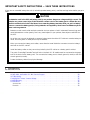 2
2
-
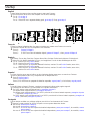 3
3
-
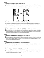 4
4
-
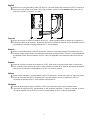 5
5
-
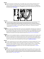 6
6
-
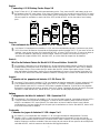 7
7
-
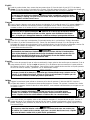 8
8
-
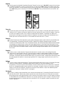 9
9
-
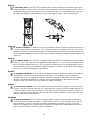 10
10
-
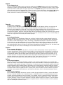 11
11
-
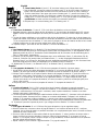 12
12
-
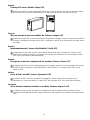 13
13
-
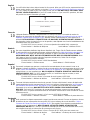 14
14
-
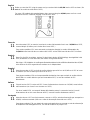 15
15
-
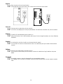 16
16
-
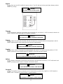 17
17
-
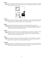 18
18
-
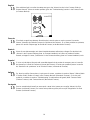 19
19
-
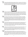 20
20
-
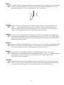 21
21
-
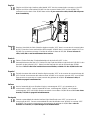 22
22
-
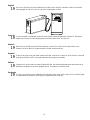 23
23
-
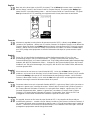 24
24
-
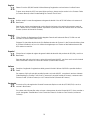 25
25
-
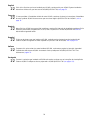 26
26
-
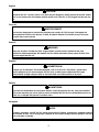 27
27
-
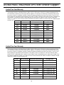 28
28
-
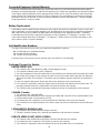 29
29
-
 30
30
-
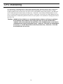 31
31
-
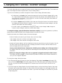 32
32
-
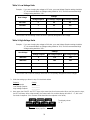 33
33
-
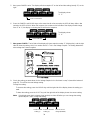 34
34
-
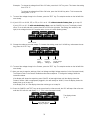 35
35
-
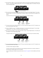 36
36
-
 37
37
-
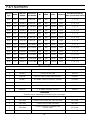 38
38


Fortress Technologies AS/400 Installation and Service Manual
- Tipo
- Installation and Service Manual
en otros idiomas
- français: Fortress Technologies AS/400
- italiano: Fortress Technologies AS/400
- English: Fortress Technologies AS/400
- Deutsch: Fortress Technologies AS/400
- português: Fortress Technologies AS/400
Otros documentos
-
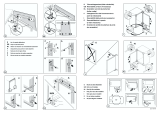 Küppersbusch EUO1120 Manual de usuario
-
AEG EUO1120 Manual de usuario
-
 Best Power Fortress 2250 VA Guía del usuario
-
NGS Fortress 900 Manual de usuario
-
 Best Power Patriot Pro II 750 VA Guía del usuario
-
Powerware 5125 P33 Guía de instalación
-
Eaton Powerware 9125 Guía de instalación
-
Riello Dialog Vision Manual de usuario
-
 Aros Syncro 1500 Manual de usuario
-
Riello DVT 80 Manual de usuario


