CAME A3000A Manual de usuario
- Categoría
- Abridor de puerta
- Tipo
- Manual de usuario

Documentazione
Tecnica
U12
rev. 1.0
07/2006
©
CAME
CANCELLI
AUTOMATICI
SCHEDA COMANDO
CONTROL BOARD
CARTE DE COMMANDE
STEUERPLATINE
TARJETA DE MANDO
Kit A3000A
ITALIANO/ ENGLISH/ ESPAÑOL
119DU12-1
SISTEMI COMPLETI ATI <|>
ATI SET COMPLETE
<|>
EQUIPOS COMPLETOS ATI
4 x 1,5
2 x 1 - TX
4 x 1
2 x 1,5
3 x 1,5
2 x 1
3 x 1
230 V
4 x 1 - RX
T
R
G
5
8
4 x 1,5
8
1
1
5
4
3
4
2
4
4
7
6
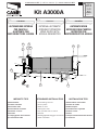
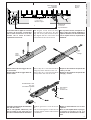
1) Motoriduttore
2) Quadro comando
3) Ricevitore radio
4) Fotocellule di sicurezza
5) Selettore a chiave
6) Antenna
7) Lampeggiatore di movimento
8) Trasmettitore radio
1) Irreversible gear motor
2) Control panel
3) Radio receiver
4) Safety photocells
5) Key-operated selector switch
6) Antenna
7) Flashing light indicating gate movement
8) Radio transmitter
1) Motorreductor irreversible
2) Cuadro de mando
3) Radiorreceptor
4) Fotocélulas de seguridad
5) Selector a llave
6) Antena
7) Lámpara intermitente de movimiento
8) Transmisor
IMPIANTO TIPO
STANDARD INSTALLATION
INSTALACION TIPO
EXTERNAL AUTOMATIC
OPENING SYSTEM FOR
WING GATES WITH
A3000A GEARMOTOR
AUTOMAZIONE ESTERNA
PER CANCELLI
A BATTENTE CON
MOTORIDUTTORE A3000A
AUTOMATIZACION
EXTERIOR PARA PUERTAS
BATIENTES CON
MOTORREDUCTOR A3000A
ITALIANO
ENGLISH
ESPAÑOL

2
ITALIANO • ENGLISH • ESPAÑOL
793
300
720
88
126
- Datos relativos a valores de la tension nominal
y a condiciones de apertura estándar.
-
* Ajustable mediante los cuadros de mando
CAME.
- Data refers to nominal power supply and standard
conditions of aperture.
-
* Can be adjusted using CAME control panels.
- Dati relativi a valori di alimentazione nominale e
condizioni di apertura standard.
-
* Regolabile mediante quadri comando CAME.
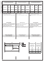
Corsa |
Travel
Recorrido
LARGHEZZA ANTA PESO ANTA
WING WIDTH WING WEIGHT
ANCHO HOJA PESO HOJA
m kg
2.00 800
2.50 600
3.00 400
DESCRIPTION:
- Designed and constructed entirely by
CAME Cancelli Automatici S.p.a
- IP54 protecting rating;
- Guaranteed for 24 months, unless tam-
pered with by unauthorized personnel.
DESCRIPCIÓN:
- Diseñado y fabricado enteramente
por CAME Cancelli Automatici S.p.a
- Grado de protección IP54;
- Garantizado 24 meses, salvo mani-
pulaciones.
DESCRIZIONE:
- Progettato e costruito interamente
dalla CAME Cancelli Automatici S.p.a.
- Grado di protezione IP 54;
- Garantito 24 mesi salvo manomissio-
ni.
Caratteristiche tecniche
Tecnichal caracteristics
Características técnicas
Misure d'ingombro
e limiti d'impiego
Overall dimensions
and use limiets
Dimensiones máximas
y limites de empleo
EROTTUDIROTOM OSEP ENOIZATNEMILA ETNERROC
ELANIMON
AZNETOP AZNETTIMRETNI
OROVAL
OTROPPAR
ENOIZUDIRID
ATNIPS OPMET
ASROC
EROTASNEDNOC
ROTOMRAEG THGIEW YLPPUSREWOP LANIMON
TNERRUC
REWOP ELCICYTUD OITARNOITCUDER HSUP LEVART
EMIT
ROTICAPAC
ROTCUDERROTOM OSEP NOICATNEMILA ETNEIRROC
LANIMON
AICNETOP AICNETIMRETNI
OJABART
NOICCALER
NOICCUDERED
EJULPME EDOPMEIT
ODIRROCER
RODASNEDNOC
A0003A gK01 .c.aV032 A2,1 W051 %05 63/1 N0003÷004* s91 Fµ01

3
ITALIANO • ENGLISH • ESPAÑOL
Tab. 3
PRIMA DI PROCEDERE ALL’INSTAL-
LAZIONE DELL’AUTOMATISMO,
CONTROLLARE:
- che la struttura del cancello sia ade-
guatamente robusta, le cerniere siano
efficienti e che non vi sia attrito tra parti
fisse e mobili;
- che la misura C non sia superiore
al valore indicato nella Tab. 3. In tal
caso è necessario intervenire sul pila-
stro in modo da raggiungere tale
misura;
- il percorso dei cavi elettrici secon-
do le disposizioni di comando e
sicurezza;
- che ci sia una battuta d'arresto
meccanico in chiusura (ben fissata al
suolo) per evitare l'oltrecorsa anta/mo-
toriduttore.
BEFORE BEGINNING INSTALLATION
OF THE AUTOMATION SYSTEM, CHECK
THE FOLLOWING:
- the structure of the gate must be suf-
ficiently strong; the hinges must function
efficiently and there must be no friction
between the moving parts and fixed parts;
- measurement C must not be greater
than the value shown in Tab. 3. If this is
the case, it is necessary to modify the pil-
lar so that this measurement
cor-responds;
- the electrical wiring path according to
the position of the control and safety
instruments;
- presence of a mechanical gate stop
(securely anchored to the ground) in the
closed position in order to prevent the gate
and the reduction gear from moving be-
yond the correct close position.
ANTES DE PROCEDER A LA INS-
TALACIÓN DEL AUTOMATISMO,
CONTROLAR:
- la estructura de la puerta sea lo su-
ficientemente sólida, las bisagras sean
eficientes y que no haya rozamiento
entre las piezas fijas y aquéllas móvi-
les;
- la medida C no sea superior al dato
indicado en la Tab.3. En tal caso, es
necesario actuar sobre el pilar hasta
alcanzar dicha medida;
- el recorrido de los cables eléctricos
según las disposiciones de mando y
seguridad;
- la existencia de un tope para el cie-
rre (bien fijado en el suelo) para evitar
que la hoja/motorreductor llegue más
allá de lo requerido.
Pilastro
Pillar
Pilar
Cerniera
Hinge
Bisagra
Anta
Leaf
Hoja
Battuta d’arresto
Gate stopper
Tope
Controlli generali
General control procedure
Controles generales
APERTURA
OPENING
ABERTURA
A
mm
B
mm
C max
mm
E
mm
90°
130
130 60
720
120° 110 50

4
ITALIANO • ENGLISH • ESPAÑOL
M8x38
M8
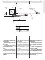
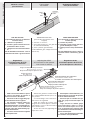
Applicare al pilastro la piastra di fis-
saggio con la staffa di coda
rispettando le quote A e B (Tab. 3) tra
l'asse della cerniera e il foro centrale
della staffa. La staffa di coda è dotata
di ulteriori forature per variare l'ango-
lo di apertura del cancello.
N.B.: aumentando la misura B diminu-
isce l'angolo di apertura con
conseguente diminuzione della veloci-
tà periferica e aumento della spinta
motore sull'anta.
Aumentando la misura A aumenta l'an-
golo di apertura con conseguente
aumento della velocità periferica e di-
minuzione della spinta motore
sull'anta.
Attach the fixing plate and the rear brack-
et to the pilar observing measurement A
and B shown in Tab. 3 pag. 3, between
the hinge pin and the central hole in the
bracket. The rear bracket is equipped with
additional holes to change the opening
angle of the gate.
N.B.: if measurement B is increased, the
opening angle is reduced. This therefore
reduces the peripheral speed and in-
creases the thrust exerted by the motor
on the gate.
I
f measurement A is increased, the angle
of aperture is increased. This therefore
increases the peripheral speed and reduc-
es the thrust exerted by the motor on the
gate.
Piastra di fissaggio
Fixing plate
Placa de fijación
Staffa di coda
Rear bracket
Soporte trasero
Boccola
Bushing
Casquillo
Snodo di coda
Rear joint
Articulacìon
trasera
Montaggio
Assembly
Montaje
Aplicar al pilar la placa de fijación me-
diante el soporte trasero respetando
las cotas A y B (Tab. 3, pag. 3) entre la
bisagra y el agujero central de sopor-
te. El soporte trasero está dotado de
otros agujeros para variar el ángulo de
apertura de la puerta.
N.B.: aumentando la medida B, se re-
duce el ángulo de apertura y por
consiguiente la velocidad periférica
mientras aumenta el empuje del mo-
tor sobre la hoja.
Aumentando la medida A, aumenta
también el ángulo de apertura y por
consiguiente la velocidad periférica
mientras se reduce el empuje del mo-
tor sobre la hoja.

5
ITALIANO • ENGLISH • ESPAÑOL
E
A cancello chiuso applicare sull'anta
la piastra di fissaggio, accertandosi
che la staffa di testa sia in asse oriz-
zontale con la staffa di coda e
rispettando la misura E.
With the gate closed, attach the fixing
plate with the front bracket to the gate
wing. The anchor plate must be horizon-
tally aligned with the rear bracket and
measurement E must be observed.
Con la puerta cerrada, incorporar a la
hoja la placa de fijación mediante el
soporte delantero, en línea horizontal
con el soporte trasero, respetando la
medida E.
Svitare le due viti di fissaggio del car-
ter ed estrarlo.
Svitare le due viti di fissaggio dello ste-
lo ed estrarlo.
Procedere al montaggio del motoridut-
tore alle due staffe.
N.B: è consigliabile lubrificare (con
grasso neutro) la vite senza fine e la
boccola al momento dell'installazione.
Piastra di fissaggio
Fixing plate
Placa de Fijación
Livellare la staffa
Level the braket
Nivelar el soporte
Staffa di testa
Front bracket
Soporte delantero
Spessore
Thickness
Espesor
Carter
Casing
Cárter
Dado M8 autobloccante
M8 locknut
Tuerca M8 de seguridad
Vite senza fine
Worm-gear
Tornillo sin fin
Stelo
Rod
Vástago
Remove thje two screws which hold the
casing in position and remove the rod.
Remove thje two screws which hold the
rod in position and remove the rod.
Aflojar los dos tornillos de fijación del
cárter y sacarlo.
Aflojar los dos tornillos de fijación del
vástago y sacarlo.
Install the gear motor on the two brack-
ets.
N.B: use neutral grease to lubricate the
wormgear and the washer at the moment
of installation.
Montar el motorreductor en los dos
soportes.
Nota: es aconsejable lubricar (con gra-
sa neutra) el tornillo sin fin y la
arandela en el momento de la instala-
ción.

6
ITALIANO • ENGLISH • ESPAÑOL
PER SBLOCCARE
(l'operazione di sblocco va effettuata
a motore fermo)
1) sollevare lo sportellino;
2) inserire e girare la chiave che istan-
taneamente sblocca l'anta;
3) spingere o tirare l'anta manualmen-
te.
Per BLOCCARE nuovamente l'anta è
sufficiente reinserire e girare la chiave
PARA DESBLOQUEAR
(esta operación se debe efectuar con
el motor parado)
1) levantar el portillo;
2) introducir y girar la llave que ense-
guida desbloquea la hoja;
3) empujar o tirar la hoja manualmen-
te.
Para BLOQUEAR de nuevo la hoja, es
suficiente volver a introducir y girar la
llave.
RELEASING THE UNIT
(perform this step with the motor
stopped)
1) raise the access door;
2) insert and turn the key. The gate will
be released immediately;
3) push or pull the gate manually.
To RE-LOCK the gate, simply insert and
turn the key.
Sportellino
Access door
Portillo
Chiave
Key
Llave
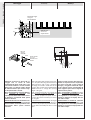
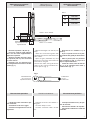
Regolazione
microinterruttori di STOP
in apertura e chiusura
- Sbloccare il motoriduttore e porta-
re l'anta in posizione di apertura o
chiusura massima desiderata.
- Svitare le viti di fissaggio del grup-
po microinterrutore da regolare.
- Far scorrere il relativo gruppo mi-
crointerruttore sull'asta porta
microinterruttore fino a raggiungere l'in-
serimento dello stesso mediante
contatto sulla slitta azionamento grup-
po microinterruttore.
- Fissare il microinterruttore agendo
sulle rispettive viti.
Slitta azionamento microinterruttori
Microswitches actuation runner
Corredera accionamiento microinterruptores
Asta porta-microinterruttori
Support plate microswitches
Chapa porta-microinterruptores
Gruppo microinterrutore di stop in chiusura
Microswitch unit for closure stop
Grupo microinterruptor de parada en cierre
Viti di fissaggio micro
Micro fixing screws
Tornillos de fijación micro
Gruppo microinterrutore di stop in apertura
Microswitch unit for opening stop
Grupo microinterruptor de parada en apertura
- Release the gearmotor and move the
door to the maximum desired open or clo-
sure position.
- Loosen the fixing screws of the micro-
switch unit to be regulated.
- Slide the related microswitch unit
along the microswitch-support rod until it
is inserted by contact on the microswitch
unit actuation runner.
- Fix the microswitch by tightening the
respective screws.
- Desbloquee el motorreductor y co-
loque la hoja en la posición de apertura
o cierre máxima deseada.
- Desenrosque los tornillos de fija-
ción del grupo microinterruptor de
regular.
- Haga deslizar el relativo grupo
microinterruptor sobre la varilla
porta-microinterruptor hasta que
este se introduzca por contacto sobre
la corredera de accionamiento del gru-
po microinterruptor.
- Fije el microinterruptor apretando
los tornillos correspondientes.
Adjusting the STOP
microswitches for the aperture
and closure movement
Regulacion de los
microinterruptores de STOP en
la fase de apertura e de cierre
Sblocco a chiave
personalizzata
Personalized
key release
Desbloqueo mediante
llave personalizada

7
ITALIANO • ENGLISH • ESPAÑOL
TAB. 4
Fig. 1
A
mm031
B
mm031
E
mm027
- Rilevare le quote A e B (Tab. 4).
- Fissare la staffa di coda integran-
dola con una staffa supplementare e
applicarla al pilastro.
- Aprire il cancello (max 90°), rileva-
re la quota E (Tab. 4) e fissare all'anta
la staffa di testa.
- Invertire i cavi, tra i morsetti U e V,
nel collegamento tra motore e conden-
satore (fig. 1).
- Measure the lenght of "A" and "B" (see
Tab 4).
- Attach the rear bracket together with
a supplementary bracket and fasten both
to the column.
- Open the gate (maximum 90°) and
measure "E" (see Tab 4), then fasten the
front bracket to the gate.
- Reverse the cables, among the bornes
U and V, in the connection between mo-
tor and capacitor (fig. 1).
- Determinar las medidas A y B
(Tab. 4).
- Fijar el soporte trasero en el pilar,
tras haberlo integrado por oltro adicio-
nal.
- Abrir la puerta (max 90°), determi-
nar la medida E (Tab. 4) y fijar en la
hoja el soporte delantero.
- Invertir los cables, entre los bornes
U y V, en la conexión entre motor y
condensador (fig. 1).
Applicazione per aperture
verso l'esterno
Morsettiera motore
Motor terminal block
Caja de bornes motor
Condensatore
Capacitor
Condensador
Esterno
- Outside-
Exterior
Interno -
Insoide
- Interior
Staffa supplementare
Supplementary bracket
Soporte adicional
Application for
outside aperture
Aplicación para apertura
hacia exterior
Manutenzione periodica
Periodic maintenance
Mantenimiento periódico
- Lubrificare la vite senza fine e i per-
ni di rotazione;
- Controllare le viti di fissaggio;
- Verificare l'integrita' dei cavi di col-
legamento.
- Lubricate the worm screw and the ro-
tating pins;
- Ceck the clamps screws;
- Ceck the connection cable's sound-
ness.
- Lubrique el tornillo sin fin y los per-
nos de rotación;
- Controle los tornillos de sujeción;
- Controle el estado de los cables de
conexión.

CAME NORD S.R.L._____________COLOGNO M. (MI)
(+39) 02 26708293 (+39) 02 25490288
CAME SUD S.R.L. ___________________NAPOLI
(+39) 081 7524455 (+39) 081 7529109
CAME (AMERICA) L.L.C.____________MIAMI ( FL)
(+1) 305 5930227 (+1) 305 5939823
CAME AUTOMATISMOS S.A__________MADRID
(+34) 091 5285009 (+34) 091 4685442
CAME BELGIUM________________LESSINES
(+32) 068 333014 (+32) 068 338019
CAME FRANCE S.A.____NANTERRE CEDEX (PARIS)
(+33) 01 46130505 (+33) 01 46130500
CAME GMBH________KORNTAL BEI (STUTTGART)
(+49) 07 11839590 (+49) 07 118395925
CAME GMBH____________SEEFELD BEI (BERLIN)
(+49) 03 33988390 (+49) 03 339885508
CAME PL SP.ZO.O______________WARSZAWA
(+48) 022 8365076 (+48) 022 8369920
CAME UNITED KINGDOM LTD___NOTTINGHAM
(+44) 01159 210430 (+44) 01159 210431
CAME CANCELLI AUTOMATICI S.P.A.
DOSSON DI CASIER (TREVISO)
(+39) 0422 4940 (+39) 0422 4941
SISTEMA QUALITÀ
CERTIFICATO
ASSISTENZA TECNICA
NUMERO VERDE
800 295830
W
EB
www.came.it
E-MAIL
Tutti i dati sono stati controllati con la massima cura. Non ci
assumiamo comunque alcuna responsabilità per eventuali errori od
omissioni.
All data checked with the maximum care. However, no liability is accepted
for any error or omission.
Todos los datos se han controlado con la máxima atención. No
obstante no nos responsabilizamos de los posibles errores u
omisiones.
DICHIARAZIONE
DEL FABBRICANTE
Ai sensi dell’Allegato II B
della Direttiva Macchine 98/37/CE
I Rappresentanti della
CAME Cancelli Automatici S.p.A.
via Martiri della Libertà, 15
31030Dosson di Casier - Treviso - ITALY
tel (+39) 0422 4940 - fax (+39) 0422 4941
internet: www.came.it - e-mail: [email protected]
Dichiarano sotto la propria responsabilità che
i/il prodotto/i denominato/i ...
… sono conformi ai requisiti essenziali ed alle
disposizioni pertinenti, stabilite dalle seguenti
Direttive e alle parti applicabili delle Normative
di riferimento in seguito elencate:
DIRETTIVA MACCHINE
98/37/CE - 98/79/CE
D
IRETTIVA BASSA TENSIONE
73/23/CEE - 93/68/CEE
D
IRETTIVA COMPATIBILITÀ ELETTROMAGNETICA
89/336/CEE - 92/31/CEE
D
IRETTIVA MATERIALI DA COSTRUZIONE
89/106/CEE
D
IRETTIVA R&TTE
1999/5/CE
NORMATIVE:
EN 13241-1, EN 12453, EN 12445, EN 12635,
EN 12978, EN 60335-1, EN 61000-6-2,
EN 61000-6-3, EN 60204-1
AVVERTENZA IMPORTANTE!
È vietato mettere in servizio il/i prodotto/i,
oggetto della presente dichiarazione, prima
del completamento e/o incorporamento, in
totale conformità alle disposizioni della
Direttiva Macchine 98/37/CE
L’Amministratore Delegato
Sig. Andrea Menuzzo
A3000A
AF43S • DIR10 • DOC-E • KIARON
S4339 • SET-E • SET-J
TOP-432NA • TOP-434NA • TOP-A433N
TOP-RG58 • ZA3 • ZA4 • ZF1
Codice di riferimento per richiedere una copia
conforme all’originale: DDF B IT A020 ver.1.0
DECLARACION DEL
FABRICANTE
De conformidad con el Anexo II B de la
Directiva de Máquinas 98/37/CE
ILos Representantes de la compañía
CAME Cancelli Automatici S.p.A.
via Martiri della Libertà, 15
31030Dosson di Casier - Treviso - ITALYtel
(+39) 0422 4940 - fax (+39) 0422 4941
internet: www.came.it - e-mail: [email protected]
Declaran bajo su responsabilidad que el/los
producto/s denominado/s ...
… son de conformidad con los requisitos
esenciales y las disposiciones pertinentes,
establecidos por las siguientes Directivas y
con las partes aplicables de las Normativas de
referencia que se indican a continuación:
DIRECTIVA DE MÁQUINAS
98/37/CE - 98/79/CE
D
IRECTIVA DE BAJA TENSIÓN
73/23/CEE - 93/68/CEE
D
IRECTIVA DE COMPATIBILIDAD ELECTROMAGNÉTICA
89/336/CEE - 92/31/CEE
D
IRECTIVA MATERIALES PARA LA FABRICACIÓN
89/106/CEE
D
IRECTIVA R&TTE
1999/5/CE
NORMATIVAS:
EN 13241-1, EN 12453, EN 12445, EN 12635,
EN 12978, EN 60335-1, EN 61000-6-2,
EN 61000-6-3, EN 60204-1
ADVERTENCIA IMPORTANTE!
Está prohibido hacer uso de el/los producto/s,
objeto de la presente declaración antes de
completarlo/s y/o incorporarlo/s en total
conformidad a las disposiciones de la
Directiva de Máquinas 98/37/CE.
el Administrador Delegado
Sig. Andrea Menuzzo
Código de referencia para solicitar una copia de con-
formidad con la copia original: DDF B ES A020 ver.1.0
MANUFACTURER’S
DECLARATION
As per Enclosure II B of
Machinery Directive 98/37/CE
The representatives of
CAME Cancelli Automatici S.p.A.
via Martiri della Libertà, 15
31030Dosson di Casier - Treviso - ITALYtel
(+39) 0422 4940 - fax (+39) 0422 4941
internet: www.came.it - e-mail: [email protected]
Hereby declare, under their own respons
ibility, that the product/s called ...
… comply with the National Law related to the
following European Directives and to the
applicable parts of the following Standards:
MACHINERY DIRECTIVE
98/37/CE - 98/79/CE
L
OW VOLTAGE DIRECTIVE
73/23/EEC - 93/68/EEC
L
ECTROMAGNETIC COMPATIBILITY DIRECTIVE
89/336/EEC - 92/31/EEC
C
ONSTRUCTION PRODUCTSS DIRECTIVE
89/106/CE
R&TTE D
IRECTIVE
1999/5/CE
STANDARDS:
EN 13241-1, EN 12453, EN 12445,EN 12635,
EN 12978, EN 60335-1, EN 61000-6-2,
EN 61000-6-3, EN 60204-1
IMPORTANT CAUTION!
It is forbidden to market/use product/s that are
the subject of this declaration before
completing and/or incorporating them in total
compliance with the provisions of Machinery
Directive 98/37/CE
the Managing Director
Mr. Andrea Menuzzo
Reference code to request a true copy
of the original: DDF B EN A020 ver.1.0
A3000A
AF43S • DIR10 • DOC-E • KIARON
S4339 • SET-E • SET-J
TOP-432NA • TOP-434NA • TOP-A433N
TOP-RG58 • ZA3 • ZA4 • ZF1
A3000A
AF43S • DIR10 • DOC-E • KIARON
S4339 • SET-E • SET-J
TOP-432NA • TOP-434NA • TOP-A433N
TOP-RG58 • ZA3 • ZA4 • ZF1
Transcripción de documentos
ATI <|> ATI SET COMPLETE <|> EQUIPOS COMPLETOS ATI I TA L I A N O / E N G L I S H / E S PA Ñ O L SISTEMI COMPLETI SCHEDA COMANDO CONTROL BOARD CARTE DE COMMANDE STEUERPLATINE TARJETA DE MANDO Kit A3000A Documentazione Tecnica U12 rev. 1.0 07/2006 © CAME CANCELLI AUTOMATICI 119DU12-1 ITALIANO ENGLISH ESPAÑOL AUTOMAZIONE ESTERNA PER CANCELLI A BATTENTE CON MOTORIDUTTORE A3000A EXTERNAL AUTOMATIC OPENING SYSTEM FOR WING GATES WITH A3000A GEARMOTOR AUTOMATIZACION EXTERIOR PARA PUERTAS BATIENTES CON MOTORREDUCTOR A3000A 6 3 4 7 4 T RG58 2 5 230 V 3 x 1,5 3x1 2 x 1,5 4x1 2x1 4 4 x 1,5 4 x 1,5 4 x 1 - RX 4 8 IMPIANTO TIPO 1) Motoriduttore 2) Quadro comando 3) Ricevitore radio 4) Fotocellule di sicurezza 5) Selettore a chiave 6) Antenna 7) Lampeggiatore di movimento 8) Trasmettitore radio 2 x 1 - TX 1 STANDARD INSTALLATION 1) Irreversible gear motor 2) Control panel 3) Radio receiver 4) Safety photocells 5) Key-operated selector switch 6) Antenna 7) Flashing light indicating gate movement 8) Radio transmitter 1 INSTALACION TIPO 1) Motorreductor irreversible 2) Cuadro de mando 3) Radiorreceptor 4) Fotocélulas de seguridad 5) Selector a llave 6) Antena 7) Lámpara intermitente de movimiento 8) Transmisor ESPAÑOL • ENGLISH MOTORIDUTTORE GEARMOTOR PESO Características técnicas ALIMENTAZIONE CORRENTE NOMINALE POTENZA INTERMITTENZA LAVORO RAPPORTO DI RIDUZIONE SPINTA TEMPO CORSA CONDENSATORE WEIGHT POWER SUPPLY NOMINAL CURRENT POWER DUTY CICLE REDUCTION RATIO PUSH TRAVEL TIME CAPACITOR MOTORREDUCTOR PESO ALIMENTACION CORRIENTE NOMINAL POTENCIA INTERMITENCIA TRABAJO RELACCION DE REDUCCION EMPLUJE TIEMPO DE RECORRIDO CONDENSADOR A 3000A 10 Kg 230V a.c. 1,2 A 150 W 50 % 1/36 *400÷3000N 19 s 10 µF ITALIANO • Tecnichal caracteristics Caratteristiche tecniche - Dati relativi a valori di alimentazione nominale e condizioni di apertura standard. - Data refers to nominal power supply and standard conditions of aperture. - Datos relativos a valores de la tension nominal y a condiciones de apertura estándar. - * Regolabile mediante quadri comando CAME. - * Can be adjusted using CAME control panels. - * Ajustable mediante los cuadros de mando CAME. - Garantito 24 mesi salvo manomissioni. DESCRIPTION: - Designed and constructed entirely by CAME Cancelli Automatici S.p.a - IP54 protecting rating; - Guaranteed for 24 months, unless tampered with by unauthorized personnel. Misure d'ingombro e limiti d'impiego Overall dimensions and use limiets DESCRIZIONE: - Progettato e costruito interamente dalla CAME Cancelli Automatici S.p.a. - Grado di protezione IP 54; 126 Corsa | Travel Recorrido 300 2 - Grado de protección IP54; - Garantizado 24 meses, salvo manipulaciones. Dimensiones máximas y limites de empleo 88 793 720 DESCRIPCIÓN: - Diseñado y fabricado enteramente por CAME Cancelli Automatici S.p.a LARGHEZZA ANTA PESO ANTA WING WIDTH WING WEIGHT ANCHO HOJA PESO HOJA m kg 2.00 800 2.50 600 3.00 400 Controles generales Cerniera Hinge Bisagra Battuta d’arresto Gate stopper Tope ITALIANO Pilastro Pillar Pilar • ENGLISH • ESPAÑOL General control procedure Controlli generali Anta Leaf Hoja Tab. 3 APERTURA OPENING ABERTURA 90° 120° PRIMA DI PROCEDERE ALL’INSTALLAZIONE DELL’AUTOMATISMO, CONTROLLARE: - che la struttura del cancello sia adeguatamente robusta, le cerniere siano efficienti e che non vi sia attrito tra parti fisse e mobili; - che la misura C non sia superiore al valore indicato nella Tab. 3. In tal caso è necessario intervenire sul pilastro in modo da raggiungere tale misura; - il percorso dei cavi elettrici secondo le disposizioni di comando e sicurezza; - che ci sia una battuta d'arresto meccanico in chiusura (ben fissata al suolo) per evitare l'oltrecorsa anta/motoriduttore. A mm 130 B mm C max mm 130 60 110 50 E mm 720 BEFORE BEGINNING INSTALLATION OF THE AUTOMATION SYSTEM, CHECK THE FOLLOWING: - the structure of the gate must be sufficiently strong; the hinges must function efficiently and there must be no friction between the moving parts and fixed parts; - measurement C must not be greater than the value shown in Tab. 3. If this is the case, it is necessary to modify the pillar so that this measurement cor-responds; - the electrical wiring path according to the position of the control and safety instruments; - presence of a mechanical gate stop (securely anchored to the ground) in the closed position in order to prevent the gate and the reduction gear from moving beyond the correct close position. ANTES DE PROCEDER A LA INSTALACIÓN DEL AUTOMATISMO, CONTROLAR: - la estructura de la puerta sea lo suficientemente sólida, las bisagras sean eficientes y que no haya rozamiento entre las piezas fijas y aquéllas móviles; - la medida C no sea superior al dato indicado en la Tab.3. En tal caso, es necesario actuar sobre el pilar hasta alcanzar dicha medida; - el recorrido de los cables eléctricos según las disposiciones de mando y seguridad; - la existencia de un tope para el cierre (bien fijado en el suelo) para evitar que la hoja/motorreductor llegue más allá de lo requerido. 3 Assembly Montaje ENGLISH • ESPAÑOL Montaggio ITALIANO • Piastra di fissaggio Fixing plate Placa de fijación Staffa di coda Rear bracket Soporte trasero Boccola Bushing Casquillo M8x38 Snodo di coda Rear joint Articulacìon trasera M8 Applicare al pilastro la piastra di fissaggio con la staffa di coda rispettando le quote A e B (Tab. 3) tra l'asse della cerniera e il foro centrale della staffa. La staffa di coda è dotata di ulteriori forature per variare l'angolo di apertura del cancello. N.B.: aumentando la misura B diminuisce l'angolo di apertura con conseguente diminuzione della velocità periferica e aumento della spinta motore sull'anta. Aumentando la misura A aumenta l'angolo di apertura con conseguente aumento della velocità periferica e diminuzione della spinta motore sull'anta. 4 Attach the fixing plate and the rear bracket to the pilar observing measurement A and B shown in Tab. 3 pag. 3, between the hinge pin and the central hole in the bracket. The rear bracket is equipped with additional holes to change the opening angle of the gate. N.B.: if measurement B is increased, the opening angle is reduced. This therefore reduces the peripheral speed and increases the thrust exerted by the motor on the gate. If measurement A is increased, the angle of aperture is increased. This therefore increases the peripheral speed and reduces the thrust exerted by the motor on the gate. Aplicar al pilar la placa de fijación mediante el soporte trasero respetando las cotas A y B (Tab. 3, pag. 3) entre la bisagra y el agujero central de soporte. El soporte trasero está dotado de otros agujeros para variar el ángulo de apertura de la puerta. N.B.: aumentando la medida B, se reduce el ángulo de apertura y por consiguiente la velocidad periférica mientras aumenta el empuje del motor sobre la hoja. Aumentando la medida A, aumenta también el ángulo de apertura y por consiguiente la velocidad periférica mientras se reduce el empuje del motor sobre la hoja. ESPAÑOL Spessore Thickness Espesor • ENGLISH • Piastra di fissaggio Fixing plate Placa de Fijación E A cancello chiuso applicare sull'anta la piastra di fissaggio, accertandosi che la staffa di testa sia in asse orizzontale con la staffa di coda e rispettando la misura E. With the gate closed, attach the fixing plate with the front bracket to the gate wing. The anchor plate must be horizontally aligned with the rear bracket and measurement E must be observed. ITALIANO Livellare la staffa Level the braket Nivelar el soporte Staffa di testa Front bracket Soporte delantero Con la puerta cerrada, incorporar a la hoja la placa de fijación mediante el soporte delantero, en línea horizontal con el soporte trasero, respetando la medida E. Stelo Rod Vástago Carter Casing Cárter Svitare le due viti di fissaggio del carter ed estrarlo. Svitare le due viti di fissaggio dello stelo ed estrarlo. Remove thje two screws which hold the casing in position and remove the rod. Remove thje two screws which hold the rod in position and remove the rod. Aflojar los dos tornillos de fijación del cárter y sacarlo. Aflojar los dos tornillos de fijación del vástago y sacarlo. Dado M8 autobloccante M8 locknut Tuerca M8 de seguridad Vite senza fine Worm-gear Tornillo sin fin Procedere al montaggio del motoriduttore alle due staffe. N.B: è consigliabile lubrificare (con grasso neutro) la vite senza fine e la boccola al momento dell'installazione. Install the gear motor on the two brackets. N.B: use neutral grease to lubricate the wormgear and the washer at the moment of installation. Montar el motorreductor en los dos soportes. Nota: es aconsejable lubricar (con grasa neutra) el tornillo sin fin y la arandela en el momento de la instalación. 5 Personalized key release Desbloqueo mediante llave personalizada ENGLISH • ESPAÑOL Sblocco a chiave personalizzata Sportellino Access door Portillo ITALIANO • Chiave Key Llave PER SBLOCCARE (l'operazione di sblocco va effettuata a motore fermo) 1) sollevare lo sportellino; 2) inserire e girare la chiave che istantaneamente sblocca l'anta; 3) spingere o tirare l'anta manualmente. Per BLOCCARE nuovamente l'anta è sufficiente reinserire e girare la chiave RELEASING THE UNIT (perform this step with the motor stopped) 1) raise the access door; 2) insert and turn the key. The gate will be released immediately; 3) push or pull the gate manually. To RE-LOCK the gate, simply insert and turn the key. Regolazione microinterruttori di STOP in apertura e chiusura Adjusting the STOP microswitches for the aperture and closure movement PARA DESBLOQUEAR (esta operación se debe efectuar con el motor parado) 1) levantar el portillo; 2) introducir y girar la llave que enseguida desbloquea la hoja; 3) empujar o tirar la hoja manualmente. Para BLOQUEAR de nuevo la hoja, es suficiente volver a introducir y girar la llave. Regulacion de los microinterruptores de STOP en la fase de apertura e de cierre Gruppo microinterrutore di stop in chiusura Microswitch unit for closure stop Grupo microinterruptor de parada en cierre Viti di fissaggio micro Micro fixing screws Tornillos de fijación micro Slitta azionamento microinterruttori Microswitches actuation runner Corredera accionamiento microinterruptores Asta porta-microinterruttori Support plate microswitches Chapa porta-microinterruptores Gruppo microinterrutore di stop in apertura Microswitch unit for opening stop Grupo microinterruptor de parada en apertura - Sbloccare il motoriduttore e portare l'anta in posizione di apertura o chiusura massima desiderata. - Svitare le viti di fissaggio del gruppo microinterrutore da regolare. - Far scorrere il relativo gruppo microinterruttore sull'asta porta microinterruttore fino a raggiungere l'inserimento dello stesso mediante contatto sulla slitta azionamento gruppo microinterruttore. - Fissare il microinterruttore agendo sulle rispettive viti. 6 - Release the gearmotor and move the door to the maximum desired open or closure position. - Loosen the fixing screws of the microswitch unit to be regulated. - Slide the related microswitch unit along the microswitch-support rod until it is inserted by contact on the microswitch unit actuation runner. - Fix the microswitch by tightening the respective screws. - Desbloquee el motorreductor y coloque la hoja en la posición de apertura o cierre máxima deseada. - Desenrosque los tornillos de fijación del grupo microinterruptor de regular. - Haga deslizar el relativo grupo microinterruptor sobre la varilla porta-microinterruptor hasta que este se introduzca por contacto sobre la corredera de accionamiento del grupo microinterruptor. - Fije el microinterruptor apretando los tornillos correspondientes. Application for outside aperture ESPAÑOL Aplicación para apertura hacia exterior ENGLISH • Applicazione per aperture verso l'esterno TAB. 4 130 mm B 130 mm E 720 mm ITALIANO • A Esterno - Outside- Exterior Staffa supplementare Supplementary bracket Soporte adicional - Rilevare le quote A e B (Tab. 4). - Fissare la staffa di coda integrandola con una staffa supplementare e applicarla al pilastro. - Aprire il cancello (max 90°), rilevare la quota E (Tab. 4) e fissare all'anta la staffa di testa. - Invertire i cavi, tra i morsetti U e V, nel collegamento tra motore e condensatore (fig. 1). Interno - Insoide - Interior - Measure the lenght of "A" and "B" (see Tab 4). - Attach the rear bracket together with a supplementary bracket and fasten both to the column. - Open the gate (maximum 90°) and measure "E" (see Tab 4), then fasten the front bracket to the gate. - Reverse the cables, among the bornes U and V, in the connection between motor and capacitor (fig. 1). - Determinar las medidas A y B (Tab. 4). - Fijar el soporte trasero en el pilar, tras haberlo integrado por oltro adicional. - Abrir la puerta (max 90°), determinar la medida E (Tab. 4) y fijar en la hoja el soporte delantero. - Invertir los cables, entre los bornes U y V, en la conexión entre motor y condensador (fig. 1). Fig. 1 Morsettiera motore Motor terminal block Caja de bornes motor Condensatore Capacitor Condensador Manutenzione periodica Periodic maintenance Mantenimiento periódico - Lubrificare la vite senza fine e i perni di rotazione; - Lubricate the worm screw and the rotating pins; - Ceck the clamps screws; - Ceck the connection cable's soundness. - Lubrique el tornillo sin fin y los pernos de rotación; - Controllare le viti di fissaggio; - Verificare l'integrita' dei cavi di collegamento. - Controle los tornillos de sujeción; - Controle el estado de los cables de conexión. 7 DICHIARAZIONE DEL FABBRICANTE MANUFACTURER’S DECLARATION DECLARACION DEL FABRICANTE Ai sensi dell’Allegato II B della Direttiva Macchine 98/37/CE As per Enclosure II B of Machinery Directive 98/37/CE De conformidad con el Anexo II B de la Directiva de Máquinas 98/37/CE I Rappresentanti della The representatives of ILos Representantes de la compañía CAME Cancelli Automatici S.p.A. via Martiri della Libertà, 15 31030Dosson di Casier - Treviso - ITALY tel (+39) 0422 4940 - fax (+39) 0422 4941 internet: www.came.it - e-mail: [email protected] CAME Cancelli Automatici S.p.A. via Martiri della Libertà, 15 31030Dosson di Casier - Treviso - ITALYtel (+39) 0422 4940 - fax (+39) 0422 4941 internet: www.came.it - e-mail: [email protected] CAME Cancelli Automatici S.p.A. via Martiri della Libertà, 15 31030Dosson di Casier - Treviso - ITALYtel (+39) 0422 4940 - fax (+39) 0422 4941 internet: www.came.it - e-mail: [email protected] Dichiarano sotto la propria responsabilità che i/il prodotto/i denominato/i ... Hereby declare, under their own respons ibility, that the product/s called ... Declaran bajo su responsabilidad que el/los producto/s denominado/s ... A3000A A3000A A3000A AF43S • DIR10 • DOC-E • KIARON S4339 • SET-E • SET-J TOP-432NA • TOP-434NA • TOP-A433N TOP-RG58 • ZA3 • ZA4 • ZF1 AF43S • DIR10 • DOC-E • KIARON S4339 • SET-E • SET-J TOP-432NA • TOP-434NA • TOP-A433N TOP-RG58 • ZA3 • ZA4 • ZF1 AF43S • DIR10 • DOC-E • KIARON S4339 • SET-E • SET-J TOP-432NA • TOP-434NA • TOP-A433N TOP-RG58 • ZA3 • ZA4 • ZF1 … sono conformi ai requisiti essenziali ed alle disposizioni pertinenti, stabilite dalle seguenti Direttive e alle parti applicabili delle Normative di riferimento in seguito elencate: … comply with the National Law related to the following European Directives and to the applicable parts of the following Standards: … son de conformidad con los requisitos esenciales y las disposiciones pertinentes, establecidos por las siguientes Directivas y con las partes aplicables de las Normativas de referencia que se indican a continuación: DIRETTIVA MACCHINE 98/37/CE - 98/79/CE MACHINERY DIRECTIVE 98/37/CE - 98/79/CE DIRECTIVA DE MÁQUINAS 98/37/CE - 98/79/CE DIRETTIVA BASSA TENSIONE 73/23/CEE - 93/68/CEE LOW VOLTAGE DIRECTIVE 73/23/EEC - 93/68/EEC DIRECTIVA DE BAJA TENSIÓN 73/23/CEE - 93/68/CEE DIRETTIVA COMPATIBILITÀ ELETTROMAGNETICA 89/336/CEE - 92/31/CEE LECTROMAGNETIC COMPATIBILITY DIRECTIVE 89/336/EEC - 92/31/EEC DIRECTIVA DE COMPATIBILIDAD ELECTROMAGNÉTICA 89/336/CEE - 92/31/CEE DIRETTIVA MATERIALI DA COSTRUZIONE 89/106/CEE CONSTRUCTION PRODUCTSS DIRECTIVE 89/106/CE DIRECTIVA MATERIALES PARA LA FABRICACIÓN 89/106/CEE DIRETTIVA R&TTE 1999/5/CE R&TTE DIRECTIVE 1999/5/CE DIRECTIVA R&TTE 1999/5/CE NORMATIVE: EN 13241-1, EN 12453, EN 12445, EN 12635, EN 12978, EN 60335-1, EN 61000-6-2, EN 61000-6-3, EN 60204-1 STANDARDS: EN 13241-1, EN 12453, EN 12445,EN 12635, EN 12978, EN 60335-1, EN 61000-6-2, EN 61000-6-3, EN 60204-1 NORMATIVAS: EN 13241-1, EN 12453, EN 12445, EN 12635, EN 12978, EN 60335-1, EN 61000-6-2, EN 61000-6-3, EN 60204-1 AVVERTENZA IMPORTANTE! È vietato mettere in servizio il/i prodotto/i, oggetto della presente dichiarazione, prima del completamento e/o incorporamento, in totale conformità alle disposizioni della Direttiva Macchine 98/37/CE IMPORTANT CAUTION! It is forbidden to market/use product/s that are the subject of this declaration before completing and/or incorporating them in total compliance with the provisions of Machinery Directive 98/37/CE ADVERTENCIA IMPORTANTE! Está prohibido hacer uso de el/los producto/s, objeto de la presente declaración antes de completarlo/s y/o incorporarlo/s en total conformidad a las disposiciones de la Directiva de Máquinas 98/37/CE. L’Amministratore Delegato Sig. Andrea Menuzzo the Managing Director Mr. Andrea Menuzzo el Administrador Delegado Sig. Andrea Menuzzo Codice di riferimento per richiedere una copia conforme all’originale: DDF B IT A020 ver.1.0 Reference code to request a true copy of the original: DDF B EN A020 ver.1.0 Código de referencia para solicitar una copia de conformidad con la copia original: DDF B ES A020 ver.1.0 Tutti i dati sono stati controllati con la massima cura. Non ci assumiamo comunque alcuna responsabilità per eventuali errori od omissioni. All data checked with the maximum care. However, no liability is accepted for any error or omission. Todos los datos se han controlado con la máxima atención. No obstante no nos responsabilizamos de los posibles errores u omisiones. ASSISTENZA TECNICA NUMERO VERDE 800 295830 SISTEMA QUALITÀ CERTIFICATO WEB www.came.it E-MAIL [email protected] CAME CANCELLI AUTOMATICI S.P.A. DOSSON DI CASIER (TREVISO) (+39) 0422 4940 (+39) 0422 4941 CAME NORD S.R.L._____________COLOGNO M. (MI) (+39) 02 26708293 (+39) 02 25490288 CAME SUD S.R.L. ___________________NAPOLI (+39) 081 7524455 (+39) 081 7529109 CAME (AMERICA) L.L.C.____________MIAMI (FL) (+1) 305 5930227 (+1) 305 5939823 CAME AUTOMATISMOS S.A__________MADRID (+34) 091 5285009 (+34) 091 4685442 CAME BELGIUM________________LESSINES (+32) 068 333014 (+32) 068 338019 CAME FRANCE S.A.____NANTERRE CEDEX (PARIS) (+33) 01 46130505 (+33) 01 46130500 CAME GMBH________KORNTAL BEI (STUTTGART) (+49) 07 11839590 (+49) 07 118395925 CAME GMBH____________SEEFELD BEI (BERLIN) (+49) 03 33988390 (+49) 03 339885508 CAME PL SP.ZO.O______________WARSZAWA (+48) 022 8365076 (+48) 022 8369920 CAME UNITED KINGDOM LTD___NOTTINGHAM (+44) 01159 210430 (+44) 01159 210431-
 1
1
-
 2
2
-
 3
3
-
 4
4
-
 5
5
-
 6
6
-
 7
7
-
 8
8


CAME A3000A Manual de usuario
- Categoría
- Abridor de puerta
- Tipo
- Manual de usuario
En otros idiomas
- italiano: CAME A3000A Manuale utente
- English: CAME A3000A User manual
Documentos relacionados
-
CAME ATI A3000 El manual del propietario
-
-
CAME FROG A24 Manual de usuario
-
-
-
-
-
CAME EMEGA Standard Installation
-
-