2 - 7IT Libretto di istruzioni pag.
8 - 13GB Instructions manual pages
14 - 19FR Notice d’instructions page
20 - 25DE Montageanleitung Seite
26 - 31ES Manual de instrucciones pàg.
COMBI 787
Automazione oleodinamica interrata per cancelli a battente
Oil-hydraulic underground operator for swinging gates
Automation hydraulique enterrée pour portails à battant
Ölhydraulischer Unterur-Antrieb für Drehtore
Automatización hidráulica enterrada para puertas batientes
EN 13241
EN 12453
EN 12445

Italiano
2
AVVERTENZE GENERALI PER LA SICUREZZA DELLE PERSONE
Grazie
Vi ringraziamo per aver deciso di acquistare un prodotto Fadini.
Vi invitiamo a leggere attentamente queste istruzioni prima di iniziare
a usare il dispositivo. Le istruzioni contengono informazioni
importanti che vi aiuteranno a trarre il meglio da questo dispositivo e
vi garantiranno altresì sicurezza in fase di installazione, uso e
manutenzione del dispositivo.
Conservare questo manuale in un luogo pratico, in modo da poterlo
sempre consultare e garantire un utilizzo sicuro e adeguato del
dispositivo.
INTRODUZIONE
Questa automazione è stata progettata per un utilizzo esclusivo per
quanto indicato in questo libretto, con gli accessori di sicurezza e di
segnalazione minimi richiesti e con i dispositivi Fadini. □ Qualsiasi altra
applicazione non espressamente indicata in questo libretto potrebbe
provocare disservizi o danni a cose e persone. □ Meccanica Fadini S.r.l.
non è responsabile per eventuali danni derivati da usi impropri e non
specicatamente indicati in questo libretto; non risponde inoltre di
malfunzionamenti derivati dall'uso di materiali e/o accessori non
indicati dalla ditta stessa. □ La ditta costruttrice si riserva di apportare
modiche ai propri prodotti senza preavviso. □ Tutto quanto non
espressamente indicato in questo manuale di istruzioni non è
permesso.
PRIMA DELL'INSTALLAZIONE
Prima di qualsiasi intervento valutare l'idoneità dell'ingresso da
automatizzare, nonché la sua condizione e la struttura. □ Accertarsi
che non si verichino situazioni di impatto, schiacciamento,
cesoiamento, convogliamento, taglio, uncinamento e sollevamento,
tali da poter pregiudicare la sicurezza delle persone. □ Non installare il
prodotto nelle vicinanze di fonti di calore ed evitare il contatto con
sostanze inammabili. □ Tenere lontano dalla portata di bambini
qualsiasi dispositivo (trasmettitori, lettori di prossimità, selettori, ecc.)
atto ad avviare l'automazione. □ Il transito nella zona di luce di
passaggio deve avvenire unicamente con l'automazione ferma. □ Non
consentire a bambini e/o persone di stazionare nei pressi
dell'impianto con l'automazione in movimento. □ Per garantire un
livello adeguato di sicurezza dell'impianto è necessario utilizzare
fotocellule, bordi sensibili, spire magnetiche e sensori di presenza per
mettere in sicurezza l'intera area interessata al movimento del
cancello. □ Servirsi di strisce giallo-nere o di adeguati segnali per
identicare i punti pericolosi dell'installazione. □ Togliere sempre
l'alimentazione elettrica all'impianto se si eettuano interventi di
manutenzione e/o pulizia. □ In caso di asportazione dell’attuatore,
non tagliare i li elettrici, ma toglierli dalla morsettiera allentando le
viti di serraggio dentro la scatola di derivazione.
INSTALLAZIONE
L'intera installazione deve essere eettuata da personale tecnico
qualicato, in osservanza della Direttiva Macchine 2006/42/CE e in
particolare le norme EN 12445 ed EN 12453. □ Vericare la presenza, a
monte dell'impianto, di un interruttore di linea 230 V - 50 Hz
magneto-termico dierenziale da 0,03 A. □ Utilizzare corpi di prova
idonei per le prove di funzionamento nella rilevazione della presenza,
in prossimità o interposti, ai dispositivi di sicurezza come fotocellule,
bordi sensibili, ecc.
□ Eseguire una attenta analisi dei rischi, utilizzando appositi strumenti
di rilevazione di impatto e schiacciamento del bordo principale di
apertura e chiusura, secondo quanto indicato nella normativa EN
12445. □ Individuare la soluzione più indicata per eliminare o ridurre
tali rischi. □ Nel caso in cui il cancello da automatizzare fosse dotato di
un ingresso pedonale, è opportuno predisporre l'impianto in maniera
tale da interdire il funzionamento del motore quando l'ingresso
pedonale è utilizzato.
□ Fornire indicazioni sulla presenza dell'impianto realizzato con
l'applicazione di targhe segnaletiche con marcatura CE sul cancello. □
L'installatore è tenuto ad informare ed istruire l'utilizzatore nale circa
l'uso corretto dell'impianto; ciò avviene rilasciandogli una
documentazione rmata denita fascicolo tecnico, comprensiva di:
schema e componenti dell'impianto, analisi dei rischi, verica degli
accessori di sicurezza, verica delle forze di impatto e segnalazione
dei rischi residui.
INDICAZIONI PER L'UTILIZZATORE FINALE
L'utilizzatore nale è tenuto a prendere visione e ricevere informazioni
unicamente per quanto concerne il funzionamento dell'impianto e
diviene lui stesso responsabile del corretto uso. □ Deve stipulare un
contratto di manutenzione ordinaria e straordinaria (su chiamata) con
l'installatore/manutentore. □ Qualsiasi intervento di riparazione deve
essere eettuato solo da personale tecnico qualicato. □ Conservare
sempre il presente manuale di istruzioni.
AVVERTENZE PER IL BUON FUNZIONAMENTO DELL'IMPIANTO
Per una resa ottimale dell’impianto nel tempo e secondo le normative
di sicurezza, è necessario eseguire una corretta manutenzione e un
adeguato monitoraggio dell’intera installazione per l’automazione,
per le apparecchiature elettroniche installate e anche per i cablaggi
ad esse eettuate. □ Tutta l’installazione deve essere eseguita da
personale tecnico qualicato, compilando il documento di verica e
collaudo ed il registro di manutenzione indicato nel libretto
normative di sicurezza (da richiedere o scaricare dal sito
www.fadini.net/supporto/downloads). □ Per l'automazione è
consigliato un controllo di manutenzione almeno ogni 6 mesi, mentre
per apparecchiature elettroniche e sistemi di sicurezza un controllo
mensile di manutenzione. □ Meccanica Fadini S.r.l. non è responsabile
dell'eventuale inosservanza della buona tecnica di installazione e/o
del non corretto mantenimento dell'impianto.
SMALTIMENTO DEI MATERIALI
Gli involucri dell’imballo come cartone, nylon, polistirolo, ecc.
possono essere smaltiti eettuando la raccolta dierenziata (previa
verica delle normative vigenti nel luogo dell'installazione in materia
di smaltimento riuti). Elementi elettrici, elettronici e batterie
possono contenere sostanze inquinanti: rimuovere e adare tali
componenti a ditte specializzate nel recupero dei riuti, come
indicato nella direttiva 2012/19/UE. Vietato gettare nei riuti materiali
nocivi per l’ambiente.
Meccanica Fadini S.r.l.
Direttore Responsabile
DICHIARAZIONE DI CONFORMITÀ CE del costruttore:
Meccanica Fadini S.r.l. (Via Mantova, 177/A - 37053 Cerea - VR - Italy) dichiara sotto la propria responsabilità che COMBI 787 è
conforme alla direttiva macchine 2006/42/CE, inoltre: viene commercializzato per essere installato come "impianto
automatizzato", con accessori e componenti originali indicati dalla Ditta Costruttrice. L'automazione, secondo i termini di legge,
è una "macchina" e pertanto devono essere applicate dall'Installatore tutte le norme di sicurezza. L'installatore stesso è tenuto a
rilasciare la propria Dichiarazione di Conformità. La ditta costruttrice non si assume responsabilità circa l'uso improprio del
prodotto. Il prodotto risulta conforme alle seguenti normative speciche: Analisi dei Rischi e successivo intervento per eliminarli
EN 12445 ed EN 12453, Direttiva Bassa Tensione 2014/35/UE, Direttiva Compatibilità Elettromagnetica 2014/30/UE. Al ne di
certicare il prodotto il Costruttore dichiara sotto la propria responsabilità il rispetto della NORMATIVA DI PRODOTTO
EN 13241-1.
Automazione oleodinamica interrata
per cancelli a battente
COMBI 787

Italiano
3
ANTA SINISTRA
ANTA DESTRA
!
!
!
IMPORTANTE: È PREFERIBILE USARE SEMPRE LE BATTUTE DI APERTURA E DI CHIUSURA A TERRA.
IN MANCANZA DI ESSE, COMBI 787 È PREDISPOSTO PER L’INSTALLAZIONE DELLE BATTUTE ALL'INTERNO
DELLA CASSA DI FONDAZIONE.
SALDATURA DELL'ANTA SULLA PIASTRA DELLO SBLOCCO
Appoggiare l'anta sopra la piastra dello sblocco, allineando entrambi in asse, rispettando i segni di riferimento e
mettendo in bolla con la cerniera superiore.
!
Grasso
1
Automazione oleodinamica interrata
per cancelli a battente
COMBI 787

Italiano
4
ANTA SINISTRA
COMBI 787
SULL'ANTA SINISTRA
ANTA SINISTRA
30 - 40° 30 - 40°
ANTA DESTRA
COMBI 787
SULL'ANTA DESTRA
ANTA DESTRA
Combi 787 Combi 787
INSTALLARE COMBI 787 DENTRO LE CASSE DI FONDAZIONE
Inserire e ssare con i 4 prigionieri Combi 787 all'interno delle casse di fondazione: non c'è distinzione tra Combi 787
destro e Combi 787 sinistro.
Stringere bene a fondo i 4 prigionieri esagonali.
2
INSTALLARE I BRACCI DI MOVIMENTO SULL'ALBERO QUADRO
3ATTENZIONE: INSERIRE IL BRACCIO DI MOVIMENTO AVENDO ACCURATEZZA DI ALLINEARE LA TACCA
SEGNATA SULL'ALBERO QUADRO CON LA RISPETTIVA TACCA SUL BRACCIO DI MOVIMENTO:
- COMBI 787 INSTALLATO A DESTRA: ALLINEARE LA TACCA SEGNATA DX
- COMBI 787 INSTALLATO A SINISTRA: ALLINEARE LA TACCA SEGNATA SX
Ruotare l'albero di 30-40° circa in direzione opposta all'apertura dell'anta (verso l'esterno): manualmente (sbloccando Combi 787),
oppure elettricamente (con alimentazione provvisoria).
Sblocco idraulico: girare
la leva per le manovre
manuali, poi ribloccare.
!
Automazione oleodinamica interrata
per cancelli a battente
COMBI 787

Italiano
5
COMBI 787
SULL'ANTA SINISTRA
COMBI 787
SULL'ANTA DESTRA
BLOCCAGGIO DEL BRACCIO DI MOVIMENTO
Fissare il braccio di movimento con la ghiera,
avvitando e stringendo la vite.
Braccio di movimento
su Combi 787 sinistro
Particolare del levismo su Combi 787 sinistro
Sblocco
manuale
sull'anta
Biella di comunicazione
tra i bracci di movimento
Braccio di movimento
sull'albero di Combi 787
Braccio con lo sblocco
manuale sull'anta
4
INSERIMENTO DELLA BIELLA
Inserire la biella nei fori dei due bracci installati.
5
REGOLAZIONE DELLE BATTUTE DI APERTURA E CHIUSURA (se non presenti a terra).
6
Grasso
ATTENZIONE: LA DITTA COSTRUTTRICE CONSIGLIA SEMPRE L’UTILIZZO DELLE BATTUTE DI
APERTURA E CHIUSURA DELL'ANTA A TERRA. IN MANCANZA DI QUESTE SI POSSONO INSTALLARE
E REGISTRARE DEI FERMI ANTA ALL'INTERNO DELLA CASSA DI FONDAZIONE.
!
Vite di regolazione
battuta di CHIUSURA:
chiudere l'anta, quindi
regolare la vite e
stringere il controdado
Vite di regolazione
battuta di APERTURA:
aprire l'anta no alla
posizione di apertura
desiderata, quindi
regolare la vite e
stringere il controdado
Automazione oleodinamica interrata
per cancelli a battente
COMBI 787

Italiano
6
REGOLARE LA FORZA DI SPINTA
La sicurezza antischiacciamento del COMBI 787 è garantita dalle valvole di massima pressione idraulica, le quali consentono
una regolazione della forza di spinta precisa e stabile nel tempo.
Per accedere alla regolazione dei registri è necessario togliere il carter di protezione, svitando la vite a brugola
- Registro rosso: avvitando (senso orario) si aumenta la forza di spinta in chiusura, allentando diminuisce.
- Registro verde: avvitando (senso orario) si aumenta la forza di spinta in apertura, allentando diminuisce.
7
8REGOLARE LA FRENATURA (SOLO NEL COMBI 787 CON FRENO IN APERTURA E IN CHIUSURA)
È possibile regolare il rallentamento negli ultimi gradi di rotazione dell’anta (circa 40 cm) eseguendo le operazioni
descritte
SBLOCCO DELL’ATTUATORE PER L’APERTURA MANUALE DEL CANCELLO SENZA LO SBLOCCO MANUALE
D’EMERGENZA
1
2
3
4
5
6
7
8
9
10
11 12 1
2
3
4
5
6
7
8
9
10
11 12
Vite di fissaggio
carter
Carter di protezione
registri valvole
Registro verde:
regola la forza di
spinta in apertura
Registro rosso:
regola la forza di
spinta in chiusura
Orario: + forza
di spinta Antiorario: - forza
di spinta
9
1
2
3
4
5
6
7
8
9
10
11 12 1
2
3
4
5
6
7
8
9
10
11 12
1
2
3
4
5
6
7
8
9
10
11 12 1
2
3
4
5
6
7
8
9
10
11 12
Orario:
+ lento
Antiorario:
+ veloce Orario:
+ lento Antiorario:
+ veloce
Leva di sblocco del martinetto idraulico
Automazione oleodinamica interrata
per cancelli a battente
COMBI 787

Italiano
7
da consegnare all’utilizzatore nale dell’impianto
REGISTRO DI MANUTENZIONE
consegnare all’utilizzatore nale dell’impianto
Indirizzo impianto:
Tipo di installazione:
Cancello scorrevole
Basculante
N°
1
2
3
4
5
6
Data intervento
Timbro e rma
tecnico installatore/manutentore
Firma per accettazione
utilizzatore nale
committente
Tecnico manutentore Utilizzatore naleDescrizione intervento
Portone ad impacco
laterale
Cancello a battente
Portone a libro
Dissuasore
.............................
Barriera stradale
Modello attuatore:
Dimensioni dell’anta:
Peso singola anta: Data di installazione:
Quantità dei
modelli installati:
Manutentore: Data:
ATTENZIONE: questo documento deve contenere gli interventi ordinari e straordinari di installazione, manutenzione,
riparazione e le modiche di intervento svolte con ricambi originali Fadini.
Questo documento, come tale, deve essere disponibile alle ispezioni da parte di organismi autorizzati, e una copia deve
essere consegnata all’utilizzatore nale.
L’installatore/manutentore garantisce sulla funzionalità e sicurezza dell’impianto solamente se gli interventi di
manutenzione sono eseguiti da personale tecnico qualicato da lui incaricato e concordato con l'utilizzatore nale.
X
Automazione oleodinamica interrata
per cancelli a battente
COMBI 787

Italiano
8
DATI TECNICI
MOTORE ELETTRICO, BIFASE IN CLASSE H
Potenza resa 0,24 kW (0,33 CV)
Potenza assorbita 330 W
Frequenza 50 Hz
Tensione di alimentazione 230 Vac
Corrente assorbita 1,8 A
Condensatore 12,5 μF
Velocità di rotazione motore 1.350 rpm
Servizio intermittente S3
MARTINETTO DOPPIO EFFETTO E POMPA OLEODINAMICA
Portata pompa idraulica - P3 0,85 l/1'
Temperatura di esercizio -20 °C +80 °C [A]
Tipo di olio Oil Fadini - cod. 708L
Rotazione albero 110°
Coppia di lavoro 250-400 Nm
Diametro stantuo 75 mm
Corsa stantuo 52 mm
Peso con cassa di fondazione 34 kg
Grado di protezione completo IP 67
Misure d'ingombro (LxPxH) 435x396x190 mm
[A]: -40 °C con accessori optional specici (Rif. Catalogo Generale).
• Per ante superiori ai 2 m è necessario l’uso dell’elettroserratura.
VERSIONI
- Con freno in apertura e chiusura
- Senza freno
- Con blocco idraulico bidirezionale
- Senza blocco (reversibile): è necessaria l'elettroserratura
- Con regolatore di usso
IMPIEGO
Peso max singola anta 1.000 kg
Lunghezza max singola anta 6 m
PRESTAZIONI
Frequenza di utilizzo molto intensivo
Ciclo di servizio apertura ~ 23 s
pausa 15 s
chiusura ~ 23 s
pausa 15 s
Tempo di un ciclo completo ~ 76 s
Cicli completi
apertura-pausa-chiusura-pausa N° 45/ora
435
396
396
60
190 55
245
27676
435
406 mm
190
La struttura, la forma (pannellato chiuso), l’altezza del cancello e la presenza di
forte vento possono ridurre i valori indicati. Verificare sempre l’integrità della
struttura del cancello.
LUNGHEZZA MAX ANTA (m)
PESO MAX ANTA (kg)
kg
Automazione oleodinamica interrata
per cancelli a battente
COMBI 787
Via Mantova, 177/A - 37053 Cerea (VR) Italy
Ph. +39 0442 330422 Fax +39 0442 331054
Direttiva 2012/19/UE
Smaltimento dei materiali
elettrici ed elettronici
VIETATO GETTARE NEI RIFIUTI
MATERIALI NOCIVI PER L’AMBIENTE
IT

9
English
GENERAL WARNINGS FOR PEOPLE SAFETY
THANK YOU
Thank you for purchasing a Fadini product.
Please read these instructions carefully before using this
appliance. The instructions contain important information
which will help you get the best out of the appliance and
ensure safe and proper installation, use and maintenance.
Keep this manual in a convenient place so that you can always
refer to it for the safe and proper use of the appliance.
INTRODUCTION
This operator is designed for a specic scope of applications as
indicated in this manual, including safety, control and signaling
accessories as minimum required with Fadini equipment. □ Any
applications not explicitly included in this manual may cause
operation problems or damages to properties and people. □
Meccanica Fadini S.r.l. is not liable for damages caused by the
incorrect use of the equipment, or for applications not included
in this manual or for malfunctioning resulting from the use of
materials or accessories not recommended by the
manufacturer. □ The manufacturer reserves the right to make
changes to its products without prior notice. □ All that is not
explicitly indicated in this manual is to be considered not
allowed.
BEFORE INSTALLATION
Before commencing operator installation assess the suitability
of the access, its general condition and the structure. □ Make
sure that there is no risk of impact, crushing, shearing,
conveying, cutting, entangling and lifting situations, which
may prejudice people safety. □ Do not install near any source of
heat and avoid contacts with ammable substances. □ Keep all
the accessories able to turn on the operator (transmitters,
proximity readers, key-switches, etc) out of the reach of the
children. □ Transit through the access only with stationary
operator. □ Do not allow children and/or people to stand in the
proximity of a working operator. □ To ensure safety in the
whole movement area of a gate it is advisable to install
photocells, sensitive edges, magnetic loops and detectors. □
Use yellow-black strips or proper signals to identify dangerous
spots. □ Before cleaning and maintenance operations,
disconnect the appliance from the mains by switching o the
master switch. □ If removing the actuator, do not cut the
electric wires, but disconnect them from the terminal box by
loosening the screws inside the junction box.
INSTALLATION
All installation operations must be performed by a qualied
technician, in observance of the Machinery Directive
2006/42/CE and safety regulations EN 12453 - EN 12445. □
Verify the presence of a thermal-magnetic circuit breaker
0,03 A - 230 V - 50 Hz upstream the installation. □ Use
appropriate objects to test the correct functionality of the
safety accessories, such as photocells, sensitive edges, etc. □
Carry out a risk analysis by means of appropriate instruments
measuring the crushing and impact force of the main opening
and closing edge in compliance with EN 12445. □ Identify the
appropriate solution necessary to eliminate and reduce such
risks.
□ In case where the gate to automate is equipped with a
pedestrian entrance, it is appropriate to prepare the system in
such a way to prohibit the operation of the engine when the
pedestrian entrance is used. □ Apply safety nameplates with
CE marking on the gate warning about the presence of an
automated installation. □ The installer must inform and
instruct the end user about the proper use of the system by
releasing him a technical dossier, including: layout and
components of the installation, risk analysis, verication of
safety accessories, verication of impact forces and reporting
of residual risks.
INFORMATION FOR END-USERS
The end-user is required to read carefully and to receive
information concerning only the operation of the installation
so that he becomes himself responsible for the correct use of it.
□ The end-user shall establish a written maintenance contract
with the installer/maintenance technician (on -call). □ Any
maintenance operation must be done by qualied technicians.
□ Keep these instructions carefully.
WARNINGS FOR THE CORRECT OPERATION OF THE
INSTALLATION
For optimum performance of system over time according to
safety regulations, it is necessary to perform proper
maintenance and monitoring of the entire installation: the
automation, the electronic equipment and the cables
connected to these. □ The entire installation must be carried
out by qualied technical personnel, lling in the Maintenance
Manual indicated in the Safety Regulation Book (to be
requested or downloaded from the site
www.fadini.net/supporto/downloads).
□ Operator: maintenance inspection at least every 6 months,
while for the electronic equipment and safety systems an
inspection at least once every month is required. □ The
manufacturer, Meccanica Fadini S.r.l., is not responsible for
non-observance of good installation practice and incorrect
maintenance of the installation.
DISPOSAL OF MATERIALS
Dispose properly of the packaging materials such as
cardboard, nylon, polystyrene etc. through specializing
companies (after verication of the regulations in force at the
place of installation in the eld of waste disposal). Disposal of
electrical and electronic materials: to remove and dispose
through specializing companies, as per Directive 2012/19/UE.
Disposal of substances hazardous for the environment is
prohibited.
Meccanica Fadini S.r.l.
Director in charge
CE DECLARATION OF CONFORMITY of the manufacturer:
Meccanica Fadini S.r.l. (Via Mantova, 177/A - 37053 Cerea - VR - Italy) declares under own responsibility that:
COMBI 787 complies with the 2006/42/CE Machinery Directive, and also that it is sold to be installed in an “automatic
system”, along with original accessories and components as indicated by the manufacturing company. An automatic gate
operator is, by law, a “machinery” and therefore the installer must t the equipment with all of the applicable safety norms.
The installer is also required to issue the installer’s Declaration of Conformity. The manufacturer is not liable for possible
incorrect use of the product. The product complies with the following specic norms: analysis of the risks and subsequent
action to cure them as per EN 12445 and EN 12453, Low Voltage Directive 2014/35/UE, Electromagnetic Compatibility
2014/30/UE. In order to certify the product, the manufacturer declares under own responsibility the compliance with the
EN 13241-1 PRODUCT NORMS.
COMBI 787 Oil-hydraulic underground operator
for swinging gates

English
10
LEFT GATE
RIGHT GATE
!
!
!
NOTE WELL: IT IS PREFERABLE TO ALWAYS FIT GROUND GATE STOPS. SHOULD THIS NOT BE POSSIBLE,
COMBI 787 IS DESIGNED SO THAT GATE STOPS CAN BE FITTED INTO THE FOUNDATION BOX.
WELDING THE GATE ONTO THE RELEASE BRACKET
Position the gate onto the release bracket, making sure they are in axis with each other, reference marks are provided
to this purpose, and in vertical line with the gate upper hinge.
!
Grease
1
COMBI 787 Oil-hydraulic underground operator
for swinging gates

11
English
LEFT GATE
COMBI 787
ON THE LEFT GATE
LEFT GATE
30 - 40° 30 - 40°
RIGHT GATE
COMBI 787
ON THE RIGHT GATE
RIGHT GATE
Combi 787 Combi 787
FITTING COMBI 787's INSIDE THE FOUNDATION BOXES
Put the Combi 787's inside the foundation boxes and x them by the 4 stud bolts: no dierence between Combi 787
right-hand or left-hand.
Tighten the 4 hexagonal studs very hard.
2
FITTING THE OPERATING ARMS ONTO THE SQUARE SHAFT
3NOTE WELL: FIT THE OPERATING ARM AND MAKE SURE THE RESPECTIVE NOTCHES ON THE SQUARE
SHAFT AND OPERATING ARM ARE PERFECTLY ALIGNED:
- COMBI 787 INSTALLED ON THE RIGHT TO MATCH THE NOTCH MARKED DX (right)
- COMBI 787 INSTALLED ON THE LEFT TO MATCH THE NOTCH MARKED SX (left)
Hydraulic release: turn the
lever for manual operations,
then lock again.
Rotate the shaft about 30-40° in the direction opposite to the opening of the gate (towards the outside), manually with Combi 787
released, or electrically by providing a temporary power connection setup.
!
COMBI 787 Oil-hydraulic underground operator
for swinging gates

English
12
COMBI 787
ON THE LEFT GATE
COMBI 787
ON THE RIGHT GATE
LOCKING THE OPERATING ARM
Fasten the operating arm by the ring and screw,
tightening very hard.
Operating arm
Combi 787 left
Details of the lever system Combi 787 left
Gate
manual
release
Plate connecting
the operating arms
Driving arm tted onto
the Combi 787 shaft
Arm connected to the
gate release shoe
4
FITTING THE ARM CONNECTION PLATE
Fit the connection plate into the holes of the two arms.
5
ADJUSTMENT OF THE OPENING AND CLOSING GATE STOPS (if case no ground tting is allowed).
6
Grease
ATTENTION: THE MANUFACTURING COMPANY RECOMMENDS TO INSTALL OPENING AND CLOSING
GATE STOPS PREFERABLY ON GROUND. IN CASES WHERE THESE CANNOT BE FITTED, IT IS POSSIBLE TO
MOUNT GATE STOPS INSIDE THE MOTOR FOUNDATION BOX AND ADJUST THEM AS DESCRIBED BELOW.
!
Adjustment screw
CLOSING gate stop:
close the gate, then
adjust the screw and
tighten the locking nut
Adjustment screw
OPENING gate stop:
open the gate to the
required open position,
then adjust the screw
and tighten the
locking nut
COMBI 787 Oil-hydraulic underground operator
for swinging gates

8
English
13
ADJUSTING THRUST FORCE
The anti-crashing safety of Combi 787 is ensured by the hydraulic maximum pressure valves, which allow for an accurate
and stable adjustment of the thrust force over the time.
To access the thrust adjusting screws, undo the Allen screw and remove the cover
- Red screw: by tightening (clockwise) thrust force is increased during closing, and decreased by loosening.
- Green screw: by tightening (clockwise) the thrust force is increased during opening, and decreased by loosening.
BRAKE ADJUSTING (ONLY WITH COMBI 787 WITH BRAKING IN OPENING AND CLOSING)
It is possible to adjust braking ie. slowdown during the last few rotation degrees of the gates (approx. 40 cm)
ACTUATOR RELEASING FOR MANUAL OPERATIONS OF THE GATE WITHOUT THE EMERGENCY MANUAL
RELEASE BRACKET
1
2
3
4
5
6
7
8
9
10
11 12 1
2
3
4
5
6
7
8
9
10
11 12
Cover xing
screw
Cover protecting
the pressure screws
Green screw:
adjusts the thrust force
during opening
Red screw:
adjusts the thrust
force during closing
Clockwise: + thrust
force Counterclockwise: - thrust
force
7
9
1
2
3
4
5
6
7
8
9
10
11 12 1
2
3
4
5
6
7
8
9
10
11 12
1
2
3
4
5
6
7
8
9
10
11 12 1
2
3
4
5
6
7
8
9
10
11 12
Clockwise:
+ slow
Counterclockwise:
+ fast Clockwise:
+ slow Counterclockwise:
+ fast
Release lever to override the hydraulic jack
COMBI 787 Oil-hydraulic underground operator
for swinging gates

English
14
hand over to the end user of the installation
MAINTENANCE RECORD
hand over to the end user of the installation
Installation address:
Installation type:
Sliding gate
Over-head door
N°
1
2
3
4
5
6
Service date
Stamp and signature
installation technician/maintainer
Signed for acceptance
end user
buyer
Technical maintainer End user/sService description
Lateral folding
door
Swinging gate
Folding door
Bollard
.............................
Road barrier
Operator model:
Dimensions per gate leaf:
Weight per gate leaf: Installation date:
Quantity of models
installed:
Maintainer: Date:
NOTE WELL: this document must record any ordinary and extraordinary services including installation, maintenance,
repairs and replacements to be made only by using Fadini original spare parts.
This document, for the data included in it, must be made available to authorized inspectors/ocers, and a copy of it must
be handed over the end user/s.
The installer/maintainer are liable for the functionalities and safety features of the installation only if maintenance is
carried on by qualied technical people appointed by themselves and agreed upon with the end user/s.
X
COMBI 787 Oil-hydraulic underground operator
for swinging gates

English
15
435
396
396
60
190 55
245
27676
435
406 mm
190
TECHNICAL SPECIFICATIONS
TWO-PHASE CLASS H ELECTRIC MOTOR
Power output 0,24 kW (0,33 HP)
Absorbed power 330 W
Frequency 50 Hz
Supply voltage 230 Vac
Absorbed current 1,8 A
Capacitor 12,5 μF
Motor rotation speed 1.350 rpm
Intermittent service S3
DOUBLE STROKE JACK AND OIL-HYDRAULIC PUMP
P3 - Hydraulic pump capacity 0,85 l/1'
Working temperature -20 °C +80 °C [A]
Oil type Oil Fadini - Item 708L
Shaft rotation 110°
Working torque 250-400 Nm
Piston diameter 75 mm
Piston stroke 52 mm
Weight with foundation box 34 kg
Protection standard IP 67
Dimensions (LxWxH) 435x396x190 mm
[A]: -40 °C with specic optional accessories (Ref. General Catalogue).
• With gate leaves wider than 2 m, an electric lock is also required.
VERSIONS
- Braking in opening and closing
- Non braking
- Hydraulic bidirectional locking
- Non locking (reversible): an electric lock is to be tted
- With ow regulator
APPLICATIONS
Max. gate weight per leaf 1.000 kg
Max. gate width per leaf 6 m
PERFORMANCE
Frequency of use very intensive
Service cycle opening ~ 23 s
dwell 15 s
closing ~ 23 s
dwell 15 s
Complete cycle time ~ 76 s
Complete cycles
opening-dwell-closing-dwell No. 45/hour
MAX. GATE WIDTH PER LEAF (m)
MAX. GATE WEIGHT PER LEAF (kg)
kg
The gate structure, design (solid, in-lled), height and strong wind pressure may
aect and decrease the indicated values. Make always sure the gate structure is
adequate to automation.
COMBI 787 Oil-hydraulic underground operator
for swinging gates
Via Mantova, 177/A - 37053 Cerea (VR) Italy
Ph. +39 0442 330422 Fax +39 0442 331054
GB 2012/19/UE Directive
Re. disposal of electric
and electronic waste
DISPOSE PROPERLY OF MATERIALS
ARMFUL TO THE ENVIRONMENT

Français
16
AVERTISSEMENTS DE SECURITE AUX USAGERS
NOUS VOUS REMERCIONS
Nous vous remercions d'avoir acheté un produit Fadini.
Veuillez lire attentivement ces instructions avant d’utiliser l'appareil.
Ces instructions sont des informations utiles vous permettant de
mieux exploiter cet appareil,et vous assurer une installation, une
utilisation et un entretien sécurisés et adéquats.
Veuillez bien garder ce manuel et toujours vous y référ pour une
utilisation sécurisée et adéquate de l'appareil.
INTRODUCTION
Cet automatisme a été conçu pour une utilisation qui respecte ce qu'il
y a indiqué dans ce livret, avec les accessoires de sécurité et de
signalisation minimaux demandés et avec les dispositifs Fadini. □
Toute autre application pas expressément indiquée dans ce livret
pourrait provoquer des dysfonctionnements ou des dommages à
choses et personnes. □ Meccanica Fadini n'est pas responsable
d'éventuels dommages provoqués par une utilisation impropre et non
spéciquement indiquée dans ce livret. En outre, elle n'est pas
responsable des dysfonctionnements causés par l'usage de matériels
ou accessoires non recommandés par le fabricant. □ L'entreprise de
construction se réserve le droit d'apporter des modications aux
propres produits sans préavis. □ Tout ce qui n'est pas prévue dans
cette notice d'installation n'est pas permis.
INSTRUCTIONS A SUIVRE AVANT L'INSTALLATION
Contrôler avant toute intervention que l'entrée soit adaptée à
l'automatisation, ainsi que ces conditions et la structure. □
Assurez-vous qu'il n’y ait pas des risques d'impact, écrasement,
cisaillement, convoyage, entraînement et enlèvement, tells qu'on
pourrait aecter la sécurité des personnes. □ Installer l'automatisme
loin de tout sources de chaleur et éviter le contact avec substances
inammables. □ Garder tout dispositifs de contrôle automatisme
(émetteurs, lecteurs de proximité, sélecteurs etc) hors de la portée des
enfants. □ Transiter à travers la zone du mouvement du portail
seulement lorsque l'automatisme est fermé. □ An de garantir un
niveau de sécurité adéquat de l'installation il est nécessaire utiliser
photocellules, listeaux sensibles, spires magnétiques, détecteurs de
masse métalliques, en assurant la sécurité de tout l'aire de
mouvement du portail. □ Identier les points dangereux de
l'installation en l'en indiquant avec bandes jaune-noir ou autres
signaux appropriés. □ Couper l'alimentation avant toute intervention
d'entretien ou nettoyage de l'installation. □ Dans le cas ou on doit
enlever l’opérateur du portail, ne pas couper les ls électriques; mais
débranchez-les en desserrant les vis du bornier.
L'INSTALLATION
Toute l'installation doit être accomplie par personnel technique
qualié et autorisé, conformément à la directive Machines 2006/42/CE
et, notamment, aux normes EN 12445 et EN 12453. □ Vérier la
présence en amont de l'installation d'un interrupteur diérentiel
magnétothermique de 0,03 A de courant 230 V - 50 Hz. □ Utiliser des
objets approprié pour eectuer les tests de fonctionnement des
photocellules, détecteurs des masses métalliques, listeaux sensibles,
etc.
□ Eectuer une analyse des risques, en utilisant instruments de
détection de l'impact et écrasement du bord principale d’ouverture et
fermeture, conformément aux normes EN 12445. □ Dénir les
solutions appropriées pour éliminer ou réduire tels risques. □ Dans le
cas où le portail à automatiser aurait doué d'une entrée piétonne, il
serait bon d'accomplir l'installation de façon que le moteur ne
fonctionne pas lorsque l'entrée piéton est utilisé.
□ Fournir des indications concernant la position de l’installation en
appliquant sur le portail des plaquettes de signalisation marquée CE.
□ L'installateur doit informer l'utilisateur sur le fonctionnement
correct du système, en lui remettant le dossier technique signé,
incluant: le schéma et les éléments composants l'installation, l'analyse
des risques, la vérication des accessoires de sécurité, la vérication
de la force d'impact et la déclaration des risques résiduels.
INDICATIONS POUR L'UTILISATEUR FINAL
L'utilisateur doit consulter et recevoir information relative au
fonctionnement de l'installation et il devient lui-même responsable
du bon usage du système. □ Il faut qu'il conclue un contrat d'entretien
ordinaire et extraordinaire (sur appel) avec l'installateur/réparateur. □
Toute l’intervention d'entretien doivent être accompli par des
techniciens qualiés. □ Conserver toujours la notice d'installation.
AVERTISSEMENTS POUR LE FONCTIONNEMENT CORRECT DE
L'INSTALLATION
Pour que l’installation fonctionne correctement de façon durable et
conformément aux normes de sécurité en vigueur, vous devez faire
eectuer un entretien correct et le monitorage de toute l’installation
au niveau de l’automation, des appareils électroniques installés et des
câblages qui y sont branchés. □ Toute l'installation doit être eectuée
par un technicien qualié, qui doit remplir le Manuel d'Entretien
indiqué dans le Livret des Normes (à demander ou télécharger sur le
site www.fadini.net/supporto/downloads).
□ L'automation: contrôle d'entretien tous les 6 mois au moins, tandis
que le contrôle d'entretien des appareils électroniques et systèmes de
sécurité doit être accompli une fois par mois au moins. □ Meccanica
Fadini S.r.l. n'est pas responsable de l'éventuel non-respect des règles
de bonne technique d'installation et/ou de l'entretien incorrect du
système.
RAMASSAGE DES MATERIAUX
Les éléments d'emballage, tels que le carton, nylon, polystyrène, etc.
peuvent être recyclés avec le collecte séparé (en vériant la
réglementation en vigueur dans le pays où le dispositif est monté).
Les composants électriques et électroniques, les batteries peuvent
contenir des substances polluantes: enlever et coner tels
composants aux sociétés chargées du traitement et de l’élimination
des déchets, dans le respect de la directive 2012/19/UE. Ne pas jeter
déchets nuisibles à l'environnement.
Meccanica Fadini S.r.l.
Directeur général
DECLARATION DE CONFORMITE CE:
Meccanica Fadini S.r.l. (Via Mantova, 177/A - 37053 Cerea - VR - Italy) déclare sous sa propre responsabilité que COMBI 787 est conforme à la
directive machines 2006/42/CE, en outre: est commercialisée pour être installée comme “installation automatisée”, avec les accessoires et les
composants originaux indiqués par l’entreprise de construction. Aux termes de la loi, l’automatisation est une “machine” et l’installateur doit
donc appliquer toutes les normes de sécurité. L’installateur doit délivrer sa déclaration de conformité. L’entreprise de construction décline
toute responsabilité sur l’utilisation impropre du produit. Le produit est conforme aux normes spéciques suivantes: analyse des risques et
intervention suivante pour les éliminer EN 12445 et EN 12453; Directive basse tension 2014/35/UE; Directive compatibilité électromagnétique
2014/30/UE. An de cértier le produit le producteur déclare sous sa propre résponsabilité la conformité à la NORME PRODUIT EN 13241-1.
Automation hydraulique enterrée
pour portails à battant
COMBI 787

Français
17
BATTANT GAUCHE
BATTANT DROIT
!
!
!
IMPORTANT: IL EST PRECONISE D'UTILISER TOUJOURS LES BUTEES D'ARRET EN OUVERTURE ET EN
FERMETURE AU SOL. SI CELA N'EST PAS POSSIBLE, LE COMBI 787 EST PREPARE POUR L' INSTALLATION
DES BUTEES DANS LE COFFRE DE FONDATION.
SOUDURE DU BATTANT SUR LA PLAQUE DE DEVERROUILLAGE
Positionner le battant sur la plaque de dévérrouillage, en s'assurant qu'ils soient alignés en axe, en respectant les
signaux de référence et en ligne verticale avec la charnière supérieure.
!
Gaisse
1
Automation hydraulique enterrée
pour portails à battant
COMBI 787

Français
18
BATTANT GAUCHE
COMBI 787 SUR LE
BATTANT GAUCHE
BATTANT GAUCHE
30 - 40° 30 - 40°
BATTANT DROIT
COMBI 787 SUR LE
BATTANT DROIT
BATTANT DROIT
Combi 787 Combi 787
INSTALLER LES COMBI 787 DANS LES COFFRES DE FONDATION
Mettre les Combi 787 dans les cores de fondation et les xer avec les 4 goujons: il n'y a pas des diérences entre le
Combi 787 droit et le Combi 787 gauche.
Serrer bien les 4 goujons hexagonaux.
2
INSTALLER LES BRAS DE MOUVEMENT SUR L'ARBRE CARRE
3ATTENTION: INTRODUIRE LE BRAS DE MOUVEMENT ET S'ASSURER QUE L'ENCOCHE MARQUEE SUR
L'ARBRE CARRE SOIT ALIGNEE AVEC LA RESPECTIVE ENCOCHE SUR LE BRAS DE MOUVEMENT:
- COMBI 787 INSTALLE A DROITE ALIGNER L'ENCOCHE MARQUEE DX (droite)
- COMBI 787 INSTALLE A GAUCHE ALIGNER L'ENCOCHE MARQUEE SX (gauche)
Déverrouillage hydraulique:
tourner le levier pour les
manoeuvres manuelles,
ensuite verrouiller
nouvellement.
Pivoter l'arbre de 30-40° environ dans le sens opposé à l'ouverture du battant (vers l'extérieur), manuellement en déverrouillant
le Combi 787 ou électriquement avec une alimentation temporaire.
!
Automation hydraulique enterrée
pour portails à battant
COMBI 787

Français
19
COMBI 787
SUR LE VANTAIL GAUCHE
COMBI 787
SUR LE VANTAIL DROIT
VERROUILLAGE DU BRAS DE MOUVEMENT
Fixer le bras de mouvement avec la bague, en
vissant et en serrant la vis
Bras de mouvement sur le
Combi 787 gauche
Détail du système de leviers sur le Combi 787 gauche
Déverrouillage
manuel sur
le vantail
Bielle de connexion
entre les bras de mouvement
Bras de mouvement
sur l'arbre du Combi 787
Bras avec le déverrouillage
manuel sur le vantail
4
INSTALLATION DE LA BIELLE
Positionner la bielle dans les trous de deux bras.
5
REGLAGE DES BUTEES D'OUVERTURE ET FERMETURE (si elles ne sont pas xées au sol).
6
Gaisse
ATTENTION: L'ENTREPRISE DE CONTRUCTION CONSEILLE TOUJOURS D'INSTALLER AU SOL LES
BUTEES EN OUVERTURE ET EN FERMETURE DU VANTAIL. SI CELA N'EST PAS POSSIBLE, ON PEUT
INSTALLER ET REGLER LES BUTEES DU VANTAIL DANS LE COFFRE DE FONDATION.
!
Vis de réglage butée
de FERMETURE:
fermer le vantail,
ensuite régler la vis et
serrer le contre-écrou
Vis de réglage butée
d'OUVERTURE:
ouvrir le vantail jusqu'à
la position d'ouverture
demandée, ensuite
régler la vis et serrer le
contre-écrou
Automation hydraulique enterrée
pour portails à battant
COMBI 787

Français
8
20
REGLAGES DE LA FORCE DE POUSSEE
La sécurité anti-écrasement du Combi 787 est garantie par les soupapes de pression hydraulique maximale, qui
permettent un réglage de la force de poussée précis et stable dans le temps.
Pour accéder aux vis de réglage de la poussée, enlever le carter de protection en dévissant la vis à tête hexagonale
- Registre rouge: visser (sens horaire) permet d'augmenter la force de poussée en fermeture, dévisser permet de
la diminuer.
- Registre vert: visser (sens horaire) permet d'augmenter la force de poussée en ouverture, dévisser permet de la
diminuer.
REGLAGES DU FREIN POUR COMBI 787 AVEC FREIN EN OUVERTURE ET EN FERMETURE
Il est possible de régler le ralentissement dans les derniers degrés de rotation du battant (environ 40 cm)
DÉBLOCAGE DE L'OPÉRATEUR SANS MÉCANISME DE DÉVERROUILLAGE MANUEL D'URGENCE POUR
L'OUVERTURE MANUELLE
1
2
3
4
5
6
7
8
9
10
11 12 1
2
3
4
5
6
7
8
9
10
11 12
Vis de xation du
carter
Carter de protection
des registres
des soupapes
Vis de réglage verte:
règle la force de
poussée en ouverture
Vis de réglage rouge:
règle la force de
poussée en
fermeture
Horaire: + de force
de poussée Anti-horaire: - de force
de poussée
7
9
1
2
3
4
5
6
7
8
9
10
11 12 1
2
3
4
5
6
7
8
9
10
11 12
1
2
3
4
5
6
7
8
9
10
11 12 1
2
3
4
5
6
7
8
9
10
11 12
Horaire:
+ lent
Anti-horaire:
+ rapid Horaire:
+ lent Anti-horaire:
+ rapide
Levier de déblocage du vérin hydraulique
Automation hydraulique enterrée
pour portails à battant
COMBI 787

Français
21
CARNET D’ENTRETIEN
remettre à l’utilisateur nal
Adresse installation:
Typologie d’installation:
Portail coulissant:
Porte basculant:
N°
1
2
3
4
5
6
Date opération
Cachet et Signature
Installateur/Mainteneur
Signature pour l’acceptation
Utilisateur nal
Mainteneur Utilisateur nalDescription opération
Portail battant:
Porte articulée:
Bornes
escamotables
.............................
Barrières
routières:
Modèle actionneur:
Dimensions vantail:
Poids vantail: Date de fabrication:
Quantité modèles
installés:
Mainteneur: Date:
ATTENTION: Ce document contient le registre des installations, entretiens, réparations et améliorations ordinaires et
extraordinaires, tout fait en utilisant les pièces originales FADINI.
Ce document, en tant que tel, doit être disponible pour inspections par organismes compétents, et une copie doit être
remise à l'utilisateur nal.
Le technicien installateur/mainteneur garantit la fonctionnalité et sûreté de l'installation seulement si les opérations
d'entretien sont accomplies par personnel technique qualié qu’il a habilités à cet eet et en accord avec l'utilisateur
nal.
X
Porte accordéon
latérale:
remettre à l'utilisateur nal de l'installation
Automation hydraulique enterrée
pour portails à battant
COMBI 787

22
Français
435
396
396
60
190 55
245
27676
435
406 mm
190
DONNEES TECHNIQUES
MOTEUR ELECTRIQUE BIPHASE EN CLASSE H
Puissance fournie 0,24 kW (0,33 CV)
Puissance absorbée 330 W
Fréquence 50 Hz
Tension d'alimentation 230 Vac
Courant absorbé 1,8 A
Condensateur 12,5 μF
Vitesse de rotation moteur 1.350 rpm
Service intermittent S3
VERIN DOUBLE EFFET ET POMPE HYDRAULIQUE
Débit pompe hydraulique - P3 0,85 l/1'
Température de service -20 °C +80 °C [A]
Huile Oil Fadini - cod. 708L
Rotation arbre 110°
Couple de travail 250-400 Nm
Diamètre vérin 75 mm
Course vérin 52 mm
Poids avec core de fondation 34 kg
Degré de protection complet IP 67
Encombrement (LxPxH)) 435x396x190 mm
[A]: -40 °C avec accessoires optionnels spéciques (Réf. Catalogue General).
• Pour les vantaux dépassant les 2 m, c'est requise l'utilisation d'une serrure électrique.
VERSIONS
- Avec freinage à l'ouverture et à la fermeture
- Sans le frein
- Avec double blocage hydraulique
- Sans blocage (réversible): est nécessaire la serrure électrique
- Avec régulateur de débit
UTILISATION
Poids maximal vantail 1.000 kg
Largeur maximale vantail 6 m
PERFORMANCES
Fréquence d'utilisation très intensive
Cycle de service ouverture ~ 23 s
pause 15 s
fermeture ~ 23 s
pause 15 s
Temps d'un cycle complet ~ 76 s
Cycles complets
ouverture-pause-fermeture-pause N° 45/ora
La structure, l’aspect (lambrissé fermé), la hauteur du portail et la présence de
vent fort peuvent diminuer les valeurs indiquées. Vérier toujours l’intégrité de
la structure du portail.
LARGEUR MAX VANTAIL (m)
POIDS MAX VANTAIL (kg)
kg
Automation hydraulique enterrée
pour portails à battant
COMBI 787
Via Mantova, 177/A - 37053 Cerea (VR) Italy
Ph. +39 0442 330422 Fax +39 0442 331054
Directive 2012/19/UE
Elimination des matériels
Electriques et Electroniques
FR
INTERDIT JETER DANS LE DECHETS
LESMATERIELS NUISIBLES POUR
L'ENVIRONNEMENT

23
Deutsch
ALLGEMEINE HINWEISE FÜR DIE SICHERHEIT VON PERSONEN
DANKE
Danken, dass Sie sich für ein Fadini Produkt entschieden haben.
Bitte lesen Sie diese Gebrauchsanleitung sehr sorgfältig bevor Sie das
Gerät in Betrieb nehmen. Sie enthält wichtige Informationen, damit
Sie viel Freude an Ihrem Gerät haben und ein sicherer und sauberer
Betrieb gewährleistet ist. Bewahren Sie dieses Handbuch gut auf,
damit Sie bei Bedarf immer wieder darauf zurückgreifen können.
EINFÜHRUNG
Diese Automation ist ausschließlich für den in dieser
Betriebsanleitung angegebenen Verwendendungszweck entwickelt
worden, mit den mindesten erforderlichen Sicherhetszubehörteilen,
dem Bedien- und Signalisierungszubehör und Fadini Vorrichtungen. □
Jede beliebige andere Anwendung, die nicht extra in diesem
Handbuch angegeben worden ist, könnte zu Funktionsstörungen und
Schäden an Dingen und Personen führen □ Meccanica Fadini S.r.l. ist
nicht für eventuelle Schäden verantwortlich, die durch nicht gerechte
und nicht spezisch in diesem Handbuch angegebe Verwendung
verursacht werden und haftet außerdem nicht für Betriebsstörungen,
die durch die Verwendung von Materialien oder Zubehörteilen, die
nicht von der Firma selbst angegeben worden sind, entstanden sind. □
Die Herstellerrma behält sich Änderungen an eigenen Produkten
ohne Vorankündigung vor □ Alles, was nicht ausdrücklich in dieser
Anleitung angegeben ist, ist nicht erlaubt.
VOR DER INSTALLATION
Vor jedem Eingri ist die Eignung des zu automatisierenden Eingangs
zu beurteilen, sowie dessen Zustand und Struktur. □ Stellen Sie sicher,
dass es keine Situationen zum Aufprall, Zerkleinern, Scheren,
Schleppen, Schneiden, Einhaken und Heben entstehen, die die
Sicherheit von Personen gefährden können. □ Dieses Produkt nicht in
der Nähe von Wärmequellen installieren und der Kontakt mit
brennbaren Stoen vermeiden. □ Alle Geräte (Sender, Proximity-Leser,
Schalter, etc.) dürfen nicht in die Hände von Kindern gelassen werden.
□ Übergang ist nur bei der gestoppten Automation erlaubt □ Lassen
Sie nicht Kinder und / oder Erwachsene, um in der Nähe der Anlage
mit der Automatisierung in Bewegung stehen. □ Um ein
angemessenes Sicherheitsniveau der Anlage zu gewährleisten ist
notwendig, um die Art der Installationbedienung zu identizieren und
dann im Zusammenhang mit dem Endkunden zu setzen; dann
Lichtschranken, Kontaktleisten, Magnetspulen und Präsenzsensoren
verwenden, um das gesamte betroene Gebiet, um die Bewegung
des Tors (besonders die Ränder der Flügel in Bewegung) gefahrlos zu
machen. □ Verwenden Sie gelb-schwarze Streifen oder entsprechende
Signale, um die Gefahrenstellen der Installation zu identizieren. □ Die
Spannung an das System abschalten, wenn Wartung und / oder
Reinigung durchzuführen sind. □ Wird der Antrieb entfernt, die Drähte
nicht schneiden, aber entfernen Sie sie aus dem Klemmenblock durch
Lösen der Schrauben im Anschlusskasten.
INSTALLATION
Die gesamte Installation muss von qualiziertem technischen
Personal unter Einhaltung der Maschinenrichtlinie 2006/42/CE und
besonders der Normen EN 12445 und EN 12453 durchgeführt werden.
□ Überprüfen Sie die Anwesenheit aufwärts der Anlage, eines
Magnetothermischen Dierentialhauptschalter 230 V - 50 Hz 0,03 A□
Verwenden Sie Testkörper für die Funktionsprüfung in der Erfassung
der Gegenwart, in der Nähe von Sicherheitseinrichtungen wie
Lichtschranken, Sicherheitsleisten, etc..□ Führen Sie eine sorgfältige
Risikoanalyse unter Verwendung
geeigneter Instrumenten zur Erkennung von Schlag-und Druck der
Vorderkante des Önen und Schließen, wie in EN 12445 festgelegt. □
Identizieren Sie die beste Lösung zur Beseitigung oder Verringerung
dieser Risiken. □ In dem Fall, wo das Tor zu automatisieren wurde mit
einem Fußgänger- Eingang ausgestattet, ist es zweckmäßig, das
System in einer Weise herzustellen, um den Betrieb des Motors zu
verhindern, wenn der Fußgänger-Eingang verwendet wird. □ Die
Anwesenheit der Automation mit der Anwendung am Tor eines
Warnschilds mit CE-Kennzeichnung ist zu signalisieren. □ Das
Installateur wird benötigt, um über die richtige Nutzung des Systems
Information und Aufklärung dem Endkunden zu geben; Layout und
Komponenten des Systems, Risikoanalyse, Überprüfung der
Sicherheitsausrüstung, Überprüfung der Aufprallkräfte und
Berichterstattung von Restrisiken: dies wird durch die Gewährung
von ihm einer signierten
Dokumentation denierten technischen Dossiers getan.
HINWEISE FÜR ENDBENUTZER
Der Endbenutzer ist verpichtet, Informationen nur über den Betrieb
des Systems zu empfangen und zu lesen und wird sich für die korrekte
Verwendung verantwortlich. □ Er muss einen Vertrag für ordentliche
und außerordentliche Wartung (auf Abruf) mit dem Installateur /
Betreuer schließen. □ Eine Reparatur darf nur von qualiziertem
Fachpersonal durchgeführt werden. □ Halten Sie diese
Bedienungsanleitung.
HINWEISE UM DEN EINWANDFREIEN BETRIEB DES SYSTEMS
Für eine langfristig optimale Leistung der Anlage entsprechend den
Sicherheitsnormen ist es notwendig die gesamte Anlage durch
qualiziertes Personal korrekt zu warten und zu kontrollieren, sowohl
was die Automation als auch die installierten elektronischen Geräte
und deren Verkabelungen betrit. □ Die gesamte Anlage muss von
qualizierten Technikern durchgeführt werden, wobei das
Dokuments zur Überprüfung und zum Test und das im Handbuch
Sicherheitsbestimmungen gezeigt Wartungsprotokoll auszufüllen
sind (auf Anfrage oder von der Website www.fadini.net/support/
downloads heruntergeladen). □ Für die Automatisierung wird
empfohlen, eine Wartungsprüfung mindestens alle 6 Monate,
während für elektronische Geräte und Sicherheitssysteme eine
monatliche Wartung. □ Meccanica Fadini S.r.l. haftet nicht für die
Nichteinhaltung der regelgerechten Installationstechnik und/oder
unsachgemäße Wartung des Systems.
ENTSORGUNG VON MATERIALIEN
Verpackungsmaterial wie Pappe, Kunststo, Polystyrol, etc.. kann
durch die getrennte Sammlung entsorgt werden (nach Prüfung der
geltenden Bestimmungen am Ort der Installation im Bereich der
Abfallbeseitigung). Elektrischen, elektronischen Elements und
Batterien können Schadstoe enthalten: Entfernen und anvertrauen
diese Komponenten an Unternehmen, die bei der Verwertung von
Abfällen spezialisiert sind, wie in der Richtlinie 2012/19/UE festgelegt.
Es ist verboten, umweltschädliche Materialien in den Hausmüll zu
werfen.
Meccanica Fadini S.r.l.
Betriebsleiter
CE-KONFORMITÄTSERKLÄRUNG des Herstellers:
Meccanica Fadini S.r.l. (Via Mantova, 177/A - 37053 Cerea - VR - Italy) erklärt hiermit auf eigene verantwortung, dass:
COMBI 787 mit der Richtlinie 2006/42/CE übereinstimmt: muss als "automatisches System" vermarkt und installiert werden,
einschliesslich originale Zubehör- und Bauteile, wie von der Herstellerrma empfohlen. Jede beliebige Automation ist, dem
Gesetz gemäss, eine "Maschine". Desshalb wird angefordert, dass alle Sicherheitsnormen strengstens vom Installateur beachtet
werden und dass er selbst eine eigene Konformitätserklärung ausstellt. Die Herstellerrma übernimmt keine Haftung für einen
ungeeigneten Gebrauch ihres Produktes, das nach der folgenden angeführten Normen hergestellt wird: Gefahrenanalyse und
entsprechendes Eingreifen, um sie zu beseitigen EN 12445 und EN 12453, Niederspannungsrichtlinie 2014/35/UE, Richtlinie
über elektromagnetische Kompatibilität 2014/30/UE. Um das Produkt zu bescheinigen, erklärt hiermit der Hersteller auf eigene
Verantwortung die Beachtungder PRODUKTRICHTLINIE EN 13241-1.
COMBI 787 Ölhydraulischer Unterur-Antrieb
für Drehtore

Deutsch
24
LINKER TORFLÜGEL
RECHTER TORFLÜGEL
!
!
!
WICHTIG: ES WIRD EMPFOHLEN DIE ENDANSCHLÄGE BEIM ÖFFNEN UND SCHLIEßEN AM BODEN ZU
VERWENDEN. WENN SIE NICHT VORHANDEN SIND, DANN IST COMBI 787 FÜR DIE INSTALLATION DER
ENDANSCHLÄGE INNERHALB DES UNTERFLURGEHÄUSES VORGESEHEN.
ANSCHWEISSEN DES TORFLÜGELS AUF DER ENTRIEGELUNGSPLATTE
Der Torügel auf der Entriegelungsplatte legen, die Achse ausrichten, unter Beachtung der Bezugslinien und mit dem
oberen Scharnier einebnen.
!
Fett
1
COMBI 787 Ölhydraulischer Unterur-Antrieb
für Drehtore

25
Deutsch
LINKER
TORFLÜGEL
RECHTER
TORFLÜGEL
COMBI 787
AUF DER
LINKEN TORFLÜGEL
LINKER TORFLÜGEL
30 - 40° 30 - 40°
RECHTER TORFLÜGEL
COMBI 787
AUF DER
RECHTEN TORFLÜGEL
Combi 787 Combi 787
INSTALLATION VON COMBI 787 IN DIE UNTERFLURGEHÄUSE
Combi 787 in das Unterurgehäuse einsetzen und mit den 4 Stiften befestigen: Es gibt keinen Unterschied zwischen
Combi 787 rechts und Combi 787 links.
Die 4 sechskantigen Befestigungsstiften festziehen.
2
INSTALLATION DER BEWEGUNGSARMEN AUF DEM VIERECKIGEN DREHWELLE
3ACHTUNG: DEN BEWEGUNGSARM EINSTECKEN, UNTER BEACHTUNG DER AUF DER VIERECKIGEN
WELLE MARKIERTE KERBE, DIESE MUSS MIT DEM ENTSPRECHENDEN KERBE AUF DEM
BEWEGUNGSARM AUSGERICHTEN WERDEN:
- COMBI 787 RECHTE INSTALLATION, DIE DX KERBE AUSRICHTEN
- COMBI 787 LINKE INSTALLATION, DIE SX KERBE AUSRICHTEN
Die Welle etwa 30-40° in der entgegengesetzten Richtung zu der Önung des Flügels (nach außen) manuell, nach Entriegelung
von Combi 787, oder elektrisch durch provisorische Stromversorgung drehen.
!
Hydraulische Entriegelung:
den Hebel für Handbetrieb
drehen, dann wieder
blockieren.
COMBI 787 Ölhydraulischer Unterur-Antrieb
für Drehtore

Deutsch
26
COMBI 787
AM LINKEN TORFLÜGEL
COMBI 787
AM RECHTEN TORFLÜGEL
BLOCKIERUNG DES BEWEGUNGSARMS
Den Bewegungsarm mit dem Ring befestigen,
indem man die Schraube anzieht.
Bewegungsarm auf
Combi 787 Linke Version
Detailzeichnung des Hebelmechanismus
auf Combi 787 Linke Version
Manuelle
Entriegelung
auf dem
Torügel
Verbindungsstange
zwischen den zwei
Bewegungsarmen
Bewegungsarm auf der
Welle von Combi 787
Arm mit manuellen
Entriegelung auf dem Torügel
4
EINSTECKEN DER VERBINDUNGSSTANGE
Die Verbindungsstange in die Bohrungen der zwei Armen einstecken.
5
EINSTELLUNG DER ENDANSCHLÄGE BEIM ÖFFNEN UND BEIM SCHLIESSEN
(wenn am Boden nicht vorhanden sind).
6
Fett
ACHTUNG: DER HERSTELLER EMPFIEHLT IMMER DIE ENDANSCHLÄGE BEIM ÖFFNEN UND
SCHLIESSEN AM BODEN ZU MONTIEREN. SIND DIESE NICHT VORHANDEN KANN MAN
ENDANSCHLÄGE INNERHALB DES UNTERFLURGEHÄUSES MONTIEREN UND EINSTELLEN.
!
Einstellschraube der
Endanschlag beim
SCHLIESSEN:
den Torügel schliessen, dann
die Schraube regulieren und
die Gegenmutter ziehen
Einstellschraube der
Endanschlag beim
ÖFFNEN:
den Torügel bis zur
angeforderten
Önungsposition önen,
dann die Schraube regulieren
und die Gegenmutter ziehen
COMBI 787 Ölhydraulischer Unterur-Antrieb
für Drehtore

8
Deutsch
27
STELLEN SIE DIE DRUCKKRAFT EIN
Die Anti-Quetsch-Sicherheit des COMBI 787 wird durch die maximalen hydraulischen Druckventile gewährleistet, die
eine präzise und stabile Einstellung der Schubkraft über die Zeit ermöglichen.
Um auf die Einstellung der Register zugreifen zu können, ist es notwendig, das Schutzgehäuse zu entfernen und die
Inbusschraube abzuschrauben.
- Rotes Register: Verschrauben (im Uhrzeigersinn) erhöht die Druckkraft beim Schließen, das Lösen nimmt ab.
- Grünes Register: Durch Verschrauben (im Uhrzeigersinn) erhöht sich die Druckkraft in der Önung, das Lösen
nimmt ab.
BREMSEN ANPASSEN (NUR IN COMBI 787 MIT ÖFFNEN UND SCHLIESSEN DER BREMSE)
Sie können die Verlangsamung in den letzten Drehgraden des Türblattes (ca. 40 cm) einstellen, indem Sie die
beschriebenen Operationen ausführen
AKTUATORENTRIEGELUNG FÜR MANUELLES ÖFFNEN DES TORES OHNE MANUELLES ENTRIEGELN
NOTFALL
1
2
3
4
5
6
7
8
9
10
11 12 1
2
3
4
5
6
7
8
9
10
11 12
Befestigungsschraube
Fuhrmann
Schutzhülle
Ventilregister
Grünes Register:
reguliert die Stärke von
Schub in der Önung
Rotes Register:
reguliert die Stärke von
Drücken
Sie das Schließen ein
Zeit: + Kraft
Schub Gegen den Uhrzeigersinn:
- Stärke Schub
7
9
1
2
3
4
5
6
7
8
9
10
11 12 1
2
3
4
5
6
7
8
9
10
11 12
1
2
3
4
5
6
7
8
9
10
11 12 1
2
3
4
5
6
7
8
9
10
11 12
Zeitplan:
+ langsam
Gegen den
Uhrzeigersinn:
+ schnell
Zeitplan:
+ langsam Gegen den
Uhrzeigersinn:
+ schnell
Hydraulischer Wagenheber-Entriegelungshebel
COMBI 787 Ölhydraulischer Unterur-Antrieb
für Drehtore

Deutsch
28
Zur Übergabe an den Nutzer der Anlage
WARTUNGSREGISTER
dem Endbenutzer des Systems zu liefern
Adresse der Anlage:
Installationstyp:
Schiebetor
Kipptor
Nr.
1
2
3
4
5
6
Wartungsdatum
Stempel und Unterschrift
Technischer Installateur/Beauftragte
Unterschrift zur Annahme
Endbenutzer
Committente
Beauftragter Techniker EndbenutzerWartungsbeschreibung
Seitlich faltbares Tor
Drehtor
Falttor
Absperrpoller
.............................
Straßenschranke
Antriebsmodell:
Torügel Abmessungen:
Einzelügel Gewicht : Konstruktionsdatum:
Menge der
installierten Modelle:
Beauftragte für die Wartung: Datum:
WARNUNG: Dieses Dokument muss die ordentlichen und außerordentlichen Eingrie enthalten, die für die Installation,
für die Wartung, für die Reparatur und alle Änderungen die mit Original-Ersatzteilen Fadini durchgeführt wurden.
Dieses Dokument muss für die Inspektionen von berechtigten Stellen vorhanden sein, sowie eine Kopie muss an den
Endbenutzer geliefert werden.
Der Installateur/Beauftragte für die Wartung gewährleistet die Funktionalität und die Sicherheit der Anlage, nur wenn die
Wartungsarbeiten von qualiziertem Fachpersonal, von Ihm beauftragt und mit dem Endbenutzer vereinbart,
durchgeführt wurden.
X
COMBI 787 Ölhydraulischer Unterur-Antrieb
für Drehtore

Deutsch
29
TECHNISCHE DATEN
ZWEIPHASIGER E-MOTOR DER KLASSE H
Leistungsabgabe 0,24 kW (0,33 PS)
Leistungsaufnahme 330 W
Frequenz 50 Hz
Anschlußspannung 230 Vac
Stromaufnahme 1,8 A
Kondensator 12,5 μF
Drehzahl 1.350 Upm
Aussetzbetrieb S3
DOPPELZYLINDER UND ÖLHYDRAULISCHE PUMPE
Durchsatz Hydraulikpumpe - P3 0,85 l/1'
Betriebstemperatur -20 °C +80 °C
[A]
Öl-Typ Oil Fadini - Art. 708L
Drehwinkel 110°
Arbeit Drehmoment 250-400 Nm
Zylinderdurchmesser 75 mm
Kolbenhub 52 mm
Gewicht mit Unterurgehäuse 34 kg
Schutzgrad IP 67
Außenmassen (LxBxH) 435x396x190 mm
[A]: -40 °C mit spezischem extra Zubehör (Ref. Hauptkatalog).
• Für Torügel breiter als 2 m ist die Verwendung eines Elektroschlosses erforderlich.
AUSFÜHRUNGEN
- Mit Bremsung beim Önen und Schließen
- Ohne Bremsung
- Mit hydraulischer Blockierung
- Ohne hydraulische Blockierung (umkehrbar):
ist das Elektroschloß erforderlich
- Mit Durchußregler
ANWENDUNG
Torügel Max. Gewicht 1.000 kg
Torügel Max. Breite 6 m
LEISTUNGSFÄHIGKEIT
Wervendungshäugkeit Sehr intensiv
Betriebszyklus Önen ~ 23 s
Pause 15 s
Schließung ~ 23 s
Pause 15 s
Dauer eines kompletten Zyklusses ~ 76 s
Komplettzyklen
Önen-Pause-Schließung-Pause N° 45/Stunde
435
396
396
60
190 55
245
27676
435
406 mm
190
Die Tor-Struktur, das Design (gefüllter Panel), die Höhe und den starken
Winddruck können die angegebenen Werte beeinussen und verringern. Stellen
Sie immer sicher, dass die Tor-Struktur passend zur Automatisierung ist.
TORFLÜGEL MAX. BREITE (m)
TORFLÜGEL MAX. GEWICHT (kg)
kg
COMBI 787 Ölhydraulischer Unterur-Antrieb
für Drehtore
Via Mantova, 177/A - 37053 Cerea (VR) Italy
Ph. +39 0442 330422 Fax +39 0442 331054
Richtlinie 2012/19/UE
Entsorgung von elektrischen
und elektronischen Materialien
KEINE UMWELTSCHÄDLICHEN
MATERIALIEN IN DEN HAUSMÜLL WERFEN
DE

Español
30
INSTRUCCIONES GENERALES PARA LA SEGURIDAD DE LAS PERSONAS
Gracias
Gracias por comprar un producto Fadini.
Lea con atención todas las instrucciones antes de utilizar este aparato.
Estas instrucciones contienen información importante que le permirá
dar un buen uso a suo aparato y garantizar una instalación, uso y
mantenimiento de forma segura y adecuada.
Conserve el manual en un lugar de fácil acceso para consultarlo en
cualquier momento y garantizar el uso seguro y adecuado del aparato.
INTRODUCCIÓN
Esta automatización se ha diseñado para su uso exclusivo como se
especica en esta instrucción, con accesorios de seguridad y mínimos
de información requerida y con dispositivos Fadini. □ Cualquier otro
uso no indicado expresamente en este manual podría causar
interrupciones o daños a la propiedad y las personas.
□ Meccanica Fadini S.r.l. no se hace responsable de los daños causados
por uso inapropiado y, salvo disposición en este folleto; no se hace
responsable por el mal funcionamiento causado por el uso de
materiales y/o accesorios no recomendados por la propia empresa. □
El fabricante se reserva el derecho de hacer cambios a sus productos
sin previo aviso. □ No se permite cualquier cosa que no se menciona
especícamente en este manual de instrucciones.
ANTES DE LA INSTALACIÓN
Antes de cualquier trabajo para evaluar la idoneidad de la entrada a
ser automatizado, así como su estado y estructura. □ Asegúrese de
que no hay situaciones de impacto, aplastamiento, cizallado, arrastre,
corte, enganche y elevación, que pueda afectar a la seguridad de las
personas. □ No instale el producto cerca de fuentes de calor y evite el
contacto con sustancias inamables. □ Mantener fuera del alcance de
los niños todos los dispositivos (transmisores, lectores de proximidad,
interruptores, etc.) capaz de iniciar la automatización. □ El tránsito en
el paso debe hacerse sólo con la puerta se detuvo. □ No permita que
los niños y/o adultos que se estacionaron cerca de la planta con el
movimiento de la automatización. □ A n de garantizar un nivel
adecuado de seguridad del sistema es necesario el uso de fotocélulas,
bandas sensibles, bucles magnéticos y sensores de ocupación para
asegurar toda la zona afectada para el movimiento de los puerta. □
Use tiras de señales de color amarillo-negro o apropiadas para
identicar los puntos peligrosos de la instalación. □ Siempre
desconecte el suministro de energía al sistema si está realizando el
mantenimiento y/o limpieza. □ Si eliminado, no corte los cables
eléctricos, pero sacarlos de la caja de bornes aojando los tornillos de
apriete dentro de la caja de conexiones.
INSTALACIÓN
Toda la instalación debe ser realizada por personal cualicado, de
acuerdo con la Directiva 2006/42/CE y, en particular, las normas EN
12445 y EN 12453. □ Comprobar si, antes de la instalación, una línea
eléctrica de 230 V - 50 Hz magnetotérmica diferencial de los cuerpos
uso de prueba
0,03 A. □ adecuados para la realización de pruebas para la detección
de la presencia, en las inmediaciones o interpuestas, a los dispositivos
de seguridad tales como fotocélulas, bandas sensibles, etc. □ Realizar
un análisis de riesgos cuidado, el uso de herramientas especiales para
detectar impacto y
aplastamiento del borde de ataque de la apertura y cierre, como se
especica en la norma EN 12445. □ Identicar la mejor solución para
eliminar o reducir estos riesgos.
□ En el caso en el que la puerta para automatizar estaba equipada con
una entrada de peatones, es apropiado para preparar el sistema de tal
manera para prohibir el funcionamiento del motor cuando se utiliza la
entrada de peatones. □ Proporcionar información sobre la presencia
del implante hecho con la aplicación de placas de señalización con
marcado CE en la puerta. □ Se requiere que el instalador para informar
y educar al usuario nal sobre el uso adecuado del sistema; se emite
una documentación rmada denido expediente técnico, que
incluye: componentes del esquema y del sistema, análisis de riesgos,
la vericación de los dispositivos de seguridad, la vericación de las
fuerzas de impacto y noticación de los riesgos residuales.
INDICACIONES PARA EL USUARIO FINAL
Se requiere que el usuario nal para leer y recibir información sólo
sobre el funcionamiento del sistema y se convierte en responsable de
la correcta utilización. □ Debe entrar en un contrato de
mantenimiento ordinario y extraordinario (de guardia) con el
instalador / mantenedor. □ Cualquier reparación debe ser realizada
únicamente por personal cualicado. □ Siempre mantenga este
manual de instrucciones.
ADVERTENCIAS PARA EL BUEN FUNCIONAMIENTO DEL SISTEMA
Para garantizar un rendimiento óptimo del sistema en el tiempo y de
acuerdo con las normas de seguridad, debe realizar un
mantenimiento adecuado y un seguimiento adecuado de la
instalación completa para la automatización, para el equipo
electrónico instalado y también para el cableado realizado. □ Toda la
instalación debe ser realizada por personal técnico cualicado,
rellenando los datos del registro de documentos y de pruebas y
mantenimiento se muestra en las normas de seguridad manual
(pedirlas o descargado desde www.fadini.net/supporto/downloads).
□ Para la automatización, se recomienda un control de
mantenimiento al menos cada 6 meses, mientras que para los
equipos electrónicos y sistemas de seguridad de un mantenimiento
mensual. □ Meccanica Fadini S.r.l. no es responsable por el
incumplimiento de las buenas instalaciones técnicas y/o errores de
mantenimiento de la planta.
ELIMINACIÓN DE MATERIALES
Los materiales de embalaje como cartón, nylon, poliestireno, etc.
podrán ser eliminados al hacer la colección (a instancias de las
regulaciones en vigor relativas a la instalación de eliminación de
residuos). Artículos eléctricos, electrónicos y baterías pueden
contener contaminantes: quitar y conar a estos componentes a las
empresas que se especializan en la recuperación de residuos, tal
como se especica en la Directiva 2012/19/UE. Prohibido arrojar
materiales de desecho nocivos para el medio ambiente.
Meccanica Fadini S.r.l.
Director Responsable
DECLARACION DE CONFORMIDAD CE del fabricante :
Meccanica Fadini S.r.l. (Via Mantova, 177/A - 37053 Cerea - VR - Italy) declara bajo su propia responsabilidad que el
COMBI 787 es conforme a la directiva maquinas 2006/42/CE, además: ha de ser vendido y instalado como "sistema
automatizado", incluyendo los accesorios y componentes según lo recomendado por el fabricante. La automatización, bajo
los términos de la ley, es una "máquina" y por lo tanto debe ser aplicado por el instalador todas las normas de seguridad.
El instalador está obligado a emitir una Declaración de Conformidad. El empresa constructora no asume responsabilidad
por el mal uso del producto. El producto cumple con las siguientes normas especicas: Análisis de riesgo y las acciones para
eliminarlos EN 12445 y EN 12453, la Directiva de Baja Tensión 2014/35/UE y la Directiva de Compatibilidad
Electromagnética 2014/30/UE. Para certicar el producto el Constructor declara, bajo su exclusiva responsabilidad
PRODUCTO cumplimiento NORMAS EN 13241-1.
COMBI 787 Automatización hidráulica enterrada
para puertas batientes

Español
31
HOJA IZQUIERDA
HOJA DERECHA
!
!
!
IMPORTANTE: SE PREFIERRE UTILIZAR SIEMPRE LAS BATUTAS DE APERTURA Y CIERRE EN TIERRA. SE FALTAN,
EL COMBI 787 ESTA PREDISPUESTO PARA LA INSTALACCION DE LAS BATUTAS EN LA CAJA DE CIMENTACIÓN.
SOLDADURA DE LA HOJA SOBRE LA PLACA DEL DESBLOQUEO
Colocar la hoja sobre la placa de desbloqueo, hacer una alienacion del axis respetar las señales de referencia y en linea
con la bisagra superior.
!
Gràsa
1
COMBI 787 Automatización hidráulica enterrada
para puertas batientes

Español
32
HOJA IZQUIERDA
COMBI 787
SOBRA LA HOJA
IZQUIERDA
HOJA IZQUIERDA
30 - 40° 30 - 40°
HOJA DERECHA
COMBI 787
SOBRA LA HOJA
DERECHA
HOJA DERECHA
Combi 787 Combi 787
INSTALAR LOS COMBI 787 EN LAS CAJAS DE CIMENTACIÓN
Insertar y jar con los 4 los Combi 787 dentro de las cajas de cimentación, non esta diferencias entre Combi 787
derecho y Combi 787 izquierdo.
Apretar bien las 4 tuercas hexagonales.
2
INSTALAR LOS BRAZOS DE MOVIMIENTO SOBRE EL ARBOL CUADRO
3ATENCION: INSERTAR EL BRAZO DE MOVIMIENTO PONENDO ATENCION DE ALINEAR LA MUESCA
MARCADA SOBRE EL ARBOL CUADRO CON LA CORRISPONDIENTE MUESCA SOBRE EL BRAZO DE
MOVIMIENTO:
- COMBI 787 INSTALADO A LA DERECHA ALINEAR LA MUESCA MARCADA DX (DERECHA)
- COMBI 787 INSTALADO A LA IZQUIERDA ALINEAR LA MUESCA MARCADA SX (IZQUIERDA)
Desbloqueo hidráulico:
girar la palanca para las
operaciones manuales,
después desbloquear.
Girar manualmente de 30-40° en dirección opuesta a la apertura de la hoja (hacia fuera), desbloquear manualmente el Combi 787
o eléctricamente con alimentación provisional.
!
COMBI 787 Automatización hidráulica enterrada
para puertas batientes

Español
33
COMBI 787
SOBRE LA HOJA IZQUIERDA
COMBI 787
SOBRE LA HOJA DERECHA
BLOQUEO DEL BRAZO DE MOVIMIENTO
Fijar el brazo de movimiento con el anillo,
atornillando e apretendo el tornillo.
Brazo de movimiento sobre
el Combi 787 izquierdo
Particular de la biela sobre el Combi 787 izquierdo
Desbloqueo
manual
sobre la hoja
Biela de comunicación
entro los brazos de movimientos
Brazo de movimiento
sobre el arbol del Combi 787
Brazo con el desbloqueo
manual sobre la hoja
4
COLOCACION DE LA BIELA
Insertar en los agujeros de los brazos instalados la biela.
5
REGULACION DE LOS GOLPES DE APERTURA Y CIERRE (si no presente en tierra).
6
Gràsa
ATENCION: LA EMPRESA CONSTRUCTORA CONSEJA SIEMPRE LA PRESENCIA DE LOS GOLPE DE
APERTURA Y CIERRA DE LA HOJA A TIERRA. EN SU DEFECTO SE PUEDE INSTALAR Y REGISTRAR
PARADAS DE LA HOJAS EN EL INTERIOR DE LA CAJA DE CIMENTACIÓN.
!
Tornillo de regulación
golpe de CIERRE:
cerrar la hoja, ajustar el
tornillo y apriete la
tuerca de seguridad
Tornillo de regulación
golpe de APERTURA:
aprir la hoja hasta la
posición de apertura
que se desea, ajustar
el tornillo y apriete la
tuerca de seguridad
COMBI 787 Automatización hidráulica enterrada
para puertas batientes

Español
8
34
AJUSTE LA FUERZA DEL EMPUJE
Las válvulas de seguridad de trituración de la presión hidráulica máxima COMBI 787 es garantizado, él que permiten la
regulación fuerza de asistencia precisa y estable en el tiempo.
Para acceder a la regulación de los registros y la cubierta eliminar la protección necesaria aojando el tornillo allen.
- Registro rojo: atornillar (sentido horario), si aumenta la fuerza de empuje en cierre, el aojamiento disminuye.
- Registro vierde: atornillar (sentido horario) si aumenta la fuerza de empuje en apertura, el aojamiento disminuye.
AJUSTE LA FRENADURA (SÓLO EN COMBI 787 CON FRENO EN APERTURA Y CIERRE)
Puede ajustar la desaceleración de los últimos grados de rotación de la hoja (unos 40 cm)
DESBLOQUEO DEL ACTUADOR PARA LA APERTURA MANUAL DE LA PUERTA SIN DESBLOQUEO MANUAL
DE EMERGENCIA
1
2
3
4
5
6
7
8
9
10
11 12 1
2
3
4
5
6
7
8
9
10
11 12
Tornillo de jación
sumidero
Cubierta protectora
registra válvulas
Registro vierde:
ajusta la fuerza de
empuje en apertura
Registro rojo:
ajusta la fuerza de
empuje en cierre
Horarios: + fuerza
de empuje Antiorario: - fuerza
de empuje
7
9
1
2
3
4
5
6
7
8
9
10
11 12 1
2
3
4
5
6
7
8
9
10
11 12
1
2
3
4
5
6
7
8
9
10
11 12 1
2
3
4
5
6
7
8
9
10
11 12
Horario:
+ lento
Antihorario:
+ rápido Horario:
+ lento Antihorario:
+ rápido
Palanca de liberación gato hidráulico
COMBI 787 Automatización hidráulica enterrada
para puertas batientes

35
Español
REGISTRO DE MANTENIMIENTO
entregado al usuario nal del sistema
Direcció del sistema:
Tipo de instalación:
Puerta corredera
Bascula
N°
1
2
3
4
5
6
Fecha de la
intervención
Sello y rma
instalador/mantenedor
Firma de aceptación
usuario nal
comprador
Técnico de
mantenimiento El usuario nalDescripción de la intervención
Puerta con
empaquetamiento
lateral
Puertas batiente
Puerta a libro
Bolardo
.............................
Barrera
Modelo de actuador:
Dimensiones de la hoja:
Peso de una hoja Fecha de instalación:
Cantidad de
plantillas instaladas:
Mantenedor: Fecha:
ADVERTENCIA: Este documento debe contener la instalación ordinaria y extraordinaria, mantenimiento, reparación y
modicaciones de intervención realizadas con repuestos originales Fadini.
Este documento, como tal, debe estar disponible para las inspecciones por organismos autorizados y una copia debe
ser entregado al usuario nal.
El instalador/mantenedor garantiza la funcionalidad y la seguridad si las operaciones de mantenimiento se llevan a
cabo por personal técnico cualicado nombrados por él y estuvieron de acuerdo con el usuario nal.
X
para ser entregado al usuario nal del sistema
COMBI 787 Automatización hidráulica enterrada
para puertas batientes

Español
36
La estructura, la forma (con paneles cerrado), la altura de la puerta y las
condiciones climáticas pueden reducir los valores mostrados. Compruebe
siempre la integridad de la estructura de la puerta.
DATOS TÉCNICOS
MOTOR ELECTRICO, BIFASE CLASE H
Potencia resa 0,24 kW (0,33 CV)
Potencia absorbida 330 W
Frecuencia 50 Hz
Tensión de alimentación 230 Vac
Corriente absorbida 1,8 A
Condensador 12,5 μF
Velocidad de rotación motor 1.350 rpm
Servicio intermitente S3
GATO EFECTO DOBLE Y BOMBA HIDRÁULICA
Capacidad de la bomba hidráulica - P3 0,85 l/1'
Temperatura de funcionamiento -20 °C +80 °C [A]
Tipo de aceite Oil Fadini - Cód. 708L
La rotación del eje 110°
Funcionamiento de los pares 250-400 Nm
Diámetro pistón 75 mm
Carrera pistón 52 mm
Peso con caja de cimentación 34 kg
Norma de protección IP 67
Dimensiones (W x D x H) 435x396x190 mm
[A]: -40 °C con accesorios opcionales especíco (Ref. de catálogo).
• Para hojas de más de 2 m, se requiere el uso de una cerradura eléctrica.
VERSIONES
- Con freno en apertura y cierre
- Sin freno
- Con bloqueo hidráulico bidireccional
- Sin bloqueo (reversible): es necesaria la electrocerradura
- Con regulación de ujo
LIMITES DE UTILIZO
Peso maximo hoja 1.000 kg
Maxima longitud de hoja 6 m
RENDIMIENTO
Frecuencia de uso muy intensivo
Ciclo de servicio apertura ~ 23 s
pausa 15 s
cierre ~ 23 s
pausa 15 s
Tiempo de un ciclo completo ~ 76 s
Ciclos completos
apertura-pausa-cierre-pausa N° 45/hora
435
396
396
60
190 55
245
27676
435
406 mm
190
LONGITUD MAX HOJA (m)
PESO MAX HOJA (kg)
kg
COMBI 787 Automatización hidráulica enterrada
para puertas batientes
Via Mantova, 177/A - 37053 Cerea (VR) Italy
Ph. +39 0442 330422 Fax +39 0442 331054
Directiva 2012/19/UE
Desecho de materiales
eléctricos y eléctronicos
NO ESPARZA DE RESIDUOS
NOCIVO PARA EL MEDIO AMBIENTE
ES
-
 1
1
-
 2
2
-
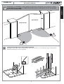 3
3
-
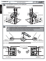 4
4
-
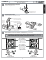 5
5
-
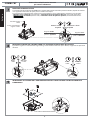 6
6
-
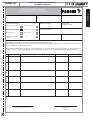 7
7
-
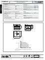 8
8
-
 9
9
-
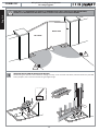 10
10
-
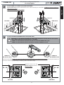 11
11
-
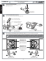 12
12
-
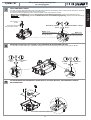 13
13
-
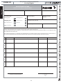 14
14
-
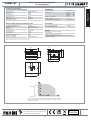 15
15
-
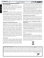 16
16
-
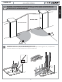 17
17
-
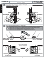 18
18
-
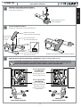 19
19
-
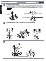 20
20
-
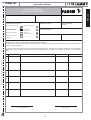 21
21
-
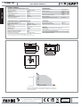 22
22
-
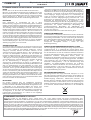 23
23
-
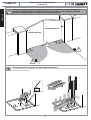 24
24
-
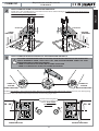 25
25
-
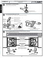 26
26
-
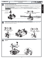 27
27
-
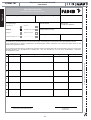 28
28
-
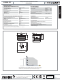 29
29
-
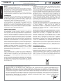 30
30
-
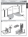 31
31
-
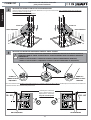 32
32
-
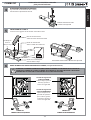 33
33
-
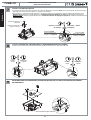 34
34
-
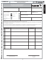 35
35
-
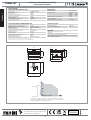 36
36


En otros idiomas
- français: Fadini combi787
- italiano: Fadini combi787
- English: Fadini combi787
- Deutsch: Fadini combi787