Tripp Lite APS Series Manual de usuario
- Categoría
- Adaptadores de corriente
- Tipo
- Manual de usuario
Este manual también es adecuado para

Owner’s Manual
Reliable Emergency Backup Power
Congratulations! You’ve purchased the most advanced, feature-rich Inverter/Charger designed as an alternative energy source during utility
power failures. Tripp Lite APS Inverter/Chargers keep your equipment constantly up and productive through all utility power problems (blackouts,
brownouts and high voltages) by inverting DC power from user-supplied batteries into AC power. Built-in surge suppression provides an additional
level of equipment protection. When utility power is present, APS Inverter/Chargers automatically pass through power to your equipment while
simultaneously recharging your connected battery bank. APS Inverter/Chargers are the quiet alternative to gas generators during emergency
backup applications—with no fumes, fuel or noise to deal with! You get AC electricity anywhere and anytime you need it.
Better for Your Equipment Premium Protection Levels
• Built-In Isobar
®
Surge Protection
• Automatic Overload Protection
Ideal Output for All Loads (including computers)
• Frequency-Controlled Output
• Fast Load Switching
• Balanced Load Sharing*
Better for Your Batteries Faster Battery Recharge
• High-Amp, 3-Stage Battery Charger (adjustable)
Critical Battery Protection
• Battery Charge Conserver (Load Sense)*
• Battery Temperature Sensing*
• High-Efficiency DC-to-AC Inversion
Better for You Simple, Maintenance-Free Operation
• Multi-Function Lights & Switches
• Moisture-Resistant Construction**
Specifications/Warranty 2
Safety 3
Feature Identification 4
Operation 5
Configuration 6-7
Battery Selection 8
Mounting 9
Battery Connection 10
AC Input/Output Connection 11
Service/Maintenance/Troubleshooting 12
Español 13
PowerVerter
®
APS Series
DC-to-AC Inverter/Chargers
Input Output
Invert: 12, 24, 36 or 48 VDC 120V, 60 Hz. AC
Charge: 120V, 60 Hz. AC 12, 24, 36 or 48 VDC
1111 W. 35th Street, Chicago, IL 60609 USA
Customer Support: (773) 869-1234
www.tripplite.com
* Available on all models except 612, 750 and 1250 models. ** Inverter/Chargers are moisture-resistant, not waterproof.
Copyright © 2004. PowerVerter
®
is a registered trademark of Tripp Lite. All rights reserved.
Contents
Warranty
Registration
Register on-line today for a chance
to win a FREE Tripp Lite product!
www.tripplite.com/warranty
200407140 120V APS Owner’s Manual.qxd 9/16/2004 9:58 AM Page 1

2A
Specifications
Note on Labeling
Two symbols are used on the APS labels.
V~: AC Voltage : DC Voltage
Limited Warranty
Tripp Lite warrants its Inverter/Chargers to be free from defects in materials and workmanship for a period of one year (except for outside of U.S.A., Canada and Mexico—120 days) from the date of retail purchase by end user
Tripp Lite’s obligation under this warranty is limited to repairing or replacing (at its sole option) any such defective products. To obtain service under this warranty you must obtain a Returned Material Authorization (RMA) number from Tripp Lite or an authorized Tripp Lite service cen-
ter. Products must be returned to Tripp Lite or an authorized Tripp Lite service center with transportation charges prepaid and must be accompanied by a brief description of the problem encountered and proof of date and place of purchase. This warranty does not apply to equip-
ment which has been damaged by accident, negligence or misapplication or has been altered or modified in any way, including opening of the unit’s casing for any reason. This warranty applies only to the original purchaser who must have properly registered the product with-
in 10 days of retail purchase.
EXCEPT AS PROVIDED HEREIN, TRIPP LITE MAKES NO WARRANTIES, EXPRESS OR IMPLIED, INCLUDING WARRANTIES OF MERCHANTABILITY AND FITNESS FOR A PARTICULAR PURPOSE. Some states do not permit limitation or exclusion of implied war-
ranties; therefore, the aforesaid limitation(s) or exclusion(s) may not apply to the purchaser.
EXCEPT AS PROVIDED ABOVE, IN NO EVENT WILL TRIPP LITE BE LIABLE FOR DIRECT, INDIRECT, SPECIAL, INCIDENTAL OR CONSEQUENTIAL DAMAGES ARISING OUT OF THE USE OF THIS PRODUCT, EVEN IF ADVISED OF THE POSSIBILITY OF SUCH
DAMAGE. Specifically, Tripp Lite is not liable for any costs, such as lost profits or revenue, loss of equipment, loss of use of equipment, loss of software, loss of data, costs of substitutes, claims by third parties, or otherwise.
Tripp Lite has a policy of continuous improvement. Specifications are subject to change without notice.
Inverter/Charger DC Volt: 48
Wire Gauge
Watts 10 8 6 4 2
500 98 ft 156 ft 248 ft 394 ft 626 ft
700 70 ft 111 ft 177 ft 281 ft 447 ft
1000 49 ft 78 ft 124 ft 197 ft 313 ft
2000 25 ft 39 ft 62 ft 99 ft 157 ft
2400 20 ft 32 ft 52 ft 82 ft 131 ft
Inverter/Charger DC Volt: 24
Wire Gauge
Watts 8 6 4 2 0
500 39 ft 62 ft 99 ft 157 ft 249 ft
700 28 ft 44 ft 70 ft 112 ft 178 ft
1000 19 ft 31 ft 49 ft 78 ft 125 ft
2000 10 ft 15 ft 25 ft 39 ft 62 ft
2400 8 ft 13 ft 21 ft 33 ft 52 ft
3000 6 ft 10 ft 16 ft 26 ft 42 ft
Inverter/Charger DC Volt: 12
Wire Gauge
Watts 6 4 2 0 00 (2/0)
500 15 ft 25 ft 39 ft 62 ft 79 ft
700 11 ft 18 ft 28 ft 44 ft 56 ft
1000 8 ft 12 ft 20 ft 31 ft 39 ft
2000 4 ft 6 ft 10 ft 16 ft 20 ft
Minimum Recommended Cable Sizing Charts
†
Use in conjunction with DC wiring connection instructions in the Battery Connection section.
† NOTE: Acceptable power is directly related to cable length (i.e. - the shorter the cable, the better the performance). Cable length is the sum of the positive cable length and the negative cable length.
MODEL NUMBER: APS612 APS750 APS1012 APS1250 APS1524 APS2012 APS2424 APS2448 APS3624VR APS3636VR
AC Input Connection: Input Cord Input Cord Input Cord Input Cord Hardwire Hardwire Hardwire Hardwire Hardwire Hardwire
INVERTER
Common Specifications for All Models
• Output Volts (Nominal): 120 VAC, ± 5% • Output Frequency (Nominal): 60 Hz, ± 0.5% • Efficiency: 88% to 94%, depending on load and temperature
Select Tripp Lite Inverter/Chargers include a Battery Charge Conserver (Load Sense) Control which saves battery power by allowing users to set the minimum load level
at which the unit’s inverter turns on. Users can significantly reduce the No Load DC Input Current to a very low amp level with the use of this control.
Continuous Power (@ 20 C): 600 750 1000 1250 1500 2000 2400 2400 3600 3600
OverPower™ Peak Surge Power:* 900 1125 1500 1875 2250 3000 3600 3600 5400 5400
Double Boost™ Peak Surge Power:* 1200 1500 2000 2500 3000 4000 4800 4800 7200 7200
DC Input Volts (Nominal): 12 VDC 12 VDC 12 VDC 12 VDC 24 VDC 12 VDC 24 VDC 48 VDC 24 VDC 36 VDC
DC Input Voltage Range: 10-15 VDC 10-15 VDC 10-15 VDC 10-15 VDC 20-30 VDC 10-15 VDC 20-30 VDC 40-60 VDC 20-30 VDC 30-45 VDC
Minimum DC Fuse Rating: 100 A 150 A 225 A 225 A 125 A 400 A 300 A 100 A 300 A 300 A
DC Input Current @ Nominal V DC
Full Load 56 A 72 A 95 A 127 A 70 A 192 A 112 A 56 A 170 A 114 A
BATTERY CHARGER
Common Specifications for All Models
• Input Volts (Nominal): 120 VAC
Charging Capacity DC: 20 A 20 A 55 A/14 A** 30 A 36 A/9 A** 100 A/25 A** 55 A/14 A** 15 A/off** 65 A/16 A** 30 A
Acceptance Volts VDC: 14.4 V/14.2 V 14.4 V/14.2 V 14.4 V/14.2 V 14.4 V/14.2 V 28.8 V/28.4 V 14.4 V/14.2 V 28.8 V/28.4 V 57.6 V/56.8 V 28.8 V/28.4 V 43.2 V/42.6 V
Selectable (Wet**/Gel)
Float Volts VDC (w/gel): 13.3 V (13.6 V) 13.3 V (13.6 V) 13.3 V (13.6 V) 13.3 V (13.6 V) 26.6 V (27.2 V) 13.3 V (13.6 V) 26.6 V (27.2 V) 53.2 V (54.4 V) 26.6 V (27.2 V) 39.9 V (40.8 V)
Input Current AC (Maximum): 4.2 A 4.2 A 11.5 A 6.3 A 16 A 21 A 24 A 13.3 A 29 A 20 A
LINE VAC OPERATION
Common Specifications for All Models
• Minimum Input Volts (Transfer to Battery): Selectable 75,** 85, 95 or 105 VAC • Maximum Input Volts (Transfer to Battery): Selectable 135** or 145 VAC • Input Frequency (Nominal): 60 Hz, ±10%
Total Input AC Current
(Continuous, Charger at Maximum): 9.2 A 12 A 14 A 12 A 29 A 38 A 44 A 33 A 59 A 50 A
Maximum Output
Current (Continuous): 5 A 8 A 8.3 A 12 A 12.5 A 16.7 A 20 A 20 A 30 A 30 A
* OverPower duration (up to 1 hour). DoubleBoost duration (up to 10 seconds). Actual duration depends on battery age, battery charge level and ambient temperature. ** Factory setting.
The policy of Tripp Lite is one of continuous improvement. Specifications are subject to change without notice. This product designed and engineered in the USA.
Inverter/Charger DC Volt: 36*
Wire Gauge
Watts 8 6 4 2 0
700 63 ft 100 ft 158 ft 252 ft 400 ft
1000 44 ft 70 ft 111 ft 176 ft 280 ft
2000 22 ft 35 ft 55 ft 88 ft 140 ft
2400 18 ft 29 ft 46 ft 73 ft 117 ft
3000 15 ft 23 ft 37 ft 59 ft 93 ft
3600 12 ft 19 ft 31 ft 49 ft 78 ft
* If your model accepts 4 conductors, simply double the acceptable cable lengths.
Visit www.tripplite.com/warranty
today to register the warranty for
your new Tripp Lite product.You’ll
be automatically entered into a
drawing for a chance to win a
FREE Tripp Lite product!*
* No purchase necessary. Void where
prohibited. Some restrictions apply. See
website for details.
WARRANTY REGISTRATION
200407140 120V APS Owner’s Manual.qxd 9/16/2004 9:58 AM Page 2

3A
Important Safety Instructions
SAVE THESE INSTRUCTIONS!
This manual contains important instructions and warnings that should be followed during the installation, operation and storage of all Tripp Lite
Inverter/Chargers.
Location Warnings
• Install your Inverter/Charger (whether for a mobile or stationary application) in a location or compartment that minimizes exposure to
heat, dust, direct sunlight and moisture.
• Although your Inverter/Charger is moisture resistant, it is NOT waterproof. Flooding the unit with water will cause it to short circuit
and could cause personal injury due to electric shock. Never immerse the unit, and avoid any area where standing water might
accumulate. Mounting should be in the driest location available.
• Leave a minimum of 2" clearance at front and back of the Inverter/Charger for proper ventilation. The heavier the load of connected
equipment, the more heat will be generated by the unit.
• Do not install the Inverter/Charger directly near magnetic storage media, as this may result in data corruption.
• Do not install near flammable materials, fuel or chemicals.
Battery Connection Warnings
• The Inverter/Charger will not operate (with or without utility power) until batteries are connected.
• Multiple battery systems must be comprised of batteries of identical voltage, age, amp-hour capacity and type.
• Because explosive hydrogen gas can accumulate near batteries if they are not kept well ventilated, your batteries should not be
installed (whether for a mobile or stationary application) in a “dead air” compartment. Ideally, any compartment would have some
ventilation to outside air.
• Sparks may result during final battery connection. Always observe proper polarity as batteries are connected.
• Do not allow objects to contact the two DC input terminals. Do not short or bridge these terminals together. Serious personal injury
or property damage could result.
Equipment Connection Warnings
Do not use a Tripp Lite APS Inverter/Charger in life support or healthcare applications where a malfunction or failure of a
Tripp Lite APS Inverter/Charger could cause failure of or significantly alter the performance of, a life support device or medical
equipment.
• Corded models: Do not modify the Inverter/Charger’s plug or receptacle in a way that eliminates its ground connection. Do not use
power adapters that will eliminate the plug’s ground connection.
• Connect your Inverter/Charger only to a properly grounded AC power outlet or hardwired source. Do not plug the unit into itself; this
will damage the device and void your warranty.
• You may experience uneven performance results if you connect a surge suppressor, line conditioner or UPS system to the output of the
Inverter/Charger.
Operation Warnings
• Your Inverter/Charger does not require routine maintenance. Do not open the device for any reason. There are no user serviceable parts
inside.
• Potentially lethal voltages exist within the Inverter/Charger as long as the battery supply and/or AC input are connected. During any
service work, the battery supply and AC input connection should therefore be disconnected.
• Do not connect or disconnect batteries while the Inverter/Charger is operating in either inverting or charging mode. Operating Mode
Switch should be in the OFF position. Dangerous arcing may result.
200407140 120V APS Owner’s Manual.qxd 9/16/2004 9:58 AM Page 3

4A
Feature Identification
Identify the premium features on your specific model and quickly locate instructions on how to maximize their use.
Configuration DIP Switches: optimize Inverter/Charger
operation depending on your application. See pages 6-7 for
setting instructions.
Operating Mode Switch: controls Inverter/Charger operation.
The “AUTO/REMOTE” setting ensures your equipment
receives constant, uninterrupted AC power. It also enables the
Inverter/Charger to be remotely monitored and controlled with
an optional remote module (Tripp Lite model APSRM4, sold
separately or included with select models). The “CHARGE
ONLY” setting allows your batteries to return to full charge
faster by turning the inverter off which halts battery discharging.
See page 5 for setting instructions.
Operation Indicator Lights: intuitive “traffic light” signals
show whether the Inverter/Charger is operating from AC line
power or DC battery power. It also warns you if the connected
equipment load is too high. See page 5 for instructions on reading
indicator lights.
Battery Indicator Lights: intuitive “traffic light” signals show
approximate charge level of your battery. See page 5 for
instructions on reading indicator lights.
DC Power Terminals: connect to your battery terminals. See
page 10 for connection instructions.
AC Receptacles (not on hardwire models): allow you to connect
equipment that would normally be plugged into a utility outlet.
AC Input Cord (not on hardwire models): connects the
Inverter/Charger to any source of utility- or generator-supplied AC
power. See page 11 for connection instructions.
Hardwire AC Input/Output Terminal Strip (not on corded
models): securely connects the Inverter/Charger to facility or
vehicle electrical system. See page 11 for connection instructions.
Resettable Circuit Breakers: protect your Inverter/Charger
against damage due to overload. See page 5 for resetting instructions.
Remote Control Module Connector: allows remote monitoring
and control with an optional module (Tripp Lite model
APSRM4, sold separately or included with select models). See
remote module owner’s manual for connection instructions.
Battery Charge Conserver (Load Sense) Control (available
on select models): conserves battery power by setting the
low-load level at which the Inverter/Charger’s inverter automat-
ically shuts off. See page 7 for setting instructions.
Main Ground Lug: properly grounds the Inverter/Charger to
earth ground or to vehicle or boat grounding system. See page
10 for connection instructions.
Thermostatically-Controlled Cooling Fan: quiet, efficient fan
regulates internal temperature and prolongs equipment service life.
Fan runs intermittently depending on temperature and load.
DC Power Terminal Cover Plate
Hardwire AC Input/Output Cover Plate
Battery Temperature Sensing Connector (available on select
models): prolongs battery life by adjusting charge based on battery
temperature. Use with cable (included on select models). See page
7 for details.
Voltage Regulation Indicator Lights (available on select models):
shows when the Inverter/Charger is automatically “boosting”
abnormally low AC voltage or “cutting” abnormally high AC voltage
without relying on battery power. This function is automatic and
requires no action on the user’s part.
Redundant Switch/Indicator Light Panel (available on select
models): additional top mounted switch/indicator light panel allows
easy control and monitoring when Inverter/Charger is vertically mounted.
1
2
3
4
5
6
7
8
9
10
11
12
13
14
15
Front View (1012 Corded Models)
HOT IN
NEUTRAL IN
GROUND IN
GROUND OUT
HOT OUT
“FOR USE WITH COPPER WIRE ONLY”
NEUTRAL OUT
1 24 3
5
6
9
10
111314
1
24 3
5
9
10 111314
8 15
Front View (All Hardwire Models except APS3624VR).
16
16
Side Mounted, Not Shown
16
Side Mounted, Not Shown

5A
Operation
Switch Modes
After configuring, mounting and connecting your Inverter/Charger, you
are able to operate it by switching between the following operating
modes as appropriate to your situation:
AUTO/REMOTE: Switch to this mode when you
need constant, uninterrupted AC power for connected
appliances and equipment. The Inverter/Charger will
continue to supply AC power to connected equipment
and to charge your connected batteries while utility-
or generator-supplied AC power is present. Since the
inverter is ON (but in Standby) in this mode, it will automatically
switch to your battery system to supply AC power to connected
equipment in the absence of a utility/generator source or in over/under
voltage situations. “AUTO/REMOTE” also enables an optional
remote control module (Tripp Lite model APSRM4, sold separately
or included with select models) to function when connected to the
unit. This setting also allows operation of the Redundant Operating
Mode Switch mounted on the top panel of select models
CHARGE ONLY: Switch to this mode when you
are not using connected appliances and equipment in
order to conserve battery power by disabling the
inverter. The Inverter/Charger will continue to supply
AC power to connected equipment and charge con-
nected batteries while utility- or generator-supplied
AC power is present. However, since the inverter is OFF in this
mode, it WILL NOT supply AC power to connected equipment in the
absence of a utility/generator source or in over/under voltage situations.
OFF: Switch to this mode to shut down the
Inverter/Charger completely, preventing the inverter
from drawing power from the batteries, and preventing
utility AC from passing through to connected equipment
or charging the batteries. Use this switch to automatically
reset the unit if it shuts down due to overload or over-
heating. First remove the excessive load or allow the unit to suffi-
ciently cool (applicable to your situation). Switch to “OFF”, then
back to “AUTO/REMOTE” or “CHARGE ONLY” as desired. If
unit fails to reset, remove more load or allow unit to cool further and
retry. Use an optional remote control module (Tripp Lite model
APSRM4, sold separately or included with select models) to reset
unit due to overload only.
Indicator Lights
Your Inverter/Charger (as well as an optional Tripp Lite Remote
Control Module, sold separately or included with select models) is
equipped with a simple, intuitive, user-friendly set of indicator lights.
These easily-remembered “traffic light” signals will allow you, shortly
after first use, to tell at a glance the charge condition of your batteries,
as well as ascertain operating details and fault conditions.
LINE Green Indicator: If the operating mode
switch is set to “AUTO/REMOTE,” this light will
ILLUMINATE CONTINUOUSLY when your con-
nected equipment is receiving continuous AC power
supplied from a utility/generator source.
If the operating mode switch is set to “CHARGE ONLY,” this light
will FLASH to alert you that the unit’s inverter is OFF and will NOT
supply AC power in the absence of a utility/generator source or in
over/under voltage situations.
INV (Inverting) Yellow Indicator: This light will
ILLUMINATE CONTINUOUSLY whenever connected
equipment is receiving battery-supplied, inverted AC
power (in the absence of a utility/generator source or
in over/under voltage situations). This light will be
off when AC power is supplying the load. This light
will FLASH to alert you if the load is less than the Battery Charge
Conserver (Load Sense) setting.
LOAD Red Indicator: This red light will ILLUMI-
NATE CONTINUOUSLY whenever the inverter is
functioning and the power demanded by connected
appliances and equipment exceeds 100% of load
capacity. The light will FLASH to alert you when the
inverter shuts down due to a severe overload or over-
heating. If this happens, turn the operating mode switch “OFF”;
remove the overload and let the unit cool. You may then turn the
operating mode switch to either “AUTO/REMOTE” or “CHARGE
ONLY” after it has adequately cooled. This light will be off when
AC power is supplying the load.
BATTERY Indicator Lights: These three lights will illuminate in
several sequences to show the approximate charge level of your con-
nected battery bank and alert you to two fault conditions:
Approximate Battery Charge Level*
Indicator Illuminated Battery Capacity
(Charging/Discharging)
Green 91%–Full
Green & Yellow 81%–90%
Yellow 61%–80%
Yellow & Red 41%–60%
Red 21%–40%
All three lights off 1%–20%
Flashing red 0% (Inverter
shutdown)
* Charge levels listed are approximate. Actual conditions vary
depending on battery condition and load.
Fault Condition
Indicator Illuminated Fault Condition
All three lights Excessive discharge
flash slowly* (Inverter shutdown)
All three lights Overcharge (Charger
flash quickly** shutdown)
*Approximately ½ second on, ½ second off. See Troubleshooting section. ** Approximately ¼ sec-
ondon, ¼ second off. May also indicate a battery charger fault exists. See Troubleshooting sec-
tion.
Voltage Regulation Indicator Lights (available on
select models): these green lights will illuminate to
indicate when the Inverter/Charger is automatically
“boosting” abnormally low AC voltage or “cutting”
abnormally high AC voltage without relying on bat-
tery power. This function is automatic and requires
no action on the user’s part.
Resetting Your Inverter/Charger
to Restore AC Power
Your Inverter/Charger may cease supplying AC power or DC charging
power in order to protect itself from overload or to protect your elec-
trical system. To restore normal functioning:
Overload Reset: Switch operating mode switch to “OFF” and
remove some of the connected electrical load (ie: turn off some of
the AC devices drawing power which may have caused the overload
of the unit). Wait one minute, then switch operating mode switch
back to either “AUTO/REMOTE” or “CHARGE ONLY.”
Output Circuit Breaker Reset: Alternatively, check output circuit
breaker(s) on the unit’s front panel. If tripped, remove some of the elec-
trical load, then wait one minute to allow components to cool before
resetting the circuit breaker. See Troubleshooting for other possible
reasons AC output may be absent.
1
2
3
4
5
6
7
1
2
1
2 3
4
5
6
7
1
2
See page 11 for Redundant Switch/Indicator Light Panel
200407140 120V APS Owner’s Manual.qxd 9/16/2004 9:58 AM Page 5

6A
Configuration
Select Battery Type—REQUIRED
CAUTION: The Battery Type DIP Switch setting must
match the type of batteries you connect, or your batteries
may be degraded or damaged over an extended period of
time. See “Battery Selection,” p. 8 for more information.
Battery Type Switch Position
Gel Cell (Sealed) Battery Up
Wet Cell (Vented) Battery Down (factory setting)
Select High AC Input Voltage Point
for Switching to Battery—OPTIONAL*
Voltage Switch Position
145V Up
135V Down (factory setting)
Set Configuration DIP Switches
Using a small tool, set the Configuration DIP Switches (located on the front panel of your unit, see diagram) to optimize Inverter/Charger
operation depending on your application. 612, 750 and 1250 models have one set of four DIP Switches (Group A). All other models include
an additional set of four DIP switches (Group B) to configure additional operational functions.
A1A2A3A4
INPUT C/B 10A
OUTPUT C/B 12A
B4 B3 B2 B1
A4 A3 A2 A1
Group B Dip Switches (Select Models)
Group A Dip Switches (All Models)
Group A DIP Switches (All Models)
Select Low AC Input Voltage Point for Switching to
Battery—OPTIONAL*
Voltage Switch Position
105V #A4 Up & #A3 Up
95V #A4 Up & #A3 Down
85V #A4 Down & #A3 Up
75V #A4 Down & #A3 Down
(factory setting)
* Most of your connected appliances and equipment will perform adequately when your Inverter/Charger’s High AC Input Voltage Point is left in the factory setting and its Low AC Voltage Input
Point is set to 95V. However, if the unit frequently switches to battery power due to momentary high/low line voltage swings that would have little effect on equipment operation, you may wish to
adjust these settings. By increasing the High AC Voltage Point and/or decreasing the Low AC Voltage Point, you will reduce the number of times your unit switches to battery due to voltage swings.
Group B DIP Switches (Select Models)
Select Load Sharing—OPTIONAL (Not on 612, 750 and 1250 Models)
Your Inverter/Charger features a high-output battery charger that can draw a significant amount of AC power from your utility source or
generator when charging at its maximum rate. If your unit is supplying its full AC power rating to its connected heavy electrical loads at the
same time as this high charging occurs, the AC input circuit breaker could trip, resulting in the complete shut off of pass-through utility power.
To reduce the chance of tripping this breaker, Inverter/Chargers may be set to automatically limit the charger output. This keeps the sum of
the unit’s AC load and charge power within the circuit breaker rating. This charger-limiting function has four settings, allowing you to
reduce the charger’s draw lower and lower, as needed, if the AC input circuit breaker keeps tripping under the normal AC loads of devices
you have connected downline from the unit. The figures on the next page show how to set your DIP Switches to determine how heavy the
connected load can be on your Inverter/Charger before charger-limiting begins.
A1
A2
A3
A4
B2
B1
A1A2A3A4
A1A2A3A4
A1A2A3A4
A1A2A3A4
A1A2A3A4
200407140 120V APS Owner’s Manual.qxd 9/16/2004 9:58 AM Page 6

7A
Configuration
(continued)
Set Battery Charging Amps—OPTIONAL
(Not on 612, 750 or 1250 Models)
Check specifications for your unit’s high-
and low-charging amp options. By setting
on high charging, your batteries will
charge at maximum speed. When setting
on low charging, you lengthen the life of
your batteries (especially smaller ones).
Battery Charger Switch Position
Low Charge Amps Up (factory setting)
High Charge Amps Down
CAUTION: When switching to the High Charge Amp setting, the user must ensure that the amp
hour capacity of their battery system exceeds the amperage of the High Charge Amp setting or
the batteries may be damaged or degraded.
Select Equalize Battery Charge—OPTIONAL
(Not on 612, 750 or 1250 Models)
This DIP Switch is momentarily engaged
to begin the process of equalizing the
charge state of your battery’s cells by time-
limited overcharge of all cells. This can
extend the useful life of certain types of batteries; consult with your
battery’s manufacturer to determine if your batteries could benefit
from this process. The charge equalization process is automatic;
once started, it can only be stopped by removing the input power.
Setting Procedure
• Move to “Equalize” (DOWN) position for three seconds.
• Move to “Reset” (UP) position and leave it there. This is the
factory default setting.
CAUTION: Do not leave DIP switch #3 in the down position after beginning process. Battery
charge equalization should only be performed in strict accordance with the battery manufacturer’s
instructions and specifications.
Battery Charge Switch Position
Reset Up (factory setting)
Equalize Down—momentarily
Select Battery Charger-Limiting
Points—OPTIONAL
(Not on 612, 750 or 1250 Models)
Most Limiting (#B1 & #B2 Up, factory set-
ting): Charger-limiting takes effect the
moment any 120V AC load is applied; charger output falls gradual-
ly from full output at no 120V load passing through to no output at
full load.
Less Limiting (#B1 Down & #B2 Up):
Charger-limiting begins when the
Inverter/Charger’s load reaches 33% of the
Inverter/Charger’s load rating. Charger
output falls gradually from full output at
33% of the Inverter/Charger’s load rating to about 33% of full output
at full load.
Least Limiting (#B1 Up & #B2 Down):
Charger-limiting begins at when the
Inverter/Charger’s load reaches 66% of the
Inverter/Charger’s load rating. Charger
output falls gradually from full output at
66% of the Inverter/Charger’s load rating to about 66% of full output
at full load.
No Limiting (#B1 & #B2 Down): No
charger-limiting occurs at any load size.
B1B2B3B4
B1B2B3B4
B1B2B3B4
B1B2B3B4
B1B2B3B4
Set Battery Charge Conserver (Load Sense) Control—OPTIONAL (Not on 612, 750 or 1250 Models)
In order to save battery power, the unit's inverter automatically shuts off in the absence of any power demand from
connected equipment or appliances (the electrical load). When the Inverter/Charger detects a load, it automatical-
ly turns its inverter function on. Users may choose the minimum load the Inverter/Charger will detect by adjusting
the Battery Charge Conserver Control (see diagram). Using a small tool, turn the control clockwise to lower the
minimum load that will be detected, causing the inverter to turn on for smaller loads. When the control is turned
fully clockwise, the inverter will operate even when there is no load. Turn the control counterclockwise to increase the minimum load that
will be detected, causing the inverter to stay off until the new minimum load is reached.
NOTE: The factory setting for the control is fully clockwise. However, based on the threshold load to which you’d like the inverter to respond, you should adjust the control counterclockwise to reduce
its sensitivity until the inverter is active only when connected equipment or appliances are actually in use.
Connect Remote Control—Optional (All models)
All models feature an 8-conductor telephone style receptacle on the front panel for use with an optional remote control module (Tripp Lite
model APSRM4, sold separately or included with select models). The remote module allows the Inverter/Charger to be mounted in a compart-
ment or cabinet out of sight, while operated conveniently from a remote location. See instructions packed with the remote control module.
Connect Battery Temperature Sensing Cable—OPTIONAL (Select Models)
The battery temperature sensing function prolongs battery life by adjusting the charge float voltage level based on battery temperature. Connect
the sensor cable (the cable, included with select models, has an RJ style connector on one end and a black sensor on the other) to the RJ
style jack located on the side of the Inverter/Charger labeled “Remote Temp. Sense.” Affix the sensor to the side of your battery below the
electrolyte level. To guard against false readings due to ambient temperature, place the sensor between batteries, if possible, or away from
sources of extreme heat or cold. If the sensor cable is not used, the Inverter/Charger will charge according to its default 25º C values.
Reset
Equaliz
e
B1B2B3B4
OFF
(LESSER
LOAD
ON)
MAX
(GREATER
LOAD
ON)
B4
B3
200407140 120V APS Owner’s Manual.qxd 9/16/2004 9:58 AM Page 7

8A
Battery Selection
540 watts ÷ 12V = 45 DC Amps
45 DC Amps × 5 Hrs. Runtime
× 1.2 Inefficiency Rating = 270 Amp-Hours
270 Amp-Hours ÷ 30 Amps
Inverter/Charger Rating = 9 Hours Recharge
Select Battery Type
Select “Deep Cycle” batteries to enjoy optimum performance from your Inverter/Charger. Batteries of either Wet-Cell (vented) or Gel-Cell /Absorbed
Glass Mat (sealed) construction are ideal. 6-volt “golf cart,” Marine Deep-Cycle or 8D Deep-Cycle batteries are also acceptable. You must
set the Inverter/Charger’s Battery Type DIP Switch (see Configuration section for more information) to match the type of batteries you connect
or your batteries may be degraded or damaged over an extended period of time.
Match Battery Amp-Hour Capacity to Your Application
Select a battery or system of batteries that will provide your Inverter/Charger with proper DC voltage and an adequate amp-hour capacity
to power your application. Even though Tripp Lite Inverter/Chargers are highly-efficient at DC-to-AC inversion, their rated output capacities
are limited by the total amp-hour capacity of connected batteries plus the output of an alternator when one is used.
• STEP 1) Determine Total Wattage Required
Add the wattage ratings of all equipment you will connect to your
Inverter/Charger. Wattage ratings are usually listed in equipment manuals
or on nameplates. If your equipment is rated in amps, multiply that number
times AC utility voltage to estimate watts. (Example: a ¼ in. drill requires
2½ amps. 2½ amps × 120 volts = 300 watts.)
NOTE: Your Inverter/Charger will operate at higher efficiencies at about 75% - 80% of nameplate rating.
• STEP 2) Determine DC Battery Amps Required
Divide the total wattage required (from step 1, above) by the battery voltage
(i.e. 12, 24, 36 or 48) to determine the DC amps required.
• STEP 3) Estimate Battery Amp-Hours Required
Multiply the DC amps required (from step 2, above) by the number of hours
you estimate you will operate your equipment exclusively from battery
power before you have to recharge your batteries with utility- or genera-
tor-supplied AC power. Compensate for inefficiency by multiplying this
number by 1.2. This will give you a rough estimate of how many amp-hours
of battery power (from one or several batteries) you should connect to
your Inverter/Charger.
NOTE: Battery amp-hour ratings are usually given for a 20-hour discharge rate. Actual amp-hour capacities
are less when batteries are discharged at faster rates. For example, batteries discharged in 55 minutes
provide only 50% of their listed amp-hour ratings, while batteries discharged in 9 minutes provide as little
as 30% of their amp-hour ratings.
• STEP 4) Estimate Battery Recharge Required, Given Your Application
You must allow your batteries to recharge long enough to replace the
charge lost during inverter operation or else you will eventually run down
your batteries. To estimate the minimum amount of time you need to
recharge your batteries given your application, divide your required battery
amp-hours (from step 3, above) by your Inverter/Charger’s rated charging
amps (see Specifications section).
NOTE: For Tripp Lite Inverter/Chargers providing 1000 watts or less of continuous AC power, a full-size
battery will normally allow sufficient power for many applications before recharging is necessary. For
mobile applications, if a single battery is continuously fed by an alternator at high idle or faster, then recharging
from utility or generator power may not be necessary. For Tripp Lite Inverter/Chargers over 1000 watts used
in mobile applications, Tripp Lite recommends you use at least two batteries, if possible fed by a heavy-duty
alternator anytime the vehicle is running. Tripp Lite Inverter/Chargers will provide adequate power for
ordinary usage within limited times without the assistance of utility or generator power. However, when
operating extremely heavy electrical loads at their peak in the absence of utility power, you may wish to
“assist your batteries” by running an auxiliary generator or vehicle engine, and doing so at faster than
normal idling.
Example
Tools

9A
Mounting
WARNING! Mount your Inverter/Charger BEFORE DC battery and AC power
connection. Failure to follow these instructions may lead to personal injury
and/or damage to the Inverter/Charger and connected systems.
Tripp Lite manufactures a variety of different Inverter/Chargers with a variety of different mounting options for use in vehicular or non-vehicular
applications. Tripp Lite recommends permanent mounting of your Inverter/Charger in any of the configurations illustrated below. User must
supply mounting hardware and is responsible for determining if the hardware and mounting surface are suitable to support the weight of the
Inverter/Charger. Contact Tripp Lite if you require further assistance in mounting your Inverter/Charger.
Vehicular and Non-Vehicular Horizontal Mount
(612, 750 and 1250 models only)
Using the measurements from the diagram, install two user-sup-
plied ¼" (6 mm) fasteners into a rigid horizontal surface, leaving
the heads slightly raised. Slide the Inverter/Charger back over
the fasteners to engage the mounting slots molded on the bottom of
the Inverter/Charger cabinet. Install and tighten two user-sup-
plied ¼" (6 mm) fasteners into the mounting feet molded on the
front of the Inverter/Charger cabinet.
Vehicular and Non-Vehicular Horizontal Mount
and Non-Vehicular Vertical Mount
(All models except 612, 750, 1250 and 3624)
Using the measurements from the diagram, install two user-sup-
plied ¼" (6 mm) fasteners into a rigid surface, leaving the heads
slightly raised. Slide the Inverter/Charger forward over the
fasteners to engage the mounting feet molded on the front of the
Inverter/Charger cabinet. Install and tighten two user-supplied
¼" (6 mm) fasteners into the mounting feet molded on the rear
of the Inverter/Charger cabinet. The rear feet extend beyond the
unit’s cabinet to provide for adequate ventilation space behind the
cooling fan(s); they should not be removed.
A
B
C
A
B
C

10A
Non-Vehicular or Vehicular
Non-vehicular applications include stationary configurations as well as mobile configurations that are not integrated into a vehicle’s electrical
system. In a parallel connection, your Inverter/Charger’s Nominal DC Input Voltage (listed in the Specifications section as either 12, 24,
36 or 48) must match the voltage of your battery or batteries (12, 24, 36 or 48). For example, a 12V DC Inverter/Charger would require
12V DC from your battery system.
In a series connection, your Inverter/Charger’s Nominal DC Input Voltage must match the number of batteries multiplied by their voltage. For
example, a 24V DC Inverter/Charger would require either two 12V batteries connected in series (24 = 2 × 12) or four 6V batteries connected
in series (24 = 4 × 6).
In vehicular applications, your Inverter/Charger’s Nominal DC Input Voltage must match the voltage of your battery or batteries—
12 Volts. Although it is possible to connect your Inverter/Charger to the main battery within your vehicle’s electrical system, in the normal
vehicular context, the Inverter/Charger is connected to one or more dedicated auxiliary (house) batteries which are isolated from the drive
system to prevent possible draining of the main battery.
Contact Tripp Lite technical support for assistance with additional parallel, series or series/parallel connections.
Note: X=Your Inverter/Charger’s Nominal DC Input Voltage (listed in the specifications section as either 12, 24, 36 or 48)
Earth or Vehicle/Boat Battery Ground Battery UL-Listed Fuse & Fuse Block (mounted within 18 inches of the battery) Large Diameter
Cabling, Maximum 2/0 Gauge to Fit Terminals Alternator (for vehicle or boat connection only)
NOTE: Select models include two positive and two negative DC terminals. Using the same connection architecture illustrated in the diagrams, run two 2/0 gauge cables from the Inverter/Charger’s
two negative terminals to the battery’s single negative terminal; run two 2/0 gauge cables from the Inverter/Charger’s two positive terminals, through two UL-listed fuses and fuse blocks, or equivalent,
(one on each cable), to the battery’s single positive terminal. Use the equivalent of two 2/0 cables in all other connections within the battery system. Connection to two DC Terminals: It is acceptable to
use two cables to connect your battery to only one positive and one negative DC terminal, however, your Inverter/Charger will provide reduced output power. It doesn’t make a difference which pos-
itive and negative terminal you choose for the connection because both positive terminals are internally bonded and both negative terminals are also internally bonded. In this connection, you must
run one positive cable through one user-supplied UL-listed fuse and fuse block.
5
4321
X Volts Inverter/Charger
X Volts
Single Battery Connection
4
1
2
3
24 Volt Inverter/Charger
6 Volts
6 Volts 6 Volts 6 Volts
Multiple Battery Connection (Series)—
24 Volt Shown
1
2 2 2 2 4
3
Battery Connection
5
Optional connection
for Vehicular
• Connect DC Wiring: Though your
Inverter/Charger is a
high-efficiency con-
verter of electricity,
its rated output
capacity is limited by
the length and gauge
of the cabling run-
ning from the bat-
tery to the unit. Use
the shortest length
and largest diameter
cabling (maximum
2/0 gauge) to fit
your Inverter/Charger’s DC Input terminals.
Shorter and heavier gauge cabling reduces
DC voltage drop and allows for maximum
transfer of current. Your Inverter/Charger is
capable of delivering peak wattage at up to
200% of its rated continuous wattage output
for brief periods of time. See Specifications
page for details. Heavier gauge cabling
should be used when continuously operating
heavy draw equipment under these conditions.
Tighten your Inverter/Charger and battery
terminals to approximately 3.5 Newton-
meters of torque to create an efficient con-
nection and to prevent excessive heating at
this connection. Insufficient tightening of
the terminals could void your warranty. See
Specifications page for Minimum
Recommended Cable Sizing Chart.
• Connect Ground: Using a #8 AWG wire
or larger directly connect the Main Ground
Lug to the vehicle’s chassis or earth ground.
See the Feature Identification section to locate
the Main Ground Lug on your specific
Inverter/Charger model. All installations
must comply with national and local codes
and ordinances.
• Connect Fuse: NEC (National Electrical
Code) article 551 requires that you connect
all of your Inverter/Charger’s positive DC
Terminals directly to a UL-listed fuse(s) and
fuse block(s) within 18 inches of the battery.
The fuse’s rating must equal or exceed the
Minimum DC Fuse Rating listed in your
Inverter/Charger’s specifications. See
Specifications for fuse and fuse block rec-
ommendations. See diagrams below for
proper fuse placement.
Connect your Inverter/Charger to your batteries using the following procedures:
WARNING! • Failure to properly ground your Inverter/Charger to a vehicle’s chassis or earth
ground may result in a lethal electrical shock hazard.
• Never attempt to operate your Inverter/Charger by connecting it directly to output from an
alternator rather than a battery or battery bank.
• Observe proper polarity with all DC connections.
DC Connectors
Dual DC Connectors (See
note at bottom of the page)
200407140 120V APS Owner’s Manual.qxd 9/16/2004 9:58 AM Page 10

11A
AC Input/Output Connection
To avoid overloading your Inverter/Charger, be sure to match the power requirements of the equipment you plan to run at any one time (add their
total watts) with the output wattage capacity of your Inverter/Charger model (see Specifications). When figuring the power requirements
of your equipment, do not confuse “continuous” wattage with “peak” wattage ratings. Most electric motors require extra power at start-up
(“peak” wattage) than required to run continuously after start-up, sometimes over 100% more. Some motors, such as in refrigerators and
pumps, start and stop intermittently according to demand, requiring “peak” wattage at multiple, unpredictable times during operation.
Connection for Models with Cords and Receptacles
Plug the Inverter/Charger’s AC input cord into an outlet providing 120V AC, 60Hz. power. Make sure that the circuit you connect your
Inverter/Charger to has adequate overload protection, such as a circuit breaker or a fuse. To make use of AC output (either utility/genera-
tor pass-through power or inverter power) simply plug your equipment into the Inverter/Charger's AC receptacles. Any equipment you con-
nect to it will benefit from your Inverter/Charger’s built-in ISOBAR
®
surge protection!
Warning! Consult a qualified electrician and follow all applicable electrical codes
and requirements for hardwire connection. Disconnect both DC input and AC utility
supply before attempting hardwiring.
Connection for Models with Hardwire Terminals
Remove the screws and cover plate over the hardwire terminal box. Remove the knockout covers closest to the desired electrical source and
to your equipment. Attach ½" diameter conduits (user-supplied) to the knockouts and thread wires through. Connect the conduits to each
other with the ground bond connection supplied.
HOT IN
NEUTRAL IN
GROUND IN
GROUND OUT
HOT OUT
“FOR USE WITH COPPER WIRE ONLY”
NEUTRAL OUT
Ground*
• Connect the incoming and outgoing ground wires to the
ground (green) terminal .
AC Input
• Connect the incoming hot wire to the input hot
(brown) terminal .
• Connect the incoming neutral wire to the input neutral (blue)
terminal .
AC Output
• Connect the outgoing hot wire to the output hot
(black) terminal .
• Connect the outgoing neutral wire to the output neutral (white)
terminal .
Replace cover plate and tighten screws.* If the incoming conduit only contains two wires (hot
and neutral), the incoming conduit must be bonded to the main ground lug on the unit. In any
case, the incoming conduit must be bonded to earth or vehicle ground, and the incoming con-
duit must be bonded to the outgoing conduit.
2
3
1
4
5
1
2
3
4
5
• DoubleBoost
™
Feature
Tripp Lite Inverter/Chargers deliver up to twice their nameplate
rated wattage for up to 10 seconds,* providing the extra power
needed to cold start heavy-duty tools and equipment.
• OverPower
™
Feature
Tripp Lite Inverter/Chargers deliver up to 150% of their name
plate rated wattage for up to 1 hour,* providing plenty of reserve
power to reliably support tools and equipment longer.
* Actual duration depends on battery age, battery charge level and ambient temperature.
Additional top mounted switch/indicator light panel allows easy control and monitoring when Inverter/Charger is
vertically mounted. Activate by setting Operating Mode Switch (located on the front panel) to
“AUTO/REMOTE.” Top panel indicator light function is identical to the front panel indicator lights. Top panel
“AUTO” and “CHRG ONLY” (Charge Only) switch settings are identical to the front panel Operating Mode
Switch settings.
Redundant Switch/Indicator Light Panel (available on select models)
200407140 120V APS Owner’s Manual.qxd 9/16/2004 9:58 AM Page 11

12A
Service
If you are returning your Inverter/Charger to Tripp Lite, please pack it carefully, using the ORIGINAL PACKING MATERIAL that came
with the unit. Enclose a letter describing the symptoms of the problem. If the Inverter/Charger is within the warranty period, enclose a copy
of your sales receipt. To obtain service you must obtain a Returned Material Authorization (RMA) number from Tripp Lite or an author-
ized Tripp Lite service center.
Your Inverter/Charger requires no maintenance and contains no user-serviceable or replaceable parts, but should be kept dry at all times.
Periodically check, clean and tighten all cable connections as necessary, both at the unit and at the battery.
Try these remedies for common Inverter/Charger problems before calling for assistance. Call Tripp Lite Customer Service at (773) 869-1234
before returning your unit for service.
Maintenance
Troubleshooting
SYMPTOM PROBLEMS CORRECTIONS
No AC Output Unit is not properly connected to utility power. Connect unit to utility power.
(All Indicator Lights Are OFF) Operating Mode Switch is set to “OFF” and Set Operating Mode Switch to “AUTO/REMOTE” or “CHARGE ONLY.”
AC input is present.
This is normal when the Operating Mode Switch No correction is required. AC output will return when AC input
is set to “CHARGE ONLY” and AC input is absent. returns. Set Operating Mode Switch to “AUTO/REMOTE” if you
require AC output.
Circuit breaker is tripped. Reset circuit breaker.
Unit has shut down due to battery overcharge (preventing Disconnect any auxiliary chargers. Reset by moving Operating
battery damage). The problem may be with connected Mode Switch to “OFF.” Wait 1 minute and switch to “AUTO/REMOTE”
auxiliary chargers, if any, or with the unit’s charger. or “CHARGE ONLY.” If unit remains in shutdown mode after several
attempts to reset, contact Tripp Lite Customer Service for assistance.
Unit has shut down due to excessive battery discharge. Use an auxiliary charger* to raise battery voltage. Check external
battery connections and fuse. Unit automatically resets when
condition is cleared.
Unit has shut down due to overload. Reduce load. Reset by moving Operating Mode Switch to “OFF.”
Wait 1 minute. Switch to “AUTO/REMOTE” or “CHARGE ONLY.”
Battery Not Recharging Connected batteries are dead. Check and replace old batteries.
(AC Input Present) Battery fuse* is blown. Check and replace fuse.*
Battery cabling* is loose. Check and tighten or replace cabling.*
Unit has shut down due to battery overcharge (preventing Disconnect any auxiliary chargers. Reset by moving Operating Mode
battery damage). The problem may be with connected Switch to “OFF.” Wait 1 minute and switch to “AUTO/REMOTE” or
auxiliary chargers, if any, or with the unit’s charger. “CHARGE ONLY.” If unit remains in shutdown mode after several
attempts to reset, contact Tripp Lite Customer Service for assistance.
Input circuit breaker is tripped. Reset circuit breaker.
All Three Battery Indicator Lights Battery is excessively discharged. Use an auxiliary charger* to raise battery voltage. Check external
Are Slowly Flashing battery connections and fuse. Unit automatically resets when
(½ Second Flashes) condition is cleared.
All Three Battery Indicator Lights Battery is overcharged. Unit will shut down to prevent Disconnect any auxiliary chargers. Reset by moving Operating Mode
Are Rapidly Flashing battery damage. The problem may be with connected Switch to “OFF.” Wait 1 minute and switch to “AUTO/REMOTE”
(¼ Second Flashes) auxiliary chargers, if any, or with the unit’s charger. or “CHARGE ONLY.” If unit remains in shutdown mode after several
attempts to reset, contact Tripp Lite Customer Service for assistance.
Red “LOW” Battery Battery voltage is low. Unit will automatically shut down Make sure that AC power is present in order to recharge batteries.
Indicator Light is Flashing after 5 seconds to protect battery from damage. Reset by moving Operating Mode Switch to “OFF then to
“AUTO/REMOTE” or “CHARGE ONLY.”
False reading due to undersized or insufficiently connected Use sufficient size DC cable sufficiently connected to the
DC cabling. Inverter/Charger.
Red “LOAD” Operation Inverter is overloaded. Unit will automatically shut down Reduce load. Reset by moving Operating Mode Switch to “OFF.”
Indicator Light Flashing after 5 seconds. Wait 1minute. Switch to “AUTO/REMOTE” or “CHARGE ONLY.”
Green “BOOST” or “CUT” Indicator Lights This is a normal function. No action is required on the user’s part.
(available on select models) Flashing
* User-supplied.
OFF
(LESSER
LOAD
ON)
MAX
(GREATER
LOAD
ON)
Battery Indicator Lights
Operating Mode Switch
Operation Indicator Lights
200407140 120V APS Owner’s Manual.qxd 9/16/2004 9:58 AM Page 12

Manual del Propietario
Confiable energía de respaldo de emergencia
¡Felicitaciones! Ha adquirido el inversor/cargador más avanzado y con más funciones, diseñado como una fuente alternativa de energía durante fallas del
suministro de energía de la red. Los inversores/cargadores Tripp Lite APS mantienen sus equipos constantemente en operación y productivos durante cualquier
problema de energía de la red (fallas del servicio eléctrico, bajas de voltaje y voltajes altos) convirtiendo la energía de corriente continua de baterías
suministradas por el usuario, en energía de corriente alterna. La supresión de sobretensiones integrada proporciona un nivel adicional de protección al equipo.
Cuando hay energía de la red, los inversores/cargadores APS pasan automáticamente la energía a sus equipos, y recargan simultáneamente el banco de baterías
conectado. Los inversores/cargadores APS son la alternativa silenciosa a los generadores de gasolina durante aplicaciones de respaldo de emergencia-¡sin humo,
combustible ni ruido! Obtiene electricidad de corriente alterna en cualquier lugar y en cualquier momento en que la necesite.
Mejor para su equipo Niveles de protección Premium
• Protección contra sobretensiones integrada Isobar
®
• Protección automática de sobrecarga
Salida ideal para cualquier carga (incluyendo computadoras)
• Salida controlada por frecuencia
• Rápida conmutación de carga
• Reparto de carga balanceada*
Mejor para sus baterías Recarga de baterías más rápida
• Cargador de baterías de 3 etapas de alta capacidad (ajustable)
Protección crítica de batería
• Conservador de carga de batería (Detección de carga)*
• Detección de temperatura de batería*
• Inversión de CC a CA de alta eficiencia
Mejor para usted Operación simple, sin mantenimiento
• Luces y conmutadores multifunción
• Fabricación resistente a la humedad**
Especificaciones/Garantía 14
Seguridad 15
Identificación de funciones 16
Operación 17
Configuración 18-19
Selección de baterías 20
Montaje 21
Conexión de la batería 22
Conexión de entrada/salida de
corriente alterna 23
Servicio/Mantenimiento/Solución 24
de problemas
PowerVerter
®
Serie APS
Inversores/cargadores de corriente
continua a corriente alterna
Entrada Salida
Inversión: 12, 24, 36 o 48 VCC 120V, 60 Hz. VAC
Carga: 120V, 60 Hz. AC 12, 24, 36 o 48 VCC
1111 W. 35th Street, Chicago, IL 60609 USA
Soporte al cliente: (773) 869-1234
www.tripplite.com
* Disponible en todos los modelos, excepto el 612, 750 y 1250. ** Los inversores/cargadores son resistentes a la humedad, pero no son impermeables.
Copyright © 2004. PowerVerter
®
es una marca comercial registrada de Tripp Lite. Todos los derechos reservados
Contenido
13A
200407140 120V APS Owner’s Manual.qxd 9/16/2004 9:58 AM Page 13

14A
Especificaciones
Nota sobre el rotulado
Se usan dos símbolos en las etiquetas APS.
V~: Voltaje CA : Voltaje CC
Garantía limitada
Tripp Lite garantiza que su inversor/cargador está libre de defectos en materiales y mano de obra por un período de un año (excepto fuera de EE.UU., Canadá y México-120 días) desde la fecha de compra por parte del usuario final. Bajo esta garantía, la obligación de Tripp Lite está limitada a reparar o reemplazar (a su opción)
cualquier producto defectuoso. Para obtener servicio bajo esta garantía, debe conseguir un número de Autorización de devolución de mercadería (RMA) de Tripp Lite o de un centro de servicio autorizado de Tripp Lite. Los productos deben ser devueltos a Tripp Lite o a un centro de servicio autorizado de Tripp Lite con los cargos
de transporte pagados por adelantado y deben estar acompañados de una breve descripción del problema encontrado y un comprobante de la fecha y el lugar de compra. Esta garantía no se aplica al equipo que ha sido dañado por accidente, negligencia o uso inadecuado, o que ha sido alterado o modificado en cualquier
forma, incluyendo la abertura de la caja de la unidad por cualquier motivo. Esta garantía solamente se aplica al comprador original que debe haber registrado correctamente el producto dentro de los 10 días de la compra.
SALVO POR LO ESTABLECIDO EN ESTE DOCUMENTO, TRIPP LITE NO EXPRESA NINGUNA GARANTÍA, EXPRESA O IMPLÍCITA, INCLUYENDO GARANTÍAS DE COMERCIABILIDAD O IDONEIDAD PARA UN PROPÓSITO PARTICULAR. Algunos estados no permiten limitaciones o exclusiones de las garantías implíci-
tas; por lo tanto, las limitaciones o exclusiones mencionadas anteriormente pueden no aplicarse al comprador.
SALVO POR LO ESTABLECIDO ARRIBA, EN NINGÚN CASO TRIPP LITE SERÁ RESPONSABLE POR DAÑOS DIRECTOS, INDIRECTOS, ESPECIALES, INCIDENTALES O EMERGENTES, RESULTANTES DEL USO DE ESTE PRODUCTO, AUN EN EL CASO DE HABERSE INFORMADO DE LA POSIBILIDAD DE DICHOS
DAÑOS. Específicamente, Tripp Lite no es responsable por ningún costo, como pérdida de ingresos o beneficios, pérdida de equipos, pérdida de uso de equipos, pérdida de software, pérdida de datos, costos por reemplazos, reclamaciones de terceras partes, o lo que corresponda.
Tripp Lite tiene una política de mejoramiento continuo. Las especificaciones están sujetas a cambio sin previo aviso.
Voltaje CC de inversor/cargador: 48
Calibre de cable
Vatios 10 8 6 4 2
500 98 ft 156 ft 248 ft 394 ft 626 ft
700 70 ft 111 ft 177 ft 281 ft 447 ft
1000 49 ft 78 ft 124 ft 197 ft 313 ft
2000 25 ft 39 ft 62 ft 99 ft 157 ft
2400 20 ft 32 ft 52 ft 82 ft 131 ft
Voltaje CC de inversor/cargador: 24
Calibre de cable
Vatios 8 6 4 2 0
500 39 ft 62 ft 99 ft 157 ft 249 ft
700 28 ft 44 ft 70 ft 112 ft 178 ft
1000 19 ft 31 ft 49 ft 78 ft 125 ft
2000 10 ft 15 ft 25 ft 39 ft 62 ft
2400 8 ft 13 ft 21 ft 33 ft 52 ft
3000 6 ft 10 ft 16 ft 26 ft 42 ft
Voltaje CC de inversor/cargador: 12
Calibre de cable
Vatios 6 4 2 0 00 (2/0)
500 15 ft 25 ft 39 ft 62 ft 79 ft
700 11 ft 18 ft 28 ft 44 ft 56 ft
1000 8 ft 12 ft 20 ft 31 ft 39 ft
2000 4 ft 6 ft 10 ft 16 ft 20 ft
Tabla de calibre mínimo de cable recomendado
†
Use junto con las instrucciones de conexión para CC en la sección Conexión de la batería.
NOTA: La energía aceptable se relaciona directamente con la longitud de cable (es decir - cuanto más corto es el cable, mejor es el funcionamiento). La longitud del cable es la suma de la longitud del cable positivo y la longitud del cable negativo.
NÚMERO DE MODELO: APS612 APS750 APS1012 APS1250 APS1524 APS2012 APS2424 APS2448 APS3624VR APS3636VR
Conexión de entrada de CA: Cordón de Cordón de Cordón de Cordón de Cableado Cableado Cableado Cableado Cableado Cableado
alimentación alimentación alimentación alimentación
INVERSOR
Especificaciones comunes para todos los modelos •
Voltios de salida (Nominal): 120 VAC, ± 5% o Frecuencia de salida (Nominal): 60 Hz, ± 0.5% o Eficiencia: 88% a 94%, dependiendo de la carga y temperatura
Los inversores/cargadores exclusivos de Tripp Lite incluyen un Conservador de carga de batería (Detección de carga) que ahorra energía de batería permitiendo a los usuarios establecer el mínimo
nivel de carga al cual se enciende la unidad del inversor. Los usuarios pueden reducir significativamente la corriente continua de entrada sin carga a un nivel muy bajo usando este control.
Energía continua (a 20º C): 600 750 1000 1250 1500 2000 2400 2400 3600 3600
Máxima potencia de sobretensión OverPower™:* 900 1125 1500 1875 2250 3000 3600 3600 5400 5400
Máxima potencia de sobretensión Double Boost™:* 1200 1500 2000 2500 3000 4000 4800 4800 7200 7200
Voltios CC de entrada (Nominal): 12 VCC 12 VCC 12 VCC 12 VCC 24 VCC 12 VCC 24 VCC 48 VCC 24 VCC 36 VCC
Rango de voltaje de CC de entrada : 10-15 VCC 10-15 VCC 10-15 VCC 10-15 VCC 20-30 VCC 10-15 VCC 20-30 VCC 40-60 VCC 20-30 VCC 30-45 VCC
Mínima capacidad fusible CC : 100 A 150 A 225 A 225 A 125 A 400 A 300 A 100 A 300 A 300 A
Corriente CC de entrada a Voltaje nominal de CC 56 A 72 A 95 A 127 A 70 A 192 A 112 A 56 A 170 A 114 A
Plena carga
CARGADOR DE BATERÍA
Especificaciones comunes para todos los modelos •
Voltaje de entrada (Nominal): 120 VCA
Capacidad de carga CC: 20 A 20 A 55 A/14 A** 30 A 36 A/9 A** 100 A/25 A** 55 A/14 A** 15 A/desconectado** 65 A/16 A** 30 A
Voltaje admisible VCC: 14.4 V/14.2 V 14.4 V/14.2 V 14.4 V/14.2 V 14.4 V/14.2 V 28.8 V/28.4 V 14.4 V/14.2 V 28.8 V/28.4 V 57.6 V/56.8 V 28.8 V/28.4 V 43.2 V/42.6 V
Seleccionable (húmedo**/gel)
Voltaje flotante VCC (con/gel): 13.3 V (13.6 V) 13.3 V (13.6 V) 13.3 V (13.6 V) 13.3 V (13.6 V) 26.6 V (27.2 V) 13.3 V (13.6 V) 26.6 V (27.2 V) 53.2 V (54.4 V) 26.6 V (27.2 V) 39.9 V (40.8 V)
Corriente de entrada AC (Máxima): 4.2 A 4.2 A 11.5 A 6.3 A 16 A 21 A 24 A 13.3 A 29 A 20 A
OPERACIÓN DE LÍNEA VCA
Especificaciones comunes para todos los modelos •
Voltaje mínimo de entrada (Transferencia a batería): Seleccionable 75,** 85, 95 o 105 VCA
•
Voltaje máximo de entrada (Transferencia a batería): Seleccionable 135**
o
145 VCA
•
Frecuencia de entrada (Nominal): 60 Hz, ±10%
Corriente alterna total de entrada 9.2 A 12 A 14 A 12 A 29 A 38 A 44 A 33 A 59 A 50 A
(Continua, cargador al máximo):
Máxima salida 5 A 8 A 8.3 A 12 A 12.5 A 16.7 A 20 A 20 A 30 A 30 A
Corriente (continua):
* Duración de OverPower (hasta 1 hora). Duración de DoubleBoost (hasta 10 segundos). La duración real depende de la antigüedad de la batería, el nivel de carga y la temperatura ambiente. ** Ajuste de fábrica.
Tripp Lite tiene una política de mejoramiento continuo. Las especificaciones están sujetas a cambio sin previo aviso. Este producto ha sido creado y diseqado en EE.UU.
Voltaje CC de inversor/cargador: 36*
Calibre de cable
Vatios 8 6 4 2 0
700 63 ft 100 ft 158 ft 252 ft 400 ft
1000 44 ft 70 ft 111 ft 176 ft 280 ft
2000 22 ft 35 ft 55 ft 88 ft 140 ft
2400 18 ft 29 ft 46 ft 73 ft 117 ft
3000 15 ft 23 ft 37 ft 59 ft 93 ft
3600 12 ft 19 ft 31 ft 49 ft 78 ft
* Si su modelo acepta 4 conductores, simplemente doble las longitudes de cable
aceptables.
200407140 120V APS Owner’s Manual.qxd 9/16/2004 9:58 AM Page 14

15A
Instrucciones de seguridad importantes
¡GUARDE ESTAS INSTRUCCIONES!
Este manual contiene instrucciones y advertencias importantes que deben seguirse durante la instalación, operación y almacenamiento de todos
los inversores/cargadores de Tripp Lite.
Advertencias de ubicación
• Instale su inversor/cargador (ya sea para una aplicación móvil o estacionaria) en un lugar o compartimiento que minimice la exposición al
calor, al polvo, a la luz solar directa y a la humedad.
• Aunque su inversor/cargador es resistente a la humedad, NO es impermeable. Llenar la unidad con agua causará un cortocircuito y podría
causar lesiones personales por choque eléctrico. Nunca sumerja la unidad, y evite cualquier área donde pueda acumularse agua. El montaje
debe realizarse en la ubicación más seca disponible.
• Deje una luz mínima de 5 cm (2") en la parte frontal y posterior del inversor/cargador para una adecuada ventilación. A mayor carga el
equipo conectado, la unidad generará más calor.
• No instale el inversor/cargador directamente cerca de medios de almacenamiento magnético, ya que puede provocar daño a los datos.
• No instale cerca de materiales inflamables, combustible o productos químicos.
Advertencias de conexión de batería
• El inversor/cargador no funcionará (con energía de la red o sin ella) hasta que se conecten las baterías.
• Los sistemas de baterías múltiples deben estar formados de baterías con un voltaje, una antigüedad, una capacidad en amperios hora y un
tipo idénticos.
• Debido a que puede acumularse gas hidrógeno explosivo cerca de las baterías si no están bien ventiladas, no debe instalar baterías (ya sea
para una aplicación móvil o estacionaria) en un compartimiento sin circulación de aire. En forma ideal, cualquier compartimiento tendría
cierta ventilación al exterior.
• Pueden producirse chispas durante la conexión final de la batería. Siempre observe la correcta polaridad al conectar las baterías.
• No permita que ningún objeto entre en contacto con los dos terminales de entrada de corriente continua. No ponga en cortocircuito ni en
puente estos terminales. Podrían producirse serias lesiones personales o daños a la propiedad.
Advertencias sobre la conexión de equipos
No use un inversor/cargador Tripp Lite APS para aplicaciones de soporte de vida o cuidado de la salud, en las que un funcionamiento
defectuoso o una falla del inversor/cargador Tripp Lite pueda causar la falla o una alteración importante en el funcionamiento del dispositivo
médico o de soporte de vida.
• Modelos con cordón: No modifique el enchufe del inversor/cargador ni la toma en una forma en que elimine su conexión a tierra. No use
adaptadores de potencia que eliminen la conexión a tierra del enchufe.
• Conecte su inversor/cargador sólo a una salida de corriente alterna o a una fuente cableada adecuadamente puesta a tierra. No conecte la unidad
a si misma; esto dañará el dispositivo y anulará su garantía.
• Puede experimentar un funcionamiento irregular si conecta un supresor de sobretensiones, un acondicionador de línea o un sistema UPS a
la salida del inversor/cargador.
Advertencias de operación
• Su inversor/cargador no requiere un mantenimiento de rutina. No abra el dispositivo por ninguna razón. No hay partes que requieran man
tenimiento por parte del usuario en su interior.
• Existen voltajes potencialmente letales dentro del inversor/cargador, en tanto la alimentación de baterías y/o la entrada de corriente alterna
estén conectadas. En consecuencia, durante cualquier trabajo de mantenimiento, deben desconectarse la alimentación de baterías y la entra
da de corriente alterna.
• No conecte o desconecte las baterías mientras el inversor/cargador está operando en modo de inversión o de carga. Modo de operación
• El conmutador debe estar en la posición OFF. Puede producirse un arco peligroso.
200407140 120V APS Owner’s Manual.qxd 9/16/2004 9:58 AM Page 15

16A
Identificación de funciones
Identifica las funciones Premium en su modelo específico y ubica rápidamente las instrucciones para optimizar su utilización.
Conmutadores DIP de configuración: optimizan la operación de su
inversor/cargador en función de su aplicación. Vea las páginas 18-19 para
instrucciones de ajuste.
Conmutador de modo de operación: controla la operación del
inversor/cargador. El ajuste "AUTO/REMOTE" asegura que su equipo
recibe una energía constante e ininterrumpida de corriente alterna. También
permite monitorear y controlar el inversor/cargador en forma remota con un
módulo opcional remoto (Tripp Lite modelo APSRM4, vendido por separa-
do o incluido con modelos exclusivos) El ajuste "CHARGE ONLY" permite
a sus baterías regresar a carga completa más rápidamente mediante el apaga-
do del inversor, lo que detiene la descarga de la batería. Vea la página 17 para
instrucciones de ajuste.
Luces indicadoras de operación: intuitivas luces tipo "semáforo" muestran
si el inversor/cargador está operando desde una línea de corriente alterna o
con energía de corriente continua de baterías. También le advierte si la carga
del equipo conectado es demasiado alta. Vea la página 17 para instrucciones
sobre la lectura de las luces indicadoras.
Luces indicadoras de batería: intuitivas luces tipo "semáforo" muestran el
nivel aproximado de carga de su batería. Vea la página 17 para instrucciones
sobre la lectura de las luces indicadoras.
Terminales de potencia de corriente continua: se conectan a los terminales
de su batería. Vea la página 22 para instrucciones de conexión.
Tomas de corriente alterna (no en modelos cableados): le permiten conec-
tar equipos que normalmente serían conectados en una toma de la red.
Cordón de alimentación de corriente alterna (no en modelos cableados):
conecta el inversor/cargador a fuente de energía de corriente alterna sumin-
istrada de la red- o de un generador-. Vea la página 23 para instrucciones de
conexión.
Regleta cableada de terminales de entrada/salida de corriente alterna
(no en modelos con cordón): conecta firmemente el inversor/cargador al
sistema eléctrico de la red o del vehículo. Vea la página 23 para instrucciones
de conexión.
Interruptores automáticos restaurables: protegen su inversor/cargador
contra daños por sobrecarga. Vea la página 17 para instrucciones de reajuste.
Conector del módulo de control remoto: permite el monitoreo y control en
forma remota con un módulo opcional (Tripp Lite modelo APSRM4, vendi-
do por separado o incluido con modelos exclusivos) Vea el Manual del propi-
etario del módulo remoto para obtener instrucciones de conexión.
Control del conservador de carga de batería (Detección de carga)
(disponibles en modelos exclusivos): conserva la energía de batería ajustan-
do el nivel de carga baja en el que el inversor/cargador se apaga automática-
mente. Vea la página 19 para instrucciones de ajuste.
Oreja principal de tierra: conecta adecuadamente el inversor/cargador a
tierra o al sistema de tierra del vehículo o del barco. Vea la página 22 para
instrucciones de conexión.
Ventilador de enfriamiento controlado por termostato: ventilador
silencioso y eficiente que regula la temperatura interna y prolonga la vida de
servicio del equipo. El ventilador opera en forma intermitentemente
dependiendo de la temperatura y la carga.
Placa de cubierta de terminales de energía CC
Placa de cubierta de entrada/salida de CA cableada
Conector de detección de temperatura de batería (disponibles en mode-
los exclusivos): prolonga la vida de la batería ajustando la carga en función
de la temperatura de la batería. Uso con cable (incluido en modelos exclu-
sivos) Vea la página 19 para detalles.
Luces indicadoras de regulación de voltaje (disponibles en modelos
exclusivos): muestran cuando el inversor/cargador está "aumentando" el
voltaje de corriente alterna anormalmente bajo o "cortando" el voltaje de
corriente alterna anormalmente alto, automáticamente y sin basarse en
energía de baterías. Esta función es automática y no requiere ninguna acción
de parte del usuario.
Panel redundante de luz indicadora/interruptor (disponible en modelos
exclusivos): panel adicional de luz indicadora/interruptor montado en la
parte superior que permite un fácil control y monitoreo cuando el
inversor/cargador está montado verticalmente.
1
2
3
4
5
6
7
8

17A
Operación
Modos de conmutación
Después de la configuración, el montaje y la conexión de su inversor/cargador,
puede operarlo cambiando a los siguientes modos de operación, según
corresponda:
AUTO/REMOTE: Cambie a este modo cuando necesite
energía de corriente alterna constante e ininterrumpida para los
aparatos y equipos conectados. El inversor/cargador seguirá
suministrando energía de corriente alterna al equipo conectado
y para cargar sus baterías conectadas mientras exista energía de
corriente alterna de la red- o de un generador. Ya que el inversor está en posición
ON (aunque en Standby o Reserva) en este modo, cambiará automáticamente a
su sistema de batería para suministrar energía de corriente alterna al equipo
conectado en ausencia de alimentación de la red o de un generador, o en casos
de sobrevoltaje o bajo voltaje. "AUTO/REMOTE" también permite un módulo
de control remoto opcional (Tripp Lite modelo APSRM4, vendido por separado
o incluido con modelos exclusivos) para operar al estar conectado a la unidad.
Este ajuste también permite la operación del Conmutador de modo de operación
redundante montado en el panel superior de los modelos exclusivos
CHARGE ONLY: Cambie a este modo cuando no esté usan-
do aparatos ni equipos conectados, a fin de conservar energía
de batería mediante la desactivación del inversor. El
inversor/cargador seguirá suministrando energía de corriente
alterna al equipo conectado y cargando las baterías conectadas
mientras exista energía de corriente alterna de la red- o de un
generador. Sin embargo, ya que el inversor está OFF (apagado) en este modo,
NO suministrará energía de corriente alterna al equipo conectado en ausencia
de alimentación de la red o de un generador, o en casos de sobrevoltaje o
bajo voltaje.
OFF: Cambie a este modo para apagar el inversor/cargador
completamente, evitando que consuma energía de las baterías,
y evitando que la corriente alterna de la red pase al equipo
conectado o para la carga de baterías. Use este conmutador
para restablecer automáticamente la unidad si se apaga debido
a sobrecarga o sobrecalentamiento. Primero retire la carga
excesiva o deje que la unidad se enfríe lo suficiente (lo aplicable a su situación)
Cambie a "OFF", y luego otra vez a "AUTO/REMOTE" o "CHARGE ONLY",
según desee. Si la unidad no se restablece, retire más carga o permita que se
enfríe más, y trate de nuevo. Use un módulo opcional de control remoto (Tripp
Lite modelo APSRM4, vendido por separado o incluido con modelos exclu-
sivos) para restablecer la unidad debido solamente a sobrecarga.
Luces indicadoras
Su inversor/cargador (así como su Módulo opcional de control remoto Tripp
Lite, vendido por separado o incluido con modelos exclusivos) está equipado con

18A
Configuración
Seleccionar tipo de batería—REQUERIDO
PRECAUCIÓN: El ajuste del conmutador DIP de tipo de
batería debe coincidir con el tipo de batería que conecta, o
sus baterías podrán degradarse o dañarse durante un perío-
do prolongado de tiempo. Vea "Selección de batería" en la
página 8 para mayor información.
Tipo de batería Posición del conmutador
Batería con celdas de gel (sellada) Arriba
Batería con celdas húmedas Abajo (ajuste de fábrica)
(con venteo)
Selección de punto de voltaje alto de
entrada de CA para cambio a
batería—OPCIONAL*
Voltaje Posición del conmutador
145V Arriba
135V Abajo (ajuste de fábrica)
Fijar conmutadores DIP de configuración
Usando una herramienta pequeña, fije los conmutadores DIP de configuración (ubicados en el panel frontal de su unidad, vea el diagrama) para
optimizar la operación del inversor/cargador en función de su aplicación. Los modelos 612, 750 y 1250 tienen un conjunto de cuatro conmuta-
dores DIP (Grupo A) Todos los otros modelos incluyen un conjunto adicional de cuatro conmutadores DIP (Grupo B) para configurar funciones
adicionales de operación.
A1A2A3A4
Batería con celda
s
de gel
Batería con celda
s
húmedas
INPUT C/B 10A
OUTPUT C/B 12A
B4 B3 B2 B1
A4 A3 A2 A1
Conmutadores DIPGrupo B (Modelos exclusivos)
Conmutadores DIPGrupo A (Todos los modelos)
Conmutadores DIP Grupo A (Todos los modelos)
Selección de punto de voltaje bajo de entrada de CA
para cambio a batería-OPCIONAL*
Voltaje Posición del conmutador
105V #A4 arriba y #A3 arriba
95V #A4 arriba y #A3 abajo
85V #A4 abajo y #A3 arriba
75V #A4 abajo y #A3 abajo (ajuste de fábrica)
* La mayor parte de sus aparatos y equipos conectados funcionarán correctamente cuando el punto de voltaje alto de entrada de CA de su inversor/cargador se deja en el ajuste de fábrica y su punto de volta-
je bajo de entrada de CA esté fijado a 95V. Sin embargo, si la unidad cambia frecuentemente a energía de batería debido a variaciones momentáneas de voltaje alto/bajo en la línea que tendrían poco efecto
en la operación de los equipos, puede ser que prefiera modificar estos ajustes. Aumentando el punto de voltaje alto de CA y/o disminuyendo el punto de voltaje bajo de CA, se reducirá la cantidad de veces
que su unidad cambia a batería debido a variaciones de voltaje.
Conmutadores DIP Grupo B (Modelos exclusivos)
Seleccionar reparto de carga-OPCIONAL (No en modelos 612, 750 y 1250)
Su inversor/cargador presenta un cargador de batería de alta capacidad que puede consumir una cantidad importante de energía de corriente alter-
na del suministro de red o de su generador cuando el proceso de carga funciona a su máxima capacidad. Si su unidad está suministrando su máx-
ima capacidad de energía de corriente alterna a sus cargas eléctricas pesadas conectadas, al mismo tiempo que se produce este proceso de alta
carga de batería, el interruptor automático de entrada de corriente alterna podría disparar, causando el corte completo de la energía que proviene
de la red.
Para reducir la posibilidad de disparo de este interruptor, los inversores/cargadores pueden ser fijados para limitar automáticamente la salida del
cargador. Esto mantiene la suma de la carga de corriente alterna de la unidad y la energía de carga de batería dentro de la capacidad del interrup-
tor automático. Esta función limitadora del cargador tiene cuatro ajustes, lo que le permite reducir cada vez más el consumo del cargador, según
sea necesario, si el interruptor automático de entrada de corriente alterna sigue disparando con las cargas normales de corriente alterna de los
aparatos conectados a la unidad. Las figuras de la página siguiente muestran cómo fijar sus conmutadores DIP para determinar cuán pesada puede
ser la carga conectada a su inversor/cargador antes del inicio de la función limitadora del cargador.
A1
A2
A3
A4
B2
B1
A1A2A3A4
A1A2A3A4
A1A2A3A4
A1A2A3A4
A1A2A3A4
200407140 120V APS Owner’s Manual.qxd 9/16/2004 9:58 AM Page 18

19A
Configuración
(continuación)
Ajustar los amperios de carga de batería—OPCIONAL
(No en los modelos 612, 750 y 1250)
Revise las especificaciones para las
opciones de carga alta y baja de su unidad.
Fijando carga alta, sus baterías se cargarán a
máxima velocidad. Al fijar en carga baja,
usted prolonga la vida de sus baterías (espe-
cialmente las más pequeñas)
Cargador de batería Posición del conmutador
Amperio Baja Carga Arriba (ajuste de fábrica)
Amperio Alta Carga Abajo
PRECAUCIÓN: Al cambiar al ajuste High Charge Amp, el usuario debe asegurar que la capacidad
en amperios-hora de su sistema de baterías exceda la corriente del ajuste High Charge Amp, o las
baterías podrán dañarse o degradarse.
Seleccionar Ecualizar carga de batería—OPCIONAL
(No en los modelos 612, 750 y 1250)
Este conmutador DIP está momentánea-
mente conectado para iniciar el proceso de
ecualización del estado de carga de las cel-
das de su batería mediante una sobrecarga
limitada por tiempo de todas las celdas. Esto
puede prolongar la vida útil de cierto tipo de
baterías; consulte con el fabricante de sus baterías para determinar si
las mismas podrían beneficiarse de este proceso. El proceso de
ecualización de carga es automático; luego de iniciado, sólo puede
detenerse retirando la energía de entrada.
Procedimiento de ajuste
• Mueva a la posición "Equalize" (ABAJO) por tres segundos.
• Mueva a la posición "Reset" (ARRIBA) y déjela ahí. Este es el
ajuste de fábrica predeterminado.
PRECAUCIÓN: No deje el conmutador DIP #3 en la posición de abajo después de iniciar el pro-
ceso. La ecualización de la carga de batería sólo debe realizarse siguiendo estrictamente las
instrucciones y especificaciones del fabricante de la batería.
Carga de batería Posición del conmutador
Reajuste Arriba (ajuste de fábrica)
Iguale Abajo-momentáneamente
Seleccionar cargador de batería-Puntos
límite—OPCIONAL
(No en los modelos 612, 750 y 1250)
Mayor limitación (#B1y #B2 arriba, ajuste de
fábrica): La limitación del cargador tiene
lugar cuando se aplica cualquier carga de 120 VCA; la salida del car-
gador cae gradualmente desde salida completa, sin carga de 120 V,
hasta sin salida, a plena carga.
Menor limitación (#B1 abajo y #B2 arriba):
La limitación del cargador comienza cuando
la carga del inversor/cargador alcanza el
33% de su capacidad total de carga. La sali-
da del cargador cae gradualmente desde sal-
ida completa al 33% de la carga total del inversor/cargador, hasta
cerca del 33% de la salida completa a plena carga.
Mínima limitación (#B1 arriba y #B2 abajo):
La limitación del cargador comienza cuando
la carga del inversor/cargador alcanza el
66% de su capacidad total de carga. La sali-
da del cargador cae gradualmente desde sal-
ida completa al 66% de la carga total del inversor/cargador, hasta
cerca del 66% de la salida completa a plena carga.
Sin limitación (#B1 y #B2 abajo): No hay
ninguna limitación del cargador a ninguna
magnitud de carga.
B1B2B3B4
B1B2B3B4
B1B2B3B4
B1B2B3B4
B1B2B3B4
Amperio Baja
Carga
Amperio Alta
Carga
Fijar Control de conservador de carga de batería (Detección de carga)—OPCIONAL (No en los modelos 612, 750 y 1250)
A fin de conservar energía de batería, el inversor de la unidad se apaga automáticamente en ausencia de demanda de
energía del equipo o aparatos conectados (la carga eléctrica) Cuando el inversor/cargador detecta una carga, automáti-
camente activa su función de inversor. Los usuarios pueden elegir la mínima carga que el inversor/cargador detectará
ajustando el Control del conservador de carga de batería (vea el diagrama) Con una herramienta pequeña, gire el con-
trol en el sentido de las agujas del reloj para disminuir la mínima carga que será detectada, causando que el inversor se
encienda para cargas más pequeñas. Si el control está en la posición extrema en el sentido de las agujas del reloj, el
inversor operará aún cuando no haya carga. Gire el control en contra del sentido de las agujas del reloj para aumentar la carga mínima que será
detectada, causando que el inversor permanezca apagado hasta que se alcance la nueva carga mínima.
NOTA: El ajuste de fábrica para el control es totalmente girado en el sentido de las agujas del reloj. Sin embargo, en base de la carga de umbral a la que quisiera que responda el inversor, debe ajustar el

20A
Selección de batería
540 vatios ÷ 12V =
45 Amperios CC
45 amps CC × 5 horas
funcionamiento
× 1.2 factor de ineficiencia =
270 Amperios-hora
270 amperios-horas ÷
30 amperios
Capacidad de
inversor/cargador =
9 Horas de Recarga
Seleccionar Tipo de batería
Seleccione baterías de "ciclo profundo" para disfrutar de un óptimo rendimiento de su inversor/cargador. Las baterías de fabricación de celda
húmeda (con venteo) o de celda de gel /AGM (Absorbed Glass Mat) (sellada) son las ideales.Las baterías de 6 voltios "golf cart," Ciclo
profundo tipo Marino o Ciclo profundo 8D también son aceptables. Debe fijar el con169 Tc(ació6o t.qP)-22r

21A
Montaje
¡ADVERTENCIA! Monte su inversor/cargador ANTES de conectar la batería de
corriente continua y la energía de corriente alterna. No seguir estas
instrucciones puede producir lesiones personales y/o daños al inversor/
cargador y a los sistemas conectados.
Tripp Lite fabrica una variedad de inversores/cargadores con diversas opciones de montaje para uso en aplicaciones vehiculares o no vehicu-
lares. Tripp Lite recomienda el montaje permanente de su inversor/cargador en cualquiera de las configuraciones ilustradas abajo. El usuario
debe suministrar la tornillería de montaje y es responsable de determinar si la misma y la superficie de montaje son adecuadas para soportar el
peso del inversor/cargador. Contacte con Tripp Lite si requiere ayuda adicional para el montaje de su inversor/cargador.
Montaje horizontal vehicular y no
vehicular (sólo en modelos 612, 750 y 1250)
Usando las medidas del diagrama, instale dos tornillos de ¼"
(6 mm) suministrados por el usuario sobre una superficie horizon-
tal rígida, dejando las cabezas ligeramente levantadas. Deslice el
inversor/cargador hacia atrás sobre los tornillos para enganchar las
ranuras de montaje moldeadas en la parte inferior del ganinete del
inversor/cargador. Instale y apriete dos tornillos de ¼" (6 mm)
suministrados por el usuario en la base de montaje moldeada en la
parte frontal del gabinete del inversor/cargador.
Montaje horizontal vehicular y no
vehicular y Montaje vertical no
vehicular (Todos los modelos excepto el
612, 750, 1250 y el 3624)
Usando las medidas del diagrama, instale dos tornillos de ¼"
(6 mm) suministrados por el usuario sobre una superficie rígida,
dejando las cabezas ligeramente levantadas. Deslice el inver-
sor/cargador hacia adelante sobre los tornillos para enganchar la
base de montaje moldeada en la parte frontal del ganinete del
inversor/cargador. Instale y apriete dos tornillos de ¼" (6 mm)
suministrados por el usuario en la base de montaje moldeada en la
parte posterior del gabinete del inversor/cargador. La base posterior
se extiende más allá del gabinete de la unidad para proporcionar
espacio de ventilación adecuado detrás de los ventiladores de
enfriamiento; ellos no deben retirarse.
A
B
C
A
B
C

No vehicular o Vehicular
Las aplicaciones no vehiculares incluyen configuraciones estacionarias y móviles que no están integradas en el sistema eléctrico del vehículo. En una conexión en
paralelo, el voltaje nominal de entrada de corriente continua de su inversor/cargador (indicado en la sección Especificaciones como 12, 24, 36 o 48) debe coincidir
con el voltaje de su batería o baterías (12, 24, 36 o 48). Por ejemplo, un inversor/cargador de de 12V CC requeriría 12V CC de su sistema de baterías.
En una conexión en serie, el voltaje nominal de entrada de corriente continua de su inversor/cargador debe coincidir con el número de baterías multiplicado por sus
voltajes. Por ejemplo, un inversor/cargador de 24V CC requeriría dos baterías de 12 V conectadas en serie (24 = 2 × 12) o cuatro baterías de 6 V conectadas en serie
(24 = 4 × 6).
En aplicaciones vehiculares, el voltaje nominal de entrada de corriente continua de su inversor/cargador debe coincidir con el voltaje de su batería o baterías—12
voltios. Aunque es posible conectar su inversor/cargador a la batería principal del sistema eléctrico de su vehículo, en una situación normal vehicular, el inversor/car-
gador se conecta a una o más baterías auxiliares dedicadas que están aisladas del sistema motriz para evitar cualquier posible consumo de la batería principal.
Contacte con el soporte técnico de Tripp Lite si requiere ayuda con conexiones adicionales en paralelo, serie o serie/paralelo.
X Voltios De Inversor/Cargador
X Voltios
Conexión de batería única
4
1
2
3
24 Voltios Inversor/Cargador
6 Voltios
6 Voltios 6 Voltios 6 Voltios
Conexión de baterías múltiples (Serie)—
24 voltios mostrados
1
2 2 2 2 4
3
Conexión de batería
22A
5
Conexión opcional
para aplicaciones
vehiculares solamente.
• Conexión del cableado de corriente continua:
Aunque su inversor/
cargador es un conver-
tidor de electricidad de
alta eficiencia, su
capacidad de salida está
limitada por la longitud
y calibre del cableado
desde la batería hasta la
unidad. Use la longitud
más corta y el calibre
de mayor diámetro del
cableado (máximo cali-
bre 2/0) para instalar
los terminales de entra-
da de corriente continua de su inversor/cargador. Un
cable más corto y de mayor calibre reduce la caída
de voltaje de corriente continua y permite la máxima
transferencia de corriente. Su inversor/cargador
puede entregar una potencia máxima hasta de 200%
de su salida de potencia permanente nominal por
breves períodos de tiempo. Vea la página
Especificaciones para detalles. Debe usarse un
mayor calibre de cable cuando se opere en forma
permanente con equipos de alto consumo bajo estas
condiciones. Apriete los terminales de su
inversor/cargador y su batería hasta 3.5 Newton-
metros de torque, aproximadamente, para crear una
buena conexión y para evitar el excesivo calen-
tamiento de la misma. Un apriete insuficiente de los
terminales podría anular su garantía. Vea la Tabla de
calibre mínimo de cable recomendado en la página
Especificaciones.
• Conexión de tierra: Usando un conductor calibre
#8 AWG o mayor, conecte directamente la oreja
principal de tierra al chasis del vehículo o la toma de
tierra. Vea la sección Identificación de funciones
para ubicar la oreja principal de tierra en su modelo
específico de inversor/cargador. Todas las instala-
ciones deben cumplir los códigos y reglamentos
locales y nacionales.
• Conexión de fusible: El artículo 551 del Código
Eléctrico Nacional (NEC) exige conectar todos los
terminales de corriente continua positivos de su
inversor/cargador directamente a fusibles y
bloque(s) de fusibles certificados por UL, a una dis-
tancia dentro de 45 cm (18 pulgadas) de la batería.
La capacidad del fusible debe ser igual o mayor que
la Mínima capacidad fusible CC indicada en las
especificaciones de su inversor/cargador. Vea la sec-
ción Especificaciones para recomendaciones sobre
fusibles y bloques de fusibles. Vea los diagramas de
abajo para la correcta colocación de los fusibles.
Conecte su inversor/cargador a sus baterías usando los siguientes procedimientos:
¡ADVERTENCIA! o No poner a tierra correctamente su inversor/cargador, conectando al
chasis del vehículo o a la tierra del sistema, puede producir un choque eléctrico letal.
• Nunca trate de operar su inversor/cargador conectándolo directamente a la salida de un
alternador en lugar de a una batería o banco de baterías.
• Observe la polaridad correcta con todas las conexiones de corriente continua.
Conectores de corriente continua
Conectores duales de corriente con-
tinua (Ver nora al final de la página)
Nota: X= Voltaje nominal de entrada de corriente continua de su inversor/cargador (indicado en la sección
Especificaciones como 12, 24, 36 o 48)
Tierra o tierra de la batería del vehículo/barco Batería Fusible y bloque de fusibles certificados por UL (montados a una di
tancia dentro de 45 cm (18 pulgadas) de la batería) Cable de gran diámetro, máximo calibre 2/0 para instalar terminales
Alternador (sólo para conexión en vehículo o en barco)
NOTA: Los modelos exclusivos incluyen dos terminales positivos y dos negativos de corriente continua. Usando la misma arquitectura de conexión ilustrada en los diagramas, tienda dos cables de calibre 2/0
desde los dos terminales negativos del inversor/cargador al terminal negativo único de la batería; tienda dos cables calibre 2/0 desde los dos terminales positivos del inversor/cargador, a través de dos fusibles
y bloques de fusibles certificados por UL, o equivalentes, (uno en cada cable), al terminal positivo único de la batería. Use el equivalente de dos cables 2/0 en todas las otras conexiones dentro del sistema de
la batería. Conexión a dos terminales de corriente continua: Es aceptable usar dos cables para conectar su batería a sólo un terminal positivo y uno negativo de corriente continua, pero su inversor/cargador
proporcionará una salida de energía reducida. No es importante cual terminal positivo y cual negativo elige para la conexión debido a que ambos terminales positivos están conectados internamente entre sí, y
ambos terminales negativos están conectados internamente entre sí. En esta conexión, debe tender un cable positivo a través de un fusible y bloque de fusibles certificados por ULy suministrados por el usuario.
1 2 3
4
200407140 120V APS Owner’s Manual.qxd 9/16/2004 9:58 AM Page 22

23A
Conexión de entrada/salida de corriente alterna
Para evitar sobrecargar su inversor/cargador, asegúrese de cumplir los requisitos de potencia del equipo que planea operar en cualquier momen-
to a la vez (sume sus potencias totales) con la capacidad de potencia de salida del modelo de su inversor/cargador (vea la sección
Especificaciones) Cuando estime los requisitos de potencia de su equipo, no confunda potencia "permanente" con potencia "pico". La mayor
parte de motores eléctricos requiere potencia adicional en el arranque (potencia "pico") a la necesaria para funcionar en forma permanente
después del arranque, a veces de un 100% o más. Algunos motores, como en refrigeradores y bombas, arrancan y se detienen en forma intermi-
tente de acuerdo con la demanda, requiriendo una potencia "pico" varias veces, en forma impredecible, durante su operación.
Conexión para modelos con cordones y tomas
Conecte el cordón de entrada de corriente alterna del inversor/cargador en una salida de 120 VCA, 60Hz. Asegúrese de que el circuito al que
conecta su inversor/cargador tenga una adecuada protección contra sobrecarga, como un interruptor automático o un fusible. Para hacer uso de
la salida de corriente alterna (energía de paso de la red/generador o energía de inversor) simplemente conecte su equipo en las tomas de corri-
ente alterna del inversor/cargador. Cualquier equipo conectado se beneficiará de la protección contra sobretensiones ISOBAR
®
integrada de su
inversor/cargador.
¡Advertencia! Consulte con un electricista calificado y siga los códigos
eléctricos y requisitos aplicables para la conexión cableada. Desconecte la
entrada de corriente continua y el suministro de corriente alterna de la red antes
de realizar el cableado.
Conexión para modelos con terminales cableados
Retire los tornillos y la placa de cubierta de la caja de terminales. Retire las cubiertas de los agujeros ciegos más cercanas a la fuente eléctrica
deseada y a su equipo. Conecte tubos de ½" diámetro (suministrados por el usuario) a los agujeros ciegos y pase los conductores a través de ellos.
Conecte los tubos entre sí con la conexión de tierra suministrada.
HOT IN
NEUTRAL IN
GROUND IN
GROUND OUT
HOT OUT
“FOR USE WITH COPPER WIRE ONLY”
NEUTRAL OUT
Tierra*
• Conecte los conductores de tierra entrante y saliente al terminal
de tierra (verde)
Entrada de corriente alterna
• Conecte el conductor entrante con tensión al terminal de entrada
con tensión (marrón)
• Conecte el conductor neutro entrante al terminal neutro
de entrada (azul)
Salida de corriente alterna
• Conecte el conductor saliente con tensión al terminal de salida
con tensión (negro)
• Conecte el conductor neutro saliente al terminal neutro
de salida (blanco)
Coloque la placa de cubierta y apriete los tornillos.*Si el tubo entrante sólo contiene dos conductores (con tensión
y neutro), debe estar conectado a la oreja principal de tierra en la unidad. En cualquier caso, el tubo entrante debe
estar conectado a tierra o a la tierra del vehículo, y el tubo entrante debe estar conectado al tubo saliente.
2
3
1
4
5
1
2
3
4
5
• Función DoubleBoost™
Los inversores/cargadores de Tripp Lite entregan hasta dos veces su
potencia nominal de placa por hasta 10 segundos,* proporcionando la
potencia adicional necesaria para el arranque en frío de herramientas
y equipos de servicio pesado.
• Función OverPower™
Los inversores/cargadores de Tripp Lite entregan hasta el 150% de su
potencia nominal de placa por hasta 1 hora,* proporcionando sufi-
ciente potencia de reserva para sostener en forma confiable la
operación de herramientas y equipos por más tiempo.
* La duración real depende de la antigüedad de la batería, el nivel de carga y la temperatura ambiente.
Panel adicional de luz indicadora/interruptor montado en la parte superior permite el sencillo control y moni-
toreo cuando el inversor/cargador esté montado verticalmente. Activar fijando el Conmutador de modo de
operación (ubicado en el panel frontal) a "AUTO/REMOTE." La función de la luz indicadora del panel de la
parte superior es idéntica a las luces indicadoras del panel frontal. Los ajustes del conmutador del panel superi-
or "AUTO" y "CHRG ONLY" (Sólo carga) son idénticos a los ajustes del Conmutador del modo de operación
del panel frontal.
Panel redundante de luz indicadora/interruptor (disponible en modelos exclusivos)
200407140 120V APS Owner’s Manual.qxd 9/16/2004 9:58 AM Page 23

24A
Servicio
Si está devolviendo su inversor/cargador a Tripp Lite, por favor, empáquelo cuidadosamente, usando el MATERIAL ORIGINAL DE
EMBALAJE incluido con la unidad. Adjunte una carta describiendo los síntomas del problema. Si el inversor/cargador está dentro del período
de garantía, adjunte una copia de su recibo de compra. Para obtener servicio, debe conseguir un número de Autorización de devolución de
mercadería (RMA) de Tripp Lite o de un centro de servicio autorizado de Tripp Lite.
Su inversor/cargador no requiere mantenimiento y no contiene partes reemplazables o a las que el usuario pueda dar servicio, pero siempre
debe mantenerse seco. Revise, limpie y apriete periódicamente todas las conexiones de cables según sea necesario, tanto en la unidad como en
la batería.
Pruebe estas soluciones para problemas comunes del inversor/cargador antes de llamar para ayuda técnica. Llame a Servicio al cliente de
Tripp Lite, al (773) 869-1234 antes de enviar su unidad para servicio.
Mantenimiento
Solución de problemas
SÍNTOMA PROBLEMAS CORRECCIONES
No hay salida de corriente alterna La unidad no está conectada correctamente a la energía de Conecte la unidad a la energía de la red.
(Todas las luces indicadoras están la red
APAGADAS) El conmutador de modo de operación está fijado en "OFF" y Fije el conmutador de modo de operación a "AUTO/REMOTE" o
hay entrada de corriente alterna. "CHARGE ONLY."
Esto es normal cuando el Conmutador de modo de operación No se requiere ninguna corrección. La salida de corriente alterna regre
se fija a "CHARGE ONLY" y no hay entrada de corriente alterna. sará cuando regrese la entrada de corriente alterna. Fije el conmutador
de modo de operación a "AUTO/REMOTE" si requiere salida de
corriente alterna.
El interruptor automático ha disparado. Restablezca el interruptor automático.
La unidad se ha apagado debido a sobrecarga de la batería Desconecte cualquier cargador auxiliar. Restaure moviendo el
(evitando daños a la batería) Puede haber un problema con los Conmutador de modo de operación a "OFF."Espere 1 minuto y cambie a
cargadores auxiliares conectados, si hay alguno, o con "AUTO/REMOTE" o "CHARGE ONLY." Si la unidad permanece en modo
el cargador de la unidad. apagado después de varios intentos de restaurar, contacte con el
Servicio al cliente de Tripp Lite para recibir asistencia técnica.
La unidad se ha apagado debido a una descarga excesiva de Use un cargador* auxiliar para elevar el voltaje de la batería. Revise las
la batería. conexiones de la batería externa y los fusibles. La unidad se restaura
automáticamente cuando se elimina la condición.
La unidad se ha apagado por una sobrecarga. Carga reducida. Restaure moviendo el Conmutador de modo de
operación a "OFF." Espere 1 minuto. Cambie a "AUTO/REMOTE" o
"CHARGE ONLY."
La batería no está recargando Las baterías conectadas están descargadas. Revise y reemplace las baterías viejas.
(Hay entrada de corriente alterna) El fusible de la batería* está fundido. Revise y reemplace el fusible.*
El cableado* de la batería está flojo. Revise y ajuste o reemplace el cableado.*
La unidad se ha apagado debido a sobrecarga de la batería Desconecte cualquier cargador auxiliar. Restaure moviendo el
(evitando daños a la batería) Puede haber un problema con los Conmutador de modo de operación a "OFF."Espere 1 minuto y cambie a
cargadores auxiliares conectados, si hay alguno, o con el "AUTO/REMOTE" o "CHARGE ONLY." Si la unidad permanece en modo
cargador de la unidad. apagado después de varios intentos de restaurar, contacte con el
Servicio al cliente de Tripp Lite para recibir asistencia técnica.
El interruptor automático de entrada ha disparado. Restablezca el interruptor automático.
Las tres luces indicadoras de batería La batería está demasiado descargada. Use un cargador* auxiliar para elevar el voltaje de la batería. Revise las
destellan lentamente (destellos de ½ conexiones de la batería externa y los fusibles. La unidad se restaura
segundo) automáticamente cuando se elimina la condición.
Las tres luces indicadoras de batería La batería está sobrecargada. La unidad se apagará para evitar Desconecte cualquier cargador auxiliar. Restaure moviendo el
destellan rápidamente daños a la batería. Puede haber un problema con los cargadores Conmutador de modo de operación a "OFF."Espere 1 minuto y cambie a
(destellos de ¼ de segundo) auxiliares conectados, si hay alguno, o con el cargador de "AUTO/REMOTE" o "CHARGE ONLY." Si la unidad permanece en
la unidad. modo apagado después de varios intentos de restaurar, contacte con el
Servicio al cliente de Tripp Lite para recibir asistencia técnica.
Luz roja "LOW" de batería baja El voltaje de la batería está bajo. La unidad se apagará Asegúrese de que haya energía de corriente alterna para recargar las
La luz indicadora está destellando automáticamente después de 5 segundos para proteger la baterías. Restaure moviendo el Conmutador de modo de operación a
batería contra daños. "OFF y luego a "AUTO/REMOTE" o "CHARGE ONLY."
Falsa lectura debido a cableado de corriente continua muy Use un cable de corriente continua de calibre suficiente conectado al
pequeño o mal conectado. inversor/cargador.
Luz roja indicadora de operación "LOAD" El inversor está sobrecargado. La unidad se apagará Carga reducida. Restaure moviendo el Conmutador de modo de
destellando automáticamente después de 5 segundos. operación a "OFF." Espere 1 minuto. Cambie a "AUTO/REMOTE" o
"CHARGE ONLY."
Luces indicadoras destellantes verdes Esta es una función normal. No se requiere ninguna acción de parte del usuario.
"BOOST" o "CUT" (disponibles en
modelos exclusivos)
OFF
(LESSER
LOAD
ON)
MAX
(GREATER
LOAD
ON)
Luces indicadoras de batería
Conmutador de modo de operación
Luces indicadoras de operación
200407140 93-2269
200407140 120V APS Owner’s Manual.qxd 9/16/2004 9:58 AM Page 24
-
 1
1
-
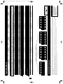 2
2
-
 3
3
-
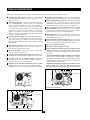 4
4
-
 5
5
-
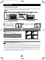 6
6
-
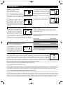 7
7
-
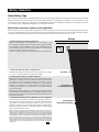 8
8
-
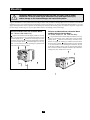 9
9
-
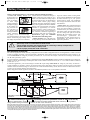 10
10
-
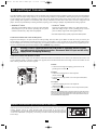 11
11
-
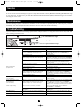 12
12
-
 13
13
-
 14
14
-
 15
15
-
 16
16
-
 17
17
-
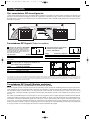 18
18
-
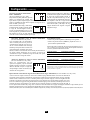 19
19
-
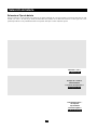 20
20
-
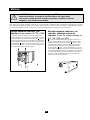 21
21
-
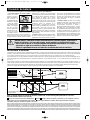 22
22
-
 23
23
-
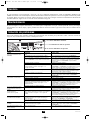 24
24


Tripp Lite APS Series Manual de usuario
- Categoría
- Adaptadores de corriente
- Tipo
- Manual de usuario
- Este manual también es adecuado para
en otros idiomas
- English: Tripp Lite APS Series User manual
Artículos relacionados
-
Tripp Lite Welding System APSX6048VR Manual de usuario
-
Tripp Lite APS Inverters El manual del propietario
-
-
-
-
-
-
-
Tripp Lite TRIPP-LITE PV1000HF PowerVerter DC-to-AC Inverters El manual del propietario
-