Yamaha MGP24X Manual de usuario
- Categoría
- Equipo de música suplementario
- Tipo
- Manual de usuario
Este manual también es adecuado para


MGP32X/MGP24X Owner’s Manual
2
The above warning is located on the rear of the unit.
L’avertissement ci-dessus est situé sur le arrière de l’appareil.
Explanation of Graphical Symbols
Explication des symboles
The lightning flash with arrowhead symbol within an equilateral triangle is intended to alert the user to the presence of uninsulated
“dangerous voltage” within the product’s enclosure that may be of sufficient magnitude to constitute a risk of electric shock to persons.
L’éclair avec une flèche à l’intérieur d’un triangle équilatéral est destiné à attirer l’attention de l’utilisateur sur la présence d’une « ten-
sion dangereuse » non isolée à l’intérieur de l’appareil, pouvant être suffisamment élevée pour constituer un risque d’électrocution.
The exclamation point within an equilateral triangle is intended to alert the user to the presence of important operating and maintenance
(servicing) instructions in the literature accompanying the product.
Le point d’exclamation à l’intérieur d’un triangle équilatéral est destiné à attirer l’attention de l’utilisateur sur la présence d’instructions
importantes sur l’emploi ou la maintenance (réparation) de l’appareil dans la documentation fournie.
IMPORTANT SAFETY
INSTRUCTIONS
1 Read these instructions.
2 Keep these instructions.
3 Heed all warnings.
4 Follow all instructions.
5 Do not use this apparatus near water.
6 Clean only with dry cloth.
7 Do not block any ventilation openings. Install in accordance with
the manufacturer’s instructions.
8 Do not install near any heat sources such as radiators, heat regis-
ters, stoves, or other apparatus (including amplifiers) that produce
heat.
9 Do not defeat the safety purpose of the polarized or grounding-type
plug. A polarized plug has two blades with one wider than the other.
A grounding type plug has two blades and a third grounding prong.
The wide blade or the third prong are provided for your safety. If the
provided plug does not fit into your outlet, consult an electrician for
replacement of the obsolete outlet.
10 Protect the power cord from being walked on or pinched particu-
larly at plugs, convenience receptacles, and the point where they
exit from the apparatus.
11 Only use attachments/accessories specified by the manufacturer.
12 Use only with the cart, stand, tripod, bracket,
or table specified by the manufacturer, or sold
with the apparatus. When a cart is used, use
caution when moving the cart/apparatus com-
bination to avoid injury from tip-over.
13 Unplug this apparatus during lightning storms
or when unused for long periods of time.
14 Refer all servicing to qualified service personnel. Servicing is
required when the apparatus has been damaged in any way, such as
power-supply cord or plug is damaged, liquid has been spilled or
objects have fallen into the apparatus, the apparatus has been
exposed to rain or moisture, does not operate normally, or has been
dropped.
(UL60065_03)
PRÉCAUTIONS CONCER-
NANT LA SÉCURITÉ
1 Lire ces instructions.
2 Conserver ces instructions.
3 Tenir compte de tous les avertissements.
4 Suivre toutes les instructions.
5 Ne pas utiliser ce produit à proximité d’eau.
6 Nettoyer uniquement avec un chiffon propre et sec.
7 Ne pas bloquer les orifices de ventilation. Installer l’appareil confor-
mément aux instructions du fabricant.
8 Ne pas installer l’appareil à proximité d’une source de chaleur
comme un radiateur, une bouche de chaleur, un poêle ou tout autre
appareil (y compris un amplificateur) produisant de la chaleur.
9 Ne pas modifier le système de sécurité de la fiche polarisée ou de la
fiche de terre. Une fiche polarisée dispose de deux broches dont
une est plus large que l’autre. Une fiche de terre dispose de deux
broches et d’une troisième pour le raccordement à la terre. Cette
broche plus large ou cette troisième broche est destinée à assurer
la sécurité de l’utilisateur. Si la fiche équipant l’appareil n’est pas
compatible avec les prises de courant disponibles, faire remplacer
les prises par un électricien.
10 Acheminer les cordons d’alimentation de sorte qu’ils ne soient pas
piétinés ni coincés, en faisant tout spécialement attention aux
fiches, prises de courant et au point de sortie de l’appareil.
11 Utiliser exclusivement les fixations et accessoires spécifiés par le
fabricant.
12 Utiliser exclusivement le chariot, le stand, le
trépied, le support ou la table recommandés
par le fabricant ou vendus avec cet appareil.
Si l’appareil est posé sur un chariot, déplacer
le chariot avec précaution pour éviter tout ris-
que de chute et de blessure.
13 Débrancher l’appareil en cas d’orage ou
lorsqu’il doit rester hors service pendant une période prolongée.
14 Confier toute réparation à un personnel qualifié. Faire réparer
l’appareil s’il a subi tout dommage, par exemple si la fiche ou le cor-
don d’alimentation est endommagé, si du liquide a coulé ou des
objets sont tombés à l’intérieur de l’appareil, si l’appareil a été
exposé à la pluie ou à de l’humidité, si l’appareil ne fonctionne pas
normalement ou est tombé.
(UL60065_03)
WARNING
TO REDUCE THE RISK OF FIRE OR ELECTRIC SHOCK, DO NOT
EXPOSE THIS APPARATUS TO RAIN OR MOISTURE.
AVERTISSEMENT
POUR RÉDUIRE LES RISQUES D’INCENDIE OU DE DÉCHARGE
ÉLECTRIQUE, N’EXPOSEZ PAS CET APPAREIL À LA PLUIE OU À
L’HUMIDITÉ.

MGP32X/MGP24X Owner’s Manual
3
Contents
PRECAUTIONS ...................................... 4
Introduction......................................... 6
Main features .......................................................6
Setup................................................. 7
Preparing the power supply ...............................7
Connections ........................................................7
Powering up the system .....................................7
Getting sound to the speakers...........................7
Setup example.....................................................8
Controls and Connectors ....................... 10
Top panel ...........................................................10
Rear panel..........................................................10
Channel control block ......................................11
Mono input section ....................................................11
Stereo input section...................................................11
Master control block .........................................15
USB device recorder section..................................... 15
iPod/iPhone section................................................... 15
Display section ..........................................................16
Meter section............................................................. 16
FX RTN (effect return) section .................................17
SEND MASTER section............................................ 18
MATRIX section ........................................................18
USB IN/iPod IN section ............................................. 19
PHONES/MONITOR section.....................................19
TALKBACK section ...................................................20
GROUP section.........................................................20
MONO master section...............................................21
STEREO master section ...........................................21
Rear input/output block....................................22
Channel I/O connectors section ................................22
Master I/O connectors section...................................22
Power section............................................................23
Basic Operations and Display.................. 24
Viewing the display...........................................24
Operations of the screen..................................25
Using Effects (FX)................................ 26
Applying effects ................................................26
Detailed effect settings .....................................26
Applying two effects simultaneously ..............27
Displaying FX1 and FX2 together ....................27
Using Graphic EQ ................................. 28
About the graphic EQ (GEQ)........................... 28
Setting the GEQ................................................ 28
Finding and removing feedback ..................... 29
Calling up/saving the GEQ program............... 30
Using the Compressor ........................... 31
About the master compressor ........................ 31
Specifying the compressor settings .............. 31
Calling up/saving the compressor program .. 32
Recording/Playing back ......................... 33
About USB device recording/playing back .... 33
Recording to a USB device.............................. 33
Playing back songs from a USB device ......... 34
Playing back songs from an iPod/iPhone ...... 36
Specifying the recording/playback settings .. 36
Using Other Functions ........................... 37
Applying the Low Pass Filter (LPF) ................ 37
Using the Ducker function............................... 37
Using the Leveler function .............................. 38
Initializing the unit to the factory default
settings (resetting user memory)......... 39
Troubleshooting .................................. 40
Appendix........................................... 42
Message List..................................................... 42
Effect Program List .......................................... 43
Parameter List .................................................. 44
Jack List............................................................ 46
Dimensions....................................................... 47
Specifications................................................... 48
Index.................................................................. 51
Block Diagram and Level Diagram ................. 52

MGP32X/MGP24X Owner’s Manual
4
PRECAUTIONS
PLEASE READ CAREFULLY BEFORE PROCEEDING
* Please keep this manual in a safe place for future reference.
WARNING
Always follow the basic precautions listed below to avoid the possibility of serious injury or even death from
electrical shock, short-circuiting, damages, fire or other hazards. These precautions include, but are not limited to,
the following:
• Do not place the power cord near heat sources such as heaters or radiators,
and do not excessively bend or otherwise damage the cord, place heavy
objects on it, or place it in a position where anyone could walk on, trip over,
or roll anything over it.
• Only use the voltage specified as correct for the device. The required voltage
is printed on the name plate of the device.
• Use only the supplied power cord/plug.
If you intend to use the device in an area other than in the one you purchased,
the included power cord may not be compatible. Please check with your
Yamaha dealer.
• Check the electric plug periodically and remove any dirt or dust which may
have accumulated on it.
• Be sure to connect to an appropriate outlet with a protective grounding
connection. Improper grounding can result in electrical shock.
• This device contains no user-serviceable parts. Do not open the device or
attempt to disassemble the internal parts or modify them in any way. If it
should appear to be malfunctioning, discontinue use immediately and have it
inspected by qualified Yamaha service personnel.
• Do not expose the device to rain, use it near water or in damp or wet
conditions, or place on it any containers (such as vases, bottles or glasses)
containing liquids which might spill into any openings. If any liquid such as
water seeps into the device, turn off the power immediately and unplug the
power cord from the AC outlet. Then have the device inspected by qualified
Yamaha service personnel.
• Never insert or remove an electric plug with wet hands.
• Do not put burning items, such as candles, on the unit. A burning item may
fall over and cause a fire.
• When one of the following problems occur, immediately turn off the power
switch and disconnect the electric plug from the outlet. Then have the device
inspected by Yamaha service personnel.
- The power cord or plug becomes frayed or damaged.
- It emits unusual smells or smoke.
- Some object has been dropped into the instrument.
- There is a sudden loss of sound during use of the device.
• If this device should be dropped or damaged, immediately turn off the power
switch, disconnect the electric plug from the outlet, and have the device
inspected by qualified Yamaha service personnel.
CAUTION
Always follow the basic precautions listed below to avoid the possibility of physical injury to you or others, or
damage to the device or other property. These precautions include, but are not limited to, the following:
• When removing the electric plug from the device or an outlet, always hold the
plug itself and not the cord. Pulling by the cord can damage it.
• Remove the electric plug from the outlet when the device is not to be used for
extended periods of time, or during electrical storms.
• Do not place the device in an unstable position where it might accidentally
fall over.
• Do not block the vents. This device has ventilation holes at the bottom and
sides to prevent the internal temperature from becoming too high. In
particular, do not place the device on its side or upside down. Inadequate
ventilation can result in overheating, possibly causing damage to the
device(s), or even fire.
• Do not place the device in a location where it may come into contact with
corrosive gases or salt air. Doing so may result in malfunction.
• Before moving the device, remove all connected cables.
• When setting up the device, make sure that the AC outlet you are using is
easily accessible. If some trouble or malfunction occurs, immediately turn off
the power switch and disconnect the plug from the outlet. Even when the
power switch is turned off, electricity is still flowing to the product at the
minimum level. When you are not using the product for a long time, make
sure to unplug the power cord from the wall AC outlet.
• Before connecting the device to other devices, turn off the power for all
devices. Before turning the power on or off for all devices, set all volume
levels to minimum.
• Remove the power plug from the AC outlet when cleaning the device.
Power supply/Power cord
Do not open
Water warning
Fire warning
If you notice any abnormality
Power supply/Power cord
Location
Connections
Maintenance
PA_en_1 1/2

MGP32X/MGP24X Owner’s Manual
5
• Do not insert your fingers or hands in any gaps or openings on the device
(vents, ports, etc.).
• Avoid inserting or dropping foreign objects (paper, plastic, metal, etc.) into
any gaps or openings on the device (vents, ports, etc.) If this happens, turn
off the power immediately and unplug the power cord from the AC outlet.
Then have the device inspected by qualified Yamaha service personnel.
• Do not rest your weight on the device or place heavy objects on it, and avoid
use excessive force on the buttons, switches or connectors.
• Do not use speakers or headphones for a long period of time at a high or
uncomfortable volume level, since this can cause permanent hearing loss. If
you experience any hearing loss or ringing in the ears, consult a physician.
Always turn the power off when the device is not in use.
NOTICE
To avoid the possibility of malfunction/damage to the prod-
uct, damage to data, or damage to other property, follow the
notices below.
Handling and Maintenance
• Do not use the device in the vicinity of a TV, radio, stereo
equipment, mobile phone, or other electric devices. Oth-
erwise, the device, TV, or radio may generate noise.
• Do not expose the device to excessive dust or vibrations,
or extreme cold or heat (such as in direct sunlight, near a
heater, or in a car during the day) to prevent the possibility
of panel disfiguration, damage to the internal components
or unstable operation.
• Do not place vinyl, plastic or rubber objects on the device,
since this might discolor the panel of this device.
• When cleaning the device, use a dry and soft cloth. Do
not use paint thinners, solvents, cleaning fluids, or chemi-
cal-impregnated wiping cloths.
• Condensation can occur in the device due to rapid, dras-
tic changes in ambient temperature—when the device is
moved from one location to another, or air conditioning is
turned on or off, for example. Using the device while con-
densation is present can cause damage. If there is reason
to believe that condensation might have occurred, leave
the device for several hours without turning on the power
until the condensation has completely dried out.
• Avoid setting all equalizer controls and faders to their
maximum. Depending on the condition of the connected
devices, doing so may cause feedback and may damage
the speakers.
• Do not apply oil, grease, or contact cleaner to the faders.
Doing so may cause problems with electrical contact or
fader motion.
• When turning on the AC power in your audio system,
always turn on the power amplifier LAST, to avoid speaker
damage. When turning the power off, the power amplifier
should be turned off FIRST for the same reason.
Saving data
• To protect against data loss due to media damage, we
recommend that important data that has been saved via
the USB device recorder to a USB device should also be
saved to your computer or an external USB device.
Connectors
XLR-type connectors are wired as follows (IEC60268 stan-
dard): pin 1: ground, pin 2: hot (+), and pin 3: cold (-).
Insert TRS phone jacks are wired as follows: sleeve:
ground, tip: send, and ring: return.
Information
About copyrights
• Copying of the commercially available musical data including but
not limited to MIDI data and/or audio data is strictly prohibited
except for your personal use.
About this manual
• The illustrations and LCD screens as shown in this manual are
for instructional purposes only, and may appear somewhat differ-
ent from those on your device.
• Throughout this manual, all panel illustrations show the panel of
the MGP32X.
• The company names and product names in this manual are the
trademarks or registered trademarks of their respective compa-
nies.
iPod
TM
, iPhone
TM
iPhone, iPod, iPod classic, iPod nano, and iPod touch are
trademarks of Apple Inc., registered in the U.S. and other
countries.
“Made for iPod” and “Made for iPhone” mean that an elec-
tronic accessory has been designed to connect specifically
to iPod or iPhone respectively, and has been certified by the
developer to meet Apple performance standards. Apple is
not responsible for the operation of this device or its compli-
ance with safety and regulatory standards. Please note that
the use of this accessory with iPod or iPhone may affect
wireless performance.
Handling caution
Yamaha cannot be held responsible for damage caused by improper use
or modifications to the device, or data that is lost or destroyed.
PA_en_1 2/2

MGP32X/MGP24X Owner’s Manual
6
Introduction
Main features
D-PRE (Discrete Class-A MIC preamp)
Mono input channels are equipped with Class-A discrete micro-
phone preamplifiers. The head amplifier features an inverted Dar-
lington circuit* used in high-end audio devices, and reproduces
low frequencies with exceptionally musical characteristics as
well as sustained high frequencies. Independent toggle switching
of +48V phantom power and 26dB (pad) on each channel.
* Inverted Darlington circuit: An amplifying method for elimi-
nating the nonlinear characteristics of the amplifier element
and suppressing the distortion. The circuit features highly
musical phase characteristics.
X-pressive EQ
The shelving EQ (low/high) on the mono input channels features
Xpressive EQ, which effectively models analog EQ utilizing
Yamaha’s famed VCM (Virtual Circuitry Modeling) technology.
We analyzed vintage EQ analog circuits and redesigned the tech-
nology specifically for the MGP to create an EQ with exception-
ally musical characteristics. Furthermore, the cutoff frequency
can also be adjusted, enhancing use of the EQ in sound reinforce-
ment applications, and extending the sonic control range of the
mixer.
USB device recorder
A USB device recorder is built into the mixer for recording mixed
audio to a USB device as an audio file, and for playing back
music saved in the USB device by assigning it to the desired
channel output or bus output. Supported file formats are MP3
(MPEG-1 Audio Layer-3) and WAV for recording and MP3,
WAV, and AAC for playback.
Stereo master – COMP and GEQ
The stereo master is equipped with a compressor (COMP) or
multiband compressor that adjusts the sound pressure of the out-
put signal, and with a graphic equalizer (GEQ) that adjusts sound
quality such as feedback.
Digital effects — REV-X and SPX
Two powerful digital effect blocks are built into the mixer: REV-
X (8 types) and SPX (16 types). REV-X gives you a high-density,
richly reverberant sound ambience, with smooth attenuation,
spread and depth that work together to enhance the original
sound. The versatile SPX block features a variety of effect appli-
cations, such as reverb, delay, and modulation effects, along with
complex combinations of multiple effects.
Convenient, practical functions for events –
Ducker, Leveler, and Stereo Image
The mixer features three exceptionally convenient features for the
stereo input channels: Ducker, Leveler and Stereo Image. The
ducker function automatically lowers the level of background
music to accommodate the voice of an announcer coming in on
another channel. The leveler function automatically maintains a
consistent sound volume, even when using sound sources that
have different mastering levels. Stereo image narrows the pan
balance of the stereo sound source, and changes stereo signals to
mono. This is useful in restaurants and other spaces where the left
and right speakers are distantly positioned, or when you input
accompaniment sound to the left channel and vocal sound to the
right and want a more natural stereo image.
USB port for playing and charging your iPod/
iPhone
Digital audio output from the iPod/iPhone can be directly input to
the unit, and the iPod/iPhone can be charged while connected.
About the models
The MGP32X and MGP24X feature a different number of mon-
aural input channels and COMP control knobs. The MGP32X has
24 monaural input channels and the MGP24X has 16. The
MGP32X is equipped with 16 COMP control knobs for channels
9-24 and the MGP24X with 8 COMP control knobs for channels
9-16.
Conventions in this manual
• Whenever there is a different number of channels or a different
channel number for the same function between the MGP32X
and the MGP24X, the number that applies only to the MGP24X
model is enclosed in curly brackets { }. For example, “CH1-24
{CH1-16}” means channels 1-24 for the MGP32X and chan-
nels 1-16 for the MGP24X.
* “CH” is an abbreviation for channel.
• Control knobs on the panel are called “knobs.” Some knobs
rotate from a minimum value to a maximum value, while others
rotate endlessly.
MGP Editor
MGP Editor is a free software application that gives you addi-
tional control of your MGP mixer’s DSP settings via your iPhone,
iPod touch, and iPad. See the following web site to download the
application.
http://www.yamahaproaudio.com/global/en/products/periph-
erals/applications/mgp_editor/
Included Accessories
• AC Power Cord
• Owner’s manual (this book)
Thank you for purchasing the Yamaha MGP32X/MGP24X
mixing console.
Please read this manual thoroughly to make the best use of
the mixing console for the longest possible period of time.
After reading this manual, please keep it available for future
reference.

MGP32X/MGP24X Owner’s Manual
7
Setup
Preparing the power supply
1. Make sure that the power switch of the unit is
set to the “ ” position (off).
2. Connect the socket of the included power cord
to the [AC IN] connector.
3. Plug the power cord into a power outlet.
CAUTION
• Unplug the power cord from the outlet when not using the
mixer or during electrical storms.
Connections
1. Turn all the faders and GAIN knobs completely
down.
2. Connect speakers, microphones and/or instru-
ments.
Refer to “Setup example” on pages 8-9 for more information
on connections.
Powering up the system
To prevent an unwanted burst of noise from the
speakers, power up the devices in the following
order: peripheral devices (instrument, micro-
phone, iPod) MGP mixer power amps (or
powered speakers).
Reverse this order when turning the power off.
CAUTION
• Be sure to turn the power on/off in this order every time you
use the mixer. Failure to do so may result in loud noise
bursts that can damage your equipment, your ears, or both.
Getting sound to the speakers
1. While producing sound on your instrument or
microphone, adjust the channel GAIN knobs
so that the corresponding peak indicators
flash briefly at the highest peak levels.
NOTE
• To use the level meter to get a more accurate reading of the
incoming signal level, turn on the channel PFL switch. Adjust
the GAIN knobs so that the PFL/AFL level meter indicator
only occasionally rises above the “0” level.
• The gain (volume) level of the audio files in the USB device
may be too high. Refer to the NOTE on page 35 to adjust the
volume.
• Note that the PHONES jack or MONITOR OUT jacks output
the pre-fader signal from all channels for which the PFL
switch is ON, so that those signals can be monitored.
2. Turn on ( ) the ON and ST (Stereo) switches
for each channel you are using.
3. Make sure that all the PFL and AFL switches
are off ( ).
4. Turn on ( ) the ON switch of the STEREO
master.
5. Raise the STEREO master fader to the 0 dB
position.
6. Adjust the volume of each channel by moving
its fader up and down.
7. Adjust the overall volume with the STEREO
master fader.
The overall headphone level is adjusted with the PHONES
knob.
NOTE
If the PEAK indicator lights frequently, slowly lower the channel
faders a little to avoid distortion.
GAIN knobs Power switch (rear panel)
Faders
1 GAIN knob
6 Fader
2 ON switch
1 PEAK
indicator
2 ST switch
Channel
STEREO master
3 PFL switches
AFL switches
5 STEREO
master fader
4 ON switch
1, 7
Level meter
3
AFL switches

Setup
MGP32X/MGP24X Owner’s Manual
8
Microphones for
talkback
DVD player (voice)
Computer/Audio interface
DJ mixer
Synthesizer
Power amp
Powered speakers
Microphone
CH24 {CH16} (for MC)
Setup example
Lamp
(Yamaha LA-1L)
CD player
Powered monitor
speakers
Foyer etc.
Stage
Speakers
Powered monitor speakers
(For musician monitoring)
Powered
subwoofer

MGP32X/MGP24X Owner’s Manual
9
Setup
USB device
iPod/iPhone
Headphones
Compressor
Instrument, Microphone
Microphone
x 8
Drum
Bass
Rear panel
*The illustrations show the
panel of the MGP32X.
Top panel
CAUTION
• When using a condenser
microphone, set the +48V
phantom switch to ON
(page 11).
* If electric guitars and basses can be con-
nected directly to the mixer’s inputs, use a
DI box (direct box) or amp simulator
between the instrument and the mixer.

MGP32X/MGP24X Owner’s Manual
10
Controls and Connectors
Top panel
Mono input section
(page 11)
Stereo input section
(page 11)
USB device recorder section (page 15)
Display section (page 16)
iPod/iPhone section (page 15)
Meter section (page 16)
SEND MASTER
section (page 18)
MATRIX section
(page 18)
USB IN/iPod IN section
(page 19)
PHONES/MONITOR
section (page 19)
TALKBACK section
(page 20)
STEREO master section (page 21)
MONO master section (page 21)
GROUP section (page 20)
FX RTN (effect return) section (page 17)
Channel I/O connectors section (page 22)
Master I/O connectors section (page 22)
Power section (page 23)
Rear panel
Channel Control Block (input) Master Control Block (output)

MGP32X/MGP24X Owner’s Manual
11
Controls and Connectors
Channel control block
Mono input section
Stereo input section
q 26dB (PAD) switch
Turning this switch on ( ) attenuates the input signal from
the INPUT jack of the mono channel by 26dB. Turn this
switch off ( ) if you have connected a microphone or other
device with a low input level to the channel. Turn it on ( )
if you have connected a line-level device.
w +48V switch and indicator
Toggles phantom power on and off. When this switch is
turned on ( ), the mixer supplies DC +48V power to
INPUT A of XLR input jacks. Turn this switch on when
using one or more phantom-powered condenser microphones.
The indicator is on when the switch is on.
CAUTION
• Be sure to leave this switch off ( ) if you do not need
phantom power.
• When turning phantom power on ( ), follow the impor-
tant precautions below, in order to prevent noise and
possible damage to the mixer and external devices.
• Turn this switch off when connecting a device that
does not support phantom power to INPUT A of XLR
input jacks
• Do not connect/disconnect a cable to/from channels 1-
24 {1-16} while this switch on.
• Turn the mixer’s output controls – STEREO master and
GROUP faders- all the way down when turning phan-
tom power on/off.
e GAIN knob
Adjusts the sensitivity of the input signal. Monaural channels
have a 26dB switch (q) that lets you change the range of this
control. The adjustable sensitivity range is as follows.
Mono channel
NOTE
The stereo channel is fixed to a range of -34dB to +10dB.
r (High Pass Filter) switch
Turning this switch on ( ) will apply a high-pass filter that
attenuates frequencies below 100Hz in the signal by a slope
of 12dB/octave.
t
COMP knobs and indicator (Channel 9-24 {9-16})
Adjusts the amount of compression applied to the channel.
As the knob is turned to the right the compression ratio
increases while the output gain is automatically adjusted
accordingly. The result is smoother, more even dynamics
because louder signals are attenuated while the overall level
is boosted. The COMP indicator comes on when the com-
pressor operates.
NOTE
Avoid setting the compression too high, as the higher average
output level that results may lead to feedback.
Continue to next page
Mono channels
1–24 (MGP32X)
1–16 (MGP24X)
Stereo channels
25–32 (MGP32X)
17–24 (MGP24X)
* y-!0 are for CH29/
30, CH31/32 {CH21/
22,CH23/24} only.
Channel number
Channel number
26dB switch Range
ON -34dB to +10dB
OFF -60dB to -16dB

Controls and Connectors
MGP32X/MGP24X Owner’s Manual
12
y DUCKER SOURCE indicator
The indicator of the selected input source (CH24 {CH16} or
GROUP1) comes on. The input source can be selected on the
display (page 37).
u DUCKER switch
Turning this switch on ( ) lowers the volume of the stereo
channel automatically when a signal exceeding a certain level
is input to the input source (CH24 {CH16} or GROUP1).
When the switch is turned on, the switch’s lamp comes on.
i LEVELER switch and indicator
Turning this switch on ( ) allows the volume to be
adjusted automatically to a certain level, when the actual
sound output level differs for each song. The indicator is on
when the switch is on.
o Input select switch
Selects the input signal source. If this switch is set to ANA-
LOG( ), the jacks for CH29/30 and 31/32 {CH21/22, 23/
24} will be the input source. If this switch is set to USB IN
( ) or iPod IN ( ), the signal from an USB device or
iPod/iPhone will be the input source. The signal from an USB
device will be input to CH29/30 {21/22}, while the signal
from an iPod/iPhone will be input to CH31/32 {23/24}.
NOTE
The GAIN knobs do not affect the volume of your iPod/iPhone.
To adjust the pre-channel-fader signal volume, refer to page
36.
!0 STEREO IMAGE switch
Selects the type of output signal for the input stereo signal.
• MONO : Mono signal
• BLEND : Stereo signal in which left and right inputs
are mixed at a certain percentage for a more nat-
ural stereo image, and in which the pan is con-
trolled.
• STEREO : Stereo signal (original, as is)
!1 Equalizer knobs (HIGH, MID, and LOW)
This three-band equalizer changes the tone of the high, mid,
and low frequency bands. Turning the knob to the right boosts
the corresponding frequency band, while turning to the left
attenuates the band. Setting the knob to the “t” position pro-
duces a flat response in the corresponding band. The upper
knob sets the center frequency for the mid range, while the
lower knob sets the amount of attenuation or boost (counter-
clockwise/clockwise) for the range. For the CH25/26 and
CH27/28 {CH17/18 and CH19/20}, the attenuation/boost can
only be set at a fixed 2.5kHz center frequency. The following
table shows the EQ type, frequency, and cut/boost range for
each of the three bands.
* The MID frequency can be adjusted from 250Hz to 5kHz.
The MID frequency is 2.5kHz when the MID frequency
control is set at the center position.
Mono channels
1–24 (MGP32X)
1–16 (MGP24X)
Stereo channels
25–32 (MGP32X)
17–24 (MGP24X)
* y-!0 are for CH29/
30, CH31/32 {CH21/
22,CH23/24} only.
Channel number
Channel number
Band Type Frequency
Cut/Boost
range
HIGH Shelving 8kHz
±15dBMID Peaking 2.5kHz*
LOW Shelving 125Hz

MGP32X/MGP24X Owner’s Manual
13
Controls and Connectors
!2 AUX knobs (1-4)
These knobs adjust the channel’s signal levels into AUX
buses 1 to 4. Each knob controls the signal into the corre-
sponding AUX bus. On stereo channels, the LINE L (odd)
and LINE R (even) input signals are mixed before moving
into the AUX bus. These knobs should generally be set close
to the “t” (nominal) position.
NOTE
• To enable use of AUX5 and AUX6, you must turn on ( )
the AUX5/AUX6 switch (!5).
• For AUX1 to AUX4, you use the PRE switch (!3) to select
whether the pre-fader or post-fader signal is sent to the bus.
For AUX5 and AUX6, only the post-fader signal can be sent.
!3 PRE switch
Selects whether the pre-fader or the post-fader signal is fed to
the corresponding pair of AUX 1-4 buses. AUX1 and 2 and
also AUX3 and 4 should be paired. The upper PRE switch
controls the signal to AUX1 and AUX2; the lower switch
controls the signal to AUX3 and AUX4. If the switch is on
( ), the mixer feeds the pre-fader signal to the correspond-
ing buses. If off ( ), the mixer feeds the post-fader signal.
!4 FX (effect) knobs (1, 2)
These knobs adjust the channel’s post-fader signal levels into
FX buses 1 and 2. On stereo channels, the LINE L (odd) and
LINE R (even) input signals are mixed before moving into
the FX bus. These knobs should generally be set close to the
“t” (nominal) position.
NOTE
If the AUX5/AUX6 switch is on, these knobs adjust the output
to the AUX5 and AUX6 buses.
!5 AUX5, AUX6 switch
Selects whether the channel’s post-fader signal is sent to
AUX buses 5 and 6 or FX buses l and 2. If the switch is on
( ), the signal goes to AUX5 and 6 buses; if off ( ), the
signal goes to the FX buses.
!6 PAN knob (Mono channels)
BAL knob (Stereo channels)
These knobs set the stereo pan position and determine the
volume balance between left and right. When the channels
are panned hard left or hard right, sound is heard from only
the hard-panned channel.
The PAN knob determines each mono signal’s pan position-
ing between left and right, while the BAL knob determines
the stereo channel’s volume balance between left and right.
!7 ON switches
Turning this switch on ( ) sends that channel’s signal to
the buses. When the switch is turned on, the switch’s lamp
comes on. If you turn the switch off ( ), all of the signal
sent to the buses such as AUX and GROUP buses is cut off.
NOTE
• The ON switch does not affect the operation of the PFL
switch (@1). You can monitor the channel’s pre-fader signal
through the PHONES jack even when the ON switch is off.
• To reduce noise, turn all unused channels off.
!8 PEAK indicator
Lights red when the channel’s post-equalizer signal level
reaches 3 dB before clipping.
!9 SIG (Signal) indicator
Lights green when a signal is being input to the channel.
@0 Bus assign switches
These switches determine the bus(es) to which each channel’s
signal is sent. Press the switch in ( ) to output the signal to
the corresponding bus.
• Switches 1-2, 3-4: Assign the channel’s signal to the
GROUP 1 to 4 buses.
• ST switch: Assigns the channel’s signal to the STE-
REO L and R buses.
NOTE
To send the signal to each bus, engage the ON switch (!7).
@1 PFL (Pre-Fader Listen) switch and indicator
When the PFL switch is turned on ( ) the indicator comes
on and the channel pre-fader signal is output to the MONI-
TOR OUT and PHONES jacks for monitoring.
@2 Channel fader
Adjusts the output level of the input channel signal. Use these
faders to adjust the balance between the various channels.
NOTE
To reduce noise, set the fader sliders for any unused channels
all the way down.

Controls and Connectors
MGP32X/MGP24X Owner’s Manual
14
AUX1
AUX2
ST
1–2
3–4
AUX3
AUX4
Mono Channel
Stereo Channel

MGP32X/MGP24X Owner’s Manual
15
Controls and Connectors
Master control block
USB device recorder section
With this section you can connect a USB device to record and
play back music. (page 33)
q USB IN connector
Connects the USB device.
w USB ACCESS indicator
Lights while the unit accesses the USB device.
Transport section
e REW button
Press to move to the previous song. Holding down this button
while playing back rewinds the song.
r PLAY button and indicator
Press to alternately start/pause playback of the song. The
indicator lights during playback, and flashes while paused.
t FWD button
Press to move to the next song. Holding down this button
while playing back forwards the song. Pressing this button
while recording stops the current recording and begins
recording a new file.
y REC button and indicator
Press to start/stop recording. The indicator lights while
recording.
iPod/iPhone section
This section lets you connect an iPod/iPhone to play back a song
(page 36) and charge the iPod/iPhone. The unit charges the iPod/
iPhone while it is connected to and recognized by the unit.
q iPod/iPhone IN connector
Use an USB cable to connect an iPod/iPhone.
w iPod indicator
Lights when the unit is accessing an iPod/iPhone.
CAUTION
• Use the genuine Apple Dock Connector USB Cable for
the iPod/iPhone connection.
• When connecting to an iPod/iPhone, allow at least 6 sec-
onds to pass between turning the mixer on and off and
plugging or unplugging the USB cable.
• Please do not use a USB hub.
• The unit’s iPod/iPhone IN connector is dedicated to
iPod/iPhone use only. Please do not connect other USB
devices.
NOTE
If you connect an iPhone, incoming calls or emails may cause
a notification sound to be output. In order to prevent this, we
recommend setting the iPhone’s Airplane mode to “on.”
Capacity and format of the USB device
Up to 64GB of the capacity for the USB device is guaranteed
by Yamaha. (However, Yamaha cannot guarantee operation
for all the USB devices). The supported file system is FAT32.
The maximum size of one file is 2GB.
NOTICE
• While the unit is accessing data (such as during
recording, playing back, and saving operations), do
NOT remove the USB device from the USB IN con-
nector, and do NOT turn off the unit. Doing so may
damage the USB device or corrupt the data on either
or both the unit and the USB device.
• Make sure that you insert the USB device all the way
in the correct orientation or upside down. Avoid
inserting with excessive force.
ert y
Transport
section

Controls and Connectors
MGP32X/MGP24X Owner’s Manual
16
Display section
This section is for setting and operating the display. Refer to
pages 24-25 for details.
q Display
Indicates the various messages and settings related to the cur-
rently selected operation or function.
w Knob 1, Knob 2
Selects/sets the functions and parameters appearing on the
display. Rotate Knob 1 to operate the functions on the lower
left side of the display, and Knob 2 for the functions on the
lower right side of the display.
e HOME button
Calls up the display to view the status of the functions. This
button does not determine or change the parameter.
r FX1 and FX2 buttons
Call up the display to switch the programs of FX1 (effect1)
and FX2 (effect2) and to adjust their parameters.
t GEQ button
Calls up the display to set the Graphic equalizer (GEQ).
y COMP button
Calls up the display to set the compressor.
u USB button
Calls up the display to record and play back with the USB
device.
i SETUP button
Calls up the display to adjust the contrast of the display, and
to set the ducker and the leveler.
Meter section
Use these meters to view various signal levels: the levels to the
STEREO OUT L/R jacks, the PFL and AFL levels, and the levels
to the GROUP OUT 1-4 jacks. The PFL or AFL signals indicated
by these meters can be monitored through the MONITOR OUT
jacks and the PHONES jack.
q METER SELECT button and indicator
Switches the display of the level meter to the output signal
level of the STEREO OUT L/R and the PHONES jacks, or of
the GROUP OUT 1-4 jacks. The indicators for the selected
signals come on.
w STEREO level meter
Shows the signal level output to the STEREO OUT L/R jacks
or the GROUP OUT 1 and 2 jacks, respectively. The “0”
position corresponds to the standard level. The PEAK indica-
tor lights red when the level hits the clipping point.
e PFL/AFL level meter
Shows the signal level output to the PHONES jack or the
GROUP OUT 3 and 4 jacks, respectively. The “0” position
corresponds to the standard level. The PEAK indicator lights
red when the level hits the clipping point.
NOTE
The PFL signal has display priority over the AFL signal when
an input channel’s PFL switch is on.
Knob 1 Knob 2

MGP32X/MGP24X Owner’s Manual
17
Controls and Connectors
FX RTN (effect return) section
This section sets the effect returns (FX1 and FX2) on/off, and
determines the level of the effect signal and to which bus the sig-
nal is sent.
q AUX (PRE) knobs (1-4)
These knobs adjust the level of the effect sent to the AUX1 to
AUX4 buses.
w FX TO FX BLEND knob
Sends the signal from FX1 to FX2 and from FX2 to FX1.
Rotate this knob from the center “OFF” position to the right to
adjust the send level from FX1 to FX2, and to the left to adjust
the send level from FX2 to FX1. Only the pre-fader signal can
be sent.
e TAP button and indicator
This feature lets you set the delay time for FX2 by tapping on
the button. This feature only works when the effect type for
FX2 is set to “, DELAY” or “. SINGLE DELAY.” To set
the delay time, tap on the button at the appropriate interval.
The average interval at which you tap the button will be cal-
culated, and that value will be set for the delay time. Continue
tapping as necessary until you get the timing right.
The TAP indicator flashes in sync with the delay time when
, DELAY or . SINGLE DELAY is selected.
NOTE
• Adjust the average interval within range of the variable delay
time.
• See page 44 for the range of the variable delay time.
r ON switch
Turn this switch on
()
to enable the FX RTN (effect
return). When the switch is turned on, the switch’s lamp comes
on.
t SIG (Signal) indicator
Lights when an effect signal is input into the channel.
y Bus assign switches
These switches determine the bus(es) to which the signal of the
internal digital effects is sent. Press the switch in
()
to out-
put the signal to the corresponding buses.
• Switches 1-2, 3-4: Assign to the GROUP1 to
GROUP4 buses.
• ST switch: Assigns to the STEREO L/R bus.
u PFL (Pre-Fader Listen) switch and indicator
When the PFL switch is turned on
()
, the indicator will
light and the pre-FX (1, 2) RTN-fader signal is output to the
MONITOR OUT and PHONES jacks for monitoring.
i FX RTN (effect return) faders (1, 2)
These adjust the level of the effect sent from the internal effect
to the GROUP1 to GROUP4 buses, and STEREO L/R buses.
First tap Second tap Third tap Fourth tap
ab c
The average interval will be set (the average of a, b, and c)

Controls and Connectors
MGP32X/MGP24X Owner’s Manual
18
SEND MASTER section
This section adjusts the levels and controls the output of signals
from the six AUX buses. Each of these signals outputs to the cor-
responding SEND (AUX1-AUX6) jack respectively.
q AUX knobs (1-6)
These knobs adjust the level of the signal from the indicated
AUX1 to AUX6 buses into the corresponding SEND (AUX1 to
AUX6) jacks. The
“t”
position of the knob is the nominal
level (0 dB).
w AFL (After-Fader Listen) switch and indicator
Turning this switch on monitors the post-AUX1 to AUX6 knob
(q)
signals that output to the MONITOR OUT and PHONES
jacks for monitoring.
NOTE
• The PFL signal has priority when both the PFL switch and
AFL switch are on. To monitor the post-fader signal, make
sure to turn off all PFL switches.
• If the PFL (preferred) is enabled, the AFL indicator does not
light, even if the AFL switch is pressed.
MATRIX section
This section adjusts the levels and controls the output of signals
to the MATRIX OUT jacks from GROUP OUT and STEREO
OUT. The signals from the MATRIX 1 and 2 buses are sent to the
MATRIX 1 and 2 jacks respectively.
q GROUP knobs (1-4)
These knobs adjust the level of the signals sent from GROUP
OUT 1-4 buses to the MATRIX OUT jacks.
w STEREO knobs (L, R)
These knobs adjust the level of the signals sent from STEREO
OUT L/R buses to the MATRIX OUT jacks.
e MATRIX master knobs (1, 2)
These knobs adjust the overall level of the signal output to the
MATRIX OUT jacks.
NOTE
The “t” positions of the knobs for (q), (w),and (e) indicate
the nominal level (0 dB).
r AFL switch and indicator
When the AFL switch is on, the indicator will light and the sig-
nal after the MATRIX master knob is output to the PHONES
and MONITOR OUT jacks for monitoring.

MGP32X/MGP24X Owner’s Manual
19
Controls and Connectors
USB IN/iPod IN section
This section determines the destination of the signal output from
the connected USB device or iPod/iPhone, and adjusts the signal
level.
q USB IN knob
Adjusts the playback level from the connected USB device.
w TO STEREO/TO MONITOR switch
Determines the destination of the signal output from the con-
nected USB device.
• TO STEREO ( ): Sends to the STEREO L/R bus.
• TO MONITOR ( ): Sends to the MONITOR OUT
jacks and PHONES jack.
e iPod IN knob
Adjusts the playback level from the connected iPod/iPhone.
r TO STEREO/TO MONITOR switch
Determines the destination of the signal output from the con-
nected iPod/iPhone.
• TO STEREO ( ): Sends to the STEREO L/R bus.
• TO MONITOR ( ): Sends to the MONITOR OUT
jacks and PHONES jack.
NOTE
CH29/30, 31/32 {CH21/22,23/24} can be selected as the desti-
nations of the signal input from the connected USB device or
iPod/iPhone (pages 34, 36).
PHONES/MONITOR section
You connect a pair of headphones and adjust the output signal
level to the PHONES and MONITOR OUT jacks.
q PHONES jack
Connect a pair of headphones to this TRS phone jack. The
PHONES jack outputs the same signal as the MONITOR OUT
jacks.
w PHONES knob
Adjusts the level of the signal output to the PHONES jack.
e MONITOR knob
Adjusts the level of the signal output to the MONITOR OUT
jacks.
NOTE
If you want to monitor the output signal from the STEREO,
MONO or GROUP bus, turn on the AFL switch of each respec-
tive bus.

Controls and Connectors
MGP32X/MGP24X Owner’s Manual
20
TALKBACK section
Use the talkback function to send instructions mainly from the
operator to musicians and studio staff. This section adjusts the
level of the microphone signal received from the TALKBACK
MIC IN jack, and determines the bus to be output.
q Talkback knob
Adjusts the talkback level.
w AUX1-4 switch and indicator
Turning this switch on sends the signal from the TALKBACK
MIC IN jack to the AUX1 to AUX4 buses.
e STEREO switch and indicator
Turning this switch on sends the signal from the TALKBACK
MIC IN jack to the STEREO L/R bus.
GROUP section
This section adjusts the level and controls the flow of the signals
from the four GROUP buses. While the signal from each GROUP
bus is always sent to the corresponding GROUP OUT jack, you
are also free to use the ST and AFL switches to selectively send
these groups to the STEREO and AFL buses.
q PAN knob
Determines how the signal from the GROUP 1-4 buses is posi-
tioned on the STEREO L/R buses when turning the ON switch
(w)
on.
w ON switch
Turning this switch on enables the GROUP fader. When the
switch is turned on, the switch’s lamp comes on.
e ST (Stereo) switch
Turning this switch on sends the signal adjusted with the
GROUP fader
(t)
via the PAN knob
(q)
to the STEREO L/R
bus.
r AFL (After-Fader Listen) switch and indictor
When the AFL switch is on, the indicator will light and the sig-
nal after the GROUP fader
(t)
is output to the MONITOR
OUT and PHONES jacks for monitoring.
t GROUP faders (1-4)
These adjust the level of the signal sent to the corresponding
GROUP OUT 1-4 jacks.
NOTE
• The PFL signal has priority when both the PFL switch and
AFL switch are on. To monitor the post-fader signal, make
sure to turn off all PFL switches.
• If the PFL (preferred) is enabled, the AFL indicator does not
light, even if the AFL switch is pressed.

MGP32X/MGP24X Owner’s Manual
21
Controls and Connectors
MONO master section
This section adjusts the level of the mixed monaural output from
the STEREO bus.
q ON switch
Turning this switch on enables the MONO master fader. When
the switch is turned on, the switch’s lamp comes on.
w LPF indicator
Lights when setting “LPF ON” to “ON” in the SETUP screen
on the display.
e AFL switch and indicator
When the AFL switch is turned on, the indicator will light and
the signal after the MONO master fader is output to the MON-
ITOR OUT and PHONES jacks for monitoring. To monitor the
post-fader signal, make sure to turn off all PFL switches.
r MONO master fader
Adjusts the level of the signal output in mono from the STE-
REO bus to the MONO OUT jack.
STEREO master section
This section adjusts the level of the main output from the STE-
REO bus.
q ON switch
Turning this switch on enables the STEREO master fader.
When the switch is turned on, the switch’s lamp comes on.
w COMP (Compressor) indicator
Lights when setting the COMP to “ON” in the COMP screen
on the display.
e GEQ indicator
Lights when setting the GEQ ON to “ON” in the GEQ screen
on the display.
r AFL switch and indicator
When the AFL switch is on, the indicator will light and the sig-
nal after the STEREO master fader is output to the MONITOR
OUT and PHONES jacks for monitoring. To monitor the post-
fader signal, make sure to turn off all PFL switches.
t STEREO master fader
Adjusts the level of the signal output from the STEREO bus to
the STEREO OUT jack.

Controls and Connectors
MGP32X/MGP24X Owner’s Manual
22
Rear input/output block
Channel I/O connectors section
q Mono inputs
• INPUT A: These are balanced XLR-3-31 type input
jacks (1: Ground; 2: Hot; 3: Cold).
• INPUT B: These are TRS phone-jack type balanced
inputs. You can connect either balanced or unbal-
anced phone plugs to these jacks.
NOTE
On any given channel, you may use either an XLR or phone
jack, but not both.
• INSERT: These are unbalanced TRS (tip=send/out;,
ring=return/in; sleeve=ground) phone-type bidi-
rectional jacks. You can use these jacks to con-
nect channels to devices such as graphic
equalizers, compressors, and noise filters.
NOTE
Connection to an INSERT jack requires a special insertion
cable as illustrated below. Use a separately-sold Yamaha inser-
tion cable (YIC025/050/070).
w Stereo inputs
• LINE: These are stereo input jacks that connect line-
level instruments, such as a CD player. These are
unbalanced phone-jack and RCA pin-jack line
inputs.
NOTE
On any given channel, you may use either a phone or RCA pin
jack, but not both.
Master I/O connectors section
e MATRIX OUT (1, 2)
These are impedance-balanced (*) TRS phone jacks. These
jacks output the signal adjusted by the knobs in the MATRIX
section.
r MONITOR OUT (L, R)
These are impedance-balanced(*) TRS phone output jacks
that you connect to your monitor system. These jacks output
the signal before or after the faders for the various buses. The
PFL and AFL indicators in each section indicate which signal
is being output.
NOTE
The PFL switch has priority when both the PFL switch and AFL
switch are on. To monitor the post-fader signal, make sure to
turn off all PFL switches.
CH25/26-31/32
{CH17/18-23/24}
CH1-24 {CH1-16}
Master I/O connectors section
Power section
Channel I/O connectors section
To the INSERT jack
Sleeve (ground)
Ring: IN
Tip: OUT
To the input jack
of the external
processor
To the output jack
of the external
processor
Tip: OUT
Tip: IN
* Impedance balanced
Since the hot and cold terminals of impedance balanced
output jacks have the same impedance, these output jacks
are less affected by induced noise.

MGP32X/MGP24X Owner’s Manual
23
Controls and Connectors
t Screw holes
These are screw holes for mounting a stand for various
devices (87mm between the holes). Stands and screws are not
included with this product, and must be provided by the user.
Use M5 screws that are no longer than 20mm.
y STEREO INSERT (L, R)
These are unbalanced TRS (tip=send/out; ring=return/in;
sleeve=ground) bidirectional jacks. You can use these jacks to
connect a graphic equalizer or other signal processor. Con-
necting an INSERT jack requires a special insertion cable.
Refer to the NOTE for INSERT in
“
Mono inputs
”
(page 22).
u TALKBACK MIC IN
This is an XLR-3-31 type unbalanced input jack for connect-
ing a talkback microphone.
i LAMP
This is an XLR-4-31 connector that supplies power to a sepa-
rately sold gooseneck lamp (the Yamaha LA1L is recom-
mended).
NOTE
If you connect a lamp with different connectors or you short-cir-
cuit it by mistake, the protective circuit that powers off only the
LAMP power supply will be triggered. To recover the LAMP
power supply, turn the unit off, and wait for about 10 seconds
before turning it on again.
o GROUP OUT (1-4)
These impedance-balanced (*) TRS jacks output the GROUP
1-4 signals. Use these jacks to connect to the inputs of a
multi-track recorder, external mixer, or similar device.
!0 STEREO OUT (L, R)
These are balanced XLR and TRS output jacks that output the
mixed stereo signal. They output the signal adjusted by the
STEREO master fader. Connect these jacks to the power
amplifier that drive your main speakers.
!1 MONO OUT
This is a balanced XLR-3-32 output jack that outputs the sig-
nal adjusted by the MONO master fader. This outputs a mono
signal of the mixed stereo bus (L/R). Connect to a subwoofer
speaker or an expanded SR system.
!2 SEND (AUX1-AUX6)
These are balanced XLR-3-32 output jacks (1: Ground; 2:
Hot; 3: Cold). These jacks output the signals from the AUX1
– AUX6 buses, respectively. Use these jacks to connect to an
effects processor or monitor system, for example.
Power section
!3 AC IN connector
Connect the included power cord here. First, connect the
power cord to the MGP unit, and then plug it into an AC out-
let.
!4 Power switch
Turns power to the unit ON or OFF. Press the switch to the
“ ” position to turn on the power. Press the switch to the
“ ” position to turn off the power.
CAUTION
• Rapidly turning the unit ON and OFF in succession can
cause it to malfunction. After turning the unit OFF, wait
for about 6 seconds before turning it ON again.
• Even when the power switch is turned off, electricity is
still flowing to the product at the minimum level. When
you are not using the product for a long time, make sure
to unplug the power cord from the wall AC outlet.

MGP32X/MGP24X Owner’s Manual
24
Basic Operations and Display
This chapter explains the basic operations about how to
view the display and operate the screen.
Viewing the display
The display indicates the various parameters for operating the
unit.
Setting screen
Press a button in the display section to display the desired screen.
Example: Screen when pressing the COMP button
HOME screen
This screen appears when pressing the HOME button.
This screen lists the status of the settings. You cannot change the
settings in the HOME screen.
q FX1, FX2 status
Displays the status of the FX1 RTN (or FX2 RTN) channel
when on (highlighted) or off (normal display), and the
selected program.
Example
w GEQ status
Displays the status of the GEQ when on (highlighted) or off
(normal display), and the graphics. Pressing the HOME but-
ton switches the L and R displays.
e USB status
Displays the inserted (highlighted) or disconnected (normal
display) status of a USB device, the playback status (>), the
playback/recording time, and the title (up to 16 characters) of
an audio file.
r COMP status
Displays the status of the COMP (compressor) when on
(highlighted) or off (normal display). Also, the GR (Gain
reduction) indicator displays the status of the signal when
compressed (highlighted) or not compressed (normal dis-
play).
t iPod status
Displays the connected (highlighted) or disconnected (normal
display) status of the iPod/iPhone.
Dialog screen
These screens appear when you need to confirm the operation
you just performed or when a problem has occurred.
Confirmation screen
This screen appears when confirmation is required. Press Knob 2
to execute the operation, and press Knob 1 to cancel it.
Message screens
These screens will display the following messages according to
the level of warning when a problem is detected in the unit.
Example: WARNING screen
• MESSAGE
This screen appears when the operation is not executed
because the conditions are not right, or when user memory is
initialized.
• WARNING
This screen appears when an inappropriate device is con-
nected to the USB connector, or when an abnormal exit
occurs during an operation.
•ERROR
This screen appears when a problem is detected in the
MGP32X/MGP24X internal connection.
Press Knob 2 to close the screen. In the case of MESSAGE, the
screen will automatically close after a few seconds without press-
ing Knob 2.
Function (Knob 2)
Screen name
Page name
Page number
Function (Knob 1)
Parameter
setting area
HOME button
t
r
q
w
e
When FX1 is on
When FX1 is off
Knob 2Knob 1

MGP32X/MGP24X Owner’s Manual
25
Basic Operations and Display
Operations of the screen
Switching the pages
The setting screen for each button consists of multiple pages.
Press each button (FX1, GEQ, SETUP, etc.) in the display section
repeatedly if necessary to select the desired page.
Example: Pages when pressing the SETUP button
Setting or changing the value
Generally, rotate Knob 1 to select the desired parameter, and then
rotate Knob 2 to change or set the corresponding parameter value.
Displaying or selecting a list
The FX1 (or FX2) screen displays the effect program list, and the
USB screen displays the title list of songs. Rotate or press Knob 1
on the top page (first page) of each screen to call up the list.
Rotate Knob 1 to select the desired program/title, and then press
Knob 1 to actually select it.
Exiting the screen
To return to the HOME screen from the current screen, press the
HOME button.
Adjusting the legibility of the display
1.
Press the SETUP button repeatedly if neces-
sary until the (1/4) LCD page appears.
2. Rotate Knob 1 to select “Contrast,” and then
rotate Knob 2 to adjust the legibility of the dis-
play.
You can adjust the Contrast over a range of 0 to 10.
NOTE
You can adjust the legibility by rotating Knob 2 while holding
down the HOME button.
Adjusting the brightness of the display
backlight
1.
Press the SETUP button repeatedly if neces-
sary until the (1/4) LCD page appears.
2. Rotate Knob 1 to select “Backlight,” and then
rotate Knob 2 to adjust the brightness.
You can adjust the Backlight over a range of 0 to 3.
Knob 2
Change
parameter values
Knob 1
Select parameters

MGP32X/MGP24X Owner’s Manual
26
Using Effects (FX)
The MGP32X/MGP24X features two built-in effects;
FX1 and FX2. FX1 has REV-X reverb (8 types), while
FX2 has SPX multi effects (a total of 16 types, including
reverb, delay, echo). The effects give you a wide range
of tools to further enhance your mixes.
Applying effects
1. Press the FX1 (or FX2) button located below
the display repeatedly if necessary until the (1/
2) MAIN page appears.
2. Rotate or press Knob 1 to display the program
list.
NOTE
For details on effect programs, refer to the Appendix (page 43).
3. Rotate Knob 1 to select the desired program,
and then press Knob 1 to actually call it up.
The selected program will be called up.
4. Turn on the ON switch of the input channel,
and then rotate the channel’s FX1 (or FX2)
knob to send the signal to FX1 RTN (or FX2
RTN).
5. Raise the input channel
fader to the “0” position.
6. Turn on the ON switch of
the FX1 RTN (or FX2 RTN)
channel.
7. Raise the FX1 RTN (or FX2
RTN) fader to the “0” posi-
tion.
8. Rotate Knob 2 to adjust the effect depth.
The value on the lower right side of the screen will change on
the display.
NOTE
If 06 VOCAL ECHO, 07 KARAOKE ECHO, 08 DELAY, or 09
SINGLE DELAY is selected for the FX2 program, you can
adjust the Delay in finer units of 0.1ms by simultaneously hold-
ing down Knob 2 and rotating it. This function also applies to
the (2/2) PARAMETER page and the page that both FX1 and
FX2 screens are displayed on.
9. Use the FX1 RTN (or FX2 RTN) fader to adjust
the overall effect depth.
Detailed effect settings
1. Press the FX1 (or FX2) button below the dis-
play repeatedly if necessary until the (2/2)
PARAMETER page appears.
2. Rotate Knob 1 to select the desired parameter,
and then rotate Knob 2 to set the value.
FX1 lets you make the following parameter settings.
• Rev Time: Length of reverb time
• Diffusion: Right and left diffusions
• Ini Delay: Initial delay before reverb begins
• Room Size: Size of room
NOTE
For FX2, the effect parameters depend on the effect type. For
details about each parameter, refer to the Appendix (pages 44-
45).
Indicates MAIN page
Knob 2Knob 1
Tur n on
“0”
FX1

MGP32X/MGP24X Owner’s Manual
27
Using Effects (FX)
Applying two effects simultaneously
Two effects can be applied simultaneously by sending
the signals from FX2 to FX1 (or from FX1 to FX2).
This is especially useful for applying reverb to the delay
sound. This section shows you how to send the signal
from FX2 to FX1.
1. Press the FX2 button below the display to dis-
play the (1/2) MAIN page.
2. Rotate or press Knob 1 to display the program
list.
3. Rotate Knob 1 to select “08 DELAY” or “09
SIGNAL DELAY”, and then press Knob 1 to
actually call it up.
4. Turn on the ON switch
of the input channel,
and then rotate the
FX2 knob to send the
signal to FX2 RTN.
5. Rotate the FX TO FX
BLEND knob fully
counter-clockwise.
The signal from FX2 will be
sent to FX1.
6. Turn on the ON switch of the FX1 RTN channel,
and then raise the FX1 RTN fader to adjust the
effect depth.
Displaying FX1 and FX2 together
The selected programs and parameters of FX1 and
FX2 can conveniently be displayed on one screen
together. You can select the program and operate the
parameter on the same screen.
1. Press the FX1 button and the FX2 button
together.
Both FX1 and FX2 screens appear on one screen.
NOTE
To switch the program mode and the parameter mode, press
the FX1 or FX2 button.
Selecting a program
1. Press the FX1 (or FX2) button repeatedly if
necessary to call up the Program mode display
(indicated by “PGM” at the bottom).
2. Rotate or press Knob 1 for FX1, and Knob 2 for
FX2.
The program list appears.
3. Rotate Knob 1 for FX1 or Knob 2 for FX2 to
select the desired program, and then press
each knob respectively to actually call it up.
The program will be called up.
Selecting a parameter
1. Press the FX1 (or FX2) button repeatedly if
necessary to call up the Parameter mode dis-
play (indicated by “PARAM” at the bottom).
2. Rotate Knob 1 (for FX1) or Knob 2 (for FX2) to
adjust the parameter.
Exiting the screen
Press the HOME, GEQ, COMP, USB, or SETUP button in the
display section to switch to the corresponding screen.
Tur n on
“t” position
Rotate fully
counter-clock-
wise
Program mode Parameter mode
Program mode
Parameter mode

MGP32X/MGP24X Owner’s Manual
28
Using Graphic EQ
About the graphic EQ (GEQ)
Graphic EQ processing is inserted into the STEREO bus (L/R).
You can select the 14bandGEQ or the Flex9GEQ. The Flex9GEQ
lets you adjust the gain by selecting up to nine bands from the 31
frequency bands.
Setting the GEQ
In the initial state, the GEQ is set to ON, and the “Type” of GEQ
is set to 14bandGEQ.
1. Press the GEQ button below the display
repeatedly if necessary until the GEQ MODE
page appears.
2. Rotate Knob 1 to select “GEQ ON,” and then
rotate Knob 2 to set to “ON.”
3. Rotate Knob 1 to select “Type,” and then rotate
Knob 2 to set to “14BandGEQ” or “Flex9GEQ.”
If you select a different type from the current type setting, the
parameter value flashes.
4. Press Knob 2 while the parameter value is
flashing.
The screen prompts you to reset the gain because the parame-
ters of 14BandGEQ and Flex9GEQ are not compatible.
5. Press Knob 2 to select “OK,” or Knob 1 to can-
cel.
The GEQ type will be changed.
Setting the frequency and gain
1.
Press the GEQ button below the display
repeatedly if necessary until the EDIT page
appears.
If the “L/R Link” is set to “ON,” the “EDIT L/R” page
appears. If the “L/R Link” is set to “OFF,” the “EDIT Lch”
page or “EDIT Rch” page appears.
2. Rotate Knob 1 to move the cursor to the
desired frequency.
“F” in the screen indicates frequency. For example, F=1.25k
indicates a frequency of 1.25kHz.
3. Rotate Knob 2 to determine the frequency
gain.
“G” in the screen indicates gain. For example, G=4.5 indi-
cates a gain of +4.5dB.
After you make the settings, it is convenient to save these set-
tings to one of the user programs (page 30).
Resetting the selected frequency gain
Press and hold Knob 1 for at least two seconds.
Resetting the gain of all frequencies
1. Press Knob 1 and Knob 2 together.
The confirmation message “Reset GEQ Gains?” appears.
2. Press Knob 2 to select “OK,” or Knob 1 to can-
cel.
All frequency gains will be reset.
Knob 2Knob 1
Frequency
Gain
14BandGEQ
Frequency
Gain
Flex9GEQ

MGP32X/MGP24X Owner’s Manual
29
Using Graphic EQ
Linking the right and left stereo signals
You can edit the right and left channels together by linking the
right and left stereo signals. In the initial state, the link is set to
“ON.” Disabling the link allows you to set parameters separately
for the right and left channels.
1. Press the GEQ button below the display
repeatedly if necessary until the GEQ MODE
page appears.
2. Rotate Knob 1 to select “L/R Link”, and then
rotate Knob 2 to set to “ON.”
The parameter value flashes.
3. Press Knob 2 while the parameter value is
flashing.
The screen prompts you to reset the gain.
4. Press Knob 2 again to select “OK,” or Knob 1
to cancel.
The gain will be reset, and the link setting is executed. The
indication on the upper right side of the GEQ EDIT and the
GEQ SWEEP screens changes to “L/R.”
Clearing the link setting
1. In step 2 above, change the parameter value
from “ON” to “OFF.”
2. While the parameter value is flashing, press
Knob 2.
The screen prompts you to confirm “Break Link?”
3. Press Knob 2 again to select “OK,” or Knob 1
to cancel.
The link is disabled.
Finding and removing feedback
Using the offset gain lets you check the feedback point in
advance, and feedback can be reduced by correcting the gain with
GEQ.
1. Press the GEQ button below the display
repeatedly if necessary until the SWEEP page
appears.
If the “L/R Link” is set to “ON,” the “SWEEP L/R” page
appears. If the “L/R Link” is set to “OFF,” the “SWEEP Lch”
page or “SWEEP Rch” page appears.
2. Rotate Knob 2 to specify the rough offset
value.
Raise the gain temporarily by using the offset setting to create
a situation with no feedback margin, and find the feedback
point.
3. Rotate Knob 1 slowly to find the feedback
point.
You will start to hear feedback when the frequency reaches
the feedback point.
4. When the feedback point is found, rotate Knob
2 to lower the offset to a minus value in order
to reduce feedback.
5. When the final adjustment has been made,
press Knob 2.
Offset will be added only to the setting value of the adjusted
frequency.
6. Repeat steps 2 -5 as necessary to adjust the
GEQ settings.
Frequency
Offset
14BandGEQ
Offset
Flex9GEQ
* Actual gain
-4.0dB=
-10dB+6.0dB
* Actual gain = parameter (setting) value + offset
* Actual gain
+4.5dB=
-1.5dB+6.0dB
Frequency

Using Graphic EQ
MGP32X/MGP24X Owner’s Manual
30
Calling up/saving the GEQ program
Eight user programs are available that you can freely edit and
save on the MGP32X/MGP24X.
Calling up the program
1.
Press the GEQ button below the display
repeatedly if necessary until the PROGRAM
page appears.
2. Rotate or press Knob 1 to call up the program
list.
3. Rotate Knob 1 to select the desired program
and press Knob 1 to actually call it up.
Saving the program
Overwriting the selected user program
1. Press and hold Knob 2 for at least two sec-
onds while the user program is selected.
The screen prompts you to save the program.
2. Press Knob 2 to select “OK,” or Knob 1 to can-
cel.
The program will be overwritten.
NOTE
You can also cancel the operation by pressing the GEQ button.
Overwriting another user program
1. Rotate or press Knob 1 to call up the program
list.
2. Rotate Knob 1 to select the user program of
the destination for saving, then press and hold
Knob 2 for at least two seconds.
The screen prompts you to save the program.
3. Press Knob 2 to select “OK,” or Knob 1 to can-
cel.
The program will be overwritten.
NOTE
You can also cancel the operation by pressing the GEQ button.

MGP32X/MGP24X Owner’s Manual
31
Using the Compressor
About the master compressor
The MGP32X/MGP24X features two master compressors: Comp
and Multiband. The Comp type has a simple single band, while
the Multiband type has three separate bands. The master com-
pressor controls peak level by applying the compressor to the ste-
reo L/R bus, and raises the overall sound level. There are three
preset programs installed, and you can save up to five user pro-
grams as desired.
Specifying the compressor settings
1. Press the COMP button below the display
repeatedly if necessary until the (1/4) MODE
page appears.
2. Rotate Knob 1 to select “COMP ON,” and
rotate Knob 2 to set to “ON.”
3. Rotate Knob 1 to select “Position” (of the
insert), and rotate Knob 2 to set to “PostFader”
or “PreFader.”
4. Rotate Knob 1 to select “Type,” and rotate
Knob 2 to set to “Comp” (single band) or “Mul-
tiband.”
If you select a different setting from the current setting, the
parameter value flashes.
5. Press Knob 2 while the parameter value is
flashing.
The screen prompts you to change the compressor type.
6. Press Knob 2 to select “OK,” or Knob 1 to can-
cel.
The type is changed.
Specifying the threshold
1.
Press the COMP button below the display
repeatedly if necessary until the (2/4) THRESH-
OLD page appears.
2. Rotate Knob 1 to specify the threshold, while
checking the gain reduction meter on the right
side of the screen to determine the compres-
sor depth.
If Multiband is selected, the thresholds at H (High), M (Mid)
and L (Low) are linked.
Adjusting the compressor settings
1.
Press the COMP button below the display
repeatedly if necessary until the (3/4) PARAM-
ETER page appears.
2. Rotate Knob 1 to select the desired parameter,
and rotate Knob 2 to specify the parameter
value.
NOTE
For details about the parameters, refer to the Appendix (page
45).
Knob 2Knob 1
Type: Comp Type: Multiband
Gain reduction meter
Type: Comp Type: Multiband

Using the Compressor
MGP32X/MGP24X Owner’s Manual
32
Calling up/saving the compressor pro-
gram
1. Press the COMP button below the display
repeatedly if necessary until the (4/4) PRO-
GRAM page appears.
2. Rotate or press Knob 1 to display the program
list.
3. Rotate Knob 1 to select the desired program,
and press Knob 1 again to call it up.
Saving the user program
4. While the user program is called up, press and
hold Knob 2 for at least two seconds.
The screen prompts you to save the program.
5. Press Knob 2 to select “OK,” or Knob 1 to can-
cel.
The current setting will be overwritten as a user program.
NOTE
• You can also cancel saving by pressing the COMP button.
• Use the MGP Editor (
page 6) to change the name of the user
program as desired.
Program
number
Preset
User program
The “R” (Read
only) mark
appears for
Preset.
Program
number
Title
Title

MGP32X/MGP24X Owner’s Manual
33
Recording/Playing back
About USB device recording/playing
back
The MGP32X/MGP24X features an internal USB device
recorder function that lets you record the output from the STE-
REO bus L/R or MATRIX bus 1 and 2 to a conventional USB
storage device as an audio file. It also lets you playback a song
saved to a USB device via an assigned STEREO bus, MONITOR
OUT, or channels 29/30 {21/22}.
Signal flow of the USB device recorderf
NOTE
• Recording and playback cannot be done simultaneously.
• The signal being recorded cannot be input to the input chan-
nel.
About the USB device
You can use commercially-available USB flash drives, HDD
(hard disc drive) or SSD (solid-state drive), which support USB
mass storage device class.
NOTICE
• While data is being accessed, such as when recording,
playing, or saving a file, you must not disconnect the
USB device from the USB IN connector or power-off the
MGP32X/MGP24X. Doing so may damage your USB
device, or damage the data in the MGP32X/MGP24X and/
or in the USB device.
• Connect the USB device firmly and securely to the USB
IN connector. Make sure to check the direction and sides
of the USB device and do not force the USB device into
the connector.
• Since high transmission speed is required for recording
in WAV recording format, we recommend that you use
HDD or SSD.
USB device capacity
Operation of USB devices with capacities of up to 64GB has been
verified.
NOTICE
This does not necessarily guarantee the operation of all
USB devices. It is recommended that you check the opera-
tion of the USB device beforehand.
USB device format
FAT32 format is supported. The maximum size for one file is
2GB.
Supported file formats
• Recording: WAV, MP3
• Playback: WAV, MP3, AAC
Available recording time (with 2GB USB flash
drive)
• MP3 128kbps: Approx. 35 hours
• MP3 192kbps: Approx. 23 hours
• MP3 256kbps: Approx. 17 hours
• MP3 320kbps: Approx. 14 hours
• WAV: Approx. 3 hours
Recording to a USB device
1. Connect a USB device with sufficient free
capacity to the USB IN connector.
2. Press the USB button below the display
repeatedly if necessary until the (3/3) PARAM-
ETER page appears.
3. Rotate Knob 1 to select “RecSource,” and then
rotate Knob 2 to select the “STEREO” bus or
the “MATRIX1/2” bus.
4. To select the recording format, proceed as fol-
lows.
q Rotate Knob 1 to select “Rec Form,” and then
rotate Knob 2 to select one of the following
recording formats: “MP3:128k,” “MP3:192k,”
“MP3:256k,” or “WAV.”
If you select a different type from the current one, the param-
eter value flashes.
w Press Knob 2 while the parameter value is
flashing.
The screen prompts you to change the recording format.
e Press Knob 2 to select “OK,” or Knob 1 to can-
cel.
The format is changed.
Continue to next page
STEREO L bus
STEREO R bus
MATRIX 1 bus
MATRIX 2 bus
STEREO bus
MONITOR OUT
CH29/30
{CH21/22}
USB
device
recorder
L
R
L
R
Recording
(input)
Playback
(output)
Knob 2Knob 1
When MP3:128k,
MP3:192k, MP3:256k, or
MP3:320k is selected:
When WAV is selected,
HDD or SDD is recom-
mended for recording.

Recording/Playing back
MGP32X/MGP24X Owner’s Manual
34
5. To adjust the recording level, proceed as follows.
q Press the USB button below the display
repeatedly if necessary until the (2/3) REC
LEVEL page appears.
w While playing back the sound source to be
recorded, rotate Knob 1 to adjust the recording
level while checking the level meter.
The recording level can be adjusted between -48dB and +24dB.
Each level of the REC OUT L/R will be displayed on the
level meter.
6. Press the REC button.
The REC indicator flashes briefly, indicating preparation for record-
ing. Once the indicator lights steadily, you can begin recording.
7. To stop recording, press the REC button again.
The screen prompts you to stop recording.
8.
Press Knob 2 to select “OK,” or Knob 1 to cancel.
The recording stops and an audio file is created. The audio
file will be saved in the “\MGP_REC” folder.
NOTE
AUTO REC function: If you press the FWD button while recording,
the current recording is completed and recording to a new file starts.
9. To audition the recorded content, proceed as
follows.
q Press the USB button below the display
repeatedly if necessary until the (1/3) PLAYER
page appears.
w Rotate or press Knob 1 to display the title list.
The recorded song is saved with the name “Untitled X” (X is
a number) in the “\MGP_REC” folder.
NOTE
• Information such as a title or artist cannot be edited on the unit.
You will need to import the file to a computer and edit it there.
• Since a calendar function is not installed in the unit, the date
of the file is fixed.
e Rotate Knob 1 to select the recorded song,
and then press Knob 1 to confirm it.
Playback starts.
Playing back songs from a USB device
1. Connect a USB device containing audio files
to the USB IN connector.
The USB ACCESS indicator lights while the USB device is
being accessed by the unit.
2. Specify the output assignment for the play-
back.
To output to the STEREO bus
Set the TO STEREO/TO MONITOR switch in the USB IN
section to “TO STEREO” ( ).
To output to MONITOR OUT
Set the TO STEREO/TO MONITOR switch in the USB IN
section to “TO MONITOR” ( ).
To output to channels 29/30 {21/22}
Set the input select switch for the channel 29/30 {21/22} to
“USB IN” ( ).
NOTE
Do not use both the STEREO/MONITOR level control (USB IN
knob) and the level control for channels 29/30 {21/22} at the
same time. Raising both may cause unnatural flanging in the
sound.
3. Press the USB button below the display
repeatedly if necessary until the (1/3) PLAYER
page appears.
Level meter
Recording
level
Set to TO STEREO
()
Set to USB IN ( )
Progress bar
Elapsed recording/play-
back time
(hours, minutes, seconds)
Remaining recording/play-
back time
(hours, minutes, seconds)
Artist information
Title
Playback mode
One song
All songs
Repeat
one song
Repeat
all songs

MGP32X/MGP24X Owner’s Manual
35
Recording/Playing back
NOTE
• The file name is indicated if there is no title or artist information of
the song. For WAV format files, the file name is indicated since
there is no title or artist information in the file.
• The title, artist information, and file name support half-size alpha-
bet and numbers only. Other characters are converted into “
.”
• “Recording…” appears at the location of the title while recording.
4. Press the REW or FWD button in the transport
section to select the playback song, and then
press the PLAY button.
Playback starts.
5. Adjust the sound volume of the song.
When outputting to the STEREO bus or
MONITOR OUT
Rotate the USB IN knob to adjust the volume.
When outputting to the channel 29/30 {21/22}
Use the channel fader to adjust the volume.
NOTE
• Gain may be high for an audio file encoded from the audio
CD. As necessary, adjust the gain as follows: press the USB
button call up the “(3/3) PARAMETER” screen select
and adjust “PB Level.”
• Avoid adjusting both outputs at the same time because of the
delay of the signal path.
6. Press the PLAY button again.
Playback is paused.
Playing back a song from the title list
1. Press the USB button below the display
repeatedly if necessary until the USB (1/3)
PLAYER page appears.
2. Rotate or press Knob 1 to display the title list.
• When you select the line of the folder ( ) and press
Knob 1, the content of the folder appears.
• Selecting the line of and pressing Knob 1 moves to
the upper folder.
NOTE
The title list supports half-size alphabet and numbers only.
Other characters are converted into “
.”
3. Rotate Knob 1 to select a song (e), and then
press Knob 1.
Playback starts.
Pausing, fast forwarding, or fast rewind-
ing the playback
Use the buttons in the transport section.
Pausing
Press the PLAY button during playback to pause playback. Press-
ing the PLAY button a second time resumes playback from the
stopped point. While paused, the indicator flashes.
Fast forwarding/rewinding
Holding down the REW or FWD button for at least one second
starts fast forwarding or rewinding while a song is playing.
Releasing the button resumes normal playback from that point.
Navigating through a song
Press the REW or FWD button to move a song.
• Pressing the REW button during playback moves to
the beginning of the current song or moves to the
beginning of the previous song and starts playback,
depending on the song playback position.
• Pressing the FWD button during playback moves to
the beginning of the next song and then starts play-
back.
• Pressing the REW or FWD button while the song is
stopped or paused moves to the previous or next
song.
To the upper
folder
Song
Folder

Recording/Playing back
MGP32X/MGP24X Owner’s Manual
36
Playing back songs from an iPod/
iPhone
Connecting your iPod or iPhone to the unit lets you play back the
song.
NOTE
You cannot make recordings to an iPod or iPhone.
1. Use a USB cable to connect your iPod (or
iPhone) to the iPod/iPhone IN connector.
When the iPod or iPhone is connected to and recognized by
the unit, the iPod indicator lights.
2. Specify the output assignment for playback.
To output to the STEREO bus
Set the TO STEREO/TO MONITOR switch in the iPod IN
section to “TO STEREO” ( ).
To output to MONITOR OUT
Set the TO STEREO/TO MONITOR switch in the iPod IN
section to “TO MONITOR” ( ).
To output to channels 31/32 {23/24}
Set the input select switch for channels 31/32 {23/24} to
“iPod IN” ( ).
NOTE
Do not use both the STEREO/MONITOR level control (USB IN
knob) and the level control for channels 31/32 {23/24} at the
same time. Raising both may cause unnatural flanging in the
sound.
3. Operate the iPod (or iPhone) to play back the
desired song.
4. Adjust the volume of the song.
When outputting to the STEREO bus or to
MONITOR OUT
Rotate the iPod IN knob to adjust the volume.
When outputting to channels 31/32 {23/24}
Use the channel fader to adjust the volume.
NOTE
Avoid adjusting both outputs at the same time because of the
delay of the signal path.
5. Operate the iPod (or iPhone) to stop the song.
Playback stops.
Specifying the recording/playback
settings
1. Press the USB button below the display
repeatedly if necessary until the (3/3) PARAM-
ETER page appears.
2. Rotate Knob 1 to select the desired parameter,
and then rotate Knob 2 to set the parameter
value.
Each parameter lets you make the following settings.
NOTE
Since high transmission speed is required for recording in WAV for-
mat, recording songs to USB flash drives may not be possible. We
recommend using HDD (hard disc drive) or SSD (solid-state drive)
when recording songs.
If you use a USB flash drive for recording songs, MP3 recording
formats such as MP3:128k, MP3:192k, MP3:256k, and MP3:320k
are recommended.
iPod/iPhone IN connector
Lit
Set to TO STEREO
()
Set to iPod IN ( )
Parameter
name
Content
Parameter value/
range
RecSource
Selection of the recording
signal source
STEREO,
MATRIX1/2
Rec Level
Adjustment of the record-
ing level
-48dB to +24dB
Rec Form
Selection of the recording
format type
MP3:128k, 192k,
256k, 320k, WAV
* “k” is an abbrevi-
ation for “kbps.”
PB Level
Adjustment of playback
level
-48dB to 0dB
PB Mode
Selection of playback
mode
One, All, Repeat
One, Repeat All
iPodLevel
Adjustment of the input level
from the iPod or iPhone
-48dB to 0dB

MGP32X/MGP24X Owner’s Manual
37
Using Other Functions
Applying the Low Pass Filter (LPF)
A Low Pass Filter (LPF) can be applied to the signal output from
the STEREO bus L/R to the MONO OUT connector. LPF is com-
monly used for subwoofer applications.
1. Press the SETUP button below the display
repeatedly if necessary until the SETUP (2/4)
LPF (MONO) page appears.
2. Rotate Knob 1 to select “LPF ON,” and then
rotate Knob 2 to set it to “ON.”
The LPF indicator next to the MONO master fader comes on
3. Rotate Knob 1 to select “Frequency,” and then
rotate Knob 2 to set the frequency.
Using the Ducker function
The Ducker function automatically lowers the level of back-
ground music to accommodate the voice of an announcer coming
in on another channel.
Ducker signal flow
1. Connect a music player or device for playing
background music.
Connect the device to CH29/30 or CH31/32 {CH21/22 or
CH23/24}.
To connect the USB device or iPod/iPhone, set the input
select switch to USB IN ( ) or iPod IN ( ) respectively.
2. Turn on ( ) the DUCKER switch of the chan-
nel to which the device is connected in step 1,
and then rotate the GAIN knob to adjust the
input level of the channel.
3. Connect a microphone to the input source
channel.
For the MGP32X unit connect the microphone to CH24 and
for the MGP24X unit connect the microphone to CH16, or
assign the source channel to GROUP OUT 1.
4. Press the SETUP button below the display
repeatedly if necessary until the (3/4) DUCKER
page appears.
5. Confirm that “Source” is selected, and then
rotate Knob 2 to set the input source to “CH24
{CH16}” or “GROUP1.”
If you automatically control the volume of background music
via an independent microphone input, it is recommended that
you set the input source to CH24 {CH16}. If you want to
control the volume of background music via multiple micro-
phones inputs, you should set the input source to “GROUP1.”
6. Adjust the input of the microphone to an
appropriate level.
7. Turn on ( ) the ON
switch of the channel
to which the micro-
phone is connected in
step 3, and then raise
the channel fader to
around “0” (nominal).
Continue to next page
CH29/30
(CH21/22)
CH31/32
(CH23/24)
CH24
(CH16)
GROUP1
DUCKER
SOURCE
Volume detection
Volume control
Set to iPod IN ( )Set to USB IN ( )
Level adjustment
Tur n on
Tur n on
“0”

Using Other Functions
MGP32X/MGP24X Owner’s Manual
38
8. Play the background music, and listen to con-
firm that the sound volume automatically turns
down when you speak into the microphone.
NOTE
The volume on the input source is detected after fader adjust-
ment. It is affected by the setting of the ON switch and/or the
channel fader.
Making detailed Ducker settings
1.
Press the SETUP button below the display
repeatedly if necessary until the (3/4) DUCKER
page appears.
2. Rotate Knob 1 to select the desired parameter,
and then rotate Knob 2 to set the parameter
value.
Each parameter lets you make the following settings.
• Source: Selection of the signal used as an input source
• Thresh (Threshold): Threshold level at which the Ducker
is applied
• Range: The amount of attenuation while the Ducker is
being applied
• Release: Time that elapses before the Ducker is disabled,
after the input signal has lowered below the threshold level
“#1” in the parameter name indicates CH29/30 {CH21/22},
and “#2” indicates CH31/32 {CH23/24}.
NOTE
For details about the parameters, refer to the Appendix (page
45).
Using the Leveler function
The Leveler function automatically maintains a consistent sound
volume, even when using sound sources that have different mas-
tering levels.
1. Connect a USB device or an audio player such
as an iPod/iPhone to the unit.
2. If you connect an audio player other than an
iPod/iPhone, adjust the input level according
to the softest part (lowest level) of the song.
Adjust the input level so that the PFL/AFL level meter indica-
tor only occasionally rises above the “0” level while the PFL
switch is on.
3. If a USB device is connected, turn on ( ) the
LEVELER switch of CH29/30 {CH21/22}. If an
iPod/iPhone is connected, turn on the LEV-
ELER switch of CH31/32 {CH23/24}.
Adjusting the Leveler settings
1.
Press the SETUP button below the display
repeatedly if necessary until the (4/4) LEV-
ELER page appears.
2. Rotate Knob 1 to select the desired parameter,
and then rotate Knob 2 to set the parameter
value.
Each parameter lets you make the following settings.
• Thresh (Threshold): Threshold level at which the Leveler
is applied
• OutGain: Output level of the Leveler
“#1” in the parameter name indicates CH29/30 {CH21/22},
and “#2” indicates CH31/32 {CH23/24}.
NOTE
For details about the parameters, refer to the Appendix (page
45).
Release
Range
Output sound volume
Time
When the volume of the
DUCKER SOURCE exceeds
the threshold
When the volume of the
DUCKER SOURCE drops
below the threshold
Tur n on

MGP32X/MGP24X Owner’s Manual
39
Using Other Functions
Initializing the unit to the factory
default settings (resetting user mem-
ory)
The MGP32X/MGP24X unit has a function to reset user memory
by initializing the unit to the factory default settings. The parame-
ter settings and user programs will be reset to the factory default
settings.
NOTICE
When user memory is initialized, all the parameter settings
and user programs in the current user memory will be
overwritten with the factory default settings. Proceed with
the following operation only if you are very sure you want
to do this.
1. Make sure that the power of the unit is set to
off.
2. Turn on the power switch while holding down
both the FX1 and the SETUP buttons.
The following MESSAGE screen appears when initialization
is complete. Hold down both the FX1 and SETUP buttons
until the MESSAGE screen appears.
3. Press Knob 2 to close the screen, or wait until
the MESSAGE screen automatically closes.
The display returns to the normal HOME screen.
NOTICE
Do not turn off the power while initialization is in progress.

MGP32X/MGP24X Owner’s Manual
40
Troubleshooting
Power doesn’t come on. Is an independent power-supply unit such as a power generator, or a power strip with switch
plugged into the mixer?
Make sure that the power is turned on.
No sound. Are microphones, external devices, and speakers connected correctly?
Is a Y-shaped cable used to connect the INSERT connector or an external device?
Are your cables connected properly, or are they shorted or faulty?
Are the channel GAIN knobs, channel faders, STEREO master fader and GROUP faders set
to appropriate levels?
Are the bus assign switch and switches in the USB IN section and in the iPod IN section set
properly?
No sound from the STE-
REO OUT jacks
Are the ON switch and ST switch of the channels you are using turned ON?
Is the ON switch of the STEREO master turned on?
No sound from the AUX1
to AUX6 jacks
Are the respective SEND MASTER knob, AUX1 to AUX6 knobs, FX1 and FX2 knobs of each
channel set to appropriate levels?
No sound from the MONI-
TOR OUT and/or PHONES
jacks
Are the PFL switches for the channels that you are not using turned on? Make sure to turn off
the PFL switch.
Is the AFL switch of the bus channel you want to monitor turned on?
No sound from the CH29/
30, CH31/32 {CH21/22,
CH23/24} jacks
Is the input select switch set to USB IN/iPod IN ( )? Make sure to set the switch to ANA-
LOG ( ).
Sound is faint, distorted,
or noisy.
Are the channel GAIN knobs, channel faders, STEREO master fader and GROUP faders set
to appropriate levels?
Is the 26dB switch turned on?
Make sure to turn off the switch when a low-level source, such as a microphone, is input.
Is the output signal from the connected device set to an appropriate level?
Are you applying the effects and compressor at appropriate levels?
You may have to lower the FX1, FX2 knobs, FX RTN fader, and COMP knob levels.
Are two different instruments connected to the XLR-type and phone jacks, or to the phone and
RCA pin jacks on one channel?
Make sure to connect to only one of these jacks on each channel.
Are microphones connected to the INPUT A input jacks?
If you are using condenser microphones, is the +48V switch turned ON?
If you are connecting a device which has a specified output level of +4dBu, turn on the 26dB
(PAD) switch of the mono channels or use stereo channels.
(Stereo channel) Is the DUCKER switch turned on?
When a signal is constantly input to CH24 {CH16} or the GROUP 1 bus, the sound becomes
faint.
No effect is applied. Check that the FX1 and FX2 knobs on each channel are adjusted correctly.
Check whether the ON button of the FX1 RTN and/or FX2 RTN channel is turned on.
Be sure that Knob 2, and the FX1 RTN and/or FX2 RTN faders are correctly adjusted.
Check that the switch for the desired bus in the FX1 RTN and/or FX2 RTN bus assign
switches is turned on.
When an effects processing unit is connected to the SEND(AUX1 to AUX6) jacks, are the
AUX1 to AUX6 knobs on the SEND MASTER set to appropriate levels?
I want spoken words to be
heard more clearly.
Make sure that the switch is turned ON.
Are the equalizers (HIGH, MID, and LOW knobs) on each channel adjusted appropriately?
I want to output a monitor
signal for the mixer
through speakers.
Connect a powered speaker to the MONITOR OUT jack.
Make sure to adjust the level of output signal from the MONITOR OUT jack with the MONI-
TOR knob.

MGP32X/MGP24X Owner’s Manual
41
Troubleshooting
* If any specific problem should persist, please contact your Yamaha dealer.
Cannot record to a USB
device
Is the USB device write-protected?
Does the USB device have sufficient capacity to save the data?
Is the USB device formatted in FAT32 format?
Since high transmission speed is required for recording in WAV format, recording songs to
USB flash drives may not be possible. We recommend using HDD (hard disc drive) or SSD
(solid-state drive) when recording songs.
If you use a USB flash drive for recording songs, change the recording format to MP3:128k,
MP3:192k, MP3:256k, or MP3:320k.
If the memory is fragmented significantly, try running a defragmentation program on the com-
puter.
iPod/iPhone signal is not
output.
Is the output signal assignment set appropriately? (page 36)
Is the iPod indicator turned off?
The unit has not recognized your iPod/iPhone. Check which iPod/iPhone models are sup-
ported.
The supported iPod/
iPhone is not recognized.
If your iPod/iPhone has not been charged, it may take some time to be recognized by the
mixer.
Please wait.
When a stereo signal is
input, the left and right vol-
ume is different.
Is the pan knob set to the center position?
If it is located in the center, try swapping the connections. If the lesser/greater volume signals
are also switched, check the connected device(s).
Is the same type of cable used for the right and left signals?
A cable with resistance lowers the volume.
The sound level is incon-
sistent, or there is an
unnatural “pumping” in
the sound.
Are you applying the compressor at an appropriate level?
You might have to lower the COMP knob levels.
The Leveler is not enabled. Is the GAIN knob on the stereo channels adjusted appropriately?
The leveler may not be enabled if you increase the gain too much.

MGP32X/MGP24X Owner’s Manual
42
Appendix
Message List
MESSAGE
WARNING
This warning screen appears when an inappropriate device is connected to the USB connector, or when an operation results in an abnor-
mal exit.
ERROR
This error screen appears when trouble is found in a connection inside the MGP32X/MGP24X. Please contact your Yamaha dealer.
Message Meaning
Audio File
Not Found!
The (playable) audio file that was to play does not exist in the folder.
Backup Memory Initialized!
User memory was initialized by the procedure on page 39.
Cannot be Used While Recording!
You attempted to perform the restricted operations such as displaying a title list while
recording.
Storage Not Ready!
You attempted to start recording or playback when the USB device was not inserted or
was not recognized.
Message Meaning
Backup Memory
Force Initialized!
Since data beyond the parameter range was written in the memory, the memory was
forced to be initialized.
Cannot Start Recording!
Recording did not start due to the status of the USB device.
Connection Failed!
Reconnect iPod.
The connection of the iPod to the unit failed. Reconnect the iPod.
Current Exceeded!
(iPod)
The device connected to the iPod/iPhone IN connecter exceeded current. Disconnect
the device.
Current Exceeded!
(USB)
The device connected to the USB IN connecter exceeded current. Disconnect the
device.
Illegal Device!
(iPod)
An unsupported device such as a USB flash drive was connected to the iPod/iPhone IN
connector.
Illegal Device!
(USB)
A device with an invalid or unsupported format was connected to the USB IN connector.
Number of Files Exceeded!
Since the total number of files and folders in the USB device has exceeded 4,000, no
more files can be loaded. Delete any unnecessary files using the computer.
Playback Aborted!
Playback was suspended because you disconnected the USB device during playback.
Recording Aborted!
Recording was suspended because you disconnected the USB device or the response
of the USB device was slow.
Storage Full!
The USB device capacity is insufficient.
Message Meaning
Device Check Error!
XXXXXXXX
There is a problem in the device indicated by xxxxxxxx, or in the connection between the
device and the CPU. Please contact your Yamaha dealer.

MGP32X/MGP24X Owner’s Manual
43
Appendix
Effect Program List
FX1 REV-X (REV-X algorithm)
FX2 SPX (SPX algorithm)
No. Program Description
01 HALL Reverb simulating a large space such as a hall.
02 WARM HALL Warm reverb simulating a hall.
03 BRIGHT HALL Bright reverb simulating a hall.
04 PLATE 1 Reverb simulating a metal-plate. Suitable for vocals.
05 PLATE 2 Reverb simulating a metal-plate. Suitable for snare drum sound.
06 ROOM Reverb simulating the acoustics of a small space (room).
07 WARM ROOM Warm reverb simulating the acoustics of a small space (room).
08 SLAP ROOM Reverb simulating a slap echo of a small space (room).
No. Program Description
01 HALL Reverb simulating a large space such as a hall.
02 ROOM Reverb simulating the acoustics of a small space (room).
03 PLATE Reverb simulating a metal-plate, producing a more hard-edged sound.
04 LARGE STAGE Reverb simulating a large stage.
05 SMALL STAGE Reverb simulating a small stage.
06 VOCAL ECHO Echo suitable for vocals.
07 KARAOKE ECHO Echo suitable for karaoke.
08 DELAY Feedback delay adding multiple delayed signals.
09 SINGLE DELAY Mono delay adding a delayed signal.
10 EARLY REF.
Early reflections without the subsequent reverb.
Applies a more elaborate effect than conventional reverb.
11 CHORUS Creates a thick sound by modulating the delay time.
12 PHASER Phase modulation produces a cyclical phasing effect.
13 FLANGER Creates a tone with pitched effect.
14 SYMPHONIC Creates a thick sound by multiplexing the sound.
15 DOUBLER Creates an illusion of two people singing the same phrase.
16 RADIO VOICE
Reproduces a lo-fi feel in the style of the AM radio. Adjust the parameter to change the frequency range to be
emphasized.

Appendix
MGP32X/MGP24X Owner’s Manual
44
Parameter List
The first parameter located in each program table appears on the FX1 screen’s (1/2) MAIN page and the FX2 screen’s (1/2) MAIN page.
Effect Parameter List
FX1 REV-X (all programs; 01: HALL through 08: SLAP ROOM)
FX2 SPX (01: HALL, 02: ROOM, 03: PLATE, 04: LARGE STAGE, 05: SMALL STAGE)
FX2 SPX (06: VOCAL ECHO, 07: KARAOKE ECHO, 08: DELAY)
FX2 SPX (09: SINGLE DELAY)
FX2 SPX (10: EARLY REF.)
FX2 SPX (11: CHORUS)
FX2 SPX (12: PHASER)
FX2 SPX (13: FLANGER)
Parameter Range Description
Rev Time
0.3 – 10.0 s (HALL, WARM HALL, BRIGHT HALL,
PLATE 1, PLATE 2)
Reverb time
0.3 s – 3.2 s (ROOM, WARM ROOM, SLAP ROOM)
Diffusion 0 – 10 Reverb diffusion (left–right reverb spread)
Ini Delay 0.1 – 200.0 ms Initial delay before reverb begins
Room Size 0 – 31 Reflection spacing
Parameter Range Description
Rev Time
0.3 – 10.0 s (HALL, PLATE, LARGE STAGE,
SMALL STAGE)
Reverb time
0.3 s – 3.2 s (ROOM)
Diffusion 0 – 10 Reverb diffusion (left–right reverb spread)
Ini Delay 0.1 – 99.3 ms Initial delay before reverb begins
Hi Damp 0.1 – 1.0 High-frequency reverb amount
Parameter Range Description
Delay
30.0 – 710.0 ms (VOCAL ECHO)
Delay time
VOCAL ECHO R channel = the value in the left column plus 33.0 ms
KARAOKE ECHO R channel = the value in the left column plus 65.0 ms
DELAY R channel (Mode: MONO) = the same value in the left column
DELAY R channel (Mode: STEREO) = the double value in the left column
40.0 – 200.0 ms (KARAOKE ECHO)
20.0 – 743.0 ms (DELAY)
FB Level -63 to +63 Feedback level
Hi Damp 0.1 – 1.0 High-frequency feedback amount
Mode MONO, STEREO
(08:DELAY only)
MONO = mono delay
STEREO = stereo ping pong delay
Parameter Range Description
Delay 0.1 – 743.0 ms Delay time
Parameter Range Description
Room Size 0.1 – 10.0 Reflection spacing
Ty pe
S-H (S-Hall), L-H (L-Hall), Rdm (Random),
Rvs (Revers), Plt (Plate), Spr (Spring)
Type of early reflection simulation
Diffusion 0 – 10 Reflection diffusion (left–right reflection spread)
Ini Delay 0.1 – 200.0 ms Initial delay before reflection begins
FB Level -63 to +63 Feedback level
Parameter Range Description
Frequency 0.00 – 39.7 Hz Modulation frequency
Depth 0 – 127 Modulation depth
FB Level -63 to +63 Feedback level
Parameter Range Description
Frequency 0.00 – 39.7 Hz Modulation frequency
Depth 0 – 127 Modulation depth
Offset 0 – 127 Modulation offset
FB Level -63 to +63 Feedback level
Stage 4 – 22 Number of phase shift stages
Parameter Range Description
Frequency 0.00 – 39.7 Hz Modulation frequency
Depth 0 – 127 Modulation depth
FB Level -63 to +63 Feedback level
Delay 0.0 – 50.0 ms Delay offset

MGP32X/MGP24X Owner’s Manual
45
Appendix
FX2 SPX (14: SYMPHONIC)
FX2 SPX (15: DOUBLER)
FX2 SPX (16: RADIO VOICE)
COMP/DUCKER/LEVELER Parameter List
COMPRESSOR
If a signal higher than a specified threshold level is input, the output level is adjusted by a specified ratio.
Type=Comp
Type=MulitiBand
DUCKER
If the selected input source signal level exceeds the specified threshold level, the output level is attenuated by a specified amount (range).
LEVELER
If a signal higher than a specified threshold level is input, the output level is adjusted to the specified level.
Parameter Range Description
Frequency 0.00 – 39.7 Hz Modulation frequency
Depth 0 – 127 Modulation depth
Delay 0.0 – 50.0 ms Delay offset
Parameter Range Description
Depth 0 – 32 Pitch shift depth
Range 0 – 12 Pitch range
Type Sound4 – Sound1, Normal, Rythm1 – Rythm4 Effect type
Parameter Range Description
Cutoff 0 – 127 Filter cutoff
Drive 0 – 127 Distortion drive level
LPF 1.0 kHz – 18.0 kHz, Thru LPF frequency
Parameter Range Description
Threshold -48 to -6 dB This determines the level of input signal required to trigger the compressor.
Ratio 1.0 – 20.0
This determines the amount of compression. A larger value results in a stronger compression
effect.
Attack 1 – 40 ms
This determines how soon the signal will be compressed once the compressor has been trig-
gered.
Release 10 – 680 ms
This determines how soon the compressor returns to its normal gain once the trigger signal
level drops below the threshold.
Out Level -12 to +12 dB This sets the compressor’s output signal level.
Parameter Range Description
L-M Xover 21.2 Hz – 4.0 kHz Low/mid crossover frequency
M-H Xover 42.5 Hz – 8.0 kHz Mid/high crossover frequency
Release 10 – 3000 ms
This determines how soon the compressor returns to its normal gain once the trigger signal
level drops below the threshold.
Out Level -12 to +12 dB Output level
L(/M/H)-Thresh -54 to -6 dB
This determines the level of input signal required to trigger the low/mid/high band compres-
sor.
L(/M/H)-Ratio 1.0 – 20.0
This determines the amount of low/mid/high band compression. A larger value results in a
stronger compression effect.
L(/M/H)-Attack 1 – 200 ms Low/mid/high band compressor attack
L(/M/H)-Gain -INF, -36 to +18 dB Low/mid/high band compressor gain
L(/M/H)-Bypass ON, OFF Low/mid/high band bypass on/off
Parameter Range Description
Source
CH24 {CH16}, GROUP1
This determines whether the ducker source signal is channel 24 {16} or GROUP1.
Threshold -60 to 0 dB
This determines the level of trigger signal required to active the ducker. If the source input sig-
nal exceeds this level, the ducker begins to be applied.
Range -70 to 0 dB This determines the amount of attenuation when the ducker is activated.
Release 1 ms – 50 s
This determines how soon the ducker returns to its normal gain once the trigger signal level
drops below the threshold.
Parameter Range Description
Threshold -60 to 0 dB This determines the level of input signal required to trigger the leveler.
Out Gain -20 to +40 dB This sets leveler’s output signal level.

Appendix
MGP32X/MGP24X Owner’s Manual
46
Jack List
* These jacks will also accept connection to phone plugs. If you use monaural plugs, the connection will be unbalanced.
Input and Output Jacks Polarities Configurations
INPUT A (mono channels),
MONO OUT,
AUX SEND,
STEREO OUT
Pin 1: Ground
Pin 2: Hot (+)
Pin 3: Cold (–)
XLR-3-31/XLR-3-32 connector
TA LK BAC K
Pin 1: Ground
Pin 2: Hot (+)
Pin 3: Cold (–)
XLR-3-31 connector
LAMP
Pin 1: NC
Pin 2: NC
Pin 3: Ground
Pin 4: +12 V
XLR-4-31 connector
* INPUT B (mono channels),
STEREO OUT,
GROUP OUT,
MATRIX OUT,
MONITOR OUT
Tip: Hot (+)
Ring: Cold (–)
Sleeve: Ground
TRS Phone plug
INSERT (mono channels),
STEREO INSERT
Tip: Output
Ring: Input
Sleeve: Ground
PHONES
Tip: L
Ring: R
Sleeve: Ground
LINE (stereo channels)
Tip: Hot
Sleeve: Ground
Phone plug
INPUT OUTPUT
Ring
TipSleeve
Sleeve Tip

MGP32X/MGP24X Owner’s Manual
47
Appendix
Dimensions
MGP32X
MGP24X
Unit: mm
1027
169
819
169
565 565

Appendix
MGP32X/MGP24X Owner’s Manual
48
Specifications
Electrical Characteristics
0 dBu = 0.775 Vrms, 0 dBV = 1 Vrms
Output impedance of signal generator (Rs) = 150 Ω
Output load impedance = 10 kΩ(TRS phone output), 600 Ω(XLR output)
Nominal fader position is 10dB lower than the maximum position.
All faders are set to nominal position when dedicated in the below.
*1 Noise is measured with a A-Weighting filter.
*2 Crosstalk is measured with a 1 kHz band pass filter.
*3 Maximum voltage gain is measured under the condition that all faders and GAIN knobs are at maximum.
PAN/BAL knob is panned hard left or right.
European models
Purchaser/User Information specified in EN55103-2:2009.
Conforms to Environments: E1, E2, E3 and E4
UNIT
Frequency Response 20 Hz to 20 kHz
GAIN knob: min
Refer to the nominal output level @1 kHz
+0.5/-1.0 dB
Total Harmonic Distortion
(THD + N)
STEREO OUT GAIN knob: min
output level: +14 dBu @20 Hz to 20 kHz
0.02 %
Noise
*1
CH INPUT MIC EIN (Equivalent Input Noise): Rs = 150 Ω
GAIN knob: max
-128 dBu
STEREO OUT STEREO master fader: nominal
Bus assign switch: off (All)
-87 dBu
GROUP OUT GROUP master fader: nominal
Bus assign switch: off (All)
-90 dBu
AUX SEND AUX master knob: nominal
CH mix control: min (All)
-82 dBu
STEREO OUT Residual output noise -94 dBu
Crosstalk
*2
@1 kHz
Adjacent Input Between input channels -74 dB
Input to Output STEREO OUT L, R
PAN knob: panned hard left or right
-74 dB
Maximum Voltage Gain
*3
@1 kHz
MONO CH Input MIC to CH INSERT OUT 60 dB
STEREO INSERT OUT 70 dB
STEREO OUT 84 dB
GROUP OUT 84 dB
MONITOR OUT 80 dB
PHONES OUT 69 dB
AUX SEND (PRE) 76 dB
AUX SEND (POST) 86 dB
MATRIX OUT 90 dB
STEREO CH Input to STEREO OUT 58 dB
GROUP OUT 58 dB
AUX SEND (PRE) 50 dB
AUX SEND (POST) 60 dB
TALKBACK Input to STEREO OUT 70 dB

MGP32X/MGP24X Owner’s Manual
49
Appendix
Analog Input Characteristics
0 dBu is referenced to 0.775 Vrms. 0 dBV is referenced to 1 Vrms.
*1 Sensitivity is the lowest level that will produce an output of +4 dB (1.23 V), or the nominal output level when the unit is set to maximum
level. (all faders and level controls are at maximum position.)
*2 XLR-3-31 type connectors are balanced .(1=GND, 2=HOT, 3=COLD)
*3 Phone Jacks are balanced. (Tip=HOT, Ring=COLD, Sleeve=GND)
*4 Phone Jacks are unbalanced.
*5 Phone Jacks are unbalanced.(Tip=Out, Ring=In, Sleeve=GND)
*6 XLR-3-31 type connectors is unbalanced.
Analog Output Characteristics
0 dBu is referenced to 0.775 Vrms. 0 dBV is referenced to 1 Vrms.
*1 XLR-3-32 type connectors are balanced. (1=GND, 2=HOT, 3=COLD)
*2 Phone Jacks are impedance balanced. (Tip=HOT, Ring=COLD, Sleeve=GND)
*3 Phone Jacks are unbalanced.(Tip=Out, Ring=In, Sleeve=GND)
*4 Phone Jacks are balanced. (Tip=HOT, Ring=COLD, Sleeve=GND)
Input Terminals PAD
GAIN
TRIM
Actual Load
Impedance
For Use With
Nominal
Input level
Connector
Sensitivity
*1
Nominal Max. before clip
MONO CH Input
MGP32X: 1–24
MGP24X: 1–16
0
-60 dB
3 kΩ
50–600 Ω
Mics
-80 dBu (0.078 mV) -60 dBu (0.775 mV) -40 dBu (7.75 mV)
XLR-3-31 type
*2
Phone Jack
*4
-16 dB -36 dBu (12.3 mV) -16 dBu (123 mV) +4 dBu (1.23 V)
26 dB
-34 dB
600 Ω
Lines
-54 dBu (1.55 mV) -34 dBu (15.5 mV) -14 dBu (155 mV)
Phone Jack
*3
+10 dB -10 dBu (245 mV) +10 dBu (2.45 V) +30 dBu (24.5 V)
ST CH Input
MGP32X: 25–32
MGP24X: 17–24
—
-34 dB
10 kΩ
600 Ω
Lines
-54 dBu (1.55 mV) -34 dBu (15.5 mV) -14 dBu (155 mV)
Phone Jack
*4
RCA Pin Jack
+10 dB -10 dBu (245 mV) +10 dBu (2.45 V)
+30 dBu (24.5 V)
MONO CH
INSERT Input
MGP32X: 1–24
MGP24X: 1–16
—— 10 kΩ
600 Ω
Lines
-20 dBu (77.5 mV) 0 dBu (0.775 V) +20 dBu (7.75 V) Phone Jack
*5
ST CH INSERT
Input L, R
—— 10 kΩ
600 Ω
Lines
-20 dBu (77.5 mV) 0 dBu (0.775 V) +20 dBu (7.75 V) Phone Jack
*5
TALKBACK Input — — 10 kΩ
50–600 Ω
Mics
-66 dBu (0.389 mV) -50 dBu (2.45 mV)
-30 dBu (24.5 mV)
XLR-3-31 type
*6
Output Terminals
Actual Source
Impedance
For Use With
Nominal
Output Level
Connector
Nominal Max. before clip
STEREO OUT L, R 75 Ω 600 Ω Lines +4 dBu (1.23 V) +24 dBu (12.3 V)
XLR-3-32 type
*1
Phone Jack
*4
MONO OUT 75 Ω 600 Ω Lines +4 dBu (1.23 V) +24 dBu (12.3 V) XLR-3-32 type
*1
GROUP OUT 1–4 150 Ω 10 kΩ Lines +4 dBu (1.23 V) +20 dBu (7.75 V) Phone Jack
*2
AUX SEND 1–6 75 Ω 600 Ω Lines +4 dBu (1.23 V) +24 dBu (12.3 V) XLR-3-32 type
*1
MATRIX OUT 1–2 150 Ω 10 kΩ Lines +4 dBu (1.23 V) +20 dBu (7.75 V) Phone Jack
*2
MONO CH INSERT OUT
MGP32X: 1–24
MGP24X: 1–16
75 Ω 10 kΩ Lines 0 dBu (0.775 V) +20 dBu (7.75 V) Phone Jack
*3
ST CH INSERT OUT L, R 75 Ω 10 kΩ Lines 0 dBu (0.775 V) +20 dBu (7.75 V) Phone Jack
*3
MONITOR OUT L, R 150 Ω 10 kΩ Lines +4 dBu (1.23 V) +20 dBu (7.75 V) Phone Jack
*2
PHONES OUT 150 Ω 40 Ω Phones 3 mW 75 mW Stereo Phone Jack

Appendix
MGP32X/MGP24X Owner’s Manual
50
General Specifications
* The device may not function depending on your iPod/iOS software version.
For updated information, check the Yamaha Pro Audio web site (http://www.yamahaproaudio.com/).
* Specifications and descriptions in this owner’s manual are for information purposes only. Yamaha Corporation reserves the
right to modify products or specifications at any time without prior notice. Since specifications, equipment, and options may not
be the same in every locale, please check with your Yamaha dealer.
Input Channel HPF 100 Hz, 12 dB/oct
Input Channel EQ HIGH 8 kHz, shelving
MID MGP32X: CHs 1–24, 29–32: 250 Hz to 5 kHz, peaking CHs 25–28: 2.5 kHz, peaking
MGP24X: CHs 1–16, 21–24: 250 Hz to 5 kHz, peaking CHs 17–20: 2.5 kHz, peaking
LOW 125 Hz, shelving
Input Channel Compressor Parameters (ratio, threshold, output gain) are controlled by one knob.
Digital Signal Processing
DUCKER MGP32X CHs 29/30, 31/32 (DUCKER SOURCE: CH24 or GROUP1)
MGP24X CHs 21/22, 23/24 (DUCKER SOURCE: CH16 or GROUP1)
LEVELER MGP32X CHs 29/30, 31/32
MGP24X CHs 21/22, 23/24
STEREO IMAGE MGP32X CHs 29/30, 31/32
MGP24X CHs 21/22, 23/24
FX1: Rev-X 8 Programs 01: HALL
04: PLATE 1
07: WARM ROOM
02: WARM HALL
05: PLATE 2
08: SLAP ROOM
03: BRIGHT HALL
06: ROOM
FX2: SPX 16 Programs 01: HALL
04: LARGE PLATE
07:
KARAOKE ECHO
10: EARLY REF.
13: FLANGER
16: RADIO VOICE
02: ROOM
05: SMALL STAGE
08: DELAY
11: CHORUS
14: SYMPHONIC
03: PLATE
06: VOCAL ECHO
09: SINGLE DELAY
12: PHASER
15: DOUBLER
GEQ STEREO OUT L/R TYPE : 14BandGEQ, Flex9GEQ
8 User Programs
COMP STEREO OUT L/R TYPE : Comp, MultiBand
3 Preset Programs, 5 User Programs
USB Audio
USB device recorder
(USB to device)
Device USB mass storage class
File System FAT32
Audio File format (Playback)
MPEG Audio 1, 2, 2.5 Sample rate: 8 k - 48 kHz
Bit rate: 8 k - 320 kbps, VBR
MPEG4 AAC-LC Sample rate: 8 k - 48 kHz
Bit rate : 8 k - 320 kbps, VBR
WAV File Sample rate: 8 k - 48 kHz
16bit PCM
Audio File format (Record)
MP3 (MPEG1 Layer3) Sample Rate: 44.1 kHz
Bit rate: 128 k, 192 k, 256 k, 320 kbps
WAV Sample Rate: 44.1 kHz
16bit PCM
Connector Specification USB A Type
for iPod/iPhone
(USB for iPod)
Supported Devices* iPhone, iPhone 3G, iPhone 3GS, iPhone 4, iPhone 4S, iPhone 5,
iPod touch (1st through 5th generation), iPod classic, iPod nano
(2nd through 7th generation)
Format iPod, iPhone exclusive
Connector Specification USB A Type
Signal Indicator CH Input PEAK indicator (red): PEAK lights if the signal comes within 3 dB of the clipping level.
SIG indicator (green)
LED Level Meter 4 ×12 segments LED meter: (PEAK, +10, +6, +3, 0, -3, -6, -10, -15, -20, -25, -30 dB)
Metering point: post stereo master fader or pre monitor level
Phantom Voltage +48V
Lamp XLR-4-31 type,The Lamp voltage is 12V DC between 3 and 4 pins of XLR-4-31 connector.
Lamp can use 5W max.
Power Supply Requirements 100–240 V 50/60 Hz
Power Consumption MGP32X: 86 W (max), MGP24X: 76 W (max)
Dimensions (W x H x D) MGP32X: 1,027 mm x 169 mm x 565 mm (40.4" x 6.7" x 22.2")
MGP24X: 819 mm x 169 mm x 565 mm (32.2" x 6.7" x 22.2")
Weight MGP32X: 19 kg (41.9 lb.), MGP24X: 15.5 kg (34.2 lb.)

MGP32X/MGP24X Owner’s Manual
51
Appendix
Index
A
AUX ....................................................................13
B
Background music .........................................6, 37
Backlight ............................................................25
BAL (Balance) ....................................................13
Bus .....................................................................13
C
Compressor .................................................11, 31
Compressor program .........................................32
Condenser microphone ..................................9, 11
Contrast .............................................................25
D
Delay ..................................................................26
Delay time ..........................................................17
DI box (direct box) ................................................9
Dialog screen .....................................................24
Display .........................................................16, 24
Ducker ................................................6, 12, 37, 38
E
Echo ...................................................................26
Effect ............................................................13, 26
Effect programs ..................................................26
Effect return .......................................................17
Equalizer ............................................................12
F
Factory default settings ......................................39
Fast forwarding ..................................................35
Fast rewinding ....................................................35
Feedback ...........................................................29
Frequency ....................................................12, 28
FX (effect) ..............................................13, 17, 26
G
Gain ...................................................................28
GEQ program .....................................................30
Graphic EQ (GEQ) .............................................28
H
Head amplifier ......................................................6
Headphones ...................................................7, 19
High Pass Filter ..................................................11
I
Initializing ...........................................................39
Instruments ..........................................................7
iPod/iPhone ..................................................15, 36
J
Jack List .............................................................46
L
Leveler .................................................... 6, 12, 38
Link .................................................................... 29
List ..................................................................... 25
Low Pass Filter .................................................. 37
LPF (Low Pass Filter) ........................................ 37
M
Maintenance ........................................................ 5
MATRIX ............................................................. 18
Meter ................................................................. 16
MGP Editor .......................................................... 6
Microphone ................................................. 7, 8, 9
MONITOR ......................................................... 19
N
Navigating through a song ................................ 35
P
Pan ................................................................ 6, 13
Parameter value ................................................ 25
Pausing ............................................................. 35
PFL (Pre-Fader Listen) ..................................... 13
Phantom power ................................................. 11
Pre-fader ........................................................... 13
R
Resetting ........................................................... 39
Reverb ............................................................... 26
S
Setup Example .................................................... 8
Software application (MGP Editor) ...................... 6
Song .................................................................. 34
Speaker ........................................................... 7, 8
Stereo Image ................................................. 6, 12
STEREO L and R buses ....................... 13, 21, 33
T
TALKBACK ....................................................... 20
TAP ................................................................... 17
Transport ........................................................... 15
U
USB cable ......................................................... 36
USB device ....................................................... 33
Available recording time ................................ 33
Capacity ........................................................ 33
File format ..................................................... 33
Format ........................................................... 33
Playing back .................................................. 33
Recording ...................................................... 33
USB device recorder ......................................... 15
V
Volume balance ................................................ 13
Appendix

Appendix
MGP32X/MGP24X Owner’s Manual
52
Block Diagram and Level Diagram

MGP32X/MGP24X Owner’s Manual
53
Appendix

MGP32X/MGP24X Owner’s Manual
54

MGP32X/MGP24X Owner’s Manual
55
1. IMPORTANT NOTICE: DO NOT MODIFY THIS UNIT!
This product, when installed as indicated in the instructions
contained in this manual, meets FCC requirements. Modifica-
tions not expressly approved by Yamaha may void your
authority, granted by the FCC, to use the product.
2. IMPORTANT: When connecting this product to accessories
and/or another product use only high quality shielded cables.
Cable/s supplied with this product MUST be used. Follow all
installation instructions. Failure to follow instructions could
void your FCC authorization to use this product in the USA.
3. NOTE: This product has been tested and found to comply
with the requirements listed in FCC Regulations, Part 15 for
Class "B" digital devices. Compliance with these require-
ments provides a reasonable level of assurance that your use
of this product in a residential environment will not result in
harmful interference with other electronic devices. This equip-
ment generates/uses radio frequencies and, if not installed
and used according to the instructions found in the users
manual, may cause interference harmful to the operation of
other electronic devices. Compliance with FCC regulations
does not guarantee that interference will not occur in all
* This applies only to products distributed by YAMAHA CORPORATION OF AMERICA.
installations. If this product is found to be the source of inter-
ference, which can be determined by turning the unit "OFF"
and "ON", please try to eliminate the problem by using one of
the following measures:
Relocate either this product or the device that is being
affected by the interference.
Utilize power outlets that are on different branch (circuit
breaker or fuse) circuits or install AC line filter/s.
In the case of radio or TV interference, relocate/reorient the
antenna. If the antenna lead-in is 300 ohm ribbon lead,
change the lead-in to co-axial type cable.
If these corrective measures do not produce satisfactory
results, please contact the local retailer authorized to distrib-
ute this type of product. If you can not locate the appropriate
retailer, please contact Yamaha Corporation of America,
Electronic Service Division, 6600 Orangethorpe Ave, Buena
Park, CA90620
The above statements apply ONLY to those products distrib-
uted by Yamaha Corporation of America or its subsidiaries.
FCC INFORMATION (U.S.A.)
(weee_eu_en_01)
Information for Users on Collection and Disposal of Old Equipment
This symbol on the products, packaging, and/or accompanying documents means that used electrical and electronic
products should not be mixed with general household waste.
For proper treatment, recovery and recycling of old products, please take them to applicable collection points, in accor-
dance with your national legislation and the Directives 2002/96/EC.
By disposing of these products correctly, you will help to save valuable resources and prevent any potential negative
effects on human health and the environment which could otherwise arise from inappropriate waste handling.
For more information about collection and recycling of old products, please contact your local municipality, your waste
disposal service or the point of sale where you purchased the items.
[For business users in the European Union]
If you wish to discard electrical and electronic equipment, please contact your dealer or supplier for further information.
[Information on Disposal in other Countries outside the European Union]
This symbol is only valid in the European Union. If you wish to discard these items, please contact your local authorities
or dealer and ask for the correct method of disposal.
IMPORTANT NOTICE FOR THE UNITED KINGDOM
Connecting the Plug and Cord
WARNING: THIS APPARATUS MUST BE EARTHED IMPOR-
TANT. The wires in this mains lead are coloured in accordance
with the following code:
GREEN-AND-YELLOW : EARTH
BLUE : NEUTRAL
BROWN : LIVE
As the colours of the wires in the mains lead of this apparatus
may not correspond with the coloured markings identifying the
terminals in your plug proceed as follows:
The wire which is coloured GREEN-and-YELLOW must be
connected to the terminal in the plug which is marked by the
letter E or by the safety earth symbol or colored GREEN or
GREEN-and-YELLOW.
The wire which is coloured BLUE must be connected to the ter-
minal which is marked with the letter N or coloured BLACK.
The wire which is coloured BROWN must be connected to the
terminal which is marked with the letter L or coloured RED.
(3 wires)
이 기기는 가정용(B급) 전자파적합기기로서 주로
가정에서 사용하는 것을 목적으로 하며, 모든
지역에서 사용할 수 있습니다.
(class b korea)
The model number, serial number, power requirements, etc.,
may be found on or near the name plate, which is at the rear of
the unit. You should note this serial number in the space pro-
vided below and retain this manual as a permanent record of
your purchase to aid identification in the event of theft.
Model No.
Serial No.
(rear_en_01)

ADDRESS LIST
CANADA
Yamaha Canada Music Ltd.
135 Milner Avenue, Toronto, Ontario,
M1S 3R1, Canada
Tel: +1-416-298-1311
U.S.A.
Yamaha Corporation of America
6600 Orangethorpe Avenue, Buena Park, CA 90620,
U.S.A.
Tel: +1-714-522-9011
MEXICO
Yamaha de México, S.A. de C.V.
Av. Insurgentes Sur 1647 Piso 9, Col. San José
Insurgentes, Delegación Benito Juárez, México, D.F.,
C.P. 03900
Tel: +52-55-5804-0600
BRAZIL
Yamaha Musical do Brasil Ltda.
Rua Fidêncio Ramos, 302 – Cj 52 e 54 – Torre B – Vila
Olímpia – CEP 04551-010 – São Paulo/SP, Brazil
Tel: +55-11-3704-1377
ARGENTINA
Yamaha Music Latin America, S.A.,
Sucursal Argentina
Olga Cossettini 1553, Piso 4 Norte,
Madero Este-C1107CEK,
Buenos Aires, Argentina
Tel: +54-11-4119-7000
VENEZUELA
Yamaha Musical de Venezuela, C.A.
AV. Manzanares, C.C. Manzanares Plaza,
Piso 4, Oficina 0401, Baruta, Caracas, Venezuela
Tel: +58-212-943-1877
PANAMA AND OTHER LATIN
AMERICAN COUNTRIES/
CARIBBEAN COUNTRIES
Yamaha Music Latin America, S.A.
Edif. Torre Banco General, Piso 7, Urbanización
Marbella, Calle 47 y Aquilino de la Guardia,
Ciudad de Panamá, República de Panamá
Tel: +507-269-5311
THE UNITED KINGDOM/IRELAND
Yamaha Music Europe GmbH (UK)
Sherbourne Drive, Tilbrook, Milton Keynes,
MK7 8BL, U.K.
Tel: +44-1908-366700
GERMANY
Yamaha Music Europe GmbH
Siemensstrasse 22-34, 25462 Rellingen, Germany
Tel: +49-4101-303-0
SWITZERLAND/LIECHTENSTEIN
Yamaha Music Europe GmbH, Rellingen,
Branch Switzerland in Zürich
Seefeldstrasse 94, 8008 Zürich, Switzerland
Tel: +41-44-3878080
AUSTRIA/BULGARIA
Yamaha Music Europe GmbH Branch Austria
Schleiergasse 20, 1100 Wien, Austria
Tel: +43-1-60203900
CZECH REPUBLIC/HUNGARY/
ROMANIA/SLOVAKIA/SLOVENIA
Yamaha Music Europe GmbH
Branch Austria
Schleiergasse 20, 1100 Wien, Austria
Tel: +43-1-60203900
POLAND/LITHUANIA/LATVIA/ESTONIA
Yamaha Music Europe GmbH
Sp.z o.o. Oddzial w Polsce
ul. Wrotkowa 14, 02-553 Warsaw, Poland
Tel: +48-22-880-08-88
MALTA
Olimpus Music Ltd.
Valletta Road, Mosta MST9010, Malta
Tel: +356-2133-2093
NETHERLANDS/BELGIUM/
LUXEMBOURG
Yamaha Music Europe Branch Benelux
Clarissenhof 5b, 4133 AB Vianen, The Netherlands
Tel: +31-347-358040
FRANCE
Yamaha Music Europe
7 rue Ambroise Croizat, Zone d'activités de Pariest,
77183 Croissy-Beaubourg, France
Tel: +33-1-6461-4000
ITALY
Yamaha Music Europe GmbH, Branch Italy
Viale Italia 88, 20020, Lainate (Milano), Italy
Tel: +39-02-93577-1
SPAIN/PORTUGAL
Yamaha Music Europe GmbH Ibérica, Sucursal en
España
Ctra. de la Coruna km. 17,200, 28231
Las Rozas de Madrid, Spain
Tel: +34-91-639-88-88
GREECE
Philippos Nakas S.A. The Music House
19th klm. Leof. Lavriou 190 02 Peania – Attiki,
Greece
Tel: +30-210-6686168
SWEDEN/FINLAND/ICELAND
Yamaha Music Europe GmbH Germany filial
Scandinavia
JA Wettergrensgata 1, 400 43 Göteborg, Sweden
Tel: +46-31-89-34-00
DENMARK
Yamaha Music Denmark,
Fillial of Yamaha Music Europe GmbH, Tyskland
Generatorvej 8C, ST. TH. , 2860 Søborg, Denmark
Tel: +45-44-92-49-00
NORWAY
Yamaha Music Europe GmbH Germany -
Norwegian Branch
Grini Næringspark 1, 1332 Østerås, Norway
Tel: +47-6716-7800
RUSSIA
Yamaha Music (Russia) LLC.
Room 37, entrance 7, bld. 7, Kievskaya street,
Moscow, 121059, Russia
Tel: +7-495-626-5005
OTHER EUROPEAN COUNTRIES
Yamaha Music Europe GmbH
Siemensstrasse 22-34, 25462 Rellingen, Germany
Tel: +49-4101-3030
Yam a h a Mu s ic G u lf F ZE
JAFZA-16, Office 512, P.O.Box 17328,
Jebel Ali FZE, Dubai, UAE
Tel: +971-4-801-1500
TURKEY
Yamaha Music Europe GmbH
Merkezi Almanya Türkiye İstanbul Şubesi
Maslak Meydan Sodak, Spring Giz Plaza Bagimsiz
Böl. No:3, Sariyer Istanbul, Turkey
Tel: +90-212-999-8010
CYPRUS
Yamaha Music Europe GmbH
Siemensstrasse 22-34, 25462 Rellingen, Germany
Tel: +49-4101-303-0
OTHER COUNTRIES
Yam a h a Mu s ic G u lf F ZE
JAFZA-16, Office 512, P.O.Box 17328,
Jebel Ali FZE, Dubai, UAE
Tel: +971-4-801-1500
THE PEOPLE’S REPUBLIC OF CHINA
Yamaha Music & Electronics (China) Co.,Ltd.
2F, Yunhedasha, 1818 Xinzha-lu, Jingan-qu,
Shanghai, China
Tel: +86-400-051-7700
INDIA
Yamaha Music India Private Limited
Spazedge Building, Ground Floor, Tower A,
Sector-47, Gurgaon- Sohna Road, Gurgaon-122002,
Haryana, India
Tel: +91-124-485-3300
INDONESIA
PT. Yamaha Musik Indonesia (Distributor)
Yamaha Music Center Bldg. Jalan Jend. Gatot Subroto
Kav. 4, Jakarta 12930, Indonesia
Tel: +62-21-520-2577
KOREA
Yamaha Music Korea Ltd.
8F, Dongsung Bldg. 21, Teheran-ro 87-gil,
Gangnam-gu, Seoul, 135-880, Korea
Tel: +82-2-3467-3300
MALAYSIA
Yamaha Music (Malaysia) Sdn. Bhd.
No.8, Jalan Perbandaran, Kelana Jaya, 47301
Petaling Jaya, Selangor, Malaysia
Tel: +60-3-78030900
SINGAPORE
Yamaha Music (Asia) Private Limited
Block 202 Hougang Street 21, #02-00,
Singapore 530202, Singapore
Tel: +65-6740-9200
TAIWAN
Yamaha Music & Electronics Taiwan Co.,Ltd.
2F., No.1, Yuandong Rd. Banqiao Dist.
New Taipei City 22063, Taiwan, R.O.C.
Tel: +886-2-7741-8888
THAILAND
Siam Music Yamaha Co., Ltd.
3, 4, 15, 16th Fl., Siam Motors Building,
891/1 Rama 1 Road, Wangmai,
Pathumwan, Bangkok 10330, Thailand
Tel: +66-2215-2622
VIETNAM
Yamaha Music Vietnam Company Limited
15th Floor, Nam A Bank Tower, 201-203 Cach Mang
Thang Tam St., Ward 4, Dist.3,
Ho Chi Minh City, Vietnam
Tel: +84-8-3818-1122
OTHER ASIAN COUNTRIES
Yamaha Corporation
Sales & Marketing Division
10-1, Nakazawa-cho, Naka-ku, Hamamatsu,
Japan 430-8650
Tel: +81-53-460-2312
AUSTRALIA
Yamaha Music Australia Pty. Ltd.
Level 1, 99 Queensbridge Street, Southbank,
VIC 3006, Australia
Tel: +61-3-9693-5111
COUNTRIES AND TRUST
TERRITORIES IN PACIFIC OCEAN
Yamaha Corporation
Sales & Marketing Division
10-1, Nakazawa-cho, Naka-ku, Hamamatsu,
Japan 430-8650
Tel: +81-53-460-2312
NORTH AMERICA
CENTRAL & SOUTH AMERICA
EUROPE
AFRICA
MIDDLE EAST
ASIA
OCEANIA
HEAD OFFICE Yamaha Corporation, Audio Products Sales and Marketing Division
10-1, Nakazawa-cho, Naka-ku, Hamamatsu, Japan 430-8650
PA42
Manual Development Department
© 2013 Yamaha Corporation
Published 02/2016 POAP*.*-01C0
Printed in Vietnam
ZV35920
Yamaha Pro Audio global website
http://www.yamahaproaudio.com/
Yamaha Downloads
http://download.yamaha.com/
-
 1
1
-
 2
2
-
 3
3
-
 4
4
-
 5
5
-
 6
6
-
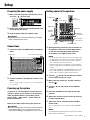 7
7
-
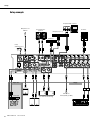 8
8
-
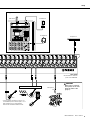 9
9
-
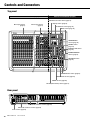 10
10
-
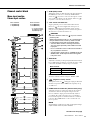 11
11
-
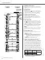 12
12
-
 13
13
-
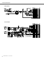 14
14
-
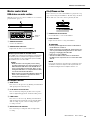 15
15
-
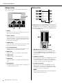 16
16
-
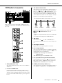 17
17
-
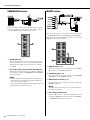 18
18
-
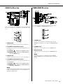 19
19
-
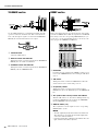 20
20
-
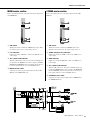 21
21
-
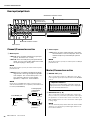 22
22
-
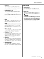 23
23
-
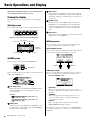 24
24
-
 25
25
-
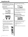 26
26
-
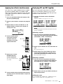 27
27
-
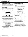 28
28
-
 29
29
-
 30
30
-
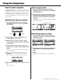 31
31
-
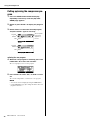 32
32
-
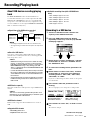 33
33
-
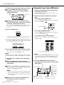 34
34
-
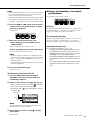 35
35
-
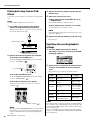 36
36
-
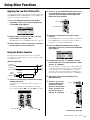 37
37
-
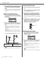 38
38
-
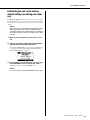 39
39
-
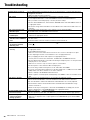 40
40
-
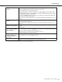 41
41
-
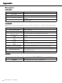 42
42
-
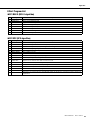 43
43
-
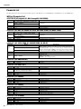 44
44
-
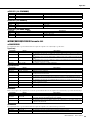 45
45
-
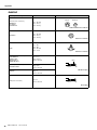 46
46
-
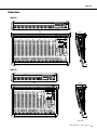 47
47
-
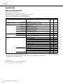 48
48
-
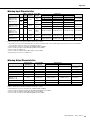 49
49
-
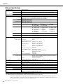 50
50
-
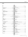 51
51
-
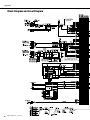 52
52
-
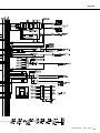 53
53
-
 54
54
-
 55
55
-
 56
56


Yamaha MGP24X Manual de usuario
- Categoría
- Equipo de música suplementario
- Tipo
- Manual de usuario
- Este manual también es adecuado para
en otros idiomas
- français: Yamaha MGP24X Manuel utilisateur
- italiano: Yamaha MGP24X Manuale utente
- English: Yamaha MGP24X User manual
- Deutsch: Yamaha MGP24X Benutzerhandbuch
- русский: Yamaha MGP24X Руководство пользователя
- Nederlands: Yamaha MGP24X Handleiding
- português: Yamaha MGP24X Manual do usuário
- dansk: Yamaha MGP24X Brugermanual
- polski: Yamaha MGP24X Instrukcja obsługi
- čeština: Yamaha MGP24X Uživatelský manuál
- svenska: Yamaha MGP24X Användarmanual
- Türkçe: Yamaha MGP24X Kullanım kılavuzu
- suomi: Yamaha MGP24X Ohjekirja
- română: Yamaha MGP24X Manual de utilizare
Artículos relacionados
-
Yamaha MGP12X Manual de usuario
-
Yamaha MG24 Manual de usuario
-
Yamaha MG06X El manual del propietario
-
-
-
-
-
Yamaha AG06 Manual de usuario
-
Yamaha CL5 El manual del propietario
-
Otros documentos
-
Peavey 1606M Manual de usuario
-
Alto TMX160DFX Guía de inicio rápido
-
-
Belkin TUNESTUDIO #F8Z109EA El manual del propietario
-
M-Audio Octane Guía del usuario
-
-
-
Alesis PRO TRACK El manual del propietario
-
Mark MPM 16352 USB Manual de usuario
-
Montarbo MC-R12FX Manual de usuario