Faber Stratus 36 SS Guía de instalación
- Categoría
- Campanas de cocina
- Tipo
- Guía de instalación
Este manual también es adecuado para

Installation Instructions
Use and Care Information
Instructions d'installation
Utilisez et d'entretien
Instrucciones de instalación
Información de uso y cuidado
STRATUS NB
STRTIS48SSNB
STRTIS36SSNB

2

3
Contents
Important Safety Instructions 4
Range hood Dimensions 7
Installation Height Requirements 7
Main Parts 8
Combinations Hoods And Motor Kits 10
Choose Your Ducting Method 11
Wiring Preparation 12
Ceiling Hood Install Preparation 13
Installation Information 14
Internal Blower Installation 15
External Blower Installation 17
Installation of Range Hood Body 20
Connect The Ducting 26
Wiring Box 2 Connection (Remote Blower Wiring Only) 27
House Wiring Box Connection 28
Use and Care Information 30
Wiring Diagram 33

4
READ AND SAVE THESE INSTRUCTIONS BEFORE YOU START INSTALLING
THIS RANGE HOOD
WARNING: - TO REDUCE THE RISK OF A RANGE TOP GREASE FIRE:
a) Never leave surface units unattended at high settings. Boilovers cause smoking and greasy spillovers that
may ignite. Heat oils slowly on low or medium setting.
b)AlwaysturnhoodONwhencookingathighheatorwhenambeingfood(i.e.CrepesSuzette,Cherries
Jubilee,PeppercornBeefFlambé).
c)Cleanventilatingfansfrequently.Greaseshouldnotbeallowedtoaccumulateonfanorlter.
d)Useproperpansize.Alwaysusecookwareappropriateforthesizeofthesurfaceelement.
WARNING: - TO REDUCE THE RISK OF INJURY TO PERSONS IN THE EVENT OF A RANGE TOP GREASE
FIRE,OBSERVETHEFOLLOWING*:
a)SMOTHERFLAMESwithaclose-ttinglid,cookiesheet,ormetaltray,thenturnofftheburner.BECAREFULTO
PREVENTBURNS.IftheamesdonotgooutimmediatelyEVACUATEANDCALLTHEFIREDEPARTMENT.
b) NEVER PICK UP A FLAMING PAN - You may be burned.
c)DONOTUSEWATER,includingwetdishclothsortowels-aviolentsteamexplosionwillresult.
d)UseanextinguisherONLYif:
1. YouknowyouhaveaClassABCextinguisher,andyoualreadyknowhowtooperateit.
2. Thereissmallandcontainedintheareawhereitstarted.
3. Theredepartmentisbeingcalled.
4. Youcanghttherewithyourbacktoanexit.
* Based on "Kitchen Firesafety Tips" published by NFPA
WARNING-TOREDUCETHERISKOFFIREORELECTRICSHOCK,donotusethisfanwithanysolid-
state speed control device.
WARNING-TOREDUCETHERISKOFFIRE,ELECTRICALSHOCK,ORINJURYTOPERSONS,OBSERVE
THE FOLLOWING:
1. Usethisunitonlyinthemannerintendedbythemanufacturer.Ifyouhaveanyquestions,contact
the manufacturer.
2. Beforeservicingorcleaningunit,switchpoweroffatservicepanelandlocktheservicedisconnecting
means to prevent power from being switched on accidentally. When the service disconnecting means
cannotbelocked,securelyfastenaprominentwarningdevice,suchasatag,totheservicepanel.
CAUTION:ForGeneralVentilatingUseOnly.DoNotUseToExhaustHazardousorExplosiveMaterials
and Vapors.
WARNING-TOREDUCETHERISKOFFIRE,ELECTRICALSHOCK,ORINJURYTOPERSONS,OBSERVE
THE FOLLOWING:
1. InstallationWorkAndElectricalWiringMustBeDoneByQualiedPerson(s)InAccordanceWithAll
ApplicableCodesAndStandards,IncludingFire-RatedConstruction.
2. Sufcientairisneededforpropercombustionandexhaustingofgasesthroughtheue(chimney)of
fuel burning equipment to prevent backdrafting. Follow the heating equipment manufacturer's guideline
andsafetystandardssuchasthosepublishedbytheNationalFireProtectionAssociation(NFPA),and
theAmericanSocietyforHeating,RefrigerationandAirConditioningEngineers(ASHRAE),andthe
local code authorities.
3. Whencuttingordrillingintowallorceiling,donotdamageelectricalwiringandotherhiddenutilities.
4. Ducted fans must always be vented to the outdoors.
IMPORTANT SAFETY INSTRUCTIONS

5
ALL WALL AND FLOOR OPENINGS WHERE THE RANGE HOOD IS INSTALLED MUST BE SEALED.
This Range Hood requires at least 35" of clearance between the bottom of the Range Hood and the cooking
surface or countertop. This hood has been approved by UL at this distance from the cooktop.
Consult the cooktop or range installation instructions given by the manufacturer before making any cutouts.
MOBILE HOME INSTALLATION The installation of this Range Hood must conform to the Manufactured
Home Construction and Safety Standards, Title 24 CFR, Part 3280 (formerly Federal Standard for Mobile Home
Construction and Safety, Title 24, HUD, Part 280).
Attention: This hood has been engineered to minimize electromagnetic interference (EMI) originating
from the consumer's home power source. However, in some home application, ambient EMI and
excessive EMI from other electronic sources can compromise the reliability of the remote control.
Please speak with your Faber Distributor about an optional spare part to further reduce EMI from
home sources.
• Venting system MUST terminate outside the home.
• DO NOT terminate the ductwork in an attic or other enclosed space.
• DO NOT use 4" laundry-type wall caps.
• Flexible-type ductwork is not recommended.
• DO NOT obstruct the ow of combustion and ventilation air.
• Failure to follow venting requirements may result in a re.
WARNING
!
VENTING REQUIREMENTS
Determine which venting method is best for your application. Ductwork can extend either through the wall or the roof.
The length of the ductwork and the number of elbows should be kept to a minimum to provide efcient performance. The
size of the ductwork should be uniform. Do not install two elbows together. Use duct tape to seal all joints in the ductwork
system. Use caulking to seal exterior walls and ceiling space opening around the cap.
Flexible ductwork is not recommended. Flexible ductwork creates back pressure and air turbulence
that greatly reduces performance.
Make sure there is proper clearance within the walls and ceiling space for exhaust duct before making cutouts. Do not
cut a joist or stud unless absolutely necessary. If a joist or stud must be cut, then a supporting frame must be constructed.
WARNING - To Reduce The Risk Of Fire, Use Only Metal Ductwork.
CAUTION-Toreduceriskofreandtoproperlyexhaustair,besuretoductairoutside–Donotventexhaustair
intospaceswithinwallsorceilingsorintoattics,crawlspaces,orgarages.
Cold Weather installations
An additional back draft damper should be installed to minimize backward cold air ow and a nonmetal-
lic thermal break should be installed to minimize conduction of outside temperatures as part of the vent
system. The damper should be on the cold air side of the thermal break. The break should be as close as
possible to where the vent system enters the heated portion of the house.

6
ELECTRICAL REQUIREMENTS
A 120 volt, 60 Hz AC-only electrical supply is required on a separate 15 amp fused circuit. A time-delay fuse or circuit breaker
is recommended. The fuse must be sized per local codes in accordance with the electrical rating of this unit as specied
on the serial/rating plate located inside the unit near the eld wiring compartment.
ELECTRICAL INSTALLATION WITH WIRING BOX
THIS UNIT MUST BE CONNECTED WITH COPPER WIRE ONLY. Wire sizes must conform to the requirements of the
National Electrical Code, ANSI/NFPA 70 - latest edition, and all local codes and ordinances. Wire size and connections
must conform with the rating of the appliance. Copies of the standard listed above may be obtained from:
National Fire Protection Association
Batterymarch Park
Quincy, Massachusetts 02269
This appliance should be connected directly to the fused disconnect (or circuit breaker) through exible, armored
or nonmetallic sheathed copper cable. Allow some slack in the cable so the appliance can be moved if servicing
is ever necessary. A UL Listed, 1/2" conduit connector must be provided at each end of the power supply cable
(at the appliance and at the junction box).
When making the electrical connection, cut a 1 1/4" hole. A hole cut through wood must be sanded until smooth.
A hole through metal must have a grommet.
• Electrical ground is required on this Range Hood.
• If cold water pipe is interrupted by plastic, nonmetallic gaskets or other materials, DO NOT use for
grounding.
• DO NOT ground to a gas pipe.
• DO NOT have a fuse in the neutral or grounding circuit. A fuse in the neutral or grounding circuit could
result in electrical shock.
• Check with a qualied electrician if you are in doubt as to whether the Range Hood is properly
grounded.
• Failure to follow electrical requirements may result in a re.
WARNING
!
StateofCaliforniaProposition65Warning(USonly)
WARNING
This product contains chemicals known to the State of California to cause cancer and birth defects or other
reproductive harm.
For more information go to www.P65Warnings.ca.gov

7
RANGE HOOD DIMENSIONS
INSTALLATION HEIGHT REQUIREMENTS
Recommended 60" mounting height above the cooking surface for best performance, but can be mounted up
to 72" maximum away the cooking surface.
An access point to the hood from the ceiling or soft must be made for installation and future access to the
range hood.
MAX. 72" OVER ELECTRIC / GAS
MIN. 35" OVER ELECTRIC / GAS

8
MAIN PARTS
REF. PART QTY
A
Hood Body, complete with: Controls, Lights, Filters. 1
B
Upper Mounting Bracket 2
C
Lower Mounting Bracket 2
D
Damper ø 6" 1
E
Remote Control 1
H
Drilling Template 1
REF
PART
QTY
F
Torx Bolts (1/4" x 9/16")
4
G
Pozi Screws (1/8" x 3/8")
8
D
E
A
B
C
F
G
H
8
AA-725973-1
1x
1x
C
1x
B
A
1x
3x 4x
1x
D E
1x
1x
1x
1x

9
CAUTION - To Reduce The Risk Of Fire And Electric Shock, Install This Range Hood Only With
Remote Blower Models RB900 kit or RB1200 kit Manufactured by Faber Or Integral Blowers
Manufactured by Faber, Model(s) IB600 kit, IB400 kit, IB300 kit or generic remote blower rated max
2.7A suitable for use with solid state speed control.
PARTS NEEDED
PART
6" Round Metal Ductwork
Wire connectors.
Drywall plugs or other suitable wall fasteners based on your installation.
ACCESSORIES AVAILABLE
ACCESSORY SKU#
Activated Charcoal Filter Accessory Kit #FILTER1
Washable Long-Lasting Activated Charcoal Filter Kit #FILTER1LL
Internal 600 PRO Blower IB600 #IB600 kit
Internal 400 Blower IB400 #IB400 kit
Internal 300 Blower IB300 #IB300 kit
Remote Blower 900 RB900 (10” Flange Included) #RB900 kit
Remote Blower 1200 RB1200 (10” Flange Included) #RB1200 kit
10" Flange for In-Line Blower #FLANGE10

10
COMBINATIONS HOODS AND MOTOR KITS
RB900 kit and RB1200 kit
(remote blower)
FLANGE10
(In-Line Blower)
IB600 kit, IB400 kit, IB300 kit
(internal blower)
3B
4B
Discard 6" Flange
Discard 10" Flange
withWireBox
Discard Wire Cable
Version 07/11 - Page 6
INSTALLATION
COMBINATIONS HOOD AND MOTOR KITS
CHOOSE A BLOWER FOR YOUR HOOD
After choosing the hood width and depth for your cooking
needs, next choose the type of blower appropriate for
your cooking.
NOTE: no other blower is
compatible with this hood, except for the
kits below.
# IB300 - Internal Blower Kit 300 cfm
# IB600 - Internal Blower Kit 600 cfm
# IB1200 - Internal Blower Kit 1200 cfm
# RB900 - Remote Blower Kit 900 cfm
# RB1200 - Remote Blower Kit 1200 cfm
# INLBKIT - In Line Blower Kit
(supply own in-line blower)
OPTIONAL ACCESSORIES AVAILABLE
• *Charcoal Filter
* it is highly recommended that professional style cooking always be
vented to the outside; for recirculating installations only, some ductwork is
required to exhaust the unit out of the cabinet. Replace as needed with the
same model
part # FILTER1
NOTE: The charcoal filter kit for use with the 300 / 600
cfm internal blower kit ONLY
CAUTION - To reduce risk of fire and electric shock, install this rangehood only with: Remote blower manufacturer by Faber
models RB900 and RB1200 or Integral blower manufactured by Faber models IB300 or IB600 or IB1200 or with INLBKIT and
generic in-line blower rated max 4.2 A suitable for use with solid state variable speed control
INLBKIT
1A
Keep
Keep 10" Flange
Blower
1B
Keep Blower
3A
2A
Keep 10" Flange
2A

11
Non Ducted - Recirculation Options
Ducted Venting Options
Activated Charcoal Filter Accessory FILTER1 or FILTER1LL required (Purchased separately).
Register cover for air duct exit is shown for design not included.
Attention: When used in recirculation mode, To Reduce the Risk of Fire and Shock use only conversion
kit Model FILTER1 or FILTER1LL.
6 "
A B
Register cover for air
duct exit is suggested.
CHOOSE YOUR DUCTING METHOD
Two men required for installation Wear work gloves for safety
Caution: If an elbow is required, do it as far away from the hood's exhaust opening as possible
6 "
Roof
Exterior
Wall

12
Open the lter cover panel. The lter cover panel
is held by a magnet catch, pull down with enough
force to release as shown below.
Remove the grease lters one at a time, pushing
them towards the back of the unit, and at the
same time pulling downward and set aside.
1 2
WIRING PREPARATION
WIRING BOX 1 for
connecting the Home
power supply cable
with the Hood.
WIRING BOX 2
for connecting the
External Blower with
the Hood.
HousePowerSupplyCableWiringBox1&RemoteBlowerWiringBox2
Choose wiring method based on blower type
1
2
3
1
2

13
3
Do not make any cutouts until you have decided whether this installation will be: ducted or non-ducted
and wiring has been prepared based on based on blower type.
CEILING HOOD INSTALL PREPARATION
Use a plumb line to mark the center of the
range on the ceiling.
Mark the centers.
4
5
DUE TO THE SIZE AND WEIGHT OF
THIS Range Hood, THE SUPPORT
MUST BE FIRMLY ATTACHED TO
THE CEILING. For plaster or sheet
rock ceiling, the support must be
attached to the joists. If this is not pos-
sible, a support structure must be built
behind the plaster or sheet rock. The
manufacturer assumes no responsibil-
ity for injury or damage caused by
improper installations.
WARNING
!
• For all installations, an access point to the hood must be created for installation and future maintenance
of the hood.
• Put a thick, protective covering over cooktop to protect from damage or dirt.
• Use the mounting template on the ceiling to determine placement of mounting screws on the ceiling.
• Mark the center of the holes in the ceiling template.
• Determine and make necessary cuts for the ductwork.
• Install ductwork before mounting the hood.
• Determine the proper location for the Power Supply Cable as indicated on the Template.
• Use a 1 1/4" Drill Bit to make this hole.
• Run the Power Supply Cable. Use caulking to seal around the hole.
• A knockout for threading through the Power Supply from the ceiling is located on the top of the Range
Hood.
• Do not connect the Power Cable to the Wiring Box or power up the hood at this time.
• Run enough power cable from the ceiling to reach the wiring box on the hood.
1 1/4"
H

14
CORRECT
NOT
CORRECT
In preparation for installation of the hood orient the hood with the control panel on the right as shown below
INSTALLATION INFORMATION
$[
PP
[
[

15
1
3
Unfasten the 4 screws to dismount the
Box for the blower.
The blower can be positioned in four different venting directions as shown.
Rotate the Box with Blower in the correct position.
2
Position Internal Blower as shown into the
removed Blower Box. Secure the Internal
Blower in the Blower Box with the two screws
provided with the Internal Blower.
INTERNAL BLOWER INSTALLATION
Left
Right
Back
Front
Separate Box and Range Hood
Choose the Box position (Left-Right-Back-Front)
Attach the Internal Blower
Phillips ScrewdriverTorx Screwdriver
lfyouusetheinternalblowerkit,IB600kitorIB400kitorIB300kit,pleasethrowawaythetheange
(3B)andthecable(4B),givenwiththeinternalblowerkit,shownonpage10anduseonly10”Flange.

16
4
Attach the Box with the Blower with the same 4 screws removed previously.
After the blower is mounted
in the hood, plug the harness
with molex originating from the
control box, into the blower.
IMPORTANT: Do not use the
harness that came with your
internal blower kit (IB600 kit,
IB400 kit, IB300 kit).
IMPORTANT: Do not connect
the Control Cable to Wiring
Box 1 or Wiring Box 2 for
internal blower installation.
IMPORTANT: Do NOT use
wiring box 2 for an internal
blower installation.
5
Connect the cable to the Motor.
Connect the Electric Cable
Attach Motor Box to the Range Hood
Torx Screwdriver
1
2

17
1
2
Unfasten the 4 screws to dismount the Blower Box from the hood body and to save screws.
The Blower Box is not used for Remote Blower installation and can be discarded or saved for future
use if converted to Internal Blower.
Attach 10" FLANGE (2A) with 4 screws provided in
the hardware bag as shown.
lfyouusetheremoteblowerkit,RB900kitorRB1200kitorIn-LineBlowerOption,please
throwawaytheange(3A)givenwiththeremoteblowerkit,shownonpage10.
EXTERNAL BLOWER INSTALLATION
Separate the Box from the Range Hood
Attach optional FLANGE 10" (2A)
Torx Screwdriver
Torx Screwdriver

18
3
Connect the Hood body air outlet with the
Remote Blower air outlet.
4
Connect to Air Outlet
Connection to Box 2 (Remote Blower Wiring Box)
1. From inside the hood connect the cable
to the wiring box 2 as shown in the image
to the right.
2. From inside the hood, remove the cover from the
wiring box 2 by removing two screws.
3. Break the correct hole in the Wiring Box 2 for
passing the cables from the remote blower.
2
2
Box
1
2

19
Fixing the Security Cable
Fix the Free part of Security Cable at the panel with a Screw 7 supplied.
A
B
C

20
INSTALLATION OF RANGE HOOD BODY
X = A - 5 1/16"
$
PP
; $PP
;
%[
5 1/16"
6
As shown, you have to
accommodate for the
height of the hood body
into your space overhead.
After determining bracket
height use the 8 Screws
from Component Page 8 to
assemble brackets.
$
PP
; $PP
;
%[
5
Min. 7 5/16"
Max. 12 13/16"
Option A
Steps 7a-7b-7c is an option for mounting and hood when access is available from above the ceiling/soft
(See page 20).
Option B
Steps 8a-8b-8c is an option for mounting the hood to the brackets when no access is available from above
and the soft is already completed (See page 22).
Choose the correct method of bracket installation
Assemble the Range Hood Mounting Brackets
Ref. Size Picture
G
1/8" x 3/8"
G

21
See below for a detailed image on
drilling the holes onto the fastening
surface (inside ceiling or soft) that
will then be used to mount the bracket
xtures.
The fasteners used must be
compatible with the 5/16" hole and are
purchased separately.
Ceiling Mark
7.a
OPTION A - HOOD INSTALLATION BEFORE THE SOFFIT IS COMPLETED
Use this installation if you have access from above to install the range hood
Bracket Installation on Ceiling
Use external holes created with drilling template for location of the ceiling fasteners (purchased separately).
Use wall plugs or other securing hardware in conjunction with the ceiling fasteners (purchased separately).
(1) Use a 5/16" Drill Bit to make these external hole.
(2) Use wall plugs if appropriate or other securing hardware in conjunction with the ceiling fasteners (purchased
separately).
(3) Use appropriate screws or other securing hardware in conjunction with the ceiling fasteners (purchased
separately) to attach the brackets.
7.b
´
[
³
´
1 2 3

22
´
[
[
7.c
Ref. Size Picture
F
1/4" x 9/16"
Attach the Range Hood on the Bracket
Access is needed in the space above. Leave an access point in the soft for future access to the range hood.
Attach the Hood body to the hood ceiling brackets by use the 4 Screws
F
from the component list on Page
6 to attach the hood body to the hood ceiling brackets.
IMPORTANT: Check to make
sure the controls are facing
you and to the right.

23
Cutout for Ceiling / Sot
8.a
See image with dimensions
for ceiling cutout.
Ø 5/16”
x4
x4
475
878
15
3/4
”
23
5/8
” - 31
5/8
”
18
11/16
” - 26
9/16
”
23
5/8” - 31
5/8
”
X
Y
Important:
• Steps 8a-8b-8c-8d is the option for mounting the hood to the brackets when access is NOT available from
above the ceiling/soft.
• The brackets are rst mounted into the ceiling soft and the hood is mounted to the brackets from in side
the hood.
OPTION B - HOOD INSTALLATION AFTER THE SOFFIT IS COMPLETED
$
PP
; $PP
;
%[
$
PP
; $PP
;
%[
Use this installation if don't have access from above to install the range hood
Hood X Y
36" 18 11/16" 34 9/16"
48" 26 9/16" 46 3/8"

24
8.b
See below for a detailed image on drilling the holes onto the fastening surface (inside ceiling or soft) that
will then be used to mount the bracket xtures. The fasteners used must be compatible with the 5/16" hole
and are purchased separately.
Ceiling Bracket Installation for Sot
Bracket Installation on Ceiling
Use more internal holes created with drilling template for location of the ceiling fasteners(purchased
separately).
Use wall plugs or other securing hardware in conjunction with the ceiling fasteners (purchased separately).
(1) Use a 5/16" Drill Bit to make these internal hole.
(2) Use wall plugs if appropriate or other securing hardware in conjunction with the ceiling fasteners (purchased
separately).
(3) Use appropriate screws or other securing hardware in conjunction with the ceiling fasteners (purchased
separately) for attach the Brackets.
8.c
[
´
³
´
1
2
3

25
Use the 4 Screws from the Component list to attach the
hood ceiling brackets from the bottom inside the hood.
8.d
1 2
C (M6x15)
3
Ref. Size Picture
F
1/4" x 9/16"
Use the Screws to attach the hood to the ceiling brackets
Attach the Range Hood on the Bracket
Ø 8 mm
A (5x70)
x4
x4
475
878
400
600 -
803
475 - 675
878 - 1178
Ø 5/16”
x4
x4
1
2
Attach the Range Hood on the brackets.

26
Install the Damper
Connect to Air Outlet
Install Damper that is included with the Hood before connecting to the ductwork. Seal with foil
duct tape.
Connect the hood to the pipe for air outlet. Use foil duct tape to seal the joint.
CONNECT THE DUCTING
9
10
Ducted Venting Installation
H
I
A (5x70)
Ø 8 mm
x4
x4

27
12
Install Activated Charcoal Filter Kit
• Attach each charcoal lter to the black grid on each side of
the blower.
• Press the charcoal lter tightly to the black grid on the blower
side and rotate the lter clockwise (towards the front of the
insert hood) until it locks into place (A).
• Turn counterclockwise (towards the back of the insert hood)
to remove (B).
Required Activated Charcoal Filter
Accessory - sku # - FILTER1 or
FILTER1LL (purchased separately)
´
Keep the return air duct at least 40" away from the side of the Range Hood.
0LQFP
40"
11a
11b
Information for Recirculation Hole
Recirculation Hole
Non Ducted - Recirculation Options
A
B

28
IMPORTANT: ONLY FOR EXTERNAL BLOWER INSTALLATION
13
WIRING BOX 2 CONNECTION
(Remote Blower Wiring Box)
• Connect the cable from the Remote Blower with the two wires inside the Wiring Box 2 by twist-on type
wire connector and matching the color:
- Black with Black
- White with White
• Connect the green ground wire from remote blower to green ground screw.
• Replace the eld wiring compartment cover.
• Check the Wiring Diagram.
A. Remote Blower power supply cable.
B. Black wires.
C. UL listed wire connectors.
D. White wires.
E. Internal Hood Cable.
F. Green ground screw.
1
2
A
E
D
C
B
F

29
Installation Of House Power
WiringBoxConnection1
1. Remove the cover from the
eld wiring compartment. DO
NOT turn on the power until
installation is complete!
2. Connect the Power Supply
Cable to the Range Hood.
3. Connect the Green (Green
and Yellow) ground wire
under the Green grounding
screw.
4. Attach the White lead of the
power supply to the White
lead of the Range Hood
with a twist-on type wire
connector.
5. Attach the Black lead of the
power supply to the Black
lead of the Range Hood
with a twist-on type wire
connector.
6. Replace the Wiring Box 1
cover and the grease lters.
7. Check the Wiring Diagram.
A. Home power supply cable.
B. Black wires.
C. UL listed wire connectors.
D. White wires.
E.Green(orbare)groundwirefromhomepowersupplytobeconnectedtogreengroundscrew.
F. Range hood power supply cable.
14
E
A
F
D
C
B
1615
Close the lter cover panel.Replace the grease lters.
1
2
HOUSE WIRING BOX CONNECTION
Wiring House Power to the Hood

30
USE AND CARE INFORMATION
For Best Results
Start the Range Hood several minutes before cooking to develop proper airow. Allow the Range Hood to operate for
several minutes after cooking is complete to clear all smoke and odors from the kitchen.
Button Function Led
Turns the lights on/off at maximum strength. -
Press and hold the button for approximately 2 seconds to turn the Dimmer
Lights On/Off.
-
Turns the motor on/off at speed one. ON
Delay function:
Press and hold the button for approx. 3 seconds to Activate/Deactivate the
Delay function (automatic switching off of the Motor, and the Lighting with a 30
min. delay). Cannot be enabled when Intensive is on.
Turns the Motor on at speed two. ON
Activate Charcoal Filter Alarm
Press and hold the button for approximately 5 seconds, with all the hood turned
off (Motor and Lights), to turn the alarm on. The relevant LED ashes twice
to conrm. To turn the alarm off, press the button again and hold for at least 5
seconds. The relevant LED ashes once.
Turns the Motor on at speed three. ON
Grease Filter Alarm
To reset the alarm: press and hold the button for approximately 3 seconds, with
the hood turned off (Motor and Lights), and until the LED S1 ashes three times.
Turns the Motor on at INTENSIVE Speed.
This speed is timed to run for 6 minutes. At the end of this time, the system
returns automatically to the speed that was set before. If it is activated with the
motor turned off, the hood will switch to OFF at the end of the time.
ON
S1
Signals the Metal Grease Filter saturation alarm, indicating that it is necessary
to wash the lters. The alarm is triggered after the Hood has been in operation
for 100 working hours.
ON
When this is activated, it signals:
The Activated Charcoal Filter saturation alarm, indicating that the lter must be
changed;
The Metal Grease Filters must also be washed. The Activated Charcoal Filter
saturation alarm turns on after the Hood has been working for 200 hours.
Flashing.

31
Remote control information
Installing the Battery
• The remote control is powered by a CR2032 type 3 V battery (not included).
• Remove the screw and install the battery.
• Check that the battery is installed with the " + " side up.
Caution:
• Do not place the remote control near heat sources.
• Do not discard the batteries with normal waste, they must
be put into the specic containers.
• Make sure the battery compartment is screwed down at
and is fully tightened..
Remote Control control panel
Motor On/Off.
-
-
Lights On / Off.
Press for 2 seconds to Activate Dimmer.
Activates/Deactivates Intensive operation
Brief pressure: Activates/Deactivates the Delay function: automatic switch-off with a 30’ delay. The
display shows the operating speed and the dot at the bottom right ashes once a second.
Increases the working speed each time it is pressed
Decreases the working speed each time it is pressed

32
Cleaningmetalgreaselters
These can be washed in the dishwasher, and need to
be cleaned whenever the S1 LED comes on or at least
once every 2 months of use, or more frequently if use
is particularly intensive.
Resetting the Grease Filter Alarm
• Turn the Lights and the Hood off.
• Press
and hold for at least 3 seconds, until
LED ashes three times in conrmation.
Cleaning the Filters
• Open the Panel.
• Remove the Filters one at a time, pushing them
towards the back of the unit and at the same time
pulling downward.
• Wash the Filters without bending them, and leave them
to dry completely before replacing. (If the surface of
the lter changes color as time goes by, this will have
absolutely no effect on the efciency of the lter itself.)
• Replace the grease lters, taking care to ensure that
the handle faces forward.
• Completely dry the filters before reinstalling.
Otherwise, left over grease may heat and drip.
• Close the Panel.
Replacing Activated Charcoal Filter
They cannot be washed or regenerated, and must be
changed when LED S1 starts to ash, or at least once
every 4 months. The Alarm signal, if it has been activated,
only appears when the Hood Blower is turned on.
Resetting the alarm signal
• Turn the Lights and the Hood Blower off.
• Press
and hold for at least 3 seconds, until
LED ashes three times in conrmation.
Cleaning the Filters
• Open the Panel.
• Remove the Metal Grease Filter.
• Remove the saturated Activated Charcoal Filters, as
indicated (A).
• Fit the new Filters, as indicated (B).
• Replace the Metal grease lters.
• Close the Panel.
A
B
1
2
3

33
CleaningExteriorsurfaces
CleaningExteriorsurfaces:
Please note, abrasives and scouring agents can scratch
range hood nishes and should not be used to clean
nished surfaces.
StainlessSteelnishcleaninginstructions:
Clean exterior surfaces with a commercially available
stainless steel cleaner.
PaintedGraynishcleaninginstructions:
Clean exterior surfaces with hot soapy water.
Lighting
• LED lights must be replaced by Faber factory
authorized service.

34
January 4, 2016
FABER CONSUMER WARRANTY & SERVICE
All Faber products are warranted against any defect in materials or workmanship for the original purchaser
for a period of 1 year from the date of original purchase (requires proof of purchase). This warranty covers
labor and replacement parts. Faber, at its option, may repair or replace the product or components
necessary to restore the product to good working condition. To obtain warranty service, contact the dealer
from whom you purchased the range hood, or the local Faber distributor. If you cannot identify a local Faber
distributor, contact us at (508) 358-5353 for the name of a distributor in your area.
The following is not covered by Faber's warranty:
1. Service calls to correct the installation of your range hood, to instruct you how to use your range hood, to
replace or repair house fuses or to correct house wiring or plumbing.
2. Service calls to repair or replace range hood light bulbs, fuses or filters. Those consumable parts are
excluded from warranty coverage.
3. Repairs when your range hood is used for other than normal, single-family household use.
4. Damage resulting from accident, alteration, misuse, abuse, fire, flood, acts of God, improper installation,
installation not in accordance with electrical or plumbing codes or Faber documentation, or use of products
not approved by Faber.
5. Replacement parts or repair labor costs for units operated outside the United States or Canada, including
any non-UL or C-UL approved Faber range hoods.
6. Repairs to the hood resulting from unauthorized modifications made to the range hood.
7. Expenses for travel and transportation for product service in remote locations and pickup and delivery
charges. Faber range hoods should be serviced in the home.
THIS WARRANTY DOES NOT ALLOW RECOVERY OF INCIDENTAL OR CONSEQUENTIAL DAMAGES, INCLUDING, WITHOUT
LIMITATION, DIRECT, INDIRECT, INCIDENTAL, SPECIAL OR CONSEQUENTIAL DAMAGES, PERSONAL INJURY/WRONGFUL
DEATH OR LOST PROFITS FABER WARRANTY IS LIMITED TO THE ABOVE CONDITIONS AND TO THE WARRANTY PERIOD
SPECIFIED HEREIN AND IS EXCLUSIVE. EXCEPT AS EXPRESSLY SPECIFIED IN THIS AGREEMENT, FABER DISCLAIMS ALL
EXPRESS OR IMPLIED CONDITIONS, REPRESENTATIONS, AND WARRANTIES INCLUDING, WITHOUT LIMITATION, ANY
IMPLIED WARRANTIES OF MERCHANTABILITY OR FITNESS FOR A PARTICULAR PURPOSE
.
This warranty gives you specific legal rights that may vary from state to state.
Model#: ______________________________ Serial #: _____________________________

35
Table des matières
Importantes consignes de sécurité 37
Dimensions hotte 40
Hauteur requise pour l’installation 40
Pièces principales 41
Ensembles hottes et trousses de moteurs 43
Choisir la méthode de canalisation 44
Préparation du branchement 45
Préparation de l’installation de la hotte de plafond 46
Information relative à l’installation 47
Installation du ventilateur interne 48
Installation du ventilateur externe 50
Installation du bâti de la hotte 53
Raccorder les canalisations 59
Branchement du boîtier de connexion 2 (Connexion à distance uniquement) 61
Branchement du boîtier de connexion au réseau domestique 62
Information relative à l’utilisation et l’entretien 63
Schéma de câblage 67

36
VEUILLEZ LIRE ET CONSERVER LA PRÉSENTE NOTICE AVANT DE COMMENCER
L'INSTALLATION DE LA HOTTE DE CUISINE
AVERTISSEMENT : - POUR RÉDUIRE LE RISQUE D'UN FEU DE GRAISSE SUR LA TABLE DE CUISSON :
a)Nelaissezjamaissanssurveillancelesélémentsdelasurfacedecuissonàtempératureélevée.Lesbouillonnements
excessifspeuventprovoquerdelafuméeetlesdébordementsdegraissepeuvents'enammer.L'huiledoitêtre
chaufféelentement,àunetempératurebasseoumoyenne.
b)Assurez-vousdetoujoursmettreenmarchelahottelorsquevouscuisinezàtempératureélevéeoupréparezun
metsambé(p.ex.crêpesSuzette,cerisesjubilé,bœufambé).
c)Nettoyezrégulièrementlesventilateursd'aspiration.Assurez-vousdenepaslaisserdelagraisses'accumuler
surleventilateurouleltre.
d)Utiliseztoujoursdespoêlesetcasserolesdelatailleappropriée.Utiliseztoujoursdesustensilesdecuisinedela
tailleadaptéeàcelledel'élémentchauffant.
AVERTISSEMENT:-POURPRÉVENIRLESBLESSURESENCASDEFEUDEGRAISSESURLATABLEDECUISSON,
SUIVEZLESRECOMMANDATIONSSUIVANTES*:
a)ÉTOUFFEZLESFLAMMESàl'aided'uncouverclehermétique,d'uneplaqueàbiscuitsoud'unplateaumétallique,
puiséteignezlebrûleur.FAITESATTENTIONAUXBRÛLURES.Silefeunes'éteintpasimmédiatement,QUITTEZ
LES LIEUX ET APPELEZ LES POMPIERS.
b)NEPRENEZJAMAISUNECASSEROLEENFLAMME-Vouspourriezvousbrûler.
c)N'UTILISEZJAMAISDEL'EAU,niunlingeàvaisselleouuntorchonmouillé,pouréteindrelefeu.Celapourrait
provoqueruneviolenteexplosiondevapeur.
d)UtilisezunextincteurUNIQUEMENTsi:
1. Vousêtescertainqu'ils'agitd'unextincteurdeclasseABCetquevousconnaissezbiensonmoded'emploi.
2. Lefeuestdefaibleintensitéetselimiteàl'endroitoùiladémarré.
3. Lespompiersontdéjàétéappelés.
4. Unevoiedesortiesetrouvederrièrevouspendantquevouséteignezlesammes.
* D'après le guide « Kitchen Firesafety Tips » publié par la NFPA aux États-Unis
AVERTISSEMENT -POUR RÉDUIRELERISQUE D'INCENDIEOU DE CHOCÉLECTRIQUE, n'utilisezjamaisce
ventilateurenassociationavecundispositifderéglagedevitesseàsemi-conducteurs.
AVERTISSEMENT - POUR RÉDUIRE LES RISQUES D'INCENDIE, DE CHOC ÉLECTRIQUE OU DE BLESSURE
CORPORELLE,RESPECTEZLESINSTRUCTIONSSUIVANTES:
1. Utilisezcetappareiluniquementdelafaçonprévueparlefabricant.Pourtoutequestion,communiquezavec
le fabricant.
2. Avantdeprocéderàl'entretienouaunettoyagedel'appareil,coupezl'alimentationauniveaudupanneau
électriqueetverrouillez-lepourvousassurerquel'électricitén'estpasrétablieaccidentellement.S'iln'estpas
possibledeverrouillerledispositifd'interruptiondel'alimentation,afchezdefaçonfermeetbienvisibleun
avisdedanger,parexempleàl'aided'uneétiquettesurlepanneau.
ATTENTION:Destinéàunusagedeventilationgénéraleuniquement.N'utilisezpascedispositifpourl'aspiration
devapeursoudematériauxdangereuxouexplosifs.
AVERTISSEMENT - POUR RÉDUIRE LES RISQUES D'INCENDIE, DE CHOC ÉLECTRIQUE OU DE BLESSURE
CORPORELLE,RESPECTEZLESINSTRUCTIONSSUIVANTES:
1. L'installationetlebranchementélectriquedoiventêtreréalisésparuntechnicienqualiéetconformémentà
touslescodesetnormesenvigueur,incluantceuxconcernantlaconstructionàl'épreuvedufeu.
2. Andegarantirunecombustionetuneévacuationadéquatesdesgazparlesconduitesdelacheminéedes
appareilsàcombustion,unebonneaérationestnécessairepouréviterlerefoulement.Respectezleslignes
directricesfourniesparlefabricantdumatérielchauffant,ainsiquelesnormesdesécuritécommecelles
publiéesparlaNationalFireProtectionAssociation(NFPA)etlaAmericanSocietyforHeating,Refrigeration
andAirConditioningEngineers(ASHRAE)auxÉtats-Unis,ainsiquelescodesenvigueurdansvotrerégion.
IMPORTANTES CONSIGNES DE SÉCURITÉ

37
3. Lorsquevousfaitesuneouvertureoupercezdansunmurouleplafond,veillezànepasendommagerlesls
électriquesoud'autresdispositifscachés.
4. Lesventilateurscanalisésdoiventtoujoursêtreraccordésàl'extérieur.
TOUTE OUVERTURE DANS LE MUR OU LE PLANCHER À PROXIMITÉ DE LA HOTTE DOIT ÊTRE SCELLÉE.
Un espace libre d'au moins 35" est requis entre le bas de la hotte et la surface de cuisson ou le comptoir. Cette hotte a été
homologuée par l'UL à cette distance de la surface de cuisson.
Consultez la notice d'installation de la surface de cuisson ou de la cuisinière fournie par le fabricant avant de pratiquer des
ouvertures. INSTALLATION DANS UNE MAISON MOBILE L'installation de cette hotte doit être conforme à la Partie 3280
de la norme Manufactured Home Construction and Safety Standards, Title 24 CFR (précédemment la partie 280 de la norme
Federal Standard for Mobile Home Construction and Safety, Title 24, HUD).
À noter : La présente hotte a été conçue pour réduire au minimum l’interférence électromagnétique
(EMI) provenant de l’alimentation électrique domestique. Il peut toutefois survenir que, dans certaines
applications domestiques, l’EMI ambiante et l’EMI excessive des autres dispositifs électroniques
puissent nuire au fonctionnement de la télécommande.
Renseignez-vous auprès de votre distributeur Faber au sujet d’une pièce de rechange en option
permettant de réduire l’EMI des sources domestiques.
CRITÈRES DE VENTILATION
Déterminez quelle méthode de ventilation est mieux adaptée à votre application. Les conduits peuvent passer par le mur ou le toit.
Pour garantir une meilleure efcacité, la longueur des conduits et le nombre de coudes doivent être le plus limités que possible.
Le diamètre des conduits devrait être uniforme. N'installez pas deux coudes ensemble. Utilisez un ruban pour canalisations
an de sceller tous les joints du système de conduits. Utilisez un calfeutrage pour sceller les ouvertures dans le mur extérieur
ou le plafond, autour du clapet.
Il n'est pas recommandé d'utiliser des conduits exibles. Les conduits exibles provoquent une contre-
pression et de la turbulence qui diminuent grandement l'ecacité de l'appareil.
Assurez-vous que l'espace libre dans le mur ou le plafond est sufsant pour le conduit d'évacuation avant de pratiquer les
ouvertures. Ne coupez jamais une poutre ou un chevron, sauf si c'est absolument nécessaire. S'il s'avère nécessaire de
couper une poutre ou un chevron, la construction d'un renforcement est requise.
AVERTISSEMENT - Pour réduire le risque d'incendie, utilisez uniquement des conduits métalliques.
ATTENTION-Pourréduirelerisqued'incendieetpourévacueradéquatementl'air,assurez-vousderaccorderles
conduitsàl'extérieur–Nediffusezpasl'aird'évacuationdansdesespacesàl'intérieurdesmursouduplafond,ou
encoreàl'intérieurd'ungrenier,d'unegalerietechniqueoud'ungarage.
•
Le système de ventilation DOIT déboucher à l'extérieur.
• NE FAITES PAS déboucher les conduits dans un grenier ou un autre endroit fermé.
• N’UTILISEZ PAS un clapet de sécheuse mural de 4".
• Il n'est pas recommandé d'utiliser des conduits exibles.
• N’ENTRAVEZ PAS le ux de l'air de combustion et de ventilation.
• Le non-respect des exigences en matière de ventilation pourrait entraîner un incendie.
AVERTISSEMENT
!
Installation dans les climats froids
Le système de ventilation doit prévoir un registre antirefoulement supplémentaire pour réduire le ux d'air froid inverse,
ainsi qu'une barrière thermique non métallique pour réduire la conduction des températures extérieures. Le registre
doit être installé du côté air froid par rapport à la barrière thermique. La barrière thermique doit être positionnée le
plus près que possible de l'endroit où le système de ventilation pénètre dans la partie chauée de la maison.

38
FICHE TECHNIQUE ÉLECTRIQUE
Une alimentation de courant alternatif de 120 volts à 60 Hz est requise sur un circuit à fusible distinct de 15 ampères.
Il est recommandé d'installer un fusible temporisé ou un disjoncteur. Le fusible doit être calibré conformément aux
codes en vigueur pour les caractéristiques nominales électriques de l'appareil, indiquées sur la plaque signalétique
située à l'intérieur de l'appareil, à proximité du compartiment des câblages externes.
INSTALLATION ÉLECTRIQUE AVEC BOÎTIER DE CONNEXION
CET APPAREIL DOIT ÊTRE UNIQUEMENT BRANCHÉ À L'AIDE DE FILS DE CUIVRE. Le calibre des ls
doit être conforme aux critères de la dernière édition du National Electrical Code, de l'ANSI/NFPA 70 et de
l'ensemble des codes et réglementations en vigueur. Le calibre des ls et les connexions doivent être adaptés
aux caractéristiques nominales de l'appareil. Il est possible de se procurer un exemplaire des normes indiquées
ci-dessus en communiquant avec :
National Fire Protection Association
Batterymarch Park
Quincy, Massachusetts 02269 (États-Unis)
Cet appareil devrait être branché directement au sectionneur à fusible (ou au disjoncteur) par un câble exible de
cuivre avec blindage ou gaine non métallique. Laissez un peu de jeu dans le câble pour permettre le déplacement
de l'appareil si des travaux d'entretien s'avéraient nécessaires. Un raccord de conduit homologué par l'UL de 1/2"
doit être installé aux deux extrémités du câble d'alimentation (au niveau de l'appareil et de la boîte de liaison).
Lors de la réalisation du branchement électrique, réalisez un trou de 1 1/4". S'il s'agit d'un trou dans le bois, il
doit être poncé pour le rendre lisse. S'il s'agit d'un trou dans le métal, un passe-ls est requis.
• Une mise à la terre électrique est requise pour cette hotte.
• N'UTILISEZ PAS un tuyau d'eau froide pour la mise à la terre si celui-ci est branché par des joints en
plastique, par des rondelles non métalliques ou d'autres matériaux.
• N'UTILISEZ PAS une conduite de gaz pour la mise à la terre.
• N'INSTALLEZ PAS un fusible sur le circuit neutre ou le circuit de mise à la terre. La présence d'un
fusible dans le circuit neutre ou de mise à la terre peut entraîner un choc électrique.
• Consultez un électricien qualié si vous n'êtes pas certain de la mise à la terre de la hotte.
• Le non-respect des exigences de la che technique électrique pourrait entraîner un incendie
.
AVERTISSEMENT
!
Avertissementrelatifàlaproposition65del’ÉtatdeCalifornie(États-Unisuniquement)
AVERTISSEMENT
Ce produit contient des éléments chimiques que l’État de Californie considère comme étant cancérigènes ou
causant des malformations congénitales ou d’autres troubles de la reproduction.
Pour de plus amples renseignements, consultez le site www.P65Warnings.ca.gov

39
DIMENSIONS DE LA HOTTE
HAUTEUR REQUISE POUR L’INSTALLATION
Il est recommandé de monter la hotte à une hauteur de 60" de la surface de cuisson pour un résultat optimal,
mais il est possible de la monter jusqu’à un maximum de 72" au-dessus de la surface de cuisson.
MIN. 35" D’ÉCART (ÉLECTRIQUE/AU GAZ) MAX. 72" D’ÉCART (ÉLECTRIQUE/AU GAZ)
Un point d’accès à la hotte doit être créé dans le plafond ou le parement pour l’installation et en vue d’accéder
plus tard à la hotte.

40
PIÈCES PRINCIPALES
RÉF. PIÈCE QTÉ
A
Bâti de la hotte avec : Commandes, éclairages, ltres. 1
B
Bride de montage supérieure 2
C
Bride de montage inférieure 2
D
Registre ø 6" 1
E
Télécommande 1
H
Gabarit de perçage 1
RÉF. PIÈCE QTÉ
F
Vis à tête étoile (1/4" x 9/16")
4
G
Vis à tête Pozidriv (1/8" x 3/8")
8
D
E
A
B
C
F
G
H
8
AA-725973-1
1x
1x
C
1x
B
A
1x
3x 4x
1x
D E
1x
1x
1x
1x

41
ATTENTION - Pour réduire le risque d'incendie ou de choc électrique, installez cette hotte
uniquement avec les ventilateurs à distance RB900 kit ou RB1200 kit, fabriqués par Faber, avec
les ventilateurs intégraux fabriqués par Faber, modèles IB600 kit, IB400 kit ou IB 300 kit, ou
encore avec un ventilateur à distance générique ayant une valeur nominale maximale de 2,7 A et
compatible avec une commande de vitesse à semi-conducteur.
PIÈCES REQUISES
PIÈCE
Conduit métallique 6" circulaire
Connecteurs de ls.
Chevilles pour cloison sèche ou autre système de xation mural, en
fonction de votre installation.
ACCESSOIRES DISPONIBLES
ACCESSOIRE NO D’ARTICLE#
Trousse de ltre à charbon actif accessoire #FILTER1
Trousse de ltre à charbon actif longue durée lavable #FILTER1LL
Ventilateur interne 600 PRO IB600 #IB600 kit
Ventilateur interne 400 IB400 #IB400 kit
Ventilateur interne 300 IB300 #IB300 kit
Ventilateur à distance 900 RB900 (asque 10” inclus) #RB900 kit
Ventilateur à distance 1200 RB1200 (asque 10” inclus) #RB1200 kit
Flasque 10" pour ventilateur en ligne #FLANGE10

42
ENSEMBLES HOTTE ET TROUSSE MOTEUR
RB900 kit et RB1200 kit
(ventilateur à distance)
FLANGE10
(Ventilateur en
ligne)
IB600 kit, IB400 kit,
IB300 kit
(ventilateur interne)
3B
4B
Jeterasque6"
Jeterasque10"
avecboîtierdeconnexion
Jeter câble de branchement
Version 07/11 - Page 6
INSTALLATION
COMBINATIONS HOOD AND MOTOR KITS
CHOOSE A BLOWER FOR YOUR HOOD
After choosing the hood width and depth for your cooking
needs, next choose the type of blower appropriate for
your cooking.
NOTE: no other blower is
compatible with this hood, except for the
kits below.
# IB300 - Internal Blower Kit 300 cfm
# IB600 - Internal Blower Kit 600 cfm
# IB1200 - Internal Blower Kit 1200 cfm
# RB900 - Remote Blower Kit 900 cfm
# RB1200 - Remote Blower Kit 1200 cfm
# INLBKIT - In Line Blower Kit
(supply own in-line blower)
OPTIONAL ACCESSORIES AVAILABLE
• *Charcoal Filter
* it is highly recommended that professional style cooking always be
vented to the outside; for recirculating installations only, some ductwork is
required to exhaust the unit out of the cabinet. Replace as needed with the
same model
part # FILTER1
NOTE: The charcoal filter kit for use with the 300 / 600
cfm internal blower kit ONLY
CAUTION - To reduce risk of fire and electric shock, install this rangehood only with: Remote blower manufacturer by Faber
models RB900 and RB1200 or Integral blower manufactured by Faber models IB300 or IB600 or IB1200 or with INLBKIT and
generic in-line blower rated max 4.2 A suitable for use with solid state variable speed control
INLBKIT
1A
Conserver
Conserverasque10"
Ventilateur
1B
Conserver Ventilateur
3A
2A
Conserver
asque10"
2A

43
Options de recyclage sans canalisation
Options avec ventilation canalisée
Filtre à charbon actif accessoire FILTER1 ou FILTER1LL requis (acheté séparément).
Le couvercle du registre de la sortie d’air est illustré à titre indicatif; il n’est pas inclus.
À noter: Pour réduire le risque d’incendie ou de choc électrique lorsque l’appareil est en mode
recyclage, utilisez uniquement le modèle FILTER 1 ou FILTER1LL pour trousse de conversion.
6"
A B
Recommandé
d’utiliser un
couvercle de registre
à la sortie d’air.
CHOISIR LA MÉTHODE DE CANALISATION
Deux personnes requises
pour l’installation
Portez des gants
par mesure de sécurité.
Attention : Si vous devez installer un coude, placez-le le plus loin possible de l’ouverture d’évacuation
de la hotte.
6"
Toit
Mur
extérieur

44
Ouvrez le panneau de protection du ltre. Le
panneau de protection du ltre est retenu par
un dispositif magnétique. Tirez vers le bas avec
force pour le dégager, comme illustré ci-dessous.
Retirez les ltres à graisse un à un, en les
poussant vers l'arrière de l'appareil et en les tirant
vers le bas simultanément. Mettez-les à part.
1 2
PRÉPARATION DU BRANCHEMENT
Boîtier de
connexion 1 pour le
branchement du câble
d’alimentation du
réseau domestique à
la hotte.
BOÎTIER DE
CONNEXION 2
pour le branchement
du ventilateur interne
ou externe à la hotte.
1
2
Boîtierdeconnexion1ducâbled’alimentationduréseaudomestique
etboîtierdeconnexion2duventilateuràdistance
Choisissez la méthode de branchement en fonction du type de ventilateur
1
2
3

45
3
Nepratiquezaucuneouvertureavantd’avoirdécidésil’installationseracanaliséeounon,etavantd’avoir
préparélesconnexionsselonletypedeventilateur.
PRÉPARATION DE L’INSTALLATION
DE LA HOTTE DE PLAFOND
Utilisez un l à plomb pour marquer le centre
de la hotte au plafond.
Tracez des repères aux centres.
5
COMPTE TENU DE LA DIMENSION ET DU
POIDS DE CETTE HOTTE, LE SOCLE DOIT
ÊTRE SOLIDEMENT ANCRÉ AU PLAFOND.
Si le plafond est en plâtre ou en plaque de
plâtre, le socle doit être ancré aux poutres.
Si cela n'est pas possible, une structure de
soutien doit être construite derrière le plâtre
ou la plaque de plâtre. Le fabricant ne peut
être tenu responsable en cas de blessures ou
de dommages provoqués par une mauvaise
installation.
AVERTISSEMENT
!
4
• Pour tous les types d’installation, un point d’accès à la hotte doit être créé pour l’installation de la hotte et son
entretien à venir.
• Placez une protection épaisse sur la surface de cuisson, pour éviter qu'elle soit endommagée ou salie.
• Utilisez le gabarit de montage au plafond pour déterminer la position des vis de montage sur le plafond.
• Tracez des repères au centre des trous indiqués sur le gabarit de montage au plafond.
• Déterminez les ouvertures nécessaires pour les conduits et pratiquez-les.
• Installez les conduits avant de monter la hotte.
• Déterminez l'emplacement adéquat pour le câble d'alimentation, comme indiqué sur le gabarit.
• Utilisez une mèche de 1 1/4" pour percer ce trou.
• Faites passer le câble d'alimentation. Utiliser un calfeutrage pour sceller autour du trou.
• Une pièce à défoncer pour le passage de l'alimentation électrique du plafond est située au sommet de la hotte.
• Ne branchez pas le câble d'alimentation au boîtier de connexion et n'alimentez pas la hotte à ce moment.
• Acheminez une longueur de câble électrique du plafond sufsante pour atteindre le boîtier de connexion sur la
hotte.
1 1/4"
H

46
CORRECT
PAS
CORRECT
Enprévisiondel’installationdelahotte,orientezcelle-ciaveclepanneaudecommandeversla
droite,commeillustréci-dessous.
INFORMATION RELATIVE À L'INSTALLATION
$[
PP
[
[

47
1
3
Dévissez les 4 vis pour démonter le
Carter pour le ventilateur.
Il est possible de choisir parmi quatre directions de ventilation différentes pour le ventilateur, comme illustré.
Tournez le carter avec le ventilateur jusqu’à la bonne position.
2
Placez le ventilateur interne comme illustré
dans le carter du ventilateur. Fixez le
ventilateur interne dans le carter à l’aide des
deux vis fournies avec le ventilateur interne.
INSTALLATION DU VENTILATEUR INTERNE
Gauche
Droite
Avant
Séparez le carter et la hotte
Choisissez l’emplacement du carter (gauche/droite/arrière/avant)
Fixez le ventilateur interne
Tournevis cruciformeTournevis étoile
Sivousutilisezlatroussedeventilateurinterne,IB600kitouIB400kitouIB300kit,veuillezjeter
leasque(3B)etlecâble(4B),fournisaveclatrousseduventilateurinterne,illustréàlapage10.
Utilisezuniquementleasque10”.
Arrière

48
4
Fixez le carter avec le ventilateur à l'aide des 4 vis enlevées précédemment.
Lorsque le ventilateur est
monté dans la hotte, branchez
dans le ventilateur le faisceau
avec connecteur provenant du
boîtier de commande.
IMPORTANT : N’utilisez pas
le faisceau fourni avec votre
ventilateur interne (IB600 kit,
IB400 kit, IB300 kit).
IMPORTANT: En cas
d’installation avec ventilateur
interne, ne branchez pas le
câble de commande au boîtier
de connexion 1 ou au boîtier
de connexion 2.
IMPORTANT: N’utilisez PAS
le boîtier de connexion 2
pour une installation avec
ventilateur interne.
5
Branchez le câble au moteur.
Branchez le câble électrique
Fixez le carter du moteur à la hotte
Tournevis étoile
1
2

49
1
2
Dévissez les 4 vis pour détacher le carter de ventilateur du bâti de la hotte. Conservez les vis.
Le carter de ventilateur n’est pas utilisé pour l’installation avec ventilateur à distance. Il est possible de
le jeter, ou encore de le conserver pour plus tard, en cas de passage à un ventilateur interne.
Fixez le FLASQUE 10" (2A) avec 4 vis fournies
dans le sac d’articles de montage comme illustré.
Sivousutilisezlatroussepourventilateuràdistance,RB900kitouRB1200kit,ouencore
l’optiondeventilateurenligne,veuillezjeterleasque(3A)comprisdanslatrousseet
illustréàlapage10.
INSTALLATION DU VENTILATEUR EXTERNE
Séparez le carter de la hotte
Fixez le FLASQUE 10" (2A) en option
Tournevis étoile
Tournevis étoile

50
2
3
Raccordez la sortie d’air du bâti de la hotte à
la sortie d’air du ventilateur à distance.
4
Raccordez à la sortie d’air
Branchement au boîtier 2 (boîtier de connexion du ventilateur à distance)
1. Branchez le câble au boîtier de connexion 2
depuis l’intérieur de la hotte, comme illustré
sur l’image à droite.
2. Depuis l’intérieur de la hotte, retirez le couvercle
du boîtier de connexion 2 en retirant les deux vis.
3. Défoncez l’orifice approprié du boîtier de
connexion 2 pour faire passer les câbles du
ventilateur à distance.
2
Boîtier
1
2

51
Fixation du câble de sécurité
Fixez la partie libre du câble de sécurité sur le panneau à l'aide d'une vis.
A
B
C

52
INSTALLATION DU BÂTI DE LA HOTTE
X = A - 5 1/16"
$
PP
; $PP
;
%[
5 1/16"
6
Comme illustré, vous
devez tenir compte de la
hauteur du bâti de la hotte
dans l’espace au-dessus
de l’appareil. Après avoir
déterminé la hauteur des
brides, utilisez les 8 vis de la
liste des pièces, à la page 8,
pour monter les brides.
$
PP
; $PP
;
%[
5
Min. 7 5/16"
Max. 12 13/16"
Option A
Les étapes 7a-7b-7c représentent une option pour le montage de la hotte quand l’accès depuis le haut du
plafond/parement est disponible (voir page 20).
Option B
Les étapes 8a-8b-8c représentent une option pour le montage de la hotte à l’aide des brides quand l’accès
depuis le haut n’est pas disponible et que le parement est déjà terminé (voir page 22).
Choisissez la méthode adaptée pour l’installation des brides
Assemblez les brides de montage de la hotte
Réf. Mesures Illustration
G
1/8" x 3/8"
G

53
Consultez l'image ci-dessous pour
plus de détails sur les orices
à pratiquer dans la surface
de montage (plafond intérieur
ou parement) qui serviront
au montage des xations des
brides. Les éléments de xation
utilisés doivent être adaptés aux
orices de 5/16" et sont achetés
séparément.
Repères au plafond
Installation des brides au plafond
7.a
OPTION A - INSTALLATION DE LA HOTTE
QUAND LE PAREMENT N’A PAS ÉTÉ COMPLÉTÉ
Utilisezcetteméthoded’installationsivouspouvezinstallerlahottedepuislehaut
Sur le gabarit, utilisez les trous plus éloignés de la ligne centrale pour l’emplacement des éléments de
xation au plafond (achetés séparément)
Utilisez des chevilles ou d'autres éléments de renfort en association avec les éléments de xation au
plafond (achetés séparément).
(1) Utilisez une mèche de 5/16" pour percer ce trou.
(2) Utilisez des chevilles au besoin ou d'autres éléments de renfort en association avec les éléments de xation
au plafond (achetés séparément).
(3) Utilisez des chevilles ou d'autres éléments de renfort en association avec les éléments de xation au
plafond (achetés séparément) pour xer les brides.
7.b
´
[
³
´
1 2 3

54
´
[
[
7.c
Réf. Mesures Illustration
F
1/4" x 9/16"
Fixez la hotte aux brides
Il est nécessaire d’avoir accès à l’espace au-dessus. Laissez un point d’accès dans le parement pour accéder
à la hotte à l’avenir.
Fixez le bâti de la hotte aux brides de xation au plafond. Utilisez les 4 vis
F
de la liste des pièces de la
page 6 pour xer le bâti de la hotte aux brides de xation au plafond.
IMPORTANT : Assurez-vous
que les commandes sont
tournées vers vous et à
droite.

55
Ouverture pour le plafond/parement
8.a
Consultez l'image pour
connaître les dimensions de
l'ouverture au plafond.
Ø 5/16”
x4
x4
475
878
15
3/4
”
23
5/8
” - 31
5/8
”
18
11/16
” - 26
9/16
”
23
5/8” - 31
5/8
”
X
Y
Hotte X Y
36" 18 11/16" 34 9/16"
Important :
• Les étapes 8a-8b-8c-8d représentent une option pour le montage de la hotte à l’aide des brides quand
l’accès depuis le haut du plafond/parement N’EST PAS disponible.
• Les brides sont d’abord montées au parement du plafond, puis la hotte est montée sur les brides depuis
l’intérieur de la hotte
OPTION B - INSTALLATION DE LA HOTTE QUAND LE PAREMENT A ÉTÉ COMPLÉTÉ
$
PP
; $PP
;
%[
$
PP
; $PP
;
%[
Utilisezcetteméthoded’installationsivousnepouvezpasinstallerlahottedepuislehaut

56
8.b
Consultez l'image ci-dessous pour plus de détails sur les orices à pratiquer dans la surface de montage
(plafond intérieur ou parement) qui serviront au montage des xations des brides. Les éléments de xation
utilisés doivent être adaptés aux orices de 5/16" et sont achetés séparément.
Installations des brides au plafond pour parement
Installation des brides au plafond
8.c
Utilisez les trous indiqués sur le gabarit les plus rapprochés de la ligne centrale pour les éléments de
xation au plafond (achetés séparément).
Utilisez des chevilles ou d'autres éléments de renfort en association avec les éléments de xation au
plafond (achetés séparément).
(1) Utilisez une mèche de 5/16" pour percer ce trou.
(2) Utilisez des chevilles au besoin ou d'autres éléments de renfort en association avec les éléments de xation
au plafond (achetés séparément).
(3) Utilisez des chevilles ou d'autres éléments de renfort appropriés en association avec les éléments de
xation au plafond (achetés séparément) pour xer les brides.
[
´
³
´
1
2
3

57
Utilisez les 4 vis de la liste des pièces pour xer le bâti
de la hotte aux brides de xation du plafond à partir du
fond à l’intérieur de la hotte.
8.d
Réf. Mesures Illustration
F
1/4" x 9/16"
Utilisez les vis pour xer la hotte aux brides du plafond
Fixez la hotte aux brides
1
2
Fixez la hotte aux brides
1 2
C (M6x15)
3
Ø 8 mm
A (5x70)
x4
x4
475
878
400
600 -
803
475 - 675
878 - 1178
Ø 5/16”
x4
x4

58
Installezleregistre
Raccordezàlasortied’air
Installez le registre inclus avec la hotte avant de la raccorder aux conduits. Scellez à l’aide de
ruban métallique pour canalisation.
Raccordez la hotte au tuyau de sortie d'air. Utilisez du ruban métallique pour canalisations pour
sceller le joint.
RACCORDER LES CANALISATIONS
9
10
Installation avec ventilation canalisée
H
I
A (5x70)
Ø 8 mm
x4
x4

59
12
Installezleltreàcharbonactif
• Fixez les ltres à charbon à la grille noire de chaque côté du
ventilateur.
• Pressez fermement le ltre à charbon contre la grille noire
de chaque côté du ventilateur et faites tourner le ltre dans
le sens des aiguilles d'une montre (vers l'avant de la hotte
encastrable) jusqu'à ce qu'il soit verrouillé en place (A).
• Faites tourner dans le sens contraire des aiguilles d'une
montre (vers l'arrière de la hotte encastrable) pour l'enlever
(B).
Filtre à charbon actif accessoire
requis - no d'article # - FILTER1 ou
FILTER1LL (acheté séparément).
´
Maintenez une distance minimale de 40" entre le conduit de retour d'air et le côté de la hotte.
0LQFP
40"
11a
11b
Informationrelativeàl’oricederecyclage
Oricederecyclage
Options de recyclage sans
canalisation
A
B

60
IMPORTANT : POUR INSTALLATION DE VENTILATEUR EXTERNE UNIQUEMENT
13
BRANCHEMENT DU BOÎTIER DE CONNEXION 2
(Boîtier de connexion de ventilateur à distance)
• Branchez le câble du ventilateur à distance aux deux ls à l’intérieur du boîtier de connexion 2 en
utilisant un connecteur verrouillé par rotation et en faisant correspondre les couleurs :
- Noir avec noir
- Blanc avec blanc
• Branchez le l vert de mise à la terre du ventilateur à distance à la vis verte de mise à la terre.
• Remettez en place le couvercle du compartiment des câblages externes.
• Consultez le schéma de câblage.
A.Câbled’alimentationélectriqueduventilateuràdistance.
B. Fils noirs.
C.Serre-lshomologuéUL.
D. Fils blancs.
E. Câble interne de hotte.
F. Visvertedemiseàlaterre.
1
2
A
E
D
C
B
F

61
1615
Refermez le panneau de
protection du ltre.
Replacez les ltres à graisse.
BRANCHEMENT DU BOÎTIER DE CONNEXION AU
RÉSEAU DOMESTIQUE
Installation du branchement
auréseaud’alimentation
domestique du boîtier de
connexion1
1. Retirez le couvercle du
compartiment des câblages
externes. NE METTEZ PAS
l'alimentation sous tension avant
d'avoir terminé l'installation!
2. Branchez le câble d'alimentation
à la hotte.
3. Branchez le l vert (vert et
jaune) de mise à la terre sous la
vis verte de mise à la terre.
4. Branchez le l blanc de
l'alimentation au l blanc de la
hotte à l'aide d'un connecteur
verrouillé par rotation.
5. Branchez le l noir de
l'alimentation au l noir de la
hotte à l'aide d'un connecteur
verrouillé par rotation.
6. Remettez le couvercle du boîtier de
connexion 1 et les ltres à graisse
en place.
7. Consultez le schéma de câblage.
A.Câbled'alimentationduréseaudomestique.
B. Fils noirs.
C.Serre-lshomologuéUL.
D. Fils blancs.
E.Filvertdemiseàlaterre(oulnu)del'alimentationdomestique,àbrancheràlavisvertede
miseàlaterre.
F. Câble d'alimentation de la hotte.
14
E
A
F
D
C
B
1
2
Brancherl’alimentationdomestiqueàlahotte

62
INFORMATION RELATIVE À L'UTILISATION
ET L'ENTRETIEN
Pourdemeilleursrésultats
Activez la hotte quelques minutes avant de commencer à cuisiner pour créer un ux d'air adéquat. Laissez la hotte
fonctionner quelques minutes après avoir ni de cuisiner pour absorber toute la fumée et les odeurs de la cuisine.
Bouton Fonction DEL
Allume/Éteint l'éclairage à la puissance maximale. -
Appuyez sur ce bouton et tenez-le enfoncé pendant environ 2 secondes pour
allumer/éteindre l’éclairage à intensité variable.
-
Allume et éteint le moteur à la vitesse un. ACTIVÉ
Fonction retardée :
Appuyez sur ce bouton et tenez-le enfoncé pendant environ 3 secondes pour
activer/désactiver la fonction retardée (désactivation automatique du moteur
et de l'éclairage après un délai de 30 min). Ne peut être activée si la modalité
Intensive est activée.
Allume le moteur à la vitesse deux. ACTIVÉ
Alarme du ltre à charbon actif
Appuyez sur ce bouton et tenez-le enfoncé pendant environ 5 secondes,
lorsque tous les dispositifs sont éteints (moteur et éclairage), pour activer
cette alarme. Le témoin DEL approprié clignote deux fois pour conrmer.
Pour éteindre l'alarme, appuyez de nouveau sur le bouton et tenez-le enfoncé
pendant au moins 5 secondes. Le témoin DEL approprié clignote une fois.
Allume le moteur à la vitesse trois. ACTIVÉ
Alarme du ltre à graisse
Pour réinitialiser l’alarme : appuyez sur ce bouton et tenez-le enfoncé pendant
environ 3 secondes, lorsque tous les dispositifs de la hotte sont éteints (moteur
et éclairage), jusqu’à ce que le témoin DEL S1 clignote trois fois.
Allume le moteur à la vitesse INTENSIVE.
Cette vitesse est programmée pour fonctionner pendant 6 minutes. Après
ce délai, le système retournera automatiquement à la vitesse sélectionnée
précédemment. Si cette modalité est activée tandis que le moteur est éteint, la
hotte s'éteindra après le délai.
ACTIVÉ
S1
L'alarme de saturation du ltre à graisse métallique signale qu'il est nécessaire
de nettoyer les ltres. L'alarme s'active lorsque la hotte a été en fonction
pendant 100 heures.
ACTIVÉ
Lorsqu’elle est activée :
L’alarme de saturation du ltre à charbon actif signale que le ltre doit être
changé;
Les ltres à graisse métalliques doivent également être nettoyés. L'alarme de
saturation du ltre à charbon actif s'active lorsque la hotte a été en fonction
pendant 200 heures.
Clignotant.

63
Information relative à la télécommande
Installation de la pile
• La télécommande est alimentée par une pile 3 V de type CR2032 (n’est pas incluse).
• Retirez la vis et installez la pile.
• Assurez-vous que la pile est installée avec le symbole « + » vers
le haut.
Attention :
• Ne déposez pas la télécommande à proximité de sources
de chaleur.
• Ne jetez pas les piles avec les déchets courants. Elles doivent
être jetées dans des contenants particuliers.
• Assurez-vous que le compartiment de la pile est vissé à plat
et est serré à fond.
Panneau de télécommande
Moteur allumé/éteint.
-
-
Éclairage allumé/éteint.
Appuyez pendant 2 secondes pour activer l’éclairage à intensité variable.
Active/Désactive le fonctionnement intensif
Pression courte : Active/Désactive la fonction retardée : s’éteint automatiquement après un délai
de 30 minutes. L’écran afche la vitesse de fonctionnement et le point en bas à droite clignote
toutes les secondes.
Augmente la vitesse à chaque pression
Réduit la vitesse à chaque pression

64
Nettoyagedesltresàgraissemétalliques
Ils peuvent être lavés dans le lave-vaisselle et doivent
être nettoyés lorsque le témoin DEL S1 s'allume ou
au moins une fois tous les 2 mois d'usage, ou encore
plus fréquemment en cas d'utilisation particulièrement
intensive.
Réinitialisationdel’alarmedultreàgraisse
• Éteignez l'éclairage et la hotte.
• Appuyez sur
et tenez-le enfoncé pendant au
moins 3 secondes, jusqu'à ce que le témoin DEL
clignote 3 fois pour conrmer.
Nettoyagedesltres
• Ouvrez le panneau.
• Retirez les ltres un à un, en les poussant vers l'arrière
de l'appareil et en les tirant vers le bas simultanément.
• Lavez les ltres sans les plier et laissez-les sécher
complètement avant de les remettre en place. (Si la
surface du ltre change de couleur au l du temps, cela
n'aura aucun impact sur l'efcacité du ltre même.)
• Remettez les ltres à graisse en place, en vous
assurant que leur poignée se trouve vers l'avant.
• Faites sécher complètement les ltres avant de les
remettre en place. Autrement, des résidus de graisse
pourraient chauffer et couler.
• Refermez le panneau.
Remplacementdultreàcharbonactif
Ils ne peuvent être lavés ni régénérés, et doivent
être changés lorsque le témoin DEL S1 commence à
clignoter, ou au moins une fois tous les 4 mois. S’il a été
activé, le signal d'alarme apparaît uniquement lorsque
le ventilateur de hotte est activé.
Réinitialisationdusignald'alarme
• Éteignez l'éclairage et le ventilateur de hotte.
• Appuyez sur
et tenez-le enfoncé pendant au
moins 3 secondes, jusqu'à ce que le témoin DEL
clignote 3 fois pour conrmer.
Nettoyagedesltres
• Ouvrez le panneau.
• Retirez le ltre à graisse métallique.
• Retirez les ltres à charbon actif saturés comme
indiqué (A).
• Posez les nouveaux ltres, comme indiqué (B).
• Remettez en place les ltres à graisse métalliques.
• Refermez le panneau.
A
B
1
2
3

65
Nettoyagedessurfacesextérieures
Nettoyagedessurfacesextérieures:
Veuillez noter que l’utilisation de produits abrasifs ou
solvants peut endommager la supercie de la hotte; ils ne
devraient pas être utilisés pour le nettoyage des surfaces.
Instructionspourlenettoyagedel’acierinoxydable:
Nettoyez les surfaces extérieures avec un agent
nettoyant pour l’acier inoxydable disponible sur le
marché.
Instructions pour le nettoyage des surfaces peintes
en gris :
Les surfaces extérieures doivent être lavées à l’aide
d’eau chaude savonneuse.
Éclairage
• Les ampoules DEL doivent être remplacées par un
service d'entretien autorisé Faber.

66
4 janvier 2016
GARANTIE LIMITÉE ET SERVICE FABER
Tous les produits Faber font l'objet d'une garantie contre les défauts de matériel et de main-
d'œuvre,accordée à l'acheteur original pour une période d'un (1) an à compter de la date d'achat initiale
(preuve d'achat requise). Cette garantie couvre les frais de main-d'œuvre et les pièces de rechange. À sa
discrétion, Faber peut réparer ou remplacer le produit ou les composants nécessaires à remettre le produit
en bon état de marche. Pour bénéficier de services prévus par la garantie, veuillez communiquer avec le
détaillant auprès duquel vous avez acheté la hotte de cuisine, ou encore avec le distributeur Faber de votre
région. Si vous n'êtes pas en mesure de localiser un distributeur Faber dans votre région, veuillez
communiquer avec nous au 508-358-5353 pour connaître le nom d'un distributeur à proximité.
Les éléments suivants ne sont pas visés par la garantie Faber :
1. Les appels au service de réparation visant à corriger l'installation de la hotte de cuisine, à recevoir des
instructions sur l'utilisation de la hotte de cuisine, le remplacement ou la réparation des fusibles du domicile
ou la correction des câblages ou de la plomberie du domicile.
2. Les appels au service de réparation visant à réparer ou remplacer les ampoules électriques de hotte, les
fusibles ou les filtres. Ces pièces consommables ne sont pas couvertes par la garantie.
3. Les réparations si votre hotte de cuisine est employée à des fins autres que celles prévues, soit l'utilisation
résidentielle normale pour une famille.
4. Les dommages découlant d'un accident, d'une modification, de l'utilisation incorrecte ou abusive, d'un
incendie, d'une inondation, d'un cas de force majeure, d'une installation inadéquate, d'une installation non
conforme aux codes en matière d'électricité ou de plomberie ou à la documentation fournie par Faber, ou
encore d'une utilisation du produit non approuvée par Faber.
5. Les frais de main-d'œuvre ou de remplacement des pièces pour les appareils utilisés à l'extérieur des
États-Unis ou du Canada, y compris toutes les hottes de cuisine Faber non-UL ou C-UL homologuées.
6. Les réparations à la hotte découlant de modifications non autorisées apportées à la hotte de cuisine.
7. Les frais encourus pour les déplacements et le transport de produits en région éloignée et les frais de
cueillette et livraison. La réparation des hottes de cuisine Faber doit être réalisée à domicile.
LA PRÉSENTE GARANTIE NE PRÉVOIT AUCUNE FORME DE DÉDOMMAGEMENT EN CAS DE DOMMAGES ACCESSOIRES OU
CONSÉCUTIFS, Y COMPRIS, SANS TOUTEFOIS S'Y LIMITER, LES DOMMAGES DIRECTS, INDIRECTS, ACCESSOIRES,
PARTICULIERS OU CONSÉCUTIFS, LES LÉSIONS CORPORELLES/MORTELLES OU LA PERTE DE PROFITS. LA GARANTIE
OFFERTE PAR FABER EST LIMITÉE AUX CONDITIONS ÉNONCÉES CI-DESSUS ET À LA PÉRIODE DE GARANTIE INDIQUÉE
DANS LES PRÉSENTES ET EST EXCLUSIVE. SAUF DISPOSITIONS EXPRESSES CONTRAIRES DANS LE PRÉSENT ACCORD,
FABER DÉCLINE TOUTE CONDITION, REPRÉSENTATION OU GARANTIE EXPLICITE OU IMPLICITE, Y COMPRIS, SANS
TOUTEFOIS S'Y LIMITER, TOUTE GARANTIE IMPLICITE DE QUALITÉ MARCHANDE OU D'ADAPTATION À UN USAGE
PARTICULIER
.
Les droits qui vous sont conférés en vertu de la présente garantie peuvent varier d'une province ou d'un État
à l'autre.
N
o
de modèle : ______________________________ N
o
de série : _____________________________

67
Contenido
Instrucciones Importantes de seguridad 70
Dimensiones de la campana extractora 73
Requisitos de altura de instalación 73
Partes principales 74
Kits de campanas combinadas y motores 76
Elija su método de conducción 77
Preparación del cableado 78
Preparación de la instalación de la campana de techo 79
Información de instalación 80
Instalación del soplador interno 81
Instalación del soplador externo 83
Instalación del cuerpo de la campana extractora 86
Conecte el conducto 92
Conexión de la caja de cableado 2 (Solo cableado del soplador remoto) 94
Conexión de la caja de cableado doméstica 95
Información de uso y cuidado 96
Diagrama de cableado 100

68
LEA Y GUARDE ESTAS INSTRUCCIONES ANTES DE COMENZAR A INSTALAR ESTA
CAMPANA EXTRACTORA
ATENCIÓN: - PARA REDUCIR EL RIESGO DE INCENDIO DE GRASA:
a)Nuncadejelasunidadesdesuperciedesatendidasenajustesaltos.Lasebullicionescausanhumoyderrames
grasientosquepuedenencenderse.Calientelosaceiteslentamenteenajustesbajosomedios.
b)Siempreenciendalacampanacuandococineafuegoaltoocuandoameealimentos(porej.CrepesSuzette,
CherriesJubilee,PeppercornBeefFlambé).
c)Limpielossopladoresconfrecuencia.Nosedebepermitirquelagrasaseacumuleenelsopladoroltro.
d) Use un tamaño de olla adecuado. Siempre use utensilios de cocina apropiados para el tamaño del elemento de
supercie.
ADVERTENCIA:-PARAREDUCIRELRIESGODELESIONESAPERSONASENCASODEINCENDIODEGRASA,
TENGACUENTALOSIGUIENTE*:
a)APAGUELASLLAMASconunatapaajustada,bandejaparahorneargalletasobandejademetal,luegoapagueel
quemador.TENGACUIDADOPARAEVITARQUEMADURAS.Silasllamasnoseapagandeinmediato,EVACUE
Y LLAME AL DEPARTAMENTO DE BOMBEROS.
b) NUNCA RECOJA UNA OLLA EN LLAMAS - Puede quemarse.
c)NOUSEAGUA,incluidospañosdecocinahúmedosotoallas;seproduciráunaviolentaexplosióndevapor.
d)UseunextintorSOLAMENTEsi:
1. UstedsabequetieneunextintorClaseABCyyasabecómooperarlo.
2. Elfuegoespequeñoyestácontenidoeneláreadondecomenzó.
3. Llame al departamento de bomberos.
4. Puede luchar contra el fuego con su espalda hacia una salida.
* Basado en "Kitchen Firesafety Tips" publicado por NFPA
ADVERTENCIA-PARAREDUCIRELRIESGODEDESCARGAELÉCTRICAOINCENDIO,nouseestesopladorcon
ningúndispositivodecontroldevelocidaddeestado.
ADVERTENCIA-PARAREDUCIRELRIESGODEINCENDIOS,DESCARGASELÉCTRICASOLESIONESPERSO-
NALES,OBSERVELOSIGUIENTE:
1. Useestaunidadsolodelamaneraprevistaporelfabricante.Sitienealgunapregunta,comuníqueseconel
fabricante.
2. Antesderepararolimpiarlaunidad,apagueelequipoenelpaneldeservicioybloqueelosmediosdedesco-
nexióndelservicioparaevitarquelaenergíaseenciendaaccidentalmente.Cuandolosmediosdedesconexión
delservicionosepuedanbloquear,jedeformaseguraundispositivodeadvertenciaprominente,comouna
etiqueta,alpaneldeservicio.
PRECAUCIÓN:Parausogeneraldeventilaciónsolamente.Nolouseparaexpulsarmaterialesyvaporespeligrosos
oexplosivos.
ADVERTENCIA-PARAREDUCIRELRIESGODEINCENDIOS,DESCARGASELÉCTRICASOLESIONESPERSO-
NALES,OBSERVELOSIGUIENTE:
1. Eltrabajodeinstalaciónyelcableadoeléctricodebenrealizarlolaspersonascalicadasdeacuerdocontodos
loscódigosyestándaresaplicables,incluidalaconstrucciónconclasicacióndeincendio.
2. Senecesitasucienteaireparalacombustiónadecuadayelescapedegasesatravésdeltubodehumos
(chimenea)delequipoquequemacombustibleparaevitarlaretrogresión.Sigalasdirectricesdelfabricante
delequipodecalefacciónylasnormasdeseguridadtalescomolospublicadosporlaNationalFireProtection
Association(NFPA),laAmericanSocietyforHeating,RefrigerationandAirConditioningEngineers(ASHRAE)
ylasautoridadesdeloscódigoslocales.
3. Alcortaroperforarlaparedoeltecho,nodañeelcableadoeléctriconiotrosserviciosocultos.
4. Lossopladoresconconductossiempredebentenersalidaalexterior.
INSTRUCCIONES IMPORTANTES DE SEGURIDAD

69
TODAS LAS ABERTURAS DE LA PARED Y EL PISO DONDE ESTÁ INSTALADA LA CAMPANA
EXTRACTORA SE DEBEN SELLAR.
Estacampanaextractorarequierealmenos35"deespaciolibre entre la parte inferior de la campana y la
supercie de cocción o encimera. Esta campana ha sido aprobada por UL a esta distancia de la placa.
Consulte las instrucciones de instalación de la placa o la campana proporcionadas por el fabricante antes de hacer
cualquier corte. INSTALACIÓN EN CASA MÓVIL La instalación de esta campana extractora debe cumplir con
las Normas de seguridad y construcción de viviendas prefabricadas, Título 24 CFR, Parte 3280 (anteriormente
Norma federal para construcción y seguridad de casas móviles, Título 24, HUD, Parte 280).
Atención: Esta campana ha sido diseñada para minimizar la interferencia electromagnética (EMI)
que se origina en la fuente de alimentación doméstica del consumidor. Sin embargo, en algunas
aplicaciones domésticas, la EMI ambiental y la EMI excesiva de otras fuentes electrónicas pueden
afectar la abilidad del mando a distancia.
Hable con su distribuidor Faber acerca de una pieza de repuesto opcional para reducir aún más la EMI
de fuentes domésticas.
• El sistema de ventilación DEBE terminar fuera del hogar.
• NO termine el conducto en un espacio ático o en otro espacio cerrado.
• NO use tapones de pared de 4" tipo lavadero.
• No se recomiendan conductos exibles.
• NO obstruya el ujo del aire de combustión y ventilación.
• El incumplimiento de los requisitos de ventilación puede provocar un incendio.
ADVERTENCIA
!
REQUISITOS DE VENTILACIÓN
Determine qué método de ventilación es mejor para su aplicación. Los conductos pueden extenderse a través
de la pared o el techo.
La longitud de los conductos y la cantidad de codos se deben mantener al mínimo para proporcionar un rendimiento
eciente. El tamaño de los conductos debe ser uniforme. No instales dos codos juntos. Use cinta adhesiva
para sellar todas las juntas en el sistema de conductos. Use masilla para sellar la pared exterior o la abertura
del espacio del techo alrededor de la tapa.
No se recomiendan conductos exibles. Los conductos exibles crean una contrapresión y tur-
bulencias de aire que reducen en gran medida el rendimiento.
Asegúrese de que haya espacio libre adecuado dentro de las paredes y espacio en el piso para el conducto de
escape antes de hacer los cortes. No corte una vigueta o poste a menos que sea absolutamente necesario. Si
se debe cortar una vigueta o poste, entonces se debe construir un marco de soporte.
ADVERTENCIA - Para reducir el riesgo de incendio, use solamente conductos de metal.
PRECAUCIÓN-Parareducirelriesgodeincendioyparadescargaradecuadamenteelaire,asegúresede
sacarelaire-Noexpulseloshumosenespaciosdentrodeparedesotechos,áticos,espaciosangostos
ogarajes.
Instalaciones para clima frío
Se debe instalar un registro de retrogresión para minimizar el ujo de aire frío hacia atrás y se debe
instalar un interruptor térmico no metálico para minimizar la conducción de temperaturas externas
como parte del sistema de ventilación. El registro debe estar en el lado del aire frío del interruptor
térmico. El interruptor debe estar lo más cerca posible de donde el sistema de ventilación ingrese a la
parte calentada de la casa.

70
REQUISITOS ELÉCTRICOS
Se requiere un suministro eléctrico de 120 voltios, 60 Hz solo CA en un circuito separado con fusible de 15
amperios. Se recomienda un fusible de retardo o un cortacircuitos. El fusible se debe dimensionar según los
códigos locales de acuerdo con la clasicación eléctrica de esta unidad, tal como se especica en la placa de
número de serie/clasicación ubicada dentro de la unidad, cerca del compartimento de cableado de campo.
INSTALACIÓN ELÉCTRICA CON CAJA DE CABLEADO
ESTA UNIDAD DEBE CONECTARSE CON CABLE DE COBRE SOLAMENTE. Los tamaños de los cables deben
cumplir con los requisitos del Código Eléctrico Nacional, ANSI / NFPA 70, última edición, y todos los códigos y
ordenanzas locales. El tamaño del cable y las conexiones deben cumplir con la clasicación del equipo. Se
pueden obtener copias de la norma enumerada anteriormente en:
National Fire Protection Association
Batterymarch Park
Quincy, Massachusetts 02269
Este electrodoméstico debe conectarse directamente a la desconexión por fusible (o disyuntor) a través de un
cable exible, blindado o no metálico de cobre enfundado. Deje algo de tensión en el cable para poder mover el
dispositivo si alguna vez lo necesita. Debe haber un conector de conducto de 1/2 homologado por UL en cada
extremo del cable de suministro de energía (en el equipo y en la caja de conexiones).
Al hacer la conexión eléctrica, corte un agujero de 1 1/4 ". Un agujero cortado a través de la madera debe lijarse
hasta que quede liso. Un agujero a través del metal debe tener un ojal.
• Esta campana extractora requiere conexión eléctrica de tierra.
• Si la tubería de agua fría está interrumpida por juntas de plástico, de materiales no metálicos u otros
materiales, NO la utilice para conexión a tierra.
• NO conecte a tierra a una tubería de gas.
• NO tenga un fusible en el circuito neutro o de tierra. Un fusible en el circuito neutro o de tierra podría
provocar una descarga eléctrica.
• Consulte con un electricista calicado si tiene dudas acerca de si la campana extractora está
correctamente conectada a tierra.
• El incumplimiento de los requisitos eléctricos puede provocar un incendio.
ADVERTENCIA
!
AdvertenciadelaPropuesta65delEstadodeCalifornia(soloEE.UU.)
ADVERTENCIA
Este producto contiene sustancias químicas que el Estado de California considera que causan cáncer y
defectos de nacimiento u otros daños reproductivos.
Para obtener más información, vaya a www.P65Warnings.ca.gov

71
DIMENSIONES DE LA CAMPANA EXTRACTORA
REQUISITOS DE ALTURA DE INSTALACIÓN
Se recomienda una altura de montaje de 60" por encima de la supercie de cocción para obtener el mejor
rendimiento, pero se puede montar a una distancia máxima de 72" de la supercie de cocción.
MÍN. 35" SOBRE ELÉCTRICO / GAS
MÁX. 72" SOBRE ELÉCTRICO / GAS
Se debe realizar un punto de acceso a la campana desde el techo o soto para la instalación y el futuro
acceso a la campana extractora.

72
PARTES PRINCIPALES
REF. PIEZA CDAD.
A
Cuerpo de la campana, completo de: Controles, Luces, Filtros. 1
B
Soporte de montaje superior 2
C
Soporte de montaje inferior 2
D
Amortiguador ø 6" 1
E
Mando remoto 1
H
Plantilla de perforación 1
REF PIEZA CDAD.
F
Pernos Torx (1/4" x 9/16")
4
G
Tornillos Pozi (1/8" x 3/8")
8
D
E
A
B
C
F
G
H
8
AA-725973-1
1x
1x
C
1x
B
A
1x
3x 4x
1x
D E
1x
1x
1x
1x

73
PRECAUCIÓN - Para reducir el riesgo de incendio y descarga eléctrica, instale esta campana
extractora sólo con los modelos de sopladores remotos kit RB900 o kit RB1200 fabricados por
Faber o sopladores integrales fabricados por Faber, modelo (s) kit IB600, kit IB400, kit IB300
o sopladores remotos genéricos con un máximo de 2,7A calicados para el uso con control de
velocidad de estado sólido.
PIEZAS NECESARIAS
PIEZA
Conducto metálico redondo de 6"
Conectores de cable.
Tacos para cartón yeso u otros sujetadores de pared adecuados basados en su
instalación.
ACCESORIOS DISPONIBLES
ACCESORIO SKU#
Kit de accesorios para ltro de carbón activado #FILTER1
Kit de ltro de carbón activado lavable de larga duración #FILTER1LL
Soplador interno 600 PRO IB600 #IB600 kit
Soplador interno 400 IB400 #IB400 kit
Soplador interno 300 IB300 #IB300 kit
Soplador remoto 900 RB900 (brida de 10" incluida) #RB900 kit
Soplador remoto 1200 RB1200 (brida de 10" incluida) #RB1200 kit
Brida de 10" para soplador en línea #BRIDA10

74
KITS DE CAMPANAS COMBINADAS Y MOTORES
Kit RB900 y kit RB1200
(soplador remoto)
BRIDA10
(Soplador
en línea)
Kit IB600, kit IB400,
kit IB300
(soplador interno)
3B
4B
Deseche la brida de 6"
Deseche la brida de 10"
concajadeconexiones
Deseche el cable de alambre
Version 07/11 - Page 6
INSTALLATION
COMBINATIONS HOOD AND MOTOR KITS
CHOOSE A BLOWER FOR YOUR HOOD
After choosing the hood width and depth for your cooking
needs, next choose the type of blower appropriate for
your cooking.
NOTE: no other blower is
compatible with this hood, except for the
kits below.
# IB300 - Internal Blower Kit 300 cfm
# IB600 - Internal Blower Kit 600 cfm
# IB1200 - Internal Blower Kit 1200 cfm
# RB900 - Remote Blower Kit 900 cfm
# RB1200 - Remote Blower Kit 1200 cfm
# INLBKIT - In Line Blower Kit
(supply own in-line blower)
OPTIONAL ACCESSORIES AVAILABLE
• *Charcoal Filter
* it is highly recommended that professional style cooking always be
vented to the outside; for recirculating installations only, some ductwork is
required to exhaust the unit out of the cabinet. Replace as needed with the
same model
part # FILTER1
NOTE: The charcoal filter kit for use with the 300 / 600
cfm internal blower kit ONLY
CAUTION - To reduce risk of fire and electric shock, install this rangehood only with: Remote blower manufacturer by Faber
models RB900 and RB1200 or Integral blower manufactured by Faber models IB300 or IB600 or IB1200 or with INLBKIT and
generic in-line blower rated max 4.2 A suitable for use with solid state variable speed control
INLBKIT
1A
Mantener
Mantenga la brida de 10"
Soplador
1B
Mantener Soplador
3A
2A
Mantenga la
brida de 10"
2A

75
Sin conducto - Opciones de recirculación
Opciones de ventilación por conductos
Accesorio de ltro de carbón activado requerido FILTER1 o FILTER1LL (se compran por separado).
La cubierta de registro para la salida del conducto de aire se muestra para el diseño, no se incluye.
Atención: Cuando se usa en el modo de recirculación, para reducir el riesgo de incendio y descarga
eléctrica, utilice únicamente el kit de conversión Modelo FILTER 1 o FILTER1LL.
6 "
A B
Se sugiere la
cubierta del registro
para la salida del
conducto de aire.
ELIJA SU MÉTODO DE CONDUCCIÓN
Se requieren dos hombres para la
instalación
Use guantes de trabajo por
seguridad
Precaución: Si se requiere un codo, hágalo lo más lejos posible de la abertura de escape de la campana
6 "
Techo
Pared
exterior

76
Abra el panel de cubierta del ltro. El panel
de la cubierta del ltro se sujeta mediante un
imán, se tira hacia abajo con suciente fuerza
para liberarlo, como se muestra a continuación.
Retire los ltros de a uno por vez, empujándolos
hacia la parte posterior de la unidad y al mismo
tiempo tirándolos hacia abajo y apartándolos.
1 2
PREPARACIÓN DEL CABLEADO
CAJA DE CABLEADO 1
para conectar el cable de
la fuente de alimentación
doméstica con la
campana.
CAJA DE CABLEADO 2
para conectar el soplador
externo con la campana.
Cajadecableadodelafuentedealimentacióndoméstica1ycajadecableadodelsopladorremoto2
Elija el método de cableado según el tipo de soplador
1
2
3
1
2

77
3
Nohagarecorteshastaquehayadecididosiestainstalaciónserealizaráconosinconducto,ysehaya
preparado el cableado en base al tipo de soplador.
PREPARACIÓN DE LA INSTALACIÓN
DE LA CAMPANA DE TECHO
Use una línea de plomada para marcar el
centro de la campana en el techo.
Marque los centros.
5
DEBIDO AL TAMAÑO Y AL PESO DE ESTA
CAMPANA EXTRACTORA, EL SOPORTE
DEBE ESTAR FIRMEMENTE FIJADO AL
TECHO. Para techos de yeso o cartón yeso,
el soporte debe estar sujeto a las vigas.
Si esto no es posible, se debe construir
una estructura de soporte detrás del yeso
o el cartón yeso. El fabricante no asume
ninguna responsabilidad por lesiones o daños
causados por instalaciones inadecuadas.
ADVERTENCIA
!
4
• Para todas las instalaciones, se debe crear un punto de acceso a la campana para la instalación y el
mantenimiento futuro de la campana.
• Coloque una cubierta gruesa y protectora sobre la encimera para protegerla de daños o suciedad.
• Use la plantilla de montaje en el techo para determinar la ubicación de los tornillos de montaje en el techo.
• Marque el centro de los agujeros en la plantilla del techo.
• Determine y haga los cortes necesarios para el conducto.
• Instale el conducto antes de montar la campana.
• Determine la ubicación correcta del cable de suministro de energía como se indica en la plantilla.
• Use una broca de 1 1/4" para hacer este agujero.
• Pase el cable de suministro de energía. Use masilla para sellar alrededor del agujero.
• Un punto de salida para pasar cables a través de la fuente de alimentación desde el techo se encuentra
en la parte superior de la campana extractora.
• No conecte el cable de alimentación a la caja de cableado ni encienda la campana en este momento.
• Pase suciente cable de alimentación desde el techo para alcanzar la caja de cableado de la campana.
1 1/4"
H

78
CORRECTO
NO
CORRECTO
Enpreparaciónparalainstalacióndelacampana,orientelacampanaconelpaneldecontrolala
derechacomosemuestraacontinuación
INFORMACIÓN DE INSTALACIÓN
$[
PP
[
[

79
1
3
Desenrosque los 4 tornillos para
desmontar la
Caja para el soplador.
El soplador se puede colocar en cuatro direcciones de ventilación diferentes, como se muestra.
Gire la caja con el soplador en la posición correcta.
2
Coloque el soplador interno como se muestra
en la caja del soplador que se ha retirado.
Fije el soplador interno en la caja del soplador
con los dos tornillos provistos con el soplador
interno.
INSTALACIÓN DEL SOPLADOR INTERNO
Izquierda
Derecha
Atrás
Frente
Separe la caja y la campana extractora
Elija la posición de la caja (izquierda-derecha-atrás-frente)
Fije el soplador interno
Destornillador PhillipsDestornillador Torx
Siutilizaelkitdesopladorinterno,elkitIB600oelkitIB400oelkitIB300,desechelabrida(3B)yel
cable(4B),suministradosconelkitdesopladorinterno,quesemuestranenlapágina10yusesolo
unabridade10”.

80
4
Fije la caja con el soplador con los mismos 4 tornillos retirados previamente.
Después de que el soplador
esté montado en la campana,
conecte el arnés con molex
proveniente de la caja de
control, en el soplador.
IMPORTANTE: No use el
arnés que viene con su kit de
soplador interno (kit IB600, kit
IB400, kit IB300).
IMPORTANTE: No conecte
el cable de control a la caja
de cableado 1 ni a la caja de
cableado 2 para la instalación
del soplador interno.
IMPORTANTE: NO use la
caja de cableado 2 para la
instalación de un soplador
interno.
5
Conecte el cable al motor.
Conecte el cable eléctrico
Fije la caja del motor a la campana extractora
Destornillador Torx
1
2

81
1
2
Aoje los 4 tornillos para desmontar la caja del soplador del cuerpo de la campana y guardare los
tornillos.
La caja del soplador no se usa para la instalación del soplador remoto y puede descartarse o
guardarse para uso futuro si se convierte en soplador interno.
Fije la BRIDA de 10" (2A) con los 4 tornillos
provistos en la bolsa de herrajes como se muestra.
Siutilizaelkitdesopladorremoto,elkitRB900oelkitRB1200olaopcióndesopladoren
línea,desechelabrida(3A)suministradaconelkitdesopladorremoto,quesemuestraen
lapágina10.
INSTALACIÓN DEL SOPLADOR EXTERNO
Separe la caja de la campana extractora
Fije la BRIDA opcional de 10" (2A)
Destornillador Torx
Destornillador Torx

82
2
3
Conecte la salida de aire del cuerpo de la
campana con la salida de aire del soplador
remoto.
4
Conectarse a la salida de aire
Conexión a la caja 2 (caja de cableado del soplador remoto)
1. Desde el interior de la campana, conecte
el cable a la caja de cableado 2 como se
muestra en la imagen de la derecha.
2. Desde el interior de la campana, retire la cubierta
de la caja de cableado 2 quitando dos tornillos.
3. Rompa el agujero correcto en la caja de cableado
2 para pasar los cables desde el soplador remoto.
2
Caja
1
2

83
Arreglar el cable de seguridad
Fije la parte libre del cable de seguridad en el panel con un tornillo.
A
B
C

84
INSTALACIÓN DEL CUERPO DE LA CAMPANA
EXTRACTORA
X = A - 5 1/16"
$
PP
; $PP
;
%[
5 1/16"
6
Como se muestra, debe
adaptar la altura del cuerpo
de la campana en su espacio
por encima de la cabeza.
Después de determinar la
altura del soporte, use los
8 tornillos de la página 8 de
componentes para ensamblar
los soportes.
$
PP
; $PP
;
%[
5
Mín. 7 5/16"
Máx. 12 13/16"
OpciónA
Los pasos 7a-7b-7c son una opción para el montaje y la campana cuando el acceso está disponible desde
el techo/soto (consulte la página 20).
OpciónB
Los pasos 8a-8b-8c son una opción para montar la campana en los soportes cuando no hay acceso
disponible desde arriba y el soto ya está completado (consulte la página 22).
Elija el método correcto de instalación del soporte
Ensamble los soportes de montaje de la campana extractora
Ref. Tamaño Imagen
G
1/8" x 3/8"
G

85
Vea a continuación una imagen
detallada para taladrar los agujeros
en la supercie de jación (dentro
del techo o soto) que luego se
usará para montar los accesorios del
soporte. Los sujetadores utilizados
deben ser compatibles con el
agujero de 5/16" y se adquieren por
separado.
Marca de techo
Instalación de soporte en el techo
7.a
OPCIÓN A - INSTALACIÓN DE LA CAMPANA ANTES DE COMPLETAR EL SOFITO
Use los agujeros de plantilla más alejados de la línea central para la ubicación de los sujetadores de techo (se
compran por separado).
Use enchufes de pared u otro accesorio de sujeción en conjunción con los sujetadores de techo (se compran
por separado).
(1) Use una broca de 5/16" para hacer este agujero.
(2) Use tacos de pared si es apropiado u otros herrajes de sujeción en conjunción con los sujetadores de
techo (se compran por separado).
(3) Use los tornillos apropiados u otro accesorio de jación junto con los sujetadores de techo (se compran
por separado) para jar los soportes.
7.b
Useestainstalaciónsitieneaccesodesdearribaparainstalarlacampanaextractora
´
[
³
´
1 2 3

86
´
[
[
7.c
Ref. Tamaño Imagen
F
1/4" x 9/16"
Fije la campana extractora en el soporte
Se necesita acceso en el espacio de arriba. Deje un punto de acceso en el soto para acceder en el futuro a
la campana extractora.
Fije el cuerpo de la campana a los soportes de techo de la campana utilizando los 4 tornillos
F
de la lista
de componentes en la Página 6 para jar el cuerpo de la campana a los soportes de techo de la campana.
IMPORTANTE: Compruebe
para asegurarse de que los
controles estén orientados
hacia usted y hacia la
derecha.

87
Recorte para Techo / Soto
8.a
Vea la imagen con las
dimensiones para el recorte
del techo.
Ø 5/16”
x4
x4
475
878
15
3/4
”
23
5/8
” - 31
5/8
”
18
11/16
” - 26
9/16
”
23
5/8” - 31
5/8
”
X
Y
Campana X Y
36" 18 11/16" 34 9/16"
48" 26 9/16" 46 3/8"
Importante:
• Pasos 8a-8b-8c-8d es la opción para montar la campana en los soportes cuando el acceso al techo/
soto NO está disponible desde arriba.
• Los soportes se montan primero en el soto del techo y la campana se monta en los soportes desde el
lateral de la campana.
OPCIÓN B - INSTALACIÓN DE LA CAMPANA DESPUÉS DE COMPLETAR EL SOFITO
$
PP
; $PP
;
%[
$
PP
; $PP
;
%[
Useestainstalaciónsinotieneaccesodesdearribaparainstalarlacampanaextractora

88
8.b
Vea a continuación una imagen detallada para taladrar los agujeros en la supercie de jación (dentro
del techo o soto) que luego se usará para montar los accesorios del soporte. Los sujetadores utilizados
deben ser compatibles con el agujero de 5/16" y se adquieren por separado.
Instalación de soporte de techo para soto
Instalación de soporte en el techo
Use los agujeros indicados en la plantilla que están más cerca de la línea central para los sujetadores de
techo (se compran por separado).
Use enchufes de pared u otro accesorio de sujeción en conjunción con los sujetadores de techo (se
compran por separado).
(1) Use una broca de 5/16" para hacer este agujero.
(2) Use tacos de pared si es apropiado u otros herrajes de sujeción en conjunción con los sujetadores de
techo (se compran por separado).
(3) Use los tornillos apropiados u otro accesorio de jación junto con los sujetadores de techo (se compran
por separado) para jar los soportes.
8.c
[
´
³
´
1
2
3

89
Use los 4 tornillos de la lista de componentes para jar
los soportes de techo de la campana desde la parte
inferior dentro de la campana.
8.d
1 2
C (M6x15)
3
Ref. Tamaño Imagen
F
1/4" x 9/16"
Use los tornillos para jar la campana a los soportes del techo
Fije la campana extractora en el soporte
1
2
Fije la campana extractora en los soportes.
Ø 8 mm
A (5x70)
x4
x4
475
878
400
600 -
803
475 - 675
878 - 1178
Ø 5/16”
x4
x4

90
Instale el amortiguador
Conectarse a la salida de aire
Instale el registro que se incluye con la campana antes de la conexión a la red de conductos.
Selle con cinta adhesiva de aluminio.
Conecte la campana a la tubería de salida de aire. Use cinta adhesiva de aluminio para sellar la
unión.
CONECTE EL CONDUCTO
9
10
Instalación de ventilación con conducto
H
I
A (5x70)
Ø 8 mm
x4
x4

91
12
Instaleelkitdeltrodecarbónactivado
• Fije cada ltro de carbón a la rejilla negra a cada lado del
soplador.
• Presione el ltro de carbón rmemente contra la rejilla negra
en el lado del soplador y gire el ltro en sentido horario (hacia
la parte delantera de la campana) hasta que encaje en su
lugar (A).
• Gire en sentido antihorario (hacia la parte posterior de la
campana a insertar) para quitar (B).
Accesorio ltro de carbón activado
requerido - sku # - FILTER1 o
FILTER1LL (se compran por separado)
´
Mantenga el conducto de aire de retorno al menos a 40" lejos del costado de la campana extractora.
0LQFP
40"
11a
11b
Informaciónparaelagujeroderecirculación
Agujeroderecirculación
Sin conducto - Opciones de recirculación
A
B

92
IMPORTANTE: SOLO PARA INSTALACIÓN DE SOPLADOR EXTERNO
13
CONEXIÓN DE LA CAJA DE CABLEADO 2
(Caja de cableado del soplador remoto)
• Conecte el cable del soplador remoto con los dos cables dentro de la caja de cableado 2 mediante el
conector de cable tipo twist-on y haciendo coincidir el color:
- Negro con Negro
- Blanco con Blanco
• Conecte el cable de tierra verde del soplador remoto al tornillo de tierra verde.
• Reemplace la cubierta del compartimento de cableado de campo.
• Compruebe el diagrama de cableado.
A.Cabledealimentacióndelsopladorremoto.
B. Cables negros.
C.ConectoresdecableconhomologaciónUL.
D. Cables blancos.
E. Cable interno de la campana.
F. Tornillo de tierra verde.
1
2
A
E
D
C
B
F

93
Instalacióndelaconexión
delacajadecableado
eléctricodoméstico1
1. Retire la tapa del compartimento de
cableado de campo. NO encienda
la unidad hasta que se haya
completado la instalación.
2. Conecte el cable de la fuente
de alimentación a la campana
extractora.
3. Conecte el cable de tierra verde
(verde y amarillo) debajo del tornillo
de conexión a tierra verde.
4. Conecte el cable blanco de la
fuente de alimentación al cable
blanco de la campana extractora
con un conector de cable tipo
twist-on.
5. Conecte el cable negro de la fuente
de alimentación al cable negro
de la campana extractora con un
conector de cable tipo twist-on.
6. Vuelva a colocar la cubierta de la caja
de cableado 1 y los ltros de grasa.
7. Compruebe el diagrama de cableado.
A.Cabledelafuentedealimentacióndoméstica.
B. Cables negros.
C.ConectoresdecableconhomologaciónUL.
D. Cables blancos.
E.Cabledetierraverde(odescubierto)delafuentedealimentacióndomésticaparaserconectado
a un tornillo de tierra verde.
F.Cabledealimentacióndelacampanaextractora.
14
1615
Cierre el panel de cubierta del ltro.Reemplace los ltros de grasa.
E
A
F
D
C
B
1
2
CONEXIÓN DE LA CAJA DE CABLEADO DOMÉSTICA
Cableadodealimentacióndomésticaalacampana

94
INFORMACIÓN DE USO Y CUIDADO
Paramejoresresultados
Encienda la campana extractora varios minutos antes de cocinar para desarrollar un ujo de aire adecuado. Deje
que la campana extractora funcione durante varios minutos después de que se complete la cocción para eliminar
todo el humo y los olores de la cocina.
Botón Función Led
Enciende / apaga las luces a máxima potencia. -
Mantenga presionado el botón durante aproximadamente 2 segundos para
encender / apagar las luces del atenuador.
-
Enciende / apaga el motor a la velocidad uno. ON
Función de retardo:
Mantenga presionado el botón durante aproximadamente 3 segundos para
activar / desactivar la función de retardo (apagado automático del motor, y
la iluminación con un retardo de 30 minutos). No se puede habilitar cuando
Intensiva está activada.
Enciende el motor a la velocidad dos. ON
Alarma del ltro de carbón activado
Mantenga presionado el botón durante aproximadamente 5 segundos,
con toda la campana apagada (motor y luces) para encender la alarma. El
LED correspondiente parpadea dos veces para conrmar. Para apagar la
alarma, presione el botón nuevamente y manténgalo presionado durante al
menos 5 segundos. El LED correspondiente parpadea una vez.
Enciende el motor a la velocidad tres. ON
Alarma de ltro de grasa
Para restablecer la alarma: presione y mantenga presionado el botón
durante aproximadamente 3 segundos, con la campana apagada (Motor y
Luces), y hasta que el LED S1 parpadee tres veces.
Enciende el motor a velocidad INTENSIVA.
Esta velocidad está programada para funcionar durante 6 minutos. Al
nal de este tiempo, el sistema regresa automáticamente a la velocidad
establecida anteriormente. Si se activa con el motor apagado, la campana
cambiará a OFF al nal del tiempo.
ON
S1
Señala la alarma de saturación del ltro de grasa metálico, lo que indica
que es necesario lavar los ltros. La alarma se activa después de que la
campana ha estado en funcionamiento durante 100 horas de trabajo.
ON
Cuando esto se activa, señala:
La alarma de saturación del ltro de carbón activado, que indica que se
debe cambiar el ltro;
Los ltros de grasa de metal también deben lavarse. La alarma de
saturación del ltro de carbón activado entra en funcionamiento después de
que la campana ha estado trabajando durante 200 horas.
Destellando.

95
Información de control remoto
Instalacióndelabatería
• El control remoto funciona con una batería tipo CR2032 de 3 V (no incluida).
• Retire el tornillo e instale la batería.
• Compruebe que la batería esté instalada con el lado "+" hacia
arriba.
Precaución:
• No coloque el mando remoto cerca de fuentes de calor.
• No deseche las baterías con la basura normal, deben colocarse
en contenedores especícos.
• Asegúrese de que el compartimento de la batería esté
atornillado y totalmente apretado.
Panel de control del control remoto
Motor Encendido/Apagado.
-
-
Luz Encendida / Apagada
Presione durante 2 segundos para activar el atenuador.
Activa/Desactiva la operación Intensiva
Breve presión: Activa/desactiva la función de retardo: apagado automático con un retardo de 30'.
La pantalla muestra la velocidad de operación y el punto en la parte inferior derecha parpadea
una vez por segundo.
Aumenta la velocidad de trabajo cada vez que se presiona
Disminuye la velocidad de trabajo cada vez que se presiona

96
Limpiezadelosltrosdegrasametálicos
Estos pueden lavarse en el lavavajillas y deben limpiarse
cada vez que se enciende el led S1 o al menos una vez
cada 2 meses de uso, o con mayor frecuencia si el uso
es particularmente intenso.
Restablecerlaalarmadelltrodegrasa
• Apague las luces y la campana.
• Presione y mantenga presionado
durante al
menos 3 segundos, hasta que el LED parpadee tres
veces como conrmación.
Limpiezadelosltros
• Abra el Panel.
• Retire los ltros de a uno por vez, empujándolos hacia
la parte posterior de la unidad y al mismo tiempo
tirando hacia abajo.
• Lave los ltros sin doblarlos y déjelos secar comple-
tamente antes de volver a colocarlos. (Si la supercie
del ltro cambia de color a medida que pasa el tiempo,
esto no tendrá ningún efecto en la ecacia del ltro).
• Reemplace los ltros de grasa, teniendo cuidado de
asegurarse de que la manija mire hacia adelante.
• Seque completamente los ltros antes de volver a
instalarlos. De lo contrario, la grasa sobrante puede
calentarse y gotear.
• Cierre el panel.
Reemplazodelltrodecarbónactivado
No pueden lavarse ni regenerarse, y deben cambiarse
cuando el LED S1 comienza a parpadear, o al menos
una vez cada 4 meses. La señal de alarma, si se ha
activado, solo aparece cuando se enciende el soplador
de la campana.
Restablecer la señal de alarma
• Apague las luces y el soplador de la campana.
• Presione y mantenga presionado
durante al
menos 3 segundos, hasta que el LED parpadee tres
veces como conrmación.
Limpiezadelosltros
• Abra el Panel.
• Retire el ltro de grasa metálico.
• Retire los ltros saturados de carbón activado, como
se indica (A).
• Coloque los nuevos ltros, como se indica (B).
• Reemplace los ltros de grasa metálicos.
• Cierre el panel.
A
B
1
2
3

97
Limpiezadesuperciesexteriores
Limpiezadesuperciesexteriores:
Tenga en cuenta que los abrasivos y los agentes de
limpieza pueden rayar los acabados de la campana
extractora y no deben usarse para limpiar supercies
acabadas.
Instrucciones de limpieza del acabado de acero
inoxidable:
Limpie las supercies exteriores con un limpiador para
acero inoxidable disponible en el mercado.
Instruccionesdelimpiezadelacabadogrispintado:
Limpie las supercies exteriores con agua jabonosa
caliente.
Iluminación
• Las luces LED deben ser reemplazadas por el servicio
autorizado por la fábrica Faber.

98
Esta garantia Aplica para USA y Canada
January 4, 2016
FABER CONSUMER WARRANTY & SERVICE
All Faber products are warranted against any defect in materials or workmanship for the original purchaser
for a period of 1 year from the date of original purchase (requires proof of purchase). This warranty covers
labor and replacement parts. Faber, at its option, may repair or replace the product or components
necessary to restore the product to good working condition. To obtain warranty service, contact the dealer
from whom you purchased the range hood, or the local Faber distributor. If you cannot identify a local Faber
distributor, contact us at (508) 358-5353 for the name of a distributor in your area.
The following is not covered by Faber's warranty:
1. Service calls to correct the installation of your range hood, to instruct you how to use your range hood, to
replace or repair house fuses or to correct house wiring or plumbing.
2. Service calls to repair or replace range hood light bulbs, fuses or filters. Those consumable parts are
excluded from warranty coverage.
3. Repairs when your range hood is used for other than normal, single-family household use.
4. Damage resulting from accident, alteration, misuse, abuse, fire, flood, acts of God, improper installation,
installation not in accordance with electrical or plumbing codes or Faber documentation, or use of products
not approved by Faber.
5. Replacement parts or repair labor costs for units operated outside the United States or Canada, including
any non-UL or C-UL approved Faber range hoods.
6. Repairs to the hood resulting from unauthorized modifications made to the range hood.
7. Expenses for travel and transportation for product service in remote locations and pickup and delivery
charges. Faber range hoods should be serviced in the home.
THIS WARRANTY DOES NOT ALLOW RECOVERY OF INCIDENTAL OR CONSEQUENTIAL DAMAGES, INCLUDING, WITHOUT
LIMITATION, DIRECT, INDIRECT, INCIDENTAL, SPECIAL OR CONSEQUENTIAL DAMAGES, PERSONAL INJURY/WRONGFUL
DEATH OR LOST PROFITS FABER WARRANTY IS LIMITED TO THE ABOVE CONDITIONS AND TO THE WARRANTY PERIOD
SPECIFIED HEREIN AND IS EXCLUSIVE. EXCEPT AS EXPRESSLY SPECIFIED IN THIS AGREEMENT, FABER DISCLAIMS ALL
EXPRESS OR IMPLIED CONDITIONS, REPRESENTATIONS, AND WARRANTIES INCLUDING, WITHOUT LIMITATION, ANY
IMPLIED WARRANTIES OF MERCHANTABILITY OR FITNESS FOR A PARTICULAR PURPOSE
.
This warranty gives you specific legal rights that may vary from state to state.
Model#: ______________________________ Serial #: _____________________________
GARANTÍA Y SERVICIO AL CONSUMIDOR FABER
Todos los productos Faber están garantizados contra cualquier defecto de materiales o mano de obra para el
comprador original por un período de 1 año a partir de la fecha de compra original (requiere prueba de compra).
Esta garantía cubre mano de obra y piezas de repuesto. Faber, a su elección, puede reparar o reemplazar el
producto o componentes necesarios para restaurar el producto en buenas condiciones de trabajo. Para obtener
el servicio de garantía, póngase en contacto con el distribuidor de quien adquirió la campana extractora o con el
distribuidor local de Faber. Si no puede identicar a un distribuidor local de Faber, comuníquese con nosotros al
(508) 358-5353 para obtener el nombre de un distribuidor en su área.
Lo siguiente no está cubierto por la garantía de Faber:
1. Llamadas de servicio para corregir la instalación de su campana extractora, para instruirle sobre cómo usar su
campana extractora, para reemplazar o reparar fusibles de la casa o para corregir el cableado de la casa o la
plomería.
2. Llamadas de servicio para reparar o reemplazar las bombillas, fusibles o ltros de la campana extractora. Estas
partes de consumibles están excluidas de la cobertura de la garantía.
3. Reparaciones, cuando su campana extractora se utiliza para uso doméstico distinto al normal.
4. Daños resultantes de accidente, alteración, mal uso, abuso, incendio, inundación, eventos naturales, instala-
ción incorrecta, instalación no conforme a los códigos eléctricos o de plomería o la documentación de Faber, o
uso de productos no aprobados por Faber.
5. Piezas de repuesto o costos de mano de obra de reparación para unidades operadas fuera de los Estados
Unidos o Canadá, incluyendo cualquier campana de cocina Faber no aprobada por UL o C-UL.
6. Reparaciones a la campana resultantes de modicaciones no autorizadas a la misma.
7. Gastos de viaje y transporte para el servicio del producto en lugares remotos, y gastos de recogida y entrega.
Las campanas de cocina Faber deben ser reparadas en el hogar.
ESTA GARANTÍA NO PERMITE LA RECUPERACIÓN DE DAÑOS INCIDENTALES O CONSECUENTES, IN-
CLUYENDO, SIN LIMITACIÓN, DAÑOS DIRECTOS, INDIRECTOS, INCIDENTALES, ESPECIALES O CONSE-
CUENTES, LESIONES PERSONALES O MUERTE INCORRECTA O BENEFICIOS PERDIDOS. LA GARANTÍA
DE FABER SE LIMITA A LAS CONDICIONES ANTERIORES Y AL PERÍODO DE GARANTÍA ESPECIFICADO
AQUÍ Y ES EXCLUSIVA. EXCEPTO DADO LO EXPRESAMENTE ESPECIFICADO EN ESTE ACUERDO, FABER
RENUNCIA A TODAS LAS CONDICIONES, REPRESENTACIONES Y GARANTÍAS EXPRESAS O IMPLÍCITAS
INCLUYENDO, SIN LIMITACIÓN, CUALQUIER GARANTÍA IMPLÍCITA DE COMERCIABILIDAD O ADECUACIÓN
PARA UN PROPÓSITO PARTICULAR.
Esta garantía le otorga derechos legales especícos que pueden variar de estado a estado.
Modelo: ____________________________ Número de serie ____________________________
4 de enero de 2016

99

991.0564.418_04 - 200120
D00005245_03
-
 1
1
-
 2
2
-
 3
3
-
 4
4
-
 5
5
-
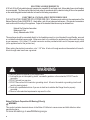 6
6
-
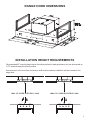 7
7
-
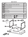 8
8
-
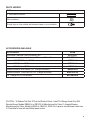 9
9
-
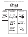 10
10
-
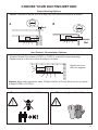 11
11
-
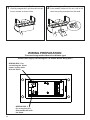 12
12
-
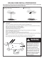 13
13
-
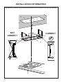 14
14
-
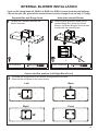 15
15
-
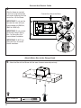 16
16
-
 17
17
-
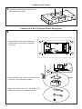 18
18
-
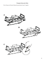 19
19
-
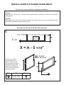 20
20
-
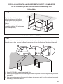 21
21
-
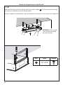 22
22
-
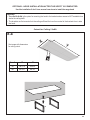 23
23
-
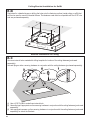 24
24
-
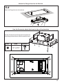 25
25
-
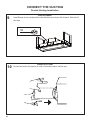 26
26
-
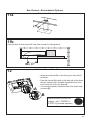 27
27
-
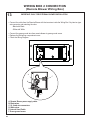 28
28
-
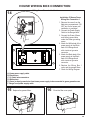 29
29
-
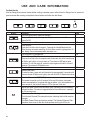 30
30
-
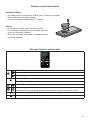 31
31
-
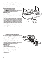 32
32
-
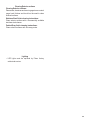 33
33
-
 34
34
-
 35
35
-
 36
36
-
 37
37
-
 38
38
-
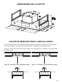 39
39
-
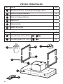 40
40
-
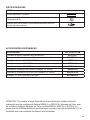 41
41
-
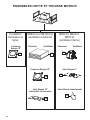 42
42
-
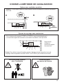 43
43
-
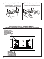 44
44
-
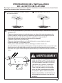 45
45
-
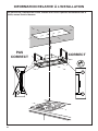 46
46
-
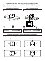 47
47
-
 48
48
-
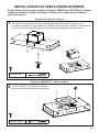 49
49
-
 50
50
-
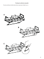 51
51
-
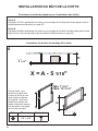 52
52
-
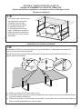 53
53
-
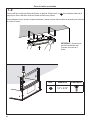 54
54
-
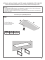 55
55
-
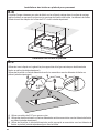 56
56
-
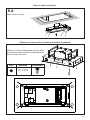 57
57
-
 58
58
-
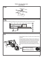 59
59
-
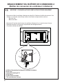 60
60
-
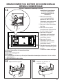 61
61
-
 62
62
-
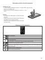 63
63
-
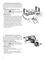 64
64
-
 65
65
-
 66
66
-
 67
67
-
 68
68
-
 69
69
-
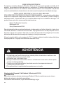 70
70
-
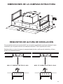 71
71
-
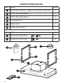 72
72
-
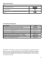 73
73
-
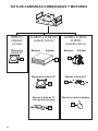 74
74
-
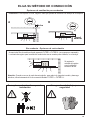 75
75
-
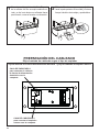 76
76
-
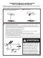 77
77
-
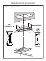 78
78
-
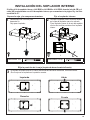 79
79
-
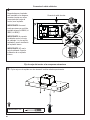 80
80
-
 81
81
-
 82
82
-
 83
83
-
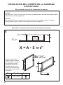 84
84
-
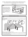 85
85
-
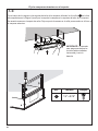 86
86
-
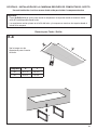 87
87
-
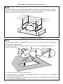 88
88
-
 89
89
-
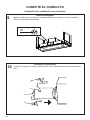 90
90
-
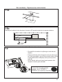 91
91
-
 92
92
-
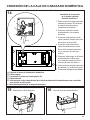 93
93
-
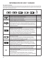 94
94
-
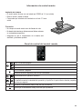 95
95
-
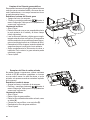 96
96
-
 97
97
-
 98
98
-
 99
99
-
 100
100


Faber Stratus 36 SS Guía de instalación
- Categoría
- Campanas de cocina
- Tipo
- Guía de instalación
- Este manual también es adecuado para
en otros idiomas
- français: Faber Stratus 36 SS Guide d'installation
- English: Faber Stratus 36 SS Installation guide
Artículos relacionados
-
Faber HILTIS36SSNB El manual del propietario
-
-
Faber Stratus 36 SS Guía de instalación
-
-
-
Faber Stratus 36 SS Guía de instalación
-
-
-
-