
TRANSPALETA ELÉCTRICA ............................................... 2
ELECTRIC PALLET TRUCK................................................67
MANUAL DE INSTRUCCIONES · INSTRUCTION MANUAL · GUIDE D’UTILISATION · BEDIENUNGSANLEITUNG ·
MANUALE D’USO · MANUAL DE INSTRUÇÕES · MANUAL DE INSTRUCŢIUNI · HANDLEIDING ·
ÜZEMELTETÉSI UTASÍTÁS · РУКОВОДСТВО ПО ЭКСПЛУАТАЦИИ · INSTRUKCJA OBSŁUGI
54396

Prefacio
Gracias por comprar nuestros productos.
El manual le mostrará la forma de utilizar correctamente la carretilla, así como el mantenimiento
preventivo y la operación de seguridad pertinentes. La carretilla sólo debe ser manejada por
profesionales bien formados y en ningún caso por personal que no trabaje. Los operadores deben
leer el manual antes de operar la carretilla.
Explicaciones sobre el manual
Con la continua actualización y mejora de los productos de nuestra empresa, puede encontrar un
ligera diferencia existente entre su portador y algunas introducciones en el manual.
Toda la información, las especificaciones y las ilustraciones del manual están vigentes en el
momento de la impresión y nuestra empresa se reserva el derecho de modificar las
especificaciones o el diseño de nuestros productos en cualquier momento sin previo aviso.
Señales de seguridad y sus correspondientes explicaciones
PELIGRO
Significa que su incumplimiento puede causar riesgo para la vida y/o daños importantes a la propiedad.
ADVERTENCIA
Respete estrictamente estas instrucciones de seguridad para evitar lesiones personales o
daños importantes en el equipo.
PRECAUCIÓN
Preste atención a las importantes instrucciones de seguridad.
NOTA
Preste atención a las instrucciones.
i
MANUAL DE INSTRUCCIONES
ES

Uso previsto
La carretilla está diseñada para transportar y elevar las cargas indicadas en la
placa de características. En particular nos referimos a:
• las normas de seguridad de su asociación profesional.
• De acuerdo con las disposiciones especiales para la conducción en vías públicas
especificadas por las especificaciones nacionales.
• Otras normativas locales.
Las normas para el uso previsto y aprobado de las carretillas industriales deben ser
respetadas en cualquier circunstancia por las personas responsables, especialmente por el
operador y el personal de servicio. El usuario, y no el fabricante, es responsable de cualquier
peligro derivado de aplicaciones no autorizadas por el fabricante.
Si desea utilizar la carretilla para aplicaciones no mencionadas en este manual, póngase primero en contacto
con su distribuidor autorizado.
No se podrá realizar ningún cambio, en particular ninguna modificación o adición, en el camión sin la
aprobación del fabricante.
Descripción técnica
• La carretilla consta de un robusto chasis de acero y se desplaza sobre una rueda de tracción y
2 ruedas de carga, lo que proporciona una buena estabilidad incluso con cargas elevadas.
• El camión se detendrá mediante un freno de servicio regenerativo y se mantendrá
en posición de estacionamiento mediante un freno de estacionamiento
electromagnético automático.
• La carga se eleva mediante un cilindro hidráulico que acciona un eje de elevación que
transmite el movimiento de elevación mediante una varilla de empuje a las ruedas de
carga.
• La empuñadura de control se utiliza para dirigir con suavidad y controlar la velocidad de
conducción, la elevación y el descenso, el frenado y la bocina sin cambiar la posición de la
mano. El largo eje del timón permite una dirección sin esfuerzo y una distancia segura al
camión. Un muelle devuelve la manivela de control siempre a una posición vertical que activa
el freno automáticamente.
• La serie F utiliza el nuevo diseño de chasis original de JBM, se puede dividir el marco delantero y
trasero. El F4 puede ser equipado con dos baterías de iones de litio, cuando uno es de baja
potencia, se puede quitar de lado sin esfuerzo, la batería resto todavía puede apoyar el camión
para trabajar. El F2/F3 puede ser equipado con una batería de iones de litio.
• Un controlador electrónico controla todas las funciones eléctricas y garantiza la seguridad.
• La estructura adoptada de un solo cilindro y dos varillas de conexión es sencilla y fiable, con una buena
elevación
• sincronismo.
• Un interruptor de llave asegura la carretilla contra el uso no autorizado.
• El diseño ergonómico de la carretilla garantiza un manejo seguro y sencillo.
Vistas esquemáticas
Este manual se utiliza para la operación y el
mantenimiento, los parámetros de detalle, el
tamaño y las especificaciones en el contexto es
sólo para referencia, los para metros reales
dependerá de los archivos de venta.
Manual de imágenes sólo para referencia, el
coche real prevalecerá, y no afectará el uso
manual. Manual de fotos sólo signo para uno de
los modelos en esta serie de modelos.
Utilizaremos la imagen de F4 o F2 como ejemplo
en lugar de la imagen de F3 en alguna sección, y
no afectará al uso manual.
Fig1154-00006OM

Obligaciones y responsabilidades del usuario del equipo
En el manual, el "usuario del equipo" se refiere a cualquier persona física o jurídica que utilice
directamente o que designe o autorice a otros a utilizar el transportista. En situaciones
especiales como el alquiler o la venta, el "usuario del equipo" representa a las partes
interesadas que deben asumir las obligaciones de explotación especificadas en las condiciones
contractuales celebradas entre el propietario del equipo y el correspondiente
usuarios. Los usuarios de los equipos deben garantizar el uso del portador sólo para los fines
especificados y eliminar oportunamente todos los peligros que puedan amenazar la vida y la salud
de los propios usuarios o de cualquier otro tercero, además de lo cual también deben cumplir
estrictamente las disposiciones de prevención de accidentes, otras disposiciones de tecnología de
seguridad y las directrices de operación, mantenimiento y reparación de los equipos, y asegurarse
de que todos los operadores lean seriamente y comprendan completamente el contenido de las
instrucciones de operación.
En caso de que se produzca cualquier violación de las instrucciones de funcionamiento, la garantía
de calidad de nuestra empresa quedará automáticamente invalidada, y nuestra empresa no
asumirá ninguna de las responsabilidades por las pérdidas resultantes de cualquier funcionamiento
no estándar del equipo implementado por cualquier cliente, usuario del equipo o cualquier tercero
sin la autorización del departamento de servicio al cliente de nuestra empresa.
Modificación
La modificación no autorizada de la carretilla puede provocar lesiones o la muerte.
No puede eliminar, desactivar o modificar ningún dispositivo de seguridad.
Excepción: Sólo en el caso de que el fabricante de la carretilla deje de operar y no haya un
sucesor en el interés de la empresa, el usuario podrá disponer de una modificación o alteración de
una carretilla industrial motorizada, siempre y cuando el usuario
a) dispone que la modificación o alteración sea diseñada, probada y
ejecutada por un ingeniero o ingenieros expertos en carretillas
industriales y su seguridad.
b)mantiene un registro permanente del diseño, las pruebas y la aplicación de la modificación o
alteración.
c) aprueba y realiza los cambios pertinentes en la(s) placa(s) de capacidad, las calcomanías, las etiquetas y el
funcionamiento
manual.
d) coloca en la carretilla una etiqueta permanente y fácilmente visible en la que se indique la forma
en que se ha modificado o alterado la carretilla, junto con la fecha de la modificación o alteración y
el nombre y la dirección de la organización que ha realizado esas tareas.
Cargas de viento
Las fuerzas del viento pueden afectar a la estabilidad de una carretilla cuando se trata de subir, bajar y
transportar cargas con grandes
superficies .
Las cargas ligeras deben asegurarse especialmente cuando están sometidas a las fuerzas del
viento. Esto evitará que la carga se deslice o caiga.
Detenga el camión en ambos casos.

Índice de contenidos
Pg.
A 1.1 Placas de características y etiquetas de alarma...................................................................A1
B Operación.......................................................................................................................................... B1
1.1 Especificación de seguridad de uso............................................................................................. B1
1.1.1 Normas EN................................................................................................................................... B3
1.1.2 Condiciones de aplicación......................................................................................................... B3
1.1.3 Estabilidad.................................................................................................................................... B4
1.2 Visualización y manipulación........................................................................................................B5
1.2.1 Resumen del camión.................................................................................................................. B5
1.2.2 Mando de control.........................................................................................................................B8
1.2.3 Interruptor de llave.................................................................................................................... B10
1.2.4 Instrumento de visualización................................................................................................... B10
1.3 Uso y funcionamiento del camión.............................................................................................. B11
1.3.1 Preparación para el uso........................................................................................................... B11
1.3.2 Puesta en servicio.....................................................................................................................B12
1.3.3 Arranque del camión.................................................................................................................B13
1.3.4 Marcha, dirección y frenado.................................................................................................... B14
1.3.5 Recogida de mercancías......................................................................................................... B18
1.3.6 Aparcar el camión de forma segura....................................................................................... B19
1.3.7 Direcciones de conducción......................................................................................................B20
1.3.8 Cargando....................................................................................................................................B20
1.3.9 Utilización de la carretilla en una pendiente......................................................................... B21
1.3.10 Transporte por camión........................................................................................................... B23
1.3.11 Cómo quitar un camión roto.................................................................................................. B24
1.3.12 Funcionamiento de la carretilla sin su propio sistema de tracción................................. B25
C Uso y mantenimiento de la batería...............................................................................................C1
1.1 Carga de la batería.........................................................................................................................C1
1.1.1 Precauciones................................................................................................................................C1
1.1.2 Carga de la batería con un cargador externo......................................................................... C1
1.1.3 Tipo de batería y dimensiones&Tiempo de carga................................................................. C4
1.2 Extracción e instalación de la batería..........................................................................................C4
D Mantenimiento.................................................................................................................................. D1
1.1 Mantenimiento de camiones......................................................................................................... D1
1.2 Tabla de mantenimiento................................................................................................................ D5
1.3 Instrucciones de mantenimiento...................................................................................................D8
1.3.1 Preparar el camión para el mantenimiento y las reparaciones............................................D8
1.3.2 Retire la tapa................................................................................................................................D8
1.3.3 Cómo añadir aceite hidráulico...................................................................................................D9
1.3.4 Cómo añadir grasa......................................................................................................................D9
1.3.5 Comprobación de los fusibles................................................................................................... D9
1.4 Puesta en servicio.......................................................................................................................... D9
1.5 Desmantelamiento final, eliminación........................................................................................... D9
1.6 Sustitución de neumáticos............................................................................................................. D9
E Datos técnicos....................................................................................................................................E1

Índice de contenidos
Pg.
F Baterías de iones de litio.................................................................................................................. F1
1 Información sobre la conformidad de las baterías de iones de litio..........................................F2
2 Es necesario respetar las siguientes directrices..........................................................................F2
3 Uso previsto....................................................................................................................................... F2
4 Uso indebido razonablemente previsible...................................................................................... F2
5 Accesorios.......................................................................................................................................... F3
6 Placa de identificación de la batería de iones de litio................................................................. F3
7 Seguridad y advertencia.................................................................................................................. F4
8 Peligro de batería defectuosa o desechada................................................................................. F5
9 Transporte.......................................................................................................................................... F6
10 Envío de baterías defectuosas...................................................................................................... F7
11 Instrucciones para la eliminación................................................................................................. F7
12 Cargando......................................................................................................................................... F8
13 Almacenamiento............................................................................................................................. F8
14 Problemas comunes y soluciones............................................................................................... F9
15.Servicio.............................................................................................................................................. F10

A1.1 Placas de características y etiquetas de alarma
Que las placas de identificación de un camión fijen su carrocería principal y las etiquetas de alarma
pegadas en su exterior
cubierta.
En caso de que alguna placa de identificación o etiqueta de alarma se pierda o se dañe, por
favor, realice la sustitución inmediatamente o contacte con el departamento de ventas o el
agente correspondiente de nuestra empresa cuando sea necesario.
En las placas de características figuran datos como el modelo del producto, el número de
serie, la fecha de fabricación, la capacidad nominal de elevación de la carga, la altura de
elevación, la distancia entre ejes de la carga y el peso muerto.
Etiquetas alarmantes
Puerto de aceite
hidráulico
No apoyarse en
la etiqueta de la
transpaleta
Etiqueta
antipinchazos
para las manos
Leer la etiqueta
del manual de
instrucciones
A1
Fig0000-00030OM
Fig0000-00184OM
Fig0000-00178OM
Fig0000-00123OM

2
3
4
12
13
5
9
8
0
11
14
15
Placa de características
1
Elevación
Retire la carga antes de elevar la transpaleta.
Desconecte la fuente de alimentación.
Fije las eslingas en las posiciones identificadas por el símbolo del gancho.
PELIGRO
El personal no debe situarse debajo o cerca de la carretilla cuando ésta se esté elevando.
A2
Artíc
ulo
Descripción
2
TIPO DE MODELO
3
NÚMERO DE SERIE
4
FECHA DE
FABRICACIÓN
5
ALTURA DE ELEVACIÓN
8
VOLTAJE DE LA
BATERÍA
9
POTENCIA NOMINAL DE
ACCIONAMIENTO
10
PESO MÁXIMO DE LA
BATERÍA
11
PESO MÍNIMO DE LA
BATERÍA
12
CAPACIDAD
CALIFICADA
13
CENTRO DE CARGA

Operación
1.1 Especificación de seguridad de uso
Fig0000-00120OM
• Temperatura ambiente media
para
servicio continuo: +25℃;
• Temperatura ambiente máxima,
a corto plazo (hasta 1h): +
40℃;
• La temperatura ambiente
más baja para las carretillas
destinadas a ser utilizadas
en
condiciones interiores normales:
+5℃; Temperatura ambiente
más baja para carretillas
destinadas a ser utilizadas en
condiciones normales de exterior:
- 20℃;
NOTA
No utilice el camión
en
agua de lluvia.
No utilices el camión en no
posición.
Se requiere un equipamiento especial y una autorización si la carretilla se va a utilizar constantemente
en condiciones de fluctuaciones extremas de temperatura o humedad del aire. Recomendamos con
medidas especiales para la carretilla o comprar la carretilla para el almacenamiento en frío. En caso
de duda, póngase en contacto con el servicio de atención al cliente del fabricante.
NOTA
Rango de temperatura de carga de la batería de litio: 5~40℃ ,0℃ por debajo del entorno de baja
temperatura en las condiciones de carga a gran escala causará daños a la batería; Rango de
temperatura de descarga: -20℃ ~55℃ , la capacidad de descarga a baja temperatura (-20℃ ~0℃ )
que a temperatura ambiente puede reducirse en comparación con la normal, es normal; la batería
puede ser de 40℃ ~55℃ de temperatura ambiente, pero la temperatura ambiente de la batería es
demasiado alta, especialmente en el entorno de la batería de alta temperatura a largo plazo, acelerará
el envejecimiento del material de la batería, acortar la vida de la batería, no se recomienda para el
uso a largo plazo a esta temperatura. La temperatura ambiente que exceda el rango anterior de
temperatura de carga y descarga puede afectar negativamente al rendimiento de la batería o dañar,
puede acortar en gran medida la vida de la batería, debe evitarse a la temperatura anterior.
B1
i
i
B

Fig0000-00121OM
• Evitar el uso del camión por
personal que no trabaja.
• No te subas al camión.
• No lleves o levantes a las
personas por el camión.
No utilice el camión en lugares
resbaladizos
de la carretera.
(como las superficies de las
carreteras con manchas de
aceite o nieve residual o
aquellas congeladas )
No lleves la mercancía a cuestas
pendiente para evitar que las
mercancías
para que no se deslice.
NOTA
Condiciones de funcionamiento de la superficie de la carretera: el camión debe circular por una carretera sólida,
plana, nivelada y pavimentada
superficies (incluyendo tanto la carrera como el levantamiento).
Fig0000-00122OM
No dejes el camión antes
de
se aparca como está
regulado.
• No utilice el camión cuando
cualquier
El personal que no trabaja se
encuentra en la zona
peligrosa.
• No te distraigas cuando uses
el camión.
• No te distraigas cuando uses
el camión.
No coloques ninguna parte de
su cuerpo en cualquier
parte móvil de la
carretilla para evitar ser
aprisionado.
B 2
i

1.1.1 Normas EN
1.1.2 Condiciones de aplicación
ADVERTENCIA
• El extintor debe estar equipado en el lugar de trabajo. Los usuarios pueden elegir un
camión equipado con extintor. El conductor y el gerente deben estar familiarizados con la
posición del extintor y el método de aplicación.
• Utilice la bandeja para transportar objetos pequeños, no los coloque directamente en el tenedor.
•
Después de apagar, el freno funciona y el camión no puede ser remolcado(arrastrado).
•
Lave el interior de la carretilla, no la coloque al aire libre y expuesta a la lluvia.
•
Antes de desmontar o reparar la carretilla, levante primero la batería de la carretilla.
Nivel sonoro continuo: 74 dB(A)
según la norma EN 12053, tal como se estipula en la norma ISO 4871
El nivel sonoro continuo es un valor promediado según la normativa estándar, teniendo en cuenta
el nivel de presión sonora durante la conducción, la elevación y el ralentí. El nivel de presión sonora
se mide en el oído.
Compatibilidad electromagnética (CEM)
El fabricante confirma el cumplimiento de los valores límite de emisión electromagnética e
inmunidad a las interferencias, así como las pruebas de descarga de electricidad estática según la
norma EN 12895 y las referencias a otras normas contenidas en ella.
Los componentes eléctricos o electrónicos y su disposición sólo pueden ser modificados después de
Se ha obtenido la aprobación del fabricante.
Requisitos de las condiciones de trabajo:
– La altitud máxima de funcionamiento del camión es de hasta 2000 m.
– Los camiones sólo pueden funcionar en zonas de trabajo adecuadamente iluminadas para evitar
lesiones. En caso de que la luz sea insuficiente, es necesario un equipo de iluminación adicional
para garantizar que el conductor pueda ver correctamente.
Si tiene que circular por una pendiente, los desniveles deben ser inferiores al A% a plena carga, o al B%.
sin carga. (Para el valor de A y B, consulte la Gradabilidad en los datos técnicos)
B3

1.1.3 Estabilidad
La estabilidad está garantizada si su carretilla se utiliza correctamente de acuerdo
con su finalidad. Las razones más comunes para una pérdida de estabilidad de la
carretilla son:
• Paradas de emergencia o giros bruscos
• Conducir con una carga elevada o con un dispositivo de manipulación de cargas
• Girar el vehículo en una pendiente o atravesarla
• Subir o bajar una pendiente con la carga orientada hacia abajo
• Conducir con una carga amplia
• Llevar una carga oscilante
• Conducir cerca del borde de una rampa o subir escalones
• Inclinación del mástil hacia delante
mientras se lleva una carga elevada
• Conducción en superficies irregulares
• Sobrecarga del camión
• Transportar cargas voluminosas con vientos fuertes
• Cuando se transporta un líquido, su centro de masa dentro del contenedor puede desplazarse debido a
la fuerza de inercia (como al arrancar, frenar o girar)
B 4

1.2.1 Visión general del camión
1.2 Visualización y manipulación
F4
112
11
13 10
2
4
10
5
6
78 9
1
Mango de control
8
Rueda motriz
2
Cubierta de la manija
de control
9
Batería de iones de litio
3
Buzones de
documentos
10
Ruedas de carga
4
Unidad hidráulica
11
Horquillas
5
Cubierta hidráulica
12
Enchufe de alimentación e
instrumento de visualización
6
Capó de conducción
13
Cubierta superior
7
Controlador
B5

F3
1
11
2
12
3
4
5
10
6
7
8
9
Fig1154-00021OM
1
Mango de control
8
Rueda motriz
2
Cubierta de la manija de
control
9
Batería de iones de litio
3
Cubierta superior
10
Ruedas de carga
4
Unidad hidráulica
11
Brazos de la horquilla
5
Rueda (opcional)
12
Enchufe de alimentación e
instrumento de visualización
6
Capó de conducción
7
Controlador
B 6

F2
1
11
12
2
3
4
5
10
6
7
8
9
Fig1154-00021OM
1
Mango de control
8
Rueda motriz
2
Cubierta de la manija de
control
9
Batería de iones de litio
3
Cubierta lateral
10
Ruedas de carga
4
Unidad hidráulica
11
Brazos de
la
horquilla
5
Caster
12
Enchufe de alimentación e
instrumento de visualización
6
Capó de conducción
7
Controlador
B7

1.2.2 Mango de control
F4
Fig1154-00005OM
11
Interruptor de llave
Conectar e interrumpir la corriente de control.
12
Lámpara de
indicación de fallos
La luz roja permanece encendida en condiciones normales, el parpadeo
muestra el fallo
estado del camión. Muestra el estado de error de la carretilla ( ver
el capítulo código de error)
13
Botón de la bocina
Envíe señales de advertencia sonoras.
14
Botón de elevación
Eleva el dispositivo de carga. Cuando la batería está
consumido alrededor del 85%, la función de elevación se bloqueará.
15
Botón inferior
Baja el dispositivo de carga.
16
Interruptor de
accionamiento
Controla el sentido de la marcha y la velocidad
17
Conmutador de
velocidad de avance
Si la palanca de mando está colocada en la zona de freno (B), y se pulsa
Si el interruptor de velocidad de arrastre y el interruptor de
accionamiento se encuentran al mismo tiempo, el vehículo se moverá a
baja velocidad.
18
Reversa de
emergencia
cambiar
Al pulsar este interruptor, el vehículo comienza a circular en el
dirección opuesta.
B 8

F3/F2
11
Interruptor de llave
Conectar e interrumpir la corriente de control.
12
Lámpara de indicación
de fallos
La luz roja permanece encendida en condiciones normales, el
parpadeo muestra el
estado de error de la carretilla. Muestra el estado de error de la
carretilla ( ver el capítulo código de error)
13
Conmutador de
velocidad de avance
Si la palanca de mando está colocada en la zona de frenado (B), y se
presiona el botón de arrastre
interruptor de velocidad y el interruptor de conducción al
mismo tiempo, entonces el vehículo se moverá a baja
velocidad.
14
Botón de elevación
Eleva el dispositivo de carga. Cuando la batería está
consumido alrededor del 85%, la función de elevación se bloqueará.
15
Botón inferior
Baja el dispositivo de carga.
16
Interruptor de
accionamiento
Controla el sentido de la marcha y la velocidad
17
Botón de la bocina
Envíe señales de advertencia sonoras.
18
Reversa de
emergencia
cambiar
Al pulsar este interruptor, el vehículo comienza a circular en el
dirección opuesta.
B9

1.2.3 Interruptor de llave
1.2.4 Instrumento de visualización
Interruptor de llave
Conectar e interrumpir la corriente de control.
• Cuando la llave gire a la marcha "OFF", se
interrumpirá la corriente de control de la
carretilla;
• Cuando la llave gire a la marcha "ON", se
conectará la corriente de control del camión.
NOTA
Sacar el interruptor de llave de una carretilla
elevadora antes de salir puede evitar que la
carretilla se ponga en marcha
accidentalmente.
Cuando la carretilla se pone en marcha,
se enciende el indicador de las cuatro
luces. Cuando se enciende el único
indicador luminoso residual (4), significa
que la capacidad de la carretilla es baja y
debe cargarse inmediatamente.
ADVERTENCIA
Cuando el único indicador luminoso
residual (4) parpadee, la carretilla estará
apagada.
NOTA
Sólo en el estado estático de F4 se puede
observar con precisión la capacidad de la
batería a través de cuatro indicadores
luminosos .
NOTA
Es normal que el indicador luminoso siga
encendido cuando el interruptor de llave está
apagado y el enchufe de alimentación no está
extraído.
432 1
Fig1154-00002OM
B 10
i
Fig0000-00098OM
i
i

1.3.1 Preparación para el uso
1.3 Uso y funcionamiento del camión
ADVERTENCIA
Las siguientes son las operaciones de inspección y preparación que deben realizarse antes de que la
carretilla se ponga en uso diario.
Tabla 1. Cuadro de las inspecciones diarias de
los operadores
Lista de comprobación diaria
del operador
Fecha
Operador
Camión No.
No.
Departamento
Tiempo de ejecución
Lectura del contador
Cuadro 1: Cuadro de inspecciones diarias por operadores es sólo un cuadro de muestra de las inspecciones
diarias de
operadores, y puede ajustarse en función de las necesidades específicas.
B11
Elementos de control diario
O.K.(√)
Nota:
Comprobación de fugas de líquido
Compruebe si hay arañazos, deformaciones o grietas.
Comprobar el estado de la calcomanía
Compruebe el movimiento suave de las ruedas.
Compruebe el funcionamiento del freno de
emergencia activando el enchufe de
alimentación.
Comprobar la función de frenado del brazo de la caña
de timón
Compruebe las funciones de elevación y
descenso accionando los botones.
Compruebe si todos los tornillos y tuercas están bien
apretados.
Compruebe el arrastre vertical del camión.
Compruebe la instalación de iones de
litio, asegurándose de no dañar los
cables de la batería.
Recarga la batería de iones de litio

1.3.2 Puesta en servicio
ADVERTENCIA
La carretilla debe ser mantenida regularmente por ingenieros o técnicos de mantenimiento cualificados
que han superado la formación de y también han sido autorizados por el fabricante.
La carretilla sólo debe funcionar con la corriente de la batería.
Para preparar el camión para su funcionamiento después de la entrega o el transporte, se deben realizar
las siguientes operaciones:
Compruebe que el equipo está completo.
Si es necesario, instale la batería. Asegúrese de que el cable de la batería no esté dañado.
• Carga la batería.
• Compruebe si hay fugas de líquido.
• Compruebe el funcionamiento de los frenos.
• Compruebe la función de elevación y descenso.
• Compruebe la función de conducción.
• Compruebe el funcionamiento de la dirección.
• Ahora se puede arrancar el camión, véase 1.3.3 Arranque del camión
ADVERTENCIA
La carretilla sólo debe funcionar con una batería de iones de litio.
NOTA
Si la carretilla se entrega en varias partes, el montaje y la puesta en marcha deben ser realizados
únicamente por personal formado y autorizado.
Aplanamiento de la rueda
Si la carretilla ha estado aparcada durante mucho tiempo, las superficies de las
ruedas pueden tender a aplanarse. Este aplanamiento tiene un efecto negativo en la
seguridad y la estabilidad del camión. Una vez que el camión haya recorrido cierta
distancia, el aplanamiento desaparecerá.
B 12
i

1.3.3 Arranque del camión
Realice una comprobación antes del funcionamiento y asegúrese de que todas las funciones y
estados son normales (véase el apartado 1.3.1 Preparación para el uso).
Antes de empezar, pulse el botón de la bocina (3) para F4 o (4) para F2/F3 y asegúrese de que no hay gente
alrededor.
1.Enganche la clavija de alimentación (1);
2.Abra el interruptor de llave (2) para arrancar el camión.
4
B13
F4
3
2
1
Fig1154-00003OM
F2/F3

1.3.4 Marcha, dirección y frenado
Fig1154-00016OM
M
1
Adelante
Hacia atrás
Ejecutar
Coloque la palanca de control en la zona de marcha (M), coloque el interruptor de
accionamiento (1) en la dirección deseada (hacia adelante o hacia atrás). Controle la
velocidad de desplazamiento con el interruptor de accionamiento (1) (cuanto mayor sea el
ángulo de giro, mayor será la velocidad correspondiente).
NOTA
Cuando utilice la carretilla en una rampa o en una carretera irregular, levante las horquillas de la carretilla para
evitar
su parte inferior de chocar con la superficie de la carretera.
B 14
i

M
Fig0000-00350O
Fig0000-00349OM
El conductor debe caminar por delante de la carretilla y mantenerse en la parte delantera lateral de
la carretilla cuando se desplace. Una mano sujeta el asa y acciona el interruptor de marcha con el
pulgar. Observe siempre la dirección de desplazamiento y guíe la carretilla. O sujete el asa con
ambas manos y empuje la carretilla hacia delante.
PRECAUCIÓN
• El operador debe llevar botas de protección.
• Al entrar en la zona estrecha como el ascensor, primero hay que coger la horquilla.
• Viajar según la ruta regulada. Mantener la carretera limpia y sin resbalones.
Viaje lento
Cuando se aplica el botón de velocidad de desplazamiento lento y el interruptor de accionamiento en la
zona de frenado (B), la carretilla
viaja a velocidad y aceleración reducidas.
Procedimiento:
• Pulse el botón de velocidad de desplazamiento lento (1) para F4 o (4) para F2/F3 y el
interruptor de accionamiento (2) en la zona de frenado (B).
• La carretilla puede manejarse con una palanca de control (3) (por ejemplo, en zonas
congestionadas/sede de viaje).
• Coloque el interruptor de accionamiento (2) en la dirección deseada (hacia adelante o hacia atrás).
• El camión viaja a baja velocidad.
F2/F3
22
3
4
B15
Fig1154-00003OM
3
2
1
2
F4

A la derecha
Izquierda
Fig1154-00020OM
Dirección
Mueve la mano de control hacia la izquierda o la derecha.
3.Frenado
Freno de funcionamiento mecánico
La carretilla se frena cuando se suelta
la palanca de mando.
El freno mecánico se activa cuando el
La caña de timón está colocada en el área B).
PRECAUCIÓN
Si la manija de control se mueve lentamente
hacia la posición de freno, identifique la
causa y rectifique el fallo. Si es necesario,
sustituya el muelle.
Freno regenerativo
Suelte el interruptor de accionamiento. El
interruptor de accionamiento volverá
automáticamente a la posición inicial y el
vehículo comenzará a entrar en el estado
de frenado regenerativo. Cuando se
desacelere a <1 km/h, el freno
electromagnético hará que el motor se
detenga.
B 16
B
B
Fig1154-00016OM

Frenado en reversa
Se puede frenar cambiando el sentido de
la marcha.
Pulse el interruptor de marcha atrás en
sentido contrario hasta que la carretilla
se detenga, entonces suelte el
interruptor de marcha.
PRECAUCIÓN
Abra el interruptor del accionamiento; si el
interruptor del accionamiento no puede
volver rápidamente a la posición inicial o se
reinicia muy lentamente, identifique la causa
y subsane el fallo.
Freno de estacionamiento
El freno mecánico se aplica
automáticamente cuando el camión se
detiene.
Enchufe de alimentación
Si se extrae el enchufe de alimentación,
se interrumpen todas las funciones de
propulsión eléctrica.
B17
Fig1154-00006OM

1.3.5 Recogida de mercancías
Mantenga pulsado el botón de elevación hasta alcanzar la
altura de elevación deseada
Bajar las horquillas de la paleta hasta el fondo pulsando el
botón de bajada.
Fig1154-00012OM
ADVERTENCIA
La falta de arreglo y fijación de las mercancías puede provocar accidentes.
NOTA
Para no acortar la vida útil del cilindro de aceite, procure no elevar las horquillas al estado más alto
para su elevación.
B 18
i

1.3.6 Estacionamiento seguro del camión
Conduzca el camión a una zona segura o a una
zona designada.
Bajar las horquillas hasta el fondo;
Apague el interruptor de la llave(1) ;
Saque el enchufe de alimentación (2);
ADVERTENCIA
• En caso de que sea necesario que los
operarios abandonen la carretilla,
aunque sea por un momento, la
carretilla también debe estar bien
aparcada, tal y como se especifica.
• Los camiones no pueden aparcar en
las pistas.
• Las horquillas deben bajar hasta
el fondo.
B19
Fig0000-00071OM
2
1
Fig1154-00003OM

1.3.7 Direcciones de conducción
1.3.8 Carga
Los sentidos de marcha de la carretilla son
hacia delante (1) y hacia atrás (2).
•Acércate a la carga con cuidado.
•Ajuste la altura de las horquillas hasta
que puedan introducirse fácilmente en
la paleta.
•Introduzca las horquillas bajo la carga.
•Si la carga es más corta que las
horquillas, coloque las horquillas de
manera que la parte delantera de la
carga sobresalga unas cuantas
veces.
centímetros, para evitar la interferencia
con la carga inmediatamente anterior.
•Eleve la carga unos centímetros por
encima de su soporte.
•Aleje el camión de la pila o de las
cargas vecinas, con cuidado y en
línea recta.
Transporte de cargas
Lleve siempre la carga en el sentido de la
marcha (R) para tener la mejor visibilidad.
Cuando lleve una carga en una
pendiente, ascienda o descienda
siempre con la carga cuesta arriba.
Nunca conduzca lateralmente por una
pendiente ni realice un giro en U.
La marcha atrás (F) debe utilizarse
únicamente para la descarga. Dado que la
visibilidad es reducida cuando se viaja en
esta dirección, conduzca sólo a una
velocidad muy baja.
B 20
1
2
Fig0000-00072OM
Fig0000-00078OM
R
F

1.3.9 Utilización de la carretilla en una
pendiente
Descargando
Conduzca con cuidado el camión
hasta el lugar deseado.
Conduzca con cuidado el camión hasta
la zona de descarga.
Bajar la carga hasta que los brazos de la
horquilla estén libres de la paleta.
Retroceda la carretilla en línea recta.
Eleve las horquillas a la altura
adecuada.
PRECAUCIÓN
Si el campo de visión es pobre, pida a un guía
asistencia.
NOTA
El uso incorrecto de la carretilla en
las pendientes supone un esfuerzo
para el motor de tracción, los frenos y
la batería.
Tenga especial cuidado cerca de las
pendientes: No intentes nunca una
pendiente con una inclinación superior a
la especificada en la ficha técnica de la
carretilla. Asegúrese de que el suelo
esté seco con una superficie
antideslizante y que la ruta esté
despejada.
Pendientes ascendentes
Suba siempre las pendientes en sentido
inverso, con la carga hacia arriba. Sin
carga, se recomienda ascender las
pendientes hacia delante.
Pendientes descendentes
La bajada de pendientes debe
hacerse siempre hacia delante, con la
carga hacia arriba. Sin carga, se
recomienda descender
pendientes hacia delante. En todos los
casos, circule a una velocidad muy baja y
frene muy gradualmente.
B21
Fig0000-00085OM
i
Fig0000-00141OM
Fig0000-00142OM

PELIGRO
Riesgo para la vida y/o riesgo de daños
importantes en el equipo.
Nunca estacione el camión en una pendiente.
Nunca haga un giro en U ni tome atajos en
una pendiente. En una pendiente, el operador
debe conducir muy lentamente.
Empezar en una pendiente
Si tiene que parar y luego empezar en
pendiente, proceda como sigue:
• Deténgase en la pendiente pisando el
acelerador en sentido contrario hasta
que la máquina se detenga.
• Vuelva a poner el acelerador en
posición neutra y, a continuación,
suelte el botón de control del
acelerador para aplicar el freno de
estacionamiento.
• Paravolver a arrancar, pulse el botón
del acelerador para la dirección
deseada.
• El camión se moverá.
NOTA
El uso incorrecto de la carretilla en las
pendientes supone un esfuerzo para el motor
de tracción, los frenos y la batería.
B 22
i

1.3.10 Transporte por camión
Fig1154-00022OM
Fijar correctamente la carretilla para evitar que se mueva al utilizar
camión o remolque.
Procedimiento:
• Aparque el camión de forma segura.
• Coloque la correa tensora (1) alrededor del
camión y fíjela a las anillas de sujeción del
vehículo de transporte.
• Utilice cuñas para evitar que el camión se mueva.
• Apriete la correa tensora (1) con el
tensor.
ADVERTENCIA
• El camión o el remolque deben tener
anillos de sujeción.
• Utilice cuñas para evitar el camión.
• Utilizar únicamente correas de tracción
o de sujeción de buena resistencia
nominal.
La transpaleta está diseñada únicamente para la manipulación de materiales a corta distancia y es inadecuada
para
transporte de larga distancia. Si es necesario, la transpaleta debe transportarse utilizando un
dispositivo de elevación o una plataforma para colocarla en el camión o el remolque. Antes de la
operación, fije la transpaleta firmemente en el vehículo de transporte con correa, y bloquee la rueda
para evitar el movimiento relativo durante el transporte.
B23
1
Fig1154-00014OM

1.3.11 Cómo retirar un camión roto
No está permitido remolcar la
carretilla elevadora en el suelo
directamente cuando la carretilla está
averiada o dañada ya que el
El freno del camión está cerrado en
circunstancias normales. Se deben
utilizar vehículos adecuados para retirar
los camiones rotos.
NOTA
Utilice únicamente equipos de transporte con suficiente
capacidad de carga.
•El peso de la carga incluye el peso neto
del camión (incluido el peso de la batería)
y el palé de madera.
•El palé o la caja de madera debe ser lo
suficientemente grande y fuerte como
para soportar el peso del camión.
•Preste atención a las cuchillas de las
horquillas cuando eleve la carretilla
sobre el palé, para evitar lesiones
causadas por las horquillas.
Siga los pasos indicados y estacione el
vehículo correctamente.
Asegúrese de que las horquillas están
alineadas con el palet, muévase lentamente y
deténgase después de introducir las horquillas
hasta el
paleta como sea posible.
PRECAUCIÓN
Opere en un terreno abierto y nivelado y
preste atención a las condiciones del suelo
cuando eleve y baje la paleta para evitar que
la carretilla vuelque.
Cuando transportes el camión, asegúrate de
que está totalmente asegurado y toma
medidas de precaución contra el mal
tiempo.
B 24
i
Fig1154-00018OM

1.3.12 Operar la carretilla sin su propio sistema de tracción
Si hay que mover la carretilla después de que
una avería la haya dejado inmóvil, proceda
como sigue:
• Tire de la clavija de alimentación.
• Ponga el interruptor de la llave en "OFF" y
retire la llave. Evite que el camión se desplace.
•Retira la tapa.
•Atornille dos tornillos(1), M4*35mm hasta
que la carretilla pueda moverse (sin acción
de frenado).
•Tras depositar la carretilla en el lugar de
destino, desenrosque dos tornillos(1)
.
•Se restablece la acción de frenado.
ADVERTENCIA
Este modo de funcionamiento no está
permitido cuando se negocian inclinaciones y
pendientes.
B25
Fig0000-00067OM

1.1.1 Precauciones
1.1.2 Carga de la batería con un cargador externo
CUso y mantenimiento de la batería
1.1 Carga de la batería
• El camión debe estar aparcado en un lugar sombreado y ventilado;
• No coloque objetos metálicos sobre la batería;
• Todas las piezas de conexión del cable y del enchufe deben ser inspeccionadas en cuanto a
daños evidentes antes de la carga;
• Los enchufes de alimentación de las pilas deben estar siempre secos y limpios.
• La superficie de la batería debe estar despejada para garantizar que sea suficiente.
• El conector de carga debe estar seco y limpio cuando se utilice.
• Está prohibido cargar en la zona de no carga;
• No se modifican los vehículos;
• No utilice enchufes de carga irregulares;
• La altura neta de la zona de carga deberá ser superior a 5 m, y la distancia de seguridad con
respecto a otras zonas deberá ser superior a 5 m.
Procedimiento de cobro:
• Aparque el camión de forma segura;
• Tire del enchufe de alimentación y extraiga la batería de iones de litio según el apartado
1.2 Extracción e instalación de la batería;
• Inspección visual del cargador externo;
• Si no está dañado, inserte el enchufe de carga del cargador en el enchufe de la batería;
• Inserte el enchufe del cargador en una toma de corriente adecuada.
NOTA
El indicador de carga se ilumina, la batería se está
cargando. Indicador LED de carga: Rojo de carga
Indicador LED de carga: Verde cargado
ADVERTENCIA
Cargador 24V/4A potencia máxima de entrada 300W .
Por favor, aplique estrictamente los datos anteriores para evitar daños en el equipo y riesgos accidentales
como el fuego.
C1
i

F4
Fig1154-00009OM
F2
F3
C 2

La batería está completamente cargada después de
5,0 horas de carga a 100 ~ 240V AC;
La batería puede funcionar de forma continua
durante 2,0 horas en un estado de carga
completa.
C3
5.0h
Fig1154-00010OM
2.0 h
Fig1154-00019OM

1.1.3 Tipo de batería, dimensiones y tiempo de carga
Los tipos y dimensiones de las baterías son los siguientes:
Tipo de
pliegue
Tensión/
Calificación
capacidad
Dimensione
s
Cargad
or
Tiempo de
carga
F2/F3/F4
24V/20Ah
290*238*76
4A
5h
1.2 Extracción e instalación de la batería
Aparque la carretilla de forma segura como se describe en el capítulo B sección 1.3.6 y desconecte la corriente
antes de desmontarla
e instalación de la batería.
Pasos para la extracción e instalación
de la batería: Para el F4:
• Abra la tapa (1)y saque el asa de
montaje del enchufe (2);
• Sujete el asa de la batería y extraiga la
batería de iones de litio de un lado;
ADVERTENCIA
Antes de retirar la batería, asegúrese de que
el vehículo está completamente apagado.
C 4
F4
2
1
Fig1154-00007OM

Para F3:
• Abra la tapa superior(1) y extraiga el asa de
montaje del enchufe(2);
• Sujete el asa de la batería y retire la
batería de iones de litio de la base de la
batería;
Para F2:
• Pulse el botón y abra la tapa lateral(1) ;
• Extraiga el asa de montaje del tapón(2)
• Sujete el asa de la batería y retire la
batería de iones de litio de la base de la
batería;
C5
1
2
F3
2
F2
2
1

Mantenimiento
1.1 Mantenimiento de camiones
Sólo mediante la realización periódica de trabajos de mantenimiento de la carretilla se puede
garantizar el uso sostenible y fiable de la misma.
Sólo las personas que reciben una formación profesional y son aprobadas como cualificadas
pueden ser competentes en las distintas operaciones de mantenimiento de los equipos. Si
tiene la intención de realizar el mantenimiento de forma independiente, se recomienda que el
personal de mantenimiento reciba formación in situ por parte del representante de servicio del
proveedor del equipo.
Anuncio de seguridad:
• Sustitución de neumáticos: por favor, realice la sustitución de los neumáticos con los designados por el
fabricante, ya que los neumáticos no calificados pueden influir en las propiedades y la estabilidad de los
productos.
• Es inadecuado limpiar el camión con un líquido inflamable.
• Asegúrese de que la fuente de alimentación ha sido completamente desconectada antes de
la operación de mantenimiento.
Desmantelamiento del camión industrial:
• Si se requiere que esté estacionado por más de un mes, el camión debe colocarse en un
ambiente seco y libre de heladas.
• Limpia el camión con cuidado.
• Cubra las partes metálicas sin pintar con una fina capa de aceite o grasa.
• En caso de que la carretilla esté fuera de uso durante mucho tiempo, es mejor sacar la
batería de almacenamiento.
• Recargue la batería de iones de litio cada 2 meses. Tenga en cuenta las instrucciones anteriores.
• Levante y calce el camión: las ruedas no deben tocar el suelo para evitar la
deformación irreversible de los neumáticos.
ADVERTENCIA
La descarga puede dañar la batería
Si la batería no se utiliza durante un largo periodo de tiempo, puede dañarse por la descarga.
-Antes de un largo periodo de inactividad, la batería debe estar completamente cargada.
-Para garantizar una larga duración de la batería, se recomienda cargarla cada 2 meses cuando no
se utilice.
Restablecer el funcionamiento del camión
-Limpiar a fondo el camión.
-Limpie la batería. Engrase los tornillos de los polos con grasa para polos y vuelva a conectar la batería.
-Recargar la batería.
-Compruebe si el aceite hidráulico contiene agua condensada y cámbielo si es necesario.
•Siga la lista de comprobación diaria.
D1
D

Pruebas de seguridad que deben realizarse a intervalos y después de incidentes inusuales
La carretilla debe ser inspeccionada al menos una vez al año (consulte la normativa nacional) o
después de cualquier acontecimiento inusual por un inspector cualificado. El fabricante ofrece un
servicio de inspección de seguridad que es realizado por personal específicamente formado para
ello.
Se debe realizar una prueba completa del estado técnico del camión en lo que respecta a la seguridad.
El camión también debe ser examinado a fondo para ver si hay daños.
La empresa operadora es responsable de garantizar que las averías se subsanen inmediatamente.
Piezas de recambio:
Sólo las piezas de recambio originales han sido certificadas por nuestro departamento de
garantía de calidad. Para garantizar un funcionamiento seguro y fiable de la transpaleta, utilice
únicamente las piezas de recambio del fabricante. Las piezas usadas, los aceites y los
combustibles deben eliminarse de acuerdo con las normas de protección del medio ambiente. Para
los cambios de aceite, póngase en contacto con el departamento especializado del fabricante.
Sustitución de neumáticos
Cualquier reparación o mantenimiento de la carretilla debe ser realizado únicamente por técnicos
formados y autorizados. El desmontaje y montaje de los neumáticos se realiza en el manual de
servicio.
Solución de problemas
Si la avería no se puede subsanar después de llevar a cabo el procedimiento de reparación,
notifique al departamento de se- vicios de Manfacture, ya que cualquier otra solución de problemas
sólo puede ser realizada por personal de servicio especialmente formado y cualificado.
Fallo
Causa probable
Acción
El camión lo
hace
no arranca.
-El conector de la batería no está
enchufado
en.
-Interruptor de llave en posición
"0".
-Código CanCode incorrecto.
-Carga de la batería demasiado
baja.
-Fusible defectuoso.
-Camión en modo de carga.
-Compruebe el conector de la batería y
conectar si es necesario.
-Coloque el interruptor de llave en "I".
-Comprobar código.
-Comprobar la carga de la batería,
cargar la batería si es necesario.
-Comprobar los fusibles.
-Interrumpir la carga.
La carga no
puede
ser levantado
-Capacidad de carga inferior al
15%.
-El camión no está operativo.
-Nivel de aceite hidráulico
demasiado bajo.
-Fusible defectuoso.
-Carga de la batería.
-Llevar a cabo todas las medidas
indicadas en. "El camión no arranca".
-Comprobar el nivel de aceite
hidráulico.
-Comprobar los fusibles.
D2

LED Indicador de fallos
Diagnóstico Mensaje de error
Código de
error
PILOTOS LED
Explicación
Posible causa
5
(1,1)□ □
Sobre la corriente
El controlador detecta un exceso de
actual,
Compruebe si hay un cortocircuito en la
línea de fase del motor. apague y vuelva
a arrancar.
9
(1,2)□ □□
Sobretemperatura
La temperatura del controlador
supera los 95 ° C,
El regulador trabaja continuamente con una
carga elevada, o la temperatura ambiente
es demasiado alta,
apagar y reiniciar.
10
(1,4)□ □□□□
Bajo voltaje
La tensión de alimentación es inferior a
17V Batería de la fuente de alimentación
baja tensión, apagado y
reanudar.
6
(1,5)□ □□□□□
Sobretensión
El controlador ha detectado una
sobretensión
Compruebe si la fuente de alimentación
la tensión es normal. Apague y
reanudar.
117
(2,2)□□ □□
Interruptor de
reversa de
emergencia
Fallo del interruptor de reversa de
emergencia Antes de encender, el
interruptor de reversa de emergencia debe
estar conectado, suelte el interruptor de
reversa de emergencia
y vuelva a encenderlo.
111
(2,3)□□ □□□
MAIN_SHORT
Cortocircuito en el relé principal
110
(2,4)□□ □□□□
MAIN_DRI
Fallo del circuito de accionamiento del relé
principal
116
(3,1)□□□ □
INTERLOCK
Fallo de INTERLOCK
Antes de la puesta en marcha, el interruptor
de enclavamiento debe ser activado, y el
reajuste de la caña de timón y encendido
de nuevo
100
(3,2)□□□ □□
FRENO
La apertura del freno electromagnético es
anormal.
Controlador de freno electromagnético
fallo del circuito, sustituya el
controlador.
101
(3,2)□□□ □□
FRENO
El freno electromagnético se apaga de
forma anormal.
El cableado del freno electromagnético
no es fiable, o el circuito de
accionamiento
fallo, apagar y reiniciar.
105
(3,3)□□□ □□□
PRECARGA
El circuito de precarga es anormal
115
(3,5)□□□
□□□□□
HPD
Fallo del HPD.
Antes de encender el aparato, el
acelerador debe estar activado. Suelte el
acelerador y vuelva a encender el aparato.
D3

Código de
error
PILOTOS LED
Explicación
Posible causa
11
(4,1)□□□□ □
Sensor de corriente
El circuito de corriente es anormal
65
(4,2)□□□□ □□
MOS
Daños en el dispositivo MOS
4,13
(4,3)□□□□ □□□
Fallo de la EEPROM
Fallo o avería de la EEPROM.
60
(4,4)□□□□ □□□□
Motor abierto
El motor no se conectó
69
(4,5)□□□□ □□□□□
Sensor de
temperatura
El sensor de temperatura es
desconectado o cortocircuitado.
12
(5,1)□□□□□ □
EMCY STOP
El botón de parada de
emergencia siendo
presionado fue detectado.
130
(5,2)□□□□□ □□
SRO
Fracaso de la SRO.
Antes de encenderlo, se debe
pulsar el botón de elevación.
Después de que se muestre el
fallo, la marcha no se ve
afectada, pero la elevación está
prohibida.
Suelte el botón de elevación y
encienda
en el dispositivo de nuevo.
NOTA
*LED ON: Cuando no hay ningún fallo, el indicador LED está encendido.
*LED APAGADO: El controlador no está encendido.
D4
i

1.2 Tabla de mantenimiento
Mantenimiento de 50 horas/7 días
1
Compruebe las funciones de los interruptores de funcionamiento y la pantalla.
2
Compruebe el equipo de visualización, el sistema de alarma y los dispositivos de
seguridad.
3
Compruebe el interruptor de emergencia de la marcha atrás, el frenado de
emergencia
interruptor de desconexión y frenado regenerativo.
4
Comprobar el funcionamiento de la dirección del timón.
5
Compruebe si la rueda motriz y la rueda de carga están desgastadas o dañadas.
6
Compruebe el estado de los frenos cuando la palanca de control está en posición
horizontal
y la posición vertical.
Mantenimiento de 250 horas/2 meses
Después de un total de 250 horas de funcionamiento, la carretilla también debe ser mantenida de
acuerdo con el
los siguientes procedimientos, además del mantenimiento de 50 horas mencionado anteriormente
7
Inspeccione si hay daños en los cables y si el
terminales son fiables.
8
Inspeccione si hay algún tornillo que se pierda o se salga.
9
Inspeccione si hay alguna abrasión o daño en los tubos de aceite.
10
Inspeccione si hay alguna fuga en el aceite hidráulico.
11
Limpie y lubrique la superficie de contacto con grasa.
Mantenimiento de 500 horas/3 meses
Después de un total de 500 horas de funcionamiento, la carretilla debe ser mantenida también de
acuerdo con el
los siguientes procedimientos, además del mantenimiento de 250 horas y del mantenimiento de
50 horas mencionados anteriormente
12L
Compruebe que las conexiones de los cables de la batería están apretadas y
engrase la batería
postes si es necesario.
13
Compruebe si los carteles son legibles y completos
14
Inspeccionar y fijar el controlador y otros elementos del aparato eléctrico
15
Compruebe si hay fugas de aceite.
16
Comprobar el nivel de aceite, cambiar el aceite
17
Compruebe si la holgura es adecuada y ajústela, si es necesario
Mantenimiento de 1000 horas/6 meses
Después de un total de 1.000 horas de funcionamiento, la carretilla debe ser mantenida también de
acuerdo con el
Además del mantenimiento de 50 horas, el mantenimiento de 250 horas y el mantenimiento de 500
horas mencionados anteriormente, se deben seguir los siguientes procedimientos
18
Inspeccione si hay algún sonido anormal o revelación del engranaje
caja.
19
Inspeccionar las situaciones de abrasión de la rueda motriz/rueda de rodamiento
y
Por favor, sustituya a tiempo los que estén muy desgastados.
20
Inspeccionar si todas las tuberías, oleoductos y juntas de aceite son fiables
conectado y si todos los elementos de sellado son fiables.
21
Limpiar las materias extrañas
22
Compruebe si el marco está dañado.
23
Inspeccione si hay daños en los cilindros de aceite y si
las instalaciones correspondientes son fiables
24
Inspeccione y compruebe el filtro hidráulico, sustituyéndolo si es necesario.
25
Compruebe si el bloque de cilindros y el pistón están dañados y asegúrese de
que están
debidamente sellados y asegurados.
D5

26
Inspeccionar si la capacidad de carga alcanza la carga nominal y aplicar
ajuste correspondiente a través de la válvula de inundación adoptada en el
estación
27
Inspeccionar si todas las etiquetas están claras e intactas
28
Compruebe si hay abrasión entre el eje y el cojinete de la parte delantera y trasera
de la bifurcación.
29
Compruebe si hay deformación o Compruebe si hay deformación o fractura en
la biela superior y la inferior.
30
Compruebe si cada junta está floja.
31
Añada grasa lubricante al rodillo del pasador.
Mantenimiento de 2000 horas/12 meses
Después de un total de 2000 horas de funcionamiento, la carretilla debe ser mantenida también de
acuerdo con el
los siguientes procedimientos, además del mantenimiento de 50 horas, el mantenimiento de 250 horas,
el mantenimiento de 500 horas y el mantenimiento de 1000 horas mencionados anteriormente
32
Compruebe el nivel de aceite hidráulico.
33
Sustituir el aceite hidráulico.
D6

Superficie de contacto
Boquilla de inyección de aceite hidráulico
Fig1154-00023OM
Grasa
Tabla 1 Lubricantes
Códi
go
Tipo
Especificació
n
Importe
Posición
A
Aceite hidráulico
antidesgaste
L-HM32
210-250ml
Sistema
hidráulic
o
B
Grasa multiusos
Polylub
GA352P
Cantidad adecuada
Superficie de
contacto
C
Grasa 3#(MoS2)
-
110 gramos
Caja de
cambios
NOTA
Añada aceite hidráulico hasta que deje de oírse el sonido de la explosión durante la elevación.
D7
i

4
5
1
5
1
2
Fig1154-00013OM
1.3 Instrucciones de mantenimiento
1.3.1 Preparar el camión para el mantenimiento y las reparaciones
Deben tomarse todas las medidas de seguridad necesarias para evitar accidentes al realizar
el mantenimiento y las reparaciones. Deben realizarse los siguientes preparativos:
•Aparque la carretilla de forma segura (véase el capítulo B, apartado 1.3.6).
•Retire la llave para evitar que el camión se ponga en marcha accidentalmente.
•Cuando trabaje debajo de una carretilla elevadora elevada, asegúrela para evitar que vuelque o se
deslice.
1.3.2Retire la tapa
• Desenrosque cuatro tornillos (1), retire la cubierta de accionamiento (2);
• Gire la manija de control 90 grados, desenrosque la cubierta hidráulica (4) de los cuatro tornillos (5) a
través de
los espacios.
ADVERTENCIA
Retire o instale la cubierta de la unidad, ¡sujete con cuidado la mano!
Cuando se retira la cubierta de la transmisión, es peligroso y no permite el funcionamiento de la carretilla.
D8

1.3.3Cómo añadir aceite hidráulico
•Es necesario añadir aceite hidráulico cuando se oye el sonido de explosión de la tubería
durante la elevación. Prepare la carretilla para el mantenimiento y las reparaciones (ver
instrucciones de mantenimiento).
•Retire la cubierta hidráulica (véase el capítulo D, apartado 1.3.2).
•Añada aceite hidráulico del grado correcto (véase el capítulo D Tabla 1 Lubricantes).
•Añada aceite hidráulico hasta que deje de oírse el sonido de la explosión durante la elevación.
•Reinstalación en el orden inverso.
1.3.4Cómo añadir grasa
•Preparar la carretilla para el mantenimiento y las reparaciones (Ver instrucciones de mantenimiento).
•Retire la cubierta de conducción. (Véase el capítulo D, sección 1.3.2)
•Añada grasa del grado correcto (véase el capítulo D Tabla 1 Lubricantes ).
Reinstalación en el orden inverso.
ADVERTENCIA
Está prohibido añadir aceite hidráulico con impurezas.
1.3.5Comprobación de los fusibles
•Baje completamente las horquillas.
•Extraiga el enchufe de alimentación.
•Retirar la tapa hidráulica (Ver capítulo D apartado1.3.2)
•Fusible 5A instalado en el arnés principal. Reemplace si es necesario,
1.4 Puesta en marcha de nuevo
El camión sólo podrá volver a ponerse en marcha después de los trabajos de limpieza o
reparación, una vez que se hayan realizado las siguientes operaciones.
•Prueba de la bocina.
•Pruebe el interruptor del freno de emergencia.
•Freno de prueba.
•Lubrique la carretilla de acuerdo con el punto de mantenimiento.
•Siga la lista de comprobación diaria.
1.5 Desmantelamiento final, eliminación
El desmantelamiento final y la eliminación adecuada de la carretilla deben realizarse de
acuerdo con la normativa del país de aplicación. En particular, deben respetarse las normas
que regulan la eliminación de baterías, combustibles, aceite hidráulico, plásticos y sistemas
electrónicos y eléctricos.
1.6 Sustitución de neumáticos
La calidad de los neumáticos influye en la estabilidad y el rendimiento de la carretilla. Cuando
sustituya los neumáticos montados en fábrica, utilice únicamente las piezas de recambio
originales del fabricante. De lo contrario, no se pueden garantizar las especificaciones de la
ficha técnica de la carretilla. Al cambiar las ruedas y los neumáticos, asegúrese de que la
carretilla no gire (por ejemplo, al sustituir las ruedas siempre a la izquierda y a la derecha
simultáneamente).
ADVERTENCIA
Sólo los neumáticos originales han sido certificados por nuestro servicio de garantía de calidad. Para garantizar
la seguridad y
Para un funcionamiento fiable de la carretilla elevadora, sólo deben utilizarse neumáticos del fabricante.
D9

Datos técnicos
Especificaciones de la versión estándar
Detalles de las especificaciones técnicas de acuerdo con la norma VDI 2198. Modificaciones y adiciones
técnicas
reservado.
Datos de rendimiento de las carretillas estándar
Marca distintiva
1.1
Distribuidor JBM
1.2
Designación del
modelo
F2/F3/F4
1.3
Unidad motriz
Batería
1.4
Tipo de operador
Peatón
1.5
capacidad nominal
Q
kg
1500
1.6
Distancia
del centro
de carga
c
mm
600
1.8
Distancia de carga
x
mm
950
1.9
Distancia entre ejes
y
mm
1180
Peso
2.1
Peso del servicio
(incluye batería)
kg
120
2.2
Carga por eje, con
carga
lado de
conducción/lado de
carga
kg
480/1140
2.3
Carga del eje,
lado de
conducción sin
carga/lado de
carga
kg
90/30
Tipos,Chasis
3.1
" Tipo de
neumático ruedas
motrices/carga
ruedas"
PU/PU
E 10
E

3.2.1
Tamaño de los
neumáticos, ruedas
motrices
(diámetro×ancho)
mm
Ф210x70
3.3.1
Tamaño de los
neumáticos, ruedas de
carga (diámetro×ancho)
mm
Ф80x60(Ф74x88)
3.4
Tamaño del neumático,
rueda de timón
ruedas(diámetro×ancho)
mm
/
3.5
Ruedas, número de
accionamiento, de
giro/carga (x=ruedas de
accionamiento)
mm
1x,2/4(1x,2/2)
3.6
Ancho de vía, frontal, lado del
conductor
b10
mm
/
3.7
Ancho de vía, trasero, lado
de carga
b11
mm
410/(535)
Dimensiones
4.4
Altura del ascensor
h3
mm
105
4.9
Altura de la barra de tiro en la
conducción
posición mín./máx.
h14
mm
750/1190
4.15
Altura reducida
h13
mm
82
4.19
Longitud total
l1
mm
1550
4.20
Longitud hasta la cara de las
horquillas
l2
mm
325
4.21
Anchura total
b1/ b2
mm
695(590)
4.22
Dimensiones de la horquilla
s/ e/ l
mm
55x150x1150
4.25
Distancia entre los brazos de
la horquilla
b5
mm
560(685)
4.32
Distancia al suelo, centro de
distancia entre ejes
m2
mm
25
4.34.1
Ancho de pasillo para paletas
1000 ×
1200 transversales
Ast
mm
2160
4.34.2
Ancho de pasillo para paletas
800 ×
1200 a lo largo
Ast
mm
2025
4.35
Radio de giro
Wa
mm
1360
Datos de rendimiento
5.1
Velocidad de
desplazamiento, con o sin
carga
km/ h
km/h
4/4.5
5.2
Velocidad de elevación, con
carga y sin carga
m/ s
0.017/0.020
E 11

5.3
Reducción de la
velocidad, con o sin
carga
m/ s
0.046/0.058
5.8
Gradeabilidad máxima, con
carga/
sin carga
%
5\16
5.10
Tipo de freno de servicio
Electroma
gnetic
Motor eléctrico
6.1
Potencia del motor de
accionamiento S2 60 min
kW
0.75
6.2
Potencia del motor de
elevación en S3 15%
kW
0.5
6.4
Tensión de la
batería/capacidad
nominal K5
V/ Ah
24/20
6.5
Peso de la batería
kg
5
Datos de adición
8.1
Tipo de control del
accionamiento
DC
10.5
Tipo de dirección
mecánico
10.7
Nivel de presión sonora en el
oído del conductor
dB (A)
<74
a=200mm
E 12

F4
Fig1154-00015OM
Dimensión
E 13

F3
E 14

F2
E 15

Batería de iones de litio
F 1

1 Información sobre la conformidad de las baterías de iones de litio
El fabricante de la batería de iones de litio declara que: la batería de iones de
litio se ajusta a las disposiciones de la siguiente directiva de la UE 2014/30/UE
de acuerdo con la norma EN12895.
Estas baterías han sido certificadas según la norma EN 62619:2017 para un uso seguro y según
UN38.3 para un transporte seguro.
2 Es necesario respetar las siguientes directrices:
-Lea detenidamente los documentos suministrados con la batería.
-Sólo las personas que han sido formadas para trabajar con la tecnología de iones de litio están autorizadas a
trabajar en
las baterías (por ejemplo, los técnicos del Centro de Servicio Postventa).
-No lo dejes caer ni permitas que nada caiga sobre él.
-No exponga la unidad de la batería a la humedad o al agua ( >80%).
-Proteger la batería de la irradiación solar.
-No mecanice ni modifique físicamente la batería.
-No abra la batería. Riesgo eléctrico. Sólo los técnicos del Centro de Servicio Postventa pueden
abrir la batería.
-No coloque las baterías de iones de litio sobre o cerca de llamas o fuentes de calor (> 65°C). Esto
puede hacer que las baterías se sobrecalienten o estallen en llamas. Este tipo de uso también
perjudica el rendimiento de las baterías y reduce su vida útil.
-Está prohibido sacar la batería en estado de carga.
-Está prohibido utilizar y almacenar la batería a baja potencia (el uso y almacenamiento de la
pérdida de potencia causará la pérdida temprana de la capacidad del sistema de la batería y
acelerará la vida útil del paquete de baterías);
-Durante el proceso de carga, no se permite la presencia de líquidos y sustancias metálicas en el
cargador, y está prohibido utilizar el cargador en un entorno de alta temperatura y alta humedad;
-Está prohibido que personal no cualificado desmonte y revise el sistema de baterías y el cargador
de apoyo y otros dispositivos; el sistema de baterías es un producto peligroso, y el mantenimiento y
la sustitución sólo pueden ser realizados por profesionales;
-Antes de arrancar el vehículo, enciéndalo a través del interruptor de botones. Después de parar el
vehículo, el sistema de la batería debe apagarse y detenerse a través del interruptor de botones, lo
que puede juzgarse por el estado de la pantalla. Si el tiempo es demasiado largo, la batería se
descargará en exceso. En casos graves, afectará al rendimiento de la batería);
• La batería debe estar completamente cargada por primera vez;
• Después de cada uso, debe cargarse a tiempo (el estado inicial de la carga debe mantener la
temperatura del sistema de la batería por debajo de 40° C para asegurar la suavidad de la
carga);
• Utilice extintores a base de agua, CO2, extintores químicos secos.
F 2

3 Uso previsto
• humedad <80%;
• Temperatura de aplicación de la carga 5° C-40° C;
• La altitud máxima de funcionamiento de la batería es de hasta 2000 metros;
• No extraiga la batería para la parada de emergencia, utilice en su lugar la alimentación (véase la página
B13).
•La carretilla no se utilizará en una atmósfera potencialmente explosiva o en un lugar
especialmente
ambiente polvoriento.
4 Uso indebido razonablemente previsible
-Nunca cortocircuite los terminales de la batería.
-No invierta la polaridad de la batería.
-No se debe cobrar en exceso.
PELIGRO
El incumplimiento de estas instrucciones de seguridad puede provocar un incendio y una explosión o una fuga
de materiales nocivos.
5. Accesorios
No utilice un cargador no autorizado por JBM para baterías de iones de litio.
ADVERTENCIA
En caso de que se produzcan problemas como el incumplimiento del manual de instrucciones, la no
utilización de las piezas originales para el mantenimiento o los daños causados por los propios
usuarios, la garantía de calidad quedará invalidada automáticamente.
6.BMS (sistema de gestión de baterías)
La batería está permanentemente controlada por el BMS (sistema de gestión de la batería).
Esto proporciona la comunicación con el camión.
El BMS supervisa continuamente elementos como la temperatura de las células, la tensión y
el estado de carga de las mismas.
F 3

7 Seguridad y advertencia
-¡Abordar el manual de instrucciones!
-¡Todas las operaciones relacionadas con el acumulador deben realizarse bajo
la instrucción de profesionales!
Utilice siempre ropa de protección (por ejemplo, gafas y
guantes de seguridad) cuando trabaje con pilas y baterías.
-¡Sin humo y sin fuego!
-Evite la existencia de fuego abierto, cables metálicos ardientes o chispas
alrededor del acumulador, de lo contrario puede producirse una explosión o un
incendio.
-Es probable que se produzca una explosión o un incendio; ¡evite los cortocircuitos!
-Mantenga la batería alejada de cualquier fuente de fuego, fuentes de calor y materiales
inflamables o
materiales explosivos.
-¡No tires el acumulador!
-Utilizar los dispositivos de elevación y entrega como se especifica. Prevenir la célula del
acumulador,
interfaz y el cable de conexión para que no se dañen con el gancho de elevación.
-Si los materiales se escapan, no inhalar los humos. Utilizar
guantes de seguridad.
-¡Peligrosa tensión!
-¡Evitar el enchufe en caliente!
-Aviso: la parte metálica de la célula del acumulador está electrificada, por lo que
no se debe colocar ningún objeto o herramienta externa sobre la célula del
acumulador.
No coloque la batería sobre objetos conductores.
-¡No pise la batería para evitar que se agite o se agite ferozmente!
F 4

8 Peligro de batería defectuosa o desechada
Por favor, controle el estado de las baterías cuando las utilice y las almacene. Si encuentra baterías
rotas, fugas de electrolito, expansión anormal u olores desagradables debido a daños en el
transporte o vibraciones anormales, deje de utilizarlas inmediatamente y mantenga un perímetro de
al menos 5 metros alrededor de las baterías afectadas. Deseche las baterías dañadas de forma
adecuada y póngase en contacto con una empresa de reciclaje para reciclar las baterías. Para las
baterías que están bajo la política de garantía de JBM, JBM accederá a la reclamación de garantía
de acuerdo con su presentación de la foto de la placa de identificación de la batería .
Durante el período de espera para la eliminación o el reciclaje, por favor, almacene las baterías
dañadas y viejas con cuidado siguiendo las instrucciones:
1. La batería dañada y desechada necesita ser almacenada temporalmente en un recipiente de
hierro o plástico con agua que pueda cubrir toda la batería al menos 5 días (La batería puede
emitir humo cuando se sumerge en el agua. Este es el proceso de consumo de energía por parte
de la batería con fugas, que es una reacción normal).
• Mantenga el contenedor y las pilas al aire libre y a 5 metros de distancia de otras cosas, especialmente
artículos inflamables.
• Utilice guantes de protección cuando ponga las pilas dentro o fuera del agua.
• No apile pilas dañadas o viejas.
2. Para las baterías grandes con estructura de caja interior y exterior, mantenga las baterías al aire libre al
menos 5 días.
y ponte en contacto con una empresa de reciclaje para reciclar las pilas.
ADVERTENCIA
1. No almacene la batería durante mucho tiempo;
2. No hay que cargar, apretar y apilar los contactos cuando se guardan las pilas;
3. No coloque las baterías cerca de almacenes de carga o cerca de mercancías peligrosas
inflamables y explosivas.
F 5

9Transporte
Antes de transportar cualquier batería de iones de litio, compruebe la normativa vigente
sobre el transporte de mercancías peligrosas. Cumpla con ellas al preparar el embalaje y el
transporte. Forme al personal autorizado para el envío de baterías de iones de litio.
NOTA
Se recomienda conservar el embalaje original para cualquier envío posterior. Una batería
de iones de litio es un producto especial.
Deben tomarse precauciones especiales cuando:
•Transporte de un camión equipado con una batería de iones de alitio
•Transportar sólo la batería de litio
Para el transporte, debe colocarse una etiqueta de peligro de clase 9 en el embalaje.
Es diferente si la batería se transporta sola o en un camión. En este suplemento aparece un ejemplo
de etiqueta (véase la figura siguiente). Consulte la última normativa vigente antes del envío, ya que
la información puede haber cambiado desde que se redactó este suplemento.
Con la batería deben enviarse documentos especiales. Consulte las normas o reglamentos aplicables.
Para UN3480
Baterías de iones de litio
Para UN3481
Baterías de iones de litio embaladas
con el equipo o baterías de litio
incorporadas al equipo
ADVERTENCIA
No empaque a más de 1,2 m por encima del suelo del contenedor y asegúrelo adecuadamente.
NOTA
"Sobreembalaje" es el nombre que recibe el embalaje exterior de las mercancías peligrosas.
NOTA
Recargue la batería de iones de litio antes de transportarla teniendo en cuenta el modo de transporte
(barco, carretera). Una descarga excesiva a la llegada podría dañar el rendimiento de la
batería.
10 Envío de baterías defectuosas
Para transportar estas baterías de iones de litio defectuosas, póngase en contacto con el
servicio de atención al cliente del fabricante. Las baterías de iones de litio defectuosas no
deben transportarse de forma independiente.
F 6
i
i
i

11 Instrucciones para la eliminación
• Las baterías de iones de litio deben eliminarse de acuerdo con la normativa de
protección medioambiental correspondiente.
• Las pilas y baterías usadas son bienes económicos reciclables. De acuerdo con
la marca que muestra un cubo de basura cruzado, estas pilas no pueden
eliminarse como residuos domésticos. La devolución y/o el reciclaje deben
garantizarse según lo dispuesto en la legislación sobre pilas.
• El método de recuperación y reutilización de la batería puede consultarse con
nuestra empresa. Nos reservamos el derecho a cambiar la tecnología.
Las exigencias del reciclaje
1.Sólo los distribuidores autorizados de JBM que hayan asistido a la formación de postventa,
están autorizados a hacer reparaciones en las baterias JBM.
2.Todas las baterías de iones de litio deben colocarse en un lugar seguro de acuerdo con el
manual de baterías de iones de litio de JBM;
3.El transporte de la batería de iones de litio debe cumplir con la regulación local, JBM
suministrará UN38.3 y archivos MSDS de acuerdo con la regulación de la ONU y ADR;
4.El paquete de la batería de iones de litio antes de la entrega debe cumplir con la normativa de la
ONU 3480 del transportista local;
ADVERTENCIA
1.1.Compruebe regularmente el estado de las pilas usadas y deséchelas a tiempo;
2.No almacene las pilas usadas durante periodos prolongados;
3.No cargue, apriete o apile por contacto cuando almacene las baterías;
4. No guarde las baterías en almacenes de carga o cerca de mercancías peligrosas
inflamables y explosivas.
ADVERTENCIA
No golpees, manipula con suavidad.
Las pilas y baterías usadas son bienes económicos reciclables. De acuerdo con
la marca que muestra un cubo de basura cruzado, estas pilas no pueden
eliminarse como residuos domésticos. La devolución y/o el reciclaje deben
garantizarse según lo dispuesto en la Ley de pilas (Ley relativa a la puesta en
servicio, devolución y eliminación ecológicamente responsable de pilas y
acumuladores). Para la eliminación de las pilas, póngase en contacto con el
servicio de atención al cliente del fabricante.
F 7

12 Cargando
•Esta batería sólo se puede cargar con el cargador específico del vehículo, otros cargadores pueden causar
daños en la batería.
•El rango de temperatura de carga normal de la batería es: 5°C ~ 40°C, por favor no cargue en el
ambiente más allá del rango de temperatura normal;
•Si la batería no se carga completamente en el tiempo especificado, compruebe la tensión máxima de las
celdas del
batería, si es superior a 3,65V, deje de cargarla inmediatamente y póngase en contacto con el servicio
postventa.
•Durante la operación de carga, es necesario contar con personal profesional para operar y
para garantizar que el enchufe y la toma de corriente funcionen normalmente sin calentarse, para
garantizar que el dispositivo de carga funcione normalmente, para garantizar que el paquete de
baterías y su circuito de protección funcionen normalmente, y que todo el sistema de suministro
de energía no tenga signos de cortocircuito, sobrecorriente, sobre
•temperatura o sobrecarga.
Al cargar, conecte la batería al cargador; después de iniciar la carga, la pantalla circular
El medidor mostrará el voltaje total, los voltajes máximo y mínimo de las celdas, la potencia, la
temperatura, la corriente de carga y otra información; preste especial atención a la corriente de
carga y a los voltajes máximo y mínimo de las celdas, así como a la diferencia de voltaje entre
ellos; si hay alguna anomalía, detenga la carga a tiempo y póngase en contacto con el
departamento de servicio postventa para obtener soluciones.
•Está prohibido cargar en la zona de no carga;
•No se modifican los vehículos;
•No utilice enchufes de carga irregulares;
La altura neta de la zona de carga deberá ser superior a 5 m, y la distancia de seguridad con
respecto a otras zonas deberá ser superior a 5 m.
13 Almacenamiento
Antes de un largo periodo de inactividad, la batería debe estar completamente cargada.
Se recomienda almacenar las baterías a una altura de entre 60 y 120 cm.
-Guarde la batería en un lugar seco a una temperatura entre 0 y 40° para conservar su
vida útil. Esta zona no debe estar cerrada herméticamente para permitir la renovación del aire;
-Si el sistema de baterías necesita estar en espera durante mucho tiempo, sería mejor mantener la
batería en estado semieléctrico y cargar la batería cada 2 meses para asegurar que el sistema de
baterías esté en estado semieléctrico;
-Se prohíbe que los terminales positivo y negativo del sistema de baterías entren en contacto con
objetos metálicos durante el almacenamiento.
F 8

14 Problemas comunes y soluciones
Durante el uso y el mantenimiento de la batería de iones de litio, la batería o el sistema de la
batería puede tener una o más de las siguientes condiciones anormales, por favor, organice
los ingenieros y técnicos profesionales para realizar el tratamiento necesario de acuerdo con
las instrucciones de este manual; si usted tiene alguna pregunta sobre el estado o soluciones,
por favor, póngase en contacto con JBM distribuidor o departamento de servicio post-venta de
la empresa para obtener apoyo técnico profesional.
•Si la batería presenta características mecánicas anormales como hinchazón, carcasa
agrietada, carcasa fundida y distorsión de la carcasa antes y durante la instalación, deje de
utilizar la batería inmediatamente, colóquela en un espacio abierto y bien ventilado y póngase
en contacto con el servicio posventa.
•Si antes y durante la instalación se encuentran anormalidades tales como aflojamiento, grietas,
rajaduras en la capa de aislamiento, marcas de quemaduras, etc. de los pernos de presión de
los polos de la batería, tiras conductoras, cables del circuito principal y conectores, deje de
usar la batería inmediatamente, verifique la razón del análisis y déle una solución;
•Si la polaridad de los terminales positivo y negativo de la batería no coincide con la
identificación de la polaridad antes de la instalación, por favor, deje de usar la batería
inmediatamente y póngase en contacto con el departamento de servicio post-venta para
reemplazar la batería u obtener otras soluciones;
•Si se produce un incendio o humo en la batería, trasládela al aire libre inmediatamente,
evacúe a las personas a tiempo y vierta una gran cantidad de agua fría sobre la batería para
enfriarla y apagar el fuego.
•Si encuentra baterías rotas, fugas de electrolito, expansión anormal u olores desagradables
debido a daños en el transporte o vibraciones anormales, deje de utilizarlas inmediatamente y
mantenga un perímetro de al menos 2 metros alrededor de las baterías afectadas. Deseche
las baterías dañadas de forma adecuada y póngase en contacto con una empresa de
reciclaje para reciclar las baterías (véase la sección 9.1).
F 9

15.Servicio
Mantenimiento diario
No.
Contenido del
mantenimiento
Método de
funcionamiento
Nota
Frecuencia
1
Comprueba si la
capacidad de la
batería es
demasiado baja
Comprobar la
instrumentación de
la pantalla del SOC
Asegúrese de que la
batería no se almacena
sin carga durante mucho
tiempo. Si el sistema de la
batería tiene que ser
puesto en espera durante
mucho tiempo, es mejor
mantener la batería en
estado de media potencia
y cargar la batería cada 3
meses para asegurar
que el sistema de
baterías está en estado
de media potencia.
Todos los días
2
El paquete de baterías
corriente de carga y
descarga
Comprobar la
pantalla de la
instrumentación
asegúrese de que el
paquete de baterías
corriente de carga y
descarga se
encuentran con
manual de instrucciones
Todos los días
3
Clavijas de conexión
en la parte inferior de
la batería (si es
necesario)
Realizar una
inspección
visual
Si se produce alguna
ablación o
deformación en la
inspección diaria, las
clavijas del conector
de la batería deben
ser sustituidas a
tiempo.
Todos los días
4
Compruebe si el
aspecto está
deformado, si la
superficie está
oxidada, si se ha
eliminado la pintura,
si la posición de
montaje está
desplazada y si el
El gabinete está
dañado;
Realizar una
inspección
visual
compruebe el motivo de
análisis y darle un arreglo
Todos los días
5
Compruebe toda la
batería, así como la
superficie debajo de
ella, para ver si hay
signos de fuga de
líquido.
Realizar una
inspección
visual
compruebe el motivo de
análisis y darle un arreglo
Todos los días
F 10

No.
Contenido de
mantenimiento
Método de
funcionamiento
Nota
Frecuencia
6
Limpie la batería de litio
y el cargador con un
paño seco o aire
comprimido.
Realice una
inspección visual,
utilice guantes
aislantes y agítelo
suavemente
Asegúrate de que está
bien apretado
semanal
7
Si el mazo de cables
externo está
desgastado, impreso,
arrugado y con el núcleo
de la línea expuesto
Realizar una
inspección
visual
Hacer el mazo de cables
pozo fijo
semanal
8
Compruebe que la
superficie de la batería
de iones de litio está
limpia
Sin polvo, sin agua, sin
corrosión, oxidación,
óxido, etc.
Limpie la superficie si
encuentra polvo,
corrosión, oxidación,
óxido utilizando un paño
sin polvo o un compresor
de aire
La batería de agua es
estrictamente
prohibido su uso
semanal
9
Compruebe que los
tornillos exteriores de la
batería están fijados
La corrección de la
llave de torsión no
requiere que se afloje
Tornillos de refuerzo
semanal
10
Compruebe si hay agua o
materias extrañas en el
enchufe y la toma de
corriente y compruebe si
hay óxido o carbonización
(si es necesario)
Realizar una
inspección
visual
compruebe el motivo de
análisis y darle un arreglo
Mensualment
e
11
Compruebe que el cable
no esté dañado ni tenga
juntas sueltas (si es
necesario)
Realizar una
inspección
visual
compruebe el motivo de
análisis y darle un arreglo
Mensualment
e
12
Compruebe que la
carcasa de la batería no
presenta anomalías
como grietas,
deformaciones o
abultamientos.
Realizar una
inspección
visual
compruebe el motivo de
análisis y darle un arreglo
Mensualment
e
F 11

NOTA
La instrumentación del PE se utiliza para el servicio.
Limpieza
El fabricante recomienda utilizar únicamente aire comprimido a menos de 207 kPa (30 psi) o
una toalla ligeramente húmeda para limpiar la batería. La batería, o su estación de carga,
puede estar equipada con ventiladores, disipadores de calor u otros dispositivos de
refrigeración que requieren una limpieza periódica. Conozca y siga siempre las
recomendaciones del fabricante de la batería para su limpieza y mantenimiento.
Optimizar la duración de la batería
Utilice y siga siempre el sistema de gestión de la batería (BMS). El BMS es el sistema
electrónico que supervisa los datos de la batería y los utiliza en su entorno de funcionamiento
para influir en la seguridad, el rendimiento y la vida útil de la batería. También funciona como
dispositivo de corte de seguridad en caso de sobrecarga, sobrecorriente o
sobrecalentamiento. La vida útil de las baterías de iones de litio se reduce considerablemente
si se utilizan fuera de un rango de temperatura de 0ºC a 40ºC (32ºF a 104ºF) o en un entorno
con más del 85% de humedad. JBM recomienda cargar las baterías de iones de litio de forma
oportuna.
Esto es cuando la batería se recarga en intervalos cortos durante un periodo de turno. Reduce
o elimina la necesidad de largos periodos de carga, el cambio de baterías durante un turno y la
prolongación de los periodos de turno.
i


Thank you for buying our products.
The manual will show you the way of correctly using the truck as well as relevant preventive
maintenance and safety operation. The truck should be operated only by well-trained professionals
and by no means by non-working personnel. Operators are supposed to read through the manual
before actually operating the truck.
With the continuous upgradation and improvement of our company’s products, you may find a
slight difference existing between your carrier and some introductions in the manual.
All the information, specifications and illustrations in the manual are effective in times of printing
and our company maintains the right to modify the specification (s) or design (s) of our products at
any time without any beforehand notification.
Means that failure to comply can cause risk to life and/or major damage to property.
Please strictly adhere to these safety instructions to avoid personal injury or major damage to
equipment.
Please pay attention to the important safety instructions.
Pay attention to Instruction.
i
CAUTION
NOTE
WARNING
DANGER
Explanations on the manual
Safety signs and corresponding esplations
Preface
EN INSTRUCCIONS MANUAL

Intended use
The truck is designed for transporting and lifting the loads stated in the nameplate.
In particular we refer to:
• the safety rules of your trade association.
• In accordance with the special provisions for driving on public roads specified by national
specifications.
• Other local regulations.
The rules for the intended and approved use of industrial trucks must be followed under all
circumstances by the responsible persons, especially by the operator and service personnel.
The user, and not manufacturer is responsible for any danger arising from applications not
authorised by the manufacturer.
If you want to use the truck for applications not mentioned in this manual, please first contact your
authorised dealer.
No changes, particularly no modifications and additions, may be made to the truck without the
approval of the manufacturer.
• The truck consists of robust steel chassis and is driving on a traction wheel and 2 load wheels,
providing for good stability even with high loads.
• The truck will be stopped by a regenerative service brake and hold by an automatic
electromagnetic parking brake in it’s parking position.
• The load is lifted by a hydraulic cylinder that activates a lifting shaft that transmits the lifting
movement by a push-rod to the load wheels.
• The control handle is used for smooth steering and control of drive speed, lifting and lowering,
braking and the horn without changing the position of the hand. The long tiller shaft allows
effortless steering and a safe distance to the truck. A spring returns the control handle always
into a vertical position that activates the brake automatically.
• F series using the new original chassis design of manufacturer, can be split front and rear
frame. The F4 can be equipped with two lithium-ion battery, when the one is low power, it can be
removed from side effortlessly, the rest battery can still support the truck to work. The F2/F3 can
be equipped with one lithium-ion battery.
• An electronic controller operates all electric functions and guaranties safety.
• Adopted single-cylinder two-connecting rod structure is simple and reliable, with good lifting
• synchronism.
• A key switch secures the truck from unauthorized use.
• The ergonomic design of the truck guaranties safe and easy operation.
This manual is used for operation and mainten
ance, the detail parameters, size and specificatio
ns in context is only for reference , the real para
meters will depend on sale files.
Manual pictures for reference only, the real car
shall prevail, and shall not affect the manual use.
Manual pictures only sign for one of the models
in this series models.
We will ues the picture of F4 or F2 as example
instead of the picture of F3 in some section, and
shall not affect the manual use.
Fig1154-00006OM
Technical description
Schematic views

In the manual, “equipment user” refers to any natural person or legal person directly using or
appointing or authorizing others to use the carrier. In such special situations as renting or sales,
the “equipment user” represents the interested parties supposed to bear operation obligations
as specified by the contractual terms concluded between equipment owner and corresponding
users. Equipment users must ensure the use of the carrier only for purposes specified and timely
eliminate all the dangers that may threaten the life and health of the users themselves or any other
third party, in addition to which they must also strictly abide by accident prevention provisions,
other safety technology provisions and equipment operation, maintenance and repair guidelines,
and ensure that all the operators seriously read and completely understand the contents of the
operation instruction.
Should any violation of the operation instruction occur, the quality guarantee of our company will be
invalid automatically, and our company will assume none of the responsibilities for losses resulting
from any nonstandard operation of the equipment implemented by any client, equipment user or
any third party without the authorization of the client service department of our company.
Obligations and responsibilities of equipment user
Modication
Unauthorized modification to the truck can result in injury or death.
Can not remove, disable or modify any safeguards or other safety devices.
Exception:Only in the event that the truck manufacturer is no longer in business and there is no
successor in the interest to the business, may the user arrange for a modification or alteration to a
powered industrial truck, provided, however, that the user
a) arranges for the modification or alteration to be designed, tested and
implemented by an engineer(s) expert in industrial trucks and their safety.
b)maintains a permanent record of the design, test(s) and implementation of the modification or
alteration.
c) approves and makes appropriate changes to the capacity plate(s), decals, tags and operation
manual.
d) affixes a permanent and readily visible label to the truck stating the manner in which the truck
has been modified or altered, together with the date of the modification or alteration and the name
and address of the organization that accomplished those tasks.
Wind forces can affect the stability of a truck when lfting, lowering and transporting loads with large
surface areas .
Light loads must be especially secured when they are subjected to wind forces. This will prevent
the load from sliding or falling.
Stop the truck in both cases.
Wind loads

The manufacturer uses the conformity mark-
ing to document the conformity of the industri-
al truck with the relevant directives at the time
of placing on the market:
● CE: in the European Union (EU)
● UKCA: in the United Kingdom (UK)
The conformity marking is applied to the
nameplate. A declaration of conformity is is-
sued for the EU and UK markets.
An unauthorised structural change or addition
to the industrial truck can compromise safety,
thus invalidating the declaration of conformity.
Conformity marking

A Introduction...........................................................................................................................B1
1.1 Nameplates and alarming labels ........................................................................................A1
1.2 Utilization safety specification.............................................................................................A3
1.3 Related Safety Instruction and Standard(For CE) ..............................................................A6
B Operation .............................................................................................................................B1
1.1 Overview, Display, Manipulation .........................................................................................B1
1.1.1 Truck overview.................................................................................................................B1
1.1.2 Control handle .................................................................................................................B4
1.1.3 Key switch ......................................................................................................................B6
1.1.4 Display instrument ...........................................................................................................B6
1.2 Truck use and operation .....................................................................................................B7
1.2.1 Preparation for use ..........................................................................................................B7
1.2.2 Comissioning ...................................................................................................................B8
1.2.3 Truck starting ...................................................................................................................B9
1.2.4 Running, steering and braking.......................................................................................B10
1.2.5 Goods picking ................................................................................................................B14
1.2.6 Parking the truck securely .............................................................................................B15
1.2.7 Drive directions ..............................................................................................................B16
1.2.8 Loading ..........................................................................................................................B16
1.2.9 Using the truck on a slope .............................................................................................B17
1.2.10 Truck transport.............................................................................................................B19
1.2.11 How to remove a broken truck .....................................................................................B20
1.2.12 Operating the truck without its own drive system ........................................................B21
C Battery use and maintenance .............................................................................................C1
1.1 Battery charging .................................................................................................................C1
1.1.1 Precautions......................................................................................................................C1
1.1.2 Charging the battery with external charger......................................................................C1
1.1.3 Battery type & dimensions&Charging time ......................................................................C4
1.2 Battery removal and installation .........................................................................................C4
D Maintenance ........................................................................................................................D1
1.1 Truck maintenance .............................................................................................................D1
1.2 Maintenance table ..............................................................................................................D5
1.3 Maintenance Instructions....................................................................................................D8
1.3.1 Prepare the truck for maintenance and repairs ...............................................................D8
1.3.2 Remove the cover ..........................................................................................................D8
1.3.3 How to add hydraulic oil ..................................................................................................D9
1.3.4 How to add grease ..........................................................................................................D9
1.3.5 Checking the fuses ..........................................................................................................D9
1.4 Recommissioning ...............................................................................................................D9
1.5 Final decommissioning, disposal ........................................................................................D9
1.6 Tire replacement .................................................................................................................D9
E Technical data .......................................................................................................................E1
Table of contents
Pg.

F Lithium-ion batteries ..............................................................................................................F1
1 Information on the conformity of lithium-ion batteries ...........................................................F2
2 It is necessary to respect the following guidelines................................................................F2
3 Intended use .........................................................................................................................F2
4 Reasonably foreseeable misuse ..........................................................................................F2
5 Accessories ..........................................................................................................................F3
6 Lithium-ion battery nameplate .............................................................................................F3
7 Safety and warning ...............................................................................................................F4
8 Hazard of faulty or discarded battery....................................................................................F5
9 Transportation.......................................................................................................................F6
10 Shipping faulty batteries ......................................................................................................F7
11 Instructions for disposal ......................................................................................................F7
12 Charging .............................................................................................................................F8
13 Storage ...............................................................................................................................F8
14 Common Problems and Solutions ......................................................................................F9
15.Service.................................................................................................................................F10
Table of contents
Pg.

REV. 09/2022
1
A
Have the nameplates of a truck fixed its main body and alarming labels pasted on its outer
cover.
Should any nameplate or alarming label lose or be damaged, please conduct replacement
immediately or contact with the sales department or corresponding agent of our company when
necessary.
Such truck-related information as product model, serial number, manufacturing date, rated
load lifting capacity, lifting height, load centre distance and dead weight are all shown in the
nameplates.
A
Read operation
manual label
Anti-pinch hand
label
Do not rest on
the pallet truck
label
Hydraulic oil port
Fig0000-00123OM Fig0000-00184OM
Fig0000-00030OM Fig0000-00178OM
Alarming labels
1.1 Nameplates and alarming labels
Introduction

REV. 09/2022
2
A
Hoisting
Remove the load before hoisting the pallet truck.
Disconnect the power supply.
Attach slings in the positions identified by the hook symbol.
Personnel must not stand below or near the truck when the pallet truck is being lifted.
DANGER
Nameplate
2
3
4
13
5
9
8
10
11
14
12
15
Item Description
2MODEL TYPE
3SERIAL NO.
4MANUFACTURE DATE
5LIFT HEIGHT
8BATTERY VOLTAGE
9RATED DRIVE POWER
10 MAX BATTERY WEIGHT
11 MIN BATTERY WEIGHT
12 RATED CAPACITY
13 LOAD CENTER
14 UNLADEN MASS
WITHOUT BATTERY
15 UNLADEN MASS WITH
BATTERY

REV. 09/2022
3
A
1.2 Utilization safety specication
Don’t use the truck in
rainwater.
Don’t use the truck in non-
position.
Fig0000-00120OM
i
NOTE
i
NOTE
Special equipment and authorisation are required if the truck is to be constantly used in
conditions of extreme temperature or air humidity uctuations. We recommend with special
measures for the truck or buy the truck for cold store. If in doubt, contact the manufacturer's
customer service department.
• Average ambient temperature for
continuous duty: +25℃;
•Maximum ambient temperature,
short term (up to 1h): +40℃;
• Lowest ambient temperature
for trucks intended for use in
normal indoor conditions: +5℃;
Lowest ambient temperature for
trucks intended for use in normal
outdoor conditions: -20℃;
Lithium battery charging temperature range: 5~40℃, 0℃ below the low-temperature
environment under the conditions of large-scale charging will cause damage to the battery;
Discharge temperature range: -20℃~55℃, low temperature (-20℃~0℃) discharge capacity
than at room temperature may be reduced compared to normal, it is normal; battery can be
40℃~55℃ Ambient temperature, but the battery ambient temperature is too high, especially
in the long-term high temperature battery environment, will accelerate the aging of the battery
material, shorten the battery life, it is not recommended for long-term use at this temperature.
Ambient temperature exceeding the above range of charge and discharge temperature may
adversely aect the battery performance or damage, may greatly shorten the battery life, it
should be avoided at the above temperature.

REV. 09/2022
4
A
Don’t place any part of
your body in any moving
part of the truck to avoid
being clamped.
Don’t leave the truck before
it is parked as regulated.
•Don’t use the truck when any
non-working personnel is in the
dangerous area.
•Don’t be distracted when using
the truck.
•Don’t be distracted when using
the truck.
Fig0000-00122OM
Conditions of operation road surface: the truck should run on solid, at, level and paved road
surfaces (including both running and lifting).
i
NOTE
• Avoid the use of the truck by
non-working personnel.
•Don’t ride on the truck.
•Don’t carry or lift people by the
truck.
Don’t use the truck on slippery
road surfaces.
(such as road surfaces with oil
stain or residual snow or those
frozen ones )
Don’t carry goods on steep
slope to prevent goods
from sliding off.
Fig0000-00121OM

REV. 09/2022
5
A
• Only trained and authorized operator shall be permitted to operate the truck.
• Operator must wear helmet, working shoes and uniform
• Do wash the inner of the truck, do not place the truck outdoors and exposed to the rain.
• Fire extinguisher shall be equipped at the work site. Users can choose truck equipped with
fire extinguisher. Driver and manger should be familiar with the fire extinguisher position and
application method.
• Whenever you find the forklift abnormal, stop the truck, put on the DANGEROUS or FAULT sign
to the truck, remove the key, and report to the managing person. Only after eliminating the fault
can you use the truck.
• The controller equips with energy accumulator, do not touch between B+
and B- to avoid electric injury. If you need check or clean the controller, connect load(like
contactor coil or horn or bulb or resistance) between controller B+ and B- to discharge the
controller capacity.
Only trained and authorized operator shall be permitted to operate the truck.
• Do not use truck under the weather of sand, snow, thunder, storm, typhoon, etc.
Avoid using the truck when the wind speed is larger than 5m/s.
• Cause the wheels of pallet truck is small, it is not allowed to run on the street, and only for
driving in specified stacking place.
• When handling bulky loads, which restrict your vision, please operate the
machine in reverse or have a guide.
• Do not drive the truck when the forks in high position.
• Goods are not allowed to deviate the fork center, when goods is deviating the fork center, turn
or pass uneven road, you are easily to fall. Meanwhile, possibility of turnover will increase.
• Wipe off the oil, grease or water on the soleplate, foot pedal and control lever.
Safety Instructions
Stability
Stability is guaranteed if your truck is used properly in accordance with its
intended purpose. Common reasons for a loss of truck stability include:
• Emergency stops or sharp turns
• Driving with a raised load or a load handling device
• Turning the vehicle around on or driving across a slope
• Driving up or down a slope with the load pointing downhill
• Driving with a wide load
• Carrying a swinging load
• Driving near the edge of a ramp or up steps
• Tilting the mast forward while carrying a
raised load
• Driving on uneven surfaces
• Overloading the truck
• Carrying bulky loads in strong winds
• When carrying liquid, its centre of mass inside the container may shift due to
inertial force (such as when pulling away, braking or turning)

REV. 09/2022
6
A
1.3 Related Safety Instruction and Standard(For CE)
1.3.1 EN standards
Continuous sound level: 74 dB(A)
according to EN 12053 as stipulated in ISO 4871
The continuous sound level is a value averaged according to standard regulations, taking the
sound pressure level into account when driving, lifting and idling. The sound pressure level is
measured at the ear.
Electromagnetic compatibility (EMC)
Electromagnetic compatibility (EMC) is a key quality feature of the truck.
EMC involves
● limiting the emission of electromagnetic interference to a level that ensures the trouble free
operation of other equipment in the environment.
● ensuring sufficient resistance to external electromagnetic interference so as to guarantee proper
operation at the planned usage location under the electromagnetic interference conditions to be
expected there .
An EMC test thus firstly measures the electromagnetic interference emitted by the truck and
secondly checks it for sufficient resistance to electromagnetic interference with reference to
the planned usage location . A number of electrical measures are taken to ensure the
electromagnetic compatibility of the truck .
1.3.2 Conditions for application
Working condition requirements:
– Use in specified rated load.
– Used in specified area as factory, tourist attraction and recreation place.
– Used on the flat ground, that is fixed and owns enough carrying capacity.
– It is prohibited to pass the bulge or cavity as the small wheel diameter may cause truck tipping
over.
– Used on the road with good vision and equipment use license.
–The truck's maximum operation altitude is up to 2000m.
– Trucks can only be operated in adequately illuminated working areas to avoid injuries. In case
of insufficient light, an additional lighting equipment is needed to ensure that the driver can see
properly.
If you must travel on an incline, the gradients should be below A% at full load, or below B%
without a load.(For the value of A and B, refer to the Gradability in technical data)

REV. 09/2022
7
A
1.3.3 Vibrations
Vibrations to which the hands and arms are exposed
The following value is valid for all truck models:
Specified characteristics for upper limb vibrationspecified characteristics for upper limb
vibrations
vibration characteristics < 2.5 m/s2
It is mandatory to specify the hand-arm vibrations, even where the values do not indicate
any danger, as in this case.
i
NOTE
The value expressed above can be used to compare forklift trucks of the same category. It
cannot be used to determine the operator's daily exposure to vibrations during real operation
of the truck; these vibrations depend on the conditions of use (oor conditions, method of use
etc.) and therefore daily exposure must be calculated using data from the place of
use.
CAUTION

REV. 09/2021
1
B
Operation
B
1.1.1 Truck Assemblies
1 Control handle 8 Driving wheel
2 Control handle cover 9 Lithium-ion battery
3Document boxs 10 Load wheels
4 Hydraulic unit 11 Forks
5 Hydraulic cover 12 Supply plug and display instrument
6 Driving hood 13 Upper cover
7 Controller
1
2
4
5
789
10
11
13
12
6
10
F4
1.1 Overview, Display, Manipulation

REV. 09/2022
2
B
1 Control handle 8 Driving wheel
2 Control handle cover 9 Lithium-ion battery
3 Upper cover 10 Load wheels
4 Hydraulic unit 11 Fork arms
5Caster(option) 12 Supply plug and display instrument
6 Driving hood
7 Controller
Fig1154-00021OM
1
2
5
4
3
6
7
8
9
10
11
12
F3

REV. 09/2021
3
B
1 Control handle 8 Driving wheel
2 Control handle cover 9 Lithium-ion battery
3 Side cover 10 Load wheels
4 Hydraulic unit 11 Fork arms
5 Caster 12 Supply plug and display instrument
6 Driving hood
7 Controller
Fig1154-00021OM
1
2
5
4
3
6
7
89
10
11
12
F2

REV. 09/2022
4
B
1.1.2 Control handle
11 Key switch Connect and interrupt control current.
12 Fault indicating lamp
Remain red light lit under normal, flashing show the failure
state of truck.Shows the error state of the truck( see the
chapter error code)
13 Horn button Send out sound warning signals.
14 Lift button Raises the load device. When the battery is
consumed about 85%, lifting function will be locked.
15 Lower button Lowers the load device.
16 Drive switch Controls travel direction and speed
17 Creep speed switch
Keeping the handle in the vertical position, simultaneously
press creep speed switch and drive switch, the truck will move
at a low speed.
18 Emergency reverse
switch
By pressing this switch, the vehicle starts to travel in the
opposite direction.
Fig1154-00005OM
F4
18

REV. 09/2021
5
B
11 Key switch Connect and interrupt control current.
12 Fault indicating lamp
Remain red light lit under normal, flashing show the
failure state of truck.Shows the error state of the truck( see
the chapter error code)
13 Creep speed switch
Keeping the handle in the vertical position, simultaneously
press creep speed switch and drive switch, the truck will move
at a low speed.
14 Lift button Raises the load device. When the battery is
consumed about 85%, lifting function will be locked.
15 Lower button Lowers the load device.
16 Drive switch Controls travel direction and speed
17 Horn button Send out sound warning signals.
18 Emergency reverse
switch
By pressing this switch, the vehicle starts to travel in the
opposite direction.
F3/F2
18

REV. 09/2022
6
B
1.1.4 Display instrument
Pulling out the key switch of a forklift
before leaving can prevent the forklift from
starting accidentally.
i
NOTE
1.1.3 Key switch
Key switch
Connect and interrupt control current.
• When the key rotates to gear “OFF”, the
control current of the truck will be interrupted;
• When the key rotates to gear “ON”, the control
current of the truck will be connected.
When the truck is started, the four light
indicator will light up. When the only
residual light indicator (4) is lit, it means
that the truck capacity is low and it should
be charged immediately.
4321
It is normal that the light indicator will still
be on when the key switch is turned o and
the supply plug is not pulled out.
Only in the static state of F4 can the
battery capacity be accurately observed
via four indicator lights .
NOTE
NOTE
NOTE
i
i
i
Fig0000-00098OM
Fig1154-00002OM
WARNING
When the only residual light indicator (4) is
flashing, the truck will be power off.
If the car is out of power, you need to wait
for 5-10 minutes until the battery power
is restored before moving the car and
charging it immediately.

REV. 09/2021
7
B
1.2 Truck use and operation
1.2.1 Preparation for use
The following are inspection and preparation operations that must be implemented before the
truck is put into daily use.
Operator's Daily Checklist
Date
Truck No.
Department
Runtime
Meter Reading
Operator
No.
Table 1. Table of daily inspections by operators
WARNING
Daily Check Items O.K.(√) Remark
Check for Fluid Leakage
Check for scratches, deformation or cracks.
Check Decal Condition
Check the smooth movement of the wheels.
Check the function of the emergency brake
by activating the supply plug.
Check the tiller arm-switch braking function
Check the lifting and lowering functions by
operating the buttons.
Check if all bolts and nuts are tightened firmly.
Check the vertical creep of the truck.
Check the lithium-ion installation, making
sure not to damage the battery cables.
Recharge the lithium-ion battery
Table 1: Table of Daily Inspections by Operators is only a sample table for the daily inspections of
operators, and it can be adjusted according to specific requirements.

REV. 09/2022
8
B
The truck should be regularly maintained by qualied maintenance engineers or technicians
that have passed the training of and also been authorized by the manufacturer.
WARNING
The truck must only be operated on battery current!
To prepare the truck for operation after delivery or transportation, the following operations must be
performed:
Check the equipment for completeness.
If necessary, install the battery. Make sure that the battery cable is not damaged.
• Charge the battery.
• Check for Fluid Leakage.
• Check the brake function.
• Check the lifting and lowering function.
• Check the driving function.
• Check the steering function.
• The truck can now be started, see 1.3.3 Truck starting
The truck must only be operated with a lithium-ion battery.
1.2.2 Comissioning
WARNING
Wheel attening
If the truck has been parked for a long period, the wheel surfaces may tend to
flatten. This flattening has a negative effect on the safety and stability of the truck.
Once the truck has covered a certain distance, the flattening will disappear.
If the truck is delivered in multiple parts, setup and commissioning must only be performed by
trained, authorised personnel.
i
NOTE

REV. 09/2021
9
B
1.2.3 Truck starting
1.Engaged the supply plug (1);
2.Open the key switch (2) to start the truck.
Carry out check before operation and make sure each function and state is normal(see section 1.3.1
Preparation for use).
Before start, press the horn button (3) for F4 or (4) for F2/F3 and make sure no people around.
1
2
3
4
Fig1154-00003OM
F4
F2/F3

REV. 09/2022
10
B
Running
Set the control lever to the running area (M) ,Set the drive switch (1) to the required direction
(Forward or Backward). Control the travel speed with the drive switch(1) (the lager the turning
angle, the faster corresponding speed)
1.2.4 Running, steering and braking
1
Forward
Backward
When using the truck on a ramp or a uneven road, please lift the forks of the truck to prevent
its bottom from colliding with the road surface.
i
NOTE
M
Fig1154-00016OM

REV. 09/2021
11
B
Driver should walk in front of the truck and keep at the side front of the truck when travelling. One
hand holds the handle, and operates travel switch with thumb. Always watch moving direction and
guide the truck. Or hold the handle with both hands and push the truck go forward.
CAUTION
• Operator must wear protective boots.
•When enter narrow area as lift, first get fork go.
•Travel according to regulated route. Keep road clean and no slipping.
Slow travel
When you apply the slow travel speed button and Keep the handle in the vertical position, the
truck travels at reduced speed and acceleration.
Procedure:
•Keeping the handle in the vertical position, simultaneously press the slow travel speed
button (1) for F4 or (4) for F2/F3 and drive switch (2) .the truck will reduce its speed to 20%
of the maximum speed.
•The truck can be operated with a control lever (3) (e.g. in congested areas/travel seat).
•Set the drive switch (2) to the required direction (forward or backward).
• The truck travels at slow speed.
1
22
22
33
Fig0000-00350OM Fig0000-00349OM
Fig1154-00003OM
4
F4 F2/F3

REV. 09/2022
12
B
Steering
Move the control hand to the left or right.
Right
Left
3.Braking
Mechanical operating brake
The truck is braked when the operating
handle is released.
The mechanical brake engages when the
tiller is positioned in (B)area.
If the control handle moves slowly into
the brake position, identify the cause and
rectify the fault. If necessary, replace the
spring!
CAUTION
Regenerative braking
Release the drive switch. The drive
switch will automatically return to the
initial position and the vehicle will begin
to enter the regenerative braking state.
When it decelerates to <1 km/h, the
electromagnetic brake will bring the motor
to a stop.
B
B
Fig1154-00020OM
Fig1154-00016OM

REV. 09/2021
13
B
Reverse braking
Braking can be accomplished by changing
the direction of travel.
Press the reverse switch in the opposite
direction until the truck comes to a stop,
then release the drive switch.
Open the drive switch; if the drive switch
cannot quickly return to the initial position
or resets very slowly, identify the cause
and rectify the fault.
CAUTION
Parking brake
The mechanical brake applies
automatically when the truck comes to
rest.
Supply plug
Pull out the supply plug, and then all the
electrically propelled functions will be
interrupted.
Fig1154-00006OM

REV. 09/2022
14
B
1.2.5 Goods picking
Keep pressing the lifting button until reaching the required
lifting height.
Lower the pallet forks to the bottom through pressing the
lowering button.
Goods failing to be arranged and xed may result in accidents.
To avoid shortening the service life of the oil cylinder, try not to lift the forks to the highest
state for lifting.
WARNING
NOTE
i
Fig1154-00012OM

REV. 09/2021
15
B
1.2.6 Parking the truck securely
Lower the forks to the bottom;
Turn off the key switch(1) ;
Pull out the supply plug (2);
• Should it be necessary for operators to
leave the truck, even for just a moment,
the truck should also be well parked as
specified.
• The trucks are not allowed to park on
the slopes.
• The forks must be lowered to the
bottom.
WARNING
Drive the truck to safe area or appointed area.
Fig0000-00071OM
Fig1154-00003OM
1
2

REV. 09/2022
16
B
1.2.7 Drive directions
The drive directions of the truck are forward (1)
and reverse (2).
1
2
1.2.8 Loading
•Approach the load carefully.
•Adjust the height of the forks until they
can be easily inserted into the pallet.
•Insert the forks under the load.
•If the load is shorter than the forks,
position the forks so that the front of
the load overhangs them by a few
centimeters, to avoid interference with the
load immediately ahead.
•Raise the load a few centimeters above
its support.
•Back the truck away from the stack or
any neighboring loads, gently and in a
straight line.
Transporting loads
Always carry loads in the forward direction
of travel (R) in order to have the best
visibility.
When carrying a load on a slope, always
ascend or descend with the load uphill.
Never drive sideways across a slope or
perform a U-turn.
Reverse travel (F) is to be used solely for
unloading. Since visibility is reduced when
travelling in this direction, drive only at
very slow speed.
R
F
Fig0000-00072OM
Fig0000-00078OM

REV. 09/2021
17
B
Unloading
Carefully drive the truck to the desired
location.
Carefully drive the truck to the unloading
area.
Lower the load until the fork arms are free
from the pallet.
Back the truck away in a straight line.
Raise the forks to proper height.
If the eld of vision is poor, ask a guide for
assistance.
CAUTION
Fig0000-00085OM
1.2.9 Using the truck on a slope
Incorrect use of the truck on slopes
places stress on the traction motor,
brakes and battery.
i
NOTE
Be particularly careful near slopes:
Never attempt a slope with a gradient
greater than that specified in the truck’s
data sheet. Make sure that the ground is
dry with a non-slip surface and that the
route is clear.
Ascending slopes
Always ascend slopes travelling in the
reverse direction, with the load facing
uphill. Without a load, it is recommend to
ascend slopes forwards.
Descending slopes
Travel down slopes must always be
forwards, with the load uphill. Without
a load, it is recommended to descend
slopes forwards. In all cases, travel at a
very low speed and brake very gradually.
Fig0000-00141OM
Fig0000-00142OM

REV. 09/2022
18
B
Risk to life and/or risk of major equipment
damage.
Never park the truck on a slope.
Never make a U-turn or take shortcuts on
a slope. On a slope, the operator must
drive very slowly.
Starting on a slope
If you have to stop and then start on slope,
proceed as follows:
• Stop on the slope by pressing the
accelerator in the opposite direction until
the machine comes to a standstill.
•Return the accelerator to the neutral
position, then release the accelerator
control button to apply the parking
brake.
• To restart, press the accelerator button
for the desired direction.
• The truck will move.
DANGER
Incorrect use of the truck on slopes places
stress on the traction motor, brakes and
battery.
i
NOTE

REV. 09/2021
19
B
1.2.10 Truck transport
1
Correctly fix the truck to avoid move when using
truck or trailer.
Procedure:
• Park the truck securely.
•Sling the tensioning belt (1) around the truck
and attach it to the fastening rings of the
transporting vehicle.
•Use wedges to prevent the truck from moving.
•Tighten the tensioning belt (1) with the
tensioner.
WARNING
• The truck or trailer must have fastening
rings.
• Use wedges to prevent the truck.
• Only use tension belt or fastening belt of
good nominal strength.
The pallet truck is designed for short-distance material handling only and is inappropriate for
long-distance transportation. If needed, the truck must be transported by using lifting device or
platform to place it on truck or trailer. Before operation, fix the pallet truck firmly on the transport
vehicle with belt, and block the wheel to avoid relative motion during transportation.
Fig1154-00014OM
Fig1154-00022OM

REV. 09/2022
20
B
1.2.11 How to remove a broken truck
It’s not allowed to tow the forklift truck
on the ground directly when the truck
is broken down or damaged since the
brake of the truck is closed under normal
circumstances. Appropriate vehicles
should be used to remove the broken
trucks.
•The load weight includes the net weight of
the truck(including battery weight) and the
wooden pallet.
•The pallet or wooden box should be
large and strong enough to withstand the
weightof the truck.
•Pay attention to the fork blades when
lifting the truck onto the pallet, to prevent
injuries caused by the forks.
Follow the prescribed steps and park the
vehicle correctly.
Make sure the forks are aligned with the
pallet, move slowly and stop after inserting
the forks as far into the
pallet as possible.
Operate on open, level ground and pay
attention to ground conditions when lifting
and lowering the pallet to prevent the truck
from tipping.
When transporting the truck, make sure
it is fully secured and take precautionary
measures against bad weather.
Only use haulage equipment with sufcient
load capacity.
CAUTION
i
NOTE
Fig1154-00018OM

REV. 09/2021
21
B
1.2.12 Operating the truck without its own drive system
If the truck has to be moved after a failure has
rendered it immobile, proceed as follows:
Set the emergency stop switch “OFF”.
Set the key switch “OFF” and remove the key.
Prevent the truck from rolling away.
Remove the cover.
Screw in two screws(1), M4*30mm)until the
truck can be moved (no braking action).
Set the emergency stop switch “ON”.
Set the key switch “ON”, which the truck
powered all the time.
After setting down the truck at the destination,
unscrew two screws(1).
Braking action is restored.
•
•
•
•
•
•
•
This operating mode is not permitted
when negotiating inclines and
gradients.
WARNING
Inoperative trucks movement after brake
release must ensure that the power of
the truck is on or risk damaging the truck
controller.
i
NOTE

REV. 09/2022
1
C
Battery use and maintenance
C1.1 Battery charging
1.1.1 Precautions
Charging Procedure:
• Park the truck securely;
• Pull up the supply plug and remove the lithium-ion battery according to section 1.2 Battery
removal and installation;
•Visual Inspection the external charger;
• If undamaged, Insert the charger charging plug into the battery plug;
• Insert the charger power plug into a suitable power outlet.
The charge indicator lights up, the battery is charging.
LED charging indicator: Red charging
LED charging indicator: Green charged
i
NOTE
1.1.2 Charging the battery with external charger
WARNING
Charger 24V/5A maximum input power 166W .
Please strictly implement the above data to prevent equipment damage and accidental risks
such as re.
•Avoid the existence of any metal object in the surface of the lithium-ion battery;
•Do not pierce the battery case with nails or other sharp objects.
•Do not short-circuit the battery with wires or other metal objects!
• The plug connection parts should be inspected in terms of obvious damages before charging;
•Fire-fighting equipment must be kept in the charging place;
• Before charging, check if there is damage on cable connection and plug connection pieces.
•Do not use irregular charging sockets;
• The net height of the charging area shall be higher than 5m, and the safe distance from other
areas shall be greater than 5m. Charging in non-charging area is prohibited;
•No inflammable substances or spark-generating materials being present or stored within a
distance of 2 metres of the truck parked for battery charging.
•No smoking or open fire around when charging.
•When charging, do not wrongly connect the battery polarity, otherwise it may damage the battery.
• Please charge the lithium-ion battery at an ambient temperature of 0℃ to 40℃.Do not charge
the lithium battery below 0℃.
• The safety provisions related to the lithium-ion battery and the manufacturer of charging station
must be strictly abode by.

REV. 09/2022
2
C
Fig1154-00009OM
F4 F2
F3

REV. 09/2022
3
C
4.0h
2.0 h
The battery is fully charged after
4.0 hours of charging at 100 ~ 240V AC;
The battery can be operated continuously for 2.0
hours in a fully charged state.
Fig1154-00010OM
Fig1154-00019OM
WARNING
Store the charger in a clean, and dry environment after charging. Do not place the charger
in the frame to prevent damage to the charger after outdoor rain, and cause dangerous
accidents such as short circuit or re in the charging process.
WARNING
Damage to battery and charger!
The charger must be matched to the battery in terms of voltage and charging capacity!
Observe the correct combination of battery and charger to avoid overheating and re hazard.
Only use the charger that is suitable for the corresponding battery.

REV. 09/2022
4
C
Battery types & dimensions are as follows:
1.1.3 Battery type & dimensions&Charging time
1.2 Battery removal and installation
Park the truck securely as described chapter B section 1.2.6 and turn off the power before removal
and installation of the battery.
•Open the cover (1)and Pull out the plug
assembly handle (2);
• Hold the battery handle and remove the
lithium-ion battery from one side;
Before removing the battery, make sure
the vehicle is completely powered o.
WARNING
Battery removal and installation steps:
For F4:
1
2
Fig1154-00007OM
F4
Tuck type Voltage/ Rated capacity Dimensions Charger Charging time
F2/F3 24V/20Ah 312*210*75 5A 4h
F4 24V/20Ah 290*235*75 5A 4h

REV. 09/2022
5
C
•Open the upper cover(1) and Pull out the plug
assembly handle(2);
• Hold the battery handle and remove the
Lithium-ion battery from the battery base;
•Press the button and open the side cover(1) ;
•Pull out the plug assembly handle(2)
•Hold the battery handle (3) and remove the
Lithium-ion battery from the battery base;
For F3:
For F2:
1
2
1
F3
F2
2
3
2

REV. 09/2022
1
D
Only through regularly implementing truck maintenance work can the sustainable and reliable
use of the forklift be ensured.
Only those receiving professional training and approved as qualified can be competent in
various equipment care maintenance operations. If you intend to independently implement
maintenance, you are recommended to have your maintenance personnel receive on-site
training from the service representative of the equipment supplier.
Safety announcement:
• Tyre replacement: please implement tire replacement using the tires designated by the
manufacturer, as unqualified tires may influence the properties and stability of the products.
• It is improper to clean the truck using inflammable liquid.
• Ensure that the power supply has been completely disconnected before actual maintenance
operation.
Decommissioning the industrial truck:
• If required to be parked for over one month, the truck must be placed in a dry and frost-free
environment.
• Clean the truck carefully.
• Coat any unpainted metal parts with a thin layer of oil or grease.
• In case that the truck is out of use for a long time, the storage battery should better be taken
out.
• Recharge the lithium-ion battery every 2 months. Please observe the above instructions.
• Raise and chock the truck: the wheels must not touch the ground in order to prevent
irreversible deformation of the tyres.
Maintenance
1.1 Truck maintenance
D
Discharge can damage the battery
If the battery is not used for a long period of time, it can become damaged through discharge.
•Before a long period of inactivity, the battery must be fully charged.
•To ensure a long battery life, we recommend charging the battery every 2 months when it is
not being used.
WARNING
Restoring the truck to operation
•Thoroughly clean the truck.
•Clean the battery. Grease the pole screws using pole grease and reconnect the battery.
•Recharge the battery.
•Check if the hydraulic oil contains condensed water and change if necessary.
•Follow the daily checklist.

REV. 09/2022
2
D
Troubleshooting
If the fault cannot be rectified after carrying out the remedial procedure, notify the Manfacture's se-
vice department, as any further troubleshooting can only be performed by specially trained and
qualified service personnel.
Fault Probable Cause Action
Truck does
not start.
–Battery connector not plugged
in.
–Key switch in “0” position.
–Incorrect CanCode code.
–Battery charge too low.
–Faulty fuse.
–Truck in charge mode.
–Check the battery connector and
connect if necessary.
–Set key switch to “I”.
–Check code.
–Check battery charge, charge battery
if necessary.
–Check fuses.
–Interrupt charging.
Load cannot
be lifted
–Charging capacity below 15%.
–Truck not operational.
–Hydraulic oil level too low.
–Faulty fuse.
–Charging the battery.
–Carry out all measures listed under.
“Truck does not start”.
–Check the hydraulic oil level.
–Check fuses.
Spare parts:
Only original spare parts have been certified by our quality assurance department. To ensure
safe and reliable operation of the Pallet truck, use only the manufacturer's spare parts. Used
parts, oils and fuels must be disposed of in accordance with the relevant environmental protection
regulations. For oil changes, contact the manufacturer’s specialist department.
Safety tests to be performed at intervals and after unusual incidents
The truck must be inspected at least annually (refer to national regulations) or after any unusual
event by a qualified inspector. The manufacturer offers a safety inspection service which is
performed by personnel specifically trained for this purpose.
A complete test must be carried out on the technical condition of the truck with regard to safety.
The truck must also be examined thoroughly for damage.
The operating company is responsible for ensuring that faults are rectified immediately.
Tyre replacement
Any repairs or maintenance to the truck must be performed only by trained and authorized techni-
cians. Remove and install the tyres see the service manual.

REV. 09/2022
3
D
Error Message
Error code LED BLINKS Explanation Possible cause
5(1,1)□ □ Over Current The controller detects excessive
current,
Check whether there is a short
circuit in the motor phase line.
power off and restart.
9(1,2)□ □□ Over Temperature The controller temperature
exceeds 95 ° C,
The controller works continuously
under a high load, or the ambient
temperature is too high,
power off and restart.
10 (1,4)□ □□□□ Under Voltage The supply voltage is below 17V
Power supply battery
undervoltage, power off and
restart.
6(1,5)□ □□□□□ Over Voltage The controller detected an
overvoltage
Check whether the power supply
voltage is normal. Power off and
restart.
117 (2,2)□□ □□ Emergency reverse
switch
Emergency reverse switch failure
Before power-on, the Emergency
reverse switch be engaged,
Release the Emergency reverse
switch and power on again.
111 (2,3)□□ □□□ MAIN_SHORT Main relay short circuit
110 (2,4)□□ □□□□ MAIN_DRI Main relay drive circuit failure
116 (3,1)□□□ □ INTERLOCK INTERLOCK failure
Before power-on, the interlock
switch be engaged, and the reset
the tiller and powered on again
100 (3,2)□□□ □□ BRAKE Opening of electromagnetic brake
is abnormal.
Electromagnetic brake controller
circuit failure, replace the
controller.
101 (3,2)□□□ □□ BRAKE The electromagnetic brake shuts
down abnormally.
Electromagnetic brake wiring is
not reliable, or the drive circuit
fault, power off restart.
105 (3,3)□□□ □□□ PRECHARGE The Precharge circuit is abnormal
115 (3,5)□□□ □□□□□ HPD HPD failure.
Before power-on, the accelerator
be activated. Release the
accelerator and power on the
device again.
LED Fault Indicator Diagnostics

REV. 09/2022
4
D
Error code LED BLINKS Explanation Possible cause
11 (4,1)□□□□ □ Current Sensor The current circuit is abnormal
65 (4,2)□□□□ □□ MOS MOS device damage
4,13 (4,3)□□□□ □□□ EEPROM fault EEPROM failure or fault.
60 (4,4)□□□□ □□□□ Motor Open The motor did not connect
69 (4,5)□□□□ □□□□□ TEMP Sensor The temperature sensor is
disconnected or short-circuited.
12 (5,1)□□□□□ □ EMCY STOP The emergency stop button being
pressed was detected.
130 (5,2)□□□□□ □□ SRO SRO failure.
Before power-on, the lift button
be pressed. After the fault is
show, walking is not affected, but
the lifting is prohibited.
Release the lift button and power
on the device again.
iNOTE
*LED ON: When there is no failure, the LED indicator is on.
*LED OFF: The controller is not powered on.

REV. 09/2022
5
D
1.2 Maintenance table
50-hour/7-Day maintenance
1 Check the functions of the operation switches and display.
2 Check display equipment, alarm system and safety devices.
3Check the emergency reverse switch, reverse braking, emergency
disconnect switch and regenerative braking.
4 Check tiller steering functions.
5 Check the drive wheel and load wheel for worn or damage.
6Check for brake condition when the control handle on horizontal position
and vertical position.
250-hour/2-month maintenance
After operating for 250 hours in total, the truck should also be maintained according to the
following procedures in addition to the 50-hour maintenance mentioned above
7 Inspect where there is any damage in the cables and whether the
terminals are reliable.
8 Inspect whether there is any screw losing or slipping out.
9 Inspect whether there is any abrasion or damage in the oil pipes.
10 Inspect where is any leakage in the hydraulic oil.
11 Clean and lubricate the contact surface with grease.
500-hour/3-month maintenance
After operating for 500 hours in total, the truck should also be maintained according to the
following procedures in addition to the 250-hour maintenance and 50-hour maintenance
mentioned above
12L Check that the battery cable connections are tight and grease the battery
poles if necessary.
13 Check if the signs are legible and complete
14 Inspect and fasten the controller and other electrical apparatus elements
15 Check for oil leakage.
16 Check for oil level, change oil
17 Check if the clearance is proper and adjust, if necessary
1000-hour/6-month maintenance
After operating for 1000 hours in total, the truck should also be maintained according to the
following procedures in addition to the 50-hour maintenance,250-hour maintenance and 500-
hour maintenance mentioned above
18 Inspect whether there is any abnormal sound or disclosure of the gear
box.
19 Inspect the abrasion situations of the driving wheel/bearing wheel and
please timely replace seriously abraded ones.
20 Inspect whether all the oil pipes, pipelines and joints are reliably
connected and whether all the sealing elements are reliable.
21 Clean foreign matter
22 Check the frame for damage.
23 Inspect where there is any damage in the oil cylinders and whether
corresponding installations are reliable
24 Inspect and check the hydraulic filter,replaced if necessary.
25 Check cylinder block and piston for damage and ensure that they are
properly sealed and secured.

REV. 09/2022
6
D
Contact surface
Hydraulic oil injection nozzle
Grease
Fig1154-00023OM
26 Inspect whether the bearing capacity reaches the rated load and implement
corresponding adjustment through the flood valve adopted in the hydraulic
station
27 Inspect whether all the labels are clear and intact
28 Check if there is abrasion between shaft and bearing of front and rear
fork.
29 Check if there is deformation or Check if there is deformation or fracture on
the upper and down connecting rod.
30 Check for looseness of each joint.
31 Add lubricating grease to the pin roll.
2000-hour/12-month maintenance
After operating for 2000 hours in total, the truck should also be maintained according to the
following procedures in addition to the 50-hour maintenance, 250-hour maintenance, 500-hour
maintenance and 1000-hour maintenance mentioned above
32 Check hydraulic oil level.
33 Replace hydraulic oil.

REV. 09/2022
7
D
Add hydraulic oil till you can't hear explosion sound during lifting any more.
i
NOTE
Maintenance Instructions
Prepare the truck for maintenance and repairs
All necessary safety measures must be taken to avoid accidents when carrying out
maintenance and repairs. The following preparations must be made:
Park the truck securely (See chapter B section 1.2.6).
Remove the key to prevent the truck from accidentally starting.
When working under a raised lift truck, secure it to prevent it from tipping or sliding away.
Remove the cover
Unscrew four screws (1), remove driving cover (2);
Swivil the control handle 90 degrees, unscrew hydraulic cover (4) of the four screws (5) via
the spaces.
•
•
•
•
•
1.3
1.3.1
1.3.2
Table 1 Lubricants
Code Type Specication Amount Position
AGrease 3#(MoS2) - 110 grams Gearbox
BAnti-wear hydraulic oil L-HM32 210-250ml Hydraulic
System
CMulti-purpose grease Polylub
GA352P Appropriate amount Contact Surface

REV. 09/2022
8
D
•It is necessary to add hydraulic oil when
you heard explosion sound from pipe
during lifting.
• Prepare the truck for maintenance and
repairs (See Maintenance Instructions).
•Remove the hydraulic cover,and take
out oil return pipe and connector(1);(See
chapter D Section1.3.2).
• Prepare a measuring tool, a diameter
of less than 8mm, about 100mm length
of the round rod, the round rod from
the filling port about 30~40mm, add
hydraulic oil until it hits the oil surface.
• Add hydraulic oil till you can't hear
explosion sound during lifting any more.
•Re-installation in the reverse order.
1.3.3
2
1
1
4
5
5
WARNING
Remove or install the drive cover, carefully clip hand !
When the drive cover is removed, it is dangerous and does not allow operation of the truck.
Fig1154-00013OM
WARNING
Prohibit the amount of hydraulic oil cannot
overow the refueling port.
The round rod should be clean and
resistant to corrosion.
How to add hydraulic oil
30~40mm

REV. 09/2022
9
D
•
•
•
•
•
•
•
It is forbidden to add hydraulic oil with impurity.
1.3.5
WARNING
How to add grease
Prepare the truck for maintenance and repairs (See Maintenance Instructions ).
Remove the driving cover.(See chapter D Section1.3.2)
Add grease of the correct grade (See chapter D Table 1 Lubricants ).
Re-installation in the reverse order.
Checking the fuses
Fully lower the forks.
Pull out the supply plug.
Remove the hydraulic cover(See chapter D Section1.3.2)
Fuse 5A installed on main harness. Replace if necessary,
Recommissioning
The truck may only be recommissioned after cleaning or repair work, once the following
operations have been performed.
Test horn.
Test emergency brake switch.
Test brake.
Lubricate the truck in accordance with the maintenance point.
Do follow the daily checklist.
•
•
•
•
•
1.4
1.5
1.6
Final decommissioning, disposal
Final, proper decommissioning or disposal of the truck must be performed in accordance with
the regulations of the country of application. In particular, regulations governing the disposal of
batteries, fuels, Hydraulic oil, plastic and electronic and electrical systems must be observed.
Tire replacement
The quality of tyres affects the stability and performance of the truck. When replacing tyres
fitted at the factory, only use the manufacturer’s original spare parts. Otherwise the data sheet
specifications of the truck cannot be guaranteed. When changing wheels and tyres, ensure
that the truck does not slew (e.g. when replacing wheels always left and right simultaneously).
Only original tires have been certied by our quality assurance service. To ensure safe and
reliable operation of the fork truck, only tires of the manufacturer must be used.
WARNING
1.3.4

REV. 09/2022
10
E
Technical data
E
Standard Version Specications
Technical specification details in accordance with VDI 2198. Technical modifications and additions
reserved.
Performance data for standard trucks
Distinguishing mark
1.1 Distributor JBM
1.2 Model designation F2/F3/F4
1.3 D r i v e u n i t Battery
1.4 Operator type Pedestrian
1.5 rated capacity Q kg 1500
1.6 Load center
distance
c mm 600
1.8 Load distance x mm 950
1.9 Wheelbase y mm 1180
Weight
2.1 Service weight
(include battery) kg 120
2.2 Axle loading, laden
driving side/loading
side
kg 480/1140
2.3 Axle loading,
unladen driving
side/loading side
kg 90/30
Types,Chassis
3.1 "Tyre type driving
wheels/loading
wheels"
PU/PU

REV. 09/2022
11
E
3.2.1 Tyre size, driving
wheels(diameter×width) mm Ф210x70
3.3.1 Tyre size, loading
wheels(diameter×width) mm Ф80x60(Ф74x88)
3.4 Tyre size, caster
wheels(diameter×width) mm /
3.5 Wheels, number driving,
caster/loading (x=drive
wheels)
mm 1x,2/4(1x,2/2)
3.6 Track width, front,driving side b10 mm /
3.7 Track width,rear,loading side b11 mm 410/(535)
Dimensions
4.4 Lift height h3 mm 105
4.9 Height drawbar in driving
position min./max. h14 mm 750/1190
4.15 Lowered height h13 mm 82
4.19 Overall length l1 mm 1550
4.20 Length to face of forks l2 mm 325
4.21 Overall width b1/ b2 mm 695(590)
4.22 Fork dimensions s/ e/ l mm 55x150x1150
4.25 Distance between fork-arms b5 mm 560(685)
4.32 Ground clearance, center of
wheelbase
m2 mm 25
4.34.1 Aisle width for pallets 1000 ×
1200 crossways
Ast mm 2160
4.34.2 Aisle width for pallets 800 ×
1200 lengthways
Ast mm 2025
4.35 Turning radius Wa mm 1360
Performance data
5.1 Travel speed, laden/ unladen km/ h km/h 4/4.5
5.2 Lifting speed, laden/ unladen m/ s 0.017/0.020

REV. 09/2022
12
E
5.3 Lowering speed, laden/
unladen
m/ s 0.046/0.058
5.8 Max. gradeability, laden/
unladen
%5\16
5.10 Service brake type Electroma
gnetic
Electric-engine
6.1 Drive motor rating S2 60 min kW 0.75
6.2 Lift motor rating at S3 15% kW 0.5
6.4 Battery voltage/nominal
capacity K5 V/ Ah 24/20
6.5 Battery weight kg 5
Addition data
8.1 Type of drive control DC
10.5 Steering type mechanical
10.7 Sound pressure level at the
driver’s ear
dB (A) <74
a=200mm

REV. 09/2022
13
E
Fig1154-00015OM
F4
Dimension

REV. 09/2022
14
E
F3

REV. 09/2022
15
E
F2

REV. 09/2022
1
F
Lithium-ion battery

REV. 09/2022
2
F
2 It is necessary to respect the following guidelines:
•Read the documents provided with the battery carefully.
•Only persons who have been trained to work with lithium-ion technology are permitted to work on
the batteries (for example After-Sales Service Centre technicians).
•Do not drop it or allow anything to fall on it.
•Do not expose the battery unit to humidity or water ( >80%).
•Protect the battery from solar irradiation.
•Do not physically machine or modify the battery.
•Do not open the battery. Electrical risk. Only the After-Sales Service Centre technicians can open
the battery.
•Do not place lithium-ion batteries on or near flames or hot heat sources (> 65°C). This may cause
the batteries to overheat or burst into flames. This type of use also impairs the performance of the
batteries and reduces their service life.
•It is forbidden to take out the battery in the charging state state.
•It is forbidden to use and store the battery at low power (the use and storage of power loss will
cause the early loss of battery system capacity and accelerate the service life of the battery pack);
•During the charging process, liquid and metal substances are not allowed on the charger, and it is
forbidden to use the charger in a high temperature and high humidity environment;
•It is forbidden for unqualified personnel to dismantle and overhaul the battery system and
supporting charger and other devices; the battery system is a dangerous product, and maintenance
and replacement can only be performed by professionals;
•Before the vehicle is started, power on through the button switch. After the vehicle is stopped, the
battery system must be powered off and stopped through the button switch, which can be judged
by the state of the display screen. If the time is too long, the battery will be over-discharged. In
severe cases, it will affect the battery performance);
• The battery should be fully charged for the first time;
• After each use, it should be charged in time (the initial state of charging should keep the battery
system temperature below 40° C to ensure the smoothness of charging);
• Use water-based extinguishers,CO2, dry chemical fire extinguishers.
• Do only use in trucks manufactured by manufacturer and if the battery type is released for that
truck.
1 Information on the conformity of lithium-ion batteries
•The manufacturer of the lithium-ion battery declares that: the lithium-ion battery conforms with
the provisions of the following EU directive 2014/30/EU and Electromagnetic Compatibility
Regulations 2016 (SI 2016 No.1091) in accordance with EN12895.
•These batteries has been certified according to EN 62619:2017 for safe use and according to
UN38.3 for safe transport.

REV. 09/2022
3
F
3 Intended use
• humidity < 80%;
• Charging application temperature 5° C-40° C;
• The battery's maximum operation altitude is up to 2000m;
• Do not pull out the battery for emergency stopping, use instead the supply (see page B13).
•The truck shall not be used in a potentially explosive atmosphere or in an especially
dusty environment.
4 Reasonably foreseeable misuse
•Never short circuit the battery terminals.
•Do not reverse the battery polarity.
•Do not overcharge.
Should such issues as failing to abide by the operation manual, failing to use the original parts
for maintenance or damaging caused by users themselves occur, the quality guarantee will be
invalid automatically!
WARNING
5.Accessories
Failure to comply with these safety instructions can result in re and explosion or the leakage
of harmful materials.
DANGER
Do not use a charger that is not released by manufacturer for lithium-ion battery.
6.BMS (Battery Management System)
The battery is permanently monitored by the BMS (Battery Management System).
This provides the communication with the truck.
The BMS continually monitors items such as the cell temperature, the voltage and the charge
status of the cells.

REV. 09/2022
4
F
7 Safety and warning
•Abide by the operation manual!
•All the operations related to the storage battery must be implemented under the
instruction of professionals!
Always wear protective clothing (e.g. safety goggles and safety
gloves) when working on cells and batteries.
•No smoke and fire!
•Avoid the existence of open fire, fiery metal wire or sparks around the storage
battery, otherwise explosion or fire disaster may occur!
•Don’t trample on the battery to prevent it from fierce shaking or shacking!
•Explosion or fire disaster is likely to occur; avoid short circuit!
•Keep the battery away from all fire sources, heat sources and flammable or
explosive materials.
•Don’t knock over the storage battery!
•Using lifting and delivery devices as specified. Prevent the storage battery cell,
interface and connection cable from being damaged by the lifting hook!
•If the materials leak out, do not inhale the fumes. Wear safety
gloves.
•Dangerous voltage!
•Avoid hot plugging!
•Notice: the metal part of the storage battery cell is electrified, so don’t place any
external object or tool on the battery cell!
Do not place the battery on top of conductive objects.

REV. 09/2022
5
F
Please monitor the battery status when in use and in storage. If you find any broken batteries,
electrolyte leakage, abnormal expansion or pungent odors due to shipping damage or abnormal
vibration, please stop use immediately and keep at least a 5 meter perimeter around the effected
batteries. Please dispose of the damaged batteries properly and contact a recycling company to
recycle the batteries. For batteries that are under manufacturer warranty policy, manufacturer will
access the warranty claim according to your submission of the battery nameplate photo .
During the period waiting for disposal or recycle, please stock damaged and old batteries carefully
by following instructions:
1.Damaged and discarded battery temporary storage needs to be placed in an iron or plastic
container with water that can cover whole battery at least 5 days (The battery may emit smoke
when immersed in water. This is the process of consuming energy by the leaking battery, which is
a normal reaction).
•Keep the container and batteries outdoors and 5 meters away from other things, especially
flammable items.
• Use protective gloves when putting batteries in or out of water.
•Do not stack damaged or old batteries.
2.For big battery with inner and outer boxes structure, Keep the batteries outdoors at least 5 days.
and contact a recycling company to recycle the batteries.
8 Hazard of faulty or discarded battery
1. Do not store the battery for a long time;
2. No load bearing, squeezing and contact stacking when storing the batteries;
3. Do not place the batteries near cargo warehouses or near flammable and explosive
dangerous goods.
WARNING

REV. 09/2022
6
F
For UN3480 Lithium Ion Batteries
For UN3481 Lithium Ion Batteries packed with
Equipment or Lithium batteries built into
Equipment
Transportation
Before transporting any lithium-ion battery, check the current regulations on the transport
of dangerous goods. Comply with these when preparing the packaging and transport. Train
authorised staff to dispatch lithium-ion batteries.
NOTE
It is recommended that the original packaging is kept for any subsequent dispatch.
A lithium-ion battery is a special product.
Special precautions should be taken when:
Transporting a truck equipped with alithium-ion battery
Transporting only the lithium battery
A class 9 danger label must be axed to the packaging for transport.
It is dierent if the battery is transported on its own or in a truck. An example of a label
appears in this supplement(see gure below). Refer to the latest current regulations before
dispatch as the information might have changed since this supplement was written.
Special documents must be sent with the battery. Refer to the applicable standards or
regulations.
NOTE
Recharge the lithium-ion battery before transporting it taking account of the transport mode (
boat, road). Excessive discharge on arrival could damage the performance of the battery.
i
i
•
•
Shipping faulty batteries
To transport these faulty lithium-ion batteries, contact the manufacturer's customer service
department. Faulty lithium-ion batteries must not be transported independently.
9
10
NOTE
"Overpack" is the name for the outer packaging of the dangerous goods.
i
Do not pack higher than 1.2 m above the oor of the container and secure properly.
WARNING

REV. 09/2022
7
F
11 Instructions for disposal
• Lithium ion batteries must be disposed of in accordance with the relevant environmental
protection regulations.
•Used cells and batteries are recyclable economic goods. In accordance with the
mark showing a crossed rubbish bin, these batteries may not be disposed of as
domestic waste. Return and / or recycling must be ensured as required by the
Batteries Legislation.
• The method of battery recovery and reuse can be discussed with our company.
We reserve the right to change the technology.
Don't bump, handle gently.
WARNING
WARNING
Used cells and batteries are recyclable economic goods. In accordance with the
mark showing a crossed rubbish bin, these batteries may not be disposed of as
domestic waste. Return and / or recycling must be ensured as required by the
Batteries Act (Act regarding the commissioning, return and environmentally
responsible disposal of batteries and accumulators). For battery disposal please
contact the manufacturer's customer service department.
1.Check the status of used batteries regularly and dispose of the batteries in time;
2.Do not store used batteries for extended periods;
3.Do not load bearing, squeezing or contact stacking when storing batteries;
4.Do not keep batteries in cargo warehouses or near flammable and explosive dangerous
goods.
1.Only authorized manufacturer dealers who have attended the after sales training, are authorized
to do repairs on manufacturer batteries.
2.All Li-ion battery should be placed in safe place according to the manufacturer Li-ion battery
Manual;
3.The transport of Li-ion battery must meet local regulation, manufacturer will supply UN38.3 and
MSDS files according with UN and ADR regulation;
4.The package of Li-ion battery before delivery must meet the UN 3480 or local carrier regulation;
The requirements of recycling

REV. 09/2022
8
F
12 Charging
•This battery can only be charged with the vehicle-specific charger, other chargers may cause
battery damage.
•The normal charging temperature range of the battery is: 5°C ~ 40°C, please do not charge in
the environment beyond the normal temperature range;
•If the battery is not fully charged in specified time, check the max. voltage of the cells of the
battery, if it is higher than 3.65V, stop charging it immediately, and contact the after-sales service.
•During the charging operation, it is necessary to have professional personnel to operate and
care, in order to ensure that the charging plug and socket work normally without heat, to ensure
that the charging device works normally, to ensure that the battery pack and its protection circuit
work normally, and the whole power supply system has no sign of short circuit, over current, over
temperature or overcharge.
• When charging, connect the battery to the charger; after starting charging, the circular display
meter will display the total voltage, the maximum and minimum cell voltages, power, temperature,
charging current and other information; pay particular attention to the charging current and the
maximum and minimum cell voltages, as well as the voltage difference between them; if there is
abnormality, stop charging in time and contact the after-sales service department for solutions.
• Charging in non-charging area is prohibited;
•No modification of vehicles;
•Do not use irregular charging sockets;
• The net height of the charging area shall be higher than 5m, and the safe distance from other
areas shall be greater than 5m.
13 Storage
Before a long period of inactivity, the battery must be fully charged.
We recommend that batteries are stored at a height between 60 and 120 cm.
•Store the battery in a dry place at a temperaturebetween 0 and 40° to preserve its
service life. This area must not be hermetically sealed to allow air renewal;
•If the battery system needs to be placed on hold for a long time, it would better keep the battery in
the semi-electric state and charge the battery every 2 months to ensure that the battery system is
in the semi-electric state;
•The positive and negative terminals of the battery system are prohibited from contacting with metal
objects during storage.

REV. 09/2022
9
F
•
•
•
•
Common Problems and Solutions
During the use and maintenance of the lithium-ion battery, the battery or battery system may
have one or more of the following abnormal conditions, please organize the professional
engineers and technicians to perform the necessary processing according to the instructions in
this manual; if you have any questions about the status or solutions, please contact JBM dealer
or after-sales service department of the company to obtain professional technical support.
If the battery is found to have abnormal mechanical characteristics such as swelling, cracked
casing, melted casing, and distortion of the casing before and during installation, stop using
the battery immediately, place it in open and well-ventilated space, and contact the after-sales
service.
If abnormalities such as looseness, cracks, cracks in the insulation layer, burn marks, etc. of
the battery's pole pressing bolts, conductive strips, main circuit wires and connectors are found
before and during the installation, stop using the battery immediately, check the reason for
analysis and give it a fix;
If the polarity of the positive and negative terminals of the battery is found not match the polarity
identification before installation, please stop using the battery immediately and contact the after-
sales service department to replace the battery or obtain other solutions;
If there is fire or smoke happens to the battery, move it to the open air immediately, evacuate
people in time, and pour a large amount of cold water onto the battery to cool it down and put
out the fire.
If you find any broken batteries, electrolyte leakage, abnormal expansion or pungent odors
due to shipping damage or abnormal vibration, please stop use immediately and keep at least
a 2 meter perimeter around the effected batteries . Please dispose of the damaged batteries
properly and contact a recycling company to recycle the batteries(see section 9.1).
•
14

REV. 09/2022
10
F
Daily Maintenance
15.Service
No. Maintenance content Method of operation Note Frequency
1 Check if battery
capacity is too low
Check instrumentation
SOC display
Make sure the battery is
not stored without charge
for a long time. If the
battery system needs to
be put on hold for a long
time, it is best to keep the
battery in half power state
and charge the battery
every 3 months to ensure
that the battery system is
in half power state.
Everyday
2 The battery pack
charge and
discharge current
Check instrumentation
display
make sure battery pack
charge and discharge
current meet with
operation manual
Everyday
3 Connector pins at
the bottom of the
battery(if necessary)
Perform a visual
inspection
If any ablation or
deformation occurs in
daily inspection, the
battery connector pins
should be replaced in
time.
Everyday
4 Check whether
the appearance is
deformed, whether
the surface is
oxidized, paint
removing, the
mounting position
is offset, and the
cabinet is damaged;
Perform a visual
inspection
check the reason for
analysis and give it a fix
Everyday
5 Check the entire
battery as well as
the surface beneath
it for signs of fluid
leakage.
Perform a visual
inspection
check the reason for
analysis and give it a fix
Everyday

REV. 09/2022
11
F
No. Maintenance content Method of operation Note Frequency
6 Clean the lithium battery
and charger with a dry
cloth or compressed air.
Perform a visual
inspection, Wear
insulated gloves and
shake it gently
Make sure it tight weekly
7Whether the external
wiring harness has worn,
imprint, creases and
exposed line core
Perform a visual
inspection
Make the wiring harness
fixed well
weekly
8 Check that the surface of
lithium-ion battery looks
clean
No dust, no water, no
corrosion, oxidation,
rust, etc.
Clean surface if you found
dust, corrosion, oxidation,
rust by using dustless
cloth or air compressor
,water battery is strictly
prohibited to use
weekly
9 Check that the outside
screws of the battery are
fastened
Torque wrench
correction requires no
loosening
Reinforce screws weekly
10 Check for water or foreign
matter in the plug and
socket and check for rust
or charring(if necessary)
Perform a visual
inspection
check the reason for
analysis and give it a fix
Monthly
11 Check the cable for
damage and loose joints(if
necessary)
Perform a visual
inspection
check the reason for
analysis and give it a fix
Monthly
12 Check the battery case
for abnormalities such as
cracks, deformation, and
bulging.
Perform a visual
inspection
check the reason for
analysis and give it a fix
Monthly

REV. 09/2022
12
F
NOTE
The manufacturer instrumentation is used for serviced.
The manufacturer recommends to only use compressed air at less than 207 kPa (30 psi) or a
slightly damp towel to clean the battery. The battery, or its charging station, may be equipped
with fans, heat sinks, or other cooling devices that require periodic cleaning. Always know
and follow the battery manufacturer's recommendations for cleaning and service.
i
Always use and follow the battery management system (BMS). The BMS is the electronic
system that monitors battery data and use that data to its operating environment to influence
the battery's safety, performance, and service life. It also functions as a safety cut-off device
in case of overcharging, overcurrent, or overheating. Lithium-ion battery life is greatly reduced
if used outside a temperature range of 0ºC to 40ºC (32ºF to 104ºF) or in an environment with
greater than 85% humidity. Manufacturer recommends to opportunity charge lithium-ion
batteries.
This is when the battery is recharged for short intervals during a shift period. It reduces or
eliminates the need for long charging periods, changing batteries during a shift, and extending
shift periods.
Cleaning
Optimize Battery Life
-
 1
1
-
 2
2
-
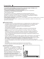 3
3
-
 4
4
-
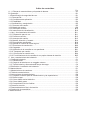 5
5
-
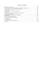 6
6
-
 7
7
-
 8
8
-
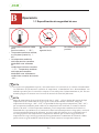 9
9
-
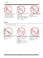 10
10
-
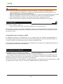 11
11
-
 12
12
-
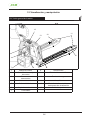 13
13
-
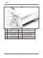 14
14
-
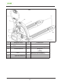 15
15
-
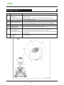 16
16
-
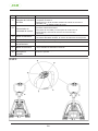 17
17
-
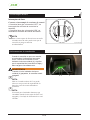 18
18
-
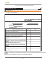 19
19
-
 20
20
-
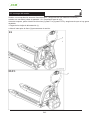 21
21
-
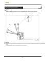 22
22
-
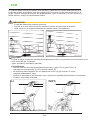 23
23
-
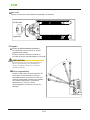 24
24
-
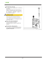 25
25
-
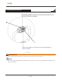 26
26
-
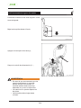 27
27
-
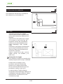 28
28
-
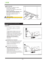 29
29
-
 30
30
-
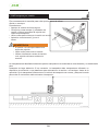 31
31
-
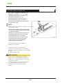 32
32
-
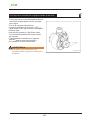 33
33
-
 34
34
-
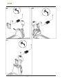 35
35
-
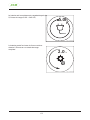 36
36
-
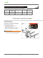 37
37
-
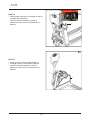 38
38
-
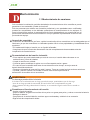 39
39
-
 40
40
-
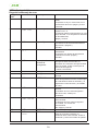 41
41
-
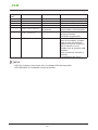 42
42
-
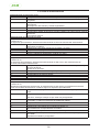 43
43
-
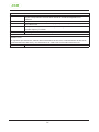 44
44
-
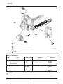 45
45
-
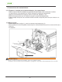 46
46
-
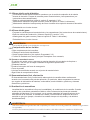 47
47
-
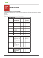 48
48
-
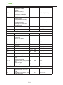 49
49
-
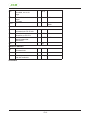 50
50
-
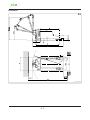 51
51
-
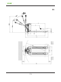 52
52
-
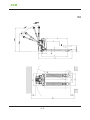 53
53
-
 54
54
-
 55
55
-
 56
56
-
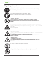 57
57
-
 58
58
-
 59
59
-
 60
60
-
 61
61
-
 62
62
-
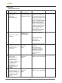 63
63
-
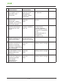 64
64
-
 65
65
-
 66
66
-
 67
67
-
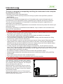 68
68
-
 69
69
-
 70
70
-
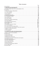 71
71
-
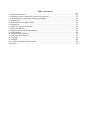 72
72
-
 73
73
-
 74
74
-
 75
75
-
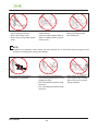 76
76
-
 77
77
-
 78
78
-
 79
79
-
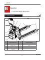 80
80
-
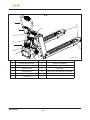 81
81
-
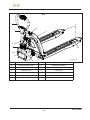 82
82
-
 83
83
-
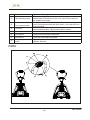 84
84
-
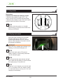 85
85
-
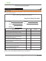 86
86
-
 87
87
-
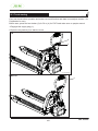 88
88
-
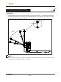 89
89
-
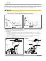 90
90
-
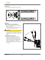 91
91
-
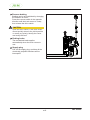 92
92
-
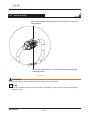 93
93
-
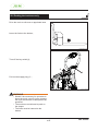 94
94
-
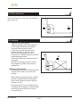 95
95
-
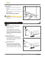 96
96
-
 97
97
-
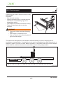 98
98
-
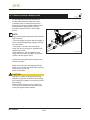 99
99
-
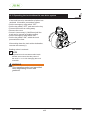 100
100
-
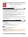 101
101
-
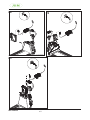 102
102
-
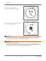 103
103
-
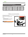 104
104
-
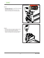 105
105
-
 106
106
-
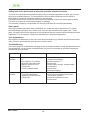 107
107
-
 108
108
-
 109
109
-
 110
110
-
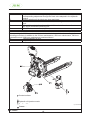 111
111
-
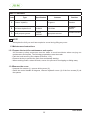 112
112
-
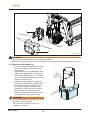 113
113
-
 114
114
-
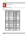 115
115
-
 116
116
-
 117
117
-
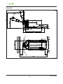 118
118
-
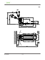 119
119
-
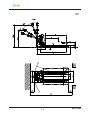 120
120
-
 121
121
-
 122
122
-
 123
123
-
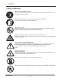 124
124
-
 125
125
-
 126
126
-
 127
127
-
 128
128
-
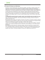 129
129
-
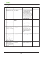 130
130
-
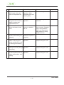 131
131
-
 132
132


