
INSTALLATION GUIDE
Model ERV70S
(side ports)
Model ERV70T
(top ports)
Models HRV80S*
and HRV90S*
(side ports)
Models HRV80T*
and HRV90T*
(top ports)
* These products earned the ENERGY STAR
®
by meeting strict energy efficiency guidelines set by Natural Resources
Canada and the US EPA. They meet ENERGY STAR requirements only when used in Canada.
RESIDENTIAL INDOOR USE ONLY
! !
READ AND SAVE THESE INSTRUCTIONS
22633 rev. 02
VB0192
VB0190
VB0193
VB0191
Broan-NuTone LLC; Hartford, Wisconsin www.broan.com 800-558-1711
REGISTER YOUR PRODUCT ONLINE AT: www.broan.com/register
For additional information - visit www.broan.com

Because of the amount of models covered in this publication, the illustrations are typical ones. Some details of your unit may be slightly
different than the ones shown.
Please take note that this manual uses the following symbols to emphasize particular information:
Identifies an instruction which, if not followed, might cause serious personal injuries including possibility of death.
Identifies an instruction which, if not followed, may severely damage the unit and/or its components.
NOTE: Indicates supplementary information needed to fully complete an instruction.
2
WARNING
!
CAUTION
ABOUT THIS GUIDE
ABOUT THESE UNITS
LIMITATION
For residential (domestic) installation only. Installation work and electrical wiring must be done by a qualified person(s) in accordance with
all applicable codes and standards, including fire-rated construction codes and standards.
WARNING
!
TO REDUCE THE RISK OF FIRE, ELECTRIC SHOCK, OR INJURY TO PERSON(S) OBSERVE THE FOLLOWING:
1. Use this unit only in the manner intended by the manufacturer. If you have questions, contact the manufacturer at the address or
telephone number listed in the warranty.
2. We recommend that your unit be inspected by a specialized technician once a year.
3. Before servicing or cleaning the unit, disconnect power cord from electrical outlet.
4. This unit is not designed to provide combustion and/or dilution air for fuel-burning appliances.
5. When cutting or drilling into wall or ceiling, do not damage electrical wiring and other hidden utilities.
6. Do not use the units with any solid-state speed control device other than the corresponding ones listed below:
7. This unit must be grounded. The power supply cord has a 3-prong grounding plug for your personal safety. It must be plugged into a
mating 3-prong grounding receptacle, grounded in accordance with the national electrical code and local codes and ordinances.
Do not remove the ground prong. Do not use an extension cord.
8. Do not install in a cooking area or connect directly to any appliances.
9. Do not use to exhaust hazardous or explosive materials and vapors.
10. When performing installation, servicing or cleaning the unit, it is recommended to wear safety glasses and gloves.
11. Due to the weight of the unit, two installers are recommended to perform installation.
12. When applicable local regulations comprise more restrictive installation and/or certification requirements, the aforementioned requirements
prevail on those of this document and the installer agrees to conform to these at his own expenses.
MAIN CONTROL AUXILIARY CONTROL
VT8W, VT7W, VT4W OR VT6W 59W, VB20W, VB60W
CAUTION
1. To avoid prematurate clogged filters, turn OFF the unit during construction or renovation.
2. Please read specification label on product for further information and requirements.
3. Be sure to duct air outdoors – Do not intake/exhaust air into spaces within walls or ceiling or into attics, crawl spaces, or garage.
4. Intended for residential installation only in accordance with the requirements of NFPA 90B.
5. Do not run any air ducts directly above or closer than 2 ft to any furnace or its supply plenum, boiler, or other heat producing appliance.
If a duct has to be connected to the furnace return plenum, it must be connected not closer than 9’ 10” from this plenum connection to
the furnace.
6. The ductwork is intended to be installed in compliance with all applicable codes.
7. When leaving the house for a long period of time (more than two weeks), a responsible person should regularly check if the unit
operates adequately.
8. If the ductwork passes through an unconditioned space (e.g.: attic), the unit must operate continuously except when performing
maintenance and/or repair. Also, the ambient temperature of the house should never drop below 65°F.

TABLE OF CONTENTS
1. T ECHNICAL SUPPORT . . . . . . . . . . . . . . . . . . . . . . . . . . . . . . . . . . . . . . . . . . . . . . 4
2. T
ECHNICAL DATA . . . . . . . . . . . . . . . . . . . . . . . . . . . . . . . . . . . . . . . . . . . . . . . 4-5
2.1 AIR DISTRIBUTION . . . . . . . . . . . . . . . . . . . . . . . . . . . . . . . . . . . . . . . . . . . . . . . . . . 4
2.2 D
EFROST CYCLES . . . . . . . . . . . . . . . . . . . . . . . . . . . . . . . . . . . . . . . . . . . . . . . . . . 4
3. TYPICAL INSTALLATIONS. . . . . . . . . . . . . . . . . . . . . . . . . . . . . . . . . . . . . . . . . . . . . . 5
3.1 FULLY DUCTED SYSTEM . . . . . . . . . . . . . . . . . . . . . . . . . . . . . . . . . . . . . . . . . . . . . . . 5
3.2 CENTRAL DRAW POINT . . . . . . . . . . . . . . . . . . . . . . . . . . . . . . . . . . . . . . . . . . . . . . . . 5
3.3 SIMPLIFIED INSTALLATION . . . . . . . . . . . . . . . . . . . . . . . . . . . . . . . . . . . . . . . . . . . . . . . 5
4. INSTALLATION . . . . . . . . . . . . . . . . . . . . . . . . . . . . . . . . . . . . . . . . . . . . . . . . 6-10
4.1 INSPECT THE CONTENT OF THE BOX . . . . . . . . . . . . . . . . . . . . . . . . . . . . . . . . . . . . . . . . . . 6
4.2 LOCATING THE UNIT . . . . . . . . . . . . . . . . . . . . . . . . . . . . . . . . . . . . . . . . . . . . . . . . . 6
4.3 PLANNING OF THE DUCTWORK . . . . . . . . . . . . . . . . . . . . . . . . . . . . . . . . . . . . . . . . . . . . . 6
4.4 INSTALLING THE DUCTWORK AND REGISTERS . . . . . . . . . . . . . . . . . . . . . . . . . . . . . . . . . . . . . 6-8
4.5 CONNECTING THE DUCTS TO THE UNIT . . . . . . . . . . . . . . . . . . . . . . . . . . . . . . . . . . . . . . . . . 9
4.6 INSTALLING TWO EXTERIOR HOODS . . . . . . . . . . . . . . . . . . . . . . . . . . . . . . . . . . . . . . . . . 10
4.7 CONNECTING THE DRAIN . . . . . . . . . . . . . . . . . . . . . . . . . . . . . . . . . . . . . . . . . . . . . . 10
5. CONTROLS . . . . . . . . . . . . . . . . . . . . . . . . . . . . . . . . . . . . . . . . . . . . . . . . . 11-14
5.1 UNITS BOOTING SEQUENCE . . . . . . . . . . . . . . . . . . . . . . . . . . . . . . . . . . . . . . . . . . . . . 11
5.2 INTEGRATED CONTROL . . . . . . . . . . . . . . . . . . . . . . . . . . . . . . . . . . . . . . . . . . . . . . . 11
5.3 SETTING EXTENDED DEFROST . . . . . . . . . . . . . . . . . . . . . . . . . . . . . . . . . . . . . . . . . . . . 11
5.4 ELECTRICAL CONNECTION TO MAIN CONTROL . . . . . . . . . . . . . . . . . . . . . . . . . . . . . . . . . . . . . 12
5.5 ELECTRICAL CONNECTION TO OPTIONAL AUXILIARY CONTROLS . . . . . . . . . . . . . . . . . . . . . . . . . . . . . 13
6. ELECTRICAL CONNECTION TO THE FURNACE . . . . . . . . . . . . . . . . . . . . . . . . . . . . . . . . . . . 13
7. W
IRING DIAGRAMS . . . . . . . . . . . . . . . . . . . . . . . . . . . . . . . . . . . . . . . . . . . . . 14-16
7.1 HRV80TE AND HRV80SE MODELS . . . . . . . . . . . . . . . . . . . . . . . . . . . . . . . . . . . . . . . . 14
7.2 ERV70T AND ERV70S MODELS . . . . . . . . . . . . . . . . . . . . . . . . . . . . . . . . . . . . . . . . . . 15
7.3 HRV90T AND HRV90S MODELS . . . . . . . . . . . . . . . . . . . . . . . . . . . . . . . . . . . . . . . . . . 16
8. BALANCING THE UNIT . . . . . . . . . . . . . . . . . . . . . . . . . . . . . . . . . . . . . . . . . . . . . 17
8.1 WHAT YOU NEED TO BALANCE THE UNIT . . . . . . . . . . . . . . . . . . . . . . . . . . . . . . . . . . . . . . . 17
8.2 PRELIMINARY STAGES TO BALANCE THE UNIT . . . . . . . . . . . . . . . . . . . . . . . . . . . . . . . . . . . . . 17
8.3 BALANCING PROCEDURE . . . . . . . . . . . . . . . . . . . . . . . . . . . . . . . . . . . . . . . . . . . . . . 17
9. SERVICE PARTS . . . . . . . . . . . . . . . . . . . . . . . . . . . . . . . . . . . . . . . . . . . . . . . . 18
10. T
ROUBLESHOOTING . . . . . . . . . . . . . . . . . . . . . . . . . . . . . . . . . . . . . . . . . . . . .19-20
3

1. TECHNICAL SUPPORT (FOR ASSISTANCE)
FOR ASSISTANCE, CALL ON WEEKDAYS, 8:30 AM TO 5:00 PM (EASTERN STANDARD TIME).
NOTE: THIS PHONE NUMBER IS STRICTLY RESERVED FOR INSTALLERS USE ONLY. DO NOT CALL THIS NUMBER TO ORDER PA RT S.
1-800-543-3055 (
TOLL FREE)
2. TECHNICAL DATA
2.1 AIR DISTRIBUTION
VF0051
TOP PORTS UNITS SIDE PORTS UNITS
UNIT FRONT
UNIT FRONT
FRESH AIR
TO
BUILDING
STALE AIR
FROM
BUILDING
STALE AIR
TO
OUTDOORS
FRESH AIR
FROM
OUTDOORS
FRESH AIR
TO
BUILDING
STALE AIR
FROM
BUILDING
STALE AIR
TO
OUTDOORS
FRESH AIR
FROM
OUTDOORS
4
2.2 DEFROST CYCLES
ERV70T AND ERV70S UNITS
OUTDOOR
TEMPERATURE
DEFROST CYCLES
(MINUTES)
EXTENDED DEFROST*
CYCLES (MINUTES)
°F DEFROSTING
OPERATION
BETWEEN EACH
DEFROST
CYCLE
DEFROSTING
OPERATION
BETWEEN EACH
DEFROST CYCLE
23722715
5 7 22 7 15
-17715712
* In a cold region (outdoor temperature -17°F and lower), it may be necessary to setup EXTENDED DEFROST. See Section 5.3.
HRV80S, HRV80T, HRV90S AND HRV90T UNITS
OUTDOOR
TEMPERATURE
DEFROST CYCLES
(MINUTES)
EXTENDED DEFROST*
CYCLES (MINUTES)
°F DEFROSTING
OPERATION
BETWEEN EACH
DEFROST
CYCLE
DEFROSTING
OPERATION
BETWEEN EACH
DEFROST CYCLE
23530620
5 5 20 6 15
-17715712

5
3. TYPICAL INSTALLATIONS
Use the following illustrations as guidelines to help you decide on how the unit will be installed.
All the units should be hung from the joists.
If required, bathroom fans and a range hood may be used to exhaust stale air. Also, for homes with more than one level, we recommend
one exhaust register at the highest level.
There are 3 installation methods: Fully ducted, Central Draw Point and Simplified Installation.
NOTE: An electrical outlet has to be available within 3 feet of the unit.
3.1 FULLY DUCTED SYSTEM (PRIMARILY FOR HOMES WITH RADIANT HOT WATER OR ELECTRIC BASEBOARD HEATING)
VH0081
Stale air coming from the registers located at the highest level of the
house is exhausted outdoors. Fresh air from outdoors is filtered and
supplied by the register located in the lowest liveable level.
Homes with more than one level require at least one exhaust register at
the highest level.
See figure at right.
3.2 CENTRAL DRAW POINT (CONNECTION TO A FORCED AIR SYSTEM)
VH0082
Stale air coming from the registers located at the highest level of the
house is exhausted outdoors. Fresh air from outdoors is filtered and
supplied to the return (plenum) or the supply duct of the forced air unit.
See figure at right.
For this type of installation, it is not essential that the forced air system
blower runs when the unit is in operation, but we recommend it.
NOTE: Home with multiple forced air systems should have one unit on
each system.
3.3 SIMPLIFIED INSTALLATION (CONNECTION TO A FORCED AIR SYSTEM)
VH0082
Stale air is exhausted outdoors. Fresh air from outdoors is filtered and
supplied to the return (plenum) or the supply duct of the forced air unit.
See figure at right.
To avoid cross-contamination and achieve the highest efficiencies, the
forced air system blower must always be ON.
NOTE: Home with multiple forced air systems should have one unit on
each system.

6
4. INSTALLATION
4.1 INSPECT THE CONTENT OF THE BOX
Inspect the exterior of the unit for shipping damage. Ensure that there is no damage to the door, ports, power cord, etc.
4.2 LOCATING THE UNIT
Choose an appropriate location for the unit.
• Within an area of the house where the ambient temperature is kept between
50°F and 104°F.
• Away from living areas (dining room, living room, bedroom), if possible.
• So as to provide easy access to the interior of the unit, for quarterly and annual
maintenance.
• Close to an exterior wall, so as to limit the length of the insulated flexible duct to
and from the unit.
• Away from hot chimneys and other fire hazards.
• Allow for a power source (standard 3-prong grounding outlet).
• Close to a drain (HRV units only). If no drain is close by, use a pail to collect run-off.
Hang the unit with the four chains and springs provided. See illustration at right.
VD0242
Make sure the unit is level.
CAUTION
4.3 PLANNING OF THE DUCTWORK
• Keep it simple. Plan for a minimum of bends and joints.
• Keep the length of insulated ducts to a minimum.
• Do not ventilate crawl spaces or cold rooms. Do not attempt to recover the exhaust air from a dryer or a range hood. This
would cause clogging of the filters and recovery module.
• If the house has two floors or more, be sure to plan for at least one exhaust register on the highest lived-in level.
4.4 INSTALLING THE DUCTWORK AND REGISTERS
Stale air exhaust ductwork
• Install the stale air exhaust registers where the contaminants are produced: kitchen, living room, etc. Position the registers as
far from the stairway as possible and in such a way that the air circulates in all the lived-in spaces in the house.
• If a register is installed in the kitchen, it must be located at least 4 feet from the range.
• Install the registers 6 to 12 inches from the ceiling on an interior wall OR install them in the ceiling.
4.4.1 F
ULLY DUCTED SYSTEM (AS ILLUSTRATED IN SECTION 3.1)
Never install a stale air exhaust register in a closed room where a combustion device operates, such as a
gas furnace, a gas water heater or a fireplace.
WARNING
!
Fresh air distribution ductwork
• Install the fresh air distribution registers in bedrooms, dining rooms, living room and basement.
• Keep in mind that the fresh air registers must be located as far as possible from the stale air registers.
• Install the registers either in the ceiling or high on the walls with air flow directed towards the ceiling. (The cooler air will then
cross the upper part of the room and mix with room air, before descending to occupant’s level.)
• If a register must be floor installed, direct the airflow up the wall.

7
4. INSTALLATION (CONT’D)
4.4 INSTALLING THE DUCTWORK AND REGISTERS (CONT’D)
4.4.2 C
ENTRAL DRAW POINT (AS ILLUSTRATED IN SECTION 3.2)
Stale air exhaust ductwork
Same as for Fully Ducted System, described on point 4.4.1
Fresh air distribution ductwork
There are 2 methods for connecting the unit to the furnace/air handler:
When performing duct connections, always use approved tools and materials. Respect all corresponding
laws and safety regulations. Please refer to your local building code.
WARNING
!
When performing duct connections to the furnace supply duct, this duct must be sized to support the
additional airflow produced by the unit. Also, the use of metal duct is highly recommended.
CAUTION
Method 1: Supply side connection
• Cut an opening into the furnace supply duct at least 18 inches from the
furnace/air handler.
• Connect this opening to the Fresh air distribution port of the unit (use metal
duct, see figure at right).
• Make sure the unit duct forms an elbow inside the furnace/air handler ductwork.
• If desired, interlock (synchronize) the furnace/air handler blower operation (see
Section 6 Electrical Connection to the Furnace).
VJ0075
MINIMUM 18”
M
ETAL DUCT
Method 2: Return side connection
• Cut an opening into the furnace return duct not less than 10 feet from the
furnace/air handler (A+B).
• Connect this opening to the Fresh air distribution port of the unit (see figure
at right).
NOTE: For Method 2, it is not essential that the furnace/air handler runs when the
unit is operation, but we recommend it. If desired, interlock (synchronize)
the furnace/air handler blower operation (see Section 6 Electrical
Connection to the Furnace).
VJ0076
B
A
A+B = NOT LESS
THAN 10’

4. INSTALLATION (CONT’D)
4.4 INSTALLING THE DUCTWORK AND REGISTERS (CONT’D)
4.4.3 S
IMPLIFIED INSTALLATION (AS ILLUSTRATED IN SECTION 3.3)
8
When performing duct connections, always use approved tools and materials. Respect all corresponding
laws and safety regulations. Please refer to your local building code.
WARNING
!
When performing duct connections to the furnace supply duct (Method 1), this duct must be sized to
support the additional airflow produced by the unit. Also, the use of metal duct is highly recommended.
For a Return-Return installation, the furnace blower must be in operation when the unit is in operation.
CAUTION
There are 2 methods for connecting the unit to the furnace/air handler:
Method 1: Supply-Return Connection Method 2: Return-Return Connection
VJ0077
A
B
MINIMUM 18”
M
ETAL DUCT
A+B = NOT LESS
THAN 10’
VJ0078
B
A
A+B = NOT LESS
THAN 10’
MINIMUM 3’
Stale air intake
• Cut an opening into the furnace return duct not less than 10 feet from the furnace/air handler (A+B).
• Connect this opening to the Exhaust air from building port of the unit.
Fresh air distribution
• Same instructions as for Method 1 or Method 2, Section 4.4.2.
For Method 2 (Return-Return), make sure there is a distance of at least 3 feet between the 2 connections to the furnace/air
handler.
If using Method 2, make sure the furnace/air handler blower operation is synchronized with the unit
operation! See Section 6 Electrical Connection to the Furnace.
CAUTION
NOTE: For Method 1, it is not essential to synchronize the furnace blower operation with the unit operation, but we recommend it.

Insulated flexible ducts
Use the following procedure to connect the insulated flexible ducts to the ports of the unit (Exhaust air to outdoors and Fresh air
from outdoors ports).
All units have those 2 ports equipped with integrated balancing damper. Prior to install the
insulated flexible ducts, ensure these both ports have their damper entirely open (their
adjusment pin (A) must be set vertical, as shown at right).
4. INSTALLATION (CONT’D)
4.5 CONNECTING THE DUCTS TO THE UNIT
9
VJ0033
A
Pull back the insulation to expose the flexible duct.
Attach the flexible duct to the port using tie wrap.
Pull the insulation over the joint and tuck in between the inner and outer rings of the double collar.
Pull down the vapor barrier (shaded part in illustrations below) over the outer ring to cover it completely. Fasten in place the vapor
barrier using the port strap included in unit parts bag). To do so, insert one collar pin through vapor barrier and first strap hole, then insert
the other collar pin through vapor barrier and center strap hole and close the loop by inserting the first collar pin in the last strap hole.
If ducts have to go through an unconditioned space (e.g.: attic), always use insulated ducts.
CAUTION
Make sure the vapor barrier on the insulated ducts does not tear during installation to avoid condensation
within the ducts.
CAUTION
VJ0074
1
2
3
4
COLLAR PIN
COLLAR PIN
Non-insulated rigid ducts
Use metal screws and duct tape
to connect the rigid ducts to the
unit ports.
Non-insulated flexible ducts
Use tie wraps to connect the flexible
ducts to the unit ports.
VJ0073
NOTE: All units ports were created to be connected to ducts having a minimum of 4” diameter, but if need be, they can be connected
to bigger sized ducts by using an appropriate transition (e.g.: 4” diameter to 5” diameter transition).

4. INSTALLATION (CONT’D)
4.6 INSTALLING TWO EXTERIOR HOODS
10
VD0028
EXHAUST HOOD
INTAKE HOOD
18”
18”
4” Ø
6’
6’
18”
O
PTIONAL
DUCT
LOCATION
TAPE AND DUCT TIE
Choose an appropriate location to install the exterior
hoods:
• There must be a minimum distance of 6 feet
between the hoods to avoid cross-contamination
• There must be a minimum distance of 18 inches from
the ground
Make sure the intake hood is at least 6 feet
away from any of the following:
• Dryer exhaust, high efficiency furnace vent,
central vacuum vent
• Gas meter exhaust, gas barbecue-grill
• Any exhaust from a combustion source
• Garbage bin and any other source of contamination
WARNING
!
Refer to figure at right for connecting insulated ducts to
the exterior hoods. An “Anti-gust intake hood’’ should be
installed in regions where a lot of snow is expected to fall.
4.7 CONNECTING THE DRAIN
A drain tubing (included) must be installed for all HRV units. For ERV units, it is not required, however, it is
recommended for climates where the outdoor temperature typically remains below -13°F, (over a 24-hour
period) for several days in a row, combined with an indoor humidity of 40% or higher.
CAUTION
VO0190
Connect the plastic tube to the inner drain fitting
located under the unit as shown.
NOTE: For ERV units, remove drain plug outside
the unit prior to install tubing.
VD0240A
± 1”
Make a water trap loop in the tube to prevent the
unit from drawing unpleasant odors from the drain
source. Run the tube to the floor drain or to an
alternative drain pipe or pail.
IMPORTANT
If using a pail to collect water, locate the tube end
approximately 1” from the top of the pail in order to
prevent water from being drawn back up into the unit.
TIE-WRAP

5. CONTROLS
11
All units are equipped with an integrated control located on upper left side of the unit. Plug the unit.
5.1 BOOTING SEQUENCE
The unit booting sequence is similar to a personnal computer boot sequence. Each time the unit is plugged after being unplugged, or
after a power failure, the unit will perform a 30-second booting sequence before starting to operate.
During the booting sequence, the integrated control LED will light GREEN for 5 seconds, and then will turn RED. During this RED light
phase, the unit is checking and resetting the motorized damper position. Once the motorized damper position completely set, the RED
light turns off and the booting sequence is done.
NOTE: No command will be taken until the unit is fully booted.
5.2 INTEGRATED CONTROL
VE0220
2
1
Use the push button (1) to control the unit. The LED (2) will then show on which mode the unit is in.
Refer to table below to see how to operate the unit using its integrated control.
LED COLOR RESULTS
AMBER UNIT IS ON LOW SPEED
GREEN UNIT IS ON HIGH SPEED
NO LIGHT UNIT IS OFF
If a problem occurs during the unit operation, its integrated control LED (2) will blink. The color of the blinking light depends on the
type of error detected. Refer to Section 10 Troubleshooting on page 19 for further details.
NOTE: WHEN USING MAIN CONTROL, THE INTEGRATED CONTROL MUST BE TURNED OFF.
5.3 SETTING EXTENDED DEFROST
These units are factory set to normal defrost. In cold region (outdoor temperature -17°F and lower), it may be necessary to setup
extended defrost. During the first 2 seconds of booting sequence, while the integrated control LED is GREEN, press on push button
for 3 seconds to set the unit in extended defrost; the LED will blink AMBER to show the unit is in extended defrost mode. After that,
the LED will shut off, then light RED (the unit returns in its booting sequence).

5. CONTROLS (CONT’D)
5.4 ELECTRICAL CONNECTION TO MAIN CONTROL
12
For more convenience, these units can also be controlled using an optional main wall control.
NOTES: 1. The integrated control must be turned OFF to use an optional main control.
2. If an optional auxiliary control is used, if activated, this auxiliary control will override the optional main control.
Always disconnect the unit before making any connections. Failure in disconnecting power could result in
electric shock or damage of the wall control or electronic module inside the unit.
WARNING
!
Never install more than one optional main wall control per unit. Make sure that the wires do not short-circuit
between themselves or by touching any other components on the wall control. Avoid poor wiring connections. To
reduce electrical interference (noise) potential, do not run wall control wiring next to control contactors or near
light dimming circuits, electrical motors, dwelling/building power or lighting wiring, or power distribution panel.
CAUTION
Use the terminal connector included in the installation kit to perform the electrical
connection for main and optional wall controls. Check if all wires are correctly inserted
in their corresponding holes in the terminal block. (A wire is correctly inserted when its
orange receptacle is lower than another one without wire. On picture at right, wire A is
correctly inserted, but wire B is not.)
VE0272
A
B
5.4.3 ELECTRICAL CONNECTION
TO VT4W MAIN WALL CONTROL
NO C NC I OC OL Y R G B
B G
G
B
Y
VE0328A
Y
VT4W
MAIN WALL CONTROL
REAR VIEW
5.4.2 ELECTRICAL CONNECTION
TO VT7W MAIN WALL CONTROL
NO C NC I OC OL Y R G B
VE0250
5.4.1 ELECTRICAL CONNECTION
TO VT8W MAIN WALL CONTROL
NO C NC I OC OL Y R G B
VE0181
SMART
SET
MODE
PREF
5.4.4 ELECTRICAL CONNECTION
TO VT6W MAIN WALL CONTROL
NO C NC I OC OL Y R G B
VE0187

5. CONTROLS (CONT’D)
13
VE0221
TERMINAL
CONNECTOR
Once the control(s) connections have been made, insert the terminal connector in the
electrical compartment interface.
6. ELECTRICAL CONNECTION TO THE FURNACE
Never connect a 120-volt AC circuit to the terminals of the furnace interlock (standard wiring). Only use the low
voltage class 2 circuit of the furnace blower control.
WARNING
!
For a furnace connected to a cooling system:
On some older thermostats, energizing the “R” and “G” terminals at the furnace has the effect of energizing “Y” at the thermostat and
thereby turning on the cooling system. If you identify this type of thermostat, you must use the ALTERNATE FURNACE INTERLOCK WIRING.
S
TANDARD FURNACE INTERLOCK WIRING ALTERNATE FURNACE INTERLOCK WIRING
W R G
Y
W
R
G
C
Y
UNIT TERMINAL CONNECTOR
THERMOSTAT
TERMINALS
FOUR
WIRES
TWO WIRES
heating only
FURNACE
24-VOLT
TERMINAL BLOCK
TWO WIRES
COOLING SYSTEM
NO C NC I OC OL Y R G B
W R G Y
W
R
Y
R
G
Y
C
THERMOSTAT
TERMINAL
4 WIRES
2 WIRES
heating only
wiring
nuts
FURNACE
24-VOLT
TERMINAL BLOCK
2 WIRES
COOLING SYSTEM
NO
NC
C
UNIT TERMINAL CONNECTOR
NO C NC I OC OL Y R G B
VE0108A
5.5 ELECTRICAL CONNECTION TO OPTIONAL AUXILIARY WALL CONTROLS
NO C NC I OC OL Y R G B
VE0371
59W
VB20W or VB60W

7. W IRING DIAGRAMS
14
WARNING
!
• Risk of electric shocks. Before performing any maintenance or servicing, always disconnect the unit from its power source.
• This product is equipped with an overload protection (fuse). A blown fuse indicates an overload or a short-circuit
situation. If the fuse blows, unplug the product and check the polarity and voltage output from the outlet. Replace
the fuse as per the servicing instructions (refer to wiring diagram for proper fuse rating) and verify the product. If
the replaced fuse blows, it may be a short-circuit and the product must be discarded or returned to an authorized
service center for examination and/or repair.
BK
W
G
A1
J6
1
2
J10
1
2
J14
10
9
8
7
6
5
4
3
2
1
12345
J12
J13
ICP
21345
J8
4321
J9
24 V Class 2
9.5 V
Class 2
C1
5 µF
2154321
12
J3
J2
J1
M2
A2
F1
T1
120 VAC
60 Hz
S1
OVERRIDE SWITCH
(OPTIONAL)
F
IELD WIRING
REMOTE
CONTROL
FURNACE BLOWER
INTERLOCK
(OPTIONAL)
D
AMPER ELECTRONIC
ASSEMBLY
ELECTRONIC ASSEMBLY
DAMPER MOTOR
3A
3AG T
YPE
COLOR CODE
t˚
VE0316A
M
J4-1
J9-3
J6-1
J6-2
J4-2
M
J2-1
J3-1
J3-2J2-2
J12-2
K4
K3
K2
T1
+-
~
~
L
INE
N
EUTRAL
120 VAC
A2
DAMPER MOTOR
M2
B
LOWER MOTOR
M1
C1
M
OTOR
C
APACITOR
F1
J12-1
J10-2
J10-1
J4-3
J9-1
24 VAC
9.5 VAC
J8-4
J8-5
J8-2
J8-1
LOGIC DIAGRAM
WIRING DIAGRAM
M1
BL
BR
J4
1
2
3
BK
B
G
R
R
G
BK
Y
Y
OL
OC
I
LINE VOLTAGE
CLASS 2 LOW VOLTAGE FACTORY WIRING
CLASS 2 LOW VOLTAGE FIELD WIRING
BLACK
BLUE
BROWN
GREEN
NO CONNECTION
BK
BL
BR
G
NC
ORANGE
PURPLE
RED
WHITE
YELLOW
O
P
R
W
Y
O
O
Y
Y
THERMISTOR
R1
BLOWER
MOTOR
MOTOR
CAPACITOR
nc
nc
BK
120 V
94 V
83 V
78 V
69 V
neutral
BL
P
BR
R
W
R
BR
P
R
BL BL
321
JU1
M H
123
JU1
H M
J9-2
94 VAC
83 VAC
78 VAC
69 VAC
nc
nc
Damper system
CPU
K2 K3 K4K1 K5
S1
J11-2 J11-1
7.1 HRV80T AND HRV80S MODELS

7. W IRING DIAGRAMS (CONT'D)
15
WARNING
!
• Risk of electric shocks. Before performing any maintenance or servicing, always disconnect the unit from its power source.
• This product is equipped with an overload protection (fuse). A blown fuse indicates an overload or a short-circuit
situation. If the fuse blows, unplug the product and check the polarity and voltage output from the outlet. Replace
the fuse as per the servicing instructions (refer to wiring diagram for proper fuse rating) and verify the product. If
the replaced fuse blows, it may be a short-circuit and the product must be discarded or returned to an authorized
service center for examination and/or repair.
BK
W
G
A1
J6
1
2
J10
1
2
J14
10
9
8
7
6
5
4
3
2
1
12345
J12
J13
ICP
21345
J8
4321
J9
24 V Class 2
9.5 V
Class 2
C1
5 µF
2154321
12
J3
J2
J1
M2
A2
C2
F1
T1
120 VAC
60 Hz
S1
OVERRIDE SWITCH
(OPTIONAL)
F
IELD WIRING
REMOTE
CONTROL
FURNACE BLOWER
INTERLOCK
(OPTIONAL)
T
HERMISTOR
DAMPER ELECTRONIC
ASSEMBLY
ELECTRONIC ASSEMBLY
DAMPER MOTOR
3A
3AG T
YPE
COLOR CODE
t˚
VE0335A
M
J4-1
J9-3
J6-1
J6-2
J4-2
M
J2-1
J3-1
J3-2J2-2
J12-2
K4
K3
K2
T1
+-
~
~
LINE
NEUTRAL
120 VAC
A2
D
AMPER
M
OTOR
B
LOWER
M
OTOR
C1
MOTOR CAPACITOR
CPU
K2 K3 K4
3A
J12-1
J10-2
J10-1
J4-3
J9-1
24 VAC
9.5 VAC
C2
MOTOR SPEED
J8-4
J8-5
J8-2
J8-1
LOGIC DIAGRAM
WIRING DIAGRAM
M1
BL
BR
J4
1
2
3
BK
B
G
R
R
G
BK
Y
Y
OL
OC
I
LINE VOLTAGE
CLASS 2 LOW VOLTAGE FACTORY WIRING
CLASS 2 LOW VOLTAGE FIELD WIRING
13 µF
BLACK
BLUE
BROWN
GREEN
BK
BL
BR
G
O
RANGE
RED
WHITE
YELLOW
O
R
W
Y
O
O
Y
Y
R1
BLOWER
MOTOR
MOTOR
CAPACITOR
K1 K5
S1
J11-2 J11-1
BK
R
W
7.2 ERV70T AND ERV70S MODELS

7. W IRING DIAGRAMS (CONT'D)
16
WARNING
!
• Risk of electric shocks. Before performing any maintenance or servicing, always disconnect the unit from its power source.
• This product is equipped with an overload protection (fuse). A blown fuse indicates an overload or a short-circuit
situation. If the fuse blows, unplug the product and check the polarity and voltage output from the outlet. Replace
the fuse as per the servicing instructions (refer to wiring diagram for proper fuse rating) and verify the product. If
the replaced fuse blows, it may be a short-circuit and the product must be discarded or returned to an authorized
service center for examination and/or repair.
BK
W
G
A1
J6
1
2
J10
1
2
J14
10
9
8
7
6
5
4
3
2
1
12345
J12
J13
ICP
21345
J8
4321
J9
24 V Class 2
9.5 V
Class 2
C1
6 µF
2154321
12
J3
J2
J1
M2
A2
F1
T1
120 VAC
60 Hz
S1
OVERRIDE SWITCH
(OPTIONAL)
F
IELD WIRING
REMOTE
CONTROL
FURNACE BLOWER
INTERLOCK
(OPTIONAL)
D
AMPER ELECTRONIC
ASSEMBLY
ELECTRONIC ASSEMBLY
DAMPER MOTOR
3A
3AG T
YPE
COLOR CODE
t˚
VE0317A
M
J4-1
J9-3
J6-1
J6-2
J4-2
M
J2-1
J3-1
J3-2J2-2
J12-2
K4
K3
K2
T1
+-
~
~
L
INE
N
EUTRAL
120 VAC
A2
DAMPER MOTOR
M2
B
LOWER MOTOR
M1
C1
M
OTOR
C
APACITOR
F1
J12-1
J10-2
J10-1
J4-3
J9-1
24 VAC
9.5 VAC
J8-4
J8-5
J8-2
J8-1
LOGIC DIAGRAM
WIRING DIAGRAM
M1
BL
BR
J4
1
2
3
BK
B
G
R
R
G
BK
Y
Y
OL
OC
I
LINE VOLTAGE
CLASS 2 LOW VOLTAGE FACTORY WIRING
CLASS 2 LOW VOLTAGE FIELD WIRING
BLACK
BLUE
BROWN
GREEN
NO
CONNECTION
BK
BL
BR
G
NC
ORANGE
PURPLE
RED
WHITE
YELLOW
O
P
R
W
Y
O
O
Y
Y
THERMISTOR
R1
BLOWER
MOTOR
MOTOR
CAPACITOR
nc
nc
BK
120 V
94 V
83 V
78 V
69 V
neutral
BL
P
BR
R
W
R
BR
P
R
BL BL
321
JU1
M H
123
JU1
H M
J9-2
94 VAC
83 VAC
78 VAC
69 VAC
nc nc
Damper system
CPU
K2 K3 K4K1 K5
S1
J11-2 J11-1
Ref.
1
Ref.
1
64 CFM optional low speed
selection can be achieved by
connecting BROWN to RED
(See Ref. 1)
7.3 HRV90T AND HRV90S MODELS

8. BALANCING THE UNIT
8.1 WHAT YOU NEED TO BALANCE THE UNIT
17
• A magnehelic gauge capable of measuring 0 to 0.5 inch of water (0 to 125 Pa) and
2 plastic tubes.
• The balancing chart of the unit, located on the unit door.
VP0009
8.2 PRELIMINARY STAGES TO BALANCE THE UNIT
• Seal all the unit ductwork with tape. Close all windows and doors.
• Turn off all exhaust devices such as range hood, dryer and bathroom fans.
• Make sure the balancing dampers are fully open (their adjusment pin (A) must be set
vertical, see illustration at right).
• Make sure all filters are clean (if it is not the first time the unit is balanced).
8.3 BALANCING PROCEDURE
1. Set the unit to high speed.
NOTE: Make sure that the furnace/air handler blower is ON if the installation is in any way connected to the ductwork of the
cold air return. If not, leave furnace/air handler blower OFF. If the outdoor temperature is below 32°F, make sure the unit
is not running in defrost while balancing. (By waiting 10 minutes after plugging the unit in, you are assured that the unit
is not in a defrost cycle.)
2. Place the magnehelic gauge on a level surface and adjust it to zero.
3. Connect tubing from gauge to EXHAUST air flow pressure taps (see diagram on unit
door).
Be sure to connect the tubes to their appropriate high/low fittings. If the gauge drops
below zero, reverse the tubing connections.
4. Note the CFM value from balancing chart on unit.
5. Repeat steps 3 and 4, but to FRESH air flow pressure taps.
6. Match highest CFM value to lowest by adjusting the balancing damper corresponding
to the highest value. To do so, rotate the adjusment pin.
See example below:
PRESSURE FRESH EXHAUST
IN
. W.G. CFM CFM
0.16 47 42
0.18 54 48
0.2 60 55
0.22 66 61
0.24 72 68
0.26 78 74
0.28 84 81
0.3 90 88
EXHAUST
READING
VALUES
FRESH
READING
VALUES
VJ0033
A
VJ0031
In that case, there is 78 CFM in FRESH air and 61 CFM in EXHAUST air. Then, using the adjusment pin, adjust (close) the
FRESH air balancing damper until the FRESH air flow matchs the EXHAUST air flow: 60 CFM (0.2 in. w.g.) with magnehelic
gauge connected to FRESH air flow pressure taps).
7. Secure both dampers in place with a fastening screw (included in the hardware kit).
8. Write the required air flow information on a label and stick it near the unit for future
reference (date, maximum speed air flows, your name, phone number and business
address).
NOTES: 1. Use conversion chart provided with the unit to convert magnehelic gauge
readings to equivalent cfm values.
2. The unit is considered balanced even if there is a difference of ±10 cfm
(or ± 5 l/s or 17 m³/h) between the two air flows.
S
CREW
VJ0031
VP0019
FRESH AIR
FLOW
EXHAUST AIR FLOW

9. SERVICE PARTS
18
VL0043
1
2
3
4
5
6
7
8
9
10
11
12
13
* PART NOT SHOWN.
REPLACEMENT PARTS AND REPAIR:
In order to ensure your ventilation unit remains in good working condition,
you must use Broan-NuTone LLC genuine replacement parts only. The
Broan-NuTone LLC replacement parts are specially designed for each
unit and are manufactured to comply with all the applicable certification
standards and maintain a high standard of safety. Any third party
replacement part used may cause serious damage and drastically reduce
the performance level of your unit, which will result in premature failing.
Broan-NuTone LLC recommends to contact a certified service depot for all
replacement parts and repair.
ITEM PART NO.DESCRIPTION HRV80T HRV80S ERV70T ERV70S HRV90T HRV90S
1 SV18854 4” ROUND METAL PORT 222222
2
SV19206 ELECTRONIC BOARD (HRV) 1 1 1 1
SV19207 ELECTRONIC BOARD (ERV) 1 1
3
SV16042 C
APACITOR 5 F 1111
SV61550 C
APACITOR 6 F 11
4
SV17244
TRANSFORMER
11
SV62480 1 1 1 1
5 SV19211 CAPACITOR 13 F 111111
6 SV19208 FILTER RETAINING WIRES (PAIR) 111111
7 SV18883 C
ORE FILTERS (PAIR) 111111
8 SV21527 D
OOR ASSEMBLY 111111
9
SV19199 H
EAT RECOVERY CORE 11 11
SV19200 E
NERGY RECOVERY CORE 11
10
SV18867 B
LOWER ASSEMBLY 1111
SV62176 B
LOWER ASSEMBLY 11
11
SV18868 V
ERTICAL PORTS DAMPER SYSTEM 111
SV18881 HORIZ. PORTS DAMPER SYSTEM* 111
12 SV19212 4” PORTS STRAPS 222222
13 SV18855 4” DOUBLE COLLAR PORT WITH DAMPER 222222
14 SV19213 H
ARDWARE KIT* 111111
15 SV16416 PCB CONNECTOR* 111111

10. TROUBLESHOOTING
19
Problems Possible causes You should try this
1 The error code E1 is
displayed on VT8W or
VT7W wall control screen.
• The wires may be in reverse position.
• The wires may be broken.
• The wires may have a bad connection.
• Ensure that the color wires have been connected to
their appropriate places.
• Inspect every wire and replace any that are damaged.
• Ensure the wires are correctly connected.
2 There is no outdoor
temperature displayed on
VT8W wall control screen
__
.
• The unit thermistor is defective (the
integrated control LED of the unit must
flash GREEN).
NOTE: At its very start-up or after a power failure, it takes
some minutes before the outdoor temperature
appears on screen. The shortest delay is
obtained when the wall control is set on MIN or
MAX in VENT Mode.
• Replace the unit damper system.
3 The VT8W or VT7W wall
control screen alternates
between normal display
and E3.
• The VT8W or VT7W wall control
may be defective.
• Replace the VT8W or VT7W wall control.
4 On VT8W wall control, there
is an important difference
between temperature
displayed and
real temperature.
• The unit thermistor is defective.
• The unit damper has been blocked or
broken.
• Replace the unit thermistor.
• Check for the proper operation of the unit damper;
replace if necessary.
5 Unit does not work. • The circuit board may be defective.
• The fuse may be defective.
6 The wall control does not
work.
• Unit integrated control set to low or high
speed (AMBER or GREEN
continuous LED).
• Unit not compatible with control.
• The wires may be in reverse position.
• The wires may be misconnected.
• The wires may be broken.
• Defective wall control.
• Press on the integrated push button until the LED
turns off.
• Check table on page 2 for control compatibility.
• Ensure that the color coded wires have been
connected to their appropriate places.
• Ensure the wires are correctly connected.
• Inspect every wire and replace any that are damaged.
• Replace the wall control.
If the unit does not work properly, reset the unit by unplugging it for one minute and then replug it. If it still not working properly,
refer to table below.
If the integrated control LED of the unit is flashing, this means the unit sensors detected a problem. See the table below to know where
the problem occurs on the unit.
LED Signal Error Type Action Unit Status
LED flashes GREEN Thermistor error Replace damper system. Unit works but will defrost frequently
LED flashes AMBER Damper error Go to point 6 Unit does not work
NO C NC I OC OL Y R G B
VE0097
• Unplug the unit. Disconnect
the main control and the
optional(s) control(s) (if
need be). Jump G and B
terminals. Plug the unit back and wait about 10 seconds.
If the motors run on high speed and the damper
opens, the circuit board is not defective.
• Check if fuse F1 (located on PCB) is blown. In that case,
replace fuse F1 as per wiring diagram specifications.

10. TROUBLESHOOTING (CONT’D)
20
Problems Possible causes You should try this
7 The damper system
does not work
(AMBER error code).
At power up, no RED LED. • See point 5.
At power up, LED lights RED and
there is a clicking sound coming from
electrical compartment, but damper
does not move:
• Ice or other things hindering the
damper movement.
• J12 unconnected or bad contact.
• Wrong connection of J8.
• The transformer may be defective
(no 24 VAC between J8-1 and J8-2).
• The damper actuator may be defective.
• Remove ice or hindering elements.
• Check J12 connection (both harness side and board
side).
• Check J8 connection.
• With unit powered and J9 connected, check if there
is about 20-24 VAC between transformer connector
J8-1 and J8-2 (ORANGE wires). If no, change the
transformer.
• Replace the damper system.
Damper moves but does not stop when
supposed to:
• Damper motor turns on reverse side.
• Bad connection of J12 connector.
• Damper PCB defective or damper motor
stripped gear.
• The main PCB is defective.
• Facing the damper motor shaft, the motor should
turn counterclockwise. If not, replace the damper
system.
• Check J12 connection (both harness side and
board side).
• Replace the damper system.
• Replace the main PCB.
8 Optional auxiliary control
does not work OR
its indicator light
does not stay on.
• The wires may be in reverse position.
• The wires may be misconnected.
• The wires may be broken.
• The auxiliary control may be defective.
• Ensure that the color coded wires have been
connected to their appropriate places.
• Ensure the wires are correctly connected.
• Inspect every wire and replace any that is damaged.
If wires are hidden into walls, test the control using a
shorter wire.
9 The blower motor does not
work.
• The fuse may be defective.
• The motor or capacitor may be defective.
NOTE: The unit must be unplugged to
perform this test.
• Check if fuse F1 (located on PCB) is blown. In that case,
replace fuse F1 as per wiring diagram specifications.
• Using a multimeter, check the ohms value on motor
connector. For BLUE and BLACK motor wires, the right
value is ± 68 ohms. For BLUE and BROWN motor
wires, the right value is ± 58 ohms. For BROWN and
BLACK motor wires, the right value is ± 126 ohms. If
the ohms values are the same, the motor is not defective.
Replace the motor capacitor.
10 The integrated control push
button does not work.
• The 30-second boot sequence is not
completed.
• See Section 5.1 Booting Sequence.
• Jump the OL and OC
terminals. If the unit
switch to high speed,
remove the push button
and test it right beside the unit using another shorter
wire. If it works here, change the wire. If it doesn’t,
change the auxiliary control.
NO C NC I OC OL Y R G B
VE0098

MANUAL DE INSTALACIÓN
VB0192
VB0190
Modelo ERV70S
(aberturas laterales)
Modelo ERV70T
(aberturas en la parte superior)
VB0193
VB0191
Modelos HRV80S*
y HRV90S*
(aberturas laterales)
Modelos HRV80T*
y HRV90T*
(aberturas en la parte superior)
* Estos productos han sido distinguidos con el logotipo ENERGY STAR
®
al cumplir las directrices de eficiencia energética
establecidas por el Ministerio de Recursos Naturales de Canadá y la Agencia Federal de Protección Ambiental (EPA) de
Estados Unidos. Los productos cumplen las exigencias del programa ENERGY STAR únicamente cuando se emplean
en Canadá.
SÓLO PARA USO RESIDENCIAL INTERIOR
! !
LEA Y CONSERVE ESTAS INSTRUCCIONES
22633 rev. 02
Broan-NuTone LLC; Hartford, Wisconsin www.broan.com 800-558-1711
REGISTRE SU PRODUCTO EN LÍNEA EN: www.broan.com/register
Para obtener más información, visitar nuestro sitio www.broan.com

Dado el gran número de modelos de los que trata este manual, las ilustraciones son de carácter general. Algunos detalles de su aparato
pueden ser ligeramente distinos de los que se muestran aquí.
Con el fin de hacer hincapié en determinada información, en este manual se emplean los siguientes símbolos:
Se refiere a una instrucción que, de no seguirse, podría causar daños corporales e incluso la muerte.
Se refiere a una instrucción que, de no seguirse, podría dañar gravemente el aparato o sus componentes.
NOTA: indica una información complementaria que es necesaria para completar totalmente una instrucción.
2
ADVERTENCIA
!
PRECAUCIÓN
OBSERVACIONES SOBRE ESTE MANUAL
OBSERVACIONES SOBRE ESTOS APARATOS
LÍMITES
Sólo para instalaciones residenciales. El trabajo de instalación y el cableado eléctrico han de ser efectuados por personal cualificado
conforme a todos los códigos y normas aplicables, incluso los relativos a lugares con alto riesgo de incendio.
ADVERTENCIA
!
PARA REDUCIR EL RIESGO DE INCENDIO, CHOQUE ELÉCTRICO O HERIDAS CORPORALES, SIGA LAS INDICACIONES
SIGUIENTES:
1. Utilice el aparato únicamente de la manera prevista por el fabricante. Si tiene preguntas, póngase en contacto con el fabricante en la
dirección o en el teléfono que aparecen en la garantía.
2. Le aconsejamos que un técnico especializado examine el aparato una vez al año.
3. Antes de realizar tareas de mantenimiento o de limpiar el aparato desenchufe el cable de alimentación de la toma eléctrica.
4. Este aparato no ha sido pensado para la combustión ni para el aire de dilución de aparatos que queman combustible.
5. Al cortar o taladrar en la pared o en el techo, procure no dañar el cableado eléctrico ni otras instalaciones ocultas.
6. No use el aparato con un dispositivo de control de velocidad de semiconductores diferente de los que aparecen en el cuadro siguiente:
7. El aparato debe conectarse a tierra. El cable de alimentación lleva un enchufe con toma de tierra de 3 patillas para su seguridad
personal. Debe enchufarse en una toma de corriente para tres patillas, conectada a tierra de acuerdo con el código eléctrico nacional
y los códigos y ordenanzas locales. No retire la patilla de la toma de tierra. No utilice el aparato con un cable prolongador.
8. No instale el aparato en un espacio donde se cocina ni lo conecte directamente a otro aparato.
9. No lo use para evacuar materias ni vapores peligrosos o explosivos.
10. Para la instalación, el mantenimiento o la limpieza del aparato se aconseja llevar lentes y guantes de seguridad.
11. Dado el peso del aparato, se aconseja dos personas para la instalación.
12. Cuando la reglamentación local aplicable sea más restrictiva en materia de instalación o certificación, dicha reglamentación prevalecerá
sobre las exigencias de este manual y el instalador acepta atenerse a dicha reglamentación y asumir los gastos correspondientes.
CONTROL PRINCIPAL CONTROL AUXILIAR
VT8W, VT7W, VT4W O VT6W 59W, VB20W, VB60W
PRECAUCIÓN
1. Para evitar que los filtros se obstruyan prematuramente, apague el aparato durante las obras de construcción o renovación.
2. Para mayor información sobre otras exigencias, lea la etiqueta de especificaciones que viene en el aparato.
3. Conecte los tubos de aire con el exterior. No tome ni evacue el aire en espacios situados entre paredes, en el techo o en un desván,
en sótanos pequeños ni en cocheras.
4. Aparato para instalación residencial únicamente, de acuerdo con las exigencias de la norma 90B de la NFPA.
5. No instale ningún tubo de aire directamente encima o a menos de 2 pies de un horno, de su cámara impelente, de una caldera o de
otro aparato que genere calor. Si hay que conectar un tubo a la cámara de retorno de una caldera, debe situarse al menos a 9’ y 10”
de la conexión de la cámara con la caldera.
6. Los tubos deben instalarse de acuerdo con todos los códigos aplicables.
7. Al ausentarse de la vivienda durante un periodo largo (más de dos semanas), una persona responsable debería verificar regularmente
si el aparato funciona correctamente.
8. Si los tubos pasan a través de un espacio no acondicionado (como un desván), el aparato debe funcionar constantemente, excepto
cuando haya que hacer tareas de mantenimiento o reparaciones. Asimismo, la temperatura ambiente de la casa nunca debería bajar
de 65 °F.

ÍNDICE
1. A POYO TÉCNICO . . . . . . . . . . . . . . . . . . . . . . . . . . . . . . . . . . . . . . . . . . . . . . . . . 4
2. D
ATOS TÉCNICOS . . . . . . . . . . . . . . . . . . . . . . . . . . . . . . . . . . . . . . . . . . . . . . . 4-5
2.1 DISTRIBUCIÓN DEL AIRE . . . . . . . . . . . . . . . . . . . . . . . . . . . . . . . . . . . . . . . . . . . . . . . . 4
2.2 C
ICLOS DE DESCONGELACIÓN . . . . . . . . . . . . . . . . . . . . . . . . . . . . . . . . . . . . . . . . . . . . . 4
3. INSTALACIÓN HABITUALES . . . . . . . . . . . . . . . . . . . . . . . . . . . . . . . . . . . . . . . . . . . . . 5
3.1 SISTEMA TOTALMENTE EQUIPADO CON TUBOS . . . . . . . . . . . . . . . . . . . . . . . . . . . . . . . . . . . . . . 5
3.2 VENTILACIÓN EN EL PUNTO DE ORIGEN . . . . . . . . . . . . . . . . . . . . . . . . . . . . . . . . . . . . . . . . . 5
3.3 INSTALACIÓN SIMPLIFICADA. . . . . . . . . . . . . . . . . . . . . . . . . . . . . . . . . . . . . . . . . . . . . . . 5
4. INSTALACIÓN . . . . . . . . . . . . . . . . . . . . . . . . . . . . . . . . . . . . . . . . . . . . . . . . 6-10
4.1 INSPECCIÓN DEL CONTENIDO DE LA CAJA . . . . . . . . . . . . . . . . . . . . . . . . . . . . . . . . . . . . . . . . 6
4.2 UBICACIÓN DEL APARATO . . . . . . . . . . . . . . . . . . . . . . . . . . . . . . . . . . . . . . . . . . . . . . . 6
4.3 PLANIFICACIÓN DE LAS TUBERÍAS . . . . . . . . . . . . . . . . . . . . . . . . . . . . . . . . . . . . . . . . . . . . 6
4.4 INSTALACIÓN DE LOS TUBOS Y REGISTROS . . . . . . . . . . . . . . . . . . . . . . . . . . . . . . . . . . . . . . . 6-8
4.5 CONEXIÓN DE LOS TUBOS AL APARATO . . . . . . . . . . . . . . . . . . . . . . . . . . . . . . . . . . . . . . . . . 9
4.6 INSTALACIÓN DE 2 BOCAS EXTERIORES . . . . . . . . . . . . . . . . . . . . . . . . . . . . . . . . . . . . . . . . 10
4.7 CONEXIÓN DEL DESAGÜE . . . . . . . . . . . . . . . . . . . . . . . . . . . . . . . . . . . . . . . . . . . . . . 10
5. CONTROLES. . . . . . . . . . . . . . . . . . . . . . . . . . . . . . . . . . . . . . . . . . . . . . . . . 11-14
5.1 SECUENCIA DE PUESTA EN MARCHA. . . . . . . . . . . . . . . . . . . . . . . . . . . . . . . . . . . . . . . . . . 11
5.2 CONTROL INTEGRADO. . . . . . . . . . . . . . . . . . . . . . . . . . . . . . . . . . . . . . . . . . . . . . . . 11
5.3 CONFIGURACIÓN DE LA DESCONGELACIÓN AMPLIADA . . . . . . . . . . . . . . . . . . . . . . . . . . . . . . . . . . 11
5.4 CONEXIÓN ELÉCTRICA CON EL CONTROLE DE PARED PRINCIPAL OPCIONAL . . . . . . . . . . . . . . . . . . . . . . . . . 12
5.5 CONEXIÓN ELÉCTRICA CON LOS CONTROLES AUXILIARES OPCIONALES . . . . . . . . . . . . . . . . . . . . . . . . . . . 13
6. CONEXIÓN ELÉCTRICA CON LA CALDERA . . . . . . . . . . . . . . . . . . . . . . . . . . . . . . . . . . . . . 13
7. D
IAGRAMAS DE CABLEADOS . . . . . . . . . . . . . . . . . . . . . . . . . . . . . . . . . . . . . . . . . . 14-16
7.1 MODELOS HRV80TE Y HRV80SE . . . . . . . . . . . . . . . . . . . . . . . . . . . . . . . . . . . . . . . . . 15
7.2 MODELOS ERV70T Y ERV70S . . . . . . . . . . . . . . . . . . . . . . . . . . . . . . . . . . . . . . . . . . 16
7.2 MODELOS HRV90T Y HRV90S . . . . . . . . . . . . . . . . . . . . . . . . . . . . . . . . . . . . . . . . . . 16
8. EQUILIBRADO DEL APARATO . . . . . . . . . . . . . . . . . . . . . . . . . . . . . . . . . . . . . . . . . . . 17
8.1 ELEMENTOS NECESARIOS PARA EQUILIBRAR EL APARATO . . . . . . . . . . . . . . . . . . . . . . . . . . . . . . . . . 17
8.2 ETAPAS PRELIMINARES PARA EQUILIBRAR EL APARATO . . . . . . . . . . . . . . . . . . . . . . . . . . . . . . . . . . 17
8.3 PROCEDIMIENTO DE EQUILIBRADO . . . . . . . . . . . . . . . . . . . . . . . . . . . . . . . . . . . . . . . . . . 17
9. PIEZAS DE RECAMBIO. . . . . . . . . . . . . . . . . . . . . . . . . . . . . . . . . . . . . . . . . . . . . . 18
10. S
OLUCIÓN DE PROBLEMAS . . . . . . . . . . . . . . . . . . . . . . . . . . . . . . . . . . . . . . . . . .19-20
3

1. PARA SOLICITAR APOYO TÉCNICO
PARA SOLICITAR APOYO, LLAME ENTRE SEMANA, DE 8.30 A 17.00 H. (HORA NORMAL DEL ESTE).
NOTA: ESTE TELÉFONO ESTÁ RESERVADO ESTRICTA Y ÚNICAMENTE A LOS INSTALADORES.
1-800-543-3055 (S
IN GASTOS)
2. DATOS TÉCNICOS
2.1 DISTRIBUCIÓN DEL AIRE
VF0051
ABERTURAS EN LA PARTE SUPERIOR ABERTURAS LATERALES
PARTE DELANTERA
PARTE DELANTERA
AIRE FRESCO
HACIA EL
INTERIOR
AIRE DE
SALIDA DESDE
EL INTERIOR
AIRE DE SALIDA
HACIA EL
EXTERIOR
AIRE FRESCO
DESDE EL
EXTERIOR
AIRE FRESCO
HACIA EL
INTERIOR
AIRE DE SALIDA
DESDE EL
INTERIOR
AIRE DE
SALIDA HACIA
EL EXTERIOR
AIRE FRESCO
DESDE EL
EXTERIOR
4
2.2 CICLOS DE DESCONGELACIÓN
* En las regiones frías (con temperaturas exteriores de -17 °F [-27 °C] y menos), puede ser necesario configurar la DESCONGELACIÓN
AMPLIADA. Véase la sección 5.3.
APARATOS ERV70T Y ERV70S
T
EMPERATURA
EXTERIOR
CICLOS DE DESCONGELACIÓN
(MINUTOS)
CICLOS DE DESCONGELACIÓN
AMPLIADOS* (MINUTOS)
°F DESCONGELACIÓN
TEMPO DE
FUNCIONAMIENTO
ENTRE CADA CICLO DE
DESCONGELACIÓN
DESCONGELACIÓN
TEMPO DE
FUNCIONAMIENTO
ENTRE CADA CICLO DE
DESCONGELACIÓN
23722715
5 7 22 7 15
-17715712
APARATOS HRV80S, HRV80T, HRV90S Y HRV90T
T
EMPERATURA
EXTERIOR
CICLOS DE DESCONGELACIÓN
(MINUTOS)
CICLOS DE DESCONGELACIÓN
AMPLIADOS* (MINUTOS)
°F DESCONGELACIÓN
TEMPO DE
FUNCIONAMIENTO
ENTRE CADA CICLO DE
DESCONGELACIÓN
DEFROSTING
TEMPO DE
FUNCIONAMIENTO
ENTRE CADA CICLO DE
DESCONGELACIÓN
235 30620
5 5 20 6 15
-177 15712

5
3. INSTALACIONES HABITUALES
Utilice las ilustraciones siguientes como referencia para elegir la forma de instalar el aparato.
Todos los aparatos deberían colgarse de vigas.
De ser necesario, se pueden utilizar ventiladores para cuarto de baño o una campana de cocina para sacar el aire viciado. Asimismo, en
las viviendas de más de un nivel aconsejamos un registro de salida en el nivel superior.
Hay 3 métodos de instalación: sistema totalmente equipado con tubos, ventilación en el punto de origen e instalación simplificada.
NOTA: ha de haber una toma eléctrica disponible a menos de 3 pies del aparato.
3.1 SISTEMA TOTALMENTE EQUIPADO CON TUBOS (PRICIPALMENTE PARA VIVIENDAS CON CALEFACCIÓN POR AGUA CALIENTE RADIANTE O POR
RADIATORES ELÉCTRICOS)
VH0081
El aire viciado proveniente del registro situado en el nivel superior de
la vivienda se extrae al exterior. El aire fresco del exterior se filtra y se
introduce por el registro situado en el nivel habitable inferior.
Las viviendas con más de un nivel necesitan al menos un registro de
salida en el nivel superior.
Véase la ilustración de la derecha.
3.2 VENTILACIÓN EN EL PUNTO DE ORIGEN (CONEXIÓN CON UN SISTEMA DE AIRE FORZADO)
VH0082
El aire viciado proveniente del registro situado en el nivel superior de
la vivienda se extrae al exterior. El aire fresco del exterior se filtra y se
introduce por el conducto de retorno (cámara) o de alimentación del
aparato de aire forzado.
Véase la ilustración de la derecha.
Para este tipo de instalación no es esencial que el ventilador impelente
del sistema de aire forzado funcione cuando el aparato esté funcionando,
pero es aconsejable.
NOTA: las viviendas con varios sistemas de aire forzado deberían
contar con un aparato para cada sistema.
3.3 INSTALACIÓN SIMPLIFICADA (CONEXIÓN CON UN SISTEMA DE AIRE FORZADO)
VH0082
El aire viciado se extrae al exterior. El aire fresco del exterior se filtra y
se introduce por el conducto de retorno (cámara) o de alimentación del
aparato de aire forzado.
Véase la ilustración de la derecha.
Para evitar la contaminación cruzada y lograr la máxima eficacia, el
ventilador impelente del sistema de aire forzado debe estar encendido
siempre.
NOTA: las viviendas con varios sistemas de aire forzado deberían
contar con un aparato para cada sistema.

6
4. INSTALACIÓN
4.1 INSPECCIÓN DEL CONTENIDO DE LA CAJA
Examine el exterior del aparato para ver si ha sufrido daños durante el transporte. Compruebe que la puerta, las bocas, el cable
de alimentación, etc. no estén dañados.
4.2 UBICACIÓN DEL APARATO
Elija la ubicación apropiada para el aparato.
• En una zona de la vivienda donde la temperatura ambiente se mantenga entre 50°F y 104°F.
• Lejos de las zonas habitables (comedor, sala de estar, dormitorio) de ser posible.
• El acceso al interior del aparato para tareas de mantenimiento debe ser fácil.
• Cerca de una pared exterior para limitar la longitud del tubo flexible aislado que sale del aparato o llega a él.
• Lejos de chimeneas calientes y otros lugares que presenten peligro de incendio.
• Prevea una fuente de alimentación (toma de corriente para enchufes de tres
patillas con conexión a tierra).
• Cerca de un desagüe (sólo para los aparatos HRV). Si no hay desagüe cerca,
utilice un balde para recoger los residuos líquidos.
Cuelgue el aparato con los cuatro ganchos, cadenas y muelles provistos. Vea la
ilustración de la derecha.
VD0242
Procure que el aparato esté a nivel.
PRECAUCIÓN
4.3 PLANIFICACIÓN DE LAS TUBERÍAS
• Evite complicaciones. Planifique la instalación de forma que haya el menor número posible de ángulos y juntas.
• Reduzca al mínimo la longitud de los tubos aislados.
• No ventile sótanos pequeños ni cámaras frigoríficas. No intente recuperar el aire de salida de una secadora o de una
campana ya que podrían obstruirse los filtros y el módulo de recuperación.
• Si la vivienda tiene dos o más plantas, prevea al menos un registro de salida en el nivel habitable superior.
4.4 INSTALACIÓN DE LOS TUBOS Y REGISTROS
Tubos de salida de aire viciado
• Instale el difusor de salida de aire viciado en la zona donde se produzcan principalmente los contaminantes: cocina, sala de
estar, etc. Sitúe el difusor lo más lejos posible de las escaleras de manera que el aire circule en todos los espacios habitables
de la vivienda.
• Si se instala un difusor en la cocina, debe situarse al menos a 4 pies del aparato para cocinar.
• Instale el difusor a una distancia de 6 a 12 pulgadas del techo en una pared interior O en el techo.
4.4.1 S
ISTEMA TOTALMENTE EQUIPADO CON TUBOS (ILUSTRACIÓN EN LA SECCIÓN 3.1)
No instale nunca un difusor de salida de aire viciado en una habitación cerrada en la que funcione un
dispositivo de combustión, como un aparato de calefacción de gas, un calentador de agua de gas o una
chimenea.
ADVERTENCIA
!
Tubos de distribución de aire fresco
• Instale los registros de distribución del aire puro en dormitorios, comedores, salas de estar y sótanos.
• Recuerde que los registros de aire puro han de estar lo más lejos posible de los registros de aire viciado.
• Instale los registros en el techo o en la parte superior de las paredes dirigiendo la corriente de aire hacia el techo (el aire más
frío cruzará la parte superior de la habitación y se mezclará con el aire de ésta antes de descender a la altura del ocupante.)
• Si hay que instalar un registro en el suelo, dirija la corriente de aire hacia arriba.

7
4. INSTALACIÓN (CONTINUACIÓN)
4.4 INSTALACIÓN DE LOS TUBOS Y REGISTROS (CONTINUACIÓN)
4.4.2 V
ENTILACIÓN EN EL PUNTO DE ORIGEN (ILUSTRACIÓN EN LA SECCIÓN 3.2)
Tubos de salida de aire viciado
Igual que para el sistema totalmente equipado con tubos descrito en la etapa 4.4.1
Tubos de distribución del aire puro
Hay dos métodos para conectar el aparato a la caldera/armario de tratamiento del aire:
Al conectar los tubos, use siempre herramientas y material aprobado. Cumpla con todas las leyes y
reglamentos de seguridad correspondientes. Consulte el código de construcción local.
ADVERTENCIA
!
Al conectar un tubo al tubo de alimentación de una caldera, el tamaño de este tubo debe adaptarse para
soportar la corriente de aire adicional que produce el aparato. Asimismo, debe utilizarse un tubo de metal.
PRECAUCIÓN
Método 1: Conexión por el lado de la alimentación
• Corte una apertura en el tubo de alimentación de la caldera al menos a
18 pulgadas de la caldera/armario de tratamiento del aire.
• Conecte esta apertura a la abertura de aire puro de entrada en el edificio del
aparato (debe utilizarse un tubo de metal, véase la ilustración de la derecha).
• Compruebe que el tubo del aparato forma un codo dentro del tubo de la caldera/
armario de tratamiento del aire.
• Si desea, interbloquee (sincronice) el funcionamiento del ventilador impelente
de la caldera/armario de tratamiento del aire (véase la sección 6 Conexión
eléctrica con la caldera)
VJ0075
MÍNIMO 18”
T
UBO DE METAL
Método 2: Conexión por el lado de retorno
• Corte una apertura en el tubo de retorno de la caldera a no menos de 10 pies
de la caldera/armario de tratamiento del aire (A+B).
• Conecte esta apertura a la abertura de aire puro de entrada en el edificio del
aparato (véase la ilustración de la derecha).
NOTA: Para el segundo método, no es fundamental que la caldera /armario de
tratamiento del aire funcione cuando el aparato está en marcha, pero se
aconseja. Si se desea, interbloquee (sincronice) el funcionamiento del
ventilador impelente de la caldera/armario de tratamiento del aire (véase la
sección 6 Conexión eléctrica con la caldera).
VJ0076
B
A
A+B = NO MENOS
DE 10’

4. INSTALACIÓN (CONTINUACIÓN)
4.4 INSTALACIÓN DE LOS TUBOS Y REGISTROS (CONTINUACIÓN)
4.4.3 I
NSTALACIÓN SENCILLA (COMO SE VE EN LA SECCIÓN 3.3)
8
Utilice siempre herramientas y materiales homologados para conectar los tubos. Aténgase a todas las
leyes y reglementos de seguridad correspondientes. Consulte el código de construcción local.
ADVERTENCIA
!
Al realizar las conexiones de los tubos con el tubo de alimentación de la caldera (Método 1), debe adaptarse
el tamaño de este tubo para soportar la corriente de aire adicional que produce el aparato. Asimismo, debe
utilizarse un tubo de metal. Para una instalación retorno-retorno, es obligatorio que el ventilador impelente
de la caldera funcione cuando el aparato esté funcionado.
PRECAUCIÓN
Hay dos métodos para conectar el aparato a la caldera/armario de tratamiento del aire:
Método 1: Conexión alimentación-retorno Método 2: Conexión retorno-retorno
VJ0077
A
B
MÍNIMO 18”
TUBO DE METAL
A+B = NO MENOS
DE 10’
VJ0078
B
A
A+B = NO MENOS
DE 10’
MÍNIMO 3’
Admisión de aire viciado
• Corte una apertura en el tubo de retorno de la caldera/armario de tratamiento del aire a no menos de 10 pies de la caldera/
armario de tratamiento del aire (A+B).
• Conecte esta apertura a la abertura de aire de salida del edificio del aparato.
Distribución del aire puro
• Las instrucciones son las mismas que para el método 1 o 2, sección 4.4.2.
Para el método 2 (retorno-retorno), compruebe que hay una distancia de al menos 3 pies entre las 2 conexiones con la
caldera/armario de tratamiento del aire.
Si se utiliza el método 2, compruebe que el funcionamiento del ventilador impelente de la caldera/armario
de tratamiento del aire está sincronizado con el del aparato, véase la sección 6 Conexión eléctrica con la
caldera.
PRECAUCIÓN
NOTA: Para el método 1, no es esencial sincronizar el funcionamiento del ventilador impelente de la caldera con el aparato, pero
se aconseja

Tubos flexibles aislados
Siga el método siguiente para conectar los tubos flexibles aislados a la abertura del aparato (aberturas Aire de salida hacia el
exterior y Aire puro del exterior).
Estas dos bocas están equipadas en todos los aparatos con un registro de equilibrado inte-
grado. Antes de instalar los tubos flexibles aislados, compruebe que ambas bocas tengan
el registro totalmente abierto (el perno de ajuste (A) debe estar vertical, como se ve a la
derecha).
4. INSTALACIÓN (CONTINUACIÓN)
4.5 CONEXIÓN DE LOS TUBOS AL APARATO
9
VJ0033
A
Tire hacia atrás el aislamiento para dejar a la vista el tubo flexible.
Coloque el tubo flexible en la abertura por medio de la sujeción autobloqueante.
Tire del aislamiento, colóquelo sobre la junta metiéndolo entre el anillo interior y el exterior del collarín doble.
Pase la película impermeable al vapor (parte sombreada de la ilustración de abajo) por encima del anillo exterior cubriéndolo
completamente. Sujete la película impermeable con la cincha de la boca (incluida en la bolsa de piezas). Para ello, introduzca un
perno de collarín a través de la película impermeable y del primer agujero de la cincha; a continuación, introduzca el otro perno
de collarín a través de la película impermeable y del agujero central de la cincha y cierre el lazo introduciendo el primer perno de
collarín en el último agujero de la cincha.
Si los tubos tienen que pasar a través de un espacio no acondicionado (como un desván), utilice siempre tubos aislados
PRECAUCIÓN
Procure que la película impermeable al vapor de los tubos aislados no se rompa durante la instalación para
evitar que se forme condensación en los tubos.
PRECAUCIÓN
VJ0074
1
2
3
4
Tubos rígidos no aislados
Utilice tornillos metálicos y cinta
adhesiva para tubos para conectar los
tubos rígidos a las bocas del aparato.
Tubos flexibles no aislados
Utilice cintas de amarre para
conectar los tubos flexibles con las
bocas del aparato.
VJ0073
NOTA: Todas las bocas de los aparatos han sido diseñadas para conectarse a tubos de un diámetro mínimo de 4” pero, de ser
necesario, se pueden conectar con tubos de mayor diámetro utilizando un cambio de sección adecuado (p. ej., un cambio de
sección de 4” a 5” de diámetro).
PERNO DE
COLLARÍN
PERNO DE
COLLARÍN

4. INSTALACIÓN (CONTINUACIÓN)
4.6 INSTALACIÓN DE 2 BOCAS EXTERIORES
10
VD0028
BOCA DE
EXPULSIÓN
BOCA DE
ENTRADA
18"
18"
4' Ø
6'
6'
18"
Eligir un lugar apropiado para to instalar las bocas
exteriores:
• Es preciso que haya una distancia mínima de 6 pies
entre las bocas para evitar la contaminación cruzada
• Es preciso que haya una distancia mínima de
18 pulgadas del suelo
Compruebe que la bocca de entrada del aire
puro se encuentra a una distancia mínima de
6 pies de los siguientes elementos:
• Salida de secadora, de caldera de alto
rendimiento, de aspirador central
• Salida de un gasómetro o una parrilla de gas
• Cualquier salida de una fuente de combustión
• Un cubo de basura y cualquier otra fuente de
contaminación
ADVERTENCIA
!
Véase la ilustración de la derecha para la conexión de los
tubos flexibles aislados a los bocas exteriores. Una “boca
de entrada con anti-ráfada” debe ser instalada en regións
donde baja mucha nieve.
4.7 CONEXIÓN DEL DESAGÜE
Para todos los aparatos HRV debe instalare un tubo de desagüe (incluido). Para los aparatos ERV no es necesario
aunque se aconseja en climas en los que la temperatura exterior normalmente si sitúa por debajo de -13°F
durante un periodo de 24 horas durante varios días seguidos y la humedad interior es del 40% o más.
PRECAUCIÓN
VO0190
Conecte el tubo de plástico con el desagüe interior
situado debajo del aparato, como se ve en la
ilustración.
NOTA: Para los modelos ERV, retire el tapón de
desagüe que hay fuera del aparato antes
de instalar los tubos.
VD0240A
± 1”
Haga un bucle en el tubo para evitar que el aparato
produzca olores desagradables desde el punto de
origen del desagüe. Lleve el tubo al desagüe del
suelo, a otro tubo de desagüe o a un balde.
IMPORTANTE
Si utiliza un balde para recoger el agua, sitúe el
extremo del tubo a 1” aproximadamente de la parte
superior del balde para evitar que el agua retroceda
al aparato.
SUJECIÓN AUTOBLOQUEANTE
CINTA Y SUJECIÓN AISLAMIENTO
LUGAR DE TUBOS
OPTATIVO

5. CONTROLES
11
Todos los aparatos están equipados con un control integrado situado en la parte superior izquierda del aparato. Enchufe el aparato.
5.1 SECUENCIA DE PUESTA EN MARCHA
La secuencia de puesta en marcha del aparato es similar a la de una computadora personal. Cada vez que se enchufa el aparato
tras haberse desenchufado o tras una interrupción de la alimentación eléctrica, el aparato inicia la secuencia de puesta en marcha
antes de empezar a funcionar.
Durante la secuencia de puesta en marcha, el diodo del control integrado se pondrá VERDE durante 5 segundos para luego pasar a
ROJO. Mientras la luz esté en ROJO, el aparato está verificando y tratando de reconfigurar la posición del registro motorizado. Una
vez terminada esta operación, el diodo ROJO se apaga para indicar que la secuencia de puesta en marcha ha terminado.
NOTA: el aparato no acepta ninguna instrucción hasta que se haya puesto en marcha totalmente.
5.2 CONTROL INTEGRADO
VE0220
2
1
Utilice el bóton pulsador (1) para controlar el aparato. El diodo (2) le indicará el modo en el que
funciona el aparato.
Refer to table below to see how to operate the unit using its integrated control.
Si surge un problema cuando el aparato está funcionado, el diodo (2) del control integrado parpadea. El color del intermitente
depende del error detectado. Para mayor información, consulte la sección 10. Solución de problemas en la página 19.
NOTA: AL UTILIZAR EL CONTROL PRINCIPAL, EL CONTROL INTEGRADO DEBE ESTAR APAGADO.
5.3 CONFIGURACIÓN DE LA DESCONGELACIÓN AMPLIADA
Estos aparatos se han configurado en fábrica para una descongelación normal. En las regiones frías (con temperaturas exteriores
de -17 °F y menos), puede ser necesario configurar la descongelación ampliada. Durante los 2 primeros segundos de la secuencia
de puesta en marcha, mientras el diodo del control integrado está en VERDE, presione el botón pulsador durante 3 segundos para
configurar el aparato para descongelación ampliada; el diodo parpadeará en ÁMBAR para indicar que el aparato está en modo de
descongelación ampliada. Tras esto, el diodo se apagará y luego se encenderá en ROJO (el aparato vuelve a la secuencia de puesta
en marcha).
COLOR DEL DIODO RESULTADOS
ÁMBAR EL APARATO FUNCIONA A BAJA VELOCIDAD
VERDE EL APARATO FUNCIONA A ALTA VELOCIDAD
NINGUNA LUZ EL APARATO FUNCIONA ESTÁ APAGADO

5. CONTROLES (CONTINUACIÓN)
5.4 CONEXIÓN ELÉCTRICA CON UN CONTROL DE PARED PRINCIPAL OPCIONAL
12
Para mayor comodidad, este aparato también puede controlarse mediante un control de pared principal opcional.
NOTAS: 1. Al utilizar el control principal opcional, el control integrado del aparato de estar apagado.
2. Si se está utilizando un control auxiliar opcional (cuando está activado), el mando de control auxiliar prevalece sobre el
control principal opcional.
Desconecte el aparato siempre antes de efectuar cualquier conexión. De no hacerlo, podría producirse un
choque eléctrico o daños en el control de pared o en el módulo electrónico que hay dentro del aparato.
ADVERTENCIA
!
No instale nuncas más de un control de pared principal opcional por aparato. Compruebe que los cables no
hagan cortocircuito entre ellos o tocando otros componentes del control de pared. Evite las malas conexiones
de los cables. Para reducir la interferancia eléctrica (ruido) potencial, no pase los cables del control de pared
cerca de los contactores de control ni de circuitos de atenuación de la luz, motores eléctricos, alimentación
de viviendas o edificios, cables de iluminación o tableros de distribución de energía.
PRECAUCIÓN
Utilice el conector de terminales incluido en el conjunto para la instalación para efectuar la
conexión eléctrica de los controles de pared principal y auxiliares opcionales. Verifique si
todos los cables están debidamente introducidos en sus agujeros correspondientes en el
bloque de terminales. (Un cable está debidamente introducido cuando su tomacorriente
naranja está más bajo que otro que no tenga cable. En la imagen adjunta, el cable A está
introducido correctamente, pero no el cable B.)
VE0272
A
B
5.4.3 CONEXIÓN ELÉCTRICA CON EL CONTROL
DE PARED PRINCIPAL VT4W
NO C NC I OC OL Y R G B
B G
V
N
A
VE0328E
Y
CONTROL DE
PARED PRINCIPAL
VT4W
VISTA TRASERA
5.4.2 CONEXIÓN ELÉCTRICA CON EL CONTROL
DE PARED PRINCIPAL VT7W
NO C NC I OC OL Y R G B
VE0250
5.4.1 CONEXIÓN ELÉCTRICA CON EL CONTROL
DE PARED PRINCIPAL VT8W
NO C NC I OC OL Y R G B
VE0181
SMART
SET
MODE
PREF
5.4.4 CONEXIÓN ELÉCTRICA CON EL CONTROL
DE PARED PRINCIPAL VT6W
NO C NC I OC OL Y R G B
VE0187

5. CONTROLES (CONTINUACIÓN)
13
VE0221
CONECTOR
DE
TERMINALES
Una vez hechas las conexiones de los controles de pared, introduzca el conector de
terminales en la interfaz del compartimento eléctrico.
6. CONEXIÓN ELÉCTRICA CON LA CALDERA
No conecte nunca un circuito de corriente alterna de 120 voltios a los terminales del interbloqueo de la caldera
(cableado estándar). Utilice sólo el circuito de clase 2 de bajo voltaje del control del ventilador impelente de la caldera.
ADVERTENCIA
!
Para una caldera conectada a un sistema de refrigeración:
En algunos termostatos más antiguos, si se activan los terminales «R» y «G» en la caldera, se activaría también el terminal «Y» en el
termostato y se pondría en marcha el sistema de refrigeración. Si reconoce este tipo de termostato, utilice el CABLEO DE INTERBLOQUEO
ALTERNATIVO DE LA CALDERA.
CABLEADO DE INTERBLOQUEO ESTÁNDAR DE LA CALDERA CABLEADO DE INTERBLOQUEO ALTERNATIVO DE LA CALDERA
W R G
Y
W
R
G
C
Y
CONECTOR DE TERMINALES DEL APARTO
TERMINALES
DEL TERMOSTATO
CUATRO
CABLES
DOS CABLES
sólo calefacción
BLOQUE DE
TERMINALES DE
24 VOLTIOS DE
LA CALDERA
DOS CABLES
SISTEMA DE
REFRIGERACIÓN
NO C NC I OC OL Y R G B
W R G Y
W
R
Y
R
G
Y
C
CUATRO CABLES
DOS CABLES
tuercas del
cableado
DOS CABLES
NO
NC
C
NO C NC I OC OL Y R G B
VE
0
1
08
E
SISTEMA DE
REFRIGERACIÓN
BLOQUE DE
TERMINALES DE
24 VOLTIOS DE
LA CALDERA
sólo calefacción
TERMINALES
DEL TERMOSTATO
CONECTOR DE TERMINALES DEL APARTO
5.5 CONEXIÓN ELÉCTRICA CON LOS CONTROLES DE PARED AUXILIARES OPCIONALES
NO C NC I OC OL Y R G B
VE0371
59W
VB20W o VB60W

7. D IAGRAMAS DE CABLEADOS
ADVERTENCIA
!
• Riesgo de choque eléctrico. Antes de realizar cualquier tarea de mantenimiento o reparación, desconecte
siempre la fuente de alimentación.
• El aparato está equipado con una protección contra la sobrecarga (fusible). Un fusible quemado indica que
se ha producido una sobrecarga o cortocircuito. Si el fusible se quema, desenchufe el aparato y verifique la
polaridad y el voltaje en la toma. Sustituya el fusible conforme a las instrucciones de mantenimiento (consulte
el diagrama del cableado para conocer el valor nominal del fusible) y verifique el aparato. Si el nuevo fusible se
quema también, puede tratarse de un cortocircuito. Deje de utilizar el aparato y envíelo a un centro de servicio
autorizado para que lo examinen o reparen.
14
NE
B
V
A1
J6
1
2
J10
1
2
J14
10
9
8
7
6
5
4
3
2
1
12345
J12
J13
ICP
21345
J8
4321
J9
C1
5 µF
2154321
12
J3
J2
J1
M2
A2
F1
T1
120 VCA
60 Hz
S1
3A
T
IPO 3AG
CODIGOS DE LOS COLORES
t˚
VE0316E
M
J4-1
J9-3
J6-1
J6-2
J4-2
M
J2-1
J3-1
J3-2J2-2
J12-2
K4
K3
K2
T1
+-
~
~
LíNEA
NEUTRO
120 VCA
A2
M
OTOR
DEL
REGISTRO
M2
M
OTOR
DEL
VENTILADOR
M1
C1
C
ONDENSADOR
DEL
MOTOR
F1
J12-1
J10-2
J10-1
J4-3
J9-1
24 VCA
9.5 VCA
J8-4
J8-5
J8-2
J8-1
M1
AZ
M
J4
1
2
3
NE
B
G
R
R
V
NE
Y
A
OL
OC
I
AMARILLO
AZUL
BLANCO
MARRÓN
NARANJA
A
AZ
B
M
N
N
EGRO
PÚRPURA
ROJO
SIN
CONEXIÓN
VERDE
NE
P
R
SC
V
N
N
A
A
TERMISTOR
R1
MOTOR
DEL
VENTILADOR
CONDENSADOR
DEL
MOTOR
sc
sc
N
120 V
94 V
83 V
78 V
69 V
neutro
AZ
P
M
R
B
R
M
P
R
AZ AZ
321
JU1
M H
123
JU1
H M
J9-2
94 VCA
83 VCA
78 VCA
69 VCA
sc
sc
Sistema del registro
CPU
K2 K3 K4K1 K5
S1
J11-2 J11-1
VOLTAJE DE LA LÍNEA
CABLEADO DE FÁBRICA DE BAJO VOLTAJE DE CLASE 2
CABLEADO IN SITU DE BAJO VOLTAJE DE CLASE 2
CONTROL A DISTANCIA
DEL CABLEADO IN SITU
INTERRUPTOR
DE
ANULACIÓN
(OPCIONAL)
I
NTERBLOQUEO DEL
VENTILADOR IMPELENTE
DE LA CALDERA
(OPCIONAL)
M
OTOR DEL REGISTRO
UNIDAD ELECTRONICA
DEL
REGISTRO
UNIDAD ELECTRONICA
DIAGRAMA DE CABLEADOS
24 V Clase 2
9.5 V
Clase 2
DIAGRAMA LÓGICO
7.1 MODELOS HRV80T Y HRV80S

7. D IAGRAMAS DE CABLEADOS (CONTINUACIÓN)
ADVERTENCIA
!
• Riesgo de choque eléctrico. Antes de realizar cualquier tarea de mantenimiento o reparación, desconecte
siempre la fuente de alimentación.
• El aparato está equipado con una protección contra la sobrecarga (fusible). Un fusible quemado indica que
se ha producido una sobrecarga o cortocircuito. Si el fusible se quema, desenchufe el aparato y verifique la
polaridad y el voltaje en la toma. Sustituya el fusible conforme a las instrucciones de mantenimiento (consulte
el diagrama del cableado para conocer el valor nominal del fusible) y verifique el aparato. Si el nuevo fusible se
quema también, puede tratarse de un cortocircuito. Deje de utilizar el aparato y envíelo a un centro de servicio
autorizado para que lo examinen o reparen.
15
NE
B
V
A1
J6
1
2
J10
1
2
J14
10
9
8
7
6
5
4
3
2
1
12345
J12
J13
ICP
21345
J8
4321
J9
C1
5 µF
2154321
12
J3
J2
J1
M2
A2
C2
F1
T1
120 VCA
60 Hz
S1
TERMISTOR
3A
T
IPO 3AG
t˚
VE0335E
M
J4-1
J9-3
J6-1
J6-2
J4-2
M
J2-1
J3-1
J3-2J2-2
J12-2
K4
K3
K2
T1
+-
~
~
N
EUTRO
120 VCA
A2
M
OTOR
DEL
REGISTRO
M
OTOR
DEL
VENTILADOR
C1
C
ONDENSADOR
DEL
MOTOR
CPU
K2 K3 K4
3A
J12-1
J10-2
J10-1
J4-3
J9-1
24 VCA
9.5 VCA
C2
V
ELOCIDAD
DEL
MOTOR
J8-4
J8-5
J8-2
J8-1
M1
AZ
M
J4
1
2
3
NE
B
G
R
R
V
NE
Y
A
OL
OC
I
13 µF
N
N
A
A
R1
CONDENSADOR
DEL
MOTOR
K1 K5
S1
J11-2 J11-1
VOLTAJE DE LA LÍNEA
CABLEADO DE FÁBRICA DE BAJO VOLTAJE DE CLASE 2
CABLEADO IN SITU DE BAJO VOLTAJE DE CLASE 2
CODIGOS DE LOS COLORES
AMARILLO
AZUL
BLANCO
MARRÓN
A
AZ
B
M
N
ARANJA
NEGRO
ROJO
VERDE
N
NE
R
V
C
ONTROL A DISTANCIA
DEL CABLEADO IN SITU
INTERRUPTOR
DE
ANULACIÓN
(OPCIONAL)
I
NTERBLOQUEO DEL
VENTILADOR IMPELENTE
DE LA CALDERA
(OPCIONAL)
U
NIDAD ELECTRONICA
24 V Clase 2
9.5 V
Clase 2
MOTOR
DEL
VENTILADOR
DIAGRAMA DE CABLEADOS
MOTOR DEL REGISTRO
UNIDAD ELECTRONICA
DEL
REGISTRO
Lí
NEA
DIAGRAMA LÓGICO
R
B
NE
7.2 MODELOS ERV70T Y ERV70S

7. D IAGRAMAS DE CABLEADOS (CONTINUACIÓN)
ADVERTENCIA
!
• Riesgo de choque eléctrico. Antes de realizar cualquier tarea de mantenimiento o reparación, desconecte
siempre la fuente de alimentación.
• El aparato está equipado con una protección contra la sobrecarga (fusible). Un fusible quemado indica que
se ha producido una sobrecarga o cortocircuito. Si el fusible se quema, desenchufe el aparato y verifique la
polaridad y el voltaje en la toma. Sustituya el fusible conforme a las instrucciones de mantenimiento (consulte
el diagrama del cableado para conocer el valor nominal del fusible) y verifique el aparato. Si el nuevo fusible se
quema también, puede tratarse de un cortocircuito. Deje de utilizar el aparato y envíelo a un centro de servicio
autorizado para que lo examinen o reparen.
16
N
B
V
A1
J6
1
2
J10
1
2
J14
10
9
8
7
6
5
4
3
2
1
12345
J12
J13
ICP
21345
J8
4321
J9
24 V Clase 2
9.5 V
Clase 2
C1
6 µF
2154321
12
J3
J2
J1
M2
A2
F1
T1
120 VAC
60 Hz
S1
3A
T
IPO 3AG
t˚
VE0317E
M
J4-1
J9-3
J6-1
J6-2
J4-2
M
J2-1
J3-1
J3-2J2-2
J12-2
K4
K3
K2
T1
+-
~
~
A2
C1
F1
J12-1
J10-2
J10-1
J4-3
J9-1
24 VAC
9.5 VAC
J8-4
J8-5
J8-2
J8-1
M1
AZ
M
J4
1
2
3
NE
N
N
A
A
TERMISTOR
R1
sc
sc
NE
120 V
94 V
83 V
78 V
69 V
neutro
B
P
M
R
B
R
M
P
R
AZ AZ
321
JU1
M H
123
JU1
H M
J9-2
94 VAC
83 VAC
78 VAC
69 VAC
sc
sc
K2 K3 K4K1 K5
S1
J11-2 J11-1
CPU
B
G
R
R
V
NE
Y
A
OL
OC
I
Ref.
1
Ref.
1
DIAGRAMA DE CABLEADOS
LíNEA
NEUTRO
120 VCA
M
OTOR
DEL
VENTILADOR
M1
M
OTOR
DEL
REGISTRO
M2
CONDENSADOR
DEL MOTOR
Sistema del registro
MOTOR DEL REGISTRO
UNIDAD ELECTRONICA
DEL
REGISTRO
UNIDAD ELECTRONICA
CONDENSADOR
DEL
MOTOR
MOTOR
DEL
VENTILADOR
CONTROL A DISTANCIA
DEL CABLEADO IN SITU
INTERRUPTOR
DE
ANULACIÓN
(OPCIONAL)
I
NTERBLOQUEO DEL
VENTILADOR IMPELENTE
DE LA CALDERA
(OPCIONAL)
CODIGOS DE LOS COLORES
AMARILLO
AZUL
BLANCO
MARRÓN
NARANJA
A
AZ
B
M
N
N
EGRO
PÚRPURA
ROJO
SIN
CONEXIÓN
VERDE
NE
P
R
SC
V
VOLTAJE DE LA LÍNEA
CABLEADO DE FÁBRICA DE BAJO VOLTAJE DE CLASE 2
CABLEADO IN SITU DE BAJO VOLTAJE DE CLASE 2
DIAGRAMA LÓGICO
Para obtener la baja velocidad
opcionale de 64 pi³/min,
conecte el hilo MARRÓN al hilo ROJO
(Vea Ref.1)
7.3 MODELOS HRV90T Y HRV90S

8. EQUILIBRADO DEL APARATO
8.1 ELEMENTOS NECESARIOS PARA EQUILIBRAR EL APARATO
17
• Un caudalímetro de hélice capaz de medir de 0 pulgada a 0,5 pulgadas de agua
(0 Pa a 125 Pa) y 2 tubos de plástico.
• El diagrama de equilibrado situado en la puerta de aparato.
VP0009
8.2 ETAPAS PRELIMINARES PARA EQUILIBRAR EL APARATO
• Obture todos los tubos del aparato con cinta. Cierre todas las ventanas y puertas.
• Apague todos los dispositivos de extracción, como la campana de cocina, la secadora
y los ventiladores del baño.
• Compruebe que los registros de equilibrio estén totalmente abiertos (su perno de
ajuste (A) debe estar en posición vertical; véase la ilustración de la derecha).
• Compruebe que todos los filtros estén limpios (si no es la primera vez que equilibra el
aparato).
8.3 PROCEDIMIENTO DE EQUILIBRADO
1. Ponga el aparato en velocidad alta.
NOTA: Compruebe que el ventilador impelente de la caldera/armario de tratamiento del aire esté en posición ON (encendido)
si la instalación está de alguna forma conectada a los tubos de retorno de aire frío. De no ser así, deje el ventilador
impelente de la caldera/armario de tratimiento del aire en posición OFF (apagado). Si la temperatura exterior es
inferior a 32°F, verifique que el aparato no esté funcionando en modo descongelación mientras procede al equilibrado.
(Si espera 10 minutos tras enchufar el aparato, tendrá la certeza de que el
aparato no está en el ciclo de descongelación.)
2. Coloque el caudalímetro de hélice sobre una superficie a nivel y póngalo en cero.
3. Conecte los tubos del caudalímetro a las tomas de presión de la corriente de aire
SALIDA (véase el diagrama en la puerta del aparato).
Compruebe que conecta los tubos a los empalmes apropriados high (alto) o low (baja).
Si el caudalímetro desciende por debajo de cero, invierta las conexiones de los tubos.
4. Tome nota del valor PCM del diagrama de equilibrado del aparato.
5. Repita las etapas 3 y 4 pero para las tomas de presión de la corriente de aire FRESCO.
6. Haga coincidir el valor PCM más alto con el más bajo ajustando el registro de
equilibrio correspondiente al valor más alto. Para ello, gire el perno de ajuste.
Véase el ejemplo siguiente:
PRESIÓN ENTRADA SALIDA
PULG
. AQUA PCM PCM
0.16 47 42
0.18 54 48
0.2 60 55
0.22 66 61
0.24 72 68
0.26 78 74
0.28 84 81
0.3 90 88
VALORES
DE AIRE
DE SALIDA
VALORES
DE AIRE
FRESCO
VJ0033
A
VJ0031
En este caso, hay 78 PCM en el aire FRESCO y 61 PCM en el aire de SALIDA. Utilice el perno de ajuste para ajustar (cerrar)
el registro de equilibrio del aire FRESCO hasta que la corriente de aire FRESCO coincida con la corriente del aire de SALIDA:
60 PCM (0,2 pulg. aqua) con el caudalímetro de hélice conectado a las tomas de presión de la corriente de aire FRESCO).
7. Sujete ambos registros con un tornillo de sujeción (incluido en el conjunto de piezas).
8. Escriba los datos necesarios sobre la corriente de aire en una etiqueta y péguela
cerrca del aparato par futuras consultas (fecha, velocidad máxima de las corrientes
de aire, su nombre, teléfono y dirección profesional).
NOTAS: 1. Utilice el diagrama de conversión que viene con el aparato para convertir
los resultados del caudalímetro de hélice en valores 10 pi³/m equivalentes.
2. Se considera que el aparato está equilibrado au cuando una diferancia de
±10 pi³/m (o ± 5 l/s or 17 m³/h) entre las dos corrientes de aire.
VP0019
CORRIENTE DE
AIRE
PURO
CORRIENTE DE AIRE
DE SALIDA
TORNILLO
VJ0031

9. PIEZAS DE RECAMBIO
18
VL0043
1
2
3
4
5
6
7
8
9
10
11
12
13
* PIEZA NO ILUSTRADA.
SUSTITUCIÓN DE PIEZAS Y REPARACIÓN:
Para que la unidad se conserve en buen estado, debe usar repuestos
genuinos Broan-NuTone LLC únicamente. Estas piezas se han diseñado
especialmente para cada unidad y se han fabricado conforme a las
normas de certificación aplicables y un elevado nivel de seguridad. El uso
de repuestos de otros fabricantes podría causar daños graves y reducir
radicalmente el desempeño de la unidad, causando así fallas prematuras.
Broan-NuTone LLC también aconseja ponerse en contacto con un taller de
reparación homologado por Broan-NuTone LLC para todos los repuestos
y reparaciones.
ITEM N.° DE PIEZA DESCRIPCIÓN HRV80T HRV80S ERV70T ERV70S HRV90T HRV90S
1 SV18854 BOCA METÁLICA REDONDA DE 4” 222222
2
SV19206 T
ARJETA ELECTRÓNICA (HRV) 1 1 1 1
SV19207 TARJETA ELECTRÓNICA (ERV) 1 1
3
SV16042 CONDENSADOR DE 5 F 1111
SV61550 CONDENSADOR DE 6 F 11
4
SV17244
T
RANSFORMADOR
11
SV62480 1 1 1 1
5 SV19211 CONDENSADOR DE 13 F 111111
6 SV19208 A
LAMBRES (PA R) DE RETENCIÓN DE LOS FILTROS 111111
7 SV18883 F
ILTROS DEL NÚCLEO (PAR ) 111111
8 SV21527 C
ONJUNTO DE LA PUERTA 111111
9
SV19199 N
ÚCLEO DE RECUPERACIÓN DE CALOR 11 11
SV19200 NÚCLEO DE RECUPERACIÓN DE ENERGÍA 11
10
SV18867 CONJUNTO DEL VENTILADOR 1111
SV62176 CONJUNTO DEL VENTILADOR 11
11
SV18868 SISTEMA DEL REGISTRO PARA BOCAS VERTICALES 111
SV18881 SISTEMA DEL REGISTRO PARA BOCAS HORIZONTALES*111
12 SV19212 CORREAS DE LAS BOCAS DE 4” 222222
13 SV18855 BOCA DE COLLARÍN DOBLE DE 4” CON REGISTRO 222222
14 SV19213 CONJUNTO DE PIEZAS* 111111
15 SV16416 CONECTOR DE LA PLACA DE CIRCUITOS IMPRESOS*111111

10. SOLUCIÓN DE PROBLEMAS
19
Si el aparato no funciona bien, reinícielo desenchufándolo durante un minuto y vuélvalo a enchufar. Si sigue sin funcionar bien,
consulte la tabla de abajo.
Si el diodo luminiscente (LED) del control integrado del aparato parpadea, significa que los sensores del aparato han detectado un
problema. Consulte la tabla de abajo para saber dónde se produce el problema en el aparato.
Color del diodo Tipo de error Medida Estado del aparato
Parpadea en VERDE Error del termistor Sustituya el termistor Funciona pero descongela con frecuencia
Parpadea en ÁMBAR Error del registro Vaya al punto 2 No funciona
NO C NC I OC OL Y R G B
VE0097
• Desenchufe el aparato.
Desconecte el control
principal y los auxiliares(de
ser el caso). Conecte los
terminales G y B. Enchufe
el aparato y espere unos 10 segundos. Si los motores
funcionan a alta velocidad y el registro se abre, la placa de
circuitos no está defectuosa.
• Verifique si el fusible F1 (situado en la placa de circuitos
impresos) está quemado. De estarlo, sustitúyalo conforme
a las especificaciones del diagrama de cableados.
PROBLEMAS CAUSAS POSIBLES DEBERIA HACER ESTO
1
El código de error E1
aparece en la pantalla
del control mural VT8W o
VT7W.
• Los hilos pueden estar en posición
inversa.
• Los hilos pueden estar mal conectados.
• Los hilos pueden estar rotos.
• Compruebe que los hilos con códigos de colores han sido
conectados en los lugares adecuados.
• Compruebe que los hilos esten bien conectados.
• Examine cada hilo y sustituya los que estén dañados.
2
La temperatura exterior
no aparece en la pantalla
del control mural VT8W
__.
• El termistor del aparato es defectuoso
(el diodo del control integrado del
aparato debe parpadea VERDE).
NOTA: En la primera puesta en marcha o tras une interrupción
de la alimentación transcurrirán algunos minutos hasta
que aparezca en la pantalla la temperatura exterior.
La demora depende del modo de funcionamiento
establicido para el control mural. La demora es más
breve cuando se ha seleccionado el modo VENT en
la opción MIN o Max.
• Sustituya el sistema del registro del aparato.
3
La pantalla del control
mural VT8W o VT7W
alterna entre normal y E3.
• El control VT8W o VT7W puede
estar defectuoso.
• Sustituya el control mural VT7W o VT8W.
4
Hay una importante
diferencia entre la
temperatura indicada en
el control mural VT8W y la
temperatura real.
• El termistor del aparato es defectuoso.
• El registro del aparato es bloqueado
o averiado.
• Sustituya el termistor del aparato.
• Verifique el funcionamiento adequado del degistro;
sustituya si es necesario.
5
El aparato no funciona. • La placa de circuitos puede estar
defectuosa.
• El fusible puede estar defectuoso.
4
El control mural
no funciona.
• El control integrado del aparato está
en baja o alta velocidad (ÁMBAR o
VERDE) y permanece encendido.
• La unidad puede ser incompatible
con el control mural.
• Los hilos pueden estar en posición
invertida.
• Los hilos pueden estar mal conectados.
• Los hilos pueden estar rotos.
• El control de la pared puede estar
defectuoso.
• Presione el botón pulsador integrado hasta que el diodo se
apague.
• Verifique la tabla en la página 2 para control de
compatibilidad.
• Compruebe que los hilos con códigos de colores han sido
conectados en los lugares adecuados.
• Compruebe que los hilos estén bien conectados.
• Examine cada hilo y sustituya los que estén dañados.
• Sustituya el control mural.

PROBLEMAS CAUSAS POSIBLES DEBERIA HACER ESTO
7 El sistema del registro no
funciona
(Código de error
ÁMBAR).
Al encender, no hay luz LED ROJA. • Véase el punto 5.
Al encender, la luz LED se pone
ROJA y hay un sonido de clic
proveniente del compartimento
eléctrico, pero el registro de
retención no se mueve:
• El hielo o otros objetos obstaculizan
el movimiento del registro.
• J12 desenchufado o mal contacto.
• Conexión incorrecta de J8.
• El transformador puede estar
defectuoso (no hay 24 VAC entre
J8-1 y J8-2).
• El accionador del registro de
retención puede estar defectuoso.
• Retire el hielo o los objetos que obstaculicen.
• Verifique la conexión J12 (en el lado del arnés y de la placa
de circuitos).
• Verifique la conexión de J8.
• Con la unidad encendida y J9 conectado, verifique si hay
alrededor de 20-24 VAC entre el conector del transformador
J8-1 y J8-2 (hilos NARANJA). En caso negativo, cambie el
transformador.
• Sustituya el sistema del registro.
La clapeta de retención se mueve
pero no se detiene cuando debiera:
• El motor de la clapeta gira en sentido
inverso.
• Mala conexión del conector J12.
• La placa de circuitos impresos del
registro defectuosa o engranaje
quitado del motor del registro.
• La placa de circuitos impresos
principale (PCB) puede esta
defectuosa.
• Situándose frente al eje del motor del registro de retención,
el motor debería girar en sentido contrario a las agujas
del reloj. De no ser así, sustituya el sistema del registro de
retención.
• Verifique la conexión J12 (en el lado del arnés y de la placa
de circuitos).
• Sustituya el sistema del registro.
• Sustituya la placa de circuitos impresos (PCB).
8 El control auxiliar opcional
no funciona O su indicator
luminoso no permanece
encendido.
• Los cables pueden estar en posición
invertida.
• Los hilos pueden estar mal
conectados.
• Los hilos pueden estar rotos.
• El control auxiliar puede estar
defectuoso.
• Compruebe que los cables con los códigos de colores se
han colocado correctamente.
• Compruebe que los hilos estén bien conectados.
• Examine cada hilo y sustituya los que estén dañados. Si los
hilos están escondidos en las paredes, pruebe el control
usando un hilo más corto.
9 El motor del ventilador no
funciona.
• El fusible puede estar defectuoso.
• El motor o el condensador pueden
estar defectuosos.
NOTA: El aparato debe estar
desenchufado para realizar
esta prueba.
• Verifique si el fusible F1 (situado en la placa de circuitos
impresos) está quemado. De estarlo, sustitúyalo conforme
a las especificaciones del diagrama de cableados
• Use un multímetro para verificar los ohmios en el conector
del motor. En los hilos AZUL y NEGRO del motor el valor
correcto es de ± 68 ohmios. En los hilos AZUL y MARRÓN
del motor el valor correcto es de ± 58 ohmios. En los hilos
MARRÓN y NEGRO del motor el valor correcto es de ± 126 ohmios.
Si los valores en ohmios son los mismos, el motor no está
defectuoso. Sustituya el condensador del motor.
10 El botón pulsador del
control integrado no
funciona.
• La secuencia de puesta en marcha
de 30 segundos no se ha completado.
• Véase la sección 5.1 Secuencia de puesta en marcha.
10. SOLUCIÓN DE PROBLEMAS (CONTINUACIÓN)
20
• Conecte los terminales OL y
OC. Si el aparato pasa a alta
velocidad, retire el control
auxiliar y pruébelo al lado del
aparato utilizando un cable más corto. Si funciona, cambie
el cable. Si no funciona, cambie el control auxiliar.
NO C NC I OC OL Y R G B
VE0098
-
 1
1
-
 2
2
-
 3
3
-
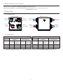 4
4
-
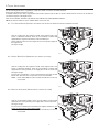 5
5
-
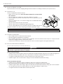 6
6
-
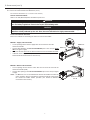 7
7
-
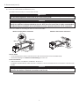 8
8
-
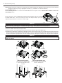 9
9
-
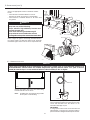 10
10
-
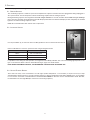 11
11
-
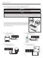 12
12
-
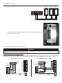 13
13
-
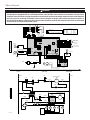 14
14
-
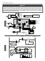 15
15
-
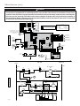 16
16
-
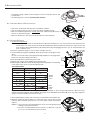 17
17
-
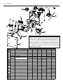 18
18
-
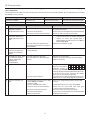 19
19
-
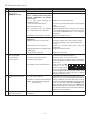 20
20
-
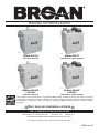 21
21
-
 22
22
-
 23
23
-
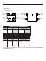 24
24
-
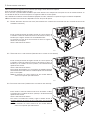 25
25
-
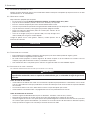 26
26
-
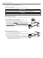 27
27
-
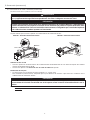 28
28
-
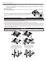 29
29
-
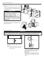 30
30
-
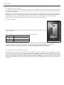 31
31
-
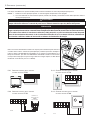 32
32
-
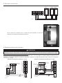 33
33
-
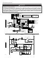 34
34
-
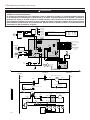 35
35
-
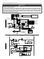 36
36
-
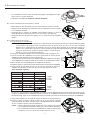 37
37
-
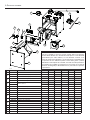 38
38
-
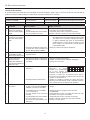 39
39
-
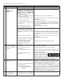 40
40


Broan HRV90T Guía de instalación
- Tipo
- Guía de instalación
en otros idiomas
- English: Broan HRV90T Installation guide
Artículos relacionados
-
Broan HRV90H Guía de instalación
-
-
Broan ERV110S Manual de usuario
-
-
-
NuTone Fresh Air System ERV90HCT Installation Instructions Manual
-
-
-
-
Broan ERVS100S Guía de instalación
