
22635 rev. 03
INSTALLATION GUIDE FOR
ERV120T, HRV120T,
ERV120S, HRV120S
ERV110T
AND ERV110S UNITS
ERV and HRV with side ports
ERV120S*
HRV120S*
and ERV110S
VB0238
VB0237
RESIDENTIAL USE ONLY
READ AND SAVE THESE INSTRUCTIONS
! !
ERV and HRV with top ports
ERV120T*
HRV120T*
and ERV110T
*These products earned the ENERGY STAR
®
by meeting strict energy efficiency guidelines set by Natural Resources
Canada and the US EPA. They meet ENERGY STAR requirements only when used in Canada.
Broan-NuTone LLC; Hartford, Wisconsin www.broan.com 800-543-3055
REGISTER YOUR PRODUCT ONLINE AT: www.broan.com/register
For additional information - visit www.broan.com

2
Because of the large amount of models covered by this publication, the illustrations are typical ones. Some details of your unit may be
slightly different than the ones shown.
Please take note that this manual uses the following symbols to emphasize particular information:
NOTE: Indicates supplementary information needed to fully complete an instruction.
WARNING
Identifies an instruction which, if not followed, might cause serious personal injuries including possibility of death.
!
CAUTION
Identifies an instruction which, if not followed, may severely damage the unit and/or its components.
ABOUT THIS MANUAL
ABOUT THESE UNITS
LIMITATION
For residential (domestic) installation only. Installation work and electrical wiring must be done by a qualified person(s) in accordance with
all applicable codes and standards, including fire-rated construction codes and standards.
WARNING
TO REDUCE THE RISK OF FIRE, ELECTRIC SHOCK, OR INJURY TO PERSON(S) OBSERVE THE FOLLOWING:
1. Use this unit only in the manner intended by the manufacturer. If you have questions, contact the manufacturer at the address or
telephone number listed in the warranty.
2. Before servicing or cleaning the unit, disconnect power cord from electrical outlet.
3. This unit is not designed to provide combustion and/or dilution air for fuel-burning appliances.
4. When cutting or drilling into wall or ceiling, do not damage electrical wiring and other hidden utilities.
5. Do not use this unit with any solid-state speed control device other than following wall control:
6. This unit must be grounded. The power supply cord has a 3-prong grounding plug for your personal safety. It must be plugged into
a mating 3-prong grounding receptacle, grounded in accordance with the national electrical code and local codes and ordinances.
Do not remove the ground prong. Do not use an extension cord.
7. Do not install in a cooking area or connect directly to any appliances.
8. Do not use to exhaust hazardous or explosive materials and vapors.
9. When performing installation, servicing or cleaning these units, it is recommended to wear safety glasses and gloves.
10. Due to the weight of the unit, two installers are recommended to perform installation.
11. When applicable local regulation comprise more restrictive installation and/or certification requirements, the aforementioned
requirements prevail on those of this document and the installer agrees to conform to these at his own expense.
CAUTION
1. To avoid prematurate clogged filters, turn OFF the unit during construction or renovation.
2. Please read specification label on product for further information and requirements.
3. Be sure to duct air outdoors – Do not intake/exhaust air into spaces within walls or ceiling or into attics, crawl spaces, or garage.
4. Intended for residential installation only in accordance with the requirements of NFPA 90B.
5. Do not run any air ducts directly above or closer than 2 ft to any furnace or its supply plenum, boiler, or other heat producing appliance.
If a duct has to be connected to the furnace return plenum, it must be connected not closer than 9’ 10” from this plenum connection to
the furnace.
6. The ductwork is intended to be installed in compliance with all local and national codes that are applicable.
7. When leaving the house for a long period of time (more than two weeks), a responsible person should regularly check if the unit
operates adequately.
8. If the ductwork passes through an unconditioned space (e.g.: attic), the unit must operate continuously except when performing
maintenance and/or repair. Also, the ambient temperature of the house should never drop below 65°F.
MAIN CONTROLS AUXILIARY CONTROLS
VT8W, VT7W, VT4W OR VT6W VB60W, VB20W AND 59W

3
TABLE OF CONTENTS
1. S ERVICE PARTS ................................................................................................................................. 4-5
2. T
YPICAL INSTALLATIONS ....................................................................................................................... 6-7
2.1 FULLY DUCTED SYSTEM ..........................................................................................................................................6
2.2 C
ENTRAL DRAW POINT ...........................................................................................................................................6
2.3 S
IMPLIFIED INSTALLATION .........................................................................................................................................6
2.4 A
TTIC INSTALLATION (FOR ERV UNITS ONLY) ..............................................................................................................7
3. INSTALLATION ....................................................................................................................................7-11
3.1 INSPECT THE CONTENT OF THE BOX ..........................................................................................................................8
3.2 L
OCATING THE UNIT ...............................................................................................................................................8
3.3 U
NIT PREPARATION ................................................................................................................................................8
3.4 H
OW TO HANG THE UNIT ........................................................................................................................................9
3.5 P
LANNING OF THE DUCTWORK..................................................................................................................................9
3.6 I
NSTALLING THE DUCTWORK AND REGISTERS ........................................................................................................9-11
3.7 C
ONNECTING THE DUCTS TO THE UNIT ....................................................................................................................10
3.8 I
NSTALLING 2 EXTERIOR HOODS ............................................................................................................................. 11
3.9 I
NSTALLING THE TANDEM
®
TRANSITION KIT ................................................................................................................11
4. CONTROLS .................................................................................................................................... 12-14
4.1 INTEGRATED CONTROL ..........................................................................................................................................12
4.2 E
LECTRICAL CONNECTION TO OPTIONAL WALL CONTROLS ..........................................................................................12
5. ELECTRICAL CONNECTION TO THE FURNACE ..............................................................................................14
6. WIRING DIAGRAMS ......................................................................................................................... 15-16
7. B ALANCING THE UNIT .............................................................................................................................17
8. CONNECTING THE DRAIN (HRV UNITS ONLY) ...........................................................................................18
9. TROUBLESHOOTING ......................................................................................................................... 19-21

4
1. SERVICE PARTS
VL0053
1
2
3
4
7
5
6
11
12
13
3
14
8
9
10

5
NO.DESCRIPTION PART NO.
ERV110S
SIDE PORTS
ERV110T
TOP PORTS
ERV120S
SIDE PORTS
HRV120S
SIDE PORTS
HRV120T
TOP PORTS
ERV120T
TOP PORTS
1OVAL PORT (FITS 5” DIAMETER DUCTS) SV16040 1 1 1 1 1 1
2DOOR LATCH WITH SCREWS SV16035 2 2 2 2 2 2
3OVAL PORT WITH INTEGRATED BALANCING DAMPER SV16041 2 2 2 2 2 2
4
MOTOR & WHEEL ASSEMBLY (5 µF MOTOR CAPACITOR
AND INLET RING INCLUDED)
SV18301 2 2 2 2 2 2
5CAPACITOR 5 µF (2) SV16042 2 2 1 1 1 1
6CAPACITOR 18 µF SV61127 1 1 1 1 1 1
7ELECTRONIC BOARD
SV16038 1 1 1 N/A N/A 1
SV62257 N/A N/A N/A 1 1 N/A
8ERV
FOAM FILTER (2) SV16031 2 2 1 N/A N/A 1
9ERV CORE (WITH 2 FILTERS) SV16037 1 1 1 N/A N/A 1
10 DRAIN CONNECTOR KIT SV03203 N/A N/A N/A 1 1 N/A
11 DOOR ASSEMBLY SV16096 1 1 1 1 1 1
12 BLUE HRV CORE (WITH 2 FILTERS) SV18300 N/A N/A N/A 1 1 N/A
13 HRV FOAM FILTER SV16032 N/A N/A N/A 1 1 N/A
14 MOTORIZED DAMPER PORT ASSEMBLY SV16029 1 1 1 1 1 1
15* ES TRANSFORMER SV18302 1 1 1 1 1 1
16* GREEN TERMINAL BLOCK SV16416 1 1 1 1 1 1
REPLACEMENT PARTS AND REPAIR
In order to ensure your ventilation unit remains in good working condition, you must use Broan genuine replacement parts only.
The Broan genuine replacement parts are specially designed for each unit and are manufactured to comply with all the applicable
certification standards and maintain a high standard of safety. Any third party replacement part used may cause serious damage
and drastically reduce the performance level of your unit, which will result in premature failing. Also, Broan recommends to contact a
certified service depot for all replacement parts and repairs.
* NOT SHOWN.
1. SERVICE PARTS (CONT'D)

6
2. TYPICAL INSTALLATIONS
Installations may vary according to the type of unit and the ports configuration (top or sides). Use the following illustrations as guidelines
to help you decide on how the unit will be installed.
All the units should be hung from the joists.
In every case, bathroom fans and a range hood should be used to exhaust stale air. Also, for homes with more than one level, we
recommend one exhaust register at the highest level.
There are 3 installation methods: Fully ducted, Central Draw Point and Simplified Installation.
NOTE: An electrical outlet has to be available within 3 feet of the unit.
2.1 FULLY DUCTED SYSTEM (PRIMARILY FOR HOMES WITH RADIANT HOT WATER OR ELECTRIC BASEBOARD HEATING)
VH0055
Stale air coming from the registers located at the highest level of the house
is exhausted outdoors. Fresh air from outdoors is filtered and supplied by
the register located in the lowest liveable level.
Homes with more than one level require at least one exhaust register at the
highest level.
See figure at right.
2.2 CENTRAL DRAW POINT (CONNECTION TO A FORCED AIR SYSTEM)
VH0056
Stale air coming from the registers located at the highest level of the house
is exhausted outdoors. Fresh air from outdoors is filtered and supplied to the
return (plenum) or the supply duct of the forced air unit. See figure at right.
For this type of installation, it is not essential that the forced air system
blower runs when the unit is in operation, but we recommend it.
NOTE: Home with multiple forced air systems should have one unit on each
system.
2.3 SIMPLIFIED INSTALLATION (CONNECTION TO A FORCED AIR SYSTEM)
VH0057
Stale air is exhausted outdoors. Fresh air from outdoors is filtered and
supplied to the return (plenum) or the supply duct of the forced air unit.
See figure at right.
To avoid cross-contamination and achieve the highest efficiencies, the
forced air system blower must always be ON.
NOTE: Home with multiple forced air systems should have one unit on each
system.

7
2. TYPICAL INSTALLATIONS (CONT’D)
2.4 ATTIC INSTALLATION (FOR ERV UNITS ONLY)
All 3 types of installations can be used in the attic (Fully ducted system, Central Draw Point or Simplified). The example shown
below is a Simplified installation (connection to a forced air system).
NOTE: To get the most of your ERV unit, the ambient temperature around the unit should be conditioned. If the unit has to be
installed in an unconditioned space, the heat gains or losses from the unit and the ducts could increase the operation
costs of the unit.
CAUTION
• Due to the potential temperature difference between the attic and the rest of the house, all unit ducts must be
insulated.
• The attic temperature must always be above 32°F and under 149°F.
Stale air is exhausted outdoors. Fresh air from outdoors
is filtered and supplied to the return (plenum) of the
forced air unit. See figure at right.
To avoid cross-contamination and achieve the highest
efficiencies, the forced air system blower must always
be ON.
NOTE: Home with multiple forced air systems should
have 1 unit on each system.
VH0102
3. INSTALLATION
3.1 INSPECT THE CONTENTS OF THE BOX
• Inspect the exterior of the unit for shipping damage. Ensure that there is no damage to the door, door latches, power cord, etc.
• Remove and discard both transport brackets (A) and open the door. Discard the styrofoam
fillers (only in ERV units) and remove the hardware kit from the unit. Inspect the interior
of the unit for damage. Ensure that heat or energy recovery core, core filters, insulation,
dampers, etc. are all intact.
3.2 LOCATING THE UNIT
Choose an appropriate location for the unit.
• Within an area of the house where the ambient temperature is kept between 65°F and 104°F.
• So as to provide easy access to the interior of the unit, for quarterly and annual maintenance.
• Close to an exterior wall, so as to limit the length of the insulated flexible duct to and from the unit.
• Away from hot chimneys and other fire hazards.
• Allow for a power source (standard 3-prong grounding outlet).
• For HRV units ONLY: Close to a drain. If no drain is close by, use a pail to collect run-off.
3.3 UNIT PREPARATION
All these units are equipped with 2 ports having integrated balancing damper. Turn the thumb screw
(B) clockwise to manually open and adjust the damper (C). Set both Fresh air to building port and
Exhaust air to outdoors port to wide open position.
HRV units: Set the Fresh air to building port to wide open position, and adjust the Exhaust air
to outdoors port to 3rd notch.
NOTE: If the unit needs to be balanced, adjust the damper of the Exhaust air to outdoors port to
wide open position. See Section 7.
ERV units: Set both Fresh air to building port and Exhaust air to outdoors port to wide open
position.
VD0183
A
V
J003
2
B
C
Port with integrated balancing
damper - Top view

8
3. INSTALLATION (CONT’D)
3.4 HOW TO HANG THE UNIT
Hang the unit with the 4 chains, hooks and springs
provided.
CAUTION
Make sure the unit is level.
VD0184
VD0185
VD0187
If there is not enough space on top of the unit, slightly bend the hooks and install them
lower on the unit. See figure at right.
3.5 PLANNING OF THE DUCTWORK
• Keep it simple. Plan for a minimum of bends and joints.
• Keep the length of insulated ducts to a minimum.
• Do not ventilate crawl spaces or cold rooms. Do not attempt to recover the exhaust air from a dryer or a range hood. This would
cause clogging of the filters and recovery module.
• If the house has two floors or more, be sure to plan for at least one exhaust register on the highest lived-in level.
3.6 INSTALLING THE DUCTWORK AND REGISTERS
3.6.1 FULLY DUCTED SYSTEM (AS ILLUSTRATED IN SECTION 2.1)
Stale air exhaust ductwork:
• Install the stale air exhaust registers where the contaminants are produced: Kitchen, living room, etc. Position the registers as far
from the stairway as possible and in such a way that the air circulates in all the lived-in spaces in the house.
• If a register is installed in the kitchen, it must be located at least 4 feet from the range.
• Install the registers 6 to 12 inches from the ceiling on an interior wall OR install them in the ceiling.
Fresh air distribution ductwork:
• Install the fresh air distribution registers in bedrooms, dining rooms, living room and basement.
• Keep in mind that the fresh air registers must be located as far as possible from the stale air registers.
• Install the registers in the ceiling OR 6 to 12 inches from the ceiling on an interior wall. The duct length should be at least 15’.
(The fresh air will then flow through the room and mix with room air, ensuring a continuous renewed airflow.)
• If a register must be floor installed, direct the airflow up the wall.
WARNING
Never install a stale air exhaust register in a closed room where a combustion device operates, such as a gas furnace, a gas
water heater or a fireplace.
!

9
3. INSTALLATION (CONT’D)
3.6 INSTALLING THE DUCTWORK AND REGISTERS (CONT’D)
3.6.2 SIMPLIFIED INSTALLATION (AS ILLUSTRATED IN SECTION 2.3)
There are 2 methods for connecting the unit to the furnace/air handler:
Method 1: Supply-return connection Method 2: Return-return
Stale air intake:
• Cut an opening into the furnace/air handler return duct not less than 10 feet from the furnace/air handler (A+B).
• Connect this opening to the Exhaust air from building port of the HRV/ERV.
Fresh air distribution:
• Same instructions as for Method 1 or Method 2, Section 3.6.2.
For Method 2 (Return-return), make sure there is a distance of at least 3 feet between the 2 connections to the furnace/air
handler.
NOTE: For Method 1, it is not essential to synchronize the furnace blower operation with the unit operation, but we recommend it.
WARNING
When performing duct connections, always use approved tools and materials. Respect all corresponding laws and/or safety
regulations. Please refer to your local building code.
!
CAUTION
When performing duct connections to the furnace supply duct, this duct must be sized to support the additional airflow
produced by the HRV/ERV. Also, use a steel duct. For a Return-Return installation, the furnace blower must be in operation
when the HRV/ERV is in operation.
B
A
VJ0038
B
A
VJ0037
STEEL DUCT
MINIMUM 18"
A+B= NOT LESS
THAN 10'
M
INIMUM 3'
A+B=
NOT LESS
THAN 10'
CAUTION
If using Method 2, make sure the furnace/air handler blower operation is synchronized with the unit operation! See Section 5.

10
3.7 CONNECTING THE DUCTS TO THE UNIT
NOTE: All units ports were created to be connected to ducts having a minimum of 5” diameter, but if need be, they can be connected
to bigger sized ducts by using an appropriate transition (e.g.: 5” diameter to 6” diameter transition).
Insulated flexible ducts:
All units have both Fresh air to building and Exhaust air to outdoors ports equipped with integrated balancing damper. Prior to
install the insulated flexible ducts on, ensure these both ports have their dampers set to wide open position (See Section 3.3)
CAUTION
Make sure the balancing dampers are set to wide open position before connecting the ducts to the ports.
Pull back the insulation to expose the flexible duct.
Attach the flexible duct to the port using tie wrap.
Pull the insulation over the joint and tuck in between the inner and outer rings of the double collar, then pull down the vapor barrier
(shaded part in illustrations below) over the insulation and over the outer ring of double collar.
Apply duct tape to the joint making an airtight seal. Avoid compressing the insulation when pulling the tape
tightly around the joint. Compressed insulation loses its R value and causes water dripping due to condensation on the exterior
surface of the duct.
Rigid ducts:
Use a small length (6” lenght) of flexible duct to connect the rigid duct to the ports in order to avoid vibration transmissions. Use
tie-wraps to perform connections, then seal with duct tape.
CAUTION
Do not use screws to connect the rigid ducts to the ports.
Use the following procedure for connecting the insulated flexible ducts to the port of the unit (Exhaust air to outdoors and Fresh
air from outdoors ports).
CAUTION
If ducts have to go through an unconditioned space (e.g.: attic), always use insulated ducts.
VJ0120
CAUTION
Make sure the vapor barrier on the insulated ducts does not tear during installation to avoid condensation within the
ducts.
3. INSTALLATION (CONT’D)

11
3.8 INSTALLING 2 EXTERIOR HOODS
Choose an appropriate location to install the exterior hoods:
• There must be a inimum distance of 6’ between the hoods to avoid cross-contamination
• There must be a minimum distance of 18” from the ground
Refer to figure below for connecting insulated ducts to the exterior hoods. An “Anti-gust intake hood” should be installed in regions
where a lot of snow is expected to fall.
WARNING
Make sure the intake hood is at least 6 feet (1.8 m) away from any of the following:
• Dryer exhaust, high efficiency furnace vent, central vacuum vent
• Gas meter exhaust, gas barbecue-grill
• Any exhaust from a combustion source
• Garbage bin and any other source of contamination
!
VD0028
EXHAUST HOOD
INTAKE HOOD
TAPE AND DUCT TIE
18"
6'
18"
18"
6'
6" Ø
O
PTIONAL DUCT
LOCATION
3.9 INSTALLING THE TANDEM
®
TRANSITION* KIT
If desired, a Tandem transition kit can be used instead of 2 exterior hoods; but take in
account this device will generate additional 0.23 in. w.g. static pressure.
The joist opening needed to install the Tandem
®
transition must be 9¾” minimum. The
maximum height of the Tandem transition is 8¾”.
To connect the insulated flexible ducts to the Tandem transition (Exhaust air to outdoors
and Fresh air from outdoors), follow the instructions included with the Tandem transition kit
(part no. VTYIK1).
*Patented.
VR0003
Tandem transition kit
3. INSTALLATION (CONT’D)

12
4. CONTROLS
4.1 INTEGRATED CONTROL
All units are equipped with an integrated control, located under the unit, in front of the
electrical compartment. Use the push button (1) to control the unit. The LED (2) will then
shows on which mode the unit is in. Refer to table below.
WARNING
Risk of electric shock. Before performing
any maintenance or servicing, always
disconnect the unit from its power source.
AVERTISSEMENT
Danger d’électrocution. Débranchez
toujours l’appareil avant d’entreprendre
des travaux d’entretien ou de réparation.
CAUTION
Unscrew both screws to open the electrical
compartment. To completely remove, detach
from its retention wire inside.
ATTENTION
Dévisser les deux vis pour ouvrir le compartiment
électrique. Pour retirer complètement, le
détacher de son fil de rétention intérieur.
No li gh t OFF or remote controled
Amber light LOW speed
Green ligh HIGH speed
Blinking light See User Manual
Sans lumière Arrêté ou contrôlé
par contrôle mural
Lumière ambre Basse vitesse
Lumière verte Haute vitesse
Clignotant Voir guide d’utilisation
VD0182
12
LED COLOR RESULTS
AMBER UNIT IS ON LOW SPEED
GREEN UNIT IS ON HIGH SPEED
NO LIGHT UNIT IS OFF OR CONTROLLED BY A MAIN CONTROL
If a problem occurs during the unit operation, its integrated control LED (2) will blink. The color of the blinking light depends on the type of
error detected. Refer to Section 8B, TROUBLESHOOTING on page 21 for further details.
4.1.1 B
OOT SEQUENCE
The unit boot sequence is similar to a personal computer boot sequence. Each time the unit is plugged after being unplugged, or
after a power failure, the unit will perform a 30-second booting sequence before starting to operate. During the booting sequence,
the integrated control LED will light GREEN or AMBER for 5 seconds, and then will shut off for 2 seconds. After that, the LED will
light RED for the rest of the booting sequence. During this RED light phase, the unit is checking and resetting the motorized damper
position. Once the motorized damper position completely set, the RED light turns off and the booting sequence is done.
NOTE: No command will be taken until the unit is fully booted.
4.2 ELECTRICAL CONNECTION TO OPTIONAL WALL CONTROLS
For more convenience, this unit can also be controlled using an optional main wall control.
NOTES: 1. The integrated control must be turned OFF to use an optional main control.
2. If an optional auxiliary control is used, if activated, this auxiliary control will override the optional main control.
WARNING
Always disconnect the unit before making any connections. Failure in disconnecting power could result in electric shock or
damage of the wall control or electronic module inside the unit.
!
CAUTION
Never install more than one optional main wall control per unit. Make sure that the wires do not short-circuit between
themselves or by touching any other components on the wall control. Avoid poor wiring connections. To reduce electrical
interference (noise) potential, do not run wall control wiring next to control contactors or near light dimming circuits, electrical
motors, dwelling/building power or lighting wiring, or power distribution panel.
Use the terminal connector included in the installation kit to perform the electrical
connection for main and optional wall controls. Check if all wires are correctly inserted in
their corresponding holes in the terminal block. (A wire is correctly inserted when its orange
receptacle is lower than another one without wire. On illustration at right, wire A is correctly
inserted, but not wire B.)
Splice back the end of the cable to access the 4 wires. Strip the end of each wire. Connect
each wire to its corresponding terminal: YELLOW wire to “Y’’, RED wire to “R’’, GREEN wire
to “G’’ and BLACK wire to “B’’. Check if all wires are correctly inserted in their corresponding
holes in the terminal block.
Connect the auxiliary control cable, if installed (not shown).
VE0272
A
B
4.1. 2 S
ETTING EXTENDED DEFROST
These units are factory set to normal defrost. In cold region (outdoor temperature -17°F and lower), it may be necessary to setup
extended defrost. During the first 2 seconds of booting sequence, while the integrated control LED is GREEN, press on push
button for 3 seconds to set the unit in extended defrost; the LED will blink AMBER to show the unit is in extended defrost mode.
After that, the LED will shut off, then light RED (the unit returns in its booting sequence).

13
4. CONTROLS (CONT’D)
4.2 ELECTRICAL CONNECTION TO OPTIONAL WALL CONTROLS (CONT'D)
4.2.3 ELECTRICAL CONNECTION
TO VT4W MAIN WALL CONTROL
NO C NC I OC OL Y R G B
B G
G
B
Y
VE0328A
Y
4.2.4 ELECTRICAL CONNECTION TO OPTIONAL AUXILIARY WALL CONTROLS
Once the wall control(s) connections have been made, insert the terminal connector in the bottom of the unit, on the electrical compartment
front face.
WARNING
Risk of electric shock. Before performing
any maintenance or servicing, always
disconnect the unit from its power source.
AVERTISSEMENT
Danger d’électrocution. Débranchez
toujours l’appareil avant d’entreprendre
des travaux d’entretien ou de réparation.
CAUTION
Unscrew both screws to open the electrical
compartment. To completely remove, detach
from its retention wire inside.
ATTENTION
Dévisser les deux vis pour ouvrir le compartiment
électrique. Pour retirer complètement, le
détacher de son fil de rétention intérieur.
No li gh t OFF or remote controled
Amber light LOW speed
Green ligh HIGH speed
Blinking light See User Manual
Sans lumière Arrêté ou contrôlé
par contrôle mural
Lumière ambre Basse vitesse
Lumière verte Haute vitesse
Clignotant Voir guide d’utilisation
VD0182
TERMINAL
CONNECTOR
MAIN WALL
CONTROL
VT4W
REAR VIEW
4.2.2 ELECTRICAL CONNECTION
TO VT7W MAIN WALL CONTROL
NO C NC I OC OL Y R G B
VE0250
4.2.1 ELECTRICAL CONNECTION
TO VT8W MAIN WALL CONTROL
NO C NC I OC OL Y R G B
VE0181
SMART
SET
MODE
PREF
4.2.4 ELECTRICAL CONNECTION
TO VT6W MAIN WALL CONTROL
NO C NC I OC OL Y R G B
VE0187
NO C NC I OC OL Y R G B
VE0371
59W
VB60W
OR VB20W

14
5. ELECTRICAL CONNECTION TO THE FURNACE
WARNING
Never connect a 120-volt AC circuit to the terminals of the furnace interlock (standard wiring). Only use the low voltage class
2 circuit of the furnace blower control.
!
For a furnace connected to a cooling system:
On some older thermostats, energizing the “R” and “G” terminals at the furnace has the effect of energizing “Y” at the thermostat and
thereby turning on the cooling system. If you identify this type of thermostat, you must use the ALTERNATE FURNACE INTERLOCK WIRING.
STANDARD FURNACE INTERLOCK WIRING ALTERNATE FURNACE INTERLOCK WIRING
W R G
Y
W
R
G
C
Y
UNIT TERMINAL CONNECTOR
THERMOSTAT
TERMINALS
FOUR
WIRES
TWO WIRES
heating only
FURNACE
24-VOLT
TERMINAL BLOCK
TWO WIRES
COOLING SYSTEM
NO C NC I OC OL Y R G B
W R G Y
W
R
Y
R
G
Y
C
THERMOSTAT
TERMINAL
4 WIRES
2 WIRES
heating only
wiring
nuts
FURNACE
24-VOLT
TERMINAL BLOCK
2 WIRES
COOLING SYSTEM
NO
NC
C
UNIT TERMINAL CONNECTOR
NO C NC I OC OL Y R G B
VE0108A

15
6. WIRING DIAGRAMS
WARNING
• Risk of electric shocks. Before performing any maintenance or servicing, always disconnect the unit from its power source.
• This product is equipped with an overload protection (fuse). A blown fuse indicates an overload or a short-circuit situation.
If the fuse blows, unplug the product and check the polarity and voltage output from the outlet. Replace the fuse as per the
servicing instructions (refer to wiring diagram for proper fuse rating) and verify the product. If the replaced fuse blows, it may
be a short-circuit and the product must be discarded or returned to an authorized service center for examination and/or repair.
!
Field wiring
remote control
(see notes 3 & 4)
120 V, 60 Hz
W1
J5
J7
J6
J4
ELECTRONIC
ASSEMBLY
1
2
3
1
2
1
2
1
2
3
1234
12
12345
12345
J8
J9
J11
J10
12
J12
J13
J14
10
9
8
7
6
5
4
3
2
1
BK
24 V
class 2
9.5 V
class 2
120V, 60Hz
Neutral
120 V, 60 Hz
Line
CPU
K2
K4
K5
J5-2
J10-1J10-2
See note 1
120 V
106 V
81 V
neutral
Door interlock switch
(magnetically actuated
Exhaust fan
motor
1234512
12
J3
J2
J1
t°
Damper motor
BK
Override
switch
Furnace blower interlock
J14-1 : NO
J14-2 : COM
J14-3 : nc
(optional; see notes 3, 5)
DAMPER
ELECTRONIC ASSEMBLY
Defrost
temperature sensor
WIRING DIAGRAM
LOGIC DIAGRAM
Exhaust fan motor
Supply fan motor
J5-1
J5-3
J7-2
J7-1
J4-1
J4-3
J6-2
J6-1
K1
K3
K2
24 V
class 2
9.5 V
class 2
120 V
neutral
J9-1
J9-2
J9-3
J4-2
J9-4
Exhaust fan motor
capacitor
Supply fan motor
capacitor
J8-1
J8-2
J8-4
J8-5
K4
J12-2
J12-1
A1
Damper motor
J3-2
J3-1
J2-2
J2-1
F1
J12-5
J12-4
J12-3
J2-3
J2-4
J2-5
Door interlock switch
J11-2
J11-1
K1
K3
K5
J14-3
J14-1
J14-2
Furnace
blower
interlock
(optional; see
notes 3, 5)
J14-4
J14-5
J14-6
J14-7
J14-8
J14-9
J14-10
Override
switch
(optional; see
notes 3, 4)
Field wiring
remote
control (see
notes 3, 4)
ICP
BK
YRG
W W
BK
W
BL
G
BK
BL
BN
BN
R
R
R
R
BK
BL
Exhaust fan
motor
capacitor
Supply fan
motor
capacitor
Supply fan
motor
G
G
O
O
Y
Y
BK
W
A2
A2
M3
T1
S1
R1
A1
F1
M1
C1
C2
M2
(optional; see
notes 3 & 4)
VE0324A
COLOR CODE
BK BLACK
BL BLUE
BN BROWN
G GREEN
RRED
W WHITE
Y YELLOW
nc no connection
Critical characteristic.
reed switch)
JU1
1
23
MED HI
321
HI MED
JU1
NOTES
1. Use specified UL listed/CSA Certified line fuse
(3A, 3AG Type).
2. If any of the original wire, as supplied, must
be replaced, use the same equivalent wire.
3. Field wiring must comply with applicable
codes, ordinances and regulations.
4. Remote controls (class 2 circuit) available,
see instruction manual.
5. Furnace fan circuit must be class 2 circuit only.
Ref
1
Ref
1
FAN MOTORS SPEED SELECTION
SETTING Ref 1 FAN SPEEDS (Voltage)
Factory shipped Low - High (106)
Med-High select Med (64) - High (106)
Low-Med select Low - Med (81)
BL BL
BK R
BL BL
GR R
PBL
BK R
71 V
64 V
57 V
R
BL
BL
R
BK
P
P
BN
BN
GR
GR
nc
nc
nc
GR GREY
O ORANGE
P PURPLE
O
O
Y
Y
106 V
81 V
71 V
64 V
57 V
BK
W
BL
R
P
BN
GR
BK
W
BL
R
P
BN
GR
120 V
106 V
81 V
71 V
64 V
57 V
R
nc
BK
Low speed
capacitor
C1
BK
BL
MED
R
LO
BK
Low speed
capacitor
BK
Line voltage factory wiring
Class 2 low voltage factory wiring
Class 2 low voltage field wiring
Setting for test purpose only
1
23
MED HI
BL BL
BK R
Ref 1
JU1
Low - High (120)
ERV110T AND ERV110S

16
6. WIRING DIAGRAMS (CONT’D)
WARNING
• Risk of electric shocks. Before performing any maintenance or servicing, always disconnect the unit from its power source.
• This product is equipped with an overload protection (fuse). A blown fuse indicates an overload or a short-circuit situation.
If the fuse blows, unplug the product and check the polarity and voltage output from the outlet. Replace the fuse as per the
servicing instructions (refer to wiring diagram for proper fuse rating) and verify the product. If the replaced fuse blows, it may
be a short-circuit and the product must be discarded or returned to an authorized service center for examination and/or repair.
!
Field wiring
remote control
(see notes 3 & 4)
120 V, 60 Hz
W1
J5
J7
J6
J4
ELECTRONIC
ASSEMBLY
1
2
3
1
2
1
2
1
2
3
1234
12
12345
12345
J8
J9
J11
J10
12
J12
J13
J14
10
9
8
7
6
5
4
3
2
1
BK
24 V
class 2
9.5 V
class 2
120V, 60Hz
Neutral
120 V, 60 Hz
Line
CPU
K2
K4
K5
J5-2
J10-1J10-2
Line voltage factory wiring
Class 2 low voltage factory wiring
Class 2 low voltage field wiring
See note 1
120 V
106 V
81 V
neutral
Door interlock switch
(magnetically actuated
Exhaust fan
motor
1234512
12
J3
J2
J1
t°
Damper motor
BK
Override
switch
Furnace blower interlock
J14-1 : NO
J14-2 : COM
J14-3 : nc
(optional; see notes 3, 5)
DAMPER
ELECTRONIC ASSEMBLY
Defrost
temperature sensor
WIRING DIAGRAM
LOGIC DIAGRAM
Exhaust fan motor
Supply fan motor
J5-1
J5-3
J7-2
J7-1
J4-1
J4-3
J6-2
J6-1
K1
K3
K2
24 V
class 2
9.5 V
class 2
120 V
neutral
J9-1
J9-2
J9-3
J4-2
J9-4
Exhaust fan motor
capacitor
Supply fan motor
capacitor
J8-1
J8-2
J8-4
J8-5
K4
J12-2
J12-1
A1
Damper motor
J3-2
J3-1
J2-2
J2-1
F1
J12-5
J12-4
J12-3
J2-3
J2-4
J2-5
Door interlock switch
J11-2
J11-1
K1
K3
K5
J14-3
J14-1
J14-2
Furnace
blower
interlock
(optional; see
notes 3, 5)
J14-4
J14-5
J14-6
J14-7
J14-8
J14-9
J14-10
Override
switch
(optional; see
notes 3, 4)
Field wiring
remote
control (see
notes 3, 4)
ICP
BK
YRG
W W
BK
W
BL
G
BK
BL
BN
BN
R
R
R
R
BK
BL
Exhaust fan
motor
capacitor
Supply fan
motor
capacitor
Supply fan
motor
G
G
O
O
Y
Y
BK
W
A2
A2
M3
T1
S1
R1
A1
F1
M1
C1
C2
M2
(optional; see
notes 3 & 4)
VE0309A
COLOR CODE
BK BLACK
BL BLUE
BN BROWN
G GREEN
RRED
W WHITE
Y YELLOW
nc no connection
Critical characteristic.
reed switch)
JU1
1
23
MED HI
321
HI MED
JU1
NOTES
1. Use specified UL listed/CSA Certified line fuse
(3A, 3AG Type).
2. If any of the original wire, as supplied, must
be replaced, use the same equivalent wire.
3. Field wiring must comply with applicable
codes, ordinances and regulations.
4. Remote controls (class 2 circuit) available,
see instruction manual.
5. Furnace fan circuit must be class 2 circuit only.
Ref
1
Ref
1
FAN MOTORS SPEED SELECTION
SETTING Ref 1 LOW SPEED SETTING
Factory shipped Low (71V)
Optionnal Low 1 Low (81V)
Optionnal Low 2 Low (64V)
BN R
PR
GR R
71 V
64 V
57 V
R
BL
BL
R
BK
P
P
BN
BN
GR
GR
nc
nc
nc
GR GREY
O ORANGE
P PURPLE
O
O
Y
Y
106 V
81 V
71 V
64 V
57 V
BK
W
BL
R
P
BN
GR
BK
W
BL
R
P
BN
GR
120 V
106 V
81 V
71 V
64 V
57 V
R
nc
BK
Low speed
capacitor
C1
BK
BL
MED
R
LO
BK
Low speed
capacitor
BK
Optionnal Low 3 Low
BK R
(Low speed capacitor)
ERV120T, ERV120S, HRV120T AND HRV120S

17
7. BALANCING THE UNIT
To avoid balancing, the difference between stale air ducts total length and fresh air ducts total length must not exceed 50 ft. However, even
if the stale air ducts and fresh air ducts lengths are almost equal, your local building codes may require balancing the unit.
If the unit does not need to be balanced, shut all the pressure taps (located on the unit door) with the small plastic plugs included in the
hardware kit.
7.1 WHAT YOU NEED TO BALANCE THE UNIT
• A magnehelic gauge capable of measuring 0 to 0.5 inch of water (0 to 125 Pa) and 2 plastic
tubes.
• The balancing chart located on the unit door.
7.2 PRELIMINARY STAGES TO BALANCE THE UNIT
• Seal all the unit ductwork with tape. Close all windows and doors.
• Turn off all exhaust devices such as range hood, dryer and bathroom fans.
• Make sure the integrated balancing dampers are fully open. Turn the thumb screw (A) clockwise to
manually open the dampers. Both are located on the Exhaust air to outdoors port and on Fresh air
to building port.
• Make sure all filters are clean (if it is not the first time you balance the unit).
7.3 BALANCING PROCEDURE
1. Set the unit to high speed.
Make sure that the furnace/air handler blower is ON if the installation is in any way
connected to the ductwork of the cold air return. If not, leave furnace/air handler blower
OFF. If the outdoor temperature is below 32°F, make sure the unit is not running in defrost
while balancing. (By waiting 10 minutes after plugging the unit in, you are assured that the
unit is not in a defrost cycle.)
2. Place the magnehelic gauge on a level surface and adjust it to zero.
3. Connect tubing from gauge to exhaust air flow pressure taps (see diagram at right).
Be sure to connect the tubes to their appropriate high/low fittings. If the gauge drops below
zero, reverse the tubing connections.
NOTE: It is suggested to start with the exhaust air flow reading because the exhaust
has typically more restriction than the fresh air, especially in cases of fully ducted
installations or source point ventilation. Place the magnehelic gauge upright and level. Record equivalent air flow of the
reading according to the balancing chart.
4. Move tubing to fresh air flow pressure taps (see diagram). Adjust the fresh air balancing damper until the fresh air flow is
approximately the same as the exhaust air flow. If fresh air flow is less than exhaust air flow, then go back and adjust the exhaust
balancing damper to equal the fresh air flow.
5. Secure both dampers thumb screw in place with tape.
6. Write the required air flow information on a label and stick it near the unit for future reference (date, maximum speed air flows,
your name, phone number and business address).
NOTE: The unit is considered balanced even if there is a difference of ±10 cfm (or ± 5 l/s) between the two air flows.
VP0009
V
J003
2
A
Port with integrated balancing
damper - Top view
VP0015
1 12 12 11
1 12 12 11
3 13 33 23
1 12 12 11
1 12 12 11
3 13 33 23
BALANCING
CHART
EXHAUST
AIR FLOW
FRESH
AIR
FLOW

18
8. CONNECTING THE DRAIN (HRV UNITS ONLY)
VD0181
A
From the inner side of the unit door, using
the provided drain tube, punch out both drain
holes (A).
VO0091
In order to keep the drain pan intact, hand
tighten the 2 plastic drain fittings to the unit
door using the gaskets and nuts as shown.
VO0092
Cut 2 sections of plastic tubing, about 12” long
and attach them to each drain fitting. Join the
2 short sections to the “T” junction and main
tube as shown.
VO0093
Make a water trap loop in the tube to prevent
the unit from drawing unpleasant odors from
the drain source. Make sure this loop is
situated BELOW the “T” as shown. This will
prevent water from being drawn back up into
the unit in case of negative pressure. Run the
tube to the floor drain or to an alternative drain
pipe or pail. Be sure there is a slight slope for
the run-off.
VD0231A
± 1”
If using a pail to collect water, locate the tube
end approximately 1” from the top of the pail in
order to prevent water from being drawn back
up into the unit.
TIE-WRAP
TO DRAIN

19
11. TROUBLESHOOTING
If the unit does not work properly, reset the unit by unplugging it for one minute and then replug it. If it still not working properly,
refer to table below.
If the integrated control LED of the unit is flashing, this means the unit sensors detected a problem. See the table below to know where
the problem occurs on the unit.
LED SIGNAL ERROR TYPE ACTION UNIT STATUS
LED flashes GREEN Thermistor error Replace the entire port assembly
(fresh air from outdoors port)
Unit works but will defrost
frequently
LED flashes AMBER Damper error Go to point 7 Unit does not work
LED flashes RED • The door is open and
the unit is not unplugged
• Exhaust motor error
• Put a magnet over the door switch or close the
door and press once on the integrated control
push button to reset the unit.
• Go to point 8
Unit does not work
PROBLEMS POSSIBLE CAUSES YOU SOULD TRY THIS
1
The error code E1 is
displayed on VT8W or
VT7W wall control screen.
• Unit not compatible with control.
• The wires may be in reverse position.
• The wires may be misconnected.
• The wires may be broken.
• Check table on page 2 for control compatibility.
• Ensure that the color coded wires have been connected to
their appropriate places.
• Ensure the wires are correctly connected.
• Inspect every wire and replace any that is damaged. If wires
are hidden into walls, test the control using a shorter wire.
2
There is no outdoor
temperature displayed on
VT8W wall control screen
__.
• RED wire in control cable damaged
or misconnected.
NOTE: At its very start-up or after a power failure, it takes
some minutes before the outdoor temperature appears
on screen. The delay duration depends on which
operation mode the wall control is set. The shortest
delay is obtained when the wall control is set on MIN
or MAX in VENT Mode.
• Ensure the RED wire is not damaged and properly connected.
3
VT8W or VT7W wall
control screen alternates
between normal display
and E3.
• The VT8W or VT7W wall control
may be defective.
• Replace the VT8W or VT7W wall control.
4
The wall control
does not work.
• Unit integrated control set to low or
high speed (AMBER or GREEN
continuous LED).
• Unit not compatible with control.
• The wires may be in reverse position.
• The wires may be misconnected.
• The wires may be broken.
• Defective wall control.
• Press on the integrated push button until the LED turns off.
• Check table on page 2 for control compatibility.
• Ensure that the color coded wires have been connected to
their appropriate places.
• Ensure the wires are correctly connected.
• Inspect every wire and replace any that are damaged.
• Replace the wall control.

20
11. TROUBLESHOOTING (CONT'D)
PROBLEMS POSSIBLE CAUSES YOU SOULD TRY THIS
5
Unit does not work (LED
not lit on power up).
• Unit is unplugged.
• No power to power outlet.
• The fuse may be defective.
• J10, J9, or J8 connector(s) may be
unplugged.
• The transformer may be defective
(no 9.5 VAC between J8-4 and J8-5).
• The PCB may be defective.
• Make sure the unit is plugged.
• Test the power outlet with another electrical device
(e.g.: a lamp). If it does not work, call an electrician.
• Check if fuse F1 (located on the PCB) is blown. In that case,
replace fuse F1 as per product nameplate.
• Check the connection of J10, J9, and J8 connector(s).
• With unit powered and J9 connected, check if there is about
9.5 VAC between transformer connector J8-4 and J8-5
(YELLOW wires). If no, change the transformer.
6
Auxiliary control does not
work.
• The wires may be in reverse postion.
• The wires may be misconnected.
• The wires may be broken.
• The VB60W, VB20W or 59W button
may be defective.
• Ensure that the color coded wires have been connected to
their appropriate places.
• Ensure the wires are correctly connected.
• Inspect every wire and replace any that is damaged. If wires
are hidden into walls, test the control using a shorter wire.
7
The damper system
does not work
(AMBER error code).
At power up, no RED LED. • See point 5.
At power up, LED lights RED and
there is a clicking sound coming
from electrical compartment, but
damper does not move:
• Ice or other things hindering the
damper movement.
• J12 unconnected or bad contact.
• Wrong connection of J8.
• The transformer may be defective
(no 24 VAC between J8-1 and J8-2).
• The damper actuator may be defective.
• Remove ice or hindering elements.
• Check J12 connection (both harness side and board side).
• Check J8 connection.
• With unit powered and J9 connected, check if there is about
20-24 VAC between transformer connector J8-1 and J8-2
(ORANGE wires). If no, change the transformer.
• Replace the damper system (entire port assembly).
Damper moves but does not stop
when supposed to:
• Damper motor turns on reverse side.
• Bad connection of J12 connector.
• Damper PCB defective or damper
motor stripped gear.
• The main PCB is defective.
• Facing the damper motor shaft, the motor should turn
counterclockwise. If not, replace the damper system.
• Check J12 connection (both harness side and board side).
• Replace the damper system.
• Replace the main PCB.
• Unplug the unit. Disconnect
the main control and the
auxiliary control(s) (if need
be). Jump G and B terminals.
Plug the unit back and wait about 10 seconds. If the motors
run on high speed and the damper opens, the circuit board
is not defective.
NO C NC I OC OL Y R G B
VE0097
• Jump the OL and OC
terminals. If the unit switch
to high speed, remove the
auxiliary button and test it right
beside the unit using another shorter wire. If it works here,
change the wire. If it doesn’t, change the auxiliary control.
NO C NC I OC OL Y R G B
VE0098

21
11. TROUBLESHOOTING (CONT'D)
PROBLEMS POSSIBLE CAUSES YOU SOULD TRY THIS
8
A. The supply motor does
not work, but exhaust
motor works.
• The supply motor may be defective.
• The supply motor capacitor or the
PCB may be defective.
• Plug supply motor to J5 connector and exhaust motor to
J4 connector. If the integrated control LED flashes RED,
the supply motor is defective. If exhaust motor works, plug
back supply motor to J4 connector and exhaust motor to J5
connector, then check for supply motor capacitor validity.
• Plug supply motor capacitor to J7 connector and exhaust
motor capacitor to J6 connector. If the integrated control
LED flashes RED, the supply motor capacitor is defective. If
there is no change, the PCB is defective.
B. The integrated control
LED flashes RED.
• The exhaust motor may be defective.
• The exhaust motor capacitor may be
defective.
• Tranformer wire(s) bad connection.
• The transformer or the PCB may be
defective.
• Plug exhaust motor to J4 connector and supply motor to J5
connector. If supply motor works but exhaust motor does
not, exhaust motor is defective. If exhaust motor works, plug
back supply motor to J4 connector and exhaust motor to J5
connector, then check for exhaust motor capacitor validity.
• Plug exhaust motor capacitor to J6 connector and exhaust
motor capacitor to J7 connector. If exhaust motor works
but supply motor does not, the exhaust motor capacitor is
defective. If there is no change, check validity of transformer
or PCB.
• Check J8 and J9 connectors, as well as BLUE and RED
wire connections from J9.
• Move JU1 jumper from pins 2 and 1 to pins 2 and 3. Set the
unit on high speed. If exhaust motor works, the transformer
is defective. If it still does not, change the PCB..

22
NOTES
22

22635 rev. 03
MANUAL DE INSTALACIÓN PARA UNIDADES
ERV120T, HRV120T,
ERV120S, HRV120S,
ERV110T Y ERV110S
SÓLO PARA USO RESIDENCIAL
LEA Y CONSERVE ESTAS INSTRUCCIONES
! !
VB0238
ERV y HRV con
aberturas en la parte superior
ERV120T*
HRV120T*
y ERV110T
ERV y HRV con
aberturas laterales
ERV120S*
HRV120S*
y ERV110S
VB0237
*Estos productos han sido distinguidos con el logotipo ENERGY STAR
®
al cumplir las directrices de eficiencia
energética establecidas por el Ministerio de Recursos Naturales de Canadá y la Agencia Federal de Protección
Ambiental (EPA) de Estados Unidos. Los productos cumplen las exigencias del programa ENERGY STAR únicamente
cuando se emplean en Canadá.
Broan-NuTone LLC; Hartford, Wisconsin www.broan.com 1-800-543-3055
REGISTRE SU PRODUCTO EN LÍNEA EN: www.broan.com/register
Para obtener más información, visitar nuestro sitio www.broan.com

Dado el gran número de modelos de los que trata este manual, las ilustraciones son de carácter general. Algunos detalles de su aparato
pueden ser ligeramente distintos de los que se muestran aquí.
Tenga en cuenta que en este manual se emplean los siguientes símbolos cuando se quiere insistir en una información determinada:
NOTA: Da información complementaria para realizar una instrucción.
2
ADVERTENCIA
Se refiere a una instrucción que, de no siguirse, podría causar heridas corporales graves e incluso la muerte.
!
CUIDADO
Se refiere a una instrucción que, si no seguirse, podría dañar gravemente el aparato o sus piezas.
ACERCA DE ESTE MANUAL
ACERCA DE ESTOS APARATOS
LIMITACIÓN
Estos aparatos son sólo para una instalación residencial (doméstico). La instalación ha de realizarse con arreglo a todos los reglamentos
nacionales y locales, códigos de construcción y códigos de la seguridad.
ADVERTENCIA
PARA REDUCIR EL RIESGO DE INCENDIO, DESCARGA ELÉCTRICA O LESIÓN CORPORAL, RESPETE LAS SIGUIENTES
INDICACIONES:
1. Utilice este aparato únicamente de la forma en que indica el fabricante. Si tiene cualquier pregunta, comunique con el fabricante en la
dirección o el teléfono que aparacen en la garantía.
2. Antes de reparar o limpiar el aparato, desenchufe el cable de alimentación de la toma.
3. Este aparato no se ha concebido para proporcionar aire de combustión o de dilución a otros aparatos de combustión.
4. Al cortar o perforar la pared o el techo, procure no dañar el cableado eléctrico ni otras instalaciones de servicios públicos.
5. No utilice este aparato con un dispositivo de control de velocidad con semiconductores distinto al control de pared principal y opcional
siguientes:
6. Este aparato debe conectarse a tierra. El cable de alimentación tiene un enchufe de tres patillas para su seguridad personal. Este
enchufe debe enchufarse en una toma para tres patillas, conectada a tierra según el código nacional de electricidad y los códigos y
ordenanzas locales. No quite la patilla de tierra ni utilice un cable prolongador.
7. No instale este aparato en una zona donde se cocine ni lo conecte directamente a ningún tipo de aparato.
8. No utilice este aparato para extraer materiales y vapores peligrosos o explosivos.
9. Al instalar, reparar o limpiar estos aparatos, se aconseja llevar anteojos y guantes de seguridad.
10. Teniendo en cuenta el peso del aparato, se aconseja que lo instalen dos personas.
11. Cuando une reglamentación local esta en vigor y conlleva exigencias de instalación y/o de certificación mas estrictas, susodichas
exigencias prevalecen sobre aquellas en este documento y el instalador acepta someterse a estas exigencias a sus gastos.
CUIDADO
1. Para evitar que los filtros se obstruyan prematuramente, APAGUE el aparato cuando realice obras de construcción o renovación.
2. Para mayor información y conocer mejor los requisitos del aparato, lea la etiqueta con las características técnicas del producto.
3. Compruebe que el aire va fuerta. No introduzca ni saque el aire de espacios situados entre paredes, techos o altillos, sótanos o
cocheras.
4. Aparato previsto únicamente para instalaciones residenciales con arreglo a los requisitos de NFPA 90B.
5. No ponga ningún tubo de aire directamente sobre (o a menos de 2 pies) una caldera o de su cámara de alimentación, de una cámara
de combustión o de cualquier otro aparato que produzca calor. Si hay que conectar un tubo a la cámara de retorno de una caldera, la
conexión debe hacerce a 9’10” o más de la conexión de dicha cámara con la caldera.
6. Los tubos deben instalarse con arreglo a los códigos locales y nacionales aplicables.
7. Si no va a estar en la casa durante un largo periodo (más de dos semanas), un responsable debería verificar regularmente que el
aparato funciona debidamente.
8. Si las tuberías pasa a través de un espacio do acondicionado (p. ej., un altillo), el aparato debería funcionar constantemente, menos
cuando se repare o se limpie. Asimismo, la temperatura ambiente de la casa nunca debería bajar de 65°F.
CONTROLES PRINCIPALES CONTROLES
VT4W, VT6W, VT7W
O VT8W VB60W, VB20W Y 59W

3
ÍNDICE
1. P IEZAS ............................................................................................................................................. 4-5
2. I
NSTALACIONES HABITUALES .................................................................................................................. 6-7
2.1 SISTEMA TOTALMENTE ENTUBADO ..............................................................................................................................6
2.2 V
ENTILACIÓN EN EL PUNTO DE ORIGEN .......................................................................................................................6
2.3 INSTALACIÓN SENCILLA ............................................................................................................................................6
2.4 I
NSTALACIÓN EN EL ALTILLO (PARA ERV UNIDADES ÚNICAMENTE) .....................................................................................7
3. INSTALACIÓN ..................................................................................................................................... 7-11
3.1 EXAMEN DEL CONTENIDO DE LA CAJA .........................................................................................................................8
3.2 U
BICACIÓN DEL APARATO .........................................................................................................................................8
3.3 P
REPARACIÓN DEL APARATO .....................................................................................................................................8
3.4 FORMA DE COLGAR EL APARATO ................................................................................................................................9
3.5 PLANIFICACIÓN DE LOS TUBOS ..................................................................................................................................9
3.6 INSTALACIÓN DE LOS TUBOS Y REGISTROS ..............................................................................................................9-11
3.7 CONEXIÓN DE LOS TUBOS AL APARATO .....................................................................................................................10
3.8 INSTALACIÓN DE 2 BOCAS EXTERIORES .....................................................................................................................11
3.9 INSTALACIÓN DEL CONJUNTO DE CAMBIO DE SECCIÓN TANDEM .....................................................................................11
4. CONTROLES .................................................................................................................................. 12-14
4.1 CONTROL INTEGRADO ...........................................................................................................................................12
4.2 CONEXIÓN ELÉCTRICA CON LOS CONTROLES DE PARED OPCIONALES ...............................................................................12
5. CONEXIÓN ELÉCTRICA CON LA CALDERA ....................................................................................................14
6. DIAGRAMAS DE CABLEADOS .............................................................................................................. 15-16
7. E QUILIBRADO DEL APARATO ....................................................................................................................17
8. CONEXIÓN DEL DESAGÜE (HRV UNIDADES ÚNICAMENTE) ...........................................................................18
9. SOLUCIÓN DE PROBLEMAS ............................................................................................................... 19-21

26
1. PIEZAS
VL0053
1
2
3
4
7
5
6
11
12
13
3
14
8
9
10
4

27
N.° DESCRIPCIÓN N.° DE PIEZA
ERV110S
ABERTURAS
LATERALES
ERV110T
ABERTURAS
EN LA PARTE
SUPERIOR
ERV120S
ABERTURAS
LATERALES
HRV120S
ABERTURAS
LATERALES
HRV120T
ABERTURAS
EN LA PARTE
SUPERIOR
ERV120T
ABERTURAS
EN LA PARTE
SUPERIOR
1ABERTURA OVALADA (APROPRIADA CON TUBO DE 5'' DE DIÁMETRO) SV16040 1 1 1 1 1 1
2PESTILLO DE PUERTA CON TORNILLOS SV16035 2 2 2 2 2 2
3A
BERTURA OVALADA CON REGISTRO DE EQUILIBRO INTEGRADO SV16041 2 2 2 2 2 2
4
MOTOR Y RUEDA (CON LE CONDENSADOR DE MOTOR DE 5 µF Y LA
ANILLA DE ADMISIÓN)
SV18301 2 2 2 2 2 2
5CONDENSADOR 5 µF (2) SV16042 2 2 1 1 1 1
6CONDENSADOR 18 µF SV61127 1 1 1 1 1 1
7TABLERO DE CIRCUITOS ELECTRONICOS
SV16038 1 1 1 NO PROCEDE NO PROCEDE 1
SV62257 NO PROCEDE NO PROCEDE NO PROCEDE 11NO PROCEDE
8FILTROS DE ESPUMA DE ERV (2) SV16031 2 2 1 NO PROCEDE NO PROCEDE 1
9UNIDAD CENTRAL DEL ERV (CON 2 FILTROS DE ESPUMA) SV16037 1 1 1 NO PROCEDE NO PROCEDE 1
10 CONJUNTO PAR LA CONEXIÓN DEL DESAGÜE SV03203 NO PROCEDE NO PROCEDE NO PROCEDE 11NO PROCEDE
11 CONJUNTO DE LA PUERTA SV16096 1 1 1 1 1 1
12 UNIDAD CENTRAL DEL HRV AZUL (CON 2 FILTROS DE ESPUMA) SV18300 NO PROCEDE NO PROCEDE NO PROCEDE 11NO PROCEDE
13 FILTROS DE ESPUMA DE HRV SV16032 NO PROCEDE NO PROCEDE NO PROCEDE 11NO PROCEDE
14 ABERTURA DE REGISTRO MOTORIZADO SV16029 1 1 1 1 1 1
15* TRANSFORMADOR ES SV18302 1 1 1 1 1 1
16* CONECTOR DE TERMINALES VERDE SV16416 1 1 1 1 1 1
* N
O SE MUESTRA.
1. PIEZAS (CONTINUACIÓN)
SUSTICIÓN DE PIEZAS Y REPARACIÓN
Para que la unidad se conserve en buen estado, debe usar repuestos genuinos Broan únicamente. Estas piezas se han diseñado
especialmente para cada unidad y se han fabricado conforme a las normas de certificación aplicables y un elevado nivel de seguridad.
El uso de repuestos de otros fabricantes podría causar daños graves y reducir radicalmente el desempeño de la unidad, causando
así fallas prematuras. Broan también aconseja ponerse en contacto con un taller de reparación homologado por Broan para todos los
repuestos y reparaciones.
5

6
2. INSTALACIONES HABITUALES
La instalación del aparato depende del tipo de aparato y de la ubicación de las aberturas (en la parte superior o laterales). Utilice las
ilustraciones siguientes como referencias generales que le ayudarán a decidir la forma en que debe instalar el aparato.
Todos los aparatos deberían colgarse de vigas.
En todos los casos se debe utilizar el ventilador de baño y la campana de cocina para sacar el aire viciado. Asimismo, en las casas con
más de una planta, aconsejamos un registro de extracción en la planta más alta.
Existen 3 métodos de instalación: totalmente entubado, ventilación en el punto de origen y la instalación sencilla.
NOTA : Ha de haber una toma eléctrica a menos de 3 pies del aparto.
2.1 SISTEMA TOTALMENTE ENTUBADO (PRINCIPALMENTE PARA VIVIENDDAS CON AGUA CALIENTE RADIANTE O CALEFACCIÓN CON RADIATORES
ELÉCTRICO DE ZÓCALO)
VH0055
El aire viciado procedente de los registros situados en el nivel más alto de
la casa se saca al exterior. El aire puro del exterior se filtra y se distribuye
por el registro situado en el nivel habitable más bajo.
En las viviendas con más de un nivel o planta es necesario al menos un
registro de extracción en el nivel más alto.
Véase la ilustración de la derecha
2.2 VENTILACIÓN EN EL PUNTO DE ORIGEN (CONEXIÓN CON UN SISTEMA DE AIRE FORZADO)
VH0056
El aire viciado procedente de los registros situados en el nivel más alto de la
casa se saca al exterior. El aire puro del exterior se filtra y pasa a la cámara
de retorno o al tubo de alimentación del aparato de aire forzado.
Véase la ilustración de la derecha.
Para este tipo de instalación no es fundamental que el ventilador impelente
del sistema de aire forzado funcione cuando el aparato se está utilizando,
aunque se aconseja.
NOTA: En las viviendas con más de un sistema de aire forzado debe haber
un aparato por sistema.
2.3 INSTALACIÓN SENCILLA (CONEXIÓN CON UN SISTEMA DE AIRE FORZADO)
VH0057
El aire viciado se saca al exterior. El aire puro del exterior se filtra y pasa a
la cámara de retorno o al tubo de alimentación del aparato de aire forzado.
Véase la ilustración de la derecha.
Para evitar la contaminación y conseguir la mayor eficacia posible, el
ventilador impelente del sistema de aire forzado debe estar siempre
ENCENDIDO.
NOTA: En las viviendas con más de un sistema de aire forzado debe haber
un aparato por sistema.

29
2. INSTALACIONES HABITUALES (CONTINUACIóN)
2.4 INSTALACIÓN EN UN ALTILLO (SÓLO PARA ERV UNIDADES)
En un altillo se pueden utilizar los tres tipos de instalación (sistema totalmente entubado, ventilación en ell punto de origen o
instalación sencilla). El ejemplo que se muestra más adelante corresponde a una instalación sencilla (conexión con un sistema
de aire forzado).
NOTA: Para sacar el máximo partido del aparato ERV, la temperatura ambiente en torno al aparato debería estar controlada. Si
el aparato debe instalarse en un espacio cuya temperatura no está controlada, las ganancias o pérdidas de calor del
aparato y de los tubos podrían incrementar los costos de funcionamiento del aparato.
CUIDADO
• Dada la diferencia de temperatura potencial entre el altillo y el resto de la casa, todos los tubos del aparato han de
estar termoaislados.
• La temperatura de altillo debe estar siempre por encima de 32°F y por debajo de 149°F.
El aire viciado se saca al exterior. El aire puro del exterior
se filtra y pasa a la cámara de retorno del aparato de
aire forzado. Véase la ilustración de la derecha.
Para evitar la contaminación y conseguir la mayor
eficacia posible, el ventilador impelente del sistema de
aire forzado debe estar siempre ENCENDIDO.
NOTA: En las viviendas con más de un sistema de aire
forzado debe haber un aparato por sistema.
VH0102
3. INSTALACIÓN
3.1 EXAMEN DEL CONTENIDO DE LA CAJA
• Examine el exterior del aparato para ver si hay daños debidos al envío. Compruebe que la puerta, los pestillos, el cable de
alimentación, etc., no estén dañados.
• Retire y deseche los 2 soportes de transporte (A) y abra la puerta. Deseche las piezas
de renello de espuma de estireno (sólo en los aparatos ERV) y retire el conjunto de piezas
del aparato. Examine el interior de aparato para ver si hay daños. Compruebe que la
unidad central de recuperación de calor o energía, los filtros, el aislamiento, los registros.
etc., están intactos.
3.2 UBICACIÓN DEL APARATO
Elija un lugar apropriado para el aparato.
• En una zona de la casa donde la temperatura ambiente se sitúe entre 65°F y 40°C 104°F.
• De manera que se tenga acceso fácilmente al interior del aparato en caso de reparaciones.
• Cerca de una pared exterior para limitar la longitud del tubo flexible aislado que va del aparato al exterior.
• Lejos de las chimenea calientes y otros peligros relacionados con el fuego.
• Cerca de una fuente de alimentación (toma con puesta a tierra de 3 patillas).
• Para los aparatos HRV ÚNICAMENTE: Cerca de un desagüe. Si no hay un desagüe, utilice un balde para recoger los residuos
líquidos.
3.3 PREPARACIÓN DEL APARATO
Tanto los aparatos HRV como los ERV están equipados con 2 aberturas dotadas de un registro de
equilibrio. Gire el tornillo de aletas (B) en el sentido de las agujas del reloj para abrir manualmente
y regular el registro (C).
APARATOS HRV: Ponga la abertura de puro de entrada en el edificio en posición completamente
abierta. Ponga la abertura de aire salida hacia el exterior en posición de la tercera
muesca.
NOTA: Si hay que equilibrar el aparato, ponga el registro de la abertura de aire salida hacia el
exterior en posición completamente abierta. Véase la sección 7.
APARATOS ERV: Ponga la abertura de puro de entrada en el edificio y la abertura de aire salida hacia el
exterior en posición completamente abierta.
VD0183
A
V
J003
2
B
C
Abertura con registro de equilibro
integrado - Vista desde arriba
7

8
3. INSTALACIÓN (CONTINUACIÓN)
3.4 FORMA DE COLGAR EL APARATO
Cuelgue el aparato con las 4 cadenas, ganchos y
resortes con él.
CUIDADO
Compruebe que el aparato esté a nivel.
VD0184
VD0185
VD0187
Si no hay espacio suficiente arriba del aparato, doble ligeramente los ganchos y
instalarse en la parte baja del aparato. Véase la ilustración de la derecha.
3.5 PLANIFICACIÓN DE LOS TUBOS
• Intente hacer una instalación sencilla. Prevea la menor cantitad posible de tubos curvados y juntas.
• Reduzca al mínimo la longitud de los tubos aislados.
• No ventile sótanos ni cuartos fríos. No intente recuperar el aire de salida de una secadora o de una campana de cocina. De
hacerlo, podrían obstruirse los filtros y el módulo de recuperación.
• Si la casa tiene dos plantas o más, prevea al menos un registro de extracción en la planta más alta habitada.
3.6 INSTALACIÓN DE LOS TUBOS Y REGISTROS
3.6.1 SISTEMA TOTALMENTE ENTUBADO (COMO SE VE EN LA SECCIÓN 2.1)
Tubos de extracción de aire viciado:
• Instale los registros de extracción del aire viciado donde se producen los contaminantes: cocina, sala de estar, etc. Coloque los
registros lo más lejos que pueda de la escalera y de manera que le aire circule por todos los espacios habitados de la casa.
• Si se instala un registro en la cocina, debe colocarse al menos a 4 pies de la campana.
• Instale los registros a una distancia de entre 6 pulgadas y 12 pulgadas del techo, en una pared interior, O en el techo.
Tubos de distribución del aire puro:
• Instale los registros de distribución del aire puro en dormitorios, comedores, salas de estar y sótanos.
• Recuerde que los registros de aire puro han de estar lo más lejos posible de los registros de aire viciado.
• Instale los registros en el techo o a una distancia de entre 6 pulgadas y 12 pulgadas del techo, en una pared interior. La longitud
de los tubos debería ser al menos de 15’. De esta manera, el aire puro entrará en el cuarto y se mezclará con el aire que ya hay
en él, lográndose así que se renueve continuamente la corriente de aire.)
• Si hay que instalar un registro en el suelo, dirija la corriente de aire hacia arriba.
ADVERTENCIA
No instale nunca un registro de extracción de aire viciado en un cuarto cerrado donde funcione un dispositivo de combustión,
como un homo o caldera de gas, un calentador de agua o una chimenea de leña.
!

9
3. INSTALACIÓN (CONTINUACIÓN)
3.6 INSTALACIÓN DE LOS TUBOS Y REGISTROS (CONTINUACIÓN)
3.6.2 INSTALACIÓN SENCILLA (COMO SE VE EN LA SECCIÓN 2.3)
Hay dos métodos para conectar el aparato a la caldera/armario de tratamiento del aire:
Método 1: Conexión alimentación-retorno Método 2: Retorno-retorno
Admisión de aire viciado:
• Corte una apertura en el tubo de retorno de la caldera/armario de tratamiento del aire a no menos de 10 pies de la caldera/armario
de tratamiento del aire (A+B).).
• Conecte esta apertura a la abertura de aire de salida del edificio del aparato HRV o ERV.
Distribución del aire puro:
• Las instrucciones son las mismas que para el método 1 o 2, sección 3.6.2.
Para el método 2 (retorno-retorno), compruebe que hay una distancia de al menos 3 pies entre las 2 conexiones con la caldera/
armario de tratamiento del aire.
NOTA: Para el método 1, no es esencial sincronizar el funcionamiento del ventilador impelente de la caldera con el aparato, pero
se aconseja.
ADVERTENCIA
Utilice siempre herramientas y materiales homologados para conectar los tubos. Aténgase a todas las leyes y reglementos de
seguridad correspondientes. Consulte el código de construcción local.
!
CUIDADO
Al realizar las conexiones de los tubos con el tubo de alimentación de la caldera debe adaptarse el tamaño de este tubo para
soportar la corriente de aire adicional que produce el HRV o el ERV. Asimismo, debe utilizarse un tubo de acero. Para una
instalación retorno-retorno, es obligatorio que el ventilador impelente de la caldera funcione cuando el aparato HRV o ERV
esté funcionado.
B
A
VJ0038
B
A
VJ0037
TUBERO DE
ACERO
MíNIMO 18"
A+B=
NO MENOS
DE
10'
Mí
NIMO 3'
A+B=
NO MENOS
DE
10'
CUIDADO
Si se utiliza el método 2, compruebe que el funcionamiento del ventilador impelente de la caldera/armario de tratamiento del
aire está sincronizado con el del aparato, véase la sección 5.

10
3.7 CONEXIÓN DE LOS TUBOS AL APARATO
NOTA: Todas las bocas de los aparatos han sido diseñadas para conectarse a tubos de un diámetro mínimo de 5” diámetro, pero,
de ser necesario, se pueden conectar con tubos de mayor diámetro utilizando un cambio de sección adecuado p. ej., un
cambio de sección de 5” a 6” de diámetro).
Tubos flexibles aislados:
Todas las unidades tienen bocas de aire puro del exterior y de Aire de salida hacia el exterior equipadas con un registro de equili-
brado integrado. Antes de instalar los tubos flexibles aislados, compruebe que ambas bocas tengan el registro totalmente abierto
(Véanse Sección 3.3)
CUIDADO
Verifique que los registros de equilibrio están en posición completamente abiertos antes de conectar los tubos a las
aberturas.
Tire hacia atrás el aislamiento para dejar a la vista el tubo flexible.
Coloque el tubo flexible en la abertura por medio de la sujeción autobloqueante.
Tire del aislamiento, colóquelo sobre la junta metiéndolo entre el anillo interior y el exterior del collarín doble. Pase la película
impermeable al vapor (parte sombreada de la ilustración de abajo) por encima del anillo exterior cubriéndolo completamente.
Ponga cinta para tubos en la junta hasta lograr un cierre hermético. No comprima el aislamiento al apretar la cinta alrededor
de la junta. El aislamiento comprimido pierde su valor R y hace que gotee agua debido a la condensación en la superficie
exterior del tubo.
Tubos rígidos:
Utilice un trozo pequeño (6") de tubo flexible para conectar el tubo rígido a las aberturas para evitar la transmisión de vibraciones.
Utilice sujeciones autobloqueantes para efectuar las conexiones.
CUIDADO
No utilice tornillos para conectar los tubos rígidos a las aberturas.
Siga el método siguiente para conectar los tubos flexibles aislados a la abertura del aparato (aberturas Aire de salida hacia el
exterior y Aire puro del exterior).
CUIDADO
Si los tubos tienen que pasar a través de un espacio no acondicionado (como un altillo), utilice siempre tubos
aislados.
VJ0120
CUIDADO
Procure que la película impermeable al vapor de los tubos aislados no se rompa durante la instalación para evitar
que se forme condensación en los tubos.
3. INSTALACIÓN (CONTINUACIóN)

11
3.8 INSTALACIÓN DE 2 BOCAS EXTERIORES
Eligir un lugar apropiado para to instalar las bocas exteriores:
• Es preciso que haya una distancia mínima de 6 pies entre las bocas para evitar la contaminación cruzada
• Es preciso que haya una distancia mínima de 18 pulgadas del suelo
Véase la ilustración de abajo para la conexión de los tubos flexibles aislados a los bocas exteriores. Una “boca de entrada con
anti-ráfada” debe ser instalada en regións donde baja mucha nieve.
ADVERTENCIA
Compruebe que la bocca de entrada del aire puro se encuentra a una distancia mínima de 6 pies de los siguientes
elementos:
• Salida de secadora, de caldera de alto rendimiento, de aspirador central
• Salida de un gasómetro o una parrilla de gas
• Cualquier salida de una fuente de combustión
• Un cubo de basura y cualquier otra fuente de contaminación
!
VD0028
BOCA DE
EXPULSIÓN
BOCA DE
ENTRADA
CINTA Y SUJECIÓN AISLAMIENTO
18"
6'
18"
18"
6'
6" Ø
L
UGAR DE TUBOS
OPTATIVO
3.9 INSTALLACIÓN DEL CONJUNTO DE CAMBIO DE SECCIÓN TANDEM
®
*
Si se desea, puede realizarse la conexión de los tubos aislados con el exterior; pero
tenga en cuenta que este dispositivo generará una presión estática adicional de
0.23 pulgadas del indicador del nivel de agua.
La abertura de la viga necesaria para instalar el cambio de sección Tandem debe ser de
9¾” como mínimo. La altura máxima del cambio de sección Tandem es de 8¾”.
Para conectar los tubos flexibles aislados al cambio de sección Tandem (aire de salida
hacia el exterior y aire fresco desde el exterior), siga las instrucciones que vienen con el
conjunto de cambio de sección (pieza VTYIK1).
*Patentada.
VR0003
Conjunto de cambio de sección Tandem
3. INSTALACIÓN (CONTINUACIÓN)

12
4. CONTROLES
4.1 CONTROL INTEGRADO
Todos los aparatos están equipados con un control integrado situado debajo del aparato,
en la parte delantera del compartimente eléctrico. Utilice el bóton pulsador (1) para controlar
el aparato. El diodo (2) le indicará el modo en el que funciona el aparato. Consulte la tabla
siguinte.
WARNING
Risk of electric shock. Before performing
any maintenance or servicing, always
disconnect the unit from its power source.
AVERTISSEMENT
Danger d’électrocution. Débranchez
toujours l’appareil avant d’entreprendre
des travaux d’entretien ou de réparation.
CAUTION
Unscrew both screws to open the electrical
compartment. To completely remove, detach
from its retention wire inside.
ATTENTION
Dévisser les deux vis pour ouvrir le compartiment
électrique. Pour retirer complètement, le
détacher de son fil de rétention intérieur.
No li gh t OFF or remote controled
Amber light LOW speed
Green ligh HIGH speed
Blinking light See User Manual
Sans lumière Arrêté ou contrôlé
par contrôle mural
Lumière ambre Basse vitesse
Lumière verte Haute vitesse
Clignotant Voir guide d’utilisation
VD0182
12
COLOR DEL DIODO RESULTADOS
AMBAR EL APARATO FUNCIONA A BAJA VELOCIDAD
VERDE EL APARATO FUNCIONA A ALTA VELOCIDAD
NO LUZ EL APARATO ESTá APAGADO O CONTROLADO CON UN CONTROL PRINCIPAL
Si surge un problema cuando el aparato está funcionado, el diodo (2) del control integrado parpadea. El color del intermitente depende
del error detectado. Para mayor información al respecto, consulte la sección 8B, SOLUCIÓN DE PROBLEMAS en la página 21.
4.1.1 S
ECUENCIA DE PUESTA EN MARCHA
La secuencia de puesta en marcha del aparato es similar a la de una computadora personal. Cada vez que se enchufa el aparato
después de haberlo desenchufado o tras un corte de corriente, el aparato pasára por una secuencia de puesta en marcha de unos
30 segundos antes de empezar a funcionar. Durante la secuencia, el diodo del control integrado se encenderá de color VERDE o
ÁMBAR durante 5 segundos, y luego se apagará durante 2 segundos. A continuación, el diodo se encenderá en ROJO durante el
resto de la secuencia de puesta en marcha. En esta última fase, el aparato verifica y configura la posición del registro motorizado.
Una vez terminada esta operación, el diodo ROJO se apaga para indicar que la secuencia de puesta en marcha ha terminado.
NOTA: El aparato no puede responder a las instrucciones que se le dan mientras no haya teminado la secuencia de puesta en marcha.
4.1.2 CONFIGURACIÓN DE LA DESCONGELACIÓN AMPLIADA
Estos aparatos se han configurado en fábrica para una descongelación normal. En las regiones frías (con temperaturas exteriores
de -17 °F y menos), puede ser necesario configurar la descongelación ampliada. Durante los 2 primeros segundos de la
secuencia de puesta en marcha, mientras el diodo del control integrado está en VERDE, presione el botón pulsador durante
3 segundos para configurar el aparato para descongelación ampliada; el diodo parpadeará en ÁMBAR para indicar que el aparato
está en modo de descongelación ampliada. Tras esto, el diodo se apagará y luego se encenderá en ROJO (el aparato vuelve a la
secuencia de puesta en marcha).
4.2 CONEXIÓN ELÉCTRICA CON LOS CONTROLES DE PARED OPCIONALES
Para mayor comodidad, este aparato también puede controlarse mediante un control de pared principal opcional.
NOTAS: 1. Al utilizar el control principal opcional, el control integrado del aparato de estar apagado.
2. Si se está utilizando un control auxiliar opcional (cuando está activado), el mando de control auxiliar prevalece sobre el
control principal opcional.
ADVERTENCIA
Desconecte el aparato siempre antes de efectuar cualquier conexión. De no hacerlo, podría producirse un choque eléctrico o
daños en el control de pared o en el módulo electrónico que hay dentro del aparato.
!
CUIDADO
No instale nuncas más de un control de pared principal opcional por aparato. Compruebe que los cables no hagan cortocircuito
entre ellos o tocando otros componentes del control de pared. Evite las malas conexiones de los cables. Para reducir la
interferancia eléctrica (ruido) potencial, no pase los cables del control de pared cerca de los contactores de control ni de
circuitos de atenuación de la luz, motores eléctricos, alimentación de viviendas o edificios, cables de iluminación o tableros
de distribución de energía.
Utilice el conector de terminales incluido en el conjunto para la instalación para efectuar
la conexión eléctrica de los controles de pared principal y auxiliares opcionales. Verifique
si todos los cables están debidamente introducidos en sus agujeros correspondientes en
el bloque de terminales. (Un cable está debidamente introducido cuando su tomacorriente
naranja está más bajo que otro que no tenga cable. En la imagen adjunta, el cable A está
introducido correctamente, pero no el cable B.)
Pele el extremo del cable de cada hilo. Conecte cada hilo a su borne correspondiente: el hilo
AMARILLO a “Y’’, el hilo ROJO a “R’’, el hilo VERDE a “G’’ y el hilo NEGRO a “B’’. Verifique que cada
hilos está correctamente introducido en su agujero correspondiente en el bloque de terminal.
Conecta el control cable auxiliar, si está instalado (no se muestra).
VE0272
A
B

13
4. CONTROLES (CONTINUACIÓN)
4.2 CONEXIÓN ELÉCTRICA CON LOS CONTROLES DE PARED OPCIONALES (CONTINUACIÓN)
4.2.1 CONEXIÓN ELÉCTRICA CON UN CONTROL
DE PARED PRINCIPAL VT4W
NO C NC I OC OL Y R G B
B G
V
N
A
VE0328E
Y
4.2.4 CONEXIÓN ELÉCTRICA CON LOS CONTROLES DE PARED OPCIONALES
Una vez hechas las conexiones de los controles de pared, introduzca el conector de terminales en la parte inferior del aparato, en la parte
delantera del compartimento eléctrico.
WARNING
Risk of electric shock. Before performing
any maintenance or servicing, always
disconnect the unit from its power source.
AVERTISSEMENT
Danger d’électrocution. Débranchez
toujours l’appareil avant d’entreprendre
des travaux d’entretien ou de réparation.
CAUTION
Unscrew both screws to open the electrical
compartment. To completely remove, detach
from its retention wire inside.
ATTENTION
Dévisser les deux vis pour ouvrir le compartiment
électrique. Pour retirer complètement, le
détacher de son fil de rétention intérieur.
No li gh t OFF or remote controled
Amber light LOW speed
Green ligh HIGH speed
Blinking light See User Manual
Sans lumière Arrêté ou contrôlé
par contrôle mural
Lumière ambre Basse vitesse
Lumière verte Haute vitesse
Clignotant Voir guide d’utilisation
VD0182
CONECTOR
DE
TERMINALES
CONTROL DE
PARED PRINCIPAL
VT4W
VISTA TRASERA
4.2.2 CONEXIÓN ELÉCTRICA CON UN CONTROL
DE PARED PRINCIPALVT7W
NO C NC I OC OL Y R G B
VE0250
4.2.3 CONEXIÓN ELÉCTRICA CON UN CONTROL
DE PARED PRINCIPAL VT8W
NO C NC I OC OL Y R G B
VE0181
SMART
SET
MODE
PREF
4.2.4 CONEXIÓN ELÉCTRICA CON UN CONTROL
DE PARED PRINCIPAL VT6W
NO C NC I OC OL Y R G B
VE0187
NO C NC I OC OL Y R G B
VE0371
59W
VB60W
O VB20W

14
5. CONEXIÓN ELÉCTRICA CON LA CALDERA
ADVERTENCIA
No conecte nunca un circuito de corriente alterna de 120 voltios a los terminales del interbloqueo de la caldera (cableado
estándar). Utilice sólo el circuito de clase 2 de bajo voltaje del control del ventilador impelente de la caldera.
!
Para una caldera conectada a un sistema de refrigeración:
En algunos termostatos más antiguos, si se activan los terminales «R» y «G» en la caldera, se activaría también el terminal «Y» en el
termostato y se pondría en marcha el sistema de refrigeración. Si reconoce este tipo de termostato, utilice el CABLEO DE INTERBLOQUEO
ALTERNATIVO DE LA CALDERA.
CABLEADO DE INTERBLOQUEO ESTÁNDAR DE LA CALDERA CABLEADO DE INTERBLOQUEO ALTERNATIVO DE LA CALDERA
W R G
Y
W
R
G
C
Y
CONECTOR DE TERMINALES DEL APARTO
TERMINALES
DEL TERMOSTATO
CUATRO
CABLES
DOS CABLES
sólo calefacción
BLOQUE DE
TERMINALES DE
24 VOLTIOS DE
LA CALDERA
DOS CABLES
SISTEMA DE
REFRIGERACIÓN
NO C NC I OC OL Y R G B
W R G Y
W
R
Y
R
G
Y
C
CUATRO CABLES
DOS CABLES
tuercas del
cableado
DOS CABLES
NO
NC
C
NO C NC I OC OL Y R G B
VE0108E
SISTEMA DE
REFRIGERACIÓN
BLOQUE DE
TERMINALES DE
24 VOLTIOS DE
LA CALDERA
sólo calefacción
TERMINALES
DEL TERMOSTATO
CONECTOR DE TERMINALES DEL APARTO

15
6. DIAGRAMAS DE CABLEADOS
ADVERTENCIA
• Riesgo de choque eléctrico. Desenchufe el aparato antes de efectuar cualquier reparación o actividad de mantenimiento.
• El aparato está equipado con una protección contra la sobrecarga (fusible). Un fusible quemado indica que se ha
producido una sobrecarga o cortocircuito. Si el fusible se quema, desenchufe el aparato y verifique la polaridad y el
voltaje en la toma. Sustituya el fusible conforme a las instrucciones de mantenimiento (consulte el diagrama del cableado
para conocer el valor nominal del fusible) y verifique el aparato. Si el nuevo fusible se quema también, puede tratarse
de un cortocircuito. Deje de utilizar el aparato y envíelo a un centro de servicio autorizado para que lo examinen o reparen.
!
120 V, 60 Hz
W1
J5
J7
J6
J4
1
2
3
1
2
1
2
1
2
3
1234
12
12345
12345
J8
J9
J11
J10
12
J12
J13
J14
10
9
8
7
6
5
4
3
2
1
NE
24 V
clase 2
9,5 V
clase 2
Cable neutro de
120 V, 60 Hz
Línea de
120 V, 60Hz
CPU
K2
K4
K5
J5-2
J10-1J10-2
120 V
106 V
81 V
neutral
1234512
12
J3
J2
J1
t°
NE
Motor del ventilador
de extracción
J5-1
J5-3
J7-2
J7-1
J4-1
J4-3
J6-2
J6-1
K1
K3
K2
24 V
clase 2
9,5 V
clase 2
120 V
neutro
J9-1
J9-2
J9-3
J4-2
J9-4
Condensador del motor
del vent. de extracción
J8-1
J8-2
J8-4
J8-5
K4
J12-2
J12-1
A1
Motor del
registro
J3-2
J3-1
J2-2
J2-1
F1
J12-5
J12-4
J12-3
J2-3
J2-4
J2-5
Interruptor del interbloqueo
J11-2
J11-1
K1
K3
K5
J14-3
J14-1
J14-2
J14-4
J14-5
J14-6
J14-7
J14-8
J14-9
J14-10
ICP
NE
ARV
B B
NE
B
AZ
V
NE
AZ
M
M
R
R
R
R
NE
AZ
V
V
N
N
A
A
NE
B
A2
A2
M3
T1
S1
R1
A1
F1
M1
C1
C2
M2
VE0324E
JU1
1
23
MED ALTA
321
ALTA MED
JU1
Ref
1
Ref
1
71 V
64 V
57 V
R
AZ
AZ
R
NE
P
P
M
M
G
V
sc
sc
sc
N
N
A
A
106 V
81 V
71 V
64 V
57 V
NE
B
AZ
R
P
M
G
NE
B
AZ
R
P
M
G
120 V
106 V
81 V
71 V
64 V
57 V
R
sc
NE
Condensador para
baja velocidad
C1
NE
AZ
MED
R
BAJA
NE
NE
Característica crítica.
NOTAS
Cableado de fábrica
del voltaje de la línea
Cableado de fábrica de bajo
voltaje de clase 2
Cableado in situ de bajo
voltaje de clase 2
1. Utilice fusibles de línea homologados por CSA
o enumerados por UL.
2. Si hay que sustituir alguno de los cables
originales, utilice cable equivalente.
3. La conexión in situ de la instalación debe respetar
los codigos, ordenanzas y reglamentos aplicables.
4. Controles a distancia (circuito de clase 2)
disponibles, véase el manual de instrucciones.
5. El circuito del ventilador de la caldera debe ser
un circuito de clase 2 únicamente.
DIAGRAMA DE CABLEADOS
DIAGRAMA LÓGICO
Motor del registro
Motor del vent.
de extracción
Condensador del
motor del vent.
de extracción
Condensador del
motor del vent.
de inyección
Motor del vent.
de inyección
SELECCIÓN DE LAS
VELOCIDADES DE LOS MOTORES
REGLAJE Ref 1 VELOCIDADES (Voltaje)
Configurado en fábrica Baja - Alta (106)
Selección Med.-Alta Mediana (64) - Alta (106)
Selección Baja-Med. Baja - Mediana (81)
AZ AZ
NE R
AZ AZ
GR
PAZ
NE R
CODIGOS DE LOS COLORES
A AMARILLO
AZ AZUL
B BLANCO
G GRIS
P PÚRPURA
R ROJO
V VERDE
sc sin conexión
MMARRÓN
N NARANJA
NE NEGRO
Control a distancia del
cableado in situ
(véanse las notas 3 y 4)
Interruptor
de anulación
Interbloqueo del ventilador
impelente de la caldera
J14-1 : NO
J14-2 : COM
J14-3 : sc
(opcional; véanse las
notas 3 y 5)
(opcional; véanse
las notas 3 y 4)
UNIDAD
ELECTRONICA
UNIDAD ELECTRONICA
DEL REGISTRO
Sensor de temperatura
de deshielo
Interruptor de
interbloqueo de la puerta
(accionado
magnéticamente)
Véase la
nota 1
Condensador para
baja velocidad
Motor del ventilador
de inyección
Condensador del motor
del vent. de inyección
(opcional; véanse
las notas 3 y 5)
Interbloqueo del
vent. impelente
de la caldera
Interruptor de
anulación
(opcional; véanse
las notas 3 y 4)
Control a
distancia del
cableado in situ
(véanse las
notas 3 y 4)
Esta configuración se utiliza exclusivamente para fines de prueba
1
23
MED ALTA
AZ AZ
NE R
Ref 1
JU1
Baja - Alta (120)
ERV110T Y ERV110S

38
6. DIAGRAMAS DE CABLEADOS (CONTINUACIóN)
ADVERTENCIA
• Riesgo de choque eléctrico. Desenchufe el aparato antes de efectuar cualquier reparación o actividad de mantenimiento.
• El aparato está equipado con una protección contra la sobrecarga (fusible). Un fusible quemado indica que se ha
producido una sobrecarga o cortocircuito. Si el fusible se quema, desenchufe el aparato y verifique la polaridad y el
voltaje en la toma. Sustituya el fusible conforme a las instrucciones de mantenimiento (consulte el diagrama del cableado
para conocer el valor nominal del fusible) y verifique el aparato. Si el nuevo fusible se quema también, puede tratarse
de un cortocircuito. Deje de utilizar el aparato y envíelo a un centro de servicio autorizado para que lo examinen o reparen.
!
16
Control a distancia del
cableado in situ
(véanse las notas 3 y 4)
120 V, 60 Hz
W1
J5
J7
J6
J4
UNIDAD
ELECTRONICA
1
2
3
1
2
1
2
1
2
3
1234
12
12345
12345
J8
J9
J11
J10
12
J12
J13
J14
10
9
8
7
6
5
4
3
2
1
NE
24 V
clase 2
9.5 V
clase 2
Cable neutro de
120V, 60Hz
Línea de
120 V, 60 Hz
CPU
K2
K4
K5
J5-2
J10-1J10-2
Véanse nota 1
120 V
106 V
81 V
neutro
Interuptor de
interbloqueo de la puerta
Motor del vent.
de
extracción
1234512
12
J3
J2
J1
t°
Motor del registro
NE
Interruptor
de anulación
Interbloqueo del ventilador
impelente de la caldera
J14-1 : NO
J14-2 : COM
J14-3 : sc
(opcional; véanse las
notas 3 y 5)
UNIDAD
ELECTRÓNICA
DEL REGISTRO
Sensor de la temperatura
de deshielo
DIAGRAMA DE CABLEADOS
DIAGRAMA LÓGICO
Motor del ventilador
de extracción
Motor del ventilador
de inyección
J5-1
J5-3
J7-2
J7-1
J4-1
J4-3
J6-2
J6-1
K1
K3
K2
24 V
clase 2
9.5 V
clase 2
120 V
neutro
J9-1
J9-2
J9-3
J4-2
J9-4
Condensador del motor
del vent. de extracción
Condensador del motor
del vent. de inyección
J8-1
J8-2
J8-4
J8-5
K4
J12-2
J12-1
A1
Motor del registro
J3-2
J3-1
J2-2
J2-1
F1
J12-5
J12-4
J12-3
J2-3
J2-4
J2-5
Interruptor del interbloqueo
J11-2
J11-1
K1
K3
K5
J14-3
J14-1
J14-2
Interbloqueo del
vent. impelente
de la caldera
(opcional;
véanse las
notas 3 y 5)
J14-4
J14-5
J14-6
J14-7
J14-8
J14-9
J14-10
Interruptor
de anulación
(opcional;
véanse notas
3 y 4)
Control a
distancia del
cableado
in situ
(véanse
las notas
3 y 4)
ICP
NE
ARV
B B
NE
B
AZ
G
NE
AZ
M
M
R
R
R
R
NE
AZ
Condensador del
motor
del vent de
extracción
Condensador
del motor
de inyección
Motor del vent.
de inyección
V
V
N
N
A
A
NE
B
A2
A2
M3
T1
S1
R1
A1
F1
M1
C1
C2
M2
(opcional; véanse
las notas 3 y 4)
VE0309E
CODIGOS DE LOS COLORES
NE NEGRO
AZ AZULE
M MARRÓN
G GRIS
RROJO
B BLANCO
A AMARILLO
sc sin connexión
Característica crítica.
accionado
magnéticamente
JU1
1
23
MED ALTA
321
ALTA MED
JU1
NOTAS
1. Utilice fusibles de línea homologados por CSA
o enumerados por UL.
2. Si hay que sustituir algunos de los cables
originales, utilice cable equivalente.
3. La conexión in situ de la instalación debe
respetar los codigos, ordenenzas y reglamentos
aplicables.
4. Controles a distania (circuitos de clase 2) disponibes,
céase el manual de instrucciones.
5. El cicuito del ventilador de la caldera debe ser
un circuito de clase 2 únicamente.
Ref
1
Ref
1
SELECCIÓN DE LAS VELOCIDADES DE LOS MOTORES
REGLAJE Ref 1 REGLAJE BAJA VELOCIDAD
Configurado en fábrica
Opcional baja 1
Opcional baja 2
MR
PR
GR
71 V
64 V
57 V
R
BL
BL
R
BK
P
P
M
BN
G
GR
nc
nc
nc
VGREEN
N NARANJA
P PURPURA
N
N
A
A
106 V
81 V
71 V
64 V
57 V
NE
B
AZ
R
P
M
G
NE
B
AZ
R
P
M
G
120 V
106 V
81 V
71 V
64 V
57 V
R
nc
NE
Condensador para
baja
velocidad
C1
NE
AZ
MED
R
BAJA
NE
Condensador para
baja velocidad
NE
Opcional baja 3
NE R
CONDENSADOR PARA
BAJA VELOCIDAD
Cableado de fábrica del voltage
de la línea
Cableado de fábrica de bajo
Cableado in situ de bajo voltaje
de clase 2
Baja (71V)
Baja (81V)
Baja (64V)
ERV120T, HRV120T, ERV120S Y HRV120S

17
7. EQUILIBRADO DEL APARATO
Para evitar el equilibrado, la diferencia entre la longitud total de los tubos de aire viviado y la de los aire puro no debe ser superior a
50 pies. Sin embargo, auque la longitud de los tubos de aire viciado y la de los de aire puro sea casi la misma, sus códigos de construcción
locales pueden exigir que se equilibre el aparato.
Si el aparato no necesita equilibrado, cierre todas las tomas de presión (situadas en la puerta del aparato) con los tapones de plástico
pequeños que vienen en el conjunto de piezas.
7.1 ELEMENTOS NECESARIOS PARA EQUILIBRAR EL APARATO
• Un caudalímetro de hélice capaz de medir de 0 pulgada a 0,5 pulgadas de agua (0 Pa a
125 Pa) y 2 tubos de plástico.
• El gráfico de equilibrado situado en la puerta de aparato.
7.2 ETA PAS PRELIMINARES PARA EQUILIBRAR EL APARATO
• Obture todos los tubos del aparato con cinta. Cierre todas las ventanas y puertas.
• Apague todos los dispositivos de extracción, como la campana de cocina, la secadora y los
ventiladores del baño.
• Compruebe que los regitros de equilibrio integrados están totalmente abiertos. Gire el tornillo de
aletas (A) en sentido de las agujas del reloj para abrir manualmente los registros. Ambos están
situados en la abertura de aire de salidad hacia el exterior y en la de aire puro de entrada en el
edificio.
• Compruebe que todos los filtros estén limpios (si no es la primera vez que equilibra el aparato).
7.3 PROCEDIMIENTO DE EQUILIBRADO
1. Ponga el aparato en velocidad alta.
Compruebe que el ventilador impelente de la caldera/armario de tratamiento del aire esté
en posición ON (encendido) si la instalación está de alguna forma conectada a los tubos
de retorno de aire frío. De no ser así, deje el ventilador impelente de la caldera/armario
de tratimiento del aire en posición OFF (apagado). Si la temperatura exterior es inferior a
32°F, verifique que el aparato no esté funcionando en modo deshielo mientras procede
al equilibrado. (Si espera 10 minutos tras enchufar el aparato, tendrá la certeza de que el
aparato no está en el ciclo de deshielo.)
2. Coloque el caudalímetro de hélice sobre una superficie a nivel y póngalo en cero.
3. Conecte los tubos del caudalímetro a las tomas de presión de la corriente de aire SALIDA
(véase el diagrama al lado). Compruebe que conecta los tubos a los empalmes apropriados
high (alto) o low (baja). Si el caudalímetro desciende por debajo de cero, invierta las
conexiones de los tubos.
NOTA: Se sugiere empezar por medir la corriente del aire de salida porque habitualmente el aire la salida tiene más restricciones
que el aire puro, sobre todo en los casos de instalaciones completamente entubadas o de ventilación en el punto de
origen.
4. Ponga los tubos del caudalímetro en las tomas de presión de la corriente de aire PURO (véase el diagrama). Regule el registro
de equilibrio del aire puro hasta que la corriente de aire puro sea aproxidamente la misma que la de aire de SALIDA Si la
corriente de aire puro es inferior a la de aire de salida, regule de nuevo el registro de equilibrio del aire salida al mismo nivel que
el del aire puro.
5. Sujete los tornillos de aletas de los registros con cinta.
6. Escriba los datos necesarios sobre la corriente de aire en una etiqueta y péguela cerrca del aparato par futuras consultas (fecha,
velocidad máxima de las corrientes de aire, su nombre, teléfono y dirección profesional).
NOTA: Se considera que el aparato está equilibrado au cuando una diferancia de ±10 pi³/m (o ± 5 l/s) entre las dos corrientes
de aire.
VP0009
V
J003
2
A
Abertura con registro de equilibro
integrado - Vista desde arriba
VP0015
1 12 12 11
1 12 12 11
3 13 33 23
1 12 12 11
1 12 12 11
3 13 33 23
GRÁFICO DE
EQUILIBRADO
CORRIENTE DE
AIRE PURO
CORRIENTE DE
AIRE
DE SALIDA

18
8. CONEXIÓN DEL DESAGÜE (APARATOS HRV ÚNICAMENTE)
VD0181
A
Perfore los dos agujeros de desagüe (A) en
la parte interior de la puerta del aparato por
medio del tubo de desagüe.
VO0091
Para no dañar el depósito de desagüe, apriete
a mano los 2 empalmes de plástico de
desagüe en la puerta del aparato utilizando
para ello las juntas obturadoras y tuercas que
se muestran.
VO0092
Corte dos trozos de tubos de plástico de unas
12” de largo y conecte cada uno de ellos a los
empalmes de desagüe. Una los dos trozos de
tubo con un empalme en «T» y conecte el tubo
principal como se ve.
Haga un bucle en el tubo para evitar que
el aparato produzca olores desagradables
desde el punto de origen del desagüe. El
bucle debe hacerse DEBAJO del emplame
en «T» como se ve en la ilustración. Este bucle
impide que el agua vuelva al aparato en caso
de presión negativa. Lleve el tubo hasta un
desagüe en el suelo, otra forma de conducto
de desagüe o un balde. Procure que haya una
ligera inclinación para que pueda producirse
el desagüe.
VD0231A
± 1”
Si se utiliza un balde para recoger el
agua, tiene que colocar la punta del tubo
aproximadamente a 1” de la parte superior
del balde para evitar que el agua retroceda
en el aparato.
VO0093
SUJECIONE AUTOBLOQUEANTE
HASTA EL DESAGÜE

PROBLEMAS CAUSAS POSIBLES DEBERIA HACER ESTO
1
El código de error E1
aparece en la pantalla
del control mural VT8W o
VT7W.
• La unidad puede ser incompatible
con el control mural.
• Los hilos pueden estar en posición
inversa.
• Los hilos pueden estar mal conectados.
• Los hilos pueden estar rotos.
• Véase la tabla en la página 2 para compatibilidad con el
control.
• Compruebe que los hilos con códigos de colores han sido
conectados en los lugares adecuados.
• Compruebe que los hilos esten bien conectados.
• Examine cada hilo y sustituya los que estén dañados. Si los
hilos están escondidos en las paredes, pruebe el control
usando un hilo más corto.
2
La temperatura exterior
no aparece en la pantalla
del control mural VT8W
__.
• Hilo ROJO en el cable de control
está roto o mal conectado.
NOTA: En la primera puesta en marcha o tras une interrupción
de la alimentación transcurrirán algunos minutos hasta
que aparezca en la pantalla la temperatura exterior.
La demora depende del modo de funcionamiento
establicido para el control mural. La demora es más
breve cuando se ha seleccionado el modo VENT en
la opción MIN o Max.
• Compruebe que el hilo ROJO no está roto y está bien
conectado.
3
La pantalla del control
mural VT8W o VT7W
alterna entre normal y E3.
• El control VT8W o VT7W puede
estar defectuoso.
• Sustituya el control mural VT7W o VT8W.
4
El control mural
no funciona.
• El control integrado del aparato está
en baja o alta velocidad (ÁMBAR o
VERDE) y permanece encendido.
• La unidad puede ser incompatible
con el control mural.
• Los hilos pueden estar en posición
invertida.
• Los hilos pueden estar mal
conectados.
• Los hilos pueden estar rotos.
• El control de la pared puede estar
defectuoso.
• Presione el botón pulsador integrado hasta que el diodo se
apague.
• Verifique la tabla en la página 2 para control de
compatibilidad.
• Compruebe que los hilos con códigos de colores han sido
conectados en los lugares adecuados.
• Compruebe que los hilos estén bien conectados.
• Examine cada hilo y sustituya los que estén dañados.
• Sustituya el control mural.
19
11. SOLUCIÓN DE PROBLEMAS
Si el aparato no funciona bien, reinícielo desenchufándolo durante un minuto y vuélvalo a enchufar. Si sigue sin funcionar bien,
consulte la tabla de abajo.
Si el diodo del control integrado del aparato parpadea es que los sensores han detectado un problema. Vea la tabla siguiente para saber
dónde se ha producido dicho problema.
SEÑAL TIPO DE ERROR MEDIDA ESTADO DEL APARATO
El diodo parpadea en
VERDE
Error del termistor.
Sustituya todo el conjunto de la abertura
(aire puro del exterior).
Funciona pero
descongela frecuencia.
El diodo parpadea en
ÁMBAR
Error del registro. Vaya al punto 7. No funciona.
El diodo parpadea en
ROJO
• La puerta está abierta y el
aparato no está desenchufado.
• Error en el motor de extracción.
• Cierre la puerta y presione una vez en el
botón pulsador del control integrado para
reinicializar el aparato.
• Vaya al punto 8
No funciona.

26
11. SOLUCIÓN DE PROBLEMAS (CONTINUACIÓN)
PROBLEMAS CAUSAS POSIBLES DEBERIA HACER ESTO
5
La unidad no funciona
(Diodo no se enciende
cuando se enciende la
unidad).
• La unidad está desenchufada.
• No hay corriente en la toma
electrica.
• El fusible puede estar defectuoso.
• Los conectores J10, J9 o J8 pueden
estar desenchufados.
• El transformador puede estar
defectuoso (no hay 9.5 VAC entre
J8-4 y J8-5).
• La placa de circuitos impresos
(PCB) puede estar defectuosa.
• Compruebe que la unidad esté enchufada.
• Pruebe la toma de corriente con otro aparato eléctrico
(p. ej., una lámpara). Si no funciona, llame a un electricista.
• Verifique si el fusible F1 (situado en la placa PCB) está
fundido. En tal caso, sustitúyalo conforme a lo indicado en
la etiqueta del producto.
• Verifique la conexión de los conectores J10, J9 y J8.
• Con la unidad encendida y el conector J9 conectado,
verifique si hay alrededor de 9.5 VAC entre el conector
J8-4 del transformador y J8-5 (hilos AMARILLOS). En caso
negativo, cambie el transformador.
6
Control auxiliare
no funciona.
• Los hilos pueden estar en posición
invertida.
• Los hilos pueden estar mal conectados.
• Los hilos pueden estar rotos.
• El botón pulsador VB60W o VB20W
o el temporizador 59W pueden estar
defectuoso.
• Compruebe que los cables con los códigos de colores se
han colocado correctamente.
• Compruebe que los hilos estén bien conectados.
• Examine cada hilo y sustituya los que estén dañados.
Si los hilos están escondidos en las paredes, pruebe el
control usando un hilo más corto.
7
El sistema del registro no
funciona
(Código de error
ÁMBAR).
Al encender, no hay luz LED ROJA. • Véase el punto 5.
Al encender, la luz LED se pone
ROJA y hay un sonido de clic
proveniente del compartimento
eléctrico, pero el registro de
retención no se mueve:
• El hielo o otros objetos obstaculizan
el movimiento del registro.
• J12 desenchufado o mal contacto.
• Conexión incorrecta de J8.
• El transformador puede estar
defectuoso (no hay 24 VAC entre
J8-1 y J8-2).
• El accionador del registro de
retención puede estar defectuoso.
• Retire el hielo o los objetos que obstaculicen.
• Verifique la conexión J12 (en el lado del arnés y de la placa
de circuitos).
• Verifique la conexión de J8.
• Con la unidad encendida y J9 conectado, verifique si hay
alrededor de 20-24 VAC entre el conector del transformador
J8-1 y J8-2 (hilos NARANJA). En caso negativo, cambie el
transformador.
• Sustituya el sistema del registro (el conjunto del puerto
completo).
La clapeta de retención se mueve
pero no se detiene cuando debiera:
• El motor de la clapeta gira en sentido
inverso:
• Mala conexión del conector J12.
• La placa de circuitos impresos del
registro defectuosa o engranaje
quitado del motor del registro.
• La placa de circuitos impresos pr incipale
(PCB) puede estar defectuosa.
• Situándose frente al eje del motor del registro de retención, el
motor debería girar en sentido contrario a las agujas del reloj.
De no ser así, sustituya el sistema del registro de retención.
• Verifique la conexión J12 (en el lado del arnés y de la placa
de circuitos).
• Sustituya el sistema del registro.
• Sustituya la placa de circuitos impresos (PCB).
• Desenchufe el aparato.
Desconecte el control principal
y los auxiliares (de ser el
caso). Conecte los terminales
G y B. Enchufe el aparato y espere unos 10 segundos. Si
los motores funcionan a alta velocidad y el registro se abre,
la placa de circuitos no está defectuosa.
NO C NC I OC OL Y R G B
VE0097
• Conecte los terminales OL y
OC. Si el aparato pasa a alta
velocidad, retire el control
auxiliar y pruébelo al lado del
aparato utilizando un cable más corto. Si funciona, cambie
el cable. Si no funciona, cambie el control auxiliar.
NO C NC I OC OL Y R G B
VE0098
20

43
21
8. SOLUCIÓN DE PROBLEMAS (CONTINUACIÓN)
PROBLEMAS CAUSAS POSIBLES DEBERIA HACER ESTO
8
A. El motor de alimentación
no funciona, pero el
motor de extracción
funciona.
• El motor de alimentación puede
estar defectuoso.
• El condensador del motor de
alimentación o la placa de circuitos
impresos está defectuoso.
• Conecte el motor de alimentación con el conector J5 y el
motor de extracción con el conector J4. Si el diodo de control
integrado parpadea en ROJO, el motor de alimentación
está defectuoso. Si el motor de extracción funciona, vuelva
a conectar el motor de alimentación al conector J4 y el
motor de extracción al conector J5 y verifique la validez del
condensador del motor de alimentación.
• Conecte el condensador del motor de alimentación al
conector J7 y el condensador del motor de extracción al
conector J6. Si el diodo de control integrado parpadea
en ROJO, el condensador del motor de alimentación
está defectuoso. Si no hay cambios, la placa de circuitos
impresos está defectuosa.
B. El diodo de control
integrado parpadea en
color ROJO.
• El motor de extracción puede estar
defectuoso.
• El condensador del motor de
extracción puede estar defectuoso.
• Mala conexión de los hilos del
transformador.
• El transformador o la placa de
circuitos impresos puede estar
defectuosa.
• Conecte el motor de extracción al conector J4 y el motor
de alimentación al conector J5. Si el motor de alimentación
funciona y el motor de extracción no, el motor de extracción
está defectuoso. Si el motor de extracción funciona, vuelva
a conectar el motor de alimentación al conector J4 y el
motor de extracción al conector J5 y verifique la validez del
condensador del motor de extracción.
• Conecte el condensador del motor de extracción al
conector J6 y el condensador del motor de extracción al
conector J7. Si el motor de extracción funciona y el motor
de alimentación no, el condensador del motor de extracción
está defectuoso. Si no hay cambios, verifique la validez del
transformador o de la placa de circuitos impresos.
• Verifique los conectores J8 and J9, y verifique tambien la
conexión les los hilos AZUL y ROJO al conector J9.
• Transfiera el puente JU1 desde las clavijas 2 y 1 a las
clavijas 2 y 3. Ponga el aparato en velocidad alta. Si el motor
de extracción funciona, el transformador está defectuoso. Si
sigue sin funcionar, cambie la placa de circuitos impresos.

44
NOTAS
22
-
 1
1
-
 2
2
-
 3
3
-
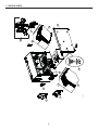 4
4
-
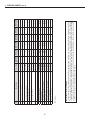 5
5
-
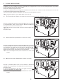 6
6
-
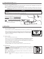 7
7
-
 8
8
-
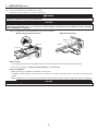 9
9
-
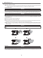 10
10
-
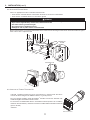 11
11
-
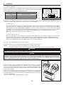 12
12
-
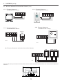 13
13
-
 14
14
-
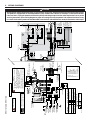 15
15
-
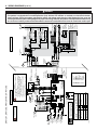 16
16
-
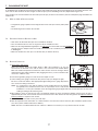 17
17
-
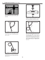 18
18
-
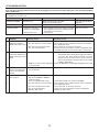 19
19
-
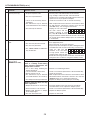 20
20
-
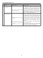 21
21
-
 22
22
-
 23
23
-
 24
24
-
 25
25
-
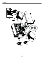 26
26
-
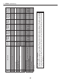 27
27
-
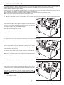 28
28
-
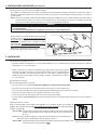 29
29
-
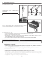 30
30
-
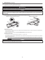 31
31
-
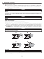 32
32
-
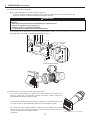 33
33
-
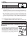 34
34
-
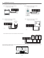 35
35
-
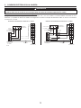 36
36
-
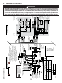 37
37
-
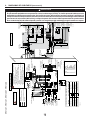 38
38
-
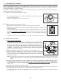 39
39
-
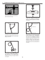 40
40
-
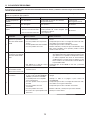 41
41
-
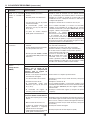 42
42
-
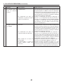 43
43
-
 44
44


Broan ERV110S Manual de usuario
- Tipo
- Manual de usuario
en otros idiomas
- English: Broan ERV110S User manual
Artículos relacionados
-
Broan ERV90HCS Manual de usuario
-
-
-
-
-
Broan ERVS100S Guía de instalación
-
NuTone Fresh Air System ERV90HCT Installation Instructions Manual
-
-
-
Broan ERV110S Guía del usuario