Jacuzzi Amiga Installation And Operating Instructions Manual
- Categoría
- Calentadores espaciales
- Tipo
- Installation And Operating Instructions Manual

BUILDER/COMFORT BATH SERIES
ELECTRONIC & MANUAL CONTROLS
INSTALLATION AND OPERATING INSTRUCTIONS
Installer: Leave this manual for homeowner.
Homeowner: Read this manual and keep for future reference.
©2005 Jacuzzi Whirlpool Bath K272000AF 7/06
Owner's Record
Save These Instructions for Future Use.
Date Purchased ____________________________________________________________
Purchased From ____________________________________________________________
Installed By ________________________________________________________________
Serial Number _____________________________________________________________
Model_____________________________________________________________________

ENGLISH
IMPORTANT SAFETY INSTRUCTIONS
READ AND FOLLOW ALL INSTRUCTIONS
SAVE THESE INSTRUCTIONS
INSTRUCTIONS PERTAINING TO A RISK OF FIRE, ELECTRIC
SHOCK, OR INJURY TO PERSONS
WARNING — WHEN USING THIS UNIT, BASIC PRECAUTIONS SHOULD ALWAYS BE FOLLOWED,
INCLUDING THE FOLLOWING:
DANGER — TO REDUCE THE RISK OF INJURY, DO NOT PERMIT CHILDREN TO USE THIS UNIT
UNLESS THEY ARE CLOSELY SUPERVISED AT ALL TIMES.
WARNING — USE THIS UNIT ONLY FOR ITS INTENDED USE AS DESCRIBED IN THIS MANUAL. DO
NOT USE ATTACHMENTS NOT RECOMMENDED BY THE MANUFACTURER.
WARNING — NEVER DROP OR INSERT ANY OBJECT INTO ANY OPENING.
WARNING — DO NOT OPERATE THIS UNIT WITHOUT THE GUARD OVER THE SUCTION FITTING.
WARNING — THIS UNIT MUST BE CONNECTED ONLY TO A SUPPLY CIRCUIT THAT IS PROTECTED
BY A GROUND FAULT CIRCUIT INTERRUPTER (GFCI). SUCH A GFCI SHOULD BE PROVIDED BY
THE INSTALLER AND SHOULD BE TESTED ON A ROUTINE BASIS. TO TEST THE GFCI, PUSH THE
TEST BUTTON. THE GFCI SHOULD INTERRUPT POWER. PUSH THE RESET BUTTON. POWER
SHOULD BE RESTORED. IF THE GFCI FAILS TO OPERATE IN THIS MANNER, THE GFCI IS
DEFECTIVE. IF THE GFCI INTERRUPTS POWER TO THE BATHTUB WITHOUT THE TEST BUTTON
BEING PUSHED, A GROUND CURRENT FLOWING, INDICATING A POSSIBILITY OF AN ELECTRIC
SHOCK. DO NOT USE THIS HYDROMASSAGE BATHTUB. DISCONNECT THE HYDROMASSAGE
BATHTUB AND HAVE THE PROBLEM CORRECTED BY A QUALIFIED SERVICE REPRESENTATIVE
BEFORE USING.
WARNING — (FOR PERMANENTLY CONNECTED UNITS) A GREEN COLORED TERMINAL (OR A WIRE
CONNECTOR MARKED “G”, “GR”, “GROUND”, OR “GROUNDING”) IS PROVIDED WITHIN THE TERMINAL
COMPARTMENT. TO REDUCE THE RISK OF ELECTRIC SHOCK, CONNECT THE TERMINAL OR
CONNECTOR TO THE GROUNDING TERMINAL OF YOUR ELECTRIC SERVICE OR SUPPLY PANEL WITH
A CONDUCTOR EQUIVALENT IN SIZE TO THE CIRCUIT CONDUCTORS SUPPLYING THIS EQUIPMENT.
OPERATING INSTRUCTIONS
WARNING — PROLONGED IMMERSION IN HOT WATER MAY INDUCE HYPERTHERMIA. HYPER-
THERMIA OCCURS WHEN THE INTERNAL TEMPERATURE OF THE BODY REACHES A LEVEL SEV-
ERAL DEGREES ABOVE THE NORMAL BODY TEMPERATURE OF 98.6°F. THE SYMPTOMS OF
HYPERTHERMIA INCLUDE AN INCREASE IN THE INTERNAL TEMPERATURE OF THE BODY, DIZZI-
NESS, LETHARGY, DROWSINESS AND FAINTING. THE EFFECTS OF HYPERTHERMIA INCLUDE:
A) FAILURE TO PERCEIVE HEAT
B) FAILURE TO RECOGNIZE THE NEED TO EXIT THE SPA OR HOT TUB,
C) UNAWARENESS OF IMPENDING HAZARD,
D) FETAL DAMAGE IN PREGNANT WOMEN,
E) PHYSICAL INABILITY TO EXIT THE SPA OR HOT TUB, AND
F) UNCONSCIOUSNESS RESULTING IN DANGER OF DROWNING.
WARNING — THE USE OF ALCOHOL, DRUGS OR MEDICATION CAN GREATLY INCREASE THE
RISK OF FATAL HYPERTHERMIA.
WARNING — DO NOT TAMPER WITH USER-OPERATED CONTROLS OR SUCH DEVICES.
2
Jacuzzi Whirlpool Bath K272000AF 7/06

ENGLISH
NOTE: This is a professional grade product. A knowledge of construction techniques, plumbing and electri-
cal installation according to codes are required for proper installation and user satisfaction. We recommend
that a licensed contractor perform the installation of all Jacuzzi Whirlpool Bath products. Our warranty does
not cover improper installation related problems.
PRODUCT SPECIFICATIONS ARE SUBJECT TO CHANGE WITHOUT NOTICE.
USE INSTALLATION INSTRUCTIONS SUPPLIED WITH PRODUCT.
The Company has obtained applicable code (standards) listings generally available on a national basis for products of this type.
It is the responsibility of the installer/owner to determine specific local code compliance prior to installation of the product. The
Company makes no representation or warranty regarding, and will not be responsible for any code compliance.
PRECAUTIONS
••
••
•Do not operate the hydromassage system unless the bath is filled with water to at least 1" to 2" (2,5 - 5,08 cm) above the
highest jet.
••
••
•Do not immerse the control panel by overfilling the bath.
••
••
•Do not use oil-based bath additives in your hydromassage bath.
••
••
•When cleaning your bath, do not use abrasive substances which will damage the bath's surface.
••
••
•To prevent discoloration of the acrylic finish, do not fill the bath with water in excess of 140°F (60°C).
WARNING — WHEN USING THIS UNIT, BASIC PRECAUTIONS SHOULD ALWAYS BE FOLLOWED,
INCLUDING THE FOLLOWING:
DANGER — RISK OF ELECTRIC SHOCK. CONNECT ONLY TO A CIRCUIT PROTECTED BY A GROUND
FAULT CIRCUIT INTERRUPTER (GFCI).
CAUTION — TEST THE GROUND FAULT CIRCUIT INTERRUPTER PROTECTING THIS APPLIANCE
PERIODICALLY IN ACCORDANCE WITH MANUFACTURER’S INSTRUCTIONS.
WARNING — USE THIS UNIT ONLY FOR ITS INTENDED USE AS DESCRIBED IN THIS MANUAL. DO NOT
USE ATTACHMENTS NOT RECOMMENDED BY THE MANUFACTURERS.
WARNING — TO AVOID INJURY, EXERCISE CAUTION WHEN ENTERING OR EXITING THE HYDROMASSAGE BATHTUB.
WARNING — KEEP BODY AND HAIR A MINIMUM OF 6" AWAY FROM SUCTION FITTING AT ALL TIMES
WHEN THE HYDROMASSAGE SYSTEM IS OPERATING. HAIR LONGER THAN SHOULDER LENGTH
SHOULD BE SECURED CLOSE TO THE HEAD.
WARNING — RISK OF ELECTRICAL SHOCK; DO NOT PERMIT ELECTRICAL APPLIANCES (SUCH AS HAIR DRYER,
LAMP, TELEPHONE, RADIO OR TELEVISION) WITHIN 60" (1.5 M) OF THIS HYDROMASSAGE BATHTUB.
WARNING — RISK OF ACCIDENTAL INJURY OR DROWNING; DO NOT USE DRUGS OR ALCOHOL
BEFORE OR DURING THE USE OF HYDROMASSAGE BATHTUB EQUIPPED WITH A HEATER TO AVOID
UNCONSCIOUSNESS AND POSSIBLE DROWNING.
WARNING — RISK OF FETAL INJURY; PREGNANT OR POSSIBLY PREGNANT WOMEN SHOULD
CONSULT A PHYSICIAN BEFORE USING A HYDROMASSAGE BATHTUB EQUIPPED WITH A HEATER.
WARNING — RISK OF HYPERTHERMIA AND POSSIBLE DROWNING; DO NOT USE A HYDROMASSAGE
BATHTUB EQUIPPED WITH A HEATER IMMEDIATELY FOLLOWING STRENUOUS EXERCISE.
WARNING — RISK OF HYPERTHERMIA AND POSSIBLE DROWNING; WATER TEMPERATURE IN EXCESS
OF 104°F (40°C) MAY BE INJURIOUS TO YOUR HEALTH. CHECK AND ADJUST WATER TEMPERATURE
BEFORE USE.
WARNING — RISK OF HYPERTHERMIA; PEOPLE USING MEDICATIONS AND/OR HAVING AN ADVERSE
MEDICAL HISTORY SHOULD CONSULT A PHYSICIAN BEFORE USING A HYDROMASSAGE BATHTUB
EQUIPPED WITH A HEATER.
FOR BUILT-IN AND DROP-IN UNITS, INSTALL TO PERMIT ACCESS FOR SERVICING.
THIS UNIT SHOULD BE ELECTRICALLY GROUNDED AND INSTALLED BY A LICENSED CONTRACTOR,
ELECTRICIAN, AND PLUMBER.
BUILDING MATERIALS AND WIRING SHOULD BE ROUTED AWAY FROM THE MOTOR/PUMP OR
BLOWER OR OTHER HEAT PRODUCING COMPONENTS OF THIS UNIT.
A PRESSURE WIRE CONNECTOR IS PROVIDED ON THE EXTERIOR OF THE MOTOR/PUMP AND
HEATER TO PERMIT CONNECTION OF AN NO. 8 AWG (8.4 MM) SOLID COPPER BONDING CONDUCTOR
BETWEEN THIS UNIT AND ALL OTHER ELECTRIC EQUIPMENT AND EXPOSED METAL IN THE VICINITY,
AS NEEDED TO COMPLY WITH LOCAL REQUIREMENTS.
INSTALLATION INSTRUCTIONS
3
Jacuzzi Whirlpool Bath K272000AF 7/06

ENGLISH
CONTENTS
Safety Instructions _____________________________________________________________________ 2-3
Contents _____________________________________________________________________________ 4
Specifications _________________________________________________________________________ 5-9
Roughing-in __________________________________________________________________________ 10-17
Cutout ______________________________________________________________________________ 17
Installation Instructions __________________________________________________________________ 18-24
Framing and Support _________________________________________________________________ 18
Skirts ______________________________________________________________________________ 19
Service Access _____________________________________________________________________ 20
Electrical Connections ________________________________________________________________ 21
Plumbing and Water Supply ___________________________________________________________ 22
Undermount Installation Instructions _____________________________________________________ 23-24
Operation ____________________________________________________________________________ 25-26
Maintenance __________________________________________________________________________ 27
General Troubleshooting Guide ___________________________________________________________ 28
Authorized Service _____________________________________________________________________ 30
Warranty _____________________________________________________________________________ 31-32
NOTE: If you need a referral for a service company near you, or need assistance with operation or maintenance
related questions, please call our USA Service Support Department at 1-800-288-4002. Visit our web site at http:/
/www.jacuzzi.com/ for products and services.
To find service agent listings for:
Electrical or Mechanical Repairs visit http://jacuzzi.com/pdf/ASA.PDF
Finish, Surface, or Shell-Related Repairs visit http://jacuzzi.com/pdf/AFC.PDF
Repair Parts or Accessories visit http://jacuzzi.com/pdf/MPD.PDF
4
Jacuzzi Whirlpool Bath K272000AF 7/06

ENGLISH
Important: Read complete instructions before beginning installation.
Each whirlpool bath arrives ready for installation, completely equipped with motor/pump assembly and plumbing and fittings
necessary for whirlpool operation. An optional drain/overflow kit is available for installation on the bath.
Remove the bath from the carton. Retain the shipping carton until satisfactory inspection of the product has been made. Do
not lift the bath by the plumbing at any time; handle by the shell only.
Immediately upon receipt, inspect the shell before installing. Should inspection reveal any damage or defect in the finish, do
not install the bath. Damage or defect to the finish claimed after the bath is installed is excluded from the warranty. Jacuzzi
Whirlpool Bath responsibility for shipping damage ceases upon delivery of the products in good order to the carrier. Refer any
claims for damage to the carrier. For definitions of warranty coverage and limitations, refer to the published warranty informa-
tion packed with the product.
All bath units are factory tested for proper operation and watertight connections prior to shipping. NOTE: Prior to installa-
tion, the bath must be filled with water and operated to check for leaks that may have resulted from shipping damage
or mishandling. Jacuzzi Whirlpool Bath is not responsible for any defect that could have been discovered, repaired, or
avoided by following this inspection and testing procedure.
Not all tubs shown may be available as export units. Export tubs come with MANUAL controls and may come:
• with Pump/motor packaged separately,
• with Pump/motor installed,
• with NO overflow cutout.
Because of the variety of export tub types some instructions may not apply to your unit. Disregard instructions that do not
apply to your specific tub.
BATHS WITHOUT INTEGRAL SKIRT
END VIEW
H
W
SIDE VIEW
L
2"
(51 mm)
BATHS WITH 3-SIDED TILE FLANGE
L
1"
(25 mm)
H
W
SIDE VIEW END VIEW
L
1"
(25 mm)
H
W
SIDE VIEW
BATHS WITH INTEGRAL SKIRT
END VIEW
SPECIFICATIONS (Rectangular) LH = Left Hand, RH = Right Hand
MODEL
PRODUCT
WEIGHT
OPERATING
GALLONAGE
TOTAL WEIGHT/
FLOOR LOADING
DIMENSIONS
DRAIN/OVERFLOW
DIMENSIONS SKIRT &
MOUNTING
CUTOUT
HEATER READY
FOR FIELD
INSTALLATION
AMIGA™
LH & RH
72" (1829 mm) L*
36" ( 914 mm) W
20-3/4" ( 533 mm) H
772 lb
(351 kg)/
43 lb/ft2
(210 kg/m2)
50 U.S. gal
(186 liters)
105 lb
(48 kg)
16-7/8" (429 mm) A
14" (356 mm) B
Optional,
U-Frame
70" x 34"
(1778 mm x
864 mm)
NOTE: The overall dimensions are nominal with a tolerance of +0 and -1/4" (6,4 mm).
FOR ALL UNITS: Electrical Service Requirements: All require a dedicated GFCI protected separate circuit.
(Optional) RapidHeatTM: 115 VAC, 15 AMP, 60 Hz. dedicated GFCI protected separate circuit.
Motor/Pump: 115 VAC, 15 Amp, 60 Hz. dedicated GFCI protected separate circuit.
*Add 1/4" (6,4 mm) to this dimension when roughing-in for 3-wall niche.
BIANCA©
LH
72" (1829 mm) L*
48" (1219 mm) W
20-1/2" ( 521 mm) H
993 lb
(451 kg)/
41 lb/ft2
(200 kg/m2)
73 U.S. gal
(276 liters) 135 lb
(61 kg)
16" (406 mm) A
8-1/2" (216 mm) B Optional,
U-Frame
70" x 46"
(1778 mm x
1168 mm)
AMIGA™
WITH INTEGRAL
SKIRT
LH & RH
72" (1829 mm) L*
36" ( 914 mm) W
20-3/4" ( 533 mm) H
796 lb
(362 kg)/
44 lb/ft2
(214 kg/m2)
50 U.S. gal
(186 liters)
129 lb
(59 kg)
16-7/8" (429 mm) A
14" (356 mm) B
Integral
NA
CETRA©
WITH INTEGRAL
SKIRT
LH & RH
60" (1524 mm) L*
32" ( 813 mm) W
20-1/2" ( 521 mm) H
727 lb
(330 kg)/
55 lb/ft2
(268 kg/m2)
46 U.S. gal
(174 liters)
94 lb
(43 kg)
17-7/8" (454 mm) A
9-3/8" (238 mm) B
Integral
NA
CETRA© 536
LH & RH
60" (1524 mm) L*
36" ( 914 mm) W
21-1/4" ( 553 mm) H
742 lb
(337 kg)/
50 lb/ft2
(244 kg/m2)
48 U.S. gal
(181 liters)
92 lb
(42 kg)
Optional
U-Frame
58" x 34-1/4"
(1473 mm x
870 mm)
18-1/2" ( 470 mm) A
9" ( 229 mm) B
CETRA© 532
LH & RH
60" (1524 mm) L*
31-7/8" ( 791 mm) W
21-1/4" ( 553 mm) H
697 lb
(317 kg)/
53 lb/ft2
(259 kg/m2)
43 U.S. gal
(163 liters)
89 lb
(41 kg)
Optional
U-Frame
58" x 30-1/4"
(1473 mm x
768 mm)
18-1/2" ( 470 mm) A
9" ( 229 mm) B
RECTANGULAR BATHS
SPECIFICATIONS
Yes
(S750000 HEATER KIT)
Yes
(S750000 HEATER KIT)
Yes
(S750000 HEATER KIT)
Yes
(S750000 HEATER KIT)
Yes
(S750000 HEATER KIT)
Yes
(S750000 HEATER KIT)
5
Jacuzzi Whirlpool Bath K272000AF 7/06
DRAIN/OVERFLOW
A
B

ENGLISH
6
Jacuzzi Whirlpool Bath K272000AF 7/06
SPECIFICATIONS (Rectangular) LH = Left Hand, RH = Right Hand
MODEL PRODUCT
WEIGHT
OPERATING
GALLONAGE
TOTAL WEIGHT/
FLOOR LOADING
DIMENSIONS DRAIN/OVERFLOW
DIMENSIONS
SKIRT &
MOUNTING
CUTOUT
HEATER READY
FOR FIELD
INSTALLATION
*Add 1/4" (6,4 mm) to this dimension when roughing-in for 3-wall niche.
60" (1524 mm) L*
30" ( 762 mm) W
20-1/4" ( 483 mm) H
662 lb
(301 kg)/
53 lb/ft2
(259 kg/m2)
38 U.S. gal
(144 liters)
95 lb
(43 kg)
16-3/4" (425 mm) A
9-1/4" (235 mm) B
Integral
NALUXURA™ 530
WITH INTEGRAL
SKIRT
LH & RH
LUXURA™ 5
WITH INTEGRAL
3-SIDED TILE
FLANGE
LH & RH
60" (1524 mm) L*
32" ( 813 mm) W
20-1/4" ( 514 mm) H
697 lb
(264 kg)/
52 lb/ft2
(254 kg/m2)
44 U.S. gal
(167 liters)
80 lb
(36 kg)
15-1/4" (387 mm) A
8-1/4" (210 mm) B
Optional,
U-Frame
NA
Molded-in
Tile Flange
LUXURA™ 5
WITH INTEGRAL
SKIRT
LH & RH
60" (1524 mm) L
32" ( 813 mm) W
20-1/4" ( 514 mm) H
700 lb
(318 kg)/
53 lb/ft2
(259 kg/m2)
42 U.S. gal
(159 liters)
100 lb
(45 kg)
15-1/4" (387 mm) A
8-1/4" (210 mm) B
Integral
LUXURA™ 5.5
LH & RH
66" (1676 mm) L*
34" ( 864 mm) W
20" ( 508 mm) H
823 lb
(374 kg)/
53 lb/ft2
(259 kg/m2)
58 U.S. gal
(220 liters)
90 lb
(41 kg)
15-1/4" (387 mm) A
8-3/8" (213 mm) B
Optional,
U-Frame
64" x 32"
(1626 mm x
813 mm)
CETRA© 536
WITH INTEGRAL
SKIRT
LH & RH
60" (1524 mm) L*
36" ( 914 mm) W
21-1/4" ( 553 mm) H
742 lb
(337 kg)/
50 lb/ft2
(244 kg/m2)
48 U.S. gal
(181 liters)
92 lb
(42 kg)
IntegralNA
18-1/2" ( 470 mm) A
9" ( 229 mm) B
MAJORA© 5
LH & RH
60" (1524 mm) L*
42" (1067 mm) W
19-1/2" ( 495 mm) H
728 lb
(331 kg)/
42 lb/ft2
(205 kg/m2)
46 U.S. gal
(172 liters)
95 lb
(43 kg)
15" (381 mm) A
8-3/4" (222 mm) B
Not
Available
58" x 40"
(1473 mm x
1016 mm)
MAJORA© 6
LH & RH
72" (1829 mm) L*
42" (1067 mm) W
19-3/4" ( 502 mm) H
937 lb
(423 kg)/
44 lb/ft2
(215 kg/m2)
70 U.S. gal
(265 liters)
104 lb
(47 kg)
15-5/8" (397 mm) A
10-1/2" (267 mm) B
Not
Available
70" x 40"
(1778 mm x
1016 mm)
MAJORA© 6
WITH INTEGRAL
SKIRT
LH & RH
72" (1829 mm) L*
42" (1067 mm) W
19-3/4" ( 502 mm) H
947 lb
(430 kg)/
45 lb/ft2
(220 kg/m2)
70 U.S. gal
(265 liters)
114 lb
(52 kg)
15-5/8" (397 mm) A
10-1/2" (267 mm) B
Integral
NA
MITO© 5
LH & RH
60" (1524 mm) L*
42" (1067 mm) W
21" ( 533 mm) H
866 lb
(394 kg)/
50 lb/ft2
(244 kg/m2)
62 U.S. gal
(235 liters)
100 lb
(45 kg)
17-1/2" (445 mm) A
11-7/8" (302 mm) B
Optional,
U-Frame
58" x 40"
(1473 mm x
1016 mm)
72" (1829 mm) L*
42" (1067 mm) W
21-1/2" ( 546 mm) H
993 lb
(451 kg)/
47 lb/ft2
(229 kg/m2)
76 U.S. gal
(288 liters)
110 lb
(50 kg)
MITO© 6
LH & RH
17-1/2" (445 mm) A
11-7/8" (302 mm) B 70" x 40"
(1778 mm x
1016 mm)
60" (1524 mm) L*
42" (1067 mm) W
18-1/2" ( 470 mm) H
722 lb
(328 kg)/
41 lb/ft2
(200 kg/m2)
46 U.S. gal
(170 liters)
97 lb
(44 kg)
NOVA© 5
LH & RH
14-3/4" (375 mm) A
8-1/2" (216 mm) B
Optional,
U-Frame
58" x 40"
(1473 mm x
1016 mm)
Not
Available
Yes
(S750000 HEATER KIT)
Yes
(S750000 HEATER KIT)
Yes
(S750000 HEATER KIT)
Yes
(S750000 HEATER KIT)
Yes
(S750000 HEATER KIT)
Yes
(S750000 HEATER KIT)
Yes
(S750000 HEATER KIT)
Yes
(S750000 HEATER KIT)
Yes
(S750000 HEATER KIT)
Yes
(S750000 HEATER KIT)
Yes
(U395000 HEATER KIT)
NA
NOTE: The overall dimensions are nominal with a tolerance of +0 and -1/4" (6,4 mm).
FOR ALL UNITS: Electrical Service Requirements: All require a dedicated GFCI protected separate circuit.
(Optional) RapidHeatTM: 115 VAC, 15 AMP, 60 Hz. dedicated GFCI protected separate circuit.
Motor/Pump: 115 VAC, 15 Amp, 60 Hz. dedicated GFCI protected separate circuit.
SPECIFICATIONS

ENGLISH
SPECIFICATIONS (Rectangular) LH = Left Hand, RH = Right Hand
MODEL
PRODUCT
WEIGHT
OPERATING
GALLONAGE
TOTAL WEIGHT/
FLOOR LOADING
DIMENSIONS
DRAIN/OVERFLOW
DIMENSIONS
SKIRT &
MOUNTING
CUTOUT
HEATER READY
FOR FIELD
INSTALLATION
*Add 1/4" (6,4 mm) to this dimension when roughing-in for 3-wall niche.
15-7/8" (403 mm) A
9-1/4" (235 mm) B
NOVA© 5
WITH INTEGRAL
SKIRT
LH & RH
60" (1524 mm) L*
42" (1067 mm) W
18-1/2" ( 470 mm) H
737 lb
(335 kg)/
42 lb/ft2
(205 kg/m2)
45 U.S. gal
(174 liters)
112 lb
(51 kg) Integral
NA
NOVA© 6
LH & RH
72" (1829 mm) L*
42" (1067 mm) W
20-1/2" ( 521 mm) H
876 lb
(398 kg)/
42 lb/ft2
(205 kg/m2)
62 U.S. gal
(235 liters)
110 lb
(50 kg)
14-3/4" (375 mm) A
8-1/2" (216 mm) B Optional,
U-Frame
70" x 40"
(1778 mm x
1016 mm)
NOVA© 536
WITH INTEGRAL
SKIRT
LH & RH
60" (1524 mm) L*
36" ( 914 mm) W
19-1/4" ( 489 mm) H
698 lb
(317 kg)/
47 lb/ft2
(229 kg/m2)
42 U.S. gal
(159 liters) 98 lb
(45 kg)
15-1/8" (384 mm) A
9" (229 mm) B
14-5/8" (372 mm) A
9" (229 mm) B
Not
Available
Integral
683 lb
(310 kg)/
46 lb/ft2
(224 kg/m2)
58" x 34"
(1473 mm x
863 mm)
NA
NOVA© 536
LH & RH
60" (1524 mm) L*
36" ( 914 mm) W
19-1/4" ( 489 mm) H
42 U.S. gal
(159 liters)
83 lb
(38 kg)
60" (1524 mm) L*
42" (1067 mm) W
18-1/2" ( 470 mm) H
722 lb
(328 kg)/
41 lb/ft2
(200 kg/m2)
46 U.S. gal
(174 liters)
97 lb
(44 kg)
NOVA© 5
WITH INTEGRAL
3-SIDED TILE
FLANGE
LH & RH
14-3/4" (375 mm) A
8-1/2" (216 mm) B
Not
Available
SIGNA© 5
LH & RH
60" (1524 mm) L*
42" (1067 mm) W
22" ( 559 mm) H
708 lb
(321 kg)/
40 lb/ft2
(195 kg/m2)
42 U.S. gal
(159 liters)
108 lb
(49 kg)
17-1/2" (445 mm) A
12-1/2" (318 mm) B
Optional,
U-Frame
58" x 40"
(1473 mm x
1016 mm)
NOVA© 636
WITH INTEGRAL
SKIRT
LH & RH
72" (1829 mm) L*
36" ( 914 mm) W
19" ( 483 mm) H
824 lb
(375 kg)/
45.8 lb/ft2
(223 kg/m2)
56 U.S. gal
(223 liters)
108 lb
(49 kg)
14-5/8" (372 mm) A
9-3/8" (238 mm) B Integral
NA
SIGNA© 5
WITH INTEGRAL
3-SIDED TILE
FLANGE
RH
60" (1524 mm) L*
42" (1067 mm) W
22" ( 559 mm) H
708 lb
(321 kg)/
40 lb/ft2
(195 kg/m2)
42 U.S. gal
(159 liters)
108 lb
(49 kg)
17-1/2" (445 mm) A
12-1/2" (318 mm) B
Optional,
U-Frame
NA
SIGNA© 6
LH & RH
72" (1829 mm) L*
42" (1067 mm) W
22" ( 559 mm) H
826 lb
(375 kg)/
39 lb/ft2
(190 kg/m2)
55 U.S. gal
(208 liters)
118 lb
(54 kg)
16-7/8" (429 mm) A
14" (356 mm) B Not
Available
70" x 40"
(1778 mm x
1016 mm)
No
Yes
(S750000 HEATER KIT)
Yes
(S750000 HEATER KIT)
Yes
(S750000 HEATER KIT)
Yes
(S750000 HEATER KIT)
Yes
(S750000 HEATER KIT)
Yes
(S750000 HEATER KIT)
SIGNA© 5 WITH
INTEGRAL SKIRT,
FRONT RIGHT
MOTOR/PUMP
LH & RH
60" (1524 mm) L*
42" (1067 mm) W
22" ( 559 mm) H
723 lb
(329 kg)/
41 lb/ft2
(200 kg/m2)
42 U.S. gal
(159 liters)
123 lb
(56 kg)
17-7/8" (451 mm) A
12-3/4" (330 mm) B
Integral
NA Yes
(U395000 HEATER KIT)
NOTE: The overall dimensions are nominal with a tolerance of +0 and -1/4" (6,4 mm).
FOR ALL UNITS: Electrical Service Requirements: All require a dedicated GFCI protected separate circuit.
(Optional) RapidHeatTM: 115 VAC, 15 AMP, 60 Hz. dedicated GFCI protected separate circuit.
Motor/Pump: 115 VAC, 15 Amp, 60 Hz. dedicated GFCI protected separate circuit.
7
Jacuzzi Whirlpool Bath K272000AF 7/06
NA
Molded-in
Tile Flange
SPECIFICATIONS
Yes
(S750000 HEATER KIT)
Yes
(S750000 HEATER KIT)

ENGLISH
RIMLESS OVAL BATHS
SIDE VIEW END VIEW
L
H
7-1/2"
(191 mm)
W
2"
(51 mm)
FRESCO
3-1/2"
(89 mm) 8"
(203 mm)
L
W
H
2'' (51 mm)
MILANO
SIDE VIEW END VIEW
RIVA 5 & RIVA 6
GALLERY 5 OVAL & GALLERY 6 OVAL
SIDE VIEW
W
H2''
(51 mm)
L
END VIEW
DRAIN/OVERFLOW
A
B
FRESCO©
LH & RH
71-1/2" (1816 mm) L
42" (1067 mm) W
27-1/4" ( 692 mm) H*
921 lb
(419 kg)/
44 lb/ft2
(220 kg/m2)
63 U.S. gal
(239 liters)
146 lb
(66 kg)
72" (1829 mm) L
42" (1067 mm) W
20-1/2" ( 521 mm) H
871 lb
(396 kg)/
42 lb/ft2
(205 kg/m2)
62 U.S. gal
(235 liters)
105 lb
(48 kg)
20-1/8" (511 mm) A
11-3/4" (299 mm) B
16" (406 mm) A
11-1/2" (292 mm) B
RIVA© 6
LH & RH
Not
Available
Not
Available
Template
Provided
P/N
P188000
Template
Provided
P/N
P186000
MODEL
PRODUCT
WEIGHT
OPERATING
GALLONAGE
TOTAL WEIGHT/
FLOOR LOADING
SPECIFICATIONS (Oval) LH = Left Hand, RH = Right Hand
DIMENSIONS
DRAIN/OVERFLOW
DIMENSIONS
SKIRT &
MOUNTING
CUTOUT
HEATER READY
FOR FIELD
INSTALLATION
GALLERY™ 5
OVAL
LH & RH
62" (1575 mm) L
43" (1092 mm) W
19" ( 483 mm) H
746 lb
(339 kg)/
40 lb/ft2
(195 kg/m2)
48 U.S. gal
(182 liters)
96 lb
(44 kg)
14-3/4" (375 mm) A
9-1/2" (241 mm) B
Not
Available
Template
Provided
P/N
P186000
871 lb
(395 kg)/
42 lb/ft2
(205 kg/m2)
62 U.S. gal
(235 liters)
105 lb
(48 kg)
16" (406 mm) A
11-1/2" (292 mm) B
GALLERY™ 6
OVAL
LH & RH
Not
Available
Template
Provided
P/N
P186000
72" (1829 mm) L
42" (1067 mm) W
20-1/2" ( 521 mm) H
Template
Provided
P/N
P188000
MILANO™
LH & RH
72" (1829 mm) L
40" (1016 mm) W
20-3/4" ( 527 mm) H
893 lb
(406 kg)/
45 lb/ft2
(220 kg/m2)
60 U.S. gal
(227 liters)
143 lb
(65 kg)
18-1/2" (470 mm) A
11" (279 mm) B
Not
Available
RIVA© 5
LH & RH
62" (1575 mm) L
43" (1092 mm) W
19" ( 483 mm) H
746 lb
(339 kg)/
40 lb/ft2
(195 kg/m2)
48 U.S. gal
(182 liters)
96 lb
(44 kg)
14-3/4" (375 mm) A
9-1/2" (241 mm) B
Not
Available
Template
Provided
P/N
P186000
Yes
(S750000 HEATER KIT)
Yes
(S750000 HEATER KIT)
Yes
(S750000 HEATER KIT)
Yes
(S750000 HEATER KIT)
Yes
(S750000 HEATER KIT)
Yes
(S750000 HEATER KIT)
Not
Available
Yes
(S750000 HEATER KIT)
72" (1829 mm) L
42" (1067 mm) W
23" ( 584 mm) H
1221 lb
(555 kg)/
58 lb/ft2
(283 kg/m2)
96 U.S. gal
(364 liters)
121 lb
(55 kg)
19-1/8" (486 mm) A
11" (279 mm) B
Template
Provided
P/N
P819000
LUNA™
RH
END VIEW
H
W
SIDE VIEW
L
2"
(51 mm)
LUNA
OPALIA™
LH & RH
72" (1829 mm) L
44" (1118 mm) W
22-1/4" ( 565 mm) H
978 lb
(445 kg)/
45 lb/ft2
(220 kg/m2)
70 U.S. gal
(265 liters)
145 lb
(66 kg)
18-3/4" (476 mm) A
12" (305 mm) B
Template
Provided
P/N
P186000
Not
Available
Yes
(S750000 HEATER KIT)
871 lb
(395 kg)/
42 lb/ft2
(205 kg/m2)
62 U.S. gal
(235 liters)
105 lb
(48 kg)
16" (406 mm) A
11-1/2" (292 mm) B
GALLERY™ 6
OVAL
UNDERMOUNT
LH & RH
Not
Available
Template
Provided
P/N
X302000
72" (1829 mm) L
42" (1067 mm) W
20-1/2" ( 521 mm) H
Yes
(S750000 HEATER KIT)
NOTE: The overall dimensions are nominal with a tolerance of +0 and -1/4" (6,4 mm).
FOR ALL UNITS: Electrical Service Requirements: All require a dedicated GFCI protected separate circuit.
(Optional) RapidHeatTM: 115 VAC, 15 AMP, 60 Hz. dedicated GFCI protected separate circuit.
Motor/Pump: 115 VAC, 15 Amp, 60 Hz. dedicated GFCI protected separate circuit.
8
Jacuzzi Whirlpool Bath K272000AF 7/06
* For Fresco™ models H551, H549, and H550 this height is 23-3/4"
SPECIFICATIONS

ENGLISH
MODEL
PRODUCT
WEIGHT
OPERATING
GALLONAGE
TOTAL WEIGHT/
FLOOR LOADING
SPECIFICATIONS (Corner) LH = Left Hand, RH = Right Hand
DIMENSIONS
DRAIN/OVERFLOW
DIMENSIONS
SKIRT &
MOUNTING
CUTOUT
HEATER READY
FOR FIELD
INSTALLATION
60" (1524 mm) L
60" (1524 mm) L
20-3/4" ( 527 mm) H
984 lb
(447 kg)/
39 lb/ft2
(190 kg/m2)
74 U.S. gal
(280 liters)
118 lb
(54 kg)
TARA™
LH & RH
16" (406 mm) A
12-3/8" (314 mm) B
Optional
See
Page 17
60" (1524 mm) L
60" (1524 mm) L
20-3/4" ( 527 mm) H
999 lb
(454 kg)/
40 lb/ft2
(195 kg/m2)
74 U.S. gal
(280 liters)
133 lb
(61 kg)
TARA™
WITH INTEGRAL
SKIRT RH
16" (406 mm) A
12-3/8" (314 mm) B
Integral
NA No
CAPELLA© 60
WITH INTEGRAL
SKIRT RH
60" (1524 mm) L
60" (1524 mm) L
20-1/2" ( 521 mm) H
880 lb
(400 kg)/
35 lb/ft2
(171 kg/m2)
60 U.S. gal
(227 liters)
130 lb
(59 kg)
18" (457 mm) A
12-1/8" (308 mm) B Integral
NA No
CAPELLA© 60
LH & RH
60" (1524 mm) L
60" (1524 mm) L
20-1/2" ( 521 mm) H
870 lb
(395 kg)/
35 lb/ft2
(171 kg/m2)
60 U.S. gal
(227 liters)
120 lb
(54 kg)
18" (457 mm) A
12-1/8" (308 mm) B Not
Available
See
Page 17 No
CAPELLA© 55
WITH INTEGRAL
SKIRT RH
55" (1397 mm) L
55" (1397 mm) L
20-1/2" ( 521 mm) H
1025 lb
(466 kg)/
48.8 lb/ft2
(238 kg/m2)
54 U.S. gal
(204 liters)
125 lb
(57 kg)
18" (457 mm) A
12-1/8" (308 mm) B Integral
NA No
60" (1524 mm) L
60" (1524 mm) L
22-1/2" ( 572 mm) H
984 lb
(447 kg)/
39 lb/ft2
(244 kg/m2)
74 U.S. gal
(280 liters)
118 lb
(54 kg)
GALLERY™
CORNER
LH & RH
18-1/8" (451 mm) A
12" (305 mm) B
See
Page 17
Not
Available
CAPELLA© 55
RH
55" (1397 mm) L
55" (1397 mm) L
20-1/4" ( 514 mm) H
791 lb
(360 kg)/
38 lb/ft2
(185 kg/m2)
51 U.S. gal
(193 liters)
116 lb
(53 kg)
17-1/2" (445 mm) A
9-5/8" (245 mm) B
Optional
Template
Provided
P/N
DA24000
CAPELLA©
SPACESAVER
WITH INTEGRAL
SKIRT RH
60" (1524 mm) L
60" (1524 mm) L
20-1/2" ( 521 mm) H
880 lb
(400 kg)/
35 lb/ft2
(171 kg/m2)
60 U.S. gal
(227 liters)
130 lb
(59 kg)
18" (457 mm) A
12-3/8" (308 mm) B Integral No
CAPELLA 55, CAPELLA 60, & TARA WITH INTEGRAL SKIRT
1"
(25 mm) H
FRONT VIEW SIDE VIEW
CAPELLA SPACESAVER WITH INTEGRAL SKIRT
1"
(25 mm)
H
FRONT VIEW SIDE VIEW
NA
DRAIN/OVERFLOW
A
B
H
2"
(51 mm)
SIDE VIEW END VIEW
CORNER BATH
Yes
(S750000 HEATER KIT)
Yes
(S750000 HEATER KIT)
Yes
(S750000 HEATER KIT)
CORNER BATHS
60" (1524 mm) L
60" (1524 mm) L
20-1/2" ( 521 mm) H
870 lb
(395 kg)/
35 lb/ft2
(171 kg/m2)
60 U.S. gal
(227 liters)
120 lb
(54 kg)
18" (457 mm) A
12-1/8" (308 mm) B Not
Available
See
Page 17 No
CAPELLA© 60
FRONT LEFT
MOTOR/PUMP
LH
NOTE: The overall dimensions are nominal with a tolerance of +0 and -1/4" (6,4 mm).
FOR ALL UNITS: Electrical Service Requirements: All require a dedicated GFCI protected separate circuit.
(Optional) RapidHeatTM: 115 VAC, 15 AMP, 60 Hz. dedicated GFCI protected separate circuit.
Motor/Pump: 115 VAC, 15 Amp, 60 Hz. dedicated GFCI protected separate circuit.
9
Jacuzzi Whirlpool Bath K272000AF 7/06
SPECIFICATIONS

ENGLISH
ROUGHING-IN REFERENCE (RECTANGULAR)
AMIGA™, Left Hand
*72''
18''
36''
2''
16'' x 4''
14''
12" H x 18" L
Service Access
11-1/8''
Motor
Opt. Service Access
10
Jacuzzi Whirlpool Bath K272000AF 7/06
*72''
18''
36''
2''
16'' x 4''
14''
Motor
12" H x 18" L
Service Access
Opt. Service Access
11-1/8''
AMIGA™, Right Hand
14-1/2"
AMIGA™ WITH INTEGRAL SKIRT,
Left Hand
*72''
36''
2''
16'' x 4''
11-1/8''
Motor
17-3/8"
*72''
36''
2''
16'' x 4''
14-1/2''
Motor
11-1/8''
AMIGA™ WITH INTEGRAL SKIRT,
Right Hand
17-3/8''
BIANCA™
*72"
24"
48"
8-1/2"
13-3/4"
13-1/2" x 4"
(Left-hand only as shown)
2"
Motor
12" H x 18" L
Service Access
Opt. Service Access
*60"
32"
CETRA™ W/INTEGRAL SKIRT, Left Hand
15-5/8"
2"
10" x 4"
9-3/8"
5-11/16"
Motor
CETRA™ W/INTEGRAL SKIRT, Right Hand
*60"
32"
15-5/8"
2"
10" x 4"
9-3/8" 5-11/16"
Motor
9" CETRA™ 532, Left Hand
*60"
32"
16"
12" x 4"
Motor
2"
5-3/4"
12" H x 18" L
Service Access
Opt. Service Access
9"
CETRA™ 532, Right Hand
12" x 4"
Motor
2" 5-3/4"
12" H x 18" L
Service Access
Opt. Service Access
*60"
32"
16"
9"
CETRA™ 536, Left Hand
*60"
36"
18"
12" x 4"
Motor
12" H x 18" L
Service Access
Opt. Service Access
2"
5-3/4"
9"
CETRA™ 536, Right Hand
12" x 4"
Motor
12" H x 18" L
Service Access
Opt. Service Access
2" 5-3/4"
*60"
36"
18"
9"
CETRA™ 536 WITH INTEGRAL SKIRT, Left Hand
*60"
36"
17-3/8" 12" x 4"
2"5-3/4"
Motor
9"
CETRA™ 536 WITH INTEGRAL SKIRT, Right Hand
12" x 4"
2" 5-3/4"
Motor
*60"
36"
17-3/8"
2-1/2"
*60"
16"
32"
12" x 5"
8-1/4"
LUXURA™ 5, Left Hand
Motor
12" H x 18" L
Service Access
Opt. Service Access
2-1/2"
5-1/4"
LUXURA™ 5, Right Hand
2-1/2"
15" x 5"
8-1/4"
Motor
12" H x 18" L
Service Access
Opt. Service Access
2-1/2" 5-1/4"
*60"
16"
32
"
ROUGHING-IN
*Add 1/4" (6,4 mm) to this dimension when roughing-in for 3-wall niche.
NOTE: 1. The overall dimensions are nominal with a tolerance of +0 and -1/4" (6,4 mm).
2. Service Access dimensions given are minimum. Service access is still required for units that do not have pre-installed Pump/Motor.
3. Measurements inside each unit represent cutout in floor to allow for drain/overflow.
4. All measurements are in inches. To convert to millimeters, multiply inches by 25.4.
5. Not all export units come with pre-installed Pump/Motor.

ENGLISH
MITO™ 5, Left Hand
30"
42"
*60"
10" x 4"
2"
11-7/8
"
Motor
12" H x 18" L
Service Access
Opt. Service
Access
5-3/8"
MITO™ 5, Right Hand
30"
42"
*60"
10" x 4"
2"
11-7/8"
Motor
12" H x 18" L
Service Acces
s
O
pt.
S
ervice
Access
5-3/8"
ROUGHING-IN REFERENCE (RECTANGULAR)
11
Jacuzzi Whirlpool Bath K272000AF 7/06
LUXURA™ 5 WITH INTEGRAL SKIRT, Left Hand
2-1/2"
12" x 5"
8-1/4"
Motor
2-1/2"
5-1/4"
*60"
15-3/8"
32"
LUXURA™ 5 WITH INTEGRAL SKIRT, Right Hand
2-1/2"
12" x 5"
8-1/4"
Motor
2-1/2" 5-1/4"
*60"
15-3/8"
32"
12" x 5"
2-1/2"
*66"
17"
34"
8-3/8"
LUXURA™ 5.5, Left Hand
Motor
12" H x 18" L
Service Access
Opt. Service Access
2-1/2"
5-3/8"
LUXURA™ 5.5, Right Hand
12" x 5"
2-1/2"
*66"
17"
34"
8-3/8"
Motor
12" H x 18" L
Service Access
Opt. Service Access
2-1/2" 5-3/8"
2-1/2"
*60"
14-3/8"
30"
12" x 5"
9-1/4"
LUXURA™ 530 WITH INTEGRAL SKIRT, Left Hand
Motor
2-1/2"
5-7/8"
LUXURA™ 530 WITH INTEGRAL SKIRT, Right Hand
2-1/2"
*60"
14-3/8"
30"
12" x 5"
9-1/4"
Motor
2-1/2" 5-7/8"
MAJORA™ 5, Left Hand
42"
*60"
21"
8-3/4"
10" x 4"
2"
Motor
12" H x 18" L
Service Access
Opt. Service Access
4-3/8"
MAJORA™ 5, Right Hand
42"
*60"
21"
8-3/4"
10" x 4"
2"
Motor
12" H x 18" L
Service Access
Opt. Service Access 4-3/8"
MAJORA™ 6, Left Hand
42"
*72"
12" x 4"
21"
2"
10-1/2"
Motor
12" H x 18" L
Service Access
Opt. Service Access
4-3/8"
MAJORA™ 6, Right Hand
42"
*72"
12" x 4" 21"
2" 10-1/2"
Motor
12" H x 18" L
Service Access
Opt. Service Access
4-3/8"
MAJORA™ 6 W/INTEGRAL SKIRT, Left Hand
42"
*72"
12" x 4"
20-1/2"
2"
8-1/2"
Motor
4-3/8"
MAJORA™ 6 W/INTEGRAL SKIRT, Right Hand
42"
*72"
12" x 4" 20-1/2"
2"
8-1/2"
Motor
4-3/8"
MITO™ 6, Left Hand
36"
42"
*72"
11-7/8"
10" x 4"
2"
Motor
12" H x 18" L
Service Access
Opt. Service
Access
5-3/8"
ROUGHING-IN
*Add 1/4" (6,4 mm) to this dimension when roughing-in for 3-wall niche.
NOTE: 1. The overall dimensions are nominal with a tolerance of +0 and -1/4" (6,4 mm).
2. Service Access dimensions given are minimum. Service access is still required for units that do not have pre-installed Pump/Motor.
3. Measurements inside each unit represent cutout in floor to allow for drain/overflow.
4. All measurements are in inches. To convert to millimeters, multiply inches by 25.4.
5. Not all export units come with pre-installed Pump/Motor.

ENGLISH
ROUGHING-IN REFERENCE (RECTANGULAR)
12
Jacuzzi Whirlpool Bath K272000AF 7/06
36"
42"
*72"
11-7/8"
MITO™ 6, Right Hand
10" x 4"
2"
Motor
12" H x 18" L
Service Access
Opt. Service
Access
5-3/8"
NOVA™ 5, Left Hand
*60"
21"
42"
11" x 4"
Motor
12
"
H x 18
"
L
Service Acces
s
Opt. Service Access
2''
8-1/2''
5-3/8''
NOVA™ 5, Right Hand
*60"
21"
42"
11" x 4"
Motor
12" H x 18" L
Service Access
Opt. Service Access 2'' 8-1/2''
5-3/8''
NOVA™ 5 W/3-SIDED TILE FLANGE, Left Hand
*60"
21"
42"
11" x 4"
Motor
2''
8-1/2''
7''
12" H x 18" L
Service Access
Opt. Service Access
NOVA™ 5 W/3-SIDED TILE FLANGE, Right Hand
*60"
21"
42"
11" x 4"
Motor
2'' 8-1/2''
7''
12
"
H x 18
"
L
Service Access
Opt. Service Access
NOVA™ 5 WITH INTEGRAL SKIRT, Left Hand
*60"
21"
42"
11" x 4"
9-1/4" 2''
5-1/4''
Motor
NOVA™ 5 WITH INTEGRAL SKIRT, Right Hand
*60"
21"
42"
11" x 4"
9-1/4"
2'' 5-1/4''
Motor
NOVA™ 536, Left Hand
10" x 4"
Motor
12" H x 18" L
Service Access
Opt. Service Access
36"
*60"
18"
2"
9"
4-5/8"
NOVA™ 536, Right Hand
36"
*60"
2"
10" x 4"
9"
4-5/8"
Motor
12" H x 18" L
Service Access
Opt. Service Access
18"
NOVA™ 536 W/INTEGRAL SKIRT, Left Hand
36"
*60"
18"
10" x 4"
2"
9"
Motor
4-5/8"
NOVA™ 536 W/INTEGRAL SKIRT, Right Hand
36"
*60"
18"
10" x 4"
2" 9"
4-5/8"
Motor
NOVA™ 6, Left Hand
*72"
21"
2"
42"
14" x 4"
8-1/2"
Motor
12" H x 18" L
Service Access
Opt. Service Access
6-7/8"
NOVA™ 6, Right Hand
*72"
21"
2"
42"
14" x 4"
8-1/2"
6-7/8"
Motor
12" H x 18" L
Service Access
Opt. Service Access
NOVA™ 636 W/INTEGRAL SKIRT, Left Hand
*72"
36"
17-7/8"
2"
10" x 4"
9-3/8"
Motor
6-7/8"
NOVA™ 636 W/INTEGRAL SKIRT, Right Hand
*72"
36"
17-7/8"
2"
10" x 4"
9-3/8"
Motor
6-7/8"
ROUGHING-IN
*Add 1/4" (6,4 mm) to this dimension when roughing-in for 3-wall niche.
NOTE: 1. The overall dimensions are nominal with a tolerance of +0 and -1/4" (6,4 mm).
2. Service Access dimensions given are minimum. Service access is still required for units that do not have pre-installed Pump/Motor.
3. Measurements inside each unit represent cutout in floor to allow for drain/overflow.
4. All measurements are in inches. To convert to millimeters, multiply inches by 25.4.
5. Not all export units come with pre-installed Pump/Motor.

ENGLISH
ROUGHING-IN REFERENCE (RECTANGULAR)
13
Jacuzzi Whirlpool Bath K272000AF 7/06
SIGNA™ 5, Left Hand
*60"
12"
42"
5"
4-1/4"
13" x 5"
30"
Motor
12" H x 18" L
Service Access
Opt.
Service
Access
SIGNA™ 5, Right Hand
*60"
42"
5" 4-1/4"
13" x 5"
30"
Motor
12" H x 18" L
Service Access
Opt.
Service
Access
12"
SIGNA™ 5 W/3-SIDED TILE FLANGE, Left Hand
12"
30" 5"
42"
*60"
13" x 5"
Motor
12" H x 18" L
Service Access
Opt.
Service
Access
4-1/4"
12"
30"
5"
42"
*60"
13" x 5"
SIGNA™ 5 W/3-SIDED TILE FLANGE, Right Hand
4-1/4"
Motor
12" H x 18" L
Service Access
Opt.
Service
Access
*60"
42"
6-3/4" 4-1/4"
16" x 5"
30"
(Right hand only as shown)
12-3/4"
SIGNA™ 5 W/INTEGRAL SKIRT
Motor
SIGNA™ 6, Left Hand
12-1/2"
36"
11-
1/4"
5"
42"
*72"
18-1/2" x 5"
Motor
12" H x 18" L
Service Access
Opt.
Service
Access
SIGNA™ 6, Right Hand
12-1/2"
36"
11-
1/4"
5"
42"
*72"
18-1/2" x 5"
Motor
12" H x 18" L
Service Access
Opt.
Service
Access
ROUGHING-IN
*Add 1/4" (6,4 mm) to this dimension when roughing-in for 3-wall niche.
NOTE: 1. The overall dimensions are nominal with a tolerance of +0 and -1/4" (6,4 mm).
2. Service Access dimensions given are minimum. Service access is still required for units that do not have pre-installed Pump/Motor.
3. Measurements inside each unit represent cutout in floor to allow for drain/overflow.
4. All measurements are in inches. To convert to millimeters, multiply inches by 25.4.
5. Not all export units come with pre-installed Pump/Motor.

ENGLISH
ROUGHING-IN REFERENCE (OVAL)
NOTE: These units have been provided with cutout templates included in shipping carton.
See CUTOUT information for each model on page 8.
FRESCO™, Left Hand
71-1/2"
42"
35-3/4"
11-3/4"
2"
12" x 4"
Motor
12" H x 18" L
Service Access
4-1/2"
FRESCO™, Right Hand
71-1/2"
42"
11-3/4"
2" 12" x 4"
Motor
12" H x 18" L
Service Access
4-1/2"
35-3/4"
62"
21-1/2"
2"
43"
12" x 4"
9-1/2"
GALLERY™ 5 OVAL, Left Hand
5"
Motor
12" H x 18" L
Service Access
GALLERY™ 5 OVAL, Right Hand
62"
21-1/2"
2"
43" 12" x 4"
9-1/2"
5"
Motor
12" H x 18" L
Service Access
72"
21"
42"
2"
14" x 4"
11-1/2"
GALLERY™ 6, Left Hand
Motor
12" H x 18" L
Service Access
6-7/8"
GALLERY™ 6, Right Hand
72"
21"
42"
2"
14" x 4"
11-1/2"
Motor
12" H x 18" L
Service Access
6-7/8"
21"
12-1/2"
2"
14" x 4"
72"
42"
GALLERY 6 UNDERMOUNT, Left Hand
Motor
12" H x 18" L
Service Acces
s
GALLERY 6 UNDERMOUNT, Right Hand
21"
12-1/2"
2"
14" x 4"
72"
42" Motor
12" H x 18" L
Service Acces
s
42
"
72"
13" X 6"
3"
36"
11"
(Right-hand only)
LUNA™
Motor
12" H x 18" L
Service Acces
s
MILANO™, Left Hand
20"
2"
11" 71-1/2"
40"
12" x 4"
5"
Motor
12" H x 18" L
Service Access
MILANO™, Right Hand
20"
2" 11"
71-1/2"
40"
12" x 4"
5"
Motor
12" H x 18" L
Service Access
14
Jacuzzi Whirlpool Bath K272000AF 7/06
ROUGHING-IN
NOTE: 1. The overall dimensions are nominal with a tolerance of +0 and -1/4" (6,4 mm).
2. Service Access dimensions given are minimum. Service access is still required for units that do not have pre-installed Pump/Motor.
3. Measurements inside each unit represent cutout in floor to allow for drain/overflow.
4. All measurements are in inches. To convert to millimeters, multiply inches by 25.4.
5. Not all export units come with pre-installed Pump/Motor.

ENGLISH
ROUGHING-IN REFERENCE (OVAL)
NOTE: These units have been provided with cutout templates included in shipping carton.
See CUTOUT information for each model on page 8.
15
Jacuzzi Whirlpool Bath K272000AF 7/06
OPALIA™, Left Hand
4" 36"
44"
32"
12"
3"
72"
13" X 4"
Motor
12" H x 18" L
Service Access
4-11/16"
OPALIA™, Right Hand
4"
36"
44"
32"
12"
3"
72"
13" X 4"
4-11/16"
Motor
12" H x 18" L
Service Access
62"
21-1/2"
2"
43"
12" x 4"
9-1/2"
RIVA™ 5, Left Hand
5"
Motor
12" H x 18" L
Service Access
72"
21"
42"
2"
14" x 4"
11-1/2"
RIVA™ 6, Left Hand
Motor
12" H x 18" L
Service Access
6-7/8"
RIVA™ 6, Right Hand
72"
21"
42"
2"
14" x 4"
11-1/2"
6-7/8"
Motor
12" H x 18" L
Service Access
ROUGHING-IN
62"
21-1/2"
2"
43" 12" x 4"
9-1/2"
RIVA™ 5, Right Hand
5"
Motor
12" H x 18" L
Service Access
NOTE: 1. The overall dimensions are nominal with a tolerance of +0 and -1/4" (6,4 mm).
2. Service Access dimensions given are minimum. Service access is still required for units that do not have pre-installed Pump/Motor.
3. Measurements inside each unit represent cutout in floor to allow for drain/overflow.
4. All measurements are in inches. To convert to millimeters, multiply inches by 25.4.
5. Not all export units come with pre-installed Pump/Motor.

ENGLISH
ROUGHING-IN REFERENCE (CORNER)
16
Jacuzzi Whirlpool Bath K272000AF 7/06
27" 27"
60"
43-1/8" 6"
60"
34-15/16"
14" X 4"
33-1/2"
46-5/8"
CAPELLA 60 w/FRONT LEFT MOTOR/PUMP,
Left Hand
Ref.
61-1/2
"
12" H x 18" L
Service Access
CAPELLA™ 55
55"
55"
27"
27"
39 1/2"
36 1/2"
44 1/2"
36 1/2"
12" x 4"
- 2" x 4" Stud
Motor
12" H x 18" L
Service Access
Opt.
Service
Access
(Right-hand only as shown)
CAPELLA™ 55 WITH INTEGRAL SKIRT
26"
40-7/16"
26"
55"
43-7/8"
9-7/8"
55"
32-1/2"
16" X 4"
32-1/4"
29-3/8"
- Junction Box
Motor
(Right-hand only as shown)
CAPELLA™ SPACESAVER
25-1/4"
49"
25-1/4"
60"
41-9/16"
6"
60"
33-13/16"
14" X 4"
33-13/16"
- Junction Box
Motor
Service
Access
Opt.
Service
Access
(Right-hand only as shown)
CAPELLA™ 60, Left Hand
27"
46-5/8"
27"
60"
43-1/8"
6"
60"
34-15/16"
14" X 4"
33-1/2"
Motor
12" H x 18" L
Service
Access
Opt.
Service
Access
CAPELLA™ 60, Right Hand
27"
46-5/8"
27"
60"
43-1/8"
6"
60"
34-15/16"
14" X 4"
33-1/2"
Motor
Service
Access
Opt.
Service
Access
CAPELLA™ 60 WITH INTEGRAL SKIRT
27"
46-5/8"
27"
60"
43-1/8"
6"
60"
34-15/16"
14" X 4"
33-1/2"
- Junction Box
Motor
(Right-hand only as shown)
60"
24" 24"
34"
47-3/4"
19" X 4"
7-1/2"
13"
34"
60"
GALLERY™ CORNER, Left Hand
50-1/4"
Motor
Service
Access
Opt.
Service
Access
GALLERY™ CORNER, Right Hand
60"
24"
24"
34"
47-3/4"
19" X 4"
7-1/2"
13"
34"
60"
50-1/4"
Motor Service
Access
Opt.
Service
Access
ROUGHING-IN
NOTE: 1. The overall dimensions are nominal with a tolerance of +0 and -1/4" (6,4 mm).
2. Service Access dimensions given are minimum. Service access is still required for units that do not have pre-installed Pump/Motor.
3. Measurements inside each unit represent cutout in floor to allow for drain/overflow.
4. All measurements are in inches. To convert to millimeters, multiply inches by 25.4.
5. Not all export units come with pre-installed Pump/Motor.

ENGLISH
Motor
Overflow
25-1/2"
(648 mm)
58"
(1473 mm)
45-9/16"
(1157 mm)
58"
(1473 mm)
25-1/2"
(648 mm)
TARA CORNER CUTOUT
Right Hand
Drain
59"
Ref.
90˚ 90˚
GALLERY CORNER,
Left Hand
22-5/8"
(575 mm)
90˚ 90˚
3" RADIUS
CORNERS
(5 PLACES)
22-5/8"
(575 mm)
58"
(1473 mm)
58"
(1473 mm)
50"
(1270 mm)
Ref.
57"
Drain
Overflow
Motor
CAPELLA 60 &
25-1/2"
(648 mm)
58"
(1473 mm)
58"
(1473 mm)
25-1/2"
(648 mm)
45-9/16"
(1157 mm)
CAPELLA 60 W/ FRONT LEFT MOTOR/PUMP
(Motor/Pump position not shown.)
Ref.
59"
Drain
Overflow
90˚ 90˚
CUTOUT- CORNER BATHS
17
Jacuzzi Whirlpool Bath K272000AF 7/06
25-1/2"
(648 mm)
58"
(1473 mm)
45-9/16"
(1157 mm)
58"
(1473 mm)
25-1/2"
(648 mm)
TARA CORNER CUTOUT
Left Hand
Drain
59"
Ref.
Motor
Overflow
90˚ 90˚
ROUGHING-IN REFERENCE (CORNER)
TARA™, Left Hand
- 2" x 4" Stud
27-1/4"
35"
44"
60"
60"
46"
27-1/4"
35"
14" x 4"
Motor
Service
Access
Opt.
Service
Access
- 2" x 4" Stud
TARA™, Right Hand
27-1/4"
35"
44"
60"
60"
46"
27-1/4"
35"
14" x 4"
Motor
Service
Access
Opt.
Service
Access
- 2" x 4" Stud
TARA™ WITH INTEGRAL SKIRT
- Junction Box
27-1/4"
35"
44"
60"
60"
46"
27-1/4"
35"
14" x 4"
Motor
(Right-hand only as shown)
ROUGHING-IN
CUTOUT
GALLERY CORNER,
Right Hand
22-5/8"
(575 mm)
90˚
90˚
3" RADIUS
CORNERS
(5 PLACES)
22-5/8"
(575 mm)
58"
(1473 mm) 58"
(1473 mm)
50"
(1270 mm)
Ref.
57"
Drain
Overflow
Motor
NOTE: 1. The overall dimensions are nominal with a tolerance of +0 and -1/4" (6,4 mm).
2. Service Access dimensions given are minimum. Service access is still required for units that do not have pre-installed Pump/Motor.
3. Measurements inside each unit represent cutout in floor to allow for drain/overflow.
4. All measurements are in inches. To convert to millimeters, multiply inches by 25.4.
5. Not all export units come with pre-installed Pump/Motor.

ENGLISH
Framing and Support
The drain/overflow of the bath extends below the bottom of the bath. Note that this requires a cutout in the floor.
The floor structure beneath the bath must be able to support a total weight of bath, water, and bather. Refer to the table under total
weight for your model. The unit must be supported from the bottom of the bath and not from the bath rim or tile flange. If the subfloor is level
and a continuous surface, no other preparation is necessary. You can proceed to install the bath. If the subfloor is not level, you MUST level the
entire surface prior to installing the bath. The use of materials that provide a level installation are allowed provided the method used will insure
a level bath that is supported from the bottom. Materials that may be used are a floor leveling compound, mortar, plaster or minimal expansion
structural foam having a density of a minimum of 5 lbs./cubic ft.; however the bath must remain level in order for it to drain properly and all foam
feet must make full contact with the leveling material. Both sides of a joint or splice of subfloor should be level to each other. When attaching
baths with flanges to stud wall, use shims to fill any gaps between the bath flange and studs.
The rim of the bath is not designed to support weight. If finish material is to overlap or contact the bath, the added weight must be fully self-
supporting.
The protective film liner inside the bath is used to prevent damage to the finish during installation. Before installation, remove
liner to inspect for any defects, reapply and do not remove until final cleanup.
Important: If a skirt is to be used, it must be installed at the time of unit installation – refer to skirt installation instructions. Install
optional trim parts when all installation has been completed.
FLUSH TO WALL SEMI-SUNKEN OPTIONAL TILE FLANGE KIT
TILE
1" X 4" (NOT FOR SUPPORT)
MORTAR OR ADHESIVE
FLASHING
SEALANT
SUB-FLOOR
FINISHING
MATERIAL
BATH RIM
NAIL
OR
SCREW
CEMENT
BOARD
STUD
WALL
SILICONE
SEALANT
PLASTER
FILLER
FLANGE
FLASHING
SEALANT
MORTAR OR ADHESIVE TILE
MORTAR
TYPICAL INSTALLATIONS
1" X 4" (NOT FOR SUPPORT) 1" X 4" (NOT FOR
SUPPORT)
TYPICAL FLANGE MOUNTING DETAIL
1"X 4"
(NOT FOR
SUPPORT)
STUD
TILE
ADHESIVE
ATTACH WITH
SCREWS
PROVIDED
TILE
CEMENT
BOARD
FLANGE
1/8" GAP
CAULKING
TILE
CEMENT
BOARD
TILE
ADHESIVE
STUD
FLANGE
1/8" GAP
STUD STUD
FLANGE
FLANGE
SHIM IF
NECESSARY
TO FILL GAPS
BETWEEN
STUD
AND FLANGE
SHIM IF
NECESSARY
TO FILL GAPS
BETWEEN
STUD
AND FLANGE
CAULKING
ATTACH WITH
SCREWS
PROVIDED
NOTE: ON the Riva 5 and Riva 6, the discharge plumbing extends slightly beyond the bath rim. When installing either bath as semi-
sunken, lower the pump/motor side in first into the cutout.
UNDERMOUNT INSTALLATION OPTIONS
The undermount gives the opportunity to be flexible in the design and location of the bath. Examples are shown for possible
installations. Refer to pages 23-24 for undermount installation instructions.
FREE STANDINGCORNER NICHE
18
Jacuzzi Whirlpool Bath K272000AF 7/06
INSTALLATION INSTRUCTIONS

ENGLISH
INTEGRAL SKIRT MOUNTING DETAIL
FINISHING
MATERIALS
SKIRT
PANEL
CAULKING BEAD
U FRAME SKIRT MOUNTING DETAIL
SECURE BOTTOM OF FRAME TO FLOOR
FINISHING MATERIALS
FILLER (Optional)
CAULKING
BEAD
SKIRT
FRAME
SECURE SHELL CLIP
UNDER CENTER
BATH RIM
SKIRT
PANEL
SUPPORT FOR CORNER BATHS
H
2" x 4" STUD
APPLY
ADHESIVE
(50,8 mm x 101,6 mm)
Corner Baths with Skirt
If an optional skirt is used on a corner bath, additional support is
necessary in the front of the unit. Measure the height from the floor
to the underside of the bath rim. Cut two 2" x 4" studs, apply adhe-
sive to both ends and install (See specifications in ROUGHING-IN
REFERENCE (CORNER)).
Skirts
19
Jacuzzi Whirlpool Bath K272000AF 7/06
Removable Skirt Panel
Removal and Installation
To remove panel, grab a top corner of access panel and pull outward
to release the first Dual Lock fastener. Then work around the
perimeter pulling access panel outward to release the remaining
dual Lock fasteners.
To reinstall, align access panel such that the Dual Lock fasteners
on the access panel match to the Dual Lock fasteners on the tub
skirt. Engage each Dual Lock pair until all are snapped into place.
PEEL BACK CORNER
T
O BEGIN DISCONNECTING
DUAL LOCK™ FASTENER
INSTALLATION INSTRUCTIONS

ENGLISH
MOTOR
SERVICE ACCESS (WITH INTEGRAL SKIRT)
REMOVABLE SKIRT
ACCESS PANELS ACCESS AREA
20"
36"
24"
18" B
A
C
SERVICE ACCESS
(CORNER BATHS)
A - Preferred access
B - Acceptable alternative if access A is not possible
C - Additional access for equipment (Optional)
RIGHT HAND UNIT SHOWN
NOTE: Left hand unit access is on the opposite
side (mirror Image).
(45,7 cm)
(50,8 cm)
(60 cm)
(91,4 cm)
MOTOR
AREA
A
AREA
B
FRONT
In some cases, access may not have been provided because of
the design of the bath environment and having full understanding
that in this case, it may be necessary to remove the unit for service.
If this is the case, diagnosing a problem may not be possible
without complete access to the plumbing system. This would ne-
cessitate the removal of the unit. Although this practice is not com-
monly implemented, it is an acceptable method.
In some cases access may have been provided in Area A but
service is required in Area B which requires the unit to be pulled for
service and reinstalled.
If service access has not been provided, it is the homeowner's
responsibility to remove the bath and provide the required
access, should a repair become necessary.
Service Access
For partially or fully sunken installations, allow for access to ser-
vice connections. It is the installer's responsibility to provide suffi-
cient service access. The recommended minimum dimensions al-
lowable for service to the bath are shown in the "Service Access"
illustration and on the ROUGH-IN drawing for that tub.
Provide adequate area around unit for air circulation for cooling
the motor and to supply sufficient air to the jets. Do not insulate this
area or around motor.
Optional RapidHeatTM Service Access
Where tubs have been ordered with the optional RapidHeatTM
heater consider an additional service access.
If service access has not been provided, it is the home owners
responsibility to remove the bath and provide the required
access, should a repair become necessary.
Service Access with Skirt
An optional skirt fits along the side of the bath for above-floor
installations and is also an access panel for servicing. Allow a space
of at least 8 inches away from the bath for skirt removal.
The skirt is designed to accommodate the added height of the
tile, linoleum, or other floor coverings up to 1-1/4" (31,75 mm) above
the floor, and will be flush with the floor when installed.
More detailed instructions on skirt installation are provided with
the optional skirt assembly.
Service Access with Integral Skirt
Service access is through the removable skirt panels.
MOTOR
18"
18"
12"
ALTERNATE
ACCESS PREFERRED
ACCESS
SERVICE ACCESS
(WITHOUT SKIRT)
FRONT
(30,5 cm)
12"
(30,5 cm)
(45,7 cm)
(45,7 cm)
18"
12"
SERVICE ACCESS
(BG55, CAPELLA 60 FRONT LEFT MOTOR CORNER BATH ONLY)
Preferred access area
(30,5 cm)
(45,7 cm)
20
Jacuzzi Whirlpool Bath K272000AF 7/06
INSTALLATION INSTRUCTIONS

ENGLISH
ELECTRICAL CONNECTION (FOR CORNER BATHS)
3 PRONG
PLUG FROM
DUPLEX GFCI
RECEPT.*
*(NOT PROVIDED)
FLOOR
4" (10,6 cm) MIN.
OR IN
ACCORDANCE
WITH LOCAL
BUILDING OR
ELECTRICAL
CODES
MOTOR POWER CORD
TO CONTROL BOX
CONTROL BOX
TM
INSTALL SEPARATE
GFCI PROTECTED CIRCUITS
HEATER
ELECTRICAL CONNECTION RAPIDHEAT™
POWER CORD FROM
CONTROL BOX
Optional RapidHeatTM
Electrical Connection
NOTE: Export units may or may not come with pre-installed
motor/pump or may come with motor specifications different
than what is specified here. In every case consult with a li-
cenced contractor and electrician before installing power sup-
ply or connecting unit.
Before installing electrical connection, inspect the heater
nameplate and determine if you have a 120 VAC or a 240
VAC whirlpool unit (240 VAC unit not available in U.S.A.).
Install a separate 120 VAC 15 AMP or 240 VAC 15 AMP
dedicated circuit with GFCI protection. With a #8 solid cop-
per wire, bond the heater to the house electrical panel or
approved local bond. A bonding lug is provided on the heater.
At initial start-up and before each use thereafter with power
ON, push the GFCI test button. The reset button should pop
out. Push this button in to reset. If the interrupter fails to
operate in this manner, there is a ground current flowing or a
device malfunction, indicating the possibility of electrical
shock. Turn OFF power and do not use the bath until the
source of the problem has been identified and corrected.
Electrical Connections
A separate circuit, which must be protected by a Ground
Fault Circuit Interrupter (GFCI), is required. Install a duplex
outlet to the studwall underneath the bathtub, at least 4" (10,6
cm) above the floor. The duplex outlet is not provided. Be-
cause these units are manufactured with a safe, convenient
electronic control whirlpool ON/OFF switch on the bath itself,
no remote switch or timer is necessary.
DANGER: RISK OF ELECTRIC SHOCK. Connect only to
a circuit protected by a Ground Fault Circuit Interrupter
(GFCI).
CAUTION: Operating the motor/pump without enough
water in the bath can cause leaking and permanent dam-
age to the pump. Before power is applied to the installa-
tion, make sure the switch is in the OFF position to avoid
pump damage.
NOTE: Export units may or may not come with motor/pump or
may come with motor specifications different than what is speci-
fied here. In every case consult with a licensed contractor and
electrician before installing power supply or connecting unit.
Jacuzzi Whirlpool Bath makes no claims to the electrical
compatibility or suitability of domestic or export units and is
not responsible for any defects or failures that could have
been discovered, repaired, or avoided by following the appli-
cable building and local electrical codes.
On the Capella 55 with integral skirt, Capella 60 with inte-
gral skirt, Capella Spacesaver with integral skirt and Tara with
integral skirt a duplex junction box has been provided. To
access, remove skirt access panel. See top views in ROUGH-
IN section for location.
A separate GFCI protected outlet (not provided) is required
for pump/motor and is to be installed in the junction box. The
junction box is to be hard wired. The motor is bonded to the
junction box at the factory.
GFCI
(NOT
PROVIDED)
BONDING TO PUMP/MOTOR
POWER CORD
TO MOTOR
J-BOX PROVIDED
CAPELLA 55 with skirt, CAPELLA 60 with skirt,
CAPELLA SPACESAVER with skirt, &
TARA with skirt - JUNCTION BOX
DUPLEX GFCI
RECEPT.*
3 PRONG
PLUG FROM
4" (10,6 cm) MIN.
OR IN
ACCORDANCE
WITH LOCAL
BUILDING OR
ELECTRICAL
CODES
*(NOT PROVIDED)
FLOOR
ELECTRICAL CONNECTION
(FOR SIDE/END DRAIN BATHS)
CONTROL BOX
21
Jacuzzi Whirlpool Bath K272000AF 7/06
INSTALLATION INSTRUCTIONS

ENGLISH
Drain Information
A drain/overflow assembly (sold separately) must be installed on the bath, water tested, and connected to the sanitary
system of the house. After opening the carton, inspect for damage and verify that the kit is of the proper finish. In the Jacuzzi
Whirlpool Bath drain/overflow kit, note that the waste flange, strainer, overflow cover and cover screws are packaged in a
separate package within the kit to protect the trim finish. Follow the installation instructions provided with your drain/overflow
kit. After the drain is fully installed, test for proper drainage. If the unit does not drain properly, rectify this condition before
proceeding with the installation. Jacuzzi Whirlpool Bath is not responsible for removal and or reinstallation costs.
NOTE: Watertight installation of the drain is the installer's responsibility. Drain leakage is excluded from the Jacuzzi
Whirlpool Bath warranty of this product.
Plumbing
Pump, jets, and suction fittings for the whirlpool system are factory plumbed in Schedule 40 PVC piping.
All Jacuzzi Whirlpool Bath products are factory tested for proper operation and watertight connections prior to shipping. If
leaks are detected, notify Jacuzzi Whirlpool Bath. Do not install the unit.
Water Supply
Consult local authorities for plumbing code requirements in your area.
IMPORTANT: Proper installation of the fill spout plumbing and compliance with local codes are the responsibility of the
installer. Jacuzzi Whirlpool Bath does not warrant connections of water supply fittings and piping, fill systems, or
drain/overflow systems. Nor is it responsible for damage to the bath which occurs during installation.
CAUTION: A nonflammable protective barrier must be placed between soldering work and bath unit to prevent damage
to the bath.
Clean-Up After Installation
To avoid dulling and scratching the surface of the bath, never use abrasive cleaners. A mild liquid detergent and warm water
will clean soiled surfaces.
Remove spilled plaster with a wood or plastic edge. Metal tools will scratch the surface. Spots left by plaster or grout can be
removed if lightly rubbed with detergent on a damp cloth or sponge.
Paint, tar, or other difficult surface stains can be removed with paint thinner, turpentine, or isopropyl alcohol (rubbing alcohol).
NOTE: Use these chemicals only on SURFACE stains.
Minor scratches which do not penetrate the color finish can be removed by lightly sanding with 600-grit wet/dry sandpaper.
You can restore the glossy finish to the acrylic surface of the bath with a special compound, Meguiar's #10 Mirror Glaze. If that
is not available, use automotive rubbing compound followed by an application of automotive paste wax.
Major scratches and gouges which penetrate the acrylic surface will require refinishing. Ask your Jacuzzi Whirlpool Bath
dealer for special instructions or visit our web site at http://www.jacuzzi.com/. To find service agent listings for:
Electrical or Mechanical Repairs visit http://jacuzzi.com/pdf/ASA.PDF
Finish, Surface, or Shell-Related Repairs visit http://jacuzzi.com/pdf/AFC.PDF
Repair Parts or Accessories visit http://jacuzzi.com/pdf/MPD.PDF
Plumbing and Water Supply
22
Jacuzzi Whirlpool Bath K272000AF 7/06
INSTALLATION INSTRUCTIONS

ENGLISH
UNDERMOUNT INSTALLATION INSTRUCTIONS
Installation
A typical installation will have these construction character-
istics.
COUNTER
ALL FOAM FEET MUST BE IN CONTACT WITH LEVEL FLOOR
Unit Protection
If protective film has been removed, reapply film. For added protection, place a drop cloth or other material in the bottom of bath
for protection. Be careful not to scratch the bath surface.
Counter Preparation
NOTE: On pump/motor side of bath, the counter should extend a minimum of 4" (10,2 cm) past the outer edge of bath, in order
to clear the pump/motor plumbing extending beyond the rim of the bath.
INSIDE EDGE
OF RIM
MOTOR/PUMP
COUNTER
Position the template so that the cutout oval aligns with the
rim edge.
TEMPLATE
BATH RIM
In this position, using a grease pencil, mark on the bath the
center line positions through the cut out slots. Remove
template. Measure from marked center lines to a fixed point
such as a wall.
Transfer these measurements to counter and mark center lines positions. Position template and cut counter for the desired offset.
STUD WALL
MEASURE FROM
CENTERLINE
MARKS TO WALL
AC
D
B
COUNTER
TEMPLATE
D
B
AC
COUNTER
BATH RIM
COUNTER
BATH RIM
OFFSET
After cutting is complete, perform any needed routing, edge work or polishing to the counter.
23
Jacuzzi Whirlpool Bath K272000AF 7/06

ENGLISH
UNDERMOUNT INSTALLATION INSTRUCTIONS
Position the counter on top of the bath to ensure correct fit and
appearance. Make any adjustments that may be necessary.
Remove the counter.
BATH
COUNTER
Adhering Counter to Bath
Clean any dirt or debris from the bath rim. Do not use abrasive
cleaners.
Where the counter will make contact with top of the bath rim,
apply a bead of silicone sealant.
CAUTION: Do not use an adhesive or adhesive sealant to
secure the counter to the bath rim. If maintenance or
remodelling is required the counter may have to be
removed. Adhesive will permanently bond the counter to
the bath. This will make removal difficult and costly and
may cause damage to the counter or bath.
APPLY SILICONE
SEALANT TO TOP
OF BATH RIM
Carefully position the counter onto the bath rim. The counter
will need to be held in place while the sealant cures. Follow
the manufacturer's instructions to determine time required for
curing.
BATH
COUNTER
APPLY SILICONE SEALANT
WEIGHTS
Apply a continuous bead of silicone sealant around the entire
seam between the counter and bath rim. Allow sealant to skin
over or cure before cleaning the counter or bath.
24
Jacuzzi Whirlpool Bath K272000AF 7/06

ENGLISH
Operation
NOTE: These instructions pertain to all Builder/Comfort bath products manufactured by Jacuzzi Whirlpool Bath. Not all features
discussed in this instruction booklet apply to all baths.
All baths manufactured by Jacuzzi Whirlpool Bath are designed for "fill and drain," which means the bath should be drained after each use
and filled with fresh water by the next bather. This is a health precaution, as these baths are not designed to hold water continuously like pools
or spas. If you want a unit designed to continuously hold water, see your Jacuzzi Whirlpool Bath dealer for the complete line of whirlpool spas
available.
Once the bath is installed, remove any residue or foreign materials left over from construction. Paint, tar, or other difficult surface stains can
be removed with paint thinner, turpentine, or isopropyl alcohol (rubbing alcohol). NOTE: Use these chemicals only on SURFACE stains. Other dirt
can be cleaned off with a mild liquid detergent on a damp cloth. Scrape off plaster with a wooden or plastic edge; do not use metal scrapers,
wire brushes or other metal tools, as they will damage the bath's surface.
Water Level
Close the drain and fill the bath until water is at least 1" to 2" (25,4 mm - 50,8 mm) above the highest jet (see water line indicated in the
illustration). Do not turn on the whirlpool system at any time if the jets are not completely immersed in water. Do not immerse the
control panel by overfilling the bath. Running the whirlpool system when there is insufficient water in the bath could result in water spraying
outside the bath area. Running the whirlpool system without water will damage the recirculating pump.
IMPORTANT: When exiting the bath, the water level will drop below the jets which could result in water being sprayed out of the unit. To prevent
this, you must turn unit off before exiting bath.
WATER RAINBOW
FILL SPOUT (OPTIONAL)
MAGIC TOUCH WHIRLPOOL
ON/OFF SWITCH
AIR CONTROL
KNOBS
DRAIN/OVERFLOW
(OPTIONAL)
FULLY ADJUSTABLE JETS
T
YPICAL BATH FITTINGS
SUCTION
COVER
(Optional) RapidHeatTM
Operation
Once the heater is installed and the whirlpool pump is operating,
the heating function is totally automatic. The heater will help main-
tain the temperature of the water in the bath.
Vacuum or Pressure Switch
The heater is equipped with a preset vacuum switch or pressure
switch which will not allow the heater to turn ON if the pump is not
running with water flowing through the whirlpool system.
High-Limit Switch
The heater includes an exclusive High-Limit switch. This safety
circuit will not false trip from hot tap water. It will only turn off the
heater if the thermostat fails. To reset, press the button. If the high-
limit trips frequently, contact your Authorized Electrical/Mechanical
Service Provider. Visit our web site at http://www.jacuzzi.com/ to
find a Service Provider.
OPERATING INSTRUCTIONS
1" - 2"
FILL TO AT LEAST
1" - 2" (25,4 mm - 50,8 mm)
ABOVE HIGHEST JET
25
Jacuzzi Whirlpool Bath K272000AF 7/06
PUSH TO RESET
OVER HEAT
PROTECTION
HIGH LIMIT RESET
HEATER ON
HEATER ON
WATER RAINBOW
FILL SPOUT (OPTIONAL)
ELECTRONIC
CONTROL
SWITCH
DRAIN/OVERFLOW
(OPTIONAL)
FULLY ADJUSTABLE JETS
T
YPICAL BATH FITTINGS
SUCTION
COVER
Export units come equipped with the Magic Touch® Whirlpool ON/
OFF switch. Refer to the Magic Touch® Whirlpool Switch instructions
on the next page.
Jacuzzi builder/comfort units come equipped with electronic con-
trols. Refer to the Electronic Controls instructions on the next page.

ENGLISH
Controlling Whirlpool Action
The whirlpool action in your bath is influenced by three factors –
direction of flow, force of water, and force of air. Every bath manufac-
tured by Jacuzzi Whirlpool Bath that is equipped with fully adjustable
PowerPro® jets, are manually adjustable for direction and water force.
Some baths have additional jets which can be adjusted for direction
only.
Direction: To change the direction of the water flow, swivel the
jet nozzle to the desired angle. The jets can be directed individually
toward any location on your body to provide a hydromassage. The
jets can also be adjusted so that they all point in the same direction
(clockwise or counterclockwise) to circulate the water in a circular
motion around the bath, causing a total whirlpool effect.
Water Force: The high volume, fully adjustable jets can be ad-
justed to control the force of the water coming into the bath. For
robust action, increase the force of the flow by rotating the jet handles
to the left (counterclockwise). For a more gentle effect, rotate the
handles to the right (clockwise). Never run the whirlpool system
with all the jets closed.
Force of Air: The intensity of the hydromassage whirlpool ac-
tion is determined by the air inducted into the water. On the Magic
Touch® control system only: Fully opening the jets allows an equal
amount of air inducted into the water. Decrease the air flow at one
or more jets to increase the air flow for remaining jets. Never run
the whirlpool system with all the jets closed.
DIRECTIONALLY
ADJUSTABLE FULLY
ADJUSTABLE
JETS
26
Jacuzzi Whirlpool Bath K272000AF 7/06
OPERATING INSTRUCTIONS
W
HI
R
L
P
O
O
L
DEPRESS CENTER ON/OFF
WHIRLPOOL ON/OFF SWITCH
ON/OFF
Magic Touch® Whirlpool Switch
The Magic Touch Whirlpool ON/OFF switch, conveniently located
on the bath, allows you to turn the whirlpool system ON and OFF
while in the bath. Simply push down on the switch button to turn on
the whirlpool system. To turn the system OFF, push down on the
button again.
Electronic Control Switch
The Electronic Control ON/OFF Switch, conveniently located on
the bath, allows you to turn the whirlpool system ON and OFF while
in the bath. Simply push down on the switch button to turn ON the
whirlpool system. To turn the system OFF, push down on the button
again.
The Electronic Control Switch will automatically shut OFF after
20 minutes. Push down on the switch button to restart the whirlpool
system again.
T
URN CLOCKWISE TO
REDUCE AIR FLOW TURN COUNTER-CLOCKWISE
TO INCREASE AIR FLOW
AIR INDUCTION CONTROLS
Magic Touch® controls only

ENGLISH
NOTCH GASKET
COVER STRAINER
SCREW
SUCTION
FITTING
SUCTION COVER/STRAINER ASSEMBLY
Cleaning the Bath
To clean your bath, simply use a mild, nonabrasive liquid deter-
gent solution. You can protect and restore the gloss to a dulled
acrylic surface by applying an acrylic polish or automotive paste wax.
Never use abrasive household cleaners on any Jacuzzi Whirl-
pool Bath product.
Repairs to the Surface
Major scratches and gouges which penetrate the acrylic surface
will require refinishing. Contact your Jacuzzi Whirlpool Bath dealer
for special instructions.
Purging the Whirlpool System
NOTE: THE WHIRLPOOL SYSTEM SHOULD BE PURGED AT
LEAST TWICE A MONTH
To remove accumulations of bath residue from the whirlpool
system, it is recommended that a whirlpool bath be purged at least
twice a month. For best results, however, we recommend that you
purge your whirlpool bath after each use using, Systems Clean™, our
exclusive two-part plumbing system cleaner made specifically for
whirlpool baths.
Systems Clean™ is available through an authorized Jacuzzi
Whirlpool Bath Distributor or by calling us direct at 1-800-288-4002.
Systems Clean™ Instructions for use:
CAUTION: DO NOT USE WHILE BATHING! USE EXTREME
CAUTION WHEN HANDLING THIS PRODUCT!
Immediately after bathing and exiting the whirlpool bath, leave the
bath water in the tub and add more hot water. The water level in the
tub must be at least 2” (50,8 mm) above the highest jet. NOTE:
Inducted air from the hydromassage system will cause the Systems
Clean™ contents to foam and increase odor. If your tub has air
controls, turn OFF the whirlpool air control or turn it to the lowest
setting and pour in the entire contents of PACKET #1 ONLY directly
into the bath water. For best results, pour the System Clean into the
tub near the intake for the circulation pump and be sure to avoid
contact with your skin. Allow the whirlpool to run for 30 seconds and
then add PACKET #2 ONLY. It is important to use PACKET #1
before PACKET #2 to avoid a strong odor. Allow the bath to run for
5 to 10 minutes then drain the tub completely. Refill the tub with cold
water and run for 2 to 3 minutes. Drain completely and rinse off any
residue.
DANGER: Harmful if swallowed. Eye irritant. Protect your eyes,
skin and mucus membranes from contact with this product or its
concentrated solution. A strong alkaline product can cause
severe burns to the eyes and skin.
If you have followed the standard purging instructions above and
still have an excess accumulation of bath residue and desire an
alternative cleaning mechanism, we recommend SUPER SYSTEMS
CLEAN™ PLUS manufactured by Stearns Packaging to rectify this
condition. This may be obtained by contacting us at 1-800-288-4002.
It is recommended that you follow the instructions provided by the
manufacturer with the product. Repeated use may be necessary.
SUPER SYSTEMS CLEAN™ PLUS does not replace the necessity
to regularly purge your whirlpool system with Systems Clean™ as
recommended.
Bath Additives
NOTE: DO NOT USE OIL OR OIL BASED BATH ADDITIVES.
If you want to use any kind of bath additive, use only a small amount
of low-foaming powder or crystal substance; the whirlpool action
intensifies the foaming properties of soaps.
The use of certain bath oils, bubble baths and bath additives may
increase the level of accumulations of bath residue in the whirlpool
system. If excess accumulations persist, you should discontinue use
of these products.
Suction Cover/Strainer Maintenance
Clean the suction cover/strainer of hair and debris when neces-
sary. To do this, remove the center screw and detach the square
cover. Clean the cover by backflushing debris from the holes. Re-
place the suction cover immediately after cleaning. When reinstall-
ing, orient the cover/strainer with the small notch at the bottom. The
gasket must be inserted into the groove of the cover/strainer before
reinstalling onto the suction fitting.
CAUTION: Keep body and hair a minimum of 6 inches (15,2 cm)
away from the suction fitting at all times when the hydromas-
sage system is operating. Hair longer than shoulder length
should be secured close to the head, or a bathing cap should be
worn. Do not operate the hydromassage system with the suc-
tion cover removed! The suction cover is a safety device and
must always be in place on the suction fitting to minimize the
potential hazard of hair and body entrapment.
MAINTENANCE INSTRUCTIONS
27
Jacuzzi Whirlpool Bath K272000AF 7/06

ENGLISH
28
Jacuzzi Whirlpool Bath K272000AF 7/06
General Whirlpool Bath Troubleshooting Guide
PROBABLE CAUSES PROBLEM REMEDY
NOTE: If unit is within the warranty period, contact Jacuzzi Whirlpool Bath Service Support at 1- (800)- 288-4002 with bath's serial
number before work is started. The Serial Number is located on the Specification/Serial Number Plate. See page 30.
Pump/Motor does not start.
Pump/Motor operates but no fully
adjustable jets are functioning.
Pump/Motor operates but air is not
injected into water.
Pump/motor does not shutoff.
Water leakage from pump unions.
Pump/motor shuts off by itself or with
wall timer, before set time elapses.
No power to pump/motor.
Pump/motor not plugged in.
Magic Touch switch - air tube not
connected to switch or to air switch
on pump/motor.
Pump/motor faulty.
Jets are closed.
Suction cover may be clogged.
Air valves closed.
Magic Touch switch - air tube not
connected to switch or to air switch
on pump/motor.
Motor power cord not connected to
control box.
If a wall timer is used, the timer is
defective
Overtightened, O-ring may be
pinched or improperly seated, under
tightened.
Motor thermal protection has
deactivated pump/motor due to
overheating. (Supply voltage low.)
GFCI tripped.
Inadequate supply wiring.
Reset GFCI.
Insert plug(s) fully into outlet(s). Units
with electronic controls: Motor plugs into
control box and control box plugs into
GFCI receptacle. Units with manual
controls: Motor plugs into GFCI recep-
tacle.
Reconnect tube to Magic Touch switch
or to air switch pump/motor.
Replace pump/motor assembly.
Open jets by rotating counterclockwise.
With motor turned off, remove safety
cover and remove any debris. Replace
suction cover before operating.
Open air control valves.
Reconnect tube to Magic Touch switch
or to air switch pump/motor.
Reconnect motor power cord to control
box.
Replace timer.
Untighten unions check and reseat O-
ring. If O-ring has been pinched out of
shape, replace (refer to Service Support
number below). When tightening union
nuts, hand tighten only.
Let motor cool; thermal protection will
reset. Check for proper ventilation.
(Check supply voltage.)
Reset GFCI. If it continues to trip do not
use this unit. Disconnect the unit and
have the problem corrected by a
licensed electrician before using.
Consult a licensed electrician to correct
wiring to unit.

ENGLISH
©2005 Jacuzzi Whirlpool Bath K272000AF 7/06
Printed in the U.S.A.
Printed on Recycled Paper
Jacuzzi Luxury Bath
14525 Monte Vista Ave., CA 91710
Service Support: 1-(800) 288-4002
PRODUCT SPECIFICATIONS ARE SUBJECT TO CHANGE WITHOUT NOTICE.
USE INSTALLATION INSTRUCTIONS SUPPLIED WITH PRODUCT.
Jacuzzi Whirlpool Bath has obtained applicable code (standards) listings generally available on a national basis for products of
this type. It is the responsibility of the installer/owner to determine specific local code compliance prior to installation of the product.
Jacuzzi Whirlpool Bath makes no representation or warranty regarding, and will not be responsible for any code compliance.
29
Jacuzzi Whirlpool Bath K272000AF 7/06

ENGLISH
AUTHORIZED SERVICE
If you need a referral for a service company near you, or need assistance with operation or maintenance related
questions, please call our Service Support Department at 1-800-288-4002. Visit our web site at http://www.jacuzzi.com/
for products and services.
To find service agent listings for:
Electrical or Mechanical Repairs visit http://jacuzzi.com/pdf/ASA.PDF
Finish, Surface, or Shell-Related Repairs visit http://jacuzzi.com/pdf/AFC.PDF
Repair Parts or Accessories visit http://jacuzzi.com/pdf/MPD.PDF
When requesting service or technical assistance please have available both the model and serial number of your
unit. This information can be obtained from the product registration card provided with your unit. If the card has
been misplaced, this information can be obtained from the specification/serial number label on the unit itself (for
location of specification/serial number label see below).
BATH PRODUCTS
Whirlpool baths: The label is located on the wall of the bath near the pump/motor.
Non-jetted baths: The label is located next to the overflow.
MODEL # XXXXXXX
NAME XXXXX
COLOR XXXXX
MFG # XXXXX
SER # XXXXXX
MADE IN
USA
THIS PRODUCT MEETS OR EXCEED
THE FOLLOWING STANDARDS
BATH & SPA xxxx xxxx.x
SHOWER BASES xxxx xxxx.x
SPECIFICATION/SERIAL NUMBER PLATE
YOU WILL FIND YOUR
SERIAL NUMBER HERE.
XXXX - XXXXXX
Applicable Electrical Specifications for your unit.
Appropriate Safety Compliance Logos for your unit.
CORE NUMBER - SERIAL NUMBER
ELECTRICAL SPECIFICATIONS
PRINTED IN THIS AREA
30
Jacuzzi Whirlpool Bath K272000AF 7/06

WARRANTY COVERAGE
Jacuzzi Whirlpool Bath (the “Company”) offers the following express limited warranty to the original purchaser of any Jacuzzi Whirlpool Bath Builder/
Comfort Group Bath Product (“unit”) who purchases the product for personal or single family use (“user”). The Company will repair or replace, at its sole
option, the unit or its equipment in accordance with the following terms and conditions.
TWO YEAR LIMITED WARRANTY ON BATHS
Our limited warranty on Builder/Comfort Group Bath products is for two (2) years. Our warranty covers the unit and factory-installed components
(e.g., pump, motor) against defects in material or workmanship. Warranty coverage begins on the date the unit was originally purchased by the user.
FIVE YEAR (PARTS ONLY) LIMITED WARRANTY ON PUMP AND MOTOR
Our limited warranty on the pump and motor is for five (5) years for parts only. Warranty coverage begins on the date the unit was originally purchased
by the user.
NINETY DAY (PARTS ONLY) LIMITED WARRANTY ON OPTIONS AND ACCESSORIES
Our limited warranty on options and accessories manufactured by the Company is for ninety (90) days for parts only. Our warranty covers options
and accessories manufactured by the Company (e.g., fill spout kits, trim kits, skirts) against defects in material or workmanship. Warranty coverage
begins on the date the option or accessory was originally purchased by the user.
WARRANTY LIMITATIONS
Our limited warranty does not cover defects, damage, or failure caused by the common carrier, installer, user, or other person, or resulting from,
without limitation, any of the following: careless handling (lifting unit by plumbing, abrading finish, etc.) including its own negligence; modification of any
type for any reason (including modification to meet local codes); improper installation (including installation not in accordance with instructions and
specifications provided with the unit); connections supplied by the installer of the equipment; improper voltage supply or unauthorized electrical
modification; misuse; incorrect operation, or lack of proper routine maintenance; operation of the unit without specified minimum amount of water or
at inappropriate water temperature; use of abrasive or improper cleaners; or acts of God, such as lightning, floods, earthquakes, etc.
In addition, THE COMPANY WILL NOT BE RESPONSIBLE FOR INCIDENTAL OR CONSEQUENTIAL DAMAGES or losses arising from any cause
(e.g., water damage to carpet, ceiling, loss of use, etc.) including its own negligence; damages to, respecting, or resulting from: plated parts when pool
and/or spa chemicals are used in the unit; optional bath equipment not manufactured by the Company but supplied by Dealer, installer or the Company;
the unit's prior usage as an operational display; or defects that should have been discovered before installation. This limited warranty does not include:
labor, transportation, or other costs incurred in the removal and/or reinstallation of the original unit and/or installation of a replacement unit; any costs
relating to obtaining access for repair; or loss of use damage, including loss of sales, profit or business advantage of any kind under any circumstances.
Bath units are excluded from any warranty coverage if any addition, deletion, or modification of any kind whatsoever has been made to the unit (or to
any component).
Warranty coverage is provided in the United States of America and Canada.
EXCLUSION OF IMPLIED WARRANTIES
IMPLIED WARRANTIES OF MERCHANTABILITY AND FITNESS FOR A PARTICULAR PURPOSE ARE DISCLAIMED ALTOGETHER OR TO THE
FULLEST EXTENT ALLOWED BY LAW.
NOTICE: This warranty gives you specific legal rights, and you may also have other rights which vary from state to state. There are no warranties
applicable to Jacuzzi Whirlpool Bath products except as expressly stated herein or as implied by applicable state and federal laws. The Company will
not be responsible for any statements or representations made in any form that go beyond, are broader than or are inconsistent with any authorized
literature or specifications furnished by the Company.
Some states do not allow limitations on how long an implied warranty lasts, or the exclusion or limitation of incidental or consequential damages,
so the above limitations and exclusions may not apply to you.
RETURN OF WARRANTY CARD
The attached Warranty Registration Card MUST be filled out by the purchaser within thirty (30) days from purchase and mailed to Jacuzzi Whirlpool
Bath in order for this warranty to become effective.
Jacuzzi Whirlpool Bath Limited Warranty
Builder/Comfort Group Bath Product
Jacuzzi Luxury Bath
14525 Monte Vista Avenue
Chino, CA 91710

RESPONSIBILITIES OF OTHERS
Inspecting the unit prior to installation is the responsibility of the installer or building contractor who acts on behalf of the user. They are responsible for
ensuring the unit is free of defect or damage. Notices are placed on and in the unit and on the shipping carton advising the installer of this responsibility.
In the event of a problem, the unit must not be installed. The Company is not responsible for failures or damage that could have been discovered, repaired,
or avoided by proper inspection and testing prior to installation.
Damage occurring in transit is the responsibility of the carrier. The user or installer MUST open the crate and inspect the unit for damage when it is
delivered. If damage is discovered, it must be reported immediately to the seller and the carrier in writing, and an inspection requested. Failure of the carrier
to respond should be reported to the seller and the carrier. Your freight claims should be filed promptly thereafter.
It is the responsibility of the installer, building contractor, or user to provide access for service. The Company is not responsible for any costs relating
to obtaining access for repair. The user shall bear such costs and, if appropriate, must seek recovery from the installer.
Damage occurring to the unit during installation is the responsibility of the installer and/or building contractor and damage occurring thereafter is the
responsibility of the user.
Failure of any optional equipment is the sole responsibility of the equipment manufacturer. (Options and accessories manufactured by the Company
are warranted for ninety (90) days from the original date of purchase for parts only.)
The Distributor or Dealer is responsible for knowing local code requirements and notifying the installing contractor and/or user of these requirements
at the time of purchase. The Company is not responsible for costs to modify any product to obtain any code approval, such as city, county, or state building
codes in U.S.A. or municipal or provincial codes in Canada.
WARRANTY SERVICE
For the customer's benefit, the Company maintains a list of independent service personnel to perform required warranty service repairs. Such firms are
not agents or representatives of the Company and cannot bind the Company by words or conduct.
The Company will provide the warranty service described above when the following conditions have been met: the failure is of the nature or type covered
by the warranty; the user has informed an Authorized Jacuzzi Whirlpool Bath Service Agent or Warranty Service Department Representative of the nature
of the problem during the warranty period; conclusive evidence (e.g., proof of purchase or installation) is provided to the foregoing by the user proving that
the failure occurred or was discovered within the warranty period; an authorized independent service person or Company representative has been permitted
to inspect the unit during regular business hours within a reasonable time after the problem was reported by the user.
In order to obtain warranty service, consult your local telephone book for the location of the nearest Jacuzzi Whirlpool Bath Authorized Service Agent.
Describe the problem and the Authorized Service Agent will inspect the unit and provide the required warranty service.
If you are unable to contact a Jacuzzi Whirlpool Bath Authorized Service Agent, call or write:
Jacuzzi Luxury Bath
Warranty Service Department
14525 Monte Vista Avenue
Chino, CA 91710
Call: 1-(800) 288-4002
To obtain warranty replacement for factory-installed components for Company supplied options and accessories manufactured and supplied by the
Company, call or write the above. Provide a description of the problem and proof of purchase. You will be instructed how to obtain replacements and where
to return, at your expense, the failed component(s), option(s), or accessory(ies).
All replacement parts, equipment, and repairs shall assume the remaining warranty period of the part(s) replaced.
The Company's warranty obligation shall be discharged upon tender of replacement or repair. The customer's refusal to accept the tender terminates
the Company's warranty obligation.
©2005 Jacuzzi Whirlpool Bath K272000AF 7/06
Ninety-Day
Parts Only
Limited Warranty
On
Accessory(ies)
Warranty
Registration Card
K272000AF
Ninety-Day
Parts Only
Limited Warranty
On
Accessory(ies)
This card must be filled out and returned to the address printed on the other
side within thirty (30) days from date of purchase in order for this warranty to
be come effective.
Purchaser's Name _________________________________________
Purchaser's Address _______________________________________
City _____________________________ State ______ Zip ________
Date of Purchase __________________________________________
Model Name ______________________________________________
Serial Number ____________________________________________
Dealer's Name ____________________________________________
Dealer's Address __________________________________________
1. How did you first hear about this Jacuzzi® product?
( ) Advertisement ( ) Article in Magazine/Newspaper
( ) Visited Dealer/Plumbing Supplier ( ) Yellow Pages
( ) Builder/Plumber/Remodeler ( ) Decorator/Architect
( ) Visited Retailer/Home Center Store
( ) Word of Mouth . . . Friend/Relative/Acquaintance
( ) Other (Please Describe) _______________________________
2. Who first gave you specific information about this product (specifications,
prices, etc.)?
( ) Dealer/Plumbing Supplier ( ) Builder ( ) Remodeler
( ) Plumbing Contractor ( ) Retailer/Home Center Store
( ) Decorator/Architect ( ) Already Installed
3. What was the main reason for purchase?
( ) Styling ( ) Warranty Service ( ) Product Features
( ) Brand Name ( ) Price ( ) Hydrotherapy
( ) Home Resale _______________________________________
( ) Other _____________________________________________
4. Who finally decided which product you would buy?
( ) Self ( ) Spouse ( ) Self and Spouse Together
( ) Other Family Member ( ) Designer/Architect
( ) Builder/Plumber/Remodeler ( ) Already Installed
5. Who installed? ( ) Already installed/New Home
( ) Contractor/Plumber when remodeling
( ) Self/Spouse when remodeling
( ) Other _____________________________________________
6. What is the current market value of this property?
Please estimate $ _______________________________________
7. What is the age of the head of the household? ____________ years
8. What other manufacturers did you consider?
( ) Eljer ( ) Lasco ( ) Price Pfister ( ) Aqua Glass
( ) Kohler ( ) American Standard ( ) Sterling
( ) Other (Specify) _____________________________________
9. How long did you shop before purchasing unit?
( ) 1 day ( ) 2 months - 6 months
( ) 2 - 7 days ( ) 6 months - 1 year
( ) 1 week - 2 weeks ( ) 1 year - 2 years
( ) 2 weeks - 4 weeks ( ) +2 years
( ) 1 month - 2 months
10. Approximately how long have you lived in this home? ___________
11. Please indicate, approximately, the total annual income of your
household.
( ) Up to $24,999 ( ) $50,000 to $74,999
( ) $25,000 to $29,999 ( ) $75,000 to $99,999
( ) $30,000 to $39,999 ( ) $100,000 to $149,999
( ) $40,000 to $49,999 ( ) $150,000 and Above
12. Was your purchase process?
( ) Very easy ( ) Easy ( ) Difficult ( ) Very Difficult
13. How technically aware were you of the patented Jacuzzi® jet system
prior to your purchase?
( ) Not aware ( ) Somewhat aware ( ) Very aware

ESPAÑOL
SERIE DE TINAS BUILDER/COMFORT
CONTROLES ELECTRÓNICOS Y MANUALES
MANUAL DE INSTALACIÓN Y OPERACIÓN
Instalador: Deje este manual para el propietario.
Propietario: Lea este manual y guardelo para referencia en el futuro.
Registro del Propietario
Conserve Estas Instrucciones Para Uso Futuro.
Fecha de compra ___________________________________________________________
Comprado a _______________________________________________________________
Instalado por _______________________________________________________________
Número de serie ____________________________________________________________
Número de modelo __________________________________________________________
©2005 Jacuzzi Whirlpool Bath K272000AF 7/06

ESPAÑOL
INSTRUCCIONES IMPORTANTES SEQURIDAD
LÉA Y SIQUE TODAS LAS INSTRUCCIONES
GUARDE ESTAS INSTRUCCIONES
INSTRUCCIONES que PERTENECEN A UN RIESGO DE el FUEGO, DE el
CALAMBRE, O DE la HERIDA A PERSONAS
ADVERTENCIA — CUANDO SE USA ESTA UNIDAD, LAS PRECAUCIONES BÁSICAS SIEMPRE SE
DEBEN SEGUIR, INCLUSIVE LO SIGUIENTE:
PELIGRO — PARA REDUCIR EL RIESGO DE LA HERIDA, NO PERMITE QUE NIÑOS UTILICEN ESTA
UNIDAD A MENOS QUE ELLOS SEAN SUPERVISADOS DE CERCA SIEMPRE.
ADVERTENCIA — UTILIZA ESTA UNIDAD SOLO PARA SU USO DESTINADO DESCRIBIÓ COMO EN
ESTE MANUAL. NO UTILICE LAS FIJACIONES NO RECOMENDADO POR LOS FABRICANTES.
ADVERTENCIA — NUNCA DEJE CAER O METE CUALQUIER OBJETIVO EN ALGUNA APERTURA.
ADVERTENCIA — NO OPERE ESTA UNIDAD SIN EL GUARDIA SOBRE LA SUCCIÓN QUE QUEDA.
ADVERTENCIA — ESTA UNIDAD DEBE SER CONECTADA SÓLO A UN CIRCUITO DEL SUMINISTRO
QUE ES PROTEGIDO POR UN INTERRUPTOR (GFCI) DE CIRCUITO DE DEFECTO DE SUELO. TAL
GFCI DEBE SER PROPORCIONADO POR EL INSTALADOR Y DEBE SER PROBADO EN UNA BASE
RUTINARIA. PARA PROBAR EL GFCI, EMPUJE EL BOTÓN DE LA PRUEBA. EL GFCI DEBE INTE-
RRUMPIR EL PODER. EMPUJE EL REPONE EL BOTÓN. EL PODER SE DEBE RESTAURAR. SI EL
GFCI FALLA DE OPERAR EN ESTA MANERA, EL GFCI ES DEFECTUOSO. SI EL GFCI INTERRUMPE
EL PODER A LA BAÑERA SIN EL BOTÓN DE LA PRUEBA PARA SE EMPUJAR, UNA CORRIENTE DEL
SUELO QUE FLUYE, INDICANDO UNA POSIBILIDAD DE UN CALAMBRE. NO UTILICE ESTA BAÑE-
RA DE HYDROMASSAGE. DESCONECTE LA BAÑERA DE HYDROMASSAGE Y TENGA EL PROBLE-
MA CORREGIDO POR UN REPRESENTANTE CALIFICADO DEL SERVICIO ANTES DE UTILIZAR.
ADVERTENCIA — (UNIDADES DE CONEXIÓN PERMANENTE) ESTAS UNIDADES CUENTAN CON
UN TERMINAL VERDE (O UN CONECTOR DE CABLE MARCADO CON "G", "GR", "GROUND" O
"GROUNDING") DENTRO DEL COMPARTIMIENTO DE TERMINALES. PARA REDUCIR EL RIESGO
DE DESCARGA ELÉCTRICA, CONECTE EL TERMINAL O EL CONECTOR AL TERMINAL DE TIERRA
DEL SERVICIO ELÉCTRICO O DEL TABLERO DE ALIMENTACIÓN CON UN CONDUCTOR DEL MIS-
MO TAMAÑO DE LOS CONDUCTORES DEL CIRCUITO QUE SUMINISTRAN ESTE EQUIPO.
OPERAR INSTRUCCIONES
ADVERTENCIA — LA INMERSIÓN PROLONGADA EN EL AGUA CALIENTE PUEDE INDUCIR HIPER-
TERMIA. LA HIPERTERMIA OCURRE CUANDO LA TEMPERATURA INTERNA DEL CUERPO ALCAN-
ZA UN PLANOS VARIOS GRADOS ENCIMA DE LA TEMPERATURA CORPORAL NORMAL DE 98.6°F.
LOS SÍNTOMAS DE HIPERTERMIA INCLUYEN EL AUMENTO DE UN EN LA TEMPERATURA INTER-
NA DEL CUERPO, EL MAREO, EL LETARGO, SOMNOLENCIA Y DESMAYAR. LOS EFECTOS DE
HIPERTERMIA INCLUYEN:
A) EL FRACASO PARA PERCIBIR EL CALOR,
B) EL FRACASO PARA RECONOCER LA NECESIDAD DE SALIR EL BALNEARIO O LA JACUZZI,
C) DESCONOCIMIENTO DEL PELIGRO INMINENTE,
D) EL DAÑO FETAL EN MUJERES ENCINTAS,
E) LA INCAPACIDAD FÍSICA SALIR EL BALNEARIO O EL JACUZZI, Y
F) LA INCONSCIENCIA QUE TIENE COMO RESULTADO EL PELIGRO DE AHOGAR.
ADVERTENCIA — EL USO DE ALCOHOL, LAS DROGAS O LA MEDICINA PUEDEN AUMENTAR MU-
CHO EL RIESGO DE HIPERTERMIA FATAL.
ADVERTENCIA — NO MANIPULA CON CONTROLES USUARIO-OPERADOS NI TALES DISPOSITIVOS.
2
Jacuzzi Whirlpool Bath K272000AF 7/06

ESPAÑOL
LAS ESPECIFICACIONES DE LOS PRODUCTOS ESTÁN SUJETAS A CAMBIOS SIN AVISO.
UTILICE LAS INSTRUCCIONES DE INSTALACIÓN ENTREGADAS CON EL PRODUCTO.
La empresa ha obtenido los listados de los códigos aplicables (normas) que suelen estar disponibles a nivel nacional para
productos de este tipo. Es responsabilidad del instalador o propietario determinar el cumplimiento de las normas locales
específicas antes de instalar el producto. La empresa no realiza manifestaciones ni ofrece garantías con respecto al cumpli-
miento de ninguna norma, ni será responsable de dicho cumplimiento.
PRECAUCIONES
••
••
•Ponga en funcionamiento el sistema de hidromasaje sólo cuando la tina tenga un nivel de agua que supere en 1 a 2
pulgas (2,5 - 5,08 cm) como mínimo a la boquilla de aire más alta.
••
••
•No llene en exceso la tina para evitar que el panel de control quede sumergido.
••
••
•No utilice aditivos para baño a base de aceites en la tina de hidromasaje.
••
••
•No utilice sustancias abrasivas para limpiar la tina, ya que pueden arruinar la superficie.
••
••
•Para evitar la decoloración del acabado acrílico, no llene la tina con agua a más de 140°F (60°C).
NOTA: Este producto debe ser instalado por profesionales. Es necesario contar con conocimientos de téc-
nicas de construcción, instalaciones eléctricas y plomería de acuerdo con las normas para lograr una insta-
lación adecuada y la satisfacción del usuario. Recomendamos que la instalación de todos los productos
Jacuzzi Whirlpool Bath esté a cargo de un contratista matriculado. Nuestra garantía no cubre problemas
relacionados con instalaciones defectuosas.
ADVERTENCIA — LOS PRODUCTOS CUANDO SE USA ELECTRICOS, LAS PRECAUCIONES BÁSICAS
SIEMPRE SE DEBEN SEGUIR, INCLUSIVE LO SIGUIENTE:
PELIGRO — EL RIESGO DE CALAMBRE. CONECTA SÓLO A UN CIRCUITO PROTEGIDO POR UN
INTERRUPTOR (GFCI) DE CIRCUITO DE DEFECTO DE SUELO.
PRECAUCIÓN — PRUEBA EL INTERRUPTOR DE CIRCUITO DE DEFECTO DE SUELO QUE PROTEGE
ESTE APARATO PERIODICAMENTE DE ACUERDO CON LAS INSTRUCCIONES DEL FABRICANTE.
ADVERTENCIA — UTILIZA ESTA UNIDAD SOLO PARA SU USO DESTINADO DESCRIBIO COMO EN ESTE
MANUAL. NO UTILICE LAS FIJACIONES NO RECOMENDADO POR LOS FABRICANTES.
ADVERTENCIA — PARA EVITAR LESIONES, TENGA CUIDADO AL ENTRAR Y SALIR DE LA TINA DE
HIDROMASAJE.
ADVERTENCIA — MANTENGA EL CUERPO Y EL CABELLO A UNA DISTANCIA MÍNIMA DE 6 PULG. (15
CM) DEL ACCESORIO DE SUCCIÓN MIENTRAS EL SISTEMA DE HIDROMASAJE ESTÉ EN FUNCIONA-
MIENTO. SI EL LARGO DEL CABELLO EXCEDE LOS HOMBROS, SE LO DEBE SUJETAR CERCA DE LA
CABEZA.
ADVERTENCIA — RIESGO DE DESCARGA ELÉCTRICA. NO UTILICE ELECTRODOMÉSTICOS, COMO
SECADORES DE CABELLO, LÁMPARAS, TELÉFONOS, RADIOS O TELEVISORES, EN UN RADIO DE 60
PULG. (1,5 M) DE LA TINA DE HIDROMASAJE.
ADVERTENCIA — EL RIESGO DE LA HERIDA ACCIDENTAL O AHOGANDOSE; NO UTILICE LAS DROGAS
O EL ALCOHOL ANTES O DURANTE EL USO DE BAÑERA DE HYDROMASSAGE EQUIPADA CON UNA
CALENTADORA PARA EVITAR LA INCONSCIENCIA Y AHOGAR POSIBLE.
ADVERTENCIA — RIESGO DE LESIÓN FETAL. LAS MUJERES EMBARAZADAS O QUE PUEDAN ESTARLO
DEBEN CONSULTAR A UN MÉDICO ANTES DE UTILIZAR UNA TINA DE HIDROMASAJE CON CALENTADOR.
ADVERTENCIA — RIESGO DE HIPERTERMIA Y POSIBILIDAD DE AHOGARSE. NO UTILICE UNA TINA DE
HIDROMASAJE CON CALENTADOR INMEDIATAMENTE DESPUÉS DE HACER EJERCICIOS INTENSOS.
ADVERTENCIA — RIESGO DE HIPERTERMIA Y POSIBILIDAD DE AHOGARSE. LA TEMPERATURA DEL
AGUA QUE SUPERE LOS 104°F (40°C) PUEDE SER PERJUDICIAL PARA LA SALUD. CONTROLE Y REGU-
LE LA TEMPERATURA DEL AGUA ANTES DE UTILIZAR LA TINA.
ADVERTENCIA — RIESGO DE HIPERTERMIA. LAS PERSONAS QUE TOMEN MEDICAMENTOS O QUE
TENGAN UNA HISTORIA CLÍNICA PROBLEMÁTICA DEBEN CONSULTAR A UN MÉDICO ANTES DE UTILI-
ZAR UNA TINA DE HIDROMASAJE CON CALENTADOR.
PARA INCORPORADO Y LAS UNIDADES DE GOTA-EN, INSTALAN PARA PERMITIR EL ACCESO PARA
ATENDER A.
ESTA UNIDAD SE DEBE MOLER ELÉCTRICAMENTE Y DEBE SER INSTALADA POR UN CONTRATISTA
LICENCIADO, POR EL ELECTRICISTA, Y POR EL PLOMERO.
LAS MATERIAS DEL EDIFICIO Y EL ALAMBRADO SE DEBEN DIRIGIR LEJOS DE LA MOTRIZ/BOMBA O
FUELLE U OTRO CALOR QUE PRODUCE LOS COMPONENTES DE ESTA UNIDAD.
EL MOTOR Y EL CALENTADOR TIENEN EN SU PARTE EXTERIOR UN CONECTOR DE CABLE A PRE-
SIÓN PARA PERMITIR LA CONEXIÓN DE UN CONDUCTOR DE UNIÓN SÓLIDO DE COBRE #8 AWG (8,4
MM) ENTRE ESTA UNIDAD Y EL RESTO DE LOS EQUIPOS ELÉCTRICOS Y METALES EXPUESTOS CER-
CANOS, A FIN DE CUMPLIR CON LAS NORMAS LOCALES.
INSTRUCCIONES
3
Jacuzzi Whirlpool Bath K272000AF 7/06

ESPAÑOL
TABLA DE CONTENIDO
Instrucciones de seguridad ______________________________________________________________ 2-3
Tabla de contenido _____________________________________________________________________ 4
Especificaciones ______________________________________________________________________ 5-9
Diagramas de instalaciones ______________________________________________________________ 10-17
Recorte ______________________________________________________________________________ 17
Instrucciones de instalación ______________________________________________________________ 18-24
Estructura y soporte __________________________________________________________________ 18
Faldón _____________________________________________________________________________ 19
Registros __________________________________________________________________________ 20
Conexiones eléctricas_________________________________________________________________ 21
Plomería y suministro de agua __________________________________________________________ 22
Instrucciones de instalación de undermount _______________________________________________ 23-24
Funcionamiento _______________________________________________________________________ 25-26
Mantenimiento _________________________________________________________________________ 27
Guía general de reoaro de fallas ___________________________________________________________ 28
Servicios autorizados ___________________________________________________________________ 30
La garantía ___________________________________________________________________________ 31-32
NOTA: Obtener una referencia para un agente del servicio en su 1-(800)-288-4002 de la llamada de área. Usted
puede visitar también nuestro sitio web en http://www.jacuzzi.com/.
Para encontrar las listas de agente de servicio para:
Las Reparaciones eléctricas o Mecánicas visitan http://jacuzzi.com/pdf/ASA.PDF
El fin, la Superficie, o las Reparaciones de Esqueleto-Relacionó visitan http://jacuzzi.com/pdf/AFC.PDF
La reparación Despide o los Accesorios visitan http://jacuzzi.com/pdf/MPD.PDF
4
Jacuzzi Whirlpool Bath K272000AF 7/06

ESPAÑOL
Importante: Lea las instrucciones antes de iniciar la instalación.
Las tinas de hidromasaje se entregan listas para instalarse y completamente equipadas con motor, bomba, accesorios de
plomería y mecanismos necesarios para el hidromasaje. La instalación del equipo de desagüe y rebosadero es opcionál.
Saque la tina de su caja; consérvela hasta haber revisado completamente el producto. No levante la tina sujetándola por
los accesorios de plomería, sino por el casco.
Inspeccione el casco de la tina en cuanto la reciba. En caso de que detecte algún daño o desperfecto en el terminado, no la
instale. La garantía no cubre daños o desperfectos reclamados después de la instalación. La responsabilidad de Jacuzzi
Whirlpool Bath por daños de embarque termina al entregar los productos en buen estado al distribuidor. Presente sus reclama-
ciones por daños al distribuidor. Para mayor información sobre la cobertura de la garantía, consulte la garantía publicada en el
empaque del producto.
El funcionamiento de las tinas y el buen estado de las conexiones han sido probados en fábrica antes del embarque. Nota:
Antes de la instalación, llene la tina con agua y enciéndala para verificar que no presente fugas provocadas durante el
embarque o por mal manejo. Jacuzzi Whirlpool Bath no se hace responsable por desperfectos que pudieran haberse descu-
bierto, reparado o evitado de haberse seguido este procedimiento de inspección y verificación.
No todas tinas mostradas pueden estar disponibles como unidades de exportación. Las tinas de la exportación vienen con
controles MANUALES y pueden venir:
• con el Bomba/Motor embaló separadamente,
• con el Bomba/Motor instaló,
• con ningún recorte de capacidad excesiva.
A causa de la variedad de tina de exportación escribe a máquina algunas instrucciones no pueden aplicar a su unidad.
Desatienda las instrucciones que no aplican a su tina específica.
ESPECIFICACIONES
TINAS SIN FALDÓN INTEGRADO
VISTA DE FRENTE
H
W
VISTA LATERAL
L
2"
(51 mm)
L
1"
(25 mm)
H
W
VISTA LATERAL
TINAS CON FALDÓN INTEGRADO
VISTA DE FRENTE
TINAS CON PESTAÑA DE 3 LADOS
L
1"
(25 mm)
H
W
VISTA LATERAL VISTA DE FRENTE
ESPECIFICACIONES (Rectangular) LH = Mano Izquierda, RH = Mano Derecha
AMIGA™
LH & RH
72" (1829 mm) L*
36" ( 914 mm) W
20-3/4" ( 533 mm) H
772 lb
(351 kg)/
43 lb/pies2
(210 kg/m2)
50 U.S. gal
(186 litros)
105 lb
(48 kg)
16-7/8" (429 mm) A
14" (356 mm) B
Opcional,
marco en “U”
70" x 34"
(1778 mm x
864 mm)
BIANCA©
LH
72" (1829 mm) L*
48" (1219 mm) W
20-1/2" ( 521 mm) H
993 lb
(451 kg)/
41 lb/pies2
(200 kg/m2)
73 U.S. gal
(276 litros) 135 lb
(61 kg)
16" (406 mm) A
8-1/2" (216 mm) B
Opcional,
marco en “U”
70" x 46"
(1778 mm x
1168 mm)
CETRA©
CON FALDÓN
INTEGRADO
LH & RH
60" (1524 mm) L*
32" ( 813 mm) W
20-1/2" ( 521 mm) H
727 lb
(330 kg)/
55 lb/pies2
(268 kg/m2)
46 U.S. gal
(174 litros)
94 lb
(43 kg)
17-7/8" (454 mm) A
9-3/8" (238 mm) B
Integrado
NA
CETRA© 536
LH & RH
60" (1524 mm) L*
36" ( 914 mm) W
21-1/4" ( 553 mm) H
742 lb
(337 kg)/
50 lb/pies2
(244 kg/m2)
48 U.S. gal
(181 litros)
92 lb
(42 kg)
Opcional,
marco en “U”
58" x 34-1/4"
(1473 mm x
870 mm)
18-1/2" ( 470 mm) A
9" ( 229 mm) B
MODELO PESO
CAPACIDAD
CARGA TOTAL
SOBRE EL PISO
MEDIDAS
MEDIDAS DEL
DESAGÜE/
REBOSADERO
FALDÓN Y
MONTAJE
CORTE
CALENTADOR LISTO
PARA LA INSTALACIÓN
DEL CAMPO
*Añada 1/4" (6,4 mm) a esta medida al instalar las unidades de 3 muros.
AMIGA™
CON FALDÓN
INTEGRADO
LH & RH
72" (1829 mm) L*
36" ( 914 mm) W
20-3/4" ( 533 mm) H
796 lb
(362 kg)/
44 lb/pies2
(214 kg/m2)
50 U.S. gal
(186 litros)
129 lb
(59 kg)
16-7/8" (429 mm) A
14" (356 mm) B
Integrado
NA
CETRA© 532
LH & RH
60" (1524 mm) L*
31-7/8" ( 791 mm) W
21-1/4" ( 553 mm) H
697 lb
(317 kg)/
53 lb/pies2
(259 kg/m2)
43 U.S. gal
(163 litros) 89 lb
(41 kg)
Opcional,
marco en “U”
58" x 30-1/4"
(1473 mm x
768 mm)
18-1/2" ( 470 mm) A
9" ( 229 mm) B
TINAS RECTANGULAR
Si
(S750000 HEATER JUEGO)
Si
(S750000 HEATER JUEGO)
Si
(S750000 HEATER JUEGO)
Si
(S750000 HEATER JUEGO)
Si
(S750000 HEATER JUEGO)
Si
(S750000 HEATER JUEGO)
NOTA: Las dimensiones en general son nominales con una tolerancia de +0 y -1/4" (6,4 mm).
PARA TODAS LAS UNIDADES: Requisitos eléctricos del servicio: Todas requieren un circuito dedicado independiente y protegido con un GFCI.
(Opcional) RapidHeatTM: 115 VAC, 15 AMP, 60 Hz. dedicó GFCI protegió circuito separado.
Motor/Bomba: 115 VAC., 15 AMP, 60 Hz. dedicó GFCI protegió circuito separado.
DESAGÜE/REBOSADERO
A
B
5
Jacuzzi Whirlpool Bath K272000AF 7/06

ESPAÑOL
*Añada 1/4" (6,4 mm) a esta medida al instalar las unidades de 3 muros.
60" (1524 mm) L*
30" ( 762 mm) W
20-1/4" ( 483 mm) H
662 lb
(301 kg)/
53 lb/pies2
(259 kg/m2)
38 U.S. gal
(144 litros)
95 lb
(43 kg)
16-3/4" (425 mm) A
9-1/4" (235 mm) B Integrado
NALUXURA™ 530
CON FALDÓN
INTEGRADO
LH & RH
LUXURA™ 5
CON PESTAÑA
DE 3 LADOS
INTEGRADA
LH & RH
60" (1524 mm) L
32" ( 813 mm) W
20-1/4" ( 514 mm) H
697 lb
(264 kg)/
52 lb/pies2
(254 kg/m2)
44 U.S. gal
(167 litros)
80 lb
(36 kg)
15-1/4" (387 mm) A
8-1/4" (210 mm) B
Opcional,
marco en “U”
NA
Pestaña
Moldeada
de Azulejo
LUXURA™ 5
CON FALDÓN
INTEGRADO
LH & RH
60" (1524 mm) L
32" ( 813 mm) W
20-1/4" ( 514 mm) H
700 lb
(318 kg)/
53 lb/pies2
(259 kg/m2)
42 U.S. gal
(159 litros)
100 lb
(45 kg)
15-1/4" (387 mm) A
8-1/4" (210 mm) B
Integrado
NA
LUXURA™ 5.5
LH & RH
66" (1676 mm) L*
34" ( 864 mm) W
20" ( 508 mm) H
823 lb
(374 kg)/
53 lb/pies2
(259 kg/m2)
58 U.S. gal
(220 litros)
90 lb
(41 kg)
15-1/4" (387 mm) A
8-3/8" (213 mm) B
Opcional,
marco en “U”
64" x 32"
(1626 mm x
813 mm)
MAJORA© 5
LH & RH
60" (1524 mm) L*
42" (1067 mm) W
19-1/2" ( 495 mm) H
728 lb
(331 kg)/
42 lb/pies2
(205 kg/m2)
46 U.S. gal
(172 litros)
95 lb
(43 kg)
15" (381 mm) A
8-3/4" (222 mm) B
No Disponible58" x 40"
(1473 mm x
1013 mm)
MAJORA© 6
LH & RH
72" (1829 mm) L*
42" (1067 mm) W
19-3/4" ( 502 mm) H
937 lb
(423 kg)/
44 lb/pies2
(215 kg/m2)
70 U.S. gal
(265 litros)
104 lb
(47 kg)
15-5/8" (397 mm) A
10-1/2" (267 mm) B
No Disponible
70" x 40"
(1778 mm x
1016 mm)
MAJORA© 6
CON FALDÓN
INTEGRADO
LH & RH
72" (1829 mm) L*
42" (1067 mm) W
19-3/4" ( 502 mm) H
947 lb
(430 kg)/
45 lb/pies2
(220 kg/m2)
70 U.S. gal
(265 litros)
114 lb
(52 kg)
15-5/8" (397 mm) A
10-1/2" (267 mm) B Integrado
NA
MITO© 5
LH & RH
60" (1524 mm) L*
42" (1067 mm) W
21" ( 533 mm) H
866 lb
(394 kg)/
50 lb/pies2
(244 kg/m2)
62 U.S. gal
(235 litros)
100 lb
(45 kg)
17-1/2" (445 mm) A
11-7/8" (302 mm) B
Opcional,
marco en “U”
58" x 40"
(1473 mm x
1016 mm)
72" (1829 mm) L*
42" (1067 mm) W
21-1/2" ( 546 mm) H
993 lb
(451 kg)/
47 lb/pies2
(229 kg/m2)
76 U.S. gal
(288 litros)
110 lb
(50 kg)
MITO© 6
LH & RH
17-1/2" (445 mm) A
11-7/8" (302 mm) B
No Disponible
70" x 40"
(1778 mm x
1016 mm)
MODELO PESO
CAPACIDAD
CARGA TOTAL
SOBRE EL PISO
MEDIDAS
MEDIDAS DEL
DESAGÜE/
REBOSADERO
FALDÓN Y
MONTAJE
CORTE
CALENTADOR LISTO
PARA LA INSTALACIÓN
DEL CAMPO
CETRA© 536
CON FALDÓN
INTEGRADO
LH & RH
60" (1524 mm) L*
36" ( 914 mm) W
21-1/4" ( 553 mm) H
742 lb
(337 kg)/
50 lb/pies2
(244 kg/m2)
48 U.S. gal
(181 litros) 92 lb
(42 kg)
IntegradoNA18-1/2" ( 470 mm) A
9" ( 229 mm) B
ESPECIFICACIONES (Rectangular) LH = Mano Izquierda, RH = Mano Derecha
60" (1524 mm) L*
42" (1067 mm) W
18-1/2" ( 470 mm) H
722 lb
(328 kg)/
41 lb/pies2
(200 kg/m2)
45 U.S. gal
(170 litros)
97 lb
(44 kg)
NOVA© 5
LH & RH
14-3/4" (375 mm) A
8-1/2" (216 mm) B
Opcional,
marco en “U”
58" x 40"
(1473 mm x
1016 mm)
Si
(U395000 HEATER JUEGO)
Si
(S750000 HEATER JUEGO)
Si
(S750000 HEATER JUEGO)
Si
(S750000 HEATER JUEGO)
Si
(S750000 HEATER JUEGO)
Si
(S750000 HEATER JUEGO)
Si
(S750000 HEATER JUEGO)
Si
(S750000 HEATER JUEGO)
Si
(S750000 HEATER JUEGO)
Si
(S750000 HEATER JUEGO)
Si
(S750000 HEATER JUEGO)
6
Jacuzzi Whirlpool Bath K272000AF 7/06
NOTA: Las dimensiones en general son nominales con una tolerancia de +0 y -1/4" (6,4 mm).
PARA TODAS LAS UNIDADES: Requisitos eléctricos del servicio: Todas requieren un circuito dedicado independiente y protegido con un GFCI.
(Opcional) RapidHeatTM: 115 VAC, 15 AMP, 60 Hz. dedicó GFCI protegió circuito separado.
Motor/Bomba: 115 VAC., 15 Amp, 60 Hz. dedicó GFCI protegió circuito separado.
ESPECIFICACIONES

ESPAÑOL
15-7/8" (403 mm) A
9-1/4" (235 mm) B
NOVA© 5
CON FALDÓN
INTEGRADO
LH & RH
60" (1524 mm) L*
42" (1067 mm) W
18-1/2" ( 470 mm) H
737 lb
(335 kg)/
42 lb/pies2
(205 kg/m2)
45 U.S. gal
(170 litros)
112 lb
(51 kg)
Integrado
NA No
NOVA© 6
LH & RH
72" (1829 mm) L*
42" (1067 mm) W
20-1/2" ( 521 mm) H
876 lb
(398 kg)/
42 lb/pies2
(205 kg/m2)
62 U.S. gal
(235 litros)
110 lb
(50 kg)
14-3/4" (375 mm) A
8-1/2" (216 mm) B
Opcional,
marco en “U”
70" x 40"
(1778 mm x
1016 mm)
NOVA© 536
CON FALDÓN
INTEGRADO
LH & RH
60" (1524 mm) L*
36" ( 914 mm) W
19-1/4" ( 489 mm) H
698 lb
(317 kg)/
47 lb/pies2
(229 kg/m2)
42 U.S. gal
(159 litros)
98 lb
(45 kg)
15-1/8" (384 mm) A
9" (229 mm) B
14-5/8" (372 mm) A
9" (229 mm) B
No Disponible
Integrado
683 lb
(310 kg)/
46 lb/pies2
(224 kg/m2)
58" x 34"
(1473 mm x
863 mm)
NA
NOVA© 536
LH & RH
60" (1524 mm) L*
36" ( 914 mm) W
19-1/4" ( 489 mm) H
42 U.S. gal
(159 litros)
83 lb
(38 kg)
ESPECIFICACIONES (Rectangular) LH = Mano Izquierda, RH = Mano Derecha
*Añada 1/4" (6,4 mm) a esta medida al instalar las unidades de 3 muros.
MODELO PESO
CAPACIDAD
CARGA TOTAL
SOBRE EL PISO
MEDIDAS
MEDIDAS DEL
DESAGÜE/
REBOSADERO
FALDÓN Y
MONTAJECORTE
CALENTADOR LISTO
PARA LA INSTALACIÓN
DEL CAMPO
60" (1524 mm) L*
42" (1067 mm) W
18-1/2" ( 470 mm) H
722 lb
(328 kg)/
41 lb/pies2
(200 kg/m2)
45 U.S. gal
(170 litros)
97 lb
(44 kg)
NOVA© 5
CON PESTAÑA
DE 3 LADOS
INTEGRADA
LH & RH
14-3/4" (375 mm) A
8-1/2" (216 mm) B
No Disponible
NOVA© 636
CON FALDÓN
INTEGRADO
LH & RH
72" (1829 mm) L*
36" ( 914 mm) W
19" ( 483 mm) H
824 lb
(375 kg)/
47 lb/pies2
(229 kg/m2)
56 U.S. gal
(223 litros)
108 lb
(49 kg)
14-5/8" (372 mm) A
9-3/8" (238 mm) B
Integrado
NA
SIGNA© 5
CON PESTAÑA
DE 3 LADOS
INTEGRADA RH
60" (1524 mm) L*
42" (1067 mm) W
22" ( 559 mm) H
708 lb
(321 kg)/
40 lb/pies2
(195 kg/m2)
42 U.S. gal
(159 litros)
108 lb
(49 kg)
17-1/2" (445 mm) A
12-1/2" (318 mm) B Opcional,
marco en “U”
NA
SIGNA© 6
LH & RH
72" (1829 mm) L*
42" (1067 mm) W
22" ( 559 mm) H
826 lb
(375 kg)/
39 lb/pies2
(190 kg/m2)
55 U.S. gal
(208 litros)
118 lb
(54 kg)
16-7/8" (429 mm) A
14" (356 mm) B
No Disponible70" x 40"
(1778 mm x
1016 mm)
SIGNA© 5
LH & RH
60" (1524 mm) L*
42" (1067 mm) W
22" ( 559 mm) H
708 lb
(321 kg)/
40 lb/pies2
(195 kg/m2)
42 U.S. gal
(159 litros)
108 lb
(49 kg)
17-1/2" (445 mm) A
12-1/2" (318 mm) B
Opcional,
marco en “U”
SIGNA© 5
CON FALDÓN
INTEGRADO
MOTRIZ/BOMBA
CORRECTA
ANTERIOR
LH & RH
60" (1524 mm) L*
42" (1067 mm) W
22" ( 559 mm) H
723 lb
(329 kg)/
41 lb/pies2
(200 kg/m2)
42 U.S. gal
(159 litros)
126 lb
(56 kg)
17-7/8" (451 mm) A
12-3/4" (330 mm) B
IntegradoNA
Si
(S750000 HEATER JUEGO)
Si
(S750000 HEATER JUEGO)
Si
(S750000 HEATER JUEGO)
Si
(S750000 HEATER JUEGO)
Si
(S750000 HEATER JUEGO)
Si
(S750000 HEATER JUEGO)
Si
(U395000 HEATER JUEGO)
NOTA: Las dimensiones en general son nominales con una tolerancia de +0 y -1/4" (6,4 mm).
PARA TODAS LAS UNIDADES: Requisitos eléctricos del servicio: Todas requieren un circuito dedicado independiente y protegido con un GFCI.
(Opcional) RapidHeatTM: 115 VAC, 15 AMP, 60 Hz. dedicó GFCI protegió circuito separado.
Motor/Bomba: 115 VAC., 15 Amp, 60 Hz. dedicó GFCI protegió circuito separado.
7
Jacuzzi Whirlpool Bath K272000AF 7/06
NA
Pestaña
Moldeada
de Azulejo
ESPECIFICACIONES
58" x 40"
(1473 mm x
1016 mm)
Si
(S750000 HEATER JUEGO)
Si
(S750000 HEATER JUEGO)

ESPAÑOL
VISTA DE FRENTE
H
W
VISTA LATERAL
L
2"
(51 mm)
LUNA
TINAS OVALADAS SIN BORDES
VISTA LATERAL VISTA DE FRENTE
L
H
7-1/2"
(191 mm)
W
2"
(51 mm)
FRESCO
3-1/2"
(89 mm) 8"
(203 mm)
L
W
H
2'' (51 mm)
MILANO
VISTA LATERAL VISTA DE FRENTE
RIVA 5 & RIVA 6
GALLERY 5 & GALLERY 6
W
H2''
(51 mm)
L
VISTA LATERAL VISTA DE FRENTE
FRESCO©
LH & RH
71-1/2" (1816 mm) L
42" (1067 mm) W
27-1/4" ( 692 mm) H*
921 lb
(419 kg)/
44 lb/pies2
(220 kg/m2)
63 U.S. gal
(239 litros)
146 lb
(66 kg)
72" (1829 mm) L
42" (1067 mm) W
20-1/2" ( 521 mm) H
871 lb
(396 kg)/
42 lb/pies2
(205 kg/m2)
62 U.S. gal
(235 litros)
105 lb
(48 kg)
20-1/8" (511 mm) A
11-3/4" (299 mm) B
16" (406 mm) A
11-1/2" (292 mm) B
RIVA© 6
LH & RH
No
Disponible
No
Disponible
Plantilla
Poveida
P/N
P188000
Plantilla
Poveida
P/N
P186000
GALLERY™ 5
OVALADAS
LH & RH
62" (1575 mm) L
43" (1092 mm) W
19" ( 483 mm) H
746 lb
(339 kg)/
40 lb/pies2
(195 kg/m2)
48 U.S. gal
(182 litros)
96 lb
(44 kg)
14-3/4" (375 mm) A
9-1/2" (241 mm) B
No
Disponible
Plantilla
Poveida
P/N
P186000
871 lb
(395 kg)/
42 lb/pies2
(205 kg/m2)
62 U.S. gal
(235 litros)
105 lb
(48 kg)
16" (406 mm) A
11-1/2" (292 mm) B
GALLERY™ 6
OVALADAS
LH & RH
No
Disponible
Plantilla
Poveida
P/N
P186000
72" (1829 mm) L
42" (1067 mm) W
20-1/2" ( 521 mm) H
Plantilla
Poveida
P/N
P188000
MILANO™
LH & RH
72" (1816 mm) L
40" (1016 mm) W
20-3/4" ( 527 mm) H
893 lb
(406 kg)/
45 lb/pies2
(220 kg/m2)
60 U.S. gal
(227 litros)
143 lb
(65 kg)
18-1/2" (470 mm) A
11" (279 mm) B
No
Disponible
RIVA© 5
RH
62" (1575 mm) L
43" (1092 mm) W
19" ( 483 mm) H
746 lb
(339 kg)/
40 lb/pies2
(195 kg/m2)
48 U.S. gal
(182 litros)
96 lb
(44 kg)
14-3/4" (375 mm) A
9-1/2" (241 mm) B
No
Disponible
Plantilla
Poveida
P/N
P186000
ESPECIFICACIONES (Ovaladas) LH = Mano Izquierda, RH = Mano Derecha
MODELO PESOCAPACIDAD
CARGA TOTAL
SOBRE EL PISO
MEDIDAS
MEDIDAS DEL
DESAGÜE/
REBOSADERO
FALDÓN Y
MONTAJE
CORTE
CALENTADOR LISTO
PARA LA INSTALACIÓN
DEL CAMPO
No
Disponible
72" (1829 mm) L
42" (1067 mm) W
23" ( 584 mm) H
1221 lb
(555 kg)/
58 lb/pies2
(283 kg/m2)
96 U.S. gal
(364 litros)
121 lb
(55 kg)
19-1/8" (486 mm) A
11" (279 mm) B
LUNA™
RH
Plantilla
Poveida
P/N
P819000
OPALIA™
LH & RH
72" (1829 mm) L
44" (1118 mm) W
22-1/4" ( 565 mm) H
70 U.S. gal
(265 litros)
145 lb
(66 kg)
18-3/4" (476 mm) A
12" (305 mm) B
Plantilla
Poveida
P/N
P186000
No
Disponible
978 lb
(445 kg)
45 lb/pies2
(220 kg/m2)
871 lb
(395 kg)/
42 lb/pies2
(205 kg/m2)
62 U.S. gal
(235 litros)
105 lb
(48 kg)
16" (406 mm) A
11-1/2" (292 mm) B
GALLERY™ 6
OVALADAS
UNDERMOUNT
LH & RH
No
Disponible
Plantilla
Poveida
P/N
X302000
72" (1829 mm) L
42" (1067 mm) W
20-1/2" ( 521 mm) H
Si
(S750000 HEATER JUEGO)
Si
(S750000 HEATER JUEGO)
Si
(S750000 HEATER JUEGO)
Si
(S750000 HEATER JUEGO)
Si
(S750000 HEATER JUEGO)
Si
(S750000 HEATER JUEGO)
Si
(S750000 HEATER JUEGO)
Si
(S750000 HEATER JUEGO)
Si
(S750000 HEATER JUEGO)
8
Jacuzzi Whirlpool Bath K272000AF 7/06
NOTA: Las dimensiones en general son nominales con una tolerancia de +0 y -1/4" (6,4 mm).
PARA TODAS LAS UNIDADES: Requisitos eléctricos del servicio: Todas requieren un circuito dedicado independiente y protegido con un GFCI.
(Opcional) RapidHeatTM: 115 VAC, 15 AMP, 60 Hz. dedicó GFCI protegió circuito separado.
Motor/Bomba: 115 VAC., 15 Amp, 60 Hz. dedicó GFCI protegió circuito separado.
* Para el Fresco™ modela H551, H549, y H550 que esta altura es 23-3/4 pulg.
ESPECIFICACIONES
DESAGÜE/REBOSADERO
A
B

ESPAÑOL
H
2"
(51 mm)
VISTA LATERAL VISTA DE FRENTE
TINAS DE ESQUINA
DESAGÜE/REBOSADERO
A
B
TINAS DE ESQUINA
60" (1524 mm) L
60" (1524 mm) L
20-3/4" ( 527 mm) H
984 lb
(447 k/g)/
39 lb/pies2
(190 kg/m2)
74 U.S. gal
(280 litros)
118 lb
(54 kg)
TARA™
LH & RH
16" (406 mm) A
12-3/8" (314 mm) B
Opcional
Vea
Pagina 17
60" (1524 mm) L
60" (1524 mm) L
20-3/4" ( 527 mm) H
999 lb
(454 k/g)/
40 lb/pies2
(195 kg/m2)
74 U.S. gal
(280 litros)
133 lb
(61 kg)
TARA™
CON FALDÓN
INTEGRADO
RH
16" (406 mm) A
12-3/8" (314 mm) B
Integrado
NA No
CAPELLA© 60
CON FALDÓN
INTEGRADO
RH
60" (1524 mm) L
60" (1524 mm) L
20-1/2" ( 521 mm) H
880 lb
(400 kg)/
35 lb/pies2
(171 kg/m2)
60 U.S. gal
(227 litros)
130 lb
(59 kg)
18" (457 mm) A
12-1/8" (308 mm) B Integrado
NA No
CAPELLA© 55
CON FALDÓN
INTEGRADO
RH
55" (1397 mm) L
55" (1397 mm) L
20-1/2" ( 521 mm) H
833 lb
(379 kg)/
40 lb/pies2
(195 kg/m2)
54 U.S. gal
(204 litros)
125 lb
(57 kg)
18" (457 mm) A
12-1/8" (308 mm) B Integrado
NA No
60" (1524 mm) L
60" (1524 mm) L
22-1/2" ( 572 mm) H
984 lb
(447 kg)/
39 lb/pies2
(244 kg/m2)
74 U.S. gal
(280 litros)
118 lb
(54 kg)
GALLERY™
ESQUINA
LH & RH
18-1/8" (451 mm) A
12" (305 mm) B
Vea
Pagina 17
No
Disponible
CAPELLA© 55
RH
55" (1397 mm) L
55" (1397 mm) L
20-1/4" ( 514 mm) H
791 lb
(360 kg)/
38 lb/pies2
(185 kg/m2)
51 U.S. gal
(193 litros)
116 lb
(53 kg)
17-1/2" (445 mm) A
9-5/8" (245 mm) B
Opcional
Vea
Pagina 17
ESPECIFICACIONES (De Esquina) LH = Mano Izquierda, RH = Mano Derecha
MODELO PESO
CAPACIDAD
CARGA TOTAL
SOBRE EL PISO
MEDIDAS
MEDIDAS DEL
DESAGÜE/
REBOSADERO
FALDÓN Y
MONTAJE
CORTE
CALENTADOR LISTO
PARA LA INSTALACIÓN
DEL CAMPO
CAPELLA©
SPACESAVER
CON FALDÓN
INTEGRADO RH
60" (1524 mm) L
60" (1524 mm) L
20-1/2" ( 521 mm) H
880 lb
(400 kg)/
35 lb/pies2
(171 kg/m2)
60 U.S. gal
(227 litros) 130 lb
(59 kg)
18" (457 mm) A
12-3/8" (308 mm) B Integrado
NA No
CAPELLA SPACESAVER CON FALDÓN INTEGRADO
VISTA LATERAL VISTA DE FRENTE
1"
(25 mm)
H
CAPELLA 55, CAPELLA 60, & TARA CON FALDÓN INTEGRADO
1"
(25 mm)
H
VISTA LATERAL VISTA DE FRENTE
CAPELLA© 60
LH & RH
60" (1524 mm) L
60" (1524 mm) L
20-1/2" ( 521 mm) H
870 lb
(395 kg)/
35 lb/pies2
(171 kg/m2)
60 U.S. gal
(227 litros)
120 lb
(54 kg)
18" (457 mm) A
12-1/8" (308 mm) B No
Disponible
Vea
Pagina 17 No
CAPELLA© 60
MOTOR/BOMBA
DELANTERO
IZQUIERDO
LH
60" (1524 mm) L
60" (1524 mm) L
20-1/2" ( 521 mm) H
870 lb
(395 kg)/
35 lb/pies2
(171 kg/m2)
60 U.S. gal
(227 litros)
120 lb
(54 kg)
18" (457 mm) A
12-1/8" (308 mm) B No
Disponible
Vea
Pagina 17 No
Si
(S750000 HEATER JUEGO)
Si
(S750000 HEATER JUEGO)
Si
(S750000 HEATER JUEGO)
NOTA: Las dimensiones en general son nominales con una tolerancia de +0 y -1/4" (6,4 mm).
PARA TODAS LAS UNIDADES: Requisitos eléctricos del servicio: Todas requieren un circuito dedicado independiente y protegido con un GFCI.
(Opcional) RapidHeatTM: 115 VAC, 15 AMP, 60 Hz. dedicó GFCI protegió circuito separado.
Motor/Bomba: 115 VAC., 15 Amp, 60 Hz. dedicó GFCI protegió circuito separado.
9
Jacuzzi Whirlpool Bath K272000AF 7/06
ESPECIFICACIONES

ESPAÑOL
DIAGRAMAS EN PLANTA DE INSTALACIONES (RECTANGULAR)
10
Jacuzzi Whirlpool Bath K272000AF 7/06
*Añada 1/4 pulgadas (6,4 mm) a esta medida al instalar las unidades de 3 muros.
NOTA: 1. Las dimensiones en general son nominales con una tolerancia de +0 y -1/4 pulgadas (6,4 mm).
2. Mantenga las dimensiones del acceso dadas son tamaño mínimo. El acceso del servicio se requiere todavía para las unidades
que no tienen el Bomba/Motor pre-instalado.
3. Las medidas dentro de cada unidad representan el recorte en piso para permitir desagüe/rebosadero.
4. Todas las medidas están en pulgadas. Para convertir a los milímetros, multiplique las pulgadas por 25.4.
5. No todas unidades de exportación vienen con el Bomba/Motor pre-instalado.
AMIGA™, Mano Izquierda
*72''
18''
36''
2''
16'' x 4''
14''
11-1/8''
Motor
12" H x 18" L
Acceso para Servicio
Acceso opcional de
Servicio
*72''
18''
36''
2''
16'' x 4''
14''
Motor
12" H x 18" L
Acceso para Servicio
11-1/8''
AMIGA™, Mano Derecha
Acceso opcional de Servicio
14-1/2"
AMIGA™ CON FALDÓN INTEGRADO,
Mano izquierda
*72''
36''
2''
16'' x 4''
11-1/8''
Motor
17-3/8"
*72''
36''
2''
16'' x 4''
14-1/2''
Motor
11-1/8''
AMIGA™ CON FALDÓN INTEGRADO,
Mano derecha
17-3/8''
BIANCA™
*72"
24"
48"
8-1/2"
13-3/4"
13-1/2" x 4"
2"
Motor
(Mano izquierda (como mostrado) solamente)
12" H x 18" L
Acceso para Servicio
Acceso opcional de Servici
o
*60"
32"
CETRA™ CON FALDÓN INTEGRADO,
Mano Izquierda
15-5/8"
2"
10" x 4"
9-3/8"
5-11/16"
Motor
CETRA™ CON FALDÓN INTEGRADO,
Mano Derecha
*60"
32"
15-5/8"
2"
10" x 4"
9-3/8" 5-11/16
"
Motor
9"
CETRA™ 532, Mano Izquierda
*60"
32"
16"
12" x 4"
Motor
2"
5-3/4"
12" H x 18" L
Acceso para Servicio
Acceso opcional de Servicio
9"
CETRA™ 532, Mano Derecha
12" x 4"
Motor
2" 5-3/4"
*60"
32"
16"
12" H x 18" L
Acceso para Servicio
Acceso opcional de Servicio
9"
CETRA™ 536, Mano Izquierda
*60"
36"
18"
12" x 4"
Motor
2"
5-3/4"
12" H x 18" L
Acceso para Servicio
Acceso opcional de Servicio
9"
CETRA™ 536, Mano Derecha
12" x 4"
Motor
2" 5-3/4"
*60"
36"
18"
12" H x 18" L
Acceso para Servicio
Acceso opcional de Servicio
9"
CETRA™ 536 CON FALDÓN INTEGRADO,
Mano Izquierda
*60"
36"
17-3/8" 12" x 4"
2"5-3/4"
Motor
9"
CETRA™ 536 CON FALDÓN INTEGRADO,
Mano Derecha
12" x 4"
2" 5-3/4"
Motor
*60"
36"
17-3/8"
2-1/2"
*60"
16"
32"
12" x 5"
8-1/4"
LUXURA™ 5,
Mano Izquierda
Motor
2-1/2"
5-1/4"
12" H x 18" L
Acceso para Servicio
Acceso opcional de Servicio
LUXURA™ 5,
Mano Derecha
2-1/2"
15" x 5"
8-1/4"
Motor
2-1/2" 5-1/4"
*60"
16"
32"
12" H x 18" L
Acceso para Servicio
Acceso opcional de Servicio
DIAGRAMAS DE INSTALACIONES

ESPAÑOL
DIAGRAMAS EN PLANTA DE INSTALACIONES (RECTANGULAR)
11
Jacuzzi Whirlpool Bath K272000AF 7/06
*Añada 1/4 pulgadas (6,4 mm) a esta medida al instalar las unidades de 3 muros.
NOTA: 1. Las dimensiones en general son nominales con una tolerancia de +0 y -1/4 pulgadas (6,4 mm).
2. Mantenga las dimensiones del acceso dadas son tamaño mínimo. El acceso del servicio se requiere todavía para las
unidades que no tienen el Bomba/Motor pre-instalado.
3. Las medidas dentro de cada unidad representan el recorte en piso para permitir desagüe/rebosadero.
4. Todas las medidas están en pulgadas. Para convertir a los milímetros, multiplique las pulgadas por 25.4.
5. No todas unidades de exportación vienen con el Bomba/Motor pre-instalado.
LUXURA™ 5
CON FALDÓN INTEGRADO
,
Mano Izquierda
2-1/2"
12" x 5"
8-1/4"
Motor
2-1/2"
5-1/4"
*60"
15-3/8"
32"
LUXURA™ 5
CON FALDÓN INTEGRADO
,
Mano Derecha
2-1/2"
12" x 5"
8-1/4"
Motor
2-1/2" 5-1/4"
*60"
15-3/8"
32"
12" x 5"
2-1/2"
*66"
17"
34"
8-3/8"
LUXURA™ 5.5,
Mano Izquierda
Motor
2-1/2"
5-3/8"
12" H x 18" L
Acceso para Servicio
Acceso opcional de Servicio
LUXURA™ 5.5,
Mano Derecha
12" x 5"
2-1/2"
*66"
17"
34"
8-3/8"
Motor
2-1/2" 5-3/8"
12" H x 18" L
Acceso para Servicio
Acceso opcional de Servicio
2-1/2"
*60"
14-3/8"
30"
12" x 5"
9-1/4"
LUXURA™ 530
CON FALDÓN INTEGRADO
,
Mano Izquierda
Motor
2-1/2"
5-7/8"
LUXURA™ 530
CON FALDÓN INTEGRADO
,
Mano Derecha
2-1/2"
*60"
14-3/8"
30"
12" x 5"
9-1/4"
Motor
2-1/2" 5-7/8"
MAJORA™ 5, Mano Izquierda
42"
*60"
21"
8-3/4"
10" x 4"
2"
Motor
4-3/8"
12" H x 18" L
Acceso para Servicio
Acceso opcional de Servicio
MAJORA™ 5, Mano Derecha
42"
*60"
21"
8-3/4"
10" x 4"
2"
Motor
4-3/8"
12" H x 18" L
Acceso para Servicio
Acceso opcional de Servicio
MAJORA™ 6, Mano Izquierda
42"
*72"
12" x 4"
21"
2"
10-1/2"
Motor
4-3/8"
12" H x 18" L
Acceso para Servicio
Acceso opcional de Servicio
MAJORA™ 6, Mano Derecha
42"
*72"
12" x 4" 21"
2" 10-1/2"
Motor
4-3/8"
12" H x 18" L
Acceso para Servicio
Acceso opcional de Servicio
MAJORA™ 6 CON FALDÓN INTEGRADO,
Mano Izquierda
42"
*72"
12" x 4"
20-1/2"
2"
8-1/2"
Motor
4-3/8"
MAJORA™ 6 CON FALDÓN INTEGRADO,
Mano Derecha
42"
*72"
12" x 4" 20-1/2"
2" 8-1/2"
Motor
4-3/8"
MITO™ 5, Mano Izquierda
30"
42"
*60"
10" x 4"
2"
11-7/8"
Motor
5-3/8"
12" H x 18" L
A
cceso para
Servicio
Acceso opcional
de Servicio
MITO™ 5, Mano Derecha
30"
42"
*60"
10" x 4"
2"
11-7/8"
Motor
5-3/8"
12" H x 18" L
Acceso para
Servicio
Acceso opcional
de Servicio
MITO™ 6, Mano Izquierda
36"
42"
*72"
11-7/8"
10" x 4"
2"
Motor
5-3/8"
12" H x 18" L
A
cceso para
Servicio
Acceso opcional
de Servicio
DIAGRAMAS DE INSTALACIONES

ESPAÑOL
DIAGRAMAS EN PLANTA DE INSTALACIONES (RECTANGULAR)
12
Jacuzzi Whirlpool Bath K272000AF 7/06
*Añada 1/4 pulgadas (6,4 mm) a esta medida al instalar las unidades de 3 muros.
NOTA: 1. Las dimensiones en general son nominales con una tolerancia de +0 y -1/4 pulgadas (6,4 mm).
2. Mantenga las dimensiones del acceso dadas son tamaño mínimo. El acceso del servicio se requiere todavía para las
unidades que no tienen el Bomba/Motor pre-instalado.
3. Las medidas dentro de cada unidad representan el recorte en piso para permitir desagüe/rebosadero.
4. Todas las medidas están en pulgadas. Para convertir a los milímetros, multiplique las pulgadas por 25.4.
5. No todas unidades de exportación vienen con el Bomba/Motor pre-instalado.
36"
42"
*72"
11-7/8"
MITO™ 6, Mano Derecha
10" x 4"
2" Motor
5-3/8"
12" H x 18" L
Acceso para
Servicio
Acceso opcional
de Servicio
NOVA™ 5, Mano Izquierda
*60"
21"
42"
11" x 4"
Motor
2''
8-1/2''
5-3/8''
12" H x 18" L
Acceso para
Servicio
Acceso opcional de
Servicio
NOVA™ 5, Mano Derecha
*60"
21"
42"
11" x 4"
Motor
2'' 8-1/2''
5-3/8''
12" H x 18" L
A
cceso para
Servicio
Acceso opcional de
Servicio
NOVA™ 5 CON FALDÓN INTEGRADO,
Mano Izquierda
*60"
21"
42"
11" x 4"
9-1/4" 2''
5-1/4''
Motor
NOVA™ 5 CON FALDÓN INTEGRADO,
Mano Derecha
*60"
21"
42"
11" x 4"
9-1/4"
2'' 5-1/4''
Motor
NOVA™ 5 CON PESTAÑA DE 3 LADOS,
Mano Izquierda
*60"
21"
42"
11" x 4"
Motor
2''
8-1/2''
7''
12" H x 18" L
Acceso para Servicio
Acceso opcional de
Servicio
NOVA™ 5 CON PESTAÑA DE 3 LADOS,
Mano Derecha
*60"
21"
42"
11" x 4"
Motor
2'' 8-1/2''
7''
12" H x 18" L
A
cceso para Servicio
Acceso opcional de
Servicio
NOVA™ 536, Mano Izquierda
10" x 4"
Motor
36"
*60"
18"
2"
9"
4-5/8"
12" H x 18" L
Acceso para Servicio
Acceso opcional de
Servicio
NOVA™ 536, Mano Derecha
36"
*60"
2"
10" x 4"
9"
4-5/8"
Motor
18"
12" H x 18" L
Acceso para Servicio
Acceso opcional de
Servicio
NOVA™ 536 CON FALDÓN INTEGRADO,
Mano Izquierda
36"
*60"
18"
10" x 4"
2"
9"
Motor
4-5/8"
NOVA™ 536 CON FALDÓN INTEGRADO,
Mano Derecha
36"
*60"
18"
10" x 4"
2" 9"
4-5/8"
Motor
NOVA™ 6, Mano Izquierda
*72"
21"
2"
42"
14" x 4"
8-1/2"
Motor
6-7/8"
12" H x 18" L
Acceso para Servicio
Acceso opcional de
Servicio
NOVA™ 6, Mano Derecha
*72"
21"
2"
42"
14" x 4"
8-1/2"
6-7/8"
Motor
12" H x 18" L
Acceso para Servicio
Acceso opcional de
Servicio
NOVA™ 636 CON FALDÓN INTEGRADO,
Mano Izquierda
*72"
36"
17-7/8"
2"
10" x 4"
9-3/8"
Motor
6-7/8"
NOVA™ 636 CON FALDÓN INTEGRADO,
Mano Derecha
*72"
36"
17-7/8"
2"
10" x 4"
9-3/8"
Motor
6-7/8"
DIAGRAMAS DE INSTALACIONES

ESPAÑOL
DIAGRAMAS EN PLANTA DE INSTALACIONES (RECTANGULAR)
*Añada 1/4 pulgadas (6,4 mm) a esta medida al instalar las unidades de 3 muros.
NOTA: 1. Las dimensiones en general son nominales con una tolerancia de +0 y -1/4 pulgadas (6,4 mm).
2. Mantenga las dimensiones del acceso dadas son tamaño mínimo. El acceso del servicio se requiere todavía para las
unidades que no tienen el Bomba/Motor pre-instalado.
3. Las medidas dentro de cada unidad representan el recorte en piso para permitir desagüe/rebosadero.
4. Todas las medidas están en pulgadas. Para convertir a los milímetros, multiplique las pulgadas por 25.4.
5. No todas unidades de exportación vienen con el Bomba/Motor pre-instalado.
SIGNA™ 5, Mano Izquierda
*60"
12"
42"
5"
4-1/4"
13" x 5"
30"
Motor
12" H x 18" L
Acceso para Servicio
Acceso
opcional
de Servicio
SIGNA™ 5, Mano Derecha
*60"
12"
42"
5" 4-1/4"
13" x 5"
30"
Motor
12" H x 18" L
Acceso para Servicio
Acceso
opcional
de Servicio
SIGNA™ 5 CON PESTAÑA DE 3 LADOS,
Mano Izquierda
12"
30" 5"
42"
*60"
13" x 5"
Motor
4-1/4"
12" H x 18" L
Acceso para Servicio
Acceso
opcional
de Servicio
12"
30"
5"
42"
*60"
13" x 5"
SIGNA™ 5 CON PESTAÑA DE 3 LADOS,
Mano Derecha
4-1/4"
Motor
12" H x 18" L
Acceso para Servicio
Acceso
opcional
de Servicio
*60"
42"
6-3/4" 4-1/4"
16" x 5"
30"
(Mano derecha (como mostrado) solamente)
12-3/4"
SIGNA™ 5 CON FALDÓN INTEGRADO
Motor
SIGNA™ 6, Mano Izquierda
12-1/2"
36"
11-
1/4"
5"
42"
*72"
18-1/2" x 5"
Motor
12" H x 18" L
Acceso para
Servicio
Acceso
opcional
de Servicio
SIGNA™ 6, Mano Derecha
12-1/2"
36"
11-
1/4"
5"
42"
*72"
18-1/2" x 5"
Motor
12" H x 18" L
Acceso para Servicio
Acceso
opcional
de Servicio
13
Jacuzzi Whirlpool Bath K272000AF 7/06
DIAGRAMAS DE INSTALACIONES

ESPAÑOL
DIAGRAMAS EN PLANTA DE INSTALACIONES (OVALADAS)
NOTA: Estas unidades se han proporcionado con plantillas de recorte incluidas en el envío el cartón.
Vea información de RECORTE para cada modelo en la página 8.
FRESCO™, Mano Izquierda
71-1/2"
42"
35-3/4"
11-3/4"
2"
12" x 4"
Motor
4-1/2"
12" H x 18" L
A
cceso para Servicio
FRESCO™, Mano Derecha
71-1/2"
42"
11-3/4"
2" 12" x 4"
Motor
12" H x 18"
L
Acceso para Servici
o
4-1/2"
35-3/4"
62"
21-1/2"
2"
43"
12" x 4"
9-1/2"
GALLERY™ 5 OVALADAS, Mano Izquierda
5"
Motor
12" H x 18" L
Acceso para Servicio
GALLERY™ 5 OVALADAS, Mano Derecha
62"
21-1/2"
2"
43" 12" x 4"
9-1/2"
5"
Motor
12" H x 18" L
Acceso para Servicio
72"
21"
42"
2"
14" x 4"
11-1/2"
GALLERY™ 6, Mano Izquierda
Motor
12" H x 18" L
Acceso para Servicio
GALLERY™ 6, Mano Derecha
72"
21"
42"
2"
14" x 4"
11-1/2"
Motor
12" H x 18" L
A
cceso para Servicio
21"
12-1/2"
2"
14" x 4"
72"
42"
GALLERY™ 6 UNDERMOUNT, Mano Izquierda
Motor
12" H x 18" L
Acceso para Servicio
GALLERY™ 6 UNDERMOUNT, Mano Derecha
21"
12-1/2"
2"
14" x 4"
72"
42"
Motor
12" H x 18" L
Acceso para Servicio
42"
72"
13" X 6"
3"
36"
11"
LUNA™
Motor
12" H x 18" L
Acceso para Servicio
(Mano derecha (como mostrado) solamente)
MILANO™, Mano Izquierda
20"
2"
11" 71-1/2"
40"
12" x 4"
5"
Motor
12" H x 18" L
Acceso para Servicio
MILANO™, Mano Derecha
20"
2" 11"
71-1/2"
40"
12" x 4"
5"
Motor
12" H x 18" L
Acceso para Servicio
NOTA: 1. Las dimensiones en general son nominales con una tolerancia de +0 y -1/4 pulgadas (6,4 mm).
2. Mantenga las dimensiones del acceso dadas son tamaño mínimo. El acceso del servicio se requiere todavía para las
unidades que no tienen el Bomba/Motor pre-instalado.
3. Las medidas dentro de cada unidad representan el recorte en piso para permitir desagüe/rebosadero.
4. Todas las medidas están en pulgadas. Para convertir a los milímetros, multiplique las pulgadas por 25.4.
5. No todas unidades de exportación vienen con el Bomba/Motor pre-instalado.
14
Jacuzzi Whirlpool Bath K272000AF 7/06
DIAGRAMAS DE INSTALACIONES

ESPAÑOL
DIAGRAMAS EN PLANTA DE INSTALACIONES (OVALADAS)
NOTA: Estas unidades se han proporcionado con plantillas de recorte incluidas en el envío el cartón.
Vea información de RECORTE para cada modelo en la página 8.
15
Jacuzzi Whirlpool Bath K272000AF 7/06
OPALIA™, Mano Izquierda
4" 36"
44"
32"
12"
3"
72"
13" X 4"
Motor
4-11/16"
12" H x 18" L
A
cceso para Servicio
OPALIA™, Mano Derecha
4"
36"
44"
32"
12"
3"
72"
13" X 4"
4-11/16"
Motor
12" H x 18" L
Acceso para Servicio
62"
21-1/2"
2"
43"
12" x 4"
9-1/2"
RIVA™ 5
5"
Motor
(Mano izquierda (como mostrado) solamente)
12" H x 18" L
Acceso para Servicio
72"
21"
42"
2"
14" x 4"
11-1/2"
RIVA™ 6, Mano Izquierda
Motor
6-7/8"
12" H x 18" L
Acceso para Servicio
RIVA™ 6, Mano Derecha
72"
21"
42"
2"
14" x 4"
11-1/2"
6-7/8"
Motor
12" H x 18" L
Acceso para Servicio
NOTA: 1. Las dimensiones en general son nominales con una tolerancia de +0 y -1/4 pulgadas (6,4 mm).
2. Mantenga las dimensiones del acceso dadas son tamaño mínimo. El acceso del servicio se requiere todavía para las
unidades que no tienen el Bomba/Motor pre-instalado.
3. Las medidas dentro de cada unidad representan el recorte en piso para permitir desagüe/rebosadero.
4. Todas las medidas están en pulgadas. Para convertir a los milímetros, multiplique las pulgadas por 25.4.
5. No todas unidades de exportación vienen con el Bomba/Motor pre-instalado.
DIAGRAMAS DE INSTALACIONES
62"
21-1/2
"
2"
43" 12" x 4"
9-1/2"
RIVA™ 5
5"
Motor
(Mano izquierda (como mostrado) solamente)
12" H x 18" L
Acceso para Servicio

ESPAÑOL
DIAGRAMAS EN PLANTA DE INSTALACIONES (ESQUINA)
27"
27"
60"
43-1/8"
6"
60"
34-15/16"
14" X 4"
33-1/2"
46-5/8"
CAPELLA 60 PARA IZQUIERDA DELANTERA
MOTOR/BOMBA,
Mano Izquierda
Ref.
61-1/2"
16
Jacuzzi Whirlpool Bath K272000AF 7/06
CAPELLA™ 55
55"
55"
27"
27"
39 1/2"
36 1/2"
44 1/2"
36 1/2"
12" x 4"
- 2" x 4" MURO
Motor
Acceso
para
Servicio
Acceso
opcional de
Servicio
(Mano derecha (como mostrado) solamente)
CAPELLA™ 55 CON FALDÓN INTEGRADO
26"
40-7/16"
26"
55"
43-7/8"
9-7/8"
55"
32-1/2"
16" X 4"
32-1/4"
29-3/8"
- CAJA DE CONEXCIONES
Motor
(Mano derecha (como mostrado) solamente)
CAPELLA™ SPACESAVER
25-1/4"
49"
25-1/4"
60"
41-9/16"
6"
60"
33-13/16"
14" X 4"
33-13/16"
Motor
- CAJA DE CONEXCIONES
(Mano derecha (como mostrado) solamente)
Acceso
para
Servicio
Acceso
opcional de
Servicio
CAPELLA™ 60, Mano Izquierda
27"
46-5/8"
27"
60"
43-1/8"
6"
60"
34-15/16"
14" X 4"
33-1/2"
Motor
Acceso
opcional de
Servicio
A
cceso para
Servicio
CAPELLA™ 60, Mano Derecha
27"
46-5/8"
27"
60"
43-1/8"
6"
60"
34-15/16"
14" X 4"
33-1/2"
Motor
Acceso
opcional de
Servicio
Acceso para
Servicio
CAPELLA™ 60 CON FALDÓN INTEGRADO
27"
46-5/8"
27"
60"
43-1/8"
6"
60"
34-15/16"
14" X 4"
33-1/2"
Motor
- CAJA DE CONEXCIONES
(Mano derecha (como mostrado) solamente)
60"
24" 24"
34"
47-3/4"
19" X 4"
7-1/2"
13"
34"
60"
GALLERY™ ESQUINA, Mano Izquierda
50-1/4"
Motor
A
cceso para
Servicio
Acceso
opcional de
Servicio
GALLERY™ ESQUINA, Mano Derecha
60"
24"
24"
34"
47-3/4"
19" X 4"
7-1/2"
13"
34"
60"
50-1/4"
Motor Acceso para
Servicio
Acceso
opcional de
Servicio
NOTA: 1. Las dimensiones en general son nominales con una tolerancia de +0 y -1/4 pulgadas (6,4 mm).
2. Mantenga las dimensiones del acceso dadas son tamaño mínimo. El acceso del servicio se requiere todavía para las
unidades que no tienen el Bomba/Motor pre-instalado.
3. Las medidas dentro de cada unidad representan el recorte en piso para permitir desagüe/rebosadero.
4. Todas las medidas están en pulgadas. Para convertir a los milímetros, multiplique las pulgadas por 25.4.
5. No todas unidades de exportación vienen con el Bomba/Motor pre-instalado.
DIAGRAMAS DE INSTALACIONES

ESPAÑOL
DIAGRAMA EN PLANTA DE TINAS DE ESQUINA
Motor
25-1/2"
(648 mm)
58"
(1473 mm)
45-9/16"
(1157 mm)
58"
(1473 mm)
25-1/2"
(648 mm)
59"
Ref.
90˚ 90˚
TARA DE ESQUINA RECORTE
Mano Derecha
Rebosadero
Desagüe
GALLERY DE ESQUINA RECORTE
Mano Derecha
22-5/8"
(575 mm)
90˚ 90˚
22-5/8"
(575 mm)
58"
(1473 mm) 58"
(1473 mm)
50"
(1270 mm)
Ref.
57"
Motor
Rebosadero
Desagüe
3" ESQUINAS
DEL RADIO
(5 lugares)
25-1/2"
(648 mm)
58"
(1473 mm)
45-9/16"
(1157 mm)
58"
(1473 mm)
25-1/2"
(648 mm)
TARA DE ESQUINA RECORTE
Mano Izquierda
59"
Ref.
Motor
90˚ 90˚
Rebosadero
Desagüe
GALLERY DE ESQUINA RECORTE
Mano Izquierda
22-5/8"
(575 mm)
90˚ 90˚
3" ESQUINAS
DEL RADIO
(5 lugares)
22-5/8"
(575 mm)
58"
(1473 mm)
58"
(1473 mm)
50"
(1270 mm)
Ref.
57"
Motor
Rebosadero
Desagüe
17
Jacuzzi Whirlpool Bath K272000AF 7/06
TARA™, Mano Izquierda
27-1/4"
35"
44"
60"
60"
46"
27-1/4"
35"
14" x 4"
Motor
- 2" x 4" MURO
A
cceso
para
Servicio
Acceso
opcional
de Servicio
TARA™, Mano Derecha
27-1/4"
35"
44"
60"
60"
46"
27-1/4"
35"
14" x 4"
Motor
- 2" x 4" MURO
Acceso
para
Servicio
Acceso
opcional
de Servicio
TARA™ CON FALDÓN INTEGRADO
27-1/4"
35"
44"
60"
60"
46"
27-1/4"
35"
14" x 4"
Motor
(Mano derecha (como mostrado) solamente)
- 2" x 4" MURO
- CAJA DE CONEXCIONES
NOTA: 1. Las dimensiones en general son nominales con una tolerancia de +0 y -1/4 pulgadas (6,4 mm).
2. Mantenga las dimensiones del acceso dadas son tamaño mínimo. El acceso del servicio se requiere todavía para las
unidades que no tienen el Bomba/Motor pre-instalado.
3. Las medidas dentro de cada unidad representan el recorte en piso para permitir desagüe/rebosadero.
4. Todas las medidas están en pulgadas. Para convertir a los milímetros, multiplique las pulgadas por 25.4.
5. No todas unidades de exportación vienen con el Bomba/Motor pre-instalado.
DIAGRAMAS DE INSTALACIONES
RECORTE
25-1/2"
(648 mm)
58"
(1473 mm)
58"
(1473 mm)
25-1/2"
(648 mm)
45-9/16"
(1157 mm)
Ref.
59"
90˚ 90˚
CAPELLA 60 &
CAPELLA 60 MOTOR/BOMBA DELANTERO IZQUIERDO
(Posición de motor/Bomba no mostrada.)
Rebosadero
Desagüe

ESPAÑOL
Estructura y Soporte
La instalación del desagüe y el rebosadero se extiende por debajo de la parte inferior de la tina. Cabe señalar que para esto se requiere
hacer un corte en el piso.
La estructura del piso, debajo de la tina, debe poder soportar el peso total de la tina, el agua, y el ocupante. Referirse al cuadro
correspondiente al peso total de su modelo. La unidad tiene que estar soportada por la parte inferior de la tina y no del borde de la tina o
de la pestaña. Si el subfloor es plano y una superficie continua, ninguna otra preparación es necesaria. Ud. puede continuar con la instalación
de la tina. Si el subsuelo no está nivelado, Ud. tiene que nivelar toda la superficie antes de instalar la tina. El uso de materiales que rellenan
o permiten una instalación a nivel, son permitidos siempre y cuando el método que se use, garantice una tina nivelada, que esté sujetada por
debajo. Las materias que se pueden utilizar son un piso que nivela compuesto, el mortero, el yeso o la expansión mínima espuma estructural
que tiene una densidad de un mínimo de 5 lbs. /pies cúbicos; sin embargo el baño debe quedarse el nivel en la orden para lo desaguar
apropiadamente y todos pies de espuma deben hacer el contacto repleto con la materia que nivela. Ambos lados de la junta o empalmes del
subsuelo deben estar nivelados. Cuando fije las tinas al muro utilizando pestañas, use planchas de relleno para rellenar cualquier
espacio entre las pestañas de la tino y el muro.
El borde de la tina no está hecho para soportar peso. Si el material de recubrimiento va a estar en contacto con la tina o sobrepuesto, el
peso adicional no debe recaer sobre ella.
El plastico protector debe permanecer dentro de la tina durante la instalación. Antes de la instalación remueva el plastico, inspeccionne
que la tina no tenga algún daño o defecto, aplique el plastico de nuevo este proteje la superficie de daños como de zapatos, herramienta,
etc. Removerlo al final de la instalación y limpieza final.
Importante: Si se ha de utilizar un faldón, éste deberá instalarse cuando se está instalando la unidad - Refiérase a las instrucciones
de instalacíon de faldón. Cuando se haya completado todo la instalación, instale las partes opcionales de las vestiduras.
AL RAS DEL MURO SEMIEMPOTRADA PAQUETE OPCIONAL DE PESTAÑA
AZULEJO
1" X 4"
(NO PARA CARGA)
MOTERO O PEGAZULEJOS
TAPAJUNTAS SELLADOR
BASE
RECUBRIMIENTO
FINAL
BORDE DE LA
TINA
PANEL DE
CEMENTO
MURO
SELLODOR
DE SILICONA
RELLENO
DE ESTUCO
PESTAÑA
TAPAJUNTAS
SELLAD
MOTERO O PEGAZULEJOS AZULEJO
MOTERO
INSTALACIONES T
Í
PICAS
1" X 4"
(NO PARA CARGA)
1" X 4"
(NO PARA CARGA)
CLAVO O
TORNILLO
DETALLE DEL MONTAJE DE PESTA
Ñ
A TIPICO
1"X 4"
(NO PARA
CARGA)
MURO
PEGAZULEJOS
AZULEJO
PANEL
DE CEMENTO
PESTAÑA
JUNT A DE
1/8 PULGADAS
MURO
IMPERMEABILIZANTE
SI ES
NECESARIO,
USE
PLANCHAS DE
RELLENO PAR
RELLENAR EL
ESPACIO
ENTRE
EL MURO
Y LA PESTAÑA
FIJA CON
TORNILLOS
PROVEÍDOS
SI ES
NECESARIO,
USE
PLANCHAS DE
RELLENO PAR
RELLENAR EL
ESPACIO
ENTRE
EL MURO
Y LA PESTAÑA
MURO
PEGAZULEJOS
AZULEJO
PANEL
DE CEMENTO
PESTAÑA
FIJA CON
TORNILLOS
PROVEÍDOS
MURO
IMPERMEABILIZANTE
JUNT A DE
1/8 PULGADAS
PESTAÑA
PESTAÑA
INSTRUCCIONES DE INSTALACÍON
18
Jacuzzi Whirlpool Bath K272000AF 7/06
NOTA: EN el Riva 5 y Riva 6, la instalación de cañerías de la descarga extiende levemente más allá del borde de baño. Al instalar cualquier
baño como semi-fregadero, baja el lado bomba/motriz en primero en el recorte.
OPCIONES de INSTALACION de UNDERMOUNT
El undermount da la oportunidad de ser flexible en el diseño y la ubicación del baño. Los ejemplos se muestran para instalaciones
posibles. Refiérase a páginas 23-24 para instrucciones de instalación de undermount.
RINCON LIBERTE la POSICION NICHO

ESPAÑOL
Tinas de Esquina con Faldón
Si se usa faldón en la tina de esquina, es necesario contar con
mayor soporte en la parte frontal de la unidad. Mida la altura del piso
a laparte inferior del borde de la tina. Corte dos muros de 2 x 4
pulgadas, aplique el pegazulejos en ambos extremos e instale (Véase
las especificaciones en la REFERENCIA de ROUGHING-IN (ES-
QUINA)).
SOPORTE PARA TINAS DE ESQUINA
H
2" x 4" MURO
APLIQUE EL
PEGAZULEJOS
DETALLE DEL MONTAJE
CON FALDÓN INTEGRADO
RECUMBRIMIENTOS
FALDÓN
GOTA DE IMPERMEABILIZANTE
FIJE LA PARTE INFERIOR DEL MARCO AL PISO
RECUBRIMENTOS
RELLENO (Opcional)
GOTA DE
IMPERMEABILIZANTE
MARCO DEL
FALDÓN
GRAPA EN EL CENTRO DE
LA PARTE INFERIOR DEL
BORDE DE LA TINA
DETALLE DEL MONTAJE CON FALD
Ó
N EN "U"
FALDÓN
FALDÓN
19
Jacuzzi Whirlpool Bath K272000AF 7/06
Entrepaño movible de Falda
Eliminación e Instalación
Resbale los clips sobre el labio inferior de la abertura de la falda
e incline para arriba hasta que las lengüetas del Velcro hacen el
contacto.
PELE ATRAS RINCON
PARA EMPEZAR DESCONECTAR
DUAL LOCK™ CIERRE
INSTRUCCIONES DE INSTALACÍON

ESPAÑOL
Acceso para Servicio
En el caso de instalaciones parcial o totalmente empotradas,
deje un acceso a las conexiones. Es responsabilidad del instalador
dejar espacio suficiente para el registro. Las medidas mínimas re-
comendables para el registro de la tina se muestran en la ilustración
que lleva el nombre de “Registros”.
Provee área adequada al rededor de la tina para circulación de
aire para enfriamiento del motor y para proveir aire suficiente a los
chorros. No ponga aislamiento en este área o al rededor del motor.
Acceso opcional de Servicio de
RapidHeatTM
Donde tinas se han ordenado con la calentadora opcional de
RapidHeatTM considera un acceso adicional del servicio.
Si el acceso del servicio no se ha proporcionado, es la res-
ponsabilidad de propietarios para quitar el baño y proporcionar
el acceso requerido, debe una reparación llega a ser necesario.
Acceso con Faldón
Se puede colocar un faldón opcionál a lo largo de la tina para
cubrir las instalaciones sobre el nivel del piso y usarlo también como
acceso para dar servicio a las instalaciones. Para poder retirar el
faldón, deje un espacio de por lo menos 8 pulgadas con respecto a
la tina.
El diseño del faldón permite colocarlo al ras del suelo cubriendo
hasta 1-1/4 pulgadas (31,75 mm) de la orilla de azulejos, linóleo u
otros recubrimientos utilizados en el piso.
El faldón opcionál incluye instrucciones de instalación más deta-
lladas.
MOTOR
18" REGISTRO
IDÓNEO
18"
REGISTROS
(SIN FALDÓN)
12"
12"
REGISTRO
ALTERNO
FRENTE
20"
36"
24"
18" B
A
C
ACCESO PARA SERVICIO
(TINAS DE ESQUINA
)
UNIDAD DERECHA
A - Acceso preferidio
B - Alternativa aceptable si el acceso A no es posible
C - Registro para equipo accesorio adicional (Opcionál)
NOTA: El registro de las unidades izquierdas
se coloca en el lado opuesto (en imagen de espejo).
Acceso Faldón Integrado
En este caso se tiene acceso a las instalaciones por los paneles
removibles del faldón.
ACCESOPARA SERVICIO
(CON FALDÓN INTEGRADO)
PANELES
REMOVIBLES MOTOR
ÁREA DEL REGISTRO
En algunos casos, puede que no se haya proporcionado acceso
debido al diseño de la tina y teniendo completo entendimiento de
que en este caso, pueda que sea necesario retirar la unidad para
obtener servicio.
Si así fuera el caso, no será posible diagnosticar un problema
sin tener completo acceso al sistema de plomería. Esto requiere
remover la unidad completa. A pesar de que esta práctica no es
implementada comunmente, es un método aceptable.
En algunos casos el acceso puede haber proveído en el Area A,
pero el servicio es requerido en el Area B, lo que reuquiere que la
unidad sea removida para obtener servicio y luego ser reinstalada.
Si no se ha proporcionado un acceso para obtener servicio,
es la responsabilidad del dueño de la casa el remover la tina y
proporcionar el acceso requerido, en caso de necesitarse repa-
ración de la unidad.
MOTOR
AREA
A
AREA
B
ACCESO PARA SERVICIO
FRENTE
18"
12"
A C C E S O P A R A S E R V I C I O
(BG55, CAPELLA 60 TINAS IZQUIERDO DELANTERO DE LA ESQUINA DEL
MOTOR SOLAMENTE)
Área de acceso preferida
20
Jacuzzi Whirlpool Bath K272000AF 7/06
INSTRUCCIONES DE INSTALACÍON

ESPAÑOL
Conexiones Eléctricas
Se requiere un circuito independiente protegido con un
interruptor de circuito para fallas a tierra (GFCI). Instale un
contacto dúplex en el muro debajo de la tina, por lo menos 4
pulgadas arriba del piso. No se incluye el contacto dúplex
porque están fabricadas con un seguro y cómodo interruptor
ON/OFF de control electrónico.
PELIGRO: RIESGO DE DESCARGA ELÉCTRICA. Conec-
te la unidad solamente a un circuito protegido con un
GFCI.
PRECAUCIÓN: El motor o la bomba pueden sufrir fugas
y daños permanentes si se operan sin agua suficiente
en la tina. Antes de aplicar la energía eléctrica a la insta-
lación, asegúrese de que el interruptor esté en la posi-
ción “OFF” para evitar que se dañe la bomba.
NOTA: Las unidades de la exportación pueden o no pue-
den venir con motriz/bomba o pueden venir con especifica-
ciones motrices diferentes de lo que es especificado aquí. En
cada caso consulta con un contratista y el electricista licen-
ciados antes de instalar la alimentación o conectar la unidad.
Jacuzzi Whirlpool Bath no hace los reclamos a la compa-
tibilidad ni la oportunidad eléctricas de doméstico ni las uni-
dades de la exportación y no es responsable de ningún de-
fecto ni los fracasos que se pudiera haber descubierto, po-
día haber sido reparado, o pudiera haber sido evitado si-
guiendo el edificio y códigos aplicable eléctricos locales.
CONTACTO GFCI
DÚPLEX*
CLAVIJA
4" (10,6 cm) MÍNIMO
O DE ACUERDO
CON EL EDIFICIO
LOCAL O
CÓDIGOS
ELÉCTRIOS
*(NO SE INCLUYE)
CONEXI
Ó
N EL
É
CTRICA
(PARA TINAS CON DRENAJE LATERAL O EN FRENTE)
TRIFÁSICA DE CAJA
DE CONTROL
T
M
CIRCUITOS SEPARADOS
CON PROTECCIÓN
DE FALLA A TIERRA (GFCI)
CALENTADOR
CONEXI
Ó
N EL
É
CTRICA RAPIDHEAT™
ACCIONE CUERDA DE LA
CAJA DEL CONTROL
CUERDA MOTRIZ DEL PODER
DE CONTROLAR CAJA
CONEXI
Ó
N EL
É
CTRICA (PARA TINES DE ESQUINA)
CLAVIJA
TRIFÁSICA DE CAJA
CONTACTO GFCI
DÚPLEX*
4" (10,6 cm)
MÍNIMO O DE
ACUERDO
CON EL
EDIFICIO
LOCAL O
CÓDIGOS
*(NO SE INCLUYE)
PISO
DE CONTROL
Opcional RapidHeatTM
Conexión Eléctrica
NOTA: Las unidades de la exportación pueden o no pue-
den venir con motor/bomba pre-instalados o pueden venir
con especificaciones motrices diferentes de lo que es espe-
cificado aquí. En cada caso consulta con un contratista de
licenced y electricista antes de instalar la alimentación o co-
nectar la unidad.
Antes de hacer la conexión eléctrica, inspeccione la pla-
ca de indentificación del calentador para determinar si es
una unidad de 120 VAC o de 240 VAC.
Instale un rompecircuito o disyuntor separado de 120 VAC
15 AMP, o de 240 VAC 15 AMP (unidad de 240 VAC non
disponible en U.S.A.), para tener un circuito dedicado con
protección de fallas a tierra (GFCI). Use un alambre sólido
de cobre, calibre #8, para conectar la caja metálica del ca-
lentador al panel eléctrico de la casa o a una conexión local
aprobada. El calentador está provisto con un terminal de
conexión de tierra.
Cuando vaya a operar el calentador por primera vez, y
antes de cada uso de ahí en adelante, oprima el botón GFCI
con la energía eléctrica encendida (ON). El botón de reposi-
ción debe saltar hacia afuera. Oprima este botón para
reposicionar el interruptor. Si el interruptor falla en su funcio-
namiento de la forma indicada, es porque hay alguna co-
rriente de tierra circulando o el dispositivo está defectuoso,
lo que indica la posibilidad de un choque eléctrico. Apague
la energía eléctrica y no use el baño hasta que la causa
del problema haya sido identificada y corregida.
GFCI
(NO
PROPORCIONADO)
FRIJANDO A LA BOMBA/MOTOR
CUERDA ELÉCTRICA
AL MOTOR
J-BOX PROPORCIONADO
CAPELLA 55 CON FALD
Ó
N, CAPELLA 60 CON FALD
Ó
N,
CAPELLA SPACESAVER CON FALDÓN, &
TARA CON FALDÓN - CAJA DE CONEXCIONES
Con los baños hidroterapeúticos Capella 55 con falda
integra, Capella 60 con falda integra, Capella Spacesaver
con falda integra, y Tara con falda integra, se provée una caja
de conexciones. Para obtener acceso at esta conexcion,
quite el panel de acceso de la falda. Véa los dibujos desde
encima para localizar la caja de conexciones.
Una toma de electricidad separada y protegida por GFCI
es requerida (y no proveída) para la bomba/el motor. Hay
que instalar esta toma en la caja de conexciones. Esta caja
requiere una conexción eléctrica permanente. El motor es
pegado a la caja de conexciones en la fábrica.
21
Jacuzzi Whirlpool Bath K272000AF 7/06
INSTRUCCIONES DE INSTALACÍON

ESPAÑOL
Información Sobre el Drenaje
Debe instalarse una unidad de drenaje/rebosadero (se vende separado) en la tina, verificar que no presente fugas y conectarse al sistema
sanitario de la casa. Después de abrir la caja de cartón, verifique que no hay daños y revise el acabado. En la unidad de drenaje/rebosadero
de Jacuzzi Whirlpool Bath, la pestaña, el filtro, la placa protectora de rebose y los tornillos de la placa vienen en un paquete por separado para
proteger el terminado. Siga las instrucciones de instalación incluidas en su unidad de drenaje/rebosadero.
Después de haberse instalado todo el drenaje, revise si éste está funcionando adecuadamente. Si la unidad no drena adecuadamente,
rectifique esta condición antes de proceder con la instalación. Jacuzzi Whirlpool Bath no es responsable por gastos de remoción o reinstala-
ción de las tinas.
NOTA: Es responsabilidad del instalador que las conexiones no presenten fugas. La garantía de Jacuzzi Whirlpool Bath de este
producto no cubre fugas en el drenaje.
Plomería
La bomba, los chorros y los dispositivos de succión para el sistema hidroterapeútico se aploman en la fábrica en tubería de PVC clasificación 40.
Todos los productos Jacuzzi Whirlpool Bath se prueban en la fábrica antes de embarcarse para verificar que funcionen correctamente y que
las conexiones no tengan fugas. Si detecta fugas, consulte Jacuzzi Whirlpool Bath y no instale la unidad.
Suministro de Agua
Pregunte a las autoridades locales cuáles son los requisitos que debe cumplir la instalación de plomería de acuerdo con la zona en que va
a instalarse la unidad.
IMPORTANTE: Es responsabilidad del instalador colocar correctamente la plomería del surtidor de llenado y cumplir con las normas
correspondientes. Jacuzzi Whirlpool Bath no garantiza las conexiones del suministro de agua, de la tubería, de los sistemas de
llenado o de desagüe. Tampoco es responsable de los daños sufridos por la tina durante la instalación.
PRECAUCIÓN: Para que la tina no sufra daños durante los trabajos de soldadura, coloque una barrera protectora anti-inflamable.
Limpieza Después de la Instalación
Para evitar que la superficie de la tina se raye o pierda brillo, no use limpiadores abrasivos, sino detergentes líquidos suaves.
Retire los residuos de estuco con una pieza de madera o plástico. Las herramientas de metal rayan la superficie. Las manchas producidas
por el estuco o el mortero pueden eliminarse frotando suavemente la superficie con un trozo de tela o una esponja con detergente.
Las manchas de pintura, alquitrán y otras manchas difíciles de sacar se pueden limpiar con diluyente, aguarrás o alcohol isopropílico
(alcohol de frotación). NOTA: Utilice estos productos químicos sólo para quitar las manchas de la SUPERFICIE.
Los rayones menos profundos que no alteran el acabado de color se pueden quitar con papel de lija húmedo o seco grano 600. Puede
recuperar el acabado brilloso de la superficie de acrílico de la tina con el compuesto especial Mirror Glaze #10 de Meguiar. Si no, utilice un
compuesto de frotación para automóviles y luego aplique cera en pasta para automóviles.
Será necesario volver a aplicar el terminado de la tina si las rayaduras y estrías son tan profundas que penetran la superficie acrílica. Pida
Jacuzzi Whirlpool Bath un folleto de instrucciones. Para obtener una lista de agentes de servicios, visite nuestra pagina web, http://
www.jacuzzi.com/. Para encontrar las listas de agente de servicio para:
Las Reparaciones eléctricas o Mecánicas visitan http://jacuzzi.com/pdf/ASA.PDF
El fin, la Superficie, o las Reparaciones de Esqueleto-Relacionó visitan http://jacuzzi.com/pdf/AFC.PDF
La reparación Despide o los Accesorios visitan http://jacuzzi.com/pdf/MPD.PDF
Plomería y Suministro de Agua
22
Jacuzzi Whirlpool Bath K272000AF 7/06
INSTRUCCIONES DE INSTALACÍON

ESPAÑOL
23
Jacuzzi Whirlpool Bath K272000AF 7/06
INSTRUCCIONES de INSTALACION de UNDERMOUNT
Instalación
Una instalación típica tendrá estas características de la
construcción.
MOSTRADOR
TODOS PIES de la ESPUMA DEBEN ESTAR EN el CONTACTO CON PISO PLANO
Protección de Unidad
Si la película protectora se ha quitado, reaplique película. Para la protección agregada, coloque una tela de gota u
otra materia en el fondo del baño para la protección. Tenga cuidado para no rasguñar la superficie del baño.
Preparación Contraria
NOTA: En el lado bomba/motriz del baño, el mostrador debe extender un mínimo de 4 (10,2 cm) pulgas pasada la
orilla exterior del baño, para vaciar el extender bomba/motriz de instalación de cañerías más allá del borde del baño.
La ORILLA INTERIOR
DE BORDE
MOTRIZ/BOMBA
MOSTRADOR
Posicione la plantilla para que el óvalo de recorte alinee
con la orilla de borde.
PLANTILLA
BORDE de BAÑO
En esta posición, utilizando un lápiz de grasa, la marca
en el baño las posiciones centrales de la línea por el corte
fuera ranuras. Quite plantilla. La medida de líneas cen-
trales marcadas a un punto fijo tal como una pared.
Transfiera estas medidas para contradecir y marcar las posiciones centrales de líneas. La plantilla de la posición y
el corte contra para la desviación deseada.
TACHONE PARED
MIDA DE MARCAS
de LINEA CENTRAL
A la PARED
AC
D
B
MOSTRADOR
PLANTILLA
D
B
AC
MOSTRADOR
BORDE de BAÑ
O
MOSTRADOR
BORDE de BAÑ
O
OFFSET
Después que cortar es completo, realiza cualquier dirigir necesitado, el trabajo de la orilla o el pulido al mostrador.

ESPAÑOL
24
Jacuzzi Whirlpool Bath K272000AF 7/06
Posicione el mostrador encima del baño para asegurar
el ataque y la apariencia correctos. La marca cualquier
ajuste que puede ser necesario. Quite el mostrador.
BAÑO
MOSTRADOR
Que Adhiere Contra al Baño
Limpie cualquier tierra o los escombros del borde del
baño. No utilice la tintorería abrasivo.
Dónde el mostrador hará el contacto con la cima del
borde del baño, aplica una cuenta de sellador de silicona.
CUIDADO: no utiliza un adhesivo ni sellador adhesi-
vo para asegurar el mostrador al borde del baño. Si
la conservación o modelar de nuevo se requieren el
mostrador quizás se tenga que quitar. El adhesivo
vinculará permanentemente el mostrador al baño.
Esto hará la eliminación difícil y costosa y puede
causar el daño al mostrador o el baño.
APLIQUE SILICONA SELLADOR
para SOBREPASAR
DE BORDE de BAÑO
Posicione con cuidado el mostrador en el borde del
baño. El mostrador necesitará ser tenido en el lugar
mientras el sellador cura. Siga las instrucciones del
fabricante para determinar tiempo requerido para curar.
APLIQUE SILICONA SELLADOR
PESAS
Aplique una cuenta continua de sellador de silicona
alrededor de la costura entera entre el borde de mostra-
dor y baño. Permita sellador para pelar sobre o el
curación antes de limpiar el mostrador o el baño.
INSTRUCCIONES de INSTALACION de UNDERMOUNT
BAÑO
MOSTRADOR

ESPAÑOL
OPERACIÓN
NOTA: Estas instrucciones se aplican a todos los productos para baño fabricados por Jacuzzi Whirlpool Bath. No todas las
características descritas en el folleto de instrucciones se aplican a todas las tinas.
Todas las tinas fabricadas por Jacuzzi Whirlpool Bath están diseñadas para “llenarse y vaciarse,” lo que significa que la tina debe vaciarse
después de usarse y que la siguiente persona que la utilice deberá llenarla con agua limpia. Ésta es una medida de higiene, ya que estas tinas
no están diseñadas para estar llenas de agua constantemente como una alberca o una tina de exteriores. Si usted quiere una unidad diseñada
para sostener continuamente el agua, póngase en contacto con su distribuidor de Remolino de Jacuzzi para la línea completa de unidades de
remolino disponibles.
Una vez instalada la tina, retire cualquier residuo o material extraño que haya quedado de la construcción. Use trementina o diluyente para
eliminar manchas y residuos difíciles de pintura o alquitrán. Otros tipos de residuos pueden eliminarse con un trozo de tela humedecido con
detergente líquido. Frote ligeramente la superficie con una pieza de madera o plástico para retirar los residuos de estuco; no use lijas
metálicas, cepillos de alambre u otras herramientas de metal porque dañarán la superficie de la tina.
Nivel del Agua
Cierre el desaguadero y llene el baño hasta que agua sea por lo menos 1 a 2 pulgas encima del chorro más alto (ve línea de flotación
indicada en la ilustración). No prenda el sistema de remolino en tiempo si los chorros no se sumergen completamente en el agua. No
sumerja el tablero de control saturando el baño. Correr el sistema de remolino cuando hay agua insuficiente en el baño podría tener como
resultado rociar de agua fuera del área del baño. Correr el sistema de remolino sin agua dañará la bomba que recircula.
No sumerja el tablero de control saturando el baño.
ACCESORIOS T
Í
PICOS PARA TINAS
INTERRUPTOR DE
CONTROL ELECTRÓNICO
CHORROS REGULABLES
PLACA
PROTECTORA
DE SUCCIÓN
CASCADA DE LLENDO
(OPCIONAL)
DRENJA/REBOSADERO
(OPCIONAL)
Operación
Una vez que el calentador esté instalado y la bomba de circula-
ción de agua en remolino esté funcionando, la operación del calen-
tador es completamente automática. El calentador ayudará a man-
tener la temperatura del agua de baño.
Interruptor del Vacío
El calentador está equipado con un interruptor preajustado de
vacío que no permitirá que el calentador se encienda (ON) si la bomba
no está funcionando con el agua fluyendo a través del sistema.
Interruptor de Límite Alto
El calentador incluye un interriptor exclusivo de límite alto. Este
ciricuito de seguridad no se accionará falsamente por el agua ca-
liente de la tubería de la casa. Su única función es apagar el calen-
tador si falla el termostato. Si el alto-límite tropieza con frecuencia,
contacta a su Proveedor de Internet Eléctrico/Mecánico Autorizado.
Visite nuestro sitio web en http: //www.jacuzzi.com/ para encontrar a
un Proveedor de Internet.
(Opcional) RapidHeatTM
1-2"
LLENE HASTA QUE EL NIVEL
DE AGUA LLEGUE POR LO MENOS
1-2PULG. ARRIBA DEL CHORRO MÁS ALTO.
INSTRUCCIONES OPERADORAS
25
Jacuzzi Whirlpool Bath K272000AF 7/06
PUSH TO RESET
OVER HEAT
PROTECTION
REPOSICI
Ó
N DE
LÍMITE ALTO
HEATER ON
CALENTADOR
ENCENDIDO (ON)
CASCADA DE LLENDO
(OPCIONAL)
INTERRUPTOR NEUMÁTICO
ON/OFF MAGIC TOUCH CONTROLES DE AIRE
DRENJA/REBOSADERO
(OPCIONAL)
CHORROS REGULABLES
ACCESORIOS T
Í
PICOS PARA TINAS
PLACA
PROTECTORA
DE SUCCIÓN
Las unidades de la exportación vienen equipado con el interrup-
tor Mágico de EN/DE de Remolino de Toque. Refiérase al Toque
Mágico® las instrucciones de Interruptor de Remolino en la próxima
página.
Las unidades del constructor/consuelo del Jacuzzi vienen equi-
pado con controles electrónicos. Refiérase a las instrucciones Elec-
trónicas de Controles en la próxima página.

ESPAÑOL
Cómo Controlar el Sistema Hidroterapeútico
El funcionamiento del sistema hidroterapeútico de la tina lo de-
terminan tres factores: dirección del flujo, fuerza del agua y fuerza
del aire. Todas las tinas fabricadas por Jacuzzi Whirlpool Bath están
equipadas con chorros regulables PowerPro®, que pueden ajustar-
se con respecto a esos tres factores. Algunas tinas cuentan con
chorros regulables sólo en cuanto a dirección y flujo del aire.
Instrucción: Para cambiar la dirección del flujo del agua, haga
girar la boquilla del chorro hacia el ángulo deseado. Los chorros
pueden dirigirse en forma independiente hacia cualquier parte del
cuerpo y también pueden regularse para que apunten en la misma
dirección (hacia la izquierda o hacia la derecha) a fin de mover el
agua en forma circular para crear un efecto de remolino.
Fuerza del agua: Los chorros de alto volumen regulables pue-
den ajustarse para controlar la fuerza del agua que cae a la tina.
Para incrementar la fuerza haga girar a la izquierda los controles de
los chorros; para reducirla, hágalos girar a la derecha. Nunca acti-
ve el sistema hidroterapéutico si los chorros están cerrados.
Fuerza del aire: La intensidad de la acción del torbellino del
hydromassage es determinada por la cantidad de aire instalada en
el agua. En el Toque Mágico® controla sistema sólo: La abertura los
jets permite completamente una cantidad igual de aire instalada en
el agua. Disminuya el flujo de aire en unos o más jets para aumentar
el flujo de aire para los jets restantes. Nunca active el sistema
hidroterapéutico si los chorros están cerrados.
DIRIGIBLES REGULABLES
CHORROS
26
Jacuzzi Whirlpool Bath K272000AF 7/06
INSTRUCCIONES OPERADORAS
Interruptor De Control Electrónico
El interruptor ON/OFF del control electrónico, establecido con-
venientemente en el baño, permite que usted dé vuelta al sistema
del torbellino por intervalos mientras que en el baño. Empuje sim-
plemente abajo en el botón del interruptor a giran el sistema del
torbellino. Para dar vuelta al sistema apagado, empuje hacia abajo
en el botón otra vez.
El interruptor de control electrónico apagará automáticamente
después de 20 minutos. Empuje hacia abajo en el botón del inte-
rruptor para recomenzar el sistema del torbellino otra vez
OPRIMA EL CENTRO ON/OFF
INTERRUPTOR MAGIC TOUCH
ON/OFF
W
H
I
R
L
P
O
O
L
GIRE A LA
DERECHA PARA
DISMINUIR EL
FLUJO DE AIRE
GIRE A LA ISQUIERDA
PARA INCREMENTAR E
L
FLUJO DE AIRE
CONTROLES PARA INDUCCI
Ó
N DE AGUA
Interruptor Neumático Magic Touch®
El interruptor neumático ON/OFF Magic Touch, ubicado en una
posición muy cómoda en la tina, le permite activar el sistema
hidroterapeútico mientras se baña. Sólo oprima el botón del inte-
rruptor; para apagarlo, oprímalo nuevamente.
Si su tina cuenta con un cronómetro de pared Jacuzzi Whirlpool
Bath©, prográmelo el tiempo que desee operar el sistema
hidroterapeútico. Nota: Cuando quiera que funcione sólo 10 minu-
tos, haga girar el cronómetro a la derecha hasta pasar el número 10
y regréselo al número deseado. Si el sistema hidroterapéutico no se
activa habiendo programado correctamente el cronómetro, será
necesario oprimir el botón del interruptor Magic Touch.
Los controles sólo de Magic Touch®

ESPAÑOL
MUESCA EMPAQUE
FILTRO
TORNILLO
A C C E S O R I O
DE SUCCIÓN
PLACA PROTECTORA DE SUCCIÓN/FILTRO
Aditivos de Baño
NOTA: NO UTILIZA ADITIVOS DE BAÑO CON BASE ACEITOSA.
Si Ud. desea utilizar cualquier clase de aditivo en el baño, utilice
solamente una pequeña cantidad de polvo o substancia cristalina
de poca espuma, la acción de remolino intensifica las propiedades
de hacer espuma de los jabones.
El uso de ciertos aceites de baño, baños de burbujas y aditivos
de baño pueden incrementar el nivel de acumulación de residuos
en el sistema de tinas de hidromasaje. Si los excesos de acumula-
ciones persisten, Ud. debe dejar de seguir usando estos productos.
Placa Protectora de Succión/Mantenimien-
to del Filtro
Elimine los residuos de cabello y mugre acumulados en la placa
protectora de succión y en el filtro cuando sea necesario. Para ello,
retire el tornillo central y desmonte la placa cuadrada. Limpie los
orificios de la placa con una descarga de agua. Cuando la reinstale
oriente la placa y el filtro con la pequeña muesca en la parte inferior.
El empaque debe insertarse en el surco de la placa/filtro antes de
reinstalar el accesorio de succión.
PRECAUCIÓN: Cuando esté encendido el sistema hidro-neu-
mático, mantenga el cabello alejado del accesorio de succión
aproximadamente 6 pulgadas (15,2 cm). El cabello largo hasta
los hombros debe llevarse recogido o cubierto con una gorra
de baño. No encienda el sistema hidroterapeútico si la placa
protectora no está en su lugar. Es un dispositivo de seguridad y
siempre debe estar bien colocado para reducir al mínimo el ries-
go de que el cabello o alguna parte del cuerpo queden atrapa-
dos.
Cómo Limpiar la Tina
Para limpiar la tina sólo use detergentes líquidos suaves, no
abrasivos. Puede proteger y recuperar el brillo de la superficie acrílica
aplicando terminados una cera acrílica de igual calidad o cera para
pulir automóviles.
Nunca use limpiadores abrasivos para el hogar en ningún
producto Jacuzzi Whirlpool Bath.
Reparaciones de la Superficie
Será necesario volver a aplicar el terminado de la tina si las
rayaduras y estrías son tan profundas que penetran en la superficie
acrílica. Pida a su distribuidor autorizado Jacuzzi Whirlpool Bath ins-
trucciones especiales.
Purificatión el Sistema de Tinas de
Hydromasaje
NOTA: EL SISTDEMA WHIRLPOOL DEBE PURIFICARSE POR LO
MENOS DOS VECES AL MES
Para eliminar los residuos de tina, acumulados en el sistema
hidromasaje, es recomendable limpiar el sistema de hidromasaje
por lo menos dos veces por semana. Sin embargo, para obtener
mejores resultados, le recomendamos que limpie su sistema des-
pués de cada uso, utilizando nuestro detergente exclusivo de dos
partes, fabricado especialmente para baños hidromasajes.
“Systems Clean™” está disponible mediante nuestros Distribui-
dores autorizados de baños Jacuzzi Whirlpool o llamándonos direc-
tamente al 1-800-288- 4002.
Instrucciones para el uso Systems Clean™:
CUIDADO: ¡No UTILICE AL BAÑARse! ¡UTILICE el CUIDADO EX-
TREMO AL MANEJAR ESTE PRODUCTO!
Inmediatamente después de bañar y salir la bañera de
hidromasaje, sale el agua del baño en la tina y agrega agua más
caliente. El nivel del agua en la tina debe ser por lo menos 2” (50.8
Mm) encima del chorro más alto. La NOTA: El aire iniciado del siste-
ma de hydromassage causará que los Sistemas Limpien™ el con-
tenido para espumar y aumentar el olor. Si su tina tiene los controles
aéreos, la vuelta LEJOS el control de aire de remolino o lo gira a la
colocación más baja y vierte en el contenido entero de PAQUETE
#1 SOLO directamente en el agua del baño. Para mejores resulta-
dos, vierta el Sistema Limpia en la tina cerca de la toma para la
bomba de la circulación y está seguro evitar el contacto con la piel.
Permita el remolino para correr para 30 segundos y entonces agre-
gar PAQUETE #2 SOLO. Es importante utilizar Paquete #1 antes
Paquete #2 en evitar un olor fuerte. Permita el baño para correr para
5 a 10 minutos entonces desagua la tina completamente. Rellene la
tina con agua fría y corra para 2 a 3 minutos. Desagüe completa-
mente y aclare de cualquier residuo.
PELIGRO: Perjudicial si tragado. Sustancia irritante de ojo. Pro-
teja sus ojos, membranas de piel y moco del contacto con este
producto o su solución concentrada. Un producto alcalino fuerte
puede causar las quemaduras severas a los ojos y pelar.
Si Ud. ha seguido las instrucciones de limpieza de norma men-
cionadas, y todavía tiene un exceso de residuos de baño acumula-
do y por lo tanto desea un mecanismo alternativo de limpieza, reco-
mendamos SUPER SYSTEMS CLEAN PLUS, manufacturado por
Stearns Packaging para rectificar esta situación. Este producto se
puede obtener contactándonos al 1-800-288-4002. Se recomienda
que Ud. siga las instrucciones del fabricante incluidas con el pro-
ducto. Pueda que sea necesario usar este producto repetidamente.
SUPER SYSTEMS CLEAN PLUS no reemplaza la necesidad de
limpiar el sistema periódicamente con Systems Clean, de acuerdo a
las recomendaciones dadas.
INSTRUCCIONES de CONSERVACION
27
Jacuzzi Whirlpool Bath K272000AF 7/06

ESPAÑOL
Guía General de Reparo de Fallas Baños Hydroterapeúticos
PROBABLES CAUSASPROBLEMA SOLUCIÓN
Bomba/Motor no arranca. Reconecte el GFCI.
Meta tapón (tapones) completamente en
salida (salidas). Las unidades con con-
troles electrónicos: El motor tapa en la
caja del control y tapones de caja de con-
trol en el receptáculo de GFCI. Las uni-
dades con controles manuales: El motor
tapa en el receptáculo de GFCI.
Conecte de nuevo tubo al interruptor
Mágico del Toque o para ventilar el bom-
ba/motor de interruptor.
Reemplace el ensamblaje de la bomba/
motor.
NOTA: Si el equipo está dentro del plazo de su garantía, contacte al Servicio de Apoyo de Jacuzzi Whirpool Bath al 1-(800)
288-4002, con el número de serie de la unidad antes de que se inicie el trabajo. El Número de serie se localiza en el Plato
del Número de serie de la Especificación. Vea página 30.
Bomba/Motor funciona, pero los jets de
agua no funcionan. Los chorros de agua están cerrados.
La cobertura de succión puede estar blo-
queada.
Abra los chorros de agua rotando a la iz-
quierda (contra el reloj).
Con el motor desconectado, retire la tapa
de seguridad y quite toda basura. Vuel-
va a colocar la cobertura de succión
antes de volver a operar el equipo.
Bomba/Motor funviona, pero el aire no
se inyecta al agua.
Las válvulas de aire están cerradas. Abra las válvulas de control de aire.
Escape de agua en las uniones de la
bomba. Muy ajustados, aro tórico mal acoplado
o mal colocado, mal ajustado. Afloje los empalmes, revise y vuelva a
colocar el aro tórico. Si el aro tórico ha
perdido su forma, reemplácelo (refiérase
al número de teléfono abajo). Cuando
ajuste las tuercas de empalme, hágalo
únicamente en forma manual.
Bomba/Motor se apaga por sí solo, o
mediante el cronómetro, antes del
tiempo fijado.
La protección termal del motor ha
desactivado la bomba/motor, debido a
sobrecalentamiento (suministro de voltaje
bajo).
GFCI desconectado.
Cable de alimentación inadecuado.
Deje enfriar el motor; la protección termal
se volverá a conectar. Revise la existen-
cia de ventilación apropiada. (Revise el
suministro de voltaje.)
Reconecte el GFCI. Si continua desco-
nectándose, no utilice este equipo. Des-
conecte el equipo y haga que el proble-
ma sea arreglado por un electricista au-
torizado, antes de volver a utilizarlo.
Consulte con un electricista autorizado
para corregir el cableado de la unidad.
28
Jacuzzi Whirlpool Bath K272000AF 7/06
El bomba/motor hace no válvula. El interruptor Magic Touch - tubo aéreo
no conectó para cambiar ni ventilar inte-
rruptor en el bomba/motor.
La cuerda motriz del poder no conectó
para controlar caja.
Si un reloj de pared se utiliza, el reloj es
defectuoso
Conecte de nuevo tubo al interruptor
Magic Touch o para ventilar el bomba/
motor de interruptor.
Conecte de nuevo cuerda de poder de
motor para controlar caja.
Reemplace el reloj.
No llega corriente a la bomba/motor.
No está conectada la bomba/motor.
El interruptor mágico del Toque - tubo
aéreo no conectó para cambiar ni venti-
lar interruptor en el bomba/motor.
Bomba/Motor defectuosa.

ESPAÑOL
29
Jacuzzi Whirlpool Bath K272000AF 7/06
©2005 Jacuzzi Whirlpool Bath K272000AF 7/06
Printed in the U.S.A.
Fibras
reciclables
Jacuzzi Luxury Bath
14525 Monte Vista Ave., Chino, CA 91710
Service Support: 1- (800) 288-4002
LAS ESPECIFICACIONES DEL PRODUCTO ESTÁN SUJETAS A CAMBIOS SIN PREVIA NOTIFICACIÓN
USE LAS INSTRUCCIONES DE INSTALACIÓN PORPORCIONADAS CON EL PRODUCTO.
Jacuzzi Whirlpool Bath ha obtenido las listas de códigos correspondientes (standards), para productos de este tipo, que
generalmente están a disposición por todo el país. Antes de instalar el producto, el instalador o dueño de éste tiene la obligación
de cumplir con el código específico local. Jacuzzi Whirlpool Bath no representa, ni garantiza, ni es responsable de hacer cumplir
cualiquiera de estos códigos de instalación.

ESPAÑOL
Si usted necesita obtener información sobre una compañía de servicios en su cercanía, o necesita asistencia para
preguntas sobre la operación o mantenimiento del producto, por favor llame a nuestro Departamento de Servicios
de Apoyo, teléfono 1-800-288-4002. Para obtener una lista de agentes de servicios, visite nuestra pagina web, http:/
/www.jacuzzi.com/. Para encontrar las listas de agente de servicio para:
Las Reparaciones eléctricas o Mecánicas visitan http://jacuzzi.com/pdf/ASA.PDF
El fin, la Superficie, o las Reparaciones de Esqueleto-Relacionó visitan http://jacuzzi.com/pdf/AFC.PDF
La reparación Despide o los Accesorios visitan http://jacuzzi.com/pdf/MPD.PDF
Cuando solicite servicios o asistencia técnica, por favor tenga a la mano tanto el modelo, como el número de serie
de la unidad. Esta información puede ser obtenida en la tarjeta de registro del producto, proporcionada junto con su
unidad. Si la tarjeta ha sido desplazada, esta información se podrá obtener en la etiqueta de especificaciones/
número de serie, colocada en la unidad misma (para la ubicación de esta etiqueta, ver a continuación).
SERVICIOS AUTORIZADOS
PRODUCTOS PARA EL BAÑO
Baños Whirlpool: La etiqueta está colocada en la pared de la tina, cerca de la bomba/motor.
Baños empapados: La etiqueta se localiza junto a la capacidad rebosadero.
MODEL # XXXXXXX
NAME XXXXX
COLOR XXXXX
MFG # XXXXX
SER # XXXXXX
MADE IN
USA
THIS PRODUCT MEETS OR EXCEED
THE FOLLOWING STANDARDS
BATH & SPA xxxx xxxx.x
SHOWER BASES
XXXX - XXXXXX
Las Especificaciones Eléctricas aplicables para su unidad.
Apropie Logos de Conformidad de Seguridad para su unidad.
Número de centro - Número de Seri
Usted encontrará
el número de serie aquí
Etiqueta de Especificaciones/Número de Seri
xxxx xxxx.x
LAS ESPECIFICACIONES
ELECTRICAS IMPRIMIERON
EN ESTA AREA
30
Jacuzzi Whirlpool Bath K272000AF 7/06

Jacuzzi Luxury Bath
14525 Monte Vista Avenue
Chino, CA 91710
Garantía Limitada de Tinas de "Jacuzzi Whirlpool Bath"
Producto de Grupo de Tinas Builder/Comfort
COBERTURA DE LA GARANTÍA
Jacuzzi Whirlpool Bath ( la "Compañía") ofrece la siguiente garantía limitada expresa a los compradores originales de cualquier tina de Jacuzzi Whirlpool Bath
Builder/Comfort Group Bath Product ("unidad") que compren el producto para uso personal o de una sola familia ("usuario"). La Compañía se compromete a la
reparación o sustitución, según sea su decisión solamente, de la unidad o sus equipos, de conformidad con los siguientes términos y condiciones.
GARANTÍA LIMITADA DE DOS AÑOS EN LAS TINAS
Nuestra garantílimitada a en los productos de Builder/Comfort Group Bath es de dos (2) años. La garantía cubre a la unidad y a los componentes instalados de
fábrica (v.g. la bomba, el motor) en contra de cualquier defecto de material o de construcción. La cobertura de la garantía empieza el día que el usuario compró la
unidad.
GARANTÍA LIMITADA DE CINCO AÑOS (SOLAMENTE PARA LAS PIEZAS) POR LA BOMBA Y EL MOTOR
Nuestra garantía limitada por la bomba y el motor es por cinco (5) años, únicamente para las piezas. La cobertura de la garantía comienza en la fecha en la
que el usuario compró originalmente la unidad.
GARANTÍA LIMITADA DE NOVENTA DÍAS ( REPUESTOS ÚNICAMENTE) EN OPCIONES Y ACCESORIOS
Nuestra garantía limitada en las opciones y accesorios de los repuestos únicamente fabricados por la Compañía es de noventa (90) días. Nuestra garantía
cubre las opciones y accesorios fabricadas por la Compañía (v.g. juego de cascadas, vestiduras, faldas) en contra de cualquier defecto de material o de construc-
ción. La cobertura de la garantía empieza el día que el usuario compró la opción o accesorio.
LIMITACIONES DE LA GARANTÍA
Nuestra garantílimitada a no cubre los defectos, daños o fallas ocasionados por el distribuidor, instalador, o cualquier otra persona, ni los que resulten, sin
limitaciones, de cualquiera de los casos siguientes: descuido en el manejo (levantamiento de la unidad al usando la plomería como mango, abresión de los
terminados, etc.), modificación de cualquier tipo por cualquier razón (incluso modificaciones para cumplir con las normas de los códigos locales), instalación
inadecuada (incluso instalación no conforme a las instrucciones y especificaciones que acompañan a la unidad); conexiones proporcionadas por el instalador del
equipo; improprio abasto de voltaje o alguna modificación eléctrica no autorizada; mal uso; operación incorrecta; o falta de mantenimiento adecuado de rutina,
operación de la unidad sin la cantidad mínima de agua que se especifica o a una temperatura del agua inadecuada; uso de limpiadores abrasivos o improprios; o
desastres naturales como relámpagos, inundaciones, terremotos, etc.
Ademas, la COMPAÑÍA NO SERÁ RESPONSABLE POR DAÑOS INCIDENTALES O CONSECUENCIALES o pérdidas que se deriven de cualquier causa (v.g.,
daño del agua a las alffombras, techos, pérdida de uso, etc.) incluso su propia negligencia, daños a, relativos a, o que resulten de las partes cromadas cuando se
usen en la unidad sustancias químicas para piscina o "spa"; equipo opcionál de tina no fabricado por la Compañía pero provisto por el Distribuidor, instalador o por
la Compañía; el uso anterior de la unidad para hacer demostraciones, o defectos que debieran haberse descubierto antes de la instalación. Esta garantía limitada
no incluye: mano de obra, transporte, u otros costos en los que se incurra en la remoción y/o reinstalación de la unidad original y/o instalación de una unidad de
reemplazo; cualquier costo relativo a lograr el acceso para la reparación, o daño por pérdida de uso, incluso pérdida de ventas, utilidades o ventajas comercionales
de cualquier tipo en cualquier circunstancia. Las unidades quedan excluídas de cualquier cobertura de garantía en caso de que se le haya hecho a la unidad (o a
cualquiera de sus componentes) algún añadido, cancelación o modificaicón de cualquier tipo.
La cobertura de la garantía se proporciona únicamente en los Estados Unidos de América y Canadá.
EXCLUSIÓN DE GARANTÍAS IMPLÍCITAS
GARANTÍAS APLICABLES DE MERCANTIBILIDAD Y ADECUACIÓN PARA UN PROPÓSITO DETERMINADO SON NEGADAS TOTALMENTE O HASTA EL
LIMITE COMPLETO PERMITIDO CONFORME A LA LEY.
AVISO: Esta garantía le ofrece derechos legales concretos y es posible que además tenga usted otros derechos que varían de un estado a otro. No existen
garantías aplicables a los productos Jacuzzi Whirlpool Bath, excepto los que aquí se expresan o los implícitos en leyes estatales y federales aplicables. La
compañía no se hace responsable por declaraciones o interpretaciones que se hagan de cualquier forma y que resulten más amplias o que no correspondan con
la literatura autorizada que proporciona la Compañía.
Algunos estados no permiten limitaciones a la duración de una garantía implícita, o la exclusión o limitación de daños incidentales o consecuenciales, de tal
forma que las limitaciones o exclusiones antes descritas quizá no sean aplicables a usted.
RESPONSABILIDAD DE LA TARJETA DE GARANTÍA
La tarjeta anexa, que ya incluye la dirección de la Compañía, y que tiene por objeto el registro de la unidad para fines de garantía debe llenarse antes de
que hayan pasado (30) treinta días de la compra y enviarse a Jacuzzi Whirlpool Bath para que esta garantía entre en vigor.

RESPONSABILIDAD DE TERCEROS
Es responsabilidad del instalador o del contratista constructor que actúen en nombre del usuario realizar una inspección de la unidad antes de
instalarla. Ellos son responsables de asegurarse de que la unidad no tiene defectos ni daños. Se ponen avisos en la unidad y en la caja que la contiene
para advertir al instalador sobre esta responsabilidad. En caso de que haya algún problema, no debe instalarse la unidad. La Compañía no se hace
responsable de fallas o daños que podrían haberse detectado, reparado o evitado mediante una inspección apropiada y pruebas antes de la instalación.
Cualquier daño que ocurra durante el trayecto es responsabilidad del transportista. El usuario o instalador DEBE abrir la caja y revisar que la unidad
no tenga ningún daño, al momento de la entrega. Si se encuentra algún daño, debe informarles de inmediato al vendedor y al transportista por escrito
y debe solicitarse una inspección. En caso de que el transportista no responda, debe avisarles al vendedor y al transportista. Los reclamos de flete
deben presentarse inmediatamente después.
Es responsabilidad del instalador, contratista constructor o usuario proporcionar acceso para servicio. La Compañía no es responsable por ningún
costo incurrido para obtener acceso para reparación. El usuario deberá afrontar con estos gastos y, si es apropiado, deberá recobrar este costo del
instalador.
Los daños que ocurran a la unidad durante su instalación son responsabilidad del instalador y/o del contratista constructor y daños que ocurran
después de la instalación de la unidad son responsabilidad del usuario.
Fallas en cualquier equipo opcional son responsabilidad única del fabricante del equipo. (Opciones y accesorios fabricadas por la Compañía tienen
garantía de noventa (90) días desde la fecha original de su compra para los repuestos únicamente).
El Distribuidor o Vendedor es responsable de conocer los requisitos de los códigos locales y de notificar al contratista instalador y o al usuario de
estos requisitos al momento de su compra. La Compañía no es responable por ningún costo incurrido en la modificación del producto para conseguir la
aprobación del código, a fin de obtener la aprobación municipal, estatal o del condado para el código en los E.E.U.U., o códigos municipales o provincialos
un Canadá. SERVICIO DE GARANTÍA
Para beneficio del cliente, la Compañía tiene una lista de proveedores de servicio independientes que pueden realizar las reparaciones requeridas
para el servicio de garantía. Dichas empresas no son ni agentes ni representantes de la Compañía y no pueden obligar a la Compañía por palabra o
conducta.
La Compañía debe proporcionar el servicio de garantía que se describe arriba, cuando se hayan cumplido las siguientes condiciones: la falla es de
una naturaleza o de un tipo que queda cubierto por la garantía; el usuario le ha informado a un Agente autorizado o Representante del Departamento de
Garantías cuál es la naturaleza del problema durante el período cubierto por la garantía; el usuario le ha entregado a dicho agente o representante
pruebas irrefutables (v.g. pruebas de compra o instalación) de que la falla ocurrió o se descubrió dentro del período de garantía; una persona autorizada
de servicio independiente o representante de la Compañía ha tenido la oportunidad de inspeccionar la unidad durante horas hábiles regulares dentro de
un lapso razonable después de que el usuario reportó la falla.
A fin de obtener un servicio de garantía, consulte su directorio telefónico para encontrar al Agente de Servicio Autorizado de Jacuzzi Whirlpool Bath
que más cerca le quede. Describa su problema y el Agente de Servicio Autorizado inspeccionará la unidad y le ofrecerá el servicio que requiere la
garantía.
En caso de que no peuda ocnseguir a un Agente de Servicio Autorizado de Jacuzzi Whirlpool Bath, escriba o llame a:
Jacuzzi Luxury Bath
Warranty Service Department
14525 Monte Vista Avenue
Chino, CA 91710
Llame a : 1- (800) 288-4002
Para obtener un reemplazo según la garantía para componentes instalados de fábrica para opciones abastecidos por la Compañía y accesorios
fabricados y abastecidos por la Compañía, llame o escriba al domicilio que abajo se señala. Proporcione una descripción del problema y una prueba de
compra. Recibirá instrucciones de cómo obtener su reemplazo y de cómo devolver, a sus expensas, el o los componentes, opciones o accesorios
defectuosos.
Todas las partes, equipos y reparaciones asumirán el resto del lapso de garantía de la parte o partes reemplazados.
La obligación de garantía de la Compañía quedarán descargadas con la oferta de reemplazo o reparación. En caso de que el cliente se niegue a
aceptar la solución, se da por terminada la obligación de cumplimiento de garantía de la Compañía.
©2005 Jacuzzi Whirlpool Bath K272000AF 7/06
Garnatía Limitada de
Noventa Días
Repuestos Únicamente
de Accesorio(s)
Garnatía Limitada de
Noventa Días
Repuestos Únicamente
de Accesorio(s)
K272000AF
Para que esta garantía entre en vigor, esta tarjeta debe llenarse y enviarse al
domicilio que está impreso al reverso, antes de que hayan pasado (30) treinta
días después de la fecha de compra.
Nombre del Jefe de Familia _______________________________________
Domicilio ______________________________________________________
Ciudad ______________________ Estado _____ Código Postal _________
Fecha de compra/ocupación _______________________________________
Nombre del modelo ______________________________________________
Número de serie ________________________________________________
Nombre del distribuidor/constructor __________________________________
Dirección del distribuidor/constructor _________________________________
1. ¿Cómo se enteró de la existencia de este producto de Jacuzzi®, protegi?
( ) Anuncio Publicitario ( ) Artículo en revista, periódico
( ) Visita a Proveedor/distribuidor
( ) Sección páginas amarillas
( ) Constructor/Plomero/Remodelador ( ) Decorador/Arquitecto
( ) Visité Revendedor/Ferreteria
( ) Publicidad de boca....amigo/pariente/conocido
( ) Otro (por favor describa) ____________________________________
2. ¿Quien fue la primera persona que le dio información sobre este producto
(especificaciones, precios, etc)?
( ) Proveedor de productos de baño ( ) Constructor
( ) Remodelador ( ) Contratista de productos de plomería
( ) Decorador/Arquitecto ( )Ya estaba instalado
3. ¿Cual fue la principal razón para la compra?
( ) El estilo ( ) Servicio de garantía ( ) Accesorios del producto
( ) Marca de Fábrica ( ) Precio ( ) Hydroterapía
( ) Reventia de Casa
( ) Otro ____________________________________________________
4. ¿Quien tomó la decisión final sobre qué producto comprar?
( ) Yo mismo ( ) Cónyuge ( ) Cónyuge y yo juntos
( ) Otro miembro de la familia ( ) Diseñador/Arquitecto
( ) Constructor/ Plomero/Remodelador ( )Ya estaba instalado
5. ¿Quien Instaló? ( ) Ya Instalada/Casa Nueva
( ) Contratista/Plomero Durante Renovación
( ) Usted/Cónyuge Durante Renovación
( ) Otro (Especifique) _________________________________________
6. ¿Cuales actualmente el valor en el mercado de esta propiedad?
Aproximadamente $ __________________________________________
7. ¿Qué edad tiene el jefe de familia? ___________________________ años
8. ¿Cuales otros fabricantes consideró usted?
( ) Eljer ( ) Lasco ( ) Price Pfister ( ) Aqua Glass
( ) Kohler ( ) American Standard ( ) Sterling
( ) Otro (Especifque) ________________________________________
9. ¿Cuanto tiempo pasó usted buscando antes de compar su unidad?
( ) 1 dia ( ) 2 meses - 6 meses
( ) 2-7 dias ( ) 6 meses - 1 año
( ) 1 semana - 2 semanas ( ) 1 años - 2 años
( ) 2 semanas - 4 semanas ( ) mas de 2 años
( ) 1 mes - 2 meses
10. Aproximadamente, ¿cuánto tiempo han vivido en esa casa?
11. Por favor indique, aproximadamente, ¿cuál es el ingreso total al año de su
hogar?
( ) Hasta $24.999 ( ) De $50.000 a $74.999
( ) De $25.000 a $29.999 ( ) De $75.000 a $99.999
( ) De $30.000 a $39.999 ( ) De $100.000 a $149.999
( ) De $40.000 a $49.999 ( ) $150.000 y más
12. ¿Fue su proceso de compras?
( ) Muy fácil ( ) Fácil ( ) Dificil ( ) Muy Dificil
13. ¿Que tan technicamente informado estaba usted del sistema de chorros
Jacuzzi®, protegido por palente, antesde su compara?
( ) No estaba informado ( ) Un poco informado ( )Muy informado
TARJETA DE REGISTRO
PARA LA GARANTÍA
-
 1
1
-
 2
2
-
 3
3
-
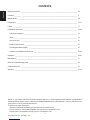 4
4
-
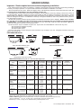 5
5
-
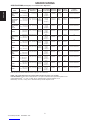 6
6
-
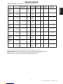 7
7
-
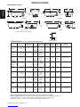 8
8
-
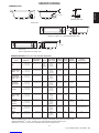 9
9
-
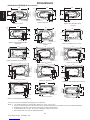 10
10
-
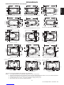 11
11
-
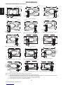 12
12
-
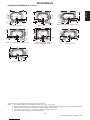 13
13
-
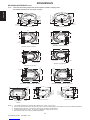 14
14
-
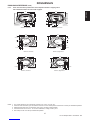 15
15
-
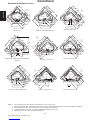 16
16
-
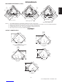 17
17
-
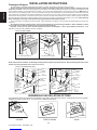 18
18
-
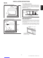 19
19
-
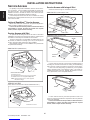 20
20
-
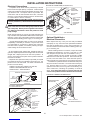 21
21
-
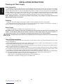 22
22
-
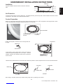 23
23
-
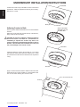 24
24
-
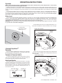 25
25
-
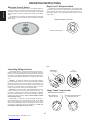 26
26
-
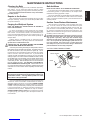 27
27
-
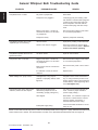 28
28
-
 29
29
-
 30
30
-
 31
31
-
 32
32
-
 33
33
-
 34
34
-
 35
35
-
 36
36
-
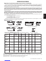 37
37
-
 38
38
-
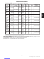 39
39
-
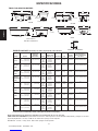 40
40
-
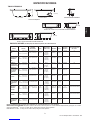 41
41
-
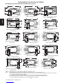 42
42
-
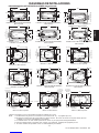 43
43
-
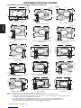 44
44
-
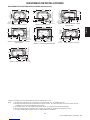 45
45
-
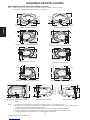 46
46
-
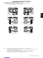 47
47
-
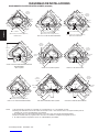 48
48
-
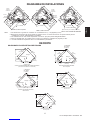 49
49
-
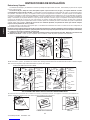 50
50
-
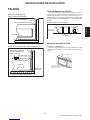 51
51
-
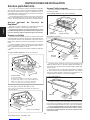 52
52
-
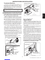 53
53
-
 54
54
-
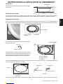 55
55
-
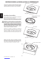 56
56
-
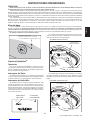 57
57
-
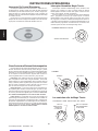 58
58
-
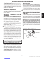 59
59
-
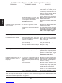 60
60
-
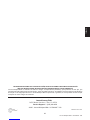 61
61
-
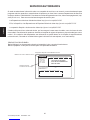 62
62
-
 63
63
-
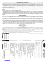 64
64


Jacuzzi Amiga Installation And Operating Instructions Manual
- Categoría
- Calentadores espaciales
- Tipo
- Installation And Operating Instructions Manual
en otros idiomas
- English: Jacuzzi Amiga
Artículos relacionados
-
Jacuzzi SOAKER BATH SERIES Installation And Operation Instructions Manual
-
-
Jacuzzi NOV7242WLR2XXW Guía de instalación
-
Jacuzzi MOF6636WCR2CPWC Guía de instalación
-
-
Jacuzzi P1D6032WLR1XXW Guía de instalación
-
-