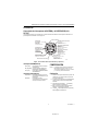
Honeywell Home T8775A1009 Guía de instalación
- Categoría
- Termostatos
- Tipo
- Guía de instalación

1 69-1677ES—1
INSTALLATION INSTRUCTIONS
® U.S. Registered Trademark • Patents Pending
© 2004 Honeywell International Inc.
All Rights Reserved
69-1677ES—1
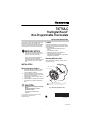
T8775A,C
The Digital Round
™
Non-Programmable Thermostats
The T8775A,C Thermostats provide single-stage
temperature control for 24V systems. The
T8775A,C models include a thermostat, wallplate
(for wiring and mounting thermostat), mounting
screws, wall anchors, and a 4074 FAB resistor.
MERCURY NOTICE
If this control is replacing a control that
contains mercury in a sealed tube, do not
place your old control in the trash.
Contact your local waste management
authority for instructions regarding
recycling and the proper disposal of an old
control containing mercury in a sealed
tube.
INSTALLATION
When Installing this Product…
1. Read these instructions carefully. Failure to
follow them could damage the product or
cause a hazardous condition.
2. Check the ratings given in the instructions
and on the product to make sure the product
is suitable for your application.
3. Installer must be a trained, experienced ser-
vice technician.
4. After installation is complete, check out prod-
uct operation as provided in these instruc-
tions.
CAUTION
Electrical Shock or Equipment Damage
Hazard.
Can shock individuals or short
equipment circuitry.
Disconnect power supply before
installation.
Location
Install the thermostat about 5 ft (1.5m) above the
floor in an area with good air circulation at average
temperature. Do not install the thermostat where it
can be affected by:
— drafts or dead spots behind doors and in
corners.
— hot or cold air from ducts.
— radiant heat from the sun or appliances.
— concealed pipes and chimneys.
— unheated (uncooled) areas such as an outside
wall behind the thermostat.
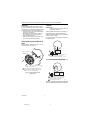
Mounting Wallplate to Wall
Mount the T8775A,C wallplate, with the screws
provided. See Fig. 1.
Fig. 1. Mounting wallplate to wall.
M19499
WALL ANCHORS (2)
WIRING HOLE
WALL PLATE
1 INCH SCREW (2)
1 WHEN USING WALL ANCHORS, DRILL 3/16 IN. HOLES
FOR DRYWALL, 7/32 IN. HOLES FOR PLASTER.
1

T8775A,C THE DIGITAL ROUND™ NON-PROGRAMMABLE THERMOSTATS
69-1677ES—1 2
69-1677ES—1 2
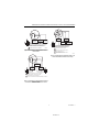
Wiring
IMPORTANT
Use 18-gauge wire to wire the T8775A,C
Thermostats.
All wiring must comply with local electrical codes
and ordinances. Disconnect the power supply to
prevent electrical shock or equipment damage.
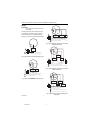
Refer to Fig. 2 through 6 for typical wiring hookups.
Fig. 2. Typical hookup of T8775A in a heat-only system.
Fig. 3. Typical hookup of T8775C in heat-only system
with fan.
Fig. 4. Typical hookup of T8775C in heat-cool system
with single transformer.
Fig. 5. Typical hookup of T8775C in heat-cool system
with two transformers.
Fig. 6. Typical hookup of T8775C in single-stage heat
pump system.
POWER SUPPLY. PROVIDE DISCONNECT MEANS
AND OVERLOAD PROTECTION AS REQUIRED.
W
R
HEATING
RELAY OR
VALVE COIL
M19513
1
1
M19514
HEATING
RELAY OR
VALVE COIL
FAN
RELAY
1 POWER SUPPLY. PROVIDE DISCONNECT MEANS
AND OVERLOAD PROTECTION AS REQUIRED.
2 FACTORY INSTALLED JUMPER.
1
2
W
R
Rc
B
O
Y
G
1
HEATING
RELAY OR
VALVE COIL
COMPRESSOR
CONTACTOR
FAN
RELAY
M19515
1 POWER SUPPLY. PROVIDE DISCONNECT MEANS
AND OVERLOAD PROTECTION AS REQUIRED.
2 FACTORY INSTALLED JUMPER.
2
W
R
Rc
B
O
Y
G
1
2
1
HEATING
RELAY OR
VALVE COIL
COMPRESSOR
CONTACTOR
FAN
RELAY
M19517
1 POWER SUPPLY. PROVIDE DISCONNECT MEANS
AND OVERLOAD PROTECTION AS REQUIRED.
REMOVE FACTORY INSTALLED JUMPER BETWEEN R AND R
C
.
2
W
R
Rc
B
Y
G
1
4
COMPRESSOR
CONTACTOR
HEAT
CHANGEOVER
VALVE
COOL
CHANGEOVER
VALVE
FAN
RELAY
M19516
1 POWER SUPPLY. PROVIDE DISCONNECT MEANS
AND OVERLOAD PROTECTION AS REQUIRED.
2 FACTORY INSTALLED JUMPER.
3 USE A JUMPER WIRE (NOT SUPPLIED) TO CONNECT W TO Y.
4 USE EITHER O OR B FOR HEAT PUMP CHANGEOVER.
3
2
W
R
Rc
B
O
Y
G

T8775A,C THE DIGITAL ROUND™ NON-PROGRAMMABLE THERMOSTATS
3 69-1677ES—1
3 69-1677ES—1
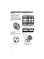
CUSTOMIZE THERMOSTAT
Setting Fuel Switch (T8775C only)
The fuel switch is preset at the factory in the F
position. See Fig. 7. This is the correct setting for gas
or oil systems. If the T8775C is being installed on an
electric heat system, or a heat pump, set the switch to
the E position. The E setting allows the fan to turn on
immediately with the heating equipment in a system
where the G terminal is connected.
Fig. 7. Fuel switch.
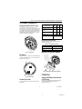
DIP Switch
To adjust the heat cycle rate or the Fahrenheit/Celsius
indication, locate DIP switch 1, 2 and 3 on the back of
the thermostat. See Fig. 8.
Fig. 8. DIP switch.
Set Heat Cycle Rate
Use DIP switches 1 and 2 to set the heat cycle rate.
See Table 1.
Table 1. Heat Cycle Rate.
Fahrenheit/Celsius Indication
Use DIP switch 3 to set the desired temperature
indication. See Table 2.
Table 2. Temperature Indication.
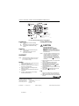
Mounting Thermostat to Wallplate
Fig. 9. Mounting thermostat to wallplate.
OPERATION
Setting SYSTEM and FAN Switches
(T8775C only)
System and fan settings are controlled manually by
using the switches located at the top of the
thermostat. See Fig. 10.
M19497
FUEL SWITCH
ON
1 2 3
M19567
BACK OF THERMOSTAT
DIP SWITCH
Heating System
Cycles
Per
Hour
DIP
Switch
1
DIP
Switch
2
Steam, Gravity 1 On On
High Efficiency Warm Air
(90%+ efficiency), Hot Water,
Heat Pump
3OffOn
Gas or Oil Warm Air (factory
setting)
6OffOff
Electric Warm Air 9 On Off
In Floor Radiant Heat Check with manufacturer
for recommended cycle
rate.
Fahrenheit/Celsius
Display DIP Switch 3
Fahrenheit (factory setting) Off
Celsius On
M19498
ENGAGE TABS
AT BOTTOM OF
THERMOSTAT
AND WALL PLATE.
PRESS UPPER
EDGE OF CASE
TO LATCH

T8775A,C THE DIGITAL ROUND™ NON-PROGRAMMABLE THERMOSTATS
69-1677ES—1 4
69-1677ES—1 J.S. Rev. 6-04 Printed in Hungary www.honeywell.com/yourhome
Automation and Control Solutions
Honeywell International Inc. Honeywell Limited-Honeywell Limitée
1985 Douglas Drive North 35 Dynamic Drive
Golden Valley, MN 55422 Scarborough, Ontario
M1V 4Z9
Fig. 10. T8775 Thermostat (features and operation).
SYSTEM Switch
Heat: The thermostat controls the heating
system.
Off: Both heating and cooling systems are off.
Cool: The thermostat
controls the cooling
system.
FAN Switch
Auto: The fan only runs with the heating and
cooling system.
On: The fan runs continuously. Use for
improved air circulation.
CHECKOUT
NOTE: Temperature setpoint range is 40°F to 90°F
(4°C to 32°C) in heating and 45°F to 99°F
(7°C to 37°C) in cooling.
Heating
1. Slide the SYSTEM switch to Heat and the FAN
switch to Auto (T8775C only).
2. Raise the temperature setpoint several degrees
above the room temperature.
3. A flame will appear in the display and the
heat should turn on.
4. Lower the temperature setpoint below the room
temperature.
5. The flame will disappear from the display
and the heat should turn off.
Cooling (T8775C only)
CAUTION
Low Temperature Hazard.
Operating at too low of an outdoor
temperature may cause compressor
damage.
Do not operate cooling if outdoor temperature
is below 50°F (10°C). Refer to manufacturer’s
recommendations.
NOTE: If a call for cooling is made before the com-
pressor has been off for five minutes, or if a
power interruption occurs while the com-
pressor is running, the thermostat will go
into a five-minute delay to protect the com-
pressor. The snowflake will flash during
this delay.
1. Slide the SYSTEM switch to Cool and the FAN
switch to Auto.
2. Lower the temperature setpoint several
degrees below the room temperature.
3. After approximately five minutes, the thermo-
stat will display a solid snowflake and the
cooling should turn on.
4. Raise the temperature setpoint above the room
temperature.
5. The snowflake will disappear from the dis-
play and the cooling should turn off.
Fan
1. Slide the SYSTEM switch to Off and the FAN
switch to On. The fan should run continuously.
2. Slide the FAN switch to Auto. The fan should
turn off.
ROOM
SET
DISPLAYS ROOM
OR SET TEMPERATURE
M19520
SHOWS THAT THE
CURRENT TEMPERATURE
SETPOINT IS DISPLAYED.
(T8775C ONLY)
SELECTS
ON/AUTO
(T8775C ONLY)
SELECTS
COOL/OFF/HEAT
DISPLAYS AND ADJUSTS
TEMPERATURE SETPOINT/TURNS
BACKLIGHT ON
SHOWS THAT THE
CURRENT ROOM
TEMPERATURE IS
DISPLAYED.

1XX-XXXX—X
INSTRUCCIONES DE INSTALACIÓN
® Marca comercial registrada de EE.UU. • Patentes pendientes
Copyright © 2004, Honeywell International Inc.
Todos los derechos reservados 69-1677ES—1
Termostatos no programables
The Digital Round
™
T8775A, C
Los termostatos T8775A, C ofrecen control de
temperatura de una etapa para sistemas de 24 V.
Los modelos T8775A, C incluyen un termostato,
una placa de fijación (para cablear y montar el
termostato), tornillos de montaje, anclas de pared y
una resistencia FAB 4074.
MERCURY NOTICE
Si este control reemplaza un control que
contiene mercurio en un tubo sellado, no
tire el control usado a la basura.
Póngase en contacto con sus autoridades
locales de manejo de residuos para recibir
instrucciones relacionadas con el reciclaje
y disposición adecuados de un control
usado que contenga mercurio en un tubo
sellado.
INSTALACIÓN
Al instalar este producto...
1. Lea con cuidado estas instrucciones. De no
seguirlas se podría dañar el producto o
provocar una situación peligrosa.
2. Verifique los valores nominales de las
instrucciones y del producto para asegurarse
de que el producto sea adecuado para su
aplicación.
3. El instalador debe ser un técnico de servicio
capacitado y experimentado.
4. Después de terminar la instalación, verifique
la operación del producto tal como se indica
en estas instrucciones.
CAUTION
Peligro de descarga eléctrica o de
daños al equipo.
Puede dar una descarga a la persona o
provocar un corto circuito en el equipo.
Desconecte la fuente de alimentación
antes de la instalación.

TERMOSTATOS DIGITALES THE DIGITAL ROUND™ T8775A, C NO PROGRAMABLES
XX-XXXX—X 2
69-1677ES—1 2
Ubicación
Instale el termostato aproximadamente a 1.5 m (5
pies) por arriba del suelo, en un área con buena
circulación de aire a temperatura media. No instale
el termostato donde pueda verse afectado por:
— Corrientes de aire o puntos ciegos detrás de las
puertas y en las esquinas.
— Aire caliente o frío proveniente de conductos.
— Calor radiante del sol o de otros aparatos.
— Tubos y chimeneas ocultos.
— Áreas sin calefacción (sin enfriamiento) como
un muro exterior detrás del termostato.
Cómo montar la placa de fijación al
muro
Monte la placa de fijación del T8775A, C con los
tornillos incluidos. Vea la Figura 1.
Figura. 1. Cómo montar la placa de
fijación al muro.
Cableado
IMPORTANTE
Utilice alambre calibre 18 para cablear los
termostatos T8775A, C.
Todo el cableado debe cumplir con los códigos y
reglamentos eléctricos locales. Desconecte la
fuente de alimentación para prevenir una descarga
eléctrica o daños al equipo.
Consulte las Figuras 2 a 6 para ver las conexiones
de cableado típicas.
Figura. 2. Conexión típica del termostato T8775A en un
sistema exclusivamente de calefacción.
Figura. 3. Conexión típica del termostato T8775C en un
sistema exclusivamente de calefacción con ventilador.
MS19499
ANCLAS DE PARED (2)
ORIFICIO PARA EL CABLEADO
PLACA DE
MONTAJE
TORNILLO DE 1 PULGADA (2)
1 CUANDO USE ANCLAS DE PARED PERFORE HAGA
ORIFICIOS DE 3/16 PULGADA PARA TABLARROCA Y
ORIFICIOS DE 7/32 PULGADA PARA YESO
1
FUENTE DE ALIMENTACIÓN. INCLUYA MEDIOS DE
DESCONEXIÓN Y PROTECCIÓN CONTRA
SOBRECARGAS SEGÚN SE REQUIERA.
W
R
MS19513
1
1
RELEVADOR DE
CALEFACCIÓN
O BOBINA
DE VÁLVULA
MS19514
1 FUENTE DE ALIMENTACIÓN. INCLUYA MEDIOS
DE DESCONEXIÓN Y PROTECCIÓN CONTRA
SOBRECARGAS SEGÚN SE REQUIERA.
2 PUENTE INSTALADO EN FÁBRICA.
1
2
W
R
Rc
B
O
Y
G
RELEVADOR DE
CALEFACCIÓN
O BOBINA DE
VÁLVULA
RELEVADOR
DEL
VENTILADOR

TERMOSTATOS DIGITALES THE DIGITAL ROUND™ T8775A, C NO PROGRAMABLES
3XX-XXXX—X
3 69-1677ES—1
Figura. 4. Conexión típica del termostato T8775C en
un sistema de calefacción-enfriamiento con un
transformador.
Figura. 5. Conexión típica del termostato T8775C en
un sistema de calefacción-enfriamiento con dos
transformadores.
Figura. 6. Conexión típica del termostato T8775C en un
sistema de bomba de calefacción de una etapa.
1
RELEVADOR DE
CALEFACCIÓN
O BOBINA
DE VÁLVULA
CONTACTOR DEL
COMPRESOR
MS19515
2
W
R
Rc
B
O
Y
G
RELEVADOR
DEL
VENTILADOR
2 PUENTE INSTALADO EN FÁBRICA.
1 FUENTE DE ALIMENTACIÓN. INCLUYA MEDIOS
DE DESCONEXIÓN Y PROTECCIÓN CONTRA
SOBRECARGAS SEGÚN SE REQUIERA.
1
2
1
CONTACTOR DEL
COMPRESOR
MS19517
1 FUENTE DE ALIMENTACIÓN. INCLUYA MEDIOS
DE DESCONEXIÓN Y PROTECCIÓN CONTRA
SOBRECARGAS SEGÚN SE REQUIERA.
QUITE EL PUENTE INSTALADO EN FÁBRICA ENTRE R Y R
C
.
2
W
R
Rc
B
Y
G
RELEVADOR
DEL
VENTILADOR
RELEVADOR DE
CALEFACCIÓN
O BOBINA
DE VÁLVULA
1
4
VÁLVULA DE
CONMUTACIÓN
DE CALOR
VÁLVULA DE
CONMUTACIÓN
DE FRÍO
MS19516
1 FUENTE DE ALIMENTACIÓN. INCLUYA MEDIOS
DE DESCONEXIÓN Y PROTECCIÓN CONTRA
SOBRECARGAS SEGÚN SE REQUIERA.
2 PUENTE INSTALADO EN FÁBRICA.
3 USE UN CABLE PUENTE (NO INCLUIDO)
PARA CONECTAR "W" A "Y".
4 USE "O" O "B" PARA LA CONMUTACIÓN
DE LA BOMBA DE CALOR.
3
2
W
R
Rc
B
O
Y
G
CONTACTOR DEL
COMPRESOR
RELEVADOR
DEL
VENTILADOR

TERMOSTATOS DIGITALES THE DIGITAL ROUND™ T8775A, C NO PROGRAMABLES
XX-XXXX—X 4
69-1677ES—1 4
CONFIGURE EL TERMOSTATO
A SU GUSTO
Cómo ajustar el interruptor de
combustible (sólo T8775C)
El interruptor de combustible se ajusta en la fábrica
en la posición F. Vea la Figura 7. Este es el ajuste
correcto para sistemas de gas o de petróleo. Si el
termostato T8775C se va a instalar en un sistema de
calefacción eléctrica o en una bomba de calor, ajuste
el interruptor en la posición E. El ajuste E permite que
el ventilador se encienda de inmediato con el sistema
de calefacción, en un sistema en el que se tenga
conectada la terminal G.
Figura. 7. Interruptor de combustible.
Interruptor DIP
Para ajustar la razón del ciclo de calor o la indicación
de grados Fahrenheit/Celsius, localice el interruptor
DIP 1, 2 y 3 en la parte trasera del termostato. Vea la
Figura 8.
Figura. 8. Interruptor DIP.
Ajuste la razón del ciclo de calor
Utilice los interruptores DIP 1 y 2 para ajustar la razón
del ciclo de calor. Vea la Tabla 1.
Tabla 1. Razón del ciclo de calor.
Indicación de grados Fahrenheit/Celsius
Utilice el interruptor DIP 3 para ajustar la indicación
de la temperatura deseada. Vea la Tabla 2.
Tabla 2. Indicación de la temperatura.
Montaje del termostato a la placa de
fijación
Figura. 9. Montaje del termostato a
la placa de fijación.
MS19497
INTERRUPTOR DE COMBUSTIBLE
ON
1 2 3
MS19567
INTERRUPTOR
DIP
Sistema de
calefacción
Ciclos
por
hora
Interruptor
DIP 1
Interruptor
DIP 2
Vapor, gravedad 1 Encendido Encendido
Aire caliente de alta
eficiencia (Eficiencia
mayor de 90 %),
agua caliente, bomba
de calor
3 Apagado Encendido
Aire cálido de gas o
petróleo (ajuste de
fábrica)
6 Apagado Apagado
Aire cálido eléctrico 9 Encendido Apagado
Calor radiante en el
piso
Verifique la razón del ciclo
recomendada por el fabricante.
Pantalla de grados
Fahrenheit/Celsius Interruptor DIP 3
Fahrenheit (ajuste de
fábrica)
Apagado
Celsius Encendido
MS19498
ENGANCHE LAS LENGÜETAS
EN LA PARTE INFERIOR DEL
TERMOSTATO Y LA PLACA
DE FIJACIÓN
PRESIONE EL BORDE
SUPERIOR DE LA CAJA
PARA CERRAR

TERMOSTATOS DIGITALES THE DIGITAL ROUND™ T8775A, C NO PROGRAMABLES
5XX-XXXX—X
5 69-1677ES—1
OPERACIÓN
Cómo ajustar los interruptores del SISTEMA y del VENTILADOR (sólo
T8775C)
Los ajustes del sistema y del ventilador se controlan manualmente utilizando los interruptores situados en la
parte superior del termostato. Vea la Figura 10.
Figura. 10. Termostato T8775 (características y operación).
Interruptor SYSTEM (Sistema)
Heat (Calor): El termostato controla el sistema.
de calefacción.
Off (Apagado): Los dos sistemas (calefacción y
enfriamiento) están apagados.
Cool (Frío): El termostato
controla el sistema
de enfriamiento.
Interruptor FAN (ventilador)
Auto(mático): El ventilador solamente funciona
con el sistema de calefacción y de
enfriamiento.
Encendido El ventilador funciona
continuamente. Se usa para tener
una mejor circulación de aire.
COMPROBACIÓN
NOTA: El intervalo de los puntos de referencia de
temperatura es de 40°F a 90°F (4 °C a
32°C) para la calefacción y de 45 °F a 99 °F
(7°C a 37°C) para el enfriamiento.
Calefacción
1. Deslice el interruptor SYSTEM a la posición de
calefacción y el interruptor FAN a la posición
Auto (sólo el T8775C).
2. Aumente el punto de referencia de temperatura
varios grados por arriba de la temperatura
ambiente.
3. Debe aparecer una flama en la pantalla y
debe encenderse la calefacción.
4. Baje el punto de referencia de temperatura
debajo de la temperatura ambiente.
5. La flama debe desaparecer de la pantalla y
debe apagarse la calefacción.
ROOM
SET
MUESTRA LA TEMPERATURA
AMBIENTE O CONFIGURADA
MS19520
MUESTRA QUE SE
VISUALIZ
A EL PUNTO DE
REFERENCIA DE LA
TEMPERATURA ACTUAL.
(SÓLO T8775C)
SELECCIONA
ENCENDIDO/AUTOMÁTICO
(SÓLO T8775C)
SELECCIONA
FRÍO/APAGADO/CALOR
MUESTRA Y AJUSTA EL PUNTO
DE REFERENC
IA DE
TEMPERATURA/ENCIENDE
LA LUZ DE FONDO
MUESTRA QUE SE
VISUALIZA LA TEMPERATURA
AMBIENTE ACTUAL.
PLACA DE MONTAJE
INTERRUPTOR
DEL SISTEMA
INTERRUPTOR DEL VENTILADOR
INDICADOR DE TEMPERATURA
AMBIENTE
INDICADOR DE AJUSTES DE
TEMPERATURA
DISCO GRADUADO
BOTÓN PARA LUZ DE FONDO
PANTALLA DIGITAL
INDICADORES QUE
MUESTRAN QUE EL
TERMOSTATO HA DADO
LA SEÑAL DE
CALEFACCIÓN
O ENFRIAMIENTO

TERMOSTATOS DIGITALES THE DIGITAL ROUND™ T8775A, C NO PROGRAMABLES
XX-XXXX—X 6
69-1677ES—1 6
Enfriamiento (sólo T8775C)
CAUTION
Peligro con la baja temperatura
Si se opera a una temperatura demasiado
baja en comparación con la temperatura
exterior pueden provocarse daños al
compresor.
No opere el enfriamiento si la temperatura
exterior está por debajo de 50°F (10°C).
Consulte las recomendaciones del fabricante.
NOTA: Si se trata de activar el enfriamiento antes
de que el compresor haya estado apagado
durante cinco minutos , o si se interrumpe la
electricidad mientras el compresor está
funcionando, el termostato entrará en un
retraso de cinco minutos para proteger al
compresor. El símbolo de copo de nieve
va a parpadear durante este retraso.
1. Deslice el interruptor SYSTEM a la posición de
enfriamiento y el interruptor FAN a la posición
Auto.
2. Baje el punto de referencia de temperatura
varios grados por debajo de la temperatura
ambiente.
3. Después de aproximadamente cinco minutos,
el termostato mostrará el símbolo del copo de
nieve sólido y se debe encender el
enfriamiento.
4. Aumente el punto de referencia de temperatura
por arriba de la temperatura ambiente.
5. El copo de nieve debe desaparecer de la
pantalla y debe apagarse el enfriamiento.
Ventilador
1. Deslice el interruptor SYSTEM a la posición de
apagado y el interruptor FAN a la posición de
encendido. El ventilador debe funcionar de
manera continua.
2. Deslice el interruptor FAN a la posición Auto.
El ventilador debe apagarse.

7XX-XXXX—X
7 69-1677ES—1

XX-XXXX—X 8
69-1677ES—1 J.S. Rev. 6-04 Impreso en Hungría www.honeywell.com/yourhome
Soluciones de automatización y control
Honeywell International Inc. Honeywell Limited-Honeywell Limitée
1985 Douglas Drive North 35 Dynamic Drive
Golden Valley, MN 55422 Scarborough, Ontario
M1V 4Z9
-
 1
1
-
 2
2
-
 3
3
-
 4
4
-
 5
5
-
 6
6
-
 7
7
-
 8
8
-
 9
9
-
 10
10
-
 11
11
-
 12
12


Honeywell Home T8775A1009 Guía de instalación
- Categoría
- Termostatos
- Tipo
- Guía de instalación
en otros idiomas
Artículos relacionados
Otros documentos
-
Honeywell T8775A,C El manual del propietario
-
Honeywell PRO TH1100D Manual de usuario
-
Honeywell W8835 Manual de usuario
-
Honeywell Thermostat TH1100DH Manual de usuario
-
-
Robertshaw RS2110 Manual de usuario
-
-
Honeywell FOCUSPROTM TH5000 Manual de usuario
-
-