Chauvin-Arnoux CA5001 El manual del propietario
- Tipo
- El manual del propietario

1
■■
■■
■MULTIMETRE
■■
■■
■MULTIMETER
■■
■■
■MULTIMETER
■■
■■
■MULTIMETRO
■■
■■
■MULTIMETRO
C.A 5001
FRANCAIS Notice de fonctionnement
ENGLISH User's manual
DEUTSCH Bedienungsanleitung
ITALIANO Libretto d'Istruzioni
ESPANOL Manual de Empleo

2
Signification du symbole
Vous venez d’acquérir un multimètre C.A 5001 et nous vous
remercions de votre confiance.
Pour obtenir le meilleur service de votre appareil :
- lisez attentivement cette notice de fonctionnement,
- respectez les précautions d’emploi.
PRÉCAUTIONS D'EMPLOI
■Ne jamais utiliser sur des réseaux de tension supérieure
à 600 V par rapport à la terre. Ce multimètre, de catégorie de
surtension III, répond aux exigences de fiabilité et de disponibilité
sévères correspondant aux installations fixes industrielles et
domestiques (cf. IEC 664-1).
■Utilisation en intérieur dans des environnements de degré de
pollution au plus égal à 2 (cf. IEC 664-1), de température
de -10 à + 55°C et d’humidité relative inférieure à 90%.
■Respecter la valeur et le type des fusibles sous risque de
détérioration de l'appareil et d'annulation de la garantie.
- Fusible 5A HPC (6,3 x 32 mm - 500 V - 20 kA)
- Fusible 0,5A HPC (6,3 x 32 mm - 500 V - 20 kA)
■Utilisez des accessoires conformes aux normes de sécurité
(NF EN 61010-2-031) de tension minimale 600 V et de catégorie
de surtension III.
■Avant toute mesure, s'assurer du positionnement correct des
cordons et du commutateur. Lorsque l'ordre de grandeur d'une
mesure n'est pas connu, placer le commutateur sur le calibre le
plus élevé puis baisser progressivement, si nécessaire, jusqu'au
calibre approprié : la lecture doit s'effectuer, de préférence, dans
les 2/3 supérieurs de l'échelle.
■Ne jamais mesurer de résistances sur un circuit sous tension. Si
le tarage n'est plus possible, remplacer la pile.
■Lors de mesures d'intensités (sans pince ampèremétrique),
interrompre l'alimentation du circuit avant de brancher ou de
débrancher votre multimètre.
■Pour ouvrir la trappe à pile, il faut obligatoirement déconnecter les
cordons.
■Ne jamais raccorder au circuit à mesurer si la trappe à pile n'est
pas correctement refermée.
ATTENTION ! Consulter la notice de fonctionnement avant
d'utiliser l'appareil. Dans la présente notice de fonctionnement, les
instructions précédées de ce symbole, si elles ne sont pas bien
respectées ou réalisées, peuvent occasionner un accident corporel
ou endommager l'appareil et les installations.
Signification du symbole
Cet appareil est protégé par une isolation double ou une isolation
renforcée. Il ne nécessite pas de raccordement à la borne de terre
de protection pour assurer la sécurité électrique.

3
ENGLISH ................................................................................................ 10
DEUTSCH ............................................................................................... 18
ITALIANO ............................................................................................... 26
ESPANOL ............................................................................................... 34
SOMMAIRE
1 - PRÉSENTATION
...
Page
1-Présentation ......................................................... 3
2 - Description........................................................... 4
3 - Tensions continues et alternatives (V et ~) ... 5
4-Décibels (dB) ....................................................... 5
5 - Intensités (A et ~) ........................................... 6
6-Résistances (Ω) .................................................. 7
7 - Test sonore de continuité [ ] ......................... 7
8 - Caractéristiques générales ................................. 7
9 - Accessoires et rechanges (Pour commander) . 8
10 - Garantie ............................................................... 8
11 - Maintenance ........................................................ 9
12 - Annexe ............................................................... 42
...
...
Le multimètre C.A 5001 est destiné aux besoins quotidiens des
professionnels de l'électricité. Il dispose des fonctions suivantes :
- Voltmètre : mesure des tensions (V et ~)
- Ampèremètre : mesure des intensités (A et ~)
- Ohmmètre : mesure des résistances (
Ω)
- Test sonore de continuité [ ]
Il permet aussi la mesure de niveaux en décibels (dB), sur les calibres
voltmètre alternatif.
Le cadran est équipé d'un voyant de contrôle des fusibles (Fus).
NB : Toujours utiliser des accessoires adaptés à la tension et à la
catégorie de surtension du circuit à mesurer (selon NF EN 61010).
...

4
5 BOUTON DE TARAGE
Potentiomètre de réglage de zéro en ohmmètre (tarage).
Si le tarage de l'ohmmètre n'est plus possible, remplacer la pile.
(Voir dessin en 12 - ANNEXE)
1 BORNES
Bornes de sécurité Ø 4 mm
■COM : commun, borne recevant le cordon noir
■
VΩΩ
ΩΩ
Ω : borne recevant le cordon rouge pour les tensions et résistances
■5A : borne recevant le cordon rouge pour les calibres 5A
■mA : borne recevant le cordon rouge pour les calibres mA
2 - DESCRIPTION
3 VOYANT "FUS"
Néon de contrôle des fusibles 0,5 A et 5 A en mesure d'intensité.
Si le voyant "Fus" s'allume, changer le(s) fusible(s)
défectueux.
NB : Ce voyant nécessite la présence d'une tension
≥
80 V pour
s'allumer.
4 COMMUTATEUR
Commutateur à 24 positions pour sélectionner les fonctions et
calibres.
2 AFFICHEUR ANALOGIQUE
Le cadran comprend 6 échelles :
■2 échelles noires, avec miroir antiparallaxe,
pour les V et ~ (0.100 et 0.30)
■1 échelle verte pour les Ω (0.10 k)
■1 échelle noire pour les A (0.50)
■1 échelle rouge pour les A ~ (0.50)
■1 échelle rouge pour les dB (0.22)
...
...

5
4 - DÉCIBELS
■ Rappel. La mesure d'une tension alternative peut être exprimée
en décibel (symbole dB). Le décibel est le rapport de deux grandeurs
ou niveau. Le niveau N, en dB d'une tension U a pour expression
mathématique :
U0 est la tension de référence de 0,775 V ~ pour une puissance
P0 de 1mW sur une charge de 600 Ω.
■ Utilisation. Le niveau zéro de l'échelle rouge en dB correspond à
U0=0,775 V pour le calibre 10 V ~. La lecture est directe en dB pour
le calibre 10 V ~ de 0 à +22 dB. Pour les autres calibres, il est possible
de lire en dB (valeur approchée) en ajoutant respectivement :
+10 dB sur le calibre 30 V ~ +20 dB sur le calibre 100 V ~
+30 dB sur le calibre 300 V ~ +40 dB sur le calibre 1000 V ~
3 - TENSIONS CONTINUES ET ALTERNATIVES
■Raccorder les cordons au multimètre et se brancher en parallèle
sur le circuit à contrôler.
■Lorsque l'ordre de grandeur n'est pas connu, placer le commuta-
teur sur le calibre le plus élevé puis baisser progressivement
jusqu'au calibre approprié.
■Pour obtenir la tension en V, multiplier la valeur lue sur l'échelle
appropriée par le coefficient de lecture indiqué dans le tableau.
(1) Commun au calibre 50µA (2) Lecture directe en mV
(3) R spécifique : 20 kΩ/V, sauf calibre 1000 V- R = 6,32 kΩ/V
(4) En % de la fin d'échelle (5) Pendant 15 secondes
(1) R spécifique :
6,32 kΩ/V
(2) En % de
la fin d'échelle
(3) De 20 Hz à ...
(4) Pendant
15 secondes
()
NdB) UU(log=20 10 0
V
100 mV
(1) 1 V 3 V 10 V 30 V 100 V 300 V 1000 V
Echelle 100 100 30 100 30 100 30 100
Coefficient
de lecture x1(2) x0,01 x0,1 x0,1 x1 x1 x10 x10
Résistance
interne (3)
2 kΩ20 kΩ63,2 kΩ200 kΩ632 kΩ2 MΩ6,32 MΩ6,32 MΩ
Précision
(
4) 2,5 % 1,5 %
Surcharge
admissible 440 V 1000 V(5)
1500 V
(5)
...
V
~
10 V 30 V 100 V 300 V 1000 V
Echelle 100 30 100 30 100
Coefficient
de lecture x0,1 x1 x1 x10 x10
Résistance
interne (1) 63,2 kΩ200 kΩ632 kΩ2 MΩ6,32 MΩ
Précision
(2) 3 % 2,5 %
Bande 100 kHz 50 kHz 25 kHz 1 kHz
passante (3)
Surcharge
admissible 440 V 1000 V(4) 1500 V(4)

6
(1) Bande passante : 40 Hz à 5 kHz. (3) En % de la fin d'échelle.
(2) Sans les cordons. Résistance de la paire de cordons fournis : environ 70 m Ω.
■Lorsque l'ordre de grandeur n'est pas connu, placer le commuta-
teur sur le calibre le plus élevé puis baisser progressivement
jusqu'au calibre approprié.
■Pour obtenir l'intensité en mA ou A, multiplier la valeur lue sur
l'échelle apppropriée par le coefficient de lecture indiqué dans le
tableau.
5 - INTENSITÉS CONTINUES ET ALTERNATIVES
Toujours interrompre le circuit à contrôler avant de connecter
le multimètre sur le circuit. Si le voyant "Fus" s'allume, changer
le(s) fusible(s) défectueux (Rappel : tension minimum de 80V).
Raccorder les cordons au multimètre et se brancher en série
dans le circuit avec :
- le cordon rouge dans la borne "mA", jusqu'à 500 mA
- le cordon rouge dans la borne "5 A", de 500 mA à 5 A
Interrompre l'alimentation du circuit avant de changer de
calibre.
(1) Commun au calibre 100 mV (2) Lecture directe en µA
(3) Sans les cordons. Résistance de la paire de cordons fournis : environ 70 m Ω.
(4) En % de la fin d'échelle.
...
...
Limitation 10 min. de marche, 5 min. d'arrêt jusqu'à +40°C maxi.
Limitation 10 min. de marche, 5 min. d'arrêt jusqu'à +40°C maxi.
A50 µA
(1)
5 mA 50 mA 500 mA 5 A
Echelle 50 noire
Coefficient
de lecture x1
(2)
x0,1 x1 x10 x0,1
Chute de
tension aux
bornes
(3)
100 mV 700 mV 900 mV 2 V 1,3 V
Précision
(4)
2,5 % 5 %
Protection Fusible 0,5 A HPC Fus. 5 A
HPC
A ~
(1)
5 mA 50 mA 500 mA 5 A
Echelle 50 rouge
Coefficient
de lecture x0,1 x1 x10 x0,1
Chute de
tension aux
bornes
(2)
700 mV 800 mV 2 V 1,3 V
Précision
(3)
2,5 % 5 %
Protection Fusible 0,5 A HPC Fus. 5 A
HPC
Ne pas utiliser l'entrée A ~ sur des transformateurs d'intensité
non protégés.
~

7
■Se brancher aux bornes du circuit ou du composant à contrôler.
■Pour obtenir la résistance en Ω, multiplier la valeur lue sur l'échelle
Ω (verte) par le coefficient du calibre sélectionné : x 1 ou x 100
6 - RÉSISTANCES
Ne jamais contrôler une résistance sur un circuit sous tension.
L'alimentation de l'ohmmètre est assurée par une pile 1,5 V.
Si le tarage ne peut pas être effectué remplacer la pile.
7 - TEST SONORE DE CONTINUITÉ
■Raccordement et caractéristiques : idem Résistances
■Placer le commutateur sur la fonction x 1
■Emission d'un bip sonore continu pour une résistance R < 50 Ω
8 - CARACTÉRISTIQUES GÉNÉRALES
8-1 Dimensions et masse
■56 x 105 x 160 mm ■500 g
8-2 Alimentation
■Une pile 1,5 V (type R6 ou LR6 alcaline)
■Autonomie : 10 000 mesures de 15 secondes avec pile alcaline
(1) Commun à la fonction test
sonore de continuité
(2) En % à mi-échelle.
■Tarage - Raccorder les cordons au multimètre.
Placer le commutateur sur le calibre Ω approprié.
Court-circuiter les pointes de touche et amener l'aiguille à 0 sur
l'échelle Ω verte en utilisant le potentiomètre de tarage.
Ωx1
(1)
x100
Etendue de
mesure
5 Ω à
10 kΩ
500 Ω
à 1 MΩ
Résistance
interne 140 Ω1400 Ω
Courant fin
d’échelle 10 mA 100 µA
Précision
(2)
10 %
Surcharge
admissible 440 V

8
Utiliser les désignations et références ci-dessous.
C.A 5001 .................................................................... P01.1965.21E
Livré avec un jeu de 2 cordons à pointe de touche,
une pile 1,5 V et ce mode d'emploi.
Accessoires et rechanges
■Sacoche de transport (240 x 230 x 70 mm) ....... P01.2980.33
■Etui de transport (220 x 180 x 75 mm).................. P01.2980.36
■Jeu de 2 cordons à pointe de touche (NF EN 61010) ... P01.2980.84
■Jeu de 10 fusibles 0,5 A HPC ( 6,3 x 32 mm ) ..... P01.2970.28
■Jeu de 10 fusibles 5 A HPC ( 6,3 x 32 mm ) ........ P01.2970.35
Différents accessoires de mesure élargissent le champ d'applica-
tions ou confèrent de nouvelles fonctions à votre multimètre.
Documentation sur demande.
NB : Toujours utiliser des accessoires adaptés à la tension et à la
catégorie de surtension du circuit à mesurer (selon NF EN 61010).
9 - POUR COMMANDER
Notre garantie s’exerce, sauf stipulation expresse, pendant trois ans
après la date de mise à disposition du matériel (extrait de nos
Conditions Générales de Vente, communiquées sur demande).
10 - GARANTIE
8-3 Conditions climatiques
■Température : utilisation : -10°C à +55°C / stockage : -40°C à +70°C
■Humidité relative :
utilisation : ≤ 90 % HR / stockage : ≤ 95 % HR
■Altitude : utilisation < 2000 m
8-4 Conformité aux normes internationales
8-4-1 Sécurité électrique (NF EN 61010-1, Ed. 95)
■Double isolation : ■Catégorie d'installation : III
■Degré de pollution : 2 ■Tension assignée : 600 V
8-4-2 Compatibilité électromagnétique : conforme CE
■Emission (NF EN 61326-A1, Ed. 98)
■Immunité (NF EN 61326-A1, Ed. 98)
8-4-3 Protection mécanique
■Degré d'étancheité (NF EN 60529, Ed. 92) : indice de protection IP 40

9
11-2 Stockage
Si le multimètre n'est pas mis en service pendant une durée dépassant
60 jours, enlever la pile et stocker la séparément.
11-3 Nettoyage
■Le multimètre doit être déconnecté de toute source électrique.
■Pour nettoyer le boîtier, utiliser un chiffon légèrement imbibé
d'eau savonneuse. Essuyer avec un chiffon humide. Ensuite,
sécher rapidement avec un chiffon ou de l'air pulsé.
11-4 Vérification métrologique
Comme tous les appareils de mesure ou d’essais,
une vérification périodique est nécessaire.
Pour les vérifications et étalonnages de vos appareils, adressez vous
à nos laboratoires de métrologie accrédités par le COFRAC ou aux
agences MANUMESURE.
Renseignements et coordonnées sur demande :
Tél. : 02 31 64 51 43 Fax : 02 31 64 51 09
11-5 Réparation sous garantie et hors garantie
Adressez vos appareils à l'une des agences régionales
MANUMESURE, agréées CHAUVIN ARNOUX
Renseignements et coordonnées sur demande :
Tél. : 02 31 64 51 43 Fax : 02 31 64 51 09
11-6 Réparation hors de France métropolitaine
Pour toute intervention sous garantie ou hors garantie, retournez
l’appareil à votre distributeur.
11 - MAINTENANCE
Pour la maintenance, utilisez seulement les pièces de
rechange qui ont été spécifiées. Le fabricant ne pourra
être tenu pour responsable de tout accident survenu
suite à une réparation effectuée en dehors de son
service après-vente ou des réparateurs agréés.
11-1 Remplacement de la pile et des fusibles
Pour votre sécurité, il faut obligatoirement déconnecter les
cordons du multimètre pour ouvrir la trappe à pile.
■Pour ouvrir la trappe, tourner la vis 1/4 de tour, dans le sens inverse
des aiguilles d'une montre, à l'aide d'une pièce ou d'un tournevis.
■Remplacer la pile usagée par une pile 1,5 V (type R6 ou LR6).
■Remplacer les fusibles défectueux en respectant leur valeur et
leur type :
- Fusible 0,5 A HPC (6,3 x 32 mm - 500 V - 20 kA)
- Fusible 5 A HPC (6,3 x 32 mm - 500 V - 20 kA)
■Remonter la trappe avant d'utiliser le multimètre.

10
Meaning of the symbol
Thank you for purchasing a C.A 5001 Multimeter.
To get the best service from this instrument:
- read this user’s manual carefully,
- respect the safety precautions detailed.
SAFETY PRECAUTIONS
■Never use on networks at a voltage above 600 V in relation to the
earth. This multimeter of overvoltage category III, satisfies the
severe requirements of reliability and availability corresponding to
industrial and domestic permanent installations (c.f. IEC 664-1).
■Use indoors in environments of degree of pollution at most equal
to 2 (c.f. IEC 664-1), of temperature from -10 to +55°C and of relative
humidity less than 90%.
■Respect the value and the type of fuses or there is a risk of
damage to the instrument and cancellation of the warranty.
- Fuse 5 A HBC (6.3 x 32 mm - 500 V - 20 kA)
- Fuse 0.5 A HBC (6.3 x 32 mm - 500 V - 20 kA)
■Use accessories in conformity with safety standards (NF EN 61010-
2-031) of minimum voltage 600 V and overvoltage category III.
■Before any measurement, check the leads and the switch are in
the correct position. When the order of magnitude of a measurement
is not known, place the selector switch on the highest range then
lower progressively, if necessary, to the appropriate range: the
reading must be made, preferably, in the upper 2/3 of the scale.
■Never measure resistances on a live circuit. If zero reset is not
possible, replace the battery.
■During current measurements (without current clamp), switch off
the power supply of the circuit before connecting or disconnecting
your multimeter.
■To open the battery compartment, the leads must be disconnected.
■Never connect to the circuit to be measured if the battery
compartment is not correctly closed.
Warning ! Please refer to the User’s Manual before using the
instrument. In this User’s Manual, the instructions preceded by the
above symbol, should they not be carried out as shown, can result
in a physical accident or damage the instrument and the installations.
Meaning of the symbol
This device is protected by a double insulation or by a reinforced
insulation. No linking is required from the protection earth terminal
to ensure electrical safety.

11
CONTENTS
1 - PRESENTATION
Page
1 - Presentation ....................................................... 11
2 - Description ......................................................... 12
3 - DC and AC voltages (V DC and AC) ................ 13
4 - Decibels (dB) ..................................................... 13
5 - Currents (A DC and AC) ................................... 14
6 - Resistances (Ω) ................................................ 15
7 - Continuity sound test [ ] .............................. 15
8 - General specifications ....................................... 15
9 - Accessories and spares (To order) ................. 16
10 - Warranty ............................................................ 16
11 - Maintenance ...................................................... 17
12 - Appendix ............................................................ 42
The C.A 5001 multimeter is designed for the daily needs of professionals
in electricity. It has the following functions:
- Voltmeter: voltage measurements (V DC and AC)
- Ammeter: current measurements (A DC and AC)
- Ohmmeter: resistance measurements (Ω)
- Continuity sound test [ ]
It also allows the measurement of decibel levels (dB), on the AC
voltmeter ranges.
The dial has a fuse test light (Fus.).
NB: Always use accessories suited to the voltage and the overvoltage
category of the circuit to measure (to NF EN 61010).

12
5 ZERO RESET BUTTON
Potentiometer for zero reset on ohmmeter.
If the zero reset of the ohmmeter is no longer possible, replace
the battery.
(See drawing in 12 - APPENDIX)
1 TERMINALS
∅ 4 mm safety terminals
■COM: common, terminal that receives the black lead
■VΩΩ
ΩΩ
Ω: terminal that receives the red lead for voltages and resistances
■5A: terminal that receives the red lead for the 5A ranges
■mA: terminal that receives the red lead for the mA ranges
2 - DESCRIPTION
3 “FUS” LIGHT
Neon for testing the 0.5 A and 5 A fuses on current measurement.
If the “Fus.” light comes on, change the faulty fuse(s).
NB: This light requires the presence of a voltage
≥
80 V to come
on.
4 SWITCH
Switch with 24 positions to select the functions and ranges.
2 ANALOGUE DISPLAY
The dial comprises 6 scales:
■ 2 black scales, with antiparallax mirror, for V DC and AC
(0.100 and 0.30)
■1 green scale for Ω (0.10k)
■1 black scale for A DC (0.50)
■1 red scale for A AC (0.50)
■1 red scale for dB (0.22)

13
4 - DECIBELS
■ Reminder. The measurement of an AC voltage can be expressed
in decibels (symbol dB). The decibel is the ratio of two quantities or
levels. Level N, in dB, of a voltage U has the mathematical expression:
Uo is the reference voltage of 0.775 V AC for a power Po of 1 mW on
a load of 600 Ω.
■ Use. Zero level of the red scale in dB corresponds to Uo = 0.775 for
the 10 V AC range. The reading is direct in dB for the 10 V AC range
from 0 to +22 dB. For the other ranges, it is possible to read in dB (near
value) by adding respectively:
+10dB on the 30 V AC range +20dB on the 100 V AC range
+30dB on the 300 V AC range +40dB on the 1000 V AC range
3 -
DC AND AC VOLTAGES
■Connect the leads to the multimeter and connect in parallel to the
circuit to be tested.
■When the order of magnitude is not known, place the switch on the
highest range then progressively lower to the appropriate range.
■To get the voltage in V, multiply the value read on the appropriate
scale by the reading coefficient shown in the table.
(1) Common to the 50 µA range (2) Direct reading in mV
(3) Specific R: 20 kΩ/V, except range 1000 V-R = 6.32 kΩ/V
(4) In % of the end of scale (5) For 15 seconds
(1) Specific R:
6.32 kΩ/V
(2) In % of
the end of scale
(3) From 20 Hz to ...
(4) For 15 seconds
()
NdB) UU(log=20 10 0
V DC
100 mV
(1) 1 V 3 V 10 V 30 V 100 V 300 V 1000 V
Scale 100 100 30 100 30 100 30 100
Reading
coefficient x1(2) x0,01 x0,1 x0,1 x1 x1 x10 x10
Internal
resistance (3)
2 kΩ20 kΩ63,2 kΩ200 kΩ632 kΩ2 MΩ6,32 MΩ6,32 MΩ
Accuracy
(
4) 2,5 % 1,5 %
Permitted
overload 440 V 1000 V(5)
1500 V
(5)
V
~
10 V 30 V 100 V 300 V 1000 V
Scale 100 30 100 30 100
Reading
coefficient x0,1 x1 x1 x10 x10
Internal
resistance (3) 63,2 kΩ200 kΩ632 kΩ2 MΩ6,32 MΩ
Accuracy
(4) 3 % 2,5 %
Bandwidth (3) 100 kHz 50 kHz 25 kHz 1 kHz
Permitted
overload 440 V 1000 V(5) 1500 V(5)

14
(1) Bandwidth: 40 Hz to 5 kHz (3) In % of the end of scale
(2) Without the leads. Resistance of the pair of leads supplied: approx. 70 mΩ
■When the order of magnitude is not known, place the switch on the
highest range then progressively lower to the appropriate range.
■To get the current in mA or A, multiply the value read on the
appropriate scale by the reading coefficient shown in the table.
5 -
DC AND AC CURRENTS
Always switch off the circuit to test before connecting the
multimeter to the circuit. If the “Fus.” light comes on, change the
faulty fuse(s) (Reminder: minimum voltage of 80 V).
Connect the leads to the multimeter and connect in series to
the circuit with:
- the red lead in the “mA” terminal, up to 500 mA
- the red lead in the “5 A” terminal, from 500 mA to 5 A
Switch off the power supply to the circuit before changing
range.
(1) Common to the 100 mV DC range (2) Direct reading in µA
(3) Without the leads. Resistance of the pair of leads supplied: approx. 70 mΩ
(4) In % of the end of scale
Limitation 10 min On, 5 min Off up to +40°C max
.
Limitation 10 min On, 5 min Off up to +40°C max
A DC 50 µA
(1)
5 mA 50 mA 500 mA 5 A
Scale 50 black
Reading
coefficient x1
(2)
x0.1 x1 x10 x0.1
Voltage drop
at the
terminals
(3)
100 mV 700 mV 900 mV 2 V 1.3 V
Accuracy
(4)
2.5 % 5 %
Protection Fuse 0.5 A HBC Fuse 5 A
HBC
A AC
(1)
5 mA 50 mA 500 mA 5 A
Scale 50 red
Reading
coefficient x0,1 x1 x10 x0.1
Voltage drop at
the terminals
(2)
700 mV 800 mV 2 V 1.3 V
Accuracy
(3)
2.5 % 5 %
Protection Fuse 0.5 A HBC Fuse 5 A
HBC
Do not use the A AC input on unprotected current
transformers.

15
■Connect up to the terminals of the circuit or the component to test.
■To get the resistance in Ω, multiply the reading on the the Ω scale
(green) by the coefficient of the selected range: x 1 or x 100
6 - RESISTANCES
Never test a resistance on a live circuit.
The power supply of the ohmmeter is provided by a 1.5 V
battery. If the zero reset can not be done replace the battery.
7 - CONTINUITY SOUND TEST
■Connection and specifications: idem Resistances
■Place the selector switch on the x 1 function
■Continuous audible beep emitted for a resistance R < 50 Ω
8 - GENERAL SPECIFICATIONS
8-1 Dimensions and weight
■56 x 105 x 160 mm ■500 g
8-2 Power supply
■One battery 1.5 V (type R6 or LR6 alkaline)
■Battery life: 10,000 measurements of 15 seconds with alkaline
battery.
(1) Common to the continuity
sound test
(2) In % at mid-scale.
■Zero reset - Connect the leads to the multimeter.
Place the selector switch on the appropriate Ω range.
Short-circuit the test prods and bring the needle to 0 on the green
Ω scale by using the zero reset potentiometer.
Ωx1
(1)
x100
Measurement
extent
5 Ω to
10 kΩ
500 Ω
to 1 MΩ
Internal
resistance 140 Ω1400 Ω
End of scale
current 10 mA 100 µA
Accuracy
(2)
10 %
Permitted
overload 440 V

16
Use the designations and references below.
C.A 5001 .................................................................... P01.1965.21E
Supplied with a pair of leads with prods,
1 battery 1.5 V and this User’s manual.
Accessories and spares
■Shoulder bag (240 x 230 x 70 mm) ....................... P01.2980.33
■Carrying holster (220 x 180 x 75 mm) .................. P01.2980.36
■Pair of leads with test prods (NF EN 61010) ....... P01.2980.84
■Set of 10 fuses 0.5 A HBC ( 6,3 x 32 mm ) ......... P01.2970.28
■Set of 10 fuses 5 A HBC (6.3 x 32 mm) ................ P01.2970.35
Different measurement accessories widen the field of application or
confer new functions on your multimeter.
Documentation on request.
NB: Always use accessories suited to the voltage and the overvoltage
category of the circuit to measure (to NF EN 61010).
9 - TO ORDER
Our guarantee is applicable for three years after the date on which the
equipment is made available (extract from our General Conditions of
Sale, available on request).
10 - WARRANTY
8-3 Environmental conditions
■
Temperature: use: -10°C to +55°C / storage: -40°C to +70°C
■Relative humidity:
use: ≤ 90% RH / storage: ≤ 95% RH
■Altitude: use < 2000 m
8-4 Conformity with international standards
8-4-1 Electrical safety (NF EN 61010-1, ed. 95)
■Double insulation: ■Installation category: III
■Degree of pollution: 2 ■Rated voltage: 600 V
8-4-2 Electromagnetic compatibility: conforms to CE
■Emission (NF EN 61326-A1, ed. 98)
■Immunity (NF EN 61326-A1, ed. 98)
8-4-3 Mechanical protection
■Degree of watertightness (NF EN 60529, Ed. 92): protection index
IP 40

17
11-2 Storage
If the multimeter is not put into service for a time exceeding 60
days, remove the batteries and store them separately.
11-3 Cleaning
■The multimeter must be disconnected from any electrical source.
■To clean the case, use a cloth slightly moistened with soapy water.
Rinse with a damp cloth. Then, dry rapidly with a cloth or in a hot
air stream.
11-4 Metrological check
It is essential that all measuring instruments are regularly
calibrated.
For checking and calibration of your instrument, please contact our
accredited laboratories (list on request) or the Chauvin Arnoux
subsidiary or Agent in your country.
11-5 Repair
Repairs under or out of guarantee: please return the product to
your distributor.
11 - MAINTENANCE
For maintenance, use only specified spare parts. The
manufacturer will not be held responsible for any accident
occurring following a repair done other than by its After Sales
Service or approved repairers.
11-1 Replacing the battery and the fuses
For your safety the leads must be disconnected from the
multimeter before the battery cover is opened.
■To open the cover, turn the screw 1/4 turn, anti-clockwise, using
a coin or a screwdriver.
■Replace the dead battery by one 1.5 V battery (type R6 or LR6).
■Replace the faulty fuses respecting their value and their type:
- Fuse 0.5 A HBC (6.3 x 32 mm - 500 V - 20 kA)
- Fuse 5 A HBC (6.3 x 32 mm - 500 V - 20 kA)
■Refit the cover before using the multimeter.

18
Bedeutung des Zeichens
Sie haben ein Multimeter C.A 5001 gekauft und wir bedanken uns für
das entgegengebrachte Vertrauen.
Um mit Ihrem Gerät die besten
- lesen Sie bitte aufmerksam die vorliegende
Bedienungsanleitung
- beachten Sie bitte die Sicherheitshinweise.
SICHERHEITSHINWEISE
■
Das Multimeter niemals an Stromkreisen mit einer Spannung von mehr als
600 V gegenüber Erde benutzen. Das Multimeter besitzt die
Überspannungsklasse III und erfüllt damit die strengen Zuverlässigkeits-
und Verfügbarkeitsanforderungen für fest eingebaute Industrie- und
Haushalts-Elektroinstallationen (vgl. IEC-Norm 644-1).
■
Das Multimeter nur in Innenräumen in Umgebungen mit einer Fremd-
schichtklasse von höchstens 2 (vgl. IEC-Norm 664-1), bei Temperaturen
zwischen -10° und +55°C und bei einer relativen Luftfeuchte von weniger
als 90% benutzen.
■
Ausschließlich Sicherungen mit der angegebenen Nennstromstärke
verwenden, da das Gerät sonst Schaden nehmen kann und die Garantie
erlischt:
- 5 A Hochleistungssicherung (6,3 x 32 mm - 500 V - 20 kA)
- 0,5 A Hochleistungssicherung (6,3 x 32 mm - 500 V - 20 kA)
■
Ausschließlich Meßzubehör verwenden, das die Sicherheitsnorm
EN 61010-2-031 erfüllt, mit einer Mindestspannung von 600 V und für
Überspannungskategorie III.
■
Vor jeder Messung auf den richtigen Anschluß der Meßschnüre und die
richtige Stellung des Drehschalters achten. Wenn die Größenordnung einer
Meßgröße nicht bekannt ist, den Drehschalter auf den höchsten Meßbereich
stellen und stufenweise herunterschalten, bis die geeignete Empfindlichkeit
erreicht ist: der abgelesene Wert sollte vorzugsweise in den oberen 2/3
der Meßskala liegen.
■
Niemals eine Widerstandsmessung an einem unter Spannung stehenden
Stromkreis vornehmen. Falls ein korrekter Nullabgleich nicht mehr möglich
ist, muß die Batterie ersetzt werden.
■
Vor Öffnen des Batteriefachs müssen sämtliche Meßleitungen abgezogen
werden.
■Das Multimeter niemals an einen Meßkreis anschließen solange
das Batteriefach nicht einwandfrei verschlossen ist.
ACHTUNG ! Beachten Sie vor Benutzung des Gerätes die
Hinweise in der Bedienungsanleitung. Falls die in der vorliegenden
Bedienungsanleitung nach diesem Zeichen erscheinenden
Anweisungen nicht beachtet bzw. nicht ausgeführt werden, können
Verletzungen verursacht bzw. das Meßgerät und die Anlage
beschädigt werden.
Bedeutung des Zeichens
Das Gerät ist schutzisoliert bzw. durch eine verstärkte Isolierung
geschützt. Ein Anschluß an einen Erdleiter ist zur Gewährleistung
der elektrischen Sicherheit nicht erforderlich.

19
INHALTSVERZEICHNIS
1 - GERÄTEVORSTELLUNG
Seite
1-Gerätevorstellung .............................................. 19
2 - Gerätebeschreibung ......................................... 20
3 - Gleich- und Wechselspannungen (V und ~) . 21
4 - Dezibel (dB) ....................................................... 21
5 - Gleich- und Wechselströme (A und ~) ......... 22
6 - Widerstandsmessung (Ω) ................................. 23
7 - Akustische Durchgangsprüfung [ ] ............. 23
8 - Allgemeine technische Daten ............................ 23
9 - Bestellangaben, Zubehör, Ersatzteile ............... 24
10 - Garantiebedingungen ........................................ 24
11 - Wartung, Reparatur ........................................... 25
12 - Anhang ............................................................... 42
...
...
Das Multimeter C.A 5001 wurde besonders für den
anspruchsvollen tagtäglichen Einsatz bei Profis der Elektrotechnik
entwickelt. Es besitzt die folgenden Meßfunktionen:
- Messung von Gleich- und Wechselspannungen (V und ~)
- Messung von Gleich- und Wechselströmen (A und ~)
- Messung von Widerständen (
Ω)
- Akustische Durchgangsprüfung [ ]
In den Wechselspannungsbereichen ist auch die Messung von
Spannungspegeln in Dezibel (dB) möglich.
Das Gerät ist mit einer Kontrolleuchte für den Zustand der
Sicherungen (Fus) ausgerüstet.
Hinweis: Verwenden Sie ausschließlich Zubehör, dessen zulässige
Spannung und Überspannungskategorie mit dem zu messenden
Stromkreis übereinstimmt (vgl. NF EN 61010).
...
...

20
5 NULLABGLEICH
An diesem Drehknopf wird der Nullabgleich für
Widerstandsmessungen vorgenommen.
Falls ein korrekter Nullabgleich nicht mehr möglich ist, muß die
Batterie ersetzt werden.
(siehe Abb. in Abschn. 12. Anhang)
1 ANSCHLUSSBUCHSEN
Ø 4 mm Sicherheitsbuchsen
■COM : COMMON bzw. MASSE-Buchse für schwarze Meßleitung
■
VΩΩ
ΩΩ
Ω :
Buchse für rote Meßleitung bei Spannungs- und
Widerstandsmessungen
■5A : Buchse für rote Meßleitung in den Meßbereichen 5 A
■mA : Buchse für rote Meßleitung in den mA-Meßbereichen
2 - GERÄTEBESCHREIBUNG
3 KONTROLLEUCHTE "FUS"
Neon-Kontrolleuchte für den Zustand der 0,5 A und 5 A-
Sicherungen bei Strommessungen
Bei Aufleuchten der FUS-Lampe ist die Sicherung defekt
und muß ausgewechselt werden.
Hinweis: Die Lampe leuchtet nur, wenn eine Spannung von
≥
80 V
anliegt.
4 FUNKTIONSSCHALTER
Drehschalter mit 24 Stellungen zur Auswahl der Meßfunktion und des
Meßbereichs.
2 ANALOGANZEIGE
Die Anzeige ist in 6 Skalen unterteilt:
■2 schwarze Skalen mit Spiegel für parallaxenfreie Ablesung in den
V und V ~ .Bereichen (0 bis 100 und 0 bis 30)
■1 grüne Skala für die Ω-Messung (0 bis 10 kΩ)
■1 schwarze Skala für den A -Bereich (0 bis 50)
■1 rote Skala für den A~ -Bereich (0 bis 0,5)
■1 rote Skala für die dB-Messung (0 bis 22)
...
...

21
4 - DEZIBEL
■ Zur Erinnerung: der Meßwert einer Wechselspannung kann auch
in Dezibel (dB) angegeben werden. Damit bezeichnet man das Verhältnis
zwischen zwei Spannungen bzw. Pegeln. Der Pegel N einer Spannung
U in dB errechnet sich wie folgt:
wobei U0 die Bezugsspannung von 0,775 V~ bezeichnet, die an einer
Last von 600 Ω die Leistung P0 von 1 mW abgibt.
■ Benutzung: der Wert "0" auf der roten dB-Skala entspricht der Bezugs-
spannung U0 = 0,775 V~ im Meßbereich 10 V~. In diesem Meßbereich
erfolgt die Ablesung direkt in dB von 0 dB bis +22 dB. In den anderen
Meßbereichen ist eine (angenäherte) Messung in dB möglich, indem
man zum abgelesenen Wert folgende dB-Werte hinzuaddiert:
+10 dB im Bereich 30 V ~ +20 dB im Bereich 100 V ~
+30 dB im Bereich 300 V ~ +40 dB im Bereich 1000 V ~
3 -
GLEICH- UND WECHSELSPANNUNGEN
■Meßleitungen in das Multimeter einstecken und zu messende
Spannung parallel an der Schaltung abgreifen.
■Wenn die Größenordnung einer Meßgröße nicht bekannt ist, den
höchsten Meßbereich wählen und stufenweise herunterschalten,
bis die geeignete Empfindlichkeit erreicht ist.
■Zeigerstellung auf der entsprechenden Skala ablesen und Anzeige
mit dem Skalenfaktor gemäß folgender Tabelle multiplizieren, um
das Ergebnis in V zu erhalten
(1) Gemeinsam mit Bereich 50 µA (2) Direkte Ablesung in mV
(3) Spezifischer Widerstand: 20 kΩ/V außer im Bereich 1000 V mit R = 6,32 kΩ/V
(4) in % des Skalenendwerts (5) Während 15 s maximal
(1) Spezifischer
Widerstand:
R = 6,32 kΩ/V
(2) in % des
Skalenendwerts
(3) Jeweils von
20 Hz bis ....
(4) Während 15 s
maximal
()
NdB) UU(log=20 10 0
...
V
100 mV
(1) 1 V 3 V 10 V 30 V 100 V 300 V 1000 V
Skala 100 100 30 100 30 100 30 100
Skalenfaktor x1(2) x0,01 x0,1 x0,1 x1 x1 x10 x10
Innenwider
- stand (3)
2 kΩ20 kΩ63,2 kΩ200 kΩ632 kΩ2 MΩ6,32 MΩ6,32 MΩ
Genauigkeit
(
4) 2,5 % 1,5 %
max.zul.
Überlast 440 V 1000 V(5)
1500 V
(5)
V
~
10 V 30 V 100 V 300 V 1000 V
Skala 100 30 100 30 100
Skalenfaktor x0,1 x1 x1 x10 x10
Innenwider
- stand (1) 63,2 kΩ200 kΩ632 kΩ2 MΩ6,32 MΩ
Genauigkeit(2) 3 % 2,5 %
Bandbreite (3) 100 kHz 50 kHz 25 kHz 1 kHz
max.zul.
Überlast 440 V 1000 V(4) 1500 V(4)

22
(1) Bandbreite : 40 Hz bis 5 kHz. (3) In % des Skalenendwerts.
(2) Ohne Meßleitungen. Widerstand der mitgelieferten Meßleitungen: ca. 70 m Ω.
■Wenn die Größenordnung einer Meßgröße nicht bekannt ist, den
höchsten Meßbereich wählen und stufenweise herunterschalten,
bis die geeignete Empfindlichkeit erreicht ist.
■ Zeigerstellung auf der entsprechenden Skala ablesen und Anzeige
mit dem Skalenfaktor gemäß folgender Tabelle multiplizieren, um
das Ergebnis in mA bzw. A zu erhalten
5 - GLEICH- UND WECHSELSTRÖME
Den Meßkreis stets unterbrechen, bevor das Multimeter in den
Stromkreis eingefügt wird. Wenn die Kontrolleuchte "FUS"
aufleuchtet, müssen die entsprechende(n) Sicherung(en)
ausgewechselt werden ("FUS" leuchtet nur bei Spannungen
von mindestens 80 V im Stromkreis).
Das Multimeter in Reihe in den Stromkreis einfügen und die
rote Meßleitung je nach Stromstärke in eine der beiden
folgenden Buchsen einstecken:
"mA" für Stromstärken bis 500 mA
"5 A" für Stromstärken von 500 mA bis 5 A
Bei Strommessungen den Stromkreis vor einer
Meßbereichsumschaltung stets unterbrechen !
(1) Gemeinsam mit Bereich 100 mV (2) Direkte Ablesung in µA
(3) Ohne Meßleitungen. Widerstand der mitgelieferten Meßleitungen: ca. 70 m Ω.
(4) In % des Skalenendwerts.
...
Mit Einschränkung auf 10 min Betrieb und danach 5 min Pause bis +40°C max.
Mit Einschränkung auf 10 min Betrieb und danach 5 min Pause bis +40°C max.
Den A~ Meßeingang niemals an ungeschützten
Stromwandlern verwenden !
A50 µA (1) 5 mA 50 mA 500 mA 5 A
Skala 50 schwarz
Skalenfaktor x1 (2) x0,1 x1 x10 x0,1
Spannungsabfall (3) 100 mV 700 mV 900 mV 2 V 1,3 V
Genauigkeit(4) 2,5 % 5 %
Überlastschutz Sicherung 0,5 A Sich. 5A
...
A ~ (1) 50 mA 50 mA 500 mA 5 A
Skala 50 rot
Skalenfaktor x0,1 x1 x10 x0,1
Spannungsabfall (2) 700 mV 800 mV 2 V 1,3 V
Genauigkeit(3) 2,5 % 5 %
Überlastschutz Sicherung 0,5 A Sich. 5A

23
■Meßleitungen an die zu prüfende Schaltung oder das Bauteil
anklemmen.
■Zeigerstellung auf der grünen Ω-Skala ablesen und Anzeige mit
dem Skalenfaktor des jeweiligen Bereichs: x 1 oder x 100
multiplizieren.
6 - WIDERSTANDSMESSUNG
Niemals eine Widerstandsmessung an Stromkreisen
durchführen, die unter Spannung stehen !
Das Multimeter wird durch eine 1,5 V-Batterie mit Strom versorgt.
Ist ein korrekter Nullabgleich nicht mehr möglich, muß die Batterie
ausgewechselt werden.
7 -
AKUSTISCHE DURCHGANGSPRÜFUNG
■Anschluß und technische Daten: wie bei Widerstandsmessung
■Den Drehschalter auf Funktion: x 1
■Beträgt der gemessene Widerstand R < 50 Ω, gibt das Gerät einen
Pfeifton ab.
8 - ALLGEMEINE TECHNISCHE DATEN
8-1 Abmessungen, Gewicht
■56 x 105 x 160 mm ■500 g
8-2 Stromversorgung
■Eine 1,5 V-Batterie (Typ R6 oder LR6 Alkalibatterie)
■Batteriebetrieb: ca. 10 000 Messungen von je 15 s mit Alkalibatterie
■Nullabgleich: Die Meßleitungen in das Multimeter einstecken und
den Drehschalter auf " Ω " stellen. Die Prüfspitzen kurzschließen
und durch Drehen des Abgleichknopfes die Nadel auf den Nullpunkt
der grünen Ω-Skala stellen.
ΩΩ
ΩΩ
Ωx 1 (1) x 100
Meßumfang 5 Ω bis 10 kΩ500 Ω bis 1 MΩ
Innenwiderstand 140 Ω1400 Ω
Strom am
Bereichsende 10 mA 100 µA
Genauigkeit(2) 10 %
Überlastschutz bis 440 V
(1) Gemeinsam mit Funktion "Durchgangsprüfung"
(2) In % in Bereichsmitte.

24
Benutzen Sie bitte die folgenden Bestellnummern:
C.A 5001 .......................................................................... 1965.21E
Lieferung mit 2 Meßleitungen mit Prüfspitzen,
1,5 V-Batterie und vorliegender Bedienungsanleitung
Zubehör und Ersatzteile:
■Transporttasch (240 x 230 x 70 mm) ........................... 2980.33
■Transportkoffer (220 x 180 x 75 mm) ........................... 2980.36
■Satz Meßleitungen
mit Prüfspitzen (gem. NF EN 61010) ............................ 2980.84
■Hochleistungssicherungen 0,5 A (6,3 x 32 mm) 10 Stck. ... 2970.28
■Hochleistungssicherungen 5 A (6,3 x 32 mm) 10 Stck. ..... 2970.35
Durch diverses Meßzubehör lassen sich der Einsatzbereich und/
oder die Meßfunktionen des Multimeters erheblich erweitern. Auf
Anfrage erhalten Sie gern die entsprechenden Dokumentationen.
Hinweis: Verwenden Sie ausschließlich Zubehör, dessen
zulässige Spannung und Überspannungskategorie mit dem zu
messenden Stromkreis übereinstimmt (vgl. NF EN 61010).
9 -
BESTELLANGABEN, ZUBEHÖR, ERSATZTEILE
Ohne ausdrückliche anderslautende Mitteilung erstreckt sich unsere
Garantie auf eine Dauer von drei Jahren ab dem Zeitpunkt
der Bereitstellung des Geräts (Auszug aus unseren allg.
Verkaufsbedingungen. Erhältlich auf Anfrage).
10 - GARANTIEBEDINGUNGEN
8-3 Klimabedingungen
■
Temperatur: Betrieb -10° bis +55°C / Lagerung -40° bis +70°C
■Rel. Feuchte:
Betrieb: ≤ 90 % / Lagerung: ≤ 95 %
■Meereshöhe: Benutzung bei Höhen < 2000 m
8-4 Erfüllung internationaler Normen
8-4-1 Elektrische Sicherheit (NF EN 61010-1, 1995)
■Gerät ist schutzisoliert: ■Überspannungsklasse III
■Fremdschichtklasse: 2 ■Betriebsspannung: 600 V
8-4-2 Elektromagnetische Verträglichkeit : CE-konform
■Störaussendung gem. NF EN 61326-A1, 1998
■Störimmunität gem. NF EN 61326-A1, 1998
8-4-3 Mechanischer Schutz
■Schutzart IP 40 gem. NF EN 60529, 1992

25
11-2 Lagerung
Falls das Multimeter für mehr als 60 Tage außer Betrieb genommen
werden soll, empfiehlt es sich, die Batterie herauszunehmen und
separat zu lagern.
11-3 Reinigung
■Das Multimeter muß von jeder Art Stromquelle abgeklemmt sein.
■Mit einem leicht mit Seifenwasser getränkten Lappen das Gehäu
se reinigen und mit einem feuchten Tuch nachwischen. Anschlie
ßend das Multimeter mit einem Tuch oder einem Warmluftgebläse
trocknen.
11-4 Meßgerät-Überprüfung
Wie bei allen Meß- und Prüfgeräten ist eine Überprüfung in
regelmäßigen Abständen erforderlich.
Für eine Überprüfung und Kalibrierung Ihrer Geräte wenden Sie
sich bitte an die Niederlassung Ihres Landes.
11-5 Wartung, Reparaturen
Für Reparaturen während oder außerhalb des Garantiezeitraumes:
senden Sie das Gerät bitte an Ihren Wiederverkäufer.
11 - WARTUNG, REPARATUR
Verwenden Sie für Reparaturen ausschließlich die
angegebenen Ersatzteile. Der Hersteller haftet keinesfalls
für Unfälle oder Schäden, die nach Reparaturen außerhalb
seines Kundendienstnetzes oder durch nicht von ihm
zugelassene Reparaturbetriebe entstanden sind.
11-1 Ersetzen der Batterie und der Sicherungen
Zu Ihrer Sicherheit müssen die Meßleitungen vor Öffnen des
Batteriefachs abgezogen werden.
■Zum Öffnen des Batteriefachs die Schraube mit einer Münze oder
einem Schraubendreher um eine 1/4-Drehung entgegen dem
Uhrzeigersinn drehen.
■Die verbrauchte Batterie durch eine neue 1,5V-Batterie ersetzen
(R6 oder LR6).
■Defekte Sicherungen nur durch gleichen Typ mit gleicher
Nennstromstärke ersetzen:
- Hochleistungssicherung 0,5 A (6,3 x 32 mm - 500 V - 20 kA)
- Hochleistungssicherung 5 A (6,3 x 32 mm - 500 V - 20 kA)
■Das Batteriefach vor Benutzung des Multimeters unbedingt wieder
schließen.

26
Significato del simbolo
Avete appena acquistato un multimetro C.A 5001 e vi ringraziamo
per la fiducia accordataci.
Per ottenere le migliori prestazioni dal vostro strumento:
- leggere attentamente queste istruzioni
- rispettare le precauzioni d’uso
PRECAUZIONI D’USO
■Non utilizzare mai su reti con tensione superiore a 600 V, rispetto
alla terra. Questo multimetro, di categoria di sovratensione III,
soddisfa le più severe esigenze di affidabilità e versatilità degli
impianti fissi sia industriali che domestici (C.F. IEC 664-1).
■Utilizzare all’interno, in ambienti con grado di inquinamento non
superiore a 2 (C.F. IEC 664-1), temperatura da -10 a +55 °C e
umidità relativa inferiore al 90%.
■Rispettare il valore e il tipo dei fusibili; in caso contrario, si rischia
di danneggiare lo strumento e di annullare la garanzia.
- Fusibile 5 A HPC (6,3 x 32 mm - 500 V - 20 kA)
- Fusibile 0,5 A HPC (6,3 x 32 mm - 500 V - 20 kA)
■Utilizzare accessori conformi alle norme di sicurezza (NF EN 61010-2-031)
con tensione minima 600 V e con categoria di sovratensione III.
■Prima di effettuare le misure, assicurarsi del corretto posizionamento
dei cordoni e del commutatore. Quando non si conosce l’ordine di
grandezza di una misura, posizionare il commutatore sulla portata
più alta e scendere progressivamente, se necessario, fino alla
portata corretta: la lettura deve avvenire, preferibilmente, nei 2/3
superiori della scala.
■Non effettuare mai misure di resistenza su un circuito in tensione.
Quando la regolazione non è più possibile, sostituire la pila.
■Quando si effettuano misure di corrente (senza pinza
amperometrica), interrompere l’alimentazione del circuito prima di
collegare o scollegare il vostro multimetro.
■Per aprire lo scomparto della pila, è indispensabile scollegare i
cordoni.
■Non effettuare mai la connessione al circuito da misurare se lo
scomparto della pila non è perfettamente chiuso.
ATTENZIONE: Leggere le istruzioni d’uso prima di utilizzare lo
strumento. Nel presente libretto se le funzioni che sono precedute
da questo simbolo non vengono perfettamente rispettate o seguite,
è possibile che si verifichino incidenti con danni alle persone, allo
strumento o alle installazioni.
Significato del simbolo
Questo strumento è protetto da un doppio isolamento o da un
isolamento rinforzato. Per garantire la sicurezza elettrica, non
richiede il collegamento al morsetto di terra di protezione.

27
SOMMARIO
1 - PRESENTAZIONE
Pagina
1 - Presentazione.................................................... 27
2 - Descrizione ........................................................ 28
3 - Tensioni continue e alternate (V e ~) ............. 29
4 - Decibel (dB) ....................................................... 29
5 - Correnti (A e ~) ............................................... 30
6 - Resistenze (Ω) .................................................. 31
7 - Test sonoro di continuità [ ] ......................... 31
8 - Caratteristiche generali ..................................... 31
9 - Accessori e ricambi (Per ordinare) .................. 32
10 - Garanzia ............................................................ 32
11 - Manutenzione .................................................... 33
12 - Allegato .............................................................. 42
Il multimetro C.A 5001 risponde alle esigenze quotidiane dei
professionisti dell’elettricità e dispone delle seguenti funzioni:
- Voltmetro: misura di tensioni (V e ~)
- Amperometro: misura di correnti (A e ~)
- Ohmmetro: misura di resistenze (
Ω)
- Test sonoro di continuità [ ]
Consente, inoltre, la misura dei livelli in decibel (dB), sulle portate
di tensione in alternata.
Il quadrante è dotato di una spia di controllo dei fusibili (Fus).
N.B.: Utilizzare sempre accessori adatti alla tensione e alla categoria di
sovratensione del circuito da misurare (secondo NF EN 61010).
... ...
...
...

28
5 PULSANTE DI TARATURA
Potenziometro di taratura dello zero dell’ohmmetro.
Se non è possibile effettuare la taratura dell’ohmmetro, sostituire
la pila.
(Vedere disegno pag. 12 - ALLEGATO)
1 MORSETTI
Morsetti di sicurezza Ø 4 mm
■COM : comune, morsetto a cui si collega il cordone nero.
■
VΩΩ
ΩΩ
Ω :
morsetto a cui si collega il cordone rosso per tensioni e
resistenze
■5A : morsetto a cui si collega il cordone rosso per portate 5A
■mA : morsetto a cui si collega il cordone rosso per portate mA
2 - DESCRIZIONE
3 SPIA DI CONTROLLO “FUS”
Led di controllo dei fusibili 0,5 A e 5 A durante la misura di corrente.
Se si accende la spia “FUS”, cambiare il/i fusibile/i difettoso/i.
N.B.: Per illuminarsi, questa spia ha bisogno di una tensione
≥
80 V.
4 COMMUTATORE
Commutatore a 24 posizioni per la selezione di funzioni e portate.
2 DISPLAY ANALOGICO
Il quadrante comprende 6 scale:
■2 scale nere, con specchio antiparallasse per V e ~ (0.100 e 0.30)
■1 scala verde per Ω (0.10 kΩ)
■1 scala nera per A (0.50)
■1 scala rossa per A ~ (0.50)
■1 scala rossa per dB (0.22)
...
...

29
4 - DECIBEL
■ Nota. La misura di una tensione alternata può essere espressa in
decibel (simbolo dB). Il decibel è il rapporto fra due grandezze o livelli.
Il livello N, in dB, di una tensione U si esprime matematicamente come
segue:
dove U0 è la tensione di riferimento di 0,775 V ~ per una potenza P0
di 1mW su un carico di 600 Ω.
■ Utilizzo. Il livello 0 della scala rossa, in dB, corrisponde a U0=0,775 V
per portata 10 V ~. La lettura è direttamente in dB per le portate 10 V ~
(da 0 a +22 dB). Per le altre portate, è possibile leggere i dB (valore
approssimato) aggiungendo rispettivamente:
+10 dB sulla portata 30 V ~ +20 dB sulla portata 100 V ~
+30 dB sulla portata 300 V ~ +40 dB sulla portata 1000 V ~
3 - TENSIONI CONTINUE E ALTERNATE
■Collegare i cordoni al multimetro e allacciarsi in parallelo al circuito
da controllare.
■Quando non si conosce l’ordine di grandezza, posizionare il
commutatore sulla portata più alta e scendere progressivamente
fino a raggiungere la portata adatta.
■Per ottenere la tensione in V, moltiplicare il valoreletto sulla relativa
scala per il coefficiente di lettura indicato nella tabella seguente.
(1) Comune alla portata 50 mA (2) Lettura diretta in mV
(3) R specifica: 20 kΩ/V, eccetto portata 1000 V - R=6,32 kΩ/V
(4) In % del fondo scala (5) Per 15 secondi
(1) R specifica:
6,32 kΩ/V
(2) In % del fondo
scala
(3) Da 20 Hz a ...
(4) Per 15
secondi
()
NdB) UU(log=20 10 0
V
~
10 V 30 V 100 V 300 V 1000 V
Scala 100 30 100 30 100
Coefficiente
di lettura x0,1 x1 x1 x10 x10
Resistenza
interna (1) 63,2 kΩ200 kΩ632 kΩ2 MΩ6,32 MΩ
Precisione(2) 3 % 2,5 %
Banda
passante (3) 100 kHz 50 kHz 25 kHz 1 kHz
Sovraccarico
ammesso 440 V 1000 V(4) 1500 V(4)
V
100 mV
(1) 1 V 3 V 10 V 30 V 100 V 300 V 1000 V
Scala 100 100 30 100 30 100 30 100
Coefficiente
di lettura x1(2) x0,01 x0,1 x0,1 x1 x1 x10 x10
Resistenza
interna (3)
2 kΩ20 kΩ63,2 kΩ200 kΩ632 kΩ2 MΩ6,32 MΩ6,32 MΩ
Precisione
(
4) 2,5 % 1,5 %
Sovraccarico
ammesso 440 V 1000 V(5)
1500 V
(5)
...

30
(1) Banda passante: da 40 Hz a 5 kHz. (3) In % del fondo scala.
(2) Senza i cordoni. Resistenza della coppia dei due cordoni forniti: 70 m Ω. circa
■Quando non si conosce l’ordine di grandezza di una misura,
posizionare il commutatore sulla portata più alta e scendere
progressivamente fino alla portata adatta.
■ Per ottenere la corrente in mA o in A, moltiplicare il valore letto sulla
relativa scala per il coefficiente di lettura indicato nella tabella
seguente.
5 - CORRENTI CONTINUE E ALTERNATE
Interrompere sempre il circuito da controllare, prima di collegarvi
il multimetro. Se si accende la spiadi controllo “Fus”, sostituire
il/i fusibile/i difettoso/i (Nota: tensione minima 80 V).
Collegare i cordoni al multimetro e allacciarsi in serie al circuito
con:
- il cordone rosso nel morsetto “mA”, fino a 500 mA
- il cordone rosso nel morsetto “5A”, da 500 mA a 5 A
Prima di cambiare la portata, interrompere l’alimentazione del
circuito.
(1) Comune alla portata 100 mV (2) Lettura diretta en µA
(3) Senza i cordoni. Resistenza della coppia dei due cordoni forniti: 70 m Ω. circa
(4) in % del fondo scala
...
Limiti: 10 minuti di funzionamento, 5 min. di riposo, fino a +40 °C max.
Limiti: 10 minuti di funzionamento, 5 min. di riposo, fino a +40 °C max.
Su trasformatori di corrente non protetti, non utilizzare
l’ingresso A ~
A50 µA (1) 5 mA 50 mA 500 mA 5 A
Scala 50 nero
Coefficiente
di lettura x1
(2) x0,1 x1 x10 x0,1
Caduta di tensione
ai morsetti (3) 100 mV 700 mV 900 mV 2 V 1,3 V
Precisione(4) 2,5 % 5 %
Protezione Fusibile 0,5 A HPC Fus. 5A
...
A ~ (1) 50 mA 50 mA 500 mA 5 A
Scala 50 rosso
Coefficiente di lettura x0,1 x1 x10 x0,1
Caduta di tensione
ai morsetti (2) 700 mV 800 mV 2 V 1,3 V
Precisione(3) 2,5 % 5 %
Protezione Fusibile 0,5 A HPC Fus. 5 A

31
■Collegarsi ai morsetti del circuito o del componente da controllare.
■Per ottenere la resistenza in Ω, moltiplicare il valore letto sulla scala
Ω (verde) per il coefficiente della portata selezionata: x 1 o x 100.
6 - RESISTENZE
Non effettuare mai il controllo di una resistenza su un circuito
in tensione.
L’alimentazione dell’ohmmetro è fornita da una pila 1,5 V.
Se non si riesce a effettuare la taratura, sostituire la pila.
7 - TEST SONORO DI CONTINUITÀ
■Collegamento e caratteristiche: come per Resistenze
■Posizionare il commutatore sulla funzione x 1
■Emissione di un bip sonoro continuo per una resistenza R < 50 Ω.
8 - CARATTERISTICHE GENERALI
8-1 Dimensioni e peso
■56 x 105 x 160 mm ■500 g
8-2 Alimentazione
■Una pila 1,5 V (tipo R6 o LR6 alcalina)
■Autonomia: 10 000 misure di 15 secondi con pila alcalina
■Taratura - Collegare i cordoni al multimetro
Posizionare il commutatore sulla portata Ω appropriata.
Cortocircuitare i puntali e portare l’ago a 0 sulla scala Ω verde
utilizzando il potenziometro di taratura.
ΩΩ
ΩΩ
Ωx 1 (1) x 100
Gamma di misura 5 Ω bis 10 kΩ500 Ω bis 1 MΩ
Resistenza interna 140 Ω1400 Ω
Corrente fondo scala 10 mA 100 µA
Precisione(2) 10 %
Sovraccarico ammesso bis 440 V
(1) Comune alla funzione test sonoro di continuità
(2) In % a metà scala

32
Utilizzare le descrizioni e i codici di seguito riportati.
C.A 5001 .................................................................... P01.1965.21E
Fornito con un set di 2 cordoni con puntale,
una pila 1,5 V e libretto di istruzioni.
Accessori e ricambi
■Borsa di trasporto (240 x 230 x 70 mm) ............... P01.2980.33
■Astuccio di trasporto (220 x 180 x 75 mm) ........... P01.2980.36
■Set di 2 cordoni con puntale (NF EN 61010) ........ P01.2980.84
■Set di 10 fusibili 0,5 A HPC (6,3 x 32 mm) ............ P01.2970.28
■Set di 10 fusibili 5 A HPC (6,3 x 32 mm) ............... P01.2970.35
Diversi accessori di misura ampliano il campo di applicazione del
vostro multimetro o gli conferiscono nuove funzioni. Documentazione
a richiesta.
N.B.: Utilizzare sempre accessori adatti alla tensione e alla categoria
di sovratensione del circuito da controllare (secondo NF EN 61010).
9 - PER ORDINARE
La nostra garanzia vale, salvo specifica disposizione, per 3 anni dalla
messa a disposizione del materiale (estratto dalle nostre Condizioni
Generali di Vendita, disponibili a richiesta).
10 - GARANZIA
8-3 Condizioni ambientali
■
Temperatura d’utilizzo: da -10 °C a +55 °C
immagazzinamento: da -40 °C a +70 °C
■Umidità relativa:
utilizzo: ≤ 90 % UR / immagazzinamento: ≤ 95 % UR
■Altitudine: utilizzo < 2000 m
8-4 Conformità alle norme internazionali
8-4-1 Sicurezza elettrica (NF EN 61010-1, 1995)
■Doppio isolamento: ■Categoria di installazione: III
■Grado di inquinamento: 2 ■Tensione nominale: 600 V
8-4-2 Compatibilità elettromagnetica: conforme CE
■Emissione (NF EN 61326-A1, 1998)
■Immunità (NF EN 61326-A1, 1998)
8-4-3 Protezione meccanica
■Grado di tenuta (NF EN 60529, 1992): Indice di protezione IP 40

33
11-2 Immagazzinamento
Se il multimetro non viene utilizzato per un periodo superiore a 60 giorni,
rimuovere la pila e conservarla separatamente.
11-3 Pulizia
■Il multimetro deve essere scollegato da qualsiasi sorgente elettrica.
■Per pulire la scatola, utilizzare un panno leggermente imbevuto di
acqua e sapone. Ripassare con un panno umido e quindi asciugare
velocemente, con un panno o un soffio d’aria.
11-4 Verifica metrologica
Come per tutti gli strumenti di misura o test, è necessario un
controllo periodico.
Per il controllo e la taratura dei vostri strumenti, rivolgetevi ai laboratori
di metrologia autorizzati, al Vs rivenditore di fiducia o alla filiale.
11 - MANUTENZIONE
Per la manutenzione, utilizzare solo i pezzi di ricambio
specificati. Il costruttore non potrà essere ritenuto responsabile
di alcun incidente occorso a causa di una riparazione non
eseguita dal proprio servizio di assistenza post-vendita o da
personale autorizzato.
11-1 Sostituzione della pila e dei fusibili
Per la vostra sicurezza, è indispensabile scollegare i cordoni dal
multimetro prima di aprire lo scomparto della pila.
■Per aprire lo scomparto, ruotare la vite di 1/4 di giro, in senso
antiorario, con un utensile appropriato.
■Sostituire la pila scarica con una pila 1,5 V (tipo R6 o LR6).
■Sostituire i fusibili difettosi rispettandone tipo e valore:
- Fusibile 0,5A HPC (6,5 x 32 mm - 500 V - 20 kA)
- Fusibile 5A HPC (6,5 x 32 mm - 500 V - 20 kA)
■Richiudere lo scomparto prima di utilizzare il multimetro
11-5 Riparazioni in garanzia e fuori garanzia
Recapitate i vostri strumenti al Vs rivenditore di fiducia o alla filiale.

34
Significado del símbolo
Acaba de adquirir un multímetro C.A 5001 y le agradecemos su
confianza.
Para obtener el mejor rendimiento de su aparato:
- lea atentamente estas instrucciones de servicio
- respete las precauciones usuales mencionadas en ellas
PRECAUCIONES DE EMPLEO
■No utilizar jamás en las redes de tensión superior a 600 V en
relación a tierra. Este multímetro, de categoría de sobretensión III,
responde a las altas exigencias de fiabilidad y de disponibilidad en
instalaciones fijas industriales y domésticas (véase CEI 664-1).
■Utilización en interiores en los entornos de grado de polución como
máximo igual a 2 (véase CEI 664-1), de temperatura de -10 a +55ºC
y de humedad relativa inferior al 90%.
■Respetar el valor y el tipo de los fusibles. En caso contrario, se
correría el riesgo de deterioro del aparato y de la consiguiente
anulación de la garantía.
- Fusible 5 A HPC (6,3 x 32 mm - 500 V - 20 kA)
- Fusible 0,5 A HPC (6,3 x 32 mm - 500 V - 20 kA)
■Utilice accesorios que cumplan con las normas de seguridad
(NF EN 61010-2-031) de tensión mínima 600 V y de categoría de
sobretensión III.
■Antes de cualquier medida, asegurarse del posicionamiento
correcto de los cables y del conmutador. Cuando no se conoce
la magnitud de una medida, colocar el conmutador en el calibre más
elevado, a continuación bajar progresivamente; en caso necesario,
hasta el calibre adecuado: la lectura ha de realizarse,
preferentemente, en las 2/3 superiores de la escala.
■No medir jamás resistencias en un circuito bajo tensión. Si la
calibración deja de ser posible, cambiar la pila.
■En las medidas de intensidad (sin pinza amperimétrica), interrumpir
la alimentación del circuito antes de conectar o desconectar el
multímetro.
■Para abrir la caja de las pilas, es preciso desconectar los cables.
■No conectar jamás al circuito que ha de medirse si la caja de
las pilas no está correctamente cerrada.
¡Atención! Consulte el manual de instrucciones antes de utilizar
el aparato.
Las instrucciones que en el presente manual van precedidas de
este símbolo avisan sobre riesgo de accidente y de los
consiguientes perjuicios para personas y objetos en caso de no
cumplirse las normas indicadas.
Significado del símbolo
Este aparato está protegido por un aislamiento doble o un
aislamiento reforzado. No precisa conexión al borne de tierra de
protección para garantizar la seguridad eléctrica.

35
INDICE
1 - PRESENTACION
Página
1 - Presentación...................................................... 35
2 - Descripción ........................................................ 36
3 - Tensiones continuas y alternas (V y ~) ........ 37
4 - Decibelios (dB) .................................................. 37
5 - Intensidades (A y ~) ....................................... 38
6 - Resistencias (Ω) ............................................... 39
7 - Test sonoro de continuidad [ ] .................... 39
8 - Características generales ................................ 39
9 - Accesorios y recambios (para cursar pedido) 40
10 - Garantía ............................................................. 40
11 - Mantenimiento .................................................... 41
12 - Anexo ................................................................. 42
El multímetro C.A 5001 ha sido concebido para satisfacer las
necesidades diarias de los profesionales de la electricidad.
Dispone de las funciones siguientes:
- Voltímetro: medida de las tensiones (V y ~)
- Amperímetro: medida de las intensidades (A y ~)
- Ohmetro: medida de las resistencias (
Ω)
- Test sonoro de continuidad [ ]
También hace posible la medida de niveles en decibelios (dB),
en los calibres voltímetro alterno.
La pantalla está equipada con un indicador de control de los
fusibles (Fus).
Nota: Utilizar siempre accesorios adaptados a la tensión y a la
categoría de sobretensión del circuito que ha de medirse
(según NF EN 61010).
... ...
...
...

36
5 BOTON DE CALIBRE
Potenciómetro de regulación de cero en óhmetro (calibre).
Si el ajuste del óhmetro ya no es posible. Cambiar la pila.
(Véase esquema en 12 - ANEXO)
1 BORNES
Bornes de seguridad Ø 4 mm
■COM : común, borne que recibe el cable negro.
■
VΩΩ
ΩΩ
Ω :
borne que recibe el cable rojo para las tensiones y resistencias
■5A : borne que recibe el cable rojo para los calibres 5 A
■mA : borne que recibe el cable rojo para los calibres mA
2 - DESCRIPCION
3 INDICADOR "FUS"
Neón de control de los fusibles 0,5 A y 5 A en medida de
intensidad.
si se enciende el indicador, cambiar el(los) fusible(s)
defectuosos.
Nota: Este indicador precisa la presencia de una tensión
≥
80 V
para iluminarse.
4 CONMUTADOR
Conmutador de 24 posiciones para seleccionar las funciones y
calibres.
2 PANTALLA ANALOGICA
El cuadrante comprende 6 escalas:
■2 escalas negras, con espejo antiparalaje, para los V y V ~ .
(0.100 y 0.30)
■1 escala verde para los Ω (0.10 kΩ)
■1 escala negra para los A (0.50)
■1 escala roja para los A ~ (0.50)
■1 escala roja para los dB (0.22)
...
...

37
4 - DECIBELIOS
■ Recordatorio. La medida de una tensión alterna puede expresarse
en decibelios (símbolo dB). El decibelio es la relación de dos
magnitudes o nivel. El nivel N, en dB de una tensión U tiene como
expresión matemática:
U0 es la tensión de referencia de 0,775 V~ para una potencia P0 de
1mW en una carga de 600 Ω.
■ Utilización. El nivel cero de la escala roja en dB corresponde a
U0=0,775 V para el calibre 10 V ~. La lectura es directa en dB para el
calibre 10 V~ de 0 a + 22 dB. Para los otros calibres, resulta posible
leer en dB (valor próximo) sumando respectivamente:
+10 dB en el calibre 30 V ~ +20 dB en el calibre 100 V ~
+30 dB en el calibre 300 V ~ +40 dB en el calibre 1000 V ~
3 -
TENSIONES CONTINUAS Y ALTERNAS
■Conectar los cables al multímetro y conectar en paralelo al circuito
a controlar.
■Cuando no se conoce la magnitud, colocar el conmutador al calibre
más elevado, a continuación bajar progresivamente hasta el
calibre apropiado.
■Para obtener la tensión en V, multiplicar el valor leído en la escala
adecuada mediante el coeficiente de lectura indicado en la tabla.
(1) Común al calibre 50mA (2) Lectura directa en mV
(3) R específico: 20 kΩ/V, excepto calibre 1000 V-R = 6,32 kΩ/V
(4) En % del fin de escala (5) Durante 15 segundos
(1) R específico:
6,32 kΩ/V
(2) En % del fin de
escala
(3) De 20 Hz a ...
(4) Durante 15
segundos
()
NdB) UU(log=20 10 0
V
~
10 V 30 V 100 V 300 V 1000 V
Escala 100 30 100 30 100
Coeficiente
de lectura x0,1 x1 x1 x10 x10
Resistencia
interna (1) 63,2 kΩ200 kΩ632 kΩ2 MΩ6,32 MΩ
Precisión(2) 3 % 2,5 %
Ancho de
banda (3) 100 kHz 50 kHz 25 kHz 1 kHz
Sobrecarga
admisible 440 V 1000 V(4) 1500 V(4)
...
V
100 mV
(1) 1 V 3 V 10 V 30 V 100 V 300 V 1000 V
Escala 100 100 30 100 30 100 30 100
Coeficiente
de lectura x1(2) x0,01 x0,1 x0,1 x1 x1 x10 x10
Resistencia
interna (3)
2 kΩ20 kΩ63,2 kΩ200 kΩ632 kΩ2 MΩ6,32 MΩ6,32 MΩ
Precisión
(
4) 2,5 % 1,5 %
Sobrecarga
admisible 440 V 1000 V(5)
1500 V
(5)

38
(1) Ancho de banda: 40 Hz a 5 kHz. (3) En % del fin de escala.
(2) Sin los cables. Resistencia del par de cables suministrados: alrededor de 70 m Ω.
■Cuando se desconoce la magnitud, colocar el conmutador en el
calibre más elevado; a continuación bajar progresivamente hasta
el calibre apropiado.
■ Para obtener la intensidad en mA ó A, multiplicar el valor leído en
la escala adecuada por el coeficiente de lectura indicado en la
tabla.
5 -
INTENSIDADES CONTINUAS Y ALTERNAS
Interrumpir siempre el circuito que ha de controlarse antes de
conectar el multímetro al circuito. Si se enciende el indicador
“Fus”, hay que cambiar el(los) fusible(s) defectuoso(s)
(Recordatorio: tensión mínima de 80V).
Conectar los cables al multímetro y conectar en serie al
circuito con:
- el cable rojo en el borne “mA”, hasta 500 mA
- el cable rojo en el borne “5 A”, de 500 mA a 5 A
Interrumpir la alimentación del circuito antes de cambiar el
calibre.
(1) Común al calibre 100 mV (2) Lectura directa en µA
(3) Sin los cables. Resistencia del par de cables suministrados: alrededor de 70 m Ω.
(4) En % del fin de escala.
...
Limitación 10 min. de funcionamiento, 5 min. de parada hasta +40°C máx.
Limitación 10 min. de funcionamiento, 5 min. de parada hasta +40°C máx.
No utilizar la entrada A~ en transformadores de intensidad
no protegidos.
A~ (1) 50 mA 50 mA 500 mA 5 A
Escala 50 rojo
Coeficiente de lectura x0,1 x1 x10 x0,1
Caída de tensión
en los bornes (2) 700 mV 800 mV 2 V 1,3 V
Precisión(3) 2,5 % 5 %
Protección Fusible 0,5 A HPC Fus. 5 A
A50 µA (1) 5 mA 50 mA 500 mA 5 A
Escala 50 negro
Coeficiente
de lectura x1
(2) x0,1 x1 x10 x0,1
Caída de tensión
en los bornes (3) 100 mV 700 mV 900 mV 2 V 1,3 V
Precisión(4) 2,5 % 5 %
Protección Fusible 0,5 A HPC Fus. 5A
...

39
■Conectar a los bornes del circuito o al componente que ha de
conectarse.
■Para obtener la resistencia en Ω, multiplicar el valor leído en la
escala Ω (verde) mediante el coeficiente del calibre seleccionado:
x 1 ó x 100.
6 - RESISTENCIAS
No controlar jamás una resistencia en un circuito bajo tensión.
La alimentación del óhmetro viene asegurada por una pila de
1,5 V. Si no pude realizarse el calibrado, cambie la pila.
7 - PRUEBA SONORA DE CONTINUIDAD
■Conexión y resistencias: igual que resistencias
■Colocar el conmutador en la función x 1
■Emisión de un bip sonoro continuo para una resistencia R < 50 Ω.
8 - CARACTERISTICAS GENERALES
8-1 Dimensiones y peso
■56 x 105 x 160 mm ■500 g
8-2 Alimentación
■Una pila 1,5 V (tipo R6 ó LR6 alcalina)
■Autonomía: 10.000 medidas de 15 segundos con pila alcalina
■Calibrado - Conectar los cables al multímetro.
Colocar el conmutador en el calibre Ω apropiado.
Cortocircuitar las puntas de contacto y llevar la aguja a 0 a la
escala Ω verde utilizando el potenciómetro de calibrado.
ΩΩ
ΩΩ
Ω x 1 (1) x 100
Amplitud de medida 5 Ω bis 10 kΩ500 Ω bis 1 MΩ
Resistencia interna 140 Ω1400 Ω
Corriente fin de escala 10 mA 100 µA
Precisión(2) 10 %
Sobrecarga admisible bis 440 V
(1) Común a la función de prueba sonora de continuidad
(2) En % a media escala.

40
Utilizar las designaciones y referencias que se indican a continuación.
C.A 5001 .................................................................... P01.1965.21E
Suministrado con un juego de 2 cables con punta de contacto,
una pila de 1,5 V y el presente manual de instrucciones.
Accesorios y recambios
■Funda de transporte (240 x 230 x 70 mm) ........... P01.2980.33
■Estuche de transporte (220 x 180 x 75 mm) ........ P01.2980.36
■
Juego de 2 cables
con punta de contacto (NF EN 61010) .......................
P01.2980.84
■Juego de 10 fusibles 0,5 HPC (6,3 x 32 mm) ....... P01.2970.28
■Juego de 10 fusibles 5 A C (6,3 x 32 mm) ............ P01.2970.35
Distintos accesorios de medida amplían el campo de aplicaciones
o añaden nuevas funciones al multímetro. Documentación bajo
demanda.
Nota: utilizar siempre accesorios adaptados a la tensión y a la
categoría de sobretensión del circuito a medir (según NF EN 61010).
9 - PARA CURSAR PEDIDO
Nuestra garantía se aplica, salvo estipulación contraria, durante los
tres años siguientes a la puesta en disposición del material (extracto
de nuestras Condiciones Generales de Venta; se facilitan bajo
demanda).
10 - GARANTIA
8-3 Condiciones climáticas
■
Temperatura de utilización: -10°C a +55°C
almacenamiento: 50°C a +70°C
■Humedad relativa:
utilización: ≤ 90 % HT / almacenamiento: ≤ 95 % HR
■Altitud: utilización < 2000 m
8-4 Conformidad con las normas internacionales
8-4-1 Seguridad eéctrica (NF EN 61010-1, 1995)
■Doble aislamiento: ■categoría de instalación III
■Grado de polución: 2 ■Tensión asignada: 600 V
8-4-2 Compatibilidad electromagnética: cumple CE
■Emisión (NF EN 61326-A1, 1998)
■Inmunidad (NF EN 61326-A1, 1998)
8-4-3 Protección mecánica
■Grado de estanqueidad (NF EN 60529, 1992): índice de protección
IP 40

41
11-2 Almacenamiento
Si no va a utilizarse el multímetro por un período superior a 60
días, es necesario extraer la pila y guardarla por separado.
11-3 Limpieza
■El multímetro ha de estar desconectado de toda fuente eléctrica.
■Limpiar la carcasa con un paño ligeramente humedecido con agua
jabonosa. Enjuagar con paño húmedo. A continuación, secar
rápidamente con un paño o con aire circulante.
11-4 Verificación metrológica
Como todos los aparatos de medida o ensayo, una
verificación periódica es necesaria.
Para las verificaciones y calibraciones de sus aparatos, dir¡jase a
los laboratorios de metrologica acretidado (relatión bajo demanda).
■Mantenimiento
Reparacion en garantía y fuera de garantía : envie sus aparatos a
su distribuidor.
11 - MANTENIMIENTO
Para el mantenimiento utilizar únicamente los recambios
especificados. El fabricante no se responsabiliza por
accidentes que sean consecuencia de una reparación que no
haya sido efectuada por su Servicio Post-Venta o por un taller
concertado.
11-1 Cambiar la pila y los fusibles
Para garantizar la seguridad, es preciso desconectar los cables
del multímetro para abrir la caja de las pilas.
■Para abrir la caja de las pilas, gire el tornillo ¼ de vuelta, en el sentido
inverso a las agujas del reloj, con la ayuda de una moneda o de
un destornillador.
■Cambiar la pila gastada por una pila de 1,5 V (tipo R6 o LR6)
■Cambiar los fusibles defectuosos conservando su valor y su tipo:
- Fusible 0,5 A HPC (6,5 x 32 mm - 500 V - 20 kA)
- Fusible 5 A HPC (6,5 x 32 mm - 500 V - 20 kA)
■Volver a montar la tapa de la caja antes de utilizar el multímetro.

42
12 - ANNEXE /
APPENDIX
/
ANHANG
/
ALLEGATO
/
ANEXO
31
2
5
4

43

44
02 - 2001
Code 906 129 430 - Ed 2
190, rue Championnet - 75876 PARIS Cedex 18 - FRANCE
Tél. (33) 01 44 85 44 85 - Fax (33) 01 46 27 73 89
http ://www.chauvin-arnoux.com
Deutschland : CA GmbH - Straßburger Str. 34 - 77694 Kehl / Rhein - Tel : (07851) 99 26-0 - Fax : (07851) 99 26-60
España : CA Iberica - C/Roger de Flor N° 293 - 08025 Barcelona - Tel : (93) 459 08 11 - Fax : (93) 459 14 43
Italia : AMRA MTI - via Sant' Ambrogio, 23/25 - 20050 Bareggia Di Macherio (MI) - Tel : (039) 245 75 45 - Fax : (039) 481 561
Österreich : CA Ges.m.b.H - Slamastrasse 29 / 3 - 1230 Wien - Tel : (1) 61 61 9 61 - Fax : (1) 61 61 9 61 61
Schweiz : CA AG - Einsiedlerstrasse 535 - 8810 Horgen - Tel : (01) 727 75 55 - Fax : (01) 727 75 56
UK : CA UK Ltd - Waldeck House - Waldeck road - Maidenhead SL6 8br - Tel : (01628) 788 888 - Fax : (01628) 628 099
USA : CA Inc - 99 Chauncy Street - Boston MA 02111 - Tel : (617) 451 0227 - Fax : (617) 423 2952
USA : CA Inc - 15 Faraday Drive - Dover NH 03820 - Tel : (603) 749 6434 - Fax : (603) 742 2346
-
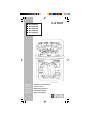 1
1
-
 2
2
-
 3
3
-
 4
4
-
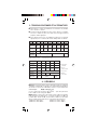 5
5
-
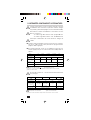 6
6
-
 7
7
-
 8
8
-
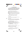 9
9
-
 10
10
-
 11
11
-
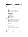 12
12
-
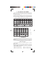 13
13
-
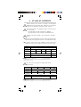 14
14
-
 15
15
-
 16
16
-
 17
17
-
 18
18
-
 19
19
-
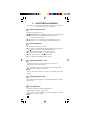 20
20
-
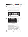 21
21
-
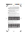 22
22
-
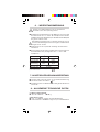 23
23
-
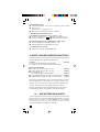 24
24
-
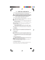 25
25
-
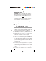 26
26
-
 27
27
-
 28
28
-
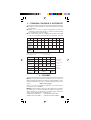 29
29
-
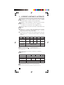 30
30
-
 31
31
-
 32
32
-
 33
33
-
 34
34
-
 35
35
-
 36
36
-
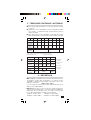 37
37
-
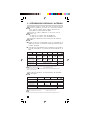 38
38
-
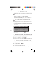 39
39
-
 40
40
-
 41
41
-
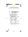 42
42
-
 43
43
-
 44
44


