Hampton Bay 23MM6072-C242 Instrucciones de operación
- Categoría
- Chimeneas
- Tipo
- Instrucciones de operación

ATTENTION
IF YOU HAVE ANY PROBLEMS OR QUESTIONS, EMAIL
OR CALL CUSTOMER SERVICE BEFORE YOU RETURN
THIS PRODUCT TO THE STORE WHERE IT WAS PURCHASED.
For Customer Service: email: par[email protected]
in English Call: 866-661-1218
in Spanish Call: 866-661-1218
in French Call: 866-374-9203
ATENCIÓN
SI TIENE ALGÚN PROBLEMA O PREGUNTAS,
ENVÍE UN MENSAJE DE CORREO ELECTRÓNICO O LLAME AL SERVICIO
DE ATENCIÓN AL CLIENTE ANTES DE DEVOLVER
ESTE PRODUCTO A LA TIENDA EN LA QUE LO COMPRÓ.
Servicio de atención al cliente: Correo electrónico: par[email protected]
Línea para llamadas en inglés: 866-661-1218
Línea para llamadas en español: 866-661-1218
Línea para llamadas en francés: 866-374-9203
STOP STOP
PARE PARE
ATTENTION
SI VOUS AVEZ DES PROBLÈMES OU QUESTIONS,
ENVOYEZ UN COURRIEL AU SERVICE À LA CLIENTÈLE OU APPELEZ LE
SERVICE À LA CLIENTÈLE AVANT DE RETOURNER
CE PRODUIT OÙ VOUS L’AVEZ ACHETÉ.
Pour le service à la clientèle : courriel : par[email protected]
pour le service en anglais, composez le 866-661-1218
pour le service en espagnol, composez le 866-661-1218
pour le service en français, composez le 866-374-9203
ARRÊT ARRÊT
INSTRUCTION MANUAL ENCLOSED
MANUEL D’INSTRUCTION À L’INTÉRIEUR
MANUAL DE INSTRUCCIONES ADJUNTO
INSTRUCTION MANUAL ENCLOSED
MANUEL D’INSTRUCTION À L’INTÉRIEUR
MANUAL DE INSTRUCCIONES ADJUNTO

1
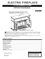
ELECTRIC FIREPLACE
73719/23MM6072VMA
INSTRUCTION MANUAL
E-mail: [email protected]
In English call: 866-661-1218
In French call: 866-374-9203
In Spanish call: 866-661-1218
For Customer Service:
Twin-Star International, Inc.
Delray Beach, FL 33445
Made in China
Printed in China
Español p.17
Important Information....................................................................................................................... 2
Product Specifi cations..................................................................................................................... 3
Package Contents........................................................................................................................... 4
Hardware Contents.......................................................................................................................... 5
Safety Information............................................................................................................................ 5
Preparaion ........................................................................................................................................ 6
Assembly Instruction........................................................................................................................ 6
Operating Instructions...................................................................................................................... 11
Care and Maintenance..................................................................................................................... 13
Troubleshooting............................................................................................................................... 14
Warranty.......................................................................................................................................... 15
Replacement Parts List................................................................................................................... 16
TABLE OF CONTENTS
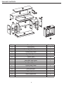
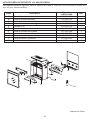
MAXIMUM LOAD 30 lb. (13.6kg)
CAUTION: This unit is intended for use only with the products and maximum weights
indicated. Use with other products or products heavier than the maximum weights
indicated may result in instability causing possible injury.
Note: Flat Panel TVs with base support should be placed squarely in the center of the
stand with no overhang on any side.
FIT UP TO 62” PLASMA/LCD TELEVISIONS
MAXIMUM LOAD 135 lb. (61.22 kg)

2
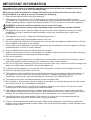
Please read and understand this entire manual before attempting to assemble, operate or install
the product. If you have any question regarding the product, please call customer service at
1-866-661-1218, 8 a.m.-8 p.m., EST, Monday-Friday.
When using electrical appliances, always follow basic precautions to reduce the risk of fi re,
electrical shock, and injury to persons including the following:
1. Read all instructions before using this appliance.
2. This appliance is hot when in use. To avoid burns, do not touch hot surfaces with bare skin.
If provided, use handles when moving this appliance. Keep combustible materials, such as furniture,
pillows, bedding, papers, clothes and curtains at least 3 ft. (0.9 m) from the front of this appliance.
WARNING: In order to avoid overheating, do not cover the heater.
WARNING: Use extreme caution when operating heater near children and the disabled.
3. The appliance is not to be used by children or persons with reduced physical, sensory or mental
capabilities, or lack of experience and knowledge, unless they have been given supervision
or instruction.
4. This appliance is not a toy. Supervise children playing near it.
5. If possible, always unplug this appliance when not in use.
6. Do not operate any heater with a damaged cord or plug, after the appliance malfunctions, or if it has
been dropped or damaged in any manner.
7. If the supply cord is damaged, it must be replaced by the manufacturer, its service agent or similarly
qualifi ed persons in order to avoid a hazard.
8. Only a qualifi ed service person should repair this product.
9. Under no circumstances should this fi replace be modifi ed. Parts having to be removed for servicing
must be replaced prior to operating this fi replace again.
10. Do not use outdoors.
11. This heater is not intended for use in bathrooms, laundry areas and similar indoor locations. Never
locate this appliance where it may fall into a bathtub or other water container.
12. Do not run cord under carpeting. Do not cover cord with throw rugs, runners or the like. Arrange cord
away from traffi c areas and where it will not be tripped over.
13. To disconnect this appliance, turn controls to the off position, and then remove plug from outlet.
14. Connect to properly grounded outlets only.
15. This appliance, when installed, must be electrically grounded in accordance with local codes or, in
the absence of local codes, with the current CSA C22.1 Canadian Electrical Code or for U.S.A.
installations, follow local codes and the National Electrical Code, ANSI/NFPA NO.70.
16. The heater must not be located immediately below a socket-outlet.
17. Do not insert or allow foreign objects to enter any ventilation or exhaust opening as this may cause
an electric shock or fi re, or damage the appliance.
18. To prevent a possible fi re, do not block air intakes or exhaust in any manner. Do not use on soft
surfaces, like a bed, where opening may become blocked.
19. This appliance has hot and arcing or sparking parts inside. Do not use it in areas where gasoline,
paint or fl ammable liquids are used or stored. This fi replace should not be used as a drying rack for
clothing. Do not hang Christmas stockings or other decorations on or near this product.
20. Use this appliance only as described in the manual. Any other use not recommended by the
manufacturer may cause fi re, electric shock or injury to persons.
21. There is a thermostat limiter inside the heater. When inner temperature overheating or abnormal
heating occurs, the thermostat protective device will cutoff the power supply to avoid damage to the
fi replace or risk of fi re.
IMPORTANT INFORMATION

3
B
A
CD
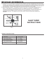
Grounding Pin
Fig. 1
IMPORTANT INFORMATION
Metal
Screws
Grounding
Means
SAVE THESE
INSTRUCTIONS
22. Avoid the use of an extension cord because the extension cord may overheat and cause risk of fi re.
However, if you have to use an extension cord, the cord must be No.14 AWG minimum size and rated
not less than 1875 watts. The extension cord must be a three-wire cord with grounding type plug and
cord connection. The extension cord shall not be more than 20 ft. (6 m) in length.
23. See directions in Figure 1. This heater is for use on 120 volts. The cord has a plug as shown in
figure 1. See Figure 1 for grounding instruction. An adapter as shown at C is available for
connecting three-blade grounding type plugs to two-slot receptacles. The green grounding plug
extending from the adapter must be connected to a permanet ground such as a properly
gounnded outlet box. The adapter should not be used if a three-slot grounded receptacle is
available.
PRODUCT SPECIFICATIONS
VOLTAGE 120 V, 60 Hz
AMPS (with heater) 11.7 Amps
AMPS (without heater) < 0.1 Amps
WATTS (with heater) 1400 Watts
WATTS (without heater) < 10 Watts

4
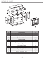
PACKAGE CONTENTS
Part Description Quantity
A Hearth/Base 1
B Center Left Front Panel 1
C Center Right Front Panel 1
D Center Front Panel 1
E Left Side Panel 1
F Right Side Panel 1
G Center Shelf 1
H Center Upper Front Panel 1
I Left Upper Side Panel 1
J Right Upper Side Panel 1
K Mantel/Top 1
L Center Back Panel 1
M Side Back Panel 2
N Left Front Door 1
O Right Front Door 1
P Wood Shelf 2
Q Insert Support Bar 1
R Insert 1
G
D
Q
B
A
R
EP
C
F
K
M
M
P
O
N
LH
I
J

5
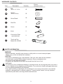
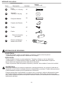
HARDWARE CONTENTS
Part Description Quantity
Picture
(Shown to size)
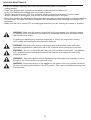
SAFETY INFORMATION
WARNING
• Before assembly, carefully use scissors or utility knife to cut and unwrap all parts.
Make sure you do not discard the hardware.
CAUTION
• Use care in assembling your new fireplace. Take your time and use the hardware
provided and a quality Phillips head screwdriver. Never overtighten bolts.
• Do not sit on any part of the mantel.
• All panels are labeled left and right as viewed from the front of unit.
WARNING
To avoid injury from unexpected starting or electrical shock, do not plug the power cord into a
source of power during unpacking and assembly. The cord must remain unplugged whenever
you are adjusting/assembling the fi replace.
If any part is missing or damaged, do not attempt to use or plug in the power cord until the
missing or damaged part is correctly replaced. To avoid electric shock, use only identical
replacement parts when servicing double-insulated tools.
Bolt
1/4 in. x 1-1/4 in.
Washer
1/4 in. x 3/4 in.
Wood Dowel
Shelf Pin
Screw
Knob
Connection Plate
(pre-attached)
30
30
34
8
43
2
6
BB
CC
DD
EE
FF
GG
AA
Touch-up Pen
Model No. W3348 1
ZZ
W3348

6
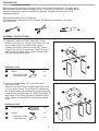
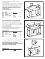
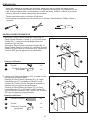
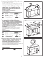
1. Locate the Center Left Front Panel (B), Center
Right Front Panel (C), Center Front Panel (D), and
set out face down on a scratch-free surface.
Connect the Center Left Front Panel (B), Center
Right Front Panel (C) and Center Front Panel (D)
with Connection Plate (GG), tighten Screws (EE)
through the pre-drilled holes.
ASSEMBLY INSTRUCTIONS
PREPARATION
Before beginning assembly of product, make sure all parts are present. Compare parts
with package contents list and diagram above. If any part is missing or damaged, do not
attempt to assemble, install or operate the product. Contact customer service for
replacement parts.
Estimated Assembly Time: 60 Minutes
Tools Required for Assembly (not included): Phillips head screwdriver, scissors
and utility knife
Fig. 2
2. Insert one Wood Dowel (CC) into each of the
pre-drilled holes.
Push the Left Side Panel (E) and Right Side Panel
(F) snug to the Center Front Panel (D). Make sure
the Wood Dowels are seated in the pre-drilled holes.
Connect the Left Side Panel (E), Right Side Panel (F)
and Center Front Panel (D) with Connection Plate
(GG), tighten Screws (EE) through the pre-drilled
holes.
Hardware Used
Hardware Used
GG
GG
EE
CC
EE
CC
CC
Screw
Wood Dowel
Screw
x 2
x 4
x 2
Connection Plate
(pre-attached)
Connection Plate
(pre-attached)
x 2
x 2
Fig. 1
E
EE
EE
D
B
C
F
GG
GG

7
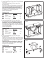
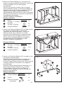
Fig. 3
Fig. 4
Fig. 5
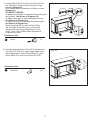
3. Locate Hearth/Base (A) and set out finished side up
on the floor.
Insert one Wood Dowel (CC) into each of the
pre-drilled holes.
Using two (2) persons lift and attach the completed
front assembly from step 2 to the Hearth/Base (A).
Make sure that Wood Dowels (CC) are seated into
the pre-drilled holes in the hearth/base. Using
Bolt (AA) and Washer (BB) attach panels through
pre-drilled holes in the mounting blocks.
HAND TIGHTEN ONLY.
Hardware Used
Hardware Used
Hardware Used
BB
BB
AA
AA
CC
CC
CC
Bolt
1/4 in. x 1-1/4 in.
Bolt
1/4 in. x 1-1/4 in.
x 8
Washer
1/4 in. x 3/4 in.
Washer
1/4 in. x 3/4 in.
x 8
Wood Dowel
Wood Dowel
Wood Dowel
x 8
x 4
4. Insert one Wood Dowel (CC) into each of the
pre-drilled holes on the top edges of the Assembly
from step 3. Then locate Center Shelf (G) and lay
fi nished side up on top of completed assembly.
From the inside, attach Center Shelf (G) using Bolt
(AA) and Washer (BB) through the pre-drilled holes
in the mounting blocks.
HAND TIGHTEN ONLY.
5. Insert one Wood Dowel (CC) into each of the
pre-drilled holes.
Push the Left Upper Side Panel (I) and Right Upper
Side Panel (J) snug to the Center Upper Front Panel
(H). Make sure the Wood Dowels are seated in the
pre-drilled holes.
Connect the Left Upper Side Panel (I), Right Upper
Side Panel (J) and Center Upper Front Panel (H)
with Connection Plate (GG), tighten Screws (EE)
through the pre-drilled holes.
CC A
BB
AA
G
x 10
x 10
x 9
BB
AA
CC
CC
J
H
I
EE
GG
CC
CC
EE
GG
Screw
Connection Plate
(pre-attached)
x 2
x 2

8
Fig. 8
Hardware Used
Hardware Used
BB
AA
CC
Bolt
1/4 in. x 1-1/4 in. x 6
Washer
1/4 in. x 3/4 in. x 6
Wood Dowel x 5
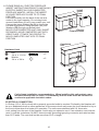
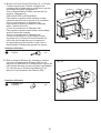
7. Insert one Wood Dowel (CC) into each of the
pre-drilled holes on the top edges of the Assembly
from step 6. Then locate Mantel/Top (K) and lay
fi nished side up on top of completed assembly.
From the inside, attach Mantel/Top (K) using Bolt
(AA) and Washer (BB) through the pre-drilled holes
in the mounting blocks.
HAND TIGHTEN ONLY.
Using Phillips head screwdriver tighten all Bolts
alternating top and bottom, left and right.
8. Locate Back Panel (M) and Center Back Panel (L),
attach to the back of the completed assembly from
step 7. Use a Phillips Head screwdriver, tighten
screws (EE) through the pre-drilled holes in the
Back Panels to the completed assembly.
Then use a Phillips Head Screwdriver to tighten the
bolts that were left hand tightened.
BB
L
M
M
EE
EE
K
AA
CC
CC
Fig. 6
Fig. 7
6. Insert one Wood Dowel (CC) into each of the
pre-drilled holes.
Using two (2) persons lift and attach the completed
front assembly from step 5 to the Center Shelf (G)
as shown in diagram. Make sure that Wood Dowels
(CC) are seated into the pre-drilled holes in the
hearth/base. Using Bolt (AA) and Washer (BB)
attach panels through pre-drilled holes in the
mounting blocks.
HAND TIGHTEN ONLY.
Hardware Used
BB
AA
CC
Bolt
1/4 in. x 1-1/4 in. x 4
Washer
1/4 in. x 3/4 in. x 4
Wood Dowel x 4
CC
CC
G
BB
AA
EE Screw x 37

9
Fig. 9
Fig. 10
N
O
DD
P
FF
9. Locate Right Front Door (O) and Left Front Door
(N). Slide door hinge keyhole into panel hinge
bracket. (Diagram 1)
Use Phillips Head Screwdriver to tighten screws.
(Diagram 2)
TO ADJUST HINGES
To adjust door forward or backward change keyhole
slot position. (As Shown In Diagram 3a)
To adjust door right or left loosen/tighten screw.
(As Shown In Diagram 3b)
To adjust door up or down adjust bracket height.
(As Shown In Diagram 3c)
Attach the Knob (FF) to the Left Front Door
(N) and Right Front Door (O), use the bolts
attached through the pre-drilled holes in the
doors. Then use a Phillips Head Screwdriver
to tighten the bolts.
10. Choose desired height of Shelf (P) and place the
four Shelf Pin (DD) into same height shelf holes
inside side panels. Insert Wood Shelf (P), allow
Wood Shelf (P) to rest on the Shelf Pin (DD).
Hardware Used
DD Shelf Pin x 8
Hardware Used
FF Knob x 2

10
ELECTRICAL CONNECTION
A 15-Amp, 120-V, 60 Hz circuit with a properly grounded outlet is required. Preferably, the fi replace will
be on a dedicated circuit as other appliances on the same circuit may cause the circuit breaker to trip or
the fuse to blow when the heater is in operation. The unit comes standard with 6-ft. three-wire
cord, exiting from the rear of the fi replace. Avoid using an extension cord. If an extension cord must be
used, it must be a minimum 14 AWG, three wire with grounding type plug connector and rated not less
than 1875 watts. The cord shall not be more than 20 ft. in length.
Cold climate installation recommendation: When installing this unit against a non-
insulated exterior wall or chase, it is mandatory that the outer walls be insulated to
conform to applicable insulation codes.
Fig. 11
Install
Insert
From
Back
Completed
Unit
Electric
Fireplace Insert
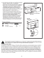
11. PLEASE READ ALL “ELECTRIC FIREPLACE
INSERT” INSTRUCTIONS PRIOR TO INSTALLING
ELECTRIC INSERT IN YOUR COMPLETED
FIREPLACE MANTEL. INSTALL THE INSERT
IN YOUR FIREPLACE CLOSE TO ITS FINAL
POSITION.
Lift insert carefully into the back of the unit and
center in the insert opening. Do not drag insert
across Hearth/Base (A) as it may scratch your unit.
Connect the Insert Support Bar (Q) to the inside
Left and Right panels, using the Bolts (AA) and
Washers (BB) through pre-drilled holes.
MOVE YOUR COMPLETED UNIT ONLY SHORT
DISTANCES. MOVE COMPLETED UNIT WITH
GREAT CARE. IT TAKES TWO PEOPLE TO
MOVE COMPLETED UNIT INTO ITS FINAL
POSITION.
Q
AA BB
Hardware Used
BB
AA Bolt
1/4 in. x 1-1/4 in. x 2
Washer
1/4 in. x 3/4 in. x 2

11
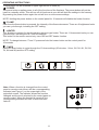
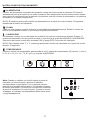
Note: When a function is changed from the control
panel or remote control there will be a corresponding
indicator (see Figure 1) on the upper-right of the
projection screen. The indicator shows the function
changed and the level selected by the control panel or
remote control. When the function is turned off, the
corresponding indicator will fl ash 5 times and then
fade off.
°
°
C
F
Fig . 1
OPERATING INSTRUCTIONS
Control panel can be accessed at upper-right corner of insert (R).
- POWER
The power button supplies power to all of the functions of the fi replace. The power button will put the
insert in a standby mode. This will turn off all functions at once but will hold the settings in the memory.
By pressing the power button again the unit will turn on at the same settings.
NOTE: Holding the power button on the control panel for 10 seconds will disable the heater function.
- FLAME
Each time the fl ame button is pressed, the intensity of the fl ame decreases. There are 6 brightness levels
you can cycle through, including the OFF setting.
- HEATER
Your fi replace consists of a fan-forced wire-element-type heater. There are 11 thermostat levels you can
cycle through, including the OFF and ON settings.
This button on the remote control only turns ON and OFF heater function.
NOTE: To change between °F and °C press and hold the heater button on the control panel for
10 seconds.
- TIMER
Press the timer button to cycle through the 10 timer settings (30 minutes, 1 Hour, 2H, 3H, 4H, 5H, 6H,
7H, 8H and 9H) and the OFF setting.

12
NOTE: This equipment has been tested and found to comply with the limits for Class B digital device,
pursuant to part 15 of the FCC Rules. These limits are designed to provide reasonable protection against
harmful interference in a residential installation. This equipment generates, uses, and can radiate radio
frequency energy and, if not installed and used in accordance with the instructions, may cause harmful
interference to radio or television reception, which can be determined by turning the equipment off and
on, the user is encouraged to try to correct the interference by one or more of the
following measures:
• Reorient or relocate the receiving antenna.
• Increase the separation between the equipment and the receiver.
• Connect the equipment into an outlet on a circuit different from that to which the receiver is connected.
• Consult the dealer or an experienced radio/TV technician for help.
This device complies with Part 15 of the FCC Rules. Operation is subject to the
following two conditions:
(1) This device may not cause harmful interference, and
(2) this device must accept any interference received, including interference that may cause undesired
operation.
Modifi cations not approved by the party responsible for compliance could void user’s authority to operate
the equipment.
This Class B digital apparatus complies with Canadian ICES-003.
REPLACING THE REMOTE CONTROL BATTERY
When the remote control stops operating or its range seems reduced, it is time to replace the battery with
new ones. Note: Batteries should be removed if the product is to be left unused for a long time.
1. The battery compartment is located on the back end of the remote.
2. Press and slide the battery door open and remove the old battery.
3. Insert 2 AAA batteries (not included), checking that the + and - sides of the battery match inside the
battery compartment.
4. Replace the battery compartment door.
DISPOSAL OF USED BATTERIES
Battery may contain hazardous substances which could be endangering to
enviroment and human health.
This symbol marked on the battery and/or packaging indicates that used battery shall
not be treated as municipal waste. Instead it shall be left at the appropriate collection
point for recycling.
By ensuring the used batteries are disposed of correctly, you will help preventing
potential negative consequences for the environment and human health. The recycling
of materials will help to converse natural resources.
For more information about collection and recycling of used batteries, please contact
your local municipality, your waste disposal service or the point of sale where you
purchased this point.
NOTE: PLEASE OPERATE REMOTE TRANSMITTER AT A SLOW MEASURED PACE. PRESS THE
REMOTE CONTROL BUTTONS WITH AN EVEN MOTION AND GENTLE PRESSURE. REPEATEDLY
PRESSING BUTTONS IN RAPID SUCCESSION MAY CAUSE THE TRANSMITTER TO
MALFUNCTION.

13
WARNING: Make sure the power is turned off before proceeding. Any electrical repairs
or rewiring of this unit should be carried out by a licensed electrician in accordance with
national and local codes.
If repairing or replacing any electrical component or wiring, the original wire routing,
color coding and securing locations must be followed.
• The motors used on the fan and the fl ame generator assembly are pre-lubricated for extended bearing
life and require no further lubrication. However, we recommend periodic cleaning/vacuuming of the
fan/heater.
• Make sure the unit is turned OFF and unplugged whenever you are cleaning the heater or fi replace.
WARNING: Electrical outlet wiring must comply with local building codes and other
applicable regulations to reduce the risk of fi re, electrical shock and injury to persons.
WARNING: Do not use this fi replace if any part of it has been under water. Immediately
call a qualifi ed service technician to inspect the fi replace and replace any part of the
electrical system.
WARNING: Disconnect power before attempting any maintenance or cleaning to reduce
the risk of fi re, electrical shock or personal injury.
WARNING: During any service of this appliance, the power to the unit must be turned off.
First turn the main power switch to the OFF position. Then remove the electrical plug from
the wall outlet.
CARE AND MAINTENANCE
• Dust your fi replace regularly with a soft non-lint producing cloth or household
dusting product.
• Clean your fi replace with a gentle non-abrasive household cleaner. Make sure
to dry your fi replace immediately with a soft cloth or towel.
• Tips for using touch-up pen (ZZ): For scratches, stroke in direction of scratch. For worn areas,
stroke in direction of wood grain. Rub excess colorant promptly with a soft cloth.

14
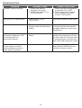
TROUBLESHOOTING
PROBLEM POSSIBLE CAUSE CORRECTIVE ACTION
No power, logs do not glow. 1. Power cord was not
plugged in the outlet.
2. Main power switch is not
in “ON” position.
1. Check that unit is plugged into
a standard 120V outlet.
2. Press power button several
times, making sure power
is set at “ON” position.
Logs glow, but no fl ame effect. Flame button is not in
“ON” position. Press fl ame button several times.
Heater does not blow warm air. The current room temperature
is higher than the temperature
setting.
Adjust the temperature settings
to ensure that the thermostat is
set higher than the current room
temperature.
Heater doesn’t work, but Power
and Heater settings are “ON”
and thermostat is set
(see solution above).
The product is on protected
status. Turn all switches to the “OFF”
position and unplug the unit from
the wall outlet for 5 minutes. After
5 minutes plug the unit back into
wall outlet, and operate as normal.
Flame effect works but heater
function does not and the
emberbed fl ashes when the
heater button is pressed.
Heater function is locked. Heater function is locked. Press
and hold the POWER button to
unlock the heater function.

15
1-YEAR LIMITED WARRANTY
The manufacturer warrants this product to be free from manufacturing and material defects for a period of
one year from date of purchase, subject to the following conditions and limitations.
1. Install and operate this Electric Fireplace in accordance with the installation and operating
instructions furnished with the product at all times. Any unauthorized repair, alteration, willful abuse,
accident, or misuse of the product shall nullify this warranty.
2. This warranty is non-transferable, and is made to the original owner, provided that the purchase was
made through an authorized supplier of the product.
3. The warranty is limited to the repair or replacement of part(s) found to be defective in material or
workmanship, provided that such part(s) have been subjected to normal conditions of use and
service, after said defect is confi rmed by the manufacturer’s inspection.
4. The manufacturer may, at its discretion, fully discharge all obligations with respect to this warranty by
refunding the wholesale price of the defective part(s).
5. Any installation, labor, construction, transportation, or other related costs/expenses arising from
defective part(s), repair, replacement, or otherwise of same, will not be covered by this warranty,
nor shall the manufacturer assume responsibility for same.
6. The owner/user assumes all other risks, if any, including the risk of any direct, indirect or
consequential loss or damage arising out of the use, or inability to use the product, except
as provided by law.
7. All other warranties – expressed or implied – with respect to the product, its components and
accessories, or any obligations/liabilities on the part of the manufacturer are hereby expressly
excluded.
8. The manufacturer neither assumes, nor authorizes any third party to assume on its behalf, any other
liabilities with respect to the sale of the product.
9. The warranties as outlined within this document do not apply to non accessories used in conjunction
with the installation of this product.
This warranty is void if:
a. The fi replace is subjected to prolonged periods of dampness or condensation.
b. Any unauthorized alteration, willful abuse, accident, or misuse of the product.
c. You do not have the original receipt of purchase.
IF WARRANTY SERVICE IS NEEDED
Contact the manufacturer by calling customer service department at 1-866-661-1218,
8 a.m.-8 p.m., EST, Monday-Friday. Make sure you have your warranty, your sales receipt,
location of purchase and the model/serial number of your product.

16
Printed in China
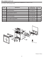
REPLACEMENT PARTS LIST
For replacement parts, call our customer service department at 1-866-661-1218,
8 a.m.-8 p.m., EST, Monday-Friday.
Part Description Part No.
23EF023GRA Qty
A Heater/Blower Assembly Y07-C26-P01 1
B Main Circuit Board Y11-C53-P15 1
C Flame Generator Drive Motor Y07-P10Q 1
D Flame Generator/ Spinner Y10-S52-P011 1
E LCD Display Y10-C43-P70 1
F Front Projection Screen Y10-S52-P09 1
G Flame Circuit Board Y11-C53-P40 1
H Emberbed with log Y10-S52-P02 1
I Control Panel Circuit Board Y10-S52-P32 1
J Control Panel - 4 Buttons Y10-C43-P25 1
K Remote Control - 4 Buttons P71 1
REMOTE/REMOTO/
TÉLÉCOMMANDE
A
K
BC
D
E
F
G
H
I
J

17
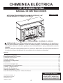
73719/23MM6072VMA
CHIMENEA ELÉCTRICA
MANUAL DE INSTRUCCIONES
English p.1
Twin-Star International, Inc.
Delray Beach, FL 33445
Fabricado en China
Impreso en China
Correo: [email protected]
En inglés llame al: 866-661-1218
En francés llame al: 866-374-9203
En español llame al: 866-661-1218
Servicio al cliente:
ÍNDICE
Información Importante .......................................................................................................................18
Especifi caciones Del Producto ............................................................................................................19
Contenido Del Paquete .......................................................................................................................20
Herrajes Incluidos ................................................................................................................................21
Información De Seguridad ...................................................................................................................21
Preparación .........................................................................................................................................22
Instrucciones De Montaje ................................................................................................................... 2 2
Instrucciones De Funcionamiento .......................................................................................................27
Cuidado Y Mantenimiento ...................................................................................................................29
Solución De Problemas .......................................................................................................................30
Garantía Limitada De 1 Año ................................................................................................................31
Lista De Piezas De Repuesto Y Plano De Piezas ...............................................................................32
APTO PARA TELEVISORES DE PLASMA O LCD DE 42” a 62”
CARGA MÁXIMA: 135 LIBRAS (61.22 KILOS)
CARGA MÁXIMA: 30 LIBRAS (13.6 KILOS)
PRECAUCIÓN: Esta unidad está diseñada para ser usada únicamente con los productos y
con los pesos máximos indicados. El uso con otros productos, o con productos de peso mayor
a los pesos máximos indicados, puede producir inestabilidad, lo que posiblemente causaría
lesiones.
Nota: Los televisores de pantalla plana con soporte de base deben colocarse perfectamente en
el centro de la base del gabinete, sin que ninguno de los laterales sobresalga.

18
Lea y comprenda completamente este manual antes de intentar ensamblar, usar o instalar el producto.
Si tiene alguna pregunta sobre el producto, comuníquese con Servicio al Cliente al 1-866-661-1218, de
lunes a viernes, de 9 a.m. a 5 p.m. (hora estándar del Este).
Cuando utilice electrodomésticos, siempre tome medidas de precaución básicas para evitar incendios,
descargas eléctricas y lesiones personales. Entre ellas:
1. Lea todas las instrucciones antes de usar este electrodoméstico.
2. Este electrodoméstico se calienta cuando está en funcionamiento. Para evitar quemaduras, no
toque superfi cies calientes con la piel descubierta. Si se incluyen, utilice las manijas para trasladar
el electrodoméstico. Mantenga materiales infl amables, como muebles, almohadas, ropa de cama,
papeles, ropa y cortinas al menos a 91,44 cm (3 pies) de la parte delantera de este
electrodoméstico.
ADVERTENCIA: Para evitar el sobrecalentamiento, no cubra el calentador
ADVERTENCIA: Tenga extrema precaución cuando utilice el calentador cerca de niños y de
personas discapacitadas.
3. Este electrodoméstico no debe ser usado por personas o niños con capacidades físicas, sensoria
les o mentales reducidas o sin experiencia ni conocimientos, a menos que una persona
responsable de su seguridad les brinde supervisión o capacitación respecto al uso del
electrodoméstico.
4. Este electrodoméstico no es un juguete. Supervise a los niños que juegan cerca.
5. Si es posible, siempre desenchufe este electrodoméstico cuando no lo use.
6. No opere ningún calentador con un cable o enchufe dañados, después de fallas del mismo, de que
se haya dejado caer o dañado de cualquier forma.
7. Si el cable de alimentación está dañado, el fabricante, su empresa de servicio o alguien de
califi cación similar deben reemplazarlo para evitar peligros.
8. Sólo un técnico califi cado debe reparar este producto.
9. Bajo ninguna circunstancia se debe modifi car esta chimenea. Las piezas que se deben retirar para
reparación se deben reemplazar antes de volver a hacer funcionar esta chimenea.
10. No lo use en exteriores.
11. Este calentador no se debe usar en el baño, lavadero y en espacios húmedos similares inte riores.
Nunca coloque este calentador donde se pueda caer dentro de una bañera u otro contenedor de
agua.
12. No coloque el cable debajo de una alfombra. No cubra el cable con alfombras, tapetes o similares.
Coloque el cable lejos de zonas de tránsito en donde nadie se pueda tropezar y caer.
13. Para desconectar este electrodoméstico, gire los controles a la posición de apagado y luego retire
el enchufe del tomacorriente.
14. Conecte sólo a tomacorrientes con la debida puesta a tierra.
15. Cuando está instalado, este artefacto debe presentar una conexión eléctrica a tierra según los
códigos locales, según los Códigos de Electricidad de Canadá CSA C22.1 o, para instalaciones en
EE.UU., siga los códigos locales y el código nacional de electricidad, ANSI/NFPA No. 70.
16. No debe colocar el calentador inmediatamente debajo de un tomacorriente fi jo.
17. No introduzca objetos extraños ni permita que entren en las aberturas de ventilación o escape, ya
que pueden provocar descargas eléctricas, incendios o daños en el electrodoméstico.
18. Para evitar incendios, no bloquee las entradas ni salidas de aire de ninguna manera. No use sobre
superfi cies blandas, como una cama, donde las aberturas se puedan bloquear.
19. Este electrodoméstico tiene en su interior piezas calientes y piezas que forman arcos eléctricos o
que echan chispas. No lo use en áreas donde se use o almacene gasolina, pintura o líquidos
infl amables. Esta chimenea no se debe usar como una rejilla para secar ropa. No cuelgue medias
navideñas u otras decoraciones sobre o cerca de este producto.
20. Utilice este electrodoméstico sólo como se describe en este manual. Cualquier otro uso no
recomendado por el fabricante puede causar incendios, descargas eléctricas o lesiones personales.
21. Hay un limitador del termostato dentro del calentador. Cuando ocurre un sobrecalentamiento de la
temperatura interna o un calentamiento anormal, el dispositivo protector del termostato cortará la
alimentación de energía para evitar un daño en la chimenea o un riesgo de incendio.
INFORMACIÓN IMPORTANTE

19
ESPECIFICACIONES DEL PRODUCTO
VOLTAJE 120 V, 60 Hz
AMPERAJE (con calentador) 11,7 amperios
AMPERAJE (sin calentador) < 0,1 amperios
VATAJE (con calentador) 1400 vatios
VATAJE (sin calentador) < 10 vatios
INFORMACIÓN IMPORTANTE
22. Evite utilizar una extensión eléctrica porque se puede sobrecalentar y provocar un incendio. Sin
embargo, si tiene que usar un cable de extensión, debe ser de tamaño mínimo AWG No.14 y tener
una clasifi cación de 1875 vatios cómo mínimo. La extensión eléctrica debe ser un cable de tres
conductores con enchufe con puesta a tierra y un conector para cable. La extensión eléctrica no
debe tener más de 6,10 m (20 pies) de largo.
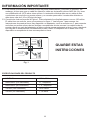
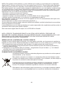
23. Consulte las instrucciones en la Figura 1. Este calentador fue diseñado para su uso en 120 voltios.
El cable tiene un enchufe, como se muestra en la fi gura 1. Vea la fi gura 1 para conocer las
instrucciones de puesta a tierra. Hay disponible un adaptador, como se muestra en C, para conectar
enchufes con puesta a tierra de tres clavijas a receptáculos de dos ranuras. La orejeta verde de
puesta a tierra que sale del adaptador se debe conectar permanentemente a tierra, como a través de
una caja de un tomacorriente correctamente puesto a tierra. El adaptador no se debe usar si hay
disponible un receptáculo de tres ranuras puesto a tierra.
B
A
CD
Fig. 1
Clavija con
puesta a tierra
Tornillos
para metal
Medios de
puesta a tierra
GUARDE ESTAS
INSTRUCCIONES

20
Pieza Descripción Cantidad
A Chimenea/Base 1
B Panel Frontal Izquierdo Central 1
C Panel Frontal Derecho Central 1
D Panel Frontal Central 1
E Panel Lateral Izquierdo 1
F Panel Lateral Derecho 1
G Estante Central 1
H Panel Frontal Superior Central 1
I Panel Lateral Superior Izquierdo 1
J Panel Lateral Superior Derecho 1
K Chimenea/Repisa 1
L Panel Posterior Central 1
M Panel Posterior Lateral 2
N Puerta Frontal Izquierda 1
O Puerta Frontal Derecha 1
P Estante de Madera 2
Q Barra de Soporte del Inserto 1
R Inserto 1
G
D
Q
B
A
R
EP
C
F
K
M
M
P
O
N
LH
I
J
CONTENIDO DEL PAQUETE

21
Pasador del Estante
Tornillo
Perilla
Placa de Conexión
(pre-fi jada)
30
30
34
8
43
2
6
BB
CC
DD
EE
FF
GG
AA
Plumón de Retoque
Modelo No.W3348 1
ZZ
W3348
HERRAJES INCLUIDOS
Parte Descripción Cantidad
Imagen
(Tamaño real)
Perno
1/4 pulg. x 1-1/4 pulg.
Arandela
1/4 pulg. x 3/4 pulg.
Clavija de Madera
INFORMACIÓN DE SEGURIDAD
ADVERTENCIA
• Antes del montaje, corte con unas tijeras o un bisturí y desenvuelva las piezas
cuidadosamente. Asegúrese de no desechar los herrajes.
PRECAUCIÓN
• Tenga cuidado al armar su nueva chimenea. Tómese su tiempo y use los elementos
suministrados y un destornillador Phillips de calidad. No apriete demasiado los pernos.
• No se siente en ninguna parte de la repisa de la chimenea.
• Todos los paneles están etiquetados izquierda y derecha, vistos desde el frente de la unidad.
ADVERTENCIA
Para evitar lesiones por arranque inesperado o descarga eléctrica, no conecte el cable de ali-
mentación a una fuente de energía durante el desembalaje y montaje. El cable debe permanec-
er desconectado siempre que se ajuste/arme la chimenea.
Si alguna pieza falta o está dañada, no intente usar o conectar el cable de alimentación hasta
que la pieza dañada o faltante sea sustituida correctamente. Para evitar una descarga eléc-
trica, utilice únicamente piezas de repuesto idénticas cuando dé mantenimiento a herramientas
doblemente aisladas.

22
1. Busque el Panel Frontal Izquierdo Central (B), el
Panel Frontal Derecho Central (C), el Panel Frontal
Central (D), y colóquelos boca abajo sobre una
superfi cie que no raye.
Conecte el Panel Frontal Izquierdo Central (B), el
Panel Frontal Derecho Central (C) y el Panel Frontal
Central (D) con Placa de Conexión (GG), apriete los
Tornillos (EE) por los agujeros pre-perforados.
Fig. 2
2. Inserte una Clavija de Madera (CC) en cada uno de
los agujeros pre-perforados.
Empuje el Panel Lateral Izquierdo (E) y el Panel
Lateral Derecho (F) ajustados al Panel Frontal
Central (D). Revise que las clavijas de madera se
asienten en los agujeros pre-perforados.
Conecte el Panel Lateral Izquierdo (E), el Panel
Lateral Derecho (F) y el Panel Frontal Central (D)
con la Placa de Conexión (GG), apriete los Tornillos
(EE) por los agujeros pre-perforados.
Herrajes utilizados
Herrajes utilizados
GG
GG
EE
CC
EE
CC
CC
Tornillo
Clavija de Madera
Tornillo
x 2
x 4
x 2
Placa de Conexión
(pre-fi jada)
Placa de Conexión
(pre-fi jada)
x 2
x 2
Fig. 1
E
EE
EE
D
B
C
F
GG
GG
PREPARACIÓN
Antes de empezar el montaje del producto, asegúrese de que todas las partes estén
presentes. Compare las piezas con la lista de empaque del paquete y el diagrama de ar-
riba. Si alguna pieza falta o está dañada, no trate de armar, instalar o utilizar el producto.
Llame a servicio al cliente para piezas de repuesto.
Tiempo estimado para el montaje: 60 Minutos
Herramientas necesarias para el armado (no incluidas): Destornillador Phillips, tijeras y
un bisturí.
INSTRUCCIONES DE MONTAJE

23
Fig. 3
Fig. 4
Fig. 5
3. Busque la Chimenea/Base (A) y colóquela en el
suelo con el lado terminado hacia arriba. Inserte una
Clavija de Madera (CC) en cada agujero
pre-perforado.
Con dos (2) personas, levante y fi je el conjunto
frontal terminado del paso 2 a la Chimenea/Base (A).
Asegúrese de que las Clavijas de Madera (CC) se
asienten en los agujeros pre-perforados en la
Chimenea/Base. Utilizando Pernos (AA) y Arandelas
(BB) fi je los paneles por los agujeros pre-perforados
en los bloques de montaje.
APRIETE A MANO SOLAMENTE
Herrajes utilizados
Herrajes utilizados
BB
BB
AA
AA
CC
CC
Perno
1/4 pulg. x 1-1/4 pulg.
Perno
1/4 pulg. x 1-1/4 pulg.
x 8
x 10
Arandela
1/4 pulg. x 3/4 pulg.
Arandela
1/4 pulg. x 3/4 pulg.
x 8
x 10
Clavija de Madera
Clavija de Madera
x 8
x 9
4. Inserte una Clavija de Madera (CC) en cada uno de
los agujeros pre-perforados en los bordes
superiores del conjunto del paso 3. Busque el
Estante Central (G) y colóquelo con el lado
terminado hacia arriba sobre el conjunto armado.
Desde el interior, fi je el Estante Central (G) con
Pernos (AA) y Arandelas (BB) por los agujeros
pre-perforados de los bloques de montaje.
APRIETE A MANO SOLAMENTE
5. Inserte una Clavija de Madera (CC) en cada uno de
los agujeros pre-perforados.
Empuje el Panel Lateral Superior Izquierdo (I) el
Panel Lateral Superior Derecho (J) ajustados
al Panel Frontal Superior Central (H). Revise que las
Clavijas de Madera se asienten en los agujeros
pre-perforados.
Conecte el Panel Lateral Superior Izquierdo (I), el
Panel Lateral Superior Derecho (J) y el Panel
Frontal Superior Central (H) con la Placa de
Conexión (GG), apriete los Tornillos (EE) por los
agujeros pre-perforados.
CC A
BB
AA
G
BB
AA
CC
CC
J
H
I
EE
GG
CC
CC
Herrajes utilizados
GG
CC
EE
Clavija de Madera
Tornillo
x 4
x 2
Placa de Conexión
(pre-fi jada) x 2

24
Fig. 8
Herrajes utilizados
7. Inserte una Clavija de Madera (CC) en los agujeros
pre-perforados en los bordes superiores del
conjunto del paso 6. Busque la Chimenea/Repisa
(K) y fíjela con el lado terminado hacia arriba sobre
el conjunto armado. Desde el interior, fi je la
Chimenea/Repisa (K) con Pernos (AA) y Arandelas
(BB) por los agujeros pre-perforados de los bloques
de montaje.
APRIETE A MANO SOLAMENTE
Con un destornillador Phillips apriete todos los
pernos alternando arriba y abajo, izquierda y
derecha.
8. Busque el Panel Posterior Lateral (M) y el Panel
Posterior Central (L), fi je a la parte posterior del
conjunto terminado en el paso 7. Utilice un
destornillador Phillips, apriete los Tornillos (EE) a
través de los agujeros pre-perforados en los
paneles posteriores al conjunto terminado.
Luego, use un destornillador Phillips para apretar los
pernos que se dejaron apretados a mano.
BB
L
M
M
EE
EE
K
AA
CC
CC
Fig. 6
Fig. 7
6. Inserte una Clavija de Madera (CC) en cada uno de
los agujeros pre-perforados.
Usando dos (2) personas levante y fi je el conjunto
frontal terminado del paso 5 al Estante Central (G)
como se muestra en el diagrama. Asegúrese de que
las Clavija de Madera (CC) estén asentadas en los
agujeros pre-perforados en la Chimenea/Base.
Usando Pernos (AA) y Arandelas (BB) fi je los
paneles por los agujeros pre-perforados en los
bloques de montaje.
APRIETE A MANO SOLAMENTE
CC
CC
G
BB
AA
EE Tornillo x 37
Herrajes utilizados
Herrajes utilizados
BB
BB
AA
AA
CC
CC
Perno
1/4 pulg. x 1-1/4 pulg.
Perno
1/4 pulg. x 1-1/4 pulg.
x 4
x 6
Arandela
1/4 pulg. x 3/4 pulg.
Arandela
1/4 pulg. x 3/4 pulg.
x 4
x 6
Clavija de Madera
Clavija de Madera
x 4
x 5

25
Fig. 9
Fig. 10
N
O
DD
P
FF
9. Busque la Puerta Frontal Derecha (O) y la Puerta
Frontal Izquierda (N). Deslice el agujero de
cerradura de la bisagra de la puerta en el soporte
de bisagra del panel. (Diagrama 1).
Use un destornillador Phillips para apretar los
tornillos. (Diagrama 2)
PARA AJUSTAR LAS BISAGRAS
Para ajustar la puerta hacia adelante o atrás,
cambie la posición de la ranura de la cerradura.
(Como se muestra en el Diagrama 3a)
Para ajustar la puerta a derecha o izquierda,
afl oje / apriete el tornillo.
(Como se muestra en el Diagrama 3b)
Para ajustar la puerta hacia arriba o hacia abajo
ajuste la altura del soporte.
(Como se muestra en el Diagrama 3c)
Coloque la Perilla (FF) en la Puerta Frontal
Izquierda (N) y la Puerta Frontal Derecha (O),
utilice los pernos adjuntos por los agujeros
pre-perforados en las puertas. Luego use un
destornillador Phillips para apretar los pernos.
10. Elija la altura de Estante (P) deseada y coloque
los cuatro Pasadores del Estante (DD) en los
agujeros de aparador de la misma altura dentro de
los paneles laterales. Inserte el Estante de Madera
(P), permita que el Estante de Madera (P) se
apoye en los Pasadores del Estante (DD).
Herrajes utilizados
DD Pasador del
Estante x 8
Herrajes utilizados
FF Perilla x 2

26
Fig. 11
11. POR FAVOR LEA TODAS LAS INSTRUCCIONES
PARA EL "INSERTO DE LA CHIMENEA
ELÉCTRICA" ANTES DE INSTALAR EL INSERTO
ELÉCTRICO EN LA REPISA DE SU CHIMENEA
TERMINADA. INSTALE EL INSERTO EN SU
CHIMENEA CERCA DE SU POSICIÓN FINAL.
Lleve el inserto cuidadosamente a la parte
posterior de la unidad y al centro de la abertura del
inserto. No arrastre el inserto sobre la
Chimenea/Base (A), ya que puede rayar la
unidad. Conecte la Barra de Soporte del Inserto
(Q) a los paneles izquierdo y derecho interiores,
utilizando los Pernos (AA) y Arandelas (BB) a
través de los agujeros pre-perforados.
MUEVA SU UNIDAD TERMINADA SÓLO POR
DISTANCIAS CORTAS. MUEVA SU UNIDAD
TERMINADA CON MUCHO CUIDADO. SE
NECESITAN DOS PERSONAS PARA MOVER LA
UNIDAD TERMINADA A SU POSICIÓN FINAL.
Q
AA BB
x 2
x 2
CONEXION ELECTRICA
Se requiere un circuito de 15 Amp., 120 voltios, 60 Hz y debe tener un tomacorriente con una conexión
adecuada para hacer tierra. Preferiblemente, instale la chimenea sobre un circuito específi co, ya que
los otros aparatos que se encuentran en el mismo circuito, pueden provocar que se dispare el disyun-
tor o que se sueme el fusible, cuando funciona la chimenea. El aparato viene de forma estándar con
un cordón eléctrico de tres cables de una longitud de 1,8 m (6 pies), que sale de la parte trasera de la
chimenea. Planifi que la instalación, para evitar la utilización de un cable de extensión. Sin embargo, si
debe utilizar una extensión, ésta debe ser de calibre mínimo 14 AWG, poseer tres hilos con un enchufe
para hacer tierra y una potencia nominal de al menos 1875 vatios. La longitud de la extensión eléctrica
no debe ser superior a 6 m (20 pies).
Recomendaciones para la instalación en un clima frío: Cuando instale esta unidad contra una
pared exterior que no tenga aislamiento o una pared de servicio, las paredes exteriores deben
tener aislamiento, de acuerdo con los códigos de aislamiento aplicables.
Herrajes utilizados
BB
AA Perno
1/4 pulg. x 1-1/4 pulg.
Arandela
1/4 pulg. x 3/4 pulg.
Instale
Inserto
desde
atrás
Unidad
Terminada
Inserto de la Chimenea
Eléctrica

27
INSTRUCCIONES DE FUNCIONAMIENTO
Se puede acceder al panel de control en la esquina derecha superior del accesorio (R).
- ALIMENTACIÓN
El botón de alimentación suministra alimentación a todas las funciones de la chimenea. El botón de
alimentación pone el accesorio en el modo de espera. Esto apaga todas las funciones al mismo tiempo
pero retiene la confi guración en la memoria. Al presionar otra vez el botón de alimentación, la unidad se
enciende con la misma confi guración.
NOTA: Si mantiene presionado el botón de alimentación en el panel de control durante 10 segundos,
desactivará la función de calentador.
- FLAMA
Cada vez que presione el botón de fl ama, la intensidad de la misma disminuye. Existen 6 niveles de
brillo a los que puede acceder, lo que incluye el ajuste de APAGADO.
- CALENTADOR
La chimenea consiste en un calentador de ventilación forzada con elemento de alambre. Existen 11
niveles de termostato a los que puede acceder, lo que incluye el ajuste de APAGADO y ENCENDIDO.
Este botón del control remoto sólo enciende (ON) y apaga (OFF) la función del calentador.
NOTA: Para cambiar entre °F y °C, mantenga presionado el botón de calentador en el panel de control
durante 10 segundos.
- TEMPORIZADOR
Presione el botón de temporizador para acceder a los 10 ajustes de temporizador (30 minutos, 1 hora, 2
h, 3 h, 4 h, 5 h, 6 h, 6 h, 7 h, 8 h y 8 h) y el ajuste de APAGADO.
Nota: Cuando se cambia una función desde el panel de
controles o el control remoto, aparece el indicador
correspondiente (vea la fi gura 1) en la esquina superior
derecha de la pantalla de proyección. El indicador muestra
la función que cambió y el nivel que se seleccionó mediante
el panel de controles o el control remoto. Cuando la función
se apague, el indicador correspondiente titilará cinco veces
y luego desaparecerá.
°
°
C
F
Fig . 1

28
NOTA: Este equipo ha sido probado y se ha verifi cado que cumple con los límites para un dispositivo
digital clase B, conforme a la sección 15 de las regulaciones de la FCC. Estos límites están diseñados
para proporcionar protección razonable contra interferencia perjudicial en una instalación residencial.
Este equipo genera, usa y puede irradiar energía de radiofrecuencia y, si no se instala y usa de acuerdo
con las instrucciones, puede causar interferencia perjudicial a la recepción de radio o televisión, lo que
se puede determinar al apagar y encender el equipo. Se recomienda al usuario que intente corregir la
interferencia con una o más de las siguientes medidas:
• Reorientar o reubicar la antena de recepción.
• Aumentar la separación entre el equipo y el receptor.
• Conectar el equipo a un tomacorriente de un circuito distinto al que usa el receptor.
• Solicitar ayuda al concesionario o a un técnico con experiencia en radio/TV.
Este dispositivo cumple con la sección 15 de las reglas de la FCC. El funcionamiento está sujeto a las
siguientes dos condiciones:
(1) este dispositivo no debe causar interferencia perjudicial, y
(2) este dispositivo deberá aceptar cualquier interferencia recibida, incluida la interferencia que pudiese
causar la operación no deseada.
Las modifi caciones que no estén aprobadas por la parte responsable del cumplimiento podrían anular la
autorización del usuario para utilizar el equipo.
Este instrumento digital clase B cumple con el ICES-003 de Canadá.
NOTA: OPERE EL TRANSMISOR REMOTO A UN RITMO LENTO MEDIDO. PRESIONE LOS
BOTONES DEL CONTROL REMOTO CON UNA PRESIÓN SUAVE Y UN MOVIMIENTO LEVE. SI SE
PRESIONAN LOS BOTONES REPETIDAMENTE EN UNA SUCESIÓN RÁPIDA SE PUEDE
PROVOCAR UNA FALLA DEL TRANSMISOR.
REEMPLAZO DE LA BATERÍA DEL CONTROL REMOTO
Cuando el control remoto deja de funcionar o su rango parece reducido, es el momento de cambiar las
baterías por unas nuevas. Retire las baterías si el control remoto no se va a utilizar por un período largo.
1. El compartimiento para las baterías está ubicado en la parte posterior del control remoto.
2. Presione hacia adentro la lengüeta pequeña mientras desliza la puerta de la batería para abrirla y
saque las baterías viejas.
3. Reemplace con (2) baterías AAA (no incluidas) , asegurándose de que los lados + y - de la batería
coincidan dentro del compartimiento de la batería.
4. Reemplace la puerta de la batería.
ELIMINACIÓN DE LAS BATERÍAS USADAS
Las baterías pueden contener sustancias peligrosas que pueden ser nocivas para el
medioambiente y el ser humano.
Este símbolo marcado en la batería o en el paquete indica que las baterías usadas
no deben ser tratadas como residuos municipales. Por el contrario, se deben dejar en
los puntos de recolección adecuados para el reciclaje.
Al asegurarse de que las baterías usadas se desechen correctamente, ayudará a
evitar las potenciales consecuencias negativas para el medioambiente y el ser
humano. El reciclaje de materiales ayudará a conservar los recursos naturales.
Para obtener más información sobre la recolección y el reciclaje de baterías usadas,
comuníquese con su municipalidad local o su servicio de eliminación de desechos.

29
ADVERTENCIA: Asegúrese de que la unidad esté apagada antes de proceder. Toda
reparación eléctrica o nuevo cableado de esta unidad sólo debe realizarlo un electricista
certifi cado de acuerdo con los códigos nacionales y locales.
Si se repara o reemplaza cualquier componente eléctrico o cableado, se deben seguir las
rutas originales de los cables, los códigos de color y las ubicaciones de fi jación.
ADVERTENCIA: El cableado del tomacorriente debe cumplir con los códigos de
construcción locales y con otras normas que correspondan para reducir el riesgo de
incendio, descarga eléctrica y lesiones a personas.
ADVERTENCIA: No utilice esta chimenea si alguna de sus piezas estuvo sumergida en
agua. Llame de inmediato a un técnico en mantenimiento califi cado a fi n de que
inspeccione y reemplace cualquier pieza del sistema eléctrico.
ADVERTENCIA: Desconecte la electricidad antes de realizar el mantenimiento o limpieza
para reducir el riesgo de incendio, descarga eléctrica o lesiones corporales.
ADVERTENCIA: Durante cualquier reparación de este electrodoméstico, debe estar
apagada la energía. Primero coloque el interruptor de alimentación principal en la posición
“OFF” (APAGADO). Después retire el enchufe eléctrico del tomacorriente de la pared.
CUIDADO Y MANTENIMIENTO
• Limpie el polvo de su chimenea regularmente con un paño suave que no produzca pelusa o con un
producto limpiador doméstico.
• Limpie su chimenea con un limpiador doméstico suave no abrasivo. Asegúrese de secar su chimenea
inmediatamente con un paño suave o toalla.
• Consejos para usar el plumón de retoque (ZZ): Para rayones, frote en la dirección del rayón. Para las
áreas desgastadas, páselo en la dirección del grano de la madera. Frote el exceso de colorante
rápidamente con un paño suave.
• Los motores usados en el ventilador y el conjunto generador de fl amas vienen lubricados previamente
para prolongar la vida útil de los rodamientos y no necesitan otra lubricación. Sin embargo,
recomendamos la limpieza/aspirado periódico del ventilador/calentador.
• Asegúrese de que la unidad esté apagada y desenchufada siempre que limpie el calentador o
chimenea.

30
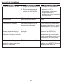
SOLUCIÓN DE PROBLEMAS
PROBLEMA CAUSA POSIBLE ACCIÓN CORRECTIVA
No hay alimentación, los leños
no arden. 1. El cable de alimentación no se
enchufó al tomacorriente.
2. El interruptor principal de
alimentación no está en la
posición de ENCENDIDO.
1. Verifi que que la unidad esté
enchufada en un tomacorriente
estándar de 120 V.
2. Presione el botón de
alimentación varias veces y
asegúrese de que la
alimentación esté en la posición
de ENCENDIDO.
Los leños arden pero no hay
efecto de fl ama. El botón de fl ama no está en la
posición de ENCENDIDO. Presione el botón de fl ama varias
veces.
El calentador no emite aire
caliente. La temperatura actual de la
habitación es más alta que la
temperatura confi gurada.
Ajuste el ajuste de temperatura
para asegurarse de que la tem-
peratura confi gurada en el termo-
stato sea mayor que la tempera-
tura actual de la habitación.
El calentador no funciona, sin
embargo hay alimentación y el
calentador está encendido y
confi gurado (consulte la solución
antes mencionada)
El producto está en modo
protegido. Coloque todos los interruptores en
la posición de APAGADO y
desconecte la unidad del
tomacorriente de pared durante
5 minutos. Luego de 5 minutos,
vuelva a enchufar la unidad en el
tomacorriente de pared y úsela
normalmente.
El efecto de fl ama funciona pero
el calentador no y el lecho de
brasas titila cuando se presiona
el botón de calentador.
El botón de calentador está
bloqueado. El botón de calentador está
bloqueado. Mantenga presionado
el botón de ALIMENTACIÓN para
desbloquear la función de
calentador.

31
GARANTÍA LIMITADA DE 1 AÑO
El fabricante garantiza que su nueva estufa eléctrica no presentará defectos de fabricación ni materiales
durante un período de un año a partir de la fecha de compra, siempre y cuando se cumplan las siguien-
tes condiciones y limitaciones.
1. Esta estufa eléctrica se debe instalar y operar en todo momento de acuerdo con las instrucciones
de instalación y operación proporcionadas con el producto. Cualquier reparación no autorizada,
alteración, abuso deliberado, accidente o uso inadecuado del producto anulará esta garantía.
2. Esta garantía no es transferible y sólo está disponible para el propietario original, siempre y cuando
la compra se haya realizado a través de un proveedor autorizado del producto.
3. Esta garantía se limita a la reparación o reemplazo de piezas que se consideren defectuosas en
material o mano de obra, siempre y cuando dicha pieza haya estado sometida a condiciones
normales de uso y servicio, después de que una inspección por parte del fabricante confi rme
dicho defecto.
4. El fabricante podrá, bajo su criterio, eximirse de toda obligación respecto de esta garantía
reembolsando el precio al por mayor de la pieza defectuosa.
5. Esta garantía no cubre·ningún costo de instalación, mano de obra, fabricación, transporte o de
otro tipo que surja de la pieza defectuosa, su reparación, reemplazo u otra situación, y el fabricante
no asume ninguna responsabilidad por las mismas.
6. El dueño/usuario asume todos los riegos, si los hay, incluidos los riesgos de daños o pérdidas
directos, indirectos o resultantes que surjan del uso del producto, o de la incapacidad para usarlo,
salvo que la ley estipule lo contrario.
7. Mediante el presente, se excluye expresamente cualquier otra garantía, expresa o implícita, respecto
del producto, sus componentes y accesorios, o cualquier otra obligación o responsabilidad de parte
del fabricante.
8. El fabricante no asume ni autoriza a ningún tercero a asumir en su nombre ninguna otra
responsabilidad respecto de la venta de este producto.
9. Las garantías descritas en este documento no se aplican a accesorios que no sean del fabricante
y que se usen junto con la instalación de este producto.
Esta garantía es nula si:
a. La chimenea está sometida a períodos prolongados de humedad o condensación.
b. Se produce cualquier alteración no autorizada, abuso deliberado, accidente o uso inadecuado
del producto.
c. Usted no tiene el recibo original de compra.
SI SE NECESITA SERVICIO DE GARANTÍA
Póngase en contacto con el fabricante llamando al departamento de Servicio al Cliente
al 1-866-661-1218, de lunes a viernes de 9 a.m. a 5 p.m., hora estándar del Este.
Asegúrese de tener su garantía, su recibo de venta, la identifi cación del lugar de
compra y el modelo o número de serie de su producto.

32
LISTA DE PIEZAS DE REPUESTO Y PLANO DE PIEZAS
Para obtener piezas de repuesto, llame al Servicio al Cliente al 1-866-661-1218, de lunes a viernes de 9
a.m. a 5 p.m., tiempo del Este.
Pieza Descripción Pieza No.
23EF023GRA Cant.
A Ensamblaje del calentador/soplador Y07-C26-P01 1
B Placa de circuitos principal Y11-C53-P15 1
C Motor de accionamiento del generador de fl amas Y07-P10Q 1
D Generador de fl amas/disco giratorio Y10-S52-P011 1
E Pantalla LCD Y10-C43-P70 1
F Pantalla de proyección frontal Y10-S52-P09 1
G Placa de circuitos de la fl ama Y11-C53-P40 1
H Lecho de brazas con leño Y10-S52-P02 1
I Placa de circuitos del panel de control Y10-S52-P32 1
J Panel de control, 4 botones Y10-C43-P25 1
K Control remoto, 4 botones P71 1
REMOTE/REMOTO/
TÉLÉCOMMANDE
A
K
BC
D
E
F
G
H
I
J
Impreso en China

ATTENTION
IF YOU HAVE ANY PROBLEMS OR QUESTIONS, EMAIL
OR CALL CUSTOMER SERVICE BEFORE YOU RETURN
THIS PRODUCT TO THE STORE WHERE IT WAS PURCHASED.
For Customer Service: email: par[email protected]
in English Call: 866-661-1218
in Spanish Call: 866-661-1218
in French Call: 866-374-9203
ATENCIÓN
SI TIENE ALGÚN PROBLEMA O PREGUNTAS,
ENVÍE UN MENSAJE DE CORREO ELECTRÓNICO O LLAME AL SERVICIO
DE ATENCIÓN AL CLIENTE ANTES DE DEVOLVER
ESTE PRODUCTO A LA TIENDA EN LA QUE LO COMPRÓ.
Servicio de atención al cliente: Correo electrónico: par[email protected]
Línea para llamadas en inglés: 866-661-1218
Línea para llamadas en español: 866-661-1218
Línea para llamadas en francés: 866-374-9203
STOP STOP
PARE PARE
ATTENTION
SI VOUS AVEZ DES PROBLÈMES OU QUESTIONS,
ENVOYEZ UN COURRIEL AU SERVICE À LA CLIENTÈLE OU APPELEZ LE
SERVICE À LA CLIENTÈLE AVANT DE RETOURNER
CE PRODUIT OÙ VOUS L’AVEZ ACHETÉ.
Pour le service à la clientèle : courriel : par[email protected]
pour le service en anglais, composez le 866-661-1218
pour le service en espagnol, composez le 866-661-1218
pour le service en français, composez le 866-374-9203
ARRÊT ARRÊT
INSTRUCTION MANUAL ENCLOSED
MANUEL D’INSTRUCTION À L’INTÉRIEUR
MANUAL DE INSTRUCCIONES ADJUNTO
INSTRUCTION MANUAL ENCLOSED
MANUEL D’INSTRUCTION À L’INTÉRIEUR
MANUAL DE INSTRUCCIONES ADJUNTO
-
 1
1
-
 2
2
-
 3
3
-
 4
4
-
 5
5
-
 6
6
-
 7
7
-
 8
8
-
 9
9
-
 10
10
-
 11
11
-
 12
12
-
 13
13
-
 14
14
-
 15
15
-
 16
16
-
 17
17
-
 18
18
-
 19
19
-
 20
20
-
 21
21
-
 22
22
-
 23
23
-
 24
24
-
 25
25
-
 26
26
-
 27
27
-
 28
28
-
 29
29
-
 30
30
-
 31
31
-
 32
32
-
 33
33
-
 34
34


Hampton Bay 23MM6072-C242 Instrucciones de operación
- Categoría
- Chimeneas
- Tipo
- Instrucciones de operación
En otros idiomas
Documentos relacionados

Otros documentos
-
Twin-Star International 18DF2433 Manual de usuario
-
-
-
-
-
Classic Flame 71388 Guía de instalación
-
-
allen+roth 4317FM-33-201 Manual de usuario