Airwell Aqu@Scop Advance R410A Guía de instalación
- Tipo
- Guía de instalación

English
Installation manual
Indoor unit floor ceiling type
AIR CONDITIONER
FLOOR CEILING
ENGLISH

GENERAL RECOMMENDATIONS
- Congratulations for having selected an our air conditioner.
SAFETY DIRECTIONS
- Follow the safety rules in force when you are working on your appliance.
- Installation and maintenance of the equipment must only be performed by qualified specialists in
accordance with the rules of good workmanship and prevailing standards and instructions.
- Make sure that the power supply and its frequency are adapted to the required electric current of
operation, taking into account specific conditions of the location and the current required for any
other appliance connected with the same circuit.
WARNING
- Cutoff power supply before starting to work on the appliance. The manufacturer declines any
responsibility and the warranty becomes void if these instructions are not respected.
- If you meet a problem, please call the Technical Department of your area.
- If possible, assemble the mandatory or optional accessories before placing the appliance on its
final Iocation.(see instruc- tions provided with each accessory)
- In order to become fully familiar with the appliance, we suggest to read also our Technical
Instructions.
- The information contained in these Instructions are subject to modification without advance notice.
IT IS MANDATORY TO CUT OFF POWER SUPPLY
BEFORE STARTING TO WORK IN THE ELECTRIC
CASING BOXES.
2
- For appliances with supplementary heaters, the minimum clearance from the appliance to
combustible is 50cm other wise, it will cause fire.
Indoor unit floor ceiling type

Indoor unit floor ceiling type
Do not attempt to install this air conditioner by yourself.
This unit contains no user-serviceable parts. Always consult authorized service personnel for repairs.
When moving, consult authorized service personnel for disconnection and installation of the unit.
Do not become excessively chilled by staying for lengthy periods in the direct cooling airflow.
Do not insert fingers or objects into the outlet port or intake grilles.
Do not start and stop air conditioner operation by disconnecting the power supply cord and so on.
Take care not to damage the power supply cord.
In the event of a malfunction (burning smell, etc.),immediately stop operation, disconnect the power supply plug, and consult authorized
service personnel.
If the power supply cord of this appliance is damaged, it should only be replaced by the authorized service personal, since special purpose
tools and specified cord are required.
Provide occasional ventilation during use.
Do not direct air flow at fireplaces or heating apparatus.
Do not climb on, or place objects on, the air conditioner.
Do not hang objects form the indoor unit.
Do not set flower vases or water containers on top of air conditioners.
Do not expose the air conditioner directly to water.
Do not pull power supply cord.
Turn off power source when not using the unit for extended periods.
Check the condition of the installation stand for damage.
Do not place animals or plants in the direct path of the air flow.
Do not drink the water drained from the air conditioner.
Do not use in applications involving the storage of foods, plants or animals, precision equipment,or art works.
Connection valves become hot during Heating; handle with care.
Do not apply any heavy pressure to radiator fins.
Operate only with air filters installed.
Do not block or cover the intake grille and outlet port.
Ensure that any electronic equipment is at least one metre away from either the indoor or outdoor units.
Avoid installing the air conditioner near a fireplace or other heating apparatus.
When installing the indoor and outdoor unit, take precautions to prevent access to infants.
Do not use inflammable gases near the air conditioner.
Danger This sign warns of death or serious injury.
Caution This sign warns of damage to property.
PRECAUTIONS
Set a suitable room temperature; excessively low room temperature is not good for your health and wastes electricity. Avoid frequent
setting of the temperature.
During cooling, avoid direct sun. Keep curtains and blinds closed. Close doors and windows to keep the cool air in the room.
Avoid generating heat or using of heating appliances while the air conditioner in cooling mode.
Make sure that the air flap is positioned properly: horizontal flow in cooling and downward vertical flow for heating.
Keep the room temperature uniform by adjusting the left/right vertical air blades.
Position the air flap and the left/right air blades in such a manner as to prevent your body from being exposed directly to air drafts.
During prolonged operation, ventilate the room occasionally by opening a window from time to time.
In a power failure, the microprocessor memory is retained. When restarted,operation will be resumed in the last mode of
operation. However, if the timer was used, the unit will be turned off by the timer only if the remote control is aimed at the
unit. Otherwise the power failure will cause the timer data to be erased from the microprocessor memory.
After turning on, allow more than 3 minutes for cooling, heating or dry operation to start.
When DRY mode is used, make sure that the room temperature is between 20 and 27 . When used out of this range,
the unit may protect itself and become inoperative.
When COOL or DRY modes are used, make sure that the room's relative humidity is below 78% lf the unit is used for a
prolonged periods of time in high humidity, moisture may form on the air outlet and drip down.
Remote control signals may not be received if the indoor unit controls cover is exposed to direct sunlight or strong light. ln
such a case, block the sunlight or dim the lighting.
The remote control is operative in a range of 8 meters. lf you are out of range, the remote control may have difficulties in
transmitting signals.
OPERATION TIPS
3
The appliance is not intended for use by young children of infirm persons without supervision.
Please pre-heat the air conditioner for at least 12 hours before operation. lf use it for a long time, please keep the power on.
ENGLISH

Indoor unit floor ceiling type
SUMMARY
DESCRIPTION
Installation/service tools.........................................................................................................................5
Operating temperature range................................................................................................................6
Dimensions of Indoor Unit .....................................................................................................................6
Dimensions of Outdoor Units.................................................................................................................6
INSTALLATION
Location of the Indoor Unit .................................................................................................................7-8
Location of the Outdoor Unit..................................................................................................................9
Refrigerant Line...................................................................................................................................10
Installation.......................................................................................................................................
1
Electrical Connections....................................................................................................................
Final Tasks.................................................................................................................
4

Indoor unit floor ceiling type
CAUTION
Incidentally, the "refrigerant cylinder" comes with the refrigerant designation (R410A) and protector coating in the
U.S's ARI specified rose color (ARI color code: PMS 507).
Also, the "charge port and packing for refrigerant cylinder" requires 1/2 UNF 20 threads per inch corresponding
to the charge hose's port size.
New Refrigerant Air Conditioner Installation
THIS AIR CONDTIONER ADOPTS THE NEW HFC REFRIGERANT (R410A) WHICH DOES NOT DESTROY OZONE
LAYER. R410A refrigerant is apt to be affected by impurities such as water, oxidizing membrane, and oils because the working
pressure of R410A refrigerant is approx. 1.6 times of refrigerant R22. Accompanied with the adoption of the new refrigerant, the
refrigeration machine oil has also been changed. Therefore, during installation work, be sure that water, dust, former refrigerant,
or refrigeration machine oil does not enter into the new type refrigerant R410A air conditioner circuit.
To prevent mixing of refrigerant or refrigerating machine oil, the sizes of connecting sections of charging port on main unit and
installation tools are different from those used for the conventional refrigerant units. Accordingly, special tools are required for
the new refrigerant (R410A) units. For connecting pipes, use new and clean piping materials with high pressure fittings made for
R410A only, so that water and/or dust does not enter. Moreover, do not use the existing piping because there are some
problems with pressure fittings and possible impurities in existing piping.
Changes in the product and components
In air conditioners using R410A, in order to prevent any other refrigerant from being accidentally charged, the service port
diameter size of the outdoor unit control valve (3 way valve) has been changed. (1/2 UNF 20 threads per inch)
In order to increase the pressure resisting strength of the refrigerant piping, flare processing diameter and
opposing flare nuts sizes have been changed. (for copper pipes with nominal dimensions 1/2 and 5/8)
As the working pressure is high, it is impossible to measure the
working pressure using conventional gauges. In order to prevent
any other refrigerant from being charged, the port diameters have
been changed.
In order to increase pressure resisting
strength, hose materials
and port
sizes have been changed (to 1/2 UNF 20 threads per
inch).
When purchasing a charge hose, be sure to confirm the port size.
As working pressure is high and gasification speed is fast, it is
difficult to read the indicated value by means of charging cylinder,
as air bubbles occur.
The size of opposing flare nuts have been increased. Incidentally,
a common wrench is used for nominal diameters 1/4 and 3/8.
By increasing the clamp bar's receiving hole size, strength of
spring in the tool has been improved.
Used when flare is made by using conventional flare tool.
Connected to conventional vacuum pump. It is necessary to use
an adapter to prevent vacuum pump oil from flowing back into
the charge hose. The charge hose connecting part has two ports
-- one for conventional refrigerant (7/16 UNF 20 threads per inch)
and one for R410A. If the vacuum pump oil (mineral) mixes with
R410A a sludge may occur and damage the equipment.
Exclusive for HFC refrigerant.
New tools for R410A Applicable to R22 model Changes
Gauge manifold
Charge hose
Electronic balance for
refrigerant charging
Torque wrench
(nominal dia. 1/2, 5/8)
Flare tool (clutch type)
Gauge for projection
adjustment
Vacuum pump adapter
Gas leakage detector
New tools for R410A
INSTALLATION/SERVICE TOOLS
5
ENGLISH

Indoor unit floor ceiling type
DIMENSIONS OF OUTDOOR UNITS
DIMENSIONS OF INDOOR UNIT
6
Unit: mm
Unit: mm
B
E
C
D
A
Model (KBtu/h) A B C D E
18/24 1068 675 235 983 220
30 1285 675 235 1200 220
36/48/60 1650 675 235 1565 220
12/18/24 1068 675 235 983 220
30/36/48 1285 675 235 1200 220
60 1650 675 235 1565 220
36 1285 675 235 1200 220
48/60 1650 675 235 1565 220
DC INVERTER
ON-OFF
(50Hz)
ON-OFF
(60Hz)
A
H
B
C
D
E
F
CAPACITY
(KBtu/h)
A B C D E F H
12 780 548 266 300 241 250 540
18 760 530 290 315 270 285 590
24 845 560 335 360 312 320 700
30/36 990 624 366 396 340 345 965
48/60 938 634 404 448 368 392 1369
CAPACITY
(KBtu/h)
A B C D E F H
12 760 530 290 315 270 285 590
18 845 560 335 360 312 320 700
24/30 900 590 333 355 302 315 860
36 990 624 366 396 340 345 965
48/60 938 634 404 448 368 392 1369
A
B
C
Capacity (KBtu/h) A B C
36 759 600 600
48 759 710 710
60 843 710 710
DC INVERTER
ON-OFF(50Hz
ON-OFF(60Hz

Indoor unit floor ceiling type
7
it
condersation water is easily drained
out.
Such a place that can handle the weight of indoor unit.
Such a place which has easy access for maintenance.
SELECTION OF INSTALLATION LOCATION.
THERE ARE 2 STYLES OF INSTALLATION.
CEILING TYPE
FLOOR TYPE
Each type is similar to the other as follows;
Determine the mounting position on ceiling or wall
by using paper pattern to indicate indoor frarne.
Mark the pattern and pull out the paper pattern.
Remove the return grill,the side panel and the hanger
bracket from the indoor unit as per procedure bellow.
Press the fixing knob of the relurn grilles, the grilles
will be opened wider and then pull it out from
the indoor.
CAUTION FOR INSTALLATION WHERE
AIR CONDITIONER TROUBLE IS LIKELY
TO OCCUR.
Where there is too much of oil.
Where it is acid base area.
Where there is irregular electrical supply.
Indoor Unit Instrallation
INSTALLATION INSTRUCTIONS
INSTALLATION
PAPER PLANK
100cm
or more
30cm
or more
60cm
or more
60cm
or more
150cm
or more
ENGLISH

Indoor unit floor ceiling type
8
Indoor Unit Installation
a
Side board
Hanging arm
Hanging
screw bolt
Ceiling Installation
20mm
Downward slope : (1-2)/100
Wall Mounting Installtion

Indoor unit floor ceiling type
INSTALLATION OF THE OUTDOOR UNIT
- Minimum clearance to respect (in mm).
minimum
9
ENGLISH

Indoor unit floor ceiling type
REFRIGERANT CONNECTIONS
10
CAPACITY
(KBtu/h)
TUBE OD: LIQUID - GAS
(Inch)
A- L.MAX
(m)
B - H.MAX
(m)
LENGTH OF
PRECHARGE
(m)
ADDITIONAL
CHARGE
(g/m)
12 1/4"-1/2" 20 10 5 15
18 1/4"-1/2" 25 15 5 15
24 3/8"-5/8" 25 15 5 30
30 3/8"-3/4" 25 15 5 30
36 3/8"-3/4" 30 20 5 30
48/60 3/8"-3/4" 50 25 5 30
CAPACITY
(KBtu/h)
TUBE OD: LIQUID - GAS
(Inch)
A- L.MAX
(m)
B - H.MAX
(m)
LENGTH OF
PRECHARGE
(m)
ADDITIONAL
CHARGE
(g/m)
12 1/4"-3/8" 20 10 5 15
18 1/4"-1/2" 30 20 5 15
24/30 3/8"-5/8" 50 25 5 30
36/48/60 3/8"
-5/8" 65 25 5 30
MAXIMUM PIPE LENGTH & HEIGHT (TYPE ON-OFF)
MAXIMUM PIPE LENGTH & HEIGHT (TYPE INVERTER)

Indoor unit floor ceiling type
INSTALLATION OF TUBING ON WALL SUPPORT
- After choosing your coolant tubing input location (right, left or rear), you can set up your tubing. To
do this, use the installation template in order to form the tubes correctly and thus facilitate
connection.
11
- Fit the nuts of the (for med) tubing into the recess provided on the template.
- Secure the tubing with the clamps provided.
- Remove the tubing template; you can now install your unit on its support.
INSTALLATION OF TUBING ON WALL SUPPORT
- Locate the LIQUID tube above the GAS tube.
NOTE
output to the rear
- The slanted hole prevents
condensates or rain from
entering the unit.
- Fit a Dia. 70 mm sleeve into
the hole.
ENGLISH

Indoor unit floor ceiling type
2 Connect the vacuum pump with the flare coupling of the outdoor unit equipped with a process
valve.
3 Start the vacuum pump and check that the needle of the indicator goes down to - 0,2 mm Hg.
The pump should run during at least 15 minutes.
4 Before disconnecting the vacuum pump, check that the vacuum indicator remains in the same
position during five minutes.
5 Disconnect the vacuum pump.
6 Remove the cap of the "GAS" and "LIQUID" valves and open them with a hexagonal wrench to
free the R410A contained in the outdoor unit.
7 Check that the linking pipes are sealed. Use an electronic leak detector or a soapy sponge.
VACUUM OF COOLING PIPES AND INDOOR UNIT
- Only the outdoor unit is charged with R410A cooling fluid. The indoor unit contains a small quantity
of a neutral gas. This the reason it is imperative to vacuum the linking pipes and the indoor unit.
ASSEMBLY
- The outdoor unit is equipped with a valve allowing to vacuum the installation (large valve)
1 Connect the connecting pipes to the outdoor unit by FLARE NUTS and to the indoor unit by
BRAZING
- To obtain the right tightening, cover the sur face with cooling oil.
- The use of a counter wrench is required to tighten the valves.
- The values of the tightening torque are shown in the table below.
1
Pipe Diameter Tightening Torque

Capacity 36K 48K
60K
Power supply
Fuse Rating(ODU/IDU) 30A / 16A 45A/16A 50A/16A
1- Power Cable (ODU)
3 x 4.0mm
2
3 x 6.0mm
2
3 x10.0mm
2
2- Power Cable (IDU)
3 x 1.0mm
2
3 x 1.0mm
2
3 x 1.0mm
2
3- Interconnecting Cable
Indoor & Outdoor
ON-OFF TYPE(60Hz)
36/48/60 KBtu/h
220V 1~ 60Hz
220V 1~ 60Hz
Indoor unit floor ceiling type
100
40
8
8
BA
ELECTRICAL CONNECTION BETWEEN INDOOR AND OUTDOOR UNIT
ELECTRICAL REQUIREMENTS
Electrical wiring and connections should
be made by qualified electricians and in
accordance with local electrical codes
and regulation. The air conditioner units
must be grounded.
The air conditioner unit must be
connected to an adequate power outlet
from a separate branch circuit protected
by a time delay circuit breaker, as
specified on unit's nameplate.
Voltage should not vary beyond 10% of
the rated voltage.
An all-pole disconnection switch having a
contact separation of at least 3mm in all
poles should be connected in fixed wiring.
1. To connect the indoor unit to the
outdoor unit use the following electrical
cables.
NOTES: The wire color code can be
selected by the installer.
2. Prepare the needed cables for
electrical connection.
3. Connect the cable ends to the
terminals of the indoor and outdoor
units.
4. Secure the multiple wire power cable
with the cable clamps.
The temperature of refrigerant
circuit will be high, please keep
the interconnection cable away
from the copper tube.
1
ENGLISH
2 x 0.5mm
2
2 x 0.5mm
2
2 x 0.5mm
2
C1 N1
C1 N1

ON-OFF TYPE(50Hz)
Capacity 12/18K 24K 30K/36K
Power supply
Fuse Rating 16A 25A 30A
1- Power Cable (IDU)
3 x 1.5mm
2
3 x 2.5mm
2
3 x 4.0mm
2
2- Interconnecting Cable
3 x 1.5mm
2
3 x 2.5mm
2
3 x 4.0mm
2
3- Interconnecting Cable
2 x 1.0mm
2
3 x 1.0mm
2
3 x 1.0mm
2
4- Interconnecting Cable
2 x 0.5mm
2
2 x 0.5mm
2
2 x 0.5mm
2
From Indoor
Capacity 36K (3Ph) 48K 60K
Power supply From Outdoor
Fuse Rating (ODU/IDU) 20A /- 25A / 16A 25A / 16A
1- Power Cable (ODU)
5 x 2.5mm
2
5 x 2.5mm
2
5 x 2.5mm
2
2- Power Cable (IDU) -
3 x 1.0mm
2
3 x 1.0mm
2
3- Interconnecting Cable
3 x 1.0mm
2
3 x 0.5mm
2
3 x 0.5mm
2
4- Interconnecting Cable
3 x 1.0mm
2
- -
Indoor & Outdoor
Indoor unit floor ceiling type
1
24/30/36KBtu/h
230V 1~ 50Hz 230V 1~ 50Hz

INVERTER TYPE
Capacity 18k 24k 30k 36k
Power supply
Fuse Rating (ODU/IDU) 16A / 10A 20A / 10A 30A / 10A 30A / 10A
1- Power Cable (ODU)
3 x 2.5mm
2
3 x 2.5mm
2
5 x 2.5mm
2
5 x 4.0mm
2
2- Power Cable (IDU)
3 x 1.0mm
2
3 x 1.0mm
2
3 x 1.0mm
2
3 x 1.0mm
2
3- Interconnecting Cable
3 x 0.5mm
2
3 x 0.5mm
2
3 x 0.5mm
2
3 x 0.5mm
2
Indoor & Outdoor
Capacity 36k(3Ph) 48K 60K
Power supply
Fuse Rating (ODU/IDU) 20A / 10A 25A / 10A 25A / 10A
1- Power Cable (ODU)
5 x 2.5mm
2
5 x 2.5mm
2
5 x 2.5mm
2
2- Power Cable (IDU)
3 x 1.0mm
2
3 x 1.0mm
2
3 x 1.0mm
2
3- Interconnecting Cable
3 x 0.5mm
2
2 x 0.5mm
2
2 x 0.5mm
2
Indoor & Outdoor
Indoor unit floor ceiling type
ENGLISH
1. Check all valve caps and ensure that they had been tightened properly. Close the valve
cover.
2. Fill gaps on the wall between hole sides and tubing with sealer.
3. Attach wiring and tubing to the wall with clamps where necessary.
4. Operate the unit for no less than 5 minutes at heating or cooling mode.
5. Explain filter removal, cleaning and installation.
6. Operate the air conditioner together with the customer and explain all functions.
7. Give the operating and installation manuals to the customer.
FINAL TASKS


DEUTSCH
Deutsch
Montageanleitung
TRUHEN-SPLITKLIMAGERÄTE
Truhen-splitklimageräte


DEUTSCH

11
13
15
Letzte vorkehrungen

DEUTSCH

Unit: mm
Unit: mm
B
E
C
D
A
KAPAZITÄT (KBtu/h) A B C D E
18/24 1068 675 235 983 220
30 1285 675 235 1200 220
36/48/60 1650 675 235 1565 220
12/18/24 1068 675 235 983 220
30/36/48 1285 675 235 1200 220
60 1650 675 235 1565 220
36 1285 675 235 1200 220
48/60 1650 675 235 1565 220
DC INVERTER
ON-OFF
(50Hz)
ON-OFF
(60Hz)
A
H
B
C
D
E
F
KAPAZITÄT
(KBtu/h)
A B C D E F H
12 780 548 266 300 241 250 540
18 760 530 290 315 270 285 590
24 845 560 335 360 312 320 700
30/36 990 624 366 396 340 345 965
48/60 938 634 404 448 368 392 1369
KAPAZITÄT
(KBtu/h)
A B C D E F H
12 760 530 290 315 270 285 590
18 845 560 335 360 312 320 700
24/30 900 590 333 355 302 315 860
36 990 624 366 396 340 345 965
48/60 938 634 404 448 368 392 1369
A
B
C
KAPAZITÄT (KBtu/h) A B C
36 759 600 600
48 759 710 710
60 843 710 710
DC INVERTER
ON-OFF(50Hz
ON-OFF(60Hz

Installation der Inneneinheit
AUSWAHL DES INSTALLATIONSORTES.
ACHTUNG: VERMEIDEN SIE
INSTALLATIONEN, WO DIE KLIMAANLAGE
PROBLEME BEKOMMT.
ES GIBT 2 INSTALLATIONSARTEN.
DECKENMONTAGE
BODENNAHE MONTAGE
60 cm
oder mehr
100 cm
oder
mehr
30 cm
oder mehr
60 cm
oder mehr
150 cm
oder mehr
DEUTSCH

Side board
Hanging arm
Hanging
screw bolt
Ceiling Installation
20mm
Downward slope : (1-2)/100
Wall Mounting Installtion
Installation der Inneneinheit

DEUTSCH

KAPAZITÄT
(KBtu/h)
FLÜSSIGKEITSLEITUNG
-GASLEITUNG
(Inch)
A- L.MAX
(m)
B - H.MAX
(m)
LÄNGE DER
PRECHARGE
(m)
ZUSÄTZLICH
(g/m)
12 1/4"-1/2" 20 10 5 15
18 1/4"-1/2" 25 15 5 15
24 3/8"-5/8" 25 15 5 30
30 3/8"-3/4" 25 15 5 30
36 3/8"-3/4" 30 20 5 30
48/60 3/8"-3/4" 50 25 5 30
KAPAZITÄT
(KBtu/h)
FLÜSSIGKEITSLEITUNG
-GASLEITUNG
(Inch)
A- L.MAX
(m)
B - H.MAX
(m)
LÄNGE DER
PRECHARGE
(m)
ZUSÄTZLICH
(g/m)
12 1/4"-3/8" 20 10 5 15
18 1/4"-1/2" 30 20 5 15
24/30 3/8"-5/8" 50 25 5 30
36/48/60 3/8"-5/8" 65 25 5 30
Maximale Rohrlänge und Höhe (TYP ON-OFF)
Maximale Rohrlänge und Höhe (TYP INVERTER

DEUTSCH

Pipe Diameter Tightening Torque

Kapazität
Stromversorgung
Fuse Rating (ODU/IDU)
1- Stromversorgungskabel (ODU)
2- Stromversorgungskabel (IDU)
3- Verbindungskabel
36K 48K
60K
30A / 16A 45A/16A 50A/16A
3 x 4.0mm
2
3 x 6.0mm
2
3 x10.0mm
2
3 x 1.0mm
2
3 x 1.0mm
2
3 x 1.0mm
2
INNENGERÄT und AUSSENGERÄT
ON-OFF TYPE(60Hz)
36/48/60 KBtu/h
220V 1~ 60Hz
220V 1~ 60Hz
2 x 0.5mm
2
2 x 0.5mm
2
2 x 0.5mm
2
C1 N1
C1 N1
DEUTSCH
Schaltvorkehrungen
INNENGERÄT
AUSSENGERÄT

ON-OFF TYPE(50Hz)
INNENGERÄT
AUSSENGERÄT
24/30/36 KBtu/h
230V 1~ 50Hz 230V 1~ 50Hz
INNENGERÄT
AUSSENGERÄT
Kapazität 12/18K 24K 30K/36K
Stromversorgung
Fuse Rating 16A 25A 30A
1- Stromversorgungskabel (IDU)
3 x 1.5mm
2
3 x 2.5mm
2
3 x 4.0mm
2
2- Verbindungskabel
3 x 1.5mm
2
3 x 2.5mm
2
3 x 4.0mm
2
3- Verbindungskabel
2 x 1.0mm
2
3 x 1.0mm
2
3 x 1.0mm
2
4- Verbindungskabel
2 x 0.5mm
2
2 x 0.5mm
2
2 x 0.5mm
2
INNENGERÄT
Kapazität 36K (3Ph) 48K 60K
Stromversorgung AUSSENGERÄT
Fuse Rating (ODU/IDU) 20A /- 25A / 16A 25A / 16A
1- Stromversorgungskabel (ODU)
5 x 2.5mm
2
5 x 2.5mm
2
5 x 2.5mm
2
2- Stromversorgungskabel (IDU) -
3 x 1.0mm
2
3 x 1.0mm
2
3- Verbindungskabel
3 x 1.0mm
2
3 x 0.5mm
2
3 x 0.5mm
2
4-Verbindungskabel
3 x 1.0mm
2
- -
INNENGERÄT und AUSSENGERÄT
INNENGERÄT
AUSSENGERÄT
INNENGERÄT
AUSSENGERÄT

INNENGERÄT
AUSSENGERÄT
INNENGERÄT
AUSSENGERÄT
Kapazität 18k 24k 30k 36k
Stromversorgung
Fuse Rating (ODU/IDU) 16A / 10A 20A / 10A 30A / 10A 30A / 10A
1- Stromversorgungskabel(ODU)
3 x 2.5mm
2
3 x 2.5mm
2
5 x 2.5mm
2
5 x 4.0mm
2
2- Stromversorgungskabel(IDU)
3 x 1.0mm
2
3 x 1.0mm
2
3 x 1.0mm
2
3 x 1.0mm
2
3- Verbindungskabel
3 x 0.5mm
2
3 x 0.5mm
2
3 x 0.5mm
2
3 x 0.5mm
2
IINNENGERÄT und AUSSENGERÄT
Kapazität 36k(3Ph) 48K
Stromversorgung
Fuse Rating (ODU/IDU) 20A / 10A 25A / 10A
1- Stromversorgungskabel(ODU)
5 x 2.5mm
2
5 x 2.5mm
2
2- Stromversorgungskabel(IDU)
3 x 1.0mm
2
3 x 1.0mm
2
3- Verbindungskabel
3 x 0.5mm
2
2 x 0.5mm
2
IINNENGERÄT und AUSSENGERÄT
INVERTER TYPE
DEUTSCH
1. Prüfen Sie, ob die Ventildeckel gut verschlossen sind. Schließen Sie die Ventildeckel.
2. Füllen Sie die Zwischenräume an der Wand zwischen den Öffnungsseiten und den
Leitungsrohren mit Dichtungsmaterial.
3. Befestigen Sie die Kabel und Rohre nötigenfalls mit Klemmen an der Wand.
4. Lassen Sie das Gerät während mindestens5Minuten im Heiz- oder Kühlbetrieb laufen.
5. Erklären Sie dem Kunden die Filterentfernung, -reinigun g und -montage.
6. Setzen Sie das Klimagerät zusammen mit dem Kunden in Betrieb und erklären Sie ihm alle
Funktionen.
7. Überreichen Sie dem Kunden die Betriebs- und Montageanleitungen.
LETZTE VORKEHRUNGEN


FRANCAIS
Manuel d'installation
CLIMATISEUR
Split system Allège / plafonnier

2

3
FRANCAIS

4
6
6
7-8
10
11
13
15
Tâches finales

ATTENTION
5
FRANCAIS

Unit: mm
A
H
B
C
D
E
F
CAPACITE
(KBtu/h)
A B C D E F H
12 780 548 266 300 241 250 540
18 760 530 290 315 270 285 590
24 845 560 335 360 312 320 700
30/36 990 624 366 396 340 345 965
48/60 938 634 404 448 368 392 1369
CAPACITE
(KBtu/h)
A B C D E F H
12 760 530 290 315 270 285 590
18 845 560 335 360 312 320 700
24/30 900 590 333 355 302 315 860
36 990 624 366 396 340 345 965
48/60 938 634 404 448 368 392 1369
A
B
C
KAPAZITÄT (KBtu/h) A B C
36 759 600 600
48 759 710 710
60 843 710 710
DC INVERTER
ON-OFF(50Hz
ON-OFF(60Hz
Unit: mm
B
E
C
D
A
CAPACITE (KBtu/h) A B C D E
18/24 1068 675 235 983 220
30 1285 675 235 1200 220
36/48/60 1650 675 235 1565 220
12/18/24 1068 675 235 983 220
30/36/48 1285 675 235 1200 220
60 1650 675 235 1565 220
36 1285 675 235 1200 220
48/60 1650 675 235 1565 220
DC INVERTER
ON-OFF
(50Hz)
ON-OFF
(60Hz)
6

Installation de l’unité intérieure
INSTRUCTIONS RELATIVES A L’'INSTALLATION
CHOIX DU LIEU D'INSTALLATION
Choisir un endroit où l'eau de condensation peut facilement
être évacuée.
Choisir un endroit capable de supporter le poids de l'unité
intérieure.
Choisir un endroit facilement accessible pour des besoins
de maintenance.Choisir un endroit qui facilite le
raccordement avec l’unité extérieure.
Choisir un emplacement à 1 m ou plus des appareils électriques
comme des téléviseurs ou autres appareils audio.
Eviter des endroits où il existe une source thermique, un
niveau d'humidité élevéou des gaz inflammables.
Ne pas utiliser l'appareil à proximité d'un bac à linge, d'une
salle de bain, d'une douche ou d'une piscine.
Veiller à ce que l'installation soit conforme aux dimensions
et au schéma
de montage.
L'espace autour de l'appareil doit être adéquat pour la
ventilation (cf. Fig.23)
IL EXISTE DEUX TYPES D’INSTALLATION :
INSTALLATION AU PLAFOND
INSTALLATION SUR LE PLANCHER
AVERTISSEMENT: EVITER D'INSTALLER
LE CLIMATISEURDANS UN ENDROIT OU IL
PEUT ETRE SOUMIS A DES
PERTURBATIONS.
- Eviter les endroits où il y a beaucoup d'huile.
- Eviter des zones de production du gaz alcalin et
acide.
- Eviter les endroits avec une tension électrique
irrégulière
Les deux types d'installation présentent les points de
convergence en ce qui concerne les étapes ci-
dessous:
Définition de la position de montage sur le plafond ou
sur le mur en utilisant un modèle sur papier pour
reproduire le cadre intérieur. Marquage du motif et
retrait du modèle sur papier;
retrait de la grille de reprise, du panneau latéral et du
support d'accrochagede l'unité intérieure conformément
à la méthode ci-dessous;
A
ppuyer sur le bouton de fixation des grilles de reprise.
L'ouverture des grilles sera plus large. Tirer ensuite
l'appareil hors du
boîtier.
Retirer la vis de fixation du panneau latéral, tirer
PLANCHE DU
PAPER
vers l'avant (selon le sens de la flèche) pour
l'enlever (voir Fig.24)
FRANCAIS

Side board
Hanging arm
Hanging
screw bolt
Ceiling Installation
20mm
Downward slope : (1-2)/100
Wall Mounting Installtion
Fixer le boulon d'accrochage (utiliser les boulons d'accrochage de taille W3/8 ou M10)
Régler la distance entre l'appareil et la dalle ou le plafond au préalable .
Fixer le support d'accrochage sur le boulon de suspension.
AVERTISSEMENT:
veiller à ce que le boulon d'accrochage en saillie sur le plafond soit fixé sur la zone marquée par les
flèches. Réajuster le support d'accrochage s'il se trouve en dehors de la zone marquée par la flèche
le boulon d'accrochage doit être fixé à l'intérieur du couvercle du boîtier. Ne jamais retirer le
couvercle.
Soulever l'appareil, le faire glisser jusqu'à la protubérance .
Fixer les deux boulons de fixation du support d'accrochage (M8) .
Serrer les boulons de fixation du support d'accrochage (M6) pour éviter tout jeu au niveau de l'unité
intérieure .
Régler la hauteur de l'appareil de telle manière que le côté arrière du tuyau d'évacuation soit légèrement
incliné pour améliorer l'évacuation.
AVERTISSEMENT:
Ajuster la hauteur en tournant le boulon à l'aide d'une clé.
Insérer la clé dans l'ouverture du support d'accrochage .
Cas de suspension
Il est possible d'installer le climatiseur en utilisant les supports d'accrochage orientés vers l'intérieur, sans
retirer les supports de l'unité intérieure .
Utiliser exclusivement les accessoires et les pièces spécifiés pour les travaux d'installation.

DCI 25-35-50-60-72-80
9
FRANCAIS

CAPACITE
(KBtu/h)
TUBE
LIQUIDE -GAZ
(Inch)
A- L.MAX
(m)
B - H.MAX
(m)
LONGUEUR DE
PRECHARGE
(m)
CHARGE
SUPPLÉMENTAIRES
(g/m)
12 1/4"-1/2" 20 10 5 15
18 1/4"-1/2" 25 15 5 15
24 3/8"-5/8" 25 15 5 30
30 3/8"-3/4" 25 15 5 30
36 3/8"-3/4" 30 20 5 30
48/60 3/8"-3/4" 50 25 5 30
CAPACITE
(KBtu/h)
TUBE
LIQUIDE -GAZ
(Inch)
A- L.MAX
(m)
B - H.MAX
(m)
LONGUEUR DE
PRECHARGE
(m)
CHARGE
SUPPLÉMENTAIRES
(g/m)
12 1/4"-3/8" 20 10 5 15
18 1/4"-1/2" 30 20 5 15
24/30 3/8"-5/8" 50 25 5 30
36/48/60 3/8"-5/8" 65 25 5 30
MAXIMALE TUBE longueur et Hauteur (TYPE ON-OFF)
MAXIMALE TUBE longueur et Hauteur (TYPE INVERTER)
10

11
FRANCAIS

12
80-85 (N·m)

Capacité
Côté d'alimentation
Calibre fusible (ODU/IDU)
1- Câble d’alimentation (ODU)
2- Câble d’alimentation(IDU)
3- Câble d’interconnexion
Unité Intérieure
Unité Extérieur
36K 48K
60K
30A / 16A 45A/16A 50A/16A
3 x 4.0mm
2
3 x 6.0mm
2
3 x10.0mm
2
3 x 1.0mm
2
3 x 1.0mm
2
3 x 1.0mm
2
Unité Intérieure et Unité Extérieur
ON-OFF TYPE(60Hz)
36/48/60 KBtu/h
220V 1~ 60Hz
220V 1~ 60Hz
2 x 0.5mm
2
2 x 0.5mm
2
2 x 0.5mm
2
C1 N1
C1 N1
Un interrupteur multipolaire de debranchement avec
une separation du contact d'au moins 3 mm pour
tous les poles devrait etre raccorde en cablage fixe.
13
FRANCAIS

24/30/36 KBtu/h
230V 1~ 50Hz 230V 1~ 50Hz
ON-OFF TYPE(50Hz)
Unité Intérieure
Unité Extérieur
Unité Intérieure
Unité Extérieur
Unité Intérieure
Unité Extérieur
Unité Intérieure
Unité Extérieur
Capacité 12/18K 24K 30K/36K
Côté d'alimentation
Calibre fusible 16A 25A 30A
1- Câble d’alimentation(IDU)
3 x 1.5mm
2
3 x 2.5mm
2
3 x 4.0mm
2
2- Câble d’interconnexion
3 x 1.5mm
2
3 x 2.5mm
2
3 x 4.0mm
2
3- Câble d’interconnexion
2 x 1.0mm
2
3 x 1.0mm
2
3 x 1.0mm
2
4- Câble d’interconnexion
2 x 0.5mm
2
2 x 0.5mm
2
2 x 0.5mm
2
Unité Intérieure
Capacité 36K (3Ph) 48K 60K
Côté d'alimentation Unité Extérieur
Calibre fusible (ODU/IDU) 20A /- 25A / 16A 25A / 16A
1- Câble d’alimentation (ODU)
5 x 2.5mm
2
5 x 2.5mm
2
5 x 2.5mm
2
2- Câble d’alimentation(IDU) -
3 x 1.0mm
2
3 x 1.0mm
2
3- Câble d’interconnexion
3 x 1.0mm
2
3 x 0.5mm
2
3 x 0.5mm
2
4-Câble d’interconnexion
3 x 1.0mm
2
- -
Unité Intérieure et Unité Extérieur
14

Unité Intérieure
Unité Extérieur
Unité Intérieure
Unité Extérieur
INVERTER TYPE
Capacité 18k 24k 30k 36k
Côté d'alimentation
Calibre fusible (ODU/IDU) 16A / 10A 20A / 10A 30A / 10A 30A / 10A
1- Câble d’alimentation(ODU)
3 x 2.5mm
2
3 x 2.5mm
2
5 x 2.5mm
2
5 x 4.0mm
2
2- Câble d’alimentation(IDU)
3 x 1.0mm
2
3 x 1.0mm
2
3 x 1.0mm
2
3 x 1.0mm
2
3- Câble d’interconnexion
3 x 0.5mm
2
3 x 0.5mm
2
3 x 0.5mm
2
3 x 0.5mm
2
Capacité 36k(3Ph) 48K 60K
Côté d'alimentation
Calibre fusible (ODU/IDU) 20A / 10A 25A / 10A 25A / 10A
1- Câble d’alimentation(ODU)
5 x 2.5mm
2
5 x 2.5mm
2
5 x 2.5mm
2
2- Câble d’alimentation(IDU)
3 x 1.0mm
2
3 x 1.0mm
2
3 x 1.0mm
2
3- Câble d’interconnexion
3 x 0.5mm
2
2 x 0.5mm
2
2 x 0.5mm
2
Unité Intérieure et Unité Extérieur
Unité Intérieure et Unité Extérieur
15
FRANCAIS
1. Vérifiez tous les bouchons de valves et assurez-vous qu'ils sont correctement serrés.
Fermez le couvercle de la valve.
2. Remplissez au joint les jeux sur le mur entre les trous latéraux et la tuyauterie.
3. Fixez le câblage et la tuyauterie au mur avec les clames, là où ce sera nécessaire.
4. Faites fonctionner l'unité au moins cinq minutes en modes Chauffage ou Refroidissement.
5. Expliquez le retrait de filtre, le nettoyage et l'installation.
6. Faites fonctionner le climatiseur devant le client et expliquez toutes les fonctions.
7. Remettez les manuels d'opération et d'installation au client.
TÂCHES FINALES


ESPAÑOL
ACONDICIONADOR DE
AIRE
MURAL / DE TECHO
Número
Manual de Instalación
Split system mural / de techo

2

3
ESPAÑOL

4
6
6
7-8
9
10
11
1
6
Tareas finales

5
ESPAÑOL

Unit: mm
Unit: mm
B
E
C
D
A
CAPACIDAD (KBtu/h) A B C D E
18/24 1068 675 235 983 220
30 1285 675 235 1200 220
36/48/60 1650 675 235 1565 220
12/18/24 1068 675 235 983 220
30/36/48 1285 675 235 1200 220
60 1650 675 235 1565 220
36 1285 675 235 1200 220
48/60 1650 675 235 1565 220
DC INVERTER
ON-OFF
(50Hz)
ON-OFF
(60Hz)
A
H
B
C
D
E
F
CAPACIDAD
(KBtu/h)
A B C D E F H
12 780 548 266 300 241 250 540
18 760 530 290 315 270 285 590
24 845 560 335 360 312 320 700
30/36 990 624 366 396 340 345 965
48/60 938 634 404 448 368 392 1369
CAPACIDAD
(KBtu/h)
A B C D E F H
12 760 530 290 315 270 285 590
18 845 560 335 360 312 320 700
24/30 900 590 333 355 302 315 860
36 990 624 366 396 340 345 965
48/60 938 634 404 448 368 392 1369
A
B
C
CAPACIDAD(KBtu/h) A B C
36 759 600 600
48 759 710 710
60 843 710 710
DC INVERTER
ON-OFF(50Hz
ON-OFF(60Hz
6

Instalación de Unidad de Interior
INSTRUCCIONES DE INSTALACIÓN
SELECCIÓN DE UBICACIÓN DE
INSTALACIÓN.
Un lugar donde la condensación de agua se pueda
disipar fácilmente.
Un lugar que pueda sostener el peso de una unidad de
interior.
Un lugar que tenga fácil acceso para dar
mantenimiento.
Un lugar que permita una fácil conexión con la unidad
de exterior.
Un lugar que esté a 1m o más de distancia de otros
aparatos eléctricos como televisores y dispositivos de
audio.
Evite lugares donde haya fuentes de calor, alta
humedad o gas inflamable.
No use la unidad en la cercanía inmediata de la
lavandería, baño, regadera o piscina.
Asegúrese que la instalación conforme con el diagrama
de dimensiones de instalación.
El espacio alrededor de la unidad debe ser adecuado
para su ventilación. (Ver Fig. 23)
HAY DOS TIPOS DE INSTALACIÓN
TIPO CIELO
TIPO PISO
Estos tipos son similares entre sí como se indica;
Determine la posición de montaje en cielo o pared usando
un patrón de papel para indicar el marco interior. Marque
el patrón y saque el patrón de papel. Quite la rejilla de
retorno, el panel lateral y el soporte colgante de la unidad
de interior conforme al siguiente procedimiento.
Presione el broche de las rejillas de retorno, las rejillas
se abrirán y luego jale para quitarla de la unidad de
interior.
Quite el tornillo de sujeción del panel lateral y jálelo
hacia el frente (dirección de la flecha) para quitarlo.
(Ver Fig. 24)
Afloje los dos pernos guía del soporte colgante (M8) de
cada lado a menos de 10mm. Quite los dos tornillos del
soporte colgante (M6) en el lado posterior. Quite el
soporte colgante jalándolo hacia atrás (Ver Fig. 26)
TENGA CUIDADO AL INSTALAR DONDE
PUEDA HABER PROBLEMAS CON EL AIRE
ACONDICIONADO
Donde hay demasiado aceite
Donde sea un área de acido básico.
Donde hay alimentación de energía irregular.
Fig. 22
Fig. 23
Fig. 24
60cm
ESPAÑOL

Side board
Hanging arm
Hanging
screw bolt
Ceiling Installation
20mm
Downward slope : (1-2)/100
Wall Mounting Installtion
Instalación de Unidad de Interior
INSTRUCCIONES DE INSTALACIÓN
Ajuste el perno de suspensión. (Use pernos de suspensión de tamaño W3/8 o M10)
Ajuste la distancia de la unidad a la losa de cielo con anterioridad
Fije el soporte colgante al perno de suspensión. ADVERTENCIA
Asegúrese que el perno de suspensión extendido desde el cielo se mantenga en el interior de la posición con
flecha. Reajuste el soporte colgante cuando esté fuera de la posición con flecha.
El perno de suspensión se mantiene en el interior de la tapa de la unidad de interior. Nunca quite la tapa.
Levante la unidad y deslícela en el diente.
Apriete firmemente ambos pernos guía del soporte colgante (M8).
Apriete firmemente ambos tornillos del soporte colgante (M6) para prevenir el movimiento de la unidad de interior.
Ajuste la altura de la unidad de manera que el lado posterior de la manguera de purgado se incline ligeramente
para mejorar el purgado.
Ajuste altura girando la tuerca con una llave.
Inserte la llave desde la abertura del soporte colgante.
Es posible instalar usando soportes colgantes de cara hacia adentro sin quitar los soportes de la unidad de
interior .
Asegúrese de usar únicamente accesorios y partes especificados para el trabajo de instalación.

9
ESPAÑOL

CAPACIDAD
(KBtu/h)
TUBO DE LÍQUIDO -
TUBO DE GAS
(Inch)
A- L.MÁX.
(m)
B - H.MÁX.
(m)
LONGITUD DE
PRECARGA
(m)
ADICIONAL
(g/m)
12 1/4"-1/2" 20 10 5 15
18 1/4"-1/2" 25 15 5 15
24 3/8"-5/8" 25 15 5 30
30 3/8"-3/4" 25 15 5 30
36 3/8"-3/4" 30 20 5 30
48/60 3/8"-3/4" 50 25 5 30
CAPACIDAD
(KBtu/h)
TUBO DE LÍQUIDO -
TUBO DE GAS
(Inch)
A- L.MÁX.
(m)
B - H.MÁX.
(m)
LONGITUD DE
PRECARGA
(m)
ADICIONAL
(g/m)
12 1/4"-3/8" 20 10 5 15
18 1/4"-1/2" 30 20 5 15
24/30 3/8"-5/8" 50 25 5 30
36/48/60 3/8"-5/8" 65 25 5 30
MÁXIMA TUBO LONGITUD Y ALTURA (TIPO INVERTER)
MÁXIMA TUBO LONGITUD Y ALTURA (TIPO ON-OFF)
10

11
ESPAÑOL

1

UNIDAD
INTERIOR
UNIDAD
EXTERIOR
Unidad Interior y la Unidad Exterior
Capacidad
Lado alimentación
Amperaje (ODU/IDU)
1- Cable de alimentación (ODU)
2- Cable de alimentación(IDU)
3- Cable de interconexión
36K 48K
60K
30A / 16A 45A/16A 50A/16A
3 x 4.0mm
2
3 x 6.0mm
2
3 x10.0mm
2
3 x 1.0mm
2
3 x 1.0mm
2
3 x 1.0mm
2
ON-OFF TYPE(60Hz)
36/48/60 KBtu/h
220V 1~ 60Hz
220V 1~ 60Hz
2 x 0.5mm
2
2 x 0.5mm
2
2 x 0.5mm
2
C1 N1
C1 N1
Un interruptor de desconexion multipolar
con una separacion de contacto de por lo menos 3
mm en todos los polos debe conectarse al cableado
fijo.
1
ESPAÑOL

UNIDAD
INTERIOR
UNIDAD
EXTERIOR
UNIDAD
INTERIOR
UNIDAD
EXTERIOR
Capacidad 12/18K 24K 30K/36K
Lado alimentación
Amperaje 16A 25A 30A
1- Cable de alimentación(IDU)
3 x 1.5mm
2
3 x 2.5mm
2
3 x 4.0mm
2
2- Cable de interconexión
3 x 1.5mm
2
3 x 2.5mm
2
3 x 4.0mm
2
3- Cable de interconexión
2 x 1.0mm
2
3 x 1.0mm
2
3 x 1.0mm
2
4- Cable de interconexión
2 x 0.5mm
2
2 x 0.5mm
2
2 x 0.5mm
2
Unidad Interior
Capacidad 36K (3Ph) 48K 60K
Lado alimentación Unidad Exterior
Amperaje (ODU/IDU) 20A /- 25A / 16A 25A / 16A
1- Cable de alimentación (ODU)
5 x 2.5mm
2
5 x 2.5mm
2
5 x 2.5mm
2
2- Cable de alimentación(IDU) -
3 x 1.0mm
2
3 x 1.0mm
2
3- Cable de interconexión
3 x 1.0mm
2
3 x 0.5mm
2
3 x 0.5mm
2
4-Cable de interconexión
3 x 1.0mm
2
- -
Unidad Interior y la Unidad Exterior
24/30/36 KBtu/h
230V 1~ 50Hz 230V 1~ 50Hz
TIPO ON-OFF(50Hz)
UNIDAD
INTERIOR
UNIDAD
EXTERIOR
UNIDAD
INTERIOR
UNIDAD
EXTERIOR

UNIDAD
INTERIOR
UNIDAD
EXTERIOR
UNIDAD
INTERIOR
UNIDAD
EXTERIOR
TIPO INVERTER
Capacidad 18k 24k 30k 36k
Lado alimentación
Amperaje (ODU/IDU) 16A / 10A 20A / 10A 30A / 10A 30A / 10A
1- Cable de alimentación(OD
U)
3 x 2.5mm
2
3 x 2.5mm
2
5 x 2.5mm
2
5 x 4.0mm
2
2- Cable de alimentación(IDU)
3 x 1.0mm
2
3 x 1.0mm
2
3 x 1.0mm
2
3 x 1.0mm
2
3- Cable de interconexión
3 x 0.5mm
2
3 x 0.5mm
2
3 x 0.5mm
2
3 x 0.5mm
2
Capacité 36k(3Ph) 48K 60K
Lado alimentación
Amperaje (ODU/IDU) 20A / 10A 25A / 10A 25A / 10A
1- Cable de alimentación(OD
U)
5 x 2.5mm
2
5 x 2.5mm
2
5 x 2.5mm
2
2- Cable de alimentación(IDU)
3 x 1.0mm
2
3 x 1.0mm
2
3 x 1.0mm
2
3- Cable de interconexión
3 x 0.5mm
2
2 x 0.5mm
2
2 x 0.5mm
2
Unidad Interior y la Unidad Exterior
Unidad Interior y la Unidad Exterior
ESPAÑOL
1. Verifique todas las tapas de las válvulas y asegúrese de que hayan sido correctamente
ajustadas. Ciere la tapa de la válvula.
2. Rellene los espacios en la pared entre costados de orificiosytuberías con sellador.
3. Fije el encablado y tuberíasala pared con abrazaderas cuando sea necesario.
4. Haga funcionar la unidad no menos de 5 minutos en modo calefacciónorefrigeración.
5. Explique tema retiro de filtro, limpieza y reinstalación.
6. Haga funcional el equipo junto con el clienteyexplíquele todas las funciones.
7. Entregue al cliente los manuales de operacióneinstalación.
TAREAS FINALES


ITALIANO
Manuale d'installazione
CLIMATIZZATORE
Italiano
Split system da parete / da soffitto

2

3
ITALIANO

4
6
6
7-8
9
10
Azioni finali

5
ITALIANO

Unit: mm
Unit: mm
B
E
C
D
A
CAPACITÀ (KBtu/h) A B C D E
18/24 1068 675 235 983 220
30 1285 675 235 1200 220
36/48/60 1650 675 235 1565 220
12/18/24 1068 675 235 983 220
30/36/48 1285 675 235 1200 220
60 1650 675 235 1565 220
36 1285 675 235 1200 220
48/60 1650 675 235 1565 220
DC INVERTER
ON-OFF
(50Hz)
ON-OFF
(60Hz)
A
H
B
C
D
E
F
CAPACITÀ
(KBtu/h)
A B C D E F H
12 780 548 266 300 241 250 540
18 760 530 290 315 270 285 590
24 845 560 335 360 312 320 700
30/36 990 624 366 396 340 345 965
48/60 938 634 404 448 368 392 1369
CAPACITÀ
(KBtu/h)
A B C D E F H
12 760 530 290 315 270 285 590
18 845 560 335 360 312 320 700
24/30 900 590 333 355 302 315 860
36 990 624 366 396 340 345 965
48/60 938 634 404 448 368 392 1369
A
B
C
CAPACITÀ(KBtu/h) A B C
36 759 600 600
48 759 710 710
60 843 710 710
DC INVERTER
ON-OFF(50Hz
ON-OFF(60Hz
6

Installazione dell’unità interna
ISTRUZIONI PER L'INSTALLAZIONE
SELEZIONE DELLA POSIZIONE
D’INSTALLAZIONE.
Una posizione in cui l’acqua può essere facilmente drenata.
Una posizione che ben sopporta il peso dell’unità interna.
In cui l’accesso alle operazioni di manutenzione sia
agevole.Che consenta il facile collegamento dell’unità
esterna.
La posizione deve trovarsi a più di 1 m di distanza dalle
apparecchiature elettriche quali televisore e dispositivi audio.
Devono essere evitate posizioni prossime ad una fonte di
calore, gas infiammabile o di alta umidità.
Evitare la prossimità di una lavanderia, un bagno, una
doccia o una piscina.
Assicurare che l’installazione sia conforme alle
disposizioni dello schema con le dimensioni
d’installazione.
Lo spazio attorno all’unità deve essere ben ventilato (fare
riferimento alla Fig.23)
ATTENZIONE: EVITARE
L’INSTALLAZIONE DOVE POSSONO
AVER LUOGO GUASTI.
Dove c’è molto olio.
In zone acide o alcaline.
Dove l’alimentazione elettrica è irregolare.
150 cm o
più
I due tipi sono simili, come segue;
Determinare la posizione d’installazione sul soffitto o
sulla parete usando la maschera di carta che
rappresenta il telaio dell’unità interna. Segnare la
posizione degli attacchi e rimuovere la maschera.
Rimuovere la griglia di ritorno dell’aria, il pannello laterale
e la staffa per sospendere l’unità interna secondo la
procedura che segue.
Premere la borchia di fissaggio della griglia di ritorno
dell'aria La griglia si apre. Staccarla quindi dal suo
alloggiamento.
Rimuovere le viti di fissaggio del pannello
laterale tirare in avanti per rimuoverlo (come
illustrato e secondo la freccia).(Fare riferimento
alla Fig. 24).
Allentare le due viti di regolazione della staffa
di sospensione (M8)su ciascuno dei lati, per
meno di 10 mm. Rimuovere le due vi
ti di
MASCHERA
D’INSTALLAZIONE
I TIPI DI INSTALLAZIONE SONO DUE:
IL TIPO A SOFFITTO
ILTIPO A PAVIMENTO
60cm
o più
100 cm o
più
30 cm
o più
60
o più
fissaggio (M6) della staffa di sospensione sul lato
posteriore.Staccare la staffa di sospensione
tirandola all’indietro(fare riferimento alla Fig.26)
.
ITALIANO

Side board
Hanging arm
Hanging
screw bolt
Ceiling Installation
20mm
Downward slope : (1-2)/100
Wall Mounting Installtion
Installazione dell’unità interna
ISTRUZIONI PER L’INSTALLAZIONE
Fissare la vite di sospensione. (Usare viti di sospensione W3/8 o M10)
Regolare in anticipo la distanza dell’unità dalla superficie del soffitto.
Fissare la staffa di sospensione alla vite di sospensione. AVVERTENZA
Assicurare che l’estensione della vite di sospensione dal soffito resti all’interno dell’area segnata con
le frecce. Risistemare la staffa di sospensione se si trova al di fuori dell’area segnata con le frecce
La vite di sospensione deve restare all’interno del coperchio. Non rimuovere mai il coperchio.
Sollevare l’unità, farla slittare in avanti fino all’arresto .
Serrare le due viti di regolazione della staffa di sospensione (M8).
Serrare le due viti di fissaggio della staffa di sospensione (M6) per prevenire il movimento dell’unità interna
Regolare l’altezza dell’unità in modo che la parte posteriore del tubo di drenaggio sia leggermente in discesa
per migliorare il drenaggio. ATTENZIONE
Regolare l’altezza girando il dado con una chiave.
Inserire la chiave dall’apertura della staffa di sospensione .
In caso di sospensione
è possibile installare l’unità usando staffe di sospensione rivolte verso l’interno non rimuovendo le staffe
dall’unità interna .
Assicurare di fare uso solo degli accessori e delle parti specifiche per le operazioni d’installazione.
8

9
ITALIANO

CAPACITÀ
(KBtu/h)
TUBO LIQUID -TUBO
GAS
(Inch)
A- L.MAX
(m)
B - H.MAX
(m)
LUNGHEZZA DI
PRECARICA
(m)
CHARGE
ADDITONAL
(g/m)
12 1/4"-1/2" 20 10 5 15
18 1/4"-1/2" 25 15 5 15
24 3/8"-5/8" 25 15 5 30
30 3/8"-3/4" 25 15 5 30
36 3/8"-3/4" 30 20 5 30
48/60 3/8"-3/4" 50 25 5 30
CAPACITÀ
(KBtu/h)
TUBO LIQUID -TUBO
GAS
(Inch)
A- L.MAX
(m)
B - H.MAX
(m)
LUNGHEZZA DI
PRECARICA
(m)
CHARGE
ADDITONAL
(g/m)
12 1/4"-3/8" 20 10 5 15
18 1/4"-1/2" 30 20 5 15
24/30 3/8"-5/8" 50 25 5 30
36/48/60 3/8"-5
/8" 65 25 5 30
MASSIMA TUBO LUNGHEZZA E ALTEZZA (TIPO INVERTER)
MASSIMA TUBO LUNGHEZZA E ALTEZZA (TIPO ON-OFF)
10

11
ITALIANO

R410A
1
80-85 (N·m)

Unità Interna
Unità Esterna
Capacità
Parte alimentazione
Portata fusibile (ODU/IDU)
1- Cavo ingresso alimentazione (ODU)
2- Cavo ingresso alimentazione(IDU)
3- Cavo di interconnessione
Unità Interna e Unità Esterna
36K 48K
60K
30A / 16A 45A/16A 50A/16A
3 x 4.0mm
2
3 x 6.0mm
2
3 x10.0mm
2
3 x 1.0mm
2
3 x 1.0mm
2
3 x 1.0mm
2
ON-OFF TYPE(60Hz)
36/48/60 KBtu/h
220V 1~ 60Hz
220V 1~ 60Hz
2 x 0.5mm
2
2 x 0.5mm
2
2 x 0.5mm
2
C1 N1
C1 N1
L'interruttore di disinserzione di
tutti i poli che ha l'apertura dei contatti disinseriti di
almeno 3mm in tutti i poli deve essere collegato con
la derivazione rigida.
La temperatura del circuito
refrigerante elevata. Tenere a
distanza il cavo di interconnessione
dal tubo.
Preparare i cavi necessari al collegamento
elettrico.
1
ITALIANO

24/30/36 KBtu/h
230V 1~ 50Hz 230V 1~ 50Hz
TIPO ON-OFF (50Hz)
Unità Interna
Unità Esterna
Unità Interna
Unità Esterna
Unità Interna
Unità Esterna
Unità Interna
Unità Esterna
Capacità 12/18K 24K 30K/36K
Parte alimentazione
Portata fusibile 16A 25A 30A
1- Cavo ingresso alimentazione(IDU)
3 x 1.5mm
2
3 x 2.5mm
2
3 x 4.0mm
2
2- Cavo di interconnessione
3 x 1.5mm
2
3 x 2.5mm
2
3 x 4.0mm
2
3- Cavo di interconnessione
2 x 1.0mm
2
3 x 1.0mm
2
3 x 1.0mm
2
4- Cavo di interconnessione
2 x 0.5mm
2
2 x 0.5mm
2
2 x 0.5mm
2
Unità Interna
Capacità 36K (3Ph) 48K 60K
Parte alimentazione Unità Esterna
Portata fusibile (ODU/IDU) 20A /- 25A / 16A 25A / 16A
1- Cavo ingresso alimentazione (ODU)
5 x 2.5mm
2
5 x 2.5mm
2
5 x 2.5mm
2
2- Cavo ingresso alimentazione(IDU) -
3 x 1.0mm
2
3 x 1.0mm
2
3- Cavo di interconnessione
3 x 1.0mm
2
3 x 0.5mm
2
3 x 0.5mm
2
4-Cavo di interconnessione
3 x 1.0mm
2
- -
Unità Interna e Unità Esterna
1

AZIONI FINALI
Unità Interna
Unità Esterna
Unità Interna
Unità Esterna
TIPO INVERTER
Capacità 18k 24k 30k 36k
Parte alimentazione
Portata fusibile (ODU/IDU) 16A / 10A 20A / 10A 30A / 10A 30A / 10A
1- Cavo ingresso alimentazione(ODU)
3 x 2.5mm
2
3 x 2.5mm
2
5 x 2.5mm
2
5 x 4.0mm
2
2- Cavo ingresso alimentazione(IDU)
3 x 1.0mm
2
3 x 1.0mm
2
3 x 1.0mm
2
3 x 1.0mm
2
3- Cavo di interconnessione
3 x 0.5mm
2
3 x 0.5mm
2
3 x 0.5mm
2
3 x 0.5mm
2
Capacité 36k(3Ph) 48K 60K
Parte alimentazione
Portata fusibile (ODU/IDU) 20A / 10A 25A / 10A 25A / 10A
1- Cavo ingresso alimentazione(ODU)
5 x 2.5mm
2
5 x 2.5mm
2
5 x 2.5mm
2
2- Cavo ingresso alimentazione(IDU)
3 x 1.0mm
2
3 x 1.0mm
2
3 x 1.0mm
2
3- Cavo di interconnessione
3 x 0.5mm
2
2 x 0.5mm
2
2 x 0.5mm
2
Unità Interna e Unità Esterna
Unità Interna e Unità Esterna
1. Verificare tuttiicoperchi delle valvole ed assicurare che siano stati serrati adeguatamente.
Chiudere il coperchio della valvola.
2. Otturare i divari tra i fori sulle pareti editubi con materiale ermetizzante.
3. Fissare conduttori e tubi alla parete con morsetti dove necessario.
4. Mettere in funzione l'unità per non meno di5minuti in modalità di riscaldamentoodi
raffreddamento.
5. Spiegare all'utente come rimuovere il filtro, pulirlo e rimontarlo.
6. Spiegare all'utente tutte le funzioni del condizionatore durante il suo funzionamento.
7. Consegnare all'utenteimanuali per l'usoel'installazione.
ITALIANO


РУССКИЙ
Руководство по установке
БЛОК ДЛЯ
КОНДИЦИОНИРОВАНИЯ
ВОЗДУХА
РУССКИЙ

2

РУССКИЙ
3

4
6
6
6
7-8
1
1
1
Завершающие Операции

РУССКИЙ
5

Unit: mm
Unit: mm
B
E
C
D
A
номинальная (KBtu/h) A B C D E
18/24 1068 675 235 983 220
30 1285 675 235 1200 220
36/48/60 1650 675 235 1565 220
12/18/24 1068 675 235 983 220
30/36/48 1285 675 235 1200 220
60 1650 675 235 1565 220
36 1285 675 235 1200 220
48/60 1650 675 235 1565 220
DC INVERTER
ON-OFF
(50Hz)
ON-OFF
(60Hz)
A
H
B
C
D
E
F
номинальная
(KBtu/h)
A B C D E F H
12 780 548 266 300 241 250 540
18 760 530 290 315 270 285 590
24 845 560 335 360 312 320 700
30/36 990 624 366 396 340 345 965
48/60 938 634 404 448 368 392 1369
номинальная
(KBtu/h)
A B C D E F H
12 760 530 290 315 270 285 590
18 845 560 335 360 312 320 700
24/30 900 590 333 355 302 315 860
36 990 624 366 396 340 345 965
48/60 938 634 404 448 368 392 1369
A
B
C
номинальная (KBtu/h) A B C
36 759 600 600
48 759 710 710
60 843 710 710
DC INVERTER
ON-OFF(50Hz
ON-OFF(60Hz
6

РУССКИЙ


Side board
Hanging arm
Hanging
screw bolt
Ceiling Installation
20mm
Downward slope : (1-2)/100
Wall Mounting Installtion
РУССКИЙ

DCI 25-35-50-60-72-80

номинальная
(KBtu/h)
Труба Жидкость - газ
(Inch)
A- L.MAX
(m)
B - H.MAX
(m)
LENGTH OF
PRECHARGE
(m)
ADDITIONAL
CHARGE
(g/m)
12 1/4"-1/2" 20 10 5 15
18 1/4"-1/2" 25 15 5 15
24 3/8"-5/8" 25 15 5 30
30 3/8"-3/4" 25 15 5 30
36 3/8"-3/4" 30 20 5 30
48/60 3/8"-3/4" 50 25 5 30
номинальная
(KBtu/h)
Труба Жидкость - газ
(Inch)
A- L.MAX
(m)
B - H.MAX
(m)
LENGTH OF
PRECHARGE
(m)
ADDITIONAL
CHARGE
(g/m)
12 1/4"-3/8" 20 10 5 15
18 1/4"-1/2" 30 20 5 15
24/30 3/8"-5/8" 50 25 5 30
36/48/60 3/8"-5/8" 65 25 5 30
MAXIMUM PIPES LENGTH & HEIGHT (TYPE INVERTER)
MAXIMUM PIPES LENGTH & HEIGHT (TYPE ON-OFF)
РУССКИЙ


РУССКИЙ
15-30 (N·m)
35-40 (N·m)
60-65 (N·m)
45-50 (N·m)
70-75 (N·m)
80-85 (N·m)

ВНУТРЕННИЙ
внешний
мощность
входная мощность
предохранителя (ODU/IDU)
1- Кабель (жил) (ODU)
2- Кабель (жил)(IDU)
3- Соединительный кабель
ВНУТРЕННИЙ и внешний
36K 48K
60K
30A / 16A 45A/16A 50A/16A
3 x 4.0mm
2
3 x 6.0mm
2
3 x10.0mm
2
3 x 1.0mm
2
3 x 1.0mm
2
3 x 1.0mm
2
ON-OFF TYPE(60Hz)
36/48/60 KBtu/h
220V 1~ 60Hz
220V 1~ 60Hz
2 x 0.5mm
2
2 x 0.5mm
2
2 x 0.5mm
2
C1 N1
C1 N1
100
40
8
8

24/30/36 KBtu/h
230V 1~ 50Hz 230V 1~ 50Hz
ON-OFF TYPE(50Hz)
ВНУТРЕННИЙ
внешний
ВНУТРЕННИЙ
внешний
мощность 12/18K 24K 30K/36K
входная мощность
предохранителя 16A 25A 30A
1- Кабель (жил)(IDU)
3 x 1.5mm
2
3 x 2.5mm
2
3 x 4.0mm
2
2- Соединительный кабель
3 x 1.5mm
2
3 x 2.5mm
2
3 x 4.0mm
2
3- Соединительный кабель
2 x 1.0mm
2
3 x 1.0mm
2
3 x 1.0mm
2
4- Соединительный кабель
2 x 0.5mm
2
2 x 0.5mm
2
2 x 0.5mm
2
ВНУТРЕННИЙ
ВНУТРЕННИЙ
внешний
ВНУТРЕННИЙ
внешний
мощность 36K (3Ph) 48K 60K
входная мощность внешний
предохранителя (ODU/IDU) 20A /- 25A / 16A 25A / 16A
1- Кабель (жил) (ODU)
5 x 2.5mm
2
5 x 2.5mm
2
5 x 2.5mm
2
2- Кабель (жил)(IDU) -
3 x 1.0mm
2
3 x 1.0mm
2
3- Соединительный кабель
3 x 1.0mm
2
3 x 0.5mm
2
3 x 0.5mm
2
4-Соединительный кабель
3 x 1.0mm
2
- -
ВНУТРЕННИЙ и внешний
РУССКИЙ

1
2
5
7
Проверить наличие крышек на всех клапанах и убедиться в том, что они закрыты достаточно
плотно. Закрыть крышку клапана.
Заполнить зазоры между краями отверстий в стене и трубопроводами герметизирующим
материалом.
При необходимости прикрепить трубопроводы и кабели к стене при помощи зажимов.
Включить систему в режим охлаждения или обогрева как минимум на 5 мин.
Разъяснить процедуру извлечения, чистки и повторной установки фильтра.
Включить кондиционер в присутствии клиента и разъяснить ему все функции.
Передать клиенту руководства по установке и эксплуатации системы.
ЗАВЕРШАЮЩИЕ ОПЕРАЦИИ
ВНУТРЕННИЙ
внешний
ВНУТРЕННИЙ
внешний
INVERTER TYPE
мощность 18k 24k 30k 36k
входная мощность
предохранителя (ODU/IDU) 16A / 10A 20A / 10A 30A / 10A 30A / 10A
1- Кабель (жил)(ODU)
3 x 2.5mm
2
3 x 2.5mm
2
5 x 2.5mm
2
5 x 4.0mm
2
2- Кабель (жил)(IDU)
3 x 1.0mm
2
3 x 1.0mm
2
3 x 1.0mm
2
3 x 1.0mm
2
3- Соединительный кабель
3 x 0.5mm
2
3 x 0.5mm
2
3 x 0.5mm
2
3 x 0.5mm
2
мощность 36k(3Ph) 48K 60K
входная мощность
предохранителя (ODU/IDU) 20A / 10A 25A / 10A 25A / 10A
1- Кабель (жил)(ODU)
5 x 2.5mm
2
5 x 2.5mm
2
5 x 2.5mm
2
2- Кабель (жил)(IDU)
3 x 1.0mm
2
3 x 1.0mm
2
3 x 1.0mm
2
3- Соединительный кабель
3 x 0.5mm
2
2 x 0.5mm
2
2 x 0.5mm
2
ВНУТРЕННИЙ и внешний
ВНУТРЕННИЙ и внешний
Transcripción de documentos
ENGLISH Installation manual AIR CONDITIONER FLOOR CEILING English Indoor unit floor ceiling type Indoor unit floor ceiling type IT IS MANDATORY TO CUT OFF POWER SUPPLY BEFORE STARTING TO WORK IN THE ELECTRIC CASING BOXES. GENERAL RECOMMENDATIONS - Congratulations for having selected an our air conditioner. SAFETY DIRECTIONS - Follow the safety rules in force when you are working on your appliance. - Installation and maintenance of the equipment must only be performed by qualified specialists in accordance with the rules of good workmanship and prevailing standards and instructions. - Make sure that the power supply and its frequency are adapted to the required electric current of operation, taking into account specific conditions of the location and the current required for any other appliance connected with the same circuit. WARNING - Cutoff power supply before starting to work on the appliance. The manufacturer declines any responsibility and the warranty becomes void if these instructions are not respected. - If you meet a problem, please call the Technical Department of your area. - If possible, assemble the mandatory or optional accessories before placing the appliance on its final Iocation.(see instruc- tions provided with each accessory) - In order to become fully familiar with the appliance, we suggest to read also our Technical Instructions. - The information contained in these Instructions are subject to modification without advance notice. - For appliances with supplementary heaters, the minimum clearance from the appliance to combustible is 50cm other wise, it will cause fire. 2 PRECAUTIONS Danger This sign warns of death or serious injury. Do not attempt to install this air conditioner by yourself. This unit contains no user-serviceable parts. Always consult authorized service personnel for repairs. When moving, consult authorized service personnel for disconnection and installation of the unit. Do not become excessively chilled by staying for lengthy periods in the direct cooling airflow. Do not insert fingers or objects into the outlet port or intake grilles. Do not start and stop air conditioner operation by disconnecting the power supply cord and so on. Take care not to damage the power supply cord. In the event of a malfunction (burning smell, etc.),immediately stop operation, disconnect the power supply plug, and consult authorized service personnel. If the power supply cord of this appliance is damaged, it should only be replaced by the authorized service personal, since special purpose tools and specified cord are required. The appliance is not intended for use by young children of infirm persons without supervision. Please pre-heat the air conditioner for at least 12 hours before operation. lf use it for a long time, please keep the power on. Caution This sign warns of damage to property. Provide occasional ventilation during use. Do not direct air flow at fireplaces or heating apparatus. Do not climb on, or place objects on, the air conditioner. Do not hang objects form the indoor unit. Do not set flower vases or water containers on top of air conditioners. Do not expose the air conditioner directly to water. Do not pull power supply cord. Turn off power source when not using the unit for extended periods. Check the condition of the installation stand for damage. Do not place animals or plants in the direct path of the air flow. Do not drink the water drained from the air conditioner. Do not use in applications involving the storage of foods, plants or animals, precision equipment,or art works. Connection valves become hot during Heating; handle with care. Do not apply any heavy pressure to radiator fins. Operate only with air filters installed. Do not block or cover the intake grille and outlet port. Ensure that any electronic equipment is at least one metre away from either the indoor or outdoor units. Avoid installing the air conditioner near a fireplace or other heating apparatus. When installing the indoor and outdoor unit, take precautions to prevent access to infants. Do not use inflammable gases near the air conditioner. OPERATION TIPS Set a suitable room temperature; excessively low room temperature is not good for your health and wastes electricity. Avoid frequent setting of the temperature. During cooling, avoid direct sun. Keep curtains and blinds closed. Close doors and windows to keep the cool air in the room. Avoid generating heat or using of heating appliances while the air conditioner in cooling mode. Make sure that the air flap is positioned properly: horizontal flow in cooling and downward vertical flow for heating. Keep the room temperature uniform by adjusting the left/right vertical air blades. Position the air flap and the left/right air blades in such a manner as to prevent your body from being exposed directly to air drafts. During prolonged operation, ventilate the room occasionally by opening a window from time to time. In a power failure, the microprocessor memory is retained. When restarted,operation will be resumed in the last mode of operation. However, if the timer was used, the unit will be turned off by the timer only if the remote control is aimed at the unit. Otherwise the power failure will cause the timer data to be erased from the microprocessor memory. After turning on, allow more than 3 minutes for cooling, heating or dry operation to start. When DRY mode is used, make sure that the room temperature is between 20 the unit may protect itself and become inoperative. and 27 . When used out of this range, When COOL or DRY modes are used, make sure that the room's relative humidity is below 78% lf the unit is used for a prolonged periods of time in high humidity, moisture may form on the air outlet and drip down. Remote control signals may not be received if the indoor unit controls cover is exposed to direct sunlight or strong light. ln such a case, block the sunlight or dim the lighting. The remote control is operative in a range of 8 meters. lf you are out of range, the remote control may have difficulties in transmitting signals. 3 ENGLISH Indoor unit floor ceiling type Indoor unit floor ceiling type SUMMARY DESCRIPTION Installation/service tools.........................................................................................................................5 Operating temperature range................................................................................................................6 Dimensions of Indoor Unit .....................................................................................................................6 Dimensions of Outdoor Units.................................................................................................................6 INSTALLATION Location of the Indoor Unit .................................................................................................................7-8 Location of the Outdoor Unit..................................................................................................................9 Refrigerant Line ...................................................................................................................................10 Installation....................................................................................................................................... 1 Electrical Connections .................................................................................................................... Final Tasks......................................................................................................................................... 4 ENGLISH Indoor unit floor ceiling type INSTALLATION/SERVICE TOOLS CAUTION New Refrigerant Air Conditioner Installation THIS AIR CONDTIONER ADOPTS THE NEW HFC REFRIGERANT (R410A) WHICH DOES NOT DESTROY OZONE LAYER. R410A refrigerant is apt to be affected by impurities such as water, oxidizing membrane, and oils because the working pressure of R410A refrigerant is approx. 1.6 times of refrigerant R22. Accompanied with the adoption of the new refrigerant, the refrigeration machine oil has also been changed. Therefore, during installation work, be sure that water, dust, former refrigerant, or refrigeration machine oil does not enter into the new type refrigerant R410A air conditioner circuit. To prevent mixing of refrigerant or refrigerating machine oil, the sizes of connecting sections of charging port on main unit and installation tools are different from those used for the conventional refrigerant units. Accordingly, special tools are required for the new refrigerant (R410A) units. For connecting pipes, use new and clean piping materials with high pressure fittings made for R410A only, so that water and/or dust does not enter. Moreover, do not use the existing piping because there are some problems with pressure fittings and possible impurities in existing piping. Changes in the product and components In air conditioners using R410A, in order to prevent any other refrigerant from being accidentally charged, the service port diameter size of the outdoor unit control valve (3 way valve) has been changed. (1/2 UNF 20 threads per inch) In order to increase the pressure resisting strength of the refrigerant piping, flare processing diameter and opposing flare nuts sizes have been changed. (for copper pipes with nominal dimensions 1/2 and 5/8) New tools for R410A New tools for R410A Applicable to R22 model Changes Gauge manifold As the working pressure is high, it is impossible to measure the working pressure using conventional gauges. In order to prevent any other refrigerant from being charged, the port diameters have been changed. Charge hose In order to increase pressure resisting strength, hose materials and port sizes have been changed (to 1/2 UNF 20 threads per inch). When purchasing a charge hose, be sure to confirm the port size. Electronic balance for refrigerant charging As working pressure is high and gasification speed is fast, it is difficult to read the indicated value by means of charging cylinder, as air bubbles occur. Torque wrench (nominal dia. 1/2, 5/8) The size of opposing flare nuts have been increased. Incidentally, a common wrench is used for nominal diameters 1/4 and 3/8. Flare tool (clutch type) By increasing the clamp bar's receiving hole size, strength of spring in the tool has been improved. Gauge for projection adjustment Used when flare is made by using conventional flare tool. Vacuum pump adapter Connected to conventional vacuum pump. It is necessary to use an adapter to prevent vacuum pump oil from flowing back into the charge hose. The charge hose connecting part has two ports -- one for conventional refrigerant (7/16 UNF 20 threads per inch) and one for R410A. If the vacuum pump oil (mineral) mixes with R410A a sludge may occur and damage the equipment. Gas leakage detector Exclusive for HFC refrigerant. Incidentally, the "refrigerant cylinder" comes with the refrigerant designation (R410A) and protector coating in the U.S's ARI specified rose color (ARI color code: PMS 507). Also, the "charge port and packing for refrigerant cylinder" requires 1/2 UNF 20 threads per inch corresponding to the charge hose's port size. 5 Indoor unit floor ceiling type DIMENSIONS OF INDOOR UNIT A C E B D Unit: mm Model (KBtu/h) 18/24 30 36/48/60 12/18/24 30/36/48 60 36 48/60 DC INVERTER ON-OFF (50Hz) ON-OFF (60Hz) A 1068 1285 1650 1068 1285 1650 1285 1650 B 675 675 675 675 675 675 675 675 C 235 235 235 235 235 235 235 235 D 983 1200 1565 983 1200 1565 1200 1565 DIMENSIONS OF OUTDOOR UNITS DC INVERTER H CAPACITY (KBtu/h) 12 18 24 30/36 48/60 A B E 220 220 220 220 220 220 220 220 Unit: mm A B C D E F H 780 760 845 990 938 548 530 560 624 634 266 290 335 366 404 300 315 360 396 448 241 270 312 340 368 250 285 320 345 392 540 590 700 965 1369 A B C D E F H 760 845 900 990 938 530 560 590 624 634 290 335 333 366 404 315 360 355 396 448 270 312 302 340 368 285 320 315 345 392 590 700 860 965 1369 ON-OFF(50Hz) F E C D CAPACITY (KBtu/h) 12 18 24/30 36 48/60 C A ON-OFF(60Hz) B Capacity (KBtu/h) 36 48 60 6 A 759 759 843 B 600 710 710 C 600 710 710 Indoor Unit Instrallation INSTALLATION INSTRUCTIONS SELECTION OF INSTALLATION LOCATION. CAUTION FOR INSTALLATION WHERE AIR CONDITIONER TROUBLE IS LIKELY TO OCCUR. Where there is too much of oil. Where it is acid base area. Where there is irregular electrical supply. condersation water is easily drained out. Such a place that can handle the weight of indoor unit. Such a place which has easy access for maintenance. INSTALLATION PAPER PLANK THERE ARE 2 STYLES OF INSTALLATION. CEILING TYPE FLOOR TYPE 150cm or more Each type is similar to the other as follows; 60cm or more Determine the mounting position on ceiling or wall by using paper pattern to indicate indoor frarne. Mark the pattern and pull out the paper pattern. Remove the return grill,the side panel and the hanger bracket from the indoor unit as per procedure bellow. 60cm or more 100cm or more Press the fixing knob of the relurn grilles, the grilles will be opened wider and then pull it out from the indoor. it 7 30cm or more ENGLISH Indoor unit floor ceiling type Indoor unit floor ceiling type Indoor Unit Installation a Hanging arm Hanging screw bolt Side board 20mm Ceiling Installation Downward slope : (1-2)/100 Wall Mounting Installtion 8 ENGLISH Indoor unit floor ceiling type INSTALLATION OF THE OUTDOOR UNIT - Minimum clearance to respect (in mm). minimum 9 Indoor unit floor ceiling type REFRIGERANT CONNECTIONS CAPACITY (KBtu/h) 12 18 24 30 36 48/60 CAPACITY (KBtu/h) 12 18 24/30 36/48/60 MAXIMUM PIPE LENGTH & HEIGHT (TYPE ON-OFF) LENGTH OF TUBE OD: LIQUID - GAS A- L.MAX B - H.MAX PRECHARGE (Inch) (m) (m) (m) 1/4"-1/2" 20 10 5 1/4"-1/2" 25 15 5 3/8"-5/8" 25 15 5 3/8"-3/4" 25 15 5 3/8"-3/4" 30 20 5 3/8"-3/4" 50 25 5 ADDITIONAL CHARGE (g/m) 15 15 30 30 30 30 MAXIMUM PIPE LENGTH & HEIGHT (TYPE INVERTER) LENGTH OF TUBE OD: LIQUID - GAS A- L.MAX B - H.MAX PRECHARGE (Inch) (m) (m) (m) 1/4"-3/8" 20 10 5 1/4"-1/2" 30 20 5 3/8"-5/8" 50 25 5 3/8"-5/8" 65 25 5 ADDITIONAL CHARGE (g/m) 15 15 30 30 10 INSTALLATION OF TUBING ON WALL SUPPORT - After choosing your coolant tubing input location (right, left or rear), you can set up your tubing. To do this, use the installation template in order to form the tubes correctly and thus facilitate connection. INSTALLATION OF TUBING ON WALL SUPPORT - Locate the LIQUID tube above the GAS tube. - Fit the nuts of the (for med) tubing into the recess provided on the template. - Secure the tubing with the clamps provided. - Remove the tubing template; you can now install your unit on its support. NOTE output to the rear - The slanted hole prevents condensates or rain from entering the unit. - Fit a Dia. 70 mm sleeve into the hole. 11 ENGLISH Indoor unit floor ceiling type Indoor unit floor ceiling type VACUUM OF COOLING PIPES AND INDOOR UNIT - Only the outdoor unit is charged with R410A cooling fluid. The indoor unit contains a small quantity of a neutral gas. This the reason it is imperative to vacuum the linking pipes and the indoor unit. ASSEMBLY - The outdoor unit is equipped with a valve allowing to vacuum the installation (large valve) 1 Connect the connecting pipes to the outdoor unit by FLARE NUTS and to the indoor unit by BRAZING - To obtain the right tightening, cover the sur face with cooling oil. - The use of a counter wrench is required to tighten the valves. - The values of the tightening torque are shown in the table below. Pipe Diameter Tightening Torque 2 Connect the vacuum pump with the flare coupling of the outdoor unit equipped with a process valve. 3 Start the vacuum pump and check that the needle of the indicator goes down to - 0,2 mm Hg. The pump should run during at least 15 minutes. 4 Before disconnecting the vacuum pump, check that the vacuum indicator remains in the same position during five minutes. 5 Disconnect the vacuum pump. 6 Remove the cap of the "GAS" and "LIQUID" valves and open them with a hexagonal wrench to free the R410A contained in the outdoor unit. 7 Check that the linking pipes are sealed. Use an electronic leak detector or a soapy sponge. 1 ENGLISH Indoor unit floor ceiling type ELECTRICAL CONNECTION BETWEEN INDOOR AND OUTDOOR UNIT ELECTRICAL REQUIREMENTS Electrical wiring and connections should be made by qualified electricians and in accordance with local electrical codes and regulation. The air conditioner units must be grounded. The air conditioner unit must be connected to an adequate power outlet from a separate branch circuit protected by a time delay circuit breaker, as specified on unit's nameplate. Voltage should not vary beyond 10% of the rated voltage. An all-pole disconnection switch having a contact separation of at least 3mm in all poles should be connected in fixed wiring. 8 8 100 40 A B 1. To connect the indoor unit to the outdoor unit use the following electrical cables. 2. Prepare the needed cables for electrical connection. 3. Connect the cable ends to the terminals of the indoor and outdoor units. 4. Secure the multiple wire power cable with the cable clamps. NOTES: The wire color code can be selected by the installer. The temperature of refrigerant circuit will be high, please keep the interconnection cable away from the copper tube. ON-OFF TYPE(60Hz) 36/48/60 KBtu/h C1 N1 220V 1~ 60Hz C1 N1 220V 1~ 60Hz Capacity Power supply Fuse Rating(ODU/IDU) 1- Power Cable (ODU) 2- Power Cable (IDU) 36K 30A / 16A 3 x 4.0mm2 3 x 1.0mm2 3- Interconnecting Cable 2 x 0.5mm 1 2 48K Indoor & Outdoor 45A/16A 3 x 6.0mm2 3 x 1.0mm2 2 x 0.5mm 2 60K 50A/16A 3 x10.0mm2 3 x 1.0mm2 2 x 0.5mm 2 Indoor unit floor ceiling type ON-OFF TYPE(50Hz) 24/30/36KBtu/h 230V 1~ 50Hz 230V 1~ 50Hz Capacity Power supply Fuse Rating 1- Power Cable (IDU) 2- Interconnecting Cable 12/18K 16A 2 3 x 1.5mm 3 x 1.5mm2 3- Interconnecting Cable 2 x 1.0mm 2 3 x 1.0mm 2 3 x 1.0mm 2 4- Interconnecting Cable 2 x 0.5mm 2 2 x 0.5mm 2 2 x 0.5mm 2 Capacity Power supply Fuse Rating (ODU/IDU) 1- Power Cable (ODU) 2- Power Cable (IDU) 36K (3Ph) From Outdoor 20A /5 x 2.5mm2 - 3- Interconnecting Cable 3 x 1.0mm2 4- Interconnecting Cable 3 x 1.0mm2 1 24K From Indoor 25A 2 3 x 2.5mm 3 x 2.5mm2 30K/36K 30A 2 3 x 4.0mm 3 x 4.0mm2 48K 60K Indoor & Outdoor 25A / 16A 25A / 16A 2 5 x 2.5mm 5 x 2.5mm2 3 x 1.0mm2 3 x 1.0mm2 3 x 0.5mm2 - 3 x 0.5mm2 - Indoor unit floor ceiling type ENGLISH INVERTER TYPE Capacity Power supply Fuse Rating (ODU/IDU) 1- Power Cable (ODU) 2- Power Cable (IDU) 18k 16A / 10A 3 x 2.5mm2 3 x 1.0mm2 24k 30k Indoor & Outdoor 20A / 10A 30A / 10A 2 3 x 2.5mm 5 x 2.5mm2 3 x 1.0mm2 3 x 1.0mm2 30A / 10A 5 x 4.0mm2 3 x 1.0mm2 3- Interconnecting Cable 3 x 0.5mm2 3 x 0.5mm2 3 x 0.5mm2 Capacity Power supply Fuse Rating (ODU/IDU) 1- Power Cable (ODU) 2- Power Cable (IDU) 36k(3Ph) 20A / 10A 5 x 2.5mm2 3 x 1.0mm2 3- Interconnecting Cable 3 x 0.5mm2 3 x 0.5mm2 36k 48K 60K Indoor & Outdoor 25A / 10A 25A / 10A 2 5 x 2.5mm 5 x 2.5mm2 3 x 1.0mm2 3 x 1.0mm2 2 x 0.5mm2 2 x 0.5mm2 FINAL TASKS 1. Check all valve caps and ensure that they had been tightened properly. Close the valve cover. 2. Fill gaps on the wall between hole sides and tubing with sealer. 3. Attach wiring and tubing to the wall with clamps where necessary. 4. Operate the unit for no less than 5 minutes at heating or cooling mode. 5. Explain filter removal, cleaning and installation. 6. Operate the air conditioner together with the customer and explain all functions. 7. Give the operating and installation manuals to the customer. TRUHEN-SPLITKLIMAGERÄTE Deutsch Truhen-splitklimageräte DEUTSCH Montageanleitung DEUTSCH 11 13 Letzte vorkehrungen 15 DEUTSCH A C E B D Unit: mm DC INVERTER ON-OFF (50Hz) ON-OFF (60Hz) KAPAZITÄT (KBtu/h) 18/24 30 36/48/60 12/18/24 30/36/48 60 36 48/60 A 1068 1285 1650 1068 1285 1650 1285 1650 B 675 675 675 675 675 675 675 675 C 235 235 235 235 235 235 235 235 D 983 1200 1565 983 1200 1565 1200 1565 Unit: mm DC INVERTER H KAPAZITÄT (KBtu/h) 12 18 24 30/36 48/60 A B E 220 220 220 220 220 220 220 220 A B C D E F H 780 760 845 990 938 548 530 560 624 634 266 290 335 366 404 300 315 360 396 448 241 270 312 340 368 250 285 320 345 392 540 590 700 965 1369 A B C D E F H 760 845 900 990 938 530 560 590 624 634 290 335 333 366 404 315 360 355 396 448 270 312 302 340 368 285 320 315 345 392 590 700 860 965 1369 ON-OFF(50Hz) F E C D KAPAZITÄT (KBtu/h) 12 18 24/30 36 48/60 C A ON-OFF(60Hz) B KAPAZITÄT (KBtu/h) 36 48 60 A 759 759 843 B 600 710 710 C 600 710 710 Installation der Inneneinheit AUSWAHL DES INSTALLATIONSORTES. DEUTSCH ACHTUNG: VERMEIDEN SIE INSTALLATIONEN, WO DIE KLIMAANLAGE PROBLEME BEKOMMT. ES GIBT 2 INSTALLATIONSARTEN. DECKENMONTAGE BODENNAHE MONTAGE 150 cm oder mehr 60 cm oder mehr 60 cm oder mehr 100 cm oder mehr 30 cm oder mehr Installation der Inneneinheit Hanging arm Hanging screw bolt Side board 20mm Ceiling Installation Downward slope : (1-2)/100 Wall Mounting Installtion DEUTSCH KAPAZITÄT (KBtu/h) 12 18 24 30 36 48/60 KAPAZITÄT (KBtu/h) 12 18 24/30 36/48/60 Maximale Rohrlänge und Höhe (TYP ON-OFF) FLÜSSIGKEITSLEITUNG LÄNGE DER A- L.MAX B - H.MAX -GASLEITUNG PRECHARGE (m) (m) (Inch) (m) 1/4"-1/2" 20 10 5 1/4"-1/2" 25 15 5 3/8"-5/8" 25 15 5 3/8"-3/4" 25 15 5 3/8"-3/4" 30 20 5 3/8"-3/4" 50 25 5 Maximale Rohrlänge und Höhe (TYP INVERTER FLÜSSIGKEITSLEITUNG LÄNGE DER A- L.MAX B - H.MAX -GASLEITUNG PRECHARGE (m) (m) (Inch) (m) 1/4"-3/8" 20 10 5 1/4"-1/2" 30 20 5 3/8"-5/8" 50 25 5 3/8"-5/8" 65 25 5 ZUSÄTZLICH (g/m) 15 15 30 30 30 30 ZUSÄTZLICH (g/m) 15 15 30 30 DEUTSCH Pipe Diameter Tightening Torque DEUTSCH Schaltvorkehrungen ON-OFF TYPE(60Hz) 36/48/60 KBtu/h INNENGERÄT C1 N1 220V 1~ 60Hz AUSSENGERÄT C1 N1 220V 1~ 60Hz Kapazität Stromversorgung Fuse Rating (ODU/IDU) 1- Stromversorgungskabel (ODU) 2- Stromversorgungskabel (IDU) 36K 48K 60K INNENGERÄT und AUSSENGERÄT 30A / 16A 45A/16A 50A/16A 2 2 3 x 4.0mm 3 x 6.0mm 3 x10.0mm2 3 x 1.0mm2 3 x 1.0mm2 3 x 1.0mm2 3- Verbindungskabel 2 x 0.5mm 2 2 x 0.5mm 2 2 x 0.5mm 2 ON-OFF TYPE(50Hz) 24/30/36 KBtu/h AUSSENGERÄT AUSSENGERÄT INNENGERÄT INNENGERÄT 230V 1~ 50Hz Kapazität Stromversorgung Fuse Rating 1- Stromversorgungskabel (IDU) 2- Verbindungskabel 230V 1~ 50Hz 12/18K 16A 3 x 1.5mm2 3 x 1.5mm2 24K INNENGERÄT 25A 3 x 2.5mm2 3 x 2.5mm2 30A 3 x 4.0mm2 3 x 4.0mm2 3- Verbindungskabel 2 x 1.0mm2 3 x 1.0mm2 3 x 1.0mm2 4- Verbindungskabel 2 x 0.5mm2 2 x 0.5mm2 2 x 0.5mm2 INNENGERÄT INNENGERÄT AUSSENGERÄT AUSSENGERÄT Kapazität Stromversorgung Fuse Rating (ODU/IDU) 1- Stromversorgungskabel (ODU) 2- Stromversorgungskabel (IDU) 36K (3Ph) AUSSENGERÄT 20A /5 x 2.5mm2 - 3- Verbindungskabel 3 x 1.0mm2 4-Verbindungskabel 3 x 1.0mm2 30K/36K 48K 60K INNENGERÄT und AUSSENGERÄT 25A / 16A 25A / 16A 2 5 x 2.5mm 5 x 2.5mm2 3 x 1.0mm2 3 x 1.0mm2 3 x 0.5mm2 - 3 x 0.5mm2 - INNENGERÄT INNENGERÄT AUSSENGERÄT AUSSENGERÄT Kapazität Stromversorgung Fuse Rating (ODU/IDU) DEUTSCH INVERTER TYPE 2- Stromversorgungskabel(IDU) 24k 30k 36k IINNENGERÄT und AUSSENGERÄT 16A / 10A 20A / 10A 30A / 10A 30A / 10A 2 2 2 3 x 2.5mm 3 x 2.5mm 5 x 2.5mm 5 x 4.0mm2 3 x 1.0mm2 3 x 1.0mm2 3 x 1.0mm2 3 x 1.0mm2 3- Verbindungskabel 3 x 0.5mm Kapazität Stromversorgung Fuse Rating (ODU/IDU) 2- Stromversorgungskabel(IDU) 36k(3Ph) 48K IINNENGERÄT und AUSSENGERÄT 20A / 10A 25A / 10A 2 5 x 2.5mm 5 x 2.5mm2 3 x 1.0mm2 3 x 1.0mm2 3- Verbindungskabel 3 x 0.5mm2 1- Stromversorgungskabel(ODU) 1- Stromversorgungskabel(ODU) 18k 2 3 x 0.5mm 2 3 x 0.5mm 2 3 x 0.5mm 2 2 x 0.5mm2 LETZTE VORKEHRUNGEN 1. Prüfen Sie, ob die Ventildeckel gut verschlossen sind. Schließen Sie die Ventildeckel. 2. Füllen Sie die Zwischenräume an der Wand zwischen den Öffnungsseiten und den Leitungsrohren mit Dichtungsmaterial. 3. Befestigen Sie die Kabel und Rohre nötigenfalls mit Klemmen an der Wand. 4. Lassen Sie das Gerät während mindestens 5 Minuten im Heiz- oder Kühlbetrieb laufen. 5. Erklären Sie dem Kunden die Filterentfernung, -reinigung und -montage. 6. Setzen Sie das Klimagerät zusammen mit dem Kunden in Betrieb und erklären Sie ihm alle Funktionen. 7. Überreichen Sie dem Kunden die Betriebs- und Montageanleitungen. Manuel d'installation FRANCAIS CLIMATISEUR Split system Allège / plafonnier 2 3 FRANCAIS 6 6 7-8 10 11 13 15 Tâches finales 4 FRANCAIS ATTENTION 5 A C E B D Unit: mm DC INVERTER ON-OFF (50Hz) ON-OFF (60Hz) CAPACITE (KBtu/h) 18/24 30 36/48/60 12/18/24 30/36/48 60 36 48/60 A 1068 1285 1650 1068 1285 1650 1285 1650 B 675 675 675 675 675 675 675 675 C 235 235 235 235 235 235 235 235 D 983 1200 1565 983 1200 1565 1200 1565 Unit: mm DC INVERTER H CAPACITE (KBtu/h) 12 18 24 30/36 48/60 A B E 220 220 220 220 220 220 220 220 A B C D E F H 780 760 845 990 938 548 530 560 624 634 266 290 335 366 404 300 315 360 396 448 241 270 312 340 368 250 285 320 345 392 540 590 700 965 1369 A B C D E F H 760 845 900 990 938 530 560 590 624 634 290 335 333 366 404 315 360 355 396 448 270 312 302 340 368 285 320 315 345 392 590 700 860 965 1369 ON-OFF(50Hz) F E C D CAPACITE (KBtu/h) 12 18 24/30 36 48/60 C A ON-OFF(60Hz) B KAPAZITÄT (KBtu/h) 36 48 60 6 A 759 759 843 B 600 710 710 C 600 710 710 Installation de l’unité intérieure CHOIX DU LIEU D'INSTALLATION Choisir un endroit où l'eau de condensation peut facilement être évacuée. Choisir un endroit capable de supporter le poids de l'unité intérieure. INSTRUCTIONS RELATIVES A L’'INSTALLATION AVERTISSEMENT: EVITER D'INSTALLER LE CLIMATISEURDANS UN ENDROIT OU IL PEUT ETRE SOUMIS A DES PERTURBATIONS. - Eviter les endroits où il y a beaucoup d'huile. - Eviter des zones de production du gaz alcalin et acide. - Eviter les endroits avec une tension électrique Choisir un emplacement à 1 m ou plus des appareils électriques comme des téléviseurs ou autres appareils audio. PLANCHE DU PAPER Eviter des endroits où il existe une source thermique, un niveau d'humidité élevéou des gaz inflammables. Ne pas utiliser l'appareil à proximité d'un bac à linge, d'une salle de bain, d'une douche ou d'une piscine. Veiller à ce que l'installation soit conforme aux dimensions et au schéma de montage. L'espace autour de l'appareil doit être adéquat pour la ventilation (cf. Fig.23) IL EXISTE DEUX TYPES D’INSTALLATION : INSTALLATION AU PLAFOND INSTALLATION SUR LE PLANCHER Les deux types d'installation présentent les points de convergence en ce qui concerne les étapes cidessous: Définition de la position de montage sur le plafond ou sur le mur en utilisant un modèle sur papier pour reproduire le cadre intérieur. Marquage du motif et retrait du modèle sur papier; retrait de la grille de reprise, du panneau latéral et du support d'accrochagede l'unité intérieure conformément à la méthode ci-dessous; Appuyer sur le bouton de fixation des grilles de reprise. L'ouverture des grilles sera plus large. Tirer ensuite l'appareil hors duboîtier. Retirer la vis de fixation du panneau latéral, tirer vers l'avant (selon le sens de la flèche) pour l'enlever (voir Fig.24) irrégulière FRANCAIS Choisir un endroit facilement accessible pour des besoins de maintenance.Choisir un endroit qui facilite le raccordement avec l’unité extérieure. Fixer le boulon d'accrochage (utiliser les boulons d'accrochage de taille W3/8 ou M10) Régler la distance entre l'appareil et la dalle ou le plafond au préalable . Fixer le support d'accrochage sur le boulon de suspension. AVERTISSEMENT: veiller à ce que le boulon d'accrochage en saillie sur le plafond soit fixé sur la zone marquée par les flèches. Réajuster le support d'accrochage s'il se trouve en dehors de la zone marquée par la flèche le boulon d'accrochage doit être fixé à l'intérieur du couvercle du boîtier. Ne jamais retirer le couvercle. Soulever l'appareil, le faire glisser jusqu'à la protubérance . Fixer les deux boulons de fixation du support d'accrochage (M8) . Serrer les boulons de fixation du support d'accrochage (M6) pour éviter tout jeu au niveau de l'unité intérieure . Régler la hauteur de l'appareil de telle manière que le côté arrière du tuyau d'évacuation soit légèrement incliné pour améliorer l'évacuation. AVERTISSEMENT: Ajuster la hauteur en tournant le boulon à l'aide d'une clé. Insérer la clé dans l'ouverture du support d'accrochage . Cas de suspension Il est possible d'installer le climatiseur en utilisant les supports d'accrochage orientés vers l'intérieur, sans retirer les supports de l'unité intérieure . Utiliser exclusivement les accessoires et les pièces spécifiés pour les travaux d'installation. Hanging arm Hanging screw bolt Side board 20mm Ceiling Installation Downward slope : (1-2)/100 Wall Mounting Installtion FRANCAIS DCI 25-35-50-60-72-80 9 CAPACITE (KBtu/h) 12 18 24 30 36 48/60 CAPACITE (KBtu/h) 12 18 24/30 36/48/60 MAXIMALE TUBE longueur et Hauteur (TYPE ON-OFF) TUBE LONGUEUR DE CHARGE A- L.MAX B - H.MAX LIQUIDE -GAZ PRECHARGE SUPPLÉMENTAIRES (m) (m) (Inch) (m) (g/m) 1/4"-1/2" 20 10 5 15 1/4"-1/2" 25 15 5 15 3/8"-5/8" 25 15 5 30 3/8"-3/4" 25 15 5 30 3/8"-3/4" 30 20 5 30 3/8"-3/4" 50 25 5 30 MAXIMALE TUBE longueur et Hauteur (TYPE INVERTER) TUBE LONGUEUR DE CHARGE A- L.MAX B - H.MAX PRECHARGE SUPPLÉMENTAIRES LIQUIDE -GAZ (m) (m) (Inch) (m) (g/m) 1/4"-3/8" 20 10 5 15 1/4"-1/2" 30 20 5 15 3/8"-5/8" 50 25 5 30 3/8"-5/8" 65 25 5 30 10 11 FRANCAIS 80-85 (N·m) 12 FRANCAIS Un interrupteur multipolaire de debranchement avec une separation du contact d'au moins 3 mm pour tous les poles devrait etre raccorde en cablage fixe. ON-OFF TYPE(60Hz) 36/48/60 KBtu/h Unité Intérieure C1 N1 220V 1~ 60Hz C1 N1 Unité Extérieur 220V 1~ 60Hz Capacité Côté d'alimentation Calibre fusible (ODU/IDU) 2- Câble d’alimentation(IDU) 48K 60K Unité Intérieure et Unité Extérieur 30A / 16A 45A/16A 50A/16A 2 2 3 x 4.0mm 3 x 6.0mm 3 x10.0mm2 3 x 1.0mm2 3 x 1.0mm2 3 x 1.0mm2 3- Câble d’interconnexion 2 x 0.5mm 1- Câble d’alimentation (ODU) 36K 13 2 2 x 0.5mm 2 2 x 0.5mm 2 ON-OFF TYPE(50Hz) 24/30/36 KBtu/h Unité Extérieur Unité Extérieur Unité Intérieure Unité Intérieure 230V 1~ 50Hz Capacité Côté d'alimentation Calibre fusible 1- Câble d’alimentation(IDU) 230V 1~ 50Hz 12/18K 16A 3 x 1.5mm2 24K Unité Intérieure 25A 3 x 2.5mm2 30A 3 x 4.0mm2 2- Câble d’interconnexion 3 x 1.5mm2 3 x 2.5mm2 3 x 4.0mm2 3- Câble d’interconnexion 2 x 1.0mm2 3 x 1.0mm2 3 x 1.0mm2 4- Câble d’interconnexion 2 x 0.5mm 2 2 x 0.5mm Unité Intérieure Unité Intérieure Unité Extérieur Unité Extérieur Capacité Côté d'alimentation Calibre fusible (ODU/IDU) 36K (3Ph) Unité Extérieur 20A /- 2- Câble d’alimentation(IDU) 5 x 2.5mm2 - 3- Câble d’interconnexion 3 x 1.0mm2 4-Câble d’interconnexion 3 x 1.0mm2 1- Câble d’alimentation (ODU) 14 2 30K/36K 2 x 0.5mm 2 48K 60K Unité Intérieure et Unité Extérieur 25A / 16A 25A / 16A 5 x 2.5mm2 5 x 2.5mm2 3 x 1.0mm2 3 x 1.0mm2 3 x 0.5mm2 - 3 x 0.5mm2 - Unité Intérieure Unité Intérieure Unité Extérieur Unité Extérieur Capacité Côté d'alimentation Calibre fusible (ODU/IDU) 1- Câble d’alimentation(ODU) 18k 24k 30k 36k Unité Intérieure et Unité Extérieur 16A / 10A 20A / 10A 30A / 10A 30A / 10A 2 2 2 3 x 2.5mm 3 x 2.5mm 5 x 2.5mm 5 x 4.0mm2 2- Câble d’alimentation(IDU) 3 x 1.0mm2 3 x 1.0mm2 3 x 1.0mm2 3 x 1.0mm2 3- Câble d’interconnexion 3 x 0.5mm2 3 x 0.5mm2 3 x 0.5mm2 3 x 0.5mm2 Capacité Côté d'alimentation Calibre fusible (ODU/IDU) 1- Câble d’alimentation(ODU) 36k(3Ph) 48K 60K Unité Intérieure et Unité Extérieur 20A / 10A 25A / 10A 25A / 10A 2 2 5 x 2.5mm 5 x 2.5mm 5 x 2.5mm2 2- Câble d’alimentation(IDU) 3 x 1.0mm2 3 x 1.0mm2 3 x 1.0mm2 3- Câble d’interconnexion 3 x 0.5mm2 2 x 0.5mm2 2 x 0.5mm2 TÂCHES FINALES 1. Vérifiez tous les bouchons de valves et assurez-vous qu'ils sont correctement serrés. Fermez le couvercle de la valve. 2. Remplissez au joint les jeux sur le mur entre les trous latéraux et la tuyauterie. 3. Fixez le câblage et la tuyauterie au mur avec les clames, là où ce sera nécessaire. 4. Faites fonctionner l'unité au moins cinq minutes en modes Chauffage ou Refroidissement. 5. Expliquez le retrait de filtre, le nettoyage et l'installation. 6. Faites fonctionner le climatiseur devant le client et expliquez toutes les fonctions. 7. Remettez les manuels d'opération et d'installation au client. 15 FRANCAIS INVERTER TYPE Manual de Instalación ESPAÑOL ACONDICIONADOR DE AIRE MURAL / DE TECHO Split system mural / de techo Número 2 3 ESPAÑOL 6 6 6 7-8 9 10 11 1 Tareas finales 4 5 ESPAÑOL A C E B D Unit: mm DC INVERTER ON-OFF (50Hz) ON-OFF (60Hz) CAPACIDAD (KBtu/h) 18/24 30 36/48/60 12/18/24 30/36/48 60 36 48/60 A 1068 1285 1650 1068 1285 1650 1285 1650 B 675 675 675 675 675 675 675 675 C 235 235 235 235 235 235 235 235 D 983 1200 1565 983 1200 1565 1200 1565 Unit: mm DC INVERTER H CAPACIDAD (KBtu/h) 12 18 24 30/36 48/60 A B E 220 220 220 220 220 220 220 220 A B C D E F H 780 760 845 990 938 548 530 560 624 634 266 290 335 366 404 300 315 360 396 448 241 270 312 340 368 250 285 320 345 392 540 590 700 965 1369 A B C D E F H 760 845 900 990 938 530 560 590 624 634 290 335 333 366 404 315 360 355 396 448 270 312 302 340 368 285 320 315 345 392 590 700 860 965 1369 ON-OFF(50Hz) F E C D CAPACIDAD (KBtu/h) 12 18 24/30 36 48/60 C A ON-OFF(60Hz) B CAPACIDAD(KBtu/h) 36 48 60 6 A 759 759 843 B 600 710 710 C 600 710 710 Instalación de Unidad de Interior Un lugar donde la condensación de agua se pueda disipar fácilmente. Un lugar que pueda sostener el peso de una unidad de interior. Un lugar que tenga fácil acceso para dar mantenimiento. Un lugar que permita una fácil conexión con la unidad de exterior. Un lugar que esté a 1m o más de distancia de otros aparatos eléctricos como televisores y dispositivos de audio. Evite lugares donde haya fuentes de calor, alta humedad o gas inflamable. No use la unidad en la cercanía inmediata de la lavandería, baño, regadera o piscina. Asegúrese que la instalación conforme con el diagrama de dimensiones de instalación. El espacio alrededor de la unidad debe ser adecuado para su ventilación. (Ver Fig. 23) TENGA CUIDADO AL INSTALAR DONDE PUEDA HABER PROBLEMAS CON EL AIRE ACONDICIONADO Donde hay demasiado aceite Donde sea un área de acido básico. Donde hay alimentación de energía irregular. Fig. 22 HAY DOS TIPOS DE INSTALACIÓN TIPO CIELO TIPO PISO Estos tipos son similares entre sí como se indica; Determine la posición de montaje en cielo o pared usando un patrón de papel para indicar el marco interior. Marque el patrón y saque el patrón de papel. Quite la rejilla de retorno, el panel lateral y el soporte colgante de la unidad de interior conforme al siguiente procedimiento. Presione el broche de las rejillas de retorno, las rejillas se abrirán y luego jale para quitarla de la unidad de interior. Quite el tornillo de sujeción del panel lateral y jálelo hacia el frente (dirección de la flecha) para quitarlo. (Ver Fig. 24) Afloje los dos pernos guía del soporte colgante (M8) de cada lado a menos de 10mm. Quite los dos tornillos del soporte colgante (M6) en el lado posterior. Quite el soporte colgante jalándolo hacia atrás (Ver Fig. 26) 60cm Fig. 23 Fig. 24 ESPAÑOL SELECCIÓN DE UBICACIÓN DE INSTALACIÓN. INSTRUCCIONES DE INSTALACIÓN Instalación de Unidad de Interior INSTRUCCIONES DE INSTALACIÓN Ajuste el perno de suspensión. (Use pernos de suspensión de tamaño W3/8 o M10) Ajuste la distancia de la unidad a la losa de cielo con anterioridad Fije el soporte colgante al perno de suspensión. ADVERTENCIA Asegúrese que el perno de suspensión extendido desde el cielo se mantenga en el interior de la posición con flecha. Reajuste el soporte colgante cuando esté fuera de la posición con flecha. El perno de suspensión se mantiene en el interior de la tapa de la unidad de interior. Nunca quite la tapa. Levante la unidad y deslícela en el diente. Apriete firmemente ambos pernos guía del soporte colgante (M8). Apriete firmemente ambos tornillos del soporte colgante (M6) para prevenir el movimiento de la unidad de interior. Ajuste la altura de la unidad de manera que el lado posterior de la manguera de purgado se incline ligeramente para mejorar el purgado. Ajuste altura girando la tuerca con una llave. Inserte la llave desde la abertura del soporte colgante. Es posible instalar usando soportes colgantes de cara hacia adentro sin quitar los soportes de la unidad de interior . Asegúrese de usar únicamente accesorios y partes especificados para el trabajo de instalación. Hanging arm Hanging screw bolt Side board 20mm Ceiling Installation Downward slope : (1-2)/100 Wall Mounting Installtion 9 ESPAÑOL CAPACIDAD (KBtu/h) 12 18 24 30 36 48/60 CAPACIDAD (KBtu/h) 12 18 24/30 36/48/60 MÁXIMA TUBO LONGITUD Y ALTURA (TIPO ON-OFF) LONGITUD DE TUBO DE LÍQUIDO ADICIONAL A- L.MÁX. B - H.MÁX. PRECARGA TUBO DE GAS (g/m) (m) (m) (m) (Inch) 1/4"-1/2" 20 10 5 15 1/4"-1/2" 25 15 5 15 3/8"-5/8" 25 15 5 30 3/8"-3/4" 25 15 5 30 3/8"-3/4" 30 20 5 30 3/8"-3/4" 50 25 5 30 MÁXIMA TUBO LONGITUD Y ALTURA (TIPO INVERTER) TUBO DE LÍQUIDO LONGITUD DE A- L.MÁX. B - H.MÁX. ADICIONAL TUBO DE GAS PRECARGA (m) (m) (g/m) (Inch) (m) 1/4"-3/8" 20 10 5 15 1/4"-1/2" 30 20 5 15 3/8"-5/8" 50 25 5 30 3/8"-5/8" 65 25 5 30 10 11 ESPAÑOL 1 ESPAÑOL Un interruptor de desconexion multipolar con una separacion de contacto de por lo menos 3 mm en todos los polos debe conectarse al cableado fijo. ON-OFF TYPE(60Hz) 36/48/60 KBtu/h UNIDAD INTERIOR C1 N1 220V 1~ 60Hz UNIDAD EXTERIOR C1 N1 220V 1~ 60Hz Capacidad Lado alimentación Amperaje (ODU/IDU) 1- Cable de alimentación (ODU) 36K 2- Cable de alimentación(IDU) 48K 60K Unidad Interior y la Unidad Exterior 30A / 16A 45A/16A 50A/16A 2 2 3 x 4.0mm 3 x 6.0mm 3 x10.0mm2 3 x 1.0mm2 3 x 1.0mm2 3 x 1.0mm2 3- Cable de interconexión 2 x 0.5mm 1 2 2 x 0.5mm 2 2 x 0.5mm 2 TIPO ON-OFF(50Hz) 24/30/36 KBtu/h UNIDAD EXTERIOR UNIDAD EXTERIOR UNIDAD INTERIOR UNIDAD INTERIOR 230V 1~ 50Hz Capacidad Lado alimentación Amperaje 1- Cable de alimentación(IDU) 230V 1~ 50Hz 12/18K 16A 3 x 1.5mm2 24K Unidad Interior 25A 3 x 2.5mm2 30A 3 x 4.0mm2 2- Cable de interconexión 3 x 1.5mm2 3 x 2.5mm2 3 x 4.0mm2 3- Cable de interconexión 2 x 1.0mm2 3 x 1.0mm2 3 x 1.0mm2 4- Cable de interconexión 2 x 0.5mm 2 2 x 0.5mm UNIDAD INTERIOR UNIDAD INTERIOR UNIDAD EXTERIOR UNIDAD EXTERIOR Capacidad Lado alimentación Amperaje (ODU/IDU) 1- Cable de alimentación (ODU) 36K (3Ph) Unidad Exterior 20A /- 2- Cable de alimentación(IDU) 5 x 2.5mm2 - 3- Cable de interconexión 3 x 1.0mm2 4-Cable de interconexión 3 x 1.0mm 2 2 30K/36K 2 x 0.5mm 2 48K 60K Unidad Interior y la Unidad Exterior 25A / 16A 25A / 16A 5 x 2.5mm2 5 x 2.5mm2 3 x 1.0mm2 3 x 1.0mm2 3 x 0.5mm2 - 3 x 0.5mm2 - TIPO INVERTER UNIDAD INTERIOR UNIDAD EXTERIOR UNIDAD EXTERIOR Capacidad 18k 24k 30k Unidad Interior y la Unidad Exterior Lado alimentación Amperaje (ODU/IDU) 16A / 10A 20A / 10A 30A / 10A 2 2 1- Cable de alimentación(ODU) 3 x 2.5mm 3 x 2.5mm 5 x 2.5mm2 2- Cable de alimentación(IDU) 3 x 1.0mm2 3 x 1.0mm2 3 x 1.0mm2 3- Cable de interconexión 3 x 0.5mm2 3 x 0.5mm2 3 x 0.5mm2 36k 30A / 10A 5 x 4.0mm2 3 x 1.0mm2 3 x 0.5mm2 Capacité 36k(3Ph) 48K 60K Unidad Interior y la Unidad Exterior Lado alimentación Amperaje (ODU/IDU) 20A / 10A 25A / 10A 25A / 10A 2 2 1- Cable de alimentación(ODU) 5 x 2.5mm2 5 x 2.5mm 5 x 2.5mm 2 2 2- Cable de alimentación(IDU) 3 x 1.0mm2 3 x 1.0mm 3 x 1.0mm 3- Cable de interconexión 3 x 0.5mm2 2 x 0.5mm2 2 x 0.5mm2 TAREAS FINALES 1. Verifique todas las tapas de las válvulas y asegúrese de que hayan sido correctamente ajustadas. Ciere la tapa de la válvula. 2. Rellene los espacios en la pared entre costados de orificios y tuberías con sellador. 3. Fije el encablado y tuberías a la pared con abrazaderas cuando sea necesario. 4. Haga funcionar la unidad no menos de 5 minutos en modo calefacción o refrigeración. 5. Explique tema retiro de filtro, limpieza y reinstalación. 6. Haga funcional el equipo junto con el cliente y explíquele todas las funciones. 7. Entregue al cliente los manuales de operación e instalación. ESPAÑOL UNIDAD INTERIOR Manuale d'installazione ITALIANO CLIMATIZZATORE Italiano Split system da parete / da soffitto 2 3 ITALIANO 6 6 7-8 9 10 Azioni finali 4 5 ITALIANO A C E B D Unit: mm DC INVERTER ON-OFF (50Hz) ON-OFF (60Hz) CAPACITÀ (KBtu/h) 18/24 30 36/48/60 12/18/24 30/36/48 60 36 48/60 A 1068 1285 1650 1068 1285 1650 1285 1650 B 675 675 675 675 675 675 675 675 C 235 235 235 235 235 235 235 235 D 983 1200 1565 983 1200 1565 1200 1565 Unit: mm DC INVERTER H CAPACITÀ (KBtu/h) 12 18 24 30/36 48/60 A B E 220 220 220 220 220 220 220 220 A B C D E F H 780 760 845 990 938 548 530 560 624 634 266 290 335 366 404 300 315 360 396 448 241 270 312 340 368 250 285 320 345 392 540 590 700 965 1369 A B C D E F H 760 845 900 990 938 530 560 590 624 634 290 335 333 366 404 315 360 355 396 448 270 312 302 340 368 285 320 315 345 392 590 700 860 965 1369 ON-OFF(50Hz) F E C D CAPACITÀ (KBtu/h) 12 18 24/30 36 48/60 C A ON-OFF(60Hz) B CAPACITÀ(KBtu/h) 36 48 60 6 A 759 759 843 B 600 710 710 C 600 710 710 Installazione dell’unità interna SELEZIONE DELLA POSIZIONE D’INSTALLAZIONE. ISTRUZIONI PER L'INSTALLAZIONE ATTENZIONE: EVITARE L’INSTALLAZIONE DOVE POSSONO AVER LUOGO GUASTI. Una posizione in cui l’acqua può essere facilmente drenata. Una posizione che ben sopporta il peso dell’unità interna. Dove c’è molto olio. In zone acide o alcaline. Dove l’alimentazione elettrica è irregolare. In cui l’accesso alle operazioni di manutenzione sia agevole.Che consenta il facile collegamento dell’unità esterna. MASCHERA D’INSTALLAZIONE La posizione deve trovarsi a più di 1 m di distanza dalle apparecchiature elettriche quali televisore e dispositivi audio. Devono essere evitate posizioni prossime ad una fonte di calore, gas infiammabile o di alta umidità. Evitare la prossimità di una lavanderia, un bagno, una doccia o una piscina. Assicurare che l’installazione sia conforme alle disposizioni dello schema con le dimensioni d’installazione. Lo spazio attorno all’unità deve essere ben ventilato (fare riferimento alla Fig.23) IL TIPO A SOFFITTO ILTIPO A PAVIMENTO ITALIANO I TIPI DI INSTALLAZIONE SONO DUE: 150 cm o più I due tipi sono simili, come segue; Determinare la posizione d’installazione sul soffitto o sulla parete usando la maschera di carta che rappresenta il telaio dell’unità interna. Segnare la posizione degli attacchi e rimuovere la maschera. Rimuovere la griglia di ritorno dell’aria, il pannello laterale e la staffa per sospendere l’unità interna secondo la procedura che segue. Premere la borchia di fissaggio della griglia di ritorno dell'aria La griglia si apre. Staccarla quindi dal suo alloggiamento. Rimuovere le viti di fissaggio del pannello laterale tirare in avanti per rimuoverlo (come illustrato e secondo la freccia). (Fare riferimento alla Fig. 24). Allentare le due viti di regolazione della staffa di sospensione (M8) su ciascuno dei lati, per meno di 10 mm. Rimuovere le due viti di fissaggio (M6) della staffa di sospensione sul lato posteriore.Staccare la staffa di sospensione tirandola all’indietro(fare riferimento alla Fig.26) . 60cm o più 100 cm o più 30 cm o più 60 o più Installazione dell’unità interna ISTRUZIONI PER L’INSTALLAZIONE Fissare la vite di sospensione. (Usare viti di sospensione W3/8 o M10) Regolare in anticipo la distanza dell’unità dalla superficie del soffitto. Fissare la staffa di sospensione alla vite di sospensione. AVVERTENZA Assicurare che l’estensione della vite di sospensione dal soffito resti all’interno dell’area segnata con le frecce. Risistemare la staffa di sospensione se si trova al di fuori dell’area segnata con le frecce La vite di sospensione deve restare all’interno del coperchio. Non rimuovere mai il coperchio. Sollevare l’unità, farla slittare in avanti fino all’arresto . Serrare le due viti di regolazione della staffa di sospensione (M8). Serrare le due viti di fissaggio della staffa di sospensione (M6) per prevenire il movimento dell’unità interna Regolare l’altezza dell’unità in modo che la parte posteriore del tubo di drenaggio sia leggermente in discesa per migliorare il drenaggio. ATTENZIONE Regolare l’altezza girando il dado con una chiave. Inserire la chiave dall’apertura della staffa di sospensione . In caso di sospensione è possibile installare l’unità usando staffe di sospensione rivolte verso l’interno non rimuovendo le staffe dall’unità interna . Assicurare di fare uso solo degli accessori e delle parti specifiche per le operazioni d’installazione. Hanging arm Hanging screw bolt Side board 20mm Ceiling Installation Downward slope : (1-2)/100 Wall Mounting Installtion 8 9 ITALIANO CAPACITÀ (KBtu/h) 12 18 24 30 36 48/60 CAPACITÀ (KBtu/h) 12 18 24/30 36/48/60 MASSIMA TUBO LUNGHEZZA E ALTEZZA (TIPO ON-OFF) LUNGHEZZA DI CHARGE TUBO LIQUID -TUBO A- L.MAX B - H.MAX PRECARICA ADDITONAL GAS (m) (m) (g/m) (m) (Inch) 1/4"-1/2" 20 10 5 15 1/4"-1/2" 25 15 5 15 3/8"-5/8" 25 15 5 30 3/8"-3/4" 25 15 5 30 3/8"-3/4" 30 20 5 30 3/8"-3/4" 50 25 5 30 MASSIMA TUBO LUNGHEZZA E ALTEZZA (TIPO INVERTER) TUBO LIQUID -TUBO LUNGHEZZA DI CHARGE A- L.MAX B - H.MAX GAS PRECARICA ADDITONAL (m) (m) (Inch) (m) (g/m) 1/4"-3/8" 20 10 5 15 1/4"-1/2" 30 20 5 15 3/8"-5/8" 50 25 5 30 3/8"-5/8" 65 25 5 30 10 11 ITALIANO R410A 80-85 (N·m) 1 L'interruttore di disinserzione di tutti i poli che ha l'apertura dei contatti disinseriti di almeno 3mm in tutti i poli deve essere collegato con la derivazione rigida. Preparare i cavi necessari al collegamento elettrico. ITALIANO La temperatura del circuito refrigerante elevata. Tenere a distanza il cavo di interconnessione dal tubo. ON-OFF TYPE(60Hz) 36/48/60 KBtu/h Unità Interna C1 N1 220V 1~ 60Hz Unità Esterna C1 N1 220V 1~ 60Hz Capacità Parte alimentazione Portata fusibile (ODU/IDU) 2- Cavo ingresso alimentazione(IDU) 48K 60K Unità Interna e Unità Esterna 30A / 16A 45A/16A 50A/16A 2 2 3 x 4.0mm 3 x 6.0mm 3 x10.0mm2 3 x 1.0mm2 3 x 1.0mm2 3 x 1.0mm2 3- Cavo di interconnessione 2 x 0.5mm 1- Cavo ingresso alimentazione (ODU) 36K 1 2 2 x 0.5mm 2 2 x 0.5mm 2 TIPO ON-OFF (50Hz) 24/30/36 KBtu/h Unità Esterna Unità Esterna Unità Interna Unità Interna 230V 1~ 50Hz Capacità Parte alimentazione Portata fusibile 230V 1~ 50Hz 12/18K 1- Cavo ingresso alimentazione(IDU) 16A 3 x 1.5mm2 24K Unità Interna 25A 3 x 2.5mm2 30A 3 x 4.0mm2 2- Cavo di interconnessione 3 x 1.5mm2 3 x 2.5mm2 3 x 4.0mm2 3- Cavo di interconnessione 2 x 1.0mm2 3 x 1.0mm2 3 x 1.0mm2 4- Cavo di interconnessione 2 x 0.5mm2 2 x 0.5mm Unità Interna Unità Interna Unità Esterna Unità Esterna Capacità Parte alimentazione Portata fusibile (ODU/IDU) 36K (3Ph) Unità Esterna 20A /- 2- Cavo ingresso alimentazione(IDU) 5 x 2.5mm2 - 3- Cavo di interconnessione 3 x 1.0mm2 4-Cavo di interconnessione 3 x 1.0mm 1- Cavo ingresso alimentazione (ODU) 1 2 2 30K/36K 2 x 0.5mm 2 48K 60K Unità Interna e Unità Esterna 25A / 16A 25A / 16A 5 x 2.5mm2 5 x 2.5mm2 3 x 1.0mm2 3 x 1.0mm2 3 x 0.5mm2 - 3 x 0.5mm2 - TIPO INVERTER Unità Interna Unità Esterna Unità Esterna Capacità Parte alimentazione Portata fusibile (ODU/IDU) 18k 24k 30k Unità Interna e Unità Esterna 20A / 10A 30A / 10A 2 3 x 2.5mm 5 x 2.5mm2 36k 1- Cavo ingresso alimentazione(ODU) 16A / 10A 3 x 2.5mm2 30A / 10A 5 x 4.0mm2 2- Cavo ingresso alimentazione(IDU) 3 x 1.0mm2 3 x 1.0mm2 3 x 1.0mm2 3 x 1.0mm2 3- Cavo di interconnessione 3 x 0.5mm2 3 x 0.5mm2 3 x 0.5mm2 3 x 0.5mm2 Capacité Parte alimentazione Portata fusibile (ODU/IDU) 1- Cavo ingresso alimentazione(ODU) 36k(3Ph) 48K 60K Unità Interna e Unità Esterna 20A / 10A 25A / 10A 25A / 10A 2 2 2 5 x 2.5mm 5 x 2.5mm 5 x 2.5mm 2- Cavo ingresso alimentazione(IDU) 3 x 1.0mm2 3 x 1.0mm2 3 x 1.0mm2 3- Cavo di interconnessione 3 x 0.5mm2 2 x 0.5mm2 2 x 0.5mm2 AZIONI FINALI 1. Verificare tutti i coperchi delle valvole ed assicurare che siano stati serrati adeguatamente. Chiudere il coperchio della valvola. 2. Otturare i divari tra i fori sulle pareti ed i tubi con materiale ermetizzante. 3. Fissare conduttori e tubi alla parete con morsetti dove necessario. 4. Mettere in funzione l'unità per non meno di 5 minuti in modalità di riscaldamento o di raffreddamento. 5. Spiegare all'utente come rimuovere il filtro, pulirlo e rimontarlo. 6. Spiegare all'utente tutte le funzioni del condizionatore durante il suo funzionamento. 7. Consegnare all'utente i manuali per l'uso e l'installazione. ITALIANO Unità Interna Руководство по установке РУССКИЙ БЛОК ДЛЯ КОНДИЦИОНИРОВАНИЯ ВОЗДУХА РУССКИЙ 2 3 РУССКИЙ 6 6 6 7-8 1 1 1 Завершающие Операции 4 5 РУССКИЙ A C E B D Unit: mm номинальная (KBtu/h) 18/24 30 36/48/60 12/18/24 30/36/48 60 36 48/60 DC INVERTER ON-OFF (50Hz) ON-OFF (60Hz) A 1068 1285 1650 1068 1285 1650 1285 1650 B 675 675 675 675 675 675 675 675 C 235 235 235 235 235 235 235 235 D 983 1200 1565 983 1200 1565 1200 1565 Unit: mm DC INVERTER номинальная H (KBtu/h) 12 18 24 30/36 48/60 A B E 220 220 220 220 220 220 220 220 A B C D E F H 780 760 845 990 938 548 530 560 624 634 266 290 335 366 404 300 315 360 396 448 241 270 312 340 368 250 285 320 345 392 540 590 700 965 1369 A B C D E F H 760 845 900 990 938 530 560 590 624 634 290 335 333 366 404 315 360 355 396 448 270 312 302 340 368 285 320 315 345 392 590 700 860 965 1369 ON-OFF(50Hz) номинальная F E C D (KBtu/h) 12 18 24/30 36 48/60 C ON-OFF(60Hz) номинальная (KBtu/h) A 36 48 60 B 6 A 759 759 843 B 600 710 710 C 600 710 710 РУССКИЙ Hanging arm Hanging screw bolt РУССКИЙ Side board 20mm Ceiling Installation Downward slope : (1-2)/100 Wall Mounting Installtion DCI 25-35-50-60-72-80 12 18 24 30 36 48/60 номинальная (KBtu/h) 12 18 24/30 36/48/60 MAXIMUM PIPES LENGTH & HEIGHT (TYPE INVERTER) LENGTH OF ADDITIONAL Труба Жидкость - газ A- L.MAX B - H.MAX PRECHARGE CHARGE (Inch) (m) (m) (m) (g/m) 1/4"-3/8" 20 10 5 15 1/4"-1/2" 30 20 5 15 3/8"-5/8" 50 25 5 30 3/8"-5/8" 65 25 5 30 РУССКИЙ номинальная (KBtu/h) MAXIMUM PIPES LENGTH & HEIGHT (TYPE ON-OFF) LENGTH OF ADDITIONAL Труба Жидкость - газ A- L.MAX B - H.MAX CHARGE PRECHARGE (Inch) (m) (m) (g/m) (m) 1/4"-1/2" 20 10 5 15 1/4"-1/2" 25 15 5 15 3/8"-5/8" 25 15 5 30 3/8"-3/4" 25 15 5 30 3/8"-3/4" 30 20 5 30 3/8"-3/4" 50 25 5 30 РУССКИЙ 15-30 (N·m) 35-40 (N·m) 60-65 (N·m) 45-50 (N·m) 70-75 (N·m) 80-85 (N·m) 8 8 100 40 ON-OFF TYPE(60Hz) 36/48/60 KBtu/h ВНУТРЕННИЙ C1 N1 220V 1~ 60Hz C1 N1 внешний 220V 1~ 60Hz мощность входная мощность предохранителя (ODU/IDU) 1- Кабель (жил) (ODU) 36K 2- Кабель (жил)(IDU) 48K ВНУТРЕННИЙ и внешний 30A / 16A 45A/16A 2 3 x 4.0mm 3 x 6.0mm2 3 x 1.0mm2 3 x 1.0mm2 3- Соединительный кабель 2 x 0.5mm 2 2 x 0.5mm 2 60K 50A/16A 3 x10.0mm2 3 x 1.0mm2 2 x 0.5mm 2 ON-OFF TYPE(50Hz) 24/30/36 KBtu/h внешний внешний ВНУТРЕННИЙ ВНУТРЕННИЙ мощность входная мощность предохранителя 1- Кабель (жил)(IDU) 230V 1~ 50Hz 12/18K 16A 3 x 1.5mm2 24K ВНУТРЕННИЙ 25A 3 x 2.5mm2 30A 3 x 4.0mm2 2- Соединительный кабель 3 x 1.5mm2 3 x 2.5mm2 3 x 4.0mm2 3- Соединительный кабель 2 x 1.0mm2 3 x 1.0mm2 3 x 1.0mm2 4- Соединительный кабель 2 x 0.5mm2 2 x 0.5mm ВНУТРЕННИЙ ВНУТРЕННИЙ внешний внешний мощность входная мощность предохранителя (ODU/IDU) 1- Кабель (жил) (ODU) 36K (3Ph) внешний 20A /- 2 30K/36K 2 x 0.5mm 2 48K 60K ВНУТРЕННИЙ и внешний 25A / 16A 25A / 16A 5 x 2.5mm2 5 x 2.5mm2 2- Кабель (жил)(IDU) 5 x 2.5mm2 - 3 x 1.0mm2 3 x 1.0mm2 3- Соединительный кабель 3 x 1.0mm2 4-Соединительный кабель 3 x 1.0mm 3 x 0.5mm2 - 3 x 0.5mm2 - 2 РУССКИЙ 230V 1~ 50Hz INVERTER TYPE ВНУТРЕННИЙ ВНУТРЕННИЙ внешний внешний мощность входная мощность предохранителя (ODU/IDU) 1- Кабель (жил)(ODU) 18k 16A / 10A 3 x 2.5mm2 24k 30k ВНУТРЕННИЙ и внешний 20A / 10A 30A / 10A 2 3 x 2.5mm 5 x 2.5mm2 36k 30A / 10A 5 x 4.0mm2 2- Кабель (жил)(IDU) 3 x 1.0mm2 3 x 1.0mm2 3 x 1.0mm2 3 x 1.0mm2 3- Соединительный кабель 3 x 0.5mm2 3 x 0.5mm2 3 x 0.5mm2 3 x 0.5mm2 мощность входная мощность предохранителя (ODU/IDU) 1- Кабель (жил)(ODU) 36k(3Ph) 48K 60K ВНУТРЕННИЙ и внешний 20A / 10A 25A / 10A 25A / 10A 2 2 5 x 2.5mm 5 x 2.5mm 5 x 2.5mm2 2- Кабель (жил)(IDU) 3 x 1.0mm 2 3 x 1.0mm 2 3 x 1.0mm 2 3- Соединительный кабель 3 x 0.5mm2 2 x 0.5mm 2 2 x 0.5mm 2 ЗАВЕРШАЮЩИЕ ОПЕРАЦИИ 1 Проверить наличие крышек на всех клапанах и убедиться в том, что они закрыты достаточно плотно. Закрыть крышку клапана. 2 Заполнить зазоры между краями отверстий в стене и трубопроводами герметизирующим материалом. При необходимости прикрепить трубопроводы и кабели к стене при помощи зажимов. Включить систему в режим охлаждения или обогрева как минимум на 5 мин. 5 Разъяснить процедуру извлечения, чистки и повторной установки фильтра. Включить кондиционер в присутствии клиента и разъяснить ему все функции. 7 Передать клиенту руководства по установке и эксплуатации системы.-
 1
1
-
 2
2
-
 3
3
-
 4
4
-
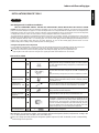 5
5
-
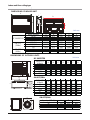 6
6
-
 7
7
-
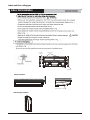 8
8
-
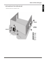 9
9
-
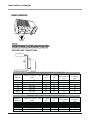 10
10
-
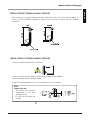 11
11
-
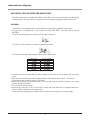 12
12
-
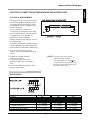 13
13
-
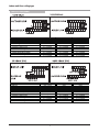 14
14
-
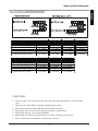 15
15
-
 16
16
-
 17
17
-
 18
18
-
 19
19
-
 20
20
-
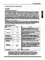 21
21
-
 22
22
-
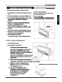 23
23
-
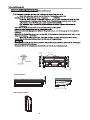 24
24
-
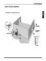 25
25
-
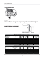 26
26
-
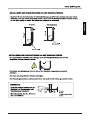 27
27
-
 28
28
-
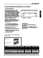 29
29
-
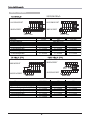 30
30
-
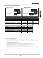 31
31
-
 32
32
-
 33
33
-
 34
34
-
 35
35
-
 36
36
-
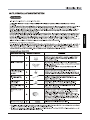 37
37
-
 38
38
-
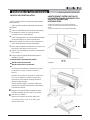 39
39
-
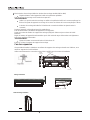 40
40
-
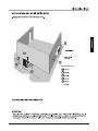 41
41
-
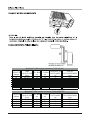 42
42
-
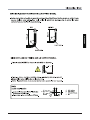 43
43
-
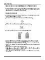 44
44
-
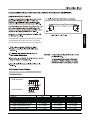 45
45
-
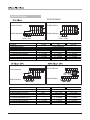 46
46
-
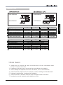 47
47
-
 48
48
-
 49
49
-
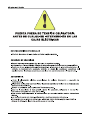 50
50
-
 51
51
-
 52
52
-
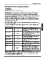 53
53
-
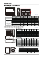 54
54
-
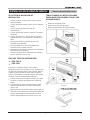 55
55
-
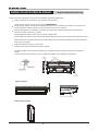 56
56
-
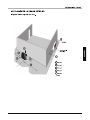 57
57
-
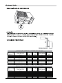 58
58
-
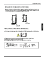 59
59
-
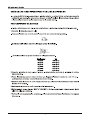 60
60
-
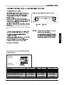 61
61
-
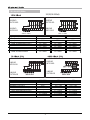 62
62
-
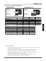 63
63
-
 64
64
-
 65
65
-
 66
66
-
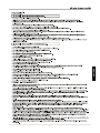 67
67
-
 68
68
-
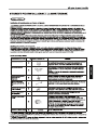 69
69
-
 70
70
-
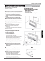 71
71
-
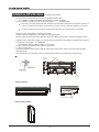 72
72
-
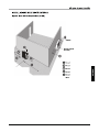 73
73
-
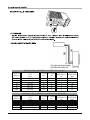 74
74
-
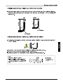 75
75
-
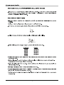 76
76
-
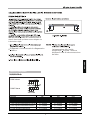 77
77
-
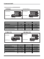 78
78
-
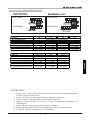 79
79
-
 80
80
-
 81
81
-
 82
82
-
 83
83
-
 84
84
-
 85
85
-
 86
86
-
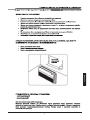 87
87
-
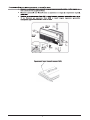 88
88
-
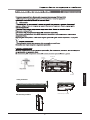 89
89
-
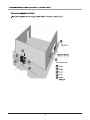 90
90
-
 91
91
-
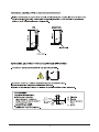 92
92
-
 93
93
-
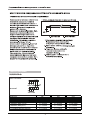 94
94
-
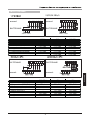 95
95
-
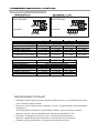 96
96


Airwell Aqu@Scop Advance R410A Guía de instalación
- Tipo
- Guía de instalación
En otros idiomas
Documentos relacionados
Otros documentos
-
Toshiba MMD-AP0071SPH El manual del propietario
-
Toshiba MMU-AP0071YH Manual de usuario
-
LG LMU600HV.AWGBEUS Guía de instalación
-
Friedrich MR24DY3JMA Instrucciones de operación
-
-
mundoclima Serie MUSTR-H9 “Ceiling Floor Full Inverter H9” Guía de instalación
-
LG A3UW36GFAB.AWGTLAR Manual de usuario
-
LG A3UW24GFAB El manual del propietario
-
LG PM09EP.NSJ Manual de usuario
-