Panasonic TH80LFB70E Instrucciones de operación
- Tipo
- Instrucciones de operación

Model No.
TH-80LFB70E
Operating Instructions
Touch Screen LCD Display (for business use)
For more detailed instructions, refer to the Operating
Instructions on the CD-ROM.
Contents
•
Important Safety Notice .............................2
•
Safety Precautions .....................................3
•
Accessories ................................................7
•
Connections ...............................................9
•
Power On / Off .........................................11
•
Basic Controls ..........................................13
•
Specifi cations ...........................................15
Please read these instructions before operating your set
and retain them for future reference.
English
Español

2
English
Important Safety Notice
WARNING
1) To prevent damage which may result in fi re or shock hazard, do not expose this appliance to dripping
or splashing.
Do not place containers with water (fl ower vase, cups, cosmetics, etc.) above the set. (including on
shelves above, etc.)
No naked fl ame sources, such as lighted candles, should be placed on / above the set.
2) To prevent electric shock, do not remove cover. No user serviceable parts inside. Refer servicing to qualifi ed
service personnel.
3) Do not remove the earthing pin on the power plug. This apparatus is equipped with a three pin earthing-type
power plug. This plug will only fi t an earthing-type power outlet. This is a safety feature. If you are unable to
insert the plug into the outlet, contact an electrician.
Do not defeat the purpose of the earthing plug.
4) To prevent electric shock, ensure the earthing pin on the AC cord power plug is securely connected.
CAUTION
This appliance is intended for use in environments which are relatively free of electromagnetic fi elds.
Using this appliance near sources of strong electromagnetic fi elds or where electrical noise may overlap with the
input signals could cause the picture and sound to wobble or cause interference such as noise to appear.
To avoid the possibility of harm to this appliance, keep it away from sources of strong electromagnetic fi elds.
IMPORTANT: THE MOULDED PLUG
IMPORTANT: THE MOULDED PLUG
FOR YOUR SAFETY, PLEASE READ THE FOLLOWING TEXT CAREFULLY.
This display is supplied with a moulded three pin mains plug for your safety and convenience. A 10 amp fuse is
fi tted in this plug. Shall the fuse need to be replaced, please ensure that the replacement fuse has a rating of 10
amps and that it is approved by ASTA or BSI to BS1362.
Check for the ASTA mark
ASA
or the BSI mark on the body of the fuse.
If the plug contains a removable fuse cover, you must ensure that it is refi tted when the fuse is replaced.
If you lose the fuse cover the plug must not be used until a replacement cover is obtained.
A replacement fuse cover can be purchased from your local Panasonic dealer.
Do not cut off the mains plug.
Do not use any other type of mains lead except the one supplied with this display.
The supplied mains lead and moulded plug are designed to be used with this display to avoid
interference and for your safety.
If the socket outlet in your home is not suitable, get it changed by a qualifi ed electrician.
If the plug or mains lead becomes damaged, purchase a replacement from an authorized dealer.
WARNING : — THIS DISPLAY MUST BE EARTHED.
How to replace the fuse.
Open the fuse compartment with a screwdriver and replace the fuse.
Note:
Image retention may occur. If you display a still picture for an extended period, the image might remain on the
screen. However, it will disappear after a while.

3
English
Safety Precautions
Always be sure to ask a qualifi ed technician to carry out set-up.
Small parts can present choking hazard if accidentally swallowed. Keep small parts away from young children. Discard
unneeded small parts and other objects, including packaging materials and plastic bags/sheets to prevent them from
being played with by young children, creating the potential risk of suffocation.
Do not place the Display on sloped or unstable surfaces, and ensure that the Display does not hang over the
edge of the base.
• The Display may fall off or tip over.
Do not place any objects on top of the Display.
• If water is spills onto the Display or foreign objects get inside it, a short-circuit may occur which could result in fi re
or electric shock. If any foreign objects get inside the Display, please consult your local Panasonic dealer.
Transport only in upright position!
• Transporting the unit with its display panel facing upright or downward may cause damage to the internal
circuitry.
Ventilation should not be impeded by covering the ventilation openings with items such as newspapers, table
cloths and curtains.
For suffi cient ventilation;
Leave a space of 10 cm or more at the top, left and right, and 7 cm or more at the rear, and also keep the
space between the bottom of the display and the fl oor surface.
Cautions for Wall Installation
• Wall installation should be performed by an installation professional. Installing the Display incorrectly may lead to
an accident that results in death or serious injury. Use the specifi ed accessories.
• If you terminate the use of the Display on the wall, ask a professional to remove the Display as soon as possible.
Do not install the product to a place where the product is exposed to direct sunlight.
• If the screen is exposed to direct sunlight, the liquid crystal panel may have adverse effect.
WARNING
Setup
This LCD Display is for use only with the following optional accessories. Use with any other type of optional
accessories may cause instability which could result in the possibility of injury.
(All of the following accessories are manufactured by Panasonic Corporation.)
• Pedestal .................................................................................... TY-ST65P20
• Mobile stand for Display ............................................................ TY-ST80LF70
• Wall-hanging bracket (vertical) .................................................. TY-WK70PV50
• BNC Dual Video Terminal Board ............................................... TY-FB9BD
• HD-SDI Terminal Board ............................................................. TY-FB9HD
• HD-SDI Terminal Board with audio ........................................... TY-FB10HD
• Dual Link HD-SDI Terminal Board ............................................. TY-FB11DHD
• Dual HDMI Terminal Board ....................................................... TY-FB10HMD
• DVI-D Terminal Board ............................................................... TY-FB11DD
• Digital Interface Box .................................................................. ET-YFB100G

4
English
Safety Precautions
When using the LCD Display
The Display is designed to operate on 220 - 240 V AC, 50/60 Hz.
Do not cover the ventilation holes.
• Doing so may cause the Display to overheat, which can cause fi re or damage to the Display.
Do not stick any foreign objects into the Display.
• Do not insert any metal or fl ammable objects into the ventilations holes or drop them onto the Display, as doing so
can cause fi re or electric shock.
Do not remove the cover or modify it in any way.
• High voltages which can cause severe electric shocks are present inside the Display. For any inspection, adjustment
and repair work, please contact your local Panasonic dealer.
Ensure that the mains plug is easily accessible.
An apparatus with CLASS I construction shall be connected to a mains socket outlet with a protective earthing
connection.
Do not use any power supply cord other than that provided with this unit.
• Doing so may cause fi re or electric shocks.
Securely insert the power supply plug as far as it will go.
• If the plug is not fully inserted, heat may be generated which could cause fi re. If the plug is damaged or the wall
socket is loose, they shall not be used.
Do not handle the power supply plug with wet hands.
• Doing so may cause electric shocks.
Do not do anything that may damage the power cable. When disconnecting the power cable, pull on the plug
body, not the cable.
• Do not damage the cable, make any modifi cations to it, place heavy objects on top of it, heat it, place it near any
hot objects, twist it, bend it excessively or pull it. To do so may cause fi re and electric shock. If the power cable is
damaged, have it repaired at your local Panasonic dealer.
Do not remove covers and NEVER modify the Display yourself
• Do not remove the rear cover as live parts are accessible when it is removed. There are no user serviceable parts
inside. (High-voltage components may cause serious electrical shock.)
• Have the Display checked, adjusted, or repaired at your local Panasonic dealer.
Keep the Pen Stand fi xing screw and washer out of reach of children to prevent swallowing.
If the Display is not going to be used for any prolonged length of time, unplug the power supply plug from
the wall outlet.
To prevent the spread of fi re, keep candles or other open fl ames away from this product at all times.
If problems occur during use
If a problem occurs (such as no picture or no sound), or if smoke or an abnormal odour starts to come out
from the Display, immediately unplug the power supply plug from the wall outlet.
• If you continue to use the Display in this condition, fi re or electric shock could result. After checking that the smoke
has stopped, contact your local Panasonic dealer so that the necessary repairs can be made. Repairing the Display
yourself is extremely dangerous, and shall never be done.
If water or foreign objects get inside the Display, if the Display is dropped, or if the cabinet becomes damages,
disconnect the power supply plug immediately.
• A short circuit may occur, which could cause fi re. Contact your local Panasonic dealer for any repairs that need to
be made.

5
English
Safety Precautions
CAUTION
When using the LCD Display
Do not bring your hands, face or objects close to the ventilation holes of the Display.
• Heated air comes out from the ventilation holes at the top of Display will be hot. Do not bring your hands or face,
or objects which cannot withstand heat, close to this port, otherwise burns or deformation could result.
Be sure to disconnect all cables before moving the Display.
• If the Display is moved while some of the cables are still connected, the cables may become damaged, and fi re or
electric shock could result.
Disconnect the power supply plug from the wall socket as a safety precaution before carrying out any
cleaning.
• Electric shocks can result if this is not done.
Clean the power cable regularly to prevent it becoming dusty.
• If dust built up on the power cord plug, the resultant humidity can damage the insulation, which could result in fi re.
Pull the power cord plug out from the wall outlet and wipe the mains lead with a dry cloth.
Do not burn or breakup batteries.
• Batteries must not be exposed to excessive heat such as sunshine, fi re or the like.
Cleaning and maintenance
The front of the display panel has been specially treated. Wipe the panel surface gently using only a cleaning
cloth or a soft, lint-free cloth.
• If the surface is particularly dirty, wipe with a soft, lint-free cloth which has been soaked in pure water or water in
which neutral detergent has been diluted 100 times, and then wipe it evenly with a dry cloth of the same type until
the surface is dry.
• Do not scratch or hit the surface of the panel with fi ngernails or other hard objects, otherwise the surface may
become damaged. Furthermore, avoid contact with volatile substances such as insect sprays, solvents and thinner,
otherwise the quality of the surface may be adversely affected.
If the cabinet becomes dirty, wipe it with a soft, dry cloth.
• If the cabinet is particularly dirty, soak the cloth in water to which a small amount of neutral detergent has been
added and then wring the cloth dry. Use this cloth to wipe the cabinet, and then wipe it dry with a dry cloth.
• Do not allow any detergent to come into direct contact with the surface of the Display. If water droplets get inside
the unit, operating problems may result.
• Avoid contact with volatile substances such as insect sprays, solvents and thinner, otherwise the quality of the
cabinet surface may be adversely affected or the coating may peel off. Furthermore, do not leave it for long periods
in contact with articles made from rubber or PVC.
Wipe off dirt on the IR transmission part with soft cloth.
• Wipe off dirt on the IR transmission part with soft cloth once a day.
If malfunction is due to dirt on the IR transmission part, simply wiping it off lightly can recover the performance.
If dirt is sticky, wipe it off with cloth wrung out of neutral detergent diluted with water and then wipe the part with
dry cloth.
Usage of a chemical cloth
• Do not use a chemical cloth for the panel surface.
• Follow the instructions for the chemical cloth to use it for the cabinet.
Ask your dealer to clean the inside at least once a year.
• Dust accumulated inside may interfere with the infrared beam for touch detection, resulting in poor performance.
Ask your dealer to clean the inside at least once a year.

6
English
Safety Precautions
Touch panel
Carefully observe the following instructions as the display has an optical touch panel.
Do not expose the display to direct sunlight or strong light source during use.
• Otherwise malfunction may occur since the optical touch panel of the display uses infrared rays.
After turning on the power of the display, do not touch the IR transmission part
and the screen until any image is displayed.
• Otherwise the touched part may be detected as defective elements, resulting in
abnormal operation. If this occurred, turn the display off and then on.
Always use a fi nger or the supplied pen to operate the touch panel. Do not use a hard or sharp tip such as
nail, ball-point pen, and pencil.
When using any other infrared device, keep a distance to prevent erroneous operation.
Wired LAN
When setting up the Display at a place, where electric statistic occurs often, take a suffi cient anti-static
measure before start using.
• When the Display is used at a location, where static electricity occurs often, such as on a carpet, communications
of the DIGITAL LINK and the wired LAN are disconnected more often. In that case, remove static electricity and
the noise source that may cause problems with an antistatic mat, and re-connect the DIGITAL LINK and the wired
LAN.
• In rare cases, the LAN connection is disabled due to static electricity or noise. In that case, turn off the power of
the Display and the connected devices once and then re-turn on the power. Connect the DIGITAL LINK and the
LAN.
The Display may not work properly due to strong radiowave from the broadcast station or the radio.
• If there is any facility or equipment, which outputs strong radiowave, near the installation location, set up the
Display at a location suffi ciently far from the source of the radiowave. Or, wrap the LAN cable connected to the
DIGITAL LINK terminal by using a piece of metal foil or a metal pipe, of which is grounded at both ends.
IR transmission part
LCD Display
Declaration of Conformity (DoC)
“Hereby, Panasonic Corporation declares that this Display is in compliance with the essential
requirements and other relevant provisions of the Directive 1999/5/EC.”
If you want to get a copy of the original DoC of this Display, please visit the following website:
http://www.doc.panasonic.de
Authorized Representative:
Panasonic Testing Centre
Panasonic Marketing Europe GmbH
Winsbergring 15, 22525 Hamburg, Germany
This Display is intended to be used in the following countries.
Albania, Austria, Belgium, Bulgaria, Cyprus, Czech Republic, Denmark, Estonia, Finland, France,
Germany, Greece, Hungary, Italy, Iceland, Latvia, Lithuania, Luxembourg, Malta, Netherlands, Norway,
Poland, Portugal, Romania, Slovakia, Slovenia, Spain, Sweden, Switzerland, Turkey, United Kingdom
The wireless LAN feature of this Display shall exclusively be used inside buildings.

Clamper × 1
TMME289
Batteries for the Remote
Control Transmitter
(R6 (UM3) Size × 2)
Remote Control
Transmitter
N2QAYB000691
Operating
Instruction book
Check that you have the accessories and items shown
Software CD-ROM × 1
Pen × 4
Eraser × 1 Pen Stand × 1
(see page 8)
Screw × 2
(see page 8)
Washer × 2
(see page 8)
USB cable × 1 Ferrite core × 2
J0KG00000014
Cable tie × 2
TMM17499
Power supply cord
7
English
Accessories Supply
Accessories
Contents in the CD-ROM
The contents below are included in the supplied CD-ROM.
Instruction
(PDF)
Operating Instructions - Display Operations
Operating Instructions - Network Operations
Operating Instructions - Wireless Manager ME
Software license GNU GENERAL PUBLIC LICENSE
GNU LESSER GENERAL PUBLIC LICENSE
Software WhiteBoard Software (Windows) Allows the display to be used as whiteboard.
You can run the software directly from external
storage without installing it in your computer.
Wireless Manager ME (Windows/Mac) Allows the image on the computer screen to be
sent wirelessly or via wired LAN.
Switch the input to Panasonic APPLICATION
before use. For more details, see the instruction
manual of Wireless Manager ME.
Attention
Store small parts in an appropriate manner, and keep them away from young children.
Use the Ferrite cores
to comply with the EMC
standard. (see page 9)

1 Remove a screw from the back cover.
4 Mount the Pen Stand with the supplied screw.
The Pen Stand can hold four pens and one Eraser.
2 Peel the paper backing off the supplied washer.
3 Paste the washer to a screw hole for the pen stand.
Any of the hole A to D can be used to fi x the pen stand.
A
B
C
D
Washer (supplied)
Pen Stand
(supplied)
Screw
(supplied)
Pen Stand
8
English
+
-
+
-
Remote Control Batteries
Requires two R6 batteries.
1. Pull and hold the hook, then open
the battery cover.
2. Insert batteries - note correct
polarity (+ and -).
3. Replace the cover.
Helpful Hint:
For frequent remote control users, replace old batteries with Alkaline
batteries for longer life.
Precaution on battery use
Incorrect installation can cause battery leakage and corrosion that will damage the remote control transmitter.
Disposal of batteries should be in an environment-friendly manner.
Observe the following precaution:
1. Batteries shall always be replaced as a pair. Always use new batteries when replacing the old set.
2. Do not combine a used battery with a new one.
3. Do not mix battery types (example: “Zinc Carbon” with “Alkaline”).
4. Do not attempt to charge, short-circuit, disassemble, heat or burn used batteries.
5.
Battery replacement is necessary when remote control acts sporadically or stops operating the Display set.
6. Do not burn or breakup batteries.
7. Batteries must not be exposed to excessive heat such as sunshine, fi re or the like.
“R6 (UM3)” size
Accessories
Mounting Pen Stand
The supplied Pen Stand can be mounted on one of the nine positions on the back of the Display.

9
English
Connections
Plug the AC cord into the display unit.
Plug the AC cord until it clicks.
Note:
Make sure that the AC cord is locked on
both the left and right sides.
AC cord fi xing
Unplug the AC cord
Unplug the AC cord pressing the
two knobs.
Note:
When disconnecting the AC cord, be
absolutely sure to disconnect the AC
cord plug at the socket outlet fi rst.
Using the clamper
Secure any excess cables with clamper as required.
Note:
One clamper is supplied with this unit. In case of securing cables at four positions, please purchase it separately.
If you need more clampers, purchase them from your dealer. (Available from the customer service)
1
2
Attach the clamper
To remove from the unit:
Keep pushing
both side snaps
hole
Bundle the cables
snaps
hooks
Set the
tip in the
hooks
To loosen:
Keep
pushing
the knob
knob
Insert the clamper
in a hole.
AC cord connection and fi xing, cable fi xing
How to use the Ferrite core
Stereo mini plug (M3)
PC with DVI-D
video out
Shared with PC IN.
Less than
5 cm
Ferrite core
(supplied)
DVI-video cable (Within 5 m)
Less than
5 cm
Installing the Ferrite core
Pull back the tabs
(in two places)
1.
Open the
Ferrite core
2.
Route the
cable through
and close
3.
Fix the Ferrite
core with the
cable tie
4.

10
English
Video equipment connection
Connections
Please use 8 Ω/10 W speaker.
Speaker connection
Red
Black
Red
Black
1
While pressing the lever,
insert the core wire.
2
Return the lever.
AUDIO 1 IN:
Audio input terminal
shared with VIDEO
and COMPONENT/
RGB IN.
PC IN:
PC Input Terminal
Connect to video terminal of PC or
equipment with Y,
P
B
(C
B
)
and
P
R
(C
R
)
output.
DVI-D IN: DVI-D Input Terminal
LAN, DIGITAL LINK*
Connect to a DIGITAL LINK input terminal network
to control the Display. Alternatively, connect to a
device that sends video and audio signals via the
DIGITAL LINK terminal.
SERIAL:
Serial Control Terminal.
Control the Display
by connecting to PC.
AV IN (VIDEO): Composite Video Input Terminal
COMPONENT/RGB IN: Component/RGB Video
Input Terminal
*
DIGITAL LINK is technology that enables signals such as audio and video to be transmitted using twisted pair cables.
For details, see the Operating Instructions - “Network Operations”.
AV IN (HDMI 1, HDMI 2): HDMI Input
Terminal
Connect to video equipment such as
VCR or DVD player.
AUDIO 2 IN:
Audio input terminal
shared with DVI-D IN
and PC IN.
PC OUT:
Video signals being
reproduced on the display
are output to another sub
monitor as PC video signals.
SLOT: Terminal board (optional accessories) insert slot
(see page 3)
Note:
The upper side slot is for terminal board with 2-slot width. The
terminal board with 1-slot width does not function when installed in
the upper side slot.

11
English
Power On / Off
Press the button on the remote control to turn the Display off.
Power Indicator: Red (standby)
Press the button on the remote control to turn the Display on.
Power Indicator: Green
Turn the power to the Display off by pressing the switch on the unit, when
the Display is on or in standby mode.
Note:
During operation of the power management function, the power indicator turns
orange in the power off state.
Connecting the plug to the Wall Outlet
Notes:
• Main plug types vary between countries. The power
plug shown at right may, therefore, not be the type
fi tted to your set.
• When disconnecting the AC cord, be absolutely sure
to disconnect the AC cord plug at the socket outlet
fi rst.
Press the Power switch on the Display to turn the set
on: Power-On.
Power Indicator: Green
[Starting up the touch screen and network]
It takes some time for the touch screen and network
to start up just after the power is turned on.
During that time, “Touch Screen Settings”, “Network
Settings” in the “Setup” menu is grayed out and
cannot be set.
Connecting the AC cord plug to the Display.
Power switch
Power Indicator Remote Control Sensor

Set
Day
MON
18:00
Time
Day/Time Settings
Time
MON 99:99
Set
Day
TUE
18:00Time
Day/Time Settings
Time TUE 99:99
OSD Language
English (UK)
Deutsch
Français
Italiano
Español
ENGLISH (US)
Русский
12
English
Power On / Off
When fi rst switching on the unit
Following screen will be displayed when the unit is turned on for the fi rst time.
Use the remote control to make the settings. Pressing the buttons on the main unit or multi-touch operation will
not work.
Notes:
• Once the items are set, the screens won't be displayed when switching on the unit next time.
• After the setting, the items can be changed in the following menus.
OSD Language
Day/Time Settings
Power ON message
The following message may be displayed when turning the unit power ON:
No activity power off Precautions
‘No activity power off’ is enabled.
If “No activity power off” in Setup menu is set to “Enable”, a warning message is displayed every time the
power is turned ON.
Power Management Information
Last turn off due to ‘Power management’.
If “Power management” is functioned, an information message is displayed every time the power is turned ON.
These message displays can be set with the following menu: Options menu
Power On Message (No activity power off)
Power On Message (Power Management)
OSD Language
Day/Time Settings
1
Select the
language.
2
Set.
1
Select “Day”
or “Time”.
2
Setup “Day”
or “Time”.
1
Select “Set”.
2
Set.
WhiteBoard Startup screen
Now Loading...
WhiteBoard
When the power is turned ON with the Input switch of the WHITEBOARD, the built-in WhiteBoard starts up.
Touch screen connection status display
When not connected to a computer via USB
Initializing Touch Screen...
When connected to a computer via USB
Touch Screen connected to external device.
Touch Screen detected.
Touch operation of the display is possible after this
message appears.

13
English
INPUT
MENU
VOL
ENTER/
+
/
-
/
Basic Controls
MENU Screen ON / OFF
Each time the MENU button is pressed, the menu screen will switch.
Normal Viewing Picture
Sound Pos. /Size
Setup
Volume Adjustment
Volume Up “+” Down “–”
When the menu screen is displayed:
“+” : press to move the cursor up
“–” : press to move the cursor down
Remote control
sensor
Main Power On / Off Switch
Brightness Sensor
Detects the brightness in the viewing environment.
Main Unit
Power Indicator
The Power Indicator will light.
• Power-OFF .... Indicator not illuminated (The unit will still
consume some power as long as the power
cord is still inserted into the wall outlet.)
• Standby ........Red
Orange (When “Slot power” is set to “On”
and Terminal Board is installed.)
Orange (Depending on the type of the function board
installed, when the power is supplied to the slot)
Orange (When “Control I/F Select” is set to “DIGITAL
LINK/LAN” or “Wireless Network Standby” is set to “On”.
Refer to “Operating Instructions, Network Operations”)
Orange (When “Quick Launch” is set to “On”.)
• Power-ON ...... Green
• HDMI1 Power management
HDMI2 Power management
......................... Orange (With HDMI1 or HDMI2 input signal.)
* These functions are not supported by TH-80LFB70E.
• PC Power management (DPMS)
......................... Orange (With PC input signal.)
• DVI-D Power management
......................... Orange (With DVI input signal.)
Note:
If the power indicator is orange, power consumption during standby
is generally larger than that of when the power indicator is red.
Enter / Aspect button
INPUT button (INPUT signal selection)
SLOT: Terminal board (optional accessories) insert
slot (see page 3)
Note:
The upper side slot is for terminal board with 2-slot
width. The terminal board with 1-slot width does not
function when installed in the upper side slot.
Touch panel IR transmission part
Installed on the four sides of the display panel.
USB (VIEWER): Connect to USB memory.
USB (TOUCH):
When using the “WhiteBoard
Software” from the supplied CD-ROM,
connect the computer via USB cable.

14
English
Basic Controls
Remote Control Transmitter
Digital Zoom
1
2
PC
4:3
♪ COMPONENT
Memory name: MEMORY2
Off timer
90min
3
4
10:00
Standby (ON / OFF) button
The Display must fi rst be plugged into
the wall outlet and turned on at the
power switch (see page 11).
Press this button to turn the Display
On, from Standby mode. Press
it again to turn the Display Off to
Standby mode.
ACTION button
Press to make selections.
ASPECT button
Press to adjust the aspect.
POS./SIZE button
PICTURE button
Sound mute On / Off
Press this button to mute the
sound.
Press again to reactivate sound.
Sound is also reactivated when
power is turned off or volume level
is changed.
N button
POSITION buttons
INPUT button
Press to select Input signal
sequentially.
ECO MODE (ECO)
Press to change the ECO MODE
setup status.
FUNCTION buttons (FUNCTION)
AUTO SETUP button
Automatically adjusts the position/
size of the screen.
SET UP button
SOUND button
Volume Adjustment
Press the Volume Up “+” or Down “–”
button to increase or decrease the
sound volume level.
R button
Press the R button to return to
previous menu screen.
OFF TIMER button
The Display can be preset to switch to stand-by
after a fi xed period. The setting changes to 30
minutes, 60 minutes, 90 minutes and 0 minutes
(off timer cancelled) each time the button is
pressed.
30 min 60 min
0 min (Cancel)
90 min
When three minutes remain, “Off timer 3 min”
will fl ash.
The off timer is cancelled if a power interruption
occurs.
RECALL button
Press the “RECALL” button to display
the current system status.
1
Input label
2
Aspect mode
Audio input
Profi le name
3
Off timer
The off timer indicator is
displayed only when the off
timer has been set.
4
Clock display

15
English
Specifi cations
TH-80LFB70E
Power Source 220 - 240 V AC, 50/60 Hz
Power Consumption
Power on 350 W
Stand-by condition 0.5 W
Power off condition 0.3 W
LCD Display panel 80-inch VA panel (LED backlight), 16:9 aspect ratio
Screen size 1,771 mm (W) × 996 mm (H) × 2,032 mm (diagonal)
(No.of pixels) 2,073,600 (1,920 (W) ×1,080 (H))
[5,760 × 1,080 dots]
Operating condition
Temperature 0 °C - 40 °C
Humidity 20 % - 80 % (no condensation)
Applicable signals
Colour System NTSC, PAL, PAL60, SECAM, Modifi ed NTSC
Scanning format 525 (480) / 60i · 60p, 625 (575) / 50i · 50p, 750 (720) / 60p · 50p, 1125 (1080) / 60i · 60p · 50i ·
50p · 24p · 25p · 30p · 24psF, 1250 (1080) / 50i
PC signals VGA, SVGA, XGA, SXGA
UXGA ···· (compressed)
Horizontal scanning frequency 15 - 110 kHz
Vertical scanning frequency 48 - 120 Hz
Connection terminals
AV IN VIDEO
AUDIO 1 IN
BNC
Stereo mini jack (M3) × 1
1.0 Vp-p (75 Ω)
0.5 Vrms, Shared with COMPONENT/RGB IN
HDMI 1
HDMI 2
TYPE A Connector × 2
COMPONENT/RGB IN
Y/G
P
B/CB/B
P
R/CR/R
AUDIO 1 IN
BNC
BNC
BNC
Stereo mini jack (M3) × 1
with sync 1.0 Vp-p (75 Ω)
0.7 Vp-p (75 Ω)
0.7 Vp-p (75 Ω)
0.5 Vrms, Shared with VIDEO
DVI-D IN
AUDIO 2 IN
DVI-D 24 Pin
Content Protection
Stereo mini jack (M3) × 1
Compliance with DVI Revision 1.0
Compatible with HDCP 1.1
0.5 Vrms, Shared with PC IN
PC IN
AUDIO 2 IN
High-Density Mini D-sub 15 Pin
Stereo mini jack (M3) × 1
Y or G with sync 1.0 Vp-p (75 Ω)
Y or G without sync 0.7 Vp-p (75 Ω)
P
B/CB/B: 0.7 Vp-p (75 Ω)
P
R/CR/R: 0.7 Vp-p (75 Ω)
HD/VD: 1.0 - 5.0 Vp-p (high impedance)
0.5 Vrms, Shared with DVI-D IN
SERIAL External Control Terminal
D-sub 9 Pin RS-232C compatible
PC OUT R: 0.7 Vp-p (75 Ω)
G: 0.7 Vp-p (75 Ω)
B: 0.7 Vp-p (75 Ω)
HD/VD: 1.0 - 5.0 Vp-p
USB (VIEWER) TYPE A USB connector
USB (TOUCH) TYPE B USB connector
DIGITAL LINK / LAN For RJ45 network and DIGITAL LINK connections, compatible with PJLink™
Communication method: RJ45 100BASE-TX
EXT SP 8 Ω, 20 W [10 W + 10 W] (10 % THD)
Sound
Speakers 120 mm × 40 mm × 2 pcs
Audio Output 20 W [10 W + 10 W] (10 % THD)
Dimensions (W × H × D) 1,868 mm × 1,093 mm × 104 mm
Mass (weight) approx. 84.0 kg net
Notes:
• Design and specifi cations are subject to change without notice. Mass and dimensions shown are approximate.
• This equipment complies with the EMC standards listed below.
EN55022, EN55024, EN61000-3-2, EN61000-3-3.

Information for Users on Collection and Disposal of Old Equipment and used Batteries
These symbols on the products, packaging, and/or accompanying documents mean that used
electrical and electronic products and batteries should not be mixed with general household waste.
For proper treatment, recovery and recycling of old products and used batteries, please take them to
applicable collection points, in accordance with your national legislation and the Directives
2002/96/EC and 2006/66/EC.
By disposing of these products and batteries correctly, you will help to save valuable resources and
prevent any potential negative effects on human health and the environment which could otherwise
arise from inappropriate waste handling.
For more information about collection and recycling of old products and batteries, please contact your
local municipality, your waste disposal service or the point of sale where you purchased the items.
Penalties may be applicable for incorrect disposal of this waste, in accordance with national
legislation.
For business users in the European Union
If you wish to discard electrical and electronic equipment, please contact your dealer or supplier for
further information.
[Information on Disposal in other Countries outside the European Union]
These symbols are only valid in the European Union. If you wish to discard these items, please
contact your local authorities or dealer and ask for the correct method of disposal.
Note for the battery symbol (bottom two symbol examples):
This symbol might be used in combination with a chemical symbol. In this case it complies with the
requirement set by the Directive for the chemical involved.
Customer’s Record
The model number and serial number of this product can be found on its rear panel. You should note this serial
number in the space provided below and retain this book, plus your purchase receipt, as a permanent record of your
purchase to aid in identifi cation in the event of theft or loss, and for Warranty Service purposes.
Model Number Serial Number
Web Site : http://panasonic.net
© Panasonic Corporation 2014
Printed in the Czech Republic
TQB0E2448U-G
Trademark Credits
• VGA is a trademark of International Business Machines Corporation.
• Microsoft
®
, Windows
®
, Windows Vista
®
, and Internet Explorer
®
are the registered trademarks or trademarks of
Microsoft Corporation in the United States and/or other countries.
• Macintosh, Mac, Mac OS, OS X and Safari are the trademarks of Apple Inc. registered in the United States
and other countries.
• SVGA, XGA, SXGA and UXGA are registered trademarks of the Video Electronics Standard Association.
Even if no special notation has been made of company or product trademarks, these trademarks have been
fully respected.
• HDMI, the HDMI Logo, and High-Defi nition Multimedia Interface are trademarks or registered trademarks of
HDMI Licensing LLC in the United States and other countries.
• RoomView, Crestron RoomView and Fusion RV are registered trademarks of Crestron Electronics, Inc, and
Crestron Connected is the trademark of Crestron Electronics, Inc.
• Miracast is a trademark of Wi-Fi Alliance.
• Android is a registered trademark of Google Inc.
• iPad, iPhone, and iPod touch are trademarks of Apple Inc., registered in the U.S. and other countries.
English

Número de modelo
Manual de instrucciones
Pantalla táctil LCD (para uso comercial)
Para obtener instrucciones más detalladas, consulte las
instrucciones de manejo contenidas en el CD-ROM.
Indice
•
Advertencias importantes para su seguridad
...2
•
Precauciones para su seguridad ...............3
•
Accesorios ..................................................7
•
Conexiones ................................................9
•
Encendido/apagado de la alimentación ...11
•
Controles básicos ....................................13
•
Especifi caciones ......................................15
Antes de utilizar este producto, lea cuidadosamente este
manual de instrucciones y consérvelo para futuras consultas.
TH-80LFB70E
Español

2
Español
Advertencias importantes para su
seguridad
ADVERTENCIA
1) Para evitar daños que pudieran conducir a un incendio o a una descarga eléctrica, no exponga este
aparato a goteos ni salpicaduras.
No ponga recipientes con agua (fl oreros, tazas, cosméticos, etc.) encima del aparato (incluyendo los
estantes que estén encima de él, etc.)
No coloque fuentes de llama, como velas encendidas, en el aparato.
2) Para evitar descargas eléctricas, no desmonte la cubierta. No hay piezas que el usuario pueda reparar por sí
mismo. Acuda a un técnico de servicio cualifi cado para cualquier problema de servicio.
3) No desmonte la patilla de tierra del enchufe eléctrico. Este aparato tiene un enchufe eléctrico de tipo tres patillas
con conexión a tierra. Este enchufe sólo puede conectarse en tomas con conexión a tierra. Es un detalle para
su seguridad, si no puede conectar este enchufe en su tomas, consulte con un electricista.
No elimine la protección del enchufe con conexión a tierra.
4) Para impedir las descargas eléctricas, asegúrese de que la patilla de puesta a tierra de la clavija del cable de
alimentación de CA esté fi rmemente conectada.
PRECAUCIÓN
Este aparato fue diseñado para utilizar en ambientes relativamente libres de campos electromagnéticos.
El uso de este aparato cerca de fuentes de campos electromagnéticos fuertes o donde el ruido eléctrico puede
superponerse a las señales de entrada, puede hacer que la imagen y el sonido oscilen o tengan interferencias
tales como ruidos.
Para evitar la posibilidad de dañar el aparato, manténgalo alejado de fuentes de campos electromagnéticos
fuertes.
Marcas comerciales y registradas
• VGA es una marca comercial de International Business Machines Corporation.
• Microsoft
®
, Windows
®
, Windows Vista
®
, e Internet Explorer
®
son las marcas registradas de Microsoft Corporation
en los Estados Unidos y otros países.
• Macintosh, Mac, Mac OS, OS X, y Safari son marcas registradas de Apple Inc. registradas en los Estados Unidos
y otros países.
• SVGA, XGA, SXGA y UXGA son marcas registradas de Video Electronics Standard Association.
Aunque no se mencionen especialmente marcas comerciales de compañías o productos, tales marcas
comerciales están plenamente reconocidas.
• HDMI, el logotipo HDMI y High-Defi nition Multimedia Interface son marcas comerciales o marcas comerciales
registradas de HDMI Licensing LLC en Estados Unidos y otros países.
• RoomView, Crestron RoomView y Fusion RV son marcas comerciales registradas de Crestron Electronics, Inc,
y Crestron Connected es la marca comercial de Crestron Electronics, Inc.
• Miracast es una marca comercial de Wi-Fi Alliance.
• Android es una marca registrada de Google Inc.
• iPad, iPhone e iPod touch son marcas comerciales de Apple Inc. registradas en los EE.UU. y otros países.
Nota:
Puede producirse la retención de imagen. Si muestra una imagen fi ja durante mucho tiempo, ésta puede que
permanezca en la pantalla. Sin embargo, la imagen desaparecerá después de pasar un rato.

3
Español
Precauciones para su seguridad
ADVERTENCIA
Instalación
Esta pantalla LCD sólo se puede utilizar con los siguientes accesorios opcionales. El uso con cualquier otro
tipo de accesorios opcionales puede causar inestabilidad y terminar provocando daños.
(Panasonic Corporation fabrica todos los accesorios siguientes.)
• Pedestal ...................................................................................... TY-ST65P20
• Pedestal móvil para la pantalla ................................................... TY-ST80LF70
• Abrazadera de suspensión de pared (vertical) ............................TY-WK70PV50
• Tarjeta de terminales de vídeo dual BNC ....................................TY-FB9BD
• Tarjeta de terminales HD-SDI ......................................................TY-FB9HD
• Tarjeta de terminales HD-SDI con audio .....................................TY-FB10HD
• Tarjeta de terminales HD-SDI Dual Link ......................................TY-FB11DHD
• Tarjeta de terminales HDMI doble ...............................................TY-FB10HMD
• Placa de terminal DVI-D ..............................................................TY-FB11DD
• Caja de interfaz digital .................................................................ET-YFB100G
Solicite ayuda de un técnico califi cado para realizar la instalación.
Las partes pequeñas pueden presentar un peligro ya que la persona puede asfi xiarse si dichas partes se tragan
accidentalmente. En consecuencia, mantenga estas partes fuera del alcance de los niños pequeños. Tire las partes
pequeñas y objetos, incluyendo materiales para embalaje y bolsas/papeles de plástico, para que los niños pequeños
no jueguen, ya que si lo hicieran corren un riesgo potencial de sofocación.
No instale la pantalla sobre superfi cies inclinadas o poco estables y asegúrese de que la pantalla no
sobresale de la base.
• La pantalla puede caerse o darse vuelta.
No coloque objetos encima de la pantalla.
• Si se derrama agua en la pantalla o entran objetos extraños en su interior, se puede provocar un cortocircuito que
causará fuego o descarga eléctrica. Si entran objetos extraños en el interior de la pantalla, consulte con su tienda
local de Panasonic.
¡Transporte solamente en posición vertical!
• Transportar la unidad con su pantalla hacia arriba o hacia abajo puede dañar el sistema de circuitos interno.
No se debe impedir la ventilación cubriendo las bocas de ventilación con objetos como pueden ser por
ejemplo periódicos, manteles y cortinas.
Para una ventilación sufi ciente;
Deje un espacio de
10 cm
o más por la parte superior, derecha e izquierda, y
7 cm
o más por la parte trasera,
y mantenga también el espacio entre la parte inferior de la pantalla y la superfi cie del suelo.
Precauciones para la instalación en pared
• La instalación en una pared debe ser realizada por un montador profesional. Una instalación incorrecta de la pantalla
puede provocar un accidente y ocasionar lesiones graves o incluso la muerte. Emplee los accesorios opcionales
especifi cados.
• Si deja de utilizar la pantalla sobre la pared, solicite a un profesional que la retire lo antes posible.
No instale el producto en un lugar donde esté expuesto a la luz directa del sol.
• La exposición directa de la pantalla a la luz de sol puede afectar negativamente al panel de cristal líquido.

4
Español
Precauciones para su seguridad
Cuando utilice la pantalla LCD
La pantalla está diseñada para funcionar a 220 - 240 V CA, 50/60 Hz.
No cubra los orifi cios de ventilación.
• La pantalla puede calentarse excesivamente provocado fuego o daños en la Pantalla.
No introduzca materias extrañas en el interior de la pantalla.
• No introduzca objetos de metal o infl amables por los orifi cios de ventilación ni los deje caer encima de la pantalla
ya que pueden provocar fuego o una descarga eléctrica.
No desmonte o modifi que la cubierta.
• Hay alta tensión eléctrica en el interior del aparato que puede provocar una fuerte descarga eléctrica. Para cualquier
trabajo de inspección, ajuste o reparación, llame a su tienda local de Panasonic.
Asegure que haya un acceso fácil hacia el enchufe del cable de alimentación.
Un aparato de fabricación clase I deberá conectarse a una toma de corriente que disponga de una conexión
a tierra de protección.
Con esta unidad no utilice ningún otro cable eléctrico que no sea el suministrado.
• De lo contrario podría producirse un incendio o descargas eléctricas.
Inserte completamente el enchufe del cable eléctrico.
• Si el enchufe no ha entrado completamente puede generar calor y ser el origen de un incendio. Si el enchufe está
dañado o la toma de corriente está fl oja, no los utilice.
No toque el enchufe del cable eléctrico con las manos mojadas.
• Puede recibir una descarga eléctrica.
No haga nada que pueda dañar el cable eléctrico. Cuando desenchufe el cable eléctrico, sujete del enchufe
y no el cable.
• No dañe el cable eléctrico, no lo modifi que ni coloque objetos pesados encima, ni coloque cerca de objetos que
desprendan calor, no tuerza ni tire excesivamente del mismo. Esto puede provocar un fuego o descarga eléctrica.
Si el cable eléctrico está dañado, solicite la reparación en su tienda local de Panasonic.
No retire las cubiertas y no modifi que NUNCA la pantalla usted mismo
•
No retire la cubierta trasera, ya que al retirarla quedarán accesibles partes por las que pasa corriente. No hay piezas que el
usuario pueda reparar por sí mismo. (Los componentes de alta tensión pueden provocar descargas eléctricas peligrosas).
• Verifi que, ajuste o repare la pantalla en su tienda local de Panasonic.
Mantenga fuera del alcance de los niños el tornillo de fi jación del soporte para lápiz y la arandela, para evitar que
se los traguen.
Si no se utiliza la pantalla durante un largo período de tiempo, desenchufe el cable eléctrico de la toma de
corriente.
Para impedir un incendio no deje velas u otras fuentes del fuego abierto cerca del televisor.
Si se producen problemas durante el uso
Si se produce un problema (por ejemplo falta la imagen o sonido), o si sale humo o hay olores no normales
de la pantalla, desenchufe inmediatamente el cable eléctrico de la toma de corriente.
• Si sigue utilizando la pantalla en estas condiciones, puede provocar un fuego o descarga eléctrica. Después de
comprobar que ha dejado de salir humo, llame a su tienda local de Panasonic para solicitar las reparaciones
necesarias. No repare la pantalla por su cuenta ya que es muy peligroso.
Si entra agua o materias extrañas en el interior de la pantalla, si se ha caído la pantalla o si el mueble
exterior está dañado, desenchufe inmediatamente el cable eléctrico.
• Puede provocar un cortocircuito que inicie un incendio. Llame a su tienda local de Panasonic para hacer las
reparaciones necesarias.

5
Español
Precauciones para su seguridad
PRECAUCIÓN
Cuando utilice la pantalla LCD
No acerque sus manos, rostro u otros objetos cerca de los orifi cios de ventilación de la pantalla.
• El aire que sale de los orifi cios de ventilación y de la parte superior de la pantalla está caliente. No acerque sus
manos, cara u objetos que no puedan soportar el calor, a estos orifi cios porque puede quemarse.
Desconecte todos los cables antes de mover la pantalla.
• Si fuera necesario mover la pantalla a otro lugar y se dejan algunos cables conectados, éstos pueden dañarse,
provocar un incendio o una descarga eléctrica.
Desenchufe el cable eléctrico de la toma de corriente como medida de seguridad antes de realizar una
limpieza.
• Puede sufrir una descarga eléctrica si no lo hace.
Limpie el cable eléctrico a intervalos regulares para evitar que se cubra por el polvo.
• Si hay acumulación de polvo en el enchufe del cable eléctrico, la humedad puede acumularse y dañar el aislamiento,
provocando un incendio. Desenchufe el cable eléctrico de la toma de corriente y limpie con un paño seco.
No queme ni rompa las pilas.
• No exponga las baterías al calor excesivo como radiación solar, fuego o similares.
Limpieza y mantenimiento
El frente del panel de la pantalla ha recibido un tratamiento especial. Limpie suavemente la superfi cie del
panel utilizando el paño de pulido o un paño suave.
• Si la superfi cie está particularmente sucia, límpiela pasando un paño blando y sin pelusa que haya sido humedecido
en agua pura o en agua en la que se haya diluido detergente neutro 100 veces, y luego pase uniformemente un
paño seco del mismo tipo hasta que quede seca la superfi cie.
• No raye o golpee la superfi cie del panel con sus uñas u otros objetos duros ya que la superfi cie puede dañarse.
Además, evite el contacto con sustancias volátiles tales como rociadores de insecticida, disolventes y diluyentes
de pintura, de lo contrario puede verse afectada la calidad de la superfi cie.
Si el mueble se ensucia, limpie con un paño suave y seco.
• Si el mueble está muy sucio, empape el paño en agua mezclada con una pequeña cantidad de detergente neutro
y escurra el paño hasta eliminar el agua. Utilice el paño para limpiar el mueble y seque frotando con un paño
seco.
• No permita que el detergente entre en contacto directo con la superfi cie de la pantalla. Si las gotas de agua entran
en el interior del aparato, pueden surgir problemas en el funcionamiento.
• Evite el contacto con sustancias volátiles tales como rociadores de insecticida, disolventes y diluyentes de pintura
debido a que puede verse afectada la superfi cie del mueble y puede desprenderse el revestimiento. Tampoco deje
la superfi cie por mucho tiempo en contacto con artículos de caucho o PVC.
Limpie con un paño suave la suciedad de la parte que transmite los infrarrojos.
• Limpie una vez al día, con un paño suave, la suciedad de la parte que transmite los infrarrojos.
Si se producen problemas de funcionamiento porque hay suciedad en la parte que transmite los infrarrojos,
bastará con limpiarla un poco para restablecer el funcionamiento normal. Si la suciedad es persistente, límpiela
con un paño humedecido en una solución de detergente neutral en agua bien escurrido, y después seque esa
parte con un paño seco.
Uso de un paño con productos químicos.
• No utilice un paño con productos químicos para la superfi cie del panel.
• Siga las instrucciones del paño con productos químicos para usarlo con el mueble.
Solicite en su tienda la limpieza del interior al menos una vez al año.
• El polvo acumulado en el interior puede interferir con los rayos infrarrojos para la detección táctil, provocando un
funcionamiento defi ciente. Solicite en su tienda la limpieza del interior al menos una vez al año.

6
Español
Precauciones para su seguridad
Panel táctil
Tenga muy en cuenta las instrucciones siguientes, ya que la pantalla dispone de un panel táctil óptico.
No exponga la pantalla a la luz solar directa ni a fuentes de luz intensas durante su uso.
• De lo contrario, se pueden producir problemas de funcionamiento, ya que el panel táctil óptico de la pantalla utiliza
rayos infrarrojos.
Después de encender la alimentación de la pantalla, no toque la parte
que transmite los infrarrojos ni la pantalla hasta que se muestre alguna
imagen.
• De lo contrario, la parte que toque podría ser detectada como un elemento
defectuoso, lo que provocaría un funcionamiento anómalo. Si ese fuera el
caso, apague la pantalla y vuelva a encenderla.
Para usar el panel táctil, utilice siempre un dedo o el puntero que se suministra. No utilice objetos que
tengan la punta dura o afi lada como una uña, un bolígrafo o un lápiz.
Cuando utilice cualquier otro dispositivo con infrarrojos, mantenga una cierta distancia para evitar un
funcionamiento erróneo.
Parte que transmite los infrarrojos
LAN alámbrica
Si instala la pantalla en un sitio con mucha electricidad estática, asegúrese de tomar las medidas
necesarias antes de empezar a utilizarla.
• Al utilizar la pantalla en un sitio con mucha electricidad estática, como una alfombra, las interrupciones de la
comunicación entre el sistema DIGITAL LINK y la LAN con cable son más habituales. En este caso, elimine la
electricidad estática y la fuente de ruido causante de los problemas con una alfombra antiestática y vuelva a
conectar el sistema DIGITAL LINK y la LAN con cable.
• Aunque es poco habitual, a veces la conexión LAN se desactiva a causa de la electricidad estática o del ruido.
En este caso, apague la alimentación de la pantalla y los dispositivos conectados una vez y, después, vuelva a
encenderla. Conecte el sistema DIGITAL LINK y la LAN.
Es posible que la pantalla funcione mal si recibe ondas radioeléctricas fuertes de la estación emisora o la
radio.
• Si hay algún centro o equipo que emita ondas radioeléctricas fuertes cerca del sitio de instalación, instale la
pantalla en un lugar sufi cientemente alejado de la fuente de las ondas radioeléctricas. O bien envuelva el cable
LAN conectado al terminal DIGITAL LINK con un trozo de papel de aluminio o un tubo metálico conectado a tierra
por ambos extremos.

7
Español
Accesorios
Accesorios suministrados
Abrazadera × 1
TMME289
Pilas para el transmisor de
mando a distancia
(tamaño R6 (UM3) × 2)
Transmisor del
mando a distancia
N2QAYB000691
Manual de
instrucciones
Compruebe que ha recibido todos los accesorios indicados
CD-ROM del software × 1
Contenido del CD-ROM
En el CD-ROM que se suministra, se incluyen los siguientes contenidos:
Instrucciones
(PDF)
Manual de instrucciones - Operaciones con la pantalla
Manual de instrucciones - Operaciones de red
Manual de instrucciones - Wireless Manager ME
Licencia de software GNU GENERAL PUBLIC LICENSE
GNU LESSER GENERAL PUBLIC LICENSE
Software
WhiteBoard Software (Windows) Permite utilizar la pantalla como una pizarra.
Puede ejecutar el software directamente desde
el almacenamiento externo sin instalarlo en su
ordenador.
Wireless Manager ME (Windows/Mac) Permite enviar la imagen de la pantalla del
ordenador de forma inalámbrica o a través de
una LAN conectada.
Antes de su uso, cambie la entrada a Panasonic
APPLICATION. Para obtener más información,
vea el Manual de instrucciones de Wireless
Manager ME.
Atención
Almacene las partes pequeñas de forma correcta y manténgalas alejadas de niños pequeños.
Lápiz × 4
Borrador × 1 Soporte para lápiz × 1
(vea la página 8)
Tornillo × 2
(vea la página 8)
Arandela × 2
(vea la página 8)
Cable USB × 1 Núcleo de ferrita × 2
J0KG00000014
Brida para cables × 2
TMM17499
Utilice el núcleo de ferrita
para cumplir la norma EMC.
(vea la página 9)
Cable de alimentación eléctrica

8
Español
Accesorios
Pilas del mando a distancia
+
-
+
-
Se necesitan dos pilas R6.
1. Tire del gancho para abrir la tapa
de las pilas.
2.
Coloque las pilas correctamente con
las polaridades (+) y (–) indicadas.
3. Vuelva a colocar la tapa.
Consejo útil:
Para las personas que utilizan el mando a distancia con frecuencia, se
recomienda reemplazar las pilas usadas por pilas alcalinas que duran más.
Precaución relacionada con el uso de las pilas
La instalación mal hecha puede causar fugas de electrólito y corrosión, lo que estropeará el transmisor de mando a
distancia. Las pilas deben desecharse por medios ecológicos.
Tome las precauciones siguientes:
1. Las pilas deberán reemplazarse siempre juntas. Cuando reemplace pilas usadas, utilice siempre pilas nuevas.
2. No mezcle una pila usada con una nueva.
3. No mezcle distintos tipos de pilas (por ejemplo: pilas de carbón de zinc con alcalinas).
4. No intente cargar, cortocircuitar, desarmar, calentar o quemar las pilas usadas.
5.
El reemplazo de las pilas es necesario cuando el mando a distancia funciona esporádicamente o no puede controlar la pantalla.
6. No queme ni rompa las pilas.
7. No exponga las baterías al calor excesivo como radiación solar, fuego o similares.
Tamaño “R6 (UM3)”
Montaje del soporte para lápiz
El soporte para lápiz que se suministra se puede instalar en una de las nueve posiciones de la parte trasera
de la pantalla.
1 Retire un tornillo de la cubierta trasera.
4
Instale el soporte para lápiz con el tornillo que se suministra.
El soporte para lápiz puede sostener cuatro lápices
y un borrador.
2 Despegue el papel de la parte posterior de la arandela que
se suministra.
3 Pegue la arandela en un tornillo del soporte para lápiz.
Se puede utilizar cualquier orifi cio del A al D para fi jar el
soporte para lápiz.
A
B
C
D
Arandela
(se suministra)
Soporte para lápiz
(se suministra)
Tornillo
(se suministra)
Soporte para lápiz

Conecte el cable de CA a la unidad de pantalla.
Al conectar el cable de CA, presione
hasta que suene click.
Nota:
Asegúrese de que el cable de alimentación de CA esté
sujetado en ambos lados, el derecho y el izquierdo.
Fijación del cable de alimentación de CA
Desenchufe el cable de CA.
Desenchufe el cable de CA
presionando los dos ganchos.
Nota:
Cuando desconecte el cable de alimentación
de CA, asegúrese absolutamente de
desconectar primero la clavija del cable de
alimentación de CA de la toma de corriente.
1
2
Utilización de la abrazadera
Sujete el exceso de los cables con una abrazadera según sea necesario.
Nota:
Con esta unidad se suministra una abrazadera. Para fi jar los cables en cuatro posiciones, adquiérala por separado.
Si necesita más bridas de sujeción, debe adquirirlas en su tienda. (Disponibles a través de Atención al Cliente)
Coloque la abrazadera
Para retirar de la unidad:
Mantenga empujados
los cierres de ambos
lados
agujero
Ate los cables
cierres
ganchos
Ponga la
punta en los
ganchos
Para afl ojar:
Mantenga
empujada
la perilla
perilla
Inserte la abrazadera
en el agujero.
Conexiones
Cable de conexión a CA y elemento de fi jación, elemento de fi jación para el cable
Cómo utilizar el núcleo de ferrita
Miniclavija estéreo (M3)
PC con salida
de video DVI-D
Compartida con PC IN.
Menos de
5 cm
Núcleo de ferrita
(suministrado)
Cable de vídeo DVI (entre 5 m)
Menos de
5 cm
Instalación del núcleo de ferrita
Retire las lengüetas
(en los dos lugares)
1.
Abra el núcleo
de ferrita
2.
Pase el cable
y cierre
3.
Fije el núcleo
de ferrita con la
brida para cables
4.
9
Español

10
Español
Conexiones
Conexión al equipo de vídeo
Utilice un altavoz 8 Ω/10 W.
Conexión al altavoz
Rojo
Negro
Rojo
Negro
1
Inserte el núcleo de alambre tensado
a la vez que presiona la palanca.
2
Devuelva la
palanca a su lugar.
AUDIO 1 IN:
Terminal de entrada
de audio compartida
con VIDEO y
COMPONENT/RGB
IN.
PC IN: Terminal de entrada de PC
Conecte al terminal de vídeo del PC
o equipo con la salida Y, PB(CB) y
PR(CR).
DVI-D IN: Terminal de entrada DVI-D
LAN, DIGITAL LINK*
Conecte a una red de terminales de entrada
DIGITAL LINK para controlar la pantalla.
Como alternativa, conecte a un dispositivo que
envía señales de vídeo y de audio mediante un
terminal DIGITAL LINK.
SERIAL:
Terminal de control
en serie.
Control de la
pantalla mediante
su conexión al PC.
AV IN (VIDEO): Terminal de entrada de vídeo
compuesto
COMPONENT/RGB IN:
Terminal de entrada de vídeo
componente/RGB
* DIGITAL LINK es una tecnología que permite que se envíen señales, como p. ej. de audio y de vídeo, usando
cables de par trenzado. Para obtener más información, vea el Manual de instrucciones - “Operaciones de red”.
AV IN (HDMI 1, HDMI 2): Terminal
de entrada HDMI
Conecte a un equipo de vídeo, como
una videograbadora o reproductor de
DVD.
AUDIO 2 IN:
Terminal de entrada de
audio compartida con
DVI-D IN y PC IN.
PC OUT:
Las señales de vídeo que
se estén reproduciendo en
la pantalla se envían a otro
monitor secundario, como
las señales de vídeo del PC.
SLOT: Ranura de inserción de la tarjeta de terminales (accesorios
opcionales) (vea la página 3)
Nota:
La ranura de la parte superior es para la tarjeta de terminales de 2
ranuras de ancho. La tarjeta de terminales de 1 ranura de ancho
no funciona cuando se instala en la ranura de la parte superior.

11
Español
Interruptor de
encendido
Piloto de
encendido
Sensor de control remoto
Encendido/apagado de la alimentación
Presione la tecla de espera del mando a distancia para apagar la pantalla.
Piloto de encendido: Rojo (espera)
Presione la tecla de espera del mando a distancia para encender la pantalla.
Piloto de encendido: Verde
Desconecte la alimentación de la pantalla presionando el interruptor de la
unidad si la pantalla está encendida o en modo de espera.
Nota:
Durante la operación de gestión de la alimentación, el indicador de la alimentación
se pone naranja en el estado de alimentación desconectada.
Conexión de la clavija a una toma de corriente
Notas:
• Los tipos de clavijas cambian según los países. La
clavija de alimentación mostrada a la derecha puede,
por lo tanto, no ser la misma que se encuentra en su
aparato.
• Cuando desconecte el cable de alimentación de CA,
asegúrese absolutamente de desconectar primero la
clavija del cable de alimentación de CA de la toma de
corriente.
Presione el interruptor principal de la pantalla de para
encender el aparato.
Piloto de encendido: Verde
[Inicio de la pantalla táctil y de la red]
La pantalla táctil y la red tardan un tiempo en iniciarse
después de haber encendido la alimentación.
Durante ese tiempo, la “Ajustes de pantalla táctil”,
“Ajustes de red” en el menú de “Confi guración” está
atenuada y no se puede ajustar.
Conexión de la clavija del cable de alimentación de CA a la pantalla.

Ajustar
Día de la semana
Lu
18:00
HORA ACTUAL
Puesta de HORA ACTUAL
HORA ACTUAL Lu 99:99
Ajustar
Día de la semana
Ma
18:00HORA ACTUAL
Puesta de HORA ACTUAL
HORA ACTUAL Ma 99:99
Cuando encienda por primera vez la unidad
Cuando encienda la unidad por primera vez se visualizará la pantalla siguiente.
Utilice el mando a distancia para realizar los ajustes. Si pulsa los botones de la unidad principal o las operaciones
multitáctiles, no funcionarán
Notas:
•
Una vez establecidos los elementos, la pantalla no se visualizará cuando se encienda la unidad la próxima vez.
• Después de hacer el ajuste, los elementos podrán cambiarse en los menús siguientes.
Idioma de OSD
Puesta de HORA ACTUAL
Mensaje de encendido
Al encender la unidad, puede aparecer el mensaje siguiente:
Precauciones con la opción Apagado si no hay actividad
“Apagado si no hay actividad” está activado.
Si en la opción “Apagado si no hay actividad” de los menús de Confi guración selecciona “Activar”, se mostrará
un mensaje de advertencia cada vez que encienda la pantalla.
La visualización de este mensaje se puede configurar mediante el siguiente menú: Menú Options
Power On Message (No activity
power off)
Power On Message (Power
Management)
Idioma de OSD Puesta de HORA ACTUAL
Pantalla de inicio de E
asy Whiteboard
Now Loading...
WhiteBoard
Cuando la alimentación se ENCIENDE con el interruptor de entrada de WHITEBOARD, se inicia la pizarra
(WhiteBoard) integrada.
Información sobre gestión de la alimentación
Último apagado debido a “Energía monitor”.
Si “Energía monitor” está establecido en “Encendido” se mostrará un mensaje de advertencia cada vez que se
encienda la alimentación.
Idioma de OSD
English (UK)
Deutsch
Français
Italiano
Español
ENGLISH (US)
Русский
1
Seleccione
el idioma.
2
Ajuste.
1
Seleccione “Día de
la semana” o “HORA
ACTUAL”.
2
Ponga “Día de la
semana” o “HORA
ACTUAL”.
1
Seleccione
“Ajustar”.
2
Ajuste.
Pantalla de estado de conexión de la pantalla táctil
Cuando no se ha conectado a un ordenador a través de USB
Inicializando pantalla táctil...
Cuando se ha conectado a un ordenador a
través de USB
Pantalla táctil conectada a dispositivo externo.
Pantalla táctil detectada.
Las operaciones táctiles con la pantalla serán
posibles después de que aparezca este mensaje.
12
Español
Encendido/apagado de la alimentación

13
Español
INPUT
MENU
VOL
ENTER/
+
/
-
/
Controles básicos
Encendido/Apagado de la pantalla MENÚ
Cada vez que se pulsa el botón MENU, la pantalla de menú se conmuta.
Visión normal Imagen Confi guración
Sonido Pos. /Tamaño
Ajuste de volumen
Subida “+” y bajada “-” del volumen
Cuando se visualice la pantalla del menú:
“+”: presione para mover el cursor hacia arriba
“–”: presione para mover el cursor hacia abajo
Sensor de control
remoto
Interruptor principal
Sensor de brillo
Capta el brillo en el entorno de la pantalla.
Unidad principal
Piloto de encendido
Se enciende el piloto de funcionamiento.
•
Desconectado
...
El indicador está apagado (La unidad consume algo
de energía siempre que el cable de alimentación se
mantiene conectado a la toma de corriente.)
• Espera .......... Rojo
Naranja (Cuando “Slot power” está en “On” y
la tarjeta de terminales está instalada.)
Naranja (Dependiendo del tipo de tarjeta de función instalada,
cuando se suministra alimentación de corriente a la ranura)
Naranja (Cuando “Seleccionar interfaz de control” está
ajustado como “DIGITAL LINK/LAN” o Cuando “Red
inalámbrica en reposo” está ajustado como “Encendido”.
Consulte el “Manual de instrucciones, Operaciones de red”)
Naranja (cuando “Inicio rápido” está en “On” o
en “On”.)
• Conectado ..... Verde
• HDMI1 Energía monitor
HDMI2 Energía monitor
......................
Naranja (Con las señales de entrada HDMI1 o HDMI2.)
* Estas funciones no son compatibles con TH-80LFB70E.
• PC Energía monitor (DPMS)
....................... Naranja (Con la señal de entrada de PC.)
• DVI-D Energía monitor
.......................
Naranja (Con la señal de entrada DVI.)
Nota:
Si el indicador de la alimentación está en naranja, el consumo de
energía durante el modo de espera es generalmente mayor que el
que tiene lugar cuando el indicador de la alimentación está en rojo.
Botón de introducción/aspecto
Tecla INPUT (Selección de la señal de entrada)
SLOT: Ranura de inserción de la tarjeta de terminales
(accesorios opcionales) (vea la página 3)
Nota:
La ranura del lado superior es para la tarjeta de
terminales de 2 ranuras de ancho. La tarjeta de
terminales de 1 ranura de ancho no funciona cuando
se instala en la ranura del lado superior.
Parte del panel táctil que transmite los infrarrojos
Instalado en los cuatro lados del panel de la pantalla.
USB (VIEWER): Conexión de una memoria USB.
USB (TOUCH): Cuando utilice el “WhiteBoard
Software” del CD-ROM que se
suministra, conéctese al ordenador
con el cable USB.

14
Español
Controles básicos
Transmisor del mando a distancia
Tecla de espera (Encendido/Apagado)
La pantalla debe conectarse primero
en el tomacorriente y con el interruptor
principal (vea la página 11).
Pulse este botón para encender la
pantalla de estando ésta en el modo de
espera. Pulse de nuevo el botón para
apagar la pantalla y ponerla en el modo
de espera.
Tecla de ACTION
Presiónelo para seleccionar y hacer ajustes.
Tecla ASPECT
Presione para ajustar el aspecto.
Tecla POS./SIZE
Tecla PICTURE
Silenciamiento de sonido
Presione esta tecla para silenciar el sonido.
Presiónela de nuevo para reactivar el
sonido. El sonido se reactiva también
cuando se apaga la alimentación o se
cambia el nivel del sonido.
Tecla N
Teclas de posición
Tecla INPUT
Presione para seleccionar la señal de
entrada de forma secuencial.
Modo ECO (ECO)
Pulse para cambiar el estado de
confi guración de Modo ECO.
Botones FUNCTION (FUNCTION)
Zoom digital
Tecla AUTO SETUP
Ajusta automáticamente la
posición y el tamaño de la
pantalla.
Tecla SET UP
Tecla SOUND
Ajuste de volumen
Presione la tecla de volumen
arriba “+” o abajo “–” para hacer
subir o bajar el nivel de volumen
del sonido.
Tecla R
Presione el botón R para volver a
la pantalla de menú anterior.
Tecla OFF TIMER
La pantalla de puede programarse para cambiar
al modo de espera después de un intervalo
predeterminado. El ajuste cambia a 30 minutos,
60 minutos, 90 minutos y 0 minutos (se cancela el
temporizador) cada vez que se presiona la tecla.
Cuando quedan tres minutos, destella
“Temporizador 3 min”.
El temporizador queda cancelado cuando se
produce un corte eléctrico.
Tecla de RECALL
Presione la tecla de “RECALL”
para que aparezca el estado del
sistema actual.
1
Etiqueta de entrada
2
Modo de relación de ASPECT
Entrada de audio
Nombre del perfi l
3
Apagado de temporizador
El indicador del temporizador
aparece sólo cuando se ha
seleccionado el temporizador.
4
Visualización del reloj
30 min
60 min
0 min (Cancelación)
90 min
1
2
PC
Temporizador
90min
3
4
10:00
4:3
COMPONENT
Memory name: MEMORY2

15
Español
Especifi caciones
TH-80LFB70E
Fuente de alimentación 220 - 240 V AC, 50/60 Hz
Fuente de consumo
Máximo 350 W
Estado de espera
0,5 W
Estado de corriente
desconectada
0,3 W
Panel de pantalla LCD Panel VA de 80 pulgadas (con retroiluminación por LED),
relación de aspecto 16:9
Tamaño de pantalla 1.771 mm (An.) × 996 mm (Al.) × 2.032 mm (diagonal)
(Número de pixeles) 2.073.600 (1.920 (W) ×1.080 (H))
[5.760 × 1.080 puntos]
Condiciones de funcionamiento
Temperatura 0 °C - 40 °C
Humedad 20 % - 80 % (sin condensación)
Señales aplicables
Sistema de color NTSC, PAL, PAL60, SECAM, NTSC modifi cado
Formato de exploración 525 (480) / 60i · 60p, 625 (575) / 50i · 50p, 750 (720) / 60p · 50p, 1125 (1080) / 60i · 60p · 50i ·
50p · 24p · 25p · 30p · 24psF, 1250 (1080) / 50i
Señales PC VGA, SVGA, XGA, SXGA
UXGA ···· (comprimido)
Frecuencia de exploración horizontal 15 - 110 kHz
Frecuencia de exploración vertical 48 - 120 Hz
Terminales de conexión
AV IN VIDEO
AUDIO 1 IN
BNC
Miniclavija estéreo (M3) × 1
1,0 Vp-p (75 Ω)
0,5 Vrms, Compartida con COMPONENT/RGB IN
HDMI1
HDMI2
Conector Tipo A × 2
COMPONENT/RGB IN
Y/G
P
B/CB/B
P
R/CR/R
AUDIO 1 IN
BNC
BNC
BNC
Miniclavija estéreo (M3) × 1
con sincronización 1,0 Vp-p (75 Ω)
0,7 Vp-p (75 Ω)
0,7 Vp-p (75 Ω)
0,5 Vrms,
Compartida con
VIDEO
DVI-D IN
AUDIO 2 IN
DVI-D de 24 contactos
Protección del contenido
Miniclavija estéreo (M3) × 1
Cumple con DVI Revisión 1.0
Compatible con HDCP 1.1
0,5 Vrms, Compartida con PC IN
PC IN
AUDIO 2 IN
Alta densidad, conector Mini D-sub de 15
contactos
Miniclavija estéreo (M3) × 1
Y o G con sincronización 1,0 Vp-p (75 Ω)
Y o G sin sincronización 0,7 Vp-p (75 Ω)
P
B/CB/B: 0,7 Vp-p (75 Ω)
P
R/CR/R: 0,7 Vp-p (75 Ω)
HD/VD: 1,0 - 5,0 Vp-p (alta impedancia)
0,5 Vrms, Compartida con DVI-D IN
SERIAL Terminal de control exterior
Conector D-sub de 9 contactos Compatible con RS-232C
PC OUT R: 0,7 Vp-p (75 Ω)
G: 0,7 Vp-p (75 Ω)
B: 0,7 Vp-p (75 Ω)
HD/VD: 1,0 - 5,0 Vp-p
USB (VIEWER) Conector USB TIPO A
USB (TOUCH) Conector USB TIPO B
DIGITAL LINK / LAN Para las conexiones de red RJ45 y DIGITAL LINK, compatible con PJLink™
Método de comunicación: RJ45 100BASE-TX
EXT SP 8 Ω, 20 W [10 W + 10 W] (10 % THD)
Sonido
Altavoces 120 mm × 40 mm × 2 piezas
Salida de audio 20 W [10 W + 10 W] (10 % THD)
Dimensiones (An. × Al. × Prof.)
1.868 mm × 1.093 mm × 104 mm
Masa (Peso) Aprox. 84,0 kg netos
Notas:
• El diseño y especifi caciones están sujetos a cambios sin previo aviso. El Masa y dimensiones son aproximados.
• Este equipo cumple con las normas EMC en la lista a continuación.
EN55022, EN55024, EN61000-3-2, EN61000-3-3.

Información para Usuarios sobre la Recolección y Eliminación de aparatos viejos y baterías usadas
Estos símbolos en los productos, embalajes y/o documentos adjuntos, significan que los aparatos
eléctricos y electrónicos y las baterías no deberían ser mezclados con los desechos domésticos.
Para el tratamiento apropiado, la recuperación y el reciclado de aparatos viejos y baterías usadas,
por favor, observe las normas de recolección aplicables, de acuerdo a su legislación nacional y a las
Directivas 2002/96/CE y 2006/66/CE.
Al desechar estos aparatos y baterías correctamente, Usted estará ayudando a preservar recursos
valiosos y a prevenir cualquier potencial efecto negativo sobre la salud de la humanidad y el medio
ambiente que, de lo contrario, podría surgir de un manejo inapropiado de los residuos.
Para mayor información sobre la recolección y el reciclado de aparatos y baterías viejos, por favor,
contacte a su comunidad local, su servicio de eliminación de residuos o al comercio donde adquirió
estos aparatos.
Podrán aplicarse penas por la eliminación incorrecta de estos residuos, de acuerdo a la legislación
nacional.
Para usuarios empresariales en la Unión Europea
Si usted desea descartar aparatos eléctricos y electrónicos, por favor contacte a su distribuidor o
proveedor a fin de obtener mayor información.
[Informacion sobre la Eliminación en otros Países fuera de la Unión Europea]
Estos símbolos sólo son válidos dentro de la Unión Europea. Si desea desechar estos objetos, por
favor contacte con sus autoridades locales o distribuidor y consulte por el método correcto de
eliminación.
Nota sobre el símbolo de la bateria (abajo, dos ejemplos de símbolos):
Este símbolo puede ser usado en combinación con un símbolo químico. En este caso, el mismo
cumple con los requerimientos establecidos por la Directiva para los químicos involucrados.
Registro del cliente
El número de modelo y número de serie de este producto están en la cubierta trasera. Debe anotar este número de
serie en el espacio a continuación y guardar este libro junto con el recibo de compra como registro permanente de
su compra para ayudar a identifi carlo en el caso de robo o pérdida y para el servicio bajo garantía.
Número de modelo Número de serie
Sitio Web : http://panasonic.net
©
Panasonic Corporation 2014
Impreso en la República Checa
Pantalla LCD
Declaración de conformidad (DoC)
“Por la presente, Panasonic Corporation declara que esta pantalla es de conformidad con los requisitos
sustanciales y con las disposiciones pertinentes de la Directiva 1999/5/EC”.
Si quiere obtener una copia de la declaración de conformidad original (DoC) de esta pantalla, por favor,
visite el sitio web siguiente:
http://www.doc.panasonic.de
Representante autorizado:
Panasonic Testing Centre
Panasonic Marketing Europe GmbH
Winsbergring 15, 22525 Hamburg, Germany
Esta pantalla está pensada para su uso en los siguientes países.
Albania, Alemania, Austria, Bélgica, Bulgaria, Chipre, Dinamarca, Eslovaquia, Eslovenia, España,
Estonia, Finlandia, Francia, Grecia, Hungría, Islandia, Italia, Letonia, Lituania, Luxemburgo, Malta,
Noruega, Países Bajos, Polonia, Portugal, República Checa, Rumanía, Suecia, Suiza, Turquía, Reino
Unido
La característica LAN inalámbrica de esta pantalla debe utilizarse exclusivamente en el interior de los
edifi cios.
TQB0E2448E-G
Español
-
 1
1
-
 2
2
-
 3
3
-
 4
4
-
 5
5
-
 6
6
-
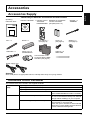 7
7
-
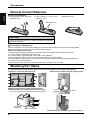 8
8
-
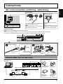 9
9
-
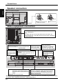 10
10
-
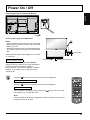 11
11
-
 12
12
-
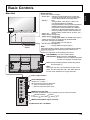 13
13
-
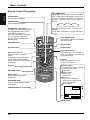 14
14
-
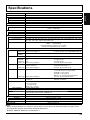 15
15
-
 16
16
-
 17
17
-
 18
18
-
 19
19
-
 20
20
-
 21
21
-
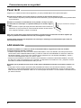 22
22
-
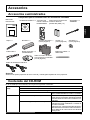 23
23
-
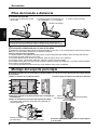 24
24
-
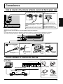 25
25
-
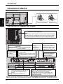 26
26
-
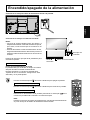 27
27
-
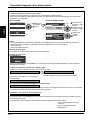 28
28
-
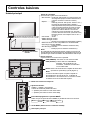 29
29
-
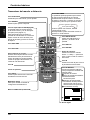 30
30
-
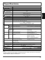 31
31
-
 32
32


Panasonic TH80LFB70E Instrucciones de operación
- Tipo
- Instrucciones de operación
En otros idiomas
Documentos relacionados
-
Panasonic TH50LFB70E Instrucciones de operación
-
Panasonic TH65LFB70U Instrucciones de operación
-
Panasonic TH50LFC70E Instrucciones de operación
-
-
Panasonic TH42PF50E El manual del propietario
-
-
-
-
-
Otros documentos
-
Sharp PN60TA3 El manual del propietario
-
AG Neovo TX-42 Manual de usuario
-
Sharp PN-L703A Guía de instalación
-
Sharp LL-S242A-W El manual del propietario
-
-
Ectaco C-Pen TS1 Digital Scanner Guía de inicio rápido
-
Canvys MD-DFM19-ENDO Ficha de datos
-
Insta360 Link AI-Powered 4K Webcam Guía del usuario