Loctite 883976 Instrucciones de operación
- Tipo
- Instrucciones de operación

EQUIPMENT
Operation Manual
Loctite
Digital Syringe Dispenser
Part Number 883976
Benutzerhandbuch
Loctite
Digitales
Kartuschendosiergerät
Artikelnummer 883976
Manual de operación
Loctite
Dosificador
digital tipo jeringa
Número de parte 883976

2
Table of Contents 2
1. Safety - Please Observe the Following 3
1.1 Emphasized Sections
1.2 For Your Safety
1.3 Unpacking and Inspection
1.4 Items Supplied
2 Description 4
3 Technical Data 6
4 Installation 6
5 Operation 7
5.1 Set up Instructions
Manual Mode
5.2 Dispense Cycle Setting
Time Mode
Incremental Mode with Teach Function
Cycle Counter Reset
6 Troubleshooting 10
7 Maintenance & Operational Tips 11
8 Accessories and Spare Parts 11
9 I/O Configuration & Pneumatic Diagram 12
10 Warranty 13
11 Declaration of Conformity 15

3
1 Please Observe The Following
1.1 Emphasized Sections
Warning!
Refers to safety regulations and requires safety measures that
protect the operator or other persons from injury or danger to
life or property
Caution!
Emphasizes what must be done or avoided so that the unit or
other property is not damaged.
Notice:
Gives recommendations for better handling of the unit
during operation or adjustment as well as for service
activities.
1.2 For Your Safety
For safe and successful operation of the unit, read these
instructions completely. If the instructions are not observed,
the manufacturer can assume no responsibility.
Do not operate the unit in excess of rated capacities.
Do not use the unit to dispense flammable or corrosive
fluids.
Do not use in wet or exposed environments.
Observe general safety regulations for the handling of
chemicals such as Loctite
®
adhesives and sealants. Observe
the manufacturer’s instructions as stated in the Material
Safety Data Sheet (MSDS).
Make sure the Unit stands stable and secure.

4
1.3 Unpacking and Inspection
Carefully unpack the Loctite
®
Digital Syringe
Dispenser and examine the items contained in the
carton. Inspect the unit for any damage that might
have occurred in transit. If such damage has
occurred, notify the carrier immediately. Claims for
damage must be made by the consignee to the carrier
and should be reported to the manufacturer.
1.4 Items supplied
(1) Digital Syringe Dispenser 883976
(1) Universal Power Cord and Adapter
902520
(1) Foot Switch 902521
(1) Syringe Stand 901459
(1) 10ml and (1) 30ml Airline Adapter
(1) Dual Unit Stacking Lock Pin 8900574
(1) Air line Support Mast 8900575
(1) Needle Sample Kit
(1) Inlet Air Hose (6mm OD x 6ft) & Fitting
Kit 902523
2 Description
The Loctite
®
Digital Syringe Dispenser 883976 is semi
automatic dispensing system designed for adhesives and
fluids packaged in syringe barrels. The unit has digital
timing control, with decimal control to .001 seconds for
increased precision over typical pressure time systems. An
adjustable pressure regulator controls a pulse of air, and
when used in conjunction with a airline adapter attached to
an adhesive syringe barrel, it will provide a controlled
dispense of that adhesive. Additional features include
Vacuum suck-back that can effectively control
product dripping or stringing.

5
Timed or Incremental Mode to allow adhesive to be
applied at once or in an incremental fashion.
Convenient “Teach Mode” to help determine time
required when the dispense amount is not known.
Cycle counter option displays clearly in LCD screen
The unit can also be integrated into PLC
programming to facilitate a continuous operation.
2.1 Feature Descriptions
Fig 2.1
Items Description Items Description
1
Power Button
9
Receiver head air hose mast
2
Mode Button
10
Foot Switch Receptacle
3
Set up/Save Button
11
Power Receptacle
4
Display
12
I/O Connection
5
Air Pressure Gauge
13
Exhaust Port
6
Air Pressure Regulator
14
Air Inlet
7
Pulsed Air Outlet
15
Cord Lock
8
Vacuum Control
8
1
3
2
5
4
14
15
10
12
13
11
9
6
7
Digita l Syringe Dis penser
S/N:
C
Please refer to th e instruction
CAUTION:
www.equipment.loc tite.com
manual before installation
MADE IN CHINA
Sicherheit
geprufte
10W 100PSI
Pro
d
uct
ion
m
onit
or
ed
S
a
f
e
t
y
S
VT
t
es
t
ed
U
PRODUCT SERVICE
US
NRTL
VU
SUD
T
Item # 98666
24V
Corporation Contact Locations
For North America:
Henkel Corporation
One Henkel Way
Rocky Hill, CT 06067
For Other Worldwide Locations:
Henkel AG & Co. KGaA
Site Munich
Gutenbergstr. 3
85748 Garching
Label # 890057 7
Germany

6
3 Technical Data
Size
152mm X 165mm X
178mm
(6” X 6.5” X 7.0”)
Max.
Relative
Humidity
80% for temperature up to
31˚C (87.8˚F) Decreasing
linearly to 50% relative
humility at 40˚C (104˚F)
Wei
g
ht 1.2 k
g
(
2.6lbs
)
Air Out
p
ut 0-100
p
si
(
0-6.9 bars
)
Minimum
Dispense
Time
0.020 Seconds
Maximum
Dispense
Time
60.000 seconds
Input Voltage 24VDC Vacuum 406mm (16”) of Hg
Rated Power 10W Timer 0.020 – 60.000 seconds
Air Input 100 psi (6.9 bars) Max. Cycle Mode Timed, Incremental, Manual
Pollution
Degree
II
Timing
Repeat
Tolerance
+/- 0.001%
Installation
Category
I
Cycle Rate 600 cycles/min
Indoor Use
Altitude up to 2,000m
(6,562ft)
LCD 16 X 2 display segments
Operating
Temperature
0˚C to 50˚C (32˚F to
122˚F)
Storage
Temperature
-10˚C to 60˚C (14˚F to
140˚F)
4 Installation
Use 5 micron Filter –Regulator –Loctite 985397 or
equivalent for inlet air supply
Fig. 4.1
4.1 10ml or 30ml syringe adapter attaches to Pulsed Air
Outlet (7) and syringe barrel.
Items Description
1 To Air Source
2
Air Filter –sold
separately
3 Power Adapter
4
Foot Switch
5 Syringe Adapter
4
5
1
2
3

7
5 Operation
5.1 Set up Instructions – Manual Dispense Cycle Setting
The Manual Mode allows the unit to pulse for the duration
that the foot switch is depressed. It is typically used to start up and
purging through a dispense needle.
The unit is factory pre-set with a dispense time of 0.1
seconds. Manual mode will not function unless there is time set
in the time display. (00.000 time setting will not allow the unit to
dispense in manual mode)
5.1.1 Turn on the unit by pressing the Power button (1).
5.1.2 Press the Mode button (2) until Manual Mode appears
on the display.
5.1.3 Turn up the air pressure by rotating the Air Pressure
Regulator knob (6) until the desired pressure is indicated on
the Air Pressure Gauge (5).
5.1.4 After filling the barrel or using pre-packaged adhesive,
attach the syringe to the syringe adapter. Make certain that
the syringe locks into place.
5.1.5 Connect the plug end of the receiver head assembly to
the Air Dispense Outlet (7).
5.1.6 If vacuum “suck back” is needed, rotate the Vacuum
Regulator (8) counter clockwise until the desired vacuum
pressure is obtained.
5.1.7 Press and hold the Footswitch to activate the dispense
cycle. (The Manual Mode is now activated)
5.2 Dispense Cycle Setting – See Figure 5.1
Push the Mode button (2) to select Timed Mode or
Incremental Mode.
Timed Mode: Allows the unit to dispense for the
the complete amount of time set on the timer
when the foot switch is initiated
Incremental Mode: Allows the unit to dispense
for as long as the foot pedal is depressed and will
continue till the set time is reached. This allows a

8
pre-determined amount of product to be
incrementally added in steps if desired.
5.2.1 Setting the Timer in the Timed Mode
5.2.1.1 From the Timed Mode , press and hold button the
Set button (3) for 2 seconds. The unit will enter
the Set- up Mode and allow each or the time
digits to be set.
5.2.1.2 Pressing the Set button (3) from this point moves
the the cursor to the next digit and back till the
desired time has been set
5.2.1.3 Press the (+) and (-) button to set the time for
each digit desired. (You can not go past 0 with
either button.) Minimum dispense time is 00.020
seconds
5.2.1.4 When your desired time has been entered, press
and hold the Set button (3) for two seconds to
save the data.
5.2.2 Setting the Timer in the Incremental Mode
Setting the timer from the Incremental mode, “Teach
Mode” is helpful in determining dispense time
required when dispense output is unknown. The timer
will continue to accumulate time as long as the foot
pedal is depressed, allowing the user to “teach” the
unit the exact time needed
5.2.2.1 From the Incremental Mode, press and hold the
Set button (3) to enter the “Teach Mode”. The
unit will still read Set-up, however the time will
show “0.000” in the LCD.
5.2.2.2 Press and hold down the foot switch. Product
will dispense and time will accumulate. Continue
to release and press the foot switch till the desired
quantity has been dispensed.
5.2.2.3 Press and hold the Set button (3) for two seconds
to save the data.

9
5.2.2.4 Press the Mode button (2) to switch the Timed or
Incremental Mode as desired. The dispenser is
now ready to dispense this new time cycle
5.2.3 Resetting the Cycle Counter
The cycle counter records the numbers of automatic
dispense cycles being activated. Up to 65,535 cycles
can be recorded. This number is shown at the lower
right hand corner of the LCD. To reset the counter;
5.2.3.1 Press and hold the Set button (3) for two seconds
to enter the Set up mode.
5.2.3.2 Then re-press and hold the Set button (3) for three
to five more seconds to reset the counter. After
two seconds the screen will first show “Saving
Data” but continue holding till the cycle counter
resets to 00000 .
Fig 5.1
Setup
TIMED MODE
P1 2.250 00004
SETUP MODE
P1 00004
SETUP MODE
P1 00004
Save and Exit...
SETUP MODE
P1 00004
SETUP MODE
P1 00004
SETUP MODE
P1 00004
SETUP MODE
P1 00004
SETUP MODE
P1 00004
SETUP MODE
P1 00004
TIMED MODE
P1 2.251 00004
TIMED MODE
P1 2.251 00000
2.25
0
22.25
0
22.250
22.25
0
22.25
1
22.25
0
22.25
1
Save and Exit...
22.25
1
TIME SETTING
COUNTER RESET
Time setting
in TIMED mode
:Press and hold for approximately 4 seconds then release
Normal Operation
Power ON/OFF
2.250
TIMED MODE
P1 00004
SET
Counter
POWER
Prog
MODE
Time
MODE
OFF
:Press then release
Change Mode
*************************
MANUAL MODE
:Press and hold for approximately 2 seconds then release
2.250
INCREMENTAL MODE
2.250
TIMED MODE
P1
P1
00004
00004

10
6 Troubleshooting
PROBLEM POSSIBLE CAUSE CORRECTION
LCD does not
light
No power input
Check power cord
connections
Turn on power
System will not
actuate
Foot switch not
plugged in or
improperly plugged
in
Defective foot switch
Broken wire or loose
connection inside
unit
Defective solenoid
Defective PC board
Check foot switch
connection
Foot switch needs to be
repaired or replaced
Unplug power cord and
disconnect air supply.
Remove cover and check
for broken wires or loose
connections
Replace solenoid
Replace PC board
System will not
pressurize
Insufficient air
pressure
Air hoses not
plugged in
Regulator defective
Increase air supply
pressure
Check connection
Replace regulator
System will not
pull vacuum
Vacuum setting is
too low
Defective solenoid
Defective vacuum
venturi
Defective vacuum
needle valve
Increase vacuum setting
Replace solenoid valve
Replace venturi
Replace needle valve
Inconsistent
dispensing
Air bubbles in
adhesive
Dispense time is too
low
Dispense needle
started to clog
Reduce vacuum setting
Increase dispensing time
Replace needle

11
7 Maintenance & Operational Tips
Use Loctite
®
Universal Power Supply 902520 only.
Always disconnect the power supply before servicing the unit.
If using to dispense from syringes without pistons,
optional In-Line Filter 984650 should be installed with the
Air Line Adapter to prevent fluids from entering the unit
Use 5 micron Filter –Regulator –Loctite 985397 or
equivalent for inlet air supply
The dispenser is designed and built to be relatively
maintenance free. To assure trouble free operation, the
following recommendations should be followed:
1. Make certain air supply is clean and dry.
2. When not in use turn vacuum off or disconnect air supply
to unit. Failure to do so could result in adhesive being
pulled back into the unit and rendering it non-functional.
3. Avoid turning barrels upside down or laying barrel so
that material may run through airline to internal
components.
4. Avoid connecting air supply exceeding 100 psi (6.9 bars)
5. Use only Amyl Alcohol to clean outside surface of the
main housing.
6. Use only soft cloth to clean the LCD.
While under warranty, the unit may be
repaired only by an authorized Henkel service
representative.
8 Accessories and Spare Parts
Universal Power Cord and Adapter 902520
Foot Switch 902521
Syringe Stand 901459
Dual Unit Stacking Lock Pin 8900574
Air line Support Mast 8900575
6mm Inlet Air Tubing (10 meters) 902523

12
3
21
AIR INLET
AIR MANIFOLD
PRESSURE REGULATOR
NEEDLE VALVE
AIR OUTLET
SOLENOID VALVE
Needle Kits and Air Line Adapters – check Disposable
Dispense Components listing at
www.equipment.loctite.com
9 I/O Configuration & Pneumatic Diagram
Upon completion of a dispense cycle, an open collector circuit
closes and remains closed until the next dispense cycle. This
circuit can be used to signal back to a host computer, start
another device in sequence, or drive any other operations that
need to be tied to the completion of the dispense cycle. Upon
closure, (end of dispense cycle), power from an external source
is allowed to pass through the circuit to operate a 5 to 24 VDC
load. Power consumption must not exceed 250 mA. The load
could be a relay, solenoid, counter, LED, or any device that will
operate within a 5 to 24 VDC range and a maximum of 250 mA.
To initiate a dispense cycle
During cycle = GROUND
End of cycle = OPEN
During cycle = GROUND
End of cycle = OPEN
To initiate a dispense cycle
with contact closure
Chasis Ground
Pin 7, 8 and 9 = available
PIN 1
PIN 2
PIN 3
PIN 5
PIN 6
PIN 5
PIN 4
Pneumatic Diagram

13
10 Warranty
Henkel expressly warrants that all products referred to in this
Instruction Manual for the Loctite
®
883976 Digital Syringe
Dispesner (hereafter called “Products”) shall be free from defects in
materials and workmanship. Liability for Henkel shall be limited, as
its option, to replacing those Products which are shown to be
defective in either materials or workmanship or to credit the
purchaser the amount of the purchase price thereof (plus freight and
insurance charges paid therefor by the user). The purchaser’s sole
and exclusive remedy for breach of warranty shall be such
replacement or credit.
A claim of defect in materials or workmanship in any Products shall
be allowed only when it is submitted in writing within one month
after discovery of the defect or after the time the defect should
reasonably have been discovered and in any event, within (12)
months after the delivery of the Products to the purchaser. This
warranty does not apply to perishable items, such as, but not limited
to: (o-rings, seals, washers, filters, lights, etc.). No such claim shall
be allowed in respect of products which have been neglected or
improperly stored, transported, handled, installed, connected,
operated, used or maintained. In the event of unauthorized
modification of the Products including, where products, parts or
attachments for use in connection with the Products are available
from Henkel, the use of products, parts or attachments which are not
manufactured by Henkel, no claim shall be allowed.
No Products shall be returned to Henkel for any reason without prior
written approval from Henkel. Products shall be returned freight
prepaid, in accordance with instructions from Henkel.
NO WARRANTY IS EXTENDED TO ANY EQUIPMENT
WHICH HAS BEEN ALTERED, MISUSED, NEGLECTED, OR
DAMAGED BY ACCIDENT, OR IF THE SYSTEM WAS USED
TO DISPENSE ANY LIQUID MATERIAL OTHER THAN
LOCTITE
®
PRODUCTS.

14
EXCEPT FOR THE EXPRESS WARRANTY CONTAINED IN
THIS SECTION, HENKEL MAKES NO WARRANTY OF ANY
KIND WHATSOEVER, EXPRESS OR IMPLIED, WITH
RESPECT TO THE PRODUCTS.
ALL WARRANTIES OF MERCHANTABILITY, FITNESS FOR
A PARTICULAR PURPOSE, AND OTHER WARRANTIES OF
WHATEVER KIND (INCLUDING AGAINST PATENT OR
TRADEMARK INFRINGEMENT) ARE HEREBY DISCLAIMED
BY HENKEL AND WAIVED BY THE PURCHASER.
THIS SECTION SETS FORTH EXCLUSIVELY ALL OF
LIABILITY FOR HENKEL TO THE PURCHASER IN
CONTRACT, IN TORT OR OTHERWISE IN THE EVENT OF
DEFECTIVE PRODUCTS.
WITHOUT LIMITATION OF THE FOREGOING, TO THE
FULLEST EXTENT POSSIBLE UNDER APPLICABLE LAWS,
HENKEL EXPRESSLY DISCLAIMS ANY LIABILITY
WHATSOEVER FOR ANY DAMAGES INCURRED DIRECTLY
OR INDIRECTLY IN CONNECTION WITH THE SALE OR USE
OF, OR OTHERWISE IN CONNECTION WITH, THE
PRODUCTS, INCLUDING, WITHOUT LIMITATION, LOSS OF
PROFITS AND SPECIAL, INDIRECT OR CONSEQUENTIAL
DAMAGES, WHETHER CAUSED BY NEGLIGENCE FROM
HENKEL OR OTHERWISE.

15
11 Declaration of Conformity
Conforms with the protection requirements of Council Directive
89/336/EEC, relating to Electromagnetic Compatility by the
appication of the following EMC Standards:
EN61326 / A3:2003
IEC61000-3-2:2000
IEC61000-3-3/A1:2001
Conforms to Council Directive 72/23/EEC (Low Voltage
Directive) by the application of the following standard:
IEC61010-1:2001 (2
nd
Edition)
Complies to RoHS Directive 2002/95/EC given by The
European Parliament and The Council of 27 January 2003 on the
restriction of the use of certain hazardous substances in electrical
and electronic equipment
Complies to European Waste Electrical and Electronic
Equipment (WEEE) Directive 2002/96/EC
Meets the requirements of the German Equipment and Product
Safety Act
Conforms to the following certification marks:

16
Loctite is a registered trademark of Henkel Corporation © Copyright 2006. All rights reserved. Data
in this operation manual is subject to change without notice
Manual P/N: 8900580, Rev D, Date: 08/07/2014
Henkel Corporation
Engineering
Adhesives
USA
Canada
Mexico
Henkel Corporation
One Henkel Way
Rocky Hill, CT 06067-
3910
Henkel Canada
Corporation
2515 Meadowpine
Boulevard
Mississauga, Ontario L5N
6C3
Canada
Henkel Capital, S.A. de C.V.
Blvd Magnocentro No8 Piso 2
Interlomas
52760, Huixquilucan, Edo de
Mexico
For all world wide
locations
Visit www.loctite.com
For Equipment in North
America visit
www.equipment.loctite.com

1
Inhaltsverzeichnis 1
1. Sicherheitshinweise - Bitte beachten 2
1.1 Hervorhebungen
1.2 Zu Ihrer Sicherheit
1.3 Auspacken und Überprüfen des Inhalts
1.4 Lieferumfang
2 Beschreibung 5
3 Technische Daten 7
4 Installation 7
5 Betrieb 8
5.1 Setup-Anleitung
Manueller Modus
5.2 Einstellen des Dosierzyklus
Zeitgesteuerter Modus
Inkremental-Modus mit Teach-Funktion
Rücksetzen des Zyklenzählers
6 Fehlerbeseitigung 12
7 Wartungs- und Betriebshinweise 13
8 Zubehör und Ersatzteile 14
9 E/A-Konfiguration und Pneumatikschaltplan 14
10 Garantie 16
11 Konformitätserklärung 18

2
1 Sicherheitshinweise - Bitte beachten
1.1 Hervorhebungen
Warnung!
Verweist auf Sicherheitsregeln und fordert
Vorsichtsmaßnahmen, die den Betreiber des Gerätes oder
andere Personen vor Verletzungen, Lebensgefahr oder
Sachschäden schützen.
Achtung!
Hebt hervor, was getan oder unterlassen werden muss, um
das Gerät oder andere Sachwerte nicht zu beschädigen.
Hinweis:
Gibt Empfehlungen zum besseren Handhaben des Gerätes
bei Bedien- und Einstellvorgängen sowie Wartungs- und
Pflegearbeiten.

3
1.2 Zu Ihrer Sicherheit
Für den gefahrlosen und erfolgreichen Einsatz des
Gerätes sollte diese Anleitung vollständig gelesen werden.
Werden die Anweisungen nicht befolgt, übernimmt der
Hersteller keine Gewährleistung.
Das Gerät nicht außerhalb der vorgegebenen maximalen
Nennleistung betreiben.
Das Gerät nicht zum Dosieren von brennbaren oder
ätzenden Flüssigkeiten verwenden.
Nicht an Nässe aussetzen oder im Freien verwenden.
Bei der Handhabung von Chemikalien, wie z. B.
Loctite
®
Kleb- und Dichtstoffen, sind die allgemein
gültigen Sicherheitsregeln zu befolgen. Die im
Sicherheitsdatenblatt (SDB) angegebenen
Herstelleranweisungen sind zu beachten.
Das Gerät muss auf einer stabilen Fläche standfest
aufgestellt werden.

4
1.3 Auspacken und Überprüfen des Inhalts
Das Loctite
®
Digitale Kartuschendosiergerät vorsichtig
auspacken und den Kartoninhalt überprüfen. Das Gerät auf
eventuelle Transportschäden untersuchen. Wenn
Transportschäden gefunden werden, muss dies sofort dem
Transportunternehmen gemeldet werden.
Schadensforderungen müssen vom Empfänger an das
Transportunternehmen eingereicht werden. Auch der
Hersteller sollte darüber informiert werden.
1.4 Lieferumfang
(1) Digitales Kartuschendosiergerät 883976
(1) Universalnetzkabel mit Adapter 902520
(1) Fußschalter 902521
(1) Kartuschenständer 901459
(1) 10-ml- und (1) 30-ml-
Luftleitungsadapter
(1) Sperrstift für die Stapelung von zwei
Geräten
(1) Luftschlauchträger
(1) Dosiernadelsatz
(1) Lufteinlassschlauch (6 mm Ø x 1,82 m)
mit Verschraubungssatz 902523

5
2 Beschreibung
Das Loctite
®
Digitale Kartuschendosiergerät 883976 ist ein
halbautomatisches Dosiergerät für in Kartuschen verpackte
Klebstoffe und Flüssigkeiten. Das Gerät bietet eine digitale
Zeitsteuerung, die bis auf drei Dezimalstellen (d. h. bis auf
0,001 Sekunden) regelt. Die Genauigkeit ist wesentlich
besser als bei Druck-Zeit-Systemen. Bei Verwendung mit
einem an die Klebstoffkartusche angeschlossenen
Luftleitungsadapter sorgt der einstellbare Druckregler
durch die Abgabe von geregelten Druckluftimpulsen für
eine kontrollierte Dosierung des Klebstoffs. Weitere
Merkmale:
Vakuum-Zurücksaugung für eine effektive
Kontrolle von Nachtropfen.
Zeitgesteuerter oder Inkremental-Betrieb; der
Klebstoff kann auf einmal oder schrittweise
aufgetragen werden.
Praktischer „Teach-Modus“ hilft bei der
Bestimmung der notwendigen Zeit, wenn die
Dosiermenge unbekannt ist.
Zyklenzähleroption mit gut lesbarer Meldung auf
der LCD-Anzeige
Das Gerät kann für den Dauerbetrieb auch in die
Programmierung einer SPS integriert werden.

6
2.2 Funktionsbeschreibung
Abb. 2.1
Pos. Beschreibung Pos. Beschreibung
1
Netzschalter
9
Luftschlauchträger
2
Modustaste
10
Steckdose für Fußschalter
3
Setup/Speichern-Taste
11
Netzsteckdose
4
Anzeige
12
E/A-Anschluss
5
Druckluftmesser
13
Ablassöffnung
6
Druckluftregler
14
Lufteinlass
7
Gepulster Dosierausgang
15
Kabelhalterung
8
Vakuumregler
8
1
3
2
5
4
14
15
10
12
13
11
9
6
7
Digita l Syringe Dis penser
S/N:
C
Please refer to th e instruction
CAUTION:
www.equipment.loctite.com
manual before installation
MADE IN CHINA
Sicherheit
geprufte
10W 100PSI
Pro
duct
io
n
m
onit
or
ed
S
a
f
et
y
S
VT
t
es
t
e
d
U
PRODUCT SERVICE
US
NRTL
VU
SUD
T
Item # 98666
24V
Corporation Contact Locations
For North America:
Henkel Corporation
One Henkel Way
Rocky Hill, CT 06067
For Other Worldwide Locations:
Henkel AG & Co. KGaA
Site Munich
Gutenbergstr. 3
85748 Garching
Label # 890057 7
Germany

7
3 Technische Daten
Abmessungen
152 mm x 165
mm x 178 mm
Max. relative
Luftfeuchtigkeit
80 % bei Temperaturen
bis zu 31 °C. Lineare
Reduzierung auf 50 %
relative Luftfeuchtigkeit
bei 40 °C
Gewicht 1,2 kg
Luftausgang 0 - 6,9 bar
Mindestdosierzeit 0,020 Sekunden Höchstdosierzeit 99,999 Sekunden
Eingangsspannung 24 V Gleichstrom Vakuum 406 mm Hg
Nennleistung 10 W Zeitschaltuhr 0,020 - 99,999
Lufteingang max. 6,9 bar Zyklusmodus
Zeitgesteuert,
Inkremental, Manuell
Verschmutzungsgrad II
Wiederholgenau
igkeit der
Zeitsteuerung
+/-0,001 %
Installationskategorie I
Zyklusgeschwin
digkeit
600 Zyklen/Minute
Nur im Gebäude
verwenden
Höhenlage bis zu
2.000 m
LCD
2 Zeilen mit je 16
Zeichen
Betriebstemperatur 0 °C bis 50 °C
Temperaturberei
ch für die
Aufbewahrung
-10 °C bis 60 °C
4 Installation
Für den Lufteinlass muss ein 5-µm-Filter – Regler
– Loctite 985397 oder gleichwertig verwendet werden
Abb. 4.
4.1 Der 10-ml- oder 30-ml-Kartuschenadapter wird am gepulsten
Dosierausgang (7) und am Kartuschenzylinder angeschlossen.
Pos. Beschreibung
1 Zur Luftquelle
2
Luftfilter
(separat bestellen)
3 Netzadapter
4 Fußschalter
5 Kartuschenadapter
2
1
4
3
5

8
5 Betrieb
5.1 Setup-Anleitung – Einstellen des manuellen Dosierzyklus
Im manuellen Modus erfolgt die gepulste Dosierung für
die Dauer, die der Fußschalter gedrückt wird. Dieser Modus wird
normalerweise zur Inbetriebnahme des Gerätes und zum Spülen
durch eine Dosiernadel verwendet.
Die werkseitige Standardeinstellung für die Dosierzeit ist
0,1 Sekunden. Der manuelle Modus kann nicht aktiviert
werden, wenn auf der Zeitanzeige keine Zeit eingestellt ist. (D.
h. bei einer Zeiteinstellung von 00,000 im manuellen Modus
erfolgt keine Dosierung.)
5.1.1 Schalten sie das Gerät durch Drücken des
Netzschalters (1) ein.
5.1.2 Drücken Sie die Modustaste (2), bis auf der Anzeige
Manual Mode (manueller Modus) erscheint.
5.1.3 Drehen Sie den Druckluftreglerknopf (6), bis der
gewünschte Druck am Druckluftmesser (5) angezeigt ist.
5.1.4 Füllen Sie die Kartusche oder verwenden Sie eine
vorgefüllte Klebstoffkartusche und bringen Sie diese am
Kartuschenadapter an. Stellen Sie sicher, dass die
Kartusche einrastet.
5.1.5 Verbinden Sie den Stecker des Kartuschenadapters
mit dem Dosierausgang (7).
5.1.6 Zum Zurücksaugen des Mediums drehen Sie den
Vakuumregler (8) nach links, bis das gewünschte
Rückhaltevakuum erreicht ist.
5.1.7 Halten Sie den Fußschalter gedrückt, um den
Dosierungszyklus zu aktivieren. (Der manuelle Modus ist
jetzt eingeschaltet.)
5.2 Einstellen des Dosierzyklus – siehe Abbildung 5.1
Drücken Sie die Modustaste (2), um den zeitgesteuerten
(Timed) oder Inkremental-Modus (Incremental) zu
wählen.
Zeitgesteuerter Modus: In diesem Modus
beginnt die Dosierung mit dem Drücken des

9
Fußschalters und wird für die an der
Zeitschaltuhr eingestellte Zeit fortgesetzt.
Inkremental-Modus: In diesem Modus wird
nur während des Drückens des Fußschalters
dosiert, bis die eingestellte Gesamtzeit erreicht
ist. Somit kann eine bestimme Menge des
Produktes stufenweise aufgetragen werden.
5.2.2 Einstellen der Zeitschaltuhr im zeitgesteuerten
Modus
5.2.2.1 Bei aktiviertem zeitgesteuerten Modus halten
Sie die Set-Taste (3) zwei Sekunden lang
gedrückt. Das Gerät wechselt in den Setup-
Modus, wo die Zeit eingestellt werden kann.
5.2.2.2 Drücken Sie die Set-Taste (3), um den Cursor
an die nächste oder vorherige Position zu
bewegen und die gewünschte Zeit einzustellen.
5.2.2.3 Drücken Sie die Tasten (+) und (-), um jede
Ziffer zu erhöhen oder zu verringern. (Eine
Überschreitung von Null ist mit keiner dieser
Tasten möglich.) Die Mindestdosierzeit ist
00,020 Sekunden.
5.2.2.4 Wenn die gewünschte Zeit eingestellt ist, halten
Sie die Set-Taste (3) zwei Sekunden lang
gedrückt, um die Daten zu speichern.
5.2.2 Einstellen der Zeitschaltuhr im Inkremental-Modus
Durch Einstellen der Zeit im Inkremental-Modus
kann der Teach-Modus verwendet werden. Anhand
dieses Modus kann die notwendige Dosierungszeit
bestimmt werden, wenn die dosierte Ausgabemenge
unbekannt ist. Die Zeit wird summiert, solange der
Fußschalter betätigt wird, wodurch der Benutzer die
exakte benötigte Zeit in das Gerät „programmieren“
kann.
5.2.3.3 Im Inkremental-Modus halten Sie die Set-Taste
(3) gedrückt, um in den Teach-Modus zu

10
wechseln. Auf dem LCD-Display erscheint
„Set-up“ und die Zeit „0,000“.
5.2.3.4 Halten Sie den Fußschalter gedrückt. Das
Produkt wird dosiert und die Zeit summiert.
Betätigen Sie den Fußschalter wiederholt, bis
die gewünschte Menge dosiert wurde.
5.2.3.5 Halten Sie die Set-Taste (3) zwei Sekunden lang
gedrückt, um die Daten zu speichern.
5.2.3.6 Drücken Sie die Modustaste (2), um den
zeitgesteuerten (Timed) oder Inkremental-
Modus (Incremental) zu wählen. Damit ist das
Gerät für die Wiederholung dieses neuen
Zeitzyklus eingestellt.
5.2.4 Rücksetzen des Zyklenzählers
Der Zyklenzähler erfasst die Anzahl der
aktivierten automatischen Dosierzyklen. Bis zu
65.535 Zyklen können erfasst werden. Die Zählung
wird unten rechts auf der LCD-Anzeige angezeigt.
Rücksetzen des Zählers:
5.2.4.1 Halten Sie die Set-Taste (3) zwei Sekunden lang
gedrückt, um in den Setup-Modus zu wechseln.
5.2.4.2 Um den Zähler rückzusetzen, halten Sie die Set-
Taste (3) drei bis fünf weitere Sekunden
gedrückt. Wenn nach zwei Sekunden die
Meldung „Saving Data“ (Daten werden
gespeichert) erscheint, halten Sie die Taste
weiterhin gedrückt, bis sich der Zyklenzähler auf
00000 zurücksetzt.

11
Abb. 5.1
Setup
TIMED MODE
P1 2.250 00004
SETUP MODE
P1 00004
SETUP MODE
P1 00004
Save and Exit...
SETUP MODE
P1 00004
SETUP MODE
P1 00004
SETUP MODE
P1 00004
SETUP MODE
P1 00004
SETUP MODE
P1 00004
SETUP MODE
P1 00004
TIMED MODE
P1 2.251 00004
TIMED MODE
P1 2.251 00000
2.250
22.2
50
22.2
50
22.25022.25
1
22.25
0
22.2
51
Save and Exit...
22.251
TIME SETTING
COUNTER RESET
Time setting
in TIMED mode
Normal Operation
:Press and hold for approximately 4 seconds then release
SET
Counter
POWER
Prog
MODE
MODE
Time
:Press then release :Press and hold for approximately 2 seconds then release
00004
Power ON/OFF
TIMED MODE
P1 2.250
OFF
Change Mode
*************************
MANUAL MODE
TIMED MODE
INCREMENTAL MODE
P1 2.250
P1 2.250
00004
00004
MODE= MODUS
Prog=Prog
Time= Zeit
Counter= Zähler
POWER= ENERGIE
SET=SET
= Drücken und
loslassen
= Drücken , ca. 2
Sekunden
gedrückt halten,
dann loslassen
=
Drücken, ca. 4
Sekunden
gedrückt halten,
dann
loslassen
Normail Operation=
Normaler Betrieb
TIMED MODE=
ZEITGESTEUERTER
MODUS
Incremental Mode=
INKREMENTAL-
MODUS
OFF=Aus
MANUAL MODE=
MANUELLER
MODUS
Setup=Setup
Time setting in
CONTINUE mode =
Zeiteinstellung im
kontinuierlichen Modus
SETUP MODE=
Setup-Modus
TIME SETTING=
Zeiteinstellung
Save and Exit…=
Speichern und beenden
COUNTER RESET=
Zurücksetzen des
Zählers
Power ON/OFF =
Ein-/Ausschalten
Change Mode = Modus wechseln

12
6 Fehlerbeseitigung
PROBLEM MÖGLICHE URSACHE BESEITIGUNG
LCD leuchtet
nicht
Kein Strom
Netzkabelanschlüsse
überprüfen
Netzschalter einschalten
Keine
Aktivierung der
Funktionen des
Systems
Fußschalter nicht
eingesteckt oder nicht
richtig eingesteckt
Defekter Fußschalter
Beschädigtes Kabel
oder loser Anschluss
innerhalb des Gerätes
Defekter Magnet
Defekte Schaltkarte
Anschluss des Fußschalters
überprüfen
Fußschalter muss repariert
oder ersetzt werden
Netzkabel herausziehen und
Luftversorgung trennen.
Abdeckung abnehmen und
nach beschädigten Kabeln
und losen Anschlüssen
suchen
Magnet ersetzen
Schaltkarte ersetzen
Kein
Druckaufbau im
System
Ungenügender
Luftdruck
Luftschläuche nicht
angeschlossen
Defekter Regler
Luftdruck erhöhen
Anschluss überprüfen
Regler ersetzen
System zieht
kein
Rückhaltevakuu
m
Vakuum zu niedrig
eingestellt
Defekter Magnet
Defekte Vakuumdüse
Defektes Nadelventil
Vakuumeinstellung erhöhen
Magnetventil ersetzen
Düse ersetzen
Nadelventil ersetzen
Ungleichmäßige
Dosierung
Luftblasen im
Klebstoff
Dosierungszeit zu kurz
Dosierungsnadel
teilweise verstopft
Vakuumeinstellung
reduzieren
Dosierungszeit erhöhen
Nadel ersetzen

13
7 Wartungs- und Betriebshinweise
Verwenden Sie nur das Loctite
®
Universal-Netzteil Nr.
902520. Ziehen das Netzteil vor jeglichen Wartungsarbeiten
am Gerät heraus.
Bei Verwendung von Kartuschen ohne Kolben sollte
der optionale Leitungsfilter Nr. 984650 mit dem
Luftschlauchadapter installiert werden, um ein Eindringen
der Flüssigkeiten in das Gerät zu verhindern.
Für den Lufteinlass muss ein 5-µm-Filter – Regler –
Loctite 985397 oder gleichwertig verwendet werden
Die Dosierungssteuerung ist für einen relativ
wartungsfreien Gebrauch ausgeführt und gebaut. Zur
Gewährleistung eines störungsfreien Betriebs sollten die
folgenden Empfehlungen beachtet werden:
1. Die zugeführte Luft muss sauber und trocken sein.
2. Wenn nicht im Gebrauch drehen Vakuum ab oder
trennen Luftversorgung an die Einheit. Misserfolg, so
zu tun, konnte auf Bindemittel hinauslaufen, das in die
Einheit zurückgezogen wird und es nichtfunktionell
macht.
3. Die Kartuschen/Zylinder sollten nicht umgedreht und
nicht so hingelegt werden, dass ihr Inhalt durch die
Luftleitung zu den internen Komponenten fließen
könnte.
4. Keine Druckluftversorgung mit mehr als 6,9 bar Druck
anschließen.
5. Die Außenflächen des Hauptgehäuses nur mit
Amylalkohol abwischen.
6. Die LCD-Anzeige nur mit einem weichen Tuch
abwischen.
Während der Garantiezeit darf das Gerät nur
durch autorisierte Henkel-Kundendienststellen repariert
werden.

14
8 Zubehör und Ersatzteile
10 Universalnetzkabel mit Adapter 902520
Fußschalter 902521
Kartuschenständer 901459
Sperrstift für die Stapelung von zwei
Geräten - 8900574
Luftschlauchträger – 8900575
6-mm-Lufteinlassschlauch (10 m) 902523
Nadelsätze und Luftschlauchadapter – siehe
Disposable Dispense Components für eine
Liste von Einmalartikeln unter
www.equipment.loctite.com
9 E/A-Konfiguration und Pneumatikschaltplan
Nach Ablauf eines Dosierzyklus schließt sich der offene
Sammlerschaltkreis und bleibt bis zum nächsten Dosierzyklus
geschlossen. Dieser Schaltkreis kann für die Signalisierung
eines Hostrechners, zum Starten eines anderen in Reihe
angeschlossenen Gerätes oder zum Ansteuern von anderen, mit
der Fertigstellung des Dosierzyklus verbundenen Funktionen
verwendet werden. Nach dem Schließen des Kreises (Ende des
Dosierzyklus) kann Strom von einer externen Quelle durch
diesen Kreis geleitet werden, um eine Last von 5 bis 24 V
Gleichstrom zu betreiben. Die Stromaufnahme darf 250 mA
nicht überschreiten. Die Last kann z. B. ein Relais, Magnet,
Zähler, LED oder ein anderes Gerät sein, das innerhalb eines
Bereiches von 5 bis 24 V Gleichstrom und maximal 250 mA
betrieben werden kann.

15
Pneumatikschaltplan
Beginn eines Dosierzyklus
durch Schließen eines Kontakles
Während des Zyklus = MASSE
Ende des Zyklus = OFFEN
Während des Zyklus = MASSE
Ende des Zyklus = OFFEN
Beginn eines Dosierzyklus
mit Spannung
PIN 5
Pin 7, 8 und 9 = frei
PIN 5
PIN 6
Chassiserdung
PIN 3
PIN 2
PIN 1
PIN 4
5-24 V
Gleichstrom
3
21
LUFTEINLASS
LUFTVERTIELER
DRUCKREGLER
NADELVENTIL
LUFTAUSLASS
MAGNETVENTIL

16
10 Garantie
Henkel gewährleistet, dass alle in diesem Benutzerhandbuch
beschriebenen Produkte für das Loctite
®
883976 Digitale
Kartuschendosiersystem (die „Produkte“) frei von Material- und
Verarbeitungsfehlern sind. Falls Produkte nachweisbar Material-
oder Verarbeitungsfehler aufweisen, beschränkt sich die Haftung
von Henkel darauf, solche Produkte nach eigenem Ermessen
entweder zu ersetzen oder dem Käufer den Kaufpreis (plus die dem
Käufer entstandenen Fracht- und Versicherungskosten) zu
erstatten. Der ausschließliche Rechtsbehelf des Käufers im
Garantiefall ist der Ersatz des Produktes oder die Erstattung des
Kaufpreises.
Garantieansprüche für Material- oder Verarbeitungsfehler in einem
Produkt werden nur akzeptiert, wenn sie innerhalb eines Monats
nach Auffinden des Defekts bzw. innerhalb eines für das
Entdecken angemessenen Zeitraums und spätestens innerhalb von
zwölf (12) Monaten nach Auslieferung des Produktes an den
Käufer schriftlich gemeldet werden. Diese Gewährleistung gilt
nicht für Verschleißteile, u.a.: O-Ringe, Dichtungen,
Unterlegscheiben, Filter, Lampen usw. Ausgeschlossen hiervon
sind Produkte, die vernachlässigt oder falsch gelagert, transportiert,
gehandhabt, angeschlossen, betrieben, verwendet oder gewartet
wurden. Des Weiteren sind Produkte ausgeschlossen, die ohne
Genehmigung modifiziert wurden, einschließlich Geräte, bei denen
Produkte, Teile oder Zubehör von anderen Herstellern verwendet
wurden, obwohl die zugelassenen Produkte, Teile oder Zubehör
von Henkel verfügbar sind.
Vor der Rücksendung von Produkten an Henkel muss eine
schriftliche Genehmigung von Henkel eingeholt werden.
Rücksendungen müssen frankiert und den Anweisungen von
Henkel gemäß durchgeführt werden.
AUSGESCHLOSSEN SIND ALLE GERÄTE, DIE MODIFIZIERT,
MISSBRAUCHT, VERNACHLÄSSIGT ODER IN EINEM UNFALL
BESCHÄDIGT WURDEN, SOWIE SYSTEME, DIE FÜR DIE
DOSIERUNG VON ANDEREN FLÜSSIGEN MATERIALIEN ALS
LOCTITE
®
PRODUKTEN VERWENDET WURDEN.

17
AUSSER DER HIER BESCHRIEBENEN AUSDRÜCKLICHEN
GEWÄHRLEISTUNG GIBT HENKEL KEINERLEI WEITERE
AUSDRÜCKLICHE ODER STILLSCHWEIGENDE GEWÄHR IN
BEZUG AUF DIE PRODUKTE.
ZUSAGEN IN BEZUG AUF DIE MARKTGÄNGIGKEIT ODER
EIGNUNG FÜR EINEN BESTIMMTEN ZWECK SOWIE
GEWÄHRLEISTUNGEN JEDER ART (EINSCHLIESSLICH IN
BEZUG AUF PATENT- ODER
MARKENSCHUTZVERLETZUNGEN) WERDEN HIERMIT
AUSGESCHLOSSEN UND DER KÄUFER ERKLÄRT SEINEN
VERZICHT.
DIESER ABSCHNITT UMFASST DIE GESAMTE HAFTUNG VON
HENKEL GEGENÜBER DEM KÄUFER IM FALL VON DEFEKTEN
PRODUKTEN, OB UNTER EINEM VERTRAG, AUS
UNERLAUBTER HANDLUNG ODER ANDERWEITIG.
OHNE EINSCHRÄNKUNG DES VORSTEHENDEN UND IN
VOLLEM UNTER DEM ANWENDBAREN RECHT ZULÄSSIGEN
UMFANG LEHNT HENKEL AUSDRÜCKLICH JEGLICHE
HAFTUNG FÜR SCHÄDEN AB, DIE DIREKT ODER INDIREKT IN
VERBINDUNG MIT DEM VERKAUF ODER DER VERWENDUNG
ODER ANDERWEITIG IN VERBINDUNG MIT DEN PRODUKTEN
ENTSTEHEN, EINSCHLIESSLICH UND OHNE EINSCHRÄNKUNG
FÜR GEWINNVERLUST SOWIE SONDER- NEBEN- ODER
FOLGESCHÄDEN, OB AUFGRUND VON FAHRLÄSSIGKEIT VON
HENKEL ODER ANDERWEITIG VERURSACHT.

18
11 Konformitätserklärung
Erfüllt die Schutzanforderungen der EG-Richtlinie für
elektromagnetische Verträglichkeit 89/336/EWG unter
Anwendung folgender EMV-Normen:
EN61326 / A3:2003
IEC61000-3-2:2000
IEC61000-3-3/A1:2001
Erfüllt die Anforderungen der EG-Richtlinie für
Niederspannung 72/23/EWG unter Anwendung folgender
Norm:
IEC61010-1:2001 (2. Ausgabe)
Erfüllt die Richtlinie zur Beschränkung der Verwendung
bestimmter gefährlicher Stoffe in Elektro- und
Elektronikgeräten 2002/95/EWG des Europäischen Parlaments
und des Rates vom 27. Januar 2003.
Erfüllt die EG-Richtlinie über Elektro- und Elektronik-
Altgeräte (WEEE) 2002/96/EWG.
Erfüllt die Anforderungen des deutschen Geräte- und
Produktsicherheitsgesetzes
Erfüllt die Anforderungen für folgende Prüfzeichen:

19
Loctite ist eine eingetragene Marke der Henkel Corporation © Copyright 2006. Alle Rechte
vorbehalten. Änderungen der technischen Daten vorbehalten.
Henkel Corporation
Technische
Klebstoffe
USA
Canada
Mexico
Henkel Corporation
One Henkel Way
Rocky Hill, CT 06067-
3910
Henkel Canada
Corporation
2515 Meadowpine
Boulevard
Mississauga, Ontario L5N
6C3
Canada
Henkel Capital, S.A. de C.V.
Blvd Magnocentro No8 Piso 2
Interlomas
52760, Huixquilucan, Edo de
Mexico
Internationale Standorte
finden Sie unter:
www.loctite.com
Für in Nordamerika
bestimmte Geräte besuchen
www.equipment.loctite.com

1
Contenido 1
1. Seguridad - Por favor obedezca lo siguiente 2
1.1 Secciones enfatizadas
1.2 Para su seguridad
1.3 Desempaque e inspección
1.4 Artículos suministrados
2 Descripción 4
3 Ficha técnica 5
4 Instalación 6
5 Operación 6
5.1 Instrucciones para configuración
Modo manual
5.2 Configuración del ciclo de dosificación
Modo de tiempo
Modo de acumulación con función de aprendizaje
Reinicialización del contador de ciclos
6 Solución de problemas 10
7 Consejos para el mantenimiento y la operación 11
8 Refacciones y accesorios 12
9 Configuración de E/S y diagrama neumático 12
10 Garantía 14
11 Declaración de conformidad 16

2
1 Por favor obedezca lo siguiente
1.1 Secciones enfatizadas
¡Advertencia!
Se refiere a las normas de seguridad y requiere medidas de
seguridad que protejan al operador u otras personas de
posibles lesiones o riesgos a la vida y la propiedad
¡Precaución!
Enfatiza lo que debe hacerse o evitarse para que la unidad o
cualquier otra propiedad no se dañen.
Aviso:
Recomendaciones para un mejor manejo de la unidad
durante la operación o ajuste así como para actividades de
servicio.
1.2 Para su seguridad
Para una operación segura y adecuada de la unidad, lea
todo el instructivo. Si no se acatan las instrucciones, el
fabricante no podrá asumir ninguna responsabilidad.
No haga funcionar la unidad por encima de sus
capacidades nominales.
No utilice la unidad para dosificar líquidos inflamables o
corrosivos.
No la utilice en ambientes húmedos o expuestos.
Obedezca las normas generales de seguridad y
protección para el manejo de productos químicos como lo
son los adhesivos y selladores Loctite
®
. Obedezca las
instrucciones del fabricante que se indican en la Hoja de
Datos de Seguridad de Materiales (MSDS por sus siglas en
inglés).
Asegúrese que la unidad se sostiene colocada de manera
estable y segura.

3
1.3
Desempaque e inspección
Desempaque con cuidado el dosificador digital tipo
de jeringa Loctite
®
y revise los artículos contenidos
en la caja de cartón. Inspeccione la unidad en busca
de cualquier daño que pudiese haber sufrido en la
transportación. Si nota cualquier daño, avise de
inmediato al transportista. Las reclamaciones en
caso de daños deben hacerse por el consignatario al
transportista y deberán ser reportadas al fabricante.
1.4 Artículos suministrados
(1) Dosificador digital tipo jeringa - 883976
(1) Cable universal de corriente y adaptador
902520
(1) Interruptor de pedal 902521
(1) Soporte para la jeringa 901459
Adaptador de línea de aire de (1) 10ml y (1)
30ml
(1) Pasador de seguridad doble de unidad
(1) Mástil de soporte de la línea de aire
(1) Paquete de agujas de muestra
(1) Manguera de entrada de aire (6mm OD x
6 pies) & paquete de ajuste 902523

4
2 Descripción
El dosificador digital tipo jeringa Loctite
®
883976 es un
sistema de dosificación semi-automático diseñado para
adhesivos y líquidos empacados en barriles tipo jeringa. La
unidad tiene un control mediante un temporizador digital,
con control decimal de hasta .001 para una mayor precisión
sobre de los sistemas tradicionales de tiempo y presión. Un
regulador de presión ajustable controla un pulso de aire, y
cuando se usa además de un adaptador de línea de aire
unido a un barril de jeringa con adhesivo, proporciona una
dosificación controlada de dicho adhesivo. Algunas otras
características son
Retorno de vacío que controla eficazmente el goteo
o escurrimiento del producto.
Modo de funcionamiento por tiempo o por
acumulación para permitir que el adhesivo sea
aplicado de una sola vez o de manera incremental.
Práctico “Modo de aprendizaje” para ayudar a
determinar el tiempo requerido cuando no se conoce
la cantidad a dosificar.
La opción de contador de ciclo se muestra
claramente en la pantalla de cristal líquido
La unidad puede además integrarse a la
programación de PLC para facilitar una operación
continua.
2.3 Descripción de características
8
1
3
2
5
4
14
15
10
12
13
11
9
6
7
Digita l Syringe Dis penser
S/N:
C
Please refer t o the instru ction
CAUTION:
www.equipment.loctite.com
manual before installation
MADE IN CHINA
Sicherheit
geprufte
10W 100PSI
Pro
du
ct
io
n
m
o
nit
or
ed
S
a
f
et
y
S
VT
t
es
t
e
d
U
PRODUCT SERVICE
US
NRTL
VU
SUD
T
Item # 98666
24V
Corporation Contact Locations
For North America:
Henkel Corporation
One Henkel Way
Rocky Hill, CT 06067
For Other Worldwide Locations:
Henkel AG & Co. KGaA
Site Munich
Gutenbergstr. 3
85748 Garching
Label # 890057 7
Germany

5
Fig. 2.1
3 Ficha técnica
Tamaño
152 mm X 165 mm
X 178 mm
(6” X 6,5” X
7,0”)
Humedad
relativa máxima
80% para una
temperatura máxima de
31°C (87,8°F) con una
disminución lineal hasta
alcanzar el 50% de
humedad relativa a 40°C
(104°F)
Peso 1,2 kg
Salida de aire 0-100 psi (0-6,9 barios)
Tiempo mínimo
de dosificación
0,020 segundos
Tiempo máximo
de dosificación
99,999 segundos
Voltaje de la
línea de entrada
24 VCD Vacío 406mm (16”) de Hg
Consumo de
energía
10 W Reloj 0,020-99,999 segundos
Entrada de aire
100 psi (6,9
barios) máx.
Modo de ciclo
Tiempo, Acumulado,
Manual
Grado de
contaminación
II
Tolerancia de
tiempo de
repetición
+/-0,001 %
Categoría de
instalación
I
Velocidad de
ciclo
600 ciclos/min
Uso en
interiores
Altitud hasta
2000 m (6562
pies)
LCD
Segmentos de pantalla
de 16 x 2
Temperatura de
operación
De 0°C a 50°C
(de 0,00°C a
50,00°C)
Temperatura de
almacenamiento
De -10°C a 60°C (de
14°F a 140°F)
Elementos Descripción Elementos Descripción
1
Botón de encendido
9
Soporte de inserción para la cabeza
de la manguera de aire
2
Botón de modo
10
Receptáculo del interruptor de pedal
3
Botón de
configuración/guardar
11
Receptáculo de energía
4
Pantalla
12
Conexión de E/S
5
Indicador de presión
de aire
13
Puerto de escape
6
Regulador de presión
de aire
14
Entrada de aire
7
Salida de aire pulsado
15
Bloqueo de cable
8
Control de vacío

6
4 Instalación
Use un regulador –filtro Loctite 985397 de 5 micras
o equivalente para el suministro de la entrada de aire
Fig. 4.1
4.1
Adaptador para jeringa de 10ml o 30 ml para unión con salida
de aire pulsado (7) y barril de jeringa.
5 Operación
5.1 Instrucciones de configuración – Ajuste de ciclo de
dosificación manual
El Modo manual permite a la unidad trabajar en pulsos
mientras el pedal esté oprimido. Se utiliza típicamente para
arranque y purga mediante una aguja dosificadora.
La unidad viene pre-configurada con un tiempo de
dosificaciòn de 0,1 segundos. El modo manual no funcionará a
menos que se haya ajustado la hora en la pantalla de tiempo.
(El ajuste de tiempo a las 00.000 no permitirá que la unidad
dosifique en modo manual)
5.1.1 Encienda la unidad presionando el botón de
encendido (1).
5.1.2 Presione el botón de modo (2) hasta que se muestre
Modo manual en la pantalla.
Elementos Descripción
1 A la fuente de aire
2
Filtro de aire–se
vende por
separado
3
Adaptador de
corriente
4
Interruptor de
pedal
5
Adaptador de
jeringa
2
1
4
3
5

7
5.1.3 Active la presión de aire girando el selector del
regulador de presión de aire (6) hasta que se indique la
presión deseada en el indicador de presión de aire (5).
5.1.4 Después de llenar el barril o usar un adhesivo pre-
empacado, una la jeringa al adaptador. Asegúrese de que la
jeringa se trabe en su lugar.
5.1.5 Conecte el extremo del enclave en la cabeza receptora
con la salida de dosificación de aire (7).
5.1.6 Si se requiere “succión de vacío” para el retorno, gire
el regulador de vacío (8) en sentido contrario al reloj hasta
que obtenga la presión de vacío deseada.
5.1.7 Mantenga presionado el pedal para activar el ciclo de
dosificación. (El modo manual ha sido activado)
5.2 Ajuste del ciclo de dosificación – vea la Figura 5.1
Presione el botón de Modo (2) para seleccionar Modo por
tiempo o Modo acumulado.
Modo por tiempo: Permite a la unidad dosificar
durante la cantidad de tiempo fijada en el
cronómetro cuando se activa el pedal
Modo acumulado: Permite a la unidad
dosificar en tanto el pedal esté presionado y
continuará hasta que se haya agotado el tiempo
fijado. Esto permite que una cantidad
predefinida de producto se agregue de manera
incremental en pasos, si se desea.
5.2.3 Ajuste del temporizador en Modo de tiempo
5.2.3.1 Desde el Modo de Tiempo, mantenga
presionado el botón de ajuste (3) durante 2
segundos. La unidad entrará al modo de
configuración y permitirá el ajuste de los dígitos
de la hora.
5.2.3.2 Al presionar el botón de ajuste (3) desde este
punto mueve el cursor hasta el siguiente dígito y
de regreso hasta haber ajustado el tiempo
deseado
5.2.3.3 Presione el botón (+) y (-) para ajustar la hora
para cada dígito deseado. (No puede avanzar

8
más del 0 con ningún botón.) El tiempo mínimo
de dosificación es de 00,020 segundos
5.2.3.4 Cuando haya ingresado la hora deseada,
mantenga presionado el botón de ajuste (3) por
dos segundos para guardar los datos.
5.2.2 Ajuste del temporizador en Modo acumulado
Al ajustar el temporizador desde el modo
acumulado, el “Modo de aprendizaje” es útil para
determinar el tiempo de dosificación necesario
cuando se desconoce la salida de dosificación. El
temporizador continuará acumulando tiempo
mientras esté presionado el pedal, permitiendo al
usuario “enseñar” a la unidad el tiempo exacto que
se requiere
5.2.4.3 Desde el Modo acumulado, mantenga
presionado el botón de ajuste (3) para ingresar al
“Modo de aprendizaje”. La unidad mostrará
Ajuste, pero la hora se mostrará como “0.000”
en la pantalla LCD.
5.2.4.4 Mantenga presionado el pedal. Se dosificará el
producto y se acumulará el tiempo. Continue
liberando y presionando el pedal interruptor
hasta que se haya dosificado la cantidad
deseada.
5.2.4.5 Mantenga presionado el botón de ajuste (3)
durante dos segundos para guardar los datos.
5.2.4.6 Presione el botón de Modo (2) para alternar
entre el Modo por tiempo y el Modo acumulado
según desee. El dosificador está listo para
dosificar este nuevo ciclo de tiempo
5.2.5 Reinicialización del contador de ciclos
El contador de ciclos registra el número del ciclo
de dosificación automática que se está activando.
Pueden registrarse hasta 65.535 ciclos. Este

9
número se muestra en la esquina inferior derecha de
la pantalla LCD. Para reinicializar el contador;
5.2.5.1 Mantenga presionado el botón de ajuste (3) por
dos segundos para entrar al modo de Ajustes.
5.2.5.2 A continuación mantenga presionado el botón de
Ajuste (3) de tres a cinco segundos más para
reinicializar el contador. Tras dos segundos la
pantalla mostrará primero “Guadando datos”
pero continúe presionando hasta que el contador
de ciclos regrese a 00000 .
Fig. 5.1
6 Resolución de problemas
Setup
TIMED MODE
P1 2.250 00004
SETUP MODE
P1 00004
SETUP MODE
P1 00004
Save and Exit...
SETUP MODE
P1 00004
SETUP MODE
P1 00004
SETUP MODE
P1 00004
SETUP MODE
P1 00004
SETUP MODE
P1 00004
SETUP MODE
P1 00004
TIMED MODE
P1 2.251 00004
TIMED MODE
P1 2.251 00000
2.250
22.2
50
22.2
50
22.25022.25
1
22.25
0
22.2
51
Save and Exit...
22.251
TIME SETTING
COUNTER RESET
Time setting
in TIMED mode
Normal Operation
:Press and hold for approximately 4 seconds then release
SET
Counter
POWER
Prog
MODE
MODE
Time
:Press then release :Press and hold for approximately 2 seconds then release
00004
Power ON/OFF
TIMED MODE
P1 2.250
OFF
Change Mode
*************************
MANUAL MODE
TIMED MODE
INCREMENTAL MODE
P1 2.250
P1 2.250
00004
00004
MODE= MODO
Prog= Prog
Time= Tiempo
Counter= Contador
POWER= ENERGÍA
SET= AJUSTE
= Presione y
luego libere
= Mantenga
presionado por
aproximadament
e 2 segundos y
libere
=
Mantenga
presionado por
aproximadament
e 4 segundos y
libere
Normal Operation=
Operación normal
TIMED MODE=
MODO DE TIEMPO
Incremental Mode=
MODO ACUMULADO
OFF= APAG
MANUAL MODE=
MODO MANUAL
Setup= Configuración
Time setting in
CONTINUE mode =
Ajuste de tiempo en
modo de TIEMPO
SETUP MODE=
MODO DE AJUSTE
TIME SETTING=
AJUSTE DE HORA
Save and Exit…=
Guardar y salir…
COUNTER RESET=
REINICIAR
CONTADOR
Power ON/OFF =
Encendido/Apagado
Change Mode = Cambiar de Modo

10
7 Consejos para el mantenimiento y operación
PROBLEMA CAUSA POSIBLE CORRECCIÓN
La pantalla LCD
no se ilumina
No hay entrada de
corriente
Revise el cable de
alimentación y las conexiones
Encienda
El sistema no
funciona
El interruptor de pedal
no está conectado o
está mal conectado
Interruptor de pedal
con fallas
Cable roto o suelto en
el interior de la unidad
Solenoide con fallas
Tarjeta de PC con
fallas
Revise la conexión del
interruptor de pedal
El interruptor de pedal
requiere reparación o hay que
reemplazarlo
Desenchufe el cable de
alimentación y desconecte el
suministro de aire. Retire la
cubierta y busque cables rotos
o sueltos
Reemplace el solenoide
Reemplace la tarjeta de PC
El sistema no
acumula presión
Presión de aire
insuficiente
Las mangueras de aire
no están conectadas
Falla del regulador
Aumente la presión del
suministro de aire
Verifique la conexión
Reemplace el regulador
El sistema no
extrae el vacío
El ajuste del vacío es
muy bajo
Solenoide con fallas
Falla del venturi de
vacío
Falla de la válvula de
aguja de vacío
Aumente el valor de ajuste de
vacío
Reemplace el solenoide
Reemplace el venturi
Reemplace la válvula de
aguja
Dosificación
irregular
Burbujas de aire en el
adhesivo
El tiempo de
dosificación es
insuficiente
La aguja de
dosificación comienza
a trabarse
Reduzca el valor de ajuste de
vacío
Aumente el tiempo de
dosificación
Reemplace la aguja

11
Utilice únicamente la fuente de energía Loctite
®
UPS
902520. Desconecte siempre el suministro de energía antes
de dar mantenimiento o servicio a la unidad.
Si la utiliza para dosificar desde jeringas sin émbolo,
debe instalar el filtro opcional de línea 984650 junto con el
adaptador de línea de aire para impedir que los líquidos
penetren a la unidad
Use un regulador –filtro Loctite 985397 de 5 micras o
equivalente para el suministro de la entrada de aire
El dosificador está diseñado y fabricado para estar
relativamente libre de mantenimiento. Para garantizar una
operación satisfactoria, deben seguirse las recomendaciones
detalladas a continuación:
1. Asegúrese que el suministro de aire esté limpio y seco.
2. When not in gasta turn vacío off ahora disconnect aire
supply to une. Failure to do so could result in adhesive
being pulled back into the une and rendering it no -
functional.
3. Evite voltear los barriles o dejarlos acostados de modo
que el material pudiese penetrar por la línea de aire
hasta los componentes internos.
4. Evite conectar el suministro de aire que exceda 100 psi
(6,9 barios)
5. Utilice únicamente alcohol amílico para limpiar la
superficie exterior de la cubierta principal.
6. Utilice únicamente un paño suave para limpiar la
pantalla LCD.
Mientras esté en garantía, la unidad debe ser
reparada únicamente por un representante de servicio
autorizado por Henkel.

12
8 Refacciones y accesorios
Cable de corriente y adaptador universal
902520
Interruptor de pedal 902521
Soporte de jeringa 901459
Pasador de apilado de doble unidad -
8900574
Soporte para línea de aire – 8900575
Ducto de entrada de aire de 6mm (10
metros) 902523
Paquetes de agujas y adaptadores de línea –
revise la lista de Componentes desechables
del dosificador (“Disposable Dispense
Components”) en
http://www.equipment.loctite.com/
9 Configuración y diagrama neumático de E/S
Al finalizar el ciclo de dosificación, un circuito colector se
cierra y permanece cerrado hasta el siguiente ciclo de
dosificación. Puede usarse este circuito para regresar la señal a
una computadora anfitriona, arrancar otro dispositivo
conectado en secuencia, o controlar cualesquiera otra operación
que necesite ser ligada a la terminación del ciclo de
dosificación. Al cerrarse, (fin del ciclo de dosificación), se
permite que la energía de una fuente externa pase por el
circuito para operar una carga de 5 a 24 VCD. El consumo
energético no debe exceder 250 mA. La carga puede ser un
relé, solenoide, contador, LED, o cualesquier otro dispositivo
que funcione en el rango de 5 a 24 VCD y un máximo de 250
mA.

13
10 Garantía
Henkel garantiza expresamente que todos los productos a los que
se refiere en este Manual de instrucciones para el Dosificador
digital tipo jeringa Loctite
®
883976 (en adelante llamados
“Productos”) están libres de defectos en materiales y mano de
obra. La responsabilidad de Henkel es limitada, al igual que su
elección para reemplazar aquellos Productos que demuestren ser
defectuosos en sus materiales o mano de obra o para otorgar un
crédito al comprador por el importe del precio de compra (menos
los cargos por envío y seguro que serán pagados por el usuario). La
Diagrama neumático
Para iniciar ciclo de dosificación
con cierre de contacto
Durante el ciclo = TIERRA
Fin de ciclo = ABIERTO
Durante el ciclo = TIERRA
Fin de ciclo = ABIERTO
Para iniciar ciclo de
dosificación con voltaje
Tierra de Chasis
Pin 7, 8, y 9 = disponible
3
21
ENTRADA DE AIRE
MÚLTIPLE DE AIRE
REGULADOR DE PRESIÓN
VÁLVULA DE AGUJA
SALIDA DE AIRE
VÁLVULA DE SOLENOIDE

14
única y exclusiva vía que el comprador tiene en caso de
incumplimiento de garantía será la de obtener el reemplazo o el
crédito.
Se permitirá la reclamación contra un defecto de material o mano
de obra en los Productos únicamente cuando sea presentada por
escrito dentro del mes siguiente de haber descubierto el defecto o
posterior al momento en que el defecto debió, dentro de lo
razonable, haber sido descrubierto y en cualquier cado, únicamente
dentro de los doce (12) meses siguientes a la entrega de los
Productos al comprador. Esta garantía no es aplicable a los
artículos perecederos, como lo son, entre otros: (o-rings, sellos,
arandelas, filtros, luces, etc.). No procederán las reclamaciones con
respecto de productos que hayan sido sujetos de negligencia, o de
almacenamiento, tarnsporte, manipulación, instalación, operación,
uso o mantenimiento inapropiados. En el caso de una modificación
no autorizada de los Productos, incluyendo el uso de cualesquiera
productos, partes o accesorios no fabricados por Henkel para ser
utilizados en conexión con los Productos cuando los productos,
partes o accesorios estén disponibles de Henkel, no procederán las
reclamaciones.
No deberá devolverse ningún producto a Henkel bajo ninguna
circunstancia sin antes obtener la aprobación por escrito de Henkel.
Los productos deben devolverse con porte prepagado, de acuerdo
con las instrucciones de Henkel.
NO SE EXTENDERÁ LA GARANTÍA AL EQUIPO QUE HAYA SIDO
MODIFICADO, MAL EMPLEADO, SUJETO A NEGLIGENCIA O DAÑADO A
CAUSA DE UN ACCIDENTE, O EN CASO DE QUE EL SISTEMA HAYA SIDO
UTILIZAR PARA DOSIFICAR CUALQUIER MATERIAL LÍQUIDO DISTINTO
A LOS PRODUCTOS LOCTITE
®
.
EXCEPTO PARA LA GARANTÍA EXPRESA CONTENIDA EN ESTA
SECCIÓN, HENKEL NO GARANTIZA BAJO NINGUNA RAZÓN, EXPRESA O
IMPLÌCITA, CON RESPECTO A LOS PRODUCTOS.
TODAS LAS GARANTÍAS DE COMERCIALIZACIÓN, ADECUACIÒN A UN
PROPÓSITO PARTICULAR O OTRAS GARANTÍAS DE CUALQUIER CLASE
(INCLUYENDO LA VIOLACIÒN DE PATENTES O DERECHOS DE MARCA)
SON RECHAZADAS POR HENKEL Y EL COMPRADOR RENUNCIA A
ESTAS.

15
ESTA SECCIÒN FIJA LA RESPONSABILIDAD EXCLUSIVA DE HENKEL
PARA CON EL COMPRADOR EN CONTRATO, COMODATO O
CUALQUIERA OTRA RELACIÓN EN EL CASO DE PRODUCTOS
DEFECTUOSOS.
SIN QUE LO QUE SIGUE SEA LIMITATIVO, HASTA LA MÁXIMA
EXTENSIÓN POSIBLE BAJO LAS LEYES APLICABLES, HENKEL
EXPRESAMENTE SE LIBERA DE CUALQUIER RESPONSABILIDAD POR
LOS DAÑOS OCURRIDOS COMO CONSECUENCIA DIRECTA O INDIRECTA
CON RELACIÓN A LA VENTA, USO O, CUALQUIER OTRA ACCIÓN CON
RESPECTO DE LOS PRODUCTOS, INCLUYENDO ENTRE OTRAS LA
PÉRDIDA DE GANANCIAS, ASÍ COMO LO DAÑOS PROVOCADOS
INDIRECTAMENTE O A CONSECUENCIA DE NEGLIGENCIA DE HENKEL
O TERCEROS.

16
11 Declaración de conformidad
Cumple con los requisitos de protección de la norma del
consejo 89/336/EEC, relativa a la compatibilidad
electromagnática mediante la aplicación de las siguientes
normas EMC:
EN61326 / A3:2003
IEC61000-3-2:2000
IEC61000-3-3/A1:2001
Cumple con la directriz del consejo 72/23/EEC (directriz sobre
el voltaje bajo) mediante la aplicación de la siguiente norma:
IEC61010-1:2001 (2
a
Edición)
Cumple con la norma RoHS número 2002/95/EC dada por el
Parlamento Europeo y el Consejo con fecha 27 de enero de
2003 sobre la restrición en el uso de ciertas sustancias de riesgo
en el equipo eléctrico y electrónico
Cumple con la directriz europea sobre de desechos de equipo
eléctrico y electrónico (WEEE) número 2002/96/EC
Satisface los requerimientos de la Ley de Seguridad de Equipos
y Productos Alemanes
Cumple con las siguientes marcas de certificación:

17
Loctite es una marca comercial registrada de Henkel Corpora© Copyright 2006. Todos los derechos
reservados. La información en este manual de operación está sujeta a cambio sin previo aviso
Henkel Corporation
Engineering
Adhesives
EUA
Canadá
México
Henkel Corporation
One Henkel Way
Rocky Hill, CT 06067-3910
Henkel Canada
Corporation
2515 Meadowpine
Boulevard
Mississauga, Ontario L5N
6C3
Canada
Henkel Capital, S.A. de C.V.
Blvd Magnocentro No8 Piso 2
Interlomas
52760, Huixquilucan, Edo de
Mexico
Para conocer nuestras
ubicaciones en todo el
mundo visite
www.loctite.com
Para Equipo en América del
Norte visite
www.equipment.loctite.com
Transcripción de documentos
EQUIPMENT Operation Manual Loctite Digital Syringe Dispenser Part Number 883976 Benutzerhandbuch Loctite Digitales Kartuschendosiergerät Manual de operación Loctite Dosificador digital tipo jeringa Artikelnummer 883976 Número de parte 883976 Table of Contents 1. Safety - Please Observe the Following 2 3 1.1 Emphasized Sections 1.2 For Your Safety 1.3 Unpacking and Inspection 1.4 Items Supplied 2 Description 3 Technical Data 4 Installation 5 Operation 4 6 6 7 5.1 Set up Instructions Manual Mode 5.2 Dispense Cycle Setting Time Mode Incremental Mode with Teach Function Cycle Counter Reset 6 Troubleshooting 10 7 Maintenance & Operational Tips 11 8 Accessories and Spare Parts 11 9 I/O Configuration & Pneumatic Diagram 12 10 Warranty 13 11 Declaration of Conformity 15 2 1 Please Observe The Following 1.1 Emphasized Sections Warning! Refers to safety regulations and requires safety measures that protect the operator or other persons from injury or danger to life or property Caution! Emphasizes what must be done or avoided so that the unit or other property is not damaged. Notice: Gives recommendations for better handling of the unit during operation or adjustment as well as for service activities. 1.2 For Your Safety For safe and successful operation of the unit, read these instructions completely. If the instructions are not observed, the manufacturer can assume no responsibility. Do not operate the unit in excess of rated capacities. Do not use the unit to dispense flammable or corrosive fluids. Do not use in wet or exposed environments. Observe general safety regulations for the handling of chemicals such as Loctite® adhesives and sealants. Observe the manufacturer’s instructions as stated in the Material Safety Data Sheet (MSDS). Make sure the Unit stands stable and secure. 3 1.3 Unpacking and Inspection Carefully unpack the Loctite® Digital Syringe Dispenser and examine the items contained in the carton. Inspect the unit for any damage that might have occurred in transit. If such damage has occurred, notify the carrier immediately. Claims for damage must be made by the consignee to the carrier and should be reported to the manufacturer. 1.4 Items supplied 2 (1) Digital Syringe Dispenser 883976 (1) Universal Power Cord and Adapter 902520 (1) Foot Switch 902521 (1) Syringe Stand 901459 (1) 10ml and (1) 30ml Airline Adapter (1) Dual Unit Stacking Lock Pin 8900574 (1) Air line Support Mast 8900575 (1) Needle Sample Kit (1) Inlet Air Hose (6mm OD x 6ft) & Fitting Kit 902523 Description The Loctite® Digital Syringe Dispenser 883976 is semi automatic dispensing system designed for adhesives and fluids packaged in syringe barrels. The unit has digital timing control, with decimal control to .001 seconds for increased precision over typical pressure time systems. An adjustable pressure regulator controls a pulse of air, and when used in conjunction with a airline adapter attached to an adhesive syringe barrel, it will provide a controlled dispense of that adhesive. Additional features include Vacuum suck-back that can effectively control product dripping or stringing. 4 Timed or Incremental Mode to allow adhesive to be applied at once or in an incremental fashion. Convenient “Teach Mode” to help determine time required when the dispense amount is not known. Cycle counter option displays clearly in LCD screen The unit can also be integrated into PLC programming to facilitate a continuous operation. 2.1 Feature Descriptions 2 3 9 4 11 12 1 10 5 Digital Syringe Dispenser Item # 98666 10W 100PSI 24V S/N: Sa tested f ety oduction Pr m onitor S 15 ed TUV TUV P ROD UC TS ERV ICE SU D C N RTL US geprufte Sic herheit CAUTION: Please refer to the instruction manual before installation MADE IN CHINA www.equipment.loctite.com Corporation Contact Locations 6 8 14 For North America: Henkel Corporation One Henkel Way Rocky Hill, CT 06067 For Other Worldwide Locations: Henkel AG & Co. KGaA Site Munich Gutenbergstr. 3 85748 Garching Germany 13 Label # 8900577 7 Items Description Items Description 1 2 3 4 5 6 7 8 Power Button Mode Button Set up/Save Button Display Air Pressure Gauge Air Pressure Regulator Pulsed Air Outlet Vacuum Control 9 10 11 12 13 14 15 Receiver head air hose mast Foot Switch Receptacle Power Receptacle I/O Connection Exhaust Port Air Inlet Cord Lock Fig 2.1 5 3 Technical Data Size Weight Minimum Dispense Time Input Voltage Rated Power Air Input Pollution Max. Relative Humidity 1.2 kg (2.6lbs) Air Output Maximum Dispense Time Vacuum Timer Cycle Mode 0.020 Seconds 24VDC 10W 100 psi (6.9 bars) Max. Timing Repeat Tolerance Cycle Rate II Degree Installation Category Indoor Use Operating Temperature 4 152mm X 165mm X 178mm (6” X 6.5” X 7.0”) I Altitude up to 2,000m (6,562ft) 0˚C to 50˚C (32˚F to 122˚F) 80% for temperature up to 31˚C (87.8˚F) Decreasing linearly to 50% relative humility at 40˚C (104˚F) 0-100 psi (0-6.9 bars) 60.000 seconds 406mm (16”) of Hg 0.020 – 60.000 seconds Timed, Incremental, Manual +/- 0.001% 600 cycles/min LCD 16 X 2 display segments Storage Temperature -10˚C to 60˚C (14˚F to 140˚F) Installation Use 5 micron Filter –Regulator –Loctite 985397 or equivalent for inlet air supply 3 1 2 5 4 Items Description 1 2 To Air Source Air Filter –sold separately 3 4 Power Adapter Foot Switch 5 Syringe Adapter Fig. 4.1 4.1 10ml or 30ml syringe adapter attaches to Pulsed Air Outlet (7) and syringe barrel. 6 5 Operation 5.1 Set up Instructions – Manual Dispense Cycle Setting The Manual Mode allows the unit to pulse for the duration that the foot switch is depressed. It is typically used to start up and purging through a dispense needle. The unit is factory pre-set with a dispense time of 0.1 seconds. Manual mode will not function unless there is time set in the time display. (00.000 time setting will not allow the unit to dispense in manual mode) 5.1.1 Turn on the unit by pressing the Power button (1). 5.1.2 Press the Mode button (2) until Manual Mode appears on the display. 5.1.3 Turn up the air pressure by rotating the Air Pressure Regulator knob (6) until the desired pressure is indicated on the Air Pressure Gauge (5). 5.1.4 After filling the barrel or using pre-packaged adhesive, attach the syringe to the syringe adapter. Make certain that the syringe locks into place. 5.1.5 Connect the plug end of the receiver head assembly to the Air Dispense Outlet (7). 5.1.6 If vacuum “suck back” is needed, rotate the Vacuum Regulator (8) counter clockwise until the desired vacuum pressure is obtained. 5.1.7 Press and hold the Footswitch to activate the dispense cycle. (The Manual Mode is now activated) 5.2 Dispense Cycle Setting – See Figure 5.1 Push the Mode button (2) to select Timed Mode or Incremental Mode. Timed Mode: Allows the unit to dispense for the the complete amount of time set on the timer when the foot switch is initiated Incremental Mode: Allows the unit to dispense for as long as the foot pedal is depressed and will continue till the set time is reached. This allows a 7 pre-determined amount of product to be incrementally added in steps if desired. 5.2.1 Setting the Timer in the Timed Mode 5.2.1.1 From the Timed Mode , press and hold button the Set button (3) for 2 seconds. The unit will enter the Set- up Mode and allow each or the time digits to be set. 5.2.1.2 Pressing the Set button (3) from this point moves the the cursor to the next digit and back till the desired time has been set 5.2.1.3 Press the (+) and (-) button to set the time for each digit desired. (You can not go past 0 with either button.) Minimum dispense time is 00.020 seconds 5.2.1.4 When your desired time has been entered, press and hold the Set button (3) for two seconds to save the data. 5.2.2 Setting the Timer in the Incremental Mode Setting the timer from the Incremental mode, “Teach Mode” is helpful in determining dispense time required when dispense output is unknown. The timer will continue to accumulate time as long as the foot pedal is depressed, allowing the user to “teach” the unit the exact time needed 5.2.2.1 From the Incremental Mode, press and hold the Set button (3) to enter the “Teach Mode”. The unit will still read Set-up, however the time will show “0.000” in the LCD. 5.2.2.2 Press and hold down the foot switch. Product will dispense and time will accumulate. Continue to release and press the foot switch till the desired quantity has been dispensed. 5.2.2.3 Press and hold the Set button (3) for two seconds to save the data. 8 5.2.2.4 Press the Mode button (2) to switch the Timed or Incremental Mode as desired. The dispenser is now ready to dispense this new time cycle 5.2.3 Resetting the Cycle Counter The cycle counter records the numbers of automatic dispense cycles being activated. Up to 65,535 cycles can be recorded. This number is shown at the lower right hand corner of the LCD. To reset the counter; 5.2.3.1 Press and hold the Set button (3) for two seconds to enter the Set up mode. 5.2.3.2 Then re-press and hold the Set button (3) for three to five more seconds to reset the counter. After two seconds the screen will first show “Saving Data” but continue holding till the cycle counter resets to 00000 . Prog MODE Time Counter :Press then release :Press and hold for approximately 2 seconds then release :Press and hold for approximately 4 seconds then release POWER MODE SET Normal Operation TIMED MODE P1 P1 TIMED MODE 2.250 00004 INCREMENTAL MODE OFF P1 2.250 2.250 00004 MANUAL MODE 00004 ************************* Change Mode Power ON/OFF Setup TIMED MODE P1 SETUP MODE P1 2.250 00004 2.250 00004 Time setting in TIMED mode SETUP MODE 2.250 P1 00004 SETUP MODE P1 2.250 00004 TIME SETTING SETUP MODE P1 2.250 00004 TIMED MODE P1 2.251 00004 SETUP MODE 2.251 P1 00004 Save and Exit... SETUP MODE P1 2.250 00004 SETUP MODE P1 2.251 00004 COUNTER RESET SETUP MODE P1 2.251 00004 Save and Exit... Fig 5.1 9 TIMED MODE P1 2.251 00000 6 Troubleshooting PROBLEM LCD does not light POSSIBLE CAUSE No power input CORRECTION Check power cord connections Turn on power System will not actuate Check foot switch connection Foot switch needs to be repaired or replaced Unplug power cord and disconnect air supply. Remove cover and check for broken wires or loose connections Replace solenoid Replace PC board System will not pressurize Defective solenoid Defective PC board Insufficient air pressure Air hoses not plugged in Regulator defective Vacuum setting is too low Defective solenoid Defective vacuum venturi Defective vacuum needle valve Air bubbles in adhesive Dispense time is too low Dispense needle started to clog Inconsistent dispensing System will not pull vacuum Foot switch not plugged in or improperly plugged in Defective foot switch Broken wire or loose connection inside unit 10 Increase air supply pressure Check connection Replace regulator Increase vacuum setting Replace solenoid valve Replace venturi Replace needle valve Reduce vacuum setting Increase dispensing time Replace needle 7 Maintenance & Operational Tips Use Loctite® Universal Power Supply 902520 only. Always disconnect the power supply before servicing the unit. If using to dispense from syringes without pistons, optional In-Line Filter 984650 should be installed with the Air Line Adapter to prevent fluids from entering the unit Use 5 micron Filter –Regulator –Loctite 985397 or equivalent for inlet air supply The dispenser is designed and built to be relatively maintenance free. To assure trouble free operation, the following recommendations should be followed: 1. Make certain air supply is clean and dry. 2. When not in use turn vacuum off or disconnect air supply to unit. Failure to do so could result in adhesive being pulled back into the unit and rendering it non-functional. 3. Avoid turning barrels upside down or laying barrel so that material may run through airline to internal components. 4. Avoid connecting air supply exceeding 100 psi (6.9 bars) 5. Use only Amyl Alcohol to clean outside surface of the main housing. 6. Use only soft cloth to clean the LCD. While under warranty, the unit may be repaired only by an authorized Henkel service representative. 8 Accessories and Spare Parts Universal Power Cord and Adapter 902520 Foot Switch 902521 Syringe Stand 901459 Dual Unit Stacking Lock Pin 8900574 Air line Support Mast 8900575 6mm Inlet Air Tubing (10 meters) 902523 11 Needle Kits and Air Line Adapters – check Disposable Dispense Components listing at www.equipment.loctite.com 9 I/O Configuration & Pneumatic Diagram Upon completion of a dispense cycle, an open collector circuit closes and remains closed until the next dispense cycle. This circuit can be used to signal back to a host computer, start another device in sequence, or drive any other operations that need to be tied to the completion of the dispense cycle. Upon closure, (end of dispense cycle), power from an external source is allowed to pass through the circuit to operate a 5 to 24 VDC load. Power consumption must not exceed 250 mA. The load could be a relay, solenoid, counter, LED, or any device that will operate within a 5 to 24 VDC range and a maximum of 250 mA. PIN 1 To initiate a dispense cycle PIN 2 PIN 3 During cycle = GROUND End of cycle = OPEN PIN 4 During cycle = GROUND End of cycle = OPEN PIN 5 PIN 6 To initiate a dispense cycle with contact closure PIN 5 Chasis Ground Pin 7, 8 and 9 = available AIR INLET AIR MANIFOLD PRESSURE REGULATOR NEEDLE VALVE Pneumatic Diagram 3 2 AIR OUTLET 1 SOLENOID VALVE 12 10 Warranty Henkel expressly warrants that all products referred to in this Instruction Manual for the Loctite® 883976 Digital Syringe Dispesner (hereafter called “Products”) shall be free from defects in materials and workmanship. Liability for Henkel shall be limited, as its option, to replacing those Products which are shown to be defective in either materials or workmanship or to credit the purchaser the amount of the purchase price thereof (plus freight and insurance charges paid therefor by the user). The purchaser’s sole and exclusive remedy for breach of warranty shall be such replacement or credit. A claim of defect in materials or workmanship in any Products shall be allowed only when it is submitted in writing within one month after discovery of the defect or after the time the defect should reasonably have been discovered and in any event, within (12) months after the delivery of the Products to the purchaser. This warranty does not apply to perishable items, such as, but not limited to: (o-rings, seals, washers, filters, lights, etc.). No such claim shall be allowed in respect of products which have been neglected or improperly stored, transported, handled, installed, connected, operated, used or maintained. In the event of unauthorized modification of the Products including, where products, parts or attachments for use in connection with the Products are available from Henkel, the use of products, parts or attachments which are not manufactured by Henkel, no claim shall be allowed. No Products shall be returned to Henkel for any reason without prior written approval from Henkel. Products shall be returned freight prepaid, in accordance with instructions from Henkel. NO WARRANTY IS EXTENDED TO ANY EQUIPMENT WHICH HAS BEEN ALTERED, MISUSED, NEGLECTED, OR DAMAGED BY ACCIDENT, OR IF THE SYSTEM WAS USED TO DISPENSE ANY LIQUID MATERIAL OTHER THAN LOCTITE® PRODUCTS. 13 EXCEPT FOR THE EXPRESS WARRANTY CONTAINED IN THIS SECTION, HENKEL MAKES NO WARRANTY OF ANY KIND WHATSOEVER, EXPRESS OR IMPLIED, WITH RESPECT TO THE PRODUCTS. ALL WARRANTIES OF MERCHANTABILITY, FITNESS FOR A PARTICULAR PURPOSE, AND OTHER WARRANTIES OF WHATEVER KIND (INCLUDING AGAINST PATENT OR TRADEMARK INFRINGEMENT) ARE HEREBY DISCLAIMED BY HENKEL AND WAIVED BY THE PURCHASER. THIS SECTION SETS FORTH EXCLUSIVELY ALL OF LIABILITY FOR HENKEL TO THE PURCHASER IN CONTRACT, IN TORT OR OTHERWISE IN THE EVENT OF DEFECTIVE PRODUCTS. WITHOUT LIMITATION OF THE FOREGOING, TO THE FULLEST EXTENT POSSIBLE UNDER APPLICABLE LAWS, HENKEL EXPRESSLY DISCLAIMS ANY LIABILITY WHATSOEVER FOR ANY DAMAGES INCURRED DIRECTLY OR INDIRECTLY IN CONNECTION WITH THE SALE OR USE OF, OR OTHERWISE IN CONNECTION WITH, THE PRODUCTS, INCLUDING, WITHOUT LIMITATION, LOSS OF PROFITS AND SPECIAL, INDIRECT OR CONSEQUENTIAL DAMAGES, WHETHER CAUSED BY NEGLIGENCE FROM HENKEL OR OTHERWISE. 14 11 Declaration of Conformity Conforms with the protection requirements of Council Directive 89/336/EEC, relating to Electromagnetic Compatility by the appication of the following EMC Standards: EN61326 / A3:2003 IEC61000-3-2:2000 IEC61000-3-3/A1:2001 Conforms to Council Directive 72/23/EEC (Low Voltage Directive) by the application of the following standard: IEC61010-1:2001 (2nd Edition) Complies to RoHS Directive 2002/95/EC given by The European Parliament and The Council of 27 January 2003 on the restriction of the use of certain hazardous substances in electrical and electronic equipment Complies to European Waste Electrical and Electronic Equipment (WEEE) Directive 2002/96/EC Meets the requirements of the German Equipment and Product Safety Act Conforms to the following certification marks: 15 Henkel Corporation Engineering Adhesives USA Canada Mexico Henkel Corporation One Henkel Way Rocky Hill, CT 060673910 Henkel Canada Corporation 2515 Meadowpine Boulevard Mississauga, Ontario L5N 6C3 Canada For Equipment in North America visit www.equipment.loctite.com Henkel Capital, S.A. de C.V. Blvd Magnocentro No8 Piso 2 Interlomas 52760, Huixquilucan, Edo de Mexico For all world wide locations Visit www.loctite.com Loctite is a registered trademark of Henkel Corporation © Copyright 2006. All rights reserved. Data in this operation manual is subject to change without notice Manual P/N: 8900580, Rev D, Date: 08/07/2014 16 Inhaltsverzeichnis 1. Sicherheitshinweise - Bitte beachten 1.1 1.2 1.3 1.4 1 2 Hervorhebungen Zu Ihrer Sicherheit Auspacken und Überprüfen des Inhalts Lieferumfang 2 Beschreibung 3 Technische Daten 4 Installation 5 Betrieb 5 7 7 8 5.1 Setup-Anleitung Manueller Modus 5.2 Einstellen des Dosierzyklus Zeitgesteuerter Modus Inkremental-Modus mit Teach-Funktion Rücksetzen des Zyklenzählers 6 Fehlerbeseitigung 12 7 Wartungs- und Betriebshinweise 13 8 Zubehör und Ersatzteile 14 9 E/A-Konfiguration und Pneumatikschaltplan 14 10 Garantie 16 11 Konformitätserklärung 18 1 1 Sicherheitshinweise - Bitte beachten 1.1 Hervorhebungen Warnung! Verweist auf Sicherheitsregeln und fordert Vorsichtsmaßnahmen, die den Betreiber des Gerätes oder andere Personen vor Verletzungen, Lebensgefahr oder Sachschäden schützen. Achtung! Hebt hervor, was getan oder unterlassen werden muss, um das Gerät oder andere Sachwerte nicht zu beschädigen. Hinweis: Gibt Empfehlungen zum besseren Handhaben des Gerätes bei Bedien- und Einstellvorgängen sowie Wartungs- und Pflegearbeiten. 2 1.2 Zu Ihrer Sicherheit Für den gefahrlosen und erfolgreichen Einsatz des Gerätes sollte diese Anleitung vollständig gelesen werden. Werden die Anweisungen nicht befolgt, übernimmt der Hersteller keine Gewährleistung. Das Gerät nicht außerhalb der vorgegebenen maximalen Nennleistung betreiben. Das Gerät nicht zum Dosieren von brennbaren oder ätzenden Flüssigkeiten verwenden. Nicht an Nässe aussetzen oder im Freien verwenden. Bei der Handhabung von Chemikalien, wie z. B. Loctite® Kleb- und Dichtstoffen, sind die allgemein gültigen Sicherheitsregeln zu befolgen. Die im Sicherheitsdatenblatt (SDB) angegebenen Herstelleranweisungen sind zu beachten. Das Gerät muss auf einer stabilen Fläche standfest aufgestellt werden. 3 1.3 Auspacken und Überprüfen des Inhalts Das Loctite® Digitale Kartuschendosiergerät vorsichtig auspacken und den Kartoninhalt überprüfen. Das Gerät auf eventuelle Transportschäden untersuchen. Wenn Transportschäden gefunden werden, muss dies sofort dem Transportunternehmen gemeldet werden. Schadensforderungen müssen vom Empfänger an das Transportunternehmen eingereicht werden. Auch der Hersteller sollte darüber informiert werden. 1.4 Lieferumfang (1) Digitales Kartuschendosiergerät 883976 (1) Universalnetzkabel mit Adapter 902520 (1) Fußschalter 902521 (1) Kartuschenständer 901459 (1) 10-ml- und (1) 30-mlLuftleitungsadapter (1) Sperrstift für die Stapelung von zwei Geräten (1) Luftschlauchträger (1) Dosiernadelsatz (1) Lufteinlassschlauch (6 mm Ø x 1,82 m) mit Verschraubungssatz 902523 4 2 Beschreibung Das Loctite® Digitale Kartuschendosiergerät 883976 ist ein halbautomatisches Dosiergerät für in Kartuschen verpackte Klebstoffe und Flüssigkeiten. Das Gerät bietet eine digitale Zeitsteuerung, die bis auf drei Dezimalstellen (d. h. bis auf 0,001 Sekunden) regelt. Die Genauigkeit ist wesentlich besser als bei Druck-Zeit-Systemen. Bei Verwendung mit einem an die Klebstoffkartusche angeschlossenen Luftleitungsadapter sorgt der einstellbare Druckregler durch die Abgabe von geregelten Druckluftimpulsen für eine kontrollierte Dosierung des Klebstoffs. Weitere Merkmale: Vakuum-Zurücksaugung für eine effektive Kontrolle von Nachtropfen. Zeitgesteuerter oder Inkremental-Betrieb; der Klebstoff kann auf einmal oder schrittweise aufgetragen werden. Praktischer „Teach-Modus“ hilft bei der Bestimmung der notwendigen Zeit, wenn die Dosiermenge unbekannt ist. Zyklenzähleroption mit gut lesbarer Meldung auf der LCD-Anzeige Das Gerät kann für den Dauerbetrieb auch in die Programmierung einer SPS integriert werden. 5 2.2 Funktionsbeschreibung 2 3 9 4 11 12 1 10 5 Digital Syringe Dispenser Item # 98666 10W 100PSI 24V S/N: Sa tested f ety oduction Pr m onitor S 15 ed TUV TUV P ROD UC TS ERV ICE SU D C N RTL US geprufte Sic herheit CAUTION: Please refer to the instruction manual before installation MADE IN CHINA www.equipment.loctite.com Corporation Contact Locations 6 8 14 For North America: Henkel Corporation One Henkel Way Rocky Hill, CT 06067 For Other Worldwide Locations: Henkel AG & Co. KGaA Site Munich Gutenbergstr. 3 85748 Garching Germany 13 Label # 8900577 7 Pos. Beschreibung Pos. Beschreibung 1 2 3 4 Netzschalter Modustaste Setup/Speichern-Taste Anzeige 9 10 11 12 Luftschlauchträger Steckdose für Fußschalter Netzsteckdose E/A-Anschluss 5 6 7 8 Druckluftmesser Druckluftregler Gepulster Dosierausgang Vakuumregler 13 14 15 Ablassöffnung Lufteinlass Kabelhalterung Abb. 2.1 6 3 Technische Daten Abmessungen 152 mm x 165 mm x 178 mm Max. relative Luftfeuchtigkeit Gewicht Mindestdosierzeit Eingangsspannung 1,2 kg 0,020 Sekunden 24 V Gleichstrom Luftausgang Höchstdosierzeit Vakuum Nennleistung 10 W Zeitschaltuhr Lufteingang max. 6,9 bar Zyklusmodus Verschmutzungsgrad II Installationskategorie I Nur im Gebäude Höhenlage bis zu verwenden 2.000 m Betriebstemperatur 0 °C bis 50 °C 4 80 % bei Temperaturen bis zu 31 °C. Lineare Reduzierung auf 50 % relative Luftfeuchtigkeit bei 40 °C 0 - 6,9 bar 99,999 Sekunden 406 mm Hg 0,020 - 99,999 Zeitgesteuert, Inkremental, Manuell Wiederholgenau igkeit der Zeitsteuerung Zyklusgeschwin digkeit +/-0,001 % 600 Zyklen/Minute 2 Zeilen mit je 16 LCD Zeichen Temperaturberei ch für die Aufbewahrung -10 °C bis 60 °C Installation Für den Lufteinlass muss ein 5-µm-Filter – Regler – Loctite 985397 oder gleichwertig verwendet werden 3 Pos. 1 2 5 4 Beschreibung 1 Zur Luftquelle 2 Luftfilter (separat bestellen) 3 Netzadapter 4 Fußschalter 5 Kartuschenadapter Abb. 4. 4.1 Der 10-ml- oder 30-ml-Kartuschenadapter wird am gepulsten Dosierausgang (7) und am Kartuschenzylinder angeschlossen. 7 5 Betrieb 5.1 Setup-Anleitung – Einstellen des manuellen Dosierzyklus Im manuellen Modus erfolgt die gepulste Dosierung für die Dauer, die der Fußschalter gedrückt wird. Dieser Modus wird normalerweise zur Inbetriebnahme des Gerätes und zum Spülen durch eine Dosiernadel verwendet. Die werkseitige Standardeinstellung für die Dosierzeit ist 0,1 Sekunden. Der manuelle Modus kann nicht aktiviert werden, wenn auf der Zeitanzeige keine Zeit eingestellt ist. (D. h. bei einer Zeiteinstellung von 00,000 im manuellen Modus erfolgt keine Dosierung.) 5.1.1 Schalten sie das Gerät durch Drücken des Netzschalters (1) ein. 5.1.2 Drücken Sie die Modustaste (2), bis auf der Anzeige Manual Mode (manueller Modus) erscheint. 5.1.3 Drehen Sie den Druckluftreglerknopf (6), bis der gewünschte Druck am Druckluftmesser (5) angezeigt ist. 5.1.4 Füllen Sie die Kartusche oder verwenden Sie eine vorgefüllte Klebstoffkartusche und bringen Sie diese am Kartuschenadapter an. Stellen Sie sicher, dass die Kartusche einrastet. 5.1.5 Verbinden Sie den Stecker des Kartuschenadapters mit dem Dosierausgang (7). 5.1.6 Zum Zurücksaugen des Mediums drehen Sie den Vakuumregler (8) nach links, bis das gewünschte Rückhaltevakuum erreicht ist. 5.1.7 Halten Sie den Fußschalter gedrückt, um den Dosierungszyklus zu aktivieren. (Der manuelle Modus ist jetzt eingeschaltet.) 5.2 Einstellen des Dosierzyklus – siehe Abbildung 5.1 Drücken Sie die Modustaste (2), um den zeitgesteuerten (Timed) oder Inkremental-Modus (Incremental) zu wählen. Zeitgesteuerter Modus: In diesem Modus beginnt die Dosierung mit dem Drücken des 8 Fußschalters und wird für die an der Zeitschaltuhr eingestellte Zeit fortgesetzt. Inkremental-Modus: In diesem Modus wird nur während des Drückens des Fußschalters dosiert, bis die eingestellte Gesamtzeit erreicht ist. Somit kann eine bestimme Menge des Produktes stufenweise aufgetragen werden. 5.2.2 Einstellen der Zeitschaltuhr im zeitgesteuerten Modus 5.2.2.1 Bei aktiviertem zeitgesteuerten Modus halten Sie die Set-Taste (3) zwei Sekunden lang gedrückt. Das Gerät wechselt in den SetupModus, wo die Zeit eingestellt werden kann. 5.2.2.2 Drücken Sie die Set-Taste (3), um den Cursor an die nächste oder vorherige Position zu bewegen und die gewünschte Zeit einzustellen. 5.2.2.3 Drücken Sie die Tasten (+) und (-), um jede Ziffer zu erhöhen oder zu verringern. (Eine Überschreitung von Null ist mit keiner dieser Tasten möglich.) Die Mindestdosierzeit ist 00,020 Sekunden. 5.2.2.4 Wenn die gewünschte Zeit eingestellt ist, halten Sie die Set-Taste (3) zwei Sekunden lang gedrückt, um die Daten zu speichern. 5.2.2 Einstellen der Zeitschaltuhr im Inkremental-Modus Durch Einstellen der Zeit im Inkremental-Modus kann der Teach-Modus verwendet werden. Anhand dieses Modus kann die notwendige Dosierungszeit bestimmt werden, wenn die dosierte Ausgabemenge unbekannt ist. Die Zeit wird summiert, solange der Fußschalter betätigt wird, wodurch der Benutzer die exakte benötigte Zeit in das Gerät „programmieren“ kann. 5.2.3.3 Im Inkremental-Modus halten Sie die Set-Taste (3) gedrückt, um in den Teach-Modus zu 9 wechseln. Auf dem LCD-Display erscheint „Set-up“ und die Zeit „0,000“. 5.2.3.4 Halten Sie den Fußschalter gedrückt. Das Produkt wird dosiert und die Zeit summiert. Betätigen Sie den Fußschalter wiederholt, bis die gewünschte Menge dosiert wurde. 5.2.3.5 Halten Sie die Set-Taste (3) zwei Sekunden lang gedrückt, um die Daten zu speichern. 5.2.3.6 Drücken Sie die Modustaste (2), um den zeitgesteuerten (Timed) oder InkrementalModus (Incremental) zu wählen. Damit ist das Gerät für die Wiederholung dieses neuen Zeitzyklus eingestellt. 5.2.4 Rücksetzen des Zyklenzählers Der Zyklenzähler erfasst die Anzahl der aktivierten automatischen Dosierzyklen. Bis zu 65.535 Zyklen können erfasst werden. Die Zählung wird unten rechts auf der LCD-Anzeige angezeigt. Rücksetzen des Zählers: 5.2.4.1 Halten Sie die Set-Taste (3) zwei Sekunden lang gedrückt, um in den Setup-Modus zu wechseln. 5.2.4.2 Um den Zähler rückzusetzen, halten Sie die SetTaste (3) drei bis fünf weitere Sekunden gedrückt. Wenn nach zwei Sekunden die Meldung „Saving Data“ (Daten werden gespeichert) erscheint, halten Sie die Taste weiterhin gedrückt, bis sich der Zyklenzähler auf 00000 zurücksetzt. 10 Prog MODE Time Counter :Press then release :Press and hold for approximately 2 seconds then release :Press and hold for approximately 4 seconds then release POWER MODE SET Normal Operation MODE= MODUS = Drücken und loslassen TIMED MODE P1 2.250 00004 Prog=Prog = Drücken , ca. 2 Sekunden gedrückt halten, dann loslassen Time= Zeit INCREMENTAL MODE OFF Counter= Zähler P1 2.250 00004 POWER= ENERGIE SET=SET TIMED MODE P1 2.250 = Drücken, ca. 4 Sekunden gedrückt halten, dann loslassen MANUAL MODE 00004 ************************* Normail Operation= Normaler Betrieb Power ON/OFF = Ein-/Ausschalten Change Mode Power ON/OFF TIMED MODE= ZEITGESTEUERTER MODUS Change Mode = Modus wechseln Setup Incremental Mode= INKREMENTALMODUS TIMED MODE P1 2.250 00004 Setup=Setup Time setting in TIMED mode Time setting in CONTINUE mode = Zeiteinstellung im kontinuierlichen Modus OFF=Aus MANUAL MODE= MANUELLER MODUS SETUP MODE P1 2.250 00004 SETUP MODE P1 2.250 00004 SETUP MODE P1 2.250 00004 TIME SETTING SETUP MODE P1 2.250 00004 SETUP MODE 2.251 P1 00004 SETUP MODE P1 2.250 SETUP MODE= Setup-Modus TIME SETTING= Zeiteinstellung 00004 Save and Exit…= Speichern und beenden TIMED MODE P1 2.251 00004 Save and Exit... SETUP MODE P1 2.251 00004 COUNTER RESET SETUP MODE P1 2.251 00004 Save and Exit... Abb. 5.1 11 TIMED MODE P1 2.251 00000 COUNTER RESET= Zurücksetzen des Zählers 6 Fehlerbeseitigung PROBLEM LCD leuchtet nicht MÖGLICHE URSACHE Kein Strom Keine Aktivierung der Funktionen des Systems Kein Druckaufbau im System System zieht kein Rückhaltevakuu m Ungleichmäßige Dosierung Fußschalter nicht eingesteckt oder nicht richtig eingesteckt Defekter Fußschalter Beschädigtes Kabel oder loser Anschluss innerhalb des Gerätes BESEITIGUNG Netzkabelanschlüsse überprüfen Netzschalter einschalten Anschluss des Fußschalters überprüfen Fußschalter muss repariert oder ersetzt werden Netzkabel herausziehen und Luftversorgung trennen. Abdeckung abnehmen und nach beschädigten Kabeln und losen Anschlüssen suchen Magnet ersetzen Schaltkarte ersetzen Luftdruck erhöhen Anschluss überprüfen Regler ersetzen Vakuumeinstellung erhöhen Magnetventil ersetzen Düse ersetzen Nadelventil ersetzen Vakuumeinstellung reduzieren Dosierungszeit erhöhen Nadel ersetzen Defekter Magnet Defekte Schaltkarte Ungenügender Luftdruck Luftschläuche nicht angeschlossen Defekter Regler Vakuum zu niedrig eingestellt Defekter Magnet Defekte Vakuumdüse Defektes Nadelventil Luftblasen im Klebstoff Dosierungszeit zu kurz Dosierungsnadel teilweise verstopft 12 7 Wartungs- und Betriebshinweise Verwenden Sie nur das Loctite® Universal-Netzteil Nr. 902520. Ziehen das Netzteil vor jeglichen Wartungsarbeiten am Gerät heraus. Bei Verwendung von Kartuschen ohne Kolben sollte der optionale Leitungsfilter Nr. 984650 mit dem Luftschlauchadapter installiert werden, um ein Eindringen der Flüssigkeiten in das Gerät zu verhindern. Für den Lufteinlass muss ein 5-µm-Filter – Regler – Loctite 985397 oder gleichwertig verwendet werden Die Dosierungssteuerung ist für einen relativ wartungsfreien Gebrauch ausgeführt und gebaut. Zur Gewährleistung eines störungsfreien Betriebs sollten die folgenden Empfehlungen beachtet werden: 1. Die zugeführte Luft muss sauber und trocken sein. 2. Wenn nicht im Gebrauch drehen Vakuum ab oder trennen Luftversorgung an die Einheit. Misserfolg, so zu tun, konnte auf Bindemittel hinauslaufen, das in die Einheit zurückgezogen wird und es nichtfunktionell macht. 3. Die Kartuschen/Zylinder sollten nicht umgedreht und nicht so hingelegt werden, dass ihr Inhalt durch die Luftleitung zu den internen Komponenten fließen könnte. 4. Keine Druckluftversorgung mit mehr als 6,9 bar Druck anschließen. 5. Die Außenflächen des Hauptgehäuses nur mit Amylalkohol abwischen. 6. Die LCD-Anzeige nur mit einem weichen Tuch abwischen. Während der Garantiezeit darf das Gerät nur durch autorisierte Henkel-Kundendienststellen repariert werden. 13 8 Zubehör und Ersatzteile 9 10 Universalnetzkabel mit Adapter 902520 Fußschalter 902521 Kartuschenständer 901459 Sperrstift für die Stapelung von zwei Geräten - 8900574 Luftschlauchträger – 8900575 6-mm-Lufteinlassschlauch (10 m) 902523 Nadelsätze und Luftschlauchadapter – siehe Disposable Dispense Components für eine Liste von Einmalartikeln unter www.equipment.loctite.com E/A-Konfiguration und Pneumatikschaltplan Nach Ablauf eines Dosierzyklus schließt sich der offene Sammlerschaltkreis und bleibt bis zum nächsten Dosierzyklus geschlossen. Dieser Schaltkreis kann für die Signalisierung eines Hostrechners, zum Starten eines anderen in Reihe angeschlossenen Gerätes oder zum Ansteuern von anderen, mit der Fertigstellung des Dosierzyklus verbundenen Funktionen verwendet werden. Nach dem Schließen des Kreises (Ende des Dosierzyklus) kann Strom von einer externen Quelle durch diesen Kreis geleitet werden, um eine Last von 5 bis 24 V Gleichstrom zu betreiben. Die Stromaufnahme darf 250 mA nicht überschreiten. Die Last kann z. B. ein Relais, Magnet, Zähler, LED oder ein anderes Gerät sein, das innerhalb eines Bereiches von 5 bis 24 V Gleichstrom und maximal 250 mA betrieben werden kann. 14 PIN 1 5-24 V Gleichstrom PIN 2 Beginn eines Dosierzyklus mit Spannung PIN 3 Während des Zyklus = MASSE Ende des Zyklus = OFFEN PIN 4 Während des Zyklus = MASSE Ende des Zyklus = OFFEN PIN 5 Beginn eines Dosierzyklus durch Schließen eines Kontakles PIN 6 PIN 5 Chassiserdung Pin 7, 8 und 9 = frei Pneumatikschaltplan LUFTEINLASS LUFTVERTIELER DRUCKREGLER NADELVENTIL 3 LUFTAUSLASS 2 1 MAGNETVENTIL 15 10 Garantie Henkel gewährleistet, dass alle in diesem Benutzerhandbuch beschriebenen Produkte für das Loctite® 883976 Digitale Kartuschendosiersystem (die „Produkte“) frei von Material- und Verarbeitungsfehlern sind. Falls Produkte nachweisbar Materialoder Verarbeitungsfehler aufweisen, beschränkt sich die Haftung von Henkel darauf, solche Produkte nach eigenem Ermessen entweder zu ersetzen oder dem Käufer den Kaufpreis (plus die dem Käufer entstandenen Fracht- und Versicherungskosten) zu erstatten. Der ausschließliche Rechtsbehelf des Käufers im Garantiefall ist der Ersatz des Produktes oder die Erstattung des Kaufpreises. Garantieansprüche für Material- oder Verarbeitungsfehler in einem Produkt werden nur akzeptiert, wenn sie innerhalb eines Monats nach Auffinden des Defekts bzw. innerhalb eines für das Entdecken angemessenen Zeitraums und spätestens innerhalb von zwölf (12) Monaten nach Auslieferung des Produktes an den Käufer schriftlich gemeldet werden. Diese Gewährleistung gilt nicht für Verschleißteile, u.a.: O-Ringe, Dichtungen, Unterlegscheiben, Filter, Lampen usw. Ausgeschlossen hiervon sind Produkte, die vernachlässigt oder falsch gelagert, transportiert, gehandhabt, angeschlossen, betrieben, verwendet oder gewartet wurden. Des Weiteren sind Produkte ausgeschlossen, die ohne Genehmigung modifiziert wurden, einschließlich Geräte, bei denen Produkte, Teile oder Zubehör von anderen Herstellern verwendet wurden, obwohl die zugelassenen Produkte, Teile oder Zubehör von Henkel verfügbar sind. Vor der Rücksendung von Produkten an Henkel muss eine schriftliche Genehmigung von Henkel eingeholt werden. Rücksendungen müssen frankiert und den Anweisungen von Henkel gemäß durchgeführt werden. AUSGESCHLOSSEN SIND ALLE GERÄTE, DIE MODIFIZIERT, MISSBRAUCHT, VERNACHLÄSSIGT ODER IN EINEM UNFALL BESCHÄDIGT WURDEN, SOWIE SYSTEME, DIE FÜR DIE DOSIERUNG VON ANDEREN FLÜSSIGEN MATERIALIEN ALS LOCTITE® PRODUKTEN VERWENDET WURDEN. 16 AUSSER DER HIER BESCHRIEBENEN AUSDRÜCKLICHEN GEWÄHRLEISTUNG GIBT HENKEL KEINERLEI WEITERE AUSDRÜCKLICHE ODER STILLSCHWEIGENDE GEWÄHR IN BEZUG AUF DIE PRODUKTE. ZUSAGEN IN BEZUG AUF DIE MARKTGÄNGIGKEIT ODER EIGNUNG FÜR EINEN BESTIMMTEN ZWECK SOWIE GEWÄHRLEISTUNGEN JEDER ART (EINSCHLIESSLICH IN BEZUG AUF PATENT- ODER MARKENSCHUTZVERLETZUNGEN) WERDEN HIERMIT AUSGESCHLOSSEN UND DER KÄUFER ERKLÄRT SEINEN VERZICHT. DIESER ABSCHNITT UMFASST DIE GESAMTE HAFTUNG VON HENKEL GEGENÜBER DEM KÄUFER IM FALL VON DEFEKTEN PRODUKTEN, OB UNTER EINEM VERTRAG, AUS UNERLAUBTER HANDLUNG ODER ANDERWEITIG. OHNE EINSCHRÄNKUNG DES VORSTEHENDEN UND IN VOLLEM UNTER DEM ANWENDBAREN RECHT ZULÄSSIGEN UMFANG LEHNT HENKEL AUSDRÜCKLICH JEGLICHE HAFTUNG FÜR SCHÄDEN AB, DIE DIREKT ODER INDIREKT IN VERBINDUNG MIT DEM VERKAUF ODER DER VERWENDUNG ODER ANDERWEITIG IN VERBINDUNG MIT DEN PRODUKTEN ENTSTEHEN, EINSCHLIESSLICH UND OHNE EINSCHRÄNKUNG FÜR GEWINNVERLUST SOWIE SONDER- NEBEN- ODER FOLGESCHÄDEN, OB AUFGRUND VON FAHRLÄSSIGKEIT VON HENKEL ODER ANDERWEITIG VERURSACHT. 17 11 Konformitätserklärung Erfüllt die Schutzanforderungen der EG-Richtlinie für elektromagnetische Verträglichkeit 89/336/EWG unter Anwendung folgender EMV-Normen: EN61326 / A3:2003 IEC61000-3-2:2000 IEC61000-3-3/A1:2001 Erfüllt die Anforderungen der EG-Richtlinie für Niederspannung 72/23/EWG unter Anwendung folgender Norm: IEC61010-1:2001 (2. Ausgabe) Erfüllt die Richtlinie zur Beschränkung der Verwendung bestimmter gefährlicher Stoffe in Elektro- und Elektronikgeräten 2002/95/EWG des Europäischen Parlaments und des Rates vom 27. Januar 2003. Erfüllt die EG-Richtlinie über Elektro- und ElektronikAltgeräte (WEEE) 2002/96/EWG. Erfüllt die Anforderungen des deutschen Geräte- und Produktsicherheitsgesetzes Erfüllt die Anforderungen für folgende Prüfzeichen: 18 Henkel Corporation Technische Klebstoffe USA Canada Mexico Henkel Corporation One Henkel Way Rocky Hill, CT 060673910 Henkel Canada Corporation 2515 Meadowpine Boulevard Mississauga, Ontario L5N 6C3 Canada Für in Nordamerika bestimmte Geräte besuchen www.equipment.loctite.com Henkel Capital, S.A. de C.V. Blvd Magnocentro No8 Piso 2 Interlomas 52760, Huixquilucan, Edo de Mexico Internationale Standorte finden Sie unter: www.loctite.com Loctite ist eine eingetragene Marke der Henkel Corporation © Copyright 2006. Alle Rechte vorbehalten. Änderungen der technischen Daten vorbehalten. 19 Contenido 1. Seguridad - Por favor obedezca lo siguiente 1.1 1.2 1.3 1.4 1 2 Secciones enfatizadas Para su seguridad Desempaque e inspección Artículos suministrados 2 Descripción 3 Ficha técnica 4 Instalación 5 Operación 4 5 6 6 5.1 Instrucciones para configuración Modo manual 5.2 Configuración del ciclo de dosificación Modo de tiempo Modo de acumulación con función de aprendizaje Reinicialización del contador de ciclos 6 Solución de problemas 10 7 Consejos para el mantenimiento y la operación 11 8 Refacciones y accesorios 12 9 Configuración de E/S y diagrama neumático 12 10 Garantía 14 11 Declaración de conformidad 16 1 1 Por favor obedezca lo siguiente 1.1 Secciones enfatizadas ¡Advertencia! Se refiere a las normas de seguridad y requiere medidas de seguridad que protejan al operador u otras personas de posibles lesiones o riesgos a la vida y la propiedad ¡Precaución! Enfatiza lo que debe hacerse o evitarse para que la unidad o cualquier otra propiedad no se dañen. Aviso: Recomendaciones para un mejor manejo de la unidad durante la operación o ajuste así como para actividades de servicio. 1.2 Para su seguridad Para una operación segura y adecuada de la unidad, lea todo el instructivo. Si no se acatan las instrucciones, el fabricante no podrá asumir ninguna responsabilidad. No haga funcionar la unidad por encima de sus capacidades nominales. No utilice la unidad para dosificar líquidos inflamables o corrosivos. No la utilice en ambientes húmedos o expuestos. Obedezca las normas generales de seguridad y protección para el manejo de productos químicos como lo son los adhesivos y selladores Loctite®. Obedezca las instrucciones del fabricante que se indican en la Hoja de Datos de Seguridad de Materiales (MSDS por sus siglas en inglés). Asegúrese que la unidad se sostiene colocada de manera estable y segura. 2 1.3 Desempaque e inspección Desempaque con cuidado el dosificador digital tipo de jeringa Loctite® y revise los artículos contenidos en la caja de cartón. Inspeccione la unidad en busca de cualquier daño que pudiese haber sufrido en la transportación. Si nota cualquier daño, avise de inmediato al transportista. Las reclamaciones en caso de daños deben hacerse por el consignatario al transportista y deberán ser reportadas al fabricante. 1.4 Artículos suministrados (1) Dosificador digital tipo jeringa - 883976 (1) Cable universal de corriente y adaptador 902520 (1) Interruptor de pedal 902521 (1) Soporte para la jeringa 901459 Adaptador de línea de aire de (1) 10ml y (1) 30ml (1) Pasador de seguridad doble de unidad (1) Mástil de soporte de la línea de aire (1) Paquete de agujas de muestra (1) Manguera de entrada de aire (6mm OD x 6 pies) & paquete de ajuste 902523 3 Descripción El dosificador digital tipo jeringa Loctite® 883976 es un sistema de dosificación semi-automático diseñado para adhesivos y líquidos empacados en barriles tipo jeringa. La unidad tiene un control mediante un temporizador digital, con control decimal de hasta .001 para una mayor precisión sobre de los sistemas tradicionales de tiempo y presión. Un regulador de presión ajustable controla un pulso de aire, y cuando se usa además de un adaptador de línea de aire unido a un barril de jeringa con adhesivo, proporciona una dosificación controlada de dicho adhesivo. Algunas otras características son Retorno de vacío que controla eficazmente el goteo o escurrimiento del producto. Modo de funcionamiento por tiempo o por acumulación para permitir que el adhesivo sea aplicado de una sola vez o de manera incremental. Práctico “Modo de aprendizaje” para ayudar a determinar el tiempo requerido cuando no se conoce la cantidad a dosificar. La opción de contador de ciclo se muestra claramente en la pantalla de cristal líquido La unidad puede además integrarse a la programación de PLC para facilitar una operación continua. 2.3 Descripción de características 2 3 9 4 11 12 1 10 5 Digital Syringe Dispenser Item # 98666 10W 100PSI 24V S/N: oduction Pr m onitor S 15 Sa tested f ety 2 ed TUV TUV P ROD UC TS ERV ICE SU D C N RTL US geprufte Sic herheit CAUTION: Please refer to the instruction manual before installation MADE IN CHINA www.equipment.loctite.com Corporation Contact Locations 6 8 14 For North America: Henkel Corporation One Henkel Way Rocky Hill, CT 06067 For Other Worldwide Locations: Henkel AG & Co. KGaA Site Munich Gutenbergstr. 3 85748 Garching Germany Label # 8900577 7 4 13 Elementos Descripción Elementos 1 2 Botón de encendido Botón de modo Botón de configuración/guardar Pantalla Indicador de presión de aire Regulador de presión de aire Salida de aire pulsado Control de vacío 9 10 Descripción Soporte de inserción para la cabeza de la manguera de aire Receptáculo del interruptor de pedal 11 12 Receptáculo de energía Conexión de E/S 13 Puerto de escape 14 15 Entrada de aire Bloqueo de cable 3 4 5 6 7 8 Fig. 2.1 3 Ficha técnica Tamaño Peso Tiempo mínimo de dosificación Voltaje de la línea de entrada Consumo de energía Entrada de aire Grado de contaminación Categoría de instalación Uso en interiores Temperatura de operación 152 mm X 165 mm X 178 mm (6” X 6,5” X 7,0”) 1,2 kg Humedad relativa máxima 80% para una temperatura máxima de 31°C (87,8°F) con una disminución lineal hasta alcanzar el 50% de humedad relativa a 40°C (104°F) Salida de aire 0-100 psi (0-6,9 barios) 24 VCD Tiempo máximo de dosificación Vacío 406mm (16”) de Hg 10 W Reloj 0,020-99,999 segundos 0,020 segundos 100 psi (6,9 barios) máx. II I Altitud hasta 2000 m (6562 pies) De 0°C a 50°C (de 0,00°C a 50,00°C) Modo de ciclo Tolerancia de tiempo de repetición Velocidad de ciclo LCD Temperatura de almacenamiento 5 99,999 segundos Tiempo, Acumulado, Manual +/-0,001 % 600 ciclos/min Segmentos de pantalla de 16 x 2 De -10°C a 60°C (de 14°F a 140°F) 4 Instalación Use un regulador –filtro Loctite 985397 de 5 micras o equivalente para el suministro de la entrada de aire 3 Elementos Descripción 1 A la fuente de aire Filtro de aire–se vende por separado Adaptador de corriente Interruptor de pedal Adaptador de jeringa 1 2 2 5 3 4 4 5 Fig. 4.1 4.1 Adaptador para jeringa de 10ml o 30 ml para unión con salida de aire pulsado (7) y barril de jeringa. 5 Operación 5.1 Instrucciones de configuración – Ajuste de ciclo de dosificación manual El Modo manual permite a la unidad trabajar en pulsos mientras el pedal esté oprimido. Se utiliza típicamente para arranque y purga mediante una aguja dosificadora. La unidad viene pre-configurada con un tiempo de dosificaciòn de 0,1 segundos. El modo manual no funcionará a menos que se haya ajustado la hora en la pantalla de tiempo. (El ajuste de tiempo a las 00.000 no permitirá que la unidad dosifique en modo manual) 5.1.1 Encienda la unidad presionando el botón de encendido (1). 5.1.2 Presione el botón de modo (2) hasta que se muestre Modo manual en la pantalla. 6 5.1.3 Active la presión de aire girando el selector del regulador de presión de aire (6) hasta que se indique la presión deseada en el indicador de presión de aire (5). 5.1.4 Después de llenar el barril o usar un adhesivo preempacado, una la jeringa al adaptador. Asegúrese de que la jeringa se trabe en su lugar. 5.1.5 Conecte el extremo del enclave en la cabeza receptora con la salida de dosificación de aire (7). 5.1.6 Si se requiere “succión de vacío” para el retorno, gire el regulador de vacío (8) en sentido contrario al reloj hasta que obtenga la presión de vacío deseada. 5.1.7 Mantenga presionado el pedal para activar el ciclo de dosificación. (El modo manual ha sido activado) 5.2 Ajuste del ciclo de dosificación – vea la Figura 5.1 Presione el botón de Modo (2) para seleccionar Modo por tiempo o Modo acumulado. Modo por tiempo: Permite a la unidad dosificar durante la cantidad de tiempo fijada en el cronómetro cuando se activa el pedal Modo acumulado: Permite a la unidad dosificar en tanto el pedal esté presionado y continuará hasta que se haya agotado el tiempo fijado. Esto permite que una cantidad predefinida de producto se agregue de manera incremental en pasos, si se desea. 5.2.3 Ajuste del temporizador en Modo de tiempo 5.2.3.1 Desde el Modo de Tiempo, mantenga presionado el botón de ajuste (3) durante 2 segundos. La unidad entrará al modo de configuración y permitirá el ajuste de los dígitos de la hora. 5.2.3.2 Al presionar el botón de ajuste (3) desde este punto mueve el cursor hasta el siguiente dígito y de regreso hasta haber ajustado el tiempo deseado 5.2.3.3 Presione el botón (+) y (-) para ajustar la hora para cada dígito deseado. (No puede avanzar 7 más del 0 con ningún botón.) El tiempo mínimo de dosificación es de 00,020 segundos 5.2.3.4 Cuando haya ingresado la hora deseada, mantenga presionado el botón de ajuste (3) por dos segundos para guardar los datos. 5.2.2 Ajuste del temporizador en Modo acumulado Al ajustar el temporizador desde el modo acumulado, el “Modo de aprendizaje” es útil para determinar el tiempo de dosificación necesario cuando se desconoce la salida de dosificación. El temporizador continuará acumulando tiempo mientras esté presionado el pedal, permitiendo al usuario “enseñar” a la unidad el tiempo exacto que se requiere 5.2.4.3 Desde el Modo acumulado, mantenga presionado el botón de ajuste (3) para ingresar al “Modo de aprendizaje”. La unidad mostrará Ajuste, pero la hora se mostrará como “0.000” en la pantalla LCD. 5.2.4.4 Mantenga presionado el pedal. Se dosificará el producto y se acumulará el tiempo. Continue liberando y presionando el pedal interruptor hasta que se haya dosificado la cantidad deseada. 5.2.4.5 Mantenga presionado el botón de ajuste (3) durante dos segundos para guardar los datos. 5.2.4.6 Presione el botón de Modo (2) para alternar entre el Modo por tiempo y el Modo acumulado según desee. El dosificador está listo para dosificar este nuevo ciclo de tiempo 5.2.5 Reinicialización del contador de ciclos El contador de ciclos registra el número del ciclo de dosificación automática que se está activando. Pueden registrarse hasta 65.535 ciclos. Este 8 número se muestra en la esquina inferior derecha de la pantalla LCD. Para reinicializar el contador; 5.2.5.1 Mantenga presionado el botón de ajuste (3) por dos segundos para entrar al modo de Ajustes. 5.2.5.2 A continuación mantenga presionado el botón de Ajuste (3) de tres a cinco segundos más para reinicializar el contador. Tras dos segundos la pantalla mostrará primero “Guadando datos” pero continúe presionando hasta que el contador de ciclos regrese a 00000 . Prog MODE Time Counter :Press then release :Press and hold for approximately 2 seconds then release :Press and hold for approximately 4 seconds then release POWER MODE SET Normal Operation TIMED MODE P1 2.250 00004 MODE= MODO INCREMENTAL MODE OFF P1 Prog= Prog 2.250 = Presione y luego libere 00004 = Mantenga presionado por aproximadament e 2 segundos y libere Time= Tiempo TIMED MODE Counter= Contador P1 2.250 MANUAL MODE 00004 ************************* POWER= ENERGÍA Change Mode Power ON/OFF SET= AJUSTE Normal Operation= Operación normal Setup TIMED MODE TIMED MODE= MODO DE TIEMPO Incremental Mode= MODO ACUMULADO P1 2.250 00004 Time setting in TIMED mode Power ON/OFF = Encendido/Apagado Setup= Configuración SETUP MODE Change Mode de Modo 2.250 00004 P1 = Cambiar OFF= APAG = Mantenga presionado por aproximadament e 4 segundos y libere MANUAL MODE= MODO MANUAL SETUP MODE P1 2.250 00004 SETUP MODE P1 2.250 00004 Time setting in CONTINUE mode = Ajuste de tiempo en modo de TIEMPO TIME SETTING SETUP MODE P1 2.250 00004 SETUP MODE P1 2.251 00004 SETUP MODE P1 2.250 00004 SETUP MODE= MODO DE AJUSTE TIME SETTING= AJUSTE DE HORA TIMED MODE P1 2.251 00004 Save and Exit... SETUP MODE P1 2.251 00004 Fig. 5.1 COUNTER RESET SETUP MODE P1 6 2.251 00004 Save and Exit... Resolución de problemas 9 TIMED MODE P1 2.251 00000 Save and Exit…= Guardar y salir… COUNTER RESET= REINICIAR CONTADOR 7 Consejos para el mantenimiento y operación PROBLEMA La pantalla LCD no se ilumina CAUSA POSIBLE No hay entrada de corriente El sistema no funciona El sistema no acumula presión El sistema no extrae el vacío Dosificación irregular El interruptor de pedal no está conectado o está mal conectado Interruptor de pedal con fallas Cable roto o suelto en el interior de la unidad Solenoide con fallas Tarjeta de PC con fallas CORRECCIÓN Revise el cable de alimentación y las conexiones Encienda Revise la conexión del interruptor de pedal Presión de aire insuficiente Las mangueras de aire no están conectadas Falla del regulador El ajuste del vacío es muy bajo Solenoide con fallas Falla del venturi de vacío Falla de la válvula de aguja de vacío Burbujas de aire en el adhesivo El tiempo de dosificación es insuficiente La aguja de dosificación comienza a trabarse 10 El interruptor de pedal requiere reparación o hay que reemplazarlo Desenchufe el cable de alimentación y desconecte el suministro de aire. Retire la cubierta y busque cables rotos o sueltos Reemplace el solenoide Reemplace la tarjeta de PC Aumente la presión del suministro de aire Verifique la conexión Reemplace el regulador Aumente el valor de ajuste de vacío Reemplace el solenoide Reemplace el venturi Reemplace la válvula de aguja Reduzca el valor de ajuste de vacío Aumente el tiempo de dosificación Reemplace la aguja Utilice únicamente la fuente de energía Loctite® UPS 902520. Desconecte siempre el suministro de energía antes de dar mantenimiento o servicio a la unidad. Si la utiliza para dosificar desde jeringas sin émbolo, debe instalar el filtro opcional de línea 984650 junto con el adaptador de línea de aire para impedir que los líquidos penetren a la unidad Use un regulador –filtro Loctite 985397 de 5 micras o equivalente para el suministro de la entrada de aire El dosificador está diseñado y fabricado para estar relativamente libre de mantenimiento. Para garantizar una operación satisfactoria, deben seguirse las recomendaciones detalladas a continuación: 1. Asegúrese que el suministro de aire esté limpio y seco. 2. When not in gasta turn vacío off ahora disconnect aire supply to une. Failure to do so could result in adhesive being pulled back into the une and rendering it no functional. 3. Evite voltear los barriles o dejarlos acostados de modo que el material pudiese penetrar por la línea de aire hasta los componentes internos. 4. Evite conectar el suministro de aire que exceda 100 psi (6,9 barios) 5. Utilice únicamente alcohol amílico para limpiar la superficie exterior de la cubierta principal. 6. Utilice únicamente un paño suave para limpiar la pantalla LCD. Mientras esté en garantía, la unidad debe ser reparada únicamente por un representante de servicio autorizado por Henkel. 11 8 Refacciones y accesorios 9 Cable de corriente y adaptador universal 902520 Interruptor de pedal 902521 Soporte de jeringa 901459 Pasador de apilado de doble unidad 8900574 Soporte para línea de aire – 8900575 Ducto de entrada de aire de 6mm (10 metros) 902523 Paquetes de agujas y adaptadores de línea – revise la lista de Componentes desechables del dosificador (“Disposable Dispense Components”) en http://www.equipment.loctite.com/ Configuración y diagrama neumático de E/S Al finalizar el ciclo de dosificación, un circuito colector se cierra y permanece cerrado hasta el siguiente ciclo de dosificación. Puede usarse este circuito para regresar la señal a una computadora anfitriona, arrancar otro dispositivo conectado en secuencia, o controlar cualesquiera otra operación que necesite ser ligada a la terminación del ciclo de dosificación. Al cerrarse, (fin del ciclo de dosificación), se permite que la energía de una fuente externa pase por el circuito para operar una carga de 5 a 24 VCD. El consumo energético no debe exceder 250 mA. La carga puede ser un relé, solenoide, contador, LED, o cualesquier otro dispositivo que funcione en el rango de 5 a 24 VCD y un máximo de 250 mA. 12 Para iniciar ciclo de dosificación con voltaje Durante el ciclo = TIERRA Fin de ciclo = ABIERTO Durante el ciclo = TIERRA Fin de ciclo = ABIERTO Para iniciar ciclo de dosificación con cierre de contacto Tierra de Chasis Pin 7, 8, y 9 = disponible Diagrama neumático ENTRADA DE AIRE MÚLTIPLE DE AIRE REGULADOR DE PRESIÓN VÁLVULA DE AGUJA 3 2 SALIDA DE AIRE 1 VÁLVULA DE SOLENOIDE 10 Garantía Henkel garantiza expresamente que todos los productos a los que se refiere en este Manual de instrucciones para el Dosificador digital tipo jeringa Loctite® 883976 (en adelante llamados “Productos”) están libres de defectos en materiales y mano de obra. La responsabilidad de Henkel es limitada, al igual que su elección para reemplazar aquellos Productos que demuestren ser defectuosos en sus materiales o mano de obra o para otorgar un crédito al comprador por el importe del precio de compra (menos los cargos por envío y seguro que serán pagados por el usuario). La 13 única y exclusiva vía que el comprador tiene en caso de incumplimiento de garantía será la de obtener el reemplazo o el crédito. Se permitirá la reclamación contra un defecto de material o mano de obra en los Productos únicamente cuando sea presentada por escrito dentro del mes siguiente de haber descubierto el defecto o posterior al momento en que el defecto debió, dentro de lo razonable, haber sido descrubierto y en cualquier cado, únicamente dentro de los doce (12) meses siguientes a la entrega de los Productos al comprador. Esta garantía no es aplicable a los artículos perecederos, como lo son, entre otros: (o-rings, sellos, arandelas, filtros, luces, etc.). No procederán las reclamaciones con respecto de productos que hayan sido sujetos de negligencia, o de almacenamiento, tarnsporte, manipulación, instalación, operación, uso o mantenimiento inapropiados. En el caso de una modificación no autorizada de los Productos, incluyendo el uso de cualesquiera productos, partes o accesorios no fabricados por Henkel para ser utilizados en conexión con los Productos cuando los productos, partes o accesorios estén disponibles de Henkel, no procederán las reclamaciones. No deberá devolverse ningún producto a Henkel bajo ninguna circunstancia sin antes obtener la aprobación por escrito de Henkel. Los productos deben devolverse con porte prepagado, de acuerdo con las instrucciones de Henkel. NO SE EXTENDERÁ LA GARANTÍA AL EQUIPO QUE HAYA SIDO MODIFICADO, MAL EMPLEADO, SUJETO A NEGLIGENCIA O DAÑADO A CAUSA DE UN ACCIDENTE, O EN CASO DE QUE EL SISTEMA HAYA SIDO UTILIZAR PARA DOSIFICAR CUALQUIER MATERIAL LÍQUIDO DISTINTO A LOS PRODUCTOS LOCTITE®. EXCEPTO PARA LA GARANTÍA EXPRESA CONTENIDA EN ESTA SECCIÓN, HENKEL NO GARANTIZA BAJO NINGUNA RAZÓN, EXPRESA O IMPLÌCITA, CON RESPECTO A LOS PRODUCTOS. TODAS LAS GARANTÍAS DE COMERCIALIZACIÓN, ADECUACIÒN A UN PROPÓSITO PARTICULAR O OTRAS GARANTÍAS DE CUALQUIER CLASE (INCLUYENDO LA VIOLACIÒN DE PATENTES O DERECHOS DE MARCA) SON RECHAZADAS POR HENKEL Y EL COMPRADOR RENUNCIA A ESTAS. 14 ESTA SECCIÒN FIJA LA RESPONSABILIDAD EXCLUSIVA DE HENKEL PARA CON EL COMPRADOR EN CONTRATO, COMODATO O CUALQUIERA OTRA RELACIÓN EN EL CASO DE PRODUCTOS DEFECTUOSOS. SIN QUE LO QUE SIGUE SEA LIMITATIVO, HASTA LA MÁXIMA EXTENSIÓN POSIBLE BAJO LAS LEYES APLICABLES, HENKEL EXPRESAMENTE SE LIBERA DE CUALQUIER RESPONSABILIDAD POR LOS DAÑOS OCURRIDOS COMO CONSECUENCIA DIRECTA O INDIRECTA CON RELACIÓN A LA VENTA, USO O, CUALQUIER OTRA ACCIÓN CON RESPECTO DE LOS PRODUCTOS, INCLUYENDO ENTRE OTRAS LA PÉRDIDA DE GANANCIAS, ASÍ COMO LO DAÑOS PROVOCADOS INDIRECTAMENTE O A CONSECUENCIA DE NEGLIGENCIA DE HENKEL O TERCEROS. 15 11 Declaración de conformidad Cumple con los requisitos de protección de la norma del consejo 89/336/EEC, relativa a la compatibilidad electromagnática mediante la aplicación de las siguientes normas EMC: EN61326 / A3:2003 IEC61000-3-2:2000 IEC61000-3-3/A1:2001 Cumple con la directriz del consejo 72/23/EEC (directriz sobre el voltaje bajo) mediante la aplicación de la siguiente norma: IEC61010-1:2001 (2a Edición) Cumple con la norma RoHS número 2002/95/EC dada por el Parlamento Europeo y el Consejo con fecha 27 de enero de 2003 sobre la restrición en el uso de ciertas sustancias de riesgo en el equipo eléctrico y electrónico Cumple con la directriz europea sobre de desechos de equipo eléctrico y electrónico (WEEE) número 2002/96/EC Satisface los requerimientos de la Ley de Seguridad de Equipos y Productos Alemanes Cumple con las siguientes marcas de certificación: 16 Henkel Corporation Engineering Adhesives EUA Canadá México Henkel Corporation One Henkel Way Rocky Hill, CT 06067-3910 Henkel Canada Corporation 2515 Meadowpine Boulevard Mississauga, Ontario L5N 6C3 Canada Para Equipo en América del Norte visite www.equipment.loctite.com Henkel Capital, S.A. de C.V. Blvd Magnocentro No8 Piso 2 Interlomas 52760, Huixquilucan, Edo de Mexico Para conocer nuestras ubicaciones en todo el mundo visite www.loctite.com Loctite es una marca comercial registrada de Henkel Corpora© Copyright 2006. Todos los derechos reservados. La información en este manual de operación está sujeta a cambio sin previo aviso 17-
 1
1
-
 2
2
-
 3
3
-
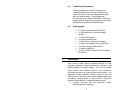 4
4
-
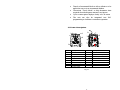 5
5
-
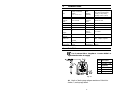 6
6
-
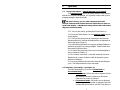 7
7
-
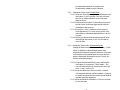 8
8
-
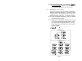 9
9
-
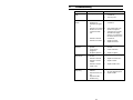 10
10
-
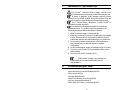 11
11
-
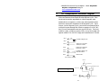 12
12
-
 13
13
-
 14
14
-
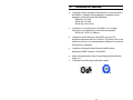 15
15
-
 16
16
-
 17
17
-
 18
18
-
 19
19
-
 20
20
-
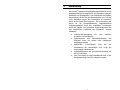 21
21
-
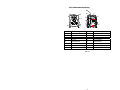 22
22
-
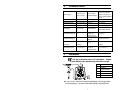 23
23
-
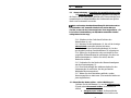 24
24
-
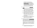 25
25
-
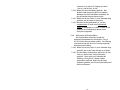 26
26
-
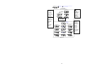 27
27
-
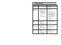 28
28
-
 29
29
-
 30
30
-
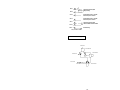 31
31
-
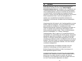 32
32
-
 33
33
-
 34
34
-
 35
35
-
 36
36
-
 37
37
-
 38
38
-
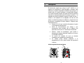 39
39
-
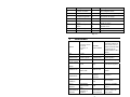 40
40
-
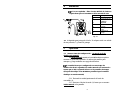 41
41
-
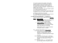 42
42
-
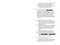 43
43
-
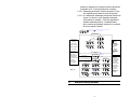 44
44
-
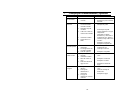 45
45
-
 46
46
-
 47
47
-
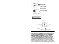 48
48
-
 49
49
-
 50
50
-
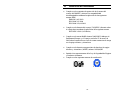 51
51
-
 52
52


Loctite 883976 Instrucciones de operación
- Tipo
- Instrucciones de operación
en otros idiomas
- English: Loctite 883976 Operating instructions
- Deutsch: Loctite 883976 Bedienungsanleitung
Otros documentos
-
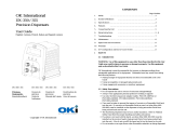 OK International DX-350 / 355 Manual de usuario
-
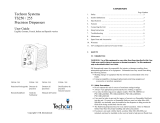 OK International TS250 Manual de usuario
-
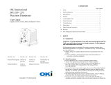 Metcal DX-250 Instrucciones de operación
-
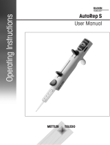 Rainin AutoRep S Instrucciones de operación
-
Chicago Pneumatic CP FL 0022 VR, CP FL0022 SVR Instrucciones de operación
-
-
Asco Series 327 High Flow Valve 1/4 1/2 Manual de usuario
-
-
-


