
FORNI POWER PIZZA
POWER PIZZA OVENS
POP434E - POP634E - POP934E
POP434ED - POP634ED - POP934ED
Manuale d’uso e manutenzione
Manuel d’utilisation et d’entretien
Use and maintenance manual
Руководство по эксплуатации и техобслуживанию
Manual de uso y mantenimiento
Bedienungs- und Wartungshandbuch

2

3
ITALIANO
INDICE
1 PREMESSA .................................................................................................................................. 5
2 AVVERTENZE PER LA SICUREZZA .......................................................................................... 5
Avvertenze per l’installatore ......................................................................................................... 5
Avvertenze per l’utilizzatore .......................................................................................................... 5
Avvertenze per il manutentore ...................................................................................................... 5
3 SPECIFICHE GENERALI ............................................................................................................. 6
Caratteristiche ................................................................................................................................ 6
Dati Tecnici ..................................................................................................................................... 6
Schemi Elettrici .............................................................................................................................. 8
4 INSTALLAZIONE ....................................................................................................................... 10
Scarico e movimentazione del forno .......................................................................................... 10
Posizionamento del forno ........................................................................................................... 10
Montaggio cappa estetica anteriore ........................................................................................... 11
Scarico dei fumi ........................................................................................................................... 11
Supporto forno e Optional supporto .......................................................................................... 11
Allacciamento agli impianti (collegamento elettrico) ............................................................... 12
Messa a terra ................................................................................................................................ 12
5 COMANDI ................................................................................................................................... 13
Descrizione del quadro comandi ................................................................................................ 13
Accensione/spegnimento del dispositivo in modo manuale.................................................................................... 14
Avvio del ciclo di cottura ............................................................................................................................................ 14
Interruzione del ciclo di cottura ................................................................................................................................. 14
I display ....................................................................................................................................................................... 14
Tacitazione del buzzer ................................................................................................................................................ 14
Luce della camera ....................................................................................................................................................... 14
Impostazione data e ora .............................................................................................................. 15
Impostazione del setpoint di lavoro ........................................................................................... 16
Impostazione della potenza erogata al cielo e di quella erogata alla platea ........................... 16
Funzione “Timer di cottura” ........................................................................................................ 17
Cenni preliminari .................................................................................................................................................... 17
Impostazione del timer di cottura ...................................................................................................................... 17
Avvio del conteggio del timer di cottura .......................................................................................................... 18
Interruzione del conteggio del timer di cottura .............................................................................................. 18
Impostazioni programmi di cottura ............................................................................................ 19
Cenni preliminari .................................................................................................................................................... 19
Memorizzazione di un programma .................................................................................................................... 19
Avvio di un programma ........................................................................................................................................ 19
Interruzione di un programma ............................................................................................................................ 19
Accensione programmata settimanale ...................................................................................... 20
Cenni preliminari .................................................................................................................................................... 20

4
Impostazione del giorno e dell’orario di accensione e del programma da avviare .............................. 20
Attivazione della funzione “accensione programmata settimanale” ....................................................... 21
Disattivazione della funzione “accensione programmata settimanale” .................................................. 22
Funzione “Energy Saving” .......................................................................................................... 22
Cenni preliminari .................................................................................................................................................... 22
Attivazione della funzione “energy saving” .................................................................................................... 22
6 MODALITÀ D’USO ..................................................................................................................... 22
Verifica funzionale ....................................................................................................................... 22
Accensione del forno .................................................................................................................. 22
Prima accensione del forno ........................................................................................................ 22
Indicazioni generali per la cottura .............................................................................................. 23
Utilizzo della valvola camino ....................................................................................................... 23
Spegnimento del forno ................................................................................................................ 23
7 MANUTENZIONE E PULIZIA ..................................................................................................... 23
Manutenzione ordinaria rivolta all’utilizzatore .......................................................................... 23
Manutenzione straordinaria rivolta a tecnici specializzati ....................................................... 24
Sostituzione delle lampade di illuminazione .................................................................................................. 24
Sostituzione delle sonda di temperatura ......................................................................................................... 24
Sostituzione del vetro porta ................................................................................................................................ 24
Sostituzione della molla porta ............................................................................................................................ 25
Sostituzione delle resistenze .............................................................................................................................. 25
Sostituzione del piano refrattario ...................................................................................................................... 25
Indicazioni per ordinare le parti di ricambio .............................................................................. 25
8 POSSIBILI ANOMALIE, ALLARMI ed ERRORI ........................................................................ 26
9 INFORMAZIONI PER LA DEMOLIZIONE E LO SMALTIMENTO ............................................. 27

5
1 PREMESSA
Gentile cliente, desideriamo innanzitutto ringraziarLa per la preferenza che ha voluto accordarci acquistando il nostro
prodotto e ci congratuliamo con Lei per la scelta.
Per consentirle di utilizzare al meglio il suo nuovo Forno, la invitiamo a seguire attentamente quanto descritto nel
presente manuale.
I forni a cui fa riferimento il presente manuale, sono stati progettati esclusivamente per soddisfare le esigenze di cottura
della pizza e di prodotti similari.
La destinazione d’uso sopra riportata e le configurazioni previste per queste apparecchiature sono le uniche ammesse
dal Costruttore: non utilizzare l’apparecchiatura in disaccordo con le indicazioni fornite.
L’installazione deve essere fatta esclusivamente da personale qualificato, in grado di garantire le migliori condizioni di
funzionamento e sicurezza.
2 AVVERTENZE PER LA SICUREZZA
Avvertenze per l’installatore
Verificare che le predisposizioni all’accoglimento del forno siano conformi ai regolamenti locali, nazionali ed europei.
• Osservare le prescrizioni indicate nel presente manuale.
• Non effettuare collegamenti elettrici volanti con cavi provvisori o non isolati.
• Verificare che la messa a terra dell’impianto elettrico sia efficiente.
• Usare sempre i dispositivi di sicurezza individuale e gli altri mezzi di protezione previsti per legge.
Avvertenze per l’utilizzatore
Le condizioni ambientali del luogo dove viene installato il forno deve avere le seguenti caratteristiche:
• Essere asciutto;
• Fonti idriche e di calore adeguatamente distanti;
• Ventilazione ed illuminazione adeguata e rispondenti alle norme igieniche e di sicurezza previste dalle leggi vigenti;
• Il pavimento deve essere piano e compatto per favorire una pulizia accurata;
• Non devono essere posti nelle immediate vicinanze del forno, ostacoli di qualunque natura che possano
condizionare la normale ventilazione dello stesso.
Inoltre l’utilizzatore deve:
• Fare attenzione che i bambini non si avvicinino con il forno in funzione;
• Osservare le prescrizioni indicate nel presente manuale;
• Non rimuovere o manomettere i dispositivi di sicurezza del forno;
• Prestare sempre la massima attenzione, ovvero osservare il proprio lavoro e non utilizzare il forno quando si è
distratti;
• Rispettare le istruzioni e gli avvertimenti evidenziati dalle targhette esposte sul forno.
Le targhette sono dispositivi antinfortunistici, pertanto devono essere sempre perfettamente leggibili. Qualora
risultassero danneggiate ed illeggibili è obbligatorio sostituirle, richiedendone il ricambio originale al Costruttore.
• Alla fine di ogni utilizzo e prima delle operazioni di pulizia e di manutenzione togliere l’alimentazione elettrica.
Avvertenze per il manutentore
Osservare le prescrizione indicate nel presente manuale:
• Usare sempre i dispositivi di sicurezza individuale e gli altri mezzi di protezione.
• Prima di iniziare qualsiasi operazione di manutenzione assicurarsi che il forno, nel caso sia stato utilizzato, si sia
raffreddato.
• Qualora anche uno dei dispositivi di sicurezza risultasse starato o non funzionante, il forno è da considerarsi non
funzionante.
• Togliere l’alimentazione elettrica prima di intervenire su parti elettriche, elettroniche e connettori.

6
3 SPECIFICHE GENERALI
Caratteristiche
Qui di seguito le specifiche generali che caratterizzano il forno POWER PIZZA:
1. Interruttore generale;
2. Frontale comandi;
3. Piano di cottura Active Stone ®;
4. Pomello valvola camino;
5. Camino uscita fumi con alette
pieghevoli anti occlusione;
6. Passacavo alimentazione;
7. Attacco equipotenziale;
8. Targhetta dati tecnici.
Dati Tecnici
Caratteristiche tecniche
Modello
POP434E
POP634E
POP934E
Dimensioni esterne
A mm
B mm
C mm
1112
1010
400
1462
1010
400
1462
1360
400
Dimensioni camera
L mm
P mm
H mm
700
700
150
1050
700
150
1050
1050
150
Nr. pizze per camera
Ø 34 cm
4
6
9
Ø 50 cm
1
2
2
Alimentazione elettrica (50/60
Hz)
Volt
230 1+N+T; 230 3+T; 400 3+N+T
Potenza massima assorbita
kW
6,6
9,35
13,67
Ampere max
230V 1+N
230V 3
400V 3+N
28,7
16,6
9,5
41
25,2
14,5
59,5
36
20,7
Cavo di alimentazione
(n x mm2)
230 1P+N
230 3P
400 3P+N
3 x 4
4 x 2,5
5 x 1,5
3 x 6
4 x 4
5 x 2,5
3 x 10
4 x 6
5 x 4
Temperatura massima di
esercizio
° C
430
Peso netto
Kg
85
139
159
Dimensioni imballo
L mm
P mm
H mm
1200
1200
540
1550
1200
540
1550
1550
540

7
Caratteristiche tecniche
Modello
POP434ED
POP634ED
POP934ED
Dimensioni esterne
A mm
B mm
C mm
1112
1010
720
1462
1010
720
1462
1360
720
Dimensioni camera
L mm
P mm
H mm
700
700
150
1050
700
150
1050
1050
150
Nr. pizze per camera
Ø 34 cm
4
6
9
Ø 50 cm
1
2
2
Alimentazione elettrica (50/60
Hz)
Volt
230 1+N+T; 230 3+T; 400 3+N+T
Potenza massima assorbita
kW
13,2
18,7
27,34
Ampere max
230V 1+N
230V 3
400V 3+N
57,4
33,2
19
-
50,4
29
-
-
41,4
Cavo di alimentazione
(n x mm2)
230 1P+N
230 3P
400 3P+N
3 x 4
4 x 2,5
5 x 1,5
3 x 6
4 x 4
5 x 2,5
3 x 10
4 x 6
5 x 4
Temperatura massima di
esercizio
° C
430
Peso netto
Kg
183
231
290
Dimensioni imballo
L mm
P mm
H mm
1200
1200
860
1550
1200
860
1550
1550
860

8
Schemi Elettrici

9

10
4 INSTALLAZIONE
Scarico e movimentazione del forno
Lo scarico e la movimentazione del forno deve essere fatta tramite un carrello elevatore da personale qualificato.
Posizionamento del forno
L’installazione del forno deve essere fatta da personale qualificato secondo i regolamenti locali, nazionali ed europei.
Assicurarsi che il piano d’appoggio del forno abbia un’adeguata capacità portante e che sia in piano.
Dopo aver estratto il forno dall’ apposito imballo, posizionarlo dove previsto tenendo conto delle distanze minime di sicurezza
dai muri e/o altre attrezzature.
Per fare in modo che il forno sia ben areato la distanza minima dai muri e/o altre attrezzature non deve essere inferiore a 10
cm sul lato sinistro e posteriore.
Mantenere una distanza di minimo 20 cm per il passaggio dell’aria sul lato destro, dove possibile almeno 50 cm per poter
accedere comodamente all’impianto elettrico in caso di manutenzione e/o riparazione.
Rimuovere eventuali protezioni in polistirolo ed asportare il film protettivo evitando di usare utensili che possono
danneggiare le superfici.

11
Montaggio cappa estetica anteriore
La cappa estetica anteriore viene fornito su ordinazione come Accessorio
e viene montato come segue.
(Le istruzioni dettagliate vengono fornite anche all’interno dell’imballo
cappa).
Scarico dei fumi
L’ evacuazione dei fumi e vapori di cottura è possibile effettuarla nelle due modalità qui sotto indicate, ovvero tramite due tubi
collegati direttamente al camino e alla cappa estetica anteriore, oppure tramite una cappa (non fornita) posizionata sopra il
forno.
Supporto forno e Optional supporto
Il supporto forno, e relativo Optional viene fornito su ordinazione come Accessorio e dev’essere montato come segue:
(Le istruzioni dettagliate vengono fornite anche all’interno dell’imballo supporto).

12
Allacciamento agli impianti (collegamento elettrico)
Il forno viene fornito privo di cavo di alimentazione. Il collegamento alla rete elettrica deve essere eseguito interponendo un
interruttore magnetotermico differenziale con caratteristiche adeguate, nel quale la distanza d’ apertura minima tra i contatti sia
di almeno 3 mm.
Per collegare il forno alla rete elettrica è indispensabile procedere come segue:
• Togliere il pannello laterale destro;
• Collegare alla morsettiera i conduttori del cavo di alimentazione, che deve essere del tipo H07-RNF omologato, con
conduttori di sezione adeguata secondo le prescrizioni delle normative vigenti.
SEGUIRE INOLTRE LE SEGUENTI DISPOSIZIONI:
• La presa della rete elettrica deve essere facilmente accessibile e non deve richiedere alcun spostamento.
• Il collegamento elettrico deve essere facilmente accessibile anche dopo l’installazione del forno.
• La distanza tra il forno e la presa deve essere tale da non provocare la tensione del cavo di alimentazione. Inoltre, il
cavo stesso non deve trovarsi sotto il basamento del forno.
• Se il cavo di alimentazione risulta danneggiato deve essere sostituito dal servizio di assistenza tecnica o da un
tecnico qualificato in modo da prevenire ogni rischio.
Messa a terra
È obbligatorio che l’impianto sia provvisto di messa a terra.
In ottemperanza alle normative vigenti è obbligatorio collegare l’apparecchiatura ad un sistema equipotenziale la cui
efficienza deve essere correttamente verificata secondo le norme in vigore.
Il collegamento si effettua sull’apposito morsetto situato nella parte posteriore del forno, con un cavo di sezione minima
10mm2.
Tale morsetto è contraddistinto dal seguente simbolo:

13
5 COMANDI
Descrizione del quadro comandi
1 Tasto “ACCENSIONE/SPEGNIMENTO”
2 Display “SUPERIORE”
3 Display “INFERIORE”
4 Tasto “CIELO”
5 Tasto “PLATEA”
6 Tasto “INCREMENTO”
7 Tasto “DECREMENTO”
8 Tasto “OROLOGIO”
9 Tasto “PROGRAMMI”
10 Tasto “START/STOP” ciclo
La seguente tabella illustra il significato dei LED del dispositivo.
Simbolo
Descrizione
Se acceso: camera in funzione;
Se lampeggia: sarà in corso l’impostazione del setpoint di lavoro.
Se acceso: visualizza la temperatura associata alla camera;
Se lampeggia: sarà in corso l’impostazione del setpoint di lavoro.
: LED energy saving
Se è acceso, sarà in corso la funzione “energy saving”
: potenza cielo
Se acceso: visualizza il valore della potenza erogata al cielo;
Se lampeggia: sarà in corso l’impostazione della potenza cielo.
: potenza platea
Se acceso: visualizza il valore della potenza erogata alla platea;
Se lampeggia: sarà in corso l’impostazione della potenza platea.
TIMER: LED timer cottura
Se acceso: conteggio del timer di cottura o in corso l’impostazione del timer
CLOCK: LED giorno e ora
Se acceso: le grandezze visualizzate nella parte bassa del display “INFERIORE”
saranno il giorno della settimana e l’orario
DELAY:
LED accensione programmata
Se acceso: in funzione “accensione programmata settimanale” o sarà in corso
l’impostazione del giorno e dell’orario di accensione e del programma da avviare
Se lampeggia: in corso la selezione dell’accensione programmata settimanale
End
Se lampeggia: il ciclo di cottura si sarà concluso

Accensione/spegnimento del dispositivo in modo manuale
Per accendere/spegnere il dispositivo in modo manuale, operare nel modo seguente:
1. Assicurarsi che non sia in corso alcuna procedura.
2. Tenere premuto il tasto “ACCENSIONE/SPEGNI-MENTO” per 1 s.
Quando viene alimentato il dispositivo ripropone lo stato in cui si trovava nell’istante in cui l’alimentazione è stata interrotta.
È inoltre possibile spegnere il dispositivo attraverso l’ingresso multifunzione; se il dispositivo è stato spento attraverso
l’attivazione dell’ingresso multifunzione, non sarà consentito accenderlo in modo manuale (fino a quando l’ingresso verrà
disattivato).
Avvio del ciclo di cottura
Per avviare il ciclo di cottura, operare nel modo seguente:
1. Assicurarsi che il timer di cottura sia impostato, che il dispositivo sia acceso e che non sia in corso alcuna procedura.
2. Premere e rilasciare il tasto “START/STOP”: il LED “TIMER” si accenderà e la parte bassa del display “SUPERIORE”
visualizzerà il conteggio residuo del timer di cottura.
Interruzione del ciclo di cottura
Per interrompere il ciclo di cottura, operare nel modo seguente:
1. Assicurarsi che non sia in corso alcuna procedura.
2. Tenere premuto il tasto “START/STOP” per 1 s: il buzzer verrà attivato per 3 s, LED “TIMER” si spegnerà e la parte
bassa del display “SUPERIORE” visualizzerà “End” lampeggiante per 3 s.
I display
La parte alta del display “SUPERIORE”
• Se il dispositivo è acceso, la parte alta del display “SUPERIORE” visualizzerà la temperatura della camera;
• Se è in corso un ciclo di cottura, la parte alta del display “SUPERIORE” visualizzerà la temperatura della camera.
• Se è stata attivata la funzione “accensione programmata settimanale”, la parte alta del display “SUPERIORE” sarà
spenta.
• Se il dispositivo è spento, la parte alta del display “SUPERIORE” sarà spenta.
La parte bassa del display “SUPERIORE”
• Se il dispositivo è acceso, la parte bassa del display “SUPERIORE” visualizzerà il valor del timer di cottura.
• Se è in corso un ciclo di cottura, la parte bassa del display “SUPERIORE” visualizzerà il conteggio residuo del timer
di cottura.
• Se è stata attivata la funzione “accensione programmata settimanale”, la parte bassa del display “SUPERIORE”
visualizzerà l’ora di accensione della prossima accensione programmata settimanale.
La parte alta del display “INFERIORE”
• Se il dispositivo è acceso, la parte alta del display “INFERIORE” visualizzerà la potenza erogata al cielo in alternanza
alla potenza erogata alla platea per 10 s;
• Se è in corso un ciclo di cottura, la parte alta del display “INFERIORE” visualizzerà la potenza erogata al cielo in
alternanza alla potenza erogata alla platea per 10 s;
• Se è stata attivata la funzione “accensione programmata settimanale”, la parte alta del display “INFERIORE” sarà
spenta.
La parte bassa del display “INFERIORE”
• Se il dispositivo è acceso, la parte bassa del display “INFERIORE” visualizzerà il valore del timer di cottura.
• Se è stata attivata la funzione “accensione programmata settimanale”, la parte bassa del display “INFERIORE” sarà
spenta.
Tacitazione del buzzer
Per tacitare il buzzer, operare nel modo seguente:
1. Assicurarsi che non sia in corso alcuna procedura.
2. Premere e rilasciare un tasto qualsiasi.
Luce della camera
Cenni preliminari
La pressione e il rilascio del tasto “DECREMENTO” (7) provocherà l’accensione della luce della camera (fino a quando il tasto
verrà premuto e rilasciato nuovamente o fino a quando il dispositivo verrà spento).
Accensione della luce della camera
Per accendere la luce della camera, operare nel modo seguente:
1. Assicurarsi che non sia in corso alcuna procedura.
2. Premere e rilasciare il tasto “DECREMENTO” (7)”: la luce della camera verrà accesa (fino a quando il tasto verrà
premuto e rilasciato nuovamente o fino a quando il dispositivo verrà spento).

15
Impostazione data e ora
Il giorno della settimana viene visualizzato nel formato 1... 7 (il numero 1 corrisponde a lunedì); l’orario viene
visualizzata nel formato 24 h (ore:minuti).
Per impostare il giorno della settimana, operare nel modo seguente:
1. Assicurarsi che non sia in corso un ciclo di cottura e che non sia in corso alcuna procedura.
2. Tenere premuto il tasto “OROLOGIO” per 1 s: il LED “CLOCK” si accenderà e la parte bassa del display
“SUPERIORE” visualizzerà il valore del giorno della settimana e quello dell’orario; il valore del giorno della
settimana lampeggerà.
3. Premere e rilasciare il tasto “INCREMENTO” o il tasto “DECREMENTO” entro 15 s per impostare il valore del
giorno.
Per impostare le ore, operare nel modo seguente:
4. Premere e rilasciare il tasto “OROLOGIO” durante l’impostazione del giorno della settimana: il valore delle ore
lampeggerà.
5. Premere e rilasciare il tasto “INCREMENTO” o il tasto “DECREMENTO” entro 15 s per impostare il valore
delle ore.
Per impostare i minuti, operare nel modo seguente:
6. Premere e rilasciare il tasto “OROLOGIO” durante l’impostazione delle ore: il valore dei minuti lampeggerà.
7. Premere e rilasciare il tasto “INCREMENTO” o il tasto “DECREMENTO” entro 15 s per impostare il valore dei
minuti.
Per uscire dalla procedura, operare nel modo seguente:
8. Premere e rilasciare il tasto “OROLOGIO” durante l’impostazione dei minuti: il LED “CLOCK” si spegnerà e il
dispositivo uscirà dalla procedura.
Per uscire anzitempo dalla procedura, operare nel modo seguente:
9. Non operare per 15 s (eventuali modifiche saranno salvate).

16
Impostazione del setpoint di lavoro
Per impostare il setpoint di lavoro, operare nel modo seguente:
1. Assicurarsi che il dispositivo non sia spento e che non
sia in corso alcuna procedura.
2. Premere e rilasciare il tasto “CIELO” o il tasto “PLATEA”:
il LED e il LED del display “SUPERIORE”
lampeggeranno e la parte alta del display visualizzerà il
valore lampeggiante del setpoint.
3. Premere e rilasciare il tasto “INCREMENTO” o il tasto
“DECREMENTO” entro 15 s per impostare il valore del
setpoint;
4. Premere e rilasciare due volte il tasto “CIELO” o il tasto
“PLATEA” o non operare per 15 s: il LED e il LED
si spegneranno e il dispositivo uscirà dalla
procedura.
Per uscire anzitempo dalla procedura, operare nel modo
seguente:
5. Non operare per 15 s (eventuali modifiche saranno
salvate).
Impostazione della potenza erogata al cielo e di quella erogata alla platea
Per impostare la potenza erogata al cielo, operare nel modo
seguente:
1. Assicurarsi che il dispositivo non sia spento e che non
sia in corso alcuna procedura.
2. Premere e rilasciare due volte il tasto “CIELO”: il LED
del display “INFERIORE” lampeggerà e la parte alta
del display visualizzerà il valore lampeggiante della
potenza.
3. Premere e rilasciare il tasto “INCREMENTO” o il tasto
“DECREMENTO” entro 15 s per impostare il valore della
potenza; si vedano anche i parametri c0 e c1.
4. Premere e rilasciare il tasto “CIELO” o non operare per
15 s: il LED si spegnerà e il dispositivo uscirà dalla
procedura.
Per uscire anzitempo dalla procedura, operare nel modo
seguente:
5. Non operare per 15 s (eventuali modifiche saranno
salvate).

17
Per impostare la potenza erogata alla platea, operare nel modo
seguente:
6. Assicurarsi che il dispositivo non sia spento e che non
sia in corso alcuna procedura.
7. Premere e rilasciare due volte il tasto “PLATEA”: il LED
del display “INFERIORE” lampeggerà e la parte
alta del display visualizzerà il valore lampeggiante della
potenza.
8. Premere e rilasciare il tasto “INCREMENTO” o il tasto
“DECREMENTO” entro 15 s per impostare il valore della
potenza; si vedano anche i parametri c0 e c1.
9. Premere e rilasciare il tasto “PLATEA” o non operare
per 15 s: il LED si spegnerà e il dispositivo uscirà
dalla procedura.
Per uscire anzitempo dalla procedura, operare nel modo
seguente:
10. Non operare per 15 s (eventuali modifiche saranno
salvate).
Funzione “Timer di cottura”
Cenni preliminari
La funzione “timer di cottura” consente di avviare il conteggio
residuo di un tempo.
L’avvio del conteggio del timer di cottura provoca l’avvio del
ciclo di cottura; l’interruzione del conteggio del timer di cottura
provoca l’interruzione del ciclo di cottura.
Il conteggio viene visualizzato nella parte bassa del display
“SUPERIORE”; durante il conteggio il LED “TIMER” è acceso.
Alla conclusione del conteggio del timer di cottura il buzzer
viene attivato e la parte bassa del display “SUPERIORE”
visualizza “End” lampeggiante.
Impostazione del timer di cottura
Il timer di cottura viene visualizzato nel formato “ore:minuti”.
Per impostare le ore, operare nel modo seguente:
1. Assicurarsi che il dispositivo non sia spento e che non
sia in corso alcuna procedura.
2. Premere e rilasciare il tasto “OROLOGIO”: il LED
“TIMER” si accenderà e la parte bassa del display
“SUPERIORE” visualizzerà il valore del timer di cottura;
il valore delle ore lampeggerà.
3. Premere e rilasciare il tasto “INCREMENTO” o il tasto
“DECREMENTO” entro 15 s per impostare il valore delle
ore.
Per impostare i minuti, operare nel modo seguente:
4. Premere e rilasciare il tasto “OROLOGIO” durante
l’impostazione delle ore: il valore dei minuti lampeggerà.
5. Premere e rilasciare il tasto “INCREMENTO” o il tasto “DECREMENTO”
ento 15 s per impostare il valore dei minuti.

18
Per uscire dalla procedura, operare nel modo seguente:
6. Premere e rilasciare il tasto “OROLOGIO” durante l’impostazione dei minuti: il LED “TIMER” si spegnerà e il
dispositivo uscirà dalla procedura.
Per uscire anzitempo dalla procedura, operare nel modo seguente:
7. Non operare per 15 s (eventuali modifiche saranno salvate).
Se il timer di cottura viene impostato durante il conteggio, tale modifica non verrà salvata.
Avvio del conteggio del timer di cottura
Per avviare il conteggio del timer di cottura, operare nel
modo seguente:
1. Assicurarsi che il dispositivo sia acceso e che non
sia in corso alcuna procedura.
2. Premere e rilasciare il tasto “START/STOP”: il
LED “TIMER” si accenderà e la parte bassa del
display “SUPERIORE” visualizzerà il conteggio
residuo del timer di cottura.
Interruzione del conteggio del timer di cottura
Per interrompere il conteggio del timer di cottura, operare
nel modo seguente:
1. Assicurarsi che non sia in corso alcuna procedura.
2. Tenere premuto il tasto “START/STOP” per 1 s: il
buzzer verrà attivato per 3 s, LED “TIMER” si
spegnerà e la parte bassa del display
“SUPERIORE” visualizzerà “End” lampeggiante
per 3 s.
Avvio del conteggio del timer di cottura

19
Impostazioni programmi di cottura
Cenni preliminari
La funzione “programmi” consente di memorizzare alcune impostazioni in un programma; all’avvio del programma il
dispositivo funzionerà con le impostazioni in esso memorizzate.
L’avvio del programma provoca l’avvio del ciclo di cottura; l’interruzione del programma provoca l’interruzione del ciclo
di cottura.
Memorizzazione di un programma
Per memorizzare un programma, operare nel modo seguente:
1. Assicurarsi che il dispositivo sia acceso, che non sia in
corso un ciclo di cottura e che non sia in corso alcuna
procedura;
2. Impostare il setpoint di lavoro, la potenza erogata al
cielo e quella erogata alla platea con le procedure
illustrate nel capitolo Impostazione del setpoint di
lavoro e Impostazione della potenza erogata al cielo
e di quella erogata alla platea;
3. Impostare il timer di cottura con la procedura illustrata
nel paragrafo “Funzione Timer di cotturaErrore. L
'origine riferimento non è stata trovata.”.
4. Tenere premuto il tasto “PROGRAMMI” per 1 s: la parte
bassa del display “INFERIORE” visualizzerà il numero
del primo programma non utilizzato; il numero del
programma lampeggerà.
5. Premere e rilasciare il tasto “INCREMENTO” o il tasto
“DECREMENTO” entro 15 s per impostare il numero del
programma.
6. Tenere premuto il tasto “PROGRAMMI” per 1 s: il
dispositivo uscirà dalla procedura.
Per uscire anzitempo dalla procedura, operare nel modo
seguente:
7. Non operare per 15 s (eventuali modifiche non saranno
salvate).
Avvio di un programma
Per avviare un programma, operare nel modo seguente:
1. Assicurarsi che il dispositivo sia acceso, che non sia in corso un ciclo di cottura e che non sia in corso alcuna
procedura.
2. Premere e rilasciare il tasto “PROGRAMMI”: la parte bassa del display “INFERIORE” visualizzerà il numero
del primo programma utilizzato e i rimanenti display del dispositivo visualizzeranno le impostazioni
memorizzate nel programma; il numero del programma lampeggerà.
Se non è utilizzato alcun programma, la parte bassa del display “INFERIORE” visualizzerà “-“ lampeggiante e
i display del dispositivo si spegneranno.
3. Premere e rilasciare il tasto “INCREMENTO” o il tasto “DECREMENTO” entro 15 s per selezionare il numero
di un programma.
4. Premere e rilasciare il tasto “START/STOP” entro 15 s: il numero del programma rimarrà stabilmente acceso
e il programma verrà avviato.
Per uscire anzitempo dalla procedura, operare nel modo seguente:
5. Premere e rilasciare il tasto “PROGRAMMI” o non operare per 15 s (il programma non verrà avviato).
Interruzione di un programma
Per interrompere un programma, operare nel modo seguente:
1. Tenere premuto il tasto “START/STOP” per 1 s: il buzzer verrà attivato per 3 s, LED “TIMER” si spegnerà e la
parte bassa del display “SUPERIORE” visualizzerà “End” lampeggiante per 3 s.

20
Accensione programmata settimanale
Cenni preliminari
La funzione “accensione programmata settimanale” consente di programmare l’accensione del dispositivo e di avviare
contemporaneamente un programma; si veda il capitolo “Impostazione programmi di cottura”.
La funzione deve essere attivata con la procedura illustrata nel paragrafo “Attivazione della funzione accensione
programmata settimanale”.
L’avvio del ciclo di cottura deve essere provocato attraverso la pressione e il rilascio del tasto “START/STOP”.
Se il parametro r12 è impostato a 0, la funzione “accensione programmata settimanale” non sarà disponibile.
Impostazione del giorno e dell’orario di accensione e del programma da avviare
Il giorno di accensione viene visualizzato nel formato 1... 7
(il numero 1 corrisponde a lunedì); l’orario viene visualizzata nel formato 24 h (ore:minuti).
Per impostare il giorno di accensione, operare nel modo seguente:
1. Assicurarsi che il parametro r12 sia impostato a 1,
che siano utilizzati dei programmi, che il dispositivo
sia spento e che non sia in corso alcuna procedura.
2. Tenere premuto il tasto “PROGRAMMI” per 1 s: il
LED “DELAY” si accenderà e la parte bassa del
display “SUPERIORE” visualizzerà il valore del
giorno di accensione; il valore del giorno
lampeggerà.
Se non è impostata alcuna ora di accensione, la
parte bassa del display “SUPERIORE” visualizzerà
solo il valore del giorno di accensione.
3. Premere e rilasciare il tasto “INCREMENTO” o il
tasto “DECREMENTO” entro 15 s per impostare il
valore del giorno.
Per impostare il programma da avviare, operare nel modo
seguente:
4. Premere e rilasciare il tasto “PROGRAMMI” durante
l’impostazione del giorno di accensione: la parte
bassa del display “INFERIORE” visualizzerà il
numero del primo programma utilizzato; il numero
del programma lampeggerà.
Se non è utilizzato alcun programma, la parte bassa del display
“INFERIORE” visualizzerà “-“ lampeggiante.
5. Premere e rilasciare il tasto “INCREMENTO” o il
tasto “DECREMENTO” entro 15 s per selezionare il
numero di un programma.
Per impostare l’orario di accensione, operare nel modo seguente:
6. Per impostare le ore, premere e rilasciare il tasto “PROGRAMMI” durante l’impostazione del programma
da avviare: il valore delle ore lampeggerà.
7. Premere e rilasciare il tasto “INCREMENTO” o il tasto “DECREMENTO” entro 15 s per impostare il valore
delle ore.
8. Per impostare i minuti, premere e rilasciare il tasto “PROGRAMMI” durante l’impostazione delle ore: il
valore dei minuti lampeggerà.
9. Premere e rilasciare il tasto “INCREMENTO” o il tasto “DECREMENTO” entro 15 s per impostare il valore
dei minuti.

21
Per impostare un altro giorno di accensione, operare nel modo
seguente:
10. Premere e rilasciare il tasto “PROGRAMMI”
durante l’impostazione dei minuti: il valore del
giorno lampeggerà.
11. Ripetere i punti 3... 9.
Per uscire dalla procedura, operare nel modo
seguente:
12. Tenere premuto il tasto “PROGRAMMI” per 1 s: il
LED “DELAY” si spegnerà.
Per uscire anzitempo dalla procedura, operare nel
modo seguente:
13. Non operare per 60 s (eventuali modifiche non
saranno salvate).
Attivazione della funzione “accensione programmata
settimanale”
Per attivare la funzione “accensione programmata
settimanale”, operare nel modo seguente:
1. Assicurarsi che siano impostati dei giorni e degli
orari di accensione e dei programmi da avviare.
2. Spegnere il dispositivo attraverso la pressione del
tasto “ACCENSIONE/SPEGNIMENTO” per 1 s: il
LED “DELAY” lampeggerà, la parte bassa del
display “SUPERIORE” visualizzerà il giorno e l’ora
di accensione della prossima accensione
programmata settimanale e la parte bassa del
display “INFERIORE” visualizzerà il numero del
programma da avviare.
3. Premere e rilasciare il tasto “INCREMENTO” o il
tasto “DECREMENTO” entro 15 s per selezionare
un’accensione programmata settimanale.
4. Tenere premuto il tasto “START/STOP” per 1 s
entro 15 s: il LED “DELAY” rimarrà stabilmente
acceso, i display del dispositivo visualizzeranno il
giorno e l’ora di accensione della prossima
accensione programmata e il numero del
programma da avviare e il dispositivo uscirà dalla
procedura.
Se un’accensione programmata settimanale viene modificata
attraverso la pressione e il rilascio del tasto “PROGRAMMI”, del tasto “INCREMENTO” e del tasto “DECREMENTO”
dopo che la funzione è stata attivata, tale modifica non verrà salvata.

22
Per uscire anzitempo dalla procedura, operare nel modo seguente:
5. Premere e rilasciare il tasto ” ACCENSIONE/SPEGNIMENTO” o non operare per 15 s (eventuali
modifiche non saranno salvate).
Disattivazione della funzione “accensione programmata settimanale”
Per disattivare la funzione “accensione programmata settimanale”, operare nel modo seguente:
1. Assicurarsi che non sia in corso alcuna procedura.
2. Tenere premuto il tasto “START/STOP” per 1 s: il LED “DELAY” si spegnerà.
Funzione “Energy Saving”
Cenni preliminari
La funzione “energy saving” consente di ridurre l’assorbimento elettrico dell’uscita cielo e dell’uscita platea,
accendendo l’una quando l’altra è spenta.
La modalità di attuazione della funzione “energy saving” provocherà un adattamento automatico della potenza erogata
alla platea tale da garantire che la somma del valore della potenza erogata al cielo con quello della potenza erogata
alla platea sia 100 (es.: cielo 70 + platea 30 = 100).
Attivazione della funzione “energy saving”
Per attivare la funzione “energy saving”, operare nel modo seguente:
1. Assicurarsi che il dispositivo non sia spento, che non sia in corso alcuna procedura e che non sia in corso
la funzione “riscaldamento rapido”
2. Premere e rilasciare il tasto “INCREMENTO”: il LED si accenderà e la funzione verrà attivata (fino a
quando il tasto verrà premuto e rilasciato nuovamente o al massimo di tempo di 2 ore)
Se il dispositivo viene spento quando la funzione “energy saving” è in corso, alla successiva accensione la funzione
non verrà riproposta; se si manifesta un’interruzione dell’alimentazione quando la funzione è in corso, al ripristino
dell’alimentazione la funzione verrà riproposta per la durata di 2 ore, se non spenta manualmente tramite il tasto
“INCREMEMNTO”.
6 MODALITÀ D’USO
Verifica funzionale
Prima di accendere il forno verificare:
• Di aver asportato il film protettivo dove presente;
• Di aver inserito correttamente la spina nella presa d’alimentazione elettrica;
• Che la tensione d’alimentazione, la frequenza e la potenza dell’impianto siano compatibili con i valori riportati
nella targhetta apposta sul lato destro del forno;
Accensione del forno
Per accendere il forno POWER PIZZA procedere nel modo seguente:
• Ruotare l’interruttore generale in posizione 1;
• Premere il tasto “ACCENSINE/SPEGNIMENTO” per accendere il display;
• Impostare la temperatura desiderata sul Termostato (display SUPERIORE);
• Impostare la percentuale di potenza del Cielo e della Platea (display INFERIORE);
• Impostare il timer di cottura (ciclo di cottura);
Prima accensione del forno
Al primo utilizzo dell’apparecchiatura è consigliabile riscaldare il forno a vuoto per eliminare cattivi odori causati dall’
evaporazione dell’umidità contenuta nelle pietre refrattarie, nel materiale isolante e nelle parti metalliche interne.
Seguire la seguente procedura:
• Chiudere tutte le porte e aprire al massimo le valvole camino;

23
• Impostare la temperatura a 150° C;
• Impostare la percentuale di cielo e platea a 100%;
• Impostare il timer di cottura a 8:00 ore.
Indicazioni generali per la cottura
La pizza ed i prodotti similari, hanno tempi e temperature di cottura che dipendono dalla forma e dallo spessore della pasta,
nonché dalla quantità e tipologia degli ingredienti aggiunti.
Per tali motivi è sempre consigliabile effettuare preventivamente alcune prove di cottura, al fine di comprenderne al meglio
le caratteristiche ed il funzionamento del forno.
Indicativamente le impostazioni del forno sono le seguenti:
• Tenere la valvola del camino chiusa fin tanto che il forno non ha raggiunto la temperatura impostata;
• È preferibile cucinare direttamente sulle pietre, in modo da ottenere un risultato migliore del prodotto;
• Impostare la potenza del Cielo tra il 60 e l’80%, mai sotto il 30%;
• Impostare la potenza della Platea tra 0 e 30%, se si cucina direttamente sulle pietre.
Se si fanno più infornate di seguito, aumentare il Cielo al 90÷100% e la Platea al 50% della potenza.
• Se si cucina con la teglia impostare il Cielo tra il 30 e il 50%, la Platea tra il 60 e l’80%.
Utilizzo della valvola camino
La valvola del camino consente la regolazione del deflusso di fumi e vapori dalla camera di cottura ed il mantenimento in
essa del calore.
Si consiglia di mantenere la valvola totalmente chiusa quando il forno è in fase di riscaldamento, per raggiungere nel minor
tempo possibile la temperatura desiderata. Durante la cottura regolare la valvola a seconda delle proprie esigenze.
Spegnimento del forno
Per spegnere il forno seguire la seguente procedura:
• Tenere premuto il tasto “ACCENSIONE/SPEGNIMENTO” per 1 s;
• Portare l’interruttore generale in posizione 0.
7 MANUTENZIONE E PULIZIA
Precauzioni di sicurezza
Prima di effettuare qualsiasi operazione di manutenzione, adottare le seguenti precauzioni di sicurezza:
• Accertarsi che il forno sia spento e completamente raffreddato;
• Accertarsi che il forno non sia alimentato elettricamente;
• Accertarsi che l’alimentazione non possa essere riattivata accidentalmente; staccare la spina dalla presa di
alimentazione elettrica;
• Utilizzare i dispositivi di protezione individuale previsti dalla direttiva 89/391/CEE;
• Non utilizzare agenti chimici sulle pietre refrattarie e le parti interne del forno;
• Non utilizzare acqua tramite tubi o dispositivi di lavaggio ad alta pressione;
• Non utilizzare materiali o spugne abrasive per pulire i vetri porta e le parti metalliche del forno;
• Non pulire il vetro porta quando è caldo;
• Installare tutte le protezione e riattivare tutti i dispositivi di sicurezza una volta terminata la manutenzione o le
operazioni di riparazione, prima di rimettere il forno in servizio.
Manutenzione ordinaria rivolta all’utilizzatore
Prima di eseguire qualsiasi intervento di manutenzione interrompere l’alimentazione elettrica e seguire le “Precauzioni di
sicurezza”.
Per mantenere il forno sempre pulito ed efficiente è necessaria una pulizia e manutenzione ordinaria da effettuare
ad intervalli regolari come segue:

24
• Pulizia giornaliera
1. Pulire la parte interna della camera di cottura utilizzando uno spazzola di metallo per togliere depositi di
farina e residui della cottura;
2. Pulire internamente ed esternamente il vetro della porta con un panno morbido e un detergente delicato;
Non utilizzare spugne abrasive.
3. Pulire le parti esterne del forno come porte, maniglie della porta e frontale comandi con un panno morbido
e un detergente delicato.
Non utilizzare spugne abrasive.
• Pulizia settimanale
Pulire accuratamente tutte le parti esterne del forno con un panno morbido e un detergente delicato.
Non utilizzare spugne abrasive.
• Pulizia mensile
Lubrificare i perni e la molla porta con un grasso spray non tossico.
Per accedere alla molla aprire il pannello laterale sinistro.
• Pulizia annuale
1. Tramite un aspirapolvere pulire l’interno della camera di cottura;
2. Pulire tutte le uscite di ventilazione poste sulla parte frontale, laterale e posteriore del forno;
3. Togliere il pannello laterale destro e, tramite un aspirapolvere, aspirare completamente l’interno del vano
comandi, facendo attenzione a non rovinare i componenti ed i cablaggi elettrici.
Manutenzione straordinaria rivolta a tecnici specializzati
Per qualsiasi operazione che non sia di competenza dell’utilizzatore, è necessario richiedere l’intervento di un tecnico
specializzato.
Rivolgersi quindi al proprio rivenditore e/o servizio di assistenza di zona.
Prima di eseguire qualsiasi intervento di manutenzione interrompere l’alimentazione elettrica e seguire le “Precauzioni di
sicurezza”.
Sostituzione delle lampade di illuminazione
Una volta eseguite le “Precauzioni di sicurezza” fare attenzione a:
• Non sostituire mai la lampada con il forno caldo;
• Aspettare che il forno si raffreddi.
• Non toccare la lampada con le mani, utilizzare sempre dei guanti, un pezzo di carta o un panno, in modo da evitare
di rovinarla e di conseguenza diminuire la durata di vita della lampada;
Sostituire la lampada come segue:
• Svitare la calotta di protezione della lampada posta sul lato interno della camera di cottura;
• Estrarre e sostituire la lampada d’illuminazione;
• Riavvitare la calotta di protezione.
Sostituzione delle sonda di temperatura
Una volta eseguite le “Precauzioni di sicurezza” sostituire la sonda come segue:
• Togliere il pannello laterale destro;
• Scollegare la sonda dalla scheda di potenza all’interno del vano impianto elettrico;
• Svitare la vite di fissaggio della sonda posta all’interno della camera;
• Sfilare la sonda dall’interno camera;
• Sostituire la sonda infilandola dall’interno camera;
• Eseguire le operazioni inverse per il rimontaggio, facendo attenzione di collegare correttamente le polarità della
sonda (vedi schema elettrico).
Sostituzione del vetro porta
Una volta eseguite le “Precauzioni di sicurezza” sostituire il vetro porta come segue:
• Svitare le viti di fissaggio della controporta e rimuoverla, facendo attenzione a non far cadere il vetro;
• Sostituire il vetro e verificare se è necessario sostituire la guarnizione porta;
• Eseguire le operazioni inverse di per il montaggio.

25
Sostituzione della molla porta
Una volta eseguite le “Precauzioni di sicurezza” sostituire la molla porta come segue:
• Togliere il pannello laterale sinistro;
• Svitare il dado sulla vite della molla per sganciarla;
• Sostituire la molla agganciandola alla rotella di rotazione, regolare la tensione della molla tramite il dado di blocco
sulla vite;
• Rimontare il pannello laterale.
Sostituzione delle resistenze
Una volta eseguite le “Precauzioni di sicurezza” sostituire le resistenze porta come segue:
• Per sostituire le resistenze del cielo togliere il pannello laterale destro;
• Scollegare i fili di alimentazione relativi alle resistenze da sostituire;
• Spostare la lana di roccia per accedere alle viti di fissaggio delle resistenze da sostituire;
• Togliere le resistenze;
• Eseguire le operazioni inverse per il rimontaggio.
• Per sostituire le resistenze della platea togliere il pannello posteriore;
• Scollegare i fili di alimentazione relativi alle resistenze da sostituire;
• Spostare la lana di roccia per accedere alle viti di fissaggio delle resistenze da sostituire;
• Togliere le resistenze;
• Eseguire le operazioni inverse per il rimontaggio.
Sostituzione del piano refrattario
ATTENZIONE!
Per eseguire questa operazione è consigliabile togliere le resistenze della platea inserite all’interno dei singoli
piani refrattari (vedi Sostituzione delle resistenze della platea).
Una volta eseguite le “Precauzioni di sicurezza” sostituire il piano refrattario come segue:
• Togliere le resistenze relative al piano refrattario da sostituire (vedi Sostituzione delle resistenze);
• Aprire la porta della camera;
• Sollevare il piano refrattario facendo leva con un cacciavite;
• Sostituire il piano refrattario;
• Eseguire le operazioni di rimontaggio delle resistenze.
Indicazioni per ordinare le parti di ricambio
Per ordinare le parti di ricambio devono essere comunicati i seguenti dati, che si trovano nella targhetta argentata
posizionata sul lato destro del forno:
• Modello del forno;
• Matricola del forno (Numero di Serie);
• Codice del componente (vedi lista ricambi);
• Quantità occorrente.

26
8 POSSIBILI ANOMALIE, ALLARMI ed ERRORI
Anomalia
Possibile Causa
Possibile Soluzione
Il forno non si accende, i display
rimangono spenti
Mancanza di energia elettrica
Verificare l’interruttore generale, la presa,
la spina ed il cavo di alimentazione, la
morsettiera interna al vano comandi
L’interruttore generale è in posizione
“0”
Portare l’interruttore generale in posizione
“1”
L’interruttore generale del forno è
guasto
Sostituire l’interruttore generale del forno
L’interruttore di sicurezza all’interno
dell’impianto è in posizione “0”
Portare l’interruttore di sicurezza in
posizione “1”
Intervento del Termostato di
sicurezza
Aprire il pannello destro, rispristinare il
termostato e l’interruttore di sicurezza
Il display è spento nonostante
l’interruttore generale sia in
posizione “1” e l'alimentazione
elettrica sia presente
Dispositivo/i spento/i
Premere il tasto
ACCENSIONE/SPEGNIMENTO per 1
secondo
Dispositivo guasto
Sostituire il dispositivo
Una o più lampade non si
accendono anche se il forno
riscalda
Una o più lampade sono bruciate
Sostituire le lampade bruciate
Il trasformatore è guasto
Sostituire il trasformatore
Il portalampada è guasto
Sostituire il portalampada
La camera di cottura non si
riscalda adeguatamente
Cielo e/o platea sono stati impostati
troppo bassi
Aumentare la percentuale di cielo e/o
platea
Le resistenze sono parzialmente
funzionanti
Verificare la tensione sulle resistenze
Verificare se le resistenze sono guaste
La scheda relè è guasta
Sostituire la scheda relè
La valvola camino è troppo aperta
Regolare la valvola camino
La temperatura continua a salire
oltre le impostazioni effettuate
mediante il termostato
Contatti della scheda relè incollati
(resistenze sempre alimentate)
Verificare ed eventualmente sostituire la
scheda relè
La valvola camino è chiusa
Regolare la valvola camino
La porta è chiusa ma fuoriesce
fumo
Valvola camino chiusa
Aprire maggiormente la valvola e
verificarne il corretto funzionamento.
Allarme
Causa
Soluzione
Ht
Alta temperatura vano comandi
Verificare eventuali ostruzioni
all’areazione del vano impianto elettrico
PF
Allarme interruzione
dell’alimentazione
Premere e rilasciare un tasto
PF1
Allarme interruzione
dell’alimentazione durante il
conteggio del timer di cottura di
durata tale da non provocare
l’interruzione del ciclo di cottura
Verificare il collegamento dispositivo
alimentazione
Premere e rilasciare un tasto
PF2
Allarme interruzione
dell’alimentazione durante il
conteggio del timer di cottura di
durata tale da provocare
l’interruzione del ciclo di cottura
Verificare il collegamento dispositivo
alimentazione
Premere e rilasciare un tasto

27
Errore
Causa
Soluzione
Pr1: Errore sonda camera
Sonda guasta
Sostituzione sonda
Sonda scollegata dal dispositivo
Collegare correttamente la sonda
EOC: errore giunto freddo
Sonda guasta della scheda di
controllo
Sostituire la scheda di controllo
Rtc: errore orologio
“Accensione settimanale” non
disponibile
Impostare Date e Ora
9 INFORMAZIONI PER LA DEMOLIZIONE E LO SMALTIMENTO
Ai sensi dell’art. 13 del Decreto Legislativo 25 luglio 2005 n.151 “Attuazione delle Direttive 2002/95/CE,
2002/96/CE, 2003/108/CE, relative alla riduzione dell’uso di sostanze pericolose nelle apparecchiature
elettriche ed elettroniche, nonché allo smaltimento dei rifiuti”.
Il simbolo del cassonetto barrato riportato sull’apparecchiatura o sulla sua confezione indica che il prodotto alla fine della propria
vita utile deve essere raccolto separatamente dagli altri rifiuti.
La raccolta della presente apparecchiatura giunta a fine vita è organizzata e gestita dal produttore. L’utente che vorrà disfarsi
della presente apparecchiatura dovrà quindi contattare il produttore e seguire il sistema che questo ha adottato per consentire
la raccolta separata dell’apparecchiatura giunta a fine vita.
L’adeguata raccolta differenziata per l’avvio successivo dell’apparecchiatura dismessa al riciclaggio, al trattamento e allo
smaltimento ambientale compatibile contribuisce ad evitare possibili effetti negativi sull’ambiente e sulla salute e favorisce il
reimpiego e/o riciclo dei materiali di cui è composta l’apparecchiatura. Lo smaltimento abusivo del prodotto da parte del
detentore comporta l’applicazione delle sanzioni amministrative previste dalla norma vigente.
Iscr. Reg. Nazionale dei Produttori di AEE con il numero:
IT08020000000645

28
FRANÇAIS
TABLE DES MATIÈRES
1 AVANT-PROPOS ....................................................................................................................... 30
2 MISES EN GARDE POUR LA SÉCURITÉ ................................................................................. 30
Consignes pour l’installateur ...................................................................................................... 30
Consignes pour l’utilisateur ........................................................................................................ 30
Consignes pour le technicien de maintenance ......................................................................... 30
3 SPÉCIFICATIONS GÉNÉRALES ............................................................................................... 31
Caractéristiques ........................................................................................................................... 31
Données techniques .................................................................................................................... 31
Schémas électriques ................................................................................................................... 33
4 INSTALLATION .......................................................................................................................... 35
Déchargement et manutention du four ...................................................................................... 35
Positionnement du four ............................................................................................................... 35
Montage hotte esthétique avant ................................................................................................. 36
Évacuation des fumées ............................................................................................................... 36
Support du four et support en option ........................................................................................ 36
Raccordement aux installations (connexion électrique) .......................................................... 37
Mise à la terre ............................................................................................................................... 37
5 COMMANDES ............................................................................................................................ 38
Description du tableau de commande ....................................................................................... 38
Allumage/extinction du dispositif en mode manuel ................................................................................................ 39
Activation du cycle de cuisson ................................................................................................................................... 39
Interruption du cycle de cuisson ................................................................................................................................ 39
Les afficheurs .............................................................................................................................................................. 39
Mise sous silence de l'avertisseur sonore ................................................................................................................. 39
Lumière de la chambre ............................................................................................................................................... 39
Réglage date et heure .................................................................................................................. 40
Réglage du point de consigne de travail ................................................................................... 41
Réglage de la puissance distribuée au ciel et celle au sol ....................................................... 41
Fonction “Temporisateur de cuisson” ....................................................................................... 42
Gestes préliminaires ............................................................................................................................................. 42
Réglage du temporisateur de cuisson ............................................................................................................. 42
Activation du comptage du temporisateur de cuisson ................................................................................ 43
Interruption du comptage du temporisateur de cuisson ............................................................................. 43
Réglages programmes de cuisson ............................................................................................. 44
Gestes préliminaires ............................................................................................................................................. 44
Mémorisation d'un programme .......................................................................................................................... 44
Activation d'un programme ................................................................................................................................. 44
Interruption d'un programme .............................................................................................................................. 44
Allumage programmé hebdomadaire ......................................................................................... 45
Gestes préliminaires ............................................................................................................................................. 45

29
Réglage du jour et de l' horaire d'allumage et du programme à activer ................................................. 45
Activation de la fonction “allumage programmé hebdomadaire” ............................................................ 46
Désactivation de la fonction “allumage programmé hebdomadaire” ...................................................... 47
Fonction “Energy Saving” (Économie d'énergie) ..................................................................... 47
Gestes préliminaires ............................................................................................................................................. 47
Activation de la fonction “energy saving” ...................................................................................................... 47
6 MODE D'EMPLOI ....................................................................................................................... 47
Vérification fonctionnelle ............................................................................................................ 47
Allumage du four ......................................................................................................................... 47
Premier allumage du four ............................................................................................................ 47
Indications générales pour la cuisson ....................................................................................... 48
Utilisation de la vanne de la cheminée....................................................................................... 48
Extinction du four ........................................................................................................................ 48
7 ENTRETIEN ET NETTOYAGE ................................................................................................... 48
Entretien ordinaire incombant à l'utilisateur ............................................................................. 48
Maintenance extraordinaire destinée à des techniciens spécialisés ...................................... 49
Remplacement des lampes d'éclairage............................................................................................................ 49
Remplacement de la sonde de température ................................................................................................... 49
Remplacement de la vitre de la porte ............................................................................................................... 49
Remplacement du ressort de la porte .............................................................................................................. 50
Remplacement des résistances ......................................................................................................................... 50
Remplacement du plan réfractaire .................................................................................................................... 50
Indications pour commander les pièces de rechange .............................................................. 50
8 ANOMALIES POSSIBLES, ALARMES et ERREURS ............................................................... 51
9 INFORMATIONS POUR LA DÉMOLITION ET LA MISE AU REBUT ....................................... 52

30
1 AVANT-PROPOS
Cher client, nous souhaitons tout d’abord vous remercier de la préférence que vous avez bien voulu nous accorder en
achetant notre produit et souhaitons vous féliciter pour votre choix.
Pour vous permettre de tirer le meilleur parti de votre nouveau four, veuillez suivre attentivement les instructions de ce
manuel.
Les fours mentionnés dans ce manuel ont été conçus exclusivement pour répondre aux besoins de cuisson des pizzas
et produits similaires.
La destination d’usage reportée ci-dessus et les réglages prévus pour ces équipements sont les seuls admis par le
Fabricant : ne pas utiliser l'équipement en désaccord avec les indications fournies.
L’installation doit être faite exclusivement par du personnel qualifié, en mesure de garantir les meilleurs conditions de
fonctionnement et sécurité.
2 MISES EN GARDE POUR LA SÉCURITÉ
Consignes pour l’installateur
Vérifier que les prédispositions pour l'installation du four sont conformes aux réglementations locales, nationales et
européennes.
• Observer les prescriptions indiquées dans ce manuel.
• Ne pas effectuer de connexions électriques aériennes avec des câbles provisoires ou non isolés.
• Vérifier que la mise à la terre de l’installation électrique soit efficace.
• Toujours utiliser les équipements de protection individuelle et les autres moyens de protection prévus par la loi.
Consignes pour l’utilisateur
Les conditions ambiantes du lieu où le four est installé doivent avoir les caractéristiques suivantes :
• Être sec ;
• Sources hydriques et de chaleur suffisamment éloignées ;
• Ventilation et éclairage approprié et répondant aux normes hygiéniques et de sécurité prévues par les lois en
vigueur ;
• Le sol dot être plat et compact pour favoriser un nettoyage soigné ;
• Aucun obstacle de quelque sorte que ce soit ne doit être placé à proximité immédiate du four, ce qui pourrait affecter
la ventilation normale de celui-ci.
L’utilisateur doit en outre :
• Veiller à ce que les enfants ne s'approchent pas du four quand il fonctionne ;
• Observer les prescriptions indiquées dans ce manuel ;
• Ne pas enlever ou altérer les dispositifs de sécurité du four ;
• Faire toujours très attention, à savoir être concentré sur son travail et ne pas utiliser le four lorsqu'on est distrait ;
• Respecter les instructions et les avertissements mis en évidence par les plaques exposées sur le four.
Les plaques sont des dispositifs pour la prévention des accidents, par conséquent elles doivent toujours être
parfaitement lisibles. Au cas où elles seraient endommagées et illisibles il faut les remplacer, en demandant la pièce
de rechange originale au Fabricant.
• À la fin de chaque utilisation et avant les opérations de nettoyage et de maintenance couper l’alimentation électrique.
Consignes pour le technicien de maintenance
Observer les prescriptions indiquées dans ce manuel :
• Toujours utiliser les équipements de protection individuelle et les autres moyens de protection.
• Avant de commencer toute opération de maintenance, s'assurer que le four a refroidi s'il a été utilisé.
• Même si un seul des dispositifs de sécurité est éteint ou ne fonctionne pas, le four doit être considéré comme ne
fonctionnant pas.
• Couper l’alimentation électrique avant d’intervenir sur des pièces électriques, électroniques et des connecteurs.

31
3 SPÉCIFICATIONS GÉNÉRALES
Caractéristiques
Ci-après les spécifications générales qui caractérisent le four POWER PIZZA :
1. Interrupteur général ;
2. Façade commandes ;
3. Plan de cuisson Active Stone ®;
4. Pommeau vanne cheminée ;
5. Cheminée sortie fumées avec ailettes
pliable anti-occlusion ;
6. Passe-câble alimentation ;
7. Raccord équipotentiel ;
8. Plaque signalétique.
Données techniques
Caractéristiques techniques
Modèle
POP434E
POP634E
POP934E
Dimensions extérieures
A mm
B mm
C mm
1112
1010
400
1462
1010
400
1462
1360
400
Dimensions chambre
L mm
P mm
H mm
700
700
150
1050
700
150
1050
1050
150
N° pizzas par chambre
Ø 34 cm
4
6
9
Ø 50 cm
1
2
2
Alimentation électrique (50/60
Hz)
Volt
230 1+N+T; 230 3+T; 400 3+N+T
Puissance maximum absorbée
kW
6,6
9,35
13,67
Ampere max
230V 1+N
230V 3
400V 3+N
28,7
16,6
9,5
41
25,2
14,5
59,5
36
20,7
Cordon d'alimentation
(n x mm2)
230 1P+N
230 3P
400 3P+N
3 x 4
4 x 2,5
5 x 1,5
3 x 6
4 x 4
5 x 2,5
3 x 10
4 x 6
5 x 4
Température de service
maximale
° C
430
Poids net
Kg
85
139
159
Dimensions emballage
L mm
P mm
H mm
1200
1200
540
1550
1200
540
1550
1550
540

32
Caractéristiques techniques
Modèle
POP434ED
POP634ED
POP934ED
Dimensions extérieures
A mm
B mm
C mm
1112
1010
720
1462
1010
720
1462
1360
720
Dimensions chambre
L mm
P mm
H mm
700
700
150
1050
700
150
1050
1050
150
N° pizzas par chambre
Ø 34 cm
4
6
9
Ø 50 cm
1
2
2
Alimentation électrique (50/60
Hz)
Volt
230 1+N+T; 230 3+T; 400 3+N+T
Puissance maximum absorbée
kW
13,2
18,7
27,34
Ampere max
230V 1+N
230V 3
400V 3+N
57,4
33,2
19
-
50,4
29
-
-
41,4
Cordon d'alimentation
(n x mm2)
230 1P+N
230 3P
400 3P+N
3 x 4
4 x 2,5
5 x 1,5
3 x 6
4 x 4
5 x 2,5
3 x 10
4 x 6
5 x 4
Température de service
maximale
° C
430
Poids net
Kg
183
231
290
Dimensions emballage
L mm
P mm
H mm
1200
1200
860
1550
1200
860
1550
1550
860

33
Schémas électriques

34

35
4 INSTALLATION
Déchargement et manutention du four
Le déchargement et la manutention du four doivent être effectués au moyen d'un chariot élévateur par du personnel qualifié.
Positionnement du four
L’installation du four doit être faite par du personnel qualifié selon les réglementations locales, nationales et européennes.
S'assurer que le plan d'appui du four ait une capacité de charge adéquate et qu'il soit plat.
Après avoir extrait le four de l'emballage spécial, la placer où cela est prévu en tenant compte des distances de sécurité
minimum des murs et/ou des autres équipements.
Pour que le four soit bien ventilé, la distance minimale des murs et/ou des autres équipements ne doit pas être inférieure à 10
cm sur les côtés gauche et arrière.
Garder une distance d'au moins 20 cm pour le passage de l'air sur le côté droit et, si possible, au moins 50 cm pour pouvoir
accéder facilement au système électrique en cas d'entretien et/ou de réparation.
Enlever les protections en polystyrène et retirer le film protecteur, en évitant d'utiliser des outils qui pourraient
endommager les surfaces.

36
Montage hotte esthétique avant
La hotte esthétique avant est fournie sur commande comme Accessoire et
est montée comme indiqué ci-après.
(Les instructions détaillées sont également fournies à l'intérieur de
l'emballage de la hotte).
Évacuation des fumées
L'évacuation des fumées et des vapeurs de cuisson peut être réalisée dans les deux modes indiqués ci-dessous, à savoir au
moyen de deux tuyaux raccordés directement à la cheminée et à la hotte esthétique avant, ou au moyen d'une hotte (non
fournie) placée au-dessus du four.
Support du four et support en option
Le support four et option éventuelle sont fournis sur commande comme Accessoire et doivent être montés comme indiqué ci-
après :
(Les instructions détaillées sont également fournies à l'intérieur de l'emballage du support).

37
Raccordement aux installations (connexion électrique)
Le four est fourni sans cordon d'alimentation. Le raccordement au réseau électrique doit être effectué en interposant un
interrupteur magnétothermique différentiel avec des caractéristiques appropriées, dans lequel la distance d’ouverture minimale
entre les contacts soit d’au moins 3 mm.
Pour connecter le four au réseau électrique, il est indispensable de procéder comme indiqué ci-après :
• Retirer le panneau latéral droit ;
• Connecter au bornier les conducteurs du cordon d'alimentation qui doit être du type H07-RNF homologué, avec des
conducteurs d'une section adéquate selon les prescriptions des réglementations en vigueur.
SUIVRE EN OUTRE LES DISPOSITIONS SUIVANTES :
• La prise du réseau électrique doit être facilement accessible et ne doit demander aucun déplacement.
• La connexion électrique doit être facilement accessible même après l'installation du four.
• La distance entre le four et la prise doit être telle qu'elle ne provoque pas de tension sur le cordon d'alimentation. De
plus, le câble lui-même ne doit pas se trouver sous la base du four.
• Si le câble d’alimentation est endommagé il doit être remplacé par le service d’assistance technique ou par un
technicien qualifié de manière à prévenir tout risque.
Mise à la terre
Il est obligatoire que l’installation soit pourvue de mise à la terre.
Conformément aux réglementations en vigueur il est obligatoire de raccorder l’équipement à un système équipotentiel dont
l’efficacité doit être correctement vérifiée selon les normes en vigueur.
Le raccordement est fait sur la borne correspondante située à l'arrière du four, avec un câble d'une section minimum de 10
mm2.
Cette borne se distingue par le symbole suivant :

38
5 COMMANDES
Description du tableau de commande
1 Touche “ALLUMAGE/EXTINCTION”
2 Afficheur “SUPÉRIEUR”
3 Afficheur “INFÉRIEUR”
4 Touche “CIEL”
5 Touche “SOL”
6 Touche “INCRÉMENT”
7 Touche “DÉCRÉMENT”
8 Touche “HORLOGE”
9 Touche “PROGRAMMES”
10 Touche “START/STOP” cycle
Le tableau suivant illustre la signification des VOYANTS du dispositif.
Symbole
Description
Si allumé : chambre en marche ;
S'il clignote : le réglage du point de consigne de travail est en cours.
Si allumé : affiche la température associée à la chambre ;
S'il clignote : le réglage du point de consigne de travail est en cours.
: VOYANT energy saving
S'il est allumé, la fonction “energy saving” est en cours
: puissance ciel
S'il est allumé : affiche la valeur de la puissance distribuée au ciel ;
S'il clignote : le réglage de la puissance du ciel est en cours.
: puissance sol
S'il est allumé : affiche la valeur de la puissance distribuée au sol ;
S'il clignote : le réglage de la puissance du sol est en cours.
TIMER (TEMPORISATEUR) :
VOYANT temporisateur cuisson
S'il est allumé : comptage du temporisateur de cuisson ou réglage du temporisateur en
cours
CLOCK (HORLOGE) : VOYANT
jour et heure
S'il est allumé : les grandeurs affichées dans la partie basse de l'afficheur “INFÉRIEUR”
seront le jour de la semaine et l'horaire
DELAY (RETARD :
VOYANT allumage programmé
S'il est allumé : “allumage programmé hebdomadaire” en fonction ou le réglage du jour et
de l'horaire d'allumage et du programme à démarrer en cours
S'il clignote : la sélection de l'allumage programmé hebdomadaire en cours
End (Fin)
S'il clignote : le cycle de cuisson est terminé

Allumage/extinction du dispositif en mode manuel
Pour allumer/éteindre le dispositif en mode manuel, procéder de la manière suivante :
3. S'assurer qu'il n'y ait aucune procédure en cours.
4. Maintenir enfoncée la touche “ALLUMAGE/EXTINCTION” pendant 1 s.
Quand le dispositif est alimenté, il repropose l'état où il se trouvait au moment où l'alimentation a été coupée.
Il est en outre possible d'éteindre le dispositif au moyen de l'entrée multifonction ; si le dispositif a été éteint par l'activation de
l'entrée multifonction, il ne sera pas permis de l'allumer en mode manuel (jusqu'à ce que l'entrée soit désactivée).
Activation du cycle de cuisson
Pour activer le cycle de cuisson, procéder de la manière suivante :
3. S'assurer que le temporisateur de cuisson soit configuré, que le dispositif soit allumé et qu'il n'y ait aucune procédure
en cours.
4. Presser et relâcher la touche “START/STOP” : le VOYANT “TIMER” s'allumera et la partie basse de l'afficheur
“SUPÉRIEUR” affichera le comptage résiduels du temporisateur de cuisson.
Interruption du cycle de cuisson
Pour interrompre le cycle de cuisson, procéder de la manière suivante :
3. S'assurer qu'il n'y ait aucune procédure en cours.
4. Maintenir enfoncée la touche “START/STOP” pendant 1 s : l'avertisseur sonore sera activé pendant 3 s, le VOYANT
“TIMER” s'éteindra et la partie basse de l'afficheur “SUPÉRIEUR” affichera “End” en clignotant pendant 3 s.
Les afficheurs
La partie haute de l'afficheur “SUPÉRIEUR”
• Si le dispositif est allumé, la partie haute de l'afficheur “SUPÉRIEUR” affichera la température de la chambre ;
• Si un cycle de cuisson est en cours, la partie haute de l'afficheur “SUPÉRIEUR” affichera la température de la
chambre.
• Si la fonction “allumage programmé hebdomadaire” est activée, la partie haute de l'afficheur “SUPÉRIEUR” sera
éteinte.
• Si le dispositif est éteint, la partie haute de l'afficheur “SUPÉRIEUR” sera éteinte.
La partie basse de l'afficheur “SUPÉRIEUR”
• Si le dispositif est allumé, la partie basse de l'afficheur “SUPÉRIEUR” affichera la valeur du temporisateur de cuisson.
• Si un cycle de cuisson est en cours, la partie basse de l'afficheur “SUPÉRIEUR” affichera le comptage résiduel du
temporisateur de cuisson.
• Si la fonction “allumage programmé hebdomadaire” a été activée, la partie basse de l'afficheur “SUPÉRIEUR”
affichera l'heure d'allumage du prochain allumage programmé hebdomadaire.
La partie haute de l'afficheur “INFÉRIEUR”
• Si le dispositif est allumé, la partie haute de l'afficheur “INFÉRIEUR” affichera la puissance distribuée au ciel
alternativement à la puissance distribuée au sol pendant 10 s ;
• Si un cycle de cuisson est en cours, la partie haute de l'afficheur “INFÉRIEUR” affichera la puissance distribuée au
ciel alternativement à la puissance distribuée à la partie inférieure pendant 10 s ;
• Si la fonction “allumage programmé hebdomadaire” a été activée, la partie haute de l'afficheur “INFÉRIEUR” sera
éteinte.
La partie basse de l'afficheur “INFÉRIEUR”
• Si le dispositif est allumé, la partie basse de l'afficheur “INFÉRIEUR” affichera la valeur du temporisateur de cuisson.
• Si la fonction “allumage programmé hebdomadaire” a été activée, la partie basse de l'afficheur “INFÉRIEUR” sera
éteinte.
Mise sous silence de l'avertisseur sonore
Pour mettre l'avertisseur sonore sous silence, procéder de la manière suivante :
3. S'assurer qu'il n'y ait aucune procédure en cours.
4. Presser et relâcher n'importe quelle touche.
Lumière de la chambre
Gestes préliminaires
La pression et le relâchement de la touche “DÉCRÉMENT” (7) provoquera l'allumage de la lumière de la chambre (jusqu'à ce
que la touche sera à nouveau enfoncée et relâchée ou jusqu'à ce que le dispositif soit éteint).
Allumage de la lumière de la chambre
Pour allumer la lumière de la chambre, procéder de la manière suivante :
3. S'assurer qu'il n'y ait aucune procédure en cours.
4. Presser et relâcher la touche “DÉCRÉMENT” (7)”: la lumière de la chambre sera allumée (jusqu'à ce que la touche
soit à nouveau enfoncée et relâchée ou jusqu'à ce que le dispositif soit éteint).

40
Réglage date et heure
Le jour de la semaine s'affiche dans le format 1... 7 (le chiffre 1 correspond à lundi) ; l’horaire s'affiche dans le format
24 h (heures:minutes).
Pour régler le jour de la semaine, procéder de la manière suivante :
1. S'assurer qu'il n'y ait aucun cycle de cuisson en cours ni aucune procédure en cours.
2. Maintenir enfoncée la touche “HORLOGE” pendant 1 s : le VOYANT “CLOCK” s'allumera et la partie basse
de l'afficheur “SUPÉRIEUR” affichera la valeur du jour de la semaine et celui de l'horaire ; la valeur du jour de
la semaine clignotera.
3. Presser et relâcher la touche “INCRÉMENT” ou la touche “DÉCRÉMENT” dans les 15 s pour régler la valeur
du jour.
Pour régler les heures, procéder de la manière suivante :
4. Presser et relâcher la touche “HORLOGE” pendant le réglage du jour de la semaine : la valeur des heures
clignotera.
5. Presser et relâcher la touche “INCRÉMENT” ou la touche “DÉCRÉMENT” dans les 15 s pour régler la valeur
des heures.
Pour régler les minutes, procéder de la manière suivante :
6. Presser et relâcher la touche “HORLOGE” pendant le réglage des heures : la valeur des minutes clignotera.
7. Presser et relâcher la touche “INCRÉMENT” ou la touche “DÉCRÉMENT” dans les 15 s pour régler la valeur
des minutes.
Pour sortir de la procédure, procéder de la manière suivante :
8. Presser et relâcher la touche “HORLOGE” pendant le réglage des minutes : le VOYANT “HORLOGE”
s'éteindra et le dispositif quittera la procédure.
Pour sortir avant le temps de la procédure, procéder de la manière suivante :
9. Ne pas opérer pendant 15 s (les éventuelles modifications seront sauvegardées).

41
Réglage du point de consigne de travail
Pour régler le point de consigne de travail, procéder de la
manière suivante :
6. S'assurer que le dispositif ne soit pas éteint et qu'il n'y ait
aucune procédure en cours.
7. Presser et relâcher la touche “CIEL” ou la touche “SOL” :
le VOYANT et le VOYANT de l'afficheur
“SUPÉRIEUR” clignoteront et la partie haute de
l'afficheur affichera la valeur clignotante du point de
consigne.
8. Presser et relâcher la touche “INCRÉMENT” ou la
touche “DÉCRÉMENT” dans les 15 s pour régler la
valeur du point de consigne ;
9. Presser et relâcher deux fois la touche “CIEL” ou la
touche “SOL” ou ne pas opérer pendant 15 s : le
VOYANT et le VOYANT s'éteindront et le
dispositif quittera la procédure.
Pour sortir avant le temps de la procédure, procéder de la
manière suivante :
10. Ne pas opérer pendant 15 s (les éventuelles
modifications seront sauvegardées).
Réglage de la puissance distribuée au ciel et celle au sol
Pour régler la puissance distribuée au ciel, procéder de la
manière suivante :
11. S'assurer que le dispositif ne soit pas éteint et qu'il n'y ait
aucune procédure en cours.
12. Presser et relâcher deux fois la touche “CIEL” : le
VOYANT de l'afficheur “INFÉRIEUR” clignotera et la
partie haute de l'afficheur affichera la valeur clignotante
de la puissance.
13. Presser et relâcher la touche “INCRÉMENT” ou la
touche “DÉCRÉMENT” dans les 15 s pour régler la
valeur de la puissance ; les paramètres c0 et c1 sont
également affichés.
14. Presser et relâcher la touche “CIEL” ou ne pas opérer
pendant 15 s : le VOYANT s'éteindra et le dispositif
quittera la procédure.
Pour sortir avant le temps de la procédure, procéder de la
manière suivante :
15. Ne pas opérer pendant 15 s (les éventuelles
modifications seront sauvegardées).

42
Pour régler la puissance distribuée au sol, procéder de la
manière suivante :
16. S'assurer que le dispositif ne soit pas éteint et qu'il n'y
ait aucune procédure en cours.
17. Presser et relâcher deux fois la touche “SOL” : le
VOYANT de l'afficheur “INFÉRIEUR” clignotera et
la partie haute de l'afficheur affichera la valeur
clignotante de la puissance.
18. Presser et relâcher la touche “INCRÉMENT” ou la
touche “DÉCRÉMENT” dans les 15 s pour régler la
valeur de la puissance ; les paramètres c0 et c1 sont
également affichés.
19. Presser et relâcher la touche “SOL” ou ne pas opérer
pendant 15 s : le VOYANT s'éteindra et le dispositif
quittera la procédure.
Pour sortir avant le temps de la procédure, procéder de la
manière suivante :
20. Ne pas opérer pendant 15 s (les éventuelles
modifications seront sauvegardées).
Fonction “Temporisateur de cuisson”
Gestes préliminaires
La fonction “temporisateur de cuisson” permet d'activer le
comptage résiduel d'un temps.
L’activation du comptage du temporisateur de cuisson provoque
le démarrage du cycle de cuisson ; l’interruption du comptage
du temporisateur de cuisson provoque l'interruption du cycle de
cuisson.
Le comptage s'affiche dans la partie basse de l'afficheur
“SUPÉRIEUR” ; pendant le comptage, le VOYANT “TIMER” est
allumé.
A la conclusion du comptage du temporisateur de cuisson,
l'avertisseur sonore est activé et la partie basse de l'afficheur
“SUPÉRIEUR” affiche “End” clignotant.
Réglage du temporisateur de cuisson
Le temporisateur de cuisson s'affiche dans le format
“heures:minutes”.
Pour régler les heures, procéder de la manière suivante :
6. S'assurer que le dispositif ne soit pas éteint et qu'il n'y
ait aucune procédure en cours.
7. Presser et relâcher la touche “HORLOGE” : le VOYANT
“TIMER” s'allumera et la partie basse de l'afficheur
“SUPÉRIEUR” affichera la valeur du temporisateur ; la
valeur des heures clignotera.
8. Presser et relâcher la touche “INCRÉMENT” ou la
touche “DÉCRÉMENT” dans les 15 s pour régler la
valeur des heures.
Pour régler les minutes, procéder de la manière suivante :

43
9. Presser et relâcher la touche “HORLOGE” pendant le réglage des heures : la valeur des minutes clignotera.
10. Presser et relâcher la touche “INCRÉMENT” ou la touche “DÉCRÉMENT”
dans les 15 s pour régler la valeur des minutes.
Pour sortir de la procédure, procéder de la manière suivante :
6. Presser et relâcher la touche “HORLOGE” pendant le réglage des minutes : le VOYANT “TIMER” s'éteindra et le
dispositif quittera la procédure.
Pour sortir avant le temps de la procédure, procéder de la manière suivante :
7. Ne pas opérer pendant 15 s (les éventuelles modifications seront sauvegardées).
Si le temporisateur de cuisson est configuré pendant le comptage, cette modification ne sera pas sauvegardée.
Activation du comptage du temporisateur de cuisson
Pour activer le comptage du temporisateur de cuisson,
procéder de la manière suivante :
3. S'assurer que le dispositif soit allumé et qu'il n'y ait
aucune procédure en cours.
4. Presser et relâcher la touche “START/STOP” : le
VOYANT “TIMER” s'allumera et la partie basse de
l'afficheur “SUPÉRIEUR” affichera le comptage
résiduels du temporisateur de cuisson.
Interruption du comptage du temporisateur de cuisson
Pour interrompre le comptage du temporisateur de
cuisson, procéder de la manière suivante :
3. S'assurer qu'il n'y ait aucune procédure en cours.
4. Maintenir enfoncée la touche “START/STOP”
pendant 1 s : l'avertisseur sonore sera activé
pendant 3 s, le VOYANT “TIMER” s'éteindra et la
partie basse de l'afficheur “SUPÉRIEUR” affichera
“End” en clignotant pendant 3 s.
Activation du comptage du temporisateur de cuisson

44
Réglages programmes de cuisson
Gestes préliminaires
La fonction “programmes” permet de mémoriser certains réglages dans un programme : à l'activation du programme,
le dispositif fonctionnera avec les réglages mémorisés dans celui-ci.
L’activation du programme provoque l'activation du cycle de cuisson ; l’interruption du programme provoque
l'interruption du cycle de cuisson.
Mémorisation d'un programme
Pour mémoriser un programme, procéder de la manière
suivante :
1. S'assurer que le dispositif soit allumé, qu'il n'y ait aucun
cycle de cuisson en cours ni aucune procédure en cours
;
2. Configurer le point de consigne de travail, la puissance
distribuée au ciel et celle distribuée au sol avec les
procédures illustrées au chapitre Réglage du point de
consigne de travail et Réglage de la puissance
distribuée au ciel et de celle distribuée au sol ;
3. Configurer le temporisateur de cuisson avec la
procédure illustrée au paragraphe “Fonction
Temporisateur de cuissonErrore. L'origine riferimento n
on è stata trovata.”.
4. Maintenir enfoncée la touche “PROGRAMMES” pendant
1 s : la partie basse de l'afficheur “INFÉRIEUR” affiche
le numéro du premier programme non utilisé ; le numéro
du programme clignotera.
5. Presser et relâcher la touche “INCRÉMENT” ou la
touche “DÉCRÉMENT” dans les 15 s pour régler le
numéro du programme.
6. Maintenir enfoncée la touche “PROGRAMMES” pendant
1 s : le dispositif quittera la procédure.
Pour sortir avant le temps de la procédure, procéder de la
manière suivante :
7. Ne pas opérer pendant 15 s (les éventuelles
modifications ne seront pas sauvegardées).
Activation d'un programme
Pour activer un programme, opérer de la manière suivante :
1. S'assurer que le dispositif soit allumé, qu'il n'y ait aucun cycle de cuisson en cours ni aucune procédure en cours.
2. Presser et relâcher la touche “PROGRAMMES” : la partie basse de l'afficheur “INFÉRIEUR” affichera le numéro du
premier programme utilisé et les afficheurs restants du dispositif afficheront les réglages mémorisés dans le
programme ; le numéro du programme clignotera.
Si aucun programme n'est utilisé la partie basse de l'afficheur “INFÉRIEUR” affichera “-“ clignotant et les afficheurs du
dispositif s'éteindront.
3. Presser et relâcher la touche “INCRÉMENT” ou la touche “DÉCRÉMENT” dans les 15 s pour sélectionner le numéro
d'un programme.
4. Presser et relâcher la touche “START/STOP” dans les 15 s : le numéro du programme restera stablement allumé et
le programme sera activé.
Pour sortir avant le temps de la procédure, procéder de la manière suivante :
5. Presser et relâcher la touche “PROGRAMMES” ou ne pas opérer pendant 15 s (le programme ne sera pas activé).
Interruption d'un programme
Pour interrompre un programme, opérer de la manière suivante :
6. Maintenir enfoncée la touche “START/STOP” pendant 1 s : l'avertisseur sonore sera activé pendant 3 s, le VOYANT
“TIMER” s'éteindra et la partie basse de l'afficheur “SUPÉRIEUR” affichera “End” en clignotant pendant 3 s.

45
Allumage programmé hebdomadaire
Gestes préliminaires
La fonction “allumage programmé hebdomadaire” permet de programmer l'allumage du dispositif et d'activer
simultanément un programme ; voir le chapitre “Réglage programmes de cuisson”.
La fonction doit être activée avec la procédure illustrée au paragraphe “Activation de la fonction allumage
programmé hebdomadaire”.
L’activation du cycle de cuisson doit être provoquée par la pression et le relâchement de la touche “START/STOP”.
Si le paramètre r12 est configuré à 0, la fonction “allumage programmé hebdomadaire” ne sera pas disponible.
Réglage du jour et de l' horaire d'allumage et du programme à activer
Le jour d'allumage s'affiche dans le format 1... 7
(le chiffre 1 correspond à lundi) ; l’horaire s'affiche dans le format 24 h (heures:minutes).
Pour régler le jour d'allumage, procéder de la manière suivante :
1. S'assurer que le paramètre r12 soit resté sur 1, que
soient utilisés des programmes, que le dispositif soit
éteint et qu'aucune procédure ne soit en cours.
2. Maintenir enfoncée la touche “PROGRAMMES”
pendant 1 s : le VOYANT “DELAY” s'allumera et la
partie basse de l'afficheur “SUPÉRIEUR” s'affichera
la valeur du jour d'allumage ; la valeur du jour
clignotera.
Si aucune heure d'allumage n'est configuré, la partie
basse de l'afficheur “SUPÉRIEUR” affichera
seulement la valeur du jour d'allumage.
3. Presser et relâcher la touche “INCRÉMENT” ou la
touche “DÉCRÉMENT” dans les 15 s pour régler la
valeur du jour.
Pour régler le programme à activer, procéder de la manière
suivante :
4. Presser et relâcher la touche “PROGRAMMES”
pendant le réglage du jour d'allumage : la partie
basse de l'afficheur “INFÉRIEUR” affichera le
numéro du premier programme utilisé ; le numéro
du programme clignotera.
Si aucun programme n'est utilisé, la partie basse de l'afficheur
“INFÉRIEUR” affichera “-“ clignotant.
5. Presser et relâcher la touche “INCRÉMENT” ou la
touche “DÉCRÉMENT” dans les 15 s pour
sélectionner le numéro d'un programme.
Pour régler l'horaire d'allumage, procéder de la manière suivante :
6. Pour régler les heures, presser et relâcher la touche “PROGRAMMES” pendant le réglage du programme
à activer : la valeur des heures clignotera.
7. Presser et relâcher la touche “INCRÉMENT” ou la touche “DÉCRÉMENT” dans les 15 s pour régler la
valeur des heures.
8. Pour régler les minutes, presser et relâcher la touche “PROGRAMMES” pendant le réglage des heures :
la valeur des minutes clignotera.
9. Presser et relâcher la touche “INCRÉMENT” ou la touche “DÉCRÉMENT” dans les 15 s pour régler la
valeur des minutes.

46
Pour régler un autre jour d'allumage, procéder de la manière
suivante :
10. Presser et relâcher la touche “PROGRAMMES”
pendant le réglage des minutes : la valeur du jour
clignotera.
11. Répéter les points 3... 9.
Pour sortir de la procédure, procéder de la manière
suivante :
12. Maintenir enfoncée la touche “PROGRAMMES”
pendant 1 s : le VOYANT “DELAY” s'éteindra.
Pour sortir avant le temps de la procédure, procéder
de la manière suivante :
13. Ne pas opérer pendant 60 s (les éventuelles
modifications ne seront pas sauvegardées).
Activation de la fonction “allumage programmé
hebdomadaire”
Pour activer la fonction “allumage programmé hebdomadaire”,
procéder de la manière suivante :
1. S'assurer que soient configurés des jours et des
horaires d'allumage et des programmes à activer.
2. Éteindre le dispositif par la pression de la touche
“ALLUMAGE/EXTINCTION” pendant 1 s : le
VOYANT “DELAY” clignotera, la partie basse de
l'afficheur “SUPÉRIEUR” affichera le jour et l'heure
d'allumage du prochain allumage programmé
hebdomadaire et la partie basse de l'afficheur
“INFÉRIEUR” affichera le numéro du programme à
activer.
3. Presser et relâcher la touche “INCRÉMENT” ou la
touche “DÉCRÉMENT” dans les 15 s pour
sélectionner un allumage programmé
hebdomadaire.
4. Maintenir enfoncée la touche “START/STOP”
pendant 1 s dans les 15 s : le VOYANT “DELAY”
restera stablement allumé, les afficheurs du
dispositif afficheront le jour et l'heure d'allumage
du prochain allumage et le numéro du programme
à activer et le dispositif quittera la procédure.
Si un allumage programmé hebdomadaire est modifié, la
pression et le relâchement de la touche “PROGRAMMES”, de la touche “INCRÉMENT” et de la touche
“DÉCRÉMENT” après que la fonction ait été activée, cette modification ne sera pas sauvegardée.

47
Pour sortir avant le temps de la procédure, procéder de la manière suivante :
5. Presser et relâcher la touche ” ALLUMAGE/EXTINCTION” ou ne pas opérer pendant 15 s (les éventuelles
modifications ne seront pas sauvegardées).
Désactivation de la fonction “allumage programmé hebdomadaire”
Pour désactiver la fonction “allumage programmé hebdomadaire”, procéder de la manière suivante :
1. S'assurer qu'il n'y ait aucune procédure en cours.
2. Maintenir enfoncée la touche “START/STOP” pendant 1 s : le VOYANT “DELAY” s'éteindra.
Fonction “Energy Saving” (Économie d'énergie)
Gestes préliminaires
La fonction “energy saving” permet de réduire l'absorption électrique de la sortie ciel et de la sortie sol en allumant
l'une quand l'autre est éteinte.
La modalité de la mise en œuvre de la fonction “energy saving” provoquera une adaptation automatique de la
puissance distribuée au ciel de manière à garantir que la somme de la valeur de la puissance distribuée au ciel avec
celle de la puissance distribuée au sol soit 100 (ex. : ciel 70 + sol 30 = 100).
Activation de la fonction “energy saving”
Pour activer la fonction “energy saving”, procéder de la manière suivante :
1. S'assurer que le dispositif ne soit pas éteint, qu'aucune procédure ne soit en cours ni la fonction
“chauffage rapide” en cours
2. Presser et relâcher la touche “INCRÉMENT” : le VOYANT s'allumera et la fonction sera activée (jusqu'à
ce que la touche soit à nouveau enfoncée et relâchée ou au temps maximum de 2 heures)
Si le dispositif est éteint quand la fonction “energy saving” est en cours, à l'allumage suivant, la fonction ne sera pas
reproposée ; si un interrupteur de l'alimentation se manifeste quand la fonction est en cours, au rétablissement de
l'alimentation, la fonction sera reproposée pour la durée de 2 heures si elle n'est pas éteinte manuellement à l'aide de
la touche “INCRÉMENT”.
6 MODE D'EMPLOI
Vérification fonctionnelle
Avant d'allumer le four, vérifier :
• D’avoir ôté le film protecteur si présent ;
• D’avoir inséré correctement la fiche dans la prise d’alimentation électrique ;
• Que la tension d'alimentation, la fréquence et la puissance de l'installation soient compatibles avec les valeurs
indiquées dans la plaque apposée sur le côté droit du four ;
Allumage du four
Pour allumer le four POWER PIZZA, procéder de la manière suivante :
• Tourner l'interrupteur général en position 1 ;
• Appuyer sur la touche “ALLUMAGE/EXTINCTION” pour allumer l'afficheur ;
• Configurer la température désirée sur le thermostat (afficheur SUPÉRIEUR) ;
• Configurer le pourcentage de puissance du Ciel et du Sol (afficheur INFÉRIEUR) ;
• Configurer le temporisateur de cuisson (cycle de cuisson) ;
Premier allumage du four
À la première utilisation de l'appareil, il est conseillé de chauffer le four à vide pour éliminer les mauvaises odeurs causées
par l'évaporation de l'humidité contenue dans les pierres réfractaires, dans le matériau isolant et dans les parties
métalliques internes.
Suivre la procédure suivante:

48
• Fermer toutes les portes et ouvrir au maximum les vannes de la cheminée ;
• Régler la température sur 150° C ;
• Régler le pourcentage de ciel et de sol à 100 % ;
• Régler le temporisateur de cuisson sur 8:00 heures.
Indications générales pour la cuisson
La pizza et les produits similaires ont des temps et des températures de cuisson qui dépendent de la forme et de l'épaisseur
de la pâte ainsi que de la quantité et typologie des ingrédients ajoutés.
C'est pourquoi il est toujours conseillé d'effectuer au préalable quelques essais de cuisson afin de comprendre au mieux
les caractéristiques et le fonctionnement du four.
Les réglages du four sont indicativement les suivants :
• Maintenir la vanne de la cheminée fermée jusqu'à ce que le four atteigne la température configurée ;
• Il est préférable de cuisiner directement sur les pierres de manière à obtenir un meilleur résultat du produit ;
• Régler la puissance du Ciel entre 60 et 80 %, jamais en-dessous de 30 % ;
• Régler la puissance du Sol entre 0 et 30 %, si on cuisine directement sur les pierres.
En cas de plusieurs enfournements de suite, augmenter le Ciel à 90÷100 % et le Sol à 50 % de la puissance.
• Si on cuisine avec le plat à four, régler le Ciel entre 30 et 50 %, le Sol entre 60 et 80 %.
Utilisation de la vanne de la cheminée
La vanne de la cheminée permet le réglage de l'évacuation des fumées et des vapeurs de la chambre de cuisson et la
conservation de la chaleur dans celle-ci.
Il est conseillé de maintenir la vanne totalement fermée quand le four est en phase de chauffe pour atteindre dans le moins
de temps possible la température désirée. Pendant la cuisson, régler la vanne en fonction de ses propres exigences.
Extinction du four
Pour éteindre le four, effectuer la procédure suivante :
• Maintenir enfoncée la touche “ALLUMAGE/EXTINCTION” pendant 1 s ;
• Régler l'interrupteur général en position 0.
7 ENTRETIEN ET NETTOYAGE
Précautions de sécurité
Avant d’effectuer toute opération de maintenance, adopter les précautions de sécurité suivantes :
• S'assurer que le four soit éteint et complètement refroidi ;
• S'assurer que le four ne soit pas alimenté électriquement ;
• S’assurer que l’alimentation ne puisse pas être réactivée accidentellement ; débrancher la fiche de la prise
d'alimentation électrique ;
• Utiliser les équipements de protection individuelle prévus par la directive 89/391/CEE ;
• Ne pas utiliser d'agents chimiques sur les pierres réfractaires et les parties internes du four ;
• Ne pas utiliser d’eau moyennant des conduits ou des dispositifs de lavage haute pression ;
• Ne pas utiliser de matériaux ou éponges abrasifs pour nettoyer les vitres de la porte et les parties métalliques
du four ;
• Ne pas nettoyer la vitre de la porte quand elle est chaude ;
• Installer toutes les protections et réactiver tous les dispositifs de sécurité une fois l'entretien ou les opérations
de réparation terminés avant de remettre le four en service.
Entretien ordinaire incombant à l'utilisateur
Avant d’effectuer toute intervention d'entretien, couper l’alimentation électrique et suivre les “Précautions de sécurité”.
Pour maintenir le four toujours propre et efficace, il est nécessaire d'effectuer un nettoyage et un entretien
ordinaire qui doivent être faits à des intervalles réguliers comme indiqué ci-après :

49
• Nettoyage journalier
1. Nettoyer la partie interne de la chambre de cuisson en utilisant une brosse métallique pour éliminer les
dépôts de farine et les résidus de cuisson ;
2. Nettoyer à l'intérieur et à l'extérieur la vitre de la porte à l'aide d'un chiffon doux et un produit détergent
délicat ;
Ne pas utiliser d'éponges abrasives.
3. Nettoyer les parties extérieures du four comme les portes, poignées de la porte et la façade des
commandes à l'aide d'un chiffon doux et d'un produit détergent délicat.
Ne pas utiliser d'éponges abrasives.
• Nettoyage hebdomadaire
Nettoyer soigneusement toutes les parties extérieures du four à l'aide d'un chiffon doux et d'un détergent
délicat.
Ne pas utiliser d'éponges abrasives.
• Nettoyage mensuel
Graisser les pivots et le ressort de la porte avec de la graisse en spray non toxique.
Pour accéder au ressort, ouvrir le panneau latéral gauche.
• Nettoyage annuel
1. Nettoyer l'intérieur de la chambre de cuisson au moyen d'un aspirateur ;
2. Nettoyer toutes les sorties de ventilation situées sur la partie frontale, latérale et postérieure du four ;
3. Enlever le panneau latéral droit et, au moyen d'un aspirateur, aspirer complètement l'intérieur du logement
des commandes en faisant attention à ne pas abimer les composants et les câblages électriques.
Maintenance extraordinaire destinée à des techniciens spécialisés
Pour toute opération qui n’est pas du ressort de l’utilisateur, il faut demander l’intervention d’un technicien spécialisé.
S’adresser donc à son revendeur et/ou service d’assistance de zone.
Avant d’effectuer toute intervention d'entretien, couper l’alimentation électrique et suivre les “Précautions de sécurité”.
Remplacement des lampes d'éclairage
Une fois les “Précautions de sécurité” faire attention à :
• Ne jamais remplacer la lampe avec le four chaud ;
• Attendre que le four refroidisse.
• Ne pas toucher la lampe avec les mains, utiliser toujours des gants, un morceau de papier ou un chiffon de manière
à éviter de l'abîmer et donc, de diminuer la durée de vie de la lampe ;
Remplacer la lampe comme suit :
• Dévisser la calotte de protection de la lampe située sur le côté interne de la chambre de cuisson ;
• Extraire et remplacer la lampe d'éclairage ;
• Revisser la calotte de protection.
Remplacement de la sonde de température
Une fois effectuées les “Précautions de sécurité”, remplacer la sonde comme suit :
• Retirer le panneau latéral droit ;
• Débrancher la sonde de la carte de puissance à l'intérieur du logement du système électrique ;
• Dévisser la vis de fixation de la sonde située à l'intérieur de la chambre ;
• Extraire la sonde de l'intérieur de la chambre ;
• Remplacer la sonde en l'enfilant de l'intérieur de la chambre ;
• Effectuer les opérations dans le sens inverse pour le remontage en faisant attention de brancher correctement les
polarités de la sonde (voir schéma électrique).
Remplacement de la vitre de la porte
Une fois effectuées les “Précautions de sécurité” remplacer la vitre de la porte comme indiqué ci-après :
• Dévisser les vis de fixation de la contre-porte et l'enlever, en faisant attention à ne pas faire tomber la vitre ;
• Remplacer la vitre et vérifier s'il est nécessaire de remplacer le joint de la porte ;
• Effectuer les opérations dans le sens inverse du montage.

50
Remplacement du ressort de la porte
Une fois effectuées les “Précautions de sécurité” remplacer le ressort de la porte comme indiqué ci-après :
• Enlever le panneau latéral gauche ;
• Dévisser l'écrou sur la vis du ressort pour la décrocher ;
• Remplacer le ressort en l'accrochant à la roue de rotation, régler la tension du ressort à l'aide de l'écrou de blocage
sur la vis ;
• Remonter le panneau latéral.
Remplacement des résistances
Une fois effectuées les “Précautions de sécurité”, remplacer les résistances de la porte comme indiqué ci-après :
• Pour remplacer les résistances du ciel, enlever le panneau latéral droit ;
• Débrancher les fils d'alimentation relatifs aux résistances à remplacer ;
• Déplacer la laine de verre pour accéder aux vis de fixation des résistances à remplacer ;
• Enlever les résistances ;
• Effectuer les opérations inverses pour le remontage.
• Pour remplacer les résistances du sol, enlever le panneau arrière ;
• Débrancher les fils d'alimentation relatifs aux résistances à remplacer ;
• Déplacer la laine de verre pour accéder aux vis de fixation des résistances à remplacer ;
• Enlever les résistances ;
• Effectuer les opérations inverses pour le remontage.
Remplacement du plan réfractaire
ATTENTION !
Pour effectuer cette opération, il est conseillé d'enlever les résistances du sol insérées à l'intérieur des plans
réfractaires (voir Remplacement des résistances du sol).
Une fois effectuées les “Précautions de sécurité”, remplacer le plan réfractaire comme indiqué ci-après :
• Enlever les résistances relatives au plan réfractaire à remplacer (voir Remplacement des résistances) ;
• Ouvrir la porte de la chambre ;
• Soulever le plan réfractaire en faisant levier à l'aide d'un tournevis ;
• Remplacer le plan réfractaire ;
• Effectuer les opérations de remontage des résistances.
Indications pour commander les pièces de rechange
Pour commander les pièces de rechange, il est nécessaire de communiquer les données suivantes qui se trouvent sur la
plaque argentée située sur le côté droit du four :
• Modèle du four ;
• Matricule du four (Numéro de Série) ;
• Code du composant (voir liste pièces de rechange) ;
• Quantité nécessaire.

51
8 ANOMALIES POSSIBLES, ALARMES et ERREURS
Anomalie
Cause Possible
Solution Possible
Le four ne s'allume pas, les
afficheurs restent éteints
Absence d'énergie électrique
Vérifier l'interrupteur général, la prise, la fiche
et le câble d'alimentation, le bornier à
l'intérieur du compartiment des commandes
L’interrupteur général est en position “0”
Régler l'interrupteur général en position "1"
L’interrupteur général du four est
défaillant
Remplacer l'interrupteur général du four
L’interrupteur de sécurité à l'intérieur du
système est en position “0”
Régler l'interrupteur de sécurité en position “1”
Intervention du Thermostat de sécurité
Ouvrir le panneau droit, rétablir le thermostat
et l'interrupteur de sécurité
L'afficheur est éteint bien que
l'interrupteur général soit en
position “1” et l'alimentation
électrique soit présent
Dispositif/s éteint/s
Appuyer sur la touche
ALLUMAGE/EXTINCTION pendant 1 seconde
Dispositif défaillant
Remplacer le dispositif
Une ou plusieurs lampes ne
s'allument pas même si le four
chauffe
Une ou plusieurs lampes sont brûlées
Remplacer les lampes brûlées
Le transformateur est défaillant
Remplacer le transformateur
Le porte-lampe est défaillant
Remplacer le porte-lampe
La chambre de cuisson ne chauffe
pas comme il faudrait
Ciel et/ou sol ont été réglés trop bas
Augmenter le pourcentage du ciel et/ou du sol
Les résistances fonctionnent
partiellement
Vérifier la tension sur les résistances
Vérifier si les résistances sont défaillantes
La carte relais est défaillante
Remplacer la carte relais
La vanne cheminée est trop ouverte
Régler la vanne cheminée
La température continue à monter
au-delà des réglages effectués au
moyen du thermostat
Contacts de la carte relais collés
(résistances toujours alimentées)
Vérifier et éventuellement remplacer la carte
relais
La vanne cheminée est fermée
Régler la vanne cheminée
La porte est fermée mais de la
fumée sort
Vanne cheminée fermée
Ouvrir davantage la vanne et vérifier le bon
fonctionnement.
Alarme
Cause
Solution
Ht
Haute température logement
commandes
Vérifier les éventuelles obstructions à
l'aération du compartiment système électrique
PF
Alarme interruption de l'alimentation
Presser et relâcher une touche
PF1
Alarme interruption de l'alimentation
pendant le comptage du temporisateur
de cuisson d'une durée qui ne provoque
pas l'interruption du cycle de cuisson
Vérifier le branchement du dispositif
d'alimentation
Presser et relâcher une touche
PF2
Alarme interruption de l'alimentation
pendant le comptage du temporisateur
de cuisson d'une durée qui ne provoque
pas l'interruption du cycle de cuisson
Vérifier le branchement du dispositif
d'alimentation
Presser et relâcher une touche
Erreur
Cause
Solution
Pr1 : Erreur sonde chambre
Sonde défaillante
Remplacement sonde
Sonde débranchée du dispositif
Brancher correctement la sonde
EOC : erreur joint froid
Sonde défaillante de la carte de contrôle
Remplacer la carte de contrôle
Rtc : erreur horloge
“Allumage hebdomadaire” non disponible
Régler Date et Heure

52
9 INFORMATIONS POUR LA DÉMOLITION ET LA MISE AU REBUT
Aux termes de l’art. 13 du Décret Législatif 25 juillet 2005 n.151 “Mise en œuvre des Directives 2002/95/CE,
2002/96/CE, 2003/108/CE, relatives à la réduction de l’utilisation de substances dangereuses dans les
équipements électriques et électroniques, ainsi qu’à l’élimination des déchets”.
Le symbole de la poubelle barrée reporté sur l’équipement ou sur son emballage indique que le produit à la fin de sa durée de
vie utile doit être collecté séparément des autres déchets.
La collecte de cet équipement à la fin de sa durée de vie est organisée et gérée par le fabricant. L’utilisateur qui voudra se
débarrasser de cet équipement devra donc contacter le fabricant et suivre le système que celui-ci a adopté pour permettre la
collecte sélective de l'équipement à la fin de sa durée de vie.
La collecte sélective adéquate pour l'envoi successif de l'équipement mis au rebut vers le recyclage, le traitement et l'élimination
écologiquement compatible, contribue à éviter les effets négatifs possibles sur l'environnement et sur la santé et favorise la
réutilisation et/ou le recyclage des matériaux qui le composent. L'élimination illégale du produit de la part du détenteur entraîne
l'application des sanctions administratives prévues par la norme en vigueur.
Inscr. Reg. National des Fabricants de EEE avec le numéro :
IT08020000000645

53
ENGLISH
TABLE OF CONTENTS
1 FOREWORD ............................................................................................................................... 55
2 SAFETY WARNINGS ................................................................................................................. 55
Safety warnings for the installer ................................................................................................. 55
Safety warnings for the user ....................................................................................................... 55
Safety warnings for the maintenance operator ......................................................................... 55
3 GENERAL SPECIFICATIONS ................................................................................................... 56
Characteristics ............................................................................................................................. 56
Technical Data .............................................................................................................................. 56
Wiring Diagrams .......................................................................................................................... 58
4 INSTALLATION .......................................................................................................................... 60
Oven unloading and moving ....................................................................................................... 60
Positioning the oven .................................................................................................................... 60
Aesthetic front hood assembly ................................................................................................... 61
Exhaust fumes ............................................................................................................................. 61
Oven stand and Optional stand .................................................................................................. 61
Wiring (electrical connection) ..................................................................................................... 62
Earthing ........................................................................................................................................ 62
5 CONTROLS ................................................................................................................................ 63
Description of the control panel ................................................................................................. 63
Appliance manual switching on/off .......................................................................................................................... 64
Cooking cycle start up ................................................................................................................................................ 64
Interrupting the cooking cycle ................................................................................................................................... 64
The displays ................................................................................................................................................................ 64
Switching the buzzer off ............................................................................................................................................. 64
Oven chamber light .................................................................................................................................................... 64
Setting date and time ................................................................................................................... 65
Setting work setpoint .................................................................................................................. 66
Setting the power supplied to the top element and power supplied to the bottom element of
the oven ........................................................................................................................................ 66
"Cooking timer" function ............................................................................................................ 67
Preliminary indications ......................................................................................................................................... 67
Set the cooking timer ............................................................................................................................................ 67
Start up the cooking time counter ..................................................................................................................... 68
Interrupt the cooking timer counter .................................................................................................................. 68
Cooking programme settings ..................................................................................................... 69
Preliminary indications ......................................................................................................................................... 69
Memorising a programme .................................................................................................................................... 69
Starting a programme ........................................................................................................................................... 69
Interrupt a programme .......................................................................................................................................... 69
Programmed weekly switch on ................................................................................................... 70
Preliminary indications ......................................................................................................................................... 70

54
Set the day and time of switch on and the programme to start up .......................................................... 70
Activation of "programmed weekly switch on" function ............................................................................. 71
De-activate the "programmed weekly switch on" function ........................................................................ 72
“Energy Saving” function ........................................................................................................... 72
Preliminary indications ......................................................................................................................................... 72
Activate "energy saving" function .................................................................................................................... 72
6 MODE OF USE ........................................................................................................................... 72
Functional tests ........................................................................................................................... 72
Oven switch on ............................................................................................................................ 72
First oven switch on .................................................................................................................... 72
General indications for cooking ................................................................................................. 73
Vent valve use .............................................................................................................................. 73
Oven switch off ............................................................................................................................ 73
7 MAINTENANCE AND CLEANING ............................................................................................. 73
Routine maintenance for users .................................................................................................. 73
Non-routine maintenance for specialised technicians ............................................................. 74
Light bulb replacement ......................................................................................................................................... 74
Replacing the temperature probe ...................................................................................................................... 74
Replacing the door window ................................................................................................................................. 74
Replacing the door spring ................................................................................................................................... 74
Resistor replacement ............................................................................................................................................ 74
Replacing the refractory plate ............................................................................................................................ 75
How to order replacement parts ................................................................................................. 75
8 POSSIBLE ANOMOLIES, ALARMS and ERRORS .................................................................. 76
9 INFORMATION FOR DISMANTLING AND DISPOSAL ............................................................ 77

55
1 FOREWORD
Dear customer, we would like to start by saying thank you and we congratulate you for having purchased our product.
To enable you to use your new Oven in the best way possible, please carefully follow the information provided in this
manual.
The ovens to which this manual refers, have been exclusively designed to satisfy the requirements for cooking pizza and
other similar products.
The destination of use described above and the configurations envisaged for this equipment are the only ones permitted
by the Manufacturer: do not use the equipment other than according to the instructions provided.
The installation has to be performed by qualified personnel only, able to ensure the highest operation and safety
conditions.
2 SAFETY WARNINGS
Safety warnings for the installer
On receipt of the oven check that the set up and configurations are compliant with local regulations as well as regulations
that apply at a national and European level.
• Follow the prescriptions contained in this manual.
• Do not carry out loose electrical connections with temporary or non-insulated cables.
• Check to make sure the earthing of the electrical system is efficient.
• Always use personal protection equipment and other means of protection required by law.
Safety warnings for the user
The environmental conditions of the oven installation place must have the following characteristics:
• It has to be dry;
• The water and heat sources have to be positioned at a suitable distance;
• Ventilation and adequate lighting system compliant with the rules of hygiene and safety foreseen by the laws in
force;
• The floor must be flat and compact to facilitate thorough cleaning;
• No kind of obstacle that could condition normal ventilation of the oven must be placed in its immediate vicinity.
In addition, the user must:
• Pay careful attention to prevent children from approaching the oven when it is operating;
• Observe the prescriptions contained in this manual;
• Not remove or tamper with the oven safety devices;
• Always pay maximum attention, in terms of observing their work and not using the oven if distracted;
• Adhere to instructions and warnings identified by labels and signs displayed on the oven.
The labels and signs are accident-preventing devices, therefore they must always be perfectly legible. If damaged
and unreadable, it is mandatory to replace them, requesting the original spare from the manufacturer.
• Disconnect the machine from the power supply after each use and prior to any cleaning and maintenance operation.
Safety warnings for the maintenance operator
Follow the prescriptions referred to in this manual:
• Always use the personal protection equipment and the other means of protection.
• Before starting any maintenance work make sure that the oven, if it has been in use, has cooled down.
• Even if just one safety device is not calibrated or does not work, the oven must be considered no operational.
• Remove the power supply prior to working on electrical, electronic parts and on connectors.

56
3 GENERAL SPECIFICATIONS
Characteristics
Find below the general specifications which characterise the POWER PIZZA oven:
1. General circuit breaker switch;
2. Front control panel;
3. Active Stone ® cooking plate;
4. Vent valve knob;
5. Smoke outlet vent with anti occlusion
folding flaps;
6. Power supply cable gland;
7. Equipotential connector;
8. Technical data label.
Technical Data
Technical features
Model
POP434E
POP634E
POP934E
External dimensions
A mm
B mm
C mm
1112
1010
400
1462
1010
400
1462
1360
400
Chamber dimensions
L mm
D mm
H mm
700
700
150
1050
700
150
1050
1050
150
No. pizzas per chamber
Ø 34 cm
4
6
9
Ø 50 cm
1
2
2
Electricity supply (50/60 Hz)
Volts
230 1+N+T; 230 3+T; 400 3+N+T
Maximum power absorbed
kW
6,6
9,35
13,67
Ampere max
230V 1+N
230V 3
400V 3+N
28,7
16,6
9,5
41
25,2
14,5
59,5
36
20,7
Power supply cable
(n x mm2)
230 1P+N
230 3P
400 3P+N
3 x 4
4 x 2,5
5 x 1,5
3 x 6
4 x 4
5 x 2,5
3 x 10
4 x 6
5 x 4
Maximum operating
temperature
° C
430
Net weight
Kg
183
231
290
Package size
L mm
D mm
H mm
1200
1200
860
1550
1200
860
1550
1550
860

57
Technical features
Model
POP434ED
POP634ED
POP934ED
External dimensions
A mm
B mm
C mm
1112
1010
720
1462
1010
720
1462
1360
720
Chamber dimensions
L mm
D mm
H mm
700
700
150
1050
700
150
1050
1050
150
No. pizzas per chamber
Ø 34 cm
4
6
9
Ø 50 cm
1
2
2
Electricity supply (50/60 Hz)
Volts
230 1+N+T; 230 3+T; 400 3+N+T
Maximum power absorbed
kW
13,2
18,7
27,34
Ampere max
230V 1+N
230V 3
400V 3+N
57,4
33,2
19
-
50,4
29
-
-
41,4
Power supply cable
(n x mm2)
230 1P+N
230 3P
400 3P+N
3 x 4
4 x 2,5
5 x 1,5
3 x 6
4 x 4
5 x 2,5
3 x 10
4 x 6
5 x 4
Maximum operating
temperature
° C
430
Net weight
Kg
85
139
159
Package size
L mm
D mm
H mm
1200
1200
540
1550
1200
540
1550
1550
540

58
Wiring Diagrams

59

60
4 INSTALLATION
Oven unloading and moving
Unloading and moving the oven must be done by qualified personnel with a forklift.
Positioning the oven
Installation of the oven must be done by qualified personnel and in accordance with local, national and European regulations.
Ensure that the supporting surface of the oven is level and has an adequate supporting load capacity.
After removing the oven from the special casing, place it where planned taking into account the minimum safety distances from
walls and/or other equipment.
To make sure that the machine is well ventilated the minimum distance from walls and/or other equipment must not be lower
than 10 cm to the left and rear sides.
Keep a minimum distance of 20 cm for air to pass on the right side, where possible at least 50 cm in order to be able to easily
access the electrical system for any maintenance and/or repair work.
Remove any polystyrene protection and take off the protective film avoiding the use of tools that can damage the
surfaces.

61
Aesthetic front hood assembly
The aesthetic front hood is supplied on ordering as an Accessory and is
assembled as follows.
(The instructions detailed are also supplied inside the hood packaging).
Exhaust fumes
Evacuating cooking fumes and vapour can be carried out in the two ways shown below, that is through two pipes connected
directly to the chimney vent and the aesthetic front hood, or via a hood (not supplied) positioned on top of the oven.
Oven stand and Optional stand
The oven stand, and related Optional are supplied on order as an Accessory and must be assembled as follows:
(The instructions detailed are also supplied inside the stand packaging).

62
Wiring (electrical connection)
The oven is supplied without power supply cable. The connection to the power network must be performed by interposing a
differential circuit breaker switch with suitable features, and minimum opening distance between the contacts of at least 3 mm.
To connect the oven to the electricity supply it is necessary to proceed as follows:
• Remove the right side panel;
• Connect the conductors of the power supply cable to the terminal board, which must be H07-RNF type-tested, with
conductors that have a suitable cross-section according to the regulations in force.
ALSO FOLLOW THE PROVISIONS GIVEN BELOW:
• The mains socket must be easily accessible and should not require moving the machine.
• Electrical connection must be easily accessible even after the oven has been installed.
• The distance between the oven and the socket must ensure that there is no tension in the supply cable. In addition,
the cable must not be at risk of getting under the base of the oven.
• If the power cable is damaged, have it replaced by the technical assistance service or by a qualified service
technician in order to prevent any risk.
Earthing
It is mandatory for the system to be provided with an earthing system.
According to the regulations in force, it is mandatory to connect the equipment to an equipotential system whose efficiency
must be properly verified as prescribed by the rules in force.
The connection is made with the special clip at the rear of the oven, with a cable with a minimum section of 10mm2.
This clip is identified by the following symbol:

63
5 CONTROLS
Description of the control panel
1 Key "SWITCH ON/OFF"
2 Display "UPPER"
3 Display "LOWER"
4 Key "TOP"
5 Key "BOTTOM"
6 Key "INCREASE"
7 Key "DECREASE"
8 Key "CLOCK"
9 Key "PROGRAMMES"
10 Key "START/STOP" cycle
The following table illustrates the meaning of the apparatus LEDs.
Symbol
Description
If on: chamber in operation;
If flashing: setting of the work set point will be in progress.
If on: the chamber temperature is displayed;
If flashing: setting of the work set point will be in progress.
: LED energy saving
If on, "energy saving" function will be in progress
: top element power
If on: the power supplied to the top element is displayed;
If flashing: top element power setting in progress.
: bottom element power
If on: the power supplied to the bottom element is displayed;
If flashing: bottom element power setting in progress.
TIMER: LED cooking timer
If on: cooking timer in use or the timer setting in progress
CLOCK: LED day and time
If on: the information shown at the bottom of the "LOWER" display will be the
day of the week and the time
DELAY:
LED programmed switch on
If on: "programmed weekly switch on" in operation or setting of day/time or
programme to start up in progress
If flashing: selection of the programmed weekly switch on is in progress
End
If flashing: cooking cycle finished

Appliance manual switching on/off
To manually switch on/off, operate as follows:
1. Ensure that no procedures are in progress.
2. Hold the "SWITCH ON/OFF" key pressed down for 1 s.
When the appliance is powered it returns to the same status it had in the moment when the power supply was interrupted.
In addition it is possible to switch the appliance off via the multi-functional input, if the appliance has been switched off via
activation of the multi-functional input, it will not be possible to switch it on manually (until the input is de-activated).
Cooking cycle start up
To start up the cooking cycle, operate as follows:
1. Ensure that the cooking timer is set, that the appliance is on and that no other procedures are in progress.
2. Press and release the "START/STOP" key: the LED "TIMER" will light up and the bottom of the "UPPER" DISPLAY
will show the remaining time of the cooking timer.
Interrupting the cooking cycle
To interrupt the cooking cycle, operate as follows:
1. Ensure that no procedures are in progress.
2. Hold the "START/STOP" key pressed down for 1 s: the buzzer will be activated for 3 s, the LED "TIMER" will go off
and the bottom of the "UPPER" display will flash "End" for 3 s.
The displays
The top of the "UPPER" display
• If the appliance is on, the top of the "UPPER" display will show the oven chamber temperature;
• If a cooking cycle is in progress, the top of the "UPPER" display will show the oven chamber temperature.
• If the "programmed weekly switch on" function has been activated, the top part of the "UPPER" display will be switched
off.
• If the appliance is off, the top part of the "UPPER" display will be off.
The bottom of the "UPPER" display
• If the appliance is on, the bottom of the "UPPER" display will show the cooking timer information.
• If a cooking cycle is in progress, the bottom of the "UPPER" display will show the remaining time on the cooking timer.
• If the "programmed weekly switch on" function has been activated, the bottom part of the "UPPER" display will show
the switch on time for the next programmed weekly switch on.
The top of the "LOWER" display
• If the appliance is on, the top of the "LOWER" display will alternate between showing the power supplied to the top
element of the oven and that supplied to the bottom for 10 s;
• If a cooking cycle is in progress, the top of the "LOWER" display will alternate between showing the power supplied to
the top element of the oven and the power supplied to the bottom for 10 s;
• If the "programmed weekly switch on" function has been activated, the top part of the "LOWER" display will be switched
off.
The bottom of the "LOWER" display
• If the appliance is on, the bottom of the "LOWER" display will show the cooking timer information.
• If the "programmed weekly switch on" function has been activated, the bottom part of the "LOWER" display will be
switched off.
Switching the buzzer off
To switch the buzzer off, operate as follows:
1. Ensure that no procedures are in progress.
2. Press and release any key.
Oven chamber light
Preliminary indications
Pushing and releasing the "DECREASE" (7) key will trigger the oven chamber light to switch on (until the key is pressed and
released again or until the appliance is switched off).
Switching on the oven chamber light
To switch the oven chamber light on, operate as follows:
1. Ensure that no procedures are in progress.
2. Push and release the "DECREASE" (7) key: the oven chamber light will come on (until the key is pressed and released
again or until the appliance is switched off).

65
Setting date and time
The day of the week is displayed in format 1... 7 (number 1 corresponds to Monday), the time is displayed in 24 hour
format (hours:minutes).
To set the day of the week, operate as follows:
1. Ensure that no cooking cycles or other procedures are in progress.
2. Hold the "CLOCK" key pressed down for 1 s: the LED "CLOCK" will switch on and the bottom of the "UPPER"
display will show the day of the week and the time; the day will flash.
3. Press and release the "INCREASE" key or the "DECREASE" key within 15 s to set the day.
To set the hour, operate as follows:
4. Press and release the "CLOCK" key when setting the day of the week: The hour value will flash.
5. Press and release the "INCREASE" key or the "DECREASE" key within 15 s to set the hour.
To set the minutes, operate as follows:
6. Press and release the "CLOCK" key when setting the hour: the minutes value will flash.
7. Press and release the "INCREASE" or the "DECREASE" key within 15 s to set the minutes.
To leave procedure, operate as follows:
8. Press and release the "CLOCK" key when setting the minutes: the LED "CLOCK" will switch off and the
appliance will leave procedure.
To prematurely leave procedure, operate as follows:
9. Do not operate for 15 s (any changes will be saved).

66
Setting work setpoint
To set the work setpoint, operate as follows:
11. Ensure that the appliance is not off and that no other
procedures are in progress.
12. Press and release the key for the "TOP" or the
"BOTTOM" element of the oven: the LED and the
LED of the "UPPER" display will flash and the top of
the display will flash the setpoint value.
13. Press and release the "INCREASE" key or the
"DECREASE" key within 15 s to set the setpoint value;
14. Press and release two times the key for the "TOP" or the
"BOTTOM" element of the oven or do not operate for 15
s: the LED and the LED will go off and the
appliance will leave the procedure.
To prematurely leave procedure, operate as follows:
15. Do not operate for 15 s (any changes will be saved).
Setting the power supplied to the top element and
power supplied to the bottom element of the oven
To set the power supplied to the top element of the oven,
operate as follows:
21. Ensure that the appliance is not off and that no other
procedures are in progress.
22. Press and release two times the "TOP" element key: the
LED of the "LOWER" display will flash and the top of
the display will flash the power value.
23. Press and release the "INCREASE" key or the
"DECREASE" key within 15 s to set the power value; the
c0 and c1 parameters are also shown.
24. Press and release the "TOP" part key or do not operate
for 15 s: the LED will go off and the appliance will
leave the procedure.
To prematurely leave procedure, operate as follows:
25. Do not operate for 15 s (any changes will be saved).

67
To set the power supplied to the bottom element of the oven,
operate as follows:
26. Ensure that the appliance is not off and that no other
procedures are in progress.
27. Press and release two times the "BOTTOM" element
key: the LED of the "LOWER" display will flash and
the top of the display will flash the power value.
28. Press and release the "INCREASE" key or the
"DECREASE" key within 15 s to set the power value;
the c0 and c1 parameters are also shown.
29. Press and release the "BOTTOM" element key or do not
operate for 15 s: the LED will go off and the
appliance will leave the procedure.
To prematurely leave procedure, operate as follows:
30. Do not operate for 15 s (any changes will be saved).
"Cooking timer" function
Preliminary indications
The "cooking timer" function enables the time remaining counter
to start up.
Starting the cooking timer counter causes the cooking cycle to
start; interrupting the cooking timer counter causes the cooking cycle to be interrupted.
The counter is shown at the bottom of the "UPPER" display,
during counting the LED "TIMER" is on.
At the end of the cooking timer counting the buzzer is activated
and "End" flashes at the bottom of the "UPPER" display.
Set the cooking timer
The cooking timer is shown in the format "hours:minutes".
To set the hour, operate as follows:
1. Ensure that the appliance is not off and that no other
procedures are in progress.
2. Press and release the "CLOCK" key: the LED "TIMER"
will switch on and the bottom part of the "UPPER"
display will show the value of the cooking timer, the
hours value will flash.
3. Press and release the "INCREASE" key or the
"DECREASE" key within 15 s to set the hour.
To set the minutes, operate as follows:
4. Press and release the "CLOCK" key when setting the
hour: the minutes value will flash.
5. Press and release the "INCREASE" key or the
"DECREASE" key
within 15 s to set the minutes value.
To leave procedure, operate as follows:
6. Press and release the "CLOCK" key when setting the
minutes: the LED "TIMER" will switch off and the appliance will
leave procedure.

68
To prematurely leave procedure, operate as follows:
7. Do not operate for 15 s (any changes will be saved).
If the cooking timer is set during counting, such a change will not be saved.
Start up the cooking time counter
To start up the cooking timer counter, operate as follows:
5. Ensure that the appliance is on and that no other
procedures are in progress.
6. Press and release the "START/STOP" key: the
LED "TIMER" will light up and the bottom of the
"UPPER" DISPLAY will show the remaining time
of the cooking timer.
Interrupt the cooking timer counter
To interrupt the cooking timer counter, operate as follows:
5. Ensure that no procedures are in progress.
6. Hold the "START/STOP" key pressed down for 1
s: the buzzer will be activated for 3 s, the LED
"TIMER" will go off and the bottom of the "UPPER"
display will flash "End" for 3 s.
Start up the cooking time counter

69
Cooking programme settings
Preliminary indications
The "programmes" function enables certain settings to be memorised in a programme; on starting up the programme
the appliance will work with the settings memorised in it.
The programme start up causes the cooking cycle to start, interrupting the programme causes the cooking cycle to be
interrupted.
Memorising a programme
To memorise a programme, operate as follows:
1. Ensure that the appliance is switched on, that no
cooking cycle is in progress nor any other procedure;
2. Set the work setpoint, the power supplied to the top
element and that supplied to the bottom with the
procedures illustrated in the chapter Set work setpoint
and Set the power supplied to the top element and
power supplied to the bottom element of the oven;
3. Set the cooking timer with the procedure illustrated in
the paragraph "Cooking timer functionErrore. L'origine r
iferimento non è stata trovata.".
4. Hold the "PROGRAMMES" key pressed down for 1 s:
the bottom of the "LOWER" display will show the
number of the first programme not used; the
programmer number will flash.
5. Press and release the "INCREASE" or the
"DECREASE" key within 15 s to set the programme
number.
6. Hold the "PROGRAMMES" key pressed down for 1 s:
the appliance will leave the procedure.
To prematurely leave procedure, operate as follows:
7. Do not operate for 15 s (any changes will not be
changed).
Starting a programme
To start a programme, operate as follows:
1. Ensure that the appliance is switched on, that no cooking cycle is in progress nor any other procedure.
2. Press and release the "PROGRAMMES" key: the bottom of the "LOWER" display will show the number of the
first programme used and the other appliance displays will show the programme memorised settings, the
number of the programme will flash.
If no programme is used the bottom of the "LOWER" display will show "-" flashing and the appliance displays
will switch off.
3. Press and release the "INCREASE" or "DECREASE" key within 15 s to select the programme number.
4. Press and release the "START/STOP" key within 15 s: the programme number will stay fixed on and the
programme will be started up.
To prematurely leave procedure, operate as follows:
5. Press and release the "PROGRAMMES" key or do not operate for 15 s (the programme will not be started
up).
Interrupt a programme
To interrupt a programme, operate as follows:
6. Hold the "START/STOP" key pressed down for 1 s: the buzzer will be activated for 3 s, the LED "TIMER" will
go off and the bottom of the "UPPER" display will flash "End" for 3 s.

70
Programmed weekly switch on
Preliminary indications
The "programmed weekly switch on" enables the appliance to be programmed to switch on and to start a programme
up at the same time, see chapter "Set cooking programmes".
The function must be activated with the procedure illustrated in the paragraph "Activation of the programmed
weekly switch on function".
Starting up the cooking cycle must be triggered by pressing and releasing the "START/STOP" key.
If the r12 parameter is set to 0, the "programmed weekly switch on" function will not be available.
Set the day and time of switch on and the programme to start up
The day of switch on is shown in the format 1... 7
(number 1 corresponds to Monday), the time is displayed in 24 hour format (hours:minutes).
To set the day of switch on, operate as follows:
1. Ensure that parameter r12 is set to 1, that some
programmes have been used, that the appliance is
switched off and that no other procedure is in
progress.
2. Hold the "PROGRAMMES" key pressed down for 1
s: the LED "DELAY" will switch on and the bottom of
the "UPPER" display will show the value of the day
of switch on; the day will flash.
If no switch on time is set, the bottom of the
"UPPER" display will only show the day of switch
on.
3. Press and release the "INCREASE" key or the
"DECREASE" key within 15 s to set the day.
To set the programme to start up, operate as follows:
4. Press and release the "PROGRAMMES" key when
setting the day of switch on: the bottom of the
"LOWER" display will show the number of the first
programme used; the programme number will flash.
If no other programme is used, the bottom of the "LOWER"
display will show "-" flashing.
5. Press and release the "INCREASE" or
"DECREASE" key within 15 s to select the
programme number.
To set the time of switch on, operate as follows:
6. To set the hour, press and release the "PROGRAMMES" key when setting the programme to start up: the
hours value will flash.
7. Press and release the "INCREASE" key or the "DECREASE" key within 15 s to set the hour.
8. To set the minutes, press and release the "PROGRAMMES" key when setting the hours: the minutes
value will flash.
9. Press and release the "INCREASE" or the "DECREASE" key within 15 s to set the minutes.

71
To set another day for switch on, operate as follows:
10. Press and release the "PROGRAMMES" key when
setting the minutes: the day will flash.
11. Repeat point 3... 9.
To leave procedure, operate as follows:
12. Hold the "PROGRAMMES" key pressed down for
1 s: the LED "DELAY" will switch off.
To prematurely leave procedure, operate as follows:
13. Do not operate for 60 s (any changes will not be
changed).
Activation of "programmed weekly switch on" function
To activate the "programmed weekly switch on" function,
operate as follows:
1. Ensure that the days and times of switch on and of
programmes to start up have been set.
2. Switch the appliance off by pressing the "SWITCH
ON/OFF" key for 1 s: the LED "DELAY" will flash,
the bottom of the "UPPER" display will show the
day and the time of switch on of the next
programmed weekly switch on and the bottom of
the "LOWER" display will show the programme
number to start up.
3. Press and release the "INCREASE" or
"DECREASE" key within 15 s to select a
programmed weekly switch on.
4. Hold the "START/STOP" key pressed down for 1 s
within 15 s: the LED "DELAY" will stay fixed on,
the appliance display will show the day and time of
switch on of the next programmed weekly switch
on and the programme number to start up and the
appliance will leave the procedure.
If a programmed weekly switch on is changed through
pressing and releasing the "PROGRAMMES" key, the
"INCREASE" key and the "DECREASE" key after the function
has been activated, such changes will not be saved.
To prematurely leave procedure, operate as follows:
5. Press and release the " SWITCH ON/OFF" key or
do not operate for 15 s (any changes will not be
saved).

72
De-activate the "programmed weekly switch on" function
To de-activate the "programmed weekly switch on" function, operate as follows:
1. Ensure that no procedures are in progress.
2. Hold the "START/STOP" key pressed down for 1 s: the LED "DELAY" will go off.
“Energy Saving” function
Preliminary indications
The "energy saving" function enables reduction of the electrical absorption of the output of the top and bottom
elements of the oven, switching one on when the other is switched off.
The mode employed for carrying out the "energy saving" function will trigger an automatic adjustment of the power
supplied to the bottom element so that it guarantees that the sum of the power supplied to the top and the power
supplied to the bottom is 100 (e.g.: top 70 + bottom 30 = 100).
Activate "energy saving" function
To activate the "energy saving" function, operate as follows:
1. Ensure that the appliance is not switched off, that no other procedure is in progress and that the "rapid
heating" function is not in progress
2. Press and release the "INCREASE" key: the LED will switch on and the function will be activated (until
the key is pressed and released again or after a maximum of 2 hours)
If the appliance is switched off when the "energy saving" function is in progress, the next time the appliance is
switched on the function will not be brought back up, if the power supply is interrupted when the function is in
progress, on restoration of the supply the function will be brought back up for a 2 hour period, if not switched off
manually via the "INCREASE" key.
6 MODE OF USE
Functional tests
Before switching the oven on check:
• You have removed the protective film, if provided;
• The plug is properly inserted into the power supply wall socket;
• That the system supply voltage, frequency and power are compatible with the values provided on the label
affixed on the right side of the oven;
Oven switch on
To switch on the POWER PIZZA oven proceed as follows:
• Turn the general switch to position 1;
• Press the "SWITCH ON/OFF" key to switch the display on;
• Set the desired temperature on the Thermostat (UPPER display);
• Set the power percentage of the Top and the Bottom elements of the oven (LOWER display);
• Set cooking timer (cooking cycle);
First oven switch on
The first time the appliance is used it is recommended to heat the oven when empty to eliminate bad smells caused by the
evaporation of moisture content of the refractory stones, in the insulating material and the metallic parts inside.
Follow the procedure below:
• Close all the doors and open the vent valves to maximum opening;
• Set the temperature to 150° C;
• Set the percentage of the top and bottom elements to 100%;
• Set the cooking timer to 8;00 hours.

73
General indications for cooking
Pizzas and other similar products, have times and temperatures for cooking which depend on the shape and thickness of
the dough, as well as the quantity and type of ingredients included.
For such reasons it is always recommended to carry out certain cooking tests beforehand, in order to understand the oven
features and operation better.
Indicatively the oven settings are as follows:
• Keep the vent valve closed until the oven reaches the set temperature;
• It is preferable to cook directly on the stones, in order to obtain the best result for the product;
• Set the power of the Top element to between 60 and 80%, never below 30%;
• Set the power of the Bottom between 0 and 30%, if cooking directly on the stones.
If after the oven will be used for more baking, increase the Top element to 90÷100% and the Bottom to 50% power.
• If cooking with a baking tray set the Top element to between 30 and 50%, and the Bottom between 60 and 80%.
Vent valve use
The vent valve enables the cooking chamber fumes and vapours to flow out whilst maintaining its heat.
It is recommended to keep the valve completely closed when the oven is heating up in order to reach the desired
temperature as quickly as possible. During cooking adjust the valve according to requirements.
Oven switch off
To switch the oven off follow the procedure below:
• Hold the "SWITCH ON/OFF" key pressed down for 1 s;
• Turn the general switch to the 0 position.
7 MAINTENANCE AND CLEANING
Safety precautions
Before any maintenance operation, take the following precautionary measures:
• Make sure that the oven is switched off and completely cooled down;
• Make sure that the oven is not connected to an electrical supply;
• Make sure the power supply cannot be accidentally reactivated; remove the plug from the power socket;
• Use the personal protection devices envisaged by Directive 89/391/EEC;
• Do not use chemical agents on the refractory plates and the internal parts of the oven;
• Do not use water jets or high pressure washing devices;
• Do not use abrasive materials or sponges to clean the door windows and the metallic parts of the oven;
• Do not clean the door window when it is hot;
• Install all safety guards and re-activate all safety devices once maintenance or repairs have been completed
before putting the oven back into service.
Routine maintenance for users
Before performing any maintenance operations, disconnect from the power supply and follow the "Safety precautions".
To keep the oven always clean and efficient it is necessary to carry out cleaning and routine maintenance at
regular intervals as follows:
• Daily cleaning
1. Clean the inside part of the cooking chamber using a metal spatula to remove flour deposits or other
cooking residues;
2. Clean the inside and outside of the door window with a damp cloth and a delicate detergent;
Do not use abrasive sponges.
3. Clean the external parts of the oven such as the doors, door handles and front control panel with a damp
cloth and delicate detergent.
Do not use abrasive sponges.

74
• Weekly cleaning
Carefully clean all external parts of the oven with a damp cloth and a delicate detergent.
Do not use abrasive sponges.
• Monthly cleaning
Lubricate the door pins and spring with a non-toxic grease spray.
To access the spring open the left side panel.
• Annual cleaning
1. Using a vacuum cleaner clean the inside of the cooking chamber;
2. Clean all the ventilation outlets positioned on the front, side and rear parts of the oven;
3. Remove the right side panel and, with a vacuum cleaner, completely blow out the inside of the controls
compartment, being careful not to damage the components and electrical wiring.
Non-routine maintenance for specialised technicians
For any intervention not within the competence of the user, the intervention of a specialized technician must be requested.
Contact your dealer and/or your area customer service department.
Before performing any maintenance operations, disconnect from the power supply and follow the "Safety precautions".
Light bulb replacement
Once the "Safety precautions" have been carried out, ensure:
• To never replace a bulb when the oven is hot;
• Wait for the oven to cool down.
• Do not touch the bulb with your hands, always use gloves, a piece of paper or a cloth, in order to avoid damaging it
and as a consequence reducing the life of the bulb;
Replace the bulb as follows:
• Unscrew the bulb safety cap situated inside the cooking chamber;
• Remove and replace the light bulb;
• Screw the safety cap back on.
Replacing the temperature probe
Once the "Safety precautions" have been carried out replace the probe as follows:
• Remove the right side panel;
• Disconnect the probe from the power board inside the electrical system compartment;
• Unscrew the probe anchoring screws situated inside the chamber;
• Remove the probe from inside the chamber;
• Replace the probe, putting it back into the chamber interior;
• Carry out the operations in reverse to re-assemble, being careful to properly connect the poles of the probe (see
wiring diagram).
Replacing the door window
Once the "Safety precautions" have been carried out, replace the door window as follows:
• Unscrew the anchoring screws of the screen door and remove it, being careful not to allow the glass to fall;
• Replace the glass and check if it is necessary to replace the door seal;
• Carry out the operations in reverse for assembly.
Replacing the door spring
Once the "Safety precautions" have been carried out replace the door spring as follows:
• Remove the left side panel;
• Unscrew the nut on the spring screw to release it;
• Replace the spring, fixing it onto the rotating wheel, adjust the tension of the spring using the fixing nut on the screw;
• Re-assemble the side panel.
Resistor replacement
Once the "Safety precautions" have been carried out replace the door resistors as follows:
• To replace the top element resistors remove the right side panel;

75
• Disconnect the supply wires related to the resistors being replaced;
• Move the rock wool to access the anchoring screws of the resistors being replaced;
• Remove the resistors;
• Carry out the operations in reverse to re-assemble.
• To replace the bottom element resistors remove the rear panel;
• Disconnect the supply wires related to the resistors being replaced;
• Move the rock wool to access the anchoring screws of the resistors being replaced;
• Remove the resistors;
• Carry out the operations in reverse to re-assemble.
Replacing the refractory plate
CAUTION!
To carry this operation out it is recommended to remove the bottom element resistors inserted inside refractory
plates (see Replacing bottom element resistors).
Once the "Safety precautions" have been carried out replace the refractory plate as follows:
• Remove the resistors related to the refractory plate being replaced (see resistor Replacement);
• Open the oven chamber door;
• Lift up the refractory plate levering it with a screwdriver;
• Replace the refractory plate;
• Carry out the steps for re-assembling the resistors.
How to order replacement parts
To order replacement parts the following information must be provided, which can be found on the silver label situated on
the right side of the oven:
• Oven model;
• Oven ID (Serial Number);
• Component code (see replacement parts list);
• Quantity required.

76
8 POSSIBLE ANOMOLIES, ALARMS and ERRORS
Anomaly
Possible cause
Possible solution
The oven doesn't switch on, the
displays stay off
No electricity
Check the general switch, the socket,
plug and the supply wire, and the terminal
inside the control compartment
The general switch is in position "0"
Turn the general switch to position "1"
The oven general switch is faulty
Replace the oven general switch
The safety switch inside the system
is in position "0"
Turn the safety switch to position "1"
Safety Thermostat intervention
measure
Open the right panel, re-activate the
thermostat and the safety switch
The display is switched off even
though the general switch is in
position "1" and the power
supply is present
Appliance/s off
Press the SWITCH ON/OFF key for 1
second
Faulty device
Replace device
One or more bulbs do not come
on even when the oven heats
up
One or more bulbs are burnt out
Replace the burnt bulbs
The transformer is faulty
Replace the transformer
The bulb holder is broken
Replace the bulb holder
The cooking chamber does not
heat up enough
The top element and/or the bottom
have been set too low
Increase the top/bottom element
percentage
The resistors function only partially
Check the resistor tension
Check whether the resistors are broken
The relay board is faulty
Replace the relay board
The vent valve is too open
Adjust the vent valve
The temperature continues to
increase above the settings
effected with the thermostat
Relay board contacts stuck (resistors
always powered)
Check and possibly replace the relay
board
The vent valve is closed
Adjust the vent valve
The door is closed but smoke
comes out
Vent valve closed
Open the valve further and check that is
functions properly.
Alarm
Cause
Solution
Ht
Control compartment high
temperature
Check for possible obstructions to the
ventilation of the electrical system
compartment
PF
Power supply interruption alarm
Press and release a key
PF1
Power supply interruption alarm
during cooking timer counting with
duration that does not cause any
interruption of the cooking cycle
Check the appliance supply connection
Press and release a key
PF2
Power supply interruption alarm
during cooking timer counting with
duration that cause an interruption of
the cooking cycle
Check the appliance supply connection
Press and release a key

77
Error
Cause
Solution
Pr1: Chamber probe error
Faulty probe
Replace probe
Probe disconnected from appliance
Properly connect the probe
EOC: cold joint error
Faulty control board probe
Replace control board
Rtc: clock error
"Weekly switch on" not available
Set Date and Time
9 INFORMATION FOR DISMANTLING AND DISPOSAL
According to Art. 13 of the Leg. Decree No.151 of 25 July 2005 "Implementation of Directives 2002/95/CE,
2002/96/CE, 2003/108/CE regarding the restriction of the use of certain hazardous substances in electrical and
electronic equipment and also in waste disposal".
The crossed out wheeled bin symbol displayed on the equipment or its packaging indicates that the product, at the end of its
useful life, must be collected separately from other wastes.
The collection of this apparatus at the end of its technical life is organized and managed by the manufacturer. The user that
intends to dispose off this equipment should, therefore, contact the manufacturer and follow the system he has adopted to
allow separate collection of the equipment that has reached the end of its life.
Proper waste sorting for the subsequent recycling, treatment and environmental disposal of decommissioned equipment
contributes to preventing potentially negative impact on the environment and on human health, encouraging the reuse and/or
recycling of the materials composing the equipment. If the holder of this product disposes of it illegally, this involves the
application of administrative sanctions provided by the laws in force.
Registered. Member. WEEE National Register under the number:
IT08020000000645

78
РУССКИЙ
ОГЛАВЛЕНИЕ
1 ВВЕДЕНИЕ ................................................................................................................................ 80
2 УКАЗАНИЯ ПО ТЕХНИКЕ БЕЗОПАСНОСТИ ......................................................................... 80
Указания для специалиста по установке ............................................................................... 80
Указания для пользователя ..................................................................................................... 80
Указания для техника по обслуживанию ............................................................................... 80
3 ОБЩИЕ ТЕХНИЧЕСКИЕ СПЕЦИФИКАЦИИ .......................................................................... 81
Характеристики .......................................................................................................................... 81
Технические данные .................................................................................................................. 81
Электрические схемы ............................................................................................................... 83
4 УСТАНОВКА .............................................................................................................................. 85
Выгрузка и перемещение печи ................................................................................................ 85
Размещение печи для пиццы ................................................................................................... 85
Монтаж декоративного переднего кожуха ............................................................................. 86
Отвод дымов и газов................................................................................................................. 86
Подставка печи и Опция подставки ........................................................................................ 86
Подсоединение к системам обеспечения (электрическое подключение) ....................... 87
Заземление .................................................................................................................................. 87
5 ОРГАНЫ УПРАВЛЕНИЯ .......................................................................................................... 88
Описание панели управления ................................................................................................. 88
Включение/выключение устройства в ручном режиме ..................................................................................... 89
Запуск цикла выпечки .............................................................................................................................................. 89
Прерывание цикла выпечки ................................................................................................................................... 89
Дисплеи ..................................................................................................................................................................... 89
Выключение зуммера .............................................................................................................................................. 89
Подсветка камеры .................................................................................................................................................... 89
Установка даты и времени ....................................................................................................... 90
Настройка рабочей уставки ..................................................................................................... 91
Настройка мощности, выделяемой у свода, и мощности, выделяемой у пода ............. 91
Функция “Таймер выпечки” ..................................................................................................... 92
Предварительные сведения ............................................................................................................................ 92
Настройка таймера выпечки ............................................................................................................................ 92
Запуск отсчета таймера выпечки ................................................................................................................... 93
Прерывание отсчета таймера выпечки ....................................................................................................... 93
Настройки программ выпечки ................................................................................................. 94
Предварительные сведения ............................................................................................................................ 94
Ввод программы в память ............................................................................................................................... 94
Запуск программы ............................................................................................................................................... 94
Прерывание программы ................................................................................................................................... 94
Еженедельное программируемое включение ...................................................................... 95
Предварительные сведения ............................................................................................................................ 95

79
Настройка дня и времени включения, а также запускаемой программы ....................................... 95
Включение функции "еженедельного программируемого запуска” ................................................ 96
Выключение функции “еженедельного программируемого включения” ...................................... 97
Функция “Экономия энергии/Energy Saving” ........................................................................ 97
Предварительные сведения ............................................................................................................................ 97
Включение функции энергосбережения ..................................................................................................... 97
6 ПОРЯДОК РАБОТЫ НА МАШИНЕ ......................................................................................... 97
Функциональная проверка ....................................................................................................... 97
Включение печи ......................................................................................................................... 97
Первое включение печи ............................................................................................................ 98
Общие указания для проведения выпечки ........................................................................... 98
Использование клапана газоотвода ....................................................................................... 98
Выключение печи ...................................................................................................................... 98
7 ЧИСТКА И ТЕХОБСЛУЖИВАНИЕ ........................................................................................... 98
Выполнение обычного ТО пользователем ........................................................................... 99
Внештатное обслуживание для техников-специалистов ................................................... 99
Замена лампочек подсветки ............................................................................................................................ 99
Замена зонда температуры .............................................................................................................................. 99
Замена стекла дверцы ..................................................................................................................................... 100
Замена пружины дверцы ................................................................................................................................ 100
Замена ТЭНов ...................................................................................................................................................... 100
Замена огнеупорной поверхности ............................................................................................................... 100
Инструкции по заказу запасных частей ............................................................................... 100
8 ВОЗМОЖНЫЕ НЕПОЛАДКИ, АВАРИЙНЫЕ СИГНАЛЫ и ОШИБКИ .................................... 101
9 СВЕДЕНИЯ ПО ДЕМОНТАЖУ И УТИЛИЗАЦИИ .................................................................. 102

80
1 ВВЕДЕНИЕ
Уважаемый клиент! В первую очередь хотим поблагодарить вас за выбор нашего изделия и поздравляем вас с
приобретением.
Чтобы обеспечить оптимальное применение Вашей новой печи, призываем внимательно следовать указаниям
настоящего руководства по эксплуатации.
Описанные в нем печи разработаны исключительно для удовлетворения требований к процессу выпекания
пиццы и подобных ей изделий.
Только указанное выше назначение и предусмотренные конфигурации этого оборудования являются
разрешенными производителем. Нельзя использовать оборудование в целях, отличающихся от приведенных
выше.
Установку должен выполнять только квалифицированный персонал, который в состоянии обеспечить
наилучшие условия работы и безопасности.
2 УКАЗАНИЯ ПО ТЕХНИКЕ БЕЗОПАСНОСТИ
Указания для специалиста по установке
Проконтролировать, чтобы подготовка места установки печи соответствовали местным, государственным и
общеевропейским нормативно-техническим документам.
• Соблюдать предписания настоящего руководства по эксплуатации.
• Не пользоваться подвесными электрическими соединениями в виде временной или неизолированной
проводки.
• Убедиться в исправности заземления электрической системы.
• Всегда использовать средства индивидуальной защиты и другие меры, предусмотренные по закону.
Указания для пользователя
Окружающие условия места установки печи должны отвечать следующим характеристикам:
• место должно быть сухим;
• источники воды и тепла должны быть на надлежащем расстоянии;
• вентиляция и освещение должны соответствовать гигиеническим нормам и нормам по безопасности,
предусмотренным по действующему законодательству;
• напольное покрытие должно быть ровным и плотным для обеспечения полноты очистки;
• В непосредственной близости печи не должно быть никаких препятствий для ее надлежащей вентиляции.
Также пользователь должен:
• следить, чтобы дети не приближались к работающей печи для пиццы;
• соблюдать предписания настоящего руководстве;
• избегать демонтажа или вскрытия устройств безопасности печи;
• быть всегда максимально внимательным, то есть следить за процессом работы и не использовать машину
при наличии отвлекающих факторов;
• соблюдать инструкции и указания табличек, имеющихся на печи.
Таблички являются средствами техники безопасности, и поэтому должны всегда быть хорошо читаемыми.
Если они повреждены и неразборчивы, следует в обязательном порядке заменить их, запросив запасные у
производителя.
• В конце работы и перед операциями по очистке и техобслуживанию отключать электрическое питание.
Указания для техника по обслуживанию
соблюдать предписания настоящего руководстве:
• Всегда использовать средства индивидуальной защиты и другие защитные средства.
• Перед началом любых операций по ТО убедиться, что печь для пиццы, если она работал, уже успела
охладиться.
• Если даже одно из предохранительных устройств оказывается неоткалиброванным или неисправным, печь
не может считаться готовой к работе.
• Отключать электрическое питание перед выполнением работ на электрических, электронных частях и
соединителях.

81
3 ОБЩИЕ ТЕХНИЧЕСКИЕ СПЕЦИФИКАЦИИ
Характеристики
Далее описываются общие характеристики печи "POWER PIZZA":
1. Главный выключатель;
2. Панель управления;
3. Жаровня Active Stone ®;
4. Ручка клапана газоотвода;
5. Газоотвод с гибкими анти-
закупорочными лопатками;
6. Кабельная муфта электропитания;
7. Эквипотенциальное соединение;
8. Заводская табличка с данными.
Технические данные
Технические характеристики
Модель
POP434E
POP634E
POP934E
Габариты
A мм
B мм
C мм
1112
1010
400
1462
1010
400
1462
1360
400
Размеры камеры
Ш мм
Г мм
В мм
700
700
150
1050
700
150
1050
1050
150
К-во пицц в камере
Ø 34 см
4
6
9
Ø 50 см
1
2
2
Электропитание (50/60 Гц)
Вольт
230 1+N+T; 230 3+T; 400 3+N+T
Макс. потребляемая
мощность
кВт
6,6
9,35
13,67
Ампер
230 В 1+N
230 В 3
400 В 3+N
28,7
16,6
9,5
41
25,2
14,5
59,5
36
20,7
Кабель питания
(n x мм2)
230 1P+N
230 3P
400 3P+N
3 x 4
4 x 2,5
5 x 1,5
3 x 6
4 x 4
5 x 2,5
3 x 10
4 x 6
5 x 4
Макс. рабочая температура
° C
430
Вес нетто
кг
85
139
159
Размеры упаковки
Ш мм
Г мм
В мм
1200
1200
540
1550
1200
540
1550
1550
540

82
Технические характеристики
Модель
POP434ED
POP634ED
POP934ED
Габариты
A мм
B мм
C мм
1112
1010
720
1462
1010
720
1462
1360
720
Размеры камеры
Ш мм
Г мм
В мм
700
700
150
1050
700
150
1050
1050
150
К-во пицц в камере
Ø 34 см
4
6
9
Ø 50 см
1
2
2
Электропитание (50/60 Гц)
Вольт
230 1+N+T; 230 3+T; 400 3+N+T
Макс. потребляемая
мощность
кВт
13,2
18,7
27,34
Ампер
230 В 1+N
230 В 3
400 В 3+N
57,4
33,2
19
-
50,4
29
-
-
41,4
Кабель питания
(n x мм2)
230 1P+N
230 3P
400 3P+N
3 x 4
4 x 2,5
5 x 1,5
3 x 6
4 x 4
5 x 2,5
3 x 10
4 x 6
5 x 4
Макс. рабочая температура
° C
430
Вес нетто
кг
183
231
290
Размеры упаковки
Ш мм
Г мм
В мм
1200
1200
860
1550
1200
860
1550
1550
860

83
Электрические схемы

84

85
4 УСТАНОВКА
Выгрузка и перемещение печи
Выгрузка и перемещение печи должны осуществляться силами квалифицированного персонала при помощи
автопогрузчика.
Размещение печи для пиццы
Операции установки печи должны осуществляться квалифицированным персоналом в соответствии с местными,
государственными и европейскими нормами.
Проконтролируйте, чтобы опорная поверхность места установки была ровной и достаточно прочной в расчете на вес
машины.
После извлечения из упаковки, выполните позиционирование печи, соблюдая минимальные расстояния
безопасности от стен и/или другого оборудования.
Для хорошей вентиляции печи необходимо обеспечить минимальные расстояния от стен и/или другого оборудования
не менее 10 см сзади и со стороны левой боковины устройства.
С правой стороны необходимо оставить минимум 20 см для движение воздуха. Где возможно, как минимум 50 см для
обеспечения удобства доступа к электрической системе для ТО или ремонта.
Удалите предохранительные элементы из полистирола вместе с защитной пленкой, не применяя
инструмента, который может повредить поверхности машины.

86
Монтаж декоративного переднего кожуха
Декоративный передний кожух поставляется по заказу как
принадлежность монтируется следующим образом.
(Подробные инструкции также вкладываются внутрь упаковки кожуха).
Отвод дымов и газов
Удаление дымов и газов, выделяющихся в процессе выпекания можно осуществлять двумя способами, как показано
ниже. Двумя трубами, соединенными напрямую с газоотводом и с передним декоративным кожухом, или через
вытяжной зонт (не предоставляется), размещенный над печью.
Подставка печи и Опция подставки
Подставка печи и соответствующая опция подставки поставляются по заказу как принадлежность и подлежат
монтажу, как показано ниже:
(Подробные инструкции также вкладываются внутрь упаковки подставки).

87
Подсоединение к системам обеспечения (электрическое подключение)
Печь поставляется без кабеля питания. Подключение к электрической сети должно выполняться через
дифференциальный термомагнитный выключатель с подходящими характеристиками. Расстояние минимального
размыкания контактов в нем должно быть не менее 3 мм.
Для подключения печи к сети электропитания необходимо выполнить следующее:
• снять правую боковину;
• подключить проводники кабеля питания, который должен быть типа H07-RNF и пройти типовые испытания, к
клеммной колодке. Сечение проводников кабеля должно соответствовать предписаниями действующих
норм.
ПРИДЕРЖИВАТЬСЯ СЛЕДУЮЩИХ ПРАВИЛ:
• Место соединения с сетью электропитания должно быть легкодоступным и не требовать никаких смещений.
• Место подключения должно оставаться легко доступным и после установки машины.
• Расстояние между машиной и местом подключения не должно требовать натяжения кабеля питания. Кроме
того, сам кабель не должен пролегать под основанием машины.
• Если кабель питания поврежден, он должен быть заменен службой технической поддержки или
квалифицированным техником во избежание любых рисков.
Заземление
Система в обязательном порядке должна оснащаться заземлением.
Во исполнение действующих норм обязательно подключайте оборудование к эквипотенциальной системе. Ее
эффективность должна должным образом проверяться согласно действующим нормам.
Соединение осуществляется при помощи специальной клеммы в задней части печи, кабелем сечением не менее 10
кв.мм2.
Эта клемма обозначена следующим символом:

88
5 ОРГАНЫ УПРАВЛЕНИЯ
Описание панели управления
1 Кнопка “ВКЛЮЧЕНИЕ/ВЫКЛЮЧЕНИЕ”
2 Дисплей “ВЕРХНИЙ”
3 Дисплей “НИЖНИЙ”
4 Кнопка “СВОД”
5 Кнопка “ПОД”
6 Кнопка “УВЕЛИЧЕНИЕ”
7 Кнопка “УМЕНЬШЕНИЕ”
8 Кнопка “ЧАСЫ”
9 Кнопка “ПРОГРАММЫ”
10 Кнопка “ПУСК/СТОП” цикла
Следующая таблица поясняет значение различных СИДов (светодиодов) у печи.
Символ
Описание
Если горит: работает камера;
Если мигает: в процессе задания рабочей уставки.
Если горит: отображает температуру, связанную с камерой;
Если мигает: в процессе задания рабочей уставки.
: СИД экономии энергии (energy
saving)
Если горит, включена функция экономии энергии - “energy saving”
: мощность свода
Если горит: отображает мощность, выдаваемую ТЭНами свода;
Если мигает: в процессе установки заданной мощности свода.
: мощность пода
Если горит: отображает мощность, выдаваемую ТЭНами пода;
Если мигает: в процессе установки заданной мощности пода.
TIMER (таймер): СИД таймера
выпечки
Если горит: отсчет таймера выпечки или в процессе установки времени
CLOCK (часы): СИД день и час
Если горит: величины, отображенные в нижней части дисплея “НИЖНИЙ”, -
показывают день недели и расписание
DELAY(задержка):
СИД запрограммированного
включения
Если горит: включена функция “еженедельное запрограммированное включение”
или печь в процессе установки дня и расписания включения, и подлежащей запуску
программы
Если мигает: печь в процессе выбора еженедельного запрограммированного
включения
End (конец)
Если мигает: завершился цикл выпечки

Включение/выключение устройства в ручном режиме
Для ручного включения/выключения устройства нужно выполнить следующее:
1. Проконтролировать, чтобы не выполнялась никакая процедура.
2. Нажать и удерживать в течение 1 с. кнопку “ВКЛЮЧЕНИЕ/ВЫКЛЮЧЕНИЕ”.
После подачи электропитания устройство переходит в состояние, в котором находилось на момент отключения
питания.
Кроме того, можно выключать устройство при помощи многофункционального входа. Если оно было выключено с
помощью этого входа, то включить его в ручном режиме будет невозможно (пока не будет выключен
мультифункциональный вход).
Запуск цикла выпечки
Для запуска цикла выпечки выполните следующее:
1. Убедиться, что таймер выпечки настроен, что устройство включено и не выполняется никакая процедура.
2. Нажать и отпустить кнопку “ПУСК/СТОП”: СИД “TIMER” загорится, а нижняя часть дисплея “ВЕРХНИЙ”
отобразит оставшийся отсчет времени таймера выпечки.
Прерывание цикла выпечки
Для прерывания цикла выпечки выполните следующее:
1. Проконтролировать, чтобы не выполнялась никакая процедура.
2. Удерживать нажатой кнопку “ПУСК/СТОП” в течение 1 с: на 3 сек. включится зуммер, СИД “TIMER” погаснет,
и на нижней части дисплея “ВЕРХНИЙ” отобразится мигающий значок “End” в течение 3 с.
Дисплеи
Верхняя часть дисплея “ВЕРХНИЙ”
• Если устройство включено, верхняя часть дисплея “ВЕРХНИЙ” отображает температуру камеры;
• Если выполняется цикл выпечки, верхняя часть дисплея “ВЕРХНИЙ” отображает температуру камеры.
• Если была включена функция “еженедельное программируемое включение”, верхняя часть дисплея
“ВЕРХНИЙ” будет выключена.
• Если устройство выключено, верхняя часть дисплея “ВЕРХНИЙ” будет выключена.
Нижняя часть дисплея “ВЕРХНИЙ”
• Если устройство включено, нижняя часть дисплея “ВЕРХНИЙ” будет отображать заданную величину таймера
выпечки.
• Если выполняется цикл выпечки, нижняя часть дисплея “ВЕРХНИЙ” будет отображать остающееся время
таймера выпечки.
• Если была включена функция “еженедельное программируемое включение”, нижняя часть дисплея
“ВЕРХНИЙ” будет отображать время следующего запрограммированного еженедельного включения.
Верхняя часть дисплея “НИЖНИЙ”
• Если устройство включено, верхняя часть дисплея “НИЖНИЙ” будет попеременно отображать - мощность,
выделяемую у свода, и мощность, выделяемую у пода, в течение 10 секунд;
• Если выполняется цикл выпечки, верхняя часть дисплея “НИЖНИЙ” будет попеременно отображать -
мощность, выделяемую у свода, и мощность, выделяемую у пода, в течение 10 секунд;
• Если была включена функция “еженедельное программируемое включение”, верхняя часть дисплея
“НИЖНИЙ” будет выключена.
Нижняя часть дисплея “НИЖНИЙ”
• Если устройство включено, нижняя часть дисплея “НИЖНИЙ” будет отображать заданную величину таймера
выпечки.
• Если была включена функция “еженедельное программируемое включение”, нижняя часть дисплея
“НИЖНИЙ” будет выключена.
Выключение зуммера
Для выключения зуммера выполните следующее:
1. Проконтролировать, чтобы не выполнялась никакая процедура.
2. Нажать и отпустить любую кнопку.
Подсветка камеры
Предварительные сведения
Нажатие и отпускание кнопки “УМЕНЬШЕНИЕ” (7) включит подсветку камеры (будет гореть до следующего нажатия
и отпускания кнопки или до выключения устройства).
Включение подсветки камеры
Для включения подсветки камеры, выполните следующее:
1. Проконтролировать, чтобы не выполнялась никакая процедура.
2. Нажать и отпустить кнопку “УМЕНЬШЕНИЕ” (7)”: подсветка камеры включится (до следующего нажатия и
отпускания кнопки или до выключения устройства).

90
Установка даты и времени
День недели отображается в формате 1... 7 (число 1 соответствует понедельнику); расписание отображается
в 24-часовом формате (часы:минуты).
Для установки дня недели выполните следующее:
1. Убедитесь, что не выполняется ни цикл выпечки, ни какая-то иная процедура.
2. Удерживайте нажатой кнопку “ЧАСЫ/OROLOGIO” в течение 1 секунды: СИД “CLOCK” загорится и
нижняя часть дисплея “ВЕРХНИЙ” отобразит величину, соответствующую дню недели, и величину,
соответствующую времени. День недели будет мигать.
3. Нажимайте и отпускайте кнопку “УВЕЛИЧЕНИЕ” или кнопку “УМЕНЬШЕНИЕ” в интервале
последующих 15 с для настройки величины, соответствующей дню.
Для настройки часов выполните следующее:
4. Нажмите и отпустите кнопку “ЧАСЫ/OROLOGIO” в ходе установки дня недели: величина,
соответствующая часам, замигает.
5. Нажимайте и отпускайте кнопку “УВЕЛИЧЕНИЕ” или кнопку “УМЕНЬШЕНИЕ” в интервале
последующих 15 с для настройки величины, соответствующей часам.
Для настройки минут выполните следующее:
6. Нажмите и отпустите кнопку “ЧАСЫ/OROLOGIO” в ходе установки часов: величина, соответствующая
минутам, замигает.
7. Нажимайте и отпускайте кнопку “УВЕЛИЧЕНИЕ” или кнопку “УМЕНЬШЕНИЕ” в интервале
последующих 15 с для настройки величины, соответствующей минутам.
Для выхода из процедуры выполните следующее:
8. Нажать и отпустить кнопку “ЧАСЫ/OROLOGIO” в ходе настройки минут: СИД “CLOCK” погаснет и
устройство выйдет из данной процедуры.
Для выхода из процедуры до завершения выполните следующее:
9. Ничего не предпринимать в интервале последующих 15 секунд (сделанные изменения будут
сохранены).

91
Настройка рабочей уставки
Для настройки рабочей уставки выполните следующее:
1. Убедиться, что устройство не выключено и что не
производится никакая из процедур.
2. Нажать и отпустить кнопку “СВОД/CIELO” или кнопку
“ПОД/PLATEA”: СИД и СИД дисплея
“ВЕРХНИЙ” начнут мигать, а верхняя часть дисплея
отобразит мигающую величину уставки.
3. Нажимайте и отпускайте кнопку “УВЕЛИЧЕНИЕ” или
кнопку “УМЕНЬШЕНИЕ” в интервале последующих
15 с для настройки величины рабочей уставки;
4. Дважды нажать и отпустить кнопку “СВОД/CIELO”
или кнопку “ПОД/PLATEA”, или же ничего не
предпринимать в интервале последующих 15 с: СИД
и СИД погаснут, а устройство выйдет из
данной процедуры.
Для выхода из процедуры до завершения выполните
следующее:
5. Ничего не предпринимать в интервале последующих
15 секунд (сделанные изменения будут сохранены).
Настройка мощности, выделяемой у свода, и мощности, выделяемой у пода
Для настройки мощности нагрева у свода выполните
следующее:
1. Убедиться, что устройство не выключено и что не
производится никакая из процедур.
2. Дважды нажать и отпустить кнопку “СВОД/CIELO”:
СИД дисплея “НИЖНИЙ” замигает, а верхняя
часть дисплея отобразит мигающую величину
мощности.
3. Нажать и отпустить кнопку “УВЕЛИЧЕНИЕ” или
кнопку “УМЕНЬШЕНИЕ” в интервале последующих
15 для настройки величины мощности; см. также
параметры c0 и c1.
4. Нажать и отпустить кнопку “СВОД/CIELO” или ничего
не делать в интервале последующих 15 с: СИД
погаснет и устройство выйдет из этой процедуры.
Для выхода из процедуры до завершения выполните
следующее:
5. Ничего не предпринимать в интервале последующих
15 секунд (сделанные изменения будут сохранены).

92
Настройки мощности нагрева у пода выполните следующее:
1. Убедиться, что устройство не выключено и что не
производится никакая из процедур.
2. Дважды нажать и отпустить кнопку “ПОД/PLATEA”:
СИД дисплея “НИЖНИЙ” замигает, а верхняя
часть дисплея отобразит мигающую величину
мощности.
3. Нажать и отпустить кнопку “УВЕЛИЧЕНИЕ” или
кнопку “УМЕНЬШЕНИЕ” в интервале последующих
15 для настройки величины мощности; см. также
параметры c0 и c1.
4. Нажать и отпустить кнопку “ПОД/PLATEA” или
ничего не делать в интервале последующих 15 с:
СИД погаснет и устройство выйдет из данной
процедуры.
Для выхода из процедуры до завершения выполните
следующее:
5. Ничего не предпринимать в интервале последующих
15 секунд (сделанные изменения будут сохранены).
Функция “Таймер выпечки”
Предварительные сведения
Функция “таймер выпечки” позволяет запускать обратный
отсчет оставшегося времени.
Запуск отсчета таймера выпечки вызывает запуск цикла
выпечки. Прерывание отсчета таймера приводит к
прерыванию цикла выпечки.
Отсчет отображается в нижней части дисплея “ВЕРХНИЙ”; в
ходе отсчета горит СИД “TIMER”.
По завершении отсчета таймера выпечки включается
зуммер, и нижняя часть дисплея “ВЕРХНИЙ” отображает
мигающую надпись “End”(конец).
Настройка таймера выпечки
Таймер выпечки отображается в формате “часы:минуты”.
Для настройки часов выполните следующее:
1. Убедиться, что устройство не выключено и что не
производится никакая из процедур.
2. Нажать и отпустить кнопку “ЧАСЫ/OROLOGIO”: СИД
“TIMER” загорится, и нижняя часть дисплея
“ВЕРХНИЙ” отобразит величину у таймера выпечки,
число часов будет мигать.
3. Нажимайте и отпускайте кнопку “УВЕЛИЧЕНИЕ” или
кнопку “УМЕНЬШЕНИЕ” в интервале последующих
15 с для настройки величины, соответствующей
часам.
Для настройки минут выполните следующее:

93
4. Нажмите и отпустите кнопку “ЧАСЫ/OROLOGIO” в ходе установки часов: величина, соответствующая
минутам, замигает.
5. Нажимать и отпускать кнопку “УВЕЛИЧЕНИЕ” или кнопку “УМЕНЬШЕНИЕ”
в интервале последующих 15 с для настройки величины, соответствующей минутам.
Для выхода из процедуры выполните следующее:
6. Нажать и отпустить кнопку “ЧАСЫ/OROLOGIO” в ходе настройки минут: СИД “TIMER” погаснет и устройство
выйдет из данной процедуры.
Для выхода из процедуры до завершения выполните следующее:
7. Ничего не предпринимать в интервале последующих 15 секунд (сделанные изменения будут сохранены).
При настройке таймера выпечки в ходе отсчета времени выпечки, изменения не сохраняются.
Запуск отсчета таймера выпечки
Для запуска таймера выпечки выполните следующее:
1. Убедиться, что устройство включено и что не
производится никакая из процедур.
2. Нажать и отпустить кнопку “ПУСК/СТОП”: СИД
“TIMER” загорится, а нижняя часть дисплея
“ВЕРХНИЙ” отобразит оставшийся отсчет
времени таймера выпечки.
Прерывание отсчета таймера выпечки
Для прерывания отсчета таймера выпечки выполните
следующее:
1. Проконтролировать, чтобы не выполнялась
никакая процедура.
2. Удерживать нажатой кнопку “ПУСК/СТОП” в
течение 1 с: на 3 сек. включится зуммер, СИД
“TIMER” погаснет, и на нижней части дисплея
“ВЕРХНИЙ” отобразится мигающий значок
“End” в течение 3 с.
Запуск отсчета таймера выпечки

94
Настройки программ выпечки
Предварительные сведения
Функция “программы” позволяет запоминать ряд настроек в одной из программ. При запуске программы
устройство будет работать с теми настройками, которые были введены в память.
Запуск программы приводит к запуску цикла выпечки, а прерывание программы приводит к остановке цикла
выпечки.
Ввод программы в память
Для ввода в память программы выполните следующее:
1. убедитесь, что устройство включено, что не
выполняется никаких циклов выпечки или процедур;
2. настройте рабочую уставку, мощность нагрева у
свода и у пода при помощи процедур, описанных в
главе Настройка рабочей уставки и задание
мощности у свода и пода печи;
3. Настройте таймер выпечки в соответствии с
процедурой, описанной в параграфе “Функция
таймера выпечкиErrore. L'origine riferimento non è s
tata trovata.”.
4. Удерживайте нажатой в течение 1 с кнопку
“ПРОГРАММЫ”: нижняя часть дисплея “НИЖНИЙ”
отобразит номер первой неиспользуемой
программы, этот номер будет мигать.
5. Нажать и отпустить кнопку “УВЕЛИЧЕНИЕ” или
кнопку “УМЕНЬШЕНИЕ” в интервале последующих
15 с для ввода номера программы.
6. Удерживайте нажатой кнопку “ПРОГРАММЫ” в
течение 1 с: устройство выйдет из процедуры.
Для выхода из процедуры до завершения выполните
следующее:
7. Ничего не предпринимать в интервале последующих
15 с (сделанные изменения не сохранятся).
Запуск программы
Для запуска программы выполните следующее:
1. Убедитесь, что устройство включено, что не выполняется никаких циклов выпечки или процедур.
2. Нажать и отпустить кнопку “ПРОГРАММЫ”: нижняя часть дисплея “НИЖНИЙ” отобразит номер первой
используемой программы, а остальные дисплеи устройства отобразят настройки программы. Номер
программы будет мигать.
Если не используется никакая программа, на нижней части дисплея “НИЖНИЙ” отобразится мигающий
символ “-“ и дисплеи устройства погаснут.
3. Нажать и отпустить кнопку “УВЕЛИЧЕНИЕ” или кнопку “УМЕНЬШЕНИЕ” в интервале последующих 15 с
для выбора номера программы.
4. Нажать и отпустить кнопку “ПУСК/СТОП” в интервале последующих 15 с: номер программы останется
гореть, а программа будет запущена.
Для выхода из процедуры до завершения выполните следующее:
5. Нажать и отпустить кнопку “ПРОГРАММЫ”, и ничего не делать в интервале последующих 15 с
(программа не будет запущена).
Прерывание программы
Для прерывания программы выполните следующее:
6. Удерживать нажатой кнопку “ПУСК/СТОП” в течение 1 с: на 3 сек. включится зуммер, СИД “TIMER”
погаснет, и на нижней части дисплея “ВЕРХНИЙ” отобразится мигающий значок “End” в течение 3 с.

95
Еженедельное программируемое включение
Предварительные сведения
Функция “еженедельное программируемое включение” позволяет программировать включение устройства и
одновременно запускать программу. См главу“Настройка программ выпечки”.
Функция включается при помощи процедуры, описанной в параграфе “Включение функции еженедельного
программируемого запуска”.
Запуск цикла выпечки должен осуществляться нажатием и отпусканием кнопки “ПУСК/СТОП”.
Если параметр r12 установлен на 0, функция “еженедельное программируемое включение” будет не доступна.
Настройка дня и времени включения, а также запускаемой программы
День включения отображается в формате 1... 7 (число 1 соответствует понедельнику); расписание
отображается в 24-часовом формате (часы:минуты).
Для настройки дня включения выполните следующее:
1. Убедиться, что параметр r12 установлен на
величину 1, что применяются программы и что
устройство выключено и не выполняется ни одна
процедура.
2. Удерживать нажатой кнопку “ПРОГРАММЫ” в
течение 1 с: загорится СИД “ЗАДЕРЖКА/DELAY”
и нижняя часть дисплея “ВЕРХНИЙ” отобразит
день включения. Величина, соответствующая
дню включения, будет мигать.
Если не задано никакого часа включения, нижняя
часть дисплея “ВЕРХНИЙ” отобразит только
величину, соответствующую дню включения.
3. Нажимайте и отпускайте кнопку “УВЕЛИЧЕНИЕ”
или кнопку “УМЕНЬШЕНИЕ” в интервале
последующих 15 с для настройки величины,
соответствующей дню.
Для задания подлежащей выполнению программы
выполните следующее:
4. Нажать и отпустить кнопку “ПРОГРАММЫ” в ходе
настройки дня включения: нижняя часть дисплея
“НИЖНИЙ” отобразит номер первой
использованной программы, этот номер будет
мигать.
Если не использована никакая программа, нижняя часть
дисплея “НИЖНИЙ” отобразит мигающий символ “-“.
5. Нажать и отпустить кнопку “УВЕЛИЧЕНИЕ” или
кнопку “УМЕНЬШЕНИЕ” в интервале
последующих 15 с для выбора номера программы.
Для задания расписания включения выполните следующее:
6. Для настройки часов нажать и отпустить кнопку “ПРОГРАММЫ” в ходе задания подлежащей
запуску программы: величина, соответствующая часам, будет мигать.
7. Нажимайте и отпускайте кнопку “УВЕЛИЧЕНИЕ” или кнопку “УМЕНЬШЕНИЕ” в интервале
последующих 15 с для настройки величины, соответствующей часам.
8. Для настройки минут, нажать и отпустить кнопку “ПРОГРАММЫ” в ходе задания часов: величина
минут начнет мигать.
9. Нажимайте и отпускайте кнопку “УВЕЛИЧЕНИЕ” или кнопку “УМЕНЬШЕНИЕ” в интервале
последующих 15 с для настройки величины, соответствующей минутам.

96
Для настройки другого дня включения выполните
следующее:
10. Нажать и отпустить кнопку “ПРОГРАММЫ” в
ходе настройки минут: величина,
соответствующая дню, начнет мигать.
11. Повторить действия пунктов 3... 9.
Для выхода из процедуры выполните следующее:
12. Удерживать нажатой кнопку “ПРОГРАММЫ” в
течение 1 с: СИД “DELAY/ЗАДЕРЖКА”
погаснет.
Для выхода из процедуры до завершения
выполните следующее:
13. Ничего не предпринимать в интервале
последующих 60 с (сделанные изменения не
сохранятся).
Включение функции "еженедельного
программируемого запуска”
Для включения функции “еженедельное программируемое
включение” выполните следующее:
1. Убедитесь, что дни и расписание времени
включения вместе с программами,
подлежащими запуску, заданы.
2. Выключите устройство нажатием кнопки
“ВКЛЮЧЕНИЕ/ВЫКЛЮЧЕНИЕ” в течение 1 с:
СИД “DELAY/ЗАДЕРЖКА” начнет мигать.
Нижняя часть дисплея “ВЕРХНИЙ” отобразит
день и час следующего запрограммированного
включения, а нижняя часть дисплея “НИЖНИЙ”
отобразит номер подлежащей запуску
программы.
3. Нажать и отпустить кнопку “УВЕЛИЧЕНИЕ” или
кнопку “УМЕНЬШЕНИЕ” в интервале
последующих 15 с для выбора еженедельного
программируемого включения.
4. Удерживать нажатой кнопку “ПУСК/СТОП” на 1
с во время последующих 15 с: СИД
“DELAY/ЗАДЕРЖКА” останется гореть,
дисплеи устройства отобразят день и час
ближайшего запрограммированного включения
и номер подлежащей запуску программы, а
устройство выйдет из этой процедуры.

97
Если программируемый еженедельный запуск модифицируется нажатием и отпусканием кнопки
“ПРОГРАММЫ”, кнопки “УВЕЛИЧЕНИЕ” и кнопки “УМЕНЬШЕНИЕ” после того, как функция была включена, то
такая модификация не будет сохранена.
Для выхода из процедуры до завершения выполните следующее:
5. Нажать и отпустить кнопку ” ВКЛЮЧЕНИЕ/ВЫКЛЮЧЕНИЕ” и ничего не делать в ходе
последующего интервала в 15 с (изменения не будут сохранены).
Выключение функции “еженедельного программируемого включения”
Для выключения функции “еженедельного программируемого включения” выполните следующее:
1. Проконтролировать, чтобы не выполнялась никакая процедура.
2. Удерживать нажатой кнопку “ПУСК/СТОП” в течение 1 с: СИД “DELAY/ЗАДЕРЖКА” погаснет.
Функция “Экономия энергии/Energy Saving”
Предварительные сведения
Функция "Экономии энергии" позволяет понизить потребление электроэнергии выходов у свода и пода печи,
включая один в то время, как другой выключен.
Режим выполнения функции "энергосбережения" приведет к автоматической настройке мощности нагрева у
пода таким образом, чтобы сумма мощности у свода и мощности у пода равнялась 100 (напр.: свод 70 + под
30 = 100).
Включение функции энергосбережения
Для включения функции энергосбережения выполните следующее:
1. Убедитесь, что устройство не выключено, что не выполняется ни одна процедура и что не
задействована функция "быстрого нагрева"
2. Нажать и отпустить кнопку “УВЕЛИЧЕНИЕ”: СИД загорится и функция будет включена (до тех
пор, пока кнопка не будет нажата и отпущена снова или не истечет максимум времени в 2 часа)
Если устройство выключить при включенной функции энергосбережения, при последующем включении
устройства она не будет снова предлагаться. Если же при включенной функции происходит перерыв
электроснабжения, то после восстановления питания, она будет снова предложена на 2 часа, если только не
выключена вручную кнопкой “УВЕЛИЧЕНИЕ”.
6 ПОРЯДОК РАБОТЫ НА МАШИНЕ
Функциональная проверка
Перед тем, как включать печь, проконтролируйте:
• чтобы была удалена защитная пленка;
• чтобы вилка была правильно подключена к электрической розетке;
• чтобы частота, напряжение и мощность системы электроснабжения соответствовали данным
заводской таблички на правой боковине печи;
Включение печи
Для включения печи модели "POWER PIZZA" выполнить следующее:
• повернуть главный выключатель в положение 1;
• нажать на кнопку “ВКЛЮЧЕНИЕ/ВЫКЛЮЧЕНИЕ”, чтобы включился дисплей;
• задать нужную температуру на термостате (дисплей ВЕРХНИЙ);
• задать процент мощности у Свода и Пода (дисплей НИЖНИЙ);
• настроить таймер выпечки (цикл выпечки);

98
Первое включение печи
При первом применении оборудования рекомендуется сначала прогреть печь без загрузки, чтобы удалить
возможные неприятные запахи, обусловленные испарением влаги из огнеупоров, из изоляции и внутренних
металлических компонентов.
Выполните следующее:
• закрыть все дверцы и открыть на максимум клапаны газоотвода;
• задать температуру в 150° C;
• задать процент мощности у свода и пода на 100%;
• установить таймер выпечки на 8:00 часов.
Общие указания для проведения выпечки
У пиццы и подобных ей продуктов длительность и температура выпечки зависят от формы и толщины теста, а
также от количества и типологии ингредиентов и добавок.
Поэтому всегда полезно выполнить предварительно несколько испытаний процесса выпечки для лучшего
понимания характеристик и функционирования печи.
Ориентировочно можно предложить следующие настройки для печи:
• Держать закрытым клапан газоотвода, ока печь не достигнет заданной температуры;
• Предпочтительно выпекать прямо на каменной поверхности, чтобы получить наилучший результат;
• Задавать мощность свода в диапазоне от 60 до 80%, но никогда ниже 30%;
• Задавать мощность пода в диапазоне между 0 и 30%, если выпечка осуществляется прямо на каменной
поверхности.
Если производится последовательно целый ряд выпечек, увеличить мощность свода до 90÷100%, а у пода
до 50% максимума.
• Если выпечка проводится на лотке или противне, задавать для свода 30 - 50%, для пода в диапазоне от 60
до 80%.
Использование клапана газоотвода
Клапан газоотвода позволяет регулировать отвод дымов и паров из камеры выпечки и обеспечивать удержание
в ней тепла.
На стадии разогрева печи рекомендуется оставлять клапан полностью закрытым, чтобы достичь в кратчайшие
сроки желаемой температуры. В ходе процесса выпечки регулируйте клапан по потребности.
Выключение печи
Для выключения печи выполните следующее:
• удерживайте нажатой кнопку “ВКЛЮЧЕНИЕ/ВЫКЛЮЧЕНИЕ” в течение 1 с;
• поверните главный выключатель в положение 0.
7 ЧИСТКА И ТЕХОБСЛУЖИВАНИЕ
Меры предосторожности, обеспечивающие безопасность
Перед выполнением любых операций по техобслуживанию следует принять следующие меры
предосторожности:
• Убедиться, что печь выключена и полностью охладилась;
• Убедиться, что электропитание печи отключено;
• Убедиться, что подача питания не может быть случайно возобновлено. Отсоединить вилку от
электрической розетки питания;
• Пользоваться средствами индивидуальной защиты, предусмотренными согласно директиве
89/391/ЕЭС;
• Не использовать химических агентов на огнеупорах и внутренних частях печи;
• Не подавать воду через шланги или устройства промывки под высоким давлением;

99
• Не применять абразивные материалы или губки для очистки стекол дверцы и металлический частей
печи;
• Не чистить стекла дверцы, если оно еще горячее;
• Установить на место все защиты и включить все устройства безопасности сразу после завершения
ТО или ремонта, прежде чем возобновлять эксплуатацию машины.
Выполнение обычного ТО пользователем
Перед выполнением любых действий по техобслуживанию отключить электрическое питание и выполнить “Меры
предосторожности, обеспечивающие безопасность”.
Для поддержания чистоты и эффективности печи необходимо регулярно производить планово-
профилактическое техобслуживание, как описано далее:
• Ежедневная чистка
1. Чистить внутреннюю часть камеры выпечки металлической щеткой, чтобы удалить отложения муки
и остатки теста;
2. Очищать изнутри и снаружи стекло дверцы мягкой тканью с деликатным моющим средством;
Не применять абразивных губок.
3. Чистить внешние части печи, такие как дверца, ручки и передняя панель управления мягкой тканью
с деликатным моющим средством.
Не применять абразивных губок.
• Еженедельная чистка
Тщательно чистить все внешние части печи мягкой тканью с деликатным моющим средством.
Не применять абразивных губок.
• Ежемесячная чистка
Смазывать штыри и пружину дверцы нетоксичным жиром в аэрозольной форме.
Для доступа к пружине открыть левую боковую панель.
• Ежегодная чистка
1. Почистить внутреннее пространство камеры выпечки пылесосом;
2. Почистить все вентиляционные отверстия на передней, боковых и задней стороне печи;
3. Снять правую боковину и почистить пылесосом отсек органов управления, стараясь не повредить
его компоненты и проводку.
Внештатное обслуживание для техников-специалистов
Для выполнения всех действий, которые не входят в компетенцию пользователя, необходимо запрашивать
вмешательство техника-специалиста.
Обращаться к дилеру и (или) в сервисную службу данной зоны.
Перед выполнением любых действий по техобслуживанию отключить электрическое питание и выполнить “Меры
предосторожности, обеспечивающие безопасность”.
Замена лампочек подсветки
Выполнив “Меры предосторожности, обеспечивающие безопасность”, не допускать:
• замены ламп на горячей печи;
• ждать охлаждения устройства.
• Не прикасаться к лампам голыми руками, всегда использовать перчатки, кусок бумаги или ткани, так чтобы
не повредить их и не сократить срок службы;
Заменять лампы следующим образом:
• Отвинтить защитный плафон лампы на внутренней стороне камеры выпечки;
• Извлечь и заменить лампу подсветки;
• Установить на место защитный плафон.
Замена зонда температуры
Выполнив “Меры предосторожности, обеспечивающие безопасность”, заменить зонд следующим образом:
• снять правую боковину;

100
• отсоединить зонд от силовой платы внутри отсека электросистемы;
• отвинтить крепежный винт зонда, находящийся внутри камеры;
• извлечь зонд из камеры;
• заменить зонд, вставив его в гнездо внутри камеры;
• выполнить в обратном порядке остальные операции, следя за тем, чтобы соблюсти правильную
полярность зонда (см. электросхему).
Замена стекла дверцы
Выполнив “Меры предосторожности, обеспечивающие безопасность”, заменить стекло дверцы следующим
образом:
• открутить крепежные винты внутренней панели дверцы и снять ее, стараясь не уронить стекло;
• заменить стекло и проверить, не нужно ли заменить уплотнения дверцы;
• выполнить операции в обратном порядке для установки внутренней панели на место.
Замена пружины дверцы
Выполнив “Меры предосторожности, обеспечивающие безопасность”, заменить пружину дверцы следующим
образом:
• снять левую боковину;
• открутить гайку винта пружины, чтобы снять ее;
• заменить пружину, зацепив ее за колесико вращения, и отрегулировать натяжение пружины при помощи
блокирующей гайки на винте;
• установить на место боковину.
Замена ТЭНов
Выполнив “Меры предосторожности, обеспечивающие безопасность”, заменить ТЭНы следующим образом:
• Для замены ТЭНов свода снять правую боковину;
• Отсоединить проводку питания от заменяемых ТЭНов;
• Отодвинуть в сторону минеральную вату, чтобы получить доступ к крепежным винтам ТЭНов, подлежащих
замене;
• Снять ТЭНы;
• Выполнить операции в обратном порядке для установки новых.
• Для замены ТЭНов пода снимите заднюю панель;
• Отсоединить проводку питания от заменяемых ТЭНов;
• Отодвинуть в сторону минеральную вату, чтобы получить доступ к крепежным винтам ТЭНов, подлежащих
замене;
• Снять ТЭНы;
• Выполнить операции в обратном порядке для установки новых.
Замена огнеупорной поверхности
ВНИМАНИЕ!
Для выполнения этой операции рекомендуется снять ТЭНы пода, установленные внутри отдельных
огнеупорных полок (см. замена ТЭНов пода).
Выполнив “Меры предосторожности, обеспечивающие безопасность”, заменить огнеупорную полку
следующим образом:
• снять ТЭНы огнеупорной полки, подлежащей замене (см. замену ТЭНов);
• открыть дверцу камеры;
• приподнять огнеупорную полку, используя отвертку в качестве рычага;
• заменить огнеупорную полку;
• выполнить операции по установке на место ТЭНов.
Инструкции по заказу запасных частей
Для заказа запчастей необходимо предоставлять следующие данные, имеющиеся на посеребренной заводской
табличке с правой стороны печи:
• Модель печи;
• Фабричный (серийный) номер;
• Код компонента (см. перечень запасных частей);
• Необходимое количество.

101
8 ВОЗМОЖНЫЕ НЕПОЛАДКИ, АВАРИЙНЫЕ СИГНАЛЫ и ОШИБКИ
Неполадка
Возможная причина
Способ устранения
Печь не включается, дисплеи не
загораются
Отсутствие подачи электроэнергии
Проверить главный выключатель, розетку,
вилку и кабель питания, внутреннюю
клеммную колодку в отсеке органов
управления
Главный выключатель в положении
“0”
Поверните главный выключатель в
положение “1”
Главный выключатель печи
неисправен
Заменить главный выключатель печи
Выключатель безопасности внутри
электрической системы находится в
положении “0”
Перевести выключатель безопасности в
положение “1”
Сработал предохранительный
термостат
Открыть правую боковину, вернуть
термостат и выключатель безопасности в
исходное положение
Дисплей не горит, хотя главный
выключатель находится в
положении “1” и электропитание
присутствует
Устройство/устройства
выключено/выключены
Нажимать на кнопку
ВКЛЮЧЕНИЕ/ВЫКЛЮЧЕНИЕ в течение 1
секунды
Устройство неисправно
Заменить устройство
Одна или несколько лампочек не
загораются, хотя печь
разогревается
Сгорели лампочки
Заменить сгоревшие лампочки
Неисправен трансформатор
Заменить трансформатор
Неисправен патрон лампочки
Заменить патрон лампочки
Камера выпечки разогревается
не так, как нужно
Свод и/или под установлены на
слишком маленький уровень
мощности
Увеличить процент мощности свода и/или
пода
ТЭНы работают только частично
Проверить напряжение на ТЭНах
Проверить исправность ТЭНов
Неисправность платы реле
Заменить плату реле
Слишком сильно открыт клапан
газоотвода
Отрегулировать клапан газоотвода
Температура продолжает
подниматься выше настроек,
заданных на термостате
Залипли контакты платы реле
(постоянно подается питание на
ТЭНы)
Проверить и, при необходимости, заменить
плату реле
Клапан газоотвода закрыт
Отрегулировать клапан газоотвода
Дверца закрыта, но дым все
равно выходит
Закрыт клапан газоотвода
Приоткрыть клапан сильнее и проверить
правильность его работы.
Аварийный сигнал
Причина
Устранение
Ht
Высокая температура отсека органов
управления
Проверить отсек электросистемы на
наличие помех нормальному
вентилированию
PF
Аварийный сигнал прекращения
подачи питания
Нажать отпустить одну из кнопок
PF1
Аварийный сигнал перерыва подачи
питания в ходе отсчета таймера
выпечки, достаточно короткого, чтобы
не приводить к прерыванию цикла
выпечки
Проверить подсоединение устройства к
питанию
Нажать отпустить одну из кнопок
PF2
Аварийный сигнал перерыва подачи
питания в ходе отсчета таймера выпечки
такой длительности, которая приводит к
прерыванию цикла выпечки
Проверить подсоединение устройства к
питанию
Нажать отпустить одну из кнопок

102
Ошибка
Причина
Устранение
Pr1: Ошибка зонда камеры
Неисправен зонд
Замена зонда
Зонд отсоединился от устройства
Исправить соединение зонда
EOC: ошибка холодного спая
Неисправен зонд платы управления
Заменить плату управления
Rtc: ошибка часов
“Еженедельное включение"
недоступно
Настроить Дату и Время
9 СВЕДЕНИЯ ПО ДЕМОНТАЖУ И УТИЛИЗАЦИИ
В соответствии со ст. 13 Законодательного постановления Италии № 151 от 25 июля 2005 г. "О
внедрении европейских директив 2002/95/ЕС, 2002/96/ЕС и 2003/108/ЕС, касающихся ограничения
использования опасных веществ в электрических и электронных приборах, а также утилизации
отходов".
Значок перечеркнутого мусорного бачка, что имеется на оборудовании или его упаковке, означает, что изделие в
конце своего срока службы должно сдаваться в утиль отдельно от остальных отходов.
Утилизация настоящего оборудования в конце срока службы организуется и проводится производителем. Если
пользователь желает сдать настоящее оборудование в утиль, он должен обратиться к производителю и следовать
системе, что применяется им для раздельного сбора выводимого из эксплуатации оборудования.
Надлежащий дифференцированный сбор отходов для дальнейшей отправки отработанного оборудования на
вторичную переработку и утилизацию при соблюдении природоохранных мероприятий нацелен на предотвращение
негативных воздействий на окружающую среду и здоровье человека, а также способствует вторичному
использованию и/или вторичной переработке материалов, из которых состоит прибор. Незаконная утилизация
изделия со стороны владельца ведет к применению административных санкций, предусмотренных по действующим
нормам.
Рег. в национальном реестре производителей AEE под номером:
IT08020000000645

103
ESPAÑOL
ÍNDICE
1 PREMISA .................................................................................................................................. 105
2 ADVERTENCIAS DE SEGURIDAD ......................................................................................... 105
Advertencias para el instalador ................................................................................................ 105
Advertencias para el usuario .................................................................................................... 105
Advertencias para el encargado del mantenimiento .............................................................. 105
3 ESPECIFICACIONES GENERALES ....................................................................................... 106
Características ........................................................................................................................... 106
Datos técnicos ........................................................................................................................... 106
Esquemas eléctricos ................................................................................................................. 108
4 INSTALACIÓN ......................................................................................................................... 110
Descarga y movilización del horno .......................................................................................... 110
Posicionamiento del horno ....................................................................................................... 110
Montaje campana estética delantera ........................................................................................ 111
Descarga de humos ................................................................................................................... 111
Soporte horno y Opcional soporte ........................................................................................... 111
Conexión a las instalaciones (conexión eléctrica) ................................................................. 112
Puesta a tierra ............................................................................................................................ 112
5 COMANDOS ............................................................................................................................. 113
Descripción del cuadro de mandos ......................................................................................... 113
Encendido/apagado del dispositivo de modo manual ........................................................................................... 114
Arranque del ciclo de cocción .................................................................................................................................. 114
Interrupción del ciclo de cocción ............................................................................................................................. 114
Las pantallas ............................................................................................................................................................. 114
Silenciación del zumbador ....................................................................................................................................... 114
Luz de la cámara ....................................................................................................................................................... 114
Configuración fecha y hora ....................................................................................................... 115
Configuración del setpoint de funcionamiento ....................................................................... 116
Configuración de la potencia suministrada al cielo y aquella suministrada a la platea ...... 116
Función “Temporizador de cocción” ....................................................................................... 117
Información previa ............................................................................................................................................... 117
Configuración del temporizador de cocción ................................................................................................ 117
Puesta en marcha del recuento del temporizador de cocción ................................................................ 118
Interrupción del recuento del temporizador de cocción ........................................................................... 118
Configuraciones de los programas de cocción ...................................................................... 119
Información previa ............................................................................................................................................... 119
Memorización de un programa ......................................................................................................................... 119
Puesta en marcha de un programa ................................................................................................................. 119
Interrupción de un programa ............................................................................................................................ 119
Encendido programa semanal .................................................................................................. 120

104
Información previa ............................................................................................................................................... 120
Configuración del día y de la hora de encendido y del programa que se debe poner en marcha . 120
Activación de la función "encendido semanal programado” .................................................................. 121
Desactivación de la función “encendido semanal programado”............................................................ 122
Función “Ahorro de Energía” ................................................................................................... 122
Información previa ............................................................................................................................................... 122
Activación de la función “ahorro de energía” .............................................................................................. 122
6 MODALIDAD DE USO ............................................................................................................. 122
Control funcional ....................................................................................................................... 122
Encendido del horno ................................................................................................................. 122
Primer encendido del horno ..................................................................................................... 122
Indicaciones generales para la cocción................................................................................... 123
Uso de la válvula chimenea ...................................................................................................... 123
Apagado del horno .................................................................................................................... 123
7 MANTENIMIENTO Y LIMPIEZA ............................................................................................... 123
Mantenimiento ordinario dirigido al usuario ........................................................................... 123
Mantenimiento extraordinario dirigido a los técnicos especializados .................................. 124
Sustitución de las lámparas de iluminación ................................................................................................. 124
Sustitución de las sondas de temperatura ................................................................................................... 124
Sustitución del vidrio de la puerta .................................................................................................................. 124
Sustitución del muelle de la puerta ................................................................................................................. 125
Sustitución de las resistencias ........................................................................................................................ 125
Sustitución de la superficie refractaria .......................................................................................................... 125
Indicaciones para pedir los repuestos ..................................................................................... 125
8 POSIBLES ANOMALÍAS, ALARMAS y ERRORES ................................................................ 126
9 INFORMACIONES PARA LA DEMOLICIÓN Y LA ELIMINACIÓN ......................................... 127

105
1 PREMISA
Estimado cliente, antes que nada le agradecemos por la preferencia que ha realizado adquiriendo nuestro producto y lo
felicitamos por la elección.
Para poder usar mejor su nuevo horno, le invitamos a seguir atentamente la información que se describe en el presente
manual.
Los hornos a los que hace referencia el presente manual, han sido diseñados exclusivamente para satisfacer las
exigencias de cocción de la pizza y de productos similares.
El destino de uso anteriormente descrito y las configuraciones previstas para estos aparatos son las únicas admitidas
por el Fabricante: no usar el aparato no cumpliendo con las indicaciones suministradas.
La instalación la debe realizar exclusivamente personal cualificado, que pueda garantizar las mejores condiciones de
funcionamiento y seguridad.
2 ADVERTENCIAS DE SEGURIDAD
Advertencias para el instalador
Verificar que las predisposiciones de instalación del horno sean conformes con los reglamentos locales, nacionales y
europeos.
• Cumplir con las prescripciones indicadas en el presente manual.
• No realizar conexiones eléctricas volantes con cables provisorios o no aislados.
• Controlar que la puesta a tierra de la instalación eléctrica sea eficiente.
• Usar siempre los equipos de seguridad individual y los demás medios de protección previstos por ley.
Advertencias para el usuario
Las condiciones ambientales del lugar donde se realiza la instalación del horno debe tener las siguientes características:
• Estar seco;
• Fuentes hídricas y de calor adecuadamente distantes;
• Ventilación e iluminación adecuada y responder con las normas higiénicas y de seguridad previstas por las leyes
vigentes;
• El suelo debe ser plano y compacto para favorecer una limpieza precisa;
• Obstáculos de cualquier naturaleza que puedan condicionar la ventilación normal del mismo no se deben ser
colocados en las inmediatas cercanías del horno.
Además el usuario debe:
• Prestar atención que los niños no se acerquen mientras el horno se encuentra en funcionamiento;
• Cumplir con las prescripciones indicadas en el presente manual;
• No extraer o manipular los dispositivos de seguridad del horno;
• Prestar siempre la máxima atención, o bien observar su propio trabajo y no utilizar el horno cuando se está
distraído;
• Respetar las instrucciones y advertencias evidenciadas por las placas expuestas sobre el horno.
Las placas son dispositivos de prevención de accidentes, por lo tanto siempre se deben leer perfectamente. En
caso que estén dañadas y sean ilegibles es obligatorio cambiarlas, solicitando el recambio original al Fabricante.
• Al final de cada uso y antes de las operaciones de limpieza y mantenimiento quitar la alimentación eléctrica.
Advertencias para el encargado del mantenimiento
Cumplir con las prescripciones indicadas en el presente manual:
• Usar siempre los equipos de seguridad individual y los demás medios de protección.
• Antes de iniciar cualquier operación de mantenimiento asegurarse que el horno, en caso que haya sido utilizado, se
haya enfriado.
• En caso que uno de los dispositivos de seguridad estuviera descalibrado o no funcionara el horno debe
considerarse como no en funcionamiento.
• Quitar la alimentación eléctrica antes de intervenir en partes eléctricas, electrónicas y conectores.

106
3 ESPECIFICACIONES GENERALES
Características
A continuación se muestran las especificaciones generales que caracterizan el horno POWER PIZZA:
1. Interruptor general;
2. Frente mandos;
3. Superficie de cocción Active Stone ®;
4. Tirado válvula chimenea;
5. Chimenea salida de humo con aletas
plegables anti oclusión;
6. Prensacables alimentación;
7. Conector equipotencial;
8. Placa de datos técnicos.
Datos técnicos
Características técnicas
Modelo
POP434E
POP634E
POP934E
Dimensiones externas
A mm
B mm
C mm
1112
1010
400
1462
1010
400
1462
1360
400
Dimensiones de la cámara
L mm
P mm
H mm
700
700
150
1050
700
150
1050
1050
150
Nº pizzas por cámara
Ø 34 cm
4
6
9
Ø 50 cm
1
2
2
Alimentación eléctrica (50/60
Hz)
Volt
230 1+N+T; 230 3+T; 400 3+N+T
Potencia máxima absorbida
kW
6,6
9,35
13,67
Ampere max
230V 1+N
230V 3
400V 3+N
28,7
16,6
9,5
41
25,2
14,5
59,5
36
20,7
Cable de alimentación
(n x mm2)
230 1P+N
230 3P
400 3P+N
3 x 4
4 x 2,5
5 x 1,5
3 x 6
4 x 4
5 x 2,5
3 x 10
4 x 6
5 x 4
Temperatura máxima de
funcionamiento
° C
430
Peso neto
Kg
85
139
159
Dimensiones embalaje
L mm
P mm
H mm
1200
1200
540
1550
1200
540
1550
1550
540

107
Características técnicas
Modelo
POP434ED
POP634ED
POP934ED
Dimensiones externas
A mm
B mm
C mm
1112
1010
720
1462
1010
720
1462
1360
720
Dimensiones de la cámara
L mm
P mm
H mm
700
700
150
1050
700
150
1050
1050
150
Nº pizzas por cámara
Ø 34 cm
4
6
9
Ø 50 cm
1
2
2
Alimentación eléctrica (50/60
Hz)
Volt
230 1+N+T; 230 3+T; 400 3+N+T
Potencia máxima absorbida
kW
13,2
18,7
27,34
Ampere max
230V 1+N
230V 3
400V 3+N
57,4
33,2
19
-
50,4
29
-
-
41,4
Cable de alimentación
(n x mm2)
230 1P+N
230 3P
400 3P+N
3 x 4
4 x 2,5
5 x 1,5
3 x 6
4 x 4
5 x 2,5
3 x 10
4 x 6
5 x 4
Temperatura máxima de
funcionamiento
° C
430
Peso neto
Kg
183
231
290
Dimensiones embalaje
L mm
P mm
H mm
1200
1200
860
1550
1200
860
1550
1550
860

108
Esquemas eléctricos

109

110
4 INSTALACIÓN
Descarga y movilización del horno
La descarga y la movilización del horno debe ser realizada a través de un carro elevador por personal cualificado.
Posicionamiento del horno
La instalación del horno debe ser realizada por personal cualificado en conformidad con los reglamentos locales, nacionales
y europeos.
Asegurarse que la superficie de apoyo del horno tenga una capacidad portante adecuada y que sea plana.
Después de haber extraído el horno del correspondiente embalaje, posicionarlo en su lugar teniendo en cuenta las distancias
mínimas de seguridad de las paredes y/o de otros equipos.
Para que el horno esté bien ventilado la distancia mínima de los muros y/o otros equipos no debe ser inferior a 10 cm en el
lado izquierdo y posterior.
Mantener una distancia de mínimo 20 cm para el paso de aire en el lado derecho, donde sea posible al menos 50 cm para
poder acceder cómodamente al sistema eléctrico en caso de mantenimiento y/o reparación.
Quitar eventuales protecciones de poliestireno y extraer la película de protección evitando usar utensilios que
pueden dañar las superficies.

111
Montaje campana estética delantera
La campana estética delantera es entregada como Accesorios y es
montada del siguiente modo.
(Las instrucciones detalladas son entregadas incluso dentro del embalaje
de la campana).
Descarga de humos
La evacuación de los humos y vapores de cocción es posible realizarla en las dos modalidades que se indican abajo, o bien
a través de dos tubos conectados directamente a la chimenea y a la campana estética delantera, o bien a través de una
campana (no entregada de serie) situada encima del horno.
Soporte horno y Opcional soporte
El soporte horno, y el correspondiente Opcional es entregado bajo pedido como Accesorio y tiene que ser montado del
siguiente modo:
(Las instrucciones detalladas son entregadas también en el interior del embalaje de soporte).

112
Conexión a las instalaciones (conexión eléctrica)
El horno carece de cable de alimentación. La conexión a la red eléctrica se debe realizar colocando un interruptor
magnetotérmico diferencial con características adecuadas, donde la distancia de abertura mínima entre los contactos sea por
lo menos de 3 mm.
Para conectar el horno a la red eléctrica es indispensable proceder del siguiente modo:
• Extraer el panel lateral derecho;
• Conectar a la caja de conexiones los conductores del cable de alimentación, que debe ser del tipo H07-RNF
homologado, con conductores de sección adecuada según las prescripciones de las normativas vigentes.
SEGUIR ADEMÁS LAS SIGUIENTES DISPOSICIONES:
• La toma de la red eléctrica debe ser de fácil acceso y no debe ser necesario desplazarla.
• La conexión eléctrica debe ser fácil de acceder incluso después de la instalación del horno.
• La distancia entre el horno y la toma debe ser tal de no provocar la tensión del cable de alimentación. Además, el
mismo cable no debe encontrarse debajo del basamento del horno.
• Si el cable de alimentación está dañado debe ser cambiado por el servicio de asistencia técnica o por un técnico
cualificado para prevenir el riesgo.
Puesta a tierra
Es obligatorio que la amasadora cuente con puesta a tierra.
En cumplimiento con las normativas vigentes es obligatorio conectar el equipo a un sistema equipotencial cuya eficiencia se
debe verificar de acuerdo con las normas en vigor.
La conexión se realiza en el correspondiente terminal situado en la parte posterior del horno, con un cable de sección
mínima de 10mm2.
Tal terminal se caracteriza por el símbolo siguiente:

113
5 COMANDOS
Descripción del cuadro de mandos
1 Tecla “ENCENDIDO/APAGADO”
2 Pantalla “SUPERIOR”
3 Pantalla “INFERIOR”
4 Tecla “PARTE SUPERIOR O CIELO”
5 Tecla “PARTE INTERIOR O PLATEA”
6 Tecla “AUMENTO”
7 Tecla “DISMINUCIÓN”
8 Tecla “RELOJ”
9 Tecla “PROGRAMAS”
10 Tecla “START/STOP” ciclo
La tabla siguiente ilustra el significado de los LED del dispositivo.
Símbolo
Descripción
Si está encendido: cámara en funcionamiento;
Si parpadea: estará en curso la configuración del punto de ajuste de trabajo.
Si está encendido: visualiza la temperatura asociada a la cámara;
Si parpadea: estará en curso la configuración del punto de ajuste de trabajo.
: LED ahorro de energía
Si está encendido, estará en curso la función “ahorro de energía”
: potencia cielo
Si está encendido: visualiza el valor de la potencia suministrada al cielo;
Si parpadea: está en curso la configuración de la potencia del cielo.
: potencia platea
Si está encendido: visualiza el valor de la potencia suministrada a la platea;
Si parpadea: estará la configuración de la potencia de la platea.
TEMPORIZADOR: LED
temporizador cocción
Si está encendido: recuento del temporizador de cocción o en curso la
configuración del temporizador
RELOJ: LED día y hora
Si está encendido: las dimensiones visualizadas en la parte baja de la pantalla
“INFERIOR” serán el día de la semana y el horario
DELAY:
LED encendido programado
Si está encendido: en función "encendido semanal programado" o estará en
curso la configuración del día y del horario de encendido y del programa que se
desea activar
Si parpadea: en curso la selección del encendido programado semanal
End
Si parpadea: el ciclo de cocción se habrá concluido

Encendido/apagado del dispositivo de modo manual
Para encender/apagar el dispositivo de modo manual, operar del modo siguiente:
1. Asegurarse que no se encuentre en curso ningún procedimiento.
2. Mantener presionada la tecla “ENCENDIDO/APAGADO” durante 1 s.
Cuando el dispositivo es alimentado vuelve a proponer el estado en el que se encontraba en el instante que la alimentación
ha sido interrumpida.
Además es posible apagar el dispositivo a través de la entrada multifunción; si el dispositivo se ha apagado a través de la
activación de la entrada multifunción, no se permitirá encenderlo de modo manual (hasta que la entrada no sea desactivada).
Arranque del ciclo de cocción
Para poner en marcha el ciclo de cocción, operar del siguiente modo:
1. Asegurarse que el temporizador de cocción esté configurado, que el dispositivo esté encendido y que no se encuentre
en curso ningún procedimiento.
2. Presionar y soltar la tecla “START/STOP”: el LED “TEMPORIZADOR” se encenderá y la parte baja de la pantalla
“SUPERIOR” visualizará el recuento residuo del temporizador de cocción.
Interrupción del ciclo de cocción
Para interrumpir el ciclo de cocción, operar del siguiente modo:
1. Asegurarse que no se encuentre en curso ningún procedimiento.
2. Mantener presionada la tecla “START/STOP” durante 1 s: el zumbador se activará durante 3 s, LED
“TEMPORIZADOR” se apagará y la parte baja de la pantalla “SUPERIOR” visualizará “End” intermitente durante 3 s.
Las pantallas
La parte alta de la pantalla “SUPERIOR”
• Si el dispositivo está encendido, la parte alta de la pantalla “SUPERIOR” visualizará la temperatura de la cámara;
• Si se encuentra en curso un ciclo de cocción, la parte alta de la pantalla “SUPERIOR” visualizará la temperatura de
la cámara.
• Si se ha activado la función “encendido semanal programado”, la parte alta de la pantalla “SUPERIOR” se apagará.
• Si el dispositivo está apagado, la parte alta de la pantalla “SUPERIOR” se apagará.
La parte baja de la pantalla “SUPERIOR”
• Si el dispositivo está encendido, la parte baja de la pantalla “SUPERIOR” visualizará el valor del temporizador de
cocción.
• Si se encuentra en curso un ciclo de cocción, la parte baja de la pantalla “SUPERIOR” visualizará el recuento restante
del temporizador de cocción.
• Si se ha activado la función “encendido semanal programado”, la parte baja de la pantalla “SUPERIOR” visualizará
la hora de encendido del próximo encendido semanal programado.
La parte alta de la pantalla “INFERIOR”
• Si el dispositivo está encendido, la parte alta de la pantalla “INFERIOR” visualizará la potencia suministrada al cielo
como alternancia de la potencia suministrada a la platea durante 10 s;
• Si se encuentra en curso un ciclo de cocción, la parte alta de la pantalla “INFERIOR” visualizará la potencia
suministrada al cielo como alternancia de la potencia suministrada a la platea durante 10 s;
• Si se ha activado la función “encendido semanal programado”, la parte alta de la pantalla “INFERIOR” se apagará.
La parte baja de la pantalla “INFERIOR”
• Si el dispositivo está encendido, la parte baja de la pantalla “INFERIOR” visualizará el valor del temporizador de
cocción.
• Si se ha activado la función “encendido semanal programado”, la parte baja de la pantalla “INFERIOR” se apagará.
Silenciación del zumbador
Para silenciar el zumbador, operar del modo siguiente:
1. Asegurarse que no se encuentre en curso ningún procedimiento.
2. Presionar y soltar cualquier tecla.
Luz de la cámara
Información previa
Presionar y soltar la tecla “DISMINUCIÓN” (7) provocará en encendido de la luz de la cámara (hasta que la tecla se presionará
y soltará nuevamente o hasta que el dispositivo se apague).
Encendido de la luz de la cámara
Para encender la luz de la cámara, operar del siguiente modo:
1. Asegurarse que no se encuentre en curso ningún procedimiento.
2. Presionar y soltar la tecla “DISMINUCIÓN” (7)”: la luz de la cámara se encenderá (hasta que la tecla sea presionada
y soltada nuevamente o hasta que el dispositivo se apague).

115
Configuración fecha y hora
En día de la semana es visualizado en el formato 1... 7 (el número 1 corresponde a lunes); el horario es visualizado
en el formato 24 h (horas:minutos).
Para configurar el día de la semana, operar del siguiente modo:
1. Asegurarse que no se encuentre en curso un ciclo de cocción y que no se encuentre en curso ningún
procedimiento.
2. Mantener presionada la tecla “RELOJ” durante 1 s: el LED “CLOCK” se encenderá y la parte baja de la
pantalla “SUPERIOR” visualizará el valor del día de la semana y el del horario; el valor del día de la semana
parpadeará.
3. Presionar y soltar la tecla “AUMENTO” o la tecla “DISMINUCIÓN” antes de 15 s para configurar el valor del
día.
Para configurar las horas, operar del siguiente modo:
4. Presionar y soltar la tecla “RELOJ” durante la configuración del día de la semana: el valor de las horas
parpadeará.
5. Presionar y soltar la tecla “AUMENTO” o la tecla “DISMINUCIÓN” antes de 15 s para configurar el valor de
las horas.
Para configurar los minutos, operar del siguiente modo:
6. Presionar y soltar la tecla “RELOJ” durante la configuración de las horas: el valor de los minutos parpadeará.
7. Presionar y soltar la tecla “AUMENTO” o la tecla “DISMINUCIÓN” antes de 15 s para configurar el valor de
los minutos.
Para salir del procedimiento, operar del siguiente modo:
8. Presionar y soltar la tecla “RELOJ” durante la configuración de los minutos: el LED “CLOCK” se apagará y el
dispositivo saldrá del procedimiento.
Para salir del procedimiento, operar del siguiente modo:
9. No operar durante 15 s (las modificaciones se guardarán).

116
Configuración del setpoint de funcionamiento
Para configurar el setpoint de trabajo, operar del siguiente modo:
1. Asegurarse que el dispositivo no esté apagado y que no
se encuentre en curso ningún procedimiento.
2. Presionar y soltar la tecla “CIELO” o la tecla “PLATEA”:
el LED y el LED de la pantalla “SUPERIOR”
parpadearán y la parte alta de la pantalla visualizará el
valor intermitente del setpoint.
3. Presionar y soltar la tecla “AUMENTO” o la tecla
“DISMINUCIÓN” antes de 15 s para configurar el valor
del setpoint;
4. Presionar y soltar dos veces la tecla “CIELO” o la tecla
“PLATEA” o no operar durante 15 s: el LED y el
LED se apagarán y el dispositivo saldrá del
procedimiento.
Para salir del procedimiento, operar del siguiente modo:
5. No operar durante 15 s (las modificaciones se
guardarán).
Configuración de la potencia suministrada al cielo y aquella suministrada a la platea
Para configurar la potencia suministrada al cielo, operar del
siguiente modo:
1. Asegurarse que el dispositivo no esté apagado y que no
se encuentre en curso ningún procedimiento.
2. Presionar y soltar dos veces la tecla “CIELO”: e LED
de la pantalla “INFERIOR” parpadeará y la parte alta de
la pantalla visualizará el valor intermitente de la
potencia.
3. Presionar y soltar la tecla “AUMENTO” o la tecla
“DISMINUCIÓN” antes de 15 s para configurar el valor
de la potencia; véase también los parámetros c0 y c1.
4. Presionar y soltar la tecla “CIELO” o no operar durante
15 s: el LED se apagará y el dispositivo saldrá del
procedimiento.
Para salir del procedimiento, operar del siguiente modo:
5. No operar durante 15 s (las modificaciones se
guardarán).

117
Para configurar la potencia suministrada a la platea, operar del
siguiente modo:
6. Asegurarse que el dispositivo no esté apagado y que no
se encuentre en curso ningún procedimiento.
7. Presionar y soltar dos veces la tecla “PLATEA”: e LED
de la pantalla “INFERIOR” parpadeará y la parte
alta de la pantalla visualizará el valor intermitente de la
potencia.
8. Presionar y soltar la tecla “AUMENTO” o la tecla
“DISMINUCIÓN” antes de 15 s para configurar el valor
de la potencia; véase también los parámetros c0 y c1.
9. Presionar y soltar la tecla “CIELO” o no operar durante
15 s: el LED se apagará y el dispositivo saldrá del
procedimiento.
Para salir del procedimiento, operar del siguiente modo:
10. No operar durante 15 s (las modificaciones se
guardarán).
Función “Temporizador de cocción”
Información previa
La función “temporizador de cocción” permite poner en marcha
el recuento restante de un tiempo.
La puesta en marcha del recuento del temporizador de cocción
provoca el arranque del ciclo de cocción; la interrupción del
recuento del temporizador de cocción provoca la interrupción
del ciclo de cocción.
El recuento es visualizado en la parte baja de la pantalla
“SUPERIOR”; durante el recuento el LED “TIMER” se enciende.
Al concluirse el recuento del temporizador de cocción el
zumbador es activado y la parte baja de la pantalla
“SUPERIOR” visualiza “End” intermitente.
Configuración del temporizador de cocción
El temporizador de cocción es visualizado en el formato
"horas:minutos".
Para configurar las horas, operar del siguiente modo:
1. Asegurarse que el dispositivo no esté apagado y que no
se encuentre en curso ningún procedimiento.
2. Presionar y soltar la tecla “RELOJ”: el LED “TIMER” se
encenderá y la parte baja de la pantalla “SUPERIOR”
visualizará el valor del temporizador de cocción; el valor
de las horas parpadeará.
3. Presionar y soltar la tecla “AUMENTO” o la tecla
“DISMINUCIÓN” antes de 15 s para configurar el valor
de las horas.
Para configurar los minutos, operar del siguiente modo:
4. Presionar y soltar la tecla “RELOJ” durante la configuración de las horas: el valor de los minutos parpadeará.
5. Presionar y soltar la tecla “AUMENTO” o la tecla “DISMINUCIÓN”
antes de 15 s para configurar el valor de los minutos.

118
Para salir del procedimiento, operar del siguiente modo:
6. Presionar y soltar la tecla “RELOJ” durante la configuración de los minutos: el LED “TEMPORIZADOR” se apagará
y el dispositivo saldrá del procedimiento.
Para salir del procedimiento, operar del siguiente modo:
7. No operar durante 15 s (las modificaciones se guardarán).
Si el temporizador de cocción es configurado durante el recuento, tal modificación no será guardada.
Puesta en marcha del recuento del temporizador de
cocción
Para poner en marcha el recuento del temporizador de
cocción, operar del siguiente modo:
1. Asegurarse que el dispositivo esté encendido y
que no se encuentre en curso ningún
procedimiento.
2. Presionar y soltar la tecla “START/STOP”: el LED
“TEMPORIZADOR” se encenderá y la parte baja
de la pantalla “SUPERIOR” visualizará el recuento
residuo del temporizador de cocción.
Interrupción del recuento del temporizador de cocción
Para interrumpir el recuento del temporizador de cocción,
operar del siguiente modo:
1. Asegurarse que no se encuentre en curso ningún
procedimiento.
2. Mantener presionada la tecla “START/STOP”
durante 1 s: el zumbador se activará durante 3 s,
LED “TEMPORIZADOR” se apagará y la parte
baja de la pantalla “SUPERIOR” visualizará “End”
intermitente durante 3 s.
Puesta en marcha del recuento del
temporizador de cocción

119
Configuraciones de los programas de cocción
Información previa
La función “programas” permite memorizar algunas configuraciones en un programa; al poner en marcha del
programa el dispositivo funcionará con las configuraciones memorizadas en el mismo.
La puesta en marcha del programa provoca el arranque del ciclo de cocción; la interrupción del programa provoca la
interrupción del ciclo de cocción.
Memorización de un programa
Para memorizar un programa, operar del siguiente modo:
1. Asegurarse que el dispositivo esté encendido, que no
se encuentre en curso un ciclo de cocción y que no se
encuentre en curso ningún procedimiento;
2. Configurar el setpoint de trabajo, la potencia
suministrada al cielo y aquella suministrada a la platea
con los procedimientos ilustrados en el capítulo
Configuración del setpoint de trabajo y
Configuración de la potencia suministrada al cielo y
de aquella suministrada a la platea;
3. Configurar el temporizador de cocción con el
procedimiento ilustrado en el apartado “Función
Temporizador de cocciónErrore. L'origine riferimento n
on è stata trovata.”.
4. Mantener presionada la tecla “PROGRAMAS” durante 1
s: la parte baja de la pantalla “INFERIOR” visualizará el
número del primer programa no utilizado; el número del
programa parpadeará.
5. Presionar y soltar la tecla “AUMENTO” o la tecla
“DISMINUCIÓN” antes de 15 s para configurar el
número del programa.
6. Mantener presionada la tecla “PROGRAMAS” durante 1
s: el dispositivo saldrá del procedimiento.
Para salir del procedimiento, operar del siguiente modo:
7. No operar durante 15 s (posibles modificaciones no
serán guardadas).
Puesta en marcha de un programa
Para poner en marca un programa, operar del siguiente modo:
1. Asegurarse que el dispositivo esté encendido, que no se encuentre en curso un ciclo de cocción y que no se
encuentre en curso ningún procedimiento.
2. Presionar y soltar la tecla “PROGRAMAS”: la parte baja de la pantalla “INFERIOR” visualizará el número del
primer programa utilizado y las pantallas restantes del dispositivo visualizarán las configuraciones
memorizadas en el programa; el número del programa parpadeará.
Si no se utiliza ningún programa, la parte baja de la pantalla “INFERIOR” visualizará “-“ intermitente y las
pantallas del dispositivo se apagarán.
3. Presionar y soltar la tecla “AUMENTO” o la tecla “DISMINUCIÓN” antes de 15 s para seleccionar el número
de un programa.
4. Presionar y soltar la tecla “START/STOP” antes de 15 s: el número del programa permanecerá encendido de
manera estable y el programa se pondrá en marcha.
Para salir del procedimiento, operar del siguiente modo:
5. Presionar y soltar la tecla “PROGRAMAS” o no operar durante 15 s (el programa no será puesto en marcha).
Interrupción de un programa
Para interrumpir un programa, operar del siguiente modo:
6. Mantener presionada la tecla “START/STOP” durante 1 s: el zumbador se activará durante 3 s, LED
“TEMPORIZADOR” se apagará y la parte baja de la pantalla “SUPERIOR” visualizará “End” intermitente
durante 3 s.

120
Encendido programa semanal
Información previa
La función “encendido semanal programado” permite programar en encendido del dispositivo y de poner en marcha a
la vez un programa; véase el capítulo “Configuración de los programas de cocción”.
La función debe ser activada con el procedimiento ilustrado en el apartado “Activación de la función encendido
semanal programado”.
La puesta en marcha del ciclo de cocción debe ser provocada presionando y soltando la tecla “START/STOP”.
Si el parámetro r12 está configurado a 0, la función “encendido semanal programado” no será disponible.
Configuración del día y de la hora de encendido y del programa que se debe poner en marcha
En día de encendido es visualizado en el formato 1... 7 (el número 1 corresponde a lunes); el horario es visualizado
en el formato 24 h (horas:minutos).
Para configurar el día de encendido, operar del siguiente modo:
1. Asegurarse que el parámetro r12 sea configurado a
1, que sean utilizados programas, que el dispositivo
esté apagado y que no se encuentre en curso
ningún procedimiento.
2. Mantener presionada la tecla “PROGRAMAS”
durante 1 s: el LED “DELAY” se encenderá y la
parte baja de la pantalla “SUPERIOR” visualizará el
valor del día de encendido; el valor del día
parpadeará.
Si no está configurada ninguna hora de encendido,
la parte baja de la pantalla “SUPERIOR” visualizará
solamente el valor del día de encendido.
3. Presionar y soltar la tecla “AUMENTO” o la tecla
“DISMINUCIÓN” antes de 15 s para configurar el
valor del día.
Para configurar el programa que se desea poner en marcha,
operar del siguiente modo:
4. Presionar y soltar la tecla “PROGRAMAS” durante
la configuración del día de encendido: la parte baja
de la pantalla “INFERIOR” visualizará el número del
primer programa utilizado; el número del programa
parpadeará.
Si no se utiliza ningún programa, la parte baja de la pantalla
“INFERIOR” visualizará “-“ intermitente.
5. Presionar y soltar la tecla “AUMENTO” o la tecla
“DISMINUCIÓN” antes de 15 s para seleccionar el
número de un programa.
Para configurar el horario de encendido, operar del siguiente modo:
6. Para configurar las horas, presionar y soltar la tecla “PROGRAMAS” durante la configuración del
programa que se desea poner en marcha: el valor de las horas parpadeará.
7. Presionar y soltar la tecla “AUMENTO” o la tecla “DISMINUCIÓN” antes de 15 s para configurar el valor
de las horas.
8. Para configurar los minutos, presionar y soltar la tecla “PROGRAMAS” durante la configuración de las
horas: el valor de los minutos parpadeará.
9. Presionar y soltar la tecla “AUMENTO” o la tecla “DISMINUCIÓN” antes de 15 s para configurar el valor
de los minutos.

121
Para configurar otro día de encendido, operar del siguiente
modo:
10. Presionar y soltar la tecla “PROGRAMAS” durante
la configuración de los minutos: el valor del día
parpadeará.
11. Repetir los puntos 3... 9.
Para salir del procedimiento, operar del siguiente
modo:
12. Mantener presionada la tecla “PROGRAMAS”
durante 1 s: el LED “DELAY” se apagará.
Para salir del procedimiento, operar del siguiente
modo:
13. No operar durante 60 s (posibles modificaciones
no serán guardadas).
Activación de la función "encendido semanal
programado”
Para activar la función “encendido semanal programado”,
operar del siguiente modo:
1. Asegurarse que se hayan configurado los días y
horarios de encendido y de los programas que se
deben poner en marcha.
2. Apagar el dispositivo presionando la tecla
“ENCENDIDO/APAGADO” durante 1 s: el LED
“DELAY” parpadeará, la parte baja de la pantalla
“SUPERIOR” visualizará el día y la hora de
encendido del próximo encendido semanal
programado y la parte baja de la pantalla
“INFERIOR” visualizará el número del programa
que se desea poner en marcha.
3. Presionar y soltar la tecla “AUMENTO” o la tecla
“DISMINUCIÓN” antes de 15 s para seleccionar
un encendido programado semanal.
4. Mantener presionada la tecla “START/STOP”
durante 1 s antes de 15 s: el LED “DELAY”
permanecerá encendido, las pantallas del
dispositivo visualizarán el día y la hora de
encendido del próximo que se haya programado y
el número del programa que se deba poner en
marcha y el dispositivo saldrá del procedimiento.
Si un encendido semanal programado es modificado al presionar y modificar la tecla “PROGRAMAS”, la tecla
“AUMENTO” y la tecla “DISMINUCIÓN” después que la función haya sido activada, tal modificación no se guardará.

122
Para salir del procedimiento, operar del siguiente modo:
5. Presionar y soltar la tecla ” ENCENDIDO/APAGADO” o no operar durante 15 s (posibles modificaciones
no serán guardadas).
Desactivación de la función “encendido semanal programado”
Para desactivar la función “encendido semanal programado”, operar del siguiente modo:
1. Asegurarse que no se encuentre en curso ningún procedimiento.
2. Mantener presionada la tecla “START/STOP” durante 1 s: el LED “DELAY” se apagará.
Función “Ahorro de Energía”
Información previa
La función “ahorro de energía” permite reducir la absorción eléctrica de la salida cielo y de la salida platea,
encendiendo una cuando la otra está apagada.
La modalidad de actuación de la función “ahorro de energía” provocará una adaptación automática de la potencia
suministrada a la platea para garantizar que la suma del valor de la potencia suministrada al cielo con el de la
potencia suministrada a la platea sea 100 (p. ej: cielo 70 + platea 30 = 100).
Activación de la función “ahorro de energía”
Para activar la función “ahorro de energía”, operar del siguiente modo:
1. Asegurarse que el dispositivo no esté apagado, que no se encuentre en curso ningún procedimiento y
que no esté en curso la función "calentamiento rápido"
2. Presionar y soltar la tecla “AUMENTO”: el LED se encenderá y la función permanecerá activada
(hasta que la tecla sea presionada y soltada nuevamente o a un tiempo máximo de 2 horas)
Si el dispositivo es apagado cuando la función “ahorro de energía” se encuentra en curso, cuando se encienda la
próxima vez la función no será vuelta a proponer; si se manifiesta una interrupción de la alimentación cuando la
función está en curso, al restablecer la alimentación la función será nuevamente propuesta durante unas 2 horas,
también puede apagarse manualmente a través de la tecla “AUMENTO”.
6 MODALIDAD DE USO
Control funcional
Antes de encender el horno verificar:
• Haber quitado la película de protección donde está presente;
• Haber introducido correctamente el enchufe en la toma de alimentación eléctrica;
• Que la tensión de alimentación, la frecuencia y la potencia del sistema sean compatibles con los valores
contenidos en la placa expuesta en el lado derecho del horno;
Encendido del horno
Para encender el horno POWER PIZZA proceder del siguiente modo:
• Girar el interruptor general en posición 1;
• Presionar la tecla “ENCENDIDO/APAGADO” para encender la pantalla;
• Configurar la temperatura que se desea sobre el Termostato (pantalla SUPERIOR);
• Configurar el porcentaje de potencia del Cielo y de la Platea (pantalla INFERIOR);
• Configurar el temporizador de cocción (ciclo de cocción);
Primer encendido del horno
Cuando se utiliza el aparato por primera vez se recomienda calentarlo en vacío para eliminar malos olores causados por
la evaporación de la humedad contenida en las piedras refractarias, en el material aislante y en las partes metálicas
internas.
Seguir el siguiente procedimiento:
• Cerrar todas las puertas y abrir al máximo las válvulas de la chimenea;

123
• Configurar la temperatura a 150° C;
• Configurar el porcentaje de cielo y platea a 100%;
• Configurar el temporizados de cocción a las 8:00 horas.
Indicaciones generales para la cocción
La pizza y los productos similares, tienen tiempos y temperaturas de cocción que dependen de la forma y del espesor de
la pasta, además que de la cantidad y tipología de los ingredientes añadidos.
Por tales motivos se recomienda siempre realizar previamente algunas pruebas de cocción, para comprender mejor las
características y el funcionamiento del horno.
De modo indicativo las configuraciones del horno son las siguientes:
• Mantener la válvula de la chimenea cerrada hasta que el horno no haya alcanzado la temperatura configurada;
• Es preferible cocinar directamente sobre las piedras, para obtener un mejor resultado del producto;
• Configurar la potencia del Cielo entre el 60% y el 80%, nunca por debajo del 30%;
• Configurar la potencia de la Platea entre el 0% y el 30%, si se cocina directamente sobre las piedras.
Si se utiliza varias veces el horno, aumentar el Cielo al 90%÷100% y la Platea al 50% de la potencia.
• Si se cocina con la bandeja configurar el Cielo entre el 30% y el 50%, la Platea entre el 60% y el 80%.
Uso de la válvula chimenea
La válvula de la chimenea permite regular la salida de humos y vapores de la cámara de cocción y el mantenimiento del
calor de la misma.
Se recomienda mantener la válvula totalmente cerrada cuando el horno se encuentra en fase de calentamiento, para
alcanzar en el menor tiempo posible la temperatura deseada. Durante la cocción regular la válvula dependiendo de sus
propias exigencias.
Apagado del horno
Para apagar el horno seguir el procedimiento siguiente:
• Mantener presionada la tecla “ENCENDIDO/APAGADO” durante 1 s;
• Llevar el interruptor general en posición 0.
7 MANTENIMIENTO Y LIMPIEZA
Precauciones de seguridad
Antes de realizar cualquier operación de mantenimiento, adoptar las siguientes precauciones de seguridad:
• Asegurarse que el horno esté apagado y se haya enfriado por completo;
• Asegurarse que el horno no sea alimentado eléctricamente;
• Asegurarse que no se pueda reactivar accidentalmente la alimentación; desconectar el enchufe de la toma
de alimentación eléctrica;
• Utilizar los equipos de protección individual previstos por la directiva 89/391/CEE;
• No utilizar agentes químicos sobre las piedras refractarias y las partes internas del horno;
• No utilizar agua mediante tubos o dispositivos de lavado de alta presión;
• No utilizar materiales o esponjas abrasivas para limpiar los vidrios de la puerta y las partes metálicas del
horno;
• No limpiar el vidrio de la puerta cuando está caliente;
• Instalar todos las protecciones y volver a activar todos los dispositivos de seguridad una vez finalizado el
mantenimiento o las operaciones de reparación, antes de volver a poner el horno en funcionamiento.
Mantenimiento ordinario dirigido al usuario
Antes de realizar cualquier intervención de mantenimiento interrumpir la alimentación eléctrica y realizar las
“Precauciones de seguridad”.
Para mantener el horno siempre limpio y eficiente es necesaria la limpieza y el mantenimiento ordinario que se
debe realizar en intervalos regulares del siguiente modo:

124
• Limpieza diaria
4. Limpiar la parte interna de la cámara de cocción utilizando un cepillo de metal para eliminar los depósitos
de harina y restos de cocción;
5. Limpiar internamente y externamente el vidrio de la puerta con un paño suave y un detergente delicado;
No utilizar esponjas abrasivas.
6. Limpiar las partes externas del horno como puertas, manillas de la puerta y parte frontal de los mandos
con un paño suave y un detergente delicado.
No utilizar esponjas abrasivas.
• Limpieza semanal
Limpiar delicadamente todas las partes externas del horno con un paño suave y un detergente delicado.
No utilizar esponjas abrasivas.
• Limpieza mensual
Lubricar los pernos y el muelle de la puerta con grasa en spray no tóxica.
Para acceder al muelle abrir el panel lateral izquierdo.
• Limpieza anual
4. Con una aspiradora limpiar el interior de la cámara de cocción;
5. Limpiar todas las salidas de ventilación situadas en la parte frontal, lateral y posterior del horno;
6. Extraer el panel lateral derecho y, con una aspiradora, aspirar por completo el interior del compartimiento
de mandos, prestando atención de no arruinar los componentes y los cables eléctricos.
Mantenimiento extraordinario dirigido a los técnicos especializados
Para cualquier operación que no sea de competencia del usuario, es necesario solicitar la intervención de un técnico
especializado.
Por lo tanto dirigirse a su revendedor y/o servicio de asistencia de la zona.
Antes de realizar cualquier intervención de mantenimiento interrumpir la alimentación eléctrica y realizar las
“Precauciones de seguridad”.
Sustitución de las lámparas de iluminación
Una vez realizadas las “Precauciones de seguridad” prestar atención a:
• No sustituir nunca la lámpara con el horno caliente;
• Esperar que el horno se enfríe.
• No tocar la lámpara con las manos, utilizar siempre guantes, un trozo de papel o un paño, de modo de evitar de
arruinarla y de consecuencia disminuir la duración de vida de la lámpara;
Sustituir la lámpara del siguiente modo:
• Desatornillar el casquillo de protección de la lámpara situada en el lado interno de la cámara de cocción;
• Extraer y sustituir la lámpara de iluminación;
• Volver a atornillar el casquillo de protección.
Sustitución de las sondas de temperatura
Una vez realizadas las “Precauciones de seguridad” sustituir la sonda del siguiente modo:
• Extraer el panel lateral derecho;
• Desconectar la sonda de la tarjeta de potencia en el interior del compartimiento del sistema eléctrico;
• Desatornillar el tornillo de fijación de la sonda situada en el interior de la cámara;
• Extraer la sonda del interior de la cámara;
• Sustituir la sonda extrayéndola desde el interior de la cámara;
• Realizar las operaciones inversas para volver a montar, prestando atención de conectar correctamente las
polaridades de la sonda (ver esquema eléctrico).
Sustitución del vidrio de la puerta
Una vez realizadas las “Precauciones de seguridad” sustituir el vidrio de la puerta del siguiente modo:
• Desatornillar los tornillos de fijación de la contrapuerta y extraerla, prestando atención que el vidrio no caiga;
• Sustituir el vidrio y verificar si es necesario sustituir la junta de la puerta;
• Realizar las operaciones inversas para el montaje.

125
Sustitución del muelle de la puerta
Una vez realizadas las “Precauciones de seguridad” sustituir el muelle de la puerta del siguiente modo:
• Retirar el panel lateral izquierdo;
• Desatornillar la tuerca sobre el tornillos del muelle para desengancharla;
• Sustituir el muelle enganchándola a la arandela de rotación, regular la tensión del muelle a través de la tuerca de
bloqueo en el tornillo;
• Volver a montar el panel lateral.
Sustitución de las resistencias
Una vez realizadas las “Precauciones de seguridad” sustituir las resistencias de la puerta del siguiente modo:
• Para sustituir las resistencias del cielo extraer el panel lateral derecho;
• Desconectar los cables de alimentación de las resistencias que se deban sustituir;
• Desplazar la lana de roca para acceder a los tornillos de fijación de las resistencias que se deban sustituir;
• Extraer las resistencias;
• Realizar las operaciones inversas para volver a montar el equipo.
• Para sustituir las resistencias de la platea extraer el panel posterior;
• Desconectar los cables de alimentación de las resistencias que se deban sustituir;
• Desplazar la lana de roca para acceder a los tornillos de fijación de las resistencias que se deban sustituir;
• Extraer las resistencias;
• Realizar las operaciones inversas para volver a montar el equipo.
Sustitución de la superficie refractaria
¡ATENCIÓN!
Para realizar esta operación se recomienda extraer las resistencias de la platea introducidas en el interior de cada
uno de los platos refractarios (ver Sustitución de las resistencias de la platea).
Una vez realizadas las “Precauciones de seguridad” sustituir el plato refractario del siguiente modo:
• Extraer las resistencias relacionadas a la superficie refractaria que se deba sustituir (ver Sustitución de las
resistencias);
• Abrir la puerta de la cámara;
• Levantar la superficie refractaria haciendo palanca con un destornillador;
• Sustituir la superficie refractaria;
• Realizar las operaciones de montaje de las resistencias.
Indicaciones para pedir los repuestos
Para solicitar las piezas de repuesto deben comunicarse los datos siguientes, que se encuentran en la placa plateada
situada en el lado derecho del horno:
• Modelo del horno;
• Matrícula del horno (Número de Serie);
• Código del componente (véase lista de repuestos);
• Cantidad necesaria.

126
8 POSIBLES ANOMALÍAS, ALARMAS y ERRORES
Anomalía
Posible Causa
Posible Solución
El horno no se enciende, las
pantallas están apagadas
Ausencia de energía eléctrica
Verificar el interruptor general, la toma, el
enchufe y el cable de alimentación, la
caja de terminales interna al
compartimento de mandos
El interruptor general se encuentra
en posición “0”
Llevar el interruptor general en posición
"1"
El interruptor general del horno está
dañado
Sustituir el interruptor general del horno
El interruptor de seguridad en el
interior del sistema se encuentra en
posición “0”
Llevar el interruptor de seguridad en
posición “1”
Intervención del Termostato de
seguridad
Abrir el panel derecho, restablecer el
termostato y el interruptor de seguridad
La pantalla está apagada
aunque el interruptor general se
encuentre en posición “1” y la
alimentación se encuentre
presente
Dispositivo/s apagado/s
Presionar la tecla
ENCENDIDO/APAGADO durante 1
segundo
Dispositivo dañado
Sustituir el dispositivo
Una o varias lámparas no se
encienden aunque el horno
caliente
Una o varias lámparas están
quemadas
Sustituir la lámpara quemada
El transformador está dañado
Sustituir el transformador
El portalámpara está dañado
Sustituir el portalámpara
La cámara de cocción no se
calienta adecuadamente
Cielo y/o platea han sido
configurados demasiado bajos
Aumentar el porcentaje de cielo y/o
platea
Las resistencias funcionan
parcialmente
Verificar la tensión de las resistencias
Verificar si las resistencias están
dañadas
La tarjeta relé está dañada
Sustituir la tarjeta relé
La válvula de la chimenea está
demasiado abierta
Regular la válvula de la chimenea
La temperatura continúa a subir
por encima de las
configuraciones realizadas con
el termostato
Contactos de la tarjeta relé pegados
(resistencias siempre alimentadas)
Verificar y en tal caso sustituir la tarjeta
relé
La válvula de la chimenea está
cerrada
Regular la válvula de la chimenea
La puerta está cerrada pero
sale humo
Válvula de la chimenea cerrada
Abrir más la válvula y verificar el correcto
funcionamiento.
Alarma
Causa
Solución
Ht
Alta temperatura compartimiento de
mandos
Verificar las posibles obstrucciones al
ventilar el compartimiento del sistema
eléctrico
PF
Alarma interrupción de la
alimentación
Presionar y soltar una tecla
PF1
Alarma interrupción de la
alimentación durante el recuento del
temporizador de cocción con una
duración de no provocar la
interrupción del ciclo de cocción
Verificar la conexión del dispositivo de
alimentación
Presionar y soltar una tecla

127
PF2
Alarma interrupción de la
alimentación durante el recuento del
temporizador de cocción con una
duración de provocar la interrupción
del ciclo de cocción
Verificar la conexión del dispositivo de
alimentación
Presionar y soltar una tecla
Error
Causa
Solución
Pr1: Error sonda de la cámara
Sonda dañada
Sustitución de la sonda
Sonda desconectada del dispositivo
Conectar correctamente la sonda
EOC: error unión fría
Sonda dañada de la tarjeta de
control
Sustituir la tarjeta de control
Rtc: error reloj
“Encendido semanal” no disponible
Configurar Fecha y Hora
9 INFORMACIONES PARA LA DEMOLICIÓN Y LA ELIMINACIÓN
En conformidad con el art. 13 del Decreto Legislativo del 25 de julio de 2005 n.151 “Actuación de las Directivas
2002/95/CE, 2002/96/CE, 2003/108/CE, relativas a la reducción del uso de sustancias peligrosas en los
aparatos eléctricos y electrónicos, como así también la eliminación de los desechos”.
El símbolo del cajón tachado colocado en el aparato o en la confección indica que el producto al final de su vida útil se debe
eliminar de manera separada de los otros residuos.
La recogida del presente aparato llegado al final de su vida útil la organiza y gestiona el productor. El usuario que querrá
deshacerse del presente aparato se deberá comunicar con el productor y seguir el sistema que el mismo ha adoptado para
permitir la recogida separada del aparato al final de su vida útil.
La adecuada recogida diferenciada para el paso sucesivo del aparato dispuesto al reciclado, al tratamiento y a la eliminación
ambiental compatible contribuye a evitar posibles efectos negativos al medio ambiente y a la salud y favorece la reutilización
y/o reciclado de los materiales que está compuesto el aparato. La eliminación ilegal del producto por parte del poseedor
comporta la aplicación de las sanciones administrativas previstas por la norma vigente.
Inscr. Reg. Nacional de los Productores de AEE con el número:
IT08020000000645

128
DEUTSCH
INHALTSVERZEICHNIS
1 VORWORT ............................................................................................................................... 130
2 HINWEISE ZUR SICHERHEIT ................................................................................................. 130
Hinweise für den Installateur .................................................................................................... 130
Hinweise für den Benutzer ........................................................................................................ 130
Hinweise für den Instandhalter ................................................................................................. 130
3 ALLGEMEINE ANGABEN ....................................................................................................... 131
Eigenschaften ............................................................................................................................ 131
Technische Daten ...................................................................................................................... 131
Schaltpläne ................................................................................................................................. 133
4 INSTALLATON ......................................................................................................................... 135
Abladen und Handling des Ofens ............................................................................................. 135
Positionierung des Ofens.......................................................................................................... 135
Montage der vorderen ästhetischen Haube ............................................................................. 136
Rauchgasabzug ......................................................................................................................... 136
Untergestell des Ofens und Optional des Untergestells ........................................................ 136
Anschluss an die Anlagen (elektrischer Anschluss) .............................................................. 137
Erdung ........................................................................................................................................ 137
5 STEUERUNGEN ...................................................................................................................... 138
Beschreibung der Steuertafel ................................................................................................... 138
Einschaltung/Ausschaltung des Geräts im Handbetrieb ........................................................................................ 139
Start des Garzyklus ................................................................................................................................................... 139
Unterbrechung des Garzyklus .................................................................................................................................. 139
Die Displays .............................................................................................................................................................. 139
Stummschaltung des Buzzers ................................................................................................................................... 139
Beleuchtung der Kammer ........................................................................................................................................ 139
Einstellung Datum und Uhrzeit ................................................................................................. 140
Einstellung des Betriebssetpoints ........................................................................................... 141
Einstellung der Leistung der Ober- und Unterhitze ................................................................ 141
Funktion "Gartimer" .................................................................................................................. 142
Einleitende Hinweise ........................................................................................................................................... 142
Einstellung des Gartimers ................................................................................................................................. 142
Start der Zählung des Gartimers ...................................................................................................................... 143
Unterbrechung der Zählung des Gartimers .................................................................................................. 143
Einstellungen der Garprogramme ............................................................................................ 144
Einleitende Hinweise ........................................................................................................................................... 144
Speicherung eines Programms ........................................................................................................................ 144
Start eines Programms ....................................................................................................................................... 144
Unterbrechung eines Programms ................................................................................................................... 144
Programmierte wöchentliche Einschaltung ............................................................................ 145
Einleitende Hinweise ........................................................................................................................................... 145
Einstellung des Tages und der Uhrzeit der Einschaltung und des zu startenden Programms ...... 145

129
Aktivierung der Funktion “Programmierte wöchentliche Einschaltung” ............................................. 146
Deaktivierung der Funktion “Programmierte wöchentliche Einschaltung” ......................................... 147
Funktion “Energy Saving” ........................................................................................................ 147
Einleitende Hinweise ........................................................................................................................................... 147
Aktivierung der Funktion “Energy Saving”................................................................................................... 147
6 GEBRAUCHSMODALITÄTEN ................................................................................................. 147
Funktionsprüfung ...................................................................................................................... 147
Einschaltung des Ofens ............................................................................................................ 147
Erstes Einschalten des Ofens ................................................................................................... 148
Allgemeine Hinweise für das Garen ......................................................................................... 148
Verwendung des Kaminventils ................................................................................................. 148
Abschaltung des Ofens ............................................................................................................. 148
7 WARTUNG UND REINIGUNG ................................................................................................. 148
Ordentliche Wartung durch den Benutzer ............................................................................... 149
Außerordentliche Wartung durch spezialisierte Techniker .................................................... 149
Austausch der Lampen für die Beleuchtung ................................................................................................ 149
Austausch der Temperatursonde .................................................................................................................... 149
Austausch der Türscheibe ................................................................................................................................ 150
Austausch der Türfeder...................................................................................................................................... 150
Austausch der Widerstände .............................................................................................................................. 150
Austausch der feuerfesten Platte .................................................................................................................... 150
Hinweise zum Bestellen der Ersatzteile ................................................................................... 150
8 MÖGLICHE STÖRUNGEN, ALARME UND FEHLER ............................................................. 151
9 INFORMATIONEN ZUR VERSCHROTTUNG UND ENTSORGUNG ...................................... 152

130
1 VORWORT
Lieber Kunde, vor allem möchten wir uns bei Ihnen für den Vorzug beim Kauf unseres Produktes bedanken und
gratulieren Ihnen zur Ihrer Wahl.
Zum bestmöglichen Gebrauch Ihres neuen Ofens empfehlen wir, die Angaben des vorliegenden Handbuchs
aufmerksam zu befolgen.
Die in diesem Handbuch genannten Öfen sind ausschließlich für das Backen von Pizza und ähnlichen Produkten
konzipiert.
Die oben genannte Nutzung und die für diese Geräte vorgesehenen Konfigurationen sind die vom Hersteller einzig
zugelassenen: das Gerät nicht wider der beschriebenen Anleitungen benutzen.
Die Installation darf nur von qualifiziertem Personal vorgenommen werden, das in der Lage ist, die besten Funktions-
und Sicherheitsbedingungen zu gewährleisten.
2 HINWEISE ZUR SICHERHEIT
Hinweise für den Installateur
Prüfen, dass die Voraussetzungen für den Betrieb des Ofens den örtlichen, nationalen und europäischen Vorschriften
entsprechen.
• Die in diesem Handbuch angegebenen Vorschriften beachten.
• Keine schnellen elektrischen Anschlüsse mit provisorischen oder nicht isolierten Kabeln vornehmen.
• Prüfen, ob die Erdung der Anlage wirksam ist.
• Stets die persönlichen Sicherheitsausrüstungen und die weiteren gesetzlich vorgeschriebenen Schutzmittel
verwenden.
Hinweise für den Benutzer
Die Umweltbedingungen des Installationsortes des Ofens müssen die folgenden Eigenschaften besitzen:
• Trocken sein;
• Wasser- und Wärmequallen entsprechend entfernt sein;
• Geeignete und den Hygiene- und Sicherheitsnormen entsprechende Belüftung und Beleuchtung aufweisen, die von
den geltenden Gesetzen vorgesehen sind;
• Der Fußboden muss zur Erleichterung einer sorgfältigen Reinigung eben und kompakt sein;
• Es dürfen in unmittelbarer Nähe des Ofens keine Hindernisse jeglicher Art bestehen, die dessen normale Ventilation
beeinflussen könnten.
Darüber hinaus muss der Benutzer:
• Darauf achten, dass Kinder sich nicht dem Ofen nähern, während dieser in Betrieb ist;
• Die in diesem Handbuch angegebenen Vorschriften beachten;
• Die Sicherheitsvorrichtungen des Ofens nicht entfernen oder manipulieren;
• Der eigenen Arbeit immer höchste Aufmerksamkeit schenken und die Presse nicht verwenden, wenn man
unkonzentriert ist;
• Die Anleitungen und die von den Schildern auf dem Ofen hervorgehobenen Hinweise beachten.
Die Schilder sind Vorrichtungen zur Unfallverhütung und müssen daher immer perfekt lesbar sein. Falls diese
beschädigt und unlesbar sein sollten, müssen diese ausgetauscht werden und orginaler Ersatz beim Hersteller
angefordert werden.
• Nach Ende eines jeden Gebrauchs und vor Reinigungs- und Wartungsarbeiten die elektrische Stromversorgung
abschalten.
Hinweise für den Instandhalter
Die in diesem Handbuch angegebenen Vorschriften beachten:
• Stets die persönlichen Sicherheitsausrüstungen und die weiteren Schutzmittel verwenden.
• Vor Beginn jeglichen Wartungsvorgangs sicherstellen, dass der Ofen, falls er verwendet wurde, abgekühlt ist.
• Falls auch nur eine der Sicherheitsvorrichtungen sich als nicht kalibriert oder nicht funktionstüchtig erweist, muss der
Ofen als nicht funktionsfähig betrachtet werden.
• Die elektrische Stromversorgung vor dem Eingriff auf elektrische, elektronische Teile und Stecker unterbrechen.

131
3 ALLGEMEINE ANGABEN
Eigenschaften
Folgend die allgemeinen Spezifikationen, die den Ofen charakterisieren:
1. Hauptschalter;
2. Frontale Steuereinheit;
3. Kochfeld Active Stone ®;
4. Knopf Kaminventil;
5. Kamin Rauchabzug mit Klappen
(gegen Verschluss);
6. Kabeldurchgang Speisung;
7. Potentialausgleichsanschluss;
8. Typenschild mit technischen Daten.
Technische Daten
Technische Eigenschaften
Modell
POP434E
POP634E
POP934E
Außenmaße
A mm
B mm
C mm
1112
1010
400
1462
1010
400
1462
1360
400
Abmessungen der Kammer
B mm
T mm
H mm
700
700
150
1050
700
150
1050
1050
150
Nr. Pizzen pro Kammer
Ø 34 cm
4
6
9
Ø 50 cm
1
2
2
Stromversorgung (50/60 Hz)
Volt
230 1+N+T; 230 3+T; 400 3+N+T
Maximale Leistungsaufnahme
kW
6,6
9,35
13,67
Ampere max
230V 1+N
230V 3
400V 3+N
28,7
16,6
9,5
41
25,2
14,5
59,5
36
20,7
Versorgungskabel
(n x mm2)
230 1L+N
230 3L
400 3L+N
3 x 4
4 x 2,5
5 x 1,5
3 x 6
4 x 4
5 x 2,5
3 x 10
4 x 6
5 x 4
Maximale Betriebstemperatur
° C
430
Nettogewicht
kg
183
231
290
Verpackungsabmessungen
B mm
T mm
H mm
1200
1200
860
1550
1200
860
1550
1550
860

132
Technische Eigenschaften
Modell
POP434ED
POP634ED
POP934ED
Außenmaße
A mm
B mm
C mm
1112
1010
720
1462
1010
720
1462
1360
720
Abmessungen der Kammer
B mm
T mm
H mm
700
700
150
1050
700
150
1050
1050
150
Nr. Pizzen pro Kammer
Ø 34 cm
4
6
9
Ø 50 cm
1
2
2
Stromversorgung (50/60 Hz)
Volt
230 1+N+T; 230 3+T; 400 3+N+T
Maximale Leistungsaufnahme
kW
13,2
18,7
27,34
Ampere max
230V 1+N
230V 3
400V 3+N
57,4
33,2
19
-
50,4
29
-
-
41,4
Versorgungskabel
(n x mm2)
230 1L+N
230 3L
400 3L+N
3 x 4
4 x 2,5
5 x 1,5
3 x 6
4 x 4
5 x 2,5
3 x 10
4 x 6
5 x 4
Maximale Betriebstemperatur
° C
430
Nettogewicht
kg
85
139
159
Verpackungsabmessungen
B mm
T mm
H mm
1200
1200
540
1550
1200
540
1550
1550
540

133
Schaltpläne

134

135
4 INSTALLATON
Abladen und Handling des Ofens
Das Abladen und Handling des Ofens muss mittels eines Gabelstaplers durch Fachpersonal erfolgen.
Positionierung des Ofens
Die Installation des Ofens muss von qualifiziertem Personal gemäß den lokalen, nationalen und europäischen Vorschriften
ausgeführt werden.
Sicherstellen, dass die Auflagefläche des Ofens eine angemessene Tragfähigkeit besitzt und eben ist.
Nachdem der Ofen aus der entsprechenden Verpackung genommen wurde, diesen am vorgesehenen Ort unter Beachtung
der Sicherheitsmindestabstände von Mauern und/oder anderen Ausrüstungen positionieren.
Der Ofen muss gut belüftet werden und der Mindestabstand von Mauern und/oder anderen Ausrüstungen darf nicht geringer
als 10 cm auf der linken und hinteren Seite sein.
Auf der rechten Seite einen Mindestabstand von 20 cm für die Luftzirkulation einhalten, wo möglich mindestens 50 cm für den
bequemen Zugang zur elektrischen Anlage im Falle von Wartungs- und/oder Reparaturarbeiten.
Eventuelle Schutzabdeckungen aus Polystyrol und die Schutzfolie entfernen und dabei die Verwendung von
Werkzeugen, die die Oberfläche beschädigen können, vermeiden.

136
Montage der vorderen ästhetischen Haube
Die vordere ästhetische Haube wird auf Bestellung als Zubehör geliefert
und wie folgt montiert.
(Die detaillierten Anleitungen befinden sich auch im Inneren der
Verpackung der Haube).
Rauchgasabzug
Der Abzug der Rauchgase und Kochdämpfe kann in den beiden nachstehenden Modalitäten erfolgen, d.h. über zwei
Rohrleitungen, die direkt an den Kamin und die vordere ästhetische Haube verbunden sind, oder über eine Abzugshaube
(nicht in der Ausstattung), die über dem Ofen positioniert ist.
Untergestell des Ofens und Optional des Untergestells
Das Untergestell des Ofens und das bezügliche Optional wird auf Bestellung als Zubehör geliefert und muss wie folgt montiert
werden:
(Die detaillierten Anleitungen befinden sich auch im Inneren der Verpackung des Untergestells).

137
Anschluss an die Anlagen (elektrischer Anschluss)
Der Ofen wird ohne Versorgungskabel geliefert. Der Anschluss an das elektrische Stromnetz muss mit Zwischenschalten eines
Differential-Thermoschutzschalters mit entsprechenden Eigenschaften, in dem der minimale Öffnungsabstand zwischen den
Kontakten mindestens 3 mm beträgt.
Um den Ofen an das Stromnetz anzuschließen, ist es unerlässlich, wie folgt vorzugehen:
• Die rechte Seitenwand entfernen;
• An die Klemmleiste die Leiter des Versorgungskabels verbinden, das vom homologierten Typ H07-RNF, mit Leitern
mit angemessenem Querschnitt gemäß den geltenden Vorschriften sein muss.
DARÜBER HINAUS DIE FOLGENDEN ANWEISUNGEN BEACHTEN:
• Die Steckdose des elektrischen Stromnetzes muss leicht zugänglich sein und keinerlei Verlegung erfordern.
• Der elektrische Anschluss muss auch nach der Installation der Presse leicht zugänglich sein.
• Der Abstand zwischen Presse und Steckdose muss so sein, dass das Versorgungskabel nicht gespannt ist.
Außerdem darf sich das Kabel nicht unter dem Untergestell der Presse befinden.
• Falls das Stromversorgungskabel beschädigt ist, muss es vom technischen Kundendienst oder von einem
qualifiziertem Techniker ausgetauscht werden, um jegliches Risiko zu vermeiden.
Erdung
Die Anlage muss mit einer Erdung versehen werden.
In Erfüllung der geltenden Normen ist das Gerät an ein Potentialausgleichssystem anzuschließen, dessen Wirksamkeit
gemäß der gültigen Normen korrekt geprüft werden muss.
Der Anschluss wird auf der entsprechenden Klemme auf der Rückseite des Ofens ausgeführt, mit einem Kabel mit
Querschnitt von mindestens 10mm2.
Diese Klemme ist mit dem folgenden Symbol gekennzeichnet:

138
5 STEUERUNGEN
Beschreibung der Steuertafel
1 Taste "EINSCHALTUNG/AUSSCHALTUNG"
2 Display “OBEN”
3 Display “UNTEN”
4 Taste “OBERHITZE”
5 Tast “UNTERHITZE”
6 Taste “ERHÖHUNG”
7 Taste “VERRINGERUNG”
8 Taste “UHR”
9 Taste “PROGRAMME”
10 Taste “START/STOP” Zyklus
Die folgende Tabelle zeigt die Bedeutung der LED's des Geräts.
Symbol
Beschreibung
Eingeschaltet: Kammer in Betrieb;
Blinkend: Einstellung des Betriebssetpoints im Gang.
Eingeschaltet: Visualisiert die bezüglich Kammertemperatur;
Blinkend: Einstellung des Betriebssetpoints im Gang.
: LED Energy saving
Bei ihrem Aufleuchten ist die Funktion “Energy saving” im Gang
: Leistung Oberhitze
Eingeschaltet: Visualisiert den Wert der Leistung der Oberhitze;
Blinkend: Einstellung der Leistung der Oberhitze im Gang.
: Leistung Unterhitze
Eingeschaltet: Visualisiert den Wert der Leistung der Unterhitze;
Blinkend: Einstellung der Leistung der Unterhitze im Gang.
TIMER: LED Gartimer
Eingeschaltet: Zählung des Gartimers oder Einstellung des Timers im Gang
CLOCK: LED Tag und Uhrzeit
Eingeschaltet: Die im unteren Teil des Displays "UNTEN" visualisierten Größen
sind der Wochentag und die Uhrzeit
DELAY:
LED programmierte
Einschaltung
Eingeschaltet: Funktion "Programmierte wöchentliche Einschaltung" oder die
Einstellung des Tages und der Uhrzeit der Einschaltung des zu startenden
Programms im Gang
Blinkend: Die Wahl der programmierten wöchentlichen Einschaltung im Gang
End
Blinkend: Der Garzyklus ist beendet

Einschaltung/Ausschaltung des Geräts im Handbetrieb
Um das Gerät im Handbetrieb ein-/auszuschalten, wie folgt vorgehen:
1. Sicherstellen, dass keine Prozedur im Gang ist.
2. Die Taste “EINSCHALTUNG/AUSSCHALTUNG für 1 s gedrückt halten.
Wenn das Gerät gespeist wird, befindet es sich im Zustand, in dem es sich zum Zeitpunkt der Unterbrechung der Versorgung
befand.
Es ist außerdem möglich, das Gerät über den Multifunktionseingang abzuschalten; wenn das Gerät über die Aktivierung des
Multifunktionseingangs abgeschaltet wurde, ist es nicht zugelassen, es im Handbetrieb einzuschalten (bis der Eingang
deaktiviert wird).
Start des Garzyklus
Um den Garzyklus zu starten, wie folgt vorgehen:
1. Sicherstellen, dass der Gartimer eingestellt, das Gerät eingeschaltet und keine Prozedur im Gang ist.
2. Die Taste “START/STOP” drücken und loslassen: Die LED “TIMER” leuchet auf und der untere Teil des Displays
“OBEN” visualisiert die verbleibende Zeit des Gartimers.
Unterbrechung des Garzyklus
Um den Garzyklus zu unterbrechen, wie folgt vorgehen:
1. Sicherstellen, dass keine Prozedur im Gang ist.
2. Die Taste “START/STOP” für 1 s gedrückt halten: Der Buzzer wird für 3 s aktiviert, LED “TIMER” geht aus und der
untere Teil des Displays “OBEN” visualisiert für 3 s blinkend “End”.
Die Displays
Der obere Teil des Displays "OBEN"
• Wenn das Gerät eingeschaltet ist, visualisiert der obere Teil des Displays "OBEN" die Temperatur der Kammer;
• Wenn ein Garzyklus im Gang ist, visualisiert der obere Teil des Displays "OBEN" die Temperatur der Kammer.
• Wenn die Funktion “Programmierte wöchentliche Einschaltung” aktiviert wurde, ist der obere Teil des Displays "OBEN”
ausgeschaltet.
• Wenn das Gerät abgeschaltet ist, ist der obere Teil des Displays "OBEN" ausgeschaltet.
Der untere Teil des Displays "OBEN"
• Wenn das Gerät eingeschaltet ist, visualisiert der untere Teil des Displays "OBEN" den Wert des Gartimers.
• Wenn ein Garzyklus im Gang ist, visualisiert der untere Teil des Displays "OBEN" die verbleibende Zeit des Gartimers.
• Wenn die Funktion “Programmierte wöchentliche Einschaltung” aktiviert wurde, visualisiert der untere Teil des
Displays "OBEN" die Uhrzeit der Einschaltung der nächsten programmierten wöchentlichen Einschaltung.
Der obere Teil des Displays "UNTEN"
• Wenn das Gerät eingeschaltet ist, visualisiert der obere Teil des Displays "UNTEN" die Leistung der Oberhitze
abwechselnd mit der Leistung der Unterhitze für 10 s;
• Wenn ein Garzyklus im Gang ist, visualisiert der obere Teil des Displays "UNTEN" die Leistung der Oberhitze
abwechselnd mit der Leistung der Unterhitze für 10 s;
• Wenn die Funktion “Programmierte wöchentliche Einschaltung” aktiviert wurde, ist der obere Teil des Displays
"UNTEN” ausgeschaltet.
Der untere Teil des Displays "UNTEN"
• Wenn das Gerät eingeschaltet ist, visualisiert der untere Teil des Displays "UNTEN" den Wert des Gartimers.
• Wenn die Funktion “Programmierte wöchentliche Einschaltung” aktiviert wurde, ist der untere Teil des Displays
"UNTEN” ausgeschaltet.
Stummschaltung des Buzzers
Um den Buzzer stummzuschalten, wie folgt vorgehen:
1. Sicherstellen, dass keine Prozedur im Gang ist.
2. Irgendeine Taste drücken und loslassen.
Beleuchtung der Kammer
Einleitende Hinweise
Das Drücken und Loslassen der Taste “VERRINGERUNG” (7) bewirkt die Einschaltung der Beleuchtung der Kammer (bis die
Taste gedrückt und erneut losgelassen oder bis das Gerät abgeschaltet wird).
Einschaltung der Beleuchtung der Kammer
Um das Licht der Kammer einzuschalten, auf folgende Art vorgehen:
1. Sicherstellen, dass keine Prozedur im Gang ist.
2. Die Taste “VERRINGERUNG” (7) drücken und loslassen: Das Licht der Kammer wird eingeschaltet (bis die Taste
gedrückt und erneut losgelassen oder bis das Gerät abgeschaltet wird).

140
Einstellung Datum und Uhrzeit
Der Wochentag wird im Format 1... 7 visualisiert (die Nummer 1 entspricht Montag); die Uhrzeit wird im Format 24 h
(Stunden:Minuten) angezeigt.
Um den Wochentag einzustellen, auf folgende Art vorgehen:
1. Sicherstellen, dass weder ein Garzyklus noch eine Prozedur im Gang ist.
2. Die Taste “UHR” für 1 s gedrückt halten: Die LED “CLOCK” leuchtet auf und der untere Teil des Displays
“OBEN” visualisiert den Wert des Wochentages und denjenigen der Uhrzeit; der Wert des Wochentages
blinkt.
3. Die Taste “ERHÖHUNG” oder die Taste “VERRINGERUNG” innerhalb von 15 s drücken und loslassen, um
den Wert des Tages einzustellen.
Um die Stunden einzustellen, wie folgt vorgehen:
4. Die Taste “UHR” während der Einstellung des Wochentages drücken und loslassen: Der Stundenwert blinkt.
5. Die Taste “ERHÖHUNG” oder die Taste “VERRINGERUNG” innerhalb von 15 s drücken und loslassen, um
den Wert der Stunden einzustellen.
Um die Minuten einzustellen, wie folgt vorgehen:
6. Die Taste “UHR” während der Einstellung der Stunden drücken und loslassen: Der Minutenwert blinkt.
7. Die Taste “ERHÖHUNG” oder die Taste “VERRINGERUNG” innerhalb von 15 s drücken und loslassen, um
den Wert der Minuten einzustellen.
Um die Prozedur zu verlassen, wie folgt vorgehen:
8. Die Taste “UHR” während der Einstellung der Minuten drücken und loslassen: Die LED “CLOCK” geht aus
und das Gerät verlässt die Prozedur.
Um die Prozedur vorzeitig zu verlassen, wie folgt vorgehen:
9. Für 15 s keine Taste drücken (eventuelle Änderungen werden gespeichert werden).

141
Einstellung des Betriebssetpoints
Um den Betriebssetpoint einzustellen, auf folgende Art
vorgehen:
1. Sicherstellen, dass das Gerät nicht abgeschaltet und
keine Prozedur im Gang ist.
2. Die Taste “OBERHITZE” oder die Taste “UNTERHITZE”
drücken und loslassen: Die LED und die LED
des Displays “OBEN” blinken und der obere Teil des
Displays visualisiert den blinkenden Setpointwert.
3. Die Taste “ERHÖHUNG” oder die Taste
“VERRINGERUNG” innerhalb von 15 s drücken und
loslassen, um den Wert des Setpoints einzustellen;
4. Zweimal die Taste “OBERHITZE” oder die Taste
“UNTERHITZE” drücken und loslassen oder für 15 s
keine Taste drücken: Die LED und die LED
gehen aus und das Gerät verlässt die Prozedur.
Um die Prozedur vorzeitig zu verlassen, wie folgt vorgehen:
5. Für 15 s keine Taste drücken (eventuelle Änderungen
werden gespeichert werden).
Einstellung der Leistung der Ober- und Unterhitze
Um die Leistung der Oberhitze einzustellen, wie folgt vorgehen:
1. Sicherstellen, dass das Gerät nicht abgeschaltet und
keine Prozedur im Gang ist.
2. Zweimal die Taste “OBERHITZE” drücken und
loslassen: Die LED des Displays “UNTEN” blinkt
und der obere Teil des Displays visualisiert blinkend den
Wert der Leistung.
3. Die Taste “ERHÖHUNG” oder die Taste
“VERRINGERUNG” innerhalb von 15 s drücken und
loslassen, um den Wert der Leistung einzustellen; siehe
auch die Parameter c0 und c1.
4. Die Taste “OBERHITZE” drücken und loslassen” oder für
15 s keine Taste drücken: Die LED geht aus und
das Gerät verlässt die Prozedur.
Um die Prozedur vorzeitig zu verlassen, wie folgt vorgehen:
5. Für 15 s keine Taste drücken (eventuelle Änderungen
werden gespeichert werden).

142
Um die Leistung der Unterhitze einzustellen, wie folgt vorgehen:
6. Sicherstellen, dass das Gerät nicht abgeschaltet und
keine Prozedur im Gang ist.
7. Zweimal die Taste “UNTERHITZE” drücken und
loslassen: Die LED des Displays “UNTEN” blinkt
und der obere Teil des Displays visualisiert blinkend den
Wert der Leistung.
8. Die Taste “ERHÖHUNG” oder die Taste
“VERRINGERUNG” innerhalb von 15 s drücken und
loslassen, um den Wert der Leistung einzustellen; siehe
auch die Parameter c0 und c1.
9. Die Taste “UNTERHITZE” drücken und loslassen” oder
für 15 s keine Taste drücken: Die LED geht aus und
das Gerät verlässt die Prozedur.
Um die Prozedur vorzeitig zu verlassen, wie folgt vorgehen:
10. Für 15 s keine Taste drücken (eventuelle Änderungen
werden gespeichert werden).
Funktion "Gartimer"
Einleitende Hinweise
Die Funktion “Gartimer” erlaubt, die Zählung einer
verbleibenden Zeit zu starten.
Der Start der Zählung des Gartimers bewirkt den Start des
Garzyklus; die Unterbrechung der Zählung des Gartimers
bewirkt die Unterbrechung des Garzyklus.
Die Zählung wird im unteren Teil des Displays “OBEN”
visualisiert; während der Zählung ist die LED “TIMER”
eingeschaltet.
Bei Ende der Zählung des Gartimers wird der Buzzer aktiviert
und der untere Teil des Displays “OBEN” visualisiert blinkend
“End”.
Einstellung des Gartimers
Der Gartimer wird im Format "Stunden:Minuten" visualisiert.
Um die Stunden einzustellen, wie folgt vorgehen:
1. Sicherstellen, dass das Gerät nicht abgeschaltet und
keine Prozedur im Gang ist.
2. Die Taste “UHR” drücken und loslassen: Die LED
“TIMER” leuchet auf und der untere Teil des Displays
“OBEN” visualisiert den Wert des Gartimers; der
Stundenwert blinkt.
3. Die Taste “ERHÖHUNG” oder die Taste
“VERRINGERUNG” innerhalb von 15 s drücken und
loslassen, um den Wert der Stunden einzustellen.
Um die Minuten einzustellen, wie folgt vorgehen:
4. Die Taste “UHR” während der Einstellung der Stunden
drücken und loslassen: Der Minutenwert blinkt.
5. Die Taste “ERHÖHUNG” oder die Taste “VERRINGERUNG”
innerhalb von 15 s drücken und loslassen, um den Minutenwert einzustellen.

143
Um die Prozedur zu verlassen, wie folgt vorgehen:
6. Die Taste “UHR” während der Einstellung der Minuten drücken und loslassen: Die LED “TIMER” geht aus und das
Gerät verlässt die Prozedur.
Um die Prozedur vorzeitig zu verlassen, wie folgt vorgehen:
7. Für 15 s keine Taste drücken (eventuelle Änderungen werden gespeichert werden).
Wenn der Gartimer während der Zählung eingestellt wird, wird diese Änderung nicht gespeichert.
Start der Zählung des Gartimers
Um die Zählung des Gartimers zu starten, wie folgt
vorgehen:
1. Sicherstellen, dass das Gerät eingeschaltet und
keine Prozedur im Gang ist.
2. Die Taste “START/STOP” drücken und loslassen:
Die LED “TIMER” leuchet auf und der untere Teil
des Displays “OBEN” visualisiert die verbleibende
Zeit des Gartimers.
Unterbrechung der Zählung des Gartimers
Um die Zählung des Gartimers zu unterbrechen, wie folgt
vorgehen:
1. Sicherstellen, dass keine Prozedur im Gang ist.
2. Die Taste “START/STOP” für 1 s gedrückt halten:
Der Buzzer wird für 3 s aktiviert, LED “TIMER”
geht aus und der untere Teil des Displays “OBEN”
visualisiert für 3 s blinkend “End”.
Start der Zählung des Gartimers

144
Einstellungen der Garprogramme
Einleitende Hinweise
Die Funktion "Programme" erlaubt, einige Einstellung in einem Programm zu speichern; beim Start des Programms
funktioniert das Gerät mit den in ihm gespeicherten Einstellungen.
Der Start des Programms bewirkt den Start des Garzyklus; die Unterbrechung des Programms bewirkt die
Unterbrechung des Garzyklus.
Speicherung eines Programms
Um ein Programm zu speichern, wie folgt vorgehen:
1. Sicherstellen, dass das Gerät eingeschaltet und dass
weder ein Garzyklus noch eine Prozedur im Gang ist;
2. Den Betriebssetpoint, die Leistung der Oberhitze und
diejenige der Unterhitze mit den im Kapitel Einstellung
des Betriebssetpoints und Einstellung der Leistung
der Ober- und Unterhitze erläuterten Prozeduren
einstellen;
3. Den Gartimer mit der im Abschnitt “Funktion
GartimerErrore. L'origine riferimento non è stata t
rovata.” erläuterten Prozedur einstellen.
4. Die Taste “PROGRAMME” für 1 s gedrückt halten: Der
untere Teil des Displays “UNTEN” visualisiert die
Nummer des ersten, nicht verwendeten Programms; die
Nummer des Programms blinkt.
5. Die Taste “ERHÖHUNG” oder die Taste
“VERRINGERUNG” innerhalb von 15 s drücken und
loslassen, um die Nummer des Programms einzustellen.
6. Die Taste “PROGRAMME” für 1 s gedrückt halten: Das
Gerät verlässt die Prozedur.
Um die Prozedur vorzeitig zu verlassen, wie folgt vorgehen:
7. Für 15 s keine Taste drücken (eventuelle Änderungen
werden nicht gespeichert werden).
Start eines Programms
Um ein Programm zu starten, wie folgt vorgehen:
1. Sicherstellen, dass das Gerät eingeschaltet und dass weder ein Garzyklus noch eine Prozedur im Gang ist.
2. Die Taste “PROGRAMME” drücken und loslassen: Der untere Teil des Displays “UNTEN” visualisiert die
Nummer des ersten, verwendeten Programms und die restlichen Displays des Geräts visualisieren die im
Programm gespeicherten Einstellungen; die Nummer des Programms blinkt.
Wenn kein Programm verwendet wird, visualisiert der untere Teil des Displays “UNTEN” “-“ blinkend und
die Displays des Geräts werden ausgeschaltet.
3. Die Taste “ERHÖHUNG” oder die Taste “VERRINGERUNG” innerhalb von 15 s drücken und loslassen, um
die Nummer eines Programms zu wählen.
4. Die Taste “START/STOP” innerhalb von 15 s drücken und loslassen: Die Nummer des Programms leuchtet
weiterhin auf und das Programm wird gestartet.
Um die Prozedur vorzeitig zu verlassen, wie folgt vorgehen:
5. Die Taste “PROGRAMME” drücken und loslassen oder für 15 s keine Taste drücken (das Programm wird
nicht gestartet).
Unterbrechung eines Programms
Um ein Programm zu unterbrechen, wie folgt vorgehen:
1. Die Taste “START/STOP” für 1 s gedrückt halten: Der Buzzer wird für 3 s aktiviert, LED “TIMER” geht aus
und der untere Teil des Displays “OBEN” visualisiert für 3 s blinkend “End”.

145
Programmierte wöchentliche Einschaltung
Einleitende Hinweise
Die Funktion “Programmierte wöchentliche Einschaltung” erlaubt, die Einschaltung des Geräts zu programmieren und
gleichzeitig ein Programm zu starten; siehe Kapitel “Einstellung Garprogramme".
Die Funktion muss mit der im Abschnitt “Aktivierung der Funktion Programmierte wöchentliche Einschaltung”
erläuterten Prozedur aktiviert werden.
Der Start des Garzyklus muss durch das Drücken und Loslassen der Taste “START/STOP” bewirkt werden.
Wenn der Parameter r12 auf 0 eingestellt ist, ist die Funktion “Programmierte wöchentliche Einschaltung” nicht
verfügbar.
Einstellung des Tages und der Uhrzeit der Einschaltung und des zu startenden Programms
Der Tag der Einschaltung wird im Format 1... 7 visualisiert
(die Nummer 1 entspricht Montag); die Uhrzeit wird im Format 24 h (Stunden:Minuten) angezeigt.
Um den Tag der Einschaltung einzustellen, auf folgende Art vorgehen:
1. Sicherstellen, dass der Parameter r12 auf 1
eingestellt ist, dass Programme verwendet werden,
dass sowohl das Gerät ausgeschaltet als auch
keine Prozedur im Gang ist.
2. Die Taste “PROGRAMME” für 1 s gedrückt halten:
Die LED “DELAY” leuchtet auf und der untere Teil
des Displays “OBEN” visualisiert den Wert des
Tages der Einschaltung; der Wert des Tages blinkt.
Wenn keine Uhrzeit der Einschaltung eingestellt ist,
visualisiert der untere Teil des Displays “OBEN” nur
den Wert des Tags der Einschaltung.
3. Die Taste “ERHÖHUNG” oder die Taste
“VERRINGERUNG” innerhalb von 15 s drücken und
loslassen, um den Wert des Tages einzustellen.
Um das zu startende Programm einzustellen, auf folgende Art
vorgehen:
4. Die Taste “PROGRAMME” während der Einstellung
des Tages der Einschaltung drücken und
loslassenhalten: Der untere Teil des Displays
“UNTEN” visualisiert die Nummer des ersten,
verwendeten Programms; die Nummer des
Programms blinkt.
Wenn kein Programm verwendet wird, visualisiert der untere
Teil des Displays “UNTEN” “-“ blinkend.
5. Die Taste “ERHÖHUNG” oder die Taste
“VERRINGERUNG” innerhalb von 15 s drücken und
loslassen, um die Nummer eines Programms zu
wählen.
Um die Uhrzeit der Einschaltung einzustellen, auf folgende Art vorgehen:
1. Um die Stunden einzustellen, die Taste “PROGRAMME” während der Einstellung des zu startenden
Programms drücken und loslassen: Der Stundenwert blinkt.
2. Die Taste “ERHÖHUNG” oder die Taste “VERRINGERUNG” innerhalb von 15 s drücken und loslassen,
um den Wert der Stunden einzustellen.
3. Um die Minuten einzustellen, die Taste “PROGRAMME” während der Einstellung der Stunden drücken
und loslassen: Der Minutenwert blinkt.
4. Die Taste “ERHÖHUNG” oder die Taste “VERRINGERUNG” innerhalb von 15 s drücken und loslassen,
um den Wert der Minuten einzustellen.

146
Um einen anderen Tag der Einschaltung einzustellen, auf
folgende Art vorgehen:
5. Die Taste “PROGRAMME” während der
Einstellung der Minuten drücken und loslassen:
Der Wert des Tages blinkt.
6. Die Punkte 3... 9 wiederholen.
Um die Prozedur zu verlassen, wie folgt vorgehen:
7. Die Taste “PROGRAMME” für 1 s gedrückt halten:
Die LED “DELAY” geht aus.
Um die Prozedur vorzeitig zu verlassen, wie folgt
vorgehen:
8. Für 60 s keine Taste drücken (eventuelle
Änderungen werden nicht gespeichert werden).
Aktivierung der Funktion “Programmierte wöchentliche
Einschaltung”
Um die Funktion "Programmierte wöchentliche Einschaltung"
zu aktivieren, wie folgt vorgehen:
1. Sicherstellen, dass die Tage und Uhrzeiten der
Einschaltung und die zu startenden Programme
eingestellt sind.
2. Das Gerät durch den Druck der Taste
“EINSCHALTUNG/AUSSCHALTUNG" für 1 s
abschalten: Die LED “DELAY” blinkt, der untere
Teil des Displays “OBEN” visualisiert den Tag und
die Uhrzeit der Einschaltung der nächsten
programmierten wöchentlichen Einschaltung und
der untere Teil des Displays “UNTEN” visualisiert
die Nummer des zu startenden Programms.
3. Die Taste “ERHÖHUNG” oder die Taste
“VERRINGERUNG” innerhalb von 15 s drücken
und loslassen, um eine programmierte
wöchentliche Einschaltung zu wählen.
4. Die Taste “START/STOP” für 1 s gedrückt halten:
Die LED “DELAY” leuchtet weiterhin auf, die
Displays des Geräts visualisieren den Tag und die
Uhrzeit der Einschaltung der nächsten
programmierten wöchentlichen Einschaltung und
die Nummer des zu startenden Programms und
das Gerät verlässt die Prozedur.

147
Wenn eine programmierte wöchentliche Einschaltung durch das Drücken und Loslassen der Taste “PROGRAMME”,
der Taste “ERHÖHUNG” und der Taste “VERRINGERUNG” geändert wird, nachdem die Funktion aktiviert wurde,
wird diese Änderung nicht gespeichert.
Um die Prozedur vorzeitig zu verlassen, wie folgt vorgehen:
5. Die Taste ” EINSCHALTUNG/AUSSCHALTUNG" drücken und loslassen oder für 15 s keine Taste
drücken (eventuelle Änderungen werden nicht gespeichert).
Deaktivierung der Funktion “Programmierte wöchentliche Einschaltung”
Um die Funktion "Programmierte wöchentliche Einschaltung" zu deaktivieren, wie folgt vorgehen:
1. Sicherstellen, dass keine Prozedur im Gang ist.
2. Die Taste “START/STOP” für 1 s gedrückt halten: Die LED “DELAY” geht aus.
Funktion “Energy Saving”
Einleitende Hinweise
Die Funktion “Energy Saving” erlaubt die Stromaufnahme des Ausgangs Oberhitze und des Ausgangs Unterhitze zu
verringern, indem die eine eingeschaltet wird, wenn die andere ausgeschaltet ist.
Die Modalität der Implementierung der Funktion “Energy Saving” bewirkt eine automatische Anpassung der Leistung
der Oberhitze, damit gewährleistet werden kann, dass die Summe des Wert der Leistung der Oberhitze mit derjenigen
der Unterhitze 100 beträgt (z.B.: Oberhitze 70 + Unterhitze 30 = 100).
Aktivierung der Funktion “Energy Saving”
Um die Funktion "Energy Saving" zu aktivieren, wie folgt vorgehen:
1. Sicherstellen, dass das Gerät nicht ausgeschaltet ist, dass weder Prozeduren noch die Funktion "Schnelle
Heizung" im Gang ist
2. Die Taste “ERHÖHUNG" drücken und loslassen: Die LED leuchtet auf und die Funktion wird aktiviert
(bis die Taste erneut gedrückt und losgelassen wird oder maximal 2 Stunden)
Wenn das Gerät abgeschaltet wird, wenn die Funktion “Energy Saving” im Gang ist, wird die Funktion bei der
nächsten Einschaltung nicht erneut vorgeschlagen; wenn eine Stromunterbrechung auftritt, wenn die Funktion im
Gang ist, wird die Funktion bei der Wiederherstellung der Versorgung für die Dauer von 2 Stunden vorgeschlagen,
wenn sie nicht manuell durch die Taste “ERHÖHUNG” ausgeschaltet wird.
6 GEBRAUCHSMODALITÄTEN
Funktionsprüfung
Vor dem Einschalten des Ofens prüfen:
• Dass der Schutzfilm, wo vorhanden, entfernt worden ist;
• Dass der Stecker korrekt in die Steckdose für die elektrische Stromversorgung gesteckt worden ist;
• Dass die Versorgungsspannung, die Frequenz und die Leistung der Anlage mit den Werten, die auf dem
Schild auf der rechten Seite des Ofens aufgeführt sind, vereinbar sind;
Einschaltung des Ofens
Um den Ofen POWER PIZZA einzuschalten, wie folgt vorgehen:
• Den Hauptschalter auf Position 1 drehen;
• Die Taste “EINSCHALTUNG/AUSSCHALTUNG" drücken, um die Displays einzuschalten;
• Die gewünschte Temperatur auf dem Thermostat einstellen (Display OBEN);
• Den Prozentsatz der Leistung der Oberhitze und der Unterhitze einstellen (Display UNTEN);
• Den Gartimer einstellen (Garzyklus);

148
Erstes Einschalten des Ofens
Bei Erstgebrauch des Geräts ist es empfehlenswert, den Ofen leer zu heizen, um schlechte Gerüche aufgrund der
Verdampfung der Feuchtigkeit, die in den feuertesten Steinen, im Isoliermaterial und den internen Metallteilen enthalten
ist, zu beseitigen.
Die folgende Prozedur befolgen:
• Alle Türen schließen und eventuell die Kaminventile öffnen;
• Die Temperatur auf 150° C einstellen;
• Den Prozentsatz von Oberhitze und Unterhitze auf 100% einstellen;
• Den Gartimer auf 8:00 Stunden einstellen.
Allgemeine Hinweise für das Garen
Die Pizza und ähnliche Produkte besitzen Garzeiten und -temperaturen, die von der Form und der Dicke des Teigs, sowie
von der Menge und Typologie der Zutaten abhängen.
Aus diesem Grund ist es immer ratsam, vorher einige Versuche des Garens durchzuführen, um die Eigenschaften und die
Funktionsweise des Ofens besser zu verstehen.
Die indikativen Einstellungen des Ofens sind die folgenden:
• Das Kaminventil geschlossen halten, bis der Ofen die eingestellte Temperatur erreicht hat;
• Es ist vorzuziehen, direkt auf den Steinen zu garen, um ein besseres Ergebnis des Produkts zu erhalten;
• Die Leistung der Oberhitze zwischen 60 und 80%, niemals unter 30% einstellen;
• Die Leistung der Unterhitze zwischen 0 und 30% einstellen, wenn direkt auf den Steinen gegart wird.
Bei mehr aufeinanderfolgenden Garvorgängen die Oberhitze auf 90÷100% und die Unterhitze auf 50% der Leistung
erhöhen .
• Wenn mit Blech gegart wird, die Oberhitze zwischen 30 und 50%, die Unterhitze zwischen 60 und 80% einstellen.
Verwendung des Kaminventils
Das Kaminventil erlaubt die Regulierung des Abzugs von Rauchgasen und Dämpfen aus der Garkammer und die
Erhaltung der Wärme in ihr.
Es wird empfohlen, das Ventil komplett geschlossen zu halten, wenn der Ofen sich in der Heizphase befindet, um in
geringstmöglicher Zeit die gewünschte Temperatur zu erreichen. Während dem Garen das Ventil gemäß den eigenen
Bedürfnissen regulieren.
Abschaltung des Ofens
Um den Ofen abzuschalten, die nachstehende Prozedur befolgen:
• Die Taste “EINSCHALTUNG/AUSSCHALTUNG für 1 s gedrückt halten;
• Den Hauptschalter auf Position 0 bringen.
7 WARTUNG UND REINIGUNG
Sicherheitsvorkehrungen
Vor dem Beginn jeglicher Wartungsarbeiten sind die folgenden Sicherheitsvorkehrungen zu treffen:
• Sicherstellen, dass der Ofen abgeschaltet und vollkommen abgekühlt ist;
• Sicherstellen, dass der Ofen nicht mehr elektrisch gespeist wird;
• Sicherstellen, dass die Stromversorgung nicht versehentlich wieder eingeschaltet wird; den Stecker aus der
Stromsteckdose ziehen;
• Die persönlichen Schutzausrüstungen, wie von der Richtlinie 89/391/EWG vorgesehen, benutzen;
• Keine chemischen Wirkstoffe auf den feuerfesten Steinen und den Innenteilen der Presse verwenden;
• Kein Wasser mit Schläuchen oder Hochdruckgeräten zum Waschen verwenden;
• Keine scheuernden Materialien oder Schwämme zur Reinigung der Türscheiben und der Metallteile des
Ofens verwenden;
• Die Türscheibe nicht reinigen, wenn sie heiß ist;
• Alle Schutzeinrichtungen installieren und alle Sicherheitsvorrichtungen nach Ende der Wartung oder der
Reparaturvorgänge vor der erneuten Inbetriebnahme der Presse wieder aktivieren.

149
Ordentliche Wartung durch den Benutzer
Vor dem Beginn jeglicher Wartungseingriffe die elektrische Stromversorgung unterbrechen und die
“Sicherheitsvorkehrungen” befolgen.
Um den Ofen immer sauber und effizient zu halten, ist eine Reinigung und ordentliche Wartung notwendig, die in
regelmäßigen Abständen wie folgt ausgeführt werden muss:
• Tägliche Reinigung
7. Die Innenseite der Garkammer unter Verwendung einer Metallbürste reinigen, um Ablagerungen von Mehl
und Garrückstände zu beseitigen;
8. Die Türscheibe innnen und außen mit einem weichen Tuch und einem milden Reinigungsmittel reinigen;
Keine scheuernden Schwämme verwenden.
9. Äußere Teile des Ofens, wie Türen, Türgriffe und vorderes Bedienfeld mit einem weichen Tuch und einem
milden Reinigungsmittel reinigen.
Keine scheuernden Schwämme verwenden.
• Wöchentliche Reinigung
Alle äußeren Teile des Ofens mit einem weichen Tuch und einem milden Reinigungsmittel sorgfältig
reinigen.
Keine scheuernden Schwämme verwenden.
• Monatliche Reinigung
Die Bolzen und die Türfeder mit einem ungiftigen Fettspray schmieren.
Zum Zugang zur Feder die linke Seitenwand öffnen.
• Jährliche Reinigung
7. Mit einem Staubsauger das Innere der Garkammer reinigen;
8. Alle Lüftungsöffnungen auf der Vorder- Hinter- und Rückseite des Ofens reinigen;
9. Die rechte Seitenwand entfernen und mit einem Staubsauger das Innere des Steuerkastens vollständig
aus. Achten Sie dabei darauf, die elektrischen Komponenten und die Verkabelung nicht zu beschädigen.
Außerordentliche Wartung durch spezialisierte Techniker
Für jeden Arbeitsschritt, der nicht in die Kompetenz des Benutzers fällt, muss der Eingriff eines spezialisierten Technikers
angefordert werden.
Sich daher an den eigenen Händler und/oder an den örtlichen Kundendienst wenden.
Vor dem Beginn jeglicher Wartungseingriffe die elektrische Stromversorgung unterbrechen und die
“Sicherheitsvorkehrungen” befolgen.
Austausch der Lampen für die Beleuchtung
Nach der Ausführung der “Sicherheitsvorkehrungen” auf Folgendes achten:
• Niemals die Lampe bei heißem Ofen austauschen;
• Abwarten, dass der Ofen abgekühlt ist.
• Die Lampe nicht mit den Händen berühren, immer Handschuhe, ein Stück Papier oder ein Tuch verwenden, um sie
nicht zu beschädigen und folgend die Lebensdauer der Lampe zu verringern;
Die Lampe wie folgt austauschen:
• Die Schutzhaube der Lampe auf der Innenseite der Garkammer abschrauben;
• Die Lampe herausnehmen und austauschen;
• Die Schutzhaube erneut anschrauben.
Austausch der Temperatursonde
Nach der Ausführung der “Sicherheitsvorkehrungen” die Sonde wie folgt ersetzen:
• Die rechte Seitenwand entfernen;
• Die Sonde von der Leistungsplatine im Inneren des Fachs der elektrischen Anlage abtrennen;
• Die Befestigungsschraube der Sonde im Inneren der Garkammer abschrauben;
• Die Sonde aus der Garkammer herausziehen;
• Die Sonde ersetzen, indem man sie von der Innenseite der Garkammer aus einführt;
• Die umgekehrten Vorgänge für die erneute Montage ausführen, indem auf die korrekte Verbindung bezüglich der
Polarität der Sonde geachtet werden muss (siehe elektrischer Schaltplan).

150
Austausch der Türscheibe
Nach der Ausführung der “Sicherheitsvorkehrungen” die Türscheibe wie folgt ersetzen:
• Die Befestigungsschraube der Vortüre abschrauben und diese entfernen; dabei darauf achten, das Glas nicht fallen
zu lassen;
• Die Scheibe ersetzen und prüfen, ob es notwendig ist, die Türdichtung auszutauschen;
• Die umgekehrten Vorgänge für die Montage ausführen.
Austausch der Türfeder
Nach der Ausführung der “Sicherheitsvorkehrungen” die Türfeder wie folgt ersetzen:
• Die linke Seitenwand entfernen;
• Die Mutter auf der Schraube der Feder aufschrauben, um sie abzunehmen;
• Die Feder ersetzen, indem man sie am Drehrad einhakt, und die Spannung der Feder mit der Kontermutter an der
Schraube regulieren;
• Die Seitenwand wieder montieren.
Austausch der Widerstände
Nach der Ausführung der “Sicherheitsvorkehrungen” die Widerstände wie folgt ersetzen:
• Um die Widerstände der Oberhitze auszutauschen, die rechte Seitenwand entfernen;
• Die Versorgungsdrähte bezüglich der zu ersetzenden Widerstände abtrennen;
• Die Steinwolle zum Zugang zu den Befestigungsschrauben der zu ersetzenden Widerstände verschieben;
• Die Widerstände entfernen;
• Die umgekehrten Vorgänge für die erneute Montage ausführen.
• Um die Widerstände der Unterhitze auszutauschen, die Rückwand entfernen;
• Die Versorgungsdrähte bezüglich der zu ersetzenden Widerstände abtrennen;
• Die Steinwolle zum Zugang zu den Befestigungsschrauben der zu ersetzenden Widerstände verschieben;
• Die Widerstände entfernen;
• Die umgekehrten Vorgänge für die erneute Montage ausführen.
Austausch der feuerfesten Platte
ACHTUNG!
Um diesen Vorgang auszuführen, ist es empfehlenswert, die Widerstände der Unterhitze, die im Inneren der
einzelnen feuerfesten Platten eingesetzt sind, zu entfernen (siehe Austausch der Widerstände der Unterhitze).
Nach der Ausführung der “Sicherheitsvorkehrungen” die feuerfeste Platte wie folgt ersetzen:
• Die jeweiligen Widerstände der auszutauschenden feuerfesten Platten entfernen (siehe Austausch der
Widerstände);
• Die Tür der Kammer öffnen;
• Die feuerfeste Platte mit einem Schraubenzieher erheben;
• Die feuerfeste Platte ersetzen;
• Die Vorgänge zu erneuten Montage der Widerstände ausführen.
Hinweise zum Bestellen der Ersatzteile
Für die Bestellung der neuen Ersatzteile müssen die folgenden Daten, die auf dem silbernen Typenschild auf der rechten
Seite des Ofens aufgeführt sind, angegeben werden:
• Modell des Ofens;
• Seriennummer des Ofens;
• Code der Komponente (siehe Ersatzteilliste);
• Benötigte Menge.

151
8 MÖGLICHE STÖRUNGEN, ALARME UND FEHLER
Störung
Mögliche Ursache
Mögliche Lösung
Der Ofen schaltet sich nicht ein, die
Displays bleiben ausgeschaltet
Stromausfall
Den Hauptschalter, die Steckdose, den
Stecker und das Versorgungskabel, die
Klemmleiste im Steuerungen prüfen
Der Hauptschalter befindet sich in
Position “0”
Den Hauptschalter auf Position "1" bringen
Der Hauptschalter des Ofens ist defekt
Den Hauptschalter des Ofens austauschen
Der Sicherheitsschalter im Inneren der
Anlage befindet sich auf Position "0"
Den Sicherheitsschalter auf Position "1"
bringen
Eingriff des Sicherheitsthermostats
Das rechte Paneel öffnen, das Thermostat
und den Sicherheitsschalter zurücksetzen
Das Display ist ausgeschaltet,
obwohl der Hauptschalter sich auf
Position “1” befindet und das Gerät
gespeist wird
Gerät/e abgeschaltet
Die Taste
“EINSCHALTUNG/AUSSCHALTUNG für 1
Sekunde drücken
Gerät defekt
Das Gerät ersetzen
Eine oder mehr Lampen schalten
sich nicht ein, auch wenn der Ofen
heizt
Eine oder mehr Lampen sind verbrannt
Die verbrannten Lampen ersetzen
Der Transformator ist defekt
Den Transformator ersetzen
Die Lampenfassung ist defekt
Die Lampenfassung ersetzen
Die Garkammer heizt nicht
angemessen auf
Oberhitze und/oder Unterhitze sind zu
niedrig eingestellt
Den Prozentsatz von Oberhitze und/oder
Unterhitze erhöhen
Die Widerstände funktionieren nur
teilweise
Die Spannung auf den Widerständen prüfen
Prüfen, ob die Widerstände defekt sind
Die Relaisplatine ist defekt
Die Relaisplatine ersetzen
Das Kaminventil ist zu weit offen
Das Kaminventil regulieren
Die Temperatur steigt weiterhin
über die durch das Thermostat
ausgeführten Einstellungen an
Kontakte der Relaisplatine verklebt
(Widerstände immer gespeist)
Prüfen und ggf. die Relaisplatine ersetzen
Das Kaminventil ist geschlossen
Das Kaminventil regulieren
Die Türe ist geschlossen, aber es
tritt Rauchgas aus
Kaminventil geschlossen
Das Ventil weiter öffnen und die korrekte
Funktionsweise prüfen.
Alarm
Ursache
Lösung
Ht
Hohe Temperatur Steuerkasten
Auf eventuelle Verstopfungen der Lüftung des
Fachs der elektrischen Anlage prüfen
PF
Alarm Stromunterbrechung
Eine Taste drücken und loslassen
PF1
Alarm Stromunterbrechung während der
Zählung des Gartimers von solcher
Dauer, dass keine Unterbrechung des
Garzyklus bewirkt wird
Die Versorgungsanschlüsse des Geräts
prüfen
Eine Taste drücken und loslassen
PF2
Alarm Stromunterbrechung während der
Zählung des Gartimers von solcher
Dauer, dass eine Unterbrechung des
Garzyklus bewirkt wird
Die Versorgungsanschlüsse des Geräts
prüfen
Eine Taste drücken und loslassen
Fehler
Ursache
Lösung
Pr1: Fehler Garkammersonde
Sonde defekt
Austausch der Sonde
Sonde vom Gerät abgetrennt
Die Sonde korrekt verbinden
EOC: Fehler Verbindung kalt
Defekte Sonde der Steuerkarte
Die Steuerkarte austauschen
Rtc: Fehler Uhr
“Wöchentliche Einschaltung" nicht
verfügbar
Datum und Uhrzeit einstellen

152
9 INFORMATIONEN ZUR VERSCHROTTUNG UND ENTSORGUNG
Im Sinne des Art.13 des Gesetzesdekrets vom 25. Juli 2005 Nr. 151 „Umsetzung der Richtlinien 2002/95/CE,
2002/96/CE, 2003/108/CE in Bezug auf die Reduzierung des Gebrauchs von gefährlichen Substanzen in
elektrischen und elektronischen Geräten, sowie auf die Abfallentsorgung“.
Das Symbol der durchgestrichenen Mülltonne auf dem Gerät oder auf der Verpackung bedeutet, dass das Produkt am Ende
der nützlichen Lebensdauer gesondert von den anderen Abfällen gesammelt werden muss.
Die Abholung dieses Gerätes wird am Ende der Lebensdauer vom Hersteller organisiert und geleitet. Der Benutzer, der dieses
Gerät entsorgen möchte, muss demnach den Hersteller kontaktieren und das Verfahren zur gesonderten Sammlung des
Geräte am Ende der Lebensdauer befolgen, das der Hersteller bestimmt hat.
Die entsprechende Getrenntsammlung zum Beginn des darauf folgenden Recyclings des außer Betrieb genommenen Gerätes
bis zur umweltfreundlichen Behandlung und Entsorgung trägt dazu bei, mögliche negative Auswirkungen auf die Umwelt und
die Gesundheit zu vermeiden und fördert die Wiederverwendung und das Recycling des Materiales, aus dem das Gerät
besteht. Die missbräuchliche Entsorgung des Produktes seitens des Inhabers bringt die Anwendung von
verwaltungsbehördlichen Sanktionen mit sich, die von der geltenden Norm vorgesehen sind.
Eingeschrieben im Nationalen Handelsregister der Hersteller von elektrischen und elektronischen Geräten mit der
Nummer:
IT08020000000645
A82FN70001-LIBRETTO FORNO POWER PIZZA GGM GASTRO_MULTILINGUA_Rev.2020 03/2020
-
 1
1
-
 2
2
-
 3
3
-
 4
4
-
 5
5
-
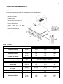 6
6
-
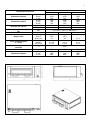 7
7
-
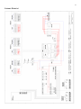 8
8
-
 9
9
-
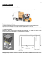 10
10
-
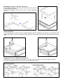 11
11
-
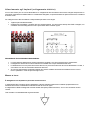 12
12
-
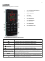 13
13
-
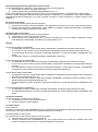 14
14
-
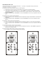 15
15
-
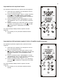 16
16
-
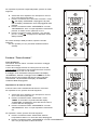 17
17
-
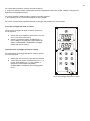 18
18
-
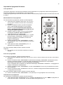 19
19
-
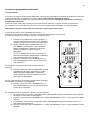 20
20
-
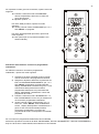 21
21
-
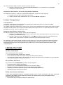 22
22
-
 23
23
-
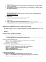 24
24
-
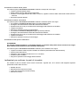 25
25
-
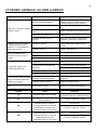 26
26
-
 27
27
-
 28
28
-
 29
29
-
 30
30
-
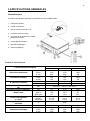 31
31
-
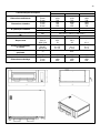 32
32
-
 33
33
-
 34
34
-
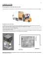 35
35
-
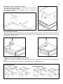 36
36
-
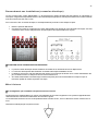 37
37
-
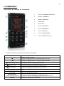 38
38
-
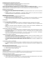 39
39
-
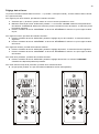 40
40
-
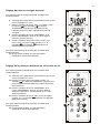 41
41
-
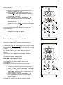 42
42
-
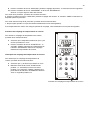 43
43
-
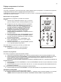 44
44
-
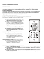 45
45
-
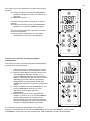 46
46
-
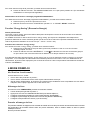 47
47
-
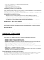 48
48
-
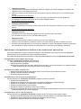 49
49
-
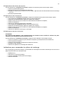 50
50
-
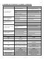 51
51
-
 52
52
-
 53
53
-
 54
54
-
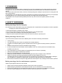 55
55
-
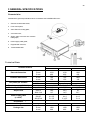 56
56
-
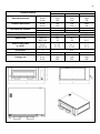 57
57
-
 58
58
-
 59
59
-
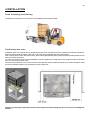 60
60
-
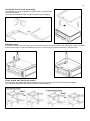 61
61
-
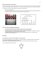 62
62
-
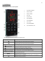 63
63
-
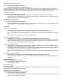 64
64
-
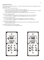 65
65
-
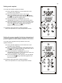 66
66
-
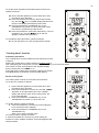 67
67
-
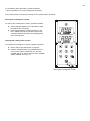 68
68
-
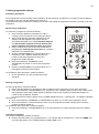 69
69
-
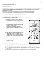 70
70
-
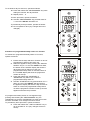 71
71
-
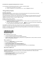 72
72
-
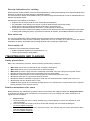 73
73
-
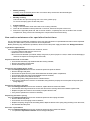 74
74
-
 75
75
-
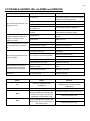 76
76
-
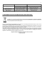 77
77
-
 78
78
-
 79
79
-
 80
80
-
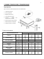 81
81
-
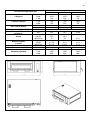 82
82
-
 83
83
-
 84
84
-
 85
85
-
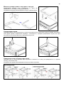 86
86
-
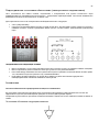 87
87
-
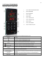 88
88
-
 89
89
-
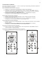 90
90
-
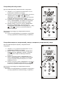 91
91
-
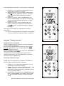 92
92
-
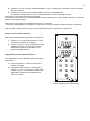 93
93
-
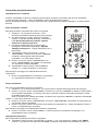 94
94
-
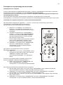 95
95
-
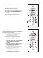 96
96
-
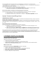 97
97
-
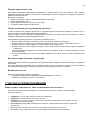 98
98
-
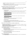 99
99
-
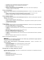 100
100
-
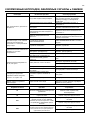 101
101
-
 102
102
-
 103
103
-
 104
104
-
 105
105
-
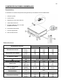 106
106
-
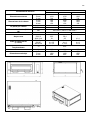 107
107
-
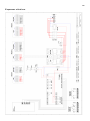 108
108
-
 109
109
-
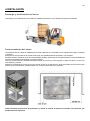 110
110
-
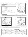 111
111
-
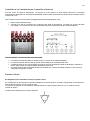 112
112
-
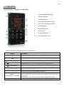 113
113
-
 114
114
-
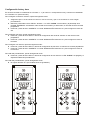 115
115
-
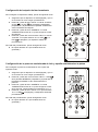 116
116
-
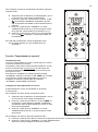 117
117
-
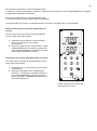 118
118
-
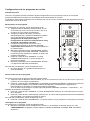 119
119
-
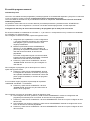 120
120
-
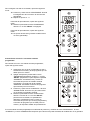 121
121
-
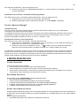 122
122
-
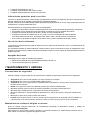 123
123
-
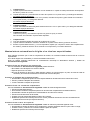 124
124
-
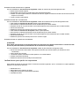 125
125
-
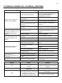 126
126
-
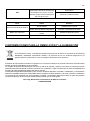 127
127
-
 128
128
-
 129
129
-
 130
130
-
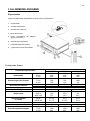 131
131
-
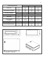 132
132
-
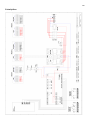 133
133
-
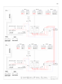 134
134
-
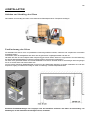 135
135
-
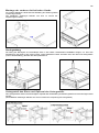 136
136
-
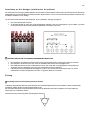 137
137
-
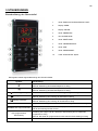 138
138
-
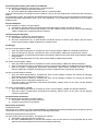 139
139
-
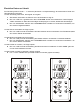 140
140
-
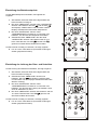 141
141
-
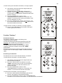 142
142
-
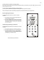 143
143
-
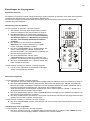 144
144
-
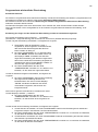 145
145
-
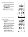 146
146
-
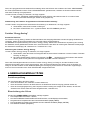 147
147
-
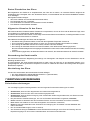 148
148
-
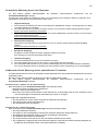 149
149
-
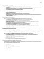 150
150
-
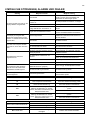 151
151
-
 152
152


