Frigidaire FFED3026TW Guía de instalación
- Categoría
- Hornos
- Tipo
- Guía de instalación
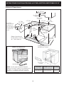
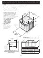
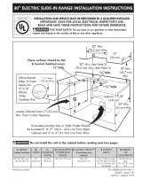
El Frigidaire FFED3026TW es una cocina eléctrica de 30 pulgadas con cuatro quemadores sellados que proporcionan una cocción rápida y uniforme. También cuenta con un horno de convección de gran capacidad que permite cocinar alimentos de manera más rápida y uniforme, gracias a su ventilador que hace circular el aire caliente dentro del horno. Además, posee una función de limpieza automática que utiliza vapor para aflojar la suciedad y la grasa, para facilitar la limpieza del horno.
El Frigidaire FFED3026TW es una cocina eléctrica de 30 pulgadas con cuatro quemadores sellados que proporcionan una cocción rápida y uniforme. También cuenta con un horno de convección de gran capacidad que permite cocinar alimentos de manera más rápida y uniforme, gracias a su ventilador que hace circular el aire caliente dentro del horno. Además, posee una función de limpieza automática que utiliza vapor para aflojar la suciedad y la grasa, para facilitar la limpieza del horno.


-
 1
1
-
 2
2
-
 3
3
-
 4
4
-
 5
5
-
 6
6
-
 7
7
-
 8
8
-
 9
9
-
 10
10
-
 11
11
-
 12
12
-
 13
13
-
 14
14
-
 15
15
-
 16
16
-
 17
17
-
 18
18
-
 19
19
-
 20
20


Frigidaire FFED3026TW Guía de instalación
- Categoría
- Hornos
- Tipo
- Guía de instalación
El Frigidaire FFED3026TW es una cocina eléctrica de 30 pulgadas con cuatro quemadores sellados que proporcionan una cocción rápida y uniforme. También cuenta con un horno de convección de gran capacidad que permite cocinar alimentos de manera más rápida y uniforme, gracias a su ventilador que hace circular el aire caliente dentro del horno. Además, posee una función de limpieza automática que utiliza vapor para aflojar la suciedad y la grasa, para facilitar la limpieza del horno.
En otros idiomas
Otros documentos
-
Kenmore 79046713602 Guía de instalación
-
 Kenmore Elite 79045013101 Guía de instalación
-
 Kenmore Elite 79041059100 Guía de instalación
-
 Kenmore Elite 79046622501 Guía de instalación
-
Kenmore 79046633602 Guía de instalación
-
 Kenmore Elite 79046822100 Guía de instalación
-
Electrolux EW30ES65GWE Instrucciones de operación
-
Kenmore 79041039804 Guía de instalación


