Shindaiwa 81645 Manual de usuario
- Categoría
- Motor
- Tipo
- Manual de usuario
Este manual también es adecuado para

SHINDAIWA OWNER’S/OPERATOR’S MANUAL
LE242 LAWN EDGER
WARNING!
Minimize the risk of injury to yourself and
others! Read this manual and familiarize yourself with
the contents. Always wear eye and hearing protection
when operating this unit.
Part Number 81645 Rev. 1/07

2
The Shindaiwa 242 Series hand held power
equipment has been designed and built to
deliver superior performance and reliability
without compromise to quality, comfort,
safety or durability.
Shindaiwa engines represent the leading
edge of high-performance engine technol-
ogy, delivering exceptionally high power
with remarkably low displacement and
weight. As an owner/operator, you’ll soon
discover for yourself why Shindaiwa is
simply in a class by itself!
Shindaiwa Inc. reserves the right to make
changes to products without prior notice,
and without obligation to make alterations
to units previously manufactured.
WARNING!
Never operate
power equipment of any
kind if you are tired or if you are under
the inuence of alcohol, drugs, medica-
tion or any other substance that could
affect your ability or judgement.
DO NOT OPERATE THIS UNIT�
IF YOU ARE TIRED, ILL OR�
UNDER THE INFLUENCE OF�
ALCOHOL, DRUGS, OR�
MEDICATION.�
�
�
�
�
Throughout this manual are special
“Attention Statements”.
IMPORTANT!
The operational procedures described
in this manual are intended to help you
get the most from this unit as well as
to protect you and others from harm.
These procedures are guidelines for safe
operation under most conditions, and are
not intended to replace any safety rules
and/or laws that may be in force in your
area. If you have questions regarding your
242 series hand held power equipment,
or if you do not understand something in
this manual, your Shindaiwa dealer will be
glad to assist you. You may also contact
Shindaiwa, Inc. at the address printed on
the back of this Manual.
Introduction
PAGE
Attention Statements ...................................2
Safety Instructions .......................................2
Safety Labels .................................................4
Product Description .....................................5
Specifications ................................................5
Assembly and Adjustments .........................6
Mixing Fuel ..................................................7
Starting the Engine ......................................8
Stopping the Engine ....................................9
Adjusting Engine Idle ..................................9
Checking Unit Condition.............................9
Using a Hand Held Edger .........................10
Adjusting the Cutting Depth .....................10
General Maintenance ................................11
Replacing the Edger Blade........................14
Long Term Storage ....................................14
Troubleshooting Guide .............................15
Emission System Warranty .......................17
Contents
IMPORTANT!
The information contained in this owner’s/
operator’s manual describes units avail-
able at the time of publication.
CAUTION!
A statement preceded by the word
“CAUTION” contains information that
should be acted upon to prevent me-
chanical damage.
WARNING!
A statement preceded by the
triangular attention symbol and
the word “WARNING” contains infor-
mation that should be acted upon to
prevent serious bodily injury.
Work Safely
Shindaiwa Edgers operate at very
high speeds and can do serious damage
or injury if they are misused or abused.
Never allow a person without training or instruc-
tion to operate this unit!
Stay Alert
You must be physically and mentally fit to
operate this unit safely.
Safety Instructions
WARNING!
Minimize the Risk of Fire
NEVER smoke or light res near
the engine.
ALWAYS stop the engine and allow it
to cool before refueling. Avoid overll-
ing and wipe off any fuel that may have
spilled.
ALWAYS inspect the unit for fuel
leaks before each use. During each
rell, check that no fuel leaks from
around the fuel cap and/or fuel tank.
If fuel leaks are evident, stop using the
unit immediately. Fuel leaks must be
repaired before using the unit.
ALWAYS move the unit to a place well
away from a fuel storage area or other
readily ammable materials before
starting the engine.
NEVER place ammable material
close to the engine mufer.
NEVER operate the engine without
the spark arrester screen in place.
WARNING!
Never make unauthorized
attachment installations. Do not use at-
tachments not approved by Shindaiwa
for use on this unit.
NOTE:
A statement preceded by the word ”NOTE”
contains information that is
handy to know and may make your
job easier.
IMPORTANT!
A statement preceded by the word
“IMPORTANT” is one that possesses
special signicance.
Attention Statements
WARNING!
The engine exhaust from this
product contains chemicals known to
the State of California to cause can-
cer, birth defects or other reproductive
harm.
50 FEET
(15m)
Read and follow this operators
manual. Failure to do so could
result in serious injury.
Wear eye and hearing protection
at all times during the operation
of this unit.
Keep bystanders at least 50 feet
(15 m) away during operation.
Beware of thrown or ricocheted
objects.
Keep feet away from blade.
Rotating blade may cause
injury. Blade may continue
to rotate after unit is shut off.

3
WARNING!
Use Good Judgment
ALWAYS wear eye protection to
shield against thrown objects.
NEVER run the engine when trans-
porting the unit.
NEVER run the engine indoors! Make
sure there is always good ventilation.
Fumes from engine exhaust can cause
serious injury or death.
ALWAYS clear your work area of trash
or hidden debris that could be thrown
back at you or toward a bystander.
ALWAYS use the proper cutting at-
tachment.
ALWAYS stop the engine immediately
if it suddenly begins to vibrate or shake.
Inspect for broken, missing or improper-
ly installed parts or attachments.
NEVER use a non-Shindaiwa ap-
proved cutting attachment.
ALWAYS keep the unit as clean as
practical. Keep it free of loose vegeta-
tion, mud, etc.
ALWAYS hold the unit rmly with both
hands when edging, and maintain con-
trol at all times.
ALWAYS keep the handles clean.
ALWAYS disconnect the spark plug
wire before performing any mainten-
ance work.
Safety Instructions The Properly Equipped Operator
Always operate with
both hands firmly gripping
the unit.
Wear close-fitting clothing to
protect legs and arms. Gloves
offer added protection and
are strongly recommended.
Do not wear clothing or
jewelry that could get caught
in machinery
or underbrush.
Secure hair so it is
above shoulder
level. NEVER
wear shorts!
Wear hearing protection devices
and a broad-brimmed hat or
helmet.
Always wear eye protection such as
goggles or safety glasses.
Keep away from the rotating blade
at all times, and never lift a moving
attachment above waist-high.
Wear appropriate footwear (non-skid boots or shoes):
do not wear open-toed shoes or sandals. Never oper-
ate the unit while barefoot!
Keep a proper footing and
do not overreach—
maintain your balance at
all times during operation.
Always make sure the
appropriate cutting attachment
shield is correctly installed
and in good condition.
Figure 1

4
Safety Labels
Figure 3
IMPORTANT
Safety and Operation Information
Labels: Make sure all information
labels are undamaged and readable.
Immediately replace damaged or miss-
ing information labels. New labels are
available from your local authorized
Shindaiwa dealer.
LE242
This label indicates the minimum
distance between front handle
and rear grip.
Be Aware of the Working Environment
Avoid long-term operation
in very hot or very cold
weather.
Make sure bystanders or observers
outside the 50-foot “danger zone”
wear eye protection.
Be extremely careful
of slippery terrain,
especially during rainy
weather.
Always make sure the ap-
propriate cutting attachment
shield is correctly installed.
If contact is made with a hard
object, stop the engine and
inspect the cutting attachment
for damage.
When operating in rocky terrain
or near electric wires or fences, use
extreme caution to avoid contact-
ing such items with the cutting
attachment.
Be constantly alert for objects
and debris that could be thrown
either from the rotating cutting
attachment or bounced from a
hard surface.
Reduce the risk of
bystanders being struck
by flying debris. Make
sure no one is within 50
feet (15 meters)—that’s
about 16 paces—of an
operating attachment.
Figure 2
50
FEET
50 FEET
(15m)
KEEP BYSTANDERS AWAY
AT LEAST 50 FEET (15m)
BEWARE OF THROWN OR
RICHOCHETED OBJECTS
KEEP AWAY FROM
ROTATING BLADE
Shindaiwa
READ THE
OPERATOR’S MANUAL
WEAR HEARING AND
ANSI Z87.1 APPROVED
EYE PROTECTION
P/N 19422-00046

5
Product Description
Figure 4
Specications
LE242 dry weight
(Including attachments)...........................................12.8 lb./5.8 kg
Engine model...........................................................................S242E
Engine type.......................................................2-cycle with catalyst
Bore x stroke.............................................1.3 x 1.1 in./33 x 28 mm
Displacement.......................................................1.5 cu. in./ 23.9 cc
Maximum power.......................................................1.0 HP/0.8 kW
@ 8000 rpm (min
-1
)
Fuel/oil ratio.............................50:1 with ISO-L-EGD or JASO FC
class 2-cycle mixing oil*
Carburetor type...............................Walbro WYK, diaphragm-type
Fuel tank capacity....................................................22.3 oz./670 ml
Ignition............................................................One-piece electronic,
transistor-controlled
Specifications are subject to change without notice.
Spark plug.....................................................................NGK BPMR6A
Air cleaner type..............................................................Non-reversible
Foam Filter Element
Starting method ............................................................................Recoil
Stopping method ................................................................Slide switch
Transmission type ................................Automatic, centrifugal clutch
w/bevel gear
EPA Emission
Compliance Period**..........................................................Category A
** The EPA emission compliance referred to on the emission compliance label
located on the engine, indicates the number of operating hours for which the
engine has been shown to meet Federal emission requirements. Category
C = 50 hours (Moderate), B = 125 hours (Intermediate) and A = 300 hours
(Extended).
* meets or exceeds these specifications and is
recommended for all Shindaiwa products.
LE242 LAWN EDGER
Outer Tube
Cutting
Attachment
Grip
Cutting
Attachment Shield
Gear case
Handle
Throttle
Trigger
Throttle
Interlock
Ignition
Switch
Fuel
Tank
IMPORTANT!
The terms “left”, “left-hand”, and “LH”;
“right”, “right-hand”, and “RH”; “front” and
“rear” refer to directions as viewed by the
operator during normal operation.
Using the accompanying illustrations as
a guide, familiarize yourself with this unit
and its various components. See Figure 4.
Understanding your unit helps ensure top
performance, long service life, and safer
operation.
WARNING!
Do not make unauthorized
modications or alterations to any of
these units or their components.
Prior to Assembly
Before assembling, make sure you have all
the components required for a complete unit:
Engine and outer tube assembly with
handle
Gearcase/Debris shield assembly
Kit containing this manual and tool kit
for routine maintenance. Tool kits vary
by model and may include a hex wrench,
a spark plug/screwdriver combination
wrench, and a scraper
.
Carefully inspect all components for damage.

6
251043
3/16-1/4 inch (4-6 mm)
Throttle Free Play
Adjust Throttle Lever Free Play
1. Loosen the air cleaner cover knob and
remove the air cleaner cover.
See Figure 7.
2. Loosen the lock nut on the cable ad-
juster. See Figure 8.
Cable
Adjuster
Assembly and Adjustments
Figure 7
Figure 8
The throttle lever free play should be ap-
proximately 3/16-1/4 inch (4-6 mm). See
Figure 6. Make sure that the throttle lever
operates smoothly without binding.
If it becomes necessary to adjust the lever
free play, follow the procedures and illustra-
tions that follow.
Figure 6
3. Turn the cable adjuster in or out as
required to obtain proper free play
3/16-1/4 inch (4-6 mm). See Figure 8.
4. Tighten the locknut.
Lock
Nut
5. Reinstall the air cleaner cover.
Assembly and Adjustments
Install Gearcase Assembly
1. Loosen gearcase clamp screw.
2. Remove the gearcase index screw.
3. Slide the gearcase oriented as shown in
Figure 5 onto the shaft tube insuring that
the flex drive is engaged in the gearcase.
NOTE:
It may be necessary to pull the flex cable out
from the shaft tube, engage into the gearcase
and then slide the assembly onto the shaft tube.
4. Reinstall the index screw and tighten
securely.
5. Tighten the clamp screw and torque to
52 – 69 inch pounds.
Figure 5

7
1. Place the edger on a flat, level surface.
2. Clear any dirt or other debris from
around the fuel filler cap.
3. Remove the fuel cap, and fill the tank
with clean, fresh fuel.
4. Reinstall the fuel filler cap and tighten
firmly.
Filling the Fuel Tank
WARNING!
Minimize the risk of re!
STOP engine before refueling.
ALWAYS allow the engine to cool
before refueling!
Wipe all spilled fuel and move the
engine at least 10 feet (3 meters)
from the fueling point and source
before restarting!
NEVER start or operate this unit if
there is a fuel leak.
NEVER start or operate this unit if
the carburetor, fuel lines, fuel tank
and/or fuel tank cap are damaged.
NEVER smoke or light any res
near the engine or fuel source!
NEVER place any ammable ma-
terial near the engine mufer!
NEVER operate the engine with-
out the mufer and spark arrester
in good working condition.
Mixing Fuel
CAUTION!
This engine is designed to operate on
a 50:1 mixture consisting of unleaded
gasoline and ISO-L-EGD or JASO FC
class 2-cycle mixing oil only. Use of
non-approved mixing oils can lead to
excessive carbon deposits.
CAUTION!
Some types of gasoline contain alcohol
as an oxygenate. Oxygenated gaso-
line may cause increased operating
temperatures. Under certain condi-
tions, alcohol-based gasoline may also
reduce the lubricating qualities of some
2-cycle mixing oils. Never use any
type of gasoline containing more than
10% alcohol by volume! Generic oils
and some outboard oils may not be
intended for use in high-performance
2-cycle engines, and should never be
used in your Shindaiwa engine
.
Use only fresh, clean unleaded gasoline
with a pump octane of 87 or higher.
Mix all fuel with a 2-cycle air-cooled mix-
ing oil that meets or exceeds
ISO-L-EGD and/or JASO FC classified
oils at 50:1 gasoline/oil ratio.
Examples of 50:1 mixing quantities
1 gallon of gasoline to 2.6 oz. mixing oil
5 liters of gasoline to 100 ml. mixing oil
IMPORTANT!
Mix only enough fuel for your immediate
needs! If fuel must be stored longer than
30 days and oil with fuel stabilizer
is not used, it should rst be treated with a
fuel stabilizer such as STA-BIL™.
Oil is a registered JASO FC clas-
sified oil and also meets or exceeds ISO-L-
EGD performance requirements. Shindaiwa
One is recommended for use in all Shindaiwa
low emissions engines.Shindaiwa One also
includes a fuel stabilizer.

8
WARNING!
Never start the engine from
the operating position.
When the Engine Starts...
After the engine starts, allow the engine
to warm up at idle 2 or 3 minutes before
operating the unit.
Advancing the throttle makes the cut-
ting attachment turn faster; releasing
the throttle permits the attachment to
stop turning. If the cutting attachment
continues to rotate when the engine
returns to idle, carburetor idle speed
should be adjusted (see “Adjusting
Engine Idle” on next page).
IMPORTANT!
If the engine fails to start after several at-
tempts with the choke in the closed posi-
tion, the engine may be ooded with fuel.
If ooding is suspected, move the choke
lever to the open position and repeatedly
pull the recoil starter to remove excess
fuel and start the engine. If the engine still
fails to start, refer to the troubleshooting
section of this manual.
WARNING!
The cutting attachment may
rotate when the engine is started!
5. When the engine starts, slowly move the
choke lever to the “OPEN” position. See
Figure 13. (If the engine stops after the
initial start, close the choke and restart.)
Starting the Engine
2. Press the primer bulb until fuel can be
seen flowing in the transparent return
tube.
IMPORTANT!!
Engine ignition is controlled by a two position switch mounted on the throttle housing labeled, “I” for ON or START and
“O” for OFF or STOP.
Figure 9
IMPORTANT!
The primer system only pushes fuel
through the carburetor. Repeatedly
pressing the primer bulb will not ood the
engine with fuel.
XST013
4. While holding the outer tube firmly with
left hand. Use your other hand to slowly
pull the recoil starter handle until resis-
tance is felt, then pull quickly to start the
engine.
Make sure the
cutting attach-
ment
is clear of ob-
structions!
Figure 12
CAUTION!
Do not pull the recoil starter to the end
of the rope travel. Pulling the recoil
starter to the end of the rope travel
can damage the starter.
ON
1. Slide the ignition switch to the “ON”
position. See Figure 9.
3. Set the choke lever to the CLOSED
position if engine is cold.
Primer Bulb
Return Tube
Figure 10
Closed
Figure 11
Figure 13
Open

9
251029
Idle the engine briefly before stopping
(about 2 minutes), then slide the ignition
switch to the “O” (Engine OFF) position.
Stopping the Engine
Adjusting Engine Idle
Figure 14
OFF
The engine must return to idle speed
whenever the throttle lever is released.
Idle speed is adjustable, and must be set
low enough to permit the engine clutch to
disengage the cutting attachment.
Idle Speed Adjustment
WARNING!
The cutting attachment must
NEVER rotate at engine idle! If
the idle speed cannot be adjusted by
the procedure described here, return
the trimmer to your Shindaiwa dealer for
inspection.
1. Place the trimmer on the ground, then
start the engine, and then allow it to idle
2-3 minutes until warm.
2. If the attachment rotates when the
engine is at idle, reduce the idle speed
by turning the idle adjustment screw
counter-clockwise. See Figure 15.
3. If a tachometer is available, the engine idle
speed should be final adjusted to 3,000
(±250) rpm (min
-1
).
4. Carburetor fuel mixture adjustments are
preset at factory and cannot be serviced
in the field.
NEVER operate the unit with the cut-
ting attachment shield or other protective
devices removed!
WARNING!
A cutting attachment shield or
other protective device is no guaran-
tee of protection against ricochet. YOU
MUST ALWAYS GUARD AGAINST FLY-
ING DEBRIS!
Use only authorized Shindaiwa parts
and accessories with your Shindaiwa trim-
mer. Do not make modifications to this unit
without written approval from Shindaiwa, Inc.
Checking Unit Condition
ALWAYS make sure the cutting attach-
ment is properly installed and firmly tight-
ened before operation.
NEVER use a cracked or warped cutting at-
tachment: replace it with a serviceable one.
ALWAYS make sure the cutting attach-
ment fits properly into the appropriate
attachment holder. If a properly installed at-
tachment vibrates, replace the attachment
with new one and re-check.
ALWAYS stop the engine immediately and
check for damage if you strike a foreign
object or if the unit becomes tangled. Do
not operate with broken or damaged equip-
ment.
NEVER allow the engine to run at high
RPM without a load. Doing so could dam-
age the engine.
NEVER operate a unit with worn or dam-
aged fasteners or attachment holders.
Figure 15
Idle Adjusting
Screw

10
Using a Hand-held Edger
Do not pull the unit backward over the
ground with the engine running. Doing
so will tend to bury the blade.
Regular and frequent use of the edger
will make a neater lawn, and a frequently
trimmed edge will be easier to maintain.
Before edging, make sure the area is
soft enough so the blade does not bog
down. If necessary, water the area before
edging.
Remove debris and other obstacles that
could be thrown by the rotating blade.
Plan your work so the edger blade is
always on your right-hand side.
Begin each pass by positioning the unit
over the work, and with the engine run-
ning at about half-throttle. Slowly lower
the blade to the ground while applying
full throttle. See Figure 16.
Do not move the edger into the work so
fast that the engine or blade bogs down.
Guidelines for Operating the Edger
Figure 16
WARNING!
Wear eye protection, long pants,
and boots when operating this
machine!
Whenever you strike a hard
object with the blade, always stop
the edger and carefully inspect
the blade for damage. NEVER
OPERATE THE EDGER WITH A
DAMAGED BLADE!
CAUTION!
Low-speed edging can lead to prema-
ture clutch failure.
26021
The edger’s depth of cut is controlled by a
combination of operator height, blade wear,
and the positioning of the edger’s guide
wheel.
To adjust blade height:
1. Loosen the guide wheel adjusting knob.
See Figure 17.
2. Raise or lower the guide wheel to the
desired setting. See Figure 17a.
3. Tighten the guide wheel adjusting knob
firmly . See Figure 17.
Adjusting the Cutting Depth
Guide Wheel
Adjusting knob
The numbers are for
reference only; they do
NOT refer to depth in
inches
Figure17
Figure 17a
Guide Wheel
WARNING!
Never adjust the guide wheel while the
engine is running.
NOTE
Guide wheel adjustment is also required to
compensate for blade wear.
WARNING!
Use only Shindaiwa replace-
ment edger blades.

11
WARNING!
Before performing any mainte-
nance, repair or cleaning work on the
unit, make sure the engine and cutting
attachment are completely stopped.
Disconnect the spark plug wire before
performing service or maintenance work.
WARNING!
Non-standard parts may not oper-
ate properly with your unit and may cause
damage and lead to personal injury.
General Maintenance
IMPORTANT!
MAINTENANCE, REPLACEMENT OR
REPAIR OF EMISSION CONTROL
DEVICES AND SYSTEMS MAY BE
PERFORMED BY ANY REPAIR
ESTABLISHMENT OR INDIVIDUAL;
HOWEVER, WARRANTY REPAIRS
MUST BE PERFORMED BY A DEALER
OR SERVICE CENTER AUTHORIZED
BY SHINDAIWA CORP. THE USE OF
PARTS THAT ARE NOT EQUIVALENT IN
PERFORMANCE AND DURABILITY TO
AUTHORIZED PARTS MAY IMPAIR THE
EFFECTIVENESS OF THE EMISSION
CONTROL SYSTEM AND MAY HAVE
A BEARING ON THE OUTCOME OF A
WARRANTY CLAIM.
Mufer
This unit must never be operated with a
faulty or missing spark arrester or muf-
fler. Make sure the muffler is well secured
and in good condition. A worn or damaged
muffler is a fire hazard and may also cause
hearing loss.
Spark Plug
Keep the spark plug and wire connections
tight and clean.
Fasteners
Make sure nuts, bolts, and screws (except
carburetor adjusting screws) are tight.
Daily Maintenance
Prior to each work day, perform the
following:
NOTE:
Using non-standard replacement parts could
invalidate your Shindaiwa warranty.
Remove dirt or debris from the engine,
check the cooling fins and air cleaner for
clogging and clean them as necessary.
10-Hour Maintenance
Every 10 hours of operation (more fre-
quently in dusty or dirty conditions):
Remove the air cleaner element.
See Figure 18. Clean or replace as
necessary. To clean element: wash it
thoroughly in soap and water. Let it
dry before reinstalling the element.
CAUTION!
Do not operate the unit if the air
cleaner or element is damaged, or if
the element is wet.
Figure 18
Carefully remove any accumulation of
dirt or debris from the muffler or the
fuel tank. Dirt build-up in these areas
could cause engine overheating, induce
premature wear, or create a fire hazard.
Check for loose or missing screws or
components. Make sure the cutting at-
tachment is securely fastened.
Check the entire unit for leaking fuel or
grease.
Never repair a damaged blade
by welding, straightening, or by
modifying its shape. An altered
blade may break during operation,
resulting in serious personal injury.
Blades are not interchangeable be-
tween Shindaiwa edgers and trimmer/
brushcutter models. Operating any
unit with a blade or attachment not
approved for that unit can be hazard-
ous and may cause serious injury.
WARNING!
Unscrew
Fastener
Remove and
clean or replace
the element

12
Every 10 to 15 hours of operation:
Remove and clean the spark plug. Adjust
the spark plug electrode gap to 0.024
0.028 inch (0.6-0.7 mm). If the spark
plug must be replaced, use only an
NGK BPMR6A or equivalent resistor
type spark plug of the correct heat
range. See Figure 19.
CAUTION!
Before removing the spark plug, clean
the area around the plug to prevent
dirt and debris from getting into the
engine’s internal parts.
10/15-Hour Maintenance
Figure 19
NOTE:
The NGK
BPMR6A
also meets the require-
ments for electro magnetic compliance (EMC).
Every 50 hours of operation (more
frequently in dusty or dirty conditions):
Remove the cylinder cover and clean
grass and dirt from the cover and cylin-
der fins.
Remove the cutting attachment, cutting
attachment holder and gear shaft collar.
Remove the filler plug from the side
of the gearcase and press new grease
into the gearcase until grease is pushed
out. Use only lithium-base grease such
as Shindaiwa Gear Case Lubricant or
equivalent. See figure 20.
50-Hour Maintenance
Use a hooked wire to extract the fuel filter
from inside the fuel tank. See figure 21.
Lubricate the Flexible Shaft.
Lack of lubrication will cause rapid wear to
the flexible shaft and also to the shaft tube
liner, resulting in increased vibration and
greatly decreased service life. Remove and
lubricate the flexible shaft as follows:
1. Loosen the gearcase clamp screw.
2. Remove the gearcase index screw.
3. Slide the gearcase and shield assembly
from the shaft tube.
4. Pull the flexible shaft from the shaft tube
assembly, and clean the shaft thorough-
ly in solvent.
5. Inspect the shaft carefully, and replace
if worn or damaged. If flexible shaft
is worn and needs replacement, liner
should also be replaced.
6. Coat the entire length of the shaft with
Shindaiwa Premium Gearcase Lube (or
equivalent), and reinstall the shaft in the
shaft tube assembly.
NOTE:
For extended shaft life, the flexible cable
should be reversed end-for-end during the
reinstallation process.
7. Insert the flexible shaft into the female
end of the gearcase pinion.
8. Install the gearcase on the shaft tube in
the reverse order of removal.
Gearcase Index
Screw
Shaft Tube
Flexible Shaft
CAUTION!
Make sure you do not pierce the fuel
line with the end of the hooked wire.
The line is delicate and can be dam-
aged easily.
Figure 22
New
Grease
Figure 20
Old
Grease
Shaft
Bolt
Bolt
Guard
Holder
A
Holder
B
Output
Shaft Collar
Blade
Remove and replace the filter element.
Before reinstalling the new filter ele-
ment, inspect the condition of all the
fuel system components (fuel pick-up
line, fuel return line, tank vent line, tank
vent, fuel cap and fuel tank). If damage,
splitting or deterioration is noted, the
unit should be removed from service
until it can be inspected or repaired by a
Shindaiwa-trained service technician.
XST021
Clean the
spark plug and
check the gap
at the electrode.
0.024–0.028 inch
(0.6–0.7 mm)
Figure 21
Filter Element
Hooked
Wire

13
Gearcase Protector
(P/N 72958-16210)
Nut
Inspect the Gearcase Protector
The metal gearcase protector (p/n 72958-
16210) is installed to protect the gearcase
flange from damage when working close to
sidewalks or other abrasive surfaces, and
should be routinely inspected for damage
or excessive wear.
When replacing the protector, inspect to be
sure that both of the protector mounting
screws are firmly tightened and each screw
is locked in place with a nut as shown.
CAUTION!
The D-shaped shim washer must be
positioned with its at edge toward the
shaft tube.
D-shaped
Shim Washer
Flat
(toward tube)
Shaft
Tube
Gearcase
26024
Figure 23
Figure 24
50-Hour Maintenance (continued)
135-hour Maintenance
Every 135 hours of operation,
remove and clean the muffler.
WARNING!
Never operate this trimmer
with a damaged or missing mufer or
spark arrester! Operating with missing
or damaged exhaust components is
a re hazard, and can also damage
your hearing!
1. Remove the spark plug boot.
2. With a 3 mm hex wrench remove the 1
muffler cover and 3 engine cover screws
and the engine cover. See Figure 25.
3. With a Phillips type screwdriver remove
the 5 screws holding the spark arrester
screen and cover to the muffler. See
Figure 25.
4. Remove the screen and clean it with a
stiff bristle brush.
5. With a 4 mm hex wrench remove the 3
muffler bolts and the muffler.
See Figure 25.
6. Inspect the cylinder exhaust port for any
carbon buildup.
7. Gently tap the muffler on a wood surface
to dislodge any loose carbon.
Engine Cover
Screws
IMPORTANT!
If you note excessive carbon buildup, consult
with an authorized Shindaiwa servicing
dealer.
8. Reassemble the spark arrester, muffler
and engine cover in the reverse order of
disassembly.
Figure 25
Muffler
Cover
Engine
Cover
Muffler
Cover Screw
Spark Arrester
Screen
Muffler
Gasket
Muffler
Spark Arrester
Cover
Gasket
Screws
Mufer
Screws
Outlet

14
Long Term Storage
Remove the spark plug and pour about
1/4 ounce of 2-cycle mixing oil into the
cylinder through the spark plug hole.
Slowly pull the recoil starter 2 or 3 times
so oil will evenly coat the interior of the
engine. Reinstall the spark plug.
Before storing the unit, repair or replace
any worn or damaged parts.
Remove the air cleaner element from the
carburetor and clean it thoroughly with
soap and water. Let dry and reassemble
the element.
Store the unit in a clean, dust-free area.
Whenever the unit will not be used for 30
days or longer, use the following proce-
dures to prepare it for storage:
Clean external parts thoroughly.
Drain all the fuel from the fuel tank.
IMPORTANT!
All stored fuels should be stabilized with a
fuel stabilizer such as STA-BIL™, if
oil with fuel stabilizer is not used.
Remove the remaining fuel from the fuel
lines and carburetor.
1. Prime the primer bulb until no more fuel
is passing through.
2. Start and run the engine until it
stops running.
3. Repeat steps 1 and 2 until the engine will
no longer start.
CAUTION!
Gasoline stored in the carburetor
for extended periods can cause hard
starting and could also lead to
increased service and maintenance
cost.
Replacing the Edger Blade
26118
Holder A
Edger
Blade
Lock the
shaft
Holder B
Output Shaft
Bolt
Bolt
Guard
Figure 26
WARNING!
Always wear gloves when handling the
edger blade.
1. Align the hole in holder A with the
matching hole in the gearcase and then
use the hex wrench to temporarily lock
the output shaft.
2. Use the combination wrench to loosen
the shaft bolt then remove the output
shaft bolt, Holder B and the edger blade
from the gearcase.
3. Mount the edger blade and holder B
onto the shaft, and then install the bolt
guard and shaft bolt (turn bolt counter-
clockwise to install). See Figure 26.
4. Align the hole in holder A with the
matching hole in the gearcase, and then
use the hex wrench to temporarily lock
the output shaft. See Figure 26.
5. Use the combination wrench to firmly
tighten the shaft bolt. Remove the hex
wrench. See Figure 26.

15
Troubleshooting Guide
ENGINE DOES NOT START
Does the engine crank?
Faulty recoil starter.
Fluid in the crankcase.
Internal damage.
Consult with an authorized servicing dealer.
Consult with an authorized servicing dealer.
Consult with an authorized servicing dealer.
NO
Good compression?
Loose spark plug.
Excess wear on cylinder, piston, rings.
Tighten and re-test.
NO
YES
Does the tank contain
fresh fuel of the proper
grade?
Refill with fresh, clean unleaded gasoline with
a pump octane of 87 or higher mixed with
a 2-cycle air cooled mixing oil that meets or
exceeds ISO-L-EGD and/or JASO FC classified
oils at 50:1 gasoline/oil ratio.
Fuel incorrect, stale or contaminated;
mixture incorrect.
NO
YES
Is fuel visible and moving
in the return line when
priming?
Check for clogged fuel filter and/or vent.
Priming pump not functioning properly.
Replace fuel filter or vent as required; restart.
Consult with an authorized servicing dealer.
NO
Is there spark at the spark
plug wire terminal?
The ignition switch is in “O” (OFF)
position.
Shorted ignition ground.
Faulty ignition unit.
Move switch to “I” (ON) position and restart.
NO
YES
YES
Check the spark plug.
If the plug is wet, excess fuel may be in
the cylinder.
The plug is fouled or improperly gapped.
The plug is damaged internally or of the
wrong size.
Crank the engine with the plug removed,
reinstall the plug, and restart.
Clean and regap the plug to 0.024 - 0.028
inch (0.6 - 0.7 mm). Restart.
Replace the plug with an NGK BPMR6A or
equivalent resistor type spark plug of the
correct heat range. Set spark plug electrode
gap to 0.024-0.028 inch (0.6-0.7 mm).
YES
What To Check Possible Cause Remedy
Is the engine overheating?
Operator is overworking the unit.
Carburetor mixture is too lean.
Improper fuel ratio.
Fan, fan cover, cylinder fins dirty
or damaged.
Carbon deposits on the piston or in
the muffler.
Cut at a slower rate.
Consult with an authorized servicing dealer.
Refill with fresh, clean unleaded gasoline with
a pump octane of 87 or higher mixed with
a 2-cycle air cooled mixing oil that meets or
exceeds ISO-L-EGD and/or JASO FC classified
oils at 50:1 gasoline/oil ratio.
Clean, repair or replace as necessary.
Consult with an authorized servicing dealer.
What To Check Possible Cause Remedy
Engine is rough at all
speeds. May also have
black smoke and/or
unburned fuel at the
exhaust.
Clogged air cleaner element.
Loose or damaged spark plug.
Air leakage or clogged fuel line.
Water in the fuel.
Piston seizure.
Faulty carburetor and/or diaphragm.
Service the air cleaner element.
Tighten or replace.
Repair or replace filter and/or fuel line.
Replace the fuel. See page 7.
Consult with an authorized servicing dealer.
Engine is knocking.
Overheating condition.
Improper fuel.
Carbon deposits in the combustion
chamber.
See above.
Check fuel octane rating; check for presence of
alcohol in the fuel (pg. 7). Refuel as necessary.
Consult with an authorized servicing dealer.
LOW POWER OUTPUT

16
Poor acceleration.
Clogged air filter.
Clogged fuel filter.
Lean fuel/air mixture.
Idle speed set too low.
Clean the air filter.
Replace the fuel filter.
Consult with an authorized servicing dealer.
Adjust: 3,000 (±250) RPM (min
-1
).
Symptom Possible Cause Remedy
Engine stops abruptly.
Switch turned off.
Fuel tank empty.
Clogged fuel filter.
Water in the fuel.
Shorted spark plug or loose terminal.
Ignition failure.
Piston seizure.
Reset the switch and restart.
Refuel. See page 7.
Replace fuel filter.
Drain; replace with clean fuel. See page 7.
Clean and replace spark plug, tighten
the terminal.
Replace the ignition unit.
Consult with an authorized servicing dealer.
Engine difficult to shut off.
Ground (stop) wire is disconnected or
switch is defective.
Overheating due to incorrect spark plug.
Overheated engine.
Test and replace as required.
Idle engine until cool.
Clean and regap the plug to 0.024 - 0.028
inch (0.6 - 0.7 mm). Correct plug: NGK BPMR6A
or equivalent resistor type spark plug of the
correct range.
Idle engine until cool.
Cutting attachment
rotates at engine idle.
Set idle: 3,000 (±250) RPM (min
-1
).
Replace spring/shoes as required, check
idle speed.
Inspect and re-tighten holders securely.
Engine will not idle down.
Engine idle set too high.
Engine has an air leak.
Set idle: 3,000 (±250) RPM (min
-1
).
Consult with an authorized servicing dealer.
Engine idle too high.
Broken clutch spring or worn clutch
spring boss.
Loose attachment holder.
Troubleshooting Guide (continued)
ADDITIONAL PROBLEMS
ADDITIONAL PROBLEMS
Symptom Possible Cause Remedy
Excessive vibration.
Warped or damaged cutting attachment.
Loose gearcase.
Bent main shaft/worn or damaged
liner.
Inspect and replace attachment as required.
Tighten gearcase securely.
Inspect and replace as necessary.
Cutting attachment will
not rotate.
Shaft not installed in powerhead or
gearcase.
Broken shaft.
Damaged gearcase.
Inspect and reinstall as required.
Consult with an authorized servicing dealer.

17
Shindaiwa Corporation warrants to the initial purchaser and each
subsequent owner, that this utility equipment engine (herein
engine) is designed, built and equipped to conform at the time of
initial sale, to all applicable regulations of the U.S. Environmental
Protection Agency (EPA), and that the engine is free of defects in
materials and workmanship that would cause this engine to fail
to conform with EPA regulations during its warranty period. This
emission warranty is applicable in all States, except the State of
California.
For parts listed under PARTS COVERED, the dealer authorized by
Shindaiwa Corporation will, at no cost to you, make the necessary
diagnosis, repair, or replacement of any defective emission-related
component to ensure that the engine complies with applicable U.S.
EPA regulations.
MANUFACTURERS WARRANTY COVERAGE
When sold within the U.S., this engine’s emission control system is
warranted for a period of two (2) years from the date this product is first
delivered to the original retail purchaser.
OWNER’S WARRANTY RESPONSIBILITIES
As the engine owner, you are responsible for the performance of the re-
quired maintenance listed in your owner’s manual. Shindaiwa Corporation
recommends that you retain all receipts covering maintenance on your
engine, but Shindaiwa Corporation cannot deny a warranty claim solely
for the lack of receipts or for your failure to ensure the performance of all
scheduled maintenance.
As the engine owner, you should however be aware that Shindaiwa
Corporation may deny your warranty coverage if your engine or a part
has failed due to abuse, neglect, improper maintenance or unapproved
modifications.
You are responsible for presenting your engine to the nearest dealer
authorized by Shindaiwa Corporation when a problem exists.
If your Shindaiwa Dealer is unable to answer questions regarding your
warranty rights and responsibilities, you should then contact your
Shindaiwa Distributor.
For the name and telephone number of the Shindaiwa Distributor in your
area, please call Shindaiwa Inc. at (503) 692-3070 between the hours of
8:00 AM and 5:00 PM Pacific Standard Time.
PARTS COVERED
Listed below are the parts covered by the Federal Emission Design and
Defect Warranty. Some parts listed below may require scheduled main-
tenance and are warranted up to the first scheduled replacement of that
part. The warranted parts include:
1. Carburetor Internal Components
• Valve Assembly-throttle, Jet, Metering Diaphragm
2. Ignition System Components
• Ignition Coil
• Flywheel Rotor
The emission control system for your particular Shindaiwa engine may
also include certain related hoses and connectors.
The following statement only applies to United States and its territories
Shindaiwa Corporation
Federal Emission Design And Defect Limited Warranty
Utility And Lawn And Garden Engines
LIMITATIONS
The Federal Emission Design and Defect Warranty shall not cover any of
the following:
(a) conditions resulting from tampering, misuse, improper adjustment
(unless they were made by the dealer or service center authorized
by Shindaiwa Corporation during a warranty repair), alteration,
accident, failure to use the recommended fuel and oil, or not per-
forming required maintenance services,
(b) the replacement parts used for required maintenance services,
(c) consequential parts used for required maintenance services,
(d) diagnosis and inspection fees that do not result in eligible warranty
service being performed, and
(e) any non-authorized replacement part, or malfunction of authorized
parts due to use of non-authorized parts.
MAINTENANCE AND REPAIR REQUIREMENTS
You are responsible for the proper use and maintenance of the engine. You
should keep all receipts and maintenance records covering the perfor-
mance of regular maintenance in the event questions arise. These receipts
and maintenance records should be transferred to each subsequent owner
of the engine. Shindaiwa Corporation reserves the right to deny warranty
coverage if the owner has not properly maintained the engine. Shindaiwa
Corporation will not deny warranty repairs, however, solely because of the
lack of repair, maintenance or failure to keep maintenance records.
MAINTENANCE, REPLACEMENT OR REPAIR OF EMISSION
CONTROL DEVICES AND SYSTEMS MAY BE PERFORMED BY ANY
REPAIR ESTABLISHMENT OR INDIVIDUAL; HOWEVER, WARRANTY
REPAIRS MUST BE PERFORMED BY A DEALER OR SERVICE CENTER
AUTHORIZED BY SHINDAIWA CORPORATION THE USE OF PARTS
THAT ARE NOT EQUIVALENT IN PERFORMANCE AND DURABILITY
TO AUTHORIZED PARTS MAY IMPAIR THE EFFECTIVENESS OF THE
EMISSION CONTROL SYSTEM AND MAY HAVE A BEARING ON THE
OUTCOME OF A WARRANTY CLAIM.
If other than the parts authorized by Shindaiwa Corporation are used for
maintenance replacements or for the repair of components affecting emis-
sion control, you should assure yourself that such parts are warranted by
their manufacturer to be equivalent to the parts authorized by Shindaiwa
Corporation in their performance and durability.
OBTAINING WARRANTY SERVICE
All repairs qualifying under this limited warranty must be performed by a
dealer authorized by Shindaiwa Corporation
If any emission-related part is found defective during the warranty period,
it is your responsibility to present the product to an authorized Shindaiwa
dealer. Bring your sales receipts showing the date of purchase for this
engine. The dealer authorized by Shindaiwa Corporation will perform the
necessary repairs or adjustments within a reasonable amount of time and
furnish you with a copy of the repair order. All parts and accessories re-
placed under this warranty become the property of Shindaiwa Corporation
To locate an authorized Shindaiwa dealer near you, contact your
Shindaiwa Distributor. For the name and telephone number of the
Shindaiwa Distributor in your area, please call Shindaiwa Inc. at (503) 692-
3070 between the hours of 8:00 AM and 5:00 PM Pacific Standard Time.
THIS WARRANTY IS ADMINISTERED BY
Shindaiwa Inc.
11975 S.W. Herman Rd.
Tualatin OR. 97062
(503) 692-3070

18
Shindaiwa Inc.
11975 S.W. Herman Rd.
Tualatin, Oregon 97062 USA
Telephone: 503 692-3070
Fax: 503 692-6696
www.shindaiwa.com
NOTES
Shindaiwa Corp.
Head Office:
6-2-11, Ozuka-Nishi
Asaminami-Ku, Hiroshima
731-3167, Japan
Telephone: 81-82-849-2220
Fax: 81-82-849-2481
©2007 Shindaiwa, Inc.
Part Number 81645
Revision 1/07
Shindaiwa is a registered trademark
of Shindaiwa, Inc.
Specifications subject to change without notice.

18
Shindaiwa Inc.
11975 S.W. Herman Rd.
Tualatin, Oregon 97062 USA
Teléfono: 503 692-3070
Fax: 503 692-6696
www.shindaiwa.com
NOTAS
Shindaiwa Corporation
Head Office:
6-2-11, Ozuka-Nishi
Asaminami-Ku, Hiroshima
731-3167, Japan
Teléfono: 81-82-849-2220
Fax: 81-82-849-2481
©2007 Shindaiwa, Inc.
Despida el Número 81645
Revisión 1/07
Shindaiwa es una marca
registrada registrada de
Shindaiwa, Inc.
Especificaciones sujetas a
cambio sin previo aviso.

17
Shindaiwa Corporation garantiza al comprador inicial y a cada
propietario siguiente, que este motor para equipos de uso general
(de aquí en adelante motor) está diseñado, fabricado y equipado para
cumplir, en el momento de la venta inicial, con todas los reglamentos
vigentes de la Administración de Protección Ambiental de EE.UU.
(EPA) y que no tiene defectos materiales ni de mano de obra que
pudieran hacer que el motor no cumpla con las reglamentaciones de la
EPA durante el período de vigencia de la garantía. Esta garantía sobre
normas de emisión rige para todos los estados, excepto para el Estado de
California.
Para las piezas listadas en PIEZAS CUBIERTAS, el Distribuidor
autorizado por Shindaiwa Corporation efectuará, sin costo para el
propietario, los diagnósticos, reparaciones o reemplazos necesarios de
cualquier componente defectuoso en relación con las emisiones para
asegurar que el motor cumpla con las reglamentaciones de la EPA de
EE.UU. aplicables.
COBERTURA DE LA GARANTÍA DEL FABRICANTE
Cuando este equipo se vende en EE.UU., el sistema de control de
emisiones del mismo está garantizado por un período de 2 (dos) años a
partir de la fecha en que el producto haya sido entregado por primera vez
al comprador minorista original.
RESPONSABILIDADES DEL PROPIETARIO RESPECTO DE LA
GARANTÍA
Como propietario del motor, usted es responsable de la realización del
mantenimiento requerido listado en su manual del propietario. Shindaiwa
Corporation le recomienda conservar todos los comprobantes que
cubran el mantenimiento de su motor, pero Shindaiwa Corporation no
puede negar una reclamación de garantía exclusivamente debido a la
falta de comprobantes o porque usted no pueda asegurar la realización
de todos los mantenimientos programados.
Como propietario del motor, usted deberá sin embargo estar enterado
de que Shindaiwa Corporation podrá negarle cobertura de garantía si
el motor o alguna pieza ha fallado debido a uso abusivo, negligencia,
mantenimiento inadecuado o modificaciones no autorizadas.
Usted es responsable de la presentación del motor al distribuidor
autorizado de Shindaiwa Corporation más cercano cuando exista algún
problema.
Si el distribuidor Shindaiwa no puede responder su pregunta con
respecto a sus derechos y responsabilidades de garantía, deberá
entonces comunicarse con su distribuidor regional de Shindaiwa.
Para obtener el nombre y el número telefónico del distribuidor
de Shindaiwa en su localidad, comuníquese con Shindaiwa Inc., al
(503) 692-3070 de 8:00 a.m. a 5:00 p.m., hora del Pacífico.
PIEZAS CUBIERTAS
A continuación se listan las piezas cubiertas por la garantía de
diseño federal de emisiones y defectos. Algunas partes mencionadas
a continuación pueden requerir mantenimiento periódico y están
garantizadas hasta el primer reemplazo programado de las mismas. Las
partes garantizadas incluyen:
1. Componentes internos del carburador
• Armado y medición del chorro y el diafragma
2. Componentes del sistema de encendido
• Bobina de encendido
• Rotor del volante
El sistema de control de emisiones del motor Shindaiwa puede también
incluir ciertas mangueras y conexiones afines.
LIMITACIONES
La garantía por diseño federal de emisiones y defectos no cubrirá nada
de lo siguiente:
(a) Condiciones que resulten de una intervención no autorizada,
un mal uso, un ajuste inapropiado (a menos de que los hubieran
efectuado un distribuidor o un centro de servicio autorizado
de Shindaiwa Corporation, en el curso de una reparación de
garantía), una alteración, accidente, omisión en el uso del
combustible y aceite recomendados o de una omisión en el
cumplimiento de los servicios de mantenimiento requeridos,
(b) Los repuestos usados para los servicios de mantenimiento
requeridos,
(c) Partes consecuenciales utilizadas para efectuar los servicios de
mantenimiento requeridos,
(d) Cuotas de diagnóstico e inspección que no resulten en servicios
cubiertos por la garantía,
(e) Todo repuesto no autorizado o la falla de partes autorizadas que
pudieran deberse al uso de partes no autorizadas.
REQUISITOS DE MANTENIMIENTO Y REPARACIÓN
Usted es responsable del uso y mantenimiento correctos del motor.
Usted deberá conservar todos los comprobantes y registros de
mantenimiento que cubran la realización de mantenimiento regular
en caso de que surjan preguntas. Estos comprobantes y los registros
de mantenimiento deberán ser transferidos a cada propietario
subsiguiente del motor. Shindaiwa Corporation se reserva el derecho
a negar la cobertura de garantía si el propietario no ha mantenido
correctamente el motor. Shindaiwa Corporation, sin embargo, no negará
reparaciones bajo garantía por el solo hecho de no haberse efectuado
reparaciones o mantenimiento o por la omisión de mantener registros de
mantenimiento.
EL MANTENIMIENTO, REEMPLAZO O REPARACIÓN DE
DISPOSITIVOS Y SISTEMAS DE CONTROL DE EMISIONES PUEDE
SER REALIZADO POR CUALQUIER ESTABLECIMIENTO O PERSONA
DEDICADOS A ELLO; SIN EMBARGO, LAS REPARACIONES
CUBIERTAS POR LA GARANTÍA DEBEN SER LLEVADAS A CABO
POR UN DISTRIBUIDOR O CENTRO DE SERVICIO AUTORIZADO POR
SHINDAIWA CORPORATION EL EMPLEO DE PIEZAS QUE NO SON
EQUIVALENTES EN RENDIMIENTO Y DURABILIDAD A LAS PIEZAS
AUTORIZADAS PUEDE REDUCIR LA EFECTIVIDAD DEL SISTEMA
DE CONTROL DE EMISIONES Y PUEDE AFECTAR EL RESULTADO
DE UNA RECLAMACIÓN DE GARANTÍA.
Si se utilizaran piezas no autorizadas por Shindaiwa Corporation para
reemplazos por mantenimiento o reparación de componentes que afecte
el control de emisiones, se deberá asegurar que dichas piezas estén
garantizadas por el fabricante como equivalentes a las piezas autorizadas
por Shindaiwa Corporation en lo relativo al rendimiento
y durabilidad.
SOLICITUDES DE SERVICIO DE GARANTÍA
Toda reparación realizada conforme a los términos de esta garantía
limitada deberá ser llevada a cabo por un distribuidor autorizado por
Shindaiwa Corporation.
Si cualquier pieza vinculada con las emisiones es encontrada
defectuosa durante el período de garantía, es su responsabilidad
presentar el producto a un distribuidor autorizado de Shindaiwa.
Presente sus comprobantes de venta en los que aparezca la fecha de
compra del motor. El distribuidor autorizado de Shindaiwa Corporation
llevará a cabo las reparaciones o ajustes necesarios en un lapso
razonable, suministrándole una copia de dicha orden de reparación.
Todas las piezas y accesorios reemplazados bajo esta garantía pasarán a
ser propiedad de Shindaiwa Corporation.
Para localizar a un agente de servicio Shindaiwa más cercano a usted,
favor de ponerse en contacto con su distribuidor Shindaiwa. Para obtener
el nombre y el número telefónico del distribuidor de Shindaiwa en su
localidad, comuníquese con Shindaiwa Inc., al (503) 692-3070 de
8:00 a.m. a 5:00 p.m., hora del Pacífico.
ESTA GARANTÍA ES ADMINISTRADA POR:
Shindaiwa Inc.
11975 S.W. Herman Rd.
Tualatin OR 97062
(503) 692-3070
Shindaiwa Corporation
Garantía limitada de defectos y diseño de emisiones federales
Motores de uso general y para parques y jardines

16
Aceleración deficiente.
Filtro de aire obstruído.
Filtro de combustible obstruído.
La mezcla de combustible/aire es
muy pobre.
Marcha mínima ajustada muy baja.
Limpie el elemento del filtro de aire.
Cambie el filtro de combustible.
Consulte con su agente de servicio autorizado.
Ajuste: a 3,000 RPM (±250) rpm (min
-1
).
Sintoma Posible Causa Remedio
El motor se apaga
abruptamente.
El interruptor está en la posición
de apagado.
El tanque de combustible está vacío.
Filtro de combustible obstruído.
Agua en el combustible.
Bujía defectuosa o terminal flojo.
Falla en el sistema de encendido.
Pistón trabado.
Fije el interruptor y vuelva arrancar.
Vuelva a llenar. Consulte página 7.
Cambie el filtro de combustible.
Drene; cambie con combustible limpio.
Consulte página 7.
Limpie y cambie la bujía; Apriete el terminal
Reemplace el sistema de encendido.
Consulte con su agente de servicio autorizado.
Se hace difícil apagar
el motor.
La conexión a tierra está desconectada,
o el interruptor está defectuoso.
Sobrecalentamiento debido a bujía
incorrecta.
Motor sobrecalentado.
Pruebe y reemplace como sea requerido.
Ponga el motor en marcha mínima hasta que
enfríe. Limpie y fije la holgura de la bujía a
0.024 – 0.028 pulgadas (0.6 – 0.7 mm).
Bujía correcta: NGK BPMR6A o su equivalente
con resistencia al calor correcta.
Marcha mínima hasta que enfríe.
El accesorio de corte gira
con el motor en
marcha mínima.
Marcha mínima ajustada muy alta.
Resorte del embrague está quebrado o el
resorte patrón del embrague está gastado.
El soporte del accesorio está flojo.
Fije la marcha mínima: 3,000 rpm (±250) rpm (min
-1
).
Cambie los resortes/zapatas como sea necesario,
revise la marcha mínima.
Inspeccione y apriete seguramente los soportes
El motor no baja a
marcha mínima.
Marcha mínima ajustada muy alta.
El motor tiene una fuga de aire.
Fije la marcha mínima: 3,000 rpm (±250) rpm (min
-1
).
Consulte con su agente de servicio autorizado.
La parte superior del
motor se está ensuciando
y engrasando.
La tapa de la válvula está goteando. Consulte con su agente de servicio autorizado.
Sintoma Posible Causa Remedio
Vibración excesiva.
El accesorio está dañado o doblado.
La caja de cambios está floja.
El eje principal está doblado/
forros están dañados o gastados.
Inspeccione y cambie el accesorio como sea necesario.
Apriete la caja de cambios firmemente.
Inspeccione y cambie como sea necesario.
El cortador no gira.
El eje no está instalado en el tren
motríz o en la caja de cambios.
Eje quebrado.
Caja de cambios dañada.
Inspeccione y vuelva a instalar como sea necesario.
Consulte con su agente de servicio autorizado.
Guia Diagnostico (continuación)
PROBLEMAS ADICIONALES
PROBLEMAS ADICIONALES

15
Guia Diagnostico
EL MOTOR NO ARRANCA
BAJA POTENCIA
¿Arranca el motor?
Arrancador defectuoso.
Liquido en el cárter.
Daños internos.
Consulte con su agente de servicio autorizado.
Consulte con su agente de servicio autorizado.
Consulte con su agente de servicio autorizado.
NO
¿Buena compresión?
Bujía floja.
Desgaste en el cilindro, pistón, anillos.
Ajuste y pruebe otra vez.
NO
SI
¿Contiene el tanque
combustible fresco y del
octanaje correcto?
Vuelva a llenar con combustible fresco, limpio y
sin plomo con un octanaje de 87 o superior mezclado
con aceite de mezcla para motores de 2 tiempos
Shindaiwa enfriado por aire que cumple o excede
los aceites clasificados ISO-L-EGD y/o JASO FC
a una proporción de 50:1 de gasolina/aceite.
Combustible incorrecto, viejo, o
contaminado; mezcla incorrecta.
NO
SI
¿Se ve el combustible
circular por la línea de
retorno al realizar el cebado?
Revise el filtro y/o el ventilador en busca
de obstrucción.
Bomba de Cebado no funciona
propiamente.
Reemplace el filtro de combustible o la valvula de
presion cuando sea necesario; vuelva a encender.
Consulte con su agente de servicio autorizado.
NO
¿Hay chispa en el terminal
del cable de bujía?
El interruptor de encendido está en
posición “O” (OFF) (apagado).
Corta conexión a tierra.
Sistema de encendido o ignición defectuoso.
Mueva el interruptor a la posición de encendido
(I) y vuelva arrancar.
NO
SI
SI
Revise la bujía.
Si la bujía está húmeda, puede haber
exceso de combustible en el cilindro.
La bujía está obstruída o tiene la holgura
incorrecta.
La bujía está dañada internamente o es el
tamaño equivocado.
Retire la bujía y arranque el motor;
reinstale la bujía y vuelva arrancar.
Limpie y calibre la bujía a 0.024 – 0.028 pulgadas
(0.6 – 0.7mm). Vuelva arrancar.
Cambie la bujía por una NGK BPMR6A o una
equivalente con resistencia al calor correcta.
Fije la holgura del electrodo de la bujía a
0.024 – 0.028 pulgadas (0.6 – 0.7 mm).
SI
Que Revisar Posible Causa Remedio
¿Se está sobrecalentando
el motor?
El operador esta sobre trabajando
la máquina.
La mezcla del carburador es muy pobre.
Proporción de combustible inapropiada.
Ventilador, tapa del ventilador, aletas
del cilindro están sucios o dañados.
Depósitos de carbón en el pistón o en el
silenciador.
Corte más despacio.
Consulte con su agente de servicio autorizado.
Vuelva a llenar con combustible fresco, limpio y
sin plomo con un octanaje de 87 o superior mezclado
con aceite de mezcla para motores de 2 tiempos
Shindaiwa enfriado por aire que cumple o excede los
aceites clasificados ISO-L-EGD y/o JASO FC a una
proporción de 50:1 de gasolina/aceite.
Limpie, repare o cambie si es necesario.
Consulte con su agente de servicio autorizado.
Que Revisar Posible Causa Remedio
El motor funciona
bruscamente en cualquier
velocidad. Puede tener
humo negro y/o
combustible sin usar en
el escape.
Filtro de aire obstruído.
Bujía floja o dañada.
Fuga de aire o línea de combustible
obstruída.
Agua en el combustible.
Pistón trabado.
Carburador defectuoso y/o diafragma.
Limpie el elemento del filtro de aire.
Apriete o cámbiela. Cambie la bujía por NGK BMR5A.
Repare o cambie el filtro y/o la manguera de combustible.
Cambie el combustible. Consulte la pagina 7.
Consulte con su agente de servicio autorizado.
El motor está pateando.
Sobrecalentamiento.
Combustible inadecuado.
Depósitos de carbón en la cámara
de combustión.
Consulte arriba.
Revise el índice de octanaje del combustible.
Revise si hay alcohol en el combustible. (página 7).
Vuelva a llenar si es necesario.
Consulte con su agente de servicio autorizado.

14
Reemplazar la Cuchilla de la Orilladora
26118
Cuchilla
de la orilladora
Cierre el
túnel
Sujetador
B
Collar
de salida
del eje.
Protector
del perno
Figura 26
¡ADVERTENCIA!
Siempre use guantes cuando
toque la cuchilla de la orilladora.
1. Alinee el hoyo del sujetador A con el hoyo
correspondiente en la caja de engranajes
y entonces utilice la llave inglesa asegurar
temporalmente la salida del eje.
2. Utilice la llave inglesa de la combinación
para aflojar el perno del eje entonces quite
el perno de salida de eje, el sujetador B
y la cuchilla de la orilladora de la caja de
engranaje.
3. Monte la cuchilla de la orilladora y el sujeta-
dor B en el eje, y entonces instale al seguro
del perno y perno del eje (gire el perno hacia
la izquierda para instalar). Vea la Figura 26.
4. Alinee el hoyo del sujetador A con el hoyo cor-
respondiente en la caja de engranajes y en-
tonces utilice la llave inglesa asegurar tem-
poralmente la salida del eje. Vea la Figura 26.
5. Utilice la llave inglesa de la combinación para
apretar firmemente el perno del eje. Quite la
llave inglesa.. Vea la Figura 26.
Almacenamiento de Largo Plazo
n Retire la bujía y vierta aproximadamente 1/4
de onza de aceite de mezcla para motores de
2 tiempos en el cilindro a través del agujero
de la bujía. Lentamente jale el arrancador
2 ó 3 veces para que el aceite se aplique
uniformemente en el interior del motor.
Reínstale la bujía.
n Antes de almacenar la máquina, repare o
cambie cualquier pieza dañada o gastada.
n Retire el elemento del filtro de aire y limpielo
minuciosamente con agua y jabón. Deje que
seque y vuelva a ensamblar el elemento.
n Almacene la máquina en un sitio limpio y
libre de polvo.
Cada vez que la máquina no va a
ser usada por 30 días o más, siga los
siguientes procedimientos para preparar su
almacenamiento:
n Limpie las partes externas y aplique una
capa ligera de aceite a todas las superfi-
cies metálicas.
n Drene todo combustible en el tanque.
1. Empuje la bombilla de cebado hasta que
el combustible deje de pasar.
2. Arranque y mantenga prendido el mo-
tor hasta que pare de funcionar.
3. Repita los pasos 1 y 2 hasta que el mo-
tor ya no arranque.
PRECAUCIÓN!
Gasolina almacenada en el carburador
por periódos largos puede causar un
arranque duro y puede conducir a un
aumento en costo de servicio y manten-
imiento.
n Retire el resto del combustible en las
tuberias de combustible y carburador.
IMPORTANTE!
Todo combustible almacenado debe
estar estabilizado con un estabilizador de
combustible tal como STA-BIL™, l menos
que use aceite con estabilizador
de combustible.
Sujetador
A

13
El Protector de Caja de
Engranajes
(N/P 72958-16210)
Tuerca
Inspeccione el Protector de la Caja
de Engranajes
El protector de metal de la caja de en-
granajes (N/P 72958-16210) es instalado
para proteger el reborde de la caja de
engranajes del daño al trabajar cerca de
aceras u otras superficies abrasivas y se
debe inspeccionar rutinariamente en caso
que haya daño o el uso excesivo.
Al reemplazar el protector inspecciónelo
para estar seguro que los dos soportes del
los protectores estén apretados firmemente
y cada tornillo este asegurado en el lugar
con una tuerca como se muestra.
PRECAUCIÓN!
La arandela de calce de en forma de D
se debe posicionar con su orilla plana
hacia el tubo del eje.
Arandela de Calce
en forma de D
Tubo
del eje
Caja de
engranajes
26024
Figura 23
Figura 24
Mantenimiento Cada 50 Horas (continuación)
Plano
(hacia el tubo)
Cada 135 horas Mantenimiento
Cada 135 horas de operación, retirey limpie
el silenciador.
¡ADVERTENCIA!
Nunca opere la máquina con un
silenciador o guardachispas dañado o
faltante! De lo contrario, puede ser un
riesgo de incendio y podría también
causar daños a sus oidos.
1. Retire el capuchón de bujía.
2. Con una llave hexagonal de 3 mm retire
la cubierta del mofle en los tres tornillos
de la tapa del motor y la tapa del motor.
Consulte la figura 25.
3. Con un destornillador de cruz a retire
los cinco tornillos sosteniendo la maya
guardachispas y la tapa del silenciador.
Consulte la figura 25.
4. Retire la maya y limpie con un cepillo de
cerdas gruesas.
5. Con una llave hexagonal de 3 mm retire
los pernos del silenciador y el silencia-
dor. Consulte la figura 25.
6. Inspeccione el escape del cilindro en
busca de acumulación de carbón.
7. Suavemente golpee el silenciador sobre
una superficie de madera para deshac-
erse de cualquier carbón suelto.
¡IMPORTANTE!
Si nota acumulación excesiva de carbón,
consulte con su centro de servicio o distri-
buidor autorizado Shindaiwa.
8. Vuelva a ensamblar el guardachispas, el
silenciador y la tapa del motor en forma
reversa al order de desemblaje.
Figura 25
Pernos del
silenciador
Maya del guarda-
chispas
Tapa del motor
Empaquetadura
del silenciador
Tornillos de la
tapa del motor
Silenciador
Tapa del guarda-
chispas
Cubierta o tapa
Tornillo del
silenciador
Tornillo de la
tapa del mofle
Parrilla
de aire
Empaque

12
XST021
Figura 19
n Use un gancho de alambre para extraer
el filtro de combustible del tanque de
combustible. Consulte la figura 21.
Lubrique el Eje Flexible
La falta de la lubricación causará el
desgaste rápido al eje flexible y también
del forro del tubo del eje, teniendo como
resultado un aumento en la vibración y dis-
minución de la vida útil. Quite y lubrique el
eje flexible de la siguiente manera:
1. Afloje el tornillo de abrazadera de la caja
de engranajes.
2. Quite el tornillo del índice de caja de
engranajes.
3. Deslice la caja de engranajes y el protec-
tor del tubo del eje.
4. Tire el eje flexible del tubo del eje, y
limpie el eje detalladamente con sol-
vente.
5. Inspeccione el eje cuidadosamente, y
remplace si esta gastado o dañado. Si el
eje flexible esta gastado o necesita ser
reemplazado el forro debe remplazarse
también.
6. Revista la longitud entera del eje con
Lubricante de Primera de Shindaiwa (o
el equivalente) para la caja de engranaje
y vuelva a instalar el eje en el tubo .
NOTA:
Para extender la vida del eje y el cable flexible
se debe de revertir las puntas a la hora de
volver a instalar.
7. Inserte el eje flexible al final del piñón
hembra.
8. Instale la caja de engranajes en orden
reverso a la extracción de la misma.
Índice de tornillos de la
caja de engranajes
Tubo del eje
Eje flexible
Precaución!
Asegure de no perforar la tuberia de
combustible con la punta del gancho de
alambre, pués esta línea es delicada y
se puede dañar fácilmente.
Figura 22
Grasa
Nueva
Figura 20
Grasa
Usada
Perno
del eje
Protector
del perno
Sujetador
A
Sujetador
B
Collar de salida
del eje.
Disco/
Cuchilla
Figura 21
Elemento
del filtro
Gancho de
Alambre
Retire y reemplace el elemento del filtro.
Antes de reinstalar el filtro, inspeccione
la condición de todo los componentes
del sistema de combustible (manguera
de alimentacion, manguera del ven-
tilador, ventilador, tapa y tanque). Si
descubre daños, quebraduras o deteri-
orización, retire la unidad de operación
hasta que pueda ser inspeccionada o
reparada por un técnico de servicio
entrenado por Shindaiwa.
Cada 10 ó 15 horas de operación:
n Retire y limpie la bujía. Ajuste la distan-
cia del electrodo a 0.024-0.028 pulgadas
(0.6 -0.7 mm). Si la bujía necesita ser
reemplazada, use solamente una bujía
NGK BPMR6A o una bujía equiva-
lente con resistencia al calor correcta.
Consulte la figura 19.
PRECAUCIÓN!
Antes de retirar la bujía, limpie alred-
edor de la misma para evitar que entre
polvo o suciedad a las partes internas
del motor.
Limpie la bujía y
revise la distancia del
electrodo.
Mantenimiento Cada 10/15 Horas
0.024 – 0.028 pulgadas
(0.6 - 0.7 mm)
NOTA :
La NGK BPMR6A tambíen cumple con los
requisitos de la regulación de electro mangné-
ticos (EMC).
Mantenimiento Cada 50 Horas
Cada 50 horas de operación
(más frecuentemente bajo condicio-
nes sucias o polvorientas):
nRetire y limpie la tapa del cilindro y limpie
la maleza y la suciedad en las aletas del
cilindro.
n Retire el accesorio de corte, el soporte
del accesorio de corte y el collar de la
caja de engranajes. Retire la tuerca del
alimentador del costado de la caja de
engranajes e introduzca grasa nueva a la
caja hasta que la grasa usada salga. Use
solamente grasa a base de litio,
tal como grasa Shindaiwa para Caja
de Engranajes o su equivalente.
Consulte la figura 20.

11
Mantenimiento Diario
n Retire toda suciedad y despojo del mo-
tor, revise las aletas de enfríamiento y el
filtro de aire y límpielos de ser necesa-
rio.
Mantenimiento Cada 10 Horas
Destornille el
sujetador
Retire y limpie o
reemplace el elemento
Cada 10 horas de operación
(más frecuentemente bajo condiciones
sucias o polvorientas):
n Retire el elemento del filtro de aire.
Consulte la figura 18. Limpie o reem-
place como sea necesario. Para lavar el
elemento: Lavelo meticulosamente con
agua y jabón.
Deje que seque antes de reinstalarlo.
PRECAUCIÓN!
No opere esta máquina si el ltro de
aire está sucio, dañado o si está húm-
edo.
Figura 18
n Cuidadosamente, retire cualquier acumu-
lación de suciedad o despojo
del silenciador y del tanque de
combustible. La acumulación de
suciedad en dichas áreas puede
ocasionar el sobrecalentamiento del mo-
tor, inducir el gasto prematuro o
crear un riesgo de incendio.
n Revise que no falten tornillos y que
no estén flojos. Cerciórese de que el
accesorio de corte esté firmemente
asegurado.
n Revise la máquina entera en busca de
goteo de combustible o grasa.
Antes de cada día de trabajo, efectúe lo siguiente:
IMPORTANTE!
EL MANTENIMIENTO, REEMPLAZO
O REPARACION DE LOS SISTEMAS
Y DISPOSITIVOS DE CONTROL DE
EMISION PUEDEN SER EFECTUADOS
POR CUALQUIER ESTABLECIMIENTO
O INDIVIDUO; SIN EMBARGO, LAS
REPARACIONES DE GARANTIA DEBEN
SER EFECTUADAS POR SU CENTRO
DE SERVICIO O DISTRIBUIDOR
AUTORIZADO POR SHINDAIWA CORP.
EL USO DE PARTES QUE NO SON
EQUIVALENTES EN RENDIMIENTO
Y DURABILIDAD A LAS PARTES
AUTORIZADAS PUEDEN AFECTAR
LA EFECTIVIDAD DE SU SISTEMA
DE CONTROL DE EMISION Y PUEDE
INFLUENCIAR EL RESULTADO DE SU
RECLAMO DE GARANTIA.
Mantenimiento General
Silenciador
Esta máquina nunca debe ser operada con
un guardachispas o silenciador defectuoso
o faltante. Cerciórese de que el silenciador
esté bien asegurado y en buena condición. Un
silenciador usado o dañado es un riesgo de in-
cendio y puede causar la perdida de audición.
Bujía
Mantenga la bujía y las conexiones de cable
apretadas y limpias.
Sujetadores
Cerciórese de que las tuercas, pernos y tornil-
los (a excepción de los tornillos de ajuste del
carburador) estén apretados.
NOTA:
El usar repuestos no estándar podría invalidar
su garantia Shindaiwa.
¡ADVERTENCIA!
n Nunca repare un disco dañado
soldándolo, enderezándolo o
modicando su forma. Una vez
alterado, podría quebrarse en plena
operación y ocasionar lesiones
personales serias.
n Los discos de corte no son inter-
cambiables entre las bordeadoras
o desmalezadoras. El uso de
cualquiera unidad con discos o
accesorios no aprobados para la
respectiva unidad pueden ser pelig-
rosos y ocasionar lesiones graves.
¡ADVERTENCIA!
Antes de efectuar manten-
imiento, reparación o limpieza de la
máquina, cerciórese de que el motor
y el accesorio de corte estén comple-
tamente detenidos. Desconecte el
cable de bujía antes de efectuar
servicio de mantenimiento.
¡ADVERTENCIA!
Los repuestos no estándar
puedan que no operen propiamente con
su máquina y pueden causar daño y
conducir a una lesión personal.

10
26021
Utilizando el Orillador de Mano
n No tire la unidad hacia atrás sobre el suelo
con el motor funcionando. Eso podría
enterrar la cuchilla.
n El uso regular y frecuente de la orilladora
hará un césped más ordenado, y una orilla
con frecuencia recortada será más fácil de
mantener.
n Antes bordear, asegurase que el área este
suave porque la cuchilla podría atascarse. Si
necesario, riegue el área antes de bordear.
n Quite escombros y otros obstáculos que
podrían ser tirados por la cuchilla al girar.
n Planee su trabajo de tal manera la hoja de
orilladora es siempre en su lado derecho.
n Empiece cada pasada posicionando la uni-
dad sobre el trabajo y con el motor a media
marcha. Baje lentamente la hoja al suelo
y al mismo tiempo acelere el motor a toda
marcha. Vea la Figura 16.
n No mueva la orilladora en el trabajo tan
rápido que porque el motor o las hojas se
podrían atascar.
Las pautas para Operar la orilladora
Figura 16
¡ADVERTENCIA!
n ¡Use gafas, pantalones largos, y
las botas al operar esta máquina!
n Cuando golpee un objeto só-
lido con un disco, siempre pare
el motor y cuidadosamente
inspeccione el disco en busca
de daños. NUNCA OPERE LA
DESMALEZADORA CON UN
DISCO DAÑADO !
Precaución!
Operación a bajas revoluciones puede con-
ducir a la falla prematura del embrague.
La profundidad del corte de la orilladora
es controlada por una combinación de la
altura de operario desgaste de la cuchilla
y del posicionar de la rueda guía de la
orilladora.
Para ajustar la altura de cuchilla:
1. Afloje la perilla de ajuste de la rueda de
guía. Vea la Figura 17.
2. Suba o baje la rueda de la guía a la
altura deseada. Vea la Figura 17a.
3. Apriete la perilla de la rueda guía firme-
mente. Vea la Figura 17.
Guíe la perilla de
la rueda de ajuste
Los números son para la
referencia sólo; ellos NO
SE refieren a la profundi-
dad en pulgadas
Figura17
Figura 17a
Guíe la rueda
¡ADVERTENCIA!
Nunca ajuste la rueda de la guía mien-
tras el motor esta en marcha.
NOTA
El ajuste de la rueda de la guía se requiere
también compensar el desgaste del a cuchilla.
¡ADVERTENCIA!
Utilice sólo cuchillas para oril-
lador de marca Shindaiwa.
Ajustando la Profundidad del Corte

9
251029
Ponga el motor en marcha mínima por dos
o tres minutos antes de apagarlo, luego
deslice el interruptor de ignición a la
posición “O” (motor apagado).
Parada del Motor
Ajuste de Marcha Mínima del Motor
Figura 14
Figura 15
Tornillo de
marcha mínima
Apagado
El motor debe retornar a marcha mínima
cuando la palanca del acelerador es
liberada. La marcha mínima es ajustable
y debe ser suficientemente mínima para
permitir que el embrague del motor libere
el accesorio de corte.
Ajuste de marcha mínima
1. Coloque la podadora en el suelo, luego
encienda el motor y déjelo funcionar en
marcha mínima durante 2 ó 3 minutos
hasta que caliente.
2. Si el accesorio de corte gira mientras el
motor está en marcha mínima, reduzca
la marcha minima, girando el tornillo de
ajuste de marcha mínima en el sentido
contrario a las agujas del reloj. Consulte
la figura 22.
3. Si tiene un tacómetro disponible, la mar-
cha mínima se debe ajustar a 3.000 RPM
(±250) RPM (min
-1
).
4. Los ajustes de mezcla de carburador son
prefijados en la fábrica y no pueden ser
cambiados en el campo.
¡ADVERTENCIA!
El accesorio de corte NUNCA
debe girar en marcha mínima! Si la mar-
cha mínima no puede ser ajustada por el
procedimiento descrito aquí, entronces
devuelva la podadora a su distribuidor
Shindaiwa para inspección.
NUNCA opere la unidad sin el protec-
tor del accesorio de corte o sin equipo de
protección.
¡ADVERTENCIA!
El protector del accesorio de
corte o equipo de protección no garan-
tiza protección contra rebotes. USTED
SIEMPRE DEBE PROTEGERSE DE
DESPOJOS VOLANTES!
Use solamente repuestos y accesorios
autorizados por Shindaiwa en su podadora
Shindaiwa. No haga modificaciones a la
unidad sin la aprobación escrita de
Shindaiwa, Inc.
Verique la Condición de la Unidad
SIEMPRE cerciórese de que el acceso-
rio de corte esté propiamente instalado y
firmemente apretado antes de usar.
NUNCA use un accesorio de corte rajado o
doblado, reemplácelo con uno util.
SIEMPRE cerciórese de que el cabezal
encaje propiamente dentro del soporte. Si
un cabezal propiamente instalado vibra,
reemplácelo por uno nuevo y pruebe.
SIEMPRE pare el motor inmediatamente
y revise en busca de daños si golpea un
objeto extraño o si la unidad se enreda. No
opere con equipo dañado o quebrado.
NUNCA permita que el motor funcione
a altas revoluciones sin carga. De lo con-
trario, podría dañar el motor.
NUNCA use la máquina con sujetadores o
soportes de accesorios desgastados
o dañados.

8
¡ADVERTENCIA!
Nunca arranque el motor desde
la posición de operación.
Cuando arranca el motor…
n Después de que arranque el motor, per-
mita que caliente en marcha mínima por
2 ó 3 minutos antes de usar la máquina.
n Adelantando el acelerador hace que
el accesorio de corte gire más rápido;
liberando el acelerador permite que el
accesorio pare de girar. Si el accesorio
de corte continua girando cuando el
motor regresa a marcha mínima, la ve-
locidad mínima del carburador debe ser
ajustada. (Consulte “Ajuste de Marcha
Mínima” a continuación).
IMPORTANTE!
Si el motor falla en arrancar después de
varios intentos con la palanca del cebador
en posicion cerrada, puede que el motor
esté ahogado con combustible. Si esto se
sospecha, mueva la palanca del cebador
a la posición abierta y repetidamente jale
el arrancador recular para remover el
exceso de combustible y para arrancar el
motor. Si aún falla en arrancar el mo-
tor, consulte el guía diagnóstico de este
manual.
¡ADVERTENCIA!
El accesorio de corte pueda que
gire cuando encienda el motor!
5. Cuando arranque el motor, mueva
despacio la palanca del cebador a la
posición “OPEN” (abierto). Consulte la
figura 16. (Si el motor para después del
arranque inicial, cierre la palanca del
cebador y vuelva arrancar).
Arranque del Motor
2. Presione la bombilla de cebado hasta
que vea pasar combustible por el tubo
de retorno transparente.
IMPORTANTE!
El encendido del motor está controlado por un interruptor de dos posiciones montado en el mango del acelerador indicado “I”
(encendido o arranque) y “O” (apagado o pare).
Figura 9
IMPORTANTE!
La bombilla de cebado solamente epuja com-
bustible a travéz del carburador. Presionando
repetidamente la bombilla de cebado no
ahogará el motor con combustible.
XST013
4. Mientras sostiene el tubo exterior firme-
mente con una mano, jale despacio la
cuerda del arrancador recular hasta que
sienta resistencia, luego jale rápidam-
ente para arrancar el motor.
Cerciórese de que
el accesorio de
corte esté libre de
obstrucciones!
Figura 12
PRECAUCIÓN!
No jale el arrancador recular hasta
el nal de la cuerda. De lo contrario,
puede dañar el arrancador.
Encendido
1. Deslice el interruptor de encendido a la
posición “I” (motor ENCENDIDO).
3. Posicione la palanca del cebador en la
posición CLOSED (cerrado) si el motor
está frío.
Cerrado
Figura 10
Bombilla de
Cebado
Tubo de
Retorno
Figura 11
Abierto
Figura 13

7
1. Posicione la maquina sobre una superfi-
cie plana y nivelada.
2. Retire cualquier suciedad o despojos
alrededor de la tapa de combustible.
3. Retire la tapa de combustible y llene el
tanque con combustible fresco y limpio.
4. Reinstale la tapa de combustible y
apriete firmemente.
Llenando el Tanque de Combustible
¡ADVERTENCIA!
Disminuya el riesgo de incendios!
n Pare el motor antes de volver a
llenar el tanque.
n Siempre deje enfriar el motor antes
de volver a llenar el tanque!
n Limpie todo derrame de combustible
y aleje el motor por lo menos 10
pies (3 metros) del depósito de com-
bustible antes de volver a prender el
motor!
n Nunca comienze u opere esta má-
quina si existe una périda
de combustible.
n Nunca encienda u opere esta má-
quina si el carburador, líneas de
combustible y/o tapa de tanque o
tanque de combustible se encuen-
tran dañados.
n Nunca fume o encienda fuegos
cerca del motor o del combustible!
n Nunca coloque material inamable
cerca del silenciador del motor!
n Nunca opere el motor sin antes
comprobar que el silenciador y el
guardachispas estén funcionando
adecuadamente.
Mezcla de Combustible
¡
PRECAUCIÓN!
Este motor está diseñado solamente
para funcionar con una mezcla de
50:1 de gasolina sin plomo y aceite
de mezclar para motores de 2 tiem-
pos. ISO-L-EGD o JASO FC. El uso
de aceites de mezclar no autorizados
puede conducir a excesos de depósi-
tos de carbón.
¡
PRECAUCIÓN!
Algunas gasolinas contienen alcohol
como un oxigenante. Combustibles
oxigenados pueden aumentar la tem-
peratura del motor durante su funcio-
namiento. Bajo ciertas condiciones,
combustible con alcohol puede re-
ducir la calidad lubricante de algunos
aceites de mezcla. Nunca use ningún
combustible que contenga más de
10% de alcohol por volumén! Aceites
genéricos y algunos aceites para
motores fuera de borda pueda que no
sean para el uso en motores de dos
ciclos de alto rendimiento, y no deben
ser usados en su motor Shindaiwa!
n Use solamente gasolina fresca, limpia y
sin plomo, con índice de octanaje de 87
o superior.
n Mezcle todo el combustible con aceite
de mezclar para motores de 2 tiempos
enfriados por aire que cumpla o exceda
aceites clasificados ISO-L-EDG y/o
JASO FC a proporción de 50:1 gasolina/
aceite.
Ejemplos de cantidades de mezcla a
proporción de 50:1
n 1 galón de gasolina por 2.6 onzas de
aceite de mezclar.
n 5 litros de gasolina por 100 ml de aceite
de mezclar.
IMPORTANTE!
Mezcle solamente el combustible necesa-
rio para uso inmediato! De ser necesario
almacenar el combustible por más de 30
días, y si no se está usando aceite
con estabilizador de combustible,
entonces el combustible debe ser tratado
primero con un estabilizador como por
ejemplo STA-BIL™.
El Aceite es un aceite registrado
de JASO FC clasificado y tambien cumple o
excede los requisitos de rendimiento de ISO-
L-EGD. Shindaiwa One es recomendado
para el uso en todo los motores Shindaiwa
de baja emisión. Shindaiwa One tambien
incluye el estabilizador de combustible.

6
251043
3/16-1/4 pulgadas (4.6 mm)
Holgura del acelerador
Ajuste la Holgura del Acelerador
1. Afloje el botón de la tapa del filtro de
aire y retire la tapa del filtro de aire.
Consulte la figura 7.
2. Afloje la tuerca de seguridad en el cable
ajustador. Consulte la figura 8.
Cable
ajustador
Ensamblaje y Ajustes
Figura 8
La holgura del gatillo debe ser aproxima-
damente de 3/16-1/4 pulgadas (4.6 mm).
Consulte la figura 6. Cerciórese que el
gatillo de aceleración opere suavemente sin
trabarse. Si es necesario ajustar la holgura,
siga los procedimientos e ilustraciones a
continuación.
Figura 6
3. Gire el cable ajustador hacia dentro o
fuera como sea requerido para obtener
la holgura apropiada 3/16-1/4 pulgadas
(4.6 mm). Consulte la figura 8.
4. Apriete las tuercas de seguridad.
5. Reinstale la tapa del filtro de aire.
Ensamblaje y Ajustes
Instalación de la Caja de Engranaje
1. Afloje el tornillo de abrazadera de la caja
de engranaje.
2. Quite el tornillo del índice de la caja de
engranaje.
3. Deslice el caja de engranajes como se
muestra en la Figura 5 asegurándose
que el eje de impulsión este conectado
con la caja de engranaje.
NOTE:
Puede que sea necesario sacar el cable flex-
ible del tubo de eje, conéctelo con la caja de
engranaje y después deslice el ensamblaje en el
tubo del eje.
4. Vuelva a instalar el tornillo del índice y
apriete hasta asegurarlo.
5. Apriete el tornillo de la abrazadera a una
torsión de 52 – 69 libras por pulgada.
Figura 5
Figura 7
Tuerca de
seguridad

5
Descripción del Producto
Figura 4
Especicaciones
LE242 Peso sin Combustible
(Accesorios incluidos) ...........................................12.8 libras/5.8 kg
Modelo de Motor........................................................................S242E
Tipo de Motor..................................... con recámara de impulso
Diámetro x Carrera......................................1,3 x 1,1 in./33 x 28 mm
Cilindrada..................................................1.0 pulg. Cúbicas/ 23,9 cc
Potencia Máxima.........................................................1.0 HP/0,8 kW
@ 8000 rpm (min
-1
)
Combustible/Aceite........................50:1 con ISO-L-EGD o JASO FC
aceite de mezcla de motor 2 tiempos
Tipo de Carburador..............................Walbro WYK, tipo diafragma
Capacidad del Tanque
de Combustible...........................................................22,3 oz./670 ml
Sistema de Encendido..............................Transistor controlado por
una pieza electrónica.
Especificaciones sujetas a cambios sin previo aviso.
Bujía.............................................................................NGK BPMR6A
Filtro de Aire....................................................Elemento del filtro de
espuma no reversible
Metodo de Arranque ...............................................................Recular
Metodo de Parada .............................................................Interruptor
Tipo de Transmisión...................Automática, embrague centrífugo
con engranajes helicoidales
Periodo de Cumplimiento con Regulaciones
de Emisiones EPA*..........................................................Categoria A
** The EPA emission compliance referred to on the emission compliance
label located on the engine, indicates the number of operating hours for
which the engine has been shown to meet Federal emission requirements.
Category C = 50 hours (Moderate), B = 125 hours (Intermediate) and A = 300
hours (Extended).
* Cumple o excede estas especificaciones y es recomendada
para todo los productos de Shindaiwa.
Orilladora de Grama LE242
Tubo Exterior
Cuchilla
Agarrador
Protector del Ac-
cesorio de Corte
Caja de
Engranajes
Mango
Gatillo del
Acelerador
Interruptor de
Encendido
Interruptor de
Encendido
Tanque de
Combustible
¡
IMPORTANTE!
Los términos “izquierda”, “mano izqui-
erda”, y “LH”; “derecha”, “mano derecha”,
y “RH”, “delantera” y “trasera”, indican
direcciones desde el punto de vista del
operador durante la operación normal de
este producto.
Use las ilustraciones como guía, famil-
iarícese con esta unidad y sus varios
componentes. Consulte la figura 4.
Conociendo la unidad le ayudará a obtener
alto rendimiento, vida útil más prolongada
y operación con seguridad.
¡ADVERTENCIA!
No haga modicaciones o al-
teraciones no autorizadas a
ninguna de éstas máquinas ni a sus
componentes.
Antes de Ensamblar
Antes de ensamblar, cerciórese de que
tenga todos los componentes necesarios
para armar una máquina completa:
n Ensamblaje del motor con el tubo y el
mango.
n Caja de engranaje y protector de
desechos completa.
n Kit con soporte y herramienta para mon-
tar la empuñadura, manual del usuario o
propietario y caja de herramientas para
el mantenimiento rutinario. Las cajas de
herramientas son diferentes entre un
modelo y otro. Pueden incorporar una
llave allen, una llave combinada para
bujías y destornillador, y un raspador.
Inspeccione la unidad y componentes en
busca de danos.

4
Etiquetas de Seguridad
Figura 3
¡
IMPORTANTE!
Información de Operación: Asegurese
que toda las etiquetas estén libres
de daños y legibles. Reemplace
inmediatamente etiquetas dañadas o
faltantes. Etiquetas nuevas están dis-
ponibles en su centro de servicio local
autorizado de Shindaiwa.
LE242
Esta etiqueta indica la distancia
mínima entre el mango delantero y
el mango trasero.
50 FEET
(15m)
KEEP BYSTANDERS AWAY
AT LEAST 50 FEET (15m)
BEWARE OF THROWN OR
RICHOCHETED OBJECTS
KEEP AWAY FROM
ROTATING BLADE
Shindaiwa
READ THE
OPERATOR’S MANUAL
WEAR HEARING AND
ANSI Z87.1 APPROVED
EYE PROTECTION
P/N 19422-00046
Esté Alerta del Area de Trabajo
Evite trabajar durante largo tiempo
bajo temperaturas muy calientes o
muy frías.
Cerciórese de que los transeúntes
u observadores estén fuera de la
“zona de peligro” de 50 píes usen
protección de ojos.
Tenga mucho cuidado al
trabajar sobre terrenos resba-
losos, especialmente en tiempo
de lluvia.
Siempre cerciórese de
que el protector del ac-
cesorio de corte esté
correctamente
instalado.
Si hace contacto con un objeto sólido,
detenga el motor e inspeccione el accesorio
de corte en busca de daños.
Cuando trabaje en un
terreno rocoso o cerca de
cables o cercas eléctricas,
use extremo cuidado y
evite tocarlos con el ac-
cesorio de corte.
Esté constantemente alerta de los objetos
y despojos que puedan ser lanzados por el
accesorio de corte o rebotados.
Reduzca el riesgo de que
algún transeúnte sea gol-
peado por un objeto volante.
Asegurese de que nadie esté
dentro de 50 píes (15 metros)
de distancia de un accesorio
en operación. Esto es aproxi-
madamente 16 pasos.
Figura 2
50
píes.

3
El Operario Debidamente
Equipado
Siempre opere con ambas
manos sujetando el mango
firmemente.
Use ropa de su talla para
protejer su piernas y brazos.
Los guantes siempre proveen
protección adicional y son
altamente recomendados. No
use ropa holgada o joyas que
puedan atascarse en la
máquina o en la vegetación.
Amárrese el cabello
largo de tal forma
que esté sobre el
nivel de los hombros.
NUNCA use
pantalones cortos.
Use un protector auditivo y un
casco o sombrero.
Siempre use protección para los
ojos tal como lentes de seguridad
para protegerse de objetos lanzados.
Mantenga los pies alejados de la
Cuchilla. La cuchilla que puede
causar daños físicos al rotar. La
hoja puede continuar girando
inclusive después que se ha
apagado la maquina.
Use calzado apropiado (botas o zapatos an-
tideslizantes): no use zapatos con los dedos
descubiertos o sandalias. NUNCA opere
la máquina descalzo!
Mantenga una
posición segura y
nunca extienda el
cuerpo- mantenga
su balance en todo
momento durante el
uso de la máquina.
Siempre cerciórese de que el
protector del accesorio de corte esté
instalado correctamente y que esté
en buena condición.
Figura 1
Instrucciones Generales
de Seguridad
¡ADVERTENCIA!
Use Buen Juicio
SIEMPRE use protección para los ojos
como escudo contra objetos lanzados.
NUNCA opere el motor cuando trans-
porte la unidad.
NUNCA opere la unidad en el interior!
Cerciorese que siempre haya buena
ventilación. El humo o gases del
escape del motor pueden causar serias
lesiones o la muerte.
SIEMPRE mantenga su area de
trabajo libre de basura u objetos que
pueden rebotar contra usted o contra
transeúntes.
SIEMPRE use el accesorio de corte
apropiado.
SIEMPRE pare el motor inmediata-
mente si repentinamente empieza a
vibrar. Inspeccione el accesorio de
corte por partes quebradas, faltantes o
instaladas incorrectamente.
NUNCA extienda el cable de nylon
más allá de lo especicado para su
máquina.
SIEMPRE mantenga la máquina lo
más limpia posible. Mantengala libre
de vegetación, barro, etc.
SIEMPRE sujete la máquina rme-
mente con ambas manos cuando corte
o recorte, y mantenga el control en
todo momento.
SIEMPRE mantenga los mangos
limpios.
SIEMPRE desconente el cable de bujía
antes de hacer mantenimiento a la
máquina.

2
¡ADVERTENCIA!
Nunca opere
ninguna máquinaria motorizada si está
cansado o si está bajo la inuencia
de alcohol, drogas o medicamentos o
cualquier otra substancia que pueda
afectar su abilidad y juicio.
Introducción
PÁGINA
La desmalezadora Shindaiwa Serie 242
ha sido diseñada y construida para suminis-
trar un rendimiento superior sin comprom-
eter calidad, comodidad ni durabilidad.
Los motores Shindaiwa representan la
tecnología líder de motores de alto ren-
dimiento, de poco peso y pequeña cilin-
drada con excepcional alta potencia. Como
propietario/operario, usted no tardara
en comprobar que Shindaiwa es la única
maquina en esta clase!
Contenido
IMPORTANTE!
La información contenida en este manual
describe unidades disponibles a la fecha
de su publicación.
Shindaiwa Inc. se reserva el derecho de
realizar cambios a sus productos sin previo
aviso, y sin la obligación de hacer modifica-
ciones a máquinas fabricadas previamente.
Declaraciones de seguridad ........................ 2
Instrucciones Generales de Seguridad ...... 2
Etiquetas de Seguridad ............................... 4
Descripción del Producto ........................... 5
Especificaciones ........................................... 5
Ensamblaje y Ajustes ................................... 6
Mezcla de Combustible ............................... 7
Arranque del Motor ..................................... 8
Parada del Motor .......................................... 9
Ajuste de Marcha Mínima del Motor ......... 9
Verificación de la Condición
de la Unidad .................................................. 9
Utilizando el Orillardor de Mano ............. 10
Ajustando la Profundidad del Corte..........10
Mantenimiento General..............................11
Reemplazar la Cuchilla de la Orilladora
.......14
Almacenamiento de Largo Plazo .............. 14
Guia diagnóstico ......................................... 15
Garantía del sistema de emisiones ........... 17
A travéz de este manual se encuentran
“declaraciones de seguridad” especiales.
IMPORTANTE!
El propósito de los procedimientos op-
eracionales descritos en este manual es
ayudarle a obtener el más alto rendimien-
to de su máquina y proteger a usted y a
otras personas de sufrir lesiones. Estos
procedimientos son pautas operativas
para una operación segura bajo la mayor-
ía de condiciones y no tienen el propósito
de substituir las normas y/o leyes vigen-
tes en su área.
Si tiene alguna pregunta relacionada
con su Serie 242 o si no entiende alguna
información contenida en este manual,
consulte a su distribuidor Shindaiwa,
quien le atenderá con gusto. También
puede comunicarse con Shindaiwa Inc.
a la dirección que aparece en la contra
portada de este manual.
Declaraciones de
Seguridad
PRECAUCIÓN!
Toda información precedida por la
palabra PRECAUCIÓN! contiene
información que se debe cumplir para
evitar daños mecánicos.
¡ADVERTENCIA!
Toda información precedida por
un símbolo triangular de advertencia y la
palabra ¡ADVERTENCIA! contiene infor-
mación o procedimientos que se deben
cumplir para evitar lesiones.
NOTA:
Toda información precedida por la palabra
“NOTA” contiene información útil que puede
hacer su trabajo más fácil.
IMPORTANTE!
Toda información precedida por la palabra
“IMPORTANTE!” contiene información
especial y signicante.
Trabaje con cuidado
Podadoras Shindaiwa operan a velocidades
altas y pueden causar daños o lesiones se-
rias si son mal usadas o abusadas. Nunca
permita que una persona sin entrenamiento
o instrucción opere esta unidad!
Mantengase alerta
Usted debe estar en optimas condiciones
física y mental para operar esta maquina en
forma segura.
Instrucciones Generales
de Seguridad
¡ADVERTENCIA!
Nunca instale accesorios no
autorizados. No use accesorios no
aprobados por Shindaiwa en esta
unidad.
DO NOT OPERATE THIS UNIT�
IF YOU ARE TIRED, ILL OR�
UNDER THE INFLUENCE OF�
ALCOHOL, DRUGS, OR�
MEDICATION.�
�
�
�
�
¡ADVERTENCIA!
Disminuya El Riesgo de
Incendios
NUNCA fume ni encienda fuegos cerca
del motor.
SIEMPRE pare el motor y permita que
se enfrie antes de volver a llenar el
tanque. Evite sobre llenar el tanque y
limpie cualquier derrame de combus-
tible.
SIEMPRE: Inspeccione la máquina
por pérdidas de combustible, antes
de cada uso. Durante cada llenado,
verique posibles pérdidas alrededor
de la tapa o tanque de combustible. Si
existen pérdidas de combustible evi-
dentes, pare inmediatamente el motor.
Pérdidas de combustible deben de ser
reparadas antes de cada uso.
SIEMPRE aleje la máquina del área
de combustible o de otros materiales
inamables antes de arrancar el motor.
NUNCA coloque materiales inam-
ables cerca del silenciador de la
máquina.
NUNCA opere el motor sin la malla del
guardachispas en su lugar.
50 FEET
(15m)
Lea y siga las recomendaciones
de este manual del operario.
De no hacerlo podr’a resultar en
lesiones graves.
Use protección para los ojos y protección
para los oídos en todo momento que este
operando esta maquina.
Mantenga a los transeϜntes a una
distancia mínima de 15 metros (50 pies)
mientras la maquina este en operación.
Mantengase alerta por objetos lanzados
o rebotes.
Mantenga los pies lejos de la hoja.
La hoja que gira puede causar la herida.
La hoja puede continuar girar después
que la unidad se apaga.
¡ADVERTENCIA!
Las emisiones emitidas por el
tubo de escape de este producto con-
tienen substancias químicas que
en el estado de California son consid-
eradas como causantes de cáncer,
defectos congénitos u otros efectos
nocivos a la reproducción humana.

MANUAL DEL PROPIETARIO/OPERADOR SHINDAIWA
ORILLADORA
DE GRAMA LE242
¡ADVERTENCIA!
Disminuya el riesgo de sufrir lesiones o
causar lesiones a otros! Lea este manual y famil-
iaricese con su contenido. Siempre use protección
para los ojos y oídos cuando opere esta máquina.
Número de pieza 81645 Rev. 1/07
-
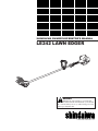 1
1
-
 2
2
-
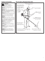 3
3
-
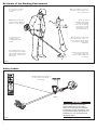 4
4
-
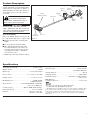 5
5
-
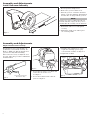 6
6
-
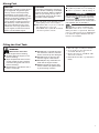 7
7
-
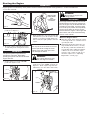 8
8
-
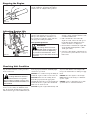 9
9
-
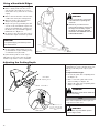 10
10
-
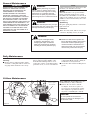 11
11
-
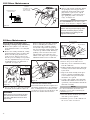 12
12
-
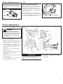 13
13
-
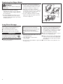 14
14
-
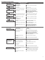 15
15
-
 16
16
-
 17
17
-
 18
18
-
 19
19
-
 20
20
-
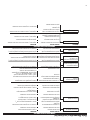 21
21
-
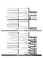 22
22
-
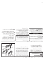 23
23
-
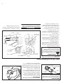 24
24
-
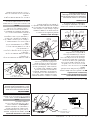 25
25
-
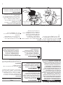 26
26
-
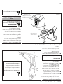 27
27
-
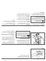 28
28
-
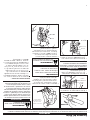 29
29
-
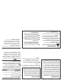 30
30
-
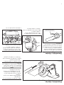 31
31
-
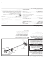 32
32
-
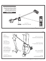 33
33
-
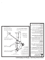 34
34
-
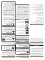 35
35
-
 36
36


Shindaiwa 81645 Manual de usuario
- Categoría
- Motor
- Tipo
- Manual de usuario
- Este manual también es adecuado para
en otros idiomas
- English: Shindaiwa 81645 User manual
Artículos relacionados
-
Shindaiwa 81604 Manual de usuario
-
-
-
-
-
-
-
-
-