
Istruzioni ed avvertenze per l’installazione e l’uso
Instructions and warnings for installation and use
Instrucciones y advertencias para su instalación y uso
Anleitungen und Hinweise zu Installation und Einsatz
Instruções e advertências para a instalação e utilização
Instructions et avertissements pour l’installation et l’usage
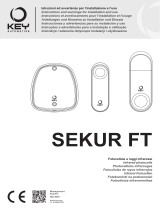
Motoriduttore interrato
Under grounded gear motor
Motoreducteur enterré
Motorreductor interrado
Unrterflur-Drehtorantrieb
Motorredutor interrado
Podziemny motoreduktor
UNDER
Istruzioni ed avvertenze per l’installazione e l’uso
Instructions and warnings for installation and use
Instrucciones y advertencias para su instalación y uso
Anleitungen und Hinweise zu Installation und Einsatz
Instruções e advertências para a instalação e utilização
Instructions et avertissements pour l’installation et l’usage
Management
System
ISO 9001:2008
www.tuv.com
ID 9105043769
LS22
Infrared photocells
Infrarot-Fotozellen
Fotocellule a raggi infrarossi
Photocellules infrarouges
Fotocélulas de rayos infrarrojos
Fotokomórki na podczerwień
Fotocélulas infravermelhas
3 - PRELIMINARY CHECKS
Before installing this product, verify and check the following steps:
• Make sure that the surface where the device is going to be secured is solid and does not
allow vibration
• Use electrical connections suitable for the electric requirements
• Verify that the power supply complies with the technical characteristics
4 - PRODUCT INSTALLATION
ASSEMBLY DESCRIPTION
• Prepare for the passing of the cables
• Open the cover of the photocells with the help of a screwdriver (Fig. 1)
• Secure the base to the wall using the screws provided (Fig. 2)
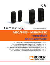
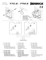
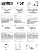
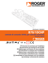
• Proceed with required wiring following Fig.3 (electric diagram for photocell connection
or following Fig.4 (electric diagram for couple of synchronized photocell connection)
• Check the alignment of transmitter and receiver making sure that led “L” of receiver
remains continuosly on (Fig. 5)
• Select the desired typology for OUT contact (J3)
• Mount the cover with the infrared screen
• Verify J3: Contact normally closed NC (by factory default) - Contact normally open NO
SYNCHRONIZATION: this function allows two pairs of photocells to operate in alter-
nation, in order to avoid interference between them. Synchronization is automatically
activated in the event of Vac power supply moving J2 to left (Fig 4)
"SNOW" FUNCTION: to achieve temporary adaptation to frequent jamming of the
photocell, the system activates automatic compensation: if the beam is interrupted for
more than 5 consecutive times, at a lower interval than 2 seconds, the beam must be
interrupted for 300 ms. in order to detect the obstacle. The normal mode is restored
automatically if no interruptions close to one another occur for 10 sec.
LOW RANGE: to avoid interference between the photocells and consequent insensi-
tivity to obstacles, due to the excessive proximity between them, remove the jumper to
lower the range from 25 m. to 8 m. (Fig.3)
5 - TESTING AND COMMISSIONING
The testing of the system must be performed by qualied technicians who must perform
the tests required by relevant legislation related to risks, ensuring compliance with the
provisions of the regulations, in particular the EN12445 standard, which species the
testing methods for the automation of doors and gates. Following the successful testing
of every (and not just some) device in the system, you can proceed with the commis-
sioning, following the instructions provided with the main product
6 - MORE INFORMATION
OPTIONAL DIAPHRAGM: in case of necessity, to reduce the cone of the receiver insert
the provided optional diaphragm into it (Fig. 6)
GB
1 - SAFETY WARNINGS
WARNING - for the safety of people,it is important to follow
these instructions and save them for future use.
Read the instructions carefully before starting installation. The design and manufacture
of the devices making up the product and the information contained in this manual com-
ply with safety regulations. However, wrong installation and programming may cause
serious physical injury to those who perform the work and those who will use the device.
For this reason, during installation, it is important to carefully follow all instructions in
this manual.
2- PRODUCT OVERVIEW
INFRARED PHOTOCELLS
The photocells of the FT series are safety devices applicable to the automation of doors
and gates, which allow to detect the presence of obstacles along the route between
transmitter and receiver.
Warning: any use other than the one described, and carried out under environ-
mental conditions other than the ones described in this manual, is to be consid-
ered improper and prohibited.
CODE DESCRIPTION
LS22 Pair of outdoor photocells (80x30x28mm).
TECHNICAL CHARACTERISTICS LS22
range 25 m / 8 m*
DEGREE OF PROTECTION IP54
Power supply
10/30Vac 10/40Vdc
rx consumption 27 mA
tx consumption 10 mA
relay contacts maximum current
1 A
relay contacts maximum voltage
24 Vdc
operating temperature -20° +55°C
* full power / weakened
MAIN COMPONENTS
• Opto-electronic circuit container • Anti-blinding diaphragm
• Opto-electronic circuit • Fixing screws
• Cover with infrared screen
D
1 - SICHERHEITSHINWEISE
ACHTUNG – Zur Personensicherheit ist es wichtig, diese Anleitungen zu beachten und sie für
den zukünftigen Gebrauch aufzubewahren.
Bevor Sie mit der Installation beginnen, lesen Sie die Bedienungsanleitung aufmerksam durch. Design und
Herstellung der Vorrichtungen, aus denen das Produkt besteht und die Informationen in diesem Handbuch
entsprechen den geltenden Sicherheitsvorschriften. Eine falsche Installation und Programmierung kann
jedoch zu schweren Verletzungen der Personen führen, die mit den Arbeiten beauftragt sind oder die An-
lage benutzen. Aus diesem Grund ist es wichtig, während der Installation genau den hier angegebenen
Anleitungen zu folgen.
2 - PRODUKTEINFÜHRUNG
INFRAROT-FOTOZELLEN
Die Fotozellen der Serie FT sind Sicherheitsvorkehrungen für automatisierte Türen und Tore, sie er-
möglichen das Erkennen eines Hindernisses entlang der Leitlinie zwischen Sender und Empfänger.
Achtung: jeder andere Gebrauch als der beschriebene sowie der Einsatz in abweichenden
Raumbedingungen, die nicht in dieser Gebrauchsanweisung enthalten sind, ist als unsach-
gemäß anzusehen und verboten.
ARTIKELNUMMER BESCHREIBUNG
LS22 Fotozellenpaar für Außenbereiche (80x30x28 mm).
TECHNISCHE MERKMALE
LS22
Leistung 25 m / 8 m*
Schutzgrad IP54
Versorgung 10/30Vac 10/40Vdc
RX Verbrauch 27 mA
TX Verbrauch 10 mA
Höchststrom Relaiskontakte 1 A
Höchstspannung Relaiskontakte 24 VDC
Betriebstemperatur -20° +55°C
* volle Leistung / gedrosselt
HAUPTKOMPONENTEN
• Gehäuse für optisch-elektronischen Schaltkreis • Lichtblende Blendschutz
• Optisch-elektronischer Schaltkreis • Befestigungsschrauben
• Abdeckung mit eingebautem Infrarotschirm
3 - VORPRÜFUNGEN
ACHTUNG - Vor der Installation folgende Punkte prüfen und kontrollieren:
• Prüfen, dass die Fläche, auf der die Vorrichtung befestigt werden soll, fest ist und keine Schwingungen überträgt.
• Für die erforderlichen Ströme geeignete Stromanschlüsse verwenden.
• Prüfen, dass die Versorgung den Werten der technischen Merkmale entspricht.
4 - PRODUKTINSTALLATION
MONTAGEBESCHREIBUNG
• den Kabeldurchzug vorbereiten
• Mit einem Schraubenzieher den Deckel der Fotozellen önen (Abb.1)
• Mit den beiliegenden Schrauben das Unterteil an der Wand befestigen (Abb. 2)
• Führen Sie nun die nötigen Anschlüsse gemäß Abb. 3 (Schaltplan Anschluss der Fotozellen) oder
Abb. 4 (Schaltplan Anschluss des synchronisierten Paars Fotozellen) durch.
• Überprüfen Sie die optimale Ausrichtung des Senders und Empfängers, indem Sie sich vergewissern,
dass die LED “L” des Empfängers ununterbrochen leuchtet (Abb. 5).
• Wählen Sie die gewünschte Art des Kontaktes OUT (J3).
• Montieren Sie die Abdeckung mit dem Infrarotschirm.
• Überprüfen Sie J3: Schließerkontakt NC (werkseitig) - Önerkontakt NO
SYNCHRONISMUS: mit dieser Funktion können zwei Fotozellenpaare im Wechsel arbeiten, dadurch
schließt man aus, dass sie sich gegenseitig stören. Der Synchronismus wird bei Versorgung mit VAC
automatisch aktiviert, indem J2 nach links umgelegt wird (Abb. 4).
FUNKTION “SCHNEE”: um eine vorübergehende Anpassung bei häugen Verdunkelungen der Foto-
zelle zu erzielen, aktiviert das System einen automatischen Ausgleich: wenn der Lichtstrahl in weniger als
2 Sek. mehr als 5-mal hintereinander unterbrochen wird, muss der Lichtstrahl zur Erkennung des Hinder-
nisses für 300 ms unterbrochen werden. Wenn für 10 Sek. keine aufeinanderfolgenden Unterbrechungen
auftrete, wird der Normalbetrieb automatisch wieder hergestellt.
KURZE REICHWEITE: damit sich die Fotozellen nicht gegenseitig stören und durch ihre zu starke An-
näherung nicht mehr auf das Hindernis reagieren, den Jumper entfernen, dadurch reduziert sich die
Reichweite von 250 m auf 8 m.
(Abb.3)
5 - TEST UND INBETRIEBNAHME
Die Endabnahme der Anlage muss von einem qualiziertem Techniker durchgeführt werden, der alle von
der entsprechenden Norm geforderten Proben bzgl. der bestehenden Risiken ausführen muss, insbeson-
dere entsprechend EN12445, welche die Testmethoden für Automationen von Türen und Tore enthält.
Nach der positiven Endabnahme aller (und nicht nur einiger) Vorrichtungen der Anlage, kann man gemäß
den Angaben in der Gebrauchsanleitung des Hauptprodukts die Inbetriebnahme vornehmen.
6 - ERLÄUTERUNGEN
OPTIONALE BLENDE: falls der Kegel des Empfängers reduziert werden muss, setzt man die bei-
liegende optionale Blende ein (Abb. 6)
F
1 - AVERTISSEMENTS POUR LA SÉCURITÉ
ATTENTION - pour la sécurité des personnes, il est important de respecter
ces instructions et de les conserver pour une utilisation future.
Lire attentivement les instructions avant de procéder à l’installation. La conception et la
fabrication des dispositifs composant le produit ainsi que les informations contenues dans le
présent manuel sont conformes aux normes de sécurité en vigueur. Cependant, une instal-
lation et une programmation erronées peuvent impliquer de graves blessures sur les per-
sonnes exécutant les travaux et sur les futurs utilisateurs. C'est pourquoi, durant l'installa-
tion, il est important de suivre attentivement toutes les instructions fournies dans ce manuel.
2 - INTRODUCTION AU PRODUIT
PHOTOCELLULES INFRAROUGES
Les photocellules de la série FT sont des dispositifs de sécurité applicables à l'automati-
sation de portes et portails, permettant de détecter la présence d'obstacles le long de la
trajectoire transmetteur/récepteur.
Attention : toute utilisation autre que celle décrite ici et dans des conditions environ-
nementales autres que celles indiquées dans ce manuel, doit être considérée comme
impropre et interdite.
CODE DESCRIPTION
LS22 Paire de photocellules pour extérieur (80x30x28mm).
CARACTÉRISTIQUES TECHNIQUES LS22
portée 25 m / 8 m*
degré de protection IP54
alimentation
10/30Vca 10/40Vcc
consommation rx 27 mA
consommation tx 10 mA
courant maximum des contacts de relais
1 A
tension maximum des contacts de relais
24 Vcc
température de fonctionnement
-20° +55°C
*pleine puissance / puissance aaiblie
PRINCIPAUX COMPOSANTS
• Conteneur circuit optico-électronique • Diaphragme anti-aveuglement
• Circuit optico-électronique • Vis de xation
• Couverture avec écran infrarouge incorporé
3 - VERIFICHE PRELIMINARI
ATTENZIONE – prima di installare il prodotto vericare e controllare i seguenti punti:
• Vericare che la supercie su cui ssare il dispositivo sia solida e non pemetta vibrazioni
• Utilizzare collegamenti elettrici adeguati alle correnti richieste
• Vericare che l’alimentazione rispetti i valori delle caratteristiche tecniche
4 - INSTALLAZIONE DEL PRODOTTO
DESCRIZIONE DI MONTAGGIO
• Predisporre l’arrivo dei cavi
• Aprire il coperchio delle fotocellule con l’aiuto di un cacciavite (Fig.1)
• Fissare la base al muro usando le apposite viti in dotazione (Fig. 2)
• Procedere ai collegamenti richiesti seguendo Fig.3 (Schema elettrico collegamento
FT) oppure Fig.4 (Schema elettrico collegamento coppia FT in sincronismo)
• Vericare l’allineamento ottimale del trasmettitore e del ricevitore accertandosi che il led
L del ricevitore rimanga acceso sso (Fig. 5)
• Selezionare la tipologia di contatto OUT voluta (J3)
• Montare il coperchio a schermo infrarosso
• Vericare J3:Contatto normalmente chiuso NC (di fabbrica) - Contatto normalmente aperto NO
SINCRONISMO: con questa funzione due coppie di fotocellule possono funzionare in
alternanza allo scopo di evitare interferenze tra di loro. Il sincronismo è attivato automati-
camente in caso di alimentazione Vac, spostando J2 a sinistra (Fig.4)
FUNZIONE “NEVE”: per ottenere un adattamento temporaneo a frequenti oscuramenti
della fotocellula il sistema attiva una compensazione automatica: se si vericano più di
5 interruzioni consecutive del fascio infrarosso a distanza minore di 2 sec l’una dall’altra,
il fascio deve essere interrotto per minimo 300 msec. per rilevare l’ostacolo. La modalità
normale si ripristina automaticamente se per 10 sec. non si vericano interruzioni ravvicinate.
BASSA PORTATA: per evitare l’interferenza tra le fotocellule e la conseguente insensibi-
lità all’ostacolo a causa dell’eccessiva vicinanza tra le medesime, togliere il jumper J1 per
ridurre la portata da 25 m. a 8 m. (Fig.3)
5 - COLLAUDO E MESSA IN SERVIZIO
Il collaudo dell’impianto va eseguito da un tecnico qualicato che deve eettuare le prove
richieste dalla normativa di riferimento in funzione dei rischi presenti, vericando il rispetto
di quanto previsto dalle normative, in particolare la norma EN12445 che indica i metodi di
prova per gli automatismi per porte e cancelli.
A seguito del positivo collaudo di tutti (e non solo di alcuni) i dispositivi dell’impianto si può
procedere con la messa in servizio, seguendo le indicazioni riportate nelle istruzioni del
prodotto principale
6 - APPROFONDIMENTI
DIAFRAMMA OPZIONALE: in caso di necessità per ridurre il campo di ricezione della
ricevente inserire nella stessa il diaframma opzionale in dotazione (Fig. 6)
I
1 - AVVERTENZE PER LA SICUREZZA
ATTENZIONE – per la sicurezza delle persone è importante rispettare
queste istruzioni e conservarle per utilizzi futuri.
Leggere attentamente le istruzioni prima di eseguire l’installazione. La progettazione e la
fabbricazione dei dispositivi che compongono il prodotto e le informazioni contenute nel
presente manuale rispettano le normative vigenti sulla sicurezza. Ciò nonostante un’in-
stallazione e una programmazione errata possono causare gravi ferite alle persone che
eseguono il lavoro e a quelle che useranno l’impianto. Per questo motivo, durante l’instal-
lazione, è importante seguire attentamente tutte le istruzioni riportate in questo manuale.
2 - INTRODUZIONE AL PRODOTTO
FOTOCELLULE A RAGGI INFRAROSSI
Le fotocellule della serie FT sono dei dispositivi di sicurezza applicabili all’automazione
di porte e cancelli che permettono di rilevare la presenza di ostacoli lungo la direttrice tra
trasmettitore e ricevitore.
Attenzione: qualsiasi altro uso diverso da quello descritto e in condizioni ambien-
tali diverse da quelle riportate in questo manuale è da considerarsi improprio e
vietato.
CODICE DESCRIZIONE
LS22 Coppia di fotocellule da esterno (80x30x28mm).
CARATTERISTICHE TECNICHE LS22
portata 25 m / 8 m*
grado di protezione IP54
alimentazione 10/30Vac 10/40Vdc
consumo rx 27 mA
consumo tx 10 mA
corrente max contatti relais 1 A
tensione max contatti relais 24 Vdc
temperatura di funzionamento -20° +55°C
* piena potenza / depotenziato
PRINCIPALI COMPONENTI
• Contenitore circuito ottico-elettronico • Diaframma anti accecamento
• Circuito ottico-elettronico • Viti di ssaggio
• Copertura con schermo infrarosso incorporato
3 - CONTRÔLES PRÉLIMINAIRES
ATTENTION - avant d'installer le produit, vérier les points suivants :
• Vérier que la surface sur laquelle le dispositif sera xé soit solide et imperméables aux vibrations.
• Utiliser des branchements électriques adaptés aux exigences actuelles.
• Vérier que l'alimentation soit conforme aux valeurs des caractéristiques techniques.
4 - INSTALLATION DU PRODUIT
DESCRIPTION DU MONTAGE
• Préparer l'arrivée des câbles.
• Ouvrir le couvercle des photocellules à l'aide d'un tournevis (Fig.1).
• Fixer la base au mur en utilisant les vis fournies (Fig. 2).
• Eectuer les raccordements nécessaires en suivant les indications de la Fig. 3 (Schéma
électrique de branchement FT) ou de la Fig. 4 (Schéma électrique de branchement
du couple FT en synchronisme)
• Vérier que l’alignement de l’émetteur et du récepteur est optimal en s’assurant que la
DEL du récepteur reste allumée xement (Fig. 5)
• Sélectionner le type de contact de SORTIE voulu (J3)
• Monter le couvercle à écran infrarouge
• Vérier J3 : contact normalement fermé NF (d’usine) - Contact normalement ouvert NO
SYNCHRONISATION : cette fonction permet le fonctionnement en alternance de deux
paires de photocellules, an d'éviter toute interférence entre elles. Le synchronisme est
automatiquement activé en cas d’alimentation Vca, en déplaçant J2 à gauche (Fig. 4).
FONCTION « NEIGE » : pour obtenir une adaptation temporaire à des blocages fréquents de
la cellule photo-électrique, le système active une compensation automatique : en présence de
plus de 5 interruptions consécutives du faisceau en moins de 2 secondes, le faisceau devra
être interrompu pendant 300 ms pour procéder à la détection de l'obstacle. Le mode normal
est automatiquement rétabli en absence d'interruptions rapprochées pendant 10 secondes.
FAIBLE PORTÉE : an d'éviter les interférences entre les cellules photoélectriques et la
conséquente insensibilité à l'obstacle en raison de leur proximité excessive, retirer le jumper
pour réduire la portée de 25 m. à 8 m. (Fig.3)
5 - ESSAI ET MISE EN SERVICE
L'essai du système doit être eectué par un technicien qualié. Celui-ci procèdera aux essais
requis par la norme relative en fonction des risques présents, et vériera l'adéquation aux
prescriptions normatives, en particulier celles de la norme EN12445 indiquant les méthodes
d'essai pour les automatismes relatifs aux portes et portails. Si tous les dispositifs (et pas
seulement certains d'entre eux) passent les tests avec succès, le système pourra être mis
en service, conformément aux indications fournies dans les instructions du produit principal.
6 - APPROFONDISSEMENTS
DIAPHRAGME EN OPTION : en cas de nécessité de réduire le cône du récepteur, insérer
le diaphragme en option fourni en dotation à l'intérieur du récepteur (Fig. 6).

Meucci23
7San Donà
154.000
'azienda
The undersigned Nicola Michelin, General Manager of the company:
S...Meucci237San Donà
declares that the product type:
LS
Infrared photocells with RX-TX module
Models:
LS
Is in conformity with the following community (EC) regulations:
In accordance with the following harmonized standards regulations:
San Donà
General Manager
RX1
12/24 Vac
~
DOUBLE FT CONNECTIONS WITH SYNCHRONISM
“only Vac”
Control
Unit
FT1/FT2
COM
TX1
COM
OUT
RX2
RX
Control
Unit
FT1/FT2
COM
TX2
COM
OUT
~
GND
_
GND
_
GND
_
GND
_
SYNCRONISM = J2
1
2
3
5 6
4
12/24
AC/DC
12/24
AC/DC
12/24
AC/DC
12/24
AC/DC
L
L
J1
NC
NO
HI
J1
NC
NO
HI
J3
J3
FT1
FT2
TX1
RX1
TX2
FT2
RX2
FT2
4b
FT1 FT1
J2
J2
SINGLE FT
CONNECTIONS
RX
12/24 Vac/dc
Control
Unit
FT1/FT2
COM
TX
GND
_
12/24
AC/DC
GND
_
25 m =
8 m =
12/24
AC/DC
COM
OUT
NC
L
NO
GND/-
HI
J1
J3
J2
SYNCRONISM = J2
RX1
12/24 Vac
~
DOUBLE FT CONNECTIONS WITH SYNCHRONISM
“only Vac”
Control
Unit
FT1/FT2
COM
TX1
COM
OUT
RX2
RX
Control
Unit
FT1/FT2
COM
TX2
COM
OUT
~
GND
_
GND
_
GND
_
GND
_
SYNCRONISM = J2
1
2
3
5 6
4
12/24
AC/DC
12/24
AC/DC
12/24
AC/DC
12/24
AC/DC
L
L
J1
NC
NO
HI
J1
NC
NO
HI
J3
J3
FT1
FT2
TX1
RX1
TX2
FT2
RX2
FT2
4b
FT1 FT1
J2
J2
SINGLE FT
CONNECTIONS
RX
12/24 Vac/dc
Control
Unit
FT1/FT2
COM
TX
GND
_
12/24
AC/DC
GND
_
25 m =
8 m =
12/24
AC/DC
COM
OUT
NC
L
NO
GND/-
HI
J1
J3
J2
SYNCRONISM = J2
Meucci23
7San Donà
154.000
'azienda
The undersigned Nicola Michelin, General Manager of the company:
S...Meucci237San Donà
declares that the product type:
LS
Infrared photocells with RX-TX module
Models:
LS
Is in conformity with the following community (EC) regulations:
In accordance with the following harmonized standards regulations:
San Donà
General Manager
PT
1 - ADVERTÊNCIAS PARA A SEGURANÇA
ATENÇÃO - para a segurança das pessoas é importante respeitar estas instru-
ções e guarde-as para uso futuro.
Leia com atenção as instruções antes de executar a instalação. A concepção e a pro-
dução dos dispositivos que compõem o produto e as informações contidas no presente
manual respeitam as normas vigentes sobre a segurança. Não obstante, uma instala-
ção e programação erradas podem causar graves ferimentos às pessoas que execu-
tam o trabalho e às pessoas que utilizarão o sistema. Por este motivo, durante a ins-
talação, é importante seguir atentamente todas as instruções indicadas neste manual.
2 - INTRODUÇÃO AO PRODUTO
Fotocélulas infravermelhas
As fotocélulas da série FT são dispositivos de segurança que são utilizados na automa-
tização de portas e portões, e permitem detectar a presença de obstáculos ao longo do
percurso entre o emissor e o receptor.
Aviso: qualquer uso que não seja descrito e em condições ambientais diferentes
daquelas descritas neste manual deve ser considerado impróprio e proibido.
CÓDIGO DESCRIÇÃO
LS22 Par de fotocélulas externas (80x30x28mm).
CARACTERÍSTICAS TÉCNICAS
LS22
capacidade
25 m / 8 m*
Grau de proteção
Ip54
Alimentação
10/30Vac 10/40Vdc
consumo rx
27 mA
consumo tx
10 mA
corrente máx contatos do relé
1 A
voltagem máx contatos do relé
24 VDC
temperatura de funcionamento
-20° + 55°C
* potência total/sem potência
PRINCIPAIS COMPONENTES
• Quadro circuito óptico-electrónico • Diafragma anti-ofuscamento
• Circuito óptico-electrónico • Parafusos de xação
• Cubra com tela infravermelho incorporada
3 - KONTROLE WSTĘPNE
UWAGA - przed instalacją produktu sprawdzić i skontrolować następujące punkty:
• Sprawdzić, czy powierzchnia na której będzie montowane urządzenie jest solidna i nie powoduje wibracji
• Użyć podłączeń elektrycznych adekwatnych do wymagań prądu
• Sprawdzić czy zasilanie jest zgodne z wartościami danych technicznych
4 - INSTALACJA PRODUKTU
OPIS MONTAŻU
• Przygotować miejsce montażu przewodów
• Otworzyć obudowę fotokomórek za pomocą śrubokrętu (Rys.1)
• Przymocować podstawę do ściany, używając odpowiednich śrub zawartych w zestawie (Rys. 2)
• Podłączaj przewody zgodnie z zaleceniami zawartymi w punkcie 3.(schemat połączeń elektrycznych
dla fotokomórek) albo zgodnie z punktem 4.(schemat połączeń elektrycznych dla pary
zsynchronizowanych fotokomórek)
• Sprawdź ustawienia nadajnika i odbiornika upewniając się, że dioda LED na odbiorniku stale świeci (Rys.5)
• Wybierz żądany typ wyjścia (J3)
• Zamontuj pokrywę fotokomórki
• Zwerykuj: styk normalnie zamknięty NC (wg. ustawień fabrycznych) - styk normalnie otwarty NO
SYNCHRONIZACJA: dzięki tej funkcji obie pary komórek mogą działać na przemian, w celu uniknięcia
interferencji między nimi. Synchronizacja jest uaktywniona automatycznie w przypadku obwodu zasilania
J2 w lewym kierunku (Rys.4)
FUNKCJA “REKOMPENSATA ŚNIEGU”: w celu chwilowego dostosowania fotokomórki do częstych
zasłonięć, system aktywuje automatyczną rekompensatę: jeśli dojdzie do conajmniej pięciokrotnego prze-
rwania wiązki w odstępie czasu krótszym niż 2 sek., wiązka musi zostać przerwana na 300 ms. w celu
wykrycia przeszkody. Normalny tryb pracy zostaje ponownie ustawiony, jeśli w czasie 10 sek. nie dojdzie
do przerw w pracy
NISKI ZASIĘG: w celu uniknięcia interferencji między fotokomórkami i co się z tym wiąże niezdolności do
wykrycia przeszkody z powodu zbytniego przybliżenia między nimi, należy usunąć zworkę, aby zmniejszyć
zasięg z 25 m. na 8 m.
(
Rys.
3)
5 - PRÓBA TECHNICZNA I URUCHOMIENIE
Procedura testowania instalacji musi być przeprowadzona przez wykwalikowanego technika, który musi
przeprowadzić przewidziane próby mające na celu określenie obecności ryzyka i określić zgodność in-
stalacji z obowiązującymi normami, a szczególnie z postanowieniami EN 12445, która określa metody
testów dla systemów automatyki drzwi i bram. Po uzyskaniu pozytywnego wyniku procedury testowania
wszystkich (a nie tylko niektórych) urządzeń instalacji można rozpocząć uruchomienie, postępując zgodnie
ze wskazówkami umieszczonymi w instrukcji głównego produktu
6 - UZUPEŁNIENIA
OSŁONA OPCJONALNA: jeśli zajdzie konieczność zredukowania pola zasięgu odbiornika należy umie-
ścić osłonę opcjonalną znajdującą się w zestawie (Rys. 6)
3 - COMPROBACIONES PRELIMINARES
ATENCIÓN - Antes de instalar el producto compruebe y controle los siguientes puntos:
• Controlar que la supercie en la que se ja el dispositivo sea sólida y no permita vibraciones
• Utilizar conexiones eléctricas adecuadas a las corrientes requeridas
• Controlar que la alimentación respete los valores de las características técnicas
4 - INSTALACIÓN DEL PRODUCTO
DESCRIPCIÓN DEL MONTAJE
• Preparar la llegada de los cables
• Abrir la tapadera de las fotocélulas con la ayuda de un destornillados (Fig.1)
• Fijar la base a la pared utilizando los tornillos adecuados que se encuentran en el
suministro (Fig. 2)
• Proceder con las conexiones necesarias siguiendo Fig.3 (esquema eléctrico conexión
FT) o Fig.4 (esquema eléctrico conexión pareja FT sincronizadas)
• Vericar alineación óptima del emisor y del receptor comprovando que el led L del
receptor permanezca encendido jo (Fig.5)
• Seleccionar la tipología de contacto OUT deseada (J3)
• Montar la tapa con pantalla infrarroja
• Vericar J3: Contacto normalmente cerrado NC (de fábrica) - Contacto normalmente abierto NO
SINCRONISMO: con esta función dos parejas de fotocélulas pueden funcionar alterna-
tivamente con el objetivo de evitar interferencias entre sí. El sincronismo está activado
automaticamente en caso de alimentación Vac, desplazando J2 a izquierdas (Fig.4)
FUNCIÓN “NIEVE”: para lograr una adaptación temporal con frecuentes oscurecimien-
tos de la fotocélula el sistema activa una compensación automática: si ocurren más de 5
interrupciones consecutivas del haz a una distancia menor de 2 seg. el haz debe interru-
mpirse por 300 msec. para detectar el obstáculo. La modalidad normal se restablece en
automático si durante 10 seg. no ocurren interrupciones cercanas.
BAJA CAPACIDAD: para evitar la interferencia entre las fotocélulas y la consecuente in-
sensibilidad con respecto al obstáculo por la excesiva cercanía entre ambos, quitar el jum-
per para reducir la capacidad de 25 m. a 8 m. (Fig.3)
5 - ENSAYO Y PUESTA EN SERVICIO DE LA AUTOMATIZACIÓN
El ensayo de la instalación debe realizarlo un técnico calicado el cual deberá llevar a cabo las
pruebas requeridas por la normativa de referencia en función de los riesgos presentes, com-
probando el respeto de cuanto prevén las normativas, especialmente la EN12445, que indica
los métodos de prueba para las automatizaciones de puertas y cancelas. Tras el éxito positivo
de la prueba de todos (y no sólo de algunos) los dispositivos de la instalación se puede seguir
con la puesta en servicio, siguiendo las indicaciones que se encuentan en el producto principal
6 - PROFUNDIZACIONES
DIAFRAGMA OPCIONAL: en caso de necesidad para reducir el cono del receptor insertar
en él el diafragma opcional suministrado (Fig. 6)
PL
1 - ZALECENIA DOTYCZĄCE BEZPIECZEŃSTWA
UWAGA – dla bezpieczeństwa osób należy przestrzegać tych instrukcji i zachować je do wykorzy-
stania w przyszłości.
Przed rozpoczęciem instalacji należy dokładnie przeczytać instrukcję. Projektowanie i produkcja urządzeń
wchodzących w skład produktu oraz informacje zawarte w niniejszej instrukcji odpowiadają obecnie obo-
wiązującym przepisom dotyczącym bezpieczeństwa. Pomimo tego, błędna instalacja i błędne programo-
wanie mogą skutkować poważnymi obrażeniami osób, które wykonują pracę oraz tych, które będą używać
instalacji. Dlatego też, w trakcie instalacji, ważnym jest, aby postępować zgodnie z wszystkimi instrukcjami
znajdującymi się w tym podręczniku.
2 - WPROWADZENIE DO PRODUKTU
FOTOKOMÓRKI NA PODCZERWIEŃ
Fotokomórki z serii FT to urządzenia bezpieczeństwa stosowane w automatyce drzwi i bram pozwalających
wykryć obecność przeszkód wzdłuż linii działania pomiędzy nadajnikiem a odbiornikiem.
Uwaga: każde inne użycie odmienne od tego opisanego i w warunkach odmiennych od tych okre-
ślonych w niniejszej instrukcji należy uznać za niewłaściwe i zabronione.
KOD OPIS
LS22 Para fotokomórek zewnętrznych (80x30x28mm).
DANE TECHNICZNE
LS22
zasięg
25 m / 8 m*
stopień ochrony
IP54
zasilanie
10/30Vac 10/40Vdc
pobór prądu rx
27 mA
pobór prądu tx
10 mA
maks.zasilanie styków przekaźnika
1 A
maks.napięcie styków przekaźnika
24 Vdc
temperatura pracy
-20° +55°C
* pełna moc / moc ograniczona
GŁÓWNE KOMPONENTY
• Obudowa obwodu optyczno-elektronicznego • Osłona przeciwoślepieniowa
• Obwód optyczno-elektroniczny • Śruby mocujące
• Pokrywa z wbudowanym ekranem na podczerwień
E
1 - ADVERTENCIAS DE SEGURIDAD
ATENCIÓN – para la seguridad de las personas hay que respetar
estas instrucciones y conservarlas para usos futuros.
Lea las instrucciones detenidamente antes de efectuar la instalación. La proyectación y la
fabricación de los dispositivos que componen el producto, así como la información que con-
tiene esta manual respetan las normativas vigentes sobre seguridad. No obstante esto, una
instalación y una programación erróneas podrían causar heridas graves tanto a las perso-
nas que realizan el trabajo como a las que utilizarán la instalación. Por este motivo, durante
la instalación, es importante seguir atentamente todas las instrucciones de este manual.
2 - INTRODUCCIÓN AL PRODUCTO
FOTOCÉLULAS DE RAYOS INFRARROJOS
Las fotocélulas de la serie FT son dispositivos de seguridad que se aplican a la automación
de puertas y cancelas que permiten detectar la presencia de posibles obstáculos en el
espacio entre el transmisor y el receptor.
Atención: cualquier otro uso distinto de lo que se describe y en condiciones ambien-
tales diferentes con respecto a lo que se encuentra en este manual ha de conside-
rarse impropio y prohibido.
CÓDIGO DESCRIPCIÓN
LS22 Par de fotocélulas para exteriores (80x30x28 mm).
CARACTERÍSTICAS TÉCNICAS LS22
capacidad / 25 m / 8 m*
grado de protección IP54
alimentación
10/30Vac 10/40Vdc
consumo rx 27 mA
consumo tx 10 mA
corriente máx. contactos relés
1 A
tensión máx. contactos relés 24 Vdc
temperatura de funcionamiento
-20° + 55°C
* potencia llena / debilitado
COMPONENTES PRINCIPALES
• Caja del circuito óptico-electrónico • Diafragma anti ceguedad
• Circuito optico-electrónico • Tornillo de jación
• Cubierta con pantalla infrarroja incorporada
3 - VERIFICAÇÕES PRELIMINARES
ATENÇÃO - Antes de instalar o produto, verique e controle os seguintes pontos:
• Certique-se de que a superfície em que você pode conectar o dispositivo é sólido e não permite vibrações
• Use conexões eléctricas adaptadas às necessidades actuais
• Verique que a fonte de alimentação está em conformidade com os valores das
características técnicas
4 - INSTALAÇÃO DO PRODUTO
Descrição da montagem
• Prepare-se para a chegada dos cabos
• Abra a tampa das fotocélulas com a ajuda de uma chave de fenda (Fig.1)
• Fixe a base para a parede usando os parafusos fornecidos(Fig. 2)
• Prosseguir com as ligações necessárias seguintes Fig.3 (esquema elétrico ligação
FT) ou Fig.4 (esquema elétrico ligação parelha FT sincronizadas)
• Vericar o correto alinhamento do emissor face ao recetor comprovando que o LED L
do recetor esteja aceso xo (Fig. 5)
• Selecione o tipo de contato desejado OUT (J3)
• Montar a tampa de infravermelho
• Verique J3: Contacto normalmente fechado NC (de fábrica) – Contacto normalmente
aberto NO
SINCRONISMO: esta função com dois pares de fotocélulas pode operar em alternân-
cia, a m de evitar a interferência entre elas. O sincronismo está ativo automaticamente
no caso de a alimentação ser Vac, movendo J2 para a esquerda (Fig. 4)
FUNÇÃO “NEVE”: para obter uma adaptação temporária a a freqüente interferências,
o sistema activa uma compensação automática: Se você tem mais de cinco interrup-
ções consecutivas do feixe a uma distância de menos de 2 segundos. o feixe tem de
ser interrompido por 300 msec. para detectar o obstáculo. O modo normal é restaurado
automaticamente se por10 sec. não ocorrem interrupções.
BAIXA CAPACIDADE: a m de evitar a interferência entre as células fotoeléctricas e
A consequente insensibilidade ao obstáculo devido à proximidade excessiva entre os
mesmos, reduzA a taxa de uxo a partir de 25 m. a 8 m. (Fig.3)
5 - TESTE E COLOCAÇÃO EM SERVIÇO DA MÁQUINA
O teste do sistema deve ser executado por um técnico qualicado que deve efectuar os testes
solicitados pela normativa de referência em função dos riscos presentes, vericando o cumpri-
mento das disposições previstas pelas normativas, em particular a norma EN12445 que indica
os métodos de teste a máquinas para portas e portões. Após o teste bem sucedido de todos (e
não apenas alguns) dispositivos do sistema, você pode prosseguir com a operação, seguindo as
instruções dadas no manual de instrucções do produto principal
6 - MAIORES INFORMAÇÕES
DIAFRAGMA OPCIONAL: em caso de necessidade de reduzir o cone do receptor,
insira na mesma membrana fornecida (Fig. 6)
580ISFT22W rev.01
Transcripción de documentos
Instructions and warnings for installation and use Anleitungen und Hinweise zu Installation und Einsatz Istruzioni ed avvertenze per l’installazione e l’uso Instructions et avertissements pour l’installation et l’usage Instrucciones y advertencias para su instalación y uso Instruções e advertências para a instalação e utilização GB 1 - SAFETY WARNINGS 3 - PRELIMINARY CHECKS WARNING - for the safety of people,it is important to follow these instructions and save them for future use. Before installing this product, verify and check the following steps: • Make sure that the surface where the device is going to be secured is solid and does not allow vibration • Use electrical connections suitable for the electric requirements • Verify that the power supply complies with the technical characteristics Read the instructions carefully before starting installation. The design and manufacture of the devices making up the product and the information contained in this manual comply with safety regulations. However, wrong installation and programming may cause serious physical injury to those who perform the work and those who will use the device. For this reason, during installation, it is important to carefully follow all instructions in this manual. 2- PRODUCT OVERVIEW INFRARED PHOTOCELLS The photocells of the FT series are safety devices applicable to the automation of doors and gates, which allow to detect the presence of obstacles along the route between transmitter and receiver. Warning: any use other than the one described, and carried out under environmental conditions other than the ones described in this manual, is to be considered improper and prohibited. CODE DESCRIPTION LS22 Pair of outdoor photocells (80x30x28mm). TECHNICAL CHARACTERISTICS range LS22 25 m / 8 m* 4 - PRODUCT INSTALLATION ASSEMBLY DESCRIPTION • Prepare for the passing of the cables • Open the cover of the photocells with the help of a screwdriver (Fig. 1) • Secure the base to the wall using the screws provided (Fig. 2) • Proceed with required wiring following Fig.3 (electric diagram for photocell connection or following Fig.4 (electric diagram for couple of synchronized photocell connection) • Check the alignment of transmitter and receiver making sure that led “L” of receiver remains continuosly on (Fig. 5) • Select the desired typology for OUT contact (J3) • Mount the cover with the infrared screen • Verify J3: Contact normally closed NC (by factory default) - Contact normally open NO SYNCHRONIZATION: this function allows two pairs of photocells to operate in alternation, in order to avoid interference between them. Synchronization is automatically activated in the event of Vac power supply moving J2 to left (Fig 4) "SNOW" FUNCTION: to achieve temporary adaptation to frequent jamming of the photocell, the system activates automatic compensation: if the beam is interrupted for more than 5 consecutive times, at a lower interval than 2 seconds, the beam must be interrupted for 300 ms. in order to detect the obstacle. The normal mode is restored automatically if no interruptions close to one another occur for 10 sec. DEGREE OF PROTECTION IP54 Power supply 10/30Vac 10/40Vdc rx consumption 27 mA tx consumption 10 mA relay contacts maximum current 1A relay contacts maximum voltage 24 Vdc 5 - TESTING AND COMMISSIONING operating temperature -20° +55°C The testing of the system must be performed by qualified technicians who must perform the tests required by relevant legislation related to risks, ensuring compliance with the provisions of the regulations, in particular the EN12445 standard, which specifies the testing methods for the automation of doors and gates. Following the successful testing of every (and not just some) device in the system, you can proceed with the commissioning, following the instructions provided with the main product UNDER LOW RANGE: to avoid interference between the photocells and consequent insensitivity to obstacles, due to the excessive proximity between them, remove the jumper to lower the range from 25 m. to 8 m. (Fig.3) * full power / weakened MAIN COMPONENTS • Opto-electronic circuit container • Opto-electronic circuit • Cover with infrared screen Istruzioni ed avvertenze per l’installazione e l’uso Instructions and warnings for installation and use Instructions et avertissements pour l’installation et l’usage Instrucciones y advertencias para su instalación y uso Anleitungen und Hinweise zu Installation und Einsatz Instruções e advertências para a instalação e utilização • Anti-blinding diaphragm • Fixing screws LS22 Motoriduttore interrato Under grounded gear motor Motoreducteur enterré Motorreductor interrado Unrterflur-Drehtorantrieb Motorredutor interrado Podziemny motoreduktor 6 - MORE INFORMATION Management System ISO 9001:2008 OPTIONAL DIAPHRAGM: in case of necessity, to reduce the cone of the receiver insert the provided optional diaphragm into it (Fig. 6) D Infrared photocells Infrarot-Fotozellen Fotocellule a raggi infrarossi Photocellules infrarouges Fotocélulas de rayos infrarrojos Fotokomórki na podczerwień Fotocélulas infravermelhas www.tuv.com ID 9105043769 I 1 - SICHERHEITSHINWEISE 3 - VORPRÜFUNGEN 1 - AVVERTENZE PER LA SICUREZZA ACHTUNG – Zur Personensicherheit ist es wichtig, diese Anleitungen zu beachten und sie für den zukünftigen Gebrauch aufzubewahren. ACHTUNG - Vor der Installation folgende Punkte prüfen und kontrollieren: •Prüfen,dassdieFläche,aufderdieVorrichtungbefestigtwerdensoll,festistundkeineSchwingungenüberträgt. • Für die erforderlichen Ströme geeignete Stromanschlüsse verwenden. • Prüfen, dass die Versorgung den Werten der technischen Merkmale entspricht. ATTENZIONE – per la sicurezza delle persone è importante rispettare queste istruzioni e conservarle per utilizzi futuri. Bevor Sie mit der Installation beginnen, lesen Sie die Bedienungsanleitung aufmerksam durch. Design und Herstellung der Vorrichtungen, aus denen das Produkt besteht und die Informationen in diesem Handbuch entsprechen den geltenden Sicherheitsvorschriften. Eine falsche Installation und Programmierung kann jedoch zu schweren Verletzungen der Personen führen, die mit den Arbeiten beauftragt sind oder die Anlage benutzen. Aus diesem Grund ist es wichtig, während der Installation genau den hier angegebenen Anleitungen zu folgen. 2 - PRODUKTEINFÜHRUNG INFRAROT-FOTOZELLEN Die Fotozellen der Serie FT sind Sicherheitsvorkehrungen für automatisierte Türen und Tore, sie ermöglichen das Erkennen eines Hindernisses entlang der Leitlinie zwischen Sender und Empfänger. Achtung: jeder andere Gebrauch als der beschriebene sowie der Einsatz in abweichenden Raumbedingungen, die nicht in dieser Gebrauchsanweisung enthalten sind, ist als unsachgemäß anzusehen und verboten. ARTIKELNUMMER BESCHREIBUNG LS22 Fotozellenpaar für Außenbereiche (80x30x28 mm). TECHNISCHE MERKMALE Leistung LS22 25 m / 8 m* Schutzgrad IP54 Versorgung 10/30Vac 10/40Vdc RX Verbrauch 27 mA TX Verbrauch 10 mA Höchststrom Relaiskontakte 1A Höchstspannung Relaiskontakte 24 VDC Betriebstemperatur -20° +55°C * volle Leistung / gedrosselt HAUPTKOMPONENTEN • Gehäuse für optisch-elektronischen Schaltkreis • Optisch-elektronischer Schaltkreis • Abdeckung mit eingebautem Infrarotschirm • Lichtblende Blendschutz • Befestigungsschrauben 4 - PRODUKTINSTALLATION MONTAGEBESCHREIBUNG • den Kabeldurchzug vorbereiten • Mit einem Schraubenzieher den Deckel der Fotozellen öffnen (Abb.1) • Mit den beiliegenden Schrauben das Unterteil an der Wand befestigen (Abb. 2) • Führen Sie nun die nötigen Anschlüsse gemäß Abb. 3 (Schaltplan Anschluss der Fotozellen) oder Abb. 4 (Schaltplan Anschluss des synchronisierten Paars Fotozellen) durch. • Überprüfen Sie die optimale Ausrichtung des Senders und Empfängers, indem Sie sich vergewissern, dass die LED “L” des Empfängers ununterbrochen leuchtet (Abb. 5). • Wählen Sie die gewünschte Art des Kontaktes OUT (J3). • Montieren Sie die Abdeckung mit dem Infrarotschirm. • Überprüfen Sie J3: Schließerkontakt NC (werkseitig) - Öffnerkontakt NO SYNCHRONISMUS: mit dieser Funktion können zwei Fotozellenpaare im Wechsel arbeiten, dadurch schließt man aus, dass sie sich gegenseitig stören. Der Synchronismus wird bei Versorgung mit VAC automatisch aktiviert, indem J2 nach links umgelegt wird (Abb. 4). FUNKTION “SCHNEE”: um eine vorübergehende Anpassung bei häufigen Verdunkelungen der Fotozelle zu erzielen, aktiviert das System einen automatischen Ausgleich: wenn der Lichtstrahl in weniger als 2 Sek. mehr als 5-mal hintereinander unterbrochen wird, muss der Lichtstrahl zur Erkennung des Hindernisses für 300 ms unterbrochen werden. Wenn für 10 Sek. keine aufeinanderfolgenden Unterbrechungen auftrete, wird der Normalbetrieb automatisch wieder hergestellt. Leggere attentamente le istruzioni prima di eseguire l’installazione. La progettazione e la fabbricazione dei dispositivi che compongono il prodotto e le informazioni contenute nel presente manuale rispettano le normative vigenti sulla sicurezza. Ciò nonostante un’installazione e una programmazione errata possono causare gravi ferite alle persone che eseguono il lavoro e a quelle che useranno l’impianto. Per questo motivo, durante l’installazione, è importante seguire attentamente tutte le istruzioni riportate in questo manuale. 2 - INTRODUZIONE AL PRODOTTO FOTOCELLULE A RAGGI INFRAROSSI Le fotocellule della serie FT sono dei dispositivi di sicurezza applicabili all’automazione di porte e cancelli che permettono di rilevare la presenza di ostacoli lungo la direttrice tra trasmettitore e ricevitore. Attenzione: qualsiasi altro uso diverso da quello descritto e in condizioni ambientali diverse da quelle riportate in questo manuale è da considerarsi improprio e vietato. CODICE DESCRIZIONE LS22 Coppia di fotocellule da esterno (80x30x28mm). CARATTERISTICHE TECNICHE portata LS22 25 m / 8 m* grado di protezione IP54 alimentazione 10/30Vac 10/40Vdc consumo rx 27 mA 5 - TEST UND INBETRIEBNAHME consumo tx 10 mA corrente max contatti relais 1A Die Endabnahme der Anlage muss von einem qualifiziertem Techniker durchgeführt werden, der alle von der entsprechenden Norm geforderten Proben bzgl. der bestehenden Risiken ausführen muss, insbesondere entsprechend EN12445, welche die Testmethoden für Automationen von Türen und Tore enthält. Nach der positiven Endabnahme aller (und nicht nur einiger) Vorrichtungen der Anlage, kann man gemäß den Angaben in der Gebrauchsanleitung des Hauptprodukts die Inbetriebnahme vornehmen. tensione max contatti relais 24 Vdc temperatura di funzionamento -20° +55°C 6 - ERLÄUTERUNGEN • Contenitore circuito ottico-elettronico • Circuito ottico-elettronico • Copertura con schermo infrarosso incorporato KURZE REICHWEITE: damit sich die Fotozellen nicht gegenseitig stören und durch ihre zu starke Annäherung nicht mehr auf das Hindernis reagieren, den Jumper entfernen, dadurch reduziert sich die Reichweite von 250 m auf 8 m. (Abb.3) OPTIONALE BLENDE: falls der Kegel des Empfängers reduziert werden muss, setzt man die beiliegende optionale Blende ein (Abb. 6) * piena potenza / depotenziato PRINCIPALI COMPONENTI • Diaframma anti accecamento • Viti di fissaggio F 3 - VERIFICHE PRELIMINARI 1 - AVERTISSEMENTS POUR LA SÉCURITÉ 3 - CONTRÔLES PRÉLIMINAIRES ATTENZIONE – prima di installare il prodotto verificare e controllare i seguenti punti: • Verificare che la superficie su cui fissare il dispositivo sia solida e non pemetta vibrazioni • Utilizzare collegamenti elettrici adeguati alle correnti richieste • Verificare che l’alimentazione rispetti i valori delle caratteristiche tecniche ATTENTION - pour la sécurité des personnes, il est important de respecter ces instructions et de les conserver pour une utilisation future. ATTENTION - avant d'installer le produit, vérifier les points suivants : •Vérifierquelasurfacesurlaquelleledispositifserafixésoitsolideetimperméablesauxvibrations. • Utiliser des branchements électriques adaptés aux exigences actuelles. • Vérifier que l'alimentation soit conforme aux valeurs des caractéristiques techniques. 4 - INSTALLAZIONE DEL PRODOTTO DESCRIZIONE DI MONTAGGIO • Predisporre l’arrivo dei cavi • Aprire il coperchio delle fotocellule con l’aiuto di un cacciavite (Fig.1) • Fissare la base al muro usando le apposite viti in dotazione (Fig. 2) • Procedere ai collegamenti richiesti seguendo Fig.3 (Schema elettrico collegamento FT) oppure Fig.4 (Schema elettrico collegamento coppia FT in sincronismo) • Verificare l’allineamento ottimale del trasmettitore e del ricevitore accertandosi che il led L del ricevitore rimanga acceso fisso (Fig. 5) • Selezionare la tipologia di contatto OUT voluta (J3) • Montare il coperchio a schermo infrarosso • Verificare J3:Contatto normalmente chiuso NC (di fabbrica) - Contatto normalmente aperto NO SINCRONISMO: con questa funzione due coppie di fotocellule possono funzionare in alternanza allo scopo di evitare interferenze tra di loro. Il sincronismo è attivato automaticamente in caso di alimentazione Vac, spostando J2 a sinistra (Fig.4) FUNZIONE “NEVE”: per ottenere un adattamento temporaneo a frequenti oscuramenti della fotocellula il sistema attiva una compensazione automatica: se si verificano più di 5 interruzioni consecutive del fascio infrarosso a distanza minore di 2 sec l’una dall’altra, il fascio deve essere interrotto per minimo 300 msec. per rilevare l’ostacolo. La modalità normale si ripristina automaticamente se per 10 sec. non si verificano interruzioni ravvicinate. BASSA PORTATA: per evitare l’interferenza tra le fotocellule e la conseguente insensibilità all’ostacolo a causa dell’eccessiva vicinanza tra le medesime, togliere il jumper J1 per ridurre la portata da 25 m. a 8 m. (Fig.3) 5 - COLLAUDO E MESSA IN SERVIZIO Il collaudo dell’impianto va eseguito da un tecnico qualificato che deve effettuare le prove richieste dalla normativa di riferimento in funzione dei rischi presenti, verificando il rispetto di quanto previsto dalle normative, in particolare la norma EN12445 che indica i metodi di prova per gli automatismi per porte e cancelli. A seguito del positivo collaudo di tutti (e non solo di alcuni) i dispositivi dell’impianto si può procedere con la messa in servizio, seguendo le indicazioni riportate nelle istruzioni del prodotto principale 6 - APPROFONDIMENTI DIAFRAMMA OPZIONALE: in caso di necessità per ridurre il campo di ricezione della ricevente inserire nella stessa il diaframma opzionale in dotazione (Fig. 6) Lire attentivement les instructions avant de procéder à l’installation. La conception et la fabrication des dispositifs composant le produit ainsi que les informations contenues dans le présent manuel sont conformes aux normes de sécurité en vigueur. Cependant, une installation et une programmation erronées peuvent impliquer de graves blessures sur les personnes exécutant les travaux et sur les futurs utilisateurs. C'est pourquoi, durant l'installation, il est important de suivre attentivement toutes les instructions fournies dans ce manuel. 2 - INTRODUCTION AU PRODUIT PHOTOCELLULES INFRAROUGES Les photocellules de la série FT sont des dispositifs de sécurité applicables à l'automatisation de portes et portails, permettant de détecter la présence d'obstacles le long de la trajectoire transmetteur/récepteur. Attention : toute utilisation autre que celle décrite ici et dans des conditions environnementales autres que celles indiquées dans ce manuel, doit être considérée comme impropre et interdite. CODE DESCRIPTION LS22 Paire de photocellules pour extérieur (80x30x28mm). CARACTÉRISTIQUES TECHNIQUES portée LS22 25 m / 8 m* degré de protection IP54 4 - INSTALLATION DU PRODUIT DESCRIPTION DU MONTAGE • Préparer l'arrivée des câbles. • Ouvrir le couvercle des photocellules à l'aide d'un tournevis (Fig.1). • Fixer la base au mur en utilisant les vis fournies (Fig. 2). • Effectuer les raccordements nécessaires en suivant les indications de la Fig. 3 (Schéma électrique de branchement FT) ou de la Fig. 4 (Schéma électrique de branchement du couple FT en synchronisme) • Vérifier que l’alignement de l’émetteur et du récepteur est optimal en s’assurant que la DEL du récepteur reste allumée fixement (Fig. 5) • Sélectionner le type de contact de SORTIE voulu (J3) • Monter le couvercle à écran infrarouge • Vérifier J3 : contact normalement fermé NF (d’usine) - Contact normalement ouvert NO SYNCHRONISATION : cette fonction permet le fonctionnement en alternance de deux paires de photocellules, afin d'éviter toute interférence entre elles. Le synchronisme est automatiquement activé en cas d’alimentation Vca, en déplaçant J2 à gauche (Fig. 4). FONCTION « NEIGE » : pour obtenir une adaptation temporaire à des blocages fréquents de la cellule photo-électrique, le système active une compensation automatique : en présence de plus de 5 interruptions consécutives du faisceau en moins de 2 secondes, le faisceau devra être interrompu pendant 300 ms pour procéder à la détection de l'obstacle. Le mode normal est automatiquement rétabli en absence d'interruptions rapprochées pendant 10 secondes. alimentation 10/30Vca 10/40Vcc consommation rx 27 mA consommation tx 10 mA FAIBLE PORTÉE : afin d'éviter les interférences entre les cellules photoélectriques et la conséquente insensibilité à l'obstacle en raison de leur proximité excessive, retirer le jumper pour réduire la portée de 25 m. à 8 m. (Fig.3) courant maximum des contacts de relais 1A 5 - ESSAI ET MISE EN SERVICE tension maximum des contacts de relais 24 Vcc température de fonctionnement -20° +55°C L'essai du système doit être effectué par un technicien qualifié. Celui-ci procèdera aux essais requis par la norme relative en fonction des risques présents, et vérifiera l'adéquation aux prescriptions normatives, en particulier celles de la norme EN12445 indiquant les méthodes d'essai pour les automatismes relatifs aux portes et portails. Si tous les dispositifs (et pas seulement certains d'entre eux) passent les tests avec succès, le système pourra être mis en service, conformément aux indications fournies dans les instructions du produit principal. *pleine puissance / puissance affaiblie PRINCIPAUX COMPOSANTS • Conteneur circuit optico-électronique • Circuit optico-électronique • Couverture avec écran infrarouge incorporé • Diaphragme anti-aveuglement • Vis de fixation 6 - APPROFONDISSEMENTS DIAPHRAGME EN OPTION : en cas de nécessité de réduire le cône du récepteur, insérer le diaphragme en option fourni en dotation à l'intérieur du récepteur (Fig. 6). E PT 1 - ADVERTENCIAS DE SEGURIDAD 3 - COMPROBACIONES PRELIMINARES ATENCIÓN – para la seguridad de las personas hay que respetar estas instrucciones y conservarlas para usos futuros. ATENCIÓN - Antes de instalar el producto compruebe y controle los siguientes puntos: • Controlar que la superficie en la que se fija el dispositivo sea sólida y no permita vibraciones • Utilizar conexiones eléctricas adecuadas a las corrientes requeridas • Controlar que la alimentación respete los valores de las características técnicas Lea las instrucciones detenidamente antes de efectuar la instalación. La proyectación y la fabricación de los dispositivos que componen el producto, así como la información que contiene esta manual respetan las normativas vigentes sobre seguridad. No obstante esto, una instalación y una programación erróneas podrían causar heridas graves tanto a las personas que realizan el trabajo como a las que utilizarán la instalación. Por este motivo, durante la instalación, es importante seguir atentamente todas las instrucciones de este manual. 2 - INTRODUCCIÓN AL PRODUCTO FOTOCÉLULAS DE RAYOS INFRARROJOS Las fotocélulas de la serie FT son dispositivos de seguridad que se aplican a la automación de puertas y cancelas que permiten detectar la presencia de posibles obstáculos en el espacio entre el transmisor y el receptor. Atención: cualquier otro uso distinto de lo que se describe y en condiciones ambientales diferentes con respecto a lo que se encuentra en este manual ha de considerarse impropio y prohibido. CÓDIGO DESCRIPCIÓN LS22 Par de fotocélulas para exteriores (80x30x28 mm). CARACTERÍSTICAS TÉCNICAS capacidad / LS22 25 m / 8 m* grado de protección IP54 alimentación 10/30Vac 10/40Vdc consumo rx 27 mA consumo tx 10 mA corriente máx. contactos relés 1A tensión máx. contactos relés 24 Vdc temperatura de funcionamiento -20° + 55°C 4 - INSTALACIÓN DEL PRODUCTO DESCRIPCIÓN DEL MONTAJE • Preparar la llegada de los cables • Abrir la tapadera de las fotocélulas con la ayuda de un destornillados (Fig.1) • Fijar la base a la pared utilizando los tornillos adecuados que se encuentran en el suministro (Fig. 2) • Proceder con las conexiones necesarias siguiendo Fig.3 (esquema eléctrico conexión FT) o Fig.4 (esquema eléctrico conexión pareja FT sincronizadas) • Verificar alineación óptima del emisor y del receptor comprovando que el led L del receptor permanezca encendido fijo (Fig.5) • Seleccionar la tipología de contacto OUT deseada (J3) • Montar la tapa con pantalla infrarroja • Verificar J3: Contacto normalmente cerrado NC (de fábrica) - Contacto normalmente abierto NO COMPONENTES PRINCIPALES • Diafragma anti ceguedad • Tornillo de fijación ATENÇÃO - para a segurança das pessoas é importante respeitar estas instruções e guarde-as para uso futuro. Leia com atenção as instruções antes de executar a instalação. A concepção e a produção dos dispositivos que compõem o produto e as informações contidas no presente manual respeitam as normas vigentes sobre a segurança. Não obstante, uma instalação e programação erradas podem causar graves ferimentos às pessoas que executam o trabalho e às pessoas que utilizarão o sistema. Por este motivo, durante a instalação, é importante seguir atentamente todas as instruções indicadas neste manual. 2 - INTRODUÇÃO AO PRODUTO Fotocélulas infravermelhas As fotocélulas da série FT são dispositivos de segurança que são utilizados na automatização de portas e portões, e permitem detectar a presença de obstáculos ao longo do percurso entre o emissor e o receptor. Aviso: qualquer uso que não seja descrito e em condições ambientais diferentes daquelas descritas neste manual deve ser considerado impróprio e proibido. SINCRONISMO: con esta función dos parejas de fotocélulas pueden funcionar alternativamente con el objetivo de evitar interferencias entre sí. El sincronismo está activado automaticamente en caso de alimentación Vac, desplazando J2 a izquierdas (Fig.4) CÓDIGO DESCRIÇÃO LS22 Par de fotocélulas externas (80x30x28mm). FUNCIÓN “NIEVE”: para lograr una adaptación temporal con frecuentes oscurecimientos de la fotocélula el sistema activa una compensación automática: si ocurren más de 5 interrupciones consecutivas del haz a una distancia menor de 2 seg. el haz debe interrumpirse por 300 msec. para detectar el obstáculo. La modalidad normal se restablece en automático si durante 10 seg. no ocurren interrupciones cercanas. CARACTERÍSTICAS TÉCNICAS capacidade LS22 25 m / 8 m* Grau de proteção Ip54 Alimentação 10/30Vac 10/40Vdc BAJA CAPACIDAD: para evitar la interferencia entre las fotocélulas y la consecuente insensibilidad con respecto al obstáculo por la excesiva cercanía entre ambos, quitar el jumper para reducir la capacidad de 25 m. a 8 m. (Fig.3) consumo rx 27 mA consumo tx 10 mA corrente máx contatos do relé 1A 5 - ENSAYO Y PUESTA EN SERVICIO DE LA AUTOMATIZACIÓN voltagem máx contatos do relé 24 VDC temperatura de funcionamento -20° + 55°C El ensayo de la instalación debe realizarlo un técnico calificado el cual deberá llevar a cabo las pruebas requeridas por la normativa de referencia en función de los riesgos presentes, comprobando el respeto de cuanto prevén las normativas, especialmente la EN12445, que indica los métodos de prueba para las automatizaciones de puertas y cancelas. Tras el éxito positivo de la prueba de todos (y no sólo de algunos) los dispositivos de la instalación se puede seguir con la puesta en servicio, siguiendo las indicaciones que se encuentan en el producto principal * potencia llena / debilitado • Caja del circuito óptico-electrónico • Circuito optico-electrónico • Cubierta con pantalla infrarroja incorporada 1 - ADVERTÊNCIAS PARA A SEGURANÇA 6 - PROFUNDIZACIONES * potência total/sem potência PRINCIPAIS COMPONENTES • Quadro circuito óptico-electrónico • Circuito óptico-electrónico • Cubra com tela infravermelho incorporada • Diafragma anti-ofuscamento • Parafusos de fixação DIAFRAGMA OPCIONAL: en caso de necesidad para reducir el cono del receptor insertar en él el diafragma opcional suministrado (Fig. 6) PL 3 - VERIFICAÇÕES PRELIMINARES 1 - ZALECENIA DOTYCZĄCE BEZPIECZEŃSTWA 3 - KONTROLE WSTĘPNE ATENÇÃO - Antes de instalar o produto, verifique e controle os seguintes pontos: • Certifique-sedequeasuperfícieemquevocêpodeconectarodispositivoésólidoenãopermitevibrações • Use conexões eléctricas adaptadas às necessidades actuais • Verifique que a fonte de alimentação está em conformidade com os valores das características técnicas UWAGA – dla bezpieczeństwa osób należy przestrzegać tych instrukcji i zachować je do wykorzystania w przyszłości. UWAGA - przed instalacją produktu sprawdzić i skontrolować następujące punkty: • Sprawdzić, czy powierzchnia na której będzie montowane urządzenie jest solidna i nie powoduje wibracji • Użyć podłączeń elektrycznych adekwatnych do wymagań prądu • Sprawdzić czy zasilanie jest zgodne z wartościami danych technicznych 4 - INSTALAÇÃO DO PRODUTO Descrição da montagem • Prepare-se para a chegada dos cabos • Abra a tampa das fotocélulas com a ajuda de uma chave de fenda (Fig.1) • Fixe a base para a parede usando os parafusos fornecidos(Fig. 2) • Prosseguir com as ligações necessárias seguintes Fig.3 (esquema elétrico ligação FT) ou Fig.4 (esquema elétrico ligação parelha FT sincronizadas) • Verificar o correto alinhamento do emissor face ao recetor comprovando que o LED L do recetor esteja aceso fixo (Fig. 5) • Selecione o tipo de contato desejado OUT (J3) • Montar a tampa de infravermelho • Verifique J3: Contacto normalmente fechado NC (de fábrica) – Contacto normalmente aberto NO SINCRONISMO: esta função com dois pares de fotocélulas pode operar em alternância, a fim de evitar a interferência entre elas. O sincronismo está ativo automaticamente no caso de a alimentação ser Vac, movendo J2 para a esquerda (Fig. 4) FUNÇÃO “NEVE”: para obter uma adaptação temporária a a freqüente interferências, o sistema activa uma compensação automática: Se você tem mais de cinco interrupções consecutivas do feixe a uma distância de menos de 2 segundos. o feixe tem de ser interrompido por 300 msec. para detectar o obstáculo. O modo normal é restaurado automaticamente se por10 sec. não ocorrem interrupções. BAIXA CAPACIDADE: a fim de evitar a interferência entre as células fotoeléctricas e A consequente insensibilidade ao obstáculo devido à proximidade excessiva entre os mesmos, reduzA a taxa de fluxo a partir de 25 m. a 8 m. (Fig.3) 5 - TESTE E COLOCAÇÃO EM SERVIÇO DA MÁQUINA O teste do sistema deve ser executado por um técnico qualificado que deve efectuar os testes solicitados pela normativa de referência em função dos riscos presentes, verificando o cumprimento das disposições previstas pelas normativas, em particular a norma EN12445 que indica os métodos de teste a máquinas para portas e portões. Após o teste bem sucedido de todos (e não apenas alguns) dispositivos do sistema, você pode prosseguir com a operação, seguindo as instruções dadas no manual de instrucções do produto principal 6 - MAIORES INFORMAÇÕES DIAFRAGMA OPCIONAL: em caso de necessidade de reduzir o cone do receptor, insira na mesma membrana fornecida (Fig. 6) Przed rozpoczęciem instalacji należy dokładnie przeczytać instrukcję. Projektowanie i produkcja urządzeń wchodzących w skład produktu oraz informacje zawarte w niniejszej instrukcji odpowiadają obecnie obowiązującym przepisom dotyczącym bezpieczeństwa. Pomimo tego, błędna instalacja i błędne programowanie mogą skutkować poważnymi obrażeniami osób, które wykonują pracę oraz tych, które będą używać instalacji. Dlatego też, w trakcie instalacji, ważnym jest, aby postępować zgodnie z wszystkimi instrukcjami znajdującymi się w tym podręczniku. 2 - WPROWADZENIE DO PRODUKTU FOTOKOMÓRKI NA PODCZERWIEŃ Fotokomórki z serii FT to urządzenia bezpieczeństwa stosowane w automatyce drzwi i bram pozwalających wykryć obecność przeszkód wzdłuż linii działania pomiędzy nadajnikiem a odbiornikiem. Uwaga: każde inne użycie odmienne od tego opisanego i w warunkach odmiennych od tych określonych w niniejszej instrukcji należy uznać za niewłaściwe i zabronione. KOD OPIS LS22 Para fotokomórek zewnętrznych (80x30x28mm). DANE TECHNICZNE zasięg LS22 25 m / 8 m* stopień ochrony IP54 4 - INSTALACJA PRODUKTU OPIS MONTAŻU • Przygotować miejsce montażu przewodów • Otworzyć obudowę fotokomórek za pomocą śrubokrętu (Rys.1) • Przymocować podstawę do ściany, używając odpowiednich śrub zawartych w zestawie (Rys. 2) • Podłączaj przewody zgodnie z zaleceniami zawartymi w punkcie 3.(schemat połączeń elektrycznych dla fotokomórek) albo zgodnie z punktem 4.(schemat połączeń elektrycznych dla pary zsynchronizowanych fotokomórek) • Sprawdź ustawienia nadajnika i odbiornika upewniając się, że dioda LED na odbiorniku stale świeci (Rys.5) • Wybierz żądany typ wyjścia (J3) • Zamontuj pokrywę fotokomórki • Zweryfikuj: styk normalnie zamknięty NC (wg. ustawień fabrycznych) - styk normalnie otwarty NO SYNCHRONIZACJA: dzięki tej funkcji obie pary komórek mogą działać na przemian, w celu uniknięcia interferencji między nimi. Synchronizacja jest uaktywniona automatycznie w przypadku obwodu zasilania J2 w lewym kierunku (Rys.4) FUNKCJA “REKOMPENSATA ŚNIEGU”: w celu chwilowego dostosowania fotokomórki do częstych zasłonięć, system aktywuje automatyczną rekompensatę: jeśli dojdzie do conajmniej pięciokrotnego przerwania wiązki w odstępie czasu krótszym niż 2 sek., wiązka musi zostać przerwana na 300 ms. w celu wykrycia przeszkody. Normalny tryb pracy zostaje ponownie ustawiony, jeśli w czasie 10 sek. nie dojdzie do przerw w pracy zasilanie 10/30Vac 10/40Vdc NISKI ZASIĘG: w celu uniknięcia interferencji między fotokomórkami i co się z tym wiąże niezdolności do wykrycia przeszkody z powodu zbytniego przybliżenia między nimi, należy usunąć zworkę, aby zmniejszyć zasięg z 25 m. na 8 m. (Rys.3) pobór prądu rx 27 mA pobór prądu tx 10 mA 5 - PRÓBA TECHNICZNA I URUCHOMIENIE maks.zasilanie styków przekaźnika 1A maks.napięcie styków przekaźnika 24 Vdc temperatura pracy -20° +55°C Procedura testowania instalacji musi być przeprowadzona przez wykwalifikowanego technika, który musi przeprowadzić przewidziane próby mające na celu określenie obecności ryzyka i określić zgodność instalacji z obowiązującymi normami, a szczególnie z postanowieniami EN 12445, która określa metody testów dla systemów automatyki drzwi i bram. Po uzyskaniu pozytywnego wyniku procedury testowania wszystkich (a nie tylko niektórych) urządzeń instalacji można rozpocząć uruchomienie, postępując zgodnie ze wskazówkami umieszczonymi w instrukcji głównego produktu * pełna moc / moc ograniczona GŁÓWNE KOMPONENTY • Obudowa obwodu optyczno-elektronicznego • Obwód optyczno-elektroniczny • Pokrywa z wbudowanym ekranem na podczerwień 6 - UZUPEŁNIENIA • Osłona przeciwoślepieniowa • Śruby mocujące OSŁONA OPCJONALNA: jeśli zajdzie konieczność zredukowania pola zasięgu odbiornika należy umieścić osłonę opcjonalną znajdującą się w zestawie (Rys. 6) J3 J3 FT1 FT1 DOUBLE DOUBLEFT FTCONNECTIONS CONNECTIONSWITH WITHSYNCHRONISM SYNCHRONISM “only “onlyVac” Vac” 4 4 J1 J1 RX1 RX1 LL 'azienda The undersigned Nicola Michelin, General Manager of the company: S...Meucci237San Donà TX1 TX1 NO NC NC NO Control Control Unit Unit GND GND OUT COM COMOUT 12/24 _ _ 12/24 AC/DC AC/DC 'azienda declares that the Nicola product type: General Manager of the company: The undersigned Michelin, HIHI GND GND 12/24 _ _ 12/24 AC/DC AC/DC J2 J2 LS S...Meucci237San Donà Infrared photocells with RX-TX module declares that the product type: Models: LS LS Infrared photocells with RX-TX module SYNCRONISM SYNCRONISM==J2 J2 FT1/FT2 FT1/FT2 COM COM 1 1 12/24 12/24Vac Vac ~~ ~~ FT2 FT2 FT2 FT2 TX2 TX2 RX2 RX2 Is in conformity with the following community (EC) regulations: Models: Is in conformity with the following community (EC) regulations: In accordance with the following harmonized standards regulations: LS FT1 FT1 J3 J3 FT2 FT2 RX2 RX2 LL Control Control Unit Unit RX1 RX1 4b 4b TX2 TX2 NO NC NC NO 12/24 12/24 GND GND OUT COM COMOUT _ _AC/DC AC/DC 2 2 J1 J1 TX1 TX1 FT1 FT1 HIHI 12/24 12/24 GND GND _ _AC/DC AC/DC FT1/FT2 FT1/FT2 COM COM J2 J2 In accordance with the following harmonized standards regulations: SYNCRONISM SYNCRONISM==J2 J2 San Donà J3 J3 J1 J1 RX RX LL 12/24 12/24Vac/dc Vac/dc GND/GND/- San Donà TX TX NO NC NC NO OUT COM COMOUT GND GND 12/24 _ _ 12/24 AC/DC AC/DC General Manager 25 25mm== 88mm== Control Control Unit Unit HIHI GND GND 12/24 _ _ 12/24 AC/DC AC/DC General Manager J2 J2 RRXX FT1/FT2 FT1/FT2 COM COM 3 3 5 5 6 6 Meucci23 7San Donà 154.000 Meucci23 7San Donà 154.000 580ISFT22W rev.01 SINGLE SINGLEFT FT CONNECTIONS CONNECTIONS-
 1
1
-
 2
2


en otros idiomas
- français: Marantec LS22 Le manuel du propriétaire
- italiano: Marantec LS22 Manuale del proprietario
- English: Marantec LS22 Owner's manual
- Deutsch: Marantec LS22 Bedienungsanleitung
- português: Marantec LS22 Manual do proprietário
- polski: Marantec LS22 Instrukcja obsługi
Artículos relacionados
Otros documentos
-
 Key Automation 580FT23 Manual de usuario
-
Telcoma VEDO-180 El manual del propietario
-
 Roger Technology M90/F4ESO Guía de instalación
-
 Beninca Pupilla Guía del usuario
-
 Beninca FTCS/FTMS Guía del usuario
-
 Telcoma Automations FT201-Sincro El manual del propietario
-
Nice Automation Era EPMB / EPLB El manual del propietario
-
 Mhouse PH0 El manual del propietario
-
 Beninca SCP30QIS/SCP30QES Guía del usuario
-
 Roger Technology B70/1DCHP Manual de usuario


