Fanimation Brewmaster FP1280 El manual del propietario
- Categoría
- Ventiladores domésticos
- Tipo
- El manual del propietario

Short Neck FP10
Net Weight 11 lbs
(5.0 kg)
Motor Assembly
Net Weight 15 lbs
(6.8 kg)
Questions, problems, missing parts? Before returning to your retailer, call our customer
service department at 1-888-567-2055, 8 a.m.-5 p.m., EST, Monday-Friday.
Date Code
Purchase Date
ATTACH YOUR RECEIPT HERE AND REGISTER YOUR FAN AT FANIMATION.COM
READ AND SAVE THESE INSTRUCTIONS
Long Neck FP20
Net Weight 15 lbs
(6.8 kg)
Español p. 19
BREWMASTER
®
BELT-DRIVEN CEILING FAN
MODEL #FP1280**
For best and quickest service please provide date code. You can find the date code on the carton,
hand-held remote (inside of the battery compartment),
frame of fan and motor housing.

1. Read your owner’s manual and safety information before installing your new fan. Review the accompanying assembly diagrams.
2. Before servicing or cleaning unit, switch power off at service panel and lock service panel disconnecting means to prevent power
from being switched on accidentally. When the service disconnecting means cannot be locked, securely fasten a warning device, such
as a tag, to the service panel.
3. Be careful of the fan and blades when cleaning, painting, or working near the fan. Always turn off the power to the ceiling fan before
servicing.
4. Do not insert anything into the fan blades while the fan is operating.
5. Do not operate reversing switch until fan blades have come to a complete stop.
6. The appliance is not intended for use by young children or infirm persons without supervision. Young children should be supervised to
ensure that they do not play with the appliance.
Additional Safety Instructions
Important Safety Instructions
WARNING: To avoid fire, shock and serious personal injury, follow these instructions.
WARNING: TO REDUCE THE RISK OF ELECTRIC SHOCK, THIS FAN MUST BE INSTALLED WITH A GENERAL USE ISOLATING WALL
CONTROL/SWITCH.
WARNING: This product is designed to use only those parts supplied with this product and/or accessories designated specifically for
use with this product. Using parts and/or accessories not designated for use with this product could result in personal injury or property
damage.
WARNING: To reduce the risk of personal injury, do not bend the blade bracket (flange or blade holder) when installing the brackets,
balancing the blades, or cleaning the fan. Do not insert foreign objects in between rotating fan blades.
This device complies with Part 15 of the FCC Rules. Operation is subject to the following two conditions:
(1) This device may not cause harmful interference, and (2) this device must accept any interference received, including
interference that may cause undesired operation. If the intentional radiator can be classified as a Class B digital device or a PC
peripheral, then shall include the following or equivalent:
Note: This equipment has been tested and found to comply with the limits for Class B digital device, pursuant to part 15 of the
FCC Rules. These limits are designed to provide reasonable protection against harmful interference in a residential installation.
This equipment generates, uses and can radiate radio frequency energy and, if not installed and used in accordance with the
instructions, may cause harmful interference to radio or television reception, which can be determined by turning the
equipment off and on, the user is encouraged to try to correct the interference by one or more of the following measures:
- Reorient or relocate the receiving antenna.
- Increase the separation between the equipment and the receiver.
- Connect the equipment into an outlet on a circuit different from that to which the receiver is connected.
Consult the dealer or an experienced radio/TV technician for help.
Note: For a Class A digital device, statements of 15. 105(a) must be included when appropriate for the device in question.
To avoid possible shock, be sure electricity is turned off at the fuse box before wiring, and do not operate fan without blades.
All wiring and installation procedures must satisfy National Electrical Codes (ANSI/ NFPA 70). Use the National Electrical Code if
Local Codes do not exist. The ceiling fan must be grounded as a precaution against possible electrical shock. Electrical installation
should be made or approved by a licensed electrician.
The fan base must be securely mounted and capable of reliably supporting at least 100 lbs. (fan and accessories not to exceed 35
lbs). Outlet boxes are not acceptable for fan support. See page 6 of owner’s manual for support requirements. Consult a qualified
electrician if in doubt.
CAUTION: To reduce the risk of personal injury, mount the fan base to a ceiling joist or structural member using the hardware
provided with your fan.
WARNING: Support Directly from Building Structure.
WARNING: The fan cannot be installed on a sloped ceiling.
The fan must be mounted with the fan blades at least 7 feet from the floor to prevent accidental contact with the fan blades.
Follow the recommended instructions for the proper method of wiring your ceiling fan. If you do not have adequate electrical
knowledge or experience, have your fan installed by licensed electrician.
Suitable for use with solid-state speed controls.
WARNING: To reduce the risk of fire or electric shock, this fan should only be used with Fan Speed Control Part No. UC7051FMR,
manufactured by Rhine Electronic Co., Ltd.
WARNING: TO REDUCE THE RISK OF ELECTRIC SHOCK, THIS FAN MUST BE INSTALLED WITH AN ISOLATING WALL
CONTROL/SWITCH.
WARNING: This product is designed to use only those parts supplied with this product and/or accessories designated specifically for use
with this product. Using parts and/or accessories not designated for use with this product could result in personal injury or property
damage.
WARNING: To reduce the risk of personal injury, do not bend the blade bracket (flange or blade holder) when installing the brackets,
balancing the blades, or cleaning the fan. Do not insert foreign objects in between rotating fan blades.
For supply connections, if the conductor of a fan is identified as a grounded conductor, then it should be connected to a grounded
conductor power supply. If the conductor of a fan is identified as an ungrounded conductor, then it should be connected to an ungrounded
conductor power supply. If the conductor of a fan is identified for equipment grounding, then it should be connected to an
equipment grounding conductor.
WARNING: Do not operate this fan with a variable (Rheostat) wall controller or dimmer switch. Doing so could result in damage to the
ceiling fan's remote control unit.
WARNING: Chemical Burn Hazard. Keep batteries away from children.
9. The remote control of this product contains lithium button/coin cell batteries. If a new or used lithium button/coin cell battery is swallowed
or enters the body, it can cause severe internal burns and can lead to death in as little as 2 hours. Always completely secure the battery
compartment. If the battery compartment does not close securely, stop using the remote control of the product, remove the batteries, and
keep it away from children. If you think batteries might have been swallowed or placed inside any part of the body, seek immediate
medical attention.
- The cells shall be disposed of properly, including keeping them away from children.
- Even used cells may cause injury.

Table of Contents
Motor Assembly- Unpacking Instructions and Parts Identification . . . . . . . . . . . . . . . . . . . . . .
Pulley Assembly-Unpacking Instructions and Parts Identification . . . . . . . . . . . . . . . . . . . . . .
Electrical and Structural Requirements . . . . . . . . . . . . . . . . . . . . . . . . . . . . . . . . . . . . . . . . . . . . .
Lighting Options. . . . . . . . . . . . . . . . . . . . . . . . . . . . . . . . . . . . . . . . . . . . . . . . . . . . . . . . . . . . . . . .
How to Set Your Switch Cap Remote Receiver . . . . . . . . . . . . . . . . . . . . . . . . . . . . . . . . . . . . . . .
How to Set Up Your Remote Control . . . . . . . . . . . . . . . . . . . . . . . . . . . . . . . . . . . . . . . . . . . . . . .
How to Hang and Wire Your Ceiling Fan. . . . . . . . . . . . . . . . . . . . . . . . . . . . . . . . . . . . . . . . . . . . .
Belt Splicing Instructions. . . . . . . . . . . . . . . . . . . . . . . . . . . . . . . . . . . . . . . . . . . . . . . . . . . . . . . .
Mounting the Fan Blades. . . . . . . . . . . . . . . . . . . . . . . . . . . . . . . . . . . . . . . . . . . . . . . . . . . . . . . .
Operating Instructions-Remote Control. . . . . . . . . . . . . . . . . . . . . . . . . . . . . . . . . . . . . . . . . . . .
How to Install Your Remote Control. . . . . . . . . . . . . . . . . . . . . . . . . . . . . . . . . . . . . . . . . . . . . . .
Maintenance . . . . . . . . . . . . . . . . . . . . . . . . . . . . . . . . . . . . . . . . . . . . . . . . . . . . . . . . . . . . . . . . . .
Blade Cleaning . . . . . . . . . . . . . . . . . . . . . . . . . . . . . . . . . . . . . . . . . . . . . . . . . . . . . . . . . . . . . . . .
Trouble Shooting . . . . . . . . . . . . . . . . . . . . . . . . . . . . . . . . . . . . . . . . . . . . . . . . . . . . . . . . . . . . . .
Exploded-View Drawing & Parts List, Motor Assembly . . . . . . . . . . . . . . . . . . . . . . . . . . . . . . .
Parts List, Pulley Assembly. . . . . . . . . . . . . . . . . . . . . . . . . . . . . . . . . . . . . . . . . . . . . . . . . . . . . .
Exploded-View Drawing, Pulley Assembly. . . . . . . . . . . . . . . . . . . . . . . . . . . . . . . . . . . . . . . . . .
4
5
6
6
7
7
8
10
11
12
13
14
14
14
15
16
17
LIMITED LIFETIME WARRANTY
1. LIMITED LIFETIME MOTOR WARRANTY - If any part of your fan motor fails, due to a defect in materials or workmanship during the
lifetime of the original purchaser, Fanimation will provide the replacement part free of charge, when the defective fan is returned
ro lavomer eht ni derrucni stsoc lla rof elbisnopser eb llahs remotsuC .deriuqer si esahcrup fo foorP .retnec ecivres lanoitan ruo ot
reinstallation and shipping of the product for repairs or replacement.
ot eud ,esahcrup lanigiro eht morf raey eno nihtiw emit yna ta sliaf rotom naf ruoy fI - YTNARRAW ROBAL ROTOM RAEY ENO.2
defects in materials or workmanship, labor to repair the motor will be provided free of charge at our national service center. lliw resahcruP
ro lavomer eht ni derrucni stsoc lla rof elbisnopser eb llahs remotsuC .doirep raey-eno siht retfa segrahc roba
l rof elbisnopser eb
reinstallation and shipping of the product for repairs or replacement.
ew ,pihsnamkrow ro slairetam ni tcefed a ot eud ,esahcrup lanigiro retfa raey n oneihtiw emit yna ta sliaf naf ruoy fo trap rehto yna fI .3
will repair, or replace, at our option, the defective part free of charge for parts and labor performed at our national service center.
,gnidorroc ,gnittip ,gnitsur gnidulcni ,hsinif eht ni segnahc revoc ton seod ytnarraw siht ,snoitidnoc etamilc gniyrav fo esuaceB .4
tarnishing, or peeling.
fo semertxe ot erusopxe ,esusim ,tnedicca ,tcelgen ,noitallatsni reporpmi morf egamad ot ylppa ton seod dna
diov si ytnarraw sihT .5
heat or humidity, or as a result of any modification to the original product.
ro naf eht dlos taht erots eht ton dna naf eht fo renwo eht fo ytilibisnopser elos eht era naf eht fo noitallatsnier dna lavomer fo stsoc llA .6
Fanimation.
7. Fanimation reserves the right to modify or discontinue any product at any time and may substitute any part under this warranty.
8. Under no circumstances may a fan be returned without prior authorization from Fanimation. The receipt of purchase must ac-
company authorized returns and must be sent freight prepaid to Fanimation. diova ot dekcap ylreporp eb tsum denruter eb ot naf ehT
damage in transit; Fanimation will not be responsible for any damage resulting from improper packaging.
ro desserpxe rehto on si erehT .noitaminaF morf elbaliava ydemer evisulcxe eht si tnemecalper ro riaper yna taht dootsrednu si tI.9
dna ytilibatnahcrem fo esoht ot
detimil ton tub ,gnidulcni ,seitnarraw deilpmi lla dna yna smialcsid ybereh noitaminaF .ytnarraw deilpmi
fitness for a particular purpose to the extent permitted by law. Some states do not allow limitations on implied warranties. lliw noitaminaF
not be liable for incidental, consequential, or special damages arising out of or in conjunction with product use or performanc sa tpecxe ,e
ot etats morf yrav taht sthgir rehto evah osla yam uoy dna sthgir lagel laiceps uoy sevig ytnarraw sihT .wal yb dedrocca eb esiwrehto yam
state.
10. A certain amount of wobble is normal and should not be considered a problem or a defect.
Extends to the original purchaser of a Fanimation fan from an authorized Fanimation dealer/retailer only

4
Motor Assembly - Unpacking Instructions and Parts Identification
For your convenience, check-off each step. As each step is completed, place a check mark. This will ensure that all steps have been
completed and will be helpful in finding your place should you be interrupted.
NOTE: If you are uncertain of part description, refer to
exploded view illustration. (Figure 1, page 15)
Check to see that you have received the following parts:
• Fan Motor Assembly with built-in control receiver
and hardware parts (Figure 1)
• Pulley Head Assembly and hardware parts (Figure 2)
FP1280 Motor Assembly and Hardware Parts Identification
Figure 1
WARNING
Do not install or use fan if any part is damaged or missing.
This product is designed to use only those parts supplied
with this product and/or any accessories designated
specifically for use with this product by Fanimation.
Substitution of parts or accessories not designated for
use with this product by Fanimation could result in
personal injury or property damage. Contact your retail
store for missing or damaged parts.
Belt Clamps (2)
Rivet Tool (1)
Punch Tool (1)
Hand-held Remote (1)
Control bracket (1)
Plastic plug (4)
#3-1” self tap screws (2)
#6-32 x 3/4” screws (2)
#6-32 x 1” screws (2)
Plastic anchor (2)
Batteries (2)
“J” Lag Bolt,
1/4” x 2” (1)
Rivets, 3/32” x 7/32” (8)
& Rivet Washers,
0.1 x 0.23 x 0.35 mm (8)
FP1280
Motor Assembly with
Switch Cap Receiver (1)
NOTE: The illustration shown is not to
scale or its actual configuration may vary.
Parts and packings subject to change
without notice.
Wire Nuts (3) Lag Bolt,
1/4” x 2” (4)
Flat Washers,
Ø5 x Ø14 x 1mm (4)
Hardware Bags
NOTE: Place the parts from the loose parts bags in a small
container to keep them from being lost. If any parts are
missing, contact your local retailer.
Materials
W
ARNING
Before assembling your ceiling fan, refer to section on
proper method of wiring your fan (page 8). If you feel you
do not have enough wiring knowledge or experience, have
your fan installed by a licensed electrician.
This manual is designed to make it as easy as possible for you to assemble,
install, operate and maintain your ceiling fan
Wiring outlet box and box connectors must be of type
required by local code. The minimum wire would be a 3-
conductor (2-wire with ground) of the following size:
nstalled ire ength
ire i e
p to ft
ft
Tools Needed for Assembly
(Not Included)
• One Phillips head screwdriver
• One ¼˝ blade screwdriver
• One stepladder
• One wire stripper

Wood Blade Screws,
3/16”-24 x 1/2” (7)
& Fiber Washers,
Ø12.5 x Ø5 x 1mm (7)
Blade Holder to Hub Screws,
10-32 x 1/2” (5)
1/4” x 2 Lag Bolts (4),
& Flat Washers,
Ø5 x Ø14 x 1mm (4)
Traditional Blade Screws,
3/16”-24 x 3/8” (5)
Hardware Bags
5
Pulley Assembly-Unpacking Instructions and Parts Identification
FP10 (Short)/FP20 (Long) Pulley Assembly and Hardware Parts Identification
NOTE: If you are uncertain of part description, refer to exploded
view illustration. (Figure 2, page 17)
NOTE: Optional Wood Blade Holders (BH20 series) and B4000
wood blades are available for this assembly. Not for Damp
Location usage.
Wood Blade Holders
(for use with FP1022, FP1026,
FP1030 blade sets) (2)
Traditional Blade Holders
(for use with Palm, Bamboo,
Wicker blade sets) (2)
FP20
Short Neck
Pulley
Assembly (1)
Belt (1)
NOTE: The illustration
shown is not to scale or
its actual configuration
may vary.
Parts and packings
subject to change without
notice.
FP10
Short Neck
Pulley
Assembly (1)

6
Electrical and Structural Requirements
Your new ceiling fan will require a grounded electrical
supply line of 120 volts AC, 60 Hz, 15 amp circuit.
If your fan is to replace an existing light
xture, turn
electricity off at the main fuse box at this time and remove
the existing light xture.
Figure 3
2” Lag Bolt
& Flat Washer
(4 places)
2” Lag
Bolt
& Flat
Washer
(4 places)
WARNING
Turning off wall switch is not sufficent. To avoid
possible electrical shock, be sure electricity is turned
off at the main fuse box before wiring. All wiring must
be in accordance with National and Local codes and the
ceiling fan must be properly grounded as a precaution
against possible electrical shock. Follow all wiring
instructions carefully. Any electrical work not described
in these instructions should be done or approved by a
licensed electrician.
Lighting Options
Optional lighting tters and light kits are available, including a single bowl xture with a maximum of 180 watts and a
variety of four light xtures with a maximum of 240 watts. Can be only mounted on the motor switch cup. Installation
instructions provided with each light tter and light kit.
Outlet Box Flush
to Finished
Ceiling
Plywood (¾
thick min.)
Backing Secured to
Structural Member
INSTALLATION NOTE
It is recommended that each fan and the motor have ¾
plywood backing secured to a structural member for
adequate support (Figure ). A 120 VAC electrical feed,
centered under the motor unit and wired to a 3 speed
control (supplied) is required. The motor unit will not
operate more than 2 pulley/blade assemblies.

7
How to Set Your Switch Cap Remote Receiver
This step is to be completed prior to hanging your motor.
1. Removing the Switch Housing:
Remove the switch housing from the motor by
unscrewing the three screws and unplugging the
connector (Figures 1 & 2).
2. Removing the Receiver Unit:
Carefully, slide the remote Receiver from the Switch Cap
Housing, and locate the code switches on the underside
of the receiver unit (Figure 3).
3. Setting the Receiver Code:
The remote unit has 16 different code combinations.
It may be necessary to test a couple frequency code
settings to improve signal reception and/or eliminate
interference from other remote control household items.
Multiple fans should have different code settings to allow
independent fan control. To set the code, slide code
switches to the same positions as is set on your TR20
transmitter (Figure 3).
4. Installing Receiver in Switch Cap Housing:
Slide remote Receiver into the Switch Cap, connect the
plug from the motor assembly into the socket located in
the receiver unit (Figure 2 & 3).
5. Installing the Switch Cap Housing:
Slide the assembled Switch Cap Housing over the Switch
Cap Base by installing and tightening the three screws
(Figure 1).
Figure 2
WARNING
Check to see that all connections are tight. To avoid
possible electrical shock, make sure that the electrical
wires are completely inside the switch housing and
not pinched between the switch cap base and switch
housing.
Figure 3
If you feel that you do not have enough electrical
wiring knowledge or experience, have your fan
installed by a licensed electrician.
WARNING
To avoid possible electrical shock, be sure electricity is
turned off at the main fuse box before wiring.
NOTE: If you are not sure if the outlet box is grounded,
contact a licensed electrician for advice, as it must be
grounded for safe operation.
arrow and slide battery cover off. Slide code switches
to your choice of up or down position. Factory setting
is all up. Do not use this position. With a small
screwdriver or ball point pen slide firmly up or down
(Figure 1). Replace battery cover on the transmitter.
Figure 1
Remote
Transmitter
Unit Detail
1 2 3 4
ON ECE
ON ECE
How to Set Up Your Remote Control
Figure 1

8
How to Hang and Wire Your Ceiling Fan
You will first drill ³ 16 pilot holes into the plywood base
or supporting member to prevent splitting or cracking.
Mount the Pulley Assembly on the ceiling with 4 lag bolts
and flat washers
(Figure 1a)
Drill ³ 16 pilot hole located approximately as shown in
Figure 1a & 1b for lag “J” hook. Screw lag hook into
ceiling.
Hang motor assembly on lag hook for ease of wiring
fan motor (Figure 1b).
Floor
Ceiling
No
less than
7 ft
14 ft max - motor to head
4 ft min
(13½ ft max - head to head)
Figure 1a
Figure 2
2” Lag Bolt
& Flat Washer
(4 places)
2” Lag
Bolt
& Flat
Washer
(4 places)
Outlet Box Flush
to Finished
Ceiling
Plywood (¾
thick min.)
Backing Secured to
Structural Member
Figure 1b
CAUTION
Do not connect fan blades until the fan is completely
installed. Hanging fan with blades connected may result
in damage to the fan blades.
INSTALLATION NOTE
The fan must be hung with at least 7’ of clearance from
floor to blade. The maximum overall (belt) length between
motor & pulley is 14´ and the minimum is 4´. (Figure 2)
For two-pulley assembly installation: The maximum
overall distance between two pulley assemblies is 13½´
and the minimum is 5´.
WARNING
Do not install or use fan if any part is damaged or
missing. This product is designed to use only those
parts supplied with this product and/or any accessories
designated specifically for use with this product by
Fanimation. Substitution of parts or accessories not
designated for use with this product by Fanimation could
result in personal injury or property damage. Contact
your retail store for missing or damaged parts.
INSTALLATION NOTE
It is recommended that each fan and the motor have ¾
plywood backing secured to a structural member for
adequate support (Figure 1). A 120 VAC electrical feed,
centered under the motor unit and wired to a 3 speed
control (supplied) is required. The motor unit will not
operate more than 4 pulley/blade assemblies.
INSTALLATION NOTE
Motor assembly can be mounted at either end of Pulley
assembly or in the middle.

9
How to Hang and Wire Your Ceiling Fan (continued)
4. Connect the green grounding lead from the fan motor
to the supply grounding conductor (this may be a bare
wire or wire with green colored insulation). Securely
connect wires with wire connectors supplied. (Figure 3)
5. Mount retainer to junction box with screws (provided
with your junction box). (Figure 4)
6. Loosen strain relief and pull excess lead wires through
canopy. Re-tighten strain relief.
7. Cut and strip lead wires.
8. Securely connect the white fan motor wire to the
white supply (neutral) wire using wire connector supplied.
Securely connect the black fan motor wire wire to the
black supply wire using wire connector supplied. (Figure
3) After connections have been made, turn leads upward
and carefully push leads into the outlet box, with the white
and green leads on one side of the outlet box and the
black lead on the other side of the outlet box. (Figure 5)
9. After the connections have been made, tighten the lag
bolts to secure fan base assembly to the ceiling, making
sure that the electrical wires are completely inside the
base assembly and not pinched between the base and
the ceiling.
Retaining
Nut
Junction
Box
If you feel that you do not have enough electrical wiring knowledge or experience, have your fan installed by a licensed electrician.
Canopy
Strain Relief
Retainer
Figure 4
Figure 3
Figure 5
Junction
Box
Ceiling
Plywood
Base
Motor
Housing
Set Screws (2)
Ceiling Joist
2
Lag Bolt &
Flatwasher
(4 places)
WARNING
To avoid possible electrical shock, be sure electricity is
turned off at the main fuse box before wiring.
NOTE: If you are not sure if the outlet box is grounded,
contact a licensed electrician for advice, as it must be
grounded for safe operation.
WARNING
Check to see that all connections are tight. To avoid
possible electrical shock, make sure that the electrical
wires are completely inside the base housing and not
pinched between the base and the ceiling.
10. If the motor pulley is loose, please tighten the set
screws only. Do not try to adjust the motor pulley’s location.
(Figure 5)

10
Belt Splicing Instructions
Figure 1
Figure 2
Figure 3
Figure 7
Figure 6
Figure 5
Figure 4
Wrap the belting around the two pulleys that will
be connected and overlap the belting as shown. Use
the spring clamps provided to hold the belting in place
temporarily. With the clamps remaining in the same
place, grasp both ends of the belting and pull tight.
The clamps should hold the belting together after
releasing the belt. (Figure 1)
Punch two holes (approximately 1/8 inch in
diameter) through the overlapping belts, spacing them
one inch apart with the punch tool supplied. (Figure 2)
Using the rivets, rivet washers, and the rivet tool
must be on the inside of the belt (the side touching the
pulley), while the rivet washer is placed on the outside
of the belt. (Figures 3, 4, & 5)
4. Trim the excess belting as shown. The overlap
should be approximately one to two inches in length.
(Figures 6 & 7)

11
Figure 2
Mounting the Fan Blades
Natural Palm Leaf, Woven Bamboo, Woven Wicker
Blades
1. Lay side “A” of the blade holder on a at surface with
the inside of the blade holder facing up. This is the side
with the threaded posts and pitched foot (Figure 1).
2. Position the palm leaf, or the woven bamboo or wicker
blade over the blade holder with the threaded posts
showing. Make sure the bottom edge of the blade is fully
seated against the blade holder.
3. Place side “B” of the blade holder on top of the blade,
positioning the holes over the threaded posts.
4. With a Phillips screwdriver, thread both screws into the
posts but do not fully tighten.
5. nal tightening, position the center line of the
blade holder with the center of the end of the blade.
6. Tighten both screws to secure the blade (Figure 1).
Standard Reversible Wooden Blades
1. Mount the wooden blades on the blade holder with
three screws and three ber washers .
2. Then mount the assembled blade/blade holder onto
the ywheel, secure with ywheel screws.
(Figure 2)
NOTE: Optional Wood Blade Holders (BH20 series) and
B4000 wood blades are available for this assembly. Not
for Damp Location usage.
Side B
Side A
Fan Blade
Reversible
Wooden Blade
Palm Leaf, Woven Bamboo,
or Wicker Blade
NOTE: Blade detail omitted for clarity.
Figure 1
CAUTION
Do not connect fan blades until the fan is completely
installed. Hanging fan with blades connected may result
in damage to the fan blades.

ECE
12
Figure 2
Figure 4
MAIN FUSE BOX
Figure 1
For illustrative purposes only-not
intended to cover all types of controls
Operating Instructions-Remote Control
2. Restore electrical
3. Remove battery cover with a small screwdriver or ball
point pen firmly press the tab and slide battery cover off.
(Figure 3)
5. Replace battery cover on remote control. Be sure the
hole of battery cover firmly into the tab. (Figure 5)
power to the outlet box by turning
the electricity on at the main fuse box. (Figure 2)
Check to see that all connections are tight, including
ground, and that no bare wire is visible at the wire
connectors, except for the ground wire. Do not
operate fan until the blades are in place. Noise and
fan damage could result.
WARNING
controller or dimmer switch. Doing so could result in
damage to the ceiling fan's remote control unit.
WARNING
1. IMPORTANT: Using a full range dimmer switch
(not included) to control fan speed will damage the fan.
To reduce the risk of fire or electrical shock, do not use
a full range dimmer switch to control the fan speed.
(Figure 1)
4. Operating & Using Hand-held Remote (Figure 4):
Install two piece of 3 volt battery (If not using for long
periods of time, remove battery to prevent damage to
store hand-held remote). the hand-held remote away from
excess heat or humidity.
•
• REV Push Button – toggles airflow direction
• Light Push Button – on/off, hold for infinite light level
REMOTE
CONTROL
Figure 3
Figure 5
ECE
3V, CR2032
BATTERY
(2 PCS)
Chemical Burn Hazard. Keep batteries away from
children.
WARNING

How to Install Your Remote Control (Option #3)
1. Drill the two 1/4” holes in wall and use the M6 plastic
anchor pushed into the holes. Install the control bracket
with two #3- 1” self tap screws. Push the four plastic plug
to cover the screw holes. (Including in the control
packaging). (Figure 1)
How to Install Your Remote Control (Option #1)
How to Install Your Remote Control (Option #2)
1. Unthread two screws from the wall switch plate.
(Figure 1)
2. Install the control bracket with two #6-32x 1” screws.
And push the four plastic plug to cover the screw holes
(Included in the control packaging). (Figure 2)
1. Unthread two screws from the wall switch plate.
(Figure 1)
2. Install the control bracket with two #6-32x 3/4” screws.
And push the four plastic plug to cover the screw holes.
(Included in the control packaging). (Figure 2)
Figure 1 Figure 2
Figure 1 Figure 2
13
Figure 1

Maintenance
Periodic cleaning of your new ceiling fan is the only
maintenance that is needed. When cleaning, use only a
soft brush or lint free cloth to avoid scratching the
nish.
Abrasive and/or non-abrasive cleaning agents are not
required and should be avoided to prevent damage to
nish.
Blade Cleaning
Periodic light dusting of the Palm Leaf, Woven Bamboo,
Wooden, or Wicker blades is recommended. A feather
duster will work best.
Avoid using water, cleansers, or harsh rags, which
can warp and ruin the blades.
CAUTION
Do not use water when cleaning your ceiling fan. It
could damage the motor or the blades and create the
possibility of electrical shock.
14
Troubleshooting
WARNING
For your own safety turn off power at fuse box or circuit breaker before trouble shooting your fan.
Trouble Probable Cause Suggested Remedy
1. FAN WILL NOT START
1. Fuse or circuit breaker blown.
2. Loose power line connections to the fan, or loose
switch wire connections in the switch housing.
3. Dead battery in remote control.
4. Control receiver frequency switches not set.
1. Check main and branch circuit fuses or circuit
breakers.
2. Check line wire connections to fan and switch wire
connections in the switch housings.
CAUTION: Make sure main power is turned off !
3. Replace with fresh battery.
4. Make sure hand-held remote and receiver frequency
switches match.
2. FAN SOUNDS NOISY
1. Loose screws in motor housing.
2. Screws securing fan blade are loose.
3. Motor noise caused by solid state variable speed
control.
4. Pulley set screw loose.
5. Rivets (on belt) make clicking sound.
1. Check to make sure all screws in motor housing are
snug (not over-tight).
2. Check to make sure the screws which attach the fan
blade to the are tight.
3. Some fan motors are sensitive to signals from
solid-state variable speed controls. Solid-state controls
are not recommended, choose an alternative control
method.
CAUTION: Make sure main power is turned off !
4. Tighten set screw securely.
5. Not considered a defect.
3. FAN WOBBLES
EXCESSIVELY
1. Fan / Motor base lag bolts on the ceiling is loose.
2. Blade holders not seated properly.
1. Tighten lag bolts securely.
2. Check to be sure the fan blade holders seat firmly
and uniformly to the surface of the hub. If holders are
seated incorrectly, loosen the screws retighten.

18
19
15
20
22
22 Set Screw 5/16-18 x 3/8 W/Locktite
22
1
2
3
4
7
5
6
10
9
11
13
14
12
Ref. # Description Part #
FMA1280**
1 Switch Cap Assembly
PSW50**
P106**
2 Control Receiver
CR1280
3 Nut
4 Flat Washer
5 Switch Cap Base
6 Motor Pulley
7 Motor Housing
8 M/S, Washer Hd,
3
/16-24 x 3½”, Black
9 Motor
10 Hex Nut,
3
/16-24 x 4mm (4)
11 Lock Nut, Nylon Insert,
3
/16-24 x 5mm (4)
12 Canopy Assembly
SPCA1280
HDW1280RV
16 Rivets with Rivet Washers
HDW1280LP**
13 Lag Bolt, ¼ x 2”, Black (4)
14 Flat Washer, ¼”, Black (4)
20 “J” Hook
21 Wire Connectors (3)
15 Hand-held Remote
TR20WH
17 Clamps (2)
P128015
18 Rivet Tool
P128005
19 Punch Tool
P128010
8
21
16
17
Figure 1
15
NOTE: The illustration shown is not to scale or its actual configuration may vary. Wires partially removed for clarity.
Non-Serviceable Items
Insert FINISH CODES (Refer to fan model number located on fan assembly)
Exploded-View Drawing
The Brewmaster
®
Motor FP1280**
Parts List
Brewmaster Motor Assembly
Belt Rivet Parts Bag Containing:
Loose Assembly Parts Bag Containing:
Miscellaneous Tools & Control
*

16
Ref. # Description Part #
Pulley Assembly
FP10**/FP20**
1 Pulley with set screw
2a Short Frame (Short model)
2b Long Frame (Long model)
3 Cushion, Bearing, Black
4 Bearing
5 Shaft
6 Hub
7 Blade Holder (2) (Wooden Blades only)
P1212**
8 Bag, BH to Hub Screws,10-32 x ½˝,Black (5) HDWFP10HB**
9 Bag, Lag Bolt, ¼˝ x 2˝, Black, w/washers (4) HDWFP10LG
10 Bag, Wood Blade Screw,
3
/16˝-24 x ½˝,Black (7),
w/Fiber Washers (7)
HDWFP10WB**
11 Bag, Trad. Blade Screw,
3
/16˝-24 x
3
/8˝,Black (5) HDWFP10TB**
12 Blade Arm Cover (2)
P3220**
13 Trad. Blade Holder (2) (Palm, Bamboo, Wicker)
P3210**
14 Belt (one 30 ft roll) BM30
How to Order Parts
When ordering repair parts, always
give the following information:
• Part Number
• Part Description
• Fan Model Number
Contact your retail store for repair parts.
Parts List
Insert FINISH CODES (Refer to fan model number located on fan assembly)
Non-Sevicable Items
*

NOTE: The illustration shown is not to scale or its actual con guration may vary.
Exploded-View Drawing
8
The Brewmaster
®
Pulley Assembly Pack
FP10__ (Short) / FP20__ (Long)
17
7
11
6
5
3
4
2a
2b
1
3
4
14
9
8
9
10
11
12
13
10
Figure 2

2020/10 V.01
Copyright 2020 Fanimation
10983 Bennett Parkway
Zionsville, IN 46077
Phone: 888-567-2055
Outside U.S.: 317-733-4113
FAX: 866-482-5215
FANIMATION.COM

6
VENTILADORES DE TECHO CON
IMPULSION DE CORREA
BREWMASTER
®
MODELO #FP1280**
Preguntas, problemas, piezas faltantes? Antes de volver a la tienda, llame a nuestro
Departamento de Servicio al Cliente al 1-888-567-2055, 8 a.m. - 5 pm, hora del Este, de
lunes - viernes.
Fecha de compra
ADJUNTE SU RECIBO AQUÍ Y REGISTRE SU VENTILADOR EN FANIMATION.COM
LEA Y GUARDE ESTAS INSTRUCCIONES
Para ofrecer un servicio rápido y de calidad, por favor suministre el código de fecha. Puede
encontrar el código de fecha en el paquete, en el mando a distancia (dentro del compartimento de
las pilas), marco del ventilador o en la carcasa del motor.
Cuello corto FP10
Peso neto 5.0 kg (11 lb)
Conjunto del motor
Peso neto 6.8 kg (15 lb)
Cuello Largo FP20
Peso neto 6.8 kg (15 lb)
Código de fecha

ADVERTENCIA: Monte a una caja de salida aceptable para apoyo de los aficionados.
(1) Este equipo no causará interferencias perjudiciales y (2) este equipo tolerará cualquier interferencia recibida, incluidas las
interferencias que puedan provocar un funcionamiento no deseado. Si el radiador intencional puede ser clasificado como un
dispositivo digital de clase B o un periférico del ordenador, entonces se deberán incluir los siguientes o equivalentes:
Nota: Tras someterlo a las pruebas correspondientes, se ha determinado que este equipo cumple con los límites establecidos para
dispositivos digitales de Clase B de conformidad con la parte 15 de la Normativa FCC. Estos límites se han establecido con el objetivo
de aportar una protección razonable contra interferencias perjudiciales cuando el equipo se utiliza en el hogar. Este equipo genera,
utiliza y puede emitir energía de radiofrecuencia y, a menos que se
instale y se utilice de acuerdo con el manual de instrucciones, puede
provocar interferencias perjudiciales en las comunicaciones por radio y televisión. Si el equipo produce interferencias perjudiciales en la
recepción de radio o televisión, lo cual puede probarse encendiendo y apagando el equipo, se recomienda al usuario corregir dichas
interferencias tomando una o varias de las siguientes medidas:
- Modificar la orientación o ubicación de la antena de recepción;
- Aumentar la separación entre el equipo y el receptor;
- Conectar el equipo a una toma de corriente o circuito diferente al del receptor;
Consulte al distribuidor o a un técnico especialista de radio o TV para obtener más ayuda.
Nota: Para un dispositivo digital de clase A, la declaración de 15. 105(a) debe ser incluida cuando sea apropiada para el dispositivo en
cuestión.
8. En lo que respecta a las conexiones de suministro, si el conductor del ventilador está identificado como conductor con conexión a tierra,
se le debe conectar a un suministro de electricidad con conductor de puesta a tierra. Si el conductor del ventilador está identificado
como conductor que no es de puesta a tierra, se le debe conectar a un suministro de electricidad con conductor sin puesta a tierra.
Si el conductor del ventilador está identificado para equipos de puesta a tierra, se le debe conectar al conductor de equipos de puesta
a tierra.
Instrucciones de seguridad importantes
ADVERTENCIA: Siga estas instrucciones para prevenir incendios, descargas eléctricas y lesiones personales graves.
Lea el manual del propietario y la información de seguridad antes de instalar su nuevo ventilador. Observe los diagramas de1.
ensamblaje adjuntos.
Antes de llevar a cabo el mantenimiento o la limpieza de la unidad, desconecte la electricidad en el panel de servicio y bloquee los2.
medios de desconexión del mismo para evitar que se active accidentalmente. Si no se pueden bloquear los medios de desconexión
del servicio, coloque un dispositivo de advertencia, como una etiqueta, en el panel de servicio.
Tenga cuidado con la estructura y las aspas del ventilador cuando limpie, pinte o trabaje cerca del mismo. Desconecte siempre la3.
electricidad del ventilador de techo antes de llevar a cabo el mantenimiento.
No coloque nada en las aspas del ventilador cuando éste se encuentra en funcionamiento.4.
No accione el conmutador inversor hasta que las aspas del ventilador se hayan detenido por completo.5.
Instrucciones de seguridad adicionales
Las aspas del ventilador deben instalarse por lo menos a 2 m (7 pies) del suelo, a fin de evitar un contacto accidental con las mismas.5.
Para evitar posibles descargas eléctricas, asegúrese de que la electricidad esté desconectada en la caja de fusibles antes de realizar la
instalación eléctrica, y no haga funcionar el ventilador sin las aspas.
Todos los procedimientos de conexión eléctrica e instalación deben cumplir con los Códigos eléctricos nacionales (ANSI/NFPA y
Códigos locales. El ventilador de techo debe estar conectado a tierra a fin de prevenir posibles descargas eléctricas. La instalación
eléctrica debe ser llevada a cabo o aprobada por un electricista autorizado.
La base del ventilador debe estar adecuadamente instalada y sea capaz de soportar de forma fiable al menos 100 libras (el ventilador y
los accesorios no exceden las 35 libras). Las cajas de electricidad no son adecuadas para el soporte del ventilador. Consulte la página
24 del manual del propietario para ver los requisitos de soporte. Consulte un electricista cualificado si tuviera alguna duda.
PRECAUCIÓN: Para reducir el riesgo de daños personales, instale la base del ventilador en una viga o parte de la estructura utilizando
el equipo suministrado con su ventilador.
Siga las recomendaciones sobre el método correcto de instalación eléctrica de su ventilador de techo. Si no posee la experiencia o
6.
los conocimientos eléctricos adecuados, contrate a un electricista autorizado para instalar el ventilador.
Apto para usar con controles de velocidad de estado sólido.
7.
ADVERTENCIA: Este producto está diseñado para ser usado sólo con las piezas suministradas o los accesorios indicados
específicamente para el mismo. Si utiliza piezas o accesorios que no están indicados para su uso con este producto, podría
sufrir lesiones personales o dañar el ventilador. ADVERTENCIA: Este producto está diseñado para ser usado sólo con las piezas
suministradas o los accesorios indicados específicamente para el mismo. Si utiliza piezas o accesorios que no están indicados para su
uso con este producto, podría sufrir lesiones personales o dañar el ventilador.
ADVERTENCIA: Para reducir el riesgo de lesiones personales, no doble los soportes de las aspas (borde o soporte de aspas) al instalar
los soportes, balancear las aspas o limpiar el ventilador. No coloque objetos extraños entre las aspas del ventilador en funcionamiento.
ADVERTENCIA: Para reducir el riesgo de descargas eléctricas, este ventilador se debe instalar con un control/interruptor de pared
ADVERTENCIA:
ADVERTENCIA: Soporte directo desde la estructura del edificio.
ADVERTENCIA: El ventilador no se puede instalar en un techo inclinado.
Para reducir el riesgo de incendios o descargas eléctricas, este ventilador solo debería ser utilizado con la pieza de
control de velocidad del ventilador Nº UC7067RY fabricada por Rhine Electronic Co., Ltd.
aislado.
ADVERTENCIA: No utilice este ventilador con un controlador variable de pared (Rheostat) o un regulador de intensidad. Si lo hiciera
podría dañar la unidad del mando a distancia del ventilador de techo.
9. El mando a distancia de este producto contiene una pilas de botón/pila de litio. Si la pila de botón/plana de litio nueva o usada se
ingiere o entrase en el cuerpo humano, puede causar severas quemaduras internas y puede causar la muerte en tan solo 2 horas.
Asegure siempre por completo el compartimento de la pila. Si el compartimento de la pila no está cerrado de forma segura, deje de
utilizar el mando a distancia del producto, extraiga las pilas y manténgalo alejado del alcance de los niños. Si piensa que las pilas
pueden haber sido tragadas o colocadas dentro de cualquier parte del cuerpo humano, busque asistencia médica inmediatamente.
- Las pilas planas deben ser desechadas adecuadamente, y siempre debe estar fuera del alcance de los niños.
- Las pilas planas también pueden causar heridas.
ADVERTENCIA: Peligro de quemadura química. Mantenga las pilas lejos del alcance de los niños.

Tabla de contenidos
Unidad del motor-Instrucciones de desembalaje e
22. . . . . . . . . . . . . . . . . . . . . . . sazeip sal ed nóicacifitnedi
Unidad de la polea-Instrucciones de desembalaje e
32 . . . . . . . . . . . . . . . . . . . . . . sazeip sal ed nóicacifitnedi
Requisitos eléctricos y estructurales . . . . . . . . . . . . . . . 24
Opciones de iluminación. . . . . . . . . . . . . . . . . . . . . . . . . .24
52 . . . . . . . . . . . . . aicnatsid a rotpecer led rarugifnoc omóC
Cómo configurar el mando a distancia . . . . . . . . . . . . . .
. . . . . . . ohcet ed rodalitnev led odaelbac y nóicalatsnI
. . . . . . . . . . .aerroc al ed ejalbmasne led senoiccurtsnI
Montaje de las palas del ventilador. . . . . . . . . . . . . . . . . 29
28
26
25
Mantenimiento . . . . . . . . . . . . . . . . . . . . . . . . . . . . . . . . . . . . 32
Limpieza de las aspas . . . . . . . . . . . . . . . . . . . . . . . . . . . . . . 32
Solución de problemas . . . . . . . . . . . . . . . . . . . . . . . . . . . . . .32
Ilustración del despiece . . . . . . . . . . . . . . . . . . . . . . . . . . . . . 33
Lista de piezas, unidad de la polea. . . . . . . . . . . . . . . . . . . . .34
Plano de despiece, unidad de la polea. . . . . . . . . . . . . . . . . .35
Cómo instalar su mando a distancia . . . . . . . . . . . . . . . . . . 31
Instrucciones de funcionamiento-Control remoto de mano.30
GARANTÍA LIMITADA DE POR VIDA
1. GARANTÍA LIMITADA DE POR VIDA DEL MOTOR - Si se produjera una falla en alguna de 1. las partes del motor de su ventilador debido
a un defecto en los materiales o en la fabricación durante el tiempo de vida del comprador original, Fanimation proporcionará la pieza de
repuesto sin cargo una vez que el ventilador defectuoso sea devuelto a nuestro centro de servicios nacional. Se requiere comprobante de
venta. El cliente se hará responsable de todos los gastos de remoción o reinstalación y envío del producto para reparaciones o sustitución.
2. GARANTÍA DE MANO DE OBRA DEL MOTOR POR UN AÑO - Si el motor de su ventilador fallara antes de cumplirse un año a partir del
momento de su compra original debido a defectos en los materiales o en la fabricación, se le efectuará la reparación del mismo sin cargo
en nuestro centro de servicios nacional. El comprador se hará responsable de los gastos de mano de obra luego del período de un año.
El cliente se hará responsable de todos los gastos de remoción o reinstalación y envío del producto para reparaciones o sustitución.
3. Si otra pieza del ventilador fallara dentro del período de un año a partir de la fecha de compra original debido a un defecto en los
materiales o en la fabricación, repararemos o sustituiremos, según creamos conveniente, la pieza defectuosa sin cargo alguno en
nuestro centro de servicios nacional.
4. Debido a las diversas condiciones climáticas, esta garantía no cubre cambios en la terminación, incluidos oxidación, corrosión,
falta de brillo o peladuras.
5. Esta garantía es nula y no se aplica a daños por instalación incorrecta, negligencia, accidentes, uso indebido, exposición al calor o
a la humedad en exceso, o como resultado de cualquier modificación realizada al producto original.
6. Todos los gastos de remoción y reinstalación del ventilador son responsabilidad exclusiva del propietario, y no de la tienda que
vendió el ventilador ni de Fanimation.
7. Fanimation se reserva el derecho de modificar o discontinuar un producto en cualquier momento, o sustituir cualquier pieza según
lo establecido por esta garantía.
8. En ningún caso se podrá devolver un ventilador sin previa autorización por parte de Fanimation. Las devoluciones autorizadas
deberán ir acompañadas del recibo de venta y deberán enviarse a Fanimation, previo pago del flete. El ventilador que se devuelva
deberá estar embalado en forma adecuada a fin de evitar daños durante el transporte. Fanimation no se hará responsable de los
daños que resulten del embalaje incorrecto del producto.
9. Se entiende que las reparaciones y las sustituciones son el único recurso disponible de Fanimation. No existe ninguna otra
garantía expresa o implícita. Por la presente, Fanimation niega todas las garantías implícitas, que incluyen, entre otras, la
comerciabilidad y la aptitud para determinado fin hasta donde la ley lo permita. Algunos estados no permiten limitaciones sobre las
garantías implícitas. Fanimation no se hará responsable por daños accidentales, resultantes o especiales derivados del uso o el
rendimiento del producto o en conjunción con éste, excepto en los casos en los que la ley así lo disponga. Esta garantía le otorga
derechos legales especiales y es posible que también goce de otros derechos que pueden variar según el estado.
10. Es normal que se produzca un cierto movimiento oscilante y esto no debe considerarse un problema o defecto.
Se extiende al comprador original del ventilador Fanimation solo desde un distribuidor/minorista autorizado de Fanimation

22
• Unidad del motor del ventilador con el receptor a
distancia integrado y las piezas del equipo (Figura 1)
• Unidad del cabezal de la polea y piezas del equipo
(Figura 2)
NOTA: Si no está la una
33)
V
Unidad del motor-Instrucciones de desembalaje e identificación de las piezas
Para su comodidad, marque cada uno de los pasos. A
Con esto se asegurará de completar todos los pasos y podrá sabe
• Destornillador Phillips
• Escalera de tijera
• Pelacables
Este manual está diseñado para facilitar al má imo el ensamblaje, la
instalación, el funcionamiento y el mantenimiento de su ventilador de techo.
ADVERTENCIA
Antes de ensamblar el ventilador de techo, consulte la
sección sobre el método correcto de instalación eléctrica del
ventilador (página 2
). Si siente que no posee la e periencia
L éctrica y los conectores de la caja deben ser del tipo
ño debe ser un cable de tres
conductores (de dos conductores con conex
ñ
NOTA: coloque las e las s s en un
que se Si faltan n-
Materiales
tamaño del cable según el A.W.G.
(Calibre de Alambre Estadounidense)
longitud del cable instalado
14
12
hasta 15,2 m (50 pies)
de 15,2 a 30,5 m (50 a 100 pies)
ADVERTENCIA
No instale ni utilice el ventilador si falta alguna pieza
o si hay piezas dañadas. Este producto está diseñado
para ser usado sólo con las piezas suministradas o los
accesorios indicados por Fanimation específicamente
para el mismo. La sustitución de piezas o accesorios no
designados por Fanimation para usar con este producto
podría ocasionar lesiones personales o daños en el
ventilador. Póngase en contacto con su tienda si faltan
piezas o hay piezas dañadas.
Herramientas necesarias para el ensamblaje
(No incluido)
Figura 1
Remachadora (1)
Perforadora (1)
Mando a distancia (1)
Soporte de control (1)
Tapones de plástico (4)
Tornillos autorroscantes #3- 1” (2)
Tornillos #6-32 x 3/4” (2)
Tornillos #6-32 x 1” (2)
Tacos de plástico (2)
Baterías (2)
Tirafondo con
forma de “J”,
1/4” x 2” (1)
Remaches, 3/32” x 7/32” (8)
y arandelas de los remaches,
0.1 x 0.23 x 0.35 mm (8)
Tuercas de
cable (3)
Tirafondos de la
unidad del motor,
1/4” x 2” (4) y
arandelas planas,
Ø5 x Ø14 x 1mm (4)
Unidad del motor FP1280 e identificación de las piezas del equipo
FP1280
Unidad del motor con
el receptor de la tapa
del interruptor (1)
Pinzas de la correa (2)
Bolsas de accesorios
NOTA: La ilustración que se muestra no
está hecha a escala y su c guración real y/o
terminación puede variar.
Las piezas y el embalaje están sujetos a
cambios sin previo aviso.

NOTA: La ilustración que
se muestra no está hecha
a escala y su c guración
real y/o terminación puede
variar.
Las piezas y el embalaje
están sujetos a cambios
sin previo aviso.
23
Tornillos de palas de
madera 3/16”-24 x 1/2” (7)
y Arandelas de fibra,
Ø12.5 x Ø5 x 1 mm (7)
Tornillos 10-32 x 1/2” (5)
para los soportes de
pala al centro
Tirafondos, 1/4 x 2” (4) y
Arandelas planas,
Ø5 x Ø14 x 1mm (4)
Tornillos de
pala tradicional,
3/16”-24 x 3/8” (5)
Soportes de pala de madera
(para su uso con los sets de
palas FP1022, FP1026, FP1030) (2)
Soportes de pala tradicional
(para uso en los sets de pala
Palm, Bamboo y Wicker) (2)
Unidad de la
polea de cuello
largo FP20 (1)
Correa (1)
Unidad de la
polea de cuello
corto FP10 (1)
Unidad de la polea-Instrucciones de desembalaje e identificación de las piezas
Bolsas de accesorios
Figura 2
NOTA: la ilustración que se muestra no está hecha a escala y
35)
NOTA:
Unidad de polea FP10 (Corta)/FP20 (Larga) e identificación de las piezas del equipo

24
Figura 3
Tirafondos
de 2” y
Arandelas
planas
(4 ubicaciones)
Caja de electricidad
al mismo nivel del
techo acabado
Parte posterior asegurada a la viga
Requisitos eléctricos y estructurales
Su nuevo ventilador de techo requiere una línea de
suministro eléctrico con conexión a tierra de 120 voltios de
CA, 60 Hz, circuito de 15 amperios.
Si el ventilador reemplazará a una lámpara existente,
desconecte la electricidad de la caja de fusibles principal
y retire la lámpara.
ADVERTENCIA
Apagar el interruptor de pared no es Para
evitar posibles descargas eléctricas, asegúrese de que
la electricidad esté desconectada en la caja de fusibles
principal antes de realizar la instalación eléctrica
Toda
instalación eléctrica debe cumplir con los códigos
nacionales y locales y el ventilador de techo debe tener
la conexión a tierra adecuada como forma de precaución
Se recomienda que cada ventilador y el motor tiene el
un elemento de la estructura de apoyo adecuada
funcionará más de dos poleas / montajes de lámina
Opciones de iluminación
Están disponible ajustadores de iluminación opcionales y kits de iluminación, incluyendo una tulipa de 180 vatios
máx. y una variedad de piezas de 4 luces con un máx. de 240 vatios. Solo pueden instalarse en la cubierta del
interruptor del motor. Las instrucciones de la instalación se suministran con cada ajustador y kit de iluminación.
NOTA LA INSTALACIÓN
Tirafondos
de 2” y
Arandelas
planas
(4 ubicaciones)

Figura 3
25
Debe completar este paso antes de colgar su motor.
1. Extraiga la carcasa del interruptor:
Extraiga la carcasa del interruptor del motor
desatornillando los tres tornillos y desconectando el
conector. (Figuras 1 & 2)
2. Extraiga la unidad del receptor:
Deslice cuidadosamente el Receptor a distancia de la
carcasa del interruptor del motor y coloque los
interruptores de código en la parte inferior de la unidad
del receptor. (Figura 3)
3. Configuración del código del receptor:
La unidad a distancia tiene 16 combinaciones diferentes
de código. Es posible que sea necesario probar un par
de ajustes de código de frecuencia para mejorar la
recepción de la señal y/o eliminar interferencias de
otros dispositivos de control remoto. Cada ventilador
debe tener su propio código para permitir un control
independiente de todos los ventiladores. Para configurar
el código, deslice los interruptores de código en las
mismas posiciones que las configuradas en el transmisor
TR20.
4. Instalación del receptor en la carcasa del interruptor
del motor:
Deslice el receptor a distancia en la cubierta del interruptor
y conecte el enchufe de la unidad del motor en la conexión
ubicada en la unidad del receptor. (Figura 2 & 3)
5. Instalación de la carcasa del interruptor del motor:
Deslice la carcasa del interruptor del motor instalada sobre
la base de la carcasa del interruptor y fíjela con los tres
tornillos. (Figura 1)
ADVERTENCIA
Compruebe que todas las conexiones estén
adecuadamente realizadas. Para evitar posibles
cortocircuitos, asegúrese de que los cables eléctricos
están completamente dentro de la carcasa del interruptor
y que no están pisados entre la carcasa y la cubierta del
interruptor.
Cómo configurar del receptor a distancia
1 2 3 4
ON ECE
ON ECE
Si considera que no cuenta con la experiencia o los
conocimientos eléctricos necesarios, contrate a un
electricista autorizado para instalar el ventilador.
1. Configuración del código: La unidad del control remoto
cuenta con 16 combinaciones de código diferentes. Para
evitar posibles interferencias desde o hacia otras unidades
de control remoto como la de apertura de puertas del garaje,
la alarma del auto o sistemas de seguridad, simplemente
cambie la combinación del código en su transmisor y receptor.
Para configurar el código, siga los siguientes pasos.
Transmisor: retire la cubierta de la batería. Presione
firmemente la flecha que se encuentra debajo y deslice
para retirar la cubierta de la batería. Seleccione su opción
deslizando los interruptores de código hacia arriba o
hacia abajo. La configuración de fábrica es en la posición
superior. No utilice esta posición. Con un destornillador
pequeño o con una lapicera deslice firmemente hacia
arriba o hacia abajo (Figura 1). Vuelva a colocar la
cubierta de la batería en el transmisor.
ADVERTENCIA
Para evitar posibles descargas eléctricas, asegúrese de
que la electricidad esté desconectada de la caja de fusibles
principal antes de realizar la instalación eléctrica.
NOTA: si no está seguro si la caja de distribución eléctrica
tiene conexión a tierra, pida asesoramiento a un electricista
autorizado, ya que la conexión a tierra es importante para
un funcionamiento seguro.
Figura 1
Cómo configurar el mando a distancia
Figura 1
Figura 2

26
Instalación y cableado del ventilador de techo
la base de contrachapado o viga de sujeción para evitar
que se raje o rompa. Instale la unidad de la polea en el
techo con los 4 tirafondos y las arandelas planas.
(Figura 1a)
aproximadamente como se muestra en la ilustración 1a y 1
b para el gancho tirafondo con forma de “J”. Atornille dicho
gancho en el techo.
3. Cuelgue la unidad del motor en el gancho del tirafondo
para facilitar el cableado del motor del ventilador.
(Figura 1b)
14 pies máx. – motor al cabezal
4 pies mín.
(13½´ máx. – cabezal a cabezal)
Figura 2
Figura 1b
NOTA LA INSTALACIÓN
La unidad del motor puede ser instalada tanto al final de
la unidad de la polea como en el medio.
ADVERTENCIA
No instale ni utilice el ventilador si falta alguna pieza
o si hay piezas dañadas. Este producto está diseñado
para ser usado sólo con las piezas suministradas o los
accesorios indicados por Fanimation específicamente
para el mismo. La sustitución de piezas o accesorios no
designados por Fanimation para usar con este producto
podría ocasionar lesiones personales o daños en el
ventilador. Póngase en contacto con su tienda si faltan
piezas o hay piezas dañadas.
NOTA LA INSTALACIÓN
Se recomienda que cada ventilador y el motor tiene el
un elemento de la estructura de apoyo adecuada
funcionará más de cuatro poleas / montajes de lámina.
NOTA LA INSTALACIÓN
No conecte las aspas hasta que el ventilador esté
El ventilador de estar colgado al menos a 7’ de espacio
entre el suelo y las palas. La longitud máxima total
(correa) entre el motor y la polea es de 14’ y la mínima
es de 4’ (Ilustración 2). Para la instalación de la unidad
de dos poleas: La distancia máxima total entre las dos
poleas es de 13½’ y la mínimo es de 5’.
totalmente instalado. Instalar el ventilador con las
aspas colocadas podría ocasionar daños en las
mismas.
Figura 1a
Tirafondos
de 2” y
Arandelas
planas
(4 ubicaciones)
Tirafondos
de 2” y
Arandelas
planas
(4 ubicaciones)
EI Piso
EI Techo
No
menos de
2,13 m
Caja de electricidad
al mismo nivel del
techo acabado
Parte posterior asegurada a la viga
de la estructura.
PRECAUCIÓN

27
4. Conecte el cable verde de toma de tierra desde el motor
del ventilador al conductor de toma de tierra de la fuente de
alimentación (éste puede ser un cable desnudo o un cable
con una aislamiento de color verde). Conecte los cables a
los conectores provistos de forma segura. Conecte el
conductor blanco. (Figura 3)
5. Monte la retención para la caja de empalme con los
tornillos (suministrados con la caja de empalme). (Figura 4)
6. Afloje el relevador de tensión y tire de los cables que
sobren a través de la cubierta. Vuelva a apretar el relevador
de tensión.
7. Corte y pele los cables.
9. Después de las conexiones se han hecho, apriete los
pernos de fijación para asegurar el conjunto de seguidores
de base hasta el techo, asegurándose de que los cables
eléctricos estén completamente dentro de la unidad de la
base y no quede atrapada entre la base y el techo.
Tuerca
de retención
Caja de empalme
Caja de
empalme
Relevador
de tensión
Retención
Figura 4
Cable negro de la fuente
de alimentación
Cable
Cable blanco de la fuente de
alimentación
Cable negro del motor
Cable blanco del motor
VERDE o toma tierra
VERDE desde el motor
Figura 3
Figura 5
Base de
contrachapado
del techo
Carcasa
del motor
Tirafondos
de 2” y
Arandelas
planas
(4 ubicaciones)
Si siente que no posee la experiencia o los conocimientos eléctricos necesarios, contrate a un electricista
autorizado para instalar el ventilador.
ADVERTENCIA
Para evitar posibles descargas eléctricas, asegúrese
de que la electricidad esté desconectada de la caja de
fusibles principal antes de realizar la instalación eléctrica.
NOTA: si no está seguro si la caja de distribución
eléctrica tiene conexión a tierra, pida asesoramiento a
un electricista autorizado, ya que la conexión a tierra es
importante para un funcionamiento seguro.
SUMINISTRO DE 120 V de C
(suministrado por el usuario)
Vigas del
techo
Capuchón de
techo
ADVERTENCIA
Compruebe que todas las conexiones estén
adecuadamente realizadas. Para evitar posibles
cortocircuitos, Asegúrese de que los cables eléctricos
están completamente dentro de la carcasa de la base y
que no se pisan entre la base y el techo.
8. provistos de forma segura. Conecte el conductor
blanco del motor del ventilador al conductor blanco
(neutro) mediante el conector provisto de forma segura.
Conecte el conductor negro del motor del ventilador y el
conector azul al conductor negro mediante el conector
provisto de forma segura. (Figura 3) Cuando haya hecho
las conexiones, coloque los cables hacia arriba y empuje
la puntas de los cables hacia el interior de la caja de
electricidad, con los cables de color blanco y verde en
un lado de la caja y el cable de color negro hacia el otro
lado. (Figura 5)
Instalación y cableado del ventilador de techo (Cont.)
10. Si la polea del motor está floja, apriete únicamente los
tornillos de fijación. No intente ajustar la ubicación de la
polea del motor. (Figura 5)
Tornillo de
fijación (2)

28
Figura 1
Figura 7
Figura 6
Figura 5
Figura 4
Instrucciones del ensamblaje de la correa
Figura 2
Figura 3

29
Figura 2
Montaje de las palas del ventilador
Natural de hoja de palma, bambú tejido, tejido de
mimbre Aspas
4. Con un destornillador Phillips, enrosque ambos tornillos
en los pilotes pero no los ajuste por completo.
6. Ajuste ambos tornillos para asegurar el aspa (Figura 1).
Palas estándares de madera reversible
1. Instale las palas de madera en el soporte de pala con
tres tornillos y tres arandelas de fibra.
2. Monte a continuación la pala ensamblada / soporte con
pala en el volante y asegúrelo con los tornillos del mismo
(Figura 2)
NOTA: Los soportes de pala de madera opcional
(series BH20) y las palas de madera B4000 están
disponibles para esta unidad. No es apropiado para el uso
en ubicaciones húmedas.
Lado B
Lado A
Aspa
Pala de madera
reversible
Pala de mimbre, bambú entrelazado
u hoja de palmera.
NOTA: Detalle de la pala omitido para mejorar
la claridad.
Figura 1
PRECAUCIÓN
3.
cubierta “B”Coloque la del soporte de aspas sobre el aspa,
y alinee los orificios sobre los pilotes roscados.
5.
Antes de ajustarlos por completo, alinee la línea central
del soporte de aspas con el centro del extremo del aspa.
Ajuste ambos tornillos para asegurar el aspa.
1. Apoye el lado liso del soporte de aspas sobre
una superficie plana, con la parte interior del soporte
mirando hacia arriba. Este es el lado que tiene los
pilotes roscados y la base inclinada. (Figura 1).
2.
Coloque las aspas sobre sus soportes con los postes
roscados que se muestran. Asegúrese de que el borde
inferior del aspa esté completamente asentado sobre el
brazo del aspa.
No conecte las aspas hasta que el ventilador esté
totalmente instalado. Instalar el ventilador con las aspas
colocadas podría ocasionar daños en las mismas.

BATERIA DE 3V,
CR2032
2PCS
CONTROL
REMOTO
ECE
Control
Remoto
Figura 3
Figura 5
ECE
30
Instrucciones de funcionamiento - Control remoto de mano
Figura 4
4. Funcionamien
3. Retire la tapa de la batería con un destornillador
pequeño o un bolígrafo, presione firmemente la
pestaña y deslice la tapa de la batería hacia afuera.
(Figura 3)
5. Vuelva a colocar la tapa de la batería en el control
remoto. Asegúrese de que el orificio de la batería cubra
la pestaña de forma segura. (Figura 5)
to y uso del Control remoto de mano:
Instale dos piezas de la batería de 3 voltios (si no se va a
utilizar por largos períodos de tiempo, retire la batería para
evitar daños a control remoto de mano.) Guarde el Control
remoto de mano lejos del exceso de calor o humedad.
Botón de iluminación – encendido/apagado, sostenga•
para lograr un nivel infinito de iluminación
• Botón HI (alto) – velocidad del ventilador alta
• Botón MED (medio) – velocidad del ventilador media
• Botón LOW (bajo) – velocidad del ventilador baja
• Botón REV (Giro) – alterna la dirección de flujo de aire
• Botón (apagado) – ventilador apagado
(Figura 4)
Peligro de quemadura química. Mantenga las pilas
lejos del alcance de los niños.
ADVERTENCIA

1. Taladre dos orificios de 1/4” en la pared y utilice los
tacos de plástico M6 para colocarlos en dichos orificios.
Instale el soporte de control con los tornillos
autorroscantes #3- 1”. Empuje los cuatro tapones de
plástico para cubrir los orificios de los tornillos.
(Incluidos con el mando). (Figura 1).
Figura 1
Cómo instalar su mando a distancia (Opción #3)
Cómo instalar su mando a distancia (Opción #1)
Cómo instalar su mando a distancia (Opción #2)
1. Retire los dos tornillos colocados en la plaza del
interruptor de la pared. (Figura 1)
2. Instale el soporte de control con los dos tornillos
#6-32x 1”. Empuje los cuatro tapones de plástico para
cubrir los orificios de los tornillos. (Incluidos con el mando).
(Figura 2).
1. Retire los dos tornillos colocados en la plaza del
interruptor de la pared. (Figura 1)
2. Instale el soporte de control con los dos tornillos
#6-32x 3/4”. Empuje los cuatro tapones de plástico para
cubrir los orificios de los tornillos. (Incluidos con el mando).
(Figura 2).
Figura 1 Figura 2
Figura 1 Figura 2
31

Se recomienda limpiar el polvo de las aspas periódicamente.
Lo mejor es utilizar un plumero.
Mantenimiento
El único mantenimiento necesario para el ventilador de
techo es una limpieza periódica.
Al llevar a cabo la limpieza, use sólo un cepillo suave o un
paño sin pelusas, para evitar rayar el acabado.
No se requieren agentes abrasivos de limpieza; los mismos
deben evitarse para prevenir daños en el acabado.
PRECAUCIÓN
No utilice solventes para limpiar el ventilador de techo.
Podrían dañar el motor o las aspas y ocasionar posibles
descargas eléctricas.
Limpieza de las aspas
Evite usar agua, productos de limpieza o trapos ásperos,
que pueden combar o dañar las aspas.
32
1. FAN WILL NOT START
4. Los interruptores de frecuencia del receptor de
control no se configuran.
4. Asegúrese de que coincidan los interruptores de
frecuencia del mando a distancia y del receptor.
2. FAN SOUNDS NOISY
2. Los tornillos que aseguran la pala del ventilador
están flojos.
4. Los tornillos de presión de la polea están flojos.
5. Los remaches (en la correa) están haciendo ruido. 5. No se considera un defecto.
3. FAN WOBBLES
EXCESSIVELY
1. Los tirafondos de la base del motor / ventilador del
techo están flojos.
2. Los soportes de las palas no están asentadas
adecuadamente.
1. Fije adecuadamente los tirafondos.
1. El fusible o el disyuntor están fundidos.
2. Las conexiones eléctricas del ventilador o del
interruptor en la caja del interruptor están flojas.
3. Batería agotada en el control remoto.
1. Revise los fusibles del circuito principal y derivado o
los disyuntores.
2. Revise las conexiones eléctricas del ventilador y del
interruptor en las cajas de los interruptores.
PRECAUCIÓN: Asegúrese de que el suministro
principal de electricidad esté desconectado.
3. Reemplace con una batería nueva.
1. Hay tornillos flojos en la caja del motor.
3. Ruido del motor provocado por el control de
velocidad de estado sólido variable.
1. Asegúrese de que todos los tornillos de la caja del
motor estén bien ajustados (pero no en exceso).
2. Asegúrese de que los tornillos que fijan los soportes
de aspas al buje del motor del ventilador estén bien
ajustados.
PRECAUCIÓN: Asegúrese de que el suministro
principal de electricidad esté desconectado.
3. Algunos motores de ventilador son sensibles a las
señales de los controles de velocidad de estado
sólido variables. Los controles de estado sólido no
son recomendables. Escoja un método de control
alternativo.
4. Ajuste bien los tornillos.
2. Asegúrese de que los soportes de las aspas del
ventilador estén colocados firmemente y de manera
uniforme en relación con la superficie de la caja del
motor. Si los soportes están mal colocados, afloje los
tornillos y vuelva a ajustarlos.
Solución de problemas
ADVERTENCIA
Para su propia seguridad, desconecte la electricidad de la caja de fusibles o disyuntor antes de
solucionar problemas en su ventilador.
Problema Causa posible Solución sugerida

18
19
16
17
15
33
20
1
2
3
4
7
5
6
10
9
11
13
14
12
Unidad del motor Brewmaster
FMA1280**
1 Unidad de la carcasa del interruptor
PSW50**
P106**
2 Receptor de control
CR1280
3 Tuercas
4 Arandelas planas
5 Base de la carcasa del interruptor
6 Polea del motor
7 Carcasa del motor
8 M/S, Arandela Hd, 3/16-24 x 3½”, Negro
9 Motor
10 Tuerca hexagonal 3/16-24 x 4mm (4)
11 Tuerca de bloqueo, inserción en nílon, 3/16-24 x 5mm (4)
12 Unidad de cubierta
SPCA1280
Bolsa de las piezas de los remaches de la correa que contiene:
HDW1280RV
16 Remaches y arandelas de los remaches (8)
Bolsa de las piezas sueltas que contiene:
HDW1280LP**
13 Tirafondo, ¼ x 2”, Negro (4)
14 Arandela plana, ¼”, Negro (4)
20 Gancho con forma “J”
21 Wire Connectors (3)
Control y Herramientas variadas
15 Mando a distancia
TR20WH
17 Pinzas de la correa (2)
P128015
arodahcameR81
P128005
arodarofreP91
P128010
Elementos no resistentes
Lista de piezas
8
21
Introduzcas los CÓDIGOS de acabo (Consulte el número de modelo del ventilador ubicado en la unidad del ventilador).
Figura 1
N.º de ref. Descripción Pieza N.º
NOTA:
22
22
22
The Brewmaster
®
Motor Pack FP1280**
Ilustración del despiece
*

34
N.º de ref.
Unidad de la polea
FP10**/FP20**
1 Polea con tornillo de presión
2a Marco corto (modelo corto)
2b Marco largo (modelo largo)
3 Funda, rodamiento, negro
4 Rodamiento
5
6 Centro
7 Soporte de pala (2) (Solo de palas de madera)
P1212**
8 Bolsa, Tornillos de Soporte a Ce
Negro (5)
HDWFP10HB**
9
arandelas (4)
HDWFP10LG
10 Bolsa, Tornillos de pala de made
Negro (7) con arandelas de fibra (7)
HDWFP10WB**
11 Bolsa, Tornillos de pala Trad.,3/1
negro (5)
HDWFP10TB**
12 Cubierta del brazo de la pala (2)
P3220**
13 Soporte de pala Trad. (2) (Palmera, bambú o mimbre)
P3210**
14 Correa (un rollo de 30 pies) BM30
Lista de piezas
Introduzcas los CÓDIGOS de acabo (Consulte el número de modelo del ventilador
ubicado en la unidad del ventilador).
Elementos no resistentes
Descripción Pieza N.º
Antes de desechar los materiales de embalaje, asegúrese de haber extraído todas las piezas
Cómo hacer un pedido de piezas
Al hacer un pedido de piezas de repuesto,
proporcione siempre la siguiente información:
• Número de pieza
• Descripción de la pieza
• Número de modelo del ventilador
Póngase en contacto con su tienda para obtener
las piezas de repuesto.
*

8
9
10
11
14
El pack de montaje de la polea Brewmaster®
FP10__ (Corto) / FP20__ (Largo)
35
7
11
6
5
3
4
2a
2b
1
3
4
9
8
12
13
10
Figura 2
NOTA: la ilustración que se muestra no está hecha a escala y su con
Despiece

2020/10 V.01
Copyright 2020 Fanimation
Visite nuestro sitio Web en www.fanimation.com
10983 Bennett Parkway
Zionsville, IN 46077
Llame sin cargo al (888) 567-2055
FAX (866) 482-5215
Desde fuera de los EE.UU., llame al (317) 733-4113
-
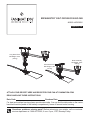 1
1
-
 2
2
-
 3
3
-
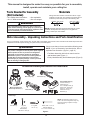 4
4
-
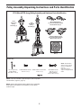 5
5
-
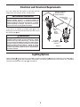 6
6
-
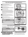 7
7
-
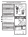 8
8
-
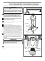 9
9
-
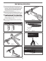 10
10
-
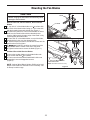 11
11
-
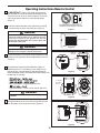 12
12
-
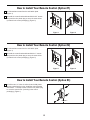 13
13
-
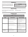 14
14
-
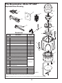 15
15
-
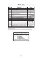 16
16
-
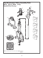 17
17
-
 18
18
-
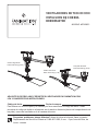 19
19
-
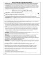 20
20
-
 21
21
-
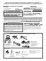 22
22
-
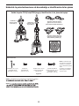 23
23
-
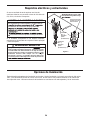 24
24
-
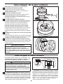 25
25
-
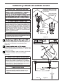 26
26
-
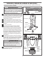 27
27
-
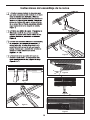 28
28
-
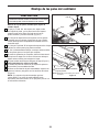 29
29
-
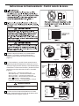 30
30
-
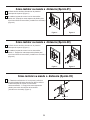 31
31
-
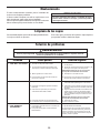 32
32
-
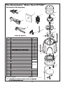 33
33
-
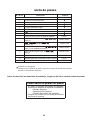 34
34
-
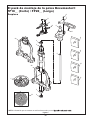 35
35
-
 36
36


Fanimation Brewmaster FP1280 El manual del propietario
- Categoría
- Ventiladores domésticos
- Tipo
- El manual del propietario
en otros idiomas
Artículos relacionados
-
Fanimation BrewMaster El manual del propietario
-
-
-
-
-
-
-
-
-