Fanimation BrewMaster El manual del propietario
- Tipo
- El manual del propietario

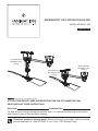
Support Directly From Building Structure
Short Neck FP10
Net Weight 11 lbs
(5.0 kg)
Motor Assembly
Net Weight 15 lbs
(6.8 kg)
Questions, problems, missing parts? Before returning to your retailer, call our customer
service department at 1-888-567-2055, 8 a.m.-5 p.m., EST, Monday-Friday.
Date Code
Purchase Date
ATTACH YOUR RECEIPT HERE AND REGISTER YOUR FAN AT FANIMATION.COM
READ AND SAVE THESE INSTRUCTIONS
For best and quick service please provide date code. You can find the date code on the Carton,
Wall Control, Frame of Fan and Motor Housing.
Long Neck FP20
Net Weight 15 lbs
(6.8 kg)
Español p. 18
BREWMASTER
®
BELT-DRIVEN CEILING FAN
MODEL #FP1280**-220

Additional Safety Instructions
Important Safety Instructions
WARNING: To avoid fire, shock and serious personal injury, follow these instructions.
1. Read your owner’s manual and safety information before installing your new fan. Review
the accompanying assembly diagrams.
2. Before servicing or cleaning unit, switch power off at service panel and lock service panel
disconnecting means to prevent power from being switched on accidentally. When the
service disconnecting means cannot be locked, securely fasten a warning device, such as a
tag, to the service panel.
3. Be careful of the fan and blades when cleaning, painting, or working near the fan. Always
turn off the power to the ceiling fan before servicing.
4. Do not insert anything into the fan blades while the fan is operating.
5. Do not operate reversing switch until fan blades have come to a complete stop.
6. Do not dispose of electrical appliances as unsorted municipal waste, use separate collec-
tion facilities.
7. Contact your local government for information regarding the collection systems available.
8. If electrical appliances are disposed of in landfills or dumps, hazardous substances can
leak into the groundwater and get into the food chain, damaging your health and well-being.
9. When replacing old appliances with new once, the retailer is legally obligated to take back
your old appliance for disposal at least for free of charge.
10. This appliance is not intended for use by persons (including children) with reduced
physical, sensory or mental capabilities, or lack of experience and knowledge, unless they
have been given supervision or instruction concerning use of the appliance by a person
responsible for their safety. Children should be supervised to ensure that they do not play
with the appliance.
1. To avoid possible shock, be sure electricity is turned off at the fuse box before wiring, and
do not operate fan without blades.
3. The fan base must be securely mounted and capable of reliably supporting at least 15.9kg
(35 lbs). See page 6 of owner’s manual for support requirements.
4. CAUTION: To reduce the risk of personal injury, mount the fan base to a ceiling joist or
structural member using the hardware provided with your fan.
WARNING:
WARNING: The fan cannot be installed on a sloped ceiling.
Support Directly from Building Structure.
5. The fan must be mounted at least 2.3 m from the floor to prevent accidental contact with
the fan blades.
6. Follow the recommended instructions for the proper method of wiring your ceiling fan.
7. Do not use the Solid-State speed control.
2. All wiring and installation procedures must satisfy National Electrical Codes and Local
Codes. The ceiling fan must be grounded as a precaution against possible electrical shock.
Assembled and installed installation shall be made or approved by licensed electrician.
WARNING: To reduce the risk of fire or electric shock, this fan should only be used with Fan
Speed Control Part No. C3-220, manufactured by Rhine Electronic Co., Ltd.
WARNING: TO REDUCE THE RISK OF SHOCK, THIS FAN MUST BE INSTALLED WITH
AN ISOLATING WALL CONTROL/SWITCH.
WARNING: This product is designed to use only those parts supplied with this product and/or
accessories designated specifically for use with this product. Using parts and/or accessories
not designated for use with this product could result in personal injury or property damage.
WARNING: To reduce the risk of personal injury, do not bend the blade bracket (flange or
blade holder) when installing the brackets, balancing the blades, or cleaning the fan. Do not
insert foreign objects in between swing fan blades

LIMITED LIFETIME WARRANTY
1. LIMITED LIFETIME MOTOR WARRANTY - If any part of your fan motor fails, due to a
defect in materials or workmanship during the lifetime of the original purchaser, Fanimation
will provide the replacement part free of charge, when the defective fan is returned to our
national service center. Proof of purchase is required. Customer shall be responsible for all
costs incurred in the removal or reinstallation and shipping of the product for repairs or
replacement.
2. ONE YEAR MOTOR LABOR WARRANTY - If your fan motor fails at any time within one
year from the original purchase, due to defects in materials or workmanship, labor to repair
the motor will be provided free of charge at our national service center. Purchaser will be
responsible for labor charges after this one-year period. Customer shall be responsible for
all costs incurred in the removal or reinstallation and shipping of the product for repairs or
replacement.
3. If any other part of your fan fails at any time within one year after original purchase, due to
a defect in materials or workmanship, we will repair, or replace, at our option, the defective
part free of charge for parts and labor performed at our national service center.
4. Because of varying climate conditions, this warranty does not cover changes in the finish,
including rusting, pitting, corroding, tarnishing, or peeling.
5. This warranty is void and does not apply to damage from improper installation, neglect,
accident, misuse, exposure to extremes of heat or humidity, or as a result of any modifica-
tion to the original product.
6. All costs of removal and reinstallation of the fan are the sole responsibility of the owner of
the fan and not the store that sold the fan or Fanimation.
7. Fanimation reserves the right to modify or discontinue any product at any time and may
substitute any part under this warranty.
8. Under no circumstances may a fan be returned without prior authorization from Fanima-
tion. The receipt of purchase must accompany authorized returns and must be sent freight
prepaid to Fanimation. The fan to be returned must be properly packed to avoid damage in
transit; Fanimation will not be responsible for any damage resulting from improper packag-
ing.
9. It is understood that any repair or replacement is the exclusive remedy available from
Fanimation. There is no other expressed or implied warranty. Fanimation hereby disclaims
any and all implied warranties, including, but not limited to those of merchantability and
fitness for a particular purpose to the extent permitted by law. Some states do not allow
limitations on implied warranties. Fanimation will not be liable for incidental, consequential,
or special damages arising out of or in conjunction with product use or performance, except
as may otherwise be accorded by law. This warranty gives you special legal rights and you
may also have other rights that vary from state to state.
10. A certain amount of wobble is normal and should not be considered a problem or a
defect.
Table of Contents
(Motor Assembly) Unpacking Instructions and Parts
Identification . . . . . . . . . . . . . . . . . . . . . . . . . . . . . . . . . . .4
(Pulley Assembly) Unpacking Instructions and Parts
Identification . . . . . . . . . . . . . . . . . . . . . . . . . . . . . . . . . .5
Electrical and Structural Requirements . . . . . . . . . . . . . 6
How to Hang and Wire Your Ceiling Fan. . . . . . . . . . . . . 7
Belt Splicing Instructions. . . . . . . . . . . . . . . . . . . . . . . . 10
Mounting the Fan Blades . . . . . . . . . . . . . . . . . . . . . . . . 11
Operating Your C3-220 Wall Control . . . . . . . . . . . . . . . 12
Maintenance . . . . . . . . . . . . . . . . . . . . . . . . . . . . . . . . . . 12
Blade Cleaning . . . . . . . . . . . . . . . . . . . . . . . . . . . . . . . . 12
Trouble Shooting . . . . . . . . . . . . . . . . . . . . . . . . . . . . . . 13
Exploded-View Illustration & Parts List, Motor Assembly
. . . . . . . . . . . . . . . . . . . . . . . . . . . . . . . . . . . . . . . . . . . . . .14
Parts List, Pulley Assembly . . . . . . . . . . . . . . . . . . . . . . 15
Exploded-View Illustration, Pulley Assembly. . . . . . . . 16
Extends to the original purchaser of a Fanimation fan from an authorized Fanimation dealer/retailer only

WARNING
Installed Wire Length Wire Size A.W.G.
1 ( mm
2
)
( mm
2
)
Up to 15.24 m (50 ft.)
15.24–30.48 m (50 –100 ft.)
Unpacking Instructions and Parts Identification
For your convenience, check-off each step. As each step is completed, place a check mark. This will ensure that all
steps have been completed and will be helpful in finding your place should you be interrupted.
Wiring outlet box and box connectors must be of type re-
quired by local code. The minimum wire would be a 3-con-
ductor (2-wire with ground) of the following size:
Place the parts from the loose parts bags in a
small container to keep them from being lost. If any parts
are missing, contact your local retailer.
Materials
Check to see that you have received the following parts:
If you are uncertain of part description, refer to
exploded view illustration.
Assembly with hardware parts (Figure 1)
Assembly and hardware parts (Figure 2)
WARNING
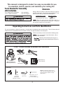
This manual is designed to make it as easy as possible for you
naf gniliec ruoy niatniam dna ,etarepo ,llatsni ,elbmessa ot
Tools Needed for Assembly
(Not Included)
• One Phillips head screwdriver
• One ¼˝ blade screwdriver
• One stepladder
• One wire stripper
Belt Clamps (2)
Rivet Tool (1)
Punch Tool (1)
Wall Control (1)
#6-32 screws (2)
“J” Lag Bolt,
1/4” x 2” (1)
Rivets, 3/32” x 7/32” (8)
& Rivet Washers,
0.1 x 0.23 x 0.35 mm (8)
FP1280
Motor Assembly with
Switch Cap Receiver (1)
NOTE: The illustration shown is not to
scale or its actual configuration may vary.
Parts and packings subject to change
without notice.
Wire Nuts (3) Lag Bolt,
1/4” x 2” (4)
Flat Washers,
Ø5 x Ø14 x 1mm (4)
Hardware Bags
FP1280**-220 Motor Assembly and Hardware Parts Identification

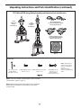
Unpacking Instructions and Parts Identification (continued)
Wood Blade Screws,
3/16”-24 x 1/2” (7)
& Fiber Washers,
Ø12.5 x Ø5 x 1mm (7)
Blade Holder to Hub Screws,
10-32 x 1/2” (5)
1/4” x 2 Lag Bolts (4),
& Flat Washers,
Ø5 x Ø14 x 1mm (4)
Traditional Blade Screws,
3/16”-24 x 3/8” (5)
Hardware Bags
FP10 (Short)/FP20 (Long) Pulley Assembly and Hardware Parts Identification
NOTE: If you are uncertain of part description, refer to exploded
view illustration. (Figure 2, page 17)
NOTE: Optional Wood Blade Holders (BH20 series) and B4000
wood blades are available for this assembly. Not for Damp
Location usage.
Wood Blade Holders
(for use with FP1022, FP1026,
FP1030 blade sets) (2)
Traditional Blade Holders
(for use with Palm, Bamboo,
Wicker blade sets) (2)
FP20
Short Neck
Pulley
Assembly (1)
Belt (1)
NOTE: The illustration
shown is not to scale or
its actual configuration
may vary.
Parts and packings
subject to change without
notice.
FP10
Short Neck
Pulley
Assembly (1)

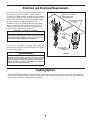
Lighting Options
Optional lighting fi tters and light kits are available, including a single bowl fi xture with a maximum of 180 watts and a
variety of four light fi xtures with a maximum of 240 watts. Can be only mounted on the motor switch cup. Installation
instructions provided with each light fi tter and light kit.
Electrical and Structural Requirements
Figure 3
5 cm Lag Bolt
& Flat Washer
(4 places)
5 cm
Lag Bolt
& Flat
Washer
(4 places)
Outlet Box Flush
to Finished
Ceiling
Plywood (2 cm thick min.)
Backing Secured to
Structural Member
If your fan is to replace an existing light fixture, turn
electricity off at the main fuse box at this time and remove
the existing light fixture.
WARNING
Turning off wall switch is not sufficent. To avoid
possible electrical shock, be sure electricity is turned
off at the main fuse box before wiring. All wiring must
be in accordance with National and Local codes and the
ceiling fan must be properly grounded as a precaution
against possible electrical shock.
Your new fan will require a grounded electrical supply line
of 220-240 volts AC, 50 Hz circuit. The fan shall be
mounted on a reliable surface, building structure, capable
of supporting a load of at least 15.9 kg. If an outlet box is
used, it must be suitable for fan support, and be marked
as such. Otherwise it need to be replace by an
appropriate one. If you exchange the outlet box, make
such the electricity is switched off at the main fuse box.
Figure 3 depicts different structural configurations that
may be used for mounting the outlet box.
INSTALLATION NOTE
It is recommended that each fan and the motor have
0.02 m plywood backing secured to a structural member
for adequate support (Figure 3). The motor unit will not
operate more than 2 pulley/blade assemblies.

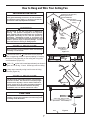
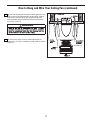
How to Hang and Wire Your Ceiling Fan
You will first drill 4.76 m pilot holes into the plywood
base or supporting member to prevent splitting or cracking.
Mount the Pulley Assembly on the ceiling with 4 lag bolts
and flat washers (Figure 1a).
Drill 4.76 m pilot hole located approximately as shown in
Figure 1a & 1b for lag “J” hook. Screw lag hook into ceiling.
Hang motor assembly on lag hook for ease of wiring
fan motor (Figure 1b).
Floor
Ceiling
No
less than
2.3 m
4.27 m max - motor to head
1.22 m min
(4.11 m max - head to head)
Figure 1a
Figure 2
5 cm Lag Bolt
& Flat Washer
(4 places)
5 cm Lag
Bolt
& Flat
Washer
(4 places)
Outlet Box Flush
to Finished
Ceiling
Plywood ( 2 cm thick min.)
Backing Secured to
Structural Member
Figure 1b
CAUTION
Do not connect fan blades until the fan is completely
installed. Hanging fan with blades connected may result
in damage to the fan blades.
INSTALLATION NOTE
WARNING
Do not install or use fan if any part is damaged or
missing. This product is designed to use only those
parts supplied with this product and/or any accessories
designated specifically for use with this product by
Fanimation. Substitution of parts or accessories not
designated for use with this product by Fanimation could
result in personal injury or property damage. Contact
your retail store for missing or damaged parts.
INSTALLATION NOTE
evah rotom eht dna naf hcae taht dednemmocer si tI
2 cm plywood backing secured to a structural member
for adequate support (Figure 1). The motor unit will not
operate more than 4 pulley/blade assemblies.
INSTALLATION NOTE
Motor assembly can be mounted at either end of Pulley
assembly or in the middle.
The fan must be hung with at least 2.3 m of clearance
from floor to blade. The maximum overall (belt) length
between motor & pulley is 4.27 m and the minimum is
1.22 m. (Figure 2) For two-pulley assembly installation:
The maximum overall distance between two pulley
assemblies is 4.11 m and the minimum is 1.52 m.

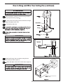
How to Hang and Wire Your Ceiling Fan (continued)
Mount retainer to junction box with screws (provided
with your junction box). (Figure )
Loosen strain relief and pull excess lead wires through
canopy. Re-tighten strain relief.
Cut and strip lead wires.
▲
WARNING
▲
WARNING
N L1 L
Terminal
Block
BRN
TO HOT
YEL/GRN from
220-240 VAC SUPPLY
(User Supplied)
ORG-TO LIGHT
BRN-TO MOTOR
BLUE-NEUTRAL
BRN
TO FAN
BLUE/BLK
(NEUTRAL)
RED/BRN
(HOT)
YEL/GRN
(EARTH)
Wall Control
(Rear View)
Attach wall control unit to outlet box using the two
6-32 screws provided. (Figure 5)
Attach wall plate to the switch control front. (Figure 5)
WARNING
Supply wires and fan wires
omitted for clarity.

How to Hang and Wire Your Ceiling Fan (continued)
After the connections have been made, tighten the lag
bolts to secure fan base assembly to the ceiling, making
sure that the electrical wires are completely inside the
base assembly and not pinched between the base and
the ceiling. (Figure 6)
WARNING
Set Screws (2)
12. If the motor pulley is loose, please tighten the set
screws only. Do not try to adjust the motor pulley’s location.
(Figure 6)

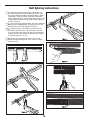
Belt Splicing Instructions
Wrap the belting around the two pulleys that will
be connected and overlap the belting as shown. Use
the spring clamps provided to hold the belting in place
temporarily. With the clamps remaining in the same
place, grasp both ends of the belting and pull tight. The
clamps should hold the belting together after releasing
the belt. (Figure 1)
Punch two holes (approximately 1/8 inch in diameter)
through the overlapping belts, spacing them one inch
apart with the punch tool supplied. (Figure 2)
Using the rivets, rivet washers, and the rivet tool
provided, install two rivets. The fl at head of the rivet
must be on the inside of the belt (the side touching the
pulley), while the rivet washer is placed on the outside
of the belt. (Figures 3, 4, & 5)
Trim the excess belting as shown. The overlap
should be approximately one to two inches in length.
(Figures 6 & 7)

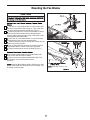
Mounting the Fan Blades
Lay side “A” of the blade holder on a fl at surface with
the inside of the blade holder facing up. This is the side
with the threaded posts and pitched foot (Figure 1).
Position the palm leaf, or the woven bamboo or wicker
blade over the blade holder with the threaded posts
showing. Make sure the bottom edge of the blade is fully
seated against the blade holder.
Place side “B” of the blade holder on top of the blade,
positioning the holes over the threaded posts.
With a Phillips screwdriver, thread both screws into the
posts but do not fully tighten.
Prior to fi nal tightening, position the center line of the
blade holder with the center of the end of the blade.
Tighten both screws to secure the blade (Figure 1).
Mount the wooden blades on the blade holder with
three screws and three fi ber washers .
Then mount the assembled blade/blade holder onto
the fl ywheel, secure with fl ywheel screws.
(Figure 2)
Optional Wood Blade Holders (BH20 series) and
B4000 wood blades are available for this assembly. Not
for Damp Location usage.
Blade detail omitted for clarity.
CAUTION

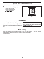
Maintenance
Periodic cleaning of your new ceiling fan is the only
maintenance that is needed. When cleaning, use only a
soft brush or lint free cloth to avoid scratching the finish.
Abrasive and/or non-abrasive cleaning agents are not
required and should be avoided to prevent damage to
finish.
Blade Cleaning
Periodic light dusting of the Palm Leaf, Woven Bamboo,
Wooden, or Wicker blades is recommended. A feather
duster will work best.
Avoid using water, cleansers, or harsh rags, which can
warp and ruin the blades.
CAUTION
Operate Your C3-220 Wall Control
Restore electrical power and operate your fan by rotating
the control knob to desired setting (Figure 1):
st
Position – low fan speed
nd
Position – medium fan speed
rd
Position – high fan speed
ff

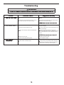
Troubleshooting
WARNING
Trouble Probable Cause Suggested Remedy
Fuse or circuit breaker blown.
Loose power line connections to the fan, or loose
switch wire connections in the switch housing.
Check main and branch circuit fuses or circuit
breakers.
Check line wire connections to fan and switch wire
connections in the switch housings.
Loose screws in motor housing.
Screws securing fan blade are loose.
Motor noise caused by solid state variable speed
control.
Pulley set screw loose.
Rivets (on belt) make clicking sound.
Check to make sure all screws in motor housing are
snug (not over-tight).
Check to make sure the screws which attach the fan
blade to the are tight.
Some fan motors are sensitive to signals from
solid-state variable speed controls. Solid-state controls
are not recommended, choose an alternative control
method.
Tighten set screw securely.
Not considered a defect.
Fan / Motor base lag bolts on the ceiling is loose.
Blade holders not seated properly.
Tighten lag bolts securely.
Check to be sure the fan blade holders seat firmly
and uniformly to the surface of the hub. If holders are
seated incorrectly, loosen the screws retighten.

17
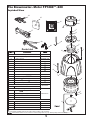
The Brewmaster
®
Motor FP1280**-220
Exploded-View
The illustration shown is not to scale or its actual configuration may vary. Wires partially removed for clarity.
18
14
19
1
2
3
6
4
9
8
10
12
13
11
Brewmaster Motor Assembly
FMA1280**-220
1 Switch Cap Assembly
1a Wiring Harness
AP3247**
AP128099**-220
P106**
2 Nut
3 Flat Washer
4 Switch Cap Base
5 Motor Pulley
6 Motor Housing
7 M/S, Washer Hd,
, Black
8 Motor Assembly
9 Hex Nut,
-24 x 4mm (4)
10 Lock Nut, Nylon Insert, -24 x 5mm (4)
11 Canopy Assembly
SPCA1280-220
Belt Rivet Parts Bag Containing:
HDW1280RV
15 Rivets with Rivet Washers
Loose Assembly Parts Bag Containing:
HDW1280LP**
12 Lag Bolt, , Black (4)
13 Flat Washer,
, Black (4)
19 “J” Hook
20 Wire Connectors (3)
Miscellaneous Tools & Control
14 Rotary Wall Control
C3-1280-220
16 Clamps (2)
P128015
17 Rivet Tool
P128005
18 Punch Tool
P128010
Non-Sevicable Items
Parts List
7
20
15
16
Insert FINISH CODES (Refer to fan model number located on fan assembly)
21
21
5
21 Set Screw 5/16-18 x 3/8 W/Locktite
*
1a

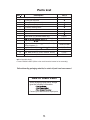
Pulley Assembly
FP10**/FP20**
1 Pulley with set screw
2a Short Frame (Short model)
2b Long Frame (Long model)
3 Cushion, Bearing, Black
4 Bearing
5 Shaft
6 Hub
7 Blade Holder (2) (Wooden Blades only)
P1212**
8 ,Black (5) HDWFP10HB**
9 Bag, Lag Bolt,
, Black, w/washers (4) HDWFP10LG
10 Bag, Wood Blade Screw,
-24 x ½ ,Black (7),
w/Fiber Washers (7)
HDWFP10WB**
11 Bag, Trad. Blade Screw,
-24 x ,Black (5) HDWFP10TB**
12 Blade Arm Cover (2)
P3220**
13 Trad. Blade Holder (2) (Palm, Bamboo, Wicker)
14 Belt (one 9.14 m roll)
P3210**
BM30
Before discarding packaging materials, be certain all parts have been removed
How to Order Parts
When ordering repair parts, always
give the following information:
Contact your retail store for repair parts.
Parts List
Insert FINISH CODES (Refer to fan model number located on fan assembly)
Non-Sevicable Items
Ref # Description Part #
*

The illustration shown is not to scale or its actual configuration may vary.
Exploded-View
8
The Brewmaster
®
Pulley Assembly Pack
FP10__ (Short) / FP20__ (Long)
7
11
6
5
3
4
2a
2b
1
3
4
14
9
8
9
10
11
12
13
10

2020/10 V.01
Copyright 2020 Fanimation
10983 Bennett Parkway
Zionsville, IN 46077
Phone: 888-567-2055
Outside U.S.: 317-733-4113
FAX: 866-482-5215
FANIMATION.COM

6
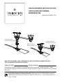
VENTILADORES DE TECHO CON
IMPULSION DE CORREA
BREWMASTER
®
MODELO #FP1280**-220
Preguntas, problemas, piezas faltantes? Antes de volver a la tienda, llame a nuestro
Departamento de Servicio al Cliente al 1-888-567-2055, 8 a.m. - 5 pm, hora del Este, de
lunes - viernes.
Fecha de compra
ADJUNTE SU RECIBO AQUÍ Y REGISTRE SU VENTILADOR EN FANIMATION.COM
LEA Y GUARDE ESTAS INSTRUCCIONES
Para ofrecer un servicio rápido y de calidad, por favor suministre el código de fecha. Puede
encontrar el código de fecha en el paquete, Control de pared, marco del ventilador o en la carcasa
del motor.
Cuello corto FP10
Peso neto 5.0 kg (11 lb)
Conjunto del motor
Peso neto 6.8 kg (15 lb)
Cuello Largo FP20
Peso neto 6.8 kg (15 lb)
Código de fecha

GARANTÍA LIMITADA DE POR VIDA DEL MOTOR - Si se produjera una falla en alguna de las partes del motor de su ventilador debido 1.
a un defecto en los materiales o en la fabricación durante el tiempo de vida del comprador original, Fanimation proporcionará la pieza de
repuesto sin cargo una vez que el ventilador defectuoso sea devuelto a nuestro centro de servicios nacional. Se requiere comprobante de
venta. El cliente se hará responsable de todos los gastos de remoción o reinstalación y envío del producto para reparaciones o sustitución.
GARANTÍA DE MANO DE OBRA DEL MOTOR POR UN AÑO - Si el motor de su ventilador fallara antes de cumplirse un año a partir del2.
momento de su compra original debido a defectos en los materiales o en la fabricación, se le efectuará la reparación del mismo sin cargo
en nuestro centro de servicios nacional. El comprador se hará responsable de los gastos de mano de obra luego del período de un año.
El cliente se hará responsable de todos los gastos de remoción o reinstalación y envío del producto para reparaciones o sustitución.
Si otra pieza del ventilador fallara dentro del período de un año a partir de la fecha de compra original debido a un defecto en los3.
materiales o en la fabricación, repararemos o sustituiremos, según creamos conveniente, la pieza defectuosa sin cargo alguno en
nuestro centro de servicios nacional.
Debido a las diversas condiciones climáticas, esta garantía no cubre cambios en la terminación, incluidos oxidación, corrosión,4.
falta de brillo o peladuras.
Esta garantía es nula y no se aplica a daños por instalación incorrecta, negligencia, accidentes, uso indebido, exposición al calor o5.
a la humedad en exceso, o como resultado de cualquier modificación realizada al producto original.
Todos los gastos de remoción y reinstalación del ventilador son responsabilidad exclusiva del propietario, y no de la tienda que6.
vendió el ventilador ni de Fanimation.
Fanimation se reserva el derecho de modificar o discontinuar un producto en cualquier momento, o sustituir cualquier pieza según7.
lo establecido por esta garantía.
En ningún caso se podrá devolver un ventilador sin previa autorización por parte de Fanimation. Las devoluciones autorizadas8.
deberán ir acompañadas del recibo de venta y deberán enviarse a Fanimation, previo pago del flete. El ventilador que se devuelva
deberá estar embalado en forma adecuada a fin de evitar daños durante el transporte. Fanimation no se hará responsable de los
daños que resulten del embalaje incorrecto del producto.
Se entiende que las reparaciones y las sustituciones son el único recurso disponible de Fanimation. No existe ninguna otra9.
garantía expresa o implícita. Por la presente, Fanimation niega todas las garantías implícitas, que incluyen, entre otras, la
comerciabilidad y la aptitud para determinado fin hasta donde la ley lo permita. Algunos estados no permiten limitaciones sobre las
garantías implícitas. Fanimation no se hará responsable por daños accidentales, resultantes o especiales derivados del uso o el
rendimiento del producto o en conjunción con éste, excepto en los casos en los que la ley así lo disponga. Esta garantía le otorga
derechos legales especiales y es posible que también goce de otros derechos que pueden variar según el estado.
Es normal que se produzca un cierto movimiento oscilante y esto no debe considerarse un problema o defecto.10.
GARANTÍA LIMITADA DE POR VIDA
Instrucciones de seguridad importantes
ADVERTENCIA: Siga estas instrucciones para prevenir incendios, descargas eléctricas y lesiones personales graves.
Lea el manual del propietario y la información de seguridad antes de instalar su nuevo ventilador. Observe los diagramas de1.
ensamblaje adjuntos.
Antes de llevar a cabo el mantenimiento o la limpieza de la unidad, desconecte la electricidad en el panel de servicio y bloquee los2.
medios de desconexión del mismo para evitar que se active accidentalmente. Si no se pueden bloquear los medios de desconexión
del servicio, coloque un dispositivo de advertencia, como una etiqueta, en el panel de servicio.
Tenga cuidado con la estructura y las aspas del ventilador cuando limpie, pinte o trabaje cerca del mismo. Desconecte siempre la3.
electricidad del ventilador de techo antes de llevar a cabo el mantenimiento.
No coloque nada en las aspas del ventilador cuando éste se encuentra en funcionamiento.4.
No accione el conmutador inversor hasta que las aspas del ventilador se hayan detenido por completo.5.
Instrucciones de seguridad adicionales
Las aspas del ventilador deben instalarse por lo menos a 2 m (7 pies) del suelo, a fin de evitar un contacto accidental con las mismas.5.
Para evitar posibles descargas eléctricas, asegúrese de que la electricidad esté desconectada en la caja de fusibles antes de realizar la
instalación eléctrica, y no haga funcionar el ventilador sin las aspas.
Todos los procedimientos de conexión eléctrica e instalación deben cumplir con los Códigos eléctricos nacionales (ANSI/NFPA ) y
Códigos locales. El ventilador de techo debe estar conectado a tierra a fin de prevenir posibles descargas eléctricas. La instalación
eléctrica debe ser llevada a cabo o aprobada por un electricista autorizado.
La base del ventilador debe estar adecuadamente instalada y sea capaz de soportar de forma fiable al menos 100 libras (el ventilador y
los accesorios no exceden las 35 libras). Las cajas de electricidad no son adecuadas para el soporte del ventilador. Consulte la página
21 del manual del propietario para ver los requisitos de soporte. Consulte un electricista cualificado si tuviera alguna duda.
Para reducir el riesgo de daños personales, instale la base del ventilador en una viga o parte de la estructura utilizando
el equipo suministrado con su ventilador.
Siga las recomendaciones sobre el método correcto de instalación eléctrica de su ventilador de techo. Si no posee la experiencia o6.
los conocimientos eléctricos adecuados, contrate a un electricista autorizado para instalar el ventilador.
Apto para usar con controles de velocidad de estado sólido.7.
Este producto está diseñado para ser usado sólo con las piezas suministradas o los accesorios indicados
específicamente para el mismo. Si utiliza piezas o accesorios que no están indicados para su uso con este producto, podría
sufrir lesiones personales o dañar el ventilador. ADVERTENCIA: Este producto está diseñado para ser usado sólo con las piezas
suministradas o los accesorios indicados específicamente para el mismo. Si utiliza piezas o accesorios que no están indicados para su
uso con este producto, podría sufrir lesiones personales o dañar el ventilador.
Para reducir el riesgo de lesiones personales, no doble los soportes de las aspas (borde o soporte de aspas) al instalar
los soportes, balancear las aspas o limpiar el ventilador. No coloque objetos extraños entre las aspas del ventilador en funcionamiento.
Para reducir el riesgo de descargas eléctricas, este ventilador se debe instalar con un control/interruptor de pared aislado.
Soporte directo desde la estructura del edificio.
Para reducir el riesgo de incendios o descargas eléctricas, este ventilador solo debería ser utilizado con la pieza de
control de velocidad del ventilador Nº UC7067RY fabricada por Rhine Electronic Co., Ltd.
Tabla de contenidos
(Unidad del motor) Instrucciones de desembalaje e Montaje de las palas del ventilador. . . . . . . . . . . . . . . . . . 27
identificación de las piezas . . . . . . . . . . . . . . . . . . . . . . .20
. . . . 28
(Unidad de la polea) Instrucciones de desembalaje e
Mantenimiento . . . . . . . . . . . . . . . . . . . . . . . . . . . . . . . . . .28
identificación de las piezas . . . . . . . . . . . . . . . . . . . . . . 21
Limpieza de las aspas . . . . . . . . . . . . . . . . . . . . . . . . . . . .
28
Requisitos eléctricos y estructurales . . . . . . . . . . . . . . . 22
Solución de problemas . . . . . . . . . . . . . . . . . . . . . . . . . . . .29
Opciones de iluminación. . . . . . . . . . . . . . . . . . . . . . . . . .22
Ilustración del despiece . . . . . . . . . . . . . . . . . . . . . . . . . . . 30
Instalación y cableado del ventilador de techo . . . . . . . 23
Lista de piezas, unidad de la polea. . . . . . . . . . . . . . . . . . .31
Instrucciones del ensamblaje de la correa. . . . . . . . . . . 6 2
Plano de despiece, unidad de la polea. . . . . . . . . . . . . . . .32
Se extiende al comprador original del ventilador Fanimation solo desde un distribuidor/minorista autorizado de Fanimation
ADVERTENCIA: El ventilador no se puede instalar en un techo inclinado.

• Unidad del motor del ventilador con las piezas del
equipo (Figura 1)
• Unidad del cabezal de la polea y piezas del equipo
(Figura 2)
Verifique que haya recibido las siguientes piezas:
Si no está la una
Instrucciones para el desempaque
Para su comodidad, marque cada uno de los pasos. A medida que completa cada paso, coloque una marca de verificación.
Con esto se asegurará de completar todos los pasos y podrá saber desde dónde retomar si fuera interrumpido.
ADVERTENCIA
La caja de distribución eléctrica y los conectores de la caja deben ser del tipo
requerido por el código local. El cable más pequeño debe ser un cable de tres
conductores (de dos conductores con conexión a tierra) del siguiente tamaño:
coloque las e las s s en un
que se Si faltan n-
Materiales
tamaño del cable según el A.W.G.
(Calibre de Alambre Estadounidense)
longitud del cable instalado
1
1
hasta 15,2 m (50 pies)
de 15,2 a 30,5 m (50 a 100 pies)
ADVERTENCIA
• Destornillador Phillips
• Escalera de tijera
• Pelacables
Herramientas necesarias para el ensamblaje
(No incluido)
Figura 1
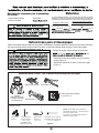
Remachadora (1)
Perforadora (1)
Tirafondo con
forma de “J”,
1/4” x 2” (1)
Remaches, 3/32” x 7/32” (8)
y arandelas de los remaches,
0.1 x 0.23 x 0.35 mm (8)
Tuercas de
cable (3)
Tirafondos de la
unidad del motor,
1/4” x 2” (4) y
arandelas planas,
Ø5 x Ø14 x 1mm (4)
Unidad del motor FP1280**-220 e identificación de las piezas del equipo
FP1280
Unidad del motor con
el receptor de la tapa
del interruptor (1)
Pinzas de la correa (2)
Bolsas de accesorios
NOTA: La ilustración que se muestra no
está hecha a escala y su c guración real y/o
terminación puede variar.
Las piezas y el embalaje están sujetos a
cambios sin previo aviso.
Control de pared de C3-220 (1)
Tornillos #6-32 (2)

Instrucciones para el desempaque (cont.)
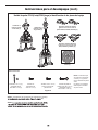
NOTA: La ilustración que
se muestra no está hecha
a escala y su c guración
real y/o terminación puede
variar.
Las piezas y el embalaje
están sujetos a cambios
sin previo aviso.
Tornillos de palas de
madera 3/16”-24 x 1/2” (7)
y Arandelas de fibra,
Ø12.5 x Ø5 x 1 mm (7)
Tornillos 10-32 x 1/2” (5)
para los soportes de
pala al centro
Tirafondos, 1/4 x 2” (4) y
Arandelas planas,
Ø5 x Ø14 x 1mm (4)
Tornillos de
pala tradicional,
3/16”-24 x 3/8” (5)
Soportes de pala de madera
(para su uso con los sets de
palas FP1022, FP1026, FP1030) (2)
Soportes de pala tradicional
(para uso en los sets de pala
Palm, Bamboo y Wicker) (2)
Unidad de la
polea de cuello
largo FP20 (1)
Correa (1)
Unidad de la
polea de cuello
corto FP10 (1)
Bolsas de accesorios
Figura 2
NOTA: la ilustración que se muestra no está hecha a escala y
35)
NOTA:
Unidad de polea FP10 (Corta)/FP20 (Larga) e identificación de las piezas del equipo

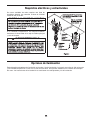
Requisitos eléctricos y estructurales
Si el ventilador reemplazará a una lámpara existente,
desconecte la electricidad de la caja de fusibles principal
y retire la lámpara.
ADVERTENCIA
Opciones de iluminación
Están disponible ajustadores de iluminación opcionales y kits de iluminación, incluyendo una tulipa de 180 vatios máx.
y una variedad de piezas de 4 luces con un máx. de 240 vatios. Solo pueden instalarse en la cubierta del interruptor
del motor. Las instrucciones de la instalación se suministran con cada ajustador y kit de iluminación.
NOTA LA INSTALACIÓN
Su nuevo ventilador de techo requiere una línea de
suministro eléctrico con conexión a tierra de 220-240
voltios de CA, de 50 Hz.

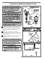
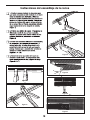
Instalación y cableado del ventilador de techo
1. En primer lugar, taladre los orificios guías de 3/16˝ en
la base de contrachapado o viga de sujeción para evitar
que se raje o rompa. Instale la unidad de la polea en el
techo con los 4 tirafondos y las arandelas planas.
(Figura 1a)
2. Taladre los orificios guías de 3/16˝ ubicados
aproximadamente como se muestra en la ilustración 1a y 1
b para el gancho tirafondo con forma de “J”. Atornille dicho
gancho en el techo.
3. Cuelgue la unidad del motor en el gancho del tirafondo
para facilitar el cableado del motor del ventilador.
(Figura 1b)
NOTA LA INSTALACIÓN
ADVERTENCIA
NOTA LA INSTALACIÓN
NOTA LA INSTALACIÓN
PRECAUCIÓN

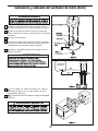
Monte la retención para la caja de empalme con los
tornillos (suministrados con la caja de empalme). (Figura 3)
Afloje el relevador de tensión y tire de los cables que
sobren a través de la cubierta. Vuelva a apretar el relevador
de tensión.
Corte y pele los cables.
▲
ADVERTENCIA
Instalación y cableado del ventilador de techo (Cont.)
▲ADVERTENCIA
N L1 L
Bloque
Terminal
BRN
AMA/VER desde la
220-240V CA SUMINISTRO
(No se incluyen)
Naranja a la iluminación
MAR – A motor
BRN
AZUL / NEGRO
AZUL / Neutro
(Neutro)
ROJO / NEGRO
(calor)
AMA/VER
(TIERRA)
Control de Pared
(vista posterior)
ADVERTENCIA
Fije la unidad de control de pared a la caja de
distribución eléctrica con los dos tornillos de 6-32
suministrados. (Figura 5)
Fije la placa de pared al frente del control de interruptor.
(Figura 5)
Conecte el cable de tierra amarillo / verde del ventilador
motor para el conductor de alimentación (esto puede ser un
aislamiento de color amarillo / verde). (Figura 4)
Realizar el cableado al bloque de terminales como se
muestra. (Figura 4)
ventilador
al ventilador
al calor
al calor

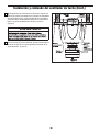
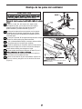
Instalación y cableado del ventilador de techo (Cont.)
Después de las conexiones se han hecho, apriete los
pernos de fijación para asegurar el conjunto de seguidores
de base hasta el techo, asegurándose de que los cables
eléctricos estén completamente dentro de la unidad de la
base y no quede atrapada entre la base y el techo.
(Figura 6)
▲
ADVERTENCIA
Tornillo de
fijación (2)
12. Si la polea del motor está floja, apriete únicamente los
tornillos de fijación. No intente ajustar la ubicación de la
polea del motor. (Figura 6)

Figura 1
Figura 7
Figura 6
Figura 5
Figura 4
Instrucciones del ensamblaje de la correa
Figura 2
Figura 3

Montaje de las palas del ventilador
Con un destornillador Phillips, enrosque ambos tornillos
en los pilotes pero no los ajuste por completo.
Ajuste ambos tornillos para asegurar el aspa (Figura 1).
Instale las palas de madera en el soporte de pala con
tres tornillos y tres arandelas de fibra.
Monte a continuación la pala ensamblada / soporte con
pala en el volante y asegúrelo con los tornillos del mismo
(Figura 2)
Detalle de la pala omitido para mejorar
la claridad.
PRECAUCIÓN
cubierta “B”Coloque la del soporte de aspas sobre el aspa,
y alinee los orificios sobre los pilotes roscados.
Antes de ajustarlos por completo, alinee la línea central
del soporte de aspas con el centro del extremo del aspa.
Ajuste ambos tornillos para asegurar el aspa.
Apoye el lado liso del soporte de aspas sobre
una superficie plana, con la parte interior del soporte
mirando hacia arriba. Este es el lado que tiene los
pilotes roscados y la base inclinada. (Figura 1).
Coloque las aspas sobre sus soportes con los postes
roscados que se muestran. Asegúrese de que el borde
inferior del aspa esté completamente asentado sobre el
brazo del aspa.

Se recomienda limpiar el polvo de las aspas periódicamente.
Lo mejor es utilizar un plumero.
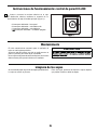
Mantenimiento
El único mantenimiento necesario para el ventilador de
techo es una limpieza periódica.
Al llevar a cabo la limpieza, use sólo un cepillo suave o un
paño sin pelusas, para evitar rayar el acabado.
No se requieren agentes abrasivos de limpieza; los mismos
deben evitarse para prevenir daños en el acabado.
PRECAUCIÓN
Limpieza de las aspas
Evite usar agua, productos de limpieza o trapos ásperos,
que pueden combar o dañar las aspas.
Instrucciones de funcionamiento: control de pared C3-220
Vuelva a conectar la corriente eléctrica en la caja
de distribución eléctrica mediante la conexión de la
electricidad en la caja de fusibles principal (Figure 1):
• 3 Interruptor deslizable = low speed
• 2 Interruptor deslizable = velocidad media
• 1 Interruptor deslizable = velocidad alta
•
Interruptor deslizable = ventilador apagado

Los interruptores de frecuencia del receptor de
control no se configuran.
Asegúrese de que coincidan los interruptores de
frecuencia del mando a distancia y del receptor.
Los tornillos que aseguran la pala del ventilador
están flojos.
Los tornillos de presión de la polea están flojos.
Los remaches (en la correa) están haciendo ruido. No se considera un defecto.
Los tirafondos de la base del motor / ventilador del
techo están flojos.
Los soportes de las palas no están asentadas
adecuadamente.
Fije adecuadamente los tirafondos.
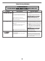
El fusible o el disyuntor están fundidos.
Las conexiones eléctricas del ventilador o del
interruptor en la caja del interruptor están flojas.
Batería agotada en el control remoto.
Revise los fusibles del circuito principal y derivado o
los disyuntores.
Revise las conexiones eléctricas del ventilador y del
interruptor en las cajas de los interruptores.
Reemplace con una batería nueva.
Hay tornillos flojos en la caja del motor.
Ruido del motor provocado por el control de
velocidad de estado sólido variable.
Asegúrese de que todos los tornillos de la caja del
motor estén bien ajustados (pero no en exceso).
Asegúrese de que los tornillos que fijan los soportes
de aspas al buje del motor del ventilador estén bien
ajustados.
Algunos motores de ventilador son sensibles a las
señales de los controles de velocidad de estado
sólido variables. Los controles de estado sólido no
son recomendables. Escoja un método de control
alternativo.
Ajuste bien los tornillos.
Asegúrese de que los soportes de las aspas del
ventilador estén colocados firmemente y de manera
uniforme en relación con la superficie de la caja del
motor. Si los soportes están mal colocados, afloje los
tornillos y vuelva a ajustarlos.
Solución de problemas
▲ADVERTENCIA
Problema Causa posible Solución sugerida

30
The Brewmaster
®
Motor Pack FP1280**-220
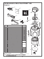
16 Pinzas de la correa (2)
P128015
17 Remachadora
P128005
18 Perforadora
P128010
Elementos no resistentes
Introduzcas los CÓDIGOS de acabo (Consulte el número de modelo del ventilador ubicado en la unidad del ventilador).
Figura 1
Despiece
NOTA:
17
18
14
19
2
3
6
4
9
8
10
11
7
20
15
16
21
21
5
Lista de piezas
N.º de ref. Descripción Pieza N.º
Unidad del motor Brewmaster
FMA1280**-220
1 Unidad de la carcasa del interruptor
AP3247**
1a Mazo de cables
AP128099**-220
2
Tuercas
3
Arandelas planas
12
4
Base de la carcasa del interruptor
5
Polea del motor
21
Tornillo de fijación de 5/16-18 x 3/8 con Loctite
13
6
Carcasa del motor
P106**
7
M/S, Arandela Hd, 3/16-24 x 3½”, Negro
8
Motor
9
Tuerca hexagonal 3/16-24 x 4mm (4)
10
Tuerca de bloqueo, inserción en nílon, 3/16-24 x 5mm (4)
11
Unidad de cubierta
SPCA1280-220
Bolsa de las piezas de los remaches de la correa que contiene:
HDW1280RV
15 Remaches y arandelas de los remaches (8)
Bolsa de las piezas sueltas que contiene:
12 Tirafondo, ¼ x 2”, Negro (4)
13 Arandela plana, ¼”, Negro (4)
HDW1280LP**
19 Gancho con forma “J”
20 Wire Connectors (3)
Control y Herramientas variadas
14 Mando a distancia
C3-1280-220
*
1
1a

1
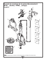
Unidad de la polea
FP10**/FP20**
1 Polea con tornillo de presión
2a Marco corto (modelo corto)
2b Marco largo (modelo largo)
3 Funda, rodamiento, negro
4 Rodamiento
5 Eje
6 Centro
7 Soporte de pala (2) (Solo de palas de madera)
P1212**
8 Bolsa, Tornillos de Soporte a Centro, 10-32 x ½˝,
Negro (5)
˝
HDWFP10HB**
9 Bolsa, Tirafondos, ¼˝ x 2˝, Negro, con
arandelas (4)
HDWFP10LG
10 Bolsa, Tornillos de pala de madera, 3/16˝-24 x ½˝,
Negro (7) con arandelas de fibra (7)
HDWFP10WB**
11 Bolsa, Tornillos de pala Trad.,3/16˝-24 x 3/8˝,
negro (5)
HDWFP10TB**
12 Cubierta del brazo de la pala (2)
P3220**
13 Soporte de pala Trad. (2) (Palmera, bambú o mimbre)
P3210**
14 Correa (un rollo de 30 pies) BM30
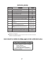
Lista de piezas
Introduzcas los CÓDIGOS de acabo (Consulte el número de modelo del ventilador
ubicado en la unidad del ventilador).
Elementos no resistentes
Cómo hacer un pedido de piezas
Al hacer un pedido de piezas de repuesto,
proporcione siempre la siguiente información:
• Número de pieza
• Descripción de la pieza
• Número de modelo del ventilador
Póngase en contacto con su tienda para obtener
las piezas de repuesto.
*

El pack de montaje de la polea Brewmaster®
FP10__ (Corto) / FP20__ (Largo)
7
11
6
5
3
4
2a
2b
1
3
4
9
8
12
13
10
la ilustración que se muestra no está hecha a escala y su configuración real puede variar.
Despiece
8
9
10
11
14

2020/10 V.01
Copyright 2020 Fanimation
Visite nuestro sitio Web en www.fanimation.com
10983 Bennett Parkway
Zionsville, IN 46077
Llame sin cargo al (888) 567-2055
FAX (866) 482-5215
Desde fuera de los EE.UU., llame al (317) 733-4113
-
 1
1
-
 2
2
-
 3
3
-
 4
4
-
 5
5
-
 6
6
-
 7
7
-
 8
8
-
 9
9
-
 10
10
-
 11
11
-
 12
12
-
 13
13
-
 14
14
-
 15
15
-
 16
16
-
 17
17
-
 18
18
-
 19
19
-
 20
20
-
 21
21
-
 22
22
-
 23
23
-
 24
24
-
 25
25
-
 26
26
-
 27
27
-
 28
28
-
 29
29
-
 30
30
-
 31
31
-
 32
32
-
 33
33


Fanimation BrewMaster El manual del propietario
- Tipo
- El manual del propietario
en otros idiomas
- English: Fanimation BrewMaster Owner's manual
Artículos relacionados
-
Fanimation Brewmaster FP1280 El manual del propietario
-
-
-
-
-
-
-
-
-