GE 20611 Instrucciones de operación
- Categoría
- Ventiladores domésticos
- Tipo
- Instrucciones de operación

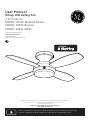
Note: Installation videos for GE Branded fans with SkyPlug technology
can be viewed and downloaded on www.gelightingandfans.com
120V 60Hz, MADE IN CHINA
Kinsey LED Ceiling Fan
1.12 m (44 in.)
MODEL: 20444 Brushed Nickel
MODEL: 20505 Bronze
MODEL: 20611 White
User Manual
Customer Assistance
1-866-885-4649
Contact a qualified electrician or call the Customer Care Service Team at 1-866-885-4649
Customer Service hours of operation are 9:00AM-5:00PM EST -Monday-Friday
Register your GE Branded fan for warranty coverage on
www.gelightingandfans.com
NV03-20180710

Safety Rules
1
READ AND SAVE THESE INSTRUCTIONS
1. To reduce the risk of electric shock, ensure electricity has
been turned off at the circuit breaker or fuse box before
beginning.
2. All electrical connections must be made in accordance
with local codes, ordinances and/or the National Electric
Code. Electrical installation should be performed by a
qualified licensed electrician.
3. WARNING: to reduce the risk of electrical shock or fire, do
not use this fan with any solid-state fan speed control device.
It will permanently damage the electronic circuitry.
4. CAUTION: To reduce the risk of personal injury, use only
the screws provided with the outlet box.
5. The weight of the fan is 7.66 kg (16.89 lb.). The outlet box
and support structure must be securely mounted and capable
of reliably supporting a minimum of 15.9 kg (35 lb.). Use only
UL Listed outlet boxes marked “FOR FAN SUPPORT.”
6. The fan must be mounted with a minimum of 2.1m (7 ft.)
clearance from the trailing edge of the blades to the floor.
7. Avoid placing objects in the path of the blades.
8. To avoid personal injury or damage to the fan and other
items, be cautious when working around or cleaning the fan.
9. Do not use water or detergents when cleaning the fan or
fan blades. A dry dust cloth or lightly damped cloth will be
suitable for cleaning.
10. After making electrical connections, spliced conductors
should be turned upward and pushed carefully up into
the outlet box. The wires should be spread apart with
the grounded conductor and the equipment-grounding
conductor on one side of the outlet box and ungrounded
conductor on the other side of the outlet box.
11. All screws must be checked and re-tightened where
necessary during installation.
12. This fan is suitable for room sizes up to 144 square feet
(13.38 square meters).
WARNING: To reduce the risk of
personal injury, do not bend the
blade arms (also referred to as
flanges), when installing the
brackets, balancing the blades
or cleaning the fan. Do not insert
foreign objects in-between
rotating fan blades.
WARNING: To reduce the risk of
fire, electric shock or personal
injury, mount to outlet box
marked “acceptable for fan
support of 15.9 kg (35 lb.) or less”
and use mounting screws
provided with the outlet box. Most
outlet boxes commonly used for
the support of light fixtures are
not acceptable for fan support
and may need to be replaced. Due
to the complexity of the
installation of this fan, a qualified
licensed electrician is strongly
recommended.
Min. 7ft/2.13m
Min. 30in/76cm
13. This fan is designed to be mounted on a flat ceiling only.
Do not mount fan on a sloped or vaulted ceiling.
NOTE: Fan must be installed at a
maximum distance of 6 m (20 ft.)
from the transmitting unit for
proper signal transmission
between the transmitting unit
and fan’s receiving unit.
CAUTION: Do not use wall switch
with dimmer function.

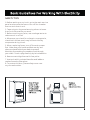
SAFETY TIPS
1. Before working on a circuit , go to the main service
panel and remove the fuse or turn off the breaker
that controls that circuit .
2
2. Tape a sign to the panel warning others to leave
the circuit alone while you work.
3. Before touching any wire, use a voltage tester to
make sure it’s not live.
4. Whenever you check for voltage in a receptacle,
check both outlets; each may be controlled by
a separate wiring circuit.
5. When replacing fuses, turn off the main power
first . Make sure your hands and feet are dry, and
place one hand behind your back to prevent
electricity from making a complete circuit through
your chest . Touch a plug fuse only by its insulated rim.
6. Remove cartridge fuses with fuse puller.
7. Use tools with insulated handles and ladders
made of wood or fiberglass.
8. To protect children, place safety cover over
any unused outlets.

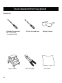
Tools Needed (Not Supplied)
3
Required
Philips Screwdriver
Safety Glasses
Step Ladder
Wire Stripper
Soft Cloth
Flathead Screwdriver
(#1 screwhead
recommended)

Carefully unpack and identify each part to make sure
you have everything ready for installation. Lay out
each part on a clean area such as a table or floor.
Check to make sure you have the following:
4
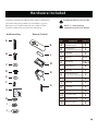
Hardware Included
A
A
2
C
C
2
G 1
E
E
12+1
12+1
I
L
2
M
O
2
B
B
2
D
D
H
K
1
L
N
1
F
F
4
J
M
1
N
Hardware Bag Remote Control
PART DESCRIPTION
Wood Screw (Long)
Fiber Washer
Transmitter
Receiver (Pre-installed
inside fan motor assembly)
Flat Washer
Plastic Wire Nut
AAA Battery
Wood Screw (Short)
Blade Screw
Balance Kit
Transmitter Holder
QUANTITY
+
-
O
Rubber Washer (7mm)
2
2
G
H
I
ATTENTION: Parts are not to scale.
NOTE: +1 = Extra quantity
supplied for future use if needed.
Rubber Washer (4mm)
(Pre-assembled to the SkyReceptacle)
J
1
K
Cover Plate
Mounting Screw
(Pre-assembled to the SkyReceptacle)
(Pre-assembled to the SkyReceptacle)
IM

5
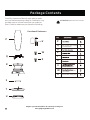
Carefully unpack and identify each part to make
sure you have everything ready for installation. Lay
out each part on a clean area such as a table or
floor. Check to make sure you have the following:
Package Contents
(Preassembled to canopy of
fan motor assembly)
(Pre-assembled to bottom of fan
motor assembly)
Light Kit Mounting Screw
(Pre-assembled to mounting plate)
ATTENTION: parts are not to scale.
Functional Fasteners
SkyReceptacle (Pre-assembled
with 4 mm rubber washer, mounting
screw and flat washer)
P
T
S
Q
U
V
W
R
X
P
T
S
Q
U
V
W
R
X
Register your GE Branded fan for warranty coverage on
www.gelightingandfans.com

6
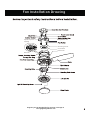
Fan Installation Drawing
Receptacle Slot
SkyReceptacle
Mounting Screw
Cover Plate
Push Lever
SkyPlug
Receiver
Register your GE Branded fan for warranty coverage on
www.gelightingandfans.com

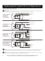
SkyReceptacle Typical Wire Configurations
7
TYPICAL WIRE CONFIGURATIONS:
Black (Live)
Black (Live 1)
Black
Black
Red (Live 2)
White
White
White
White
White
Black (Live)
Wire Nut
White
Green
Green
Green
Green
WIRING DIAGRAM #1:
Typical Wiring
Configuration
for 1 Wall Switch
WIRING DIAGRAM #2:
Typical Wiring
Configuration
for 2 Wall Switches
WIRING DIAGRAM #3:
Typical Wiring
Configuration
for 2 Wall Switches
WIRING DIAGRAM #4:
Wiring Configuration
with more than 1
of the same colored
wires in the outlet box
NOTE: If you do not have standard wiring configurations and have questions about the wiring in
your outlet box, please contact a qualified electrician, or call customer service 1-866-885-4649.
NOTE: If you have multiple wires connected together, add a jumper lead and insert jumper lead
into terminal. Only one single wire can be inserted into terminal.
View Installation Video@ www.gelightingandfans.com
IMPORTANT: For remote control fans, L1 is the only active live /hot terminal. The hot/live wire
from house supply must be inserted into L1 terminal for the fan to operate.

SkyReceptacle Installation
4mm rubber washer (pre-installed)
7mm rubber washer
4mm rubber washer
7mm rubber washer
7mm rubber washer
7mm rubber washer
4mm rubber washer
0-1.5mm
0-1.5mm Gap
1.5-3mm Gap
>3mm Gap
>3mm
1.5-3mm
Important: Always install SkyReceptacle with rubber washers to avoid a gap or uneven
surface, and to ensure proper placement of receptacle on the ceiling.
If your box is flush with the ceiling, or recessed less than 1.5mm, install with 4mm rubber washers.
If your box is recessed between 1.5mm and 3mm, use 7mm rubber washers.
If your box is recessed more than 3mm, use 7mm and 4mm rubber washers.
8
4mm rubber washer
4mm rubber washer

SkyReceptacle Installation
9
1/2"/12.7mm
Outlet Box
(not Supplied)
Sky
Receptacle
Terminal’s Bottom view
on Sky Receptacle
1
2
OK
Not
OK
Not
OK
Note : If you do not have standard
wiring configurations, please contact a
qualified electrician, or call customer
service 1-866-885-4649.
Insert wires into terminal, tighten
screw to secure wires.
Screw torque 6.3 lb-in.

SkyReceptacle Installation
10
Using the rubber washer when installing receptacle ensures proper placement of the
receptacle on the ceiling. We recommend using the rubber washers in all installations.
Rubber Washer
3
Install cover plate if supplied
(not provided on all models)

Fan Installation
11
4
5
Remove rubber inserts (loosen the four mounting screws slightly if needed) from
canopy and discard.
Slide down trim ring from canopy.
There are two options to install the fan:
1) ASSEMBLY ON CEILING - follow steps 4 - 12.
2) ASSEMBLE ON FLOOR - follow steps 9 - 12 to first assemble blades and light kit to fan while on
floor, and then steps 4 - 8 to install fully assembled fan onto ceiling. TIP: Practice attaching the
fan motor to ceiling (step 6A-E) before installing fan blades and light kit. To release fan from
ceiling, follow instructions on page 20.
Pre-installed
Receiver

12
Fan Installation
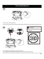
6A
6B
IMPORTANT:
Lift fan, press up on push lever.
For proper mounng, the SkyPlug and
SkyReceptacle need to be lined up in a
“+” formation.
Line up SkyPlug to SkyReceptacle mounted in ceiling.
Insert SkyPlug into SkyReceptacle (Keep push lever pushed up while inserting).

13
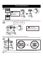
Fan Installation
Push up on fan to lock plug into receptacle (listen for locking “click”).
Once plug is fully inserted, let go of push lever while supporting fan.
Turn fan to the right (counter clockwise) to engage into slots and activate the final locking
mechanism.
“Click” sound
IMPORTANT :
SkyPlug must be fully
engaged into
SkyReceptacle.
IMPORTANT :
Push lever must be in DOWN
position once installed.
90
6D
6E
6C

7
8
9
Fan Installation
Once installed, tighten all 4 screws.
14
Reinstall the trim ring, being careful not to depress the push lever.
Install blades.

10
11
12
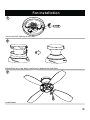
Fan Installation
Install Mounting plate.
Install LED Light kit.
15
Install shade-turn to secure.
WARNING: Make sure to fully
secure the glass shade in
place by turning the shade
clockwise (to the right) until it
is locked in place and can no
longer be rotated.
Note: Loosen 2 and remove 1
of the 3 mounting plate screws
located at the bottom of motor
assembly.
Note: Loosen 2 and
remove 1 of the 3 light
kit mounting screws on
the mounting plate.
Remove 1
Loosen 2
Remove 1
Loosen 2

16
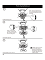
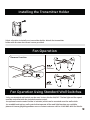
Fan Operation
Summer
Winter
Reverse Switch
Fan Operation Using Standard Wall Switches
-Only one standard wall switch can be used to turn the fan ON/OFF. The fan light and fan speed
must be controlled with the included remote control.
-An optional remote control holder is included, which can be mounted near the wall switch.
-As an additional option, wall controls that operate all fan and light function are available,
please visit www.gelightingandfans.com or contact customer service 1-866-885-4649 for details.
Reverse Function
Installing the Transmitter Holder
Select a location to install your transmitter holder. Attach the transmitter
holder with the two short wood screws provided.

17
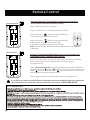
Remote Control
If you want to control multiple fans using separate remotes and do not have separate
circuit breakers for each fan, contact customer service at 1-866-885-4649.
Step 1. Shut off power to all fans at wall switch. At the circuit breaker,
reset the power (turn OFF and back ON) for the fan you are
re-programming.
Step 3. Rep
eat steps for each fan that needs re-programming.
Step 2. Within 30 seconds of resetting the power, turn wall switch back
on, switch the lock /unlock button on the back of the transmitter to
“lock ” position. Push the Sync “ ” button for about 5-10 seconds,
until the light on the fan flashes 3 times.
In Case Of Interference With Other Fans, You Can Change The
Transmitter Code To Operate This Fan Only.
Unlock Position
L
o
c
k P
o
s
i
t
i
o
n
Operate Fan Using Transmitter Code Pre-set by Factory
( Keep Switch Placed In Unlock Position )
S
t
e
p 1
. R
e
s
t
o
r
e p
o
w
e
r t
o c
e
i
l
i
ng fan.
Step 2. Install two 1.5-volt AAA batteries provided.
Step 3. Press the “ ” button located on the front
of the transmitter to opera
te the fan.
Step 4. Press the “ ” button to operate the light .
A dimmer feature is provided on the light .
Press all the way down to get maximum light .
Note: The blue light will illuminate to indicate the transmitter
is working.
FCC ID: 2AAZPFAN61T3SP1

18
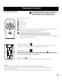
Remote Control
REMOTE FUNCTIONS
Low speed
Medium speed
Power ON/OFF
High speed
Delays the light turning off for approximately 5 seconds, enabling you to
exit your room before the light turns off completely.
Operation indicator
Controls the light and brightness setting.
Press and release the button to turn the light ON or OFF.
Press and hold the button to set the desired brightness.
The light button has an auto-resume, it will stay at the same brightness as
the last time it was turned off.
NOTE:
-To prevent damage to transmitter, remove all batteries if not used for long periods.
- Always replace the whole set of batteries at one time, taking care not to mix old and new ones, or
batteries of different types.
-Please contact your local batteries recycling center for proper battery disposal information.
“O” and “I” dim switch
The dim switch should be in the “I” position for dimming the light . Place the
switch in the “O” position to turn the dimming feature off.
“Sync” button
Allows receiver to pair with the code assigned by the transmitter.
“Lock/Unlock ” switch
NOTE: The transmitter has been preset in the unlock position. The
receiver has been preset with a common code. The transmitter can control
one or more fans with this initial setting.
IMPORTANT: If the remote control is not operating
correctly, please follow the steps on page 17 for
pairing. Use the corner of the battery cover to
press the "Sync" button for syncing function.

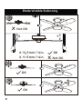
Blade Wobble Balancing
Not OK
OK
X
Y
A
B
C
D
X
X
Y 3mm / ⅛in.
Y 3mm / ⅛in.
-
-
<
>
19
Not OK
OK
OK

20
1
2
Slide down trim ring from canopy
Loosen but not remove 4 screws
3
Hold fan firmly,
turn to the left.
While holding fan, press
up on push lever to
release fan.
CAUTION :
Do not let fan fall.
Maintenance
REMOVE FAN FROM CEILING
PRODUCT MAINTENANCE
Suggestions to help maintain your fan
Because of the fan’s natural movement, some connections
may become loose. Check the support connections, brackets,
and blade attachments twice a year. Make sure they are
secure. (It is not necessary to remove fan from ceiling).
Cleaning the fan
Clean your fan periodically to help maintain its new
appearance over the years. Use only a soft brush or lint-free
cloth to avoid scratching the finish. The plating is sealed with
a lacquer to minimize discoloration or tarnishing. Do not
use water when cleaning. This could damage the motor, the
wood, or possibly cause an electrical shock.
There is no need to oil your fan. The motor has
permanently lubricated sealed ball bearings.
WARNING: Make sure the power is
turned off at the electrical panel box
before you attempt any repairs.
NOTE: To avoid personal injury or
damage to the fan and other items,
be cautious when working around
or cleaning the fan.
NOTE: Do not use water or
detergents when cleaning the fan
or fan blades. A dry dust cloth or
lightly damped cloth will be suitable
for cleaning.

21
Troubleshooting
CAUTION: Switch off power supply before carrying out any of these checks.
1.SkyPlug will not insert into SkyReceptacle:
-Add rubber washers between J-box and SkyReceptacle. See Page
10 step 3.
-Make sure you removed the disposable rubber inserts (page 11).
-Watch installation video on www.gelightingandfans.com
2.Fan will not start:
-Check main and branch circuit fuses or breakers.
-Check to make sure the wall switch is in the ON position.
-Check remote control operation.
3.Fan will not operate:
- The SkyPlug on the fan canopy should be fully inserted into
the receptacle. There are 2 levels of ball bearings on the
plug stem. The lower set of ball bearing needs to be fully
inserted into the SkyReceptacle.
-Ensure the 4mm (or combination of washers) was used
when installing the SkyReceptacle on the ceiling. ( You may
have an uneven outlet box). The SkyPlug must fully insert
into the receptacle to make the electrical connection.
-Ensure you inserted the wires correctly into the
SkyReceptacle. Black wire into L1,White wire into W,
Ground into G.
4.Fan sounds noisy:
-Make sure all motor housing screws are snug.
-Make sure the screws that attach the fan blade bracket to the motor hub is tight .
-Make sure wire nut connections are not rattling against each other or the interior wall of the switch housing.
-Allow a 24-hour “breaking-in” period. Most noises associated with a new fan disappear during this time.
-If using a ceiling fan light kit , make sure the screws securing the glassware are tight . Check that the light is also secure.
-Make sure there is a short distance from the ceiling to the canopy. It should not touch the ceiling.
-Make sure your ceiling box is secure and rubber isolator pads are used between mounting bracket and outlet box.
5.The LED will not light:
-Ensure the 2-pin connector is attached/inserted correctly.
-Ensure the power supply is turned on.
-Ensure the circuit breaker is set to “ON” position.
6.Remote control will not work:
-Ensure batteries are new and installed correctly.
-Ensure the dip switches are set correctly.
-Pair the remote control by following the instructions on page 17.
OK
OK
Not OK
Not OK
is a trademark of General Electric Company
and is under license by SQL Lighting and Fans LLC.
4400 North Point Parkway, Suite 265, Alpharetta, GA30022
For additional troubleshooting points and frequently asked questions, please visit www.gelightingandfans.com

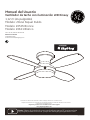
Ventilador de techo con iluminación LED Kinsey
1,12 m (44 pulgadas)
Modelo: 20444 Niquel Pulido
Modelo: 20505 Bronce
Modelo: 20611 Blanco
Manual del Usuario
NV03-20180710
120 V 60 Hz, HECHO EN CHINA
Atención al cliente
1-866-885-4649
Contacte a un electricista calificado o llame al Equipo del Servicio al Cliente Horas
de operación del Servicio al Cliente son de 9:00AM-5:00PM Hora Estándar del Este-Lunes-Viernes
Registre la garantia de su ventilador GE en nuestra página
www.gelightingandfans.com
Nota:
Videos de instalación para ventiladores marca GE con tecnología
SkyPlug se
pueden encontrar y bajar en www.gelightingandfans.com

ADVERTENCIA: Para reducir el
riesgo de lesiones personales, no
doble los brazos de las aspas
(también conocidos como bridas), al
instalar los soportes, balancear las
aspas o limpiar el ventilador. No
inserte objetos extraños entre las
aspas giratorias del ventilador.
LEA Y GUARDE ESTAS INSTRUCCIONES
Para su seguridad
Min. 7 pies/2.13 m
Min. 30 pulgadas/
76 cm
1. Para reducir el riesgo de descarga eléctrica, asegúrese de que
la electricidad se haya apagado en el disyuntor o caja de fusibles
antes de comenzar.
2. Todo el cableado debe ajustarse a la última edicion del
Código Eléctrico Nacional “ANSI/NFPA 70” y los códigos
eléctricos locales. Un electricista calificado y certificado debe
realizar la instalación eléctrica.
4. PRECAUCIÓN: Para reducir el riesgo de lesiones personales,
utilice solo los tornillos suministrados con la caja eléctrica.
5.
El peso del ventilador es 7,66 kg (16,89 lb.). La caja eléctrica y la
estructura de soporte deben montarse de forma segura y ser
capaces de soportar de forma confiable un mínimo de 15,9 kg
(35 lb).
6. El ventilador debe montarse con un espacio mínimo de 2,13 m
(7 pies) desde el borde posterior de las aspas al suelo.
7. Evite colocar objetos en el paso de las aspas.
8. Para evitar lesiones personales o daños en el ventilador y otros
elementos, tenga cuidado al trabajar cerca del ventilador o al limpiarlo.
9. No utilice agua ni detergentes al limpiar el ventilador o las
aspas. Un trapo seco o un paño ligeramente humedecido será
adecuado para la mayor parte de limpieza.
10. Después de realizar las conexiones eléctricas, los conductores
empalmados se deben voltear hacia arriba y empujarse con
cuidado dentro de la caja eléctrica. Los cables deben separarse
poniendo el conductor de puesta a tierra y el conductor de
conexión a tierra del equipo en un lado de la caja eléctrica y el
conductor energizado al otro lado de la caja eléctrica.
11. Todos los tornillos de fijación deben comprobarse y volver a
apretarse cuando sea necesario antes de la instalación.
1
12.
Este ventilador es ideal para habitaciones de hasta 144 pies
cuadrados (13,38 metros cuadrados).
3. ADVERTENCIA: para reducir el riesgo de descargas eléctricas
o incendios, no utilice este ventilador con ningún dispositivo de
estado sólido de control de velocidad del ventilador. Esto puede
dañar de forma permanente los circuitos electrónicos.
13.
Este ventilador esta diseñado para ser montado/instalado en techo plano solamente.
No monte el ventilador en un techo inclinado o abovedado.
ADVERTENCIA: Para reducir el riesgo
de incendios,
descargas elctricas o
lesiones personales, monte el
ventilador en una caja elctrica
marcada como “aceptable para el
soporte de ventiladores de 15,9 kg
(35 lb) o menos” y utilice los tornillos
de montaje suministrados con la
caja eléctrica. La mayoría de las
cajas eléctricas de uso común para
el soporte de dispositivos de
iluminación no son adecuadas para
el soporte de ventiladores y es
posible que sea necesario
reemplazarlas. Debido a la
complejidad de la instalación de
este ventilador, se recomienda que
lo instale un electricista calificado y
certificado.
NOTA: El ventilador se debe instalar
a una distancia mínima de 6 m (20
pies) de la unidad de transmisión
para una señal de transmisión
efectiva entre el transmisor y el
receptor del ventilador.
PRECAUCIÓN: No use interruptores
de pared con reguladores de
intensidad (dimmers).

2
Consejos de Seguridad
1. Antes de trabajar en un circuito, vaya al panel de servicio
principal y retire el fusible o active el disyuntor que controla
ese circuito.
2. Pegue una señal en el panel que advierta a otras personas
que se alejen del circuito mientras usted trabaja.
3. Antes de tocar cualquier cable, use un voltímetro para
asegurarse de que no esté bajo tensión.
4. Al comprobar el voltaje en un receptáculo, compruebe
ambas salidas. Cada una puede controlarse mediante un
circuito de cableado separado.
5. Al sustituir los fusibles, apague primero el cable de corriente.
Asegúrese de que sus manos y sus pies estén secos y coloque
una mano detrás de la espalda para evitar que la electricidad
haga un circuito completo a través de su pecho. Toque un
fusible del enchufe solamente por medio de su borde aislado.
6. Retire los fusibles de cartucho con un extractor de fusibles.
7. Utilice herramientas con mangos aislados y escaleras de
madera o fibra de vidrio.
8. Para proteger a los niños, coloque la cubierta de seguridad
sobre cualquier salidas no utilizada.
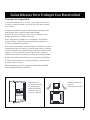
Desconecte la
corriente principal
en el disyuntor o
panel de fusibles
antes de retirar el
accesorio anterior.
Retire el accesorio
anterior.
Desconecte el cable.
5,,
PANEL
PRINCIPAL
Guías Básicas Para Trabajar Con Electricidad

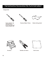
Herramientas Necesarias (No Suministradas)
3
Requerido
Destornillador de
Cabeza Plana
(Se recomienda un
Destornillador #1)
Destornillador Philips
Gafas de Seguridad
Escalera
Pelador de Cables
Paño suave

4
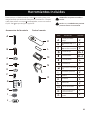
Herramientas Incluidas
Desempaque cuidadosamente e identi que cada pieza para
asegurarse de que esté todo listo para la instalación. Coloque
cada pieza sobre una super cie despejada, como una mesa o
el piso. Veri que que tenga lo siguiente:
A 2
2
1
12+1
12+1
2
L
2
B
2
1
K
1
4
1
M
ATENCIÓN: Las piezas no están a
escala.
Accessorios de ferretería Control remoto
PIEZA DESCRIPCIÓN
Tornillo para madera
(largo)
Arandela de fibra
Transmisor
Receptor (Pre-Instalado
adentro de la cubierta interior
del motor del ventilador)
Arandela plana
Casquillo plástico
Batería AAA
Tornillo de madera
(corto)
Tornillo del aspa
Kit de balanceo
Soporte de transmisor
CANTIDAD
NOTA: +1 = Cantidad extra provista
para uso futuro si se necesita
N
2
O
2
Arandela de goma (7mm)
C
Tornillo de montaje
A
C
E
L
O
B
D
K
N
F
M
+
-
G
H
I
J
1
J
Cubierta
Arandela de goma (4mm)
(Pre-ensamblado a la Receptáculo
Sky)
(Pre-ensamblado a la Receptáculo
Sky)
(Pre-ensamblado a la Receptáculo
Sky)

5
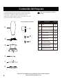
Contenido del Paquete
Cuidadosamente desempaque e identifique cada
pieza para asegurarse que tiene todo listo para la
instalación. Coloque todas las piezas en una
superficie limpia y plana como una mesa o el suelo.
Asegúrese que tiene lo siguiente:
Registre la garantia de su ventilador GE en nuestra página
www.gelightingandfans.com
X
4
S
1
1
4
W
3
Q
1
U
P
1
T
R
1
V
3
PIEZA DESCRIPCIÓN
Aspa
Plato de montaje
Tornillo de montaje del dosel
con Tubo de extension
Tornillo del juego de luz (Pre-
ensamblado a al plato de montaje)
Juego de luz LED
Ensamble del motor
Pantalla de vidrio
CANTIDAD
ATENCIÓN: Las piezas no están a
escala.
P
T
S
Q
U
V
W
R
X
Receptáculo Sky
(Pre-ensamblado a la Receptáculo Sky,
tornillo de montaje y arandela plana)
(Pre-ensamblado a la cubierta
interior del motor del ventilador)
Tornillo plato de montaje
(Pre-ensamblado a la parte
inferior) del motor del ventilador)
Accesorios de jación

6
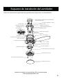
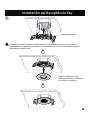
Esquema de instalación del ventilador
Registre la garantia de su ventilador GE en nuestra página
www.gelightingandfans.com
Revise las instrucciones importantes de seguridad antes de proceder con la instalación.
Caja eléctrica aceptable para ventilador
(No suministrada)
Arandela de goma
Cable negro
Tornillo de madera ( Largo)
Cable a tierra
Cable blanco neutral
Orificios del Receptáculo
Arandela plana
Tornillo de montaje
Tornillo de montaje del dosel
Aspa
Conjunto de luz LED
Campana de vidrio
Tornillo del conjunto de luz
Plato de montaje
Conjunto del motor
Anillo del dosel
Palanca de Presión
Receptáculo Sky
Receptor
Enchufe Sky
Cubierta
Arandela de fibra
Tornillo del aspa
Tornillo del plato de montaje

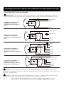
Configuraciones Típicas de Cableado del Receptáculo Sky
7
CONFIGURACIONES TÍPICAS DE CABLEADO:
Negro (Vivo)
Negro
Negro
Negro (Vivo 1)
Rojo (Vivo 2)
Blanco
Blanco
Blanco
Blanco
Blanco
Verde
Verde
Verde
IMPORTANTE: Para ventiladores con control remoto, L1 es el único terminal activo. El cable con
corriente de suministro de la casa debe insertarse en la terminal L1 para que el ventilador funcione.
Negro (Vivo)
Blanco
Verde
DIAGRAMA DE CABLEADO #1
Configuraciones Típicas de
Cableado para 1 Interruptor de
Pared.
DIAGRAMA DE CABLEADO # 2
Configuraciones Típicas de
Cableado para 2 Interruptores de
Pared.
DIAGRAMA DE CABLEADO # 3
Configuraciones Típicas de
Cableado para 2 Interruptores de
Pared.
DIAGRAMA DE CABLEADO # 4
Configuraciones Típicas de
Cableado con más de 1 cable del
mismo color en la caja eléctrica.
Conector de Cable
NOTA : Si usted no tiene una configuración de cableado estándar y tiene preguntas acerca del
cableado de su caja eléctrica, favor de contactar a un electricista calificado, o llamar a la línea de servicio al
cliente al 1-866-885-4649.
NOTA : Si usted tiene varios cables conectados juntos, adicione un cable puente y conecte el cable
puente en el terminal. Solamente un cable sencillo se puede insertar en el terminal.
Vea videos de instalación en www.gelightingandfans.com

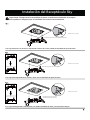
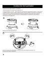
Instalación del Receptáculo Sky
Arandela de goma de 4mm (Pre-ensamblado)
Arandela de goma de 7mm
Arandela de goma de 4mm
Arandela de goma de 7mm
Arandela de goma de 7mm
Arandela de goma de 7mm
Arandela de goma de 4mm
Espacio de 0-1,5mm
Espacio de 1.5-3mm
Espacio de >3mm
>3mm
1.5-3mm
Si su caja esta al ras con el techo o empotrada a menos de 1.5mm, instale las arandelas de goma de 4mm.
Si su caja esta empotrada entre 1.5mm y 3mm, use las arandelas de goma de 7mm.
Si su caja esta empotrada a más de 3mm, use ambas arandelas de 4mm y 7mm al mismo tiempo.
8
Arandela de goma de 4mm
Arandela de goma de 4mm
Importante: Siempre use las arandelas de goma cuando este instalando el receptor.
Esto ayudara a asegurar que el ventilador se conecte correctamente.
0-1.5mm

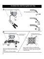
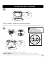
Instalación del Receptáculo Sky
9
1/2 pulgadas/12,7 mm
1
2
OK
No
OK
No
OK
Nota: Si usted no tiene una configuración
estándar en su cableado, por favor contacte
un electricista o llame a Servicio al Cliente al
1-866-885-4649.
Caja Eléctrica (no
suministrada)
Receptáculo
Sky
Vista de debajo de los
terminales del receptáculo
Sky
Inserte los cables en los terminales,
apriete los tornillos para asegurar los
cables.
Fuerza de giro 6.3 libras-pulgada.

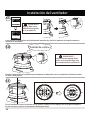
Instalación del Receptáculo Sky
10
Arandela de Goma
3
Instale la cubierta si esta
suministrada (No se suministra
con todos los modelos)
Usando la arandela de goma cuando instale los receptáculos permite una colocación
apropiada del receptáculo en el techo. Recomendamos el uso de las arandelas de goma
en todas las instalaciones.

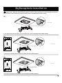
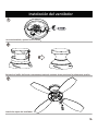
Instalación del ventilador
11
4
5
Retire los insertos de goma (afloje los cuatro tornillos de montaje levemente si es
necesario) del toldo y deséchelos.
Deslice el anillo del borde del dosel.
Hay dos opciones para instalar su ventilador:
Preinstalado
Receptor
1) Para ensamblar en el techo siga los pasos 4 -12
2) Para ensamblar en el piso – siga los pasos 9-12 para primero ensamblar las aspas y el kit de luz al
ventilador mientras esta en el piso y luego los pasos 4-8 para instalar el ventilador ensamblado al
techo. TIP: Primero practique instalando el motor del ventilador al techo (Paso 6A-E) antes de
ensamblar las aspas y el kit de luz al motor. Para desinstalar el ventilador del techo siga las
instrucciones en la página 20.

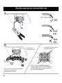
12
6A
6B
Levante el ventilador y presione hacia arriba la palanca de empuje.
Alinee Skyplug con el SkyReceptacle montado en el techo.
Introduzca Skyplug en el SkyReceptacle (mantenga la palanca de empuje hacia arriba
durante la inserción).
Instalación del ventilador
Para un montaje correcto,
SkyPlug y SkyReceptacle deben
estar alineados en forma de “+”.
IMPORTANTE:

13
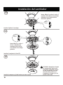
Empuje hacia arriba el ventilador para bloquear el dispositivo en el receptáculo (hasta escuchar
el «clic» de bloqueo).
Una vez que el dispositivo esté totalmente introducido, suelte la palanca de empuje mientras
sostiene el ventilador.
Gire el ventilador hacia la derecha (en el sentido contrario a las agujas del reloj) para acoplarlo
en las ranuras y activar el mecanismo de bloqueo final.
Sonido de «clic»
IMPORTANTE:
Skyplug debe estar
totalmente acoplado
en el receptáculo
IMPORTANTE :
La palanca de empuje debe
estar en la posición baja una
vez completada la instalación
90
6D
6E
6C
Instalación del ventilador

7
8
9
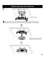
Instalación del ventilador
Una vez instalado, apriete los 4 tornillos.
14
Reinstale el anillo del borde nuevamente, teniendo cuidado de no presionar la palanca de presión.
Instale las aspas del ventilador.

10
11
12
Instalación del ventilador
Instale el plato de montaje.
Instale el conjunto de luz LED.
15
Instale la campana, gírela hasta que este segura.
CUIDADO: Asegúrese de que
la campana de vidrio este
sostenida girándola a favor
de las manecillas del reloj
(a la derecho) hasta que
tranque en el lugar y no se
pueda rotar mas.
Nota: Afloje 2 y retire 1 de los 3
tornillos de la placa de montaje
ubicados en la parte inferior
del motor primero.
Retire 1
Afloje 2
Nota: Afloje 2 y retire 1
de los 3 tornillos de
montaje del kit de luz
en la placa de montaje
primero.
Retire 1
Afloje 2

16
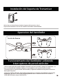
Funcionamiento del Ventilador utilizando
interruptores de pared estándar
-Solo un interruptor de pared estándar se puede usar para prender y apagar el ventilador. La
luz y la velocidad del ventilador deben ser controladas con el control remoto incluido.
-Una base para el control remoto está incluida, es opcional instálarla en la pared cerca de su
interruptor de pared.
-Como una opción adicional, interruptores de pared que controlan el ventilador y la luz están
disponibles, por favor visite www.gelightingandfans.com o contacte Servicio al Cliente al
1-866-885-4649 para mayor información.
Verano
Invierno
Función de Reversa
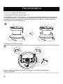
Operacion del Ventilador
Seleccione una ubicación para instalar el soporte del transmisor. Fije el
soporte del transmisor con los dos tornillos de madera suministrados.
Interruptor de Reversa
Instalación del Soporte de Transmisor

17
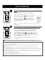
Control Remoto
Paso 3.Repita los pasos para cada ventilador que necesita
re - programación.
En Caso de Interferencia con Otros Ventiladores Usted Puede Cambiar
el Código del Transmisor Para Operar Este Ventilador Solamente.
Posición de bloqueo
Opere el Ventilador Usando el Código de Transmisión Pre Instalado de
Fábrica ( Mantener el interruptor colocado en posición de desbloqueo )
Nota: La luz azul se iluminará para indicar que el transmisor está
funcionando.
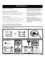
Paso 1. Restablezca la electricidad del ventilador.
Paso 4. Presione el botón “ ” para operar la luz.
Esta luz viene equipada con regulacion de intensidad
ajustable. Presione y sostenga el boton para ajustar
la intensidad deseada.
Paso 2. Instale dos baterías AAA de 1,5 -vatios provistas.
Paso 3. Presione el botón “ ” localizado en la parte
delantera del transmisor para operar el ventilador.
Paso 2. Dentro de los 30 segundos de restablecer la energía,
cambie el botón de bloqueo / desbloqueo en la parte
posterior del transmisor para bloquear la posición. Presione el
botón Sync durante aproximadamente 5-10 segundos, hasta
que la luz del ventilador parpadee 3 veces.
Paso 1. Primero apague la alimentación de poder de otros
ventiladores, restablezca la alimentación del ventilador en el
interruptor de circuito (apague y encienda el interruptor).
Si desea controlar múltiples ventiladores utilizando controles remotos separados y no tiene
circuitos separados para cada ventilador, comuníquese con el servicio al cliente al 1-866-885-4649.
FCC ID: 2AAZPFAN61T3SP1
Este artículo cumple con la parte 15 de las Reglas FCC. Su operación esta sujeta a las siguientes dos condiciones:
1. Este artículo no debe causar interferencia dañina.
2 . Este articulo deberá aceptar cualquier interferencia recibida, incluyendo interferencia que pueda causar un funcionamiento no deseado.
CUIDADO: Cualquier cambio o modificaciones no aprobadas por el grupo responsable del cumplimiento puede cancelar la autoridad del
usuario de operar este artículo.
NOTA: Este articulo ha sido probado y está en cumplimiento con los límites de la Clase B Digital que sigue la parte 15 de las Reglas FCC.
Estos límites están designados para proveer protección razonable contra cualquier interferencia dañina en una instalación residencial. Este articulo
genera, usa y puede irradiar energía de frecuencia radial y, si no está instalado y en uso de acuerdo a las instrucciones, puede causar interferencia
dañina a las comunicaciones radiales.
Sin embargo, no hay garantía que la interferencia no ocurrirá en una instalación particular. Si este artículo, causara interferencia dañina a recepciones
radiales o televisivas, las cuales pueden estar determinadas apagando o encendiendo el equipo, el usuario es requerido a tratar de corregir la
interferencia usando una de las siguientes soluciones.
- Reoriente o coloque en diferente posición la antena del receptor.
- Incremente la separación entre el equipo y el receptor.
- Conecte el equipo en un tomacorrientes o en un circuito diferente al cual el receptor está conectado.
- Consulte con el proveedor o un técnico de radio / TV para asistencia adicional.
Posición de desbloqueo

18
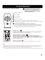
Control Remoto
FUNCIONES DEL CONTROL REMOTO
IMPORTANTE: Si el control remoto no funciona
correctamente, favor de seguir las instrucciones
en la página 17 para el emparejamiento del
interruptor. Use la esquina de la cubierta de las
baterías para presionar el botón "Sync" para la
función de emparejamiento.
Velocidad Baja
Velocidad Media
Encendido / Apagado
Velocidad Alta
Demora que la luz se apague por aproximadamente 5 segundos,
permitiéndole salir de la habitación antes que la luz se apague completamente.
Indicador de Operación
Controla la luz y la brillantez.
Presione y suelte el botón para encender o apagar la luz.
Presione y mantenga presionado para seleccionar la brillantez deseada.
El botón para la luz tiene una función automática de memoria, se mantendrá
en la misma intensidad que fue seleccionada la última vez.
Interruptor "
o
" e "I"
Para este ventilador, este interruptor debe estar en la posición "I", para que permita
la regulación de la luz. Coloque el interruptor en la posición "o
" para desactivar el
regulador de la intensidad de la luz si así lo desea.
Botón de sincronización
Este botón permite al receptor acoplarse con el código asignado al transmisor.
Interruptor de Bloqueo / desbloqueo
NOTA: Para su mayor comodidad, el transmisor ha sido preajustado y se
encuentra en la posición de desbloqueo . El receptor ha sido preestablecido con
un código común. El transmisor puede controlar uno o más ventiladores con esta
misma configuración inicial.
Nota :
-
Para prevenir que el cotrol remoto se dañe, retire las baterías si no las va a usar por largos períodos de tiempo.
- Remplace las baterías a la vez - siempre remplace el juego completo de las baterías al mismo tiempo, con
cuidado de no juntar baterías nuevas con las viejas, o baterías de diferentes tipos.
- Favor de contactar el centro local de reciclaje para obtener la información apropiada para desechar las baterías.

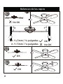
OK
No OK
A
B
C
D
X
X
Y 3mm / ⅛ pulgadas
Y 3mm / ⅛ pulgadas
-
-
<
>
19
No OK
OK
OK
X
Y
Balanceo de las aspas

20
1
Retire el anillo del borde del dosel
2
Afloje, pero no retire los 4 tornillos
3
Retirando el ventilador del techo
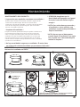
Mantenimiento
MANTENIMIENTO DEL PRODUCTO
* Sugerencias para ayudarle a mantener su ventilador *
Producto del movimiento natural del ventilador, algunas de las
conexiones se podrán aflojar. Revise los suportes de las
conexiones, soportes del ventilador y accesorios de las aspas dos
veces al año. Asegúrese que estén seguros. (No es necesario
remover el ventilador del techo).
* Limpieza del ventilador *
Limpie su ventilador periódicamente para ayudar a mantener su
nueva apariencia al pasar de los años. Use solo una brocha
suave o un paño sin pelusas para evitar que el terminado del
ventilador se arañe. El acabado este sellado con una laca que
minimiza la descoloración o la perdida de lustre. No use agua
cuando realice la limpieza. Esto podrá dañar el motor, la madera,
o producir un corte eléctrico.
*
No hay necesidad de engrasar su ventilador. El motor tiene
un sistema de rodamiento sellado que permanece lubricado. *
*
ATENCION: Asegúrese que la
electricidad está apagada en el panel
de control antes de realizar ningún
arreglo.*
*
NOTA: Para evitar danos personales y
al ventilador u otros artículos, sea
cuidadoso cuando trabaje alrededor o
limpie el ventilador *
*
NOTA: No use agua ni detergentes
cuando limpie el ventilador o las aspas.
Use un paño seco o humedecido para
realizar la limpieza. *
Sostenga el ventilador firmem-
ente y gírelo hacia la izquierda
CUIDADO: No
deje caer el
ventilador
Mientras sostiene el ventilador, presione hacia arriba la
palanca de presión para retirar el ventilador.

21
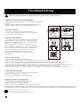
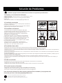
Solución de Problemas
CUIDADO: Apague la electricidad antes de realizar los siguientes procedimientos
2.
El ventilador no enciende:
-Revise los fusibles de circuitos e interruptores automáticos
principales o periféricos.
-Revise que el interruptor está en la posición de encendido.
-Revise las operaciones del control remoto.
3.
El ventilador no funciona
- El enchufe Sky en el dosel del ventilador debe estar
completamente insertado dentro del receptáculo. Hay dos
niveles de rodamientos en la espiga del enchufe. El
rodamiento de abajo tiene que estar completamente
insertado en el receptáculo Sky.
-Asegúrese que 4mm ( o la combinación de arandelas)
hayan sido usadas cuando se realizó la instalación del
receptáculo Sky en el techo. (Usted puede que tenga una
caja eléctrica dispareja). El enchufe Sky debe estar
completamente insertado en el receptáculo para realizar
las conexiones eléctricas.
-Asegúrese que los cables estén completamente
insertados en el receptáculo Sky, Cable negro en el L1.
Cable blanco en el W. Cable a tierra en el G.
4.
El ventilador hace ruido:
-Asegúrese que todos los tornillos de la cubierta del motor están apretados.
-Asegúrese que los tornillos que adjuntan los brazos de las aspas al ventilador estén apretados.
-Asegúrese que las conexiones de los extremos de los cables no hagan contacto entre ellas o con el interior de la pared de la
cubierta del interruptor.
-Permita un periodo de 24 horas de “uso”. La mayoría de los ruidos asociados con un ventilador nuevo desaparecen durante
este periodo de tiempo.
-Si usa un ventilador con juego de luz, asegúrese que los tornillos que aseguran la pantalla estén apretados, verifique que los
bombillos también estén asegurados.
-Asegurese que hay una pequeña distancia entre el techo y el dosel. El dosel no deberá tocar el techo.
-Asegúrese que la caja eléctrica está asegurada con una insolación de goma que se usan entre el soporte de montaje y la
caja eléctrica.
5.
El LED no enciende:
-
Asegúrese que los conectores de 2 pines estén adheridos / insertados correctamente.
-Asegúrese que la electricidad este encendida.
-Asegúrese que los juegos de interruptores automáticos estén en la posición de encendido.
6.
El control remoto no funciona:
-
Asegúrese que las baterías están nuevas e insertadas correctamente.
-Asegúrese que los interruptores dip estén programados correctamente.
-Sincronice el control remoto siguiendo las instrucciones en la página 17.
OK
OK
No OK
No OK
es una marca registrada de General Electric Company
y esta bajo la licencia de SQL Lighting and Fans, LLC
4400 North Point Parkway, Suite 265, Alpharetta, GA 30022
1.EL Skyplug no se insertará en el Receptor:
-Agregue arandelas de goma entre el J-box y el Receptor. Vea la
página 10 paso 3.
-Asegúrese de quitar las inserciones de goma desechables
(página 11).
-Ver video de instalación en www.gelightingandfans.com
Para información adicional en cómo resolver problemas de su ventilador y las preguntas más
frecuentes, por favor visite www.gelightingandfans.com
-
 1
1
-
 2
2
-
 3
3
-
 4
4
-
 5
5
-
 6
6
-
 7
7
-
 8
8
-
 9
9
-
 10
10
-
 11
11
-
 12
12
-
 13
13
-
 14
14
-
 15
15
-
 16
16
-
 17
17
-
 18
18
-
 19
19
-
 20
20
-
 21
21
-
 22
22
-
 23
23
-
 24
24
-
 25
25
-
 26
26
-
 27
27
-
 28
28
-
 29
29
-
 30
30
-
 31
31
-
 32
32
-
 33
33
-
 34
34
-
 35
35
-
 36
36
-
 37
37
-
 38
38
-
 39
39
-
 40
40
-
 41
41
-
 42
42
-
 43
43
-
 44
44


GE 20611 Instrucciones de operación
- Categoría
- Ventiladores domésticos
- Tipo
- Instrucciones de operación
En otros idiomas
- English: GE 20611 Operating instructions
Documentos relacionados
Otros documentos
-
Fanimation Brewmaster FP1280 El manual del propietario
-
-
-
Progress Lighting P2564-3030K Guía de instalación
-
-