
Step - T

AVVERTENZE PER L’INSTALLATORE
OBBLIGHI GENERALI PER LA SICUREZZA
1) ATTENZIONE! È importante per la sicurezza delle persone seguire attentamente tutta l’istruzione.
Una errata installazione o un errato uso del prodotto può portare a gravi danni alle persone.
2) Leggere attentamente le istruzioni prima di iniziare l’installazione del prodotto.
3) I materiali dell’imballaggio (plastica, polistirolo, ecc.) non devono essere lasciati alla portata
dei bambini in quanto potenziali fonti di pericolo.
4) Conservare le istruzioni per riferimenti futuri.
5) Questo prodotto è stato progettato e costruito esclusivamente per l’utilizzo indicato in questa
documentazione. Qualsiasi altro utilizzo non espressamente indicato potrebbe pregiudicare
l’integrità del prodotto e/o rappresentare fonte di pericolo.
6) GENIUS declina qualsiasi responsabilità derivata dall’uso improprio o diverso da quello per cui
l’automatismo è destinato.
7) Non installare l’apparecchio in atmosfera esplosiva: la presenza di gas o fumi infiammabili
costituisce un grave pericolo per la sicurezza.
8) Gli elementi costruttivi meccanici devono essere in accordo con quanto stabilito dalle Norme
EN 12604 e EN 12605.
Per i Paesi extra-CEE, oltre ai riferimenti normativi nazionali, per ottenere un livello di sicurezza
adeguato, devono essere seguite le Norme sopra riportate.
9) GENIUS non è responsabile dell’inosservanza della Buona Tecnica nella costruzione delle
chiusure da motorizzare, nonché delle deformazioni che dovessero intervenire nell’utilizzo.
10) L’installazione deve essere effettuata nell’osservanza delle Norme EN 12453 e EN 12445. Il livello
di sicurezza dell’automazione deve essere C+D.
11) Prima di effettuare qualsiasi intervento sull’impianto, togliere l’alimentazione elettrica e scollegare
le batterie.
12) Prevedere sulla rete di alimentazione dell’automazione un interruttore onnipolare con distanza
d’apertura dei contatti uguale o superiore a 3 mm. È consigliabile l’uso di un magnetotermico
da 6A con interruzione onnipolare.
13) Verificare che a monte dell’impianto vi sia un interruttore differenziale con soglia da 0,03 A.
14) Verificare che l’impianto di terra sia realizzato a regola d’arte e collegarvi le parti metalliche
della chiusura.
15) L’automazione dispone di una sicurezza intrinseca antischiacciamento costituita da un control-
lo di coppia. E' comunque necessario verificarne la sogli di intervento secondo quanto
previsto dalle Norme indicate al punto 10.
16) I dispositivi di sicurezza (norma EN 12978) permettono di proteggere eventuali aree di pericolo
da Rischi meccanici di movimento, come ad Es. schiacciamento, convogliamento,
cesoiamento.
17) Per ogni impianto è consigliato l’utilizzo di almeno una segnalazione luminosa nonché di un
cartello di segnalazione fissato adeguatamente sulla struttura dell’infisso, oltre ai dispositivi citati
al punto “16”.
18) GENIUS declina ogni responsabilità ai fini della sicurezza e del buon funzionamento dell’auto-
mazione, in caso vengano utilizzati componenti dell’impianto non di produzione GENIUS.
19) Per la manutenzione utilizzare esclusivamente parti originali GENIUS.
20) Non eseguire alcuna modifica sui componenti facenti parte del sistema d’automazione.
21) L’installatore deve fornire tutte le informazioni relative al funzionamento manuale del sistema in
caso di emergenza e consegnare all’Utente utilizzatore dell’impianto il libretto d’avvertenze
allegato al prodotto.
22) Non permettere ai bambini o persone di sostare nelle vicinanze del prodotto durante il
funzionamento.
23) Tenere fuori dalla portata dei bambini radiocomandi o qualsiasi altro datore di impulso, per
evitare che l’automazione possa essere azionata involontariamente.
24) Il transito tra le ante deve avvenire solo a cancello completamente aperto.
25) L’Utente utilizzatore deve astenersi da qualsiasi tentativo di riparazione o d’intervento diretto e
rivolgersi solo a personale qualificato.
26) Non mettere in corto circuito i poli delle batterie e non tentare di ricaricarle con alimentatori
diversi dalle schede Master o Slave.
27) Non gettare le batterie esauste nei rifiuti ma smaltirle utilizzando gli appositi contenitori per
consentirne il riciclaggio. I costi di smaltimento sono già stati pagati dalla casa costruttrice.
28) Tutto quello che non è previsto espressamente in queste istruzioni non è permesso
IMPORTANT NOTICE FOR THE INSTALLER
GENERAL SAFETY REGULATIONS
1) ATTENTION! To ensure the safety of people, it is important that you read all the following
instructions. Incorrect installation or incorrect use of the product could cause serious harm to
people.
2) Carefully read the instructions before beginning to install the product.
3) Do not leave packing materials (plastic, polystyrene, etc.) within reach of children as such
materials are potential sources of danger.
4) Store these instructions for future reference.
5) This product was designed and built strictly for the use indicated in this documentation. Any other
use, not expressly indicated here, could compromise the good condition/operation of the
product and/or be a source of danger.
6) GENIUS declines all liability caused by improper use or use other than that for which the
automated system was intended.
7) Do not install the equipment in an explosive atmosphere: the presence of inflammable gas or
fumes is a serious danger to safety.
8) The mechanical parts must conform to the provisions of Standards EN 12604 and EN 12605.
For non-EU countries, to obtain an adequate level of safety, the Standards mentioned above
must be observed, in addition to national legal regulations.
9) GENIUS is not responsible for failure to observe Good Technique in the construction of the
closing elements to be motorised, or for any deformation that may occur during use.
10) The installation must conform to Standards EN 12453 and EN 12445. The safety level of the
automated system must be C+D.
11) Before attempting any job on the system, cut out electrical power and disconnect the
batteries.
12) The mains power supply of the automated system must be fitted with an all-pole switch with
contact opening distance of 3mm or greater. Use of a 6A thermal breaker with all-pole circuit
break is recommended.
13) Make sure that a differential switch with threshold of 0.03 A is fitted upstream of the system.
14) Make sure that the earthing system is perfectly constructed, and connect metal parts of the
means of the closure to it.
15) The automated system is supplied with an intrinsic anti-crushing safety device consisting of a
torque control. Nevertheless, its tripping threshold must be checked as specified in the
Standards indicated at point 10.
CONSIGNES POUR L'INSTALLATEUR
RÈGLES DE SÉCURITÉ
1) ATTENTION! Il est important, pour la sécurité des personnes, de suivre à la lettre toutes les
instructions. Une installation erronée ou un usage erroné du produit peut entraîner de graves
conséquences pour les personnes.
2) Lire attentivement les instructions avant d'installer le produit.
3) Les matériaux d'emballage (matière plastique, polystyrène, etc.) ne doivent pas être laissés
à la portée des enfants car ils constituent des sources potentielles de danger.
4) Conserver les instructions pour les références futures.
5) Ce produit a été conçu et construit exclusivement pour l'usage indiqué dans cette
documentation. Toute autre utilisation non expressément indiquée pourrait compromettre
l'intégrité du produit et/ou représenter une source de danger.
6) GENIUS décline toute responsabilité qui dériverait d'usage impropre ou différent de celui
auquel l'automatisme est destiné.
7) Ne pas installer l'appareil dans une atmosphère explosive: la présence de gaz ou de fumées
inflammables constitue un grave danger pour la sécurité.
8) Les composants mécaniques doivent répondre aux prescriptions des Normes EN 12604 et EN
12605.
Pour les Pays extra-CEE, l'obtention d'un niveau de sécurité approprié exige non seulement le
respect des normes nationales, mais également le respect des Normes susmentionnées.
9) GENIUS n'est pas responsable du non-respect de la Bonne Technique dans la construction des
fermetures à motoriser, ni des déformations qui pourraient intervenir lors de l'utilisation.
10) L'installation doit être effectuée conformément aux Normes EN 12453 et EN 12445. Le niveau de
sécurité de l'automatisme doit être C+D.
11) Couper l'alimentation électrique et déconnecter la batterie avant toute intervention sur
l'installation.
12) Prévoir, sur le secteur d'alimentation de l'automatisme, un interrupteur omnipolaire avec une
distance d'ouverture des contacts égale ou supérieure à 3 mm. On recommande d'utiliser un
magnétothermique de 6A avec interruption omnipolaire.
13) Vérifier qu'il y ait, en amont de l'installation, un interrupteur différentiel avec un seuil de 0,03 A.
14) Vérifier que la mise à terre est réalisée selon les règles de l'art et y connecter les pièces
métalliques de la fermeture.
15) L'automatisme dispose d'une sécurité intrinsèque anti-écrasement, formée d'un contrôle du
couple. Il est toutefois nécessaire d'en vérifier le seuil d'intervention suivant les prescriptions des
Normes indiquées au point 10.
16) Les dispositifs de sécurité (norme EN 12978) permettent de protéger des zones éventuellement
dangereuses contre les Risques mécaniques du mouvement, comme l'écrasement,
l'acheminement, le cisaillement.
17) On recommande que toute installation soit doté au moins d'une signalisation lumineuse, d'un
panneau de signalisation fixé, de manière appropriée, sur la structure de la fermeture, ainsi que
des dispositifs cités au point “16”.
18) GENIUS décline toute responsabilité quant à la sécurité et au bon fonctionnement de
l'automatisme si les composants utilisés dans l'installation n'appartiennent pas à la production
GENIUS.
19) Utiliser exclusivement, pour l'entretien, des pièces GENIUS originales.
20) Ne jamais modifier les composants faisant partie du système d'automatisme.
21) L'installateur doit fournir toutes les informations relatives au fonctionnement manuel du système
en cas d'urgence et remettre à l'Usager qui utilise l'installation les "Instructions pour l'Usager"
fournies avec le produit.
22) Interdire aux enfants ou aux tiers de stationner près du produit durant le fonctionnement.
23) Eloigner de la portée des enfants les radiocommandes ou tout autre générateur d'impulsions,
pour éviter tout actionnement involontaire de l'automatisme.
24) Le transit entre les vantaux ne doit avoir lieu que lorsque le portail est complètement ouvert.
25) L'Usager qui utilise l'installation doit éviter toute tentative de réparation ou d'intervention directe
et s'adresser uniquement à un personnel qualifié.
26) Ne pas mettre en court-circuit les pôles des batteries et ne pas tenter de les recharger avec
d'autres platines d'alimentation que les platines Maître ou Esclave.
27) Ne pas jeter les batteries épuisées à la poubelle, mais les éliminer dans les conteneurs
spécifiques pour le recyclage. Les coûts d'élimination des déchets ont déjà été payés par le
constructeur.
28) Tout ce qui n'est pas prévu expressément dans ces instructions est interdit.
16) The safety devices (EN 12978 standard) protect any danger areas against mechanical
movement Risks, such as crushing, dragging, and shearing.
17) Use of at least one indicator-light is recommended for every system, as well as a warning sign
adequately secured to the frame structure, in addition to the devices mentioned at point “16”.
18) GENIUS declines all liability as concerns safety and efficient operation of the automated
system, if system components not produced by GENIUS are used.
19) For maintenance, strictly use original parts by GENIUS.
20) Do not in any way modify the components of the automated system.
21) The installer shall supply all information concerning manual operation of the system in case of
an emergency, and shall hand over to the user the warnings handbook supplied with the
product.
22) Do not allow children or adults to stay near the product while it is operating.
23) Keep remote controls or other pulse generators away from children, to prevent the automated
system from being activated involuntarily.
24) Transit through the leaves is allowed only when the gate is fully open.
25) The user must not attempt any kind of repair or direct action whatever and contact qualified
personnel only.
26) Do not short-circuit the poles of the batteries and do not try to recharge the batteries with power
supply units other than Master or Slave cards.
27) Do not throw exhausted batteries into containers for other waste but dispose of them in the
appropriate containers to enable them to be recycled. Disposal costs have already been
paid for by the manufacturer.
28) Anything not expressly specified in these instructions is not permitted.

1
ITALIANO
olledoMT-PETS
enoizatnemilA cdV21
)W(atibrossaelanimonaznetoP 84
).nim/m(xamotouvaeraenilàticoleV 51
)N(acita
tsazroF 051
aciracairettabaivitucesnocilciC 03
airettaballedaciraciridopmeT otiugeseolcicingorep'2~
)C°(etn
eibmaarutarepmeT 55+÷02-
)gK(erotarepooseP 3,5
enoizetorpidodarG 44PI
)m(atnaxamazzehgnuL 5
)gK(atnaxamoseP 00
3
)mm(PxHxLerotarepoorbmognI 2.giFidev
Fig.01
Fig.02
• quote in mm
Automazione STEP-T
Le presenti istruzioni sono valide per il seguente modello:
GENIUS STEP-T
L’automazione STEP-T, consente di automatizzare cancelli scor-
revoli residenziali con ante fino a 5 m di lunghezza e 300 Kg di
peso.
È costituita da un motoriduttore elettromeccanico irreversibile,
alimentato a 12 Vdc tramite trasformatore toroidale e scheda
alimentazione. Alloggiata all'interno del STEP-T vi è un'apparec-
chiatura elettronica programmabile che permette di impostare
le logiche di funzionamento, i tempi di lavoro (in auto-apprendi-
mento) e di pausa, la velocità del cancello, la sensibilità dell'an-
tischiacciamento e l'ampiezza dell'apertura parziale.
Il sistema irreversibile garantisce il blocco meccanico del cancello
quando il motore non è in funzione. Uno sblocco manuale rende
manovrabile il cancello in caso di disservizio.
L'automazione STEP-T è stata progettata e costruita per controllare
l’accesso veicolare. Evitare qualsiasi altro diverso utilizzo.
1. DESCRIZIONE E CARATTERISTICHE TECNICHE
Tab. 1 - Caratteristiche tecniche operatore STEP-T
La protezione termica software permette di eseguire 30 cicli con-
secutivi. Il tempo di recupero è di 2 minuti per ogni ciclo eseguito.
1) Operatore STEP-T
2) Fianchetti laterali di protezione
3) Pignone
4) Sblocco manuale
5) Piastra di fondazione
6) Scheda elettronica
7) Trasformatore toroidale
8) Supporto trasformatore e scheda alimentazione
9) Scheda alimentazione
10) Carter paramani
11) Antenna (Optional)
2. DIMENSIONI
1
2
3
4
5
6
7
8
9
10
11

2
ITALIANO
2x1,5 mm + (230Vac)
2
Fig.03
Fig.04
Fig.05
175,5
0
÷
50
90
°
1
Fig.06
Fig.07
0
÷
50
90,5
90
°
1
1) Operatore con apparecchiatura
2) Fotocellule
3) Pulsante a chiave
4) Lampeggiatore
5) Ricevente radio
*Utilizzare le quote in base al tipo di cremagliera
Cremagliera zincata 30x6 = 36,5mm
Cremagliera zincata 30x12 = 39,5mm
Cremagliera in nylon 30x20 = 41,5mm
Dir. chiusura
*Utilizzare le quote in base al tipo di cremagliera
Cremagliera zincata 30x6 = 36,5mm
Cremagliera zincata 30x12 = 39,5mm
Cremagliera in nylon 30x20 = 41,5mm
Dir. chiusura
3. DESCRIZIONE IMPIANTO - Predisposizioni elettriche
(impianto standard)
Note:
1) Per la messa in opera dei cavi elettrici utilizzare adeguati tubi
rigidi e/o flessibili.
2) Per evitare qualsiasi interferenza separare sempre i cavi di
collegamento a bassa tensione da quello di alimentazione a
230 Vac.
4. INSTALLAZIONE DELL'AUTOMAZIONE
4.1. Verifiche preliminari
Per la sicurezza e per un corretto funzionamento dell’automazio-
ne, verificare l’esistenza dei seguenti requisiti:
• La struttura del cancello deve essere idonea per essere auto-
matizzata. In particolare verificare che sia sufficientemente ro-
busta e rigida e che dimensioni e massa siano conformi a quelle
indicate nelle caratteristiche tecniche.
• Verificare che non vi siano pendenze nello scorrimento del can-
cello.
• Verificare il movimento regolare e uniforme del cancello, privo
di attriti irregolari durante tutta la corsa.
• Le caratteristiche del terreno devono garantire una sufficiente
tenuta dei tasselli di fissaggio della piastra di fondazione.
• Verificare la presenza di una guida superiore e degli arresti
meccanici di finecorsa.
• Rimuovere eventuali serrature e chiavistelli.
Si raccomanda di effettuare gli eventuali interventi fabbrili prima
d'installare l'automazione.
4.2. Preparazione piastra di fondazione
• Inserire nei 4 fori quadrati della piastra i 4 dadi in gabbia in
dotazione come da Fig. 4.
4.3. Fissaggio piastra di fondazione
1) La piastra di fondazione deve essere posizionata come da Fig.
5 (chiusura destra) o Fig. 6 (chiusura sinistra) per garantire il
corretto ingranamento tra il pignone e la cremagliera.
2) Fissare la piastra di fondazione a pavimento utilizzando ade-
guati tasselli (Fig. 7) prevedendo una o più guaine per il pas-
saggio dei cavi elettrici attraverso la piastra (Figg. 5-6 Rif. 1)
Verificare la perfetta orizzontalità della piastra con una livella.

3
ITALIANO
Fig.09
Fig.08
Fig.10
Fig.11
A
B
Fig.12
* Utilizzare le quote in base al tipo di cremagliera
Cremagliera zincata 30x6 ! A = 46,5mm e B =146mm
Cremagliera zincata 30x12 ! A = 49,5mm e B =146mm
Cremagliera in nylon 30x20 ! A = 51,5mm e B =112,5mm
4.4. Posizionamento operatore
• Predisporre i cavi elettrici per il collegamento degli accessori e
l'alimentazione elettrica come da Fig. 3. Per effettuare agevol-
mente i collegamenti fare fuoriuscire i cavi della lunghezza ne-
cessaria per la connessione in morsettiera, al trasformatore e
alla scheda di decodifica (se presenti).
• Posizionare l'operatore sulla piastra utilizzando le viti in dotazio-
ne come da Fig. 8.
4.5. Regolazione operatore
• Registrare la distanza dell'operatore dal cancello facendo rife-
rimento a Fig. 9.
4.6. Fissaggio operatore
• Fissare provvisoriamente l'operatore impuntando le viti come
da Fig. 10.
4.7. Sblocco dell'operatore
Predisporre l'operatore per il funzionamento manuale come indi-
cato di seguito:
• Aprire lo sportello di protezione utilizzando una moneta.
• Estrarre la chiave in dotazione alloggiata all'interno dello spor-
tello; inserirla nell'apposito sistema di sblocco e ruotarla in senso
orario fino alla battuta meccanica (Fig. 11).
4.8 Montaggio della cremagliera
4.8.1. Cremagliera di acciaio a saldare (Fig. 12)
1) Montare tre nottolini filettati sull'elemento della cremagliera
posizionandoli nella parte superiore dell'asola. In tale modo il
gioco sull'asola consentirà nel tempo le eventuali regolazioni.
2) Portare manualmente l'anta in posizione di chiusura.
3) Appoggiare sul pignone il primo pezzo di cremagliera a livello
e saldare il nottolino filettato sul cancello come indicato in Fig.
15.
4) Muovere manualmente il cancello, verificando che la crema-
gliera sia in appoggio sul pignone e saldare il secondo e il terzo
nottolino.
5) Accostare un altro elemento di cremagliera al precedente
utilizzando, per mettere in fase la dentatura dei due elementi,
un pezzo di cremagliera come indicato in Fig. 16 rif.1.
6) Muovere manualmente il cancello e saldare i tre nottolini filet-
tati proseguendo fino alla copertura completa del cancello
4.8.2. Cremagliera di acciaio ad avvitare (Fig. 13)
1) Portare manualmente l'anta in posizione di chiusura.
2) Appoggiare sul pignone il primo pezzo di cremagliera a livello
ed interporre il distanziale tra cremagliera e cancello, posizio-
nandolo nella parte superiore dell'asola.
3) Segnare il punto di foratura sul cancello. Forare ø 6,5 mm e
filettare con maschi M8 mm. Avvitare il bullone.
4) Muovere manualmente il cancello, verificando che la crema-
gliera sia in appoggio sul pignone e ripetere le operazioni del
punto 3.
5) Accostare un altro elemento di cremagliera al precedente
utilizzando, per mettere in fase la dentatura dei due elementi,
un pezzo di cremagliera come indicato in Fig. 16 rif.1.
6) Muovere manualmente il cancello e procedere nelle opera-
zioni di fissaggio come per il primo elemento, proseguendo fino
alla copertura completa del cancello.

4
ITALIANO
1
1
.
5
m
m
Fig.13
Fig.14
Fig.16
Fig.15
Fig.17
4.8.3. Cremagliera di nylon ad avvitare (Fig. 14)
1) Portare manualmente l'anta in posizione di chiusura.
2) Appoggiare sul pignone il primo pezzo di cremagliera a livello
e segnare il punto di foratura sul cancello; forare con punta ø
4mm ed avvitare la vite autofilettante 6x20 mm con relativa
piastrina di rinforzo.
3) Muovere manualmente il cancello, verificando che la crema-
gliera sia in appoggio sul pignone e ripetere le operazioni al
punto 2.
4) Accostare un altro elemento di cremagliera al precedente
utilizzando, per mettere in fase la dentatura dei due elementi,
un pezzo di cremagliera come indicato in Fig. 16 rif.1.
5) Muovere manualmente il cancello e procedere nelle opera-
zioni di fissaggio come per il primo elemento, proseguendo fino
alla copertura completa del cancello.
Note sull'installazione della cremagliera
• Verificare che durante la corsa del cancello tutti gli elementi
della cremagliera ingranino correttamente con il pignone.
• Non saldare assolutamente gli elementi della cremagliera né ai
distanziali né tra di loro.
• Terminata l'installazione della cremagliera, regolare la distanza
tra i denti del pignone e la gola della cremagliera verificando
che la distanza sia di 1,5 mm. (Fig. 17) per tutta la corsa, sfrut-
tando le asole della cremagliera.
• Verificare manualmente che il cancello raggiunga regolarmente
le battute di arresto meccaniche di finecorsa e che non vi
siano attriti durante la corsa.
• Non utilizzare grasso o altri prodotti lubrificanti tra pignone e
cremagliera.

5
ITALIANO
F
V
DEL enoizammargorpidsdeL
P acitsongaideenoisnetazneserpiddeL
1P "enoiznuF"enoizammargorpidetnasluP
2P "erola
V"enoizammargorpidetnasluP
1F A02F-erotomeairettabelibisuF
1J irosseccAareittesroM
2J otazzilitunoN
3J erotom
otnemagellocareittesroM
4J enoizatnemilaoppurgotnemagellocerottennoC
5J nip5itneveciR
01J ocitengamerosnesa
reittesroM
enoizatnemilA zH06/05)%01-%6+(~V032
atibrossaaznetoP W081
erotomxametnerroC A51
etneibmaarutarepmeT C°55+÷C°
02-
enoizetorpidilibisuF A02-1°N
otnemaiccaihcsitnaenoiznuF etnerrocollortnoC/redocnE
cdV42airosseccaxamoc
iraC Am051
odiparerottennocxamociraC Am05
otnemanoiznufidehcigoL acitamotuaimeS/azzeruciS/"ossapossap"acit
amotuA/acitamotuA
arusuihc/arutrepaidopmeT otnemidnerppaotuanI
asuapidopmeT .ces03,02,01,5elibammargorP
el
aizraparutrepa'lledazzeipmA .mc081,051,021,09
àticoleV illevil4uselibanoizeleS
acitatsazrofenoizalogeR ill
evil4uselibanoizeleS
otnematnellaR ocinorttelE
areittesromniissergnI erosneS-.hcniezzeruciS-.paniezzeruci
S-potS-elaizrapnepO-nepO
areittesromnieticsU cdV21-cdV42irosseccaenoizatnemilA-aipsadapmal-erotaiggepma
L-erotoM
irottennoC enoizatnemilaoppurG-nip5itneveciR
ilibammargorpinoiznuF
àticolev-otnemaiccaihcsitnaid
azrof-elaizraparutrepa'lledazzeipma-asuapopmet-acigoL
erotarepo'lled
Fig.18
J1
J2
J3
J4
P2
P1
P
J10
J5
LED
Posizione ponticelli
da non modificare
APPARECCHIATURA ELETTRONICA
AVVERTENZE
Attenzione : Prima di effettuare qualsiasi intervento sull'apparecchiatura elettronica (collegamenti, manutenzione) scollegare
l'alimentazione elettrica.
• Prevedere a monte dell'impianto un interruttore magnetotermico differenziale con adeguata soglia di intervento.
• Separare sempre il cavo di alimentazione 230V~ da quelli di comando e di sicurezza (pulsanti, ricevente, fotocellule, ecc.). Per
evitare qualsiasi disturbo elettrico utilizzare guaine separate o cavo schermato (con schermo collegato a massa).
5. LAYOUT SCHEDA
Nota: il Gruppo Alimentazione è costituito dal trasformatore
toroidale e dalla scheda alimentatore.
6. CARATTERISTICHE TECNICHE APPARECCHIATURA ELETTRONICA
Tab. 2 - Caratteristiche Tecniche

6
ITALIANO
Fig.19
ottesroMenoizircseD otagellocoirosseccA
1ANEPO)1atnaarutrepaodnamoc( )evaihcaetnaslup.sE(.A.Nottatnocnocovi
tisopsiD
2BNEPO)elaizraparutrepaodnamoc( )evaihcaetnaslup.sE(.A.NottatnocnocovitisopsiD
3POTS)ollecnacoccolb
odnamoc( .C.NottatnocnocovitisopsiD
)1(
4POWSF)arutrepaniezzerucisottatnoC( elullecotoF
)1(
5LCWSF)arusuihcniezzerucisottatnoC( elullecotoF
)1(
6OTAZZILITUNON /
8-7+ )V42enoizatnemilaovitisop( Am051idirosseccaXAMelatototnemibrossA
11-9.L.W)aipsadapmalenoi
zatnemilA( W5,0-V21adadapmaL
11-01PMAL)erotaiggepmalenoizatnemilA( V21erotaiggepmaL
51÷21- )cdV42enoizatnemila
ovitagen( /
7. COLLEGAMENTI ELETTRICI
Eseguire i cablaggi come indicato in Fig. 19
7.1 Descrizione morsettiera J1
Tab. 3 - Descrizione collegamento accessori
(1)
Se non vi è collegato nulla collegare il morsetto a massa (morsetti 12 ÷ 15)
*
Per il collegamento delle fotocellule vedi par. 7.3
Non
utilizzato
*

7
ITALIANO
J2
J3
J4
J2
J3
J4
Fig.20
Gruppo alimentazione
Blu
Blu
Marrone
Marrone
Dir. Chiusura
Dir. Chiusura
7.2 Cablaggio del motore
Cablare il motore del STEP-T come indicato nella figura seguente a seconda della direzione di chiusura del cancello.
7.3 Collegamento fotocellule e dispositivi di sicurezza
Prima di collegare le fotocellule (o altri dispositivi) è opportuno sceglierne il tipo di funzionamento in base alla zona di movimento da
proteggere (vedi Fig. 21).
N.B.: se due dispositivi con contatto N.C. hanno la stessa funzione
vanno collegati in serie tra di loro (Fig. 22).
Fig.21
Fig.22
Fig.23
Sicurezze in chiusura
Sicurezze in apertura
Sicurezze in apertura o
apertura/chiusura
Collegamento di 2 contatti N.C. in serie Collegamento di 2 contatti N.A. in parallelo
N.B.: se due dispositivi con contatto N.A. hanno la stessa funzione
vanno collegati in parallelo tra di loro (Fig. 23).
Gruppo alimentazione

8
ITALIANO
Fig.24
1
2
FSW
—
RX CL1
TX CL1
4 5
12
7
+
1
2
3
4
5
FSW
—
4
5
12
7
+
7
STP
1
2
FSW
—
RX TX
4
5
12
7
+
1
2
3
4
5
1
2
FSW
—
RX TX
4
5
12
7
+
1
2
3
4
5
1
2
TX CL2 RX CL2
1
2
3
4
5
-
+
-
+
-
+
-
+
1
2
FSW
—
RX CL
TX CL
4
5
12
7
+
1
2
3
4
5
1
2
TX OP/CL RX OP/CL
1
2
3
4
5
-
+
-
+
-
+
-
+
1 coppia di fotocellule in CHIUSURA
collegamento di nessun dispositivo
1 coppia di fotocellule in APERTURA
2 coppie di fotocellule in CHIUSURA
1 coppia di fotocellule in CHIUSURA
e 1 in APERTURA / CHIUSURA
Attenzione: alla scheda elettronica si possono collegare al massimo 2 coppie di fotocellule
Esempi di collegamenti di fotocellule
7.4 Collegamento schede riceventi
Inserire nel connettore a pettine J5 (Fig. 18) la scheda ricevente come indicato in Fig. 25.
Per la programmazione della scheda ricevente riferirsi alle singole istruzioni.
J10
AB CDE
1234
F
V
F
V
Fig.25

9
ITALIANO
AB CDE
1234
F
V
F
V
max 5mm
ossifoseccA
eeteridenoisnetalledazneserpalacidnI
osu'llaatnorpadehcs
etnaiggepmaL
enoisnecca(ecolev
).cesm
052ingo
enoizetorpalledenoizavitta'lacidnI
2onemlaerednettaerroccO.acimret
olcicnueriugeseretoprepitunim
otnepS
.eteridenoisnetalledaznacnamalacidnI
nonenoizamotua'lesafatseuqetnaruD
anoiznuf
Fig.26
Fig.27
Fig.28
1
2
3
2
1
LED 1
!
P2
P1
8. MESSA IN FUNZIONE
8.1 Accensione impianto
Dopo aver eseguito tutti i cablaggi descritti precedentemente
alimentare l'impianto per poter eseguire la diagnostica, il posizio-
namento dei magneti di finecorsa, la verifica dello stati degli in-
gressi e la programmazione.
8.2 Diagnostica
Il led "P" (vedi Fig. 18), visibile solo dall'interno del contenitore, ha la
funzione di diagnostica. Gli stati del led sono 3 come indicato
nella tabella seguente.
Tab. 4 - Descrizione stato led P
8.3 Posizionamento dei magneti di finecorsa
8.3.1 Preparazione
L'operatore STEP-T è dotato di un sensore che, rilevando il passag-
gio di due magneti fissati sulla parte superiore della cremagliera,
comanda l'arresto, in apertura o in chiusura, del cancello.
Per posizionare correttamente i magneti in dotazione procedere
come segue:
• Assemblare i magneti in funzione della cremagliera utilizzata:
1) Cremagliera zincata 30 x 6 modulo 4 (Fig. 26 - Rif. 1)
2) Cremagliera zincata 30 x 12 modulo 4 (Fig. 26 - Rif. 2)
3) Cremagliera in nylon rinforzato 30 x 20 modulo 4 (Fig. 26 - Rif. 3)
8.3.2 Piazzamento
• Posizionare i magneti sulla cremagliera come indicato in Fig. 27
Rif 1. Verificare che la distanza fra il magnete e il corpo dell'ope-
ratore sia al max. 5mm (Fig. 27 Rif. 2).
• Stringere definitivamente le viti di fissaggio dell'operatore (Fig.
10).
8.3.3 Regolazione e Fissaggio
• Entrare nella funzione stato degli ingressi premendo il pulsante
P2 (Fig. 28 e par. 8.4).
• Portare manualmente il cancello in posizione di apertura la-
sciando 2 cm dall'arresto meccanico di finecorsa.
• Fare scorrere il magnete sulla cremagliera (Fig. 29) fino a vedere
lo spegnimento del led 1 sulla scheda elettronica (Fig. 28).
• Stringere le viti di fissaggio del magnete.
• Portare manualmente il cancello in posizione di chiusura la-
sciando 2 cm dall'arresto meccanico di finecorsa.
• Fare scorrere il magnete sulla cremagliera (Fig. 30) fino a vedere
lo spegnimento del led 1 sulla scheda elettronica (Fig. 28).
• Stringere le viti di fissaggio del magnete.
Fig.29
Fig.30

10
ITALIANO
AB CDE
1234
F
V
F
V
Fig.31
deL
oseccA
)osuihcottatnoc(
otnepS
)otrepaottatnoc(
AnepO=AovittaodnamoC ovittaniodnamoC
BnepO=BovittaodnamoC o
vittaniodnamoC
potS=C ovittaniodnamoC ovittaodnamoC
powsF=D etangepmisidezzeruciS etangepmiezzeruciS
lcwsF=E
etangepmisidezzeruciS etangepmiezzeruciS
erosneS=1 otangepmisiderosneS otangepmierosneS
P1
P2
!
P1
P2
!
P1
P2
!
!
!
8.3.4 Blocco dell'operatore
• Assicurarsi che il cancello sia in posizione di chiusura.
• Ruotare la chiave di sblocco in senso antiorario (Fig. 31).
• Estrarre la chiave di sblocco e riporla nell'apposita sede; chiu-
dere lo sportello di protezione.
• Muovere il cancello fino all'ingranamento dello sblocco.
8.4 Stato degli ingressi
La scheda è dotata di una funzione per la verifica dello stato
degli ingressi sulla morsettiera.
Nello stato di tutti i leds spenti (sia quelli con le lettere che quelli
con i numeri) premere il pulsante P2.
L'accensione dei Leds segnala lo stato degli ingressi come riporta-
to in Tab. 5.
8.5.1 Logica Funzionamento
Nello stato di tutti i Leds spenti premere il pulsante P1.
Il led A si accenderà assieme al led 4.
Premendo il tasto P2 si potranno scegliere 4 diverse logiche di
funzionamento.
A1 automatica
A2 sicurezza
A3 automatica passo-passo
A4 semiautomatica passo-passo (default)
8.5.2 Tempi Pausa
Premendo nuovamente il pulsante P1 il led B si accenderà assie-
me al led 1.
Premendo il tasto P2 si potranno scegliere 4 diversi tempi di pau-
sa.
B1 5 secondi (default)
B2 10 secondi
B3 20 secondi
B4 30 secondi
P1
P2
!
P1
P2
!
!
!
8.5.3 Ampiezza dell'Apertura Parziale
Premendo nuovamente il pulsante P1 il led C si accenderà assie-
me al led 2.
P1
P2
!
Tab. 5 - Descrizione leds stato ingressi
Note:
• In neretto le condizioni dei leds con il cancello chiuso a riposo.
• Nella funzione stato degli ingressi il pulsante P1 comanda un
OPEN A.
Al termine delle verifiche premere nuovamente il pulsante P2 per
uscire dalla funzione stato degli ingressi.
8.5 Programmazione
La scheda ha le seguenti impostazioni di base:
Logica funzionamento: A4
Tempi pausa: B1
Ampiezza apertura parziale: C2
Forza statica: D3
Velocità: E3
Nel caso si voglia eseguire una programmazione personalizzata
(vedi par. da 8.5.1 a 8.5.5) e per eseguire l'apprendimento tempi
(vedi par. 8.5.6) seguire i passaggi seguenti.

11
ITALIANO
P1
P2
!
P1
P2
!
P1
P2
!
P1
P2
!
P1
P2
!
!
!
!
!
!
!
P1
P2
!
P1
P2
!
P1
P2
!
aipsadapmalotatSollecnacotatS
atnepSosuihC
aseccAasuapniotrepA-otrepA
etnaiggepmaLarusuihcnI
aseccAarutrepanI
a
seccAotaccolB
Premendo il tasto P2 si potranno scegliere 4 diverse aperture par-
ziali.
C1 90 cm
C2 120 cm (default)
C3 150 cm
C4 180 cm
8.5.4 Forza Statica
Premendo nuovamente il pulsante P1 il led D si accenderà assie-
me al led 3.
Premendo il tasto P2 si potranno scegliere 4 diverse forze statiche.
D1 bassa
D2 medio bassa
D3 medio alta (default)
D4 alta
8.5.5 Velocità
Premendo nuovamente il pulsante P1 il led E si accenderà assie-
me al led 3.
Premendo il tasto P2 si potranno scegliere 4 diverse velocità.
E1 bassa
E2 medio bassa
E3 medio alta (default)
E4 alta
8.5.6 Apprendimento semplice
Premendo nuovamente il pulsante P1 tutti e 5 i led da A a E si
accenderanno.
(Accertarsi che il cancello sia chiuso e l'operatore bloccato)
Premendo il tasto P2 per 1 secondo il cancello inizierà a muoversi
fino a che il magnete di finecorsa di apertura andrà ad impe-
gnare il sensore a bordo operatore. Durante questa fase i 5 leds
lampeggieranno.
Terminato l'apprendimento i 5 leds restano accesi fissi.
Premere nuovamente il pulsante P1 per uscire (tutti i leds spenti).
Dare un impulso di OPEN A col radiocomando o pulsante a chia-
ve per far richiudere il cancello.
8.6 Stato lampada spia
Nel caso si voglia utilizzare una lampada spia da 12V-0,5W (mor-
setto 9 - 11 di J1, vedi Fig. 18), nella tabella seguente sono riportati
gli stati della lampada in funzione della posizione del cancello.
Tab. 6 - Stati lampada spia
8.7 Prova dell'automazione
Terminata la programmazione, procedere alla verifica funzionale
accurata dell'automazione e di tutti gli accessori ad essa colle-
gati, in particolare dei dispositivi di sicurezza.

12
ITALIANO
Fig.32
ailamonA esuaCilibissoP enoizuloS
adehcsalledPdeLataccolbenoizamotuA
.otneps
.eteridenoisnetidaznacnaM
aléhcnifotaccolbàrramiroll
ecnaclI
.anrotirnoneteridenoisnet
nocevoumisnoN.ataccolbenoizamotuA
oodnamocoidar(odnamocnussen
)evaihcae
rotteles
non)5e4(WSFe)3(POTSidittesroM
.itagelloc
ellusotatropiremociggalbacierallortnoC
enoisneccaatterr
ocaleracifireveinoizurtsi
.issergniilgedotatsollenE,D,Csdelied
.ottoradehcselibisuF
lieriutitsosetnemlau
tnevedeerallortnoC
.)A02F(elibisuf
nocolosevoumiS.ataccolbenoizamotuA
.evaihcaodnamoc
.otsaugodnamocoidaR
alodnamocoidarortlanunoceracifireV
de,otnaipmi'lledàtilanoiznufatterroc
odnamocoidarlieriutitsosetnemla
utneve
.osottefid
.atsaugetneveciradehcS
ataccolberesseatlusirenoizamotua'leS
liaisnonehcotatreccarevaopo
dehcna
aleriutitsos,otsaugeressedaodnamocoidar
.etneveciradehcs
,avittaiserotomlI.ataccolbenoizamotuA
.ev
oumisnonollecnacliam
asrocenifliotnuiggaraherotomlI
.ocinaccem
ademocasrocenifitengamierametsiS
.enoizurtsi
etrevniotnemivomlietnarudenoizamotua'L
.enoigaraznesotomli
olocatsonocortnocni(assabopportazroF
.)oizi
ttif
nonollecnacledosrocreplenehceracifireV
otlafsaoissasilauq,ilocatsoonaisiv
ledacitatsazrofaleratnemuaeossennocs
.erotom
idasrocaleugeseenoizamotua'L
niattutarusuihc/arutrepa
asroceniflusatserraiseruppo,otn
ematnellar
.otnematnellarlieriugeseaznes
otiugesenonotnemidnerppA
.etnematterroc
.inoizurtsiademocotnemid
nerppaeriugesE
èasrocenifetengamledenoizisopaL
.atarre
emocasrocenifiedenoizisopaleracifireV
etnemavouner
iugesedeenoizurtsiad
.otnemidnerppa'l
aacinaccematuttabniavirraollecnaclI
.aneipàticolev
èasrocenifetenga
mledenoizisopaL
.atarre
emocasrocenifiedenoizisopaleracifireV
etnemavouneriugesedeenoizurtsiad
.otnemidne
rppa'l
GUIDA ALLA RISOLUZIONE DEI PROBLEMI
SBLOCCA
BLOCCA
9. FUNZIONAMENTO MANUALE
Nel caso sia necessario azionare manualmente il cancello a cau-
sa di disservizio dell'automazione, agire sul dispositivo di sblocco
come segue:
• Aprire lo sportello di protezione utilizzando una moneta.
• Estrarre la chiave in dotazione alloggiata all'interno dello spor-
tello; inserirla nell'apposito sistema di sblocco e ruotarla in senso
orario fino alla battuta meccanica (fig. 32).
• Effettuare manualmente la manovra di apertura o chiusura.
10. RIPRISTINO DEL FUNZIONAMENTO NORMALE
Qualora si voglia ribloccare il cancello agire sul dispositivo di sbloc-
co/blocco come segue:
• Riportare manualmente il cancello in posizione di chiuso.
• Ruotare la chiave di sblocco in senso antiorario fino alla battu-
ta meccanica (Fig. 32).
• Estrarre la chiave di sblocco e riporla nell'apposita sede; chiu-
dere lo sportello di protezione.
• Muovere il cancello fino all'ingranamento dello sblocco.
11. MANUTENZIONE
Effettuare almeno semestralmente le seguenti operazioni:
• Verifica della corretta regolazione dell'antischiacciamento.
• Controllo efficienza del sistema di sblocco.
• Controllo efficienza dei dispositivi di sicurezza e degli accessori.
12. RIPARAZIONI
Per eventuali riparazioni, rivolgersi ai Centri di Riparazione auto-
rizzati.

13
ITALIANO
a/7.baT
"1A"ACIGOL ISLUPMI
OLLECNACOTATSA-NEPOBNEPOPOTSARUTREPAEZZERUCISARUSUIHCEZZERUCISHC/PAEZZERUCIS
OSUIHC a
suapidopmetliopodeduihciree/atna'lerpA )otibiniNEPO(otteffenusseNotteffenusseN
nepO(otteffenusseN
)otibin
i
ASUAPniOTREPA asuapopmetliaciraciR
otnemanoiznufliaccolB
otteffenusseNasuapopmetliaciraciR
ARUSUIHCNI etne
mataidemmie/atna'lerpaiR otteffenusseN
nietnemataidemmietrevnI
arutrepa
ongepmisidlaeaccolB
arutrepanietre
vni
ARUTREPANI otteffenusseN
nietnemataidemmietrevnI
arusuihc
otteffenusseN
ongepmisidlaeaccolB
erirpadaauni
tnoc
OTACCOLB e/atna'leduihCotteffenusseNotteffenusseN)otibininepO(otteffenusseN
b/7.baT
"2A"ACIGOL ISLUPMI
OLLECNACOTATSA-NEPOBNEPOPOTSARUTREPAEZZERUCISARUSUIHCEZZERUCISHC/PAEZZERUCIS
OSUIHC a
suapidopmetliopodeduihciree/atna'lerpA )otibiniNEPO(otteffenusseNotteffenusseN
nepO(otteffenusseN
)otibin
i
ASUAPniOTREPA etnemataidemmie/atna'leduihciR
otnemanoiznufliaccolB
otteffenusseN ongepmisidla)otibiniNEP
O("5opodeduihC
ARUSUIHCNI etnemataidemmie/atna'lerpaiR otteffenusseN
etnemataidemmietrevnI
arutrepani
ongep
misidlaeaccolB
arutrepanietrevni
ARUTREPANI etnemataidemmie/atna'leduihciR
nietnemataidemmietrevnI
arusuih
c
otteffenusseN
ongepmisidlaeaccolB
erirpadaaunitnoc
OTACCOLB e/atna'leduihCotteffenusseNotteffenusseN)otibin
inepO(otteffenusseN
c/7.baT
"3A"ACIGOL ISLUPMI
OLLECNACOTATSA-NEPOBNEPOPOTSARUTREPAEZZERUCISARUSUIHCEZZERUCISHC/PAEZZERUCIS
OSUIHC a
suapopmetliopodeduihciree/atna'lerpA )otibiniNEPO(otteffenusseNotteffenusseN
otteffenusseN
)otibininepO(
A
SUAPniOTREPA otnemanoiznufliaccolB
otnemanoiznufliaccolB
otteffenusseNasuapopmetliaciraciR
ARUSUIHCNI etnem
ataidemmie/atna'lerpaiR otteffenusseN
nietnemataidemmietrevnI
arutrepa
ongepmisidlaeaccolB
arutrepanietrev
ni
ARUTREPANI otnemanoiznufliaccolB
nietnemataidemmietrevnI
arusuihc
otteffenusseN
ongepmisidlaeaccolB
erirp
adaaunitnoc
OTACCOLB e/atna'leduihCotteffenusseNotteffenusseN)otibiniNEPO(otteffenusseN
d/7.baT
"4A"ACIGOL ISLUPMI
OLLECNACOTATSA-NEPOBNEPOPOTSARUTREPAEZZERUCISARUSUIHCEZZERUCISHC/PAEZZERUCIS
OSUIHC e
/atna'lerpA )otibiniNEPO(otteffenusseNotteffenusseN
NEPO(otteffenusseN
)otibini
OTREPA etnemataidemmie/atna
'leduihciR
otnemanoiznufliaccolB
otteffenusseN
)otibiniNEPO(otteffenusseN
ARUSUIHCNI otnemanoiznufliaccolB
nietnemataidemmietrevnI
arutrepa
ongepmisidlaeaccolB
arutrepanietrevni
ARUTREPANI otnemanoiznufliaccolB
nie
tnemataidemmietrevnI
arusuihc
otteffenusseN
ongepmisidlaeaccolB
erirpadaaunitnoc
OTACCOLB
osrevniosnesnioto
mliednerpiR:NEPOopoD
etnemataidemmie/atna'leduihciR:POTSopoD
NEPO(otteffenusseN
)otibini
otteffenusseN
ecs
ibini,erirpaevedes(
)NEPO
)otibininepO(otteffenusseN

14
ENGLISH
LEDOMT-PETS
ylppusrewoP cdV21
)W(rewopdebrosbadetaR 84
).nim/m(deepseerf-daolraenilxaM 51
)N(ecrofcitatS 051
se
lcycevitucesnoC 03
emityrevoceR
detelpmochcaerof'2
elcyc
)C°(erutarepmettneibmagnitarepO 55+÷02-
)gK(thgiewr
otarepO 3,5
ssalcnoitcetorP 44PI
)m(htgnelxamfaeL 5
)gk(thgiewxamfaeL 003
DxHxLsnoisnemidllarevorotarepO
)mm(
2
.giFees
Fig.01
Fig.02• Dimensions in mm
STEP-T automated system
These instructions apply to the following model:
GENIUS STEP-T
The STEP-T automated system automates residential sliding gates
with leaves of up to 5 m in length and 300 kg in weight.
It consists of a non-reversing electro-mechanical gearmotor,
powered by 12 Vdc, through toroidal transformer and power
supply board. The STEP-T houses a programmable electronic control
board that enables setting of function logics, work times (by self-
learning) and pause times, gate speed, anti-crushing sensitivity
as well as partial-opening width.
The non-reversing system guarantees the gate will automatically
lock when the motor is not operating. A release system enables
the gate to be moved by hand in case of malfunction.
The STEP-T automated system was designed and built for controlling
vehicle access. Do not use for any other purpose.
1. DESCRIPTION AND TECHNICAL SPECIFICATIONS
Tab. 1 - Technical specifications of STEP-T operator
30 consecutive cycles can be performed with software thermal
protection. Recovery time is 2' each cycle performed.
2. DIMENSIONS
1) STEP-T operator
2) Protective side panels
3) Pinion
4) Manual release
5) Foundation plate
6) Control board
7) Toroidal transformer
8) Support for transformer and power supply board
9) Power supply board
10) Hand guards
11) Antenna (Optional)
1
2
3
4
5
6
7
8
9
10
11

15
ENGLISH
2x1,5 mm + (230Vac)
2
Fig.03
Fig.04
Fig.05
175,5
0
÷
50
90
°
1
Fig.06
Fig.07
0
÷
50
90,5
90
°
1
1) Operator with equipment.
2) Photocells
3) Key operated push-button
4) Flashing lamp
5) Radio receiver
*Use the dimensions according to type of rack
Galvanised rack 30x6 = 36.5mm
Galvanised rack 30x12 = 39.5mm
Nylon rack 30x20 = 41.5mm
*Use the dimensions according to type of rack
Galvanised rack 30x6 = 36.5mm
Galvanised rack 30x12 = 39.5mm
Nylon rack 30x20 = 41.5mm
Closing dir.
Closing dir.
3. DESCRIPTION OF SYSTEM - ELECTRICAL EQUIPMENT
(standard system)
Notes:
1) To lay electric cables, use adequate rigid and/or flexible tubes.
2) To avoid any kind of interference always separate low voltage
connection cables from 230Vac power cables.
4. INSTALLING THE AUTOMATED SYSTEM
4.1. Preliminary checks
To ensure safety and an efficiently operating automated system,
make sure the following conditions are observed:
• The structure of the gate must be suitable for being automated.
In particular, check that the structure is sufficiently strong and
rigid, and that its dimensions and weight conform to those
indicated in the technical specifications.
• Make sure that the gate slides without any inclination.
• Make sure that the gate moves uniformly and correctly, without
any irregular friction during its entire travel.
• The soil must permit sufficient stability for the expansion plugs
securing the foundation plate.
• Check if the upper guide and travel limit mechanical stops are
installed.
• Remove any locks and lock bolts.
We advise you to have any metalwork carried out before the
automated system is installed.
4.2. Preparing the fundation plate
• Fit the 4 supplied caged nuts, as shown in Fig. 4, in the 4 square
holes of the plate.
4.3. Securing the foundation plate
1) The foundation plate must be located as shown in Fig. 5 (right
closing) or Fig. 6 (left closing) to ensure the rack and pinion mesh
correctly.
2) Secure the foundation plate to the floor, using adequate
expansion plugs (Fig. 7) and provide one or more sheaths for
routing the electric cables through the plate (Figs . 5-6 Ref. 1).
Using a spirit level, check if the plate is perfectly horizontal.

16
ENGLISH
A
B
Fig.09
Fig.08
Fig.10
Fig.11
Fig.12
Use the dimensions according to type of rack:
Galvanised rack 30x6
!!
!!
! A = 46.5mm and B =146mm
Galvanised rack 30x12
!!
!!
! A = 49.5mm and B =146mm
Nylon rack 30x20
!!
!!
! A = 51.5mm and B =112.5mm
4.4. Positioning the operator
• Lay the electric cables for connection to the accessories and
power supply as shown in Fig. 3. To facilitate making the
connections, allow the cables to project by the required length
for connection to the terminal board, transformer and decoding
card (if provided).
• Position the operator on the plate, using the supplied screws as
shown in Fig. 8.
4.5. Adjusting the operator
• Adjust the distance of the operator from the gate by referring to
Fig. 9.
4.6. Securing the operator
• Temporarily fix the operator by slightly tightening the screws as
shown in Fig. 10.
4.7. Releasing the operator
Prepare the operator for manual operating mode as described
below:
• Open the protective door with a coin.
• Take the supplied key located inside the door, fit it in the release
system and turn it clockwise until it reaches the mechanical
stop (Fig. 11).
4.8 Installing the rack
4.8.1. Steel rack to be welded (Fig. 12)
1) Place the three threaded pawls on the rack element,
positioning them at the top of the slot. In this way, the slot play
will enable any adjustments to be made.
2) Manually take the leaf into its closing position.
3) Lay the first piece of rack at appropriate level on the pinion
and weld the threaded pawl on the gate as shown in Fig. 15.
4) Move the gate manually, checking if the rack is resting on the
pinion, and weld the second and third pawl.
5) Bring another rack element near to the previous one, using a
piece of rack (as shown in Fig. 16 BRef.1) to synchronise the
teeth of the two elements.
6) Move the gate manually and weld the three threaded pawls,
so proceeding until the gate is fully covered.
4.8.2. Steel rack to be screwed (Fig. 13)
1) Manually take the leaf into its closing position.
2) Lay the first piece of rack at the appropriate level on the pinion
and place the spacer between rack and gate, positioning it
at the top of the slot.
3) Mark the hole position on the gate. Drill a Ø 6.5 mm hole and
thread with a M8 mm tap. Screw the bolt.
4) Move the gate manually, checking if the rack is resting on the
pinion, and repeat the operations at point 3.
5) Bring another rack element near to the previous one, using a
piece of rack (as shown in Fig. 16 Ref.1) to synchronise the teeth
of the two elements.
6) Move the gate manually and carry out the securing operations
as for the first element, proceeding until the gate is fully covered.

17
ENGLISH
1
1
.
5
m
m
Fig.13
Fig.14
Fig.16
Fig.15
Fig.17
4.8.3. Nylon rack to be screwed (Fig. 14)
1) Manually take the leaf into its closing position.
2) Lay on the pinion the first piece of rack at the appropriate level
and mark the hole position on the gate; make a hole with a 4
mm bit and screw the 6x20 mm self-tapping screw with reinforcing
plate.
3) Move the gate manually, checking if the rack is resting on the
pinion, and repeat the operations at point 2.
4) Bring another rack element near to the previous one, using a
piece of rack (as shown in Fig. 16 Ref.1) to synchronise the teeth
of the two elements.
5) Move the gate manually and carry out the securing operations
as for the first element, proceeding until the gate is fully covered.
Notes on rack installation
• Make sure that, during the gate travel, all the rack elements
mesh correctly with the pinion.
• Do not, on any account, weld the rack elements either to the
spacers or to each other.
• When you have finished installing the rack, adjust the distance
between the pinion teeth and the rack groove, checking if the
distance is 1.5 mm (Fig. 17) along the entire travel, using the rack
slots.
• Manually check if the gate habitually reaches the travel limit
mechanical stops and make sure that there is no friction during
gate travel.
• Do not use grease or other lubricants between rack and pinion.

18
ENGLISH
F
V
Fig.18
J1
J2
J3
J4
P2
P1
P
J10
J5
LED
Jumpers position
must not be modified
CONTROL BOARD
DEL SDELgnimmargorP
P DELscitsongaiddnaNOrewoP
1P nottub-hsupgnimmargorp"noitcnuF"
2P nottub-hsupgnimmargorp
"eulaV"
1F A02FesufrotomdnayrettaB
1J draoblanimreTseirosseccA
2J desutoN
3J draoblanimretnoitcennocrotoM
4J ti
nuylppusrewoprofrotcennoC
5J rotcennocrevieceR
01J draoblanimretrosnescitengaM
WARNINGS
Attention: Before attempting any job on the control board (connections, maintenance), cut out electric power.
• Install, upstream of the system, a differential thermal breaker with adequate tripping threshold.
• Always separate 230VAC power cable from control and safety cables (push-buttons, receiver, photocells, etc.). To avoid any
electric noise, use separate sheaths or a shielded cable (with earthed shield).
ylppusrewoP zH06/05)%01-%6+(~V032
rewopdebrosbA W081
tnerrucxamrotoM A51
erutarepmettneibmagnitarepO C°55+÷C
°02-
sesufnoitcetorP A02-1°N
noitcnufgnihsurc-itnA lortnoctnerruC/redocnE
cdV42tadaol.xamseirosseccA Am051
d
aolxamrotcennocdipaR Am05
scigolnoitcnuFL citamotua-imeS/ecivedytefaS/citamotua"deppetS"/citamotuA
emitgn
isolc/gninepO gninrael-flesyB
emitesuaP .ces03,02,01,5:elbammargorP
htdiwgninepolaitraP .mc081,051,021,09
d
eepS slevel4noelbatceleS
tnemtsujdaecrofcitatS slevel4noelbatceleS
noitareleceD cinortcelE
stupnidraoblanim
reT rosneS-.gnslctasecivedytefaS-.gnpotasecivedytefaS-potS-nepOyllaitraP-nepO
stuptuodraoblanimreT ylppu
srewopcdV21-cdV42seirosseccA-thgil-rotacidni-pmalgnihsalF-rotoM
srotcennoC tinuylppusrewop-dracreviecer
snoitcnufelbammargorP deepsrotarepo-ecrofgnihsurc-itna-htdiwgninepolaitrap-emitesuap-cigoL
5. BOARD LAYOUT
NB: the Power Supply Unit consists of the toroidal transformer and
the power supply board.
6. CONTROL BOARD TECHNICAL SPECIFICATIONS
Tab. 2 - Technical specifications

19
ENGLISH
Fig.19
7. ELECTRICAL CONNECTIONS
Wire up as shown in Fig. 19
7.1 Description of J1 terminal board
Tab. 3 - Description of accessories connection
(1)
If no devices are connected, connect the terminal to earth (terminals 12 ÷ 15).
lanimreTnoitpircseD yrosseccadetcennoC
1ANEPO)dnammocgninepolatot( )nottub-hsupdetarepoyek.g.e(tcatnocANhti
weciveD
2BNEPO)dnammocgninepolaitrap( )nottub-hsupdetarepoyek.g.e(tcatnocANhtiweciveD
3POTS)dnammockcoletag(
.tcatnocCNhtiweciveD
)1(
4POWSF)tcatnocsecivedytefasgninepo( sllecotohP
)1(
5LCWSF)tcatnocsecivedytefasgnisolc( sllecotohP
)1(
6DESUTON/
8-7+ )ylppusrewopV42rofevitisop( Am051fonoitprosbalatotXAMseirosseccA
11-9.L.W)thgilrotacidniotylppus
rewop( pmalW5.0-V21
11-01PMAL)pmalgnihsalfotylppusrewop( pmalgnihsalfV21
51÷21- )ylppusrewopcdV42rofevitagen( /
*
For connection of photocells, see par. 7.3
Not used
*

20
ENGLISH
J2
J3
J4
J2
J3
J4
Fig.20
Fig.21
Fig.22
Fig.23
Connection of 2 NC contacts in series
Connection of 2 NA contacts in parallel
Opening or
opening/closing safety devices
Closing safety devices
Opening safety devices
Closing Dir.
BROWN
BLUE
Closing Dir.
BROWN
BLUE
7.2 Wiring the motor
Wire the STEP-T motor according to the gate closing direction as shown in the figure below.
7.3 Connection of photocells and safety devices
Before connecting the photocells (or other devices) we advise you to select the type of operation according to the movement area
to be protected (see Fig. 21).
N.B.: If two devices with NC contact have the same function, they
must be connected to each other in series (Fig. 22).
N.B.: If two devices with NA contact have the same function, they
must be connected to each other in parallel (Fig. 23).
Power supply unit
Power supply unit

21
ENGLISH
Fig.24
1
2
FSW
—
RX CL1
TX CL1
4 5
12
7
+
1
2
3
4
5
FSW
—
4
5
12
7
+
7
STP
1
2
FSW
—
RX TX
4
5
12
7
+
1
2
3
4
5
1
2
FSW
—
RX TX
4
5
12
7
+
1
2
3
4
5
1
2
TX CL2 RX CL2
1
2
3
4
5
-
+
-
+
-
+
-
+
1
2
FSW
—
RX CL
TX CL
4
5
12
7
+
1
2
3
4
5
1
2
TX OP/CL RX OP/CL
1
2
3
4
5
-
+
-
+
-
+
-
+
J10
AB CDE
1234
F
V
F
V
Fig.25
1 pair of OPENING photocells
1 pair of CLOSING photocells
1 pair of CLOSING photocells and 1
pair of OPENING/CLOSING photocells
2 pairs of CLOSING photocells
connection of no devices
Attention: a maximum of 2 pairs of photocells can be connected to the control board
Examples of photocell connections
7.4 Connection of receiver card
Insert the receiver card in the block connector J5 (Fig. 18) as indicated in Fig. 25.
For programming the receiver card, consult the individual instructions.

22
ENGLISH
AB CDE
1234
F
V
F
V
max 5mm
ossifoseccA
eeteridenoisnetalledazneserpalacidnI
osu'llaatnorpadehcs
etnaiggepmaL
enoisnecca(ecolev
).cesm
052ingo
enoizetorpalledenoizavitta'lacidnI
2onemlaerednettaerroccO.acimret
olcicnueriugeseretoprepitunim
otnepS
.eteridenoisnetalledaznacnamalacidnI
nonenoizamotua'lesafatseuqetnaruD
anoiznuf
Fig.26
Fig.27
Fig.28
1
2
3
2
1
!
P2
P1
Fig.29
Fig.30
8. START-UP
8.1 Powering up the system
After making all the cable connections we described previously,
power up the system to enable diagnostics, positioning of the
travel limit magnets, check of inputs status and programming.
8.2 Diagnostics
LED "P" (see Fig.18) - visible from inside the enclosure - performs the
diagnostics function. The LED has 3 statuses as shown in the table
below:
Tab. 4 - LED P status description
8.3 Positioning the travel limit magnets
8.3.1 Prearrangement
The STEP-T operator is supplied with a sensor which, by detecting
the transit of two magnets secured to the top of the rack,
commands the gate to stop when closing or opening.
Procedure for correct positioning of the two supplied magnets:
• Assemble the magnets according to the type of rack used:
1) Galvanised rack 30x6 module 4 (Fig. 26 - Ref. 1)
2) Galvanised rack 30x12 module 4 (Fig. 26 - Ref. 2)
3) Reinforced nylon rack 30x20 module 4 (Fig. 26 - Ref. 3)
8.3.2 Positioning
• Position the magnets on the rack as shown in Fig. 27 Ref 1. Make
sure that distance between the magnet and the operator's
body is 5mm max (Fig. 27 Ref. 2).
• Fully tighten the operator fixing screws(Fig. 10).
8.3.3 Adjustment and Fixing
• Press push-button P2 (Fig. 28 and par. 8.4) to enter the inputs
status function.
• Manually take the gate to opening position, but allow a space
of 2 cm from the travel limit mechanical stop.
• Slide the magnet on the rack (Fig. 29) until you see that LED1 on
the control board goes off (Fig. 28).
• Tighten the magnet's securing screws.
• Manually take the gate to closing position, but allow a space
of 2 cm from the travel limit mechanical stop.
• Slide the magnet on the rack (Fig. 30) until you see that LED1 on
the control board goes off (Fig. 28).
• Tighten the magnet's securing screws.
LED 1

23
ENGLISH
AB CDE
1234
F
V
F
V
Fig.31
P1
P2
!
P1
P2
!
P1
P2
!
!
!
P1
P2
!
P1
P2
!
!
!
P1
P2
!
8.3.4 Operator locked
• Make sure the gate is in its closed position.
• Turn the release key anti-clockwise (Fig. 31).
• Remove the release key and put it back in its place; close the
protective door.
• Move the gate until the release meshes.
8.4 Status of inputs
The board has a function for checking the status of inputs on the
terminal board.
In all LEDS OFF status (LEDs both with letters and numbers), press
the P2 push-button.
When the LEDs light up, this indicates the inputs status as shown in
Tab. 5.
Tab. 5 - Description of inputs status LEDS
Notes:
• The status of LEDs with the gate closed at rest is shown in bold.
• In the inputs status function, push-button P1 commands an
OPEN A.
When checks have finished, once again press push-button P2 to
exit the inputs status function.
8.5 Programming
These are the basic settings of the board:
Function logic: A4
Pause times: B1
Partial opening width: C2
Static force: D3
Speed: E3
If you wish to execute customised programming (see par. from
8.5.1 to 8.5.5) and time-learning (see par.8.5.6) follow the steps in
the next pages.
deL
dethgiL
)tcatnocdesolc(
ffO
)tcatnocnepo(
AnepO=AevitcadnammoC evitcanidnammoC
BnepO=BevitcadnammoC evitcan
idnammoC
potS=C evitcanidnammoC evitcadnammoC
powsF=D degagnesidsecivedytefaS degagnesecivedytefaS
lcwsF=E de
gagnesidsecivedytefaS degagnesecivedytefaS
erosneS=1 degagnesidrosneS degagnerosneS
8.5.1 Function Logic
In all LEDs OFF status, press push-button P1.
Led A will light up together with LED 4.
Press push-button P2, for a choice of 4 different function logics.
A1 automatic
A2 safety
A3 Step-by-step automatic
A4 Step-by-step semi-automatic (default)
8.5.2 Pause Times
Press push-button P1 again and LED B will light together with LED
1.
Press push-button P2, for a choice of 4 different pausetimes.
B1 5 seconds (default)
B2 10 seconds
B3 20 seconds
B4 30 seconds
8.5.3 Partial Opening Width
Press push-button P1 again and LED C will light together with LED
2.

24
ENGLISH
P1
P2
!
P1
P2
!
P1
P2
!
P1
P2
!
P1
P2
!
!
!
!
!
!
!
P1
P2
!
P1
P2
!
P1
P2
!
Press push-button P2, for a choice of 4 different partial openings.
C1 90 cm
C2 120 cm (default)
C3 150 cm
C4 180 cm
8.5.4 Static Force
Press push-button P1 again and LED D will light together with LED
3.
Press push-button P2, for a choice of 4 different static forces.
D1 low
D2 medium low
D3 medium high (default)
D4 high
8.5.5 Speed
Press push-button P1 again and LED E will light together with LED
3.
Press push-button P2, for a choice of 4 different speeds
E1 low
E2 medium low
E3 medium high (default)
E4 high
8.5.6 Simple learning
If you press push-button P1 again, all 5 LEDs from A to E will light.
(Make sure that the gate is closed and operator locked)
If you press push-button P2 for 1 second, the gate will start moving
until the opening travel limit magnet engages the sensor on the
operator. The 5 LEDs flash during this stage.
After learning has been completed, the 5 LEDs remain lighted
steadily.
Press push-button P1 again to exit (all LEDs OFF). Give an OPEN A
pulse with the radio control or the key push-button to close the
gate.
8.6 Status of indicator light
If you wish to use a 12V-0.5W indicator light (terminal 9 - 11 of J1,
see Fig. 18), the following table shows the statuses of the indicator
light according to gate position.
Tab. 6 - Statuses of indicator light
8.7 Testing the automated system
After programming, run an accurate functional check of the
automated system and of all the accessories connected to it,
especially the safety devices.
sutatsthgil-rotacidnIsutatsetaG
ffOthgiLdesolC
dethgiLesuapninepO-nepO
gnihsalFgnisolC
dethgiLgninepO
dethgiLdek
coL

25
ENGLISH
Fig.32
tluaF sesuacelbissoP noituloS
PDELdraoB.nwodtuhsmetsysdetamotuA
FFO
.deilppusrewopsniamoN
rewopsniamlitnudekcolyatslliwetagehT
.snruter
tonseodtI.nwodtuhsmetsysdetamotuA
rolortnocoidar(dnammocynaybevom
.)hctiwsrotcelesdetarepoyek
to
nslanimret)5dna4(WSFdna)3(POTS
.detcennoc
snoitcurtsniehtninwohssagniriwehtkcehC
thgilEdnaD,CsDELfikcehc
osladna
.sutatsstupniehtnoyltcerroc
.deliafesufdraoB
,yrassecenfi,dna)A02F(esufehtkcehC
.tiecalper
ylnosev
oM.nwodtuhsmetsysdetamotuA
.dnammocdetarepo-yekyb
lortnocoidarytluaF
ehtfikcehc,lortnocoidarrehtonagnisU
fi,dnayltcerrocgnitareposimetsys
.lortnocoidarytluafehtecalper,yrassecen
draobreviecerytluaF
nwodtuhslli
tssimetsysdetamotuaehtfI
sawlortnocoidartahtgnikcehcretfaneve
.dracreviecerehtecalper,ytluafton
rotomehT
.nwodtuhsmetsysdetamotuA
.evomtonseodetagehttub,snur
timillevartehtdehcaersahrotomehT
.potslacinahcem
repsastengamtimillevartehtegnarrA
.snoitcurtsni
metsysdetamotuaeht,tnemevomgniruD
.nosaeronrofnoitomsesreve
r
yranigaminagniteem(wolootecroF
)elcatsbo
ehtnoselcatsboynaeraerehtfikcehC
nevenurosenotssahcus,etagehtf
oetuor
ehtfoecrofcitatsehtesaercnidna,tlahpsa
.rotom
eritneehtsmrofrepmetsysdetamotuaehT
tiro.noitarelece
dnilevartgnisolc/gninepo
tuohtiwecivedtimillevartehtnospots
.noitarelecedgnimrofrep
.yltcerrocdetucexeto
ngninraeL .snoitcurtsnirepsagninraeletucexE
tonsitengamtimillevartehtfonoitisopehT
.tcerroc
repsasecivedt
imillevartfonoitisopkcehC
niagagninraeletucexednasnoitcurtsni
tapotslacinahcemehtsehcaeretagehT
.deepsll
uf
tonsitengamtimillevartehtfonoitisopehT
.tcerroc
repsasecivedtimillevartfonoitisopkcehC
niagagninraeletucexednasnoitcurtsni
UNLOCK
LOCK
TROUBLESHOOTING
9. MANUAL OPERATION
If the gate has to be moved manually due to a malfunction of
the automated system, use the release device as follows:
• Open the protective door with a coin.
• Take the supplied key located inside the door, fit it in the release
system and turn it clockwise until it reaches the mechanical
stop (fig. 32).
• Open or close the gate manually.
10. RESTORING NORMAL OPERATION MODE
If you wish to relock the gate use the release/lock device as follows:
• Manually take the gate back to its closed position.
• Turn the release key anti-clockwise until it reaches the
mechanical stop (Fig. 32).
• Remove the release key and put it back in its place; close the
protective door.
• Move the gate until the release meshes.
11. MAINTENANCE
Carry out the following jobs at least every 6 months:
• Check if the anti-crushing facility is correctly set.
• Check the efficiency of the release system.
• Check the efficiency of the safety devices and accessories.
12. REPAIRS
For any repairs, contact authorised Repair Centres.

26
ENGLISH
a/7.baT
"1A"ACIGOL SESLUP
SUTATSETAGA-NEPOBNEPOPOTSSECIVEDYTEFASGNINEPOSECIVEDYTEFASGNISOLCECIVEDYTEFASLC/PO
DE
SOLC emitesuapretfasesolc-erdnasev/faelsnepO )delbasidNEPO(tceffeoNtceffeoN)delbasidNEPO(tceffeoN
ESUAPnoN
EPO emitesuapsdaoleR
noitarepospotS
tceffeoNemitesuapsdaoleR
GNISOLC yletaidemmisev/faelehtsnepo-eR tceffeoN
otsesreveryletaidemmI
nepo
,esaelerno,dnaskcoL
gninepotasesrever
GNINEPO tceffeoN
otsesreveryletaidemmI
esol
c
tceffeoN
,esaelerno,dnaskcoL
gnineposeunitnoc
DEKCOL sev/faelehtsesolCtceffeoNtceffeoN)delbasidNEPO(tceffeo
N
b/7.baT
"2A"ACIGOL SESLUP
SUTATSETAGA-NEPOBNEPOPOTSSECIVEDYTEFASGNINEPOSECIVEDYTEFASGNISOLCECIVEDYTEFASLC/PO
DE
SOLC emitesuapretfasesolc-erdnasev/faelsnepO )delbasidNEPO(tceffeoNtceffeoN)delbasidNEPO(tceffeoN
ESUAPnoN
EPO yletaidemmisev/faelehtsesolc-eR
noitarepospotS
tceffeoN ongepmisidla)otibiniNEPO("5opodeduihC
GNISOLC y
letaidemmisev/faelehtsnepo-eR tceffeoN
otsesreveryletaidemmI
nepo
,esaelerno,dnaskcoL
gninepotasesrever
GNI
NEPO yletaidemmisev/faelehtsesolc-eR
otsesreveryletaidemmI
esolc
tceffeoN
,esaelerno,dnaskcoL
gnineposeunitnoc
DEKCOL sev/faelehtsesolCtceffeoNtceffeoN)delbasidNEPO(tceffeoN
c/7.baT
"3A"ACIGOL SESLUP
SUTATSETAGA-NEPOBNEPOPOTSSECIVEDYTEFASGNINEPOSECIVEDYTEFASGNISOLCECIVEDYTEFASLC/PO
DE
SOLC emitesuapretfasesolc-erdnasev/faelsnepO )delbasidNEPO(tceffeoNtceffeoN)delbasidNEPO(tceffeoN
ESUAPnoN
EPO noitarepospotS
noitarepospotS
tceffeoNemitesuapsdaoleR
GNISOLC yletaidemmisev/faelehtsnepo-eR tceffeoN
ot
sesreveryletaidemmI
nepo
,esaelerno,dnaskcoL
gninepotasesrever
GNINEPO noitarepospotS
otsesreveryletaidemmI
esolc
tceffeoN
,esaelerno,dnaskcoL
gnineposeunitnoc
DEKCOL sev/faelehtsesolCtceffeoNtceffeoN)delbasidNEPO(tce
ffeoN
d/7.baT
"4A"ACIGOL SESLUP
SUTATSETAGA-NEPOBNEPOPOTSSECIVEDYTEFASGNINEPOSECIVEDYTEFASGNISOLCECIVEDYTEFASLC/PO
DE
SOLC sev/faelsnepO )delbasidNEPO(tceffeoNtceffeoN)delbasidNEPO(tceffeoN
NEPO yletaidemmisev/faelehtsesolc-e
R
noitarepospotS
tceffeoN
)delbasidNEPO(tceffeoN
GNISOLC noitarepospotS
otsesreveryletaidemmI
nepo
,esaelerno
,dnaskcoL
gninepotasesrever
GNINEPO noitarepospotS
otsesreveryletaidemmI
esolc
tceffeoN
,esaelerno,dnaskcoL
g
nineposeunitnoc
DEKCOL
noitceridesrevernignivomstratseR:NEPOretfA
yletaidemmisev/faelehtsesolc-eR:POTSre
tfA
)delbasidNEPO(tceffeoN
ti,nepotsumtifi(tceffeoN
)NEPOselbasid
)delbasidNEPO(tceffeoN

27
FRANÇAIS
Fig.01
Fig.02
ELEDOMT-PETS
noitatnemilA ccV21
)W(eébrosbaelanimonecnassiuP 84
)nm/m(ixamedivàeriaénilessetiV 51
)N(euqitats
ecroF 051
eirettabcevasfitucésnocselcyC
eégrahc
03
eirettabaledegrahceredspmeT
elcyceuqahcruop'2
éutceffe
)C°
(noitasilitu’derutarépmeT 55+÷02-
)gk(ruetaréposdioP 3,5
noitcetorpedérgeD 44PI
)m(liatnavixamrueugnoL 5
)gK(
liatnavixamsdioP 003
)mm(PxHxLruetarépotnemerbmocnE 2.gifriov
• cotes en mm
Automatisme STEP-T
Ces instructions sont valables pour le modèle suivant:
GENIUS STEP-T
L’automatisme STEP-T, permet d'automatiser les portails coulissants
domestiques avec des vantaux d'une longueur maxi de 5 m et
d'un poids de 300 kg.
Il est constitué par un motoréducteur électromécanique
irréversible, alimenté à 12 Vcc par l'intermédiaire d'un
transformateur toroïdal et d'une platine d'alimentation. A l'intérieur
du STEP-T se trouve une armoire électronique programmable qui
permet de sélectionner les logiques de fonctionnement, les temps
de fonctionnement (en autoapprentissage) et de pause, la vitesse
du portail,la sensibilité de l'anti-écrasement et l'ampleur de l'ou-
verture partielle.
Le système irréversible garantit le blocage mécanique du portail
quand le moteur n’est pas en fonction. Un déverrouillage manuel
permet de manœuvrer le portail en cas de dysfonctionnement.
L’automatisme STEP-T a été conçu et construit pour contrôler
l’accès des véhicules. Eviter toute autre utilisation.
1. DESCRIPTION ET CARACTERISTIQUES TECHNIQUES
Tabl. 1 - Caractéristiques techniques de l’opérateur STEP-T
La protection thermique du logiciel permet d’exécuter 30 cycles
consécutifs. Le temps de récupération est de 2 mn pour chaque
cycle exécuté.
2. DIMENSIONS
1) Opérateur STEP-T
2) Côtés de protection
3) Pignon
4) Déverrouillage manuel
5) Plaque de fondation
6) Platine électronique
7) Transformateur toroïdal
8) Support transformateur et platine d'alimentation
9) Platine d'alimentation
10) Carter protège-mains
11) Antenne (En option)
1
2
3
4
5
6
7
8
9
10
11

28
FRANÇAIS
2x1,5 mm + (230Vac)
2
Fig.03
Fig.04
Fig.05
175,5
0
÷
50
90
°
1
Fig.06
Fig.07
0
÷
50
90,5
90
°
1
*Utiliser les cotes suivant le type de crémaillère
Crémaillère zinguée 30x6 = 36,5mm
Crémaillère zinguée 30x12 = 39,5mm
Crémaillère en nylon 30x20 = 41,5mm
*Utiliser les cotes suivant le type de crémaillère
Crémaillère zinguée 30x6 = 36,5mm
Crémaillère zinguée 30x12 = 39,5mm
Crémaillère en nylon 30x20 = 41,5mm
Dir. fermeture
Dir. fermeture
1) Opérateur avec armoire
2) Photocellules
3) Contacteur à clé
4) Lampe clignotante
5) Récepteur radio
3. DESCRIPTION DE L’INSTALLATION - PREDISPOSITIONS
ELECTRIQUES (installation standard)
Notes:
1) Pour la pose des câbles électriques, utiliser des tuyaux rigides
et/ou flexibles adéquats.
2) Pour éviter toute interférence, toujours séparer les câbles de
connexion à basse tension des câbles d’alimentation à 230
Vac.
4. INSTALLATION DE L’AUTOMATISME
4.1. Vérifications préliminaires
Pour la sécurité et pour un fonctionnement correct de
l’automatisme, vérifier l’existence des conditions requises suivantes:
• La structure du portail doit permettre l’automatisation. En
particulier, vérifier qu’elle est suffisamment robuste et rigide et
que les dimensions et le poids sont conformes à ceux qui figurent
dans les caractéristiques techniques.
• Vérifier l'absence d'inclinaisons dans le coulissement du portail.
• Vérifier le mouvement régulier et uniforme du portail, sans
frottements irréguliers durant toute la course.
• Les caractéristiques du terrain doivent garantir une tenue
suffisante des chevilles de fixation de la plaque de fondation.
• Vérifier la présence d'un guide supérieur et des arrêts
mécaniques de fin de course.
• Démonter les serrures et les verrous éventuels.
On recommande d’effectuer toutes les interventions de ferronnerie
avant d’installer l’automatisme.
4.2. Préparation de la plaque de fondation
• Introduire dans les 4 trous carrés de la plaque les 4 écrous en
cage fournis, d'après la Fig.4.
4.3. Fixation de la plaque de fondation
1) La plaque de fondation doit être positionnée d'après la Fig. 5
(fermeture à droite) ou la Fig. 6 (fermeture à gauche) pour ga-
rantir l'engrènement correct du pignon à la crémaillère.
2) Fixer la plaque de fondation au sol avec des chevilles
adéquates (Fig. 7) en prévoyant une ou plusieurs gaines pour le
passage des câbles électriques à travers la plaque (Fig. 5-6 Réf.
1). Vérifier l'horizontalité parfaite de la plaque avec un niveau
à bulle.

29
FRANÇAIS
A
B
Fig.09
Fig.08
Fig.10
Fig.11
Fig.12
Utiliser les cotes suivant le type de crémaillère:
Crémaillère zinguée 30x6
!!
!!
!
A = 46,5mm et B =146mm
Crémaillère zinguée 30x12
!!
!!
!
A = 49,5mm et B =146mm
Crémaillère en nylon 30x20
!!
!!
!
A = 51,5mm et B =112,5mm
4.4. Positionnement de l'opérateur
• Prédisposer les câbles électriques pour la connexion aux
accessoires et l'alimentation électrique, d'après la Fig. 3. Pour
réaliser facilement les connexions, faire sortir les câbles de la
longueur nécessaire pour la connexion au bornier, au
transformateur et à la platine de décodage (si présents).
• Positionner l'opérateur sur la plaque en utilisant les vis fournies,
d'après la Fig. 8.
4.5. Réglage de l'opérateur
• Régler la distance entre l'opérateur et le portail en se reportant
à la Fig. 9.
4.6. Fixation de l'opérateur
• Fixer provisoirement l'opérateur en serrant légèrement les vis
d'après la Fig. 10.
4.7. Déverrouillage de l'opérateur
Prédisposer l'opérateur pour le fonctionnement manuel comme
on l'indique ci-après:
• Ouvrir le capot de protection en utilisant une pièce de monnaie.
• Extraire la clé fournie logée à l'intérieur du capot; l'introduire
dans le système de déverrouillage spécifique et la tourner dans
le sens des aiguilles d'une montre jusqu'à la butée mécanique
(Fig. 11).
4.8 Montage de la crémaillère
4.8.1. Crémaillère en acier à souder (Fig. 12)
1) Monter trois cliquets taraudés sur la pièce de la crémaillère en
les positionnant dans la partie supérieure de la rainure. De cette
manière, le jeu sur la rainure permettra d'effectuer avec le temps
les réglages éventuels.
2) Amener manuellement le vantail en position de fermeture.
3) Poser horizontalement sur le pignon la première pièce de la
crémaillère et souder le cliquet taraudé sur le portail, d'après la
Fig. 15.
4) Actionner manuellement le portail, en vérifiant que la crémaillère
est posée sur le pignon et souder le deuxième et le troisième
cliquet.
5) Placer une autre pièce de la crémaillère contre la précédente
en utilisant, pour mettre en phase la denture des deux pièces,
une pièce de la crémaillère, d'après la Fig. 16 Réf.1.
6) Actionner manuellement le portail et souder les trois cliquets
taraudés en complétant le portail.
4.8.2. Crémaillère en acier à visser (Fig. 13)
1) Amener manuellement le vantail en position de fermeture.
2) Poser horizontalement sur le pignon la première pièce de la
crémaillère et interposer l'entretoise entre la crémaillère et le
portail, en le positionnant dans la partie supérieure de la rainure.
3) Marquer le point de perçage sur le portail. Percer ø 6,5 mm et
tarauder avec des tarauds M8 mm. Visser le boulon.
4) Actionner manuellement le portail, en vérifiant que la crémaillère
est posée sur le pignon et répéter les opérations à partir du
point 3.
5) Placer une autre pièce de la crémaillère contre la précédente
en utilisant, pour mettre en phase la denture des deux pièces,
une pièce de la crémaillère d'après la Fig. 16 Réf.1.
6) Actionner manuellement le portail et effectuer les opérations
de fixation comme pour la première pièce, en complétant le
portail.

30
FRANÇAIS

31
FRANÇAIS
F
V
Fig.18
J1
J2
J3
J4
P2
P1
P
J10
J5
LED
DEL noitammargorpedsdeL
P citsongaidtenoisnetedecnesérpeddeL
1P ”noitcnoF“noitammargorpedriossuoP
2P ”ruelaV
“noitammargorpedriossuoP
1F A02F-ruetomteeirettabelbisuF
1J seriosseccAreinroB
2J ésilitusaP
3J ruetomnoixenn
ocedreinroB
4J
epuorGudnoixennocruopruetcennoC
noitatnemilA'd
5J ruetpecérenitalPruetcennoC
01J euqiténgamru
etpacreinroB
noitatnemilA zH06/05)%01-%6+(~V032
eébrosbaecnassiuP W081
ruetomixamtnaruoC A51
noitasilitu'derutarépmeT C°5
5+÷C°02-
noitcetorpedselbisuF A02-1°N
tnemesarcé-itnanoitcnoF tnaruocelôrtnoC/ruedocnE
ccV42àseriosseccaix
amegrahC Am051
ediparruetcennocixamegrahC Am05
tnemennoitcnofedseuqigoL euqitamotua-imeS/étirucéS/"sapàsap
"euqitamotuA/euqitamotuA
erutemref/erutrevuo'dspmeT egassitnerppaotuane
esuapedspmeT s03,02,01,5elbammarg
orP
elleitraperutrevuo'ledruelpmA mc081,051,021,09
essetiV xuaevin4ruselbannoitceléS
euqitatsecrofegalgéR x
uaevin4ruselbannoitceléS
tnemessitnelaR euqinortcelE
reinrobelrusseértnE ruetpaC-.mrefnesétirucéS-.vuones
étirucéS-potS-leitrapnepO-nepO
reinrobelrusseitroS ccV)21-42(seriosseccanoitatnemilA-niométepmal-etnato
ngilcepmaL-ruetoM
sruetcennoC noitatnemilA'depuorG-ruetpecérenitalP
selbammargorpsnoitcnoF
essetiv-tnemes
arcé-itna'ledecrof-elleitraperutrevuo'ledruelpma-esuapedspmet-euqigoL
ruetarépo'led
Position des pontets
à ne pas modifier
ARMOIRE ELECTRONIQUE
AVERTISSEMENTS
Attention: Avant toute intervention sur l’armoire électronique (connexions, entretien) couper l’alimentation électrique.
• Prévoir en amont de l’installation un interrupteur magnétothermique différentiel avec un seuil d’intervention adéquat.
• Toujours séparer le câble d’alimentation 230 VCA des câbles de commande et de sécurité (poussoirs, récepteur, photocellules,
etc.). Pour éviter toute perturbation électrique, utiliser des gaines séparées ou un câble blindé (avec le blindage connecté à la
masse).
5. SCHEMA DE LA PLATINE
Note: le Groupe d'Alimentation est constitué par le transformateur
toroïdal et par la platine d'alimentation.
6. CARACTÉRISTIQUES TECHNIQUES DE LA PLATINE ÉLECTRONIQUE
Tabl. 2 - Caractéristiques techniques

32
FRANÇAIS
Fig.19
enroBnoitpircseD eétcennoceriosseccA
1ANEPO)elatoterutrevuo'dednammoc( )élcàruetcatnoc.xE(.O.Ntcatnoccevafi
tisopsiD
2BNEPO)elleitraperutrevuo'dednammoc( )élcàruetcatnoc.xE(.O.NtcatnoccevafitisopsiD
3POTS)liatropegal
liuorrevedednammoc( .F.NtcatnoccevafitisopsiD
)1(
4POWSF)erutrevuonesétirucéssedtcatnoc( selullecotohP
)1(
5LCWSF)erutemrefnesétirucéssedtcatnoc( selullecotohP
)1(
6ÉSILITUSAP/
8-7+ )V42noitatnemilafitisop( Am051edseriosseccaXAMelatotnoitprosbA
11-9.L.W)niométepmalnoitatnemi
la( W5,0-V21edepmaL
11-01PMAL)etnatongilcepmalnoitatnemila( V21etnatongilcepmaL
51÷21- )ccV42noitatnemilafitag
én( /
7. CONNEXIONS ELECTRIQUES
Réaliser les câblages d’après la Fig. 19
7.1 Description du bornier J1
Tabl. 3 - Description de la connexion des accessoires
(1) Si rien n'est connecté, connecter la borne à la masse (bornes 12 ÷ 15).
*
Pour la connexion des photocellules, voir par. 7.3
Pas utilisé
*

33
FRANÇAIS
J2
J3
J4
J2
J3
J4
Fig.20
Fig.21
Fig.22
Fig.23
Sécurités en fermeture
Dispositifs de sécurité
en ouverture ou en
ouverture/fermeture
Sécurités en ouverture
Connexion de 2 contacts N.F. en série
Connexion de 2 contacts N.O. en parallèle
MARRON
BLEU
Dir. Fermeture
MARRON
BLEU
Dir. Fermeture
7.2 Câblage du moteur
Câbler le moteur de STEP-T d'après la figure suivante en fonction de la direction de fermeture du portail.
7.3 Connexion des photocellules et des dispositifs de sécurité
Avant de connecter les photocellules (ou d’autres dispositifs), on recommande de choisir leur type de fonctionnement suivant la
zone de mouvement à protéger (voir Fig. 21).
N.B.: si deux dispositifs avec un contact N.F. ont la même fonction,
les connecter en série entre eux (Fig. 22).
N.B.: si deux dispositifs avec un contact N.O. ont la même fonction,
les connecter en parallèle entre eux (Fig. 23).
Groupe d'alimentation
Groupe d'alimentation

34
FRANÇAIS
Fig.24
1
2
FSW
—
RX CL1
TX CL1
4 5
12
7
+
1
2
3
4
5
FSW
—
4
5
12
7
+
7
STP
1
2
FSW
—
RX TX
4
5
12
7
+
1
2
3
4
5
1
2
FSW
—
RX TX
4
5
12
7
+
1
2
3
4
5
1
2
TX CL2 RX CL2
1
2
3
4
5
-
+
-
+
-
+
-
+
1
2
FSW
—
RX CL
TX CL
4
5
12
7
+
1
2
3
4
5
1
2
TX OP/CL RX OP/CL
1
2
3
4
5
-
+
-
+
-
+
-
+
J10
AB CDE
1234
F
V
F
V
Fig.25
1 paire de photocellules en
OUVERTURE
1 paire de photocellules en
FERMETURE
1 paire de photocellules en FERMETURE
et 1 en OUVERTURE/FERMETURE
2 paires de photocellules en
FERMETURE
connexion d’aucun dispositif
Attention: on peut connecter à la platine électronique au maximum 2 couples de photocellules
Exemples de connexions de photocellules
7.4 Connexion platine récepteur
Brancher le connecteur plat J5 (Fig. 18) sur la platine récepteur d'après la Fig. 25.
Pour la programmation des platine récepteur se reporter aux instructions correspondantes.

35
FRANÇAIS
AB CDE
1234
F
V
F
V
max 5mm
Fig.26
Fig.27
Fig.28
1
2
3
2
1
!
P2
P1
Fig.29
Fig.30
exifeémullA
aleuqtetnaruocedecnesérpaleuqidnI
.noitasilitu'lruopetêrptseenitalp
ediparetnatongilC
ehcramn
eesim(
)sm052selsetuot
noitcetorpalednoitavitca'leuqidnI
.euqimreht
riovuopruopsetunim2sniomuaerdnettA
.el
cycnuretucéxe
etnietÉ
tnaruD.tnaruocederupuocenueuqidnI
ennoitcnofenemsitamotua'l,esahpettec
.sap
8. MISE EN FONCTION
8.1 Mise en marche de l’installation
Après avoir réalisé tous les câblages décrits précédemment,
alimenter l'installation pour pouvoir effectuer le diagnostic, le
positionnement des aimants de fin de course, la vérification de
l'état des entrées et la programmation.
8.2 Diagnostic
La LED "P" (voir Fig. 18), visible uniquement de l'intérieur du boîtier,
a la fonction de diagnostic. Les états de la LED sont au nombre
de 3 comme on l'indique dans le tableau suivant.
Tabl. 4 - Description de l’état de la led P
8.3 Positionnement des aimants de fin de course
8.3.1 Préparation
L'opérateur STEP-T est doté d'un capteur qui, en relevant le
passage de deux aimants fixés sur la partie supérieure de la
crémaillère, commande l'arrêt du portail, en ouverture ou en
fermeture.
Pour positionner correctement les aimants fournis, procéder
comme suit:
• Assembler les aimants en fonction de la crémaillère utilisée:
1) Crémaillère zinguée 30x6 module 4 (Fig. 26 - Réf. 1)
2) Crémaillère zinguée 30x12 module 4 (Fig. 26 - Réf. 2)
3) Crémaillère en nylon renforcé 30x20 module 4 (Fig. 26 - Réf. 3)
8.3.2 Mise en place
• Positionner les aimants sur la crémaillère d'après la Fig. 27 Réf 1.
Vérifier que la distance entre l'aimant et le corps de l'opérateur
soit au max. 5 mm (Fig. 27 Réf. 2).
• Serrer définitivement les vis de fixation de l'opérateur (Fig. 10).
8.3.3 Réglage et Fixation
• Entrer dans la fonction état des entrées en appuyant sur le
poussoir P2 (Fig. 28 et par. 8.4).
• Amener manuellement le portail en position d'ouverture en
laissant 2 cm à partir de l'arrêt mécanique de fin de course.
• Faire glisser l'aimant sur la crémaillère (Fig. 29) jusqu'à l'extinction
de la led 1 sur la platine électronique (Fig. 28).
• Serrer les vis de fixation de l'aimant.
• Amener manuellement le portail en position de fermeture en
laissant 2 cm à partir de l'arrêt mécanique de fin de course.
• Faire glisser l'aimant sur la crémaillère (Fig. 30) jusqu'à l'extinction
de la led 1 sur la platine électronique (Fig. 28).
• Serrer les vis de fixation de l'aimant.
LED 1

36
FRANÇAIS
AB CDE
1234
F
V
F
V
Fig.31
P1
P2
!
P1
P2
!
P1
P2
!
!
!
P1
P2
!
P1
P2
!
!
!
P1
P2
!
deL
eémullA
)émreftcatnoc(
etnietE
)trevuotcatnoc(
AnepO=AevitcaednammoC evitcaniednammoC
BnepO=Bevitcaednammo
C evitcaniednammoC
potS=C evitcaniednammoC evitcaednammoC
powsF=D seégagnesédsétirucéS seégagnesétirucéS
lcws
F=E seégagnesédsétirucéS seégagnesétirucéS
ruetpaC=1 égagnesédruetpaC égagneruetpaC
8.3.4 Blocage de l'opérateur
• S'assurer que le portail soit en position de fermeture.
• Tourner la clé de déverrouillage dans le sens inverse des aiguilles
d'une montre (Fig. 31).
• Extraire la clé de déverrouillage et la ranger dans son logement;
fermer le capot de protection.
• Actionner le portail jusqu'à l'engrènement du déverrouillage.
8.4 Etat des entrées
La platine est dotée d'une fonction pour la vérification de l'état
des entrées sur le bornier.
Dans l’état de tous les leds éteintes (tant les leds avec les lettres
que celles avec les chiffres) appuyer sur le poussoir P2.
La mise en marche des Leds signale l’état des entrées d’après le
Tabl. 5.
Tabl. 5 - Description des leds d’état des entrées
Notes:
• L’état des leds avec le portail fermé au repos est indiqué en
caractères gras.
• En fonction état des entrées, le poussoir P1 commande un
OPEN A.
Au terme des vérifications, appuyer de nouveau sur le poussoir P2
pour sortir de la fonction état des entrées.
8.5 Programmation
La platine a les sélections de base suivantes:
Logique de fonctionnement: A4
Temps de pause: B1
Ampleur de l'ouverture partielle: C2
Force statique: D3
Vitesse: E3
Si on souhaite exécuter une programmation personnalisée (voir
par. 8.5.1 à 8.5.5) et pour exécuter l'apprentissage des temps (voir
par. 8.5.6) suivre les passages suivants.
8.5.1 Logique de Fonctionnement
Dans l’état de toutes les Leds éteintes, appuyer sur le poussoir P1.
La led A s’allume avec la led 4.
En appuyant sur la touche P2 on pourra choisir 4 logiques de
fonctionnement différentes.
A1 automatique
A2 sécurité
A3 automatique pas à pas
A4 semi-automatique pas à pas (par défaut)
8.5.2 Temps de Pause
En appuyant de nouveau sur le poussoir P1, la led B s’allumera
avec la led 1.
En appuyant sur la touche P2, on pourra choisir 4 temps de pau-
se différents.
B1 5 secondes (par défaut)
B2 10 secondes
B3 20 secondes
B4 30 secondes
8.5.3 Ampleur de l'Ouverture Partielle
En appuyant de nouveau sur le poussoir P1, la led C s’allumera
avec la led 2.

37
FRANÇAIS
P1
P2
!
P1
P2
!
P1
P2
!
P1
P2
!
P1
P2
!
!
!
!
!
!
!
P1
P2
!
P1
P2
!
P1
P2
!
niométepmaltatEliatroptatE
etnietEémreF
eémullAesuapnetrevuO-trevuO
etnatongilCerutemrefnE
eémullAerutrevuonE
e
émullAéuqolB
En appuyant sur la touche P2 on pourra choisir 4 ouvertures
partielles différentes.
C1 90 cm
C2 120 cm (par défaut)
C3 150 cm
C4 180 cm
8.5.4 Force Statique
En appuyant de nouveau sur le poussoir P1, la led D s’allumera
avec la led 3.
En appuyant sur la touche P2, on pourra choisir 4 forces statiques
différentes.
D1 basse
D2 moyenne basse
D3 moyenne haute (par défaut)
D4 haute
8.5.5 Vitesse
En appuyant de nouveau sur le poussoir P1, la led E s’allumera
avec la led 3.
En appuyant sur la touche P2, on pourra choisir 4 vitesses
différentes.
E1 basse
E2 moyenne basse
E3 moyenne haute (par défaut)
E4 haute
8.5.6 Apprentissage simple
En appuyant de nouveau sur le poussoir P1, les 5 leds de A à E
s’allumeront.
(S’assurer que le portail est fermé et que l'opérateur est verrouillé)
En appuyant sur la touche P2 pendant 1 seconde, le portail
commencera à s'actionner jusqu'à ce que l'aimant de fin de
course d'ouverture engage le capteur sur l'opérateur. Durant cette
phase, les 5 leds clignotent.
Au terme de l’apprentissage, les 5 leds restent allumées fixes.
Appuyer de nouveau sur le poussoir P1 pour sortir (toutes les leds
sont éteintes). Donner une impulsion d'OPEN A avec la
radiocommande ou le contacteur à clé pour que le portail se
referme.
8.6 Etat de la lampe témoin
Si on ùsouhaite utiliser une lampe témoin 12V-0,5W (borne 9 - 11
de J1, voir Fig. 18), dans le tableau suivant figurent les états de la
lampe en fonction de la position du portail.
Tabl. 6 - Etats de la lampe témoin
8.7 Essai de l’automatisme
Au terme de la programmation, procéder à la vérification
fonctionnelle minutieuse de l’automatisme et de tous les
accessoires qui y sont connectés, en particulier des dispositifs de
sécurité.

38
FRANÇAIS
Fig.32
eilamonA selbissopsesuaC noituloS
enitalpaledPdeL.élliuorrevemsitamotuA
.etnieté
tnaruocederupuoC
ua'uqsujélliuorrevaretserliatrop
eL
.tnaruocudtnemessilbatér
ednammocenucuA.élliuorrevemsitamotuA
ednammocoidar(rennoitca'làtneivrapen
)él
càruetcelésuo
non)5te4(WSFte)3(POTSedsenroB
.seétcennoc
selsèrpa'dsegalbâcselrelôrtnoC
ehcramneesimalreif
irévtesnoitcurtsni
sedtaté'lsnadE,D,Csdelsedetcerroc
.seértne
.éllirgenitalpaledelbisuF
elrecalpmertnemel
leutnevéterelôrtnoC
.)A02F(elbisuf
ednammocalelueS.élliuorrevemsitamotuA
.ennoitca'lélcà
.ennapneednammoc
oidaR
elednammocoidarertuaenucevareifiréV
te,noitallatsni'ledtcerroctnemennoitcnof
alrecalpmertnemelleutnevé
.esueutcefédednammocoidar
.ennapneruetpecérenitalP
sèrpaemêmélliuorrevtseemsitamotua'liS
tse'nednamm
ocoidaraleuqérussaertê's
udenitalpalrecalpmer,ennapnesap
.ruetpecér
,enruotruetomeL.élliuorrevemsitamotu
A
.sapennoitca'senliatropelsiam
esruocednifeltniettaaruetomeL
.euqinacém
sèrpa'desruocednifedstnamiaselrecalP
.noitcurtsni'l
eltnarudsneseltitrevniemsitamotua'L
.nosiarsnastnemevuom
nucevaertnocner(elbiafportec
roF
.)ecitcafelcatsbo
rusevuortesenelcatsbonucua'uqreifiréV
serreipsedemmoc,liatropudsruocrapel
alretnemg
uateécnofédemutibuduo
.ruetomudeuqitatsecrof
esruocaletuoteutceffeemsitamotua'L
uo,tnemessitnelarneerute
mref/erutrevuo'd
snasesruocednifelrusetêrra'slineib
.ritnelar
.tnemetcerrocétucéxesapegassitnerppA
selsèr
pa'degassitnerppa'lretucéxE
.snoitcurtsni
tseesruocednifedtnamia'lednoitisopaL
.eénorre
sèrpa'desruocedsn
ifsednoitisopalreifiréV
uaevuonedretucéxetenoitcurtsni'l
.egassitnerppa'l
àeuqinacémeétubaltniettaliatro
peL
.essetivenielp
tseesruocednifedtnamia'lednoitisopaL
.eénorre
sèrpa'desruocedsnifsednoitisopalreifiréV
uaevuonedretucéxetenoitcurtsni'l
.egassitnerppa'l
DEBLOQUE
BLOQUE
9. FONCTIONNEMENT MANUEL
S’il faut actionner manuellement le portail en raison d’un
dysfonctionnement de l’automatisme, agir sur le dispositif de
déverrouillage comme suit:
• Ouvrir le capot de protection en utilisant une pièce de monnaie.
• Extraire la clé fournie logée à l'intérieur du capot; l'introduire
dans le système de déverrouillage spécifique et la tourner dans
le sens des aiguilles d'une montre jusqu'à la butée mécanique
(fig. 32).
• Effectuer manuellement la manœuvre d'ouverture ou de
fermeture.
10. RETABLISSEMENT DU FONCTIONNEMENT NORMAL
Si on souhaite de nouveau bloquer le portail, agir sur le dispositif
de déverrouillage/verrouillage comme suit:
• Ramener manuellement le portail en position fermée.
• Tourner la clé de déverrouillage dans le sens inverse des aiguilles
d'une montre jusqu'à la butée mécanique (Fig. 32).
• Extraire la clé de déverrouillage et la ranger dans son logement;
fermer le capot de protection.
• Actionner le portail jusqu'à l'engrènement du déverrouillage
11. ENTRETIEN
Effectuer les opérations suivantes au moins tous les six mois:
•Vérification du réglage de l’anti-écrasement.
•Contrôle de l’efficience du système de déverrouillage.
•Contrôle de l’efficience des dispositifs de sécurité et des
accessoires.
12. REPARATIONS
Pour les réparations éventuelles, s’adresser aux Centres de
Réparation agrées.
GUIDE POUR RESOUDRE LES PROBLEMES

39
FRANÇAIS
a/7.baT
"1A"EUQIGOL SNOISLUPMI
LIATROPTATÉA-NEPOBNEPOPOTSERUTREVUOSÉTIRUCÉSERUTEMREFSÉTIRUCÉSMREF/VUOÉTIRUCÉS
É
MREF
edspmetelsèrpaemreferte)xua-(liatnav)s(elervuO
esuap
)ébihniNEPO(teffenucuAteffenucuA)ébihniNEPO(teffenucuA
ESUAPneTREVUO esuapspmetelegrahceR
tnemennoitcnofeleuqolB
teffenucuAesuapspmetelegrahceR
ERUTEMREFNE
)xua-(liatnav)s(eltnemetaidémmiervuoR teffenucuA
netnemetaidémmititrevnI
erutrevuo
uateeuqolB
titrevretnitnemegagneséd
erutrevuone
ERUTREVUONE teffenucuA
netnemetaidémmititrevnI
erutemref
teffenucuA
uateeuqolB
eunit
noctnemegagneséd
rirvuoà
ÉUQOLB )xua-(liatnav)s(elemreFteffenucuAteffenucuA)ébihniNEPO(teffenucuA
b/7.baT
"2A"EUQIGOL SNOISLUPMI
LIATROPTATÉA-NEPOBNEPOPOTSERUTREVUOSÉTIRUCÉSERUTEMREFSÉTIRUCÉSMREF/VUOÉTIRUCÉS
É
MREF
edspmetelsèrpaemreferte)xua-(liatnav)s(elervuO
esuap
)ébihniNEPO(teffenucuAteffenucuA)ébihniNEPO(teffenucuA
ESUAPneTREVUO )xua-(liatnav)s(eltnemetaidémmiemrefeR
tnemennoitcnofeleuqolB
teffenucuA tnemegagnesé
dua)ébihniNEPO("5edtuobuaemreF
ERUTEMREFNE )xua-(liatnav)s(eltnemetaidémmiervuoR teffenucuA
netnemetaidém
mititrevnI
erutrevuo
uateeuqolB
titrevretnitnemegagneséd
erutrevuone
ERUTREVUONE )xua-(liatnav)s(eltnemetai
démmiemrefeR
netnemetaidémmititrevnI
erutemref
teffenucuA
uateeuqolB
eunitnoctnemegagneséd
rirvuoà
ÉUQOLB )xu
a-(liatnav)s(elemreFteffenucuAteffenucuA)ébihniNEPO(teffenucuA
c/7.baT
"3A"EUQIGOL SNOISLUPMI
LIATROPTATÉA-NEPOBNEPOPOTSERUTREVUOSÉTIRUCÉSERUTEMREFSÉTIRUCÉSMREF/VUOÉTIRUCÉS
É
MREF
edspmetelsèrpaemreferte)xua-(liatnav)s(elervuO
esuap
)ébihniNEPO(teffenucuAteffenucuA)ébihniNEPO(teffenucuA
ESUAPneTREVUO tnemennoitcnofeleuqolB
tnemennoitcnofeleuqolB
teffenucuAesuapspmetelegrahceR
ERUTEMREF
NE )xua-(liatnav)s(eltnemetaidémmiervuoR teffenucuA
netnemetaidémmititrevnI
erutrevuo
uateeuqolB
titrevretnitnemegagneséd
erutrevuone
ERUTREVUONE tnemennoitcnofeleuqolB
netnemetaidémmititrevnI
erutemref
teffenucuA
u
ateeuqolB
eunitnoctnemegagneséd
rirvuoà
ÉUQOLB )xua-(liatnav)s(elemreFteffenucuAteffenucuA)ébihniNEPO(teffen
ucuA
d/7.baT
"4A"EUQIGOL SNOISLUPMI
LIATROPTATÉA-NEPOBNEPOPOTSERUTREVUOSÉTIRUCÉSERUTEMREFSÉTIRUCÉSMREF/VUOÉTIRUCÉS
É
MREF )xua-(liatnav)s(elervuO )ébihniNEPO(teffenucuAteffenucuA)ébihniNEPO(teffenucuA
TREVUO )xua-(liatnav)s(
eltnemetaidémmiemrefeR
tnemennoitcnofeleuqolB
teffenucuA
)ébihniNEPO(teffenucuA
ERUTEMREFNE tnemennoitcnof
eleuqolB
netnemetaidémmititrevnI
erutrevuo
uateeuqolB
titrevretnitnemegagneséd
erutrevuone
ERUTREVUONE tneme
nnoitcnofeleuqolB
netnemetaidémmititrevnI
erutemref
teffenucuA
uateeuqolB
eunitnoctnemegagneséd
rirvuoà
ÉUQO
LB
esrevnisnesnetnemevuomeldnerpeR:NEPOsèrpA
-(liatnav)s(eltnemetaidémmiemrefeR:POTSsèrpA
)xua
)ébihniNEPO(teffenucuA
tiodelleis(teffenucuA
)NEPOebihnielle,rirvuo
)ébihniNEPO(teffenucuA

40
ESPAÑOL
Fig.01
Fig.02
• cotas en mm
OLEDOMT-PETS
nóicatnemilA cdV21
)W(adibrosbalanimonaicnetoP 84
.xámoícavnelaenildadicoleV
).nim/m(
51
)N(acitá
tseazreuF 051
aíretabnocsovitucesnocsolciC
adagrac
03
aíretabaledagraceredopmeiT
olcicadacrop'2
odazilaer
)C°
(etneibmaarutarepmeT 55+÷02-
)gK(rodarepooseP 3,5
nóiccetorpedodarG 44PI
)m(ajoh.xámdutignoL 5
)gK(ajoh.xámos
eP 003
rodarepo.xámsenoisnemiD
)mm(PxHxL
2.gifesaév
Automación STEP-T
Las presentes instrucciones son válidas para el siguiente modelo:
GENIUS STEP-T
La automación STEP-T permite automatizar cancelas correderas
residenciales con hojas de hasta 5 m. de longitud y 300 Kg. de
peso.
Está constituida por un motorreductor electromecánico
irreversible, alimentado a 12 Vdc por medio de un transformador
toroidal y tarjeta de alimentación. En el interior del STEP-T
se aloja un equipo electrónico programable que permite
configurar las lógicas de funcionamiento, los tiempos de trabajo
(en autoaprendizaje) y de pausa, la velocidad de la cancela,
la sensibilidad del antiaplastamiento y la amplitud de la apertu-
ra parcial.
El sistema irreversible garantiza el bloqueo mecánico de la
cancela cuando el motor no está en funcionamiento. Un
desbloqueo manual permite maniobrar la cancela en caso de
avería.
La automación STEP-T ha sido proyectada y fabricada para
controlar el acceso de vehículos. Evite cualquier otro uso.
1. DESCRIPCIÓN Y CARACTERÍSTICAS TÉCNICAS
Tab. 1 - Características técnicas operador STEP-T
La protección térmica software permite realizar 30 ciclos
consecutivos. El tiempo de recuperación es de 2' para cada
ciclo realizado.
2. DIMENSIONES
1) Operador STEP-T
2) Protecciones laterales
3) Piñón
4) Desbloqueo manual
5) Placa de cimentación
6) Tarjeta electrónica
7) Transformador toroidal
8) Soporte transformador y tarjeta de alimentación
9) Tarjeta de alimentación
10) Cárter de protección manos
11) Antena (Opcional)
1
2
3
4
5
6
7
8
9
10
11

41
ESPAÑOL
2x1,5 mm + (230Vac)
2
Fig.03
Fig.04
Fig.05
175,5
0
÷
50
90
°
1
Fig.06
Fig.07
0
÷
50
90,5
90
°
1
*Utilizar las cotas en base al tipo de cremallera
Cremallera galvanizada 30x6 = 36,5mm
Cremallera galvanizada 30x12 = 39,5mm
Cremallera de nylon 30x20 = 41,5mm
Dir. cierre
Dir. cierre
*Utilizar las cotas en base al tipo de cremallera
Cremallera galvanizada 30x6 = 36,5mm
Cremallera galvanizada 30x12 = 39,5mm
Cremallera de nylon 30x20 = 41,5mm
1) Operador con equipo
2) Fotocélulas
3) Pulsador de llave
4) Destellador
5) Receptor radio
3. DESCRIPCIÓN DEL EQUIPO - PREDISPOSICIONES
ELÉCTRICAS (equipo estándar)
Notas:
1) Para la colocación de los cables eléctricos utilice adecuados
tubos rígidos y/o flexibles.
2) Para evitar cualquier interferencia separe siempre los cables
de conexión de baja tensión del cable de alimentación a 230
Vac.
4. INSTALACIÓN DE LA AUTOMACIÓN
4.1. Comprobaciones preliminares
Para obtener la máxima seguridad y para un correcto
funcionamiento de la automación, compruebe que se verifiquen
los siguientes requisitos:
• La estructura de la cancela debe ser la adecuada para ser
automatizada. Más concretamente, compruebe que sea lo
suficientemente robusta y rígida y que las dimensiones y la masa
sean conformes con las indicadas en las características técnicas.
• Compruebe que no haya pendientes en el deslizamiento de
la cancela.
• Compruebe el movimiento regular y uniforme de la cancela,
no debe presentar roces irregulares durante todo el recorrido.
• Las características del terreno han de garantizar un correcto
agarre de los tacos de fijación de la placa de cimentación.
• Compruebe que estén presentes una guía superior y topes
mecánicos de fin de carrera.
• Quite las posibles cerraduras y cerrojos.
Se aconseja efectuar las eventuales intervenciones en los herrajes
antes de instalar la automación.
4.2. Preparación de la placa de cimentación
• Introduzca en los 4 orificios cuadrados de la placa las 4 tuercas
en jaula en dotación, tal y como se muestra en la Fig. 4.
4.3. Fijación de la placa de cimentación
1) La placa de cimentación debe posicionarse como se muestra
en la Fig. 5 (cierre derecho) o Fig. 6 (cierre izquierdo) para
garantizar el correcto engrane entre el piñón y la cremallera.
2) Fije la placa de cimentación al pavimento utilizando los
adecuados tacos (Fig. 7) previendo una o más vainas para el
paso de los cables eléctricos a través de la placa (Fig. 5-6 Ref.
1). Compruebe con un nivel que la placa esté perfectamente
horizontal.

42
ESPAÑOL
A
B
Fig.09
Fig.08
Fig.10
Fig.11
Fig.12
Utilizar las cotas en base al tipo de cremallera:
Cremallera galvanizada 30x6
!!
!!
! A = 46,5mm y B =146mm
Cremallera galvanizada 30x12
!!
!!
! A = 49,5mm y B =146mm
Cremallera de nylon 30x20
!!
!!
! A = 51,5mm y B =112,5mm
4.4. Posicionamiento del operador
• Prepare los cables eléctricos para la conexión con los accesorios
y la alimentación eléctrica como se muestra en la Fig. 3. Para
efectuar fácilmente las conexiones, haga que los cables salgan
la longitud necesaria para la conexión a la regleta de bornes,
al transformador y a la tarjeta de descodificación (si estuvieran
presentes).
• Coloque el operador sobre la placa utilizando los tornillos
suministrados en dotación, tal y como se muestra en la Fig. 8.
4.5. Regulación del operador
• Regule la distancia entre el operador y la cancela, tomando
como referencia la Fig. 9.
4.6. Fijación del operador
• Fije provisionalmente el operador colocando sin apretar los
tornillos, tal como se indica en la Fig. 10.
4.7. Desbloqueo del operador
Prepare el operador para el funcionamiento manual como se
indica a continuación:
• Abra la portezuela de protección utilizando una moneda.
• Extraiga la llave suministrada en dotación que está alojada en
el interior de la portezuela; introdúzcala en el sistema de
desbloqueo y gírela en sentido horario hasta el tope mecánico
(Fig. 11).
4.8 Montaje de la cremallera
4.8.1. Cremallera de acero para soldar (Fig. 12)
1) Monte los tres pasadores roscados sobre el elemento de la
cremallera, colocándolos en la parte superior de la ranura. De
este modo el juego en la ranura permitirá efectuar las
regulaciones que pudieran ser necesarias.
2) Coloque manualmente la hoja en posición de cierre.
3) Apoye sobre el piñón la primera pieza de cremallera a nivel y
suelde el pasador roscado en la cancela, como se indica en la
Fig. 15.
4) Mueva manualmente la cancela, verificando que la
cremallera esté apoyada en el piñón y suelde el segundo y el
tercer pasador.
5) Acerque otro elemento de cremallera al precedente, utilizando
para sincronizar la dentadura de los dos elementos, un trozo
de cremallera como se indica en la Fig. 16 Ref.1.
6) Mueva manualmente la cancela y suelde los tres pasadores
roscados, prosiguiendo hasta la cobertura completa de la
cancela.
4.8.2. Cremallera de acero para atornillar (Fig. 13)
1) Coloque manualmente la hoja en posición de cierre.
2) Apoye sobre el piñón la primera pieza de cremallera a nivel y
coloque el distanciador entre la cremallera y la cancela,
colocándolo en la parte superior de la ranura.
3) Marque el punto de taladrado en la cancela. Taladre ø 6,5
mm y rosque con machos M8 mm. Atornille el perno.
4) Mueva manualmente la cancela, comprobando que la
cremallera esté apoyada sobre el piñón y repita las operaciones
del punto 3.
5) Acerque otro elemento de cremallera al precedente, utilizando
para sincronizar la dentadura de los dos elementos, un trozo
de cremallera tal y como se indica en la Fig. 16 Ref.1.
6) Mueva manualmente la cancela y proceda a las mismas
operaciones de fijación realizadas para el primer elemento,
prosiguiendo hasta la cobertura completa de la cancela.

43
ESPAÑOL
1
1
.
5
m
m
Fig.13
Fig.14
Fig.16
Fig.15
Fig.17
4.8.3. Cremallera de nylon para atornillar (Fig. 14)
1) Coloque manualmente la hoja en posición de cierre.
2) Apoye sobre el piñón la primera pieza de cremallera a nivel y
marque el punto de taladrado en la cancela; taladre con
una broca ø 4 mm. y atornille el tornillo autorroscante 6x20 mm.
con la relativa placa de refuerzo.
3) Mueva manualmente la cancela, comprobando que la
cremallera esté apoyada sobre el piñón y repita las operaciones
de punto 2.
4) Acerque otro elemento de cremallera al precedente, utilizando
para sincronizar la dentadura de los dos elementos, un trozo
de cremallera, tal y como se indica en la Fig. 16 Ref.1.
5) Mueva manualmente la cancela y proceda a las mismas
operaciones de fijación realizadas para el primer elemento,
prosiguiendo hasta la cobertura completa de la cancela.
Notas sobre la instalación de la cremallera
• Compruebe que durante la carrera de la cancela, todos los
elementos de la cremallera engranen correctamente con el
piñón.
• No suelde los elementos de la cremallera ni a los separadores ni
entre sí.
• Finalizada la instalación de la cremallera, regule la distancia
entre los dientes del piñón y la garganta de la cremallera,
comprobando que la distancia sea de 1,5 mm. (Fig. 17) por
toda la carrera, aprovechando las ranuras de la cremallera.
• Compruebe manualmente que la cancela alcance
regularmente los topes de parada mecánica de los fines de
carrera y que no se verifiquen roces durante la carrera.
• No utilice grasa u otros productos lubricantes entre el piñón y la
cremallera.

44
ESPAÑOL
F
V
Fig.18
J1
J2
J3
J4
P2
P1
P
J10
J5
LED
Posición puentes
No se ha de modificar
ODOID nóicamargorpedsodoiD
P ocitsóngaidynóisnetaicneserpedodoiD
1P "nóicnuF"nóicamargorpedrodasluP
2P "rola
V"nóicamargorpedrodasluP
1F A02F-rotomyaíretabelbisuF
1J soiroseccAsenrobedatelgeR
2J odazilituoN
3J rotomnói
xenocsenrobedatelgeR
4J nóicatnemilaopurgnóixenocrotcenoC
5J arotpeceratejrataraprotcenoC
01J ociténgamrosn
essenrobedatelgeR
nóicatnemilA zH06/05~)%01-%6+(~V032
rodamrofsnartaicnetoP W081
rotom.xámetneirroC A51
etneibmaarutarepmeT C°
55+÷C°02-
nóiccetorpedselbisuF A02-1°N
otneimatsalpaitnasenoicnuF etneirroclortnoC/redocnE
cdV42asoirosecc
a.xámagraC Am051
odipárrotcenoc.xámagraC Am05
otneimanoicnufedsacigóL acitámotuaimeS/dadirugeS/"osaposap"a
citámotuA/acitámotuA
erreic/arutrepaedopmeiT ejazidnerpaotuanE
asuapedopmeiT .ges03,02,01,5elbamargorP
lai
craparutrepaaleddutilpmA .mc081,051,021,09
dadicoleV selevin4ednóicceleseddadilibisoP
acitátseazreufnóica
lugeR selevin4ednóicceleseddadilibisoP
nóicareleceD ocinórtcelE
senrobedatelgernesadartnE rosneS-erreicned
adiruges.psiD-.panedadiruges.psiD-potS-laicrapnepO-nepO
senrobedatelgernesadilaS cdV21-cdV42soiroseccan
óicatnemilA-ogitsetzuL-rodalletseD-rotoM
serotcenoC nóicatnemilAopurG-arotpeceratejraT
selbamargorpsenoi
cnuF
-otneimatsalpaitnaedazreuf-laicraparutrepaaleddutilpma-asuapopmeit-acigóL
rodarepoleddadicolev
EQUIPO ELECTRÓNICO
ADVERTENCIAS
Atención: Antes de efectuar cualquier intervención en el equipo electrónico (conexiones, mantenimiento) desconecte la
alimentación eléctrica.
• Coloque línea arriba de la instalación un interruptor magnetotérmico diferencial con adecuado umbral de intervención.
• Separe siempre el cable de alimentación 230VAC de los cables de mando y de seguridad (pulsadores, receptor, fotocélulas, etc.).
Para evitar cualquier interferencia eléctrica utilice vainas separadas o un cable blindado (con blindaje conectado a masa).
5. LAYOUT TARJETA
Nota: el Grupo Alimentación está constituido por el transformador
toroidal y por la tarjeta del alimentador.
6. CARACTERÍSTICAS TÉCNICAS TARJETA ELECTRÓNICA
Tab. 2 - Características técnicas

45
ESPAÑOL
Fig.19
enroBnóicpircseD odatcenocoiroseccA
1ANEPO)latotarutrepaodnam( )evalledrodaslup.jE(.A.Notcatnocnocovitisops
iD
2BNEPO)laicraparutrepaodnam( )evalledrodaslup.jE(.A.NotcatnocnocovitisopsiD
3POTS)alecnacoeuqolbodnam( .C.
NotcatnocnocovitisopsiD
)1(
4POWSF)arutrepanesedadirugesotcatnoc( salulécotoF
)1(
5LCWSF)erreicnesedadirugesotcatnoc( salulécotoF
)1(
6ODAZILITUON/
8-7+ )V42nóicatnemilaovitisop( Am051edsoiroseccaXÁMlatotnóicrosbA
11-9.L.W)ogitsetzulnóicatnemila
( W5,0-V21edarapmáL
11-01PMAL)etnalletsednóicatnemila( V21etnalletseD
51÷21- )cdV42nóicatnemilaovitagen( /
7. CONEXIONES ELÉCTRICAS
Realice los cableados tal y como se indica en la Fig. 19
7.1 Descripción de la regleta de bornes J1
Tab. 3 - Descripción de la conexión de los accesorios
(1)
Si no hay nada conectado, conecte el borne a la masa (bornes 12 ÷ 15).
*
Para la conexión de las fotocélulas véase el párrafo 7.3
No
utilizado
*

46
ESPAÑOL
J2
J3
J4
J2
J3
J4
Fig.20
Fig.21
Fig.22
Fig.23
Dir. Cierre
MARRÓN
AZUL
Dispositivos de seguridad en
apertura o apertura/cierre
Disp. de seguridad en cierre
Disp. de seguridad en apertura
Conexión de 2 contactos N.C. en serie
Conexión de 2 contactos N.A. en paralelo
Dir. Cierre
MARRÓN
AZUL
7.2 Cableado del motor
Cablee el motor del STEP-T como se indica en la figura siguiente en función de la dirección de cierre de la cancela.
7.3 Conexión fotocélulas y dispositivos de seguridad
Antes de conectar las fotocélulas (u otros dispositivos) es conveniente escoger el tipo de funcionamiento en base a la zona de
movimiento que se ha de proteger (véase Fig. 21).
NOTA: si dos dispositivos con contacto N.C. tienen la misma
función deben conectarse en serie entre sí (Fig. 22).
NOTA: si dos dispositivos con contacto N.A. tienen la misma
función deben conectarse en paralelo entre sí (Fig. 23).
Grupo Alimentación
Grupo Alimentación

47
ESPAÑOL
Fig.24
1
2
FSW
—
RX CL1
TX CL1
4 5
12
7
+
1
2
3
4
5
FSW
—
4
5
12
7
+
7
STP
1
2
FSW
—
RX TX
4
5
12
7
+
1
2
3
4
5
1
2
FSW
—
RX TX
4
5
12
7
+
1
2
3
4
5
1
2
TX CL2 RX CL2
1
2
3
4
5
-
+
-
+
-
+
-
+
1
2
FSW
—
RX CL
TX CL
4
5
12
7
+
1
2
3
4
5
1
2
TX OP/CL RX OP/CL
1
2
3
4
5
-
+
-
+
-
+
-
+
J10
AB CDE
1234
F
V
F
V
Fig.25
1 par de fotocélulas en APERTURA
1 par de fotocélulas en CIERRE
1 par de fotocélulas en CIERRE
y 1 par en APERTURA/CIERRE
2 pares de fotocélulas en CIERRE
conexión de ningún dispositivo
Atención: a la tarjeta electrónica se pueden conectar al máximo 2 pares de fotocélulas
Ejemplos de conexiones de las fotocélulas
7.4 Conexión tarjeta receptora
Introduzca en el conector de peine J5 (Fig. 18) la tarjeta receptora como se indica en la Fig. 26.
Para la programación de las tarjetas de descodificación remítase a las instrucciones específicas.

48
ESPAÑOL
AB CDE
1234
F
V
F
V
max 5mm
Fig.26
Fig.27
Fig.28
1
2
3
2
1
!
P2
P1
Fig.29
Fig.30
diodo 1
ojifodidnecnE
yderednóisnetedaicneserpalacidnI
.osulearapatsilátseatejrataleuq
odipáretnalletseD
adacodid
necne(
).gesm052
nóiccetorpalednóicavitcaalacidnI
2sonemolroprarepseeuqyaH.acimrét
.olcicnurazilaerredopa
rapsotunim
odagapA
etnaruD.derednóisnetedatlafalacidnI
anoicnufonnóicamotuaalesafatse
8. PUESTA EN FUNCIONAMIENTO
8.1 Encendido del equipo
Después de haber efectuado todos los cableados descritos an-
teriormente, alimente el equipo para poder realizar el diagnóstico,
el posicionamiento de los imanes de fin de carrera, la
comprobación del estado de las entradas y la programación.
8.2 Diagnóstico
El diodo "P" (véase Fig. 18), que sólo es visible desde el interior del
contenedor, tiene la función de diagnóstico. Los estados de los
diodos son 3, como se indica en la siguiente tabla.
Tab. 4 - Descripción del estado del diodo P
8.3 Posicionamiento de los imanes de fin de carrera
8.3.1 Preparación
El operador STEP-T está dotado de un sensor que, al detectar el
paso de dos imanes fijados en la parte superior de la cremallera,
manda la parada en apertura o en cierre de la cancela.
Para posicionar correctamente los imanes suministrados en
dotación, proceda del siguiente modo:
• Ensamble los imanes en función de la cremallera utilizada:
1) Cremallera galvanizada 30x6 módulo 4 (Fig. 26 - Ref. 1)
2) Cremallera galvanizada 30x12 módulo 4 (Fig. 26 - Ref. 2)
3) Cremallera de nylon reforzado 30x20 módulo 4 (Fig. 26 - Ref. 3)
8.3.2 Colocación
• Coloque los imanes sobre la cremallera como se indica en la
Fig. 27 Ref 1. Compruebe que la distancia entre el imán y el
cuerpo del operador sea al máximo de 5mm (Fig. 27 Ref. 2).
• Apriete definitivamente los tornillos de fijación del operador
(Fig. 10).
8.3.3 Regulación y Fijación
• Entre en la función estado de las entradas presionando el
pulsador P2 (Fig. 28 y párrafo 8.4).
• Coloque manualmente la cancela en posición de apertura
dejando 2 cm. desde el tope mecánico de fin de carrera.
• Haga deslizar el imán sobre la cremallera (Fig. 29) hasta que se
apague el diodo 1 situado en la tarjeta electrónica (Fig. 28).
• Apriete los tornillos de fijación del imán.
• Coloque manualmente la cancela en posición de cierre,
dejando 2 cm. desde el tope mecánico de fin de carrera.
• Haga deslizar el imán sobre la cremallera (Fig. 30) hasta que se
apague el diodo 1 situado en la tarjeta electrónica (Fig. 28).
• Apriete los tornillos de fijación del imán.

49
ESPAÑOL
AB CDE
1234
F
V
F
V
Fig.31
P1
P2
!
P1
P2
!
P1
P2
!
!
!
P1
P2
!
P1
P2
!
!
!
P1
P2
!
odoiD
odidnecnE
)odarrecotcatnoc(
odagapA
)otreibaotcatnoc(
AnepO=AovitcaodnaM ovitcaniodnaM
BnepO=Bovitcaodna
M ovitcaniodnaM
potS=C ovitcaniodnaM ovitcaodnaM
powsF=D serbildadirugesed.psiD
dadirugesed.psiD
sodapuco
lcws
F=E serbildadirugesed.psiD
dadirugesed.psiD
sodapuco
rosneS=1 erbilrosneS odapucorosneS
8.3.4 Bloqueo del operador
• Asegúrese de que la cancela esté en posición de cierre.
• Gire la llave de desbloqueo en sentido antihorario (Fig. 31).
• Extraiga la llave de desbloqueo y colóque la de nuevo en su
alojamiento; cierre la portezuela de protección.
• Mueva la cancela hasta que se engrane el desbloqueo.
8.4 Estado de las entradas
La tarjeta está dotada de una función para la comprobación
del estado de las entradas en la regleta de bornes.
Cuando todos los diodos estén apagados (tanto los marcados
con letras como con números) presione el pulsador P2.
El encendido de los Diodos indica el estado de las entradas
como se indica en la Tab. 5.
Tab. 5 - Descripción de los diodos estado entradas
Notas:
• En negrita se indican las condiciones de los diodos con la
cancela cerrada en reposo.
• En la función estado de las entradas el pulsador P1 manda un
OPEN A.
Al final de las comprobaciones presione de nuevo el pulsador P2
para salir de la función estado de las entradas.
8.5 Programación
La tarjeta tiene las siguientes configuraciones básicas:
Lógica de funcionamiento: A4
Tiempos de pausa: B1
Amplitud de la apertura parcial: C2
Fuerza estática: D3
Velocidad: E3
Si se desea realizar una programación personalizada (véase
párrafo de 8.5.1 a 8.5.5) y para realizar el aprendizaje tiempos
(véase párrafo 8.5.6), proceda del siguiente modo.
8.5.1 Lógica de Funcionamiento
Con todos los Diodos apagados, presione el pulsador P1.
El diodo A se encenderá junto al diodo 4.
Presionando la tecla P2 se podrán escoger 4 lógicas diferentes
de funcionamiento.
A1 automática
A2 seguridad
A3 automática paso-paso
A4 semiautomática paso-paso (por defecto)
8.5.2 Tiempos de Pausa
Presionando de nuevo el pulsador P1 el diodo B se encenderá
junto al diodo 1.
Presionando la tecla P2 se podrán escoger 4 tiempos de pausa
diferentes.
B1 5 segundos (por defecto)
B2 10 segundos
B3 20 segundos
B4 30 segundos
8.5.3 Amplitud de la Apertura Parcial
Presionando de nuevo el pulsador P1 el diodo C se encenderá
junto al diodo 2.

50
ESPAÑOL
P1
P2
!
P1
P2
!
P1
P2
!
P1
P2
!
P1
P2
!
!
!
!
!
!
!
P1
P2
!
P1
P2
!
P1
P2
!
ogitsetzulodatsEalecnacaledodatsE
adagapAadarreC
adidnecnEasuapneatreibA-atreibA
etnalletseDerreicnE
adidnecn
EarutrepanE
adidnecnEadaeuqolB
Presionando la tecla P2 se podrán escoger 4 aperturas parciales
diferentes.
C1 90 cm
C2 120 cm (por defecto)
C3 150 cm
C4 180 cm
8.5.4 Fuerza Estática
Presionando de nuevo el pulsador P1 el diodo D se encenderá
junto al diodo 3.
Presionando la tecla P2 se podrán escoger 4 fuerzas estáticas
diferentes.
D1 baja
D2 medio baja
D3 medio alta (por defecto)
D4 alta
8.5.5 Velocidad
Presionando de nuevo el pulsador P1 el diodo E se encenderá
junto al diodo 3.
Presionando la tecla P2 se podrán escoger 4 velocidades
diferentes.
E1 baja
E2 medio baja
E3 medio alta (por defecto)
E4 alta
8.5.6 Aprendizaje simple
Presionando de nuevo el pulsador P1 los 5 diodos de A a E se
encenderán.
(Asegúrese de que la cancela esté cerrada y el operador
bloqueado)
Presionando la tecla P2 durante 1 segundo, la cancela empieza
a moverse hasta que el imán de fin de carrera de apertura ocupa
el sensor situado a bordo del operador. Durante esta fase los 5
diodos destellarán.
Finalizado el aprendizaje los 5 diodos permanecerán encendidos
con luz fija.
Presione de nuevo el pulsador P1 para salir (todos los diodos
apagados). Dé un impulso de OPEN A con el telemando o el
pulsador de llave para cerrar la cancela.
8.6 Estado luz testigo
Si se quiere utilizar una luz testigo de 12V-0,5W (borne 9 - 11 de J1,
véase Fig. 18), en la siguiente tabla se indican los estados de la
lámpara en función de la posición de la cancela.
Tab. 6 - Estados luz testigo
8.7 Prueba de la automación
Terminada la programación, proceda a realizar una atenta
comprobación funcional de la automación y de todos los
accesorios a la misma conectados, en especial de los dispositivos
de seguridad.

51
ESPAÑOL
Fig.32
BLOQUEA
DESBLOQUEA
aílamonA sasuaCselbisoP nóiculoS
aledPodoiD.adaeuqolbnóicamotuA
.odagapaatejrat
.derednóisnetatlaF
atsahadaeuqolbárecenamrepalecn
acaL
..derednóisnetalesergereuq
noceveumesoN.adaeuqolbnóicamotuA
edrotcelesoodnamoidar(odnamnúgnin
)evall
on)5y4(WSFy)3(POTSedsenroB
.sodatcenoc
neacidniesomocsodaelbacsolralortnoC
otcerrocleraborpmocysenoiccurtsnisal
leneE,D,Csodoidsoledodidnecne
.sadartnesaledodatse
.otoratejratelbisuF
leriutitsusoirasecenareufi
syralortnoC
.)A02F(elbisuf
nocoloseveumeS.adaeuqolbnóicamotuA
.evalledodnam
.odairevaodnamoidaR
leeuqodnam
oidarortonocracifireV
areufisy,etnematcerrocenoicnufopiuqe
odnamoidarleriutitsusoirasecen
.osoutcefed
.ad
airevaarotpeceratejraT
séupsedadaeuqolbátsenóicamotuaaliS
leseoneuqodaborpmocrebahed
alriutitsus,odairevaétseeuqleodnamoidar
.arotpeceratejrat
,avitcaesrotomlE.adaeuqolbnóicamotuA
.eveumesonalecnacalorep
arerr
acednifleodaznaclaahrotomlE
.ocinácem
omocarerracednifedsenamisolracoloC
.senoiccurtsnisalneacidnies
otne
imivomleetnarudnóicamotuaaL
.onuglaovitomnisotneimivomleetreivni
nunocortneucne(ajabodaisamedazreuF
.)oi
citcifolucátsbo
aledodirrocerleneeuqraborpmoC
sardeipomoc,solucátsboayahonalecnac
azreufalratnemuayodatnavelotlafsao
.rotomledacitátse
edarerracalazilaernóicamotuaaL
neetnematelpmocerreic/arutrepa
ednifleneara
pesneibo,nóicareleced
.nóicarelecedalrazilaernisarerrac
.etnematcerrocodazilaeronejazidnerpA
neacidnieso
mocejazidnerpalerazilaeR
.senoiccurtsnisal
searerracednifednámilednóicisopaL
.atcerrocni
edsenifsolednóic
isopalraborpmoC
senoiccurtsnisalneacidniesomocarerrac
.ejazidnerpaleoveunedrazilaery
nococinácemepotlaag
ellalecnacaL
.dadicolevusadot
searerracednifednámilednóicisopaL
.atcerrocni
edsenifsolednóicisopalraborpmoC
senoiccurtsnisalneacidniesomocarerrac
.ejazidnerpaleoveunedrazilaery
9. FUNCIONAMIENTO MANUAL
Si fuera necesario accionar manualmente la cancela a causa
de avería de la automación, hay que utilizar el dispositivo de
desbloqueo del siguiente modo:
• Abra la portezuela de protección utilizando una moneda.
• Extraiga la llave suministrada en dotación que está alojada en
el interior de la portezuela; introdúzcala en el sistema de
desbloqueo y gírela en sentido horario hasta el tope mecánico
(fig. 32).
• Efectúe manualmente la maniobra de apertura o cierre.
10. RESTABLECIMIENTO DEL FUNCIONAMIENTO
NORMAL
Si desea volver a bloquear la cancela, utilice el dispositivo de
desbloqueo/bloqueo del siguiente modo:
• Coloque manualmente la cancela en posición de cerrada.
• Gire la llave de desbloqueo en sentido antihorario hasta el
tope mecánico (Fig. 32).
• Extraiga la llave de desbloqueo y colóquela de nuevo en su
alojamiento; cierre la portezuela de protección.
• Mueva la cancela hasta que se engrane el desbloqueo.
11. MANTENIMIENTO
Efectúe por lo menos semestralmente las siguientes operaciones:
• Compruebe la correcta regulación del dispositivo
antiaplastamiento.
• Compruebe que el sistema de desbloqueo funcione
correctamente.
• Compruebe que los dispositivos de seguridad y los accesorios
funcionen correctamente.
12. REPARACIONES
Para eventuales reparaciones, diríjase a los Centros de Reparación
autorizados.
GUÍA PARA LA LOCALIZACIÓN DE AVERÍAS

52
ESPAÑOL
a/7.baT
"1A"ACIGÓL SOSLUPMI
ALECNACODATSEA-NEPOBNEPOPOTSARUTREPADADIRUGES.SIDERREICDADIRUGES.SIDIC/PADADIRUGES
.PSID
ADARREC
opmeitleodirrucsnartoveunedarreicys/ajohs/alerbA
asuaped
)odibihniNEPO(otcefenúgniNotcefenúg
niN
NEPO(otcefenúgniN
)odibihni
ASUAPneATREIBA asuapedopmeitleagraceR
otneimanoicnufleaeuqolB
otcefenúgniNas
uapedopmeitleagraceR
ERREICNE etnemataidemnis/ajohs/aloveunederbA otcefenúgniN
neetnemataidemnietreivnI
ar
utrepa
arebilesodnaucyaeuqolB
arutrepaneetreivni
ARUTREPANE otcefenúgniN
neetnemataidemnietreivnI
erreic
otc
efenúgniN
arebilesodnaucyaeuqolB
odneirbaaúnitnoc
ADAEUQOLB s/ajohs/alarreiCotcefenúgniNotcefenúgniN)odibihn
iNEPO(otcefenúgniN
b/7.baT
"2A"ACIGÓL SOSLUPMI
ALECNACODATSEA-NEPOBNEPOPOTSARUTREPADADIRUGES.SIDERREICDADIRUGES.SIDIC/PADADIRUGES
.PSID
ADARREC
opmeitleodirrucsnartoveunedarreicys/ajohs/alerbA
asuaped
)odibihniNEPO(otcefenúgniNotcefenúg
niN
NEPO(otcefenúgniN
)odibihni
ASUAPneATREIBA etnemataidemnis/ajohs/aloveunedarreiC
otneimanoicnufleaeuqo
lB
otcefenúgniN nóicarebilala)odibihniNEPO("5edséupsedarreiC
ERREICNE etnemataidemnis/ajohs/aloveunederbA
otcefenúgniN
neetnemataidemnietreivnI
arutrepa
arebilesodnaucyaeuqolB
arutrepaneetreivni
ARUTREPANE etnemat
aidemnis/ajohs/aloveunedarreiC
neetnemataidemnietreivnI
erreic
otcefenúgniN
arebilesodnaucyaeuqolB
odneirb
aaúnitnoc
ADAEUQOLB s/ajohs/alarreiCotcefenúgniNotcefenúgniN)odibihniNEPO(otcefenúgniN
c/7.baT
"3A"ACIGÓL SOSLUPMI
ALECNACODATSEA-NEPOBNEPOPOTSARUTREPADADIRUGES.SIDERREICDADIRUGES.SIDIC/PADADIRUGES
.PSID
ADARREC
opmeitleodirrucsnartoveunedarreicys/ajohs/alerbA
asuaped
)odibihniNEPO(otcefenúgniNotcefenúg
niN
NEPO(otcefenúgniN
)odibihni
ASUAPneATREIBA otneimanoicnufleaeuqolB
otneimanoicnufleaeuqolB
otcefenúgniNa
suapedopmeitleagraceR
ERREICNE etnemataidemnis/ajohs/aloveunederbA otcefenúgniN
neetnemataidemnietreivnI
a
rutrepa
arebilesodnaucyaeuqolB
arutrepaneetreivni
ARUTREPANE otneimanoicnufleaeuqolB
neetnemataidemnietrei
vnI
erreic
otcefenúgniN
arebilesodnaucyaeuqolB
odneirbaaúnitnoc
ADAEUQOLB s/ajohs/alarreiCotcefenúgniNotcefen
úgniN)odibihniNEPO(otcefenúgniN
d/7.baT
"4A"ACIGÓL SOSLUPMI
ALECNACODATSEA-NEPOBNEPOPOTSARUTREPADADIRUGES.SIDERREICDADIRUGES.SIDIC/PADADIRUGES
.PSID
ADARREC s/ajohs/alerbA )odibihniNEPO(otcefenúgniNotcefenúgniN
NEPO(otcefenúgniN
)odibihni
ATREIBA etnem
ataidemnis/ajohs/aloveunedarreiC
otneimanoicnufleaeuqolB
otcefenúgniN
)odibihniNEPO(otcefenúgniN
ERREICNE
otneimanoicnufleaeuqolB
neetnemataidemnietreivnI
arutrepa
arebilesodnaucyaeuqolB
arutrepaneetreivni
ARUTRE
PANE otneimanoicnufleaeuqolB
neetnemataidemnietreivnI
erreic
otcefenúgniN
arebilesodnaucyaeuqolB
odneirbaaú
nitnoc
ADAEUQOLB
oditnesneotneimivomleadunaeR:NEPOedséupseD
osrevni
s/ajohs/aloveunedarreiC:POTSedséupseD
etnemataidemni
NEPO(otcefenúgniN
)odibihni
edahis(otcefenúgniN
)NEPOebihni,rirba
)odibihniNEPO(otcefenúgni
N

53
DEUTSCH
Abb.01
Abb.02
LLEDOMT-PETS
gnugrosreV cdV21
)W(hcuarbrevsgnutsielnneN 84
enhotiekgidniwhcseGeraenil.xaM
).nim/m(tsaL
51
)N(t
farKehcsitatS 051
iebnelkyZedneglofrednaniefuA
eirettaBrenedaleg
03
eirettaBredtiezedalfuA
netrhüfegsuanede
jrüf'2
sulkyZ
)C°(trosgnulletsfuAmarutarepmeT 55+÷02-
)gK(sbeirtnAsedthciweG 3,5
traztuhcS 44PI
)m(egnällegül
F.xaM 5
)gK(thciweglegülF.xaM 003
TxHxLsbeirtnAsednegnussembA
)mm(
2.bbAeheis
• Maße in mm
Automation STEP-T
Die vorliegenden Anweisungen gelten für das nachfolgende
Modell:
GENIUS STEP-T
Die Automation STEP-T ermöglicht die Automatisierung von
Schiebetoren für Wohnhäuser mit Flügeln mit einer Länge von bis
zu 5 m und einem Gewicht von bis zu 300 Kg.
Sie besteht aus einem elektromechanischen irreversiblen
Getriebemotor, der über einen Toroid-Transformator und eine
Versorgungskarte auf 12 Vdc versorgt wird. In der STEP-T befindet
sich ein programmierbares elektronisches Steuergerät, das die
Einstellung der Betriebslogiken, der Betriebszeiten (in
Selbstlernverfahren) , der Pausenzeiten, der Geschwindigkeit des
Tors, der Empfindlichkeit des Quetschschutzes und der Breite der
Teilöffnung ermöglicht.
Das irreversible System gewährleistet die mechanische Sperre des
Tors bei ausgeschaltetem Motor. Eine manuelle Entriegelung
ermöglicht die Bewegung des Tors bei Betriebsstörungen.
Die Automation STEP-T wurde für die Zufahrtskontrolle entwickelt
und hergestellt. Jeder andere Einsatz ist zu vermeiden.
1. BESCHREIBUNG UND TECHNISCHE EIGENSCHAFTEN
Tab. 1 - Technische Eigenschaften Antrieb STEP-T
Mit dem Software-Thermoschutz können 30 aufeinanderfolgende
Zyklen durchgeführt werden. Die Erholungszeit beträgt 2' je
durchgeführten Zyklus.
2. ABMESSUNGEN
1) Antrieb STEP-T
2) Seitliche Schutzabdeckungen
3) Ritzel
4) Manuelle Entriegelung
5) Fundamentplatte
6) Elektronische Karte
7) Toroid-Transformator
8) Halterung für Transformator und Versorgungskarte
9) Versorgungskarte
10) Abdeckung zum Schutz der Hände
11) Antenne (Optional)
1
2
3
4
5
6
7
8
9
10
11

54
DEUTSCH
2x1,5 mm + (230Vac)
2
Abb.03
Abb.04
Abb.05
175,5
0
÷
50
90
°
1
Abb.06
Abb.07
0
÷
50
90,5
90
°
1
1) Antrieb mit Steuergerät
2) Photozellen
3) Schlüsseltaste
4) Blinkleuchte
5) Funkempfänger
*Die Maße entsprechend dem Typ der Zahnstange verwenden
Verzinkte Zahnstange 30x6 = 36,5mm
Verzinkte Zahnstange 30x12 = 39,5mm
Zahnstange aus Nylon 30x20 = 41,5mm
*Die Maße entsprechend dem Typ der Zahnstange verwenden
Verzinkte Zahnstange 30x6 = 36,5mm
Verzinkte Zahnstange 30x12 = 39,5mm
Zahnstange aus Nylon 30x20 = 41,5mm
Schließrichtung
Schließrichtung
3. BESCHREIBUNG DER ANLAGE - ELEKTRISCHE
ANSCHLÜSSE (Standardanlage)
Anmerkungen:
1) Für die Verlegung der Stromkabel sollten entsprechende Rohre
und/oder Schläuche verwendet werden.
2) Um Störungen jeder Art zu vermeiden, müssen die
Niederspannungsverbindungskabel stets von den 230 Vac-
Versorgungskabeln getrennt werden.
4. INSTALLATION DER AUTOMATION
4.1. Überprüfungen vor der Installation
Um die erforderliche Sicherheit und den störungsfreien Betrieb der
Automation zu gewährleisten, sind folgende Voraussetzungen zu
prüfen:
• Das Tor muss für die Automation geeignet sein. Insbesondere ist
sicherzustellen, dass es ausreichend robust und steif ist und dass
die Abmessungen und die Gewichte den Angaben in den
technischen Eigenschaften entsprechen.
• Überprüfen, ob im Lauf des Tors Gefälle vorhanden sind.
• Überprüfen, ob die Bewegung des Tors auf dem gesamten Lauf
regelmäßig und gleichmäßig verläuft, oder ob sie unregelmäßige
Reibungen aufweist.
• Die Eigenschaften des Untergrundes sollten einen ausreichenden
Halt der Befestigungsdübel der Fundamentplatte gewährleisten.
• Überprüfen, ob eine obere Führung und mechanische
Endanschläge vorhanden sind.
• Eventuelle Schlösser und Sperren entfernen.
Es wird empfohlen, eventuelle Schmiedearbeiten vor der Montage
der Automation vorzunehmen.
4.2. Vorbereitung der Fundamentplatte
• Die vier mitgelieferten Schraubenmuttern in die 4 quadratischen
Bohrungen einsetzen, wie in Abb. 4 gezeigt.
4.3. Befestigung der Fundamentplatte
1) Die Fundamentplatte muß gemäß Abb.5 (Schließung rechts)
oder Abb. 6 (Schließung links) positioniert werden, um ein
korrektes Verzahnen zwischen dem Ritzel und der Zahnstange
zu gewährleisten.
2) Die Fundamentplatte unter Verwendung von geeigneten
Dübeln am Untergrund befestigen (Abb. 7). Dabei sollten eine
oder mehrere Führungen für den Durchgang der Stromkabel
durch die Platte vorgesehen werden (Abb. 5-6 Bez. 1). Die
perfekte Ebenheit der Platte mit einer Wasserwaage überprüfen.

55
DEUTSCH
A
B
Abb.09
Abb.08
Abb.10
Abb.11
Abb.12
Die Maße entsprechend dem Typ der Zahnstange verwenden:
Verzinkte Zahnstange 30x6
!!
!!
! A = 46,5mm und B =146mm
Verzinkte Zahnstange 30x12
!!
!!
! A = 49,5mm und B =146mm
Zahnstange aus Nylon 30x20
!!
!!
! A = 51,5mm und B =112,5mm
4.4. Aufstellung des Antriebs
• Die Stromkabel für den Anschluß der Zubehörgeräte und die
elektrische Versorgung gemäß Abb.4 bereitstellen. Für eine
leichte Ausführung der Anschlüsse sollten die Kabel mit der
erforderlichen Länge für den Anschluss an die Klemmenleiste,
an den Transformator und an die Decodierkarte (falls
vorhanden) überstehen.
• Den Antrieb auf der Platte positionieren und dabei die
mitgelieferten Schrauben verwenden. Siehe Abb. 8.
4.5. Einstellung des Antriebs
• Den Abstand des Antriebs vom Tor unter Bezugnahme auf Abb.
9 ermitteln.
4.6. Befestigung des Antriebs
• Die Schrauben einschrauben, ohne sie anzuziehen (wie in der
Abb. 10 gezeigt), um den Antrieb provisorisch zu befestigen.
4.7. Entriegelung des Antriebs
Den Antrieb auf den manuellen Betrieb einstellen, wie im
Folgenden erläutert.
• Die Schutzklappe unter Verwendung einer Münze öffnen.
• Den mitgelieferten Schlüssel, der hinter der Klappe
untergebracht ist, herausnehmen. Den Schlüssel in das
Entriegelungssystem stecken und im Uhrzeigersinn bis zum
mechanischen Anschlag drehen (Abb. 11).
4.8 Montage der Zahnstange
4.8.1. Zu verschweissende Zahnstange aus Stahl (Abb. 12)
1) Die drei Gewindesperrzähne auf dem Element der Zahnstange
montieren, indem sie im oberen Bereich des Langlochs positioniert
werden. Auf diese Weise kann das Spiel auf dem Langloch mit
der Zeit eventuell reguliert werden.
2) Den Flügel manuell in die Schließposition schieben.
3) Das erste Stück der Zahnstange eben auf dem Ritzel auflegen
und den Gewindesperrzahn auf dem Tor verschweißen, wie in
Abb. 15 gezeigt.
4) Das Tor manuell bewegen und überprüfen, ob die Zahnstange
auf dem Ritzel aufliegt und den zweiten und dritten
Gewindesperrzahn anschweißen.
5) Ein weiteres Element der Zahnstange an das vorhergehende
anlegen, indem wie in Abb. 16 Bez.1 gezeigt, ein Stück der
Zahnstange verwendet wird, um die phasenrichtige Verzahnung
der beiden Elemente herzustellen.
6) Das Tor manuell bewegen und die drei Gewindesperrzähne
anschweißen, bis das gesamte Tor vollständig abgedeckt ist.
4.8.2. Zu verschraubende Zahnstange aus Stahl (Abb. 13)
1) Den Flügel manuell in die Schließposition schieben.
2) Das erste Stück der Zahnstange eben auf dem Ritzel auflegen
und das Abstandstück zwischen Zahnstange und Tor einlegen,
indem es im oberen Bereich des Langlochs positioniert wird.
3) Die Stelle für die Bohrung auf dem Tor anzeichnen. Die Bohrung
Ø 6,5 mm ausführen und das Gewinde mit Steckvorrichtungen
M8 mm anbringen. Den Schraubenbolzen anschrauben.
4) Das Tor manuell bewegen und überprüfen, ob die Zahnstange
auf dem Ritzel aufliegt. Dann die Arbeitsvorgänge aus Punkt 3
wiederholen.
5) Ein weiteres Element der Zahnstange an das vorhergehende
anlegen, indem wie in Abb. 16 Bez.1 gezeigt, ein Stück der
Zahnstange verwendet wird, um die phasenrichtige Verzahnung
der beiden Elemente herzustellen.
6) Das Tor manuell bewegen und die Arbeitsvorgänge für die
Befestigung vornehmen. Dabei wie beim ersten Element
vorgehen und das Verfahren bis zur vollständigen Abdeckung
des gesamten Tors fortführen.

56
DEUTSCH
1
1
.
5
m
m
Abb.13
Abb.14
Abb.16
Abb.15
Abb.17
4.8.3. Zu verschraubende Zahnstange aus Nylon (Abb. 14)
1) Den Flügel manuell in die Schließposition schieben.
2) Das erste Stück der Zahnstange eben auf dem Ritzel auflegen
und die Stelle für die Bohrung auf dem Tor anzeichnen. Die
Bohrung mit einer Spitze Ø 4 mm ausführen und die
selbstschneidende Schraube 6x20 mit der entsprechenden
Verstärkungsplatte anschrauben.
3) Das Tor manuell bewegen und überprüfen, ob die Zahnstange
auf dem Ritzel aufliegt. Dann die Arbeitsvorgänge aus Punkt 2
wiederholen.
4) Ein weiteres Element der Zahnstange an das vorhergehende
anlegen, indem wie in Abb. 16 Bez.1 gezeigt, ein Stück der
Zahnstange verwendet wird, um die phasenrichtige Verzahnung
der beiden Elemente herzustellen.
5) Das Tor manuell bewegen und die Arbeitsvorgänge für die
Befestigung vornehmen. Dabei wie beim ersten Element
vorgehen und das Verfahren bis zur vollständigen Abdeckung
des gesamten Tors fortführen.
Anmerkungen zur Installation der Zahnstange
• Überprüfen, ob während des Laufes des Tors alle Elemente der
Zahnstange korrekt in das Ritzel eingreifen.
• Die Elemente der Zahnstange dürfen keinesfalls mit den
Abstandstücken oder untereinander verschweißt werden.
• Nach Abschluß der Installation der Zahnstange ist der Abstand
zwischen den Zähnen des Ritzels und der Kehle der Zahnstange
einzustellen. Dieser sollte bei 1,5 mm (Abb. 17) für den gesamten
Lauf liegen. Dabei sind die Langlöcher der Zahnstange zu
verwenden.
• Manuell überprüfen, ob das Tor ordnungsgemäß die
mechanischen Endanschläge erreicht und keine Reibung
während des Laufs vorhanden ist.
• Zwischen Ritzel und Zahnstange sollten kein Fett oder andere
Schmiermittel zum Einsatz kommen.

57
DEUTSCH
F
V
Abb.18
J1
J2
J3
J4
P2
P1
P
J10
J5
LED
DEL gnureimmargorPeidrüfDEL
P esongaiDdnuegieznasgnunnapSrüfDEL
1P "noitknuF"gnureimmargorPeidrüfetsaT
2P "t
reW"gnureimmargorPeidrüfetsaT
1F A02F-eirettaBdnurotoMgnurehciS
1J etäregröhebuZetsielnemmelK
2J tednewrevt
hciN
3J ssulhcsnarotoMetsielnemmelK
4J eppurgsgnugrosreVssulhcsnArekcetS
5J etrakregnäfpmE
01J rosnestengaMtt
erbnemmelK
Position der Brücken
Nicht zu ändern
gnugrosreV zH06/05)%01-%6+(~V032
hcuarbrevsgnutsieL W081
rotoMekrätsmortS.xaM A51
trosgnulletsfuAmarutarepm
eT C°55+÷C°02-
negnurehciS A02-1.rN
ztuhcshcsteuQnoitknuF ellortnokmortS/redocnE
cdV42timröhebuZtsaL.xaM Am0
51
rekcetsllenhcStsaL.xaM Am05
nekigolsbeirteB kitamotuablaH/tiehrehciS/beirtebttirhcSkitamotuA/kitamotuA
netiezßeilhcS/-sgnunffÖ nerhafrevnreltsbleSmI
tieznesuaP .keS03,02,01,5rabreimmargorp
gnunffölieTredetier
B .mc081,051,021,09
tiekgidniwhcseG nefutS4fuarablhäwna
tfarKehcsitatsgnulletsniE nefutS4fuarablhäwna
gnusm
erbbA hcsinortkele
tterbnemmelKfuaegnägniE rosneS-.lhcSminetiehrehciS-.nffÖminetiehrehciS-potS-nepO-lieT
-nepO
tterbnemmelKfuaegnägsuA cdV21-cdV42etäregröhebuZgnugrosreV-epmallortnoK-ethcuelknilB-rotoM
rekcetS
eppurgsgnugrosreV-etrakregnäfpmE
nenoitknuFerabreimmargorP sbeirtnAsedtiekgidniwhcseG-tfarkztuhcshcsteu
Q-gnunffölieTredetierB-tieznesuaP-kigoL
ELEKTRONISCHES STEUERGERÄT
HINWEISE
Achtung: Vor Arbeiten am elektronischen Steuergerät (Verbindungen, Wartung) stets die Stromversorgung abschalten.
• Vor der Anlage ist ein thermomagnetischer Schutzschalter mit entsprechender Auslöseschwelle einzubauen.
• Das 230VAC-Versorgungskabel ist stets von den Steuer- und Sicherheitskabeln (Tasten, Empfänger, Photozellen usw.) zu trennen. Um
elektrische Störungen zu vermeiden, sind getrennte Ummantelungen oder abgeschirmte Kabel zu verwenden (Abschirmung geerdet).
5. LAYOUT KARTE
Anmerkung: Die Versorgungsgruppe besteht aus dem Toroid-
Transformator und der Versorgungskarte.
6. TECHNISCHE EIGENSCHAFTEN DER ELEKTRONISCHEN KARTE
Tab. 2 - Technische Eigenschaften

58
DEUTSCH
Abb.19
emmelKgnubierhcseB täregröhebuZ.lhcsegnA
1ANEPO )etsatlessülhcS.psB(tkatnokstiebrAtimgnuthcirroV
2BNEPO)gnunf
fÖesiewlietrüflhefeB( )etsatlessülhcS.psB(tkatnokstiebrAtimgnuthcirroV
3POTS)sroTsederrepSeidrüflhefeB( tk
atnokehuRtimgnuthcirroV
)1(
4POWSF)gnagrovsgnunffÖmiebnegnuthcirrovstiehrehciStkatnoK( nellezotohP
)1(
5LCWSF)gnagrovßeilhcSmiebnegnuthcirrovstiehrehciStkatnoK( nellezotohP
)1(
6TEDNEWREVTHCIN /
8-7+ )V42gnugrosreVvitisoP( Am051etäregröhebuZhcuarbrevmortS.xaM
11-9.L.W)epmalllortnoKgnugro
sreV( W5,0-V21epmaL
11-01PMAL)ethcuelknilBgnugrosreV( V21ethcuelknilB
51÷21- )cdV42gnugrosreVvitageN( /
7. ELEKTRISCHE ANSCHLÜSSE
Die Verkabelungen laut Angaben in Abb. 19 vornehmen.
7.1 Beschreibung Klemmenleiste J1
Tab. 3 - Beschreibung des Anschlusses der Zubehörgeräte
(1)
Ist keine Vorrichtung angeschlossen, so ist die Klemme zu erden (Klemmen 12 - 15)
*
Für den Anschluss der Photozellen siehe Kap. 7.3
*
Nicht
verwendet

59
DEUTSCH
J2
J3
J4
J2
J3
J4
Abb.20
Abb.21
Abb.22
Abb.23
Schließrichtung
BRAUN
BLAU
Reihenschaltung von zwei Ruhekontakten
Parallelschaltung von zwei Arbeitskontakten
Sicherheitsvorrichtungen im Öffnungsvorgang
oder im Öffnungs- /Schließvorgang
Sicherheitsvorrichtungen
beim Schließvorgang
Sicherheitsvorrichtungen
beim Öffnungsvorgang
Versorgungsgruppe
Schließrichtung
BRAUN
BLAU
Versorgungsgruppe
7.2 Verkabelung des Motors
Den Motor des Antriebs STEP-T je nach der Schließrichtung des Tors verkabeln, wie in der folgenden Abbildung gezeigt.
7.3 Anschluss der Photozellen und der Sicherheitsvorrichtungen
Vor dem Anschluss der Photozellen (oder anderer Vorrichtungen) sollte die Betriebsweise je nach zu schützendem Bewegungsbereich
gewählt werden (siehe Abb. 21).
Anmerkung: wenn zwei Vorrichtungen mit Ruhekontakt dieselbe
Funktion haben, müssen sie in Reihe geschaltet werden (Abb.
22).
Anmerkung: wenn zwei Vorrichtungen mit Arbeitskontakt dieselbe
Funktion haben, müssen sie parallel geschaltet werden (Abb.
23).

60
DEUTSCH
Abb.24
1
2
FSW
—
RX CL1
TX CL1
4 5
12
7
+
1
2
3
4
5
FSW
—
4
5
12
7
+
7
STP
1
2
FSW
—
RX TX
4
5
12
7
+
1
2
3
4
5
1
2
FSW
—
RX TX
4
5
12
7
+
1
2
3
4
5
1
2
TX CL2 RX CL2
1
2
3
4
5
-
+
-
+
-
+
-
+
1
2
FSW
—
RX CL
TX CL
4
5
12
7
+
1
2
3
4
5
1
2
TX OP/CL RX OP/CL
1
2
3
4
5
-
+
-
+
-
+
-
+
J10
AB CDE
1234
F
V
F
V
Abb.25
1 Paar Photozellen beim SCHLIESSVORGANG
und 1 beim ÖFFNUNGS-/SCHLIESSVORGANG
2 Paar Photozellen beim
SCHLIESSVORGANG
Kein Anschluß einer
Vorrichtung
1 Paar Photozellen beim
SCHLIESSVORGANG
1 Paar Photozellen beim
ÖFFNUNGSVORGANG
Achtung: An die elektronische Karte können höchstens 2 Paar Photozellen.
Beispiel für den Anschluss von Photozellen
7.4 Anschluss der Empfängerkarte
Die Empfängerkarte auf die steckleiste J5 (Abb. 18) einsetzen, wie in der Abb. 25 gezeigt.
Für die Programmierung der Decodierkarte wird auf die einzelnen Anleitungen verwiesen.

61
DEUTSCH
AB CDE
1234
F
V
F
V
max 5mm
Abb.26
Abb.27
Abb.28
1
2
3
2
1
!
P2
P1
Abb.29
Abb.30
thcilreuaD.tierebztasnieetraKdnuegieznasgnunnapS
mi(neknilBsellenhcS
052novdnatsbA
).kesM
.seztuhcSnehcsni
mrehtsedgnureivitkA
neniemu,netrawbanetuniM2snetsedniM
.nennökuznerhüfhcrudsulkyZ
tetlahcsegsuA
seseiddne
rhäW.llafsuasgnunnapS
.thcinnoitamotuAeidtreinoitknufsmuartieZ
8. INBETRIEBNAHME
8.1 Einschalten der Anlage
Wenn alle zuvor beschriebenen Verkabelungen vorgenommen
sind, die Anlage mit Strom versorgen, um die Diagnose, die
Positionierung der Endschaltermagnete, die Überprüfung der
Zustände der Eingänge und die Programmierung vornehmen zu
können.
8.2 Diagnose
Die LED "P" (siehe Abb. 18) ist nur von der Innenseite des Gehäuses
sichtbar und hat eine Diagnosefunktion. Die LED kann sich in drei
verschiedenen Zuständen befinden:
Tab. 4 - Beschreibung Zustand LED P
8.3 Positionierung der Endschaltermagnete
8.3.1 Vorbereitung
Der Antrieb STEP-T ist mit einem Sensor ausgestattet, der den Stopp
des Tors während des Öffnungs- und des Schließvorgangs steuert,
wenn er den Durchlauf der beiden Magnete, die auf dem oberen
Teil der Zahnstange befestigt sind, erfaßt.
Für die korrekte Befestigung der mitgelieferten Magnete ist
folgendermaßen vorzugehen:
• Die Magnete je nach verwendeter Zahnstange
zusammenbauen:
1) Verzinkte Zahnstange 30x6 Modul 4 (Abb. 26 Bez. 1)
2) Verzinkte Zahnstange 30x12 Modul 4 (Abb. 26 Bez. 2)
3) Zahnstange aus verstärktem Nylon 30x20 Modul 4 (Abb. 26
Bez. 3)
8.3.2 Positionierung
• Die Magnete auf der Zahnstange positionieren, wie in der Abb.
27 Bez. 1. gezeigt. Überprüfen, ob die Entfernung zwischen
Magnet und Antriebskörper max. 5 mm beträgt (Abb. 27 Bez.
2).
• Die Befestigungsschrauben des Antriebs anziehen (Abb. 10).
8.3.3 Einstellung und Befestigung
• Durch Drücken der Taste P2 (Abb. 28 und Kap. 8.4) wird die
Funktion Status der Eingänge erreicht.
• Das Tor manuell in die Öffnungsposition schieben, dabei einen
Zwischenraum von 2 cm zum mechanischen Endanschlag
belassen.
• Den Magnet auf der Zahnstange verschieben (Abb.29), bis die
LED 1 auf der elektronischen Karte sich ausschaltet (Abb. 28).
• Dann die Befestigungsschrauben des Magnets anziehen.
• Das Tor manuell in die Schließposition schieben, dabei einen
Zwischenraum von 2 cm zum mechanischen Endanschlag
belassen.
• Den Magnet auf der Zahnstange verschieben (Abb.30), bis die
LED 1 auf der elektronischen Karte sich ausschaltet (Abb. 28).
• Dann die Befestigungsschrauben des Magnets anziehen.
LED-Diode 1

62
DEUTSCH
AB CDE
1234
F
V
F
V
Abb.31
P1
P2
!
P1
P2
!
P1
P2
!
!
!
P1
P2
!
P1
P2
!
!
!
P1
P2
!
DEL
tetlahcsegniE
)nessolhcsegtkatnoK(
tetlahcsegsuA
)neffotkatnoK(
AnepO=AvitkalhefeB vitkathcinlhefeB
BnepO
=BvitkalhefeB vitkathcinlhefeB
potS=C vitkathcinlhefeB vitkalhefeB
powsF=D
negnuthcirrovstiehrehciS
tgelebthc
in
negnuthcirrovstiehrehciS
tgeleb
lcwsF=E
negnuthcirrovstiehrehciS
tgelebthcin
negnuthcirrovstiehrehciS
tge
leb
rosneS=1 ierfrosneS tkcedegbarosneS
8.3.4 Verriegelung des Antriebs
• Sicherstellen, ob das Tor sich in der Schließposition befindet.
• Den Entriegelungsschlüssel im Gegenuhrzeigersinn drehen. (Abb.
31).
• Den Entriegelungsschlüssel abnehmen und an den
entsprechenden Platz legen. Die Schutzklappe schließen.
• Das Tor bewegen, bis die Entriegelung eingreift.
8.4 Status der Eingänge
Die Karte ist mit einer Funktion für die Prüfung des Status der
Eingänge auf dem Klemmenbrett ausgestattet.
Wenn alle LED ausgeschaltet sind (sowohl die LED mit Buchstaben,
als auch die mit Zahlen) ist die Taste P2 zu drücken.
Das Einschalten der LED signalisiert den Status der Eingänge laut
Angaben in Tabelle 5.
Tab. 5 - Beschreibung der LED Status der Eingänge
Anmerkungen:
• Die Zustände der LED bei geschlossenem Tor in Ruhestellung
sind fett gedruckt.
• In der Funktion Status der Eingänge steuert die Taste P1 einen
Befehl OPEN A.
Nach den Prüfungen ist erneut die Taste P2 zu drücken, um die
Funktion Status der Eingänge zu beenden.
8.5 Programmierung
Die Karte hat folgende Grundeinstellungen:
Betriebslogik: A4
Pausenzeiten: B1
Breite der Teilöffnung: C2
Statische Kraft: D3
Geschwindigkeit: E3
Bei individueller Programmierung (siehe Kap. 8.5.1 bis 8.5.5) und
Ausführung des Selbstlernverfahrens der Zeiten (siehe Kap. 8.5.6)
sind die auf den nachfolgenden Seiten angegebenen Schritte
vorzunehmen.
8.5.1 Betriebslogik
Wenn alle LED ausgeschaltet sind, die Taste P1 drücken.
LED A schaltet sich gemeinsam mit LED 4 ein.
Durch Drücken der Taste P2 können 4 unterschiedliche
Betriebslogiken gewählt werden.
A1 Automatikbetrieb
A2 Sicherheitsbetrieb
A3 Automatik Schrittbetrieb
A4 Halbautomatik Schrittbetrieb (Default)
8.5.2 Pausenzeiten
Durch erneutes Drücken der Taste P1 schaltet sich die LED B
zusammen mit der LED 1 ein.
Durch Drücken der Taste P2 können 4 verschiedene Pausenzeiten
gewählt werden.
B1 5 Sekunden (Default)
B2 10 Sekunden
B3 20 Sekunden
B4 30 Sekunden
8.5.3 Breite der Teilöffnung
Durch erneutes Drücken der Taste P1 schaltet sich die LED C
zusammen mit der LED 2 ein.

63
DEUTSCH
P1
P2
!
P1
P2
!
P1
P2
!
P1
P2
!
P1
P2
!
!
!
!
!
!
!
P1
P2
!
P1
P2
!
P1
P2
!
epmallortnoKreddnatsuZroTsutatS
suAnessolhcseG
niEesuaPnineffo-neffO
dneknilBgnagrovßeilhcSmI
niEgnagrovsgnunf
fÖmI
niEtreikcolB
Durch Drücken der Taste P2 können 4 verschiedene Teilöffnungen
gewählt werden.
C1 90 cm
C2 120 cm (Default)
C3 150 cm
C4 180 cm
8.5.4 Statische Kraft
Durch erneutes Drücken der Taste P1 schaltet sich die LED D
zusammen mit der LED 3 ein.
Durch Drücken der Taste P2 können 4 verschiedene statische
Kräfte gewählt werden.
D1 niedrig
D2 mittel gering
D3 mittel hoch (Default)
D4 hoch
8.5.5 Geschwindigkeit
Durch erneutes Drücken der Taste P1 schaltet sich die LED E
zusammen mit der LED 3 ein.
Durch Drücken der Taste P2 können 4 verschiedene
Geschwindigkeiten gewählt werden.
E1 niedrig
E2 mittel gering
E3 mittel hoch (Default)
E4 hoch
8.5.6 Einfaches Lernverfahren
Durch erneutes Drücken der Taste P1 schalten sich alle 5 LED von
A bis E ein.
(Sicherstellen, dass das Tor geschlossen und der Antrieb verriegelt
sind)
Wird die Taste P2 1 Sekunde lang gedrückt, startet das Tor seine
Bewegung, bis der Endschaltermagnet für den Öffnungsvorgang
den Sensor auf dem Antrieb belegt. Während dieser Phase blinken
die 5 LED. Nach dem Lernverfahren leuchten die 5 LED im
Dauerlicht auf.
Die Taste P1 erneut drücken, um die Funktion zu beenden (alle
LED ausgeschaltet). Mit der Funksteuerung oder der Schlüsseltaste
einen Impuls OPEN A geben, um das Tor erneut zu schließen.
8.6 Zustand der Kontrollampe
Bei Einsatz einer Kontrollampe zu 12,5V - 0,5W (Klemme 9-11, J1,
siehe Abb.18), sind in der nachfolgenden Tabelle die Zustände
der Kontrollampe je nach Torposition angegeben.
Tab. 6 - Zustände der Kontrollampe
8.7 Test der Automation
Nach Abschluss der Programmierung ist eine sorgfältige
Funktionsprüfung der Automation und aller angeschlossenen
Zubehörgeräte vorzunehmen. Dies betrifft insbesondere die
Sicherheitsvorrichtungen.

64
DEUTSCH
Abb.32
ENTREIGELT
VERRIEGELT
gnurötS nehcasrUehcilgöM gnusöL
etraKredPdeLtreikcolbnoitamotuA
.tetlahcsegsua
.llafsuasgnunnapS
eidsib,trrepsegegnalostbielbroTsa
D
.tgeilrovredeiwgnunnapS
timhcistgeweBtreikcolbnoitamotuA
redognureuetsknuF(slupmImeniek
)retlahcslessül
hcS
thcin)5dnu4(WSFdnu)3(POTSnemmelK
nessolhcsegna
nefürpnegnutielnAtualnegnulebakreVeiD
rednetlahcsniEeß
ämegsgnundrosaddnu
egnägniEredsutatSmiE,D,CDEL
.nereillortnok
.tkefedetraKredgnurehciS
dnunefürp)A02F(gnu
rehciSeiD
.nleshcewsuasllafnenebegeg
timrunhcistgeweBtreikcolbnoitamotuA
gnugitäteblessülhcS
tkefedgnureu
etsknuF
eidgnureuetsknuFnerednarenietiM
dnunefürpegalnAredtiekgithcütsnoitknuF
gnureuetsknuFetkefedeidsllafnenebegeg
.nleshcewsua
tkefedetrakregnäfpmE
ztorthcuanoitamotuAeidnneW
treikcolbgnureuetsknuFregithcüt
snoitknuf
tleshcewegsuaetrakregnäfpmEeidssum,tsi
.nedrew
reba,tfuälrotoMreD.treikcolbnoitamotuA
.hcrudgnu
geweBeniektrhüfroTsad
nehcsinahcemnedtahrotoMreD
.thcierregalhcsnadnE
negnutielnAtualtengamretlahcsdnEneD
.nereinoitisop
reddnerhäwtrheknoitamotuAeiD
.mugnuthciReidsoldnurggnugeweB
)sinrednihniehcS(tfarKegnire
guZ
sroTsedgeWmedfuassad,nelletsrehciS
redoenietS.B.zeiw,essinredniHeniek
eiddnunegeilrovtlahpsAretgidäh
cseb
.nehöhresrotoMsedtfarKehcsitats
nedrüffuaLnedtrhüfnoitamotuAeiD
znaggnagrovßeilhcSdnu-sgnunffÖ
matpp
otsredo,hcrudtsmerbegba
.gnusmerbbAenhoretlahcsdnE
trhüfeghcrudtkerrokthcinnerhafrevnreL
negnutielnAtual
nerhafrevnreL
.nerhüfhcrud
tsistengamretlahcsdnEsednoitisoPeiD
hcslaf
tualstengamretlahcsdnEsednoitisoPei
D
nerhafrevnreLsaddnunefürpnegnutielnA
nerhüfhcrudtuenre
nehcsinahcemnedthcierreroTsaD
tiekgidniwhcseGrel
loviebgalhcsnA
tsistengamretlahcsdnEsednoitisoPeiD
hcslaf
tualstengamretlahcsdnEsednoitisoPeiD
nerhafrevnreLsaddnunefürpnegnutielnA
nerhüfhcrudtuenre
9. MANUELLER BETRIEB
Sollte die Notwendigkeit bestehen, das Tor aufgrund einer
Betriebsstörung der Automation von Hand zu bewegen, ist die
Entriegelungsvorrichtung wie folgt zu bedienen:
• Die Schutzklappe unter Verwendung einer Münze öffnen.
• Den mitgelieferten Schlüssel, der hinter der Klappe
untergebracht ist, herausnehmen. Den Schlüssel in das
Entriegelungssystem stecken und im Uhrzeigersinn bis zum
mechanischen Anschlag drehen (Abb. 32).
• Manuell den Öffnungs- und den Schließvorgang ausführen.
10. WIEDERHERSTELLUNG DES NORMALBETRIEBS
Für die erneute Sperrung des Tors ist die Entriegelungs-/
Sperrvorrichtung wie folgt zu bedienen:
• Das Tor manuell in die Schließposition bringen.
• Den Entriegelungsschlüssel im Gegenuhrzeigersinn bis zum
mechanischen Anschlag drehen (Abb. 32).
• Den Entriegelungsschlüssel abnehmen und an den
entsprechenden Platz legen. Die Schutzklappe schließen.
• Das Tor bewegen, bis die Entriegelung eingreift.
11. INSTANDHALTUNG
Folgende Arbeiten sollten mindestens im Abstand von sechs
Monaten vorgenommen werden:
•Prüfung der ordnungsgemäßen Einstellung des Quetschschutzes.
•Prüfung der Funktionstüchtigkeit des Entriegelungssystems.
•Prüfung der Funktionstüchtigkeit der Sicherheitsvorrichtungen
und der Zubehörgeräte.
12. REPARATUREN
Für eventuelle Reparaturen wenden Sie sich an die autorisierten
Reparaturzentren.
FÜHRER FÜR DIE FEHLERSUCHE

65
DEUTSCH
a/7.baT
"1A"GNUREUETS ESLUPMI
ROTDNATSUZA-NEPOBNEPOPOTSGNUNFFÖNETIEHREHCISGNUSSEILHCSNETIEHREHCISS/ÖNETIEHREHC
IS
NESSOLHCSEG
redfualbAhcantßeilhcsdnulegülFeid/nedtenffÖ
redeiwtieznesuaP
)tkcürdretnuNEPO(gnukriwsuAen
ieK gnukriwsuAenieK
NEPO(gnukriwsuAenieK
)tkcürdretnu
ESUAPNITENFFÖEG tieznesuaPfualbAretuenrE
beirteBnedtr
eikcolB
gnukriwsuAenieKtieznesuaPfualbAretuenrE
GNAGROVSSEILHCSMI redeiwhcilgüzrevnulegülFeid/nedtenffÖ gn
ukriwsuAenieK
nirhekmUerablettimnU
gnagrovsgnunffÖ
iebdnugnureikcolB
nirhekmUnedrewierF
gnunffÖ
GNAGROVSGNU
NFFÖMI gnukriwsuAenieK
nirhekmUerablettimnU
gnagrovßeilhcS
gnukriwsuAenieK
iebdnugnureikcolB
redgnuztestroFnedrewierF
gnunffÖ
TREIKCOLB legülFeid/nedtßeilhcSgnukriwsuAenieKgnukriwsuAenieK )tkcürdretnuNEPO(gnukriwsu
AenieK
b/7.baT
"2A"GNUREUETS ESLUPMI
ROTDNATSUZA-NEPOBNEPOPOTSGNUNFFÖNETIEHREHCISGNUSSEILHCSNETIEHREHCISS/ÖNETIEHREHC
IS
NESSOLHCSEG
redfualbAhcantßeilhcsdnulegülFeid/nedtenffÖ
redeiwtieznesuaP
)tkcürdretnuNEPO(gnukriwsuAen
ieK gnukriwsuAenieK
NEPO(gnukriwsuAenieK
)tkcürdretnu
ESUAPNITENFFÖEG redeiwhcilgüzrevnulegülFeid/nedtßeil
hcS
beirteBnedtreikcolB
gnukriwsuAenieK nedrewierFieb)tkcürdretnuNEPO("5hcantßeilhcS
GNAGROVSSEILHCSMI red
eiwhcilgüzrevnulegülFeid/nedtenffÖ gnukriwsuAenieK
nirhekmUerablettimnU
gnagrovsgnunffÖ
iebdnugnureikcolB
nirhekmUnedrewierF
gnunffÖ
GNAGROVSGNUNFFÖMI redeiwhcilgüzrevnulegülFeid/nedtßeilhcS
nirhekmUerablettimnU
gnagrovßeilhcS
gnukriwsuAenieK
iebdnugnureikcolB
redgnuztestroFnedrewierF
gnunffÖ
TREIKCOLB legülFeid/nedtß
eilhcSgnukriwsuAenieKgnukriwsuAenieK )tkcürdretnuNEPO(gnukriwsuAenieK
c/7.baT
"3A"GNUREUETS ESLUPMI
ROTDNATSUZA-NEPOBNEPOPOTSGNUNFFÖNETIEHREHCISGNUSSEILHCSNETIEHREHCISS/ÖNETIEHREHC
IS
NESSOLHCSEG
redfualbAhcantßeilhcsdnulegülFeid/nedtenffÖ
redeiwtieznesuaP
)tkcürdretnuNEPO(gnukriwsuAen
ieK gnukriwsuAenieK
NEPO(gnukriwsuAenieK
)tkcürdretnu
ESUAPNITENFFÖEG beirteBnedtreikcolB
beirteBnedtreikco
lB
gnukriwsuAenieKtieznesuaPfualbAretuenrE
GNAGROVSSEILHCSMI redeiwhcilgüzrevnulegülFeid/nedtenffÖ gnukriw
suAenieK
nirhekmUerablettimnU
gnagrovsgnunffÖ
iebdnugnureikcolB
nirhekmUnedrewierF
gnunffÖ
GNAGROVSGNUNFFÖM
I beirteBnedtreikcolB
nirhekmUerablettimnU
gnagrovßeilhcS
gnukriwsuAenieK
iebdnugnureikcolB
redgnuztestroFnedrewierF
gnunffÖ
TREIKCOLB legülFeid/nedtßeilhcSgnukriwsuAenieKgnukriwsuAenieK )tkcürdretnuNEPO(gnukriwsuA
enieK
d/7.baT
"4A"GNUREUETS ESLUPMI
ROTDNATSUZA-NEPOBNEPOPOTSGNUNFFÖNETIEHREHCISGNUSSEILHCSNETIEHREHCISS/ÖNETIEHREHC
IS
NESSOLHCSEG legülFeid/nedtenffÖ )tkcürdretnuNEPO(gnukriwsuAenieK gnukriwsuAenieK
NEPO(gnukriwsuAenieK
)t
kcürdretnu
TENFFÖEG redeiwhcilgüzrevnulegülFeid/nedtßeilhcS
beirteBnedtreikcolB
gnukriwsuAenieK
)tkcürdret
nuNEPO(gnukriwsuAenieK
GNAGROVSSEILHCSMI beirteBnedtreikcolB
nirhekmUerablettimnU
gnagrovsgnunffÖ
iebdnugn
ureikcolB
nirhekmUnedrewierF
gnunffÖ
GNAGROVSGNUNFFÖMI beirteBnedtreikcolB
nirhekmUerablettimnU
gnagrovßeil
hcS
gnukriwsuAenieK
iebdnugnureikcolB
redgnuztestroFnedrewierF
gnunffÖ
TREIKCOLB
retrhekegmunignugeweBeidtz
teS:NEPOmedhcaN
trofgnuthciR
hcilgüzrevnulegülFeid/nedtßeilhcS:POTSmedhcaN
redeiw
NEPO(gnukriwsuAenieK
)tk
cürdretnu
llos(gnukriwsuAenieK
driw,nedrewtenfföeg
)tkcürdretnuNEPO
)tkcürdretnuNEPO(gnukriwsuAenieK

66
NEDERLANDS
Fig.01
Fig.02
LEDOMT-PETS
gnideoV cdV21
)W(emanpomoortselanimoN 84
tsalebnodiehlenseriaenil.xaM
).nim/m(
51
)N(thcarkehcsita
tS 051
)ruu/ilcyc(eitneuqerfskiurbeG 03
jirettabdjitdaalpO
eredeiroov'2
sulcycedreovegtiu
)C°(ruutarepmetsgn
ivegmO 55+÷02-
)gK(gnivjirdnaathciweG 3,5
daargsgnimrehcseB 44PI
)m(etgnelleguelv.xaM 5
)gK(thciwegleguelv.xa
M 003
)mm(DxHxLgnivjirdnaagalsebetmiuR 2.gifeiz
• maten in mm
Automatisch systeem STEP-T
Deze instructies zijn geldig voor het volgende model:
GENIUS STEP-T
Met het automatische systeem STEP-T kunnen schuifpoorten bij
woonhuizen met vleugels met een lengte van max. 5 m. en een
gewicht van max. 300 kg worden geautomatiseerd.
Bestaat uit een onomkeerbare elektromechanische
motorvertraging, gevoed op 12 V dc via een ringtransformator en
een voedingskaart. In de STEP-T is een programmeerbaar
elektronisch apparaat ondergebracht, waarmee het mogelijk is
de bedrijfslogica's, de werktijden (met zelfleren) en de pauzetijden,
de snelheid van de poort, de gevoeligheid van de beveiliging
tegen inklemming en de omvang van de gedeeltelijke opening
in te stellen.
Het onomkeerbare systeem waarborgt de mechanische
blokkering van de poort wanneer de motor niet in werking is.
Dankzij de handbediende ontgrendeling kan de poort ook
worden ontgrendeld als het systeem niet goed werkt.
Het automatische systeem STEP-T is ontworpen en gebouwd om
de toegang van voertuigen te controleren. Leder ander gebruik
moet worden vermeden.
1. BESCHRIJVING EN TECHNISCHE EIGENSCHAPPEN
Tab. 1 - Technische eigenschappen STEP-T aandrijving
De thermische softwarebeveiliging maakt 30 achtereenvolgende
cycli mogelijk. De hersteltijd bedraagt 2’ voor elke uitgevoerde
cyclus.
2. AFMETINGEN
1) STEP-T aandrijving
2) Beschermende zijstukken
3) Pignon
4) Handmatige ontgrendeling
5) Funderingsplaat
6) Elektronische kaart
7) Ringtransformator
8) Steun transformator en voedingskaart
9) Voedingskaart
10) Handbescherming
11) Antenne (Optie)
1
2
3
4
5
6
7
8
9
10
11

67
NEDERLANDS
2x1,5 mm + (230Vac)
2
Fig.03
Fig.04
Fig.05
175,5
0
÷
50
90
°
1
Fig.06
Fig.07
0
÷
50
90,5
90
°
1
1) Aandrijving met apparatuur
2) Fotocellen
3) Sleutelschakelaar
4) Waarschuwingslamp
5) Radio-ontvanger
*Gebruik de maten overeenkomstig het type tandheugel
Verzinkte tandheugel 30x6 = 36,5mm
Verzinkte tandheugel 30x12 = 39,5mm
Nylon tandheugel 30x20 = 41,5mm
Sluitingsrichting
Sluitingsrichting
*Gebruik de maten overeenkomstig het type tandheugel
Verzinkte tandheugel 30x6 = 36,5mm
Verzinkte tandheugel 30x12 = 39,5mm
Nylon tandheugel 30x20 = 41,5mm
3. BESCHRIJVING VAN HET SYSTEEM - ELEKTRISCHE
AANSLUITINGEN (standaard systeem)
Opmerkingen:
1) Gebruik voor de plaatsing van de elektriciteitskabels geschikte
starre en/of buigzame leidingen.
2) Om interferentie te voorkomen altijd de laagspanningskabels
scheiden van de 230 Vac voedingskabel.
4. INSTALLATIE VAN HET AUTOMATISCHE SYSTEEM
4.1. Voorbereidende controles
Uit het oogpunt van de veiligheid en om een goede werking van
het automatische systeem te verzekeren, dient aan de volgende
vereisten te worden voldaan:
• De constructie van de poort moet geschikt zijn voor
automatisering. Controleer met name of de poort voldoende
stevig en rigide is en of de afmetingen en het gewicht in
overeenstemming zijn met hetgeen vermeld wordt onder de
technische eigenschappen.
• Controleer of de poort niet tegen een helling moet schuiven.
• Controleer of de poort soepel, gelijkmatig verschuift, zonder
onregelmatige wrijvingen over zijn hele beweging.
• De eigenschappen van de ondergrond moeten waarborgen
dat de verankeringspluggen van de funderingsplaat goed
houden.
• Controleer of er een bovenrail en mechanische eindaanslagen
aanwezig zijn.
• Verwijder eventuele sluitingen en grendels.
Het wordt geadviseerd eventuele smeedwerkzaamheden te
laten verrichten vóór installatie van het automatische systeem.
4.2. Voorbereiding funderingsplaat
• Steek de 4 bijgeleverde kooimoeren in de 4 vierkante gaten
van de plaat, zoals op fig. 4.
4.3. Bevestiging funderingsplaat
1) De funderingsplaat moet worden geplaatst zoals op fig. 5
(sluiting naar rechts) of fig. 6 (sluiting naar links) om te verzekeren
dat pignon en tandheugel goed in elkaar grijpen.
2) Bevestig de funderingsplaat aan de grond met daarvoor
bestemde pluggen (fig. 7), en breng hierbij één of meer hulzen
aan om de elektriciteitskabels door de plaat te leiden (fig. 5-6,
ref. a). Controleer met een waterpas of de plaat perfect
horizontaal is.

68
NEDERLANDS
A
B
Fig.09
Fig.08
Fig.10
Fig.11
Fig.12
Gebruik de maten overeenkomstig het type tandheugel:
Verzinkte tandheugel 30x6
!!
!!
!
A = 46,5mm en B =146mm
Verzinkte tandheugel 30x12
!!
!!
!
A = 49,5mm en B =146mm
Nylon tandheugel 30x20
!!
!!
!
A = 51,5mm en B =112,5mm
4.4. Plaatsing aandrijving
• Leg de elektriciteitskabels aan voor verbinding met de
accessoires en voor de elektrische voeding, zoals op fig. 3. Om
de aansluitingen gemakkelijk tot stand te kunnen brengen,
moeten de kabels met de nodige lengte uitsteken, om hen te
kunnen aansluiten op het klemmenbord, de transformator en
de decodeerkaart (indien aanwezig).
• Plaats de aandrijving met de bijgeleverde schroeven op de
plaat, zoals op fig. 8.
4.5. Regeling aandrijving
• Stel de afstand van de aandrijving tot de poort af aan de
hand van fig. 9.
4.6. Bevestiging aandrijving
• Zet de aandrijving voorlopig vast met de schroeven, zoals op
fig. 10.
4.7. Ontgrendeling van de aandrijving
Stel de aandrijving in op handbediening, zoals hieronder wordt
aangegeven:
• Open het beschermluikje met een munt.
• Haal de bijgeleverde sleutel die achter het luikje zit weg; steek
deze in het ontgrendelsysteem en draai hem met de klok mee
tot de mechanische aanslag (fig. 11).
4.8Montage van de tandheugel
4.8.1. Stalen tandheugel - lassen (fig. 12)
1) Monteer drie palletjes met schroefdraad op het element van
de tandheugel door hen boven in de uitsparing te plaatsen.
Op deze manier zal de speling van de uitsparing in de loop der
tijd eventuele bijstellingen mogelijk maken.
2) Breng de vleugel met de hand terug in gesloten positie.
3) Leg het eerste stuk van de tandheugel vlak op de pignon, en
las de pal met schroefdraad op de poort zoals aangegeven
op fig. 15.
4) Beweeg de poort met de hand, controleer of de tandheugel
zich tegen de pignon bevindt, en las de tweede en derde pal.
5) Plaats een ander tandheugelelement tegen het vorige, en
gebruik een stuk tandheugel om de vertanding van de twee
elementen in fase te brengen, zoals op fig. 16 Ref.1.
6) Beweeg de poort met de hand en las de drie pallen met
schroefdraad, en ga zo verder totdat de hele poort is gedekt.
4.8.2. Stalen tandheugel - vastschroeven (fig. 13)
1) Breng de vleugel met de hand terug in gesloten positie.
2) Leg het eerste stuk van de tandheugel vlak op de pignon en
plaats het afstandstuk tussen tandheugel en poort, boven in
de uitsparing.
3) Teken het punt dat geboord moet worden af op de poort.
Boor een gat met Ø 6,5 mm en maak mannelijk schroefdraad
M8 mm. Schroef de bout vast.
4) Beweeg de poort met de hand, en ga na of de tandheugel
tegen de pignon steunt; herhaal de handelingen van punt 3.
5) Plaats een ander tandheugelelement tegen het vorige, en
gebruik een stuk tandheugel om de vertanding van de twee
elementen in fase te brengen, zoals op fig. 16 Ref.1.
6) Beweeg de poort met de hand en ga verder met de
bevestiging zoals bij het eerste element; ga door tot de hele
poort gedekt is.

69
NEDERLANDS
1
1
.
5
m
m
Fig.13
Fig.14
Fig.16
Fig.15
Fig.17
4.8.3. Nylon tandheugel - vastschroeven (fig. 14)
1) Breng de vleugel met de hand terug in gesloten positie.
2) Plaats het eerste stuk tandheugel tegen de pignon en teken
het punt dat geboord moet worden af op de poort; boor een
gat met een boorpunt Ø 4 mm en schroef de zelftappende
schroef 6x20 mm vast met het bijbehorende verstevigingsplaatje.
3) Beweeg de poort met de hand, en ga na of de tandheugel
tegen de pignon steunt; herhaal de handelingen van punt 2.
4) Plaats een ander tandheugelelement tegen het vorige, en
gebruik een stuk tandheugel om de vertanding van de twee
elementen in fase te brengen, zoals op fig. 16 Ref.1.
5) Beweeg de poort met de hand en ga verder met de
bevestiging zoals bij het eerste element; ga door tot de hele
poort gedekt is.
Opmerkingen over de installatie van de tandheugel
• Controleer of alle elementen van de tandheugel over de hele
beweging van de poort goed in de pignon grijpen.
• Las beslist geen tandheugelelementen aan de afstandstukken
of aan elkaar.
• Nadat de tandheugel geïnstalleerd is, moet de afstand tussen
de tanden van de pignon en de groef van de tandheugel
worden geregeld, waarbij gecontroleerd moet worden of de
afstand 1,5 mm bedraagt (fig. 17) over de hele beweging, door
de uitsparingen in de tandheugel te benutten.
• Controleer met de hand of de poort de mechanische
eindaanslagen soepel bereikt, en of er geen sprake is van wrijving
tijdens de beweging.
• Gebruik geen vet of andere smeermiddelen tussen pignon en
tandheugel.

70
NEDERLANDS
F
V
Fig.18
J1
J2
J3
J4
P2
P1
P
J10
J5
LED
DEL s’delreemmargorP
P keitsongaidnegninnapsdiehgizewnaadeL
1P ponkreemmargorp"eitcnuF"
2P ponkreemmargorp"e
draaW"
1F A02F-rotomnejirettabgnirekeZ
1J seriosseccadrobnemmelK
2J tkiurbegteiN
3J gnitiulsnaarotomdrobnemme
lK
4J peorgsgnideovrotcennocsgnidnibreV
5J raakregnavtnOnetraaK
01J rosnesteengamdrobnemmelK
gnideoV zH06/05)%01-%6+(~V032
emanpomoortS W081
moortsrotom.xaM A51
ruutarepmetsgnivegmO C°55+÷C°02-
negnirek
ezsdiehgilieV A02-1
gnimmelkninegetgnigilieveB elortnocmoortS/redocnE
cdV42poseriosseccagnitsaleb.xaM Am05
1
gnileppoklensgnitsaleb.xaM Am05
s'acigolsfjirdeB hcsitamotuaflaH/diehgilieV/"patsroovpats"hcsitamotuA/h
csitamotuA
djittiuls/-nepO nerelflezrood
djitezuaP .ces03,02,01,5raabreemmargorP
ekjiletleedegednavgnavmO
g
ninepo
.mc081,051,021,09
diehlenS suaevin4poraabletsnI
thcarkehcsitatsgnilegeR suaevin4poraabletsnI
gnimazg
nalreV hcsinortkelE
drobnemmelkponegnagnI rosneS-.lsjibnedehgilieV-.pojibnedehgilieV-nepokjiletleedeG-ne
pO
drobnemmelkponegnagtiU cdV21-cdV42seriosseccagnideoV-ejpmalelortnoC-pmalsgniwuhcsraaW-rotoM
srotcenno
C peorgsgnideov-raakregnavtnOnetraaK
seitcnuferabreemmargorP
diehlens-gnimmelkninegetthcark-gninepoekjil
etleedeggnavmo-djitezuap-acigoL
gnivjirdnaa
Positie bruggen
niet wijzigen
ELEKTRONISCHE APPARATUUR
WAARSCHUWINGEN
Let op: alvorens werkzaamheden op de elektronische apparatuur te verrichten (verbindingen, onderhoud), moet de elektrische
voeding worden afgekoppeld.
• Breng vóór installatie een magnetothermische differentieelschakelaar met een geschikte inschakellimiet aan.
• Scheid de 230VAC voedingskabel altijd van de bedienings- en veiligheidskabel (drukknoppen, ontvanger, fotocellen etc.). Om
elektrische storingen te vermijden dienen gescheiden hulzen of afgeschermde kabels te worden gebruikt (met de afscherming
verbonden met de aarde).
5. LAY-OUT KAART
Opmerking: de voedingsgroep bestaat uit de ringtransformator
en de voedingskaart.
6. TECHNISCHE EIGENSCHAPPEN ELEKTRONISCHE KAART
Tab. 2 - Technische eigenschappen

71
NEDERLANDS
Fig.19
melKgnivjirhcseB eriosseccanetolsegnaA
1ANEPO)gninepoegidellovodnammoc(
.vjiB(tcatnocdnepoeglaamrontemgnine
izrooV
)ponkletuels
2BNEPO)gninepoekjiletleedegodnammoc(
.vjiB(tcatnocdnepoeglaamrontemgnineizrooV
)ponklet
uels
3POTS)troopgnirekkolbodnammoc( tcatnocnetolseglaamrontemgnineizrooV
)1(
4POWSF)gnineporoovnedehgilievtcatnoc( nellecotoF
)1(
5LCWSF)gnitiulsroovnedehgilievtcatnoc( nellecotoF
)1(
6TKIURBEGTEIN/
8-7+ )V42gnideovfeitisop( Am051seriosseccaemanpoelatotXAM
11-9.L.W)ejpmalelortnocgnideov( W5,0-V2
1navejpmaL
11-01PMAL)thcilreppinkgnideov( V21thcilreppinK
51÷21- )cdV42gnideovfeitagen( /
*
Zie voor de aansluiting van de fotocellen par. 7.3
Niet gebruikt
7. ELEKTRISCHE AANSLUITINGEN
Voer de bekabelingen uit zoals is aangegeven op fig. 19.
7.1 Beschrijving klemmenbord J1
Tab. 3 - Beschrijving aansluiting accessoires
(1)
Als er niets is aangesloten, moet de klem worden verbonden met de massa (klemmen 12 ÷ 15)
*

72
NEDERLANDS
J2
J3
J4
J2
J3
J4
Fig.20
Fig.21
Fig.22
Fig.23
Serieaansluiting van twee normaal gesloten contacten
Parallelaansluiting van twee normaal geopende contacten
Veiligheden bij opening of
opening/sluiting
Veiligheden bij sluiting
Veiligheden bij opening
Sluitingsrichting
BRUIN
BLAUW
Sluitingsrichting
BRUIN
BLAUW
voedingsgroep
voedingsgroep
7.2 Bekabeling van de motor
Bekabel de motor van de STEP-T zoals aangegeven op onderstaande figuur, al naar gelang de richting waarin de poort sluit.
7.3 Aansluiting fotocellen en veiligheidsvoorzieningen
Alvorens de fotocellen (of andere voorzieningen) aan te sluiten, is het goed het bedrijfstype ervan te kiezen op basis van de
bewegingszone die beschermd moet worden (zie fig. 21).
Opmerking: als twee veiligheidsvoorzieningen met normaal
gesloten contact dezelfde functie hebben, moeten ze onderling
in serie worden aangesloten (fig. 22).
Opmerking: als twee veiligheidsvoorzieningen met normaal
geopend contact dezelfde functie hebben, moeten ze onderling
parallel worden aangesloten (fig. 23).

73
NEDERLANDS
Fig.24
1
2
FSW
—
RX CL1
TX CL1
4 5
12
7
+
1
2
3
4
5
FSW
—
4
5
12
7
+
7
STP
1
2
FSW
—
RX TX
4
5
12
7
+
1
2
3
4
5
1
2
FSW
—
RX TX
4
5
12
7
+
1
2
3
4
5
1
2
TX CL2 RX CL2
1
2
3
4
5
-
+
-
+
-
+
-
+
1
2
FSW
—
RX CL
TX CL
4
5
12
7
+
1
2
3
4
5
1
2
TX OP/CL RX OP/CL
1
2
3
4
5
-
+
-
+
-
+
-
+
J10
AB CDE
1234
F
V
F
V
Fig.25
1 paar fotocellen voor OPENING
1 paar fotocellen voor SLUITING
1 paar fotocellen voor SLUITING
en 1 voor OPENING/SLUITING
2 paren fotocellen voor SLUITING
geen enkel mechanisme wordt
aangesloten
Let op: er kunnen maximaal 2 paar fotocellen worden aangesloten op de elektronische kaart
Aansluitvoorbeelden van fotocellen
7.4. Aansluiting Kaarten Ontvangerkaar
Steek de Kaarten Ontvangerkaar in de kamconnector J5 (fig. 18) zoals aangegeven op fig. 25.
Voor de programmering van de decodeerkaarten volgt u de afzonderlijke instructies.

74
NEDERLANDS
AB CDE
1234
F
V
F
V
max 5mm
Fig.26
Fig.27
Fig.28
1
2
3
2
1
!
P2
P1
Fig.29
Fig.30
naatnenamreP
ednesigninnapstenretadnaatfeeG
.kiurbegroovsideeregtraak
snee(nereppinklenS
).cesm052rep
gnig
ilievebehcsimrehtedtadnaatfeeG
netunim2snetsnimthca.sidreevitcaeg
nedrownaksulcycneeretadroov
.dreovegti
u
tiU
.signinnapstenneegretadnaatfeeG
tehtreenoitcnufesafezedsnedjiT
.teinmeetsysehcsitamotua
led 1
8.1 Inschakeling van het systeem
Nadat alle eerder beschreven bekabelingen zijn aangebracht,
moet de installatie worden gevoed om de diagnostiek te kunnen
verrichten, de eindaanslagmagneten te plaatsen, de status van
de ingangen te verifiëren en de aandrijving te programmeren.
8.2 Diagnostiek
De led "P" (zie fig. 18), alleen zichtbaar vanaf de binnenzijde van
de houder, heeft de diagnostiekfunctie. De led kent 3 statussen,
zoals blijkt uit onderstaande tabel.
Tab. 4 - Beschrijving status led P
8.3 Plaatsing van de eindaanslagmagneten
8.3.1 Voorbereiding
De STEP-T aandrijving is voorzien van een sensor, die de poort in
geopende of gesloten positie laat stoppen wanneer hij de
passage van twee magneten waarneemt, die bevestigd zijn aan
de bovenkant van de tandheugel.
Ga als volgt te werk om de bijgeleverde magneten correct te
plaatsen:
• Monteer de magneten afhankelijk van de tandheugel die
gebruikt wordt:
1) Verzinkte tandheugel 30x6 module 4 (fig. 26 - ref. 1)
2) Verzinkte tandheugel 30x12 module 4 (fig. 26 - ref. 2)
3) Verstevigde nylon tandheugel 30x20 module 4 (fig. 26 - ref. 3)
8.3.2 Plaatsing
• Plaats de magneten op de tandheugel zoals aangegeven op
fig. 27 ref. 1. Ga na of de afstand tussen de magneet en het huis
van de aandrijving maximaal 5 mm bedraagt (fig. 27, ref. 2).
• Haal de bevestigingsschroeven van de aandrijving definitief
aan (fig. 10).
8.3.3 Regeling en bevestiging
• Roep de functie Status van de ingangen op door op de knop
P2 te drukken (fig. 28 en par. 8.4).
• Breng de poort met de hand in geopende positie, op 2 cm
afstand tot de mechanische eindaanslag.
• Verschuif de magneet over de tandheugel (fig. 29) totdat u ziet
dat led 1 op de elektronische kaart uitgaat (fig. 28).
• Haal de bevestigingsschroeven van de magneet aan.
• Breng de poort met de hand in gesloten positie, op 2 cm afstand
tot de mechanische eindaanslag.
• Verschuif de magneet over de tandheugel (fig. 30) totdat u ziet
dat led 1 op de elektronische kaart uitgaat (fig. 28).
• Haal de bevestigingsschroeven van de magneet aan.

75
NEDERLANDS
AB CDE
1234
F
V
F
V
Fig.31
P1
P2
!
P1
P2
!
P1
P2
!
!
!
P1
P2
!
P1
P2
!
!
!
P1
P2
!
DEL
naA
)tcatnocnetolseg(
tiU
)tcatnocdnepoeg(
AnepO=AfeitcaodnammoC feitcateinodnammoC
BnepO=BfeitcaodnammoC f
eitcateinodnammoC
potS=C feitcateinodnammoC feitcaodnammoC
powsF=D
teinnedehgilieV
dreevitcaeg
dreevitcaegne
dehgilieV
lcwsF=E
teinnedehgilieV
dreevitcaeg
dreevitcaegnedehgilieV
rosneS=1 dreevitcaegteinrosneS dreevitc
aegrosneS
8.3.4 Vergrendeling van de aandrijving
• Verzeker u ervan dat de poort gesloten is.
• Draai de ontgrendelsleutel tegen de klok in (fig. 31).
• Haal de ontgrendelsleutel weg en berg hem op zijn plaats op;
sluit het beschermluikje weer.
• Beweeg de poort totdat de ontgrendeling aangrijpt.
8.4 Status van de ingangen
De kaart heeft een functie waarmee de status van de ingangen
op het klemmenbord kan worden nagegaan.
Bij de status met alle led’s uit (zowel die met letters als die met
cijfers) drukt u op de knop P2.
De inschakeling van de led’s signaleert de status van de ingangen
zoals beschreven in Tab. 5.
Tab. 5 - Beschrijving led’s status ingangen
Opmerkingen:
• zwartgedrukt zijn de condities van de led’s met de poort
gesloten in ruststand.
• In de functie status van de ingangen geeft de knop P1 het
commando voor OPEN A.
Na afloop van de controles drukt u opnieuw op de knop P2 om
de functie status van de ingangen te verlaten.
8.5 Programmering
De kaart heeft de volgende basisinstellingen:
Bedrijfslogica: A4
Pauzetijden: B1
Omvang gedeeltelijke opening: C2
Statische kracht: D3
Snelheid: E3
Als men een op de individuele wensen afgestemd programma
wil uitvoeren (zie par. 8.5.1 tot en met 8.5.5) en om de tijden te
leren (zie par. 8.5.6), moeten de volgende stappen worden
uitgevoerd.
8.5.1 Bedrijfslogica
Status alle led’s uit: druk op de knop P1.
De led A en de led 4 gaan branden.
Door op de knop P2 te drukken kan gekozen worden uit 4
verschillende bedrijfslogica’s.
A1 automatisch
A2 veiligheid
A3 automatisch stap voor stap
A4 halfautomatisch stap voor stap (default)
8.5.2 Pauzetijden
Wanneer u nogmaals op de knop P1 drukt, gaan de led B en de
led 1 branden.
Door op de knop P2 te drukken kan gekozen worden uit 4
verschillende pauzetijden.
B1 5 seconden (default)
B2 10 seconden
B3 20 seconden
B4 30 seconden
8.5.3 Omvang van de gedeeltelijke opening
Wanneer u nogmaals op de knop P1 drukt, gaan de led C en de
led 2 branden.

76
NEDERLANDS
P1
P2
!
P1
P2
!
P1
P2
!
P1
P2
!
P1
P2
!
!
!
!
!
!
!
P1
P2
!
P1
P2
!
P1
P2
!
pmalelortnocsutatStroopsutatS
tiUnetolseG
naAezuapninepO-nepO
treppinKgnitiulsnI
naAgnineponI
naAdreekkolbeG
Door op de toets P2 te drukken kunnen 4 verschillende gedeeltelijke
openingen worden gekozen.
C1 90 cm
C2 120 cm (default)
C3 150 cm
C4 180 cm
8.5.4 Statische kracht
Wanneer u nogmaals op de knop P1 drukt, gaan de led D en de
led 3 branden.
Door op de knop P2 te drukken kan gekozen worden uit 4
verschillende statische krachten.
D1 laag
D2 middellaag
D3 middelhoog (default)
D4 hoog
8.5.5 Snelheid
Wanneer u nogmaals op de knop P1 drukt, gaan de led E en de
led 3 branden.
Door op de knop P2 te drukken kan gekozen worden uit 4
verschillende snelheden.
E1 laag
E2 middellaag
E3 middelhoog (default)
E4 hoog
8.5.6 Eenvoudige zelfleerprocedure
Wanneer u nogmaals op de knop P1 drukt, gaan alle 5 de led’s,
van A tot E branden.
(controleer of de poort gesloten is en de aandrijving vergrendeld).
Door de toets P2 1 seconde ingedrukt te houden, begint de poort
te bewegen totdat de magneet, die de eindaanslag bij opening
geeft, de sensor op de aandrijving in werking stelt. Gedurende
deze fase knipperen de 5 led’s. Na afloop van de
zelfleerprocedure blijven de 5 led’s vast branden.
Druk nogmaals op de knop P1 om af te sluiten (alle led’s uit).
Geef een impuls OPEN A met de radio-afstandsbediening of met
de sleutelschakelaar, om de poort weer te sluiten.
8.6 Status controlelamp
Voor een controlelamp van 12V-0,5W (klem 9 - 11 op J1, zie fig. 18)
wordt in de volgende tabel de status van deze lamp beschreven
naar gelang van de stand van de poort.
Tab. 6 - Status van de controlelamp
8.7 Test der automatische systeem
Na afloop van de programmering moet de werking van het
automatische systeem en van alle ermee verbonden accessoires,
met name de veiligheidsvoorzieningen, nauwkeurig worden
gecontroleerd.

77
NEDERLANDS
Fig.32
BLOKKEREN
DEBLOKKEREN
gnirotS nekazrooekjilegoM gnissolpO
poPdeL.dreekkolbegmeetsyshcsitamotuA
.tiutraaked
.gninnapstenneeG
edtadtotdreekkolbegtfjilbtroo
peD
.sidreekegguretgninnapsten
tgeeweB.dreekkolbegmeetsyshcsitamotuA
odnammoclekneneegtemhciz
)raalekahcs
letuelsfognineidebdnatsfa(
tein)5ne4(WSFne)3(POTSroovnemmelK
.netolsegnaa
slaoznegnilebakebedreelortnoC
r
eelortnocneseitcurtsniedninevegegnaa
edninaagnaatcerrocE,D,Cs'deledfo
.negnagniednavsutats
.topaktraakgn
irekeZ
leeutnevenenerelortnocgnirekezeD
.)A02F(negnavrev
tgeeweB.dreekkolbegmeetsyshcsitamotuA
.gnineideb
letuelsaivneellahciz
.tcefedgnineidebdnatsfA
erednaneetemreelortnoC
tcerrocmeetsystehfognineidebdnatsfa
e
tcefededleeutnevegnavrevnetkrew
.gnineidebdnatsfa
.tcefedtraakregnavtnO
meetsysehcsitamotuatehneidnI
navr
ehciznemnetfjilbdreekkolbeg
gnineidebdnatsfaedtadtfeehdgiutrevo
traakregnavtnoed,sitcefedtein
.negnavrev
rotomeD.dlednergrevmeetsyshcsitamotuA
troopedraam,dlekahcsegnitdrow
.teintgeeweb
ehcsinahcemedtfeehrotom
eD
.tkierebgalsnaadnie
sneglovnetengamgalsnaadnieedstaalP
.eitcurtsnied
tehtreekgnigewebedednerudeG
rednoz
gnigewebedmeetsysehcsitamotua
.moneder
temgniteomtno(thcarkegaleT
.)lekatsbogidleebkned
fonenets,slekatsb
oneegreforeelortnoC
,njiztroopednavetuoredpotlafsaneffeno
ednavthcarkehcsitatsedgoohrevne
.rotom
elehedtr
eovmeetsysehcsitamotuateH
dgaartrevgnitiuls/gnineporoovgnigeweb
rednozgalsnaadnieedpotpotsfo,tiu
.gnigar
trev
.dreovegtiutcerrocteinnerelfleZ .seitcurtsniedsneglovtiunerelfleztehreoV
siteengamgalsnaadnieednave
itisopeD
.tcerroctein
negalsnaadnieednaveitisopedreelortnoC
nerelfleztehreovne,eitcurtsniedsneglov
.tiuwu
einpo
ednegetdiehlensellovtemtmoktroopeD
.galsnaaehcsinahcem
siteengamgalsnaadnieednaveitisopeD
.tcerroct
ein
negalsnaadnieednaveitisopedreelortnoC
nerelfleztehreovne,eitcurtsniedsneglov
.tiuwueinpo
9. HANDBEDIENDE WERKING
Als het nodig is de poort met de hand te bedienen omdat het
automatische systeem niet goed werkt, dient u het
ontgrendelsysteem als volgt te gebruiken:
• Open het beschermluikje met een munt.
• Haal de bijgeleverde sleutel die achter het luikje zit weg; steek
deze in het ontgrendelsysteem en draai hem met de klok mee
tot de mechanische aanslag (fig. 32).
• Voer de manoeuvre voor opening of sluiting met de hand uit.
10. HERSTEL VAN DE NORMALE WERKING
Als men de poort weer wil vergrendelen, moet de inrichting voor
ontgrendeling/vergrendeling als volgt worden bediend:
• Breng de poort met de hand terug in gesloten positie.
• Draai de ontgrendelsleutel tegen de klok in tot aan de
mechanische aanslag (fig. 32).
• Haal de ontgrendelsleutel weg en berg hem op zijn plaats op;
sluit het beschermluikje weer.
• Beweeg de poort totdat de ontgrendeling aangrijpt.
11. ONDERHOUD
Verricht de volgende werkzaamheden minstens eenmaal per zes
maanden:
• Controle van de juiste afstelling van de beveiliging tegen
inklemming.
• Controle van de werking van het ontgrendelsysteem.
• Controle van de werking van de veiligheidsvoorzieningen en
van de accessoires.
12. REPARATIES
Neem voor eventuele reparaties contact op met erkende
reparatiecentra.
RICHTSNOER VOOR HET OPLOSSEN VAN PROBLEMEN

78
NEDERLANDS
a/7.baT
"1A"ACIGOL NESLUPMI
TROOPSUTATSA-NEPOBNEPOPOTSGNINEPONEDEHGILIEVGNITIULSNEDEHGILIEVLS/PONEDEHGILIEV
NET
OLSEG djitezuapedanreewtiulsne,troopedtnepO )tkurdrednonepO(tceffeneeGtceffeneeG
tceffeneeG
)tkurdrednonepO(
EZUAPniNEPO djitezuapedtdaalreH
gnikrewedtreekkolB
tceffeneeGdjitezuapedtdaalreH
GNITIULSJIB reewkjilledd
imnotroopedtnepO tceffeneeG
nemokjilleddimnotreeK
nepotaag
nimotreeknetreekkolB
gnirevitcaedjibgninepo
GNIN
EPOJIB tceffeneeG
nemokjilleddimnotreeK
tiuls
tceffeneeG
temroodtaagnetreekkolB
gnirevitcaedjibnenepo
DREEKK
OLBEG troopedtiulStceffeneeGtceffeneeG)tkurdrednonepO(tceffeneeG
b/7.baT
"2A"ACIGOL NESLUPMI
TROOPSUTATSA-NEPOBNEPOPOTSGNINEPONEDEHGILIEVGNITIULSNEDEHGILIEVLS/PONEDEHGILIEV
NET
OLSEG djitezuapedanreewtiulsne,troopedtnepO )tkurdrednonepO(tceffeneeGtceffeneeG
nepO(tceffeneeG
)tkurdredno
EZUAPniNEPO reewkjilleddimnotroopedtiulS
gnikrewedtreekkolB
tceffeneeG gnirevitcaedjib)tkurdrednoNEPO("
5antiulS
GNITIULSJIB reewkjilleddimnotroopedtnepO tceffeneeG
nemokjilleddimnotreeK
nepotaag
nimotreeknetree
kkolB
gnirevitcaedjibgninepo
GNINEPOJIB reewkjilleddimnotroopedtiulS
nemokjilleddimnotreeK
tiuls
tceffeneeG
temroodtaagnetreekkolB
gnirevitcaedjibnenepo
DREEKKOLBEG troopedtiulStceffeneeGtceffeneeG)tkurdrednonepO(tc
effeneeG
c/7.baT
"3A"ACIGOL NESLUPMI
TROOPSUTATSA-NEPOBNEPOPOTSGNINEPONEDEHGILIEVGNITIULSNEDEHGILIEVLS/PONEDEHGILIEV
NET
OLSEG djitezuapedanreewtiulsne,troopedtnepO )tkurdrednonepO(tceffeneeGtceffeneeG
nepO(tceffeneeG
)tkurdred
no
EZUAPniNEPO gnikrewedtreekkolB
gnikrewedtreekkolB
tceffeneeGdjitezuapedtdaalreH
GNITIULSJIB reewkjilleddi
mnotroopedtnepO tceffeneeG
nemokjilleddimnotreeK
nepotaag
nimotreeknetreekkolB
gnirevitcaedjibgninepo
GNINE
POJIB gnikrewedtreekkolB
nemokjilleddimnotreeK
tiuls
tceffeneeG
temroodtaagnetreekkolB
gnirevitcaedjibnenepo
DREEKKOLBEG troopedtiulStceffeneeGtceffeneeG)tkurdrednonepO(tceffeneeG
d/7.baT
"4A"ACIGOL NESLUPMI
TROOPSUTATSA-NEPOBNEPOPOTSGNINEPONEDEHGILIEVGNITIULSNEDEHGILIEVLS/PONEDEHGILIEV
NET
OLSEG troopedtnepO )tkurdrednonepO(tceffeneeGtceffeneeG
nepO(tceffeneeG
)tkurdredno
NEPO reewkjilleddimnotro
opedtiulS
gnikrewedtreekkolB
tceffeneeG
)tkurdrednonepO(tceffeneeG
GNITIULSJIB gnikrewedtreekkolB
nemokjill
eddimnotreeK
nepotaag
nimotreeknetreekkolB
gnirevitcaedjibgninepo
GNINEPOJIB gnikrewedtreekkolB
nemokjilled
dimnotreeK
tiuls
tceffeneeG
temroodtaagnetreekkolB
gnirevitcaedjibnenepo
DREEKKOLBEG
gnithciredreekegmonign
igewebedtavreH:NEPOaN
reewkjilleddimnotroopedtiulS:POTSaN
nepO(tceffeneeG
)tkurdredno
teomjihsla(tceffeneeG
jihtrednihrev,nenepo
)NEPO
)tkurdrednonepO(tceffeneeG

note - notes - note - notas - anmerkung

note - notes - note - notas - anmerkung

ADVERTENCIAS PARA EL INSTALADOR
REGLAS GENERALES PARA LA SEGURIDAD
1) ¡ATENCION! Es sumamente importante para la seguridad de las personas seguir atentamente las
presentes instrucciones. Una instalación incorrecta o un uso impropio del producto puede causar
graves daños a las personas.
2) Lean detenidamente las instrucciones antes de instalar el producto.
3) Los materiales del embalaje (plástico, poliestireno, etc.) no deben dejarse al alcance de los
niños, ya que constituyen fuentes potenciales de peligro.
4) Guarden las instrucciones para futuras consultas.
5) Este producto ha sido proyectado y fabricado exclusivamente para la utilización indicada en
el presente manual. Cualquier uso diverso del previsto podría perjudicar el funcionamiento del
producto y/o representar fuente de peligro.
6) GENIUS declina cualquier responsabilidad derivada de un uso impropio o diverso del previsto.
7) No instalen el aparato en atmósfera explosiva: la presencia de gas o humos inflamables
constituye un grave peligro para la seguridad.
8) Los elementos constructivos mecánicos deben estar de acuerdo con lo establecido en las
Normas EN 12604 y EN 12605.
Para los países no pertenecientes a la CEE, además de las referencias normativas nacionales,
para obtener un nivel de seguridad adecuado, deben seguirse las Normas arriba indicadas.
9 ) GENIUS no es responsable del incumplimiento de las buenas técnicas de fabricación de los cierres que
se han de motorizar, así como de las deformaciones que pudieran intervenir en la utilización.
10) La instalación debe ser realizada de conformidad con las Normas EN 12453 y EN 12445. E l
nivel de seguridad de la automación debe ser C+D.
11) Quiten la alimentación eléctrica y desconecten las baterías antes de efectuar cualquier
intervención en la instalación.
12) Coloquen en la red de alimentación de la automación un interruptor omnipolar con distancia
de apertura de los contactos igual o superior a 3 mm. Se aconseja usar un magnetotérmico
de 6A con interrupción omnipolar.
13) Comprueben que la instalación disponga línea arriba de un interruptor diferencial con umbral
de 0,03 A.
14) Verifiquen que la instalación de tierra esté correctamente realizada y conecten las partes
metálicas del cierre.
15) La automación dispone de un dispositivo de seguridad antiaplastamiento constituido por un
control de par. No obstante, es necesario comprobar el umbral de intervención según lo
previsto en las Normas indicadas en el punto 10.
16) Los dispositivos de seguridad (norma EN 12978) permiten proteger posibles áreas de peligro
de Riesgos mecánicos de movimiento, como por ej. aplastamiento, arrastre, corte.
17) Para cada equipo se aconseja usar por lo menos una señalización luminosa así como un
cartel de señalización adecuadamente fijado a la estructura del bastidor, además de los
dispositivos indicados en el “16”.
1 8) GENIUS declina toda responsabilidad relativa a la seguridad y al buen funcionamiento de la automación
si se utilizan componentes de la instalación que no sean de producción GENIUS.
19) Para el mantenimiento utilicen exclusivamente piezas originales GENIUS
20) No efectúen ninguna modificación en los componentes que forman parte del sistema de
automación.
21) El instalador debe proporcionar todas las informaciones relativas al funcionamiento del
sistema en caso de emergencia y entregar al usuario del equipo el manual de advertencias
que se adjunta al producto.
22) No permitan que niños o personas se detengan en proximidad del producto durante su
funcionamiento.
23) Mantengan lejos del alcance los niños los telemandos o cualquier otro emisor de impulso, para
evitar que la automación pueda ser accionada involuntariamente.
24) Sólo puede transitarse entre las hojas si la cancela está completamente abierta.
25) El usuario no debe por ningún motivo intentar reparar o modificar el producto, debe siempre
dirigirse a personal cualificado.
26) No pongan en cortocircuito los polos de las baterías y no intenten recargarlas con alimentadores
diferentes de las tarjetas Master o Slave.
27) No abandonen las baterías agotadas en el ambiente, hay que eliminarlas utilizando los
específicos contenedores para permitir el reciclaje de las mismas. Los costes de eliminación
ya han sido pagados por el fabricante.
28) Todo lo que no esté previsto expresamente en las presentes instrucciones debe entenderse como
no permitido
HINWEISE FÜR DEN INSTALLATIONSTECHNIKER
ALLGEMEINE SICHERHEITSVORSCHRIFTEN
1) ACHTUNG! Um die Sicherheit von Personen zu gewährleisten, sollte die Anleitung aufmerksam
befolgt werden. Eine falsche Installation oder ein fehlerhafter Betrieb des Produktes können zu
schwerwiegenden Personenschäden führen.
2) Bevor mit der Installation des Produktes begonnen wird, sollten die Anleitungen aufmerksam
gelesen werden.
3) Das Verpackungsmaterial (Kunststoff, Styropor, usw.) sollte nicht in Reichweite von Kindern
aufbewahrt werden, da es eine potentielle Gefahrenquelle darstellt.
4) Die Anleitung sollte aufbewahrt werden, um auch in Zukunft Bezug auf sie nehmen zu können.
5 ) Dieses Produkt wurde ausschließlich für den in diesen Unterlagen angegebenen Gebrauch entwickelt
und hergestellt. Jeder andere Gebrauch, der nicht ausdrücklich angegeben ist, könnte die Unversehrtheit
des Produktes beeinträchtigen und/oder eine Gefahrenquelle darstellen.
6) Die Firma GENIUS lehnt jede Haftung für Schäden, die durch unsachgemäßen oder nicht
bestimmungsgemäßen Gebrauch der Automatik verursacht werden, ab.
7 ) Das Gerät sollte nicht in explosionsgefährdeten Umgebungen installiert werden: das Vorhandensein von
entflammbaren Gasen oder Rauch stellt ein schwerwiegendes Sicherheitsrisiko dar.
8) Die mechanischen Bauelemente müssen den Anforderungen der Normen EN 12604 und EN
12605 entsprechen.
Für Länder, die nicht der Europäischen Union angehören, sind für die Gewährleistung eines
entsprechenden Sicherheitsniveaus neben den nationalen gesetzlichen Bezugsvorschriften die
oben aufgeführten Normen zu beachten.
9) Die Firma GENIUS übernimmt keine Haftung im Falle von nicht fachgerechten Ausführungen bei
der Herstellung der anzutreibenden Schließvorrichtungen sowie bei Deformationen, die eventuell
beim Betrieb entstehen.
10) Die Installation muß unter Beachtung der Normen EN 12453 und EN 12445 erfolgen. Die
Sicherheitsstufe der Automatik sollte C+D sein.
11) Vor der Ausführung jeglicher Eingriffe auf der Anlage sind die elektrische Versorgung und die
Batterie abzunehmen.
12) Auf dem Versorgungsnetz der Automatik ist ein omnipolarer Schalter mit Öffnungsabstand der
Kontakte von über oder gleich 3 mm einzubauen. Darüber hinaus wird der Einsatz eines
Magnetschutzschalters mit 6A mit omnipolarer Abschaltung empfohlen.
13) Es sollte überprüft werden, ob vor der Anlage ein Differentialschalter mit einer Auslöseschwelle
von 0,03 A zwischengeschaltet ist.
14) Es sollte überprüft werden, ob die Erdungsanlage fachgerecht ausgeführt wurde. Die Metallteile
der Schließung sollten an diese Anlage angeschlossen werden.
WAARSCHUWINGEN VOOR DE INSTALLATEUR
ALGEMENE VEILIGHEIDSVOORSCHRIFTEN
1) LET OP! Het is belangrijk voor de veiligheid dat deze hele instructie zorgvuldig wordt opgevolgd.
Een onjuiste installatie of foutief gebruik van het product kunnen ernstig persoonlijk letsel
veroorzaken.
2) Lees de instructies aandachtig door alvorens te beginnen met de installatie van het product.
3) De verpakkingsmaterialen (plastic, polystyreen, enz.) mogen niet binnen het bereik van
kinderen worden gelaten, want zij vormen een mogelijke bron van gevaar.
4) Bewaar de instructies voor raadpleging in de toekomst.
5) Dit product is uitsluitend ontworpen en gebouwd voor het doel dat in deze documentatie wordt
aangegeven. Elk ander gebruik, dat niet uitdrukkelijk wordt vermeld, zou het product kunnen
beschadigen en/of een bron van gevaar kunnen vormen.
6) GENIUS aanvaardt geen enkele aansprakelijkheid voor schade die ontstaat uit oneigenlijk
gebruik of ander gebruik dan waarvoor het automatische systeem is bedoeld.
7) Installeer het apparaat niet in een explosiegevaarlijke omgeving: de aanwezigheid van
ontvlambare gassen of dampen vormt een ernstig gevaar voor de veiligheid.
8) De mechanische bouwelementen moeten in overeenstemming zijn met de bepalingen van
de normen EN 12604 en EN 12605.
Voor niet-EEG landen moeten, om een goed veiligheidsniveau te bereiken, behalve de
nationale voorschriften ook de bovenstaande normen in acht worden genomen.
9) GENIUS is niet aansprakelijk als de regels der goede techniek niet in acht genomen zijn bij de
bouw van het sluitwerk dat gemotoriseerd moet worden, noch voor vervormingen die zouden
kunnen ontstaan bij het gebruik.
10) De installatie dient te geschieden in overeenstemming met de normen EN 12453 en EN 12445.
Het veiligheidsniveau van het automatische systeem moet C+D zijn.
11) Alvorens ingrepen te gaan verrichten op de installatie moet de elektrische voeding worden
weggenomen en moeten de batterijen worden afgekoppeld.
12) Zorg op het voedingsnet van het automatische systeem voor een meerpolige schakelaar met
een opening tussen de contacten van 3 mm of meer. Het wordt geadviseerd een
magnetothermische schakelaar van 6A te gebruiken met meerpolige onderbreking.
13) Controleer of er bovenstrooms van de installatie een differentieelschakelaar is geplaatst met
een limiet van 0,03 A.
14) Controleer of de aardingsinstallatie vakkundig is aangelegd en sluit er de metalen delen van
het sluitsysteem op aan.
15) Het automatische systeem beschikt over een intrinsieke beveiliging tegen inklemming, bestaande uit
een controle van het koppel. De inschakellimiet hiervan dient echter te worden gecontroleerd volgens
de bepalingen van de normen die worden vermeld onder punt 10.
16) De veiligheidsvoorzieningen (norm EN 12978) maken het mogelijk eventuele gevaarlijke
gebieden te beschermen tegen Mechanische gevaren door beweging, zoals bijvoorbeeld
inklemming, meesleuren of amputatie.
17) Het wordt voor elke installatie geadviseerd minstens één lichtsignaal te gebruiken alsook een
waarschuwingsbord dat goed op de constructie van het hang- en sluitwerk dient te worden
bevestigd, afgezien nog van de voorzieningen die genoemd zijn onder punt “16”.
18) GENIUS aanvaardt geen enkele aansprakelijkheid voor wat betreft de veiligheid en de goede
werking van het automatische systeem, als er in de installatie gebruik gemaakt wordt van
componenten die niet door GENIUS zijn geproduceerd.
19) Gebruik voor het onderhoud uitsluitend originele GENIUS-onderdelen.
20) Verricht geen wijzigingen op componenten die deel uitmaken van het automatische systeem.
21) De installateur dient alle informatie te verstrekken over de handbediening van het systeem in
noodgevallen, en moet de gebruiker van de installatie het bij het product geleverde boekje
met aanwijzingen overhandigen.
22) Sta het niet toe dat kinderen of volwassenen zich ophouden in de buurt van het product terwijl
dit in werking is.
23) Houd radio-afstandsbedieningen of alle andere impulsgevers buiten het bereik van kinderen,
om te voorkomen dat het automatische systeem onopzettelijk kan worden aangedreven.
24) Ga alleen tussen de vleugels door als het hek helemaal geopend is.
25) De gebruiker mag geen pogingen tot reparatie doen of directe ingrepen plegen, en dient zich
uitsluitend te wenden tot gekwalificeerd personeel.
26) Breng de polen van de batterijen niet in kortsluiting en probeer niet de batterijen op te laden
met andere voeders dan de Master- of Slave-kaarten.
27) Gooi lege batterijen niet weg bij het gewone afval, maar maak gebruik van de speciale
verzamelbakken om recycling mogelijk te maken. De kosten voor afvalverwerking zijn al
betaald door de fabrikant.
28) Alles wat niet uitdrukkelijk in deze instructies wordt aangegeven, is niet toegestaan
1 5) Die Automation verfügt über eine eingebaute Sicherheitsvorrichtung für den Quetschschutz, die aus einer
Drehmomentkontrolle besteht. Es ist in jedem Falle erforderlich, deren Eingriffsschwelle gemäß der
Vorgaben der unter Punkt 10 angegebenen Vorschriften zu überprüfen.
16) Die Sicherheitsvorrichtungen (Norm EN 12978) ermöglichen den Schutz eventueller
Gefahrenbereiche vor mechanischen Bewegungsrisiken, wie zum Beispiel Quetschungen,
Mitschleifen oder Schnittverletzungen.
1 7 ) Für jede Anlage wird der Einsatz von mindestens einem Leuchtsignal empfohlen sowie eines Hinweisschildes,
das über eine entsprechende Befestigung mit dem Aufbau des Tors verbunden wird. Darüber hinaus sind
die unter Punkt “16” erwähnten Vorrichtungen einzusetzen.
18) Die Firma GENIUS lehnt jede Haftung hinsichtlich der Sicherheit und des störungsfreien Betriebs
der Automatik ab, soweit Komponenten auf der Anlage eingesetzt werden, die nicht im Hause
GENIUS hergestellt wurden.
19) Bei der Instandhaltung sollten ausschließlich Originalteile der Firma GENIUS verwendet werden.
20) Auf den Komponenten, die Teil des Automationssystems sind, sollten keine Veränderungen
vorgenommen werden.
21) Der Installateur sollte alle Informationen hinsichtlich des manuellen Betriebs des Systems in
Notfällen liefern und dem Betreiber der Anlage das Anleitungsbuch, das dem Produkt beigelegt
ist, übergeben.
22) Weder Kinder noch Erwachsene sollten sich während des Betriebs in der unmittelbaren Nähe
der Automation aufhalten.
23) Die Funksteuerungen und alle anderen Impulsgeber sollten außerhalb der Reichweite von Kindern
aufbewahrt werden, um ein versehentliches Aktivieren der Automation zu vermeiden.
24) Der Durchgang oder die Durchfahrt zwischen den Flügeln darf lediglich bei vollständig geöffnetem
Tor erfolgen.
25) Der Betreiber sollte keinerlei Reparaturen oder direkte Eingriffe auf der Automation ausführen,
sondern sich hierfür ausschließlich an qualifiziertes Fachpersonal wenden.
26) Die Pole der Batterien sollten nicht kurzgeschlossen werden. Die Batterien sollten nicht mit
Speisegeräten geladen werden, die von den Karten Master oder Slave abweichen.
27) Leere Batterien gehören nicht in den Hausmüll, sondern sind über die entsprechenden Behälter
zu entsorgen, damit sie dem Recycling zugeführt werden können. Die Entsorgungskosten
wurden bereits vom Hersteller bezahlt.
28) Alle Vorgehensweisen, die nicht ausdrücklich in der vorliegenden Anleitung vorgesehen sind, sind
nicht zulässig

I0412 REV.0
Le descrizioni e le illustrazioni del presente manuale non sono impegnative. GENIUS si riserva il diritto, lasciando inalterate le caratteristiche essenziali dell’apparecchiatura, di apportare in qualunque momento
e senza impegnarsi ad aggiornare la presente pubblicazione, le modifiche che essa ritiene convenienti per miglioramenti tecnici o per qualsiasi altra esigenza di carattere costruttivo o commerciale.
The descriptions and illustrations contained in the present manual are not binding. GENIUS reserves the right, whils leaving the main features of the equipments unaltered, to undertake any modifications to holds
necessary for either technical or commercial reasons, at any time and without revising the present publication.
Les descriptions et les illustrations du présent manuel sont fournies à titre indicatif. GENIUS se réserve le droit d’apporter à tout moment les modifications qu’elle jugera utiles sur ce produit tout en conservant les
caractéristiques essentielles, sans devoir pour autant mettre à jour cette publication .
Las descripciones y las ilustraciones de este manual no comportan compromiso alguno. GENIUS se reserva el derecho, dejando inmutadas las características esenciales de los aparatos, de aportar, en
cualquier momento y sin comprometerse a poner al día la presente publicación, todas las modificaciones que considere oportunas para el perfeccionamiento técnico o para cualquier otro tipo de exigencia
de carácter constructivo o comercial.
Die Beschreibungen und Abbildungen in vorliegendem Handbuch sind unverbindlich. GENIUS behält sich das Recht vor, ohne die wesentlichen Eigenschaften dieses Gerätes zu verändern und ohne
Verbindlichkeiten in Bezung auf die Neufassung der vorliegenden Anleitungen, technisch bzw, konstruktiv / kommerziell bedingte Verbesserungen vorzunehmen.
De beschrijvingen in deze handleiding zijn niet bindend. GENIUS behoudt zich het recht voor op elk willekeurig moment de veranderingen aan te brengen die het bedrijf nuttig acht met het oog op technische
verbeteringen of alle mogelijke andere productie- of commerciële eisen, waarbij de fundamentele eigenschappen van het apparaat gehandhaafd blijven, zonder zich daardoor te verplichten deze
publicatie bij te werken.
DICHIARAZIONE CE DI CONFORMITÁ PER MACCHINE
(DIRETTIVA 89/392 CEE, ALLEGATO II, PARTE B)
Fabbricante: GENIUS s.r.l.
Indirizzo: Via Padre Elzi, 32
24050 - Grassobbio
BERGAMO - ITALIA
Dichiara che: L'Attuatore mod. STEP-T
• è costruito per essere incorporato in una macchina o per essere
assemblato con altri macchinari per costituire una macchina ai
sensi della Direttiva 89/392 CEE, e successive modifiche 91/368/
CEE, 93/44/CEE, 93/68/CEE;
• è conforme ai requisiti essenziali di sicurezza delle seguenti altre
direttive CEE:
73/23 CEE e successiva modifica 93/68/CEE.
89/336 CEE e successiva modifica 92/31 CEE e 93/68/CEE
e inoltre dichiara che non è consentito mettere in servizio il
macchinario fino a che la macchina in cui sarà incorporata o di cui
diverrà componente sia stata identificata e ne sia stata dichiarata
la conformità alle condizioni della Direttiva 89/392/CEE e successive
modifiche trasposta nella legislazione nazionale dal DPR n° 459 del
24 Luglio 1996.
Grassobbio, 1 Marzo 2002
L’Amministratore Delegato
D. Gianantoni
EC MACHINE DIRECTIVE COMPLIANCE DECLARATION
(DIRECTIVE 89/392 EEC, APPENDIX II, PART B)
Manufacturer: GENIUS s.r.l.
Address: Via Padre Elzi, 32
24050 - Grassobbio
BERGAMO - ITALY
Hereby declares that: the STEP-T
•is intended to be incorporated into machinery, or to be assembled
with other machinery to constitute machinery in compliance with
the requirements of Directive 89/392 EEC, and subsequent
amendments 91/368 EEC, 93/44 EEC and 93/68 EEC;
•complies with the essential safety requirements in the following EEC
Directives:
73/23 EEC and subsequent amendment 93/68 EEC.
89/336 EEC and subsequent amendments 92/31 EEC and 9 3 /
68 EEC.
and furthermore declares that unit must not be put into service until
the machinery into which it is incorporated or of which it is a
component has been identified and declared to be in conformity
with the provisions of Directive 89/392 ECC and subsequent
amendments enacted by the national implementing legislation.
Grassobbio, 1 March 2002
Managing Director
D. Gianantoni
DÉCLARATION CE DE CONFORMITÉ
(DIRECTIVE EUROPÉENNE "MACHINES" 89/392/CEE,
ANNEXE II, PARTIE B)
Fabricant: GENIUS s.r.l.
Adresse: Via Padre Elzi, 32
24050 - Grassobbio
BERGAMO - ITALIE
Déclare d’une part que l'automatisme mod. STEP-T
•est prévue soit pour être incorporée dans une machine, soit pour
être assemblée avec d’autres composants ou parties en vue de
former une machine selon la directivee européenne "machines"
89/392 CEE, modifiée 91/368CEE, 93/44 CEE, 93/68 CEE.
•satisfait les exigences essentielles de sécurité des directives CEE
suivantes:
73/23 CEE, modifiée 93/68 CEE.
89/336 CEE, modifiée 92/31 CEE et 93/68 CEE.
qu’il est formellement interdit de mettre en fonction l'automatisme
en question avant que la machine dans laquelle il sera intégrée ou
dont il constituera un composant ait été identifiée et déclarée
conforme aux exigences essentielles de la directive européenne
"machines" 89/392/CEE, et décrets de transposition de la directive.
Grassobbio, le 1 Mars 2002
L’Administrateur Délégué
D. Gianantoni
DECLARACIÓN DE CONFORMIDAD CE PARA MÁQUINAS
(DIRECTIVA 89/392 CEE, ANEXO II, PARTE B)
Fabricante: GENIUS s.r.l.
Dirección: Via Padre Elzi, 32
24050 - Grassobbio
BERGAMO - ITALIA
Declara que: El equipo automático mod. STEP-T
•Ha sido construido para ser incorporado en una máquina, o para
ser ensamblado con otros mecanismos a fin de constituir una
máquina con arreglo a la Directiva 89/392 CEE y a sus sucesivas
modificaciones 91/368 CEE, 93/44 CEE y 93/68 CEE.
•Cumple los requisitos esenciales de seguridad establecidos por
las siguientes directivas CEE:
73/23 CEE y sucesiva modificación 93/68 CEE,
89/336 CEE y sucesivas modificaciones 92/31 CEE y 93/68 CEE.
Asimismo, declara que no está permitido poner en marcha el
equipo si la máquina en la cual será incorporado, o de la cual se
convertirá en un componente, no ha sido identificada o no ha sido
declarada su conformidad a lo establecido por la Directiva 89/
392 CEE y sus sucesivas modificaciones, y a la ley que la incorpora
en la legislación nacional.
Grassobbio, 1º de Marzo de 2002.
Administrador Delegado
D. Gianantoni
EG-KONFORMITÄTSERKLÄRUNG ZU MASCHINEN
(GEMÄß EG-RICHTLINIE 89/392/EWG, ANHANG II, TEIL B)
Hersteller: GENIUS s.r.l.
Adresse: Via Padre Elzi, 32
24050 - Grassobbio
BERGAMO - ITALIEN
erklärt hiermit, daß: der Antrieb Mod. STEP-T
•zum Einbau in eine Maschine oder mit anderen Maschinen zu einer
Maschine im Sinne der Richtlinie 89/392 EWG und deren Änderungen
91/368 EWG, 93/44 EWG, 93/68 EWG vorgesehen ist.
•den wesentlichen Sicherheitsbestimmungen folgender anderer EG-
Richtlinien entspricht:
73/23 EWG und nachträgliche Änderung 93/68 EWG
89/336 EWG und nachträgliche Änderung 92/31 EWG sowie
93/68 EWG
und erklärt außerdem, daß die Inbetriebnahme solange untersagt
ist, bis die Maschine, in welche diese Maschine eingebaut wird oder
von der sie ein Bestandteil ist, den Bestimmungen der Richtlinie 89/
392 EWG sowie deren nachträglichen Änderungen entspricht.
Grassobbio, 1 März 2002
Der Geschäftsführer
D. Gianantoni
CE-VERKLARING VAN OVEREENSTEMMING VOOR
MACHINES
(RICHTLIJN 89/392/EEG, BIJLAGE II, DEEL B)
Fabrikant: GENIUS s.r.l.
Adres: Via Padre Elzi, 32
24050 - Grassobbio
BERGAMO - ITALIË
Verklaart dat: de aandrijving mod. STEP-T
• gebouwd is om in een machine te worden ingebouwd of te
worden geassembleerd met andere machines, zodat een
machine gevormd wordt zoals bedoeld wordt in de Richtlijn 89/
392/EEG en latere wijzigingen 91/368/EEG, 93/44/EEG, 93/68/EEG;
• voldoet aan de fundamentele veiligheidseisen van de volgende
andere EEG-richtlijnen:
73/23/EEG en latere wijziging 93/68/EEG.
89/336/EEG en latere wijziging 92/31/EEG en 93/68/EEG
en verklaart bovendien dat het niet is toegestaan de machine in
bedrijf te stellen voordat de machine waarin zij zal worden
ingebouwd, of waarvan zij onderdeel zal uitmaken, geïdentificeerd
is en in overeenstemming is verklaard met de voorwaarden van
de Richtlijn 89/392/EEG en latere wijzigingen, overgenomen in de
Italiaanse nationale wetgeving middels het Presidentieel Besluit nr.
459 van 24 juli 1996.
Der Geschäftsführer
D. Gianantoni
Grassobbio, 1 maart 2002
Timbro rivenditore: / Distributor’s stamp: / Timbre de l’agent: /
Sello del revendedor: / Fachhändlerstempel: / Stempel dealer:
GENIUS s.r.l.
Via Padre Elzi, 32
24050 - Grassobbio
BERGAMO-ITALY
tel. 0039.035.4242511
fax. 0039.035.4242600
www.geniusg.com

1
Step-T
Fig. 1 Fig.2
ITALIANO
SBLOCCA
UNLOCK
DEBLOQUE
DESBLOQUEA
VERRIEGELT
DEBLOKKEN
BLOCCA
LOCK
BLOQUE
BLOQUEA
ENTRIEGELT
BLOKKEN
Guida per l'utente - User’s guide - Instructions pour l'usager - Guía para el usuario - Führer
für den Benutzer - Gids voor de gebruiker
Leggere attentamente le istruzioni prima di utilizzare il prodotto e
conservarle per eventuali necessità future
NORME GENERALI DI SICUREZZA
L'automazione STEP-T, se correttamente installata ed utilizzata,
garantisce un elevato grado di sicurezza.
Alcune semplici norme di comportamento possono evitare inoltre
inconvenienti accidentali:
• Non transitare tra il cancello quando questo è in movimento.
Prima di transitare tra il cancello, attendere l'apertura comple-
ta.
• Non sostare assolutamente sulla via di movimento del cancello.
• Non sostare e non permettere a bambini, persone o cose di
sostare nelle vicinanze dell’automazione, evitandolo ancor più
durante il funzionamento.
• Tenere fuori dalla portata dei bambini, radiocomandi o qualsi-
asi altro datore d’impulso per evitare che l'automazione possa
essere azionata involontariamente.
• Non permettere ai bambini di giocare con l’automazione.
• Non contrastare volontariamente il movimento del cancello.
• Evitare che rami o arbusti possano interferire col movimento del
cancello
• Mantenere efficienti e ben visibili i sistemi di segnalazione lumi-
nosa.
• Non tentare di azionare manualmente il cancello se non dopo
averlo sbloccato.
• In caso di malfunzionamento, sbloccare il motoriduttore per
consentire l’accesso ed attendere l’intervento tecnico di perso-
nale qualificato.
• Prima di intervenire sullo sblocco manuale scollegare le batte-
rie.
• Non eseguire alcuna modifica sui componenti facenti parte
del sistema d’automazione.
• Astenersi da qualsiasi tentativo di riparazione o d’intervento
diretto e rivolgersi solo a personale qualificato.
• Far verificare almeno semestralmente l’efficienza dell’automa-
zione, dei dispositivi di sicurezza e degli accessori.
DESCRIZIONE
Le presenti istruzioni sono valide per il seguente modello:
GENIUS STEP-T
L’automazione STEP-T per cancelli scorrevoli residenziali è costitu-
ita da un operatore elettromeccanico irreversibile, alimentato a
12 Vdc e abbinato ad un'apparecchiatura elettronica dotata
di batteria di lavoro (non di black-out), che garantisce il funziona-
mento dell'automazione anche in caso di interruzione della ten-
sione di rete.
Il sistema irreversibile garantisce il blocco meccanico del cancello
quando il motore non è in funzione. Uno sblocco manuale rende
manovrabile il cancello in caso di disservizio.
Il funzionamento del motoriduttore è gestito da una centralina
elettronica di comando , alloggiata all'interno del motoriduttore
con adeguato grado di protezione agli agenti atmosferici.
Il cancello normalmente si trova in posizione di chiusura.
Quando la centralina elettronica riceve un comando di apertu-
ra tramite il radiocomando o qualsiasi altro datore di impulso,
aziona il motoriduttore ottenendo il movimento del cancello, fino
alla posizione di apertura che consente l’accesso.
Se è stato impostato il funzionamento automatico, le ante si
richiudono da sole dopo il tempo di pausa selezionato.
Se è stato impostato il funzionamento semiautomatico, è neces-
sario inviare un secondo impulso per ottenere la richiusura.
Un impulso di stop (se previsto) arresta sempre il movimento.
Per il dettagliato comportamento dell'automazione nelle diverse
logiche di funzionamento, fare riferimento al Tecnico installatore.
Nelle automazioni sono presenti dispositivi di sicurezza che impe-
discono il movimento del cancello quando un ostacolo si trova
nella zona da loro protetta.
L'automazione STEP-T è dotata di un dispositivo regolabile di an-
tischiacciamento che, in caso di contatto con un ostacolo, inver-
te il movimento del cancello.
La segnalazione luminosa indica il movimento in atto del cancel-
lo.
FUNZIONAMENTO MANUALE
Nel caso sia necessario azionare manualmente il cancello a cau-
sa di disservizio dell'automazione, agire sul dispositivo di sblocco
come segue:
• Aprire lo sportello di protezione utilizzando una moneta .
• Estrarre la chiave in dotazione riposta all'interno dello sportello;
inserirla nell'apposito sistema di sblocco e ruotarla in senso orario
fino alla battuta meccanica (Fig. 1).
• Effettuare manualmente la manovra di apertura o chiusura.
RIPRISTINO DEL FUNZIONAMENTO NORMALE
• Riportare manualmente il cancello in posizione di chiuso.
• Ruotare la chiave di sblocco in senso antiorario fino alla battu-
ta meccanica (Fig. 2).
• Muovere il cancello fino all'ingranamento dello sblocco.
• Estrarre la chiave di sblocco e riporla nell'apposita sede; chiu-
dere lo sportello di protezione.

2
ENGLISH
Read the instructions carefully before using the product and store
them for future use
GENERAL SAFETY REGULATIONS
If correctly installed and used, the STEP-T automated system ensures
a high degree of safety.
Some simple rules on behaviour can prevent accidental trouble:
• Do not pass through the gate when it is moving. Wait for the
gate to open fully before passing through it.
• Do not, on any account, stand in the gate's movement range.
• Do not stand near the automated system or allow children,
persons or things to stand or lie there, especially while it is in use.
• Keep remote controls or other pulse generators away from
children, to prevent the automated system from being activated
involuntarily.
• Do not allow children to play with the automated system.
• Do not willingly obstruct gate movement.
• Prevent any branches or shrubs from interfering with gate
movement.
• Keep indicator-lights efficient and easy to see.
• Do not attempt to activate the gate by hand unless you have
released it.
• In the event of malfunctions, release the gearmotor to allow
access and wait for qualified technical personnel to do the
necessary work.
• Before using the manual release, disconnect the batteries.
• Do not in any way modify the components of the automated
system.
• Do not attempt any kind of repair or direct action whatever
and contact qualified personnel only.
• At least every six months: arrange a check of the automated
system, safety devices and accessories.
DESCRIPTION
These instructions apply to the following model:
GENIUS STEP-T
The STEP-T automated system for residential sliding gates consists of
a non-reversing electro-mechanical operator, powered on 12 Vdc,
coupled to a control board with a work battery (not a black-out
battery), ensuring operation even in the event of a mains power
cut.
The non-reversing system guarantees the gate will automatically
lock when the motor is not operating. A release system enables
the gate to be moved by hand in case of malfunction.
The gearmotor is controlled by an electronic control unit housed
inside the gearmotor where it is adequately protected against
atmospheric agents.
The gates is normally in its closed position.
When the electronic control unit receives an opening command
via the radio control or any other pulse generator, it activates the
gearmotor to move the gate until it reaches the opening position
to allow access.
If automatic mode was set, the leaves closes automatically after
the selected pause time has elapsed.
If the semi-automatic mode was set, a second pulse must be sent
to close the gate again.
A stop pulse (if supplied) always stops movement.
For details on the behaviour of the automated system in different
function logics, consult the installation Technician.
Automated systems include safety devices that prevent the gate
from moving when there is an obstacle in the area they protect.
The STEP-T automated system is provided with an adjustable anti-
crushing device which reverses gate movement in case of contact
with an obstacle.
The warning-light indicates that the gate is currently moving.
MANUAL OPERATION
If the gate has to be moved manually due to a fault of the
automated system, use the release device as follows:
• Open the protective door with a coin.
• Take the supplied key located inside the door, fit it in the release
system and turn it clockwise until it reaches the mechanical stop
(Fig. 1).
• Open or close the gate manually.
RESTORING NORMAL OPERATION MODE
• Manually take the gate back to its closed position.
• Turn the release key anti-clockwise until it reaches the
mechanical stop (Fig. 2).
• Move the gate until the release meshes.
• Remove the release key and put it back in its place; close the
protective door.
FRANÇAIS
Lire attentivement les instructions avant d'utiliser le produit et les
conserver pour toute nécessité future.
NORMES GENERALES DE SECURITE
S'il est correctement installé et utilisé, l'automatisme STEP-T garantit
un haut niveau de sécurité.
Par ailleurs quelques normes simples de comportement peuvent
éviter les accidents:
• Ne pas transiter par le portail quand ce dernier est en
mouvement. Avant de transiter par le portail, attendre l'ouvertu-
re complète.
• Ne stationner en aucun cas sur la voie du mouvement du portail.
• Ne pas stationner et interdire aux enfants et aux tiers de stationner
près de l'automatisme; ne pas y interposer d'objets; respecter
plus encore cette norme durant le fonctionnement.
• Eloigner de la portée des enfants les radiocommandes ou tout
autre générateur d'impulsions, pour éviter tout actionnement
involontaire de l'automatisme.
• Interdire aux enfants de jouer avec l'automatisme.
• Ne pas empêcher volontairement le mouvement du portail.
• Eviter que des branches ou des arbustes n’entravent le
mouvement du portail.
• Faire en sorte que les systèmes de signalisation lumineuse soient
toujours fiables et bien visibles.
• N’actionner manuellement le portail qu’après l’avoir
déverrouillé.
• En cas de dysfonctionnement, déverrouiller le motoréducteur
pour permettre l’accès et attendre l’intervention technique du
personnel qualifié.
• Avant d'intervenir sur le déverrouillage manuel, débrancher les
batteries.
• Ne jamais modifier les composants faisant partie du système
d'automatisme.
•Eviter toute tentative de réparation ou d'intervention directe et
s'adresser uniquement à un personnel qualifié.
• Faire vérifier, tous les six mois au moins, la fiabilité de l'automatisme,
des dispositifs de sécurité et des accessoires.
DESCRIPTION
Ces instructions sont valables pour le modèle suivant:
GENIUS STEP-T
L’automatisme STEP-T pour portails coulissants domestiques est
constitué par un opérateur électromécanique irréversible,
alimenté à 12 Vcc et associé à une armoire électronique dotée
d'une batterie de fonctionnement (et non pas de black-out), qui
garantit le fonctionnement de l'automatisme même en cas de
coupure de courant.
Le système irréversible garantit le blocage mécanique du portail
quand le moteur n'est pas en fonction. Un déverrouillage manuel
permet de manœuvrer le portail en cas de dysfonctionnement.
Le fonctionnement du motoréducteur est géré par une centrale
électronique de commande, logée à l'intérieur du motoréducteur
avec un degré de protection adéquat contre les agents
atmosphériques.
Le portail se trouve normalement en position de fermeture.
Quand la centrale électronique reçoit une commande d'ouver-
ture par l'intermédiaire de la radiocommande ou de tout autre
générateur d'impulsion, elle actionne le motoréducteur obtenant
le mouvement du portail, jusqu'à la position d'ouverture qui permet
l'accès.
Si on a sélectionné le fonctionnement automatique, les vantaux
se referment d'eux-mêmes au bout du temps de pause sélectionné.
Si on a sélectionné le fonctionnement semi-automatique, envoyer
une deuxième impulsion pour obtenir la refermeture.
Une impulsion de stop (si prévue) arrête toujours le mouvement.
Pour le comportement détaillé de l'automatisme dans les
différentes logiques de fonctionnement, contacter l'Installateur.
Les automatismes comprennent des dispositifs de sécurité qui
empêchent le mouvement du portail quand un obstacle se trouve
dans la zone qu'ils protègent.
L'automatisme STEP-T est doté d'un dispositif réglable d'anti-
écrasement qui, en cas de contact avec un obstacle, invertit le
mouvement du portail.
La signalisation lumineuse indique le mouvement en cours du
portail.

3
FONCTIONNEMENT MANUEL
S'il est nécessaire d'actionner manuellement le portail en raison
d'un dysfonctionnement de l'automatisme, agir sur le dispositif de
déverrouillage comme suit:
• Ouvrir le capot de protection en utilisant une pièce de monnaie.
• Extraire la clé fournie rangée à l'intérieur du capot; l'introduire
dans le système de déverrouillage spécifique et la tourner dans
le sens des aiguilles d'une montre jusqu'à la butée mécanique
(Fig. 1).
• Effectuer manuellement la manœuvre d'ouverture ou de
fermeture.
RETABLISSEMENT DU FONCTIONNEMENT NORMAL
• Ramener manuellement le portail en position fermée.
• Tourner la clé de déverrouillage dans le sens inverse des aiguilles
d'une montre jusqu'à la butée mécanique (Fig. 2).
• Actionner le portail jusqu'à l'engrènement du déverrouillage.
• Extraire la clé de déverrouillage et la ranger dans son logement;
fermer le capot de protection.
ESPAÑOL
Lea detenidamente las instrucciones antes de utilizar el producto
y guárde las para futuras consultas
NORMAS GENERALES DE SEGURIDAD
La automación STEP-T, si se instala y utiliza correctamente, garantiza
un elevado grado de seguridad.
Algunas simples normas de comportamiento pueden evitar
inconvenientes o accidentes:
• No pase entre la cancela cuando la misma está en movimiento.
Antes de transitar, espere que esté completamente abierta.
• No se detenga en la vía de movimiento de la cancela.
• No se detenga y no permita que niños, personas u objetos
estén detenidos cerca de la automación, especialmente du-
rante el funcionamiento de la misma.
• Mantenga fuera del alcance de los niños radiomandos o
cualquier otro emisor de impulsos para evitar que la automación
pueda accionarse involuntariamente.
• No permita que los niños jueguen con la automación.
• No fuerce o impida voluntariamente el movimiento de la
cancela.
• Evite que ramas o arbustos puedan interferir con el movimiento
de la cancela.
• Mantenga en buen estado y bien visibles los sistemas de
señalización luminosa.
• No intente accionar manualmente la cancela si antes no la
ha desbloqueado.
• En caso de fallos en el funcionamiento, desbloquee el
motorreductor para permitir el acceso y espere la llegada de
personal técnico cualificado.
• Antes de intervenir en el desbloqueo manual, desconecte las
baterías.
• No efectúe ninguna modificación en los componentes que
formen parte del sistema de automación.
• Absténgase de intentar reparar o de intervenir directamente,
diríjase exclusivamente a personal cualificado.
• Haga verificar por lo menos semestralmente el funcionamiento
de la automación, de los dispositivos de seguridad y de los
accesorios.
DESCRIPCIÓN
Las presentes instrucciones son válidas para el siguiente modelo:
GENIUS STEP-T
La automación STEP-T para cancelas correderas residenciales está
constituida por un operador electromecánico irreversible,
alimentado a 12 Vdc y combinado a un equipo electrónico
provisto de batería de trabajo (no de black-out), que garantiza
el funcionamiento de la automación en caso de corte de la
tensión de red.
El sistema irreversible garantiza el bloqueo mecánico de la
cancela cuando el motor no está en funcionamiento. Un
desbloqueo manual permite maniobrar la cancela en caso de
falta de alimentación eléctrica o de avería.
El funcionamiento del motorreductor está gestionado por una
centralita electrónica de mando, alojada dentro del
motorreductor con adecuado grado de protección contra los
agentes atmosféricos.
La cancela normalmente se encuentra en posición de cierre.
Cuando la centralita electrónica recibe un mando de apertura
mediante el radiomando o cualquier otro emisor de impulso,
acciona el motorreductor obteniendo el movimiento de la
cancela, hasta la posición de apertura que permite el acceso.
Si se ha programado el funcionamiento automático, las hojas se
cierran solas transcurrido el tiempo de pausa seleccionado.
Si se ha programado el funcionamiento semiautomático, hay que
enviar un segundo impulso para obtener el cierre.
Un impulso de stop (si estuviera previsto) detiene siempre el
movimiento.
Para conocer con detalle el comportamiento de la automación
en las diferentes lógicas de funcionamiento, consulten con el
Técnico instalador.
En las automaciones están presentes dispositivos de seguridad
que impiden el movimiento de la cancela cuando se encuentra
un obstáculo en la zona por los mismos protegida.
La automación STEP-T está provista de un dispositivo regulable de
antiaplastamiento que, en caso de contacto con un obstáculo,
invierte el movimiento de la cancela.
La señalización luminosa indica que la cancela está en
movimiento.
FUNCIONAMIENTO MANUAL
Si fuera necesario accionar manualmente la cancela a causa
de avería de la automación, hay que utilizar el dispositivo de
desbloqueo del siguiente modo:
• Abra la portezuela de protección utilizando una moneda.
• Extraiga la llave suministrada en dotación que está alojada en
el interior de la portezuela; introdúzcala en el sistema de
desbloqueo y gírela en sentido horario hasta el tope mecánico
(Fig. 1).
• Efectúe manualmente la maniobra de apertura o cierre.
RESTABLECIMIENTO DEL FUNCIONAMIENTO NORMAL
• Coloque manualmente la cancela en posición de cerrada.
• Gire la llave de desbloqueo en sentido antihorario hasta el
tope mecánico (Fig. 2).
• Mueva la cancela hasta que se engrane el desbloqueo.
• Extraiga la llave de desbloqueo y colóquela de nuevo en su
alojamiento; cierre la portezuela de protección.
DEUTSCH
Die nachfolgenden Anleitungen sollten aufmerksam gelesen
werden, bevor das Produkt eingesetzt wird, und für eine
eventuelle zukünftige Bezugnahme aufbewahrt werden.
ALLGEMEINE SICHERHEITSVORSCHRIFTEN
Die Automation STEP-T gewährleistet bei korrekter Installation und
bestimmungsgemäßem Gebrauch ein hohes Sicherheitsniveau.
Einige einfache Verhaltensregeln können darüber hinaus zur
Vermeidung von Unfällen sinnvoll sein:
• Der Durchgang zwischen dem Tor ist untersagt, solange es sich
in Bewegung befindet. Vor dem Durchgang zwischen dem Tor
sollte die vollständige Öffnung abgewartet werden.
• Der Aufenthalt im Bewegungsbereich des Tors ist strikt untersagt.
• Der Aufenthalt von Kindern oder Erwachsenen oder das
Abstellen von Gegenständen in der unmittelbaren Nähe der
Automatisierung sollten unterbleiben. Dies gilt umso mehr während
des Betriebs.
• Funksteuerungen oder andere Impulsgeber, mit denen die
Automation versehentlich gestartet werden könnte, sollten
Kindern unzugänglich aufbewahrt werden.
• Die Automation ist kein Kinderspielzeug !
• Der Bewegung des Tors sollte nicht absichtlich entgegen gewirkt
werden.
• Das Vorhandensein von Ästen oder Büschen, die sich im
Bewegungsradius des Tors befinden, sollte vermieden werden.
• Die Systeme der Leuchtanzeige sollten stets funktionsfähig und
gut sichtbar sein.
• Das Tor sollte erst dann manuell bewegt werden, nachdem die
Entriegelung vorgenommen wurde.
• Im Falle von Betriebsstörungen ist der Getriebemotor zu entriegeln,
um die Zufahrt zu ermöglichen und der technische Einsatz von
qualifiziertem Fachpersonal abzuwarten.
• Vor der Ausführung von Eingriffen auf der manuellen Entriegelung
sind die Batterien abzunehmen.
• Auf den Teilen, die zum Automatisierungssystem gehören, dürfen
keinerlei Veränderungen vorgenommen werden.
• Reparaturen oder andere direkte Eingriffe sollte unterbleiben,
bzw. lediglich durch ausreichend qualifiziertes Fachpersonal
vorgenommen werden.
• Mindestens einmal halbjährlich die Betriebsfähigkeit der

4
Automatisierung, der Sicherheitsvorrichtungen und des Zubehörs
durch qualifiziertes Fachpersonal prüfen lassen.
BESCHREIBUNG
Die vorliegenden Anweisungen gelten für das folgende Modell:
GENIUS STEP-T
Die Automation STEP-T für Schiebetore für Wohngebäude besteht
aus einem elektromechanischen irreversiblen Antrieb, der mit 12
Vdc versorgt wird und an ein elektronisches Gerät mit
Betriebsbatterie (es handelt sicht nicht um eine Black out-Batte-
rie) angeschlossen ist, das den Betrieb der Automation auch bei
Ausfall der Netzspannung gewährleistet.
Das irreversible System gewährleistet die mechanische Sperre des
Tors bei ausgeschaltetem Motor. Eine manuelle Entriegelung
ermöglicht die Bewegung des Tors bei Betriebsstörungen.
Der Betrieb der Antriebe wird über eine elektronische Steuerzentrale
gesteuert, die im Getriebemotor mit entsprechender Schutzart für
den Schutz vor Witterungseinflüssen untergebracht ist .
Das Tor befindet sich normalerweise in der Schließposition.
Empfängt die elektronische Steuerzentrale ein Öffnungsbefehl über
die Funksteuerung oder einen anderen Impulsgeber, so startet sie
den Getriebemotor und es erfolgt die Bewegung des Tors, bis die
Öffnungsposition erreicht ist, die die Zufahrt ermöglicht.
Steht das Steuergerät auf Automatikbetrieb, schließen die Flügel
das Tor automatisch nach Ablauf der eingestellten Pausenzeit.
Wurde der halbautomatische Betrieb eingestellt, muß ein zweiter
Impuls gegeben werden, um das Tor erneut zu schließen.
Durch einen Stoppimpuls (soweit vorgesehen) wird die Bewegung
grundsätzlich gestoppt.
Hinsichtlich des genauen Verhaltens der Automation in den
verschiedenen Betriebssteuerungen ist auf den Installateur Bezug
zu nehmen.
Auf den Automatisierungen befinden sich Sicherheitsvorrichtungen,
die die Bewegung des Tors verhindern, soweit sich ein Hindernis im
von ihnen überwachten Bereich befindet.
Die Automation STEP-T ist mit einer regulierbaren
Quetschschutzvorrichtung ausgestattet, die bei Berührung eines
Hindernisses die Bewegung des Tors umkehrt.
Die Leuchtsignale zeigen die jeweils ablaufende Bewegung des
Tors an.
MANUELLER BETRIEB
Sollte eine manuelle Bewegung des Tors aufgrund einer
Betriebsstörung der Automation erforderlich werden, so ist die
Entriegelungseinrichtung wie folgt zu bedienen:
• Die Schutzklappe unter Verwendung einer Münze öffnen.
• Den mitgelieferten Schlüssel, der hinter der Klappe untergebracht
ist, herausnehmen. Den Schlüssel in das Entriegelungssystem
stecken und im Uhrzeigersinn bis zum mechanischen Anschlag
drehen (Abb. 1).
• Manuell den Öffnungs- und den Schließvorgang ausführen.
WIEDERHERSTELLUNG DES NORMALEN BETRIEBS
• Das Tor manuell in die Schließposition bringen.
• Den Entriegelungsschlüssel im Gegenuhrzeigersinn bis zum
mechanischen Anschlag drehen (Abb. 2).
• Den Entriegelungsschlüssel abnehmen und an den
entsprechenden Platz legen. Die Schutzklappe schließen.
• Das Tor bewegen, bis die Entriegelung eingreift.
NEDERLANDS
Lees deze instructies aandachtig door alvorens het product te
gebruiken, en bewaar hen voor eventueel gebruik in de toekomst
ALGEMENE VEILIGHEIDSVOORSCHRIFTEN
Als het automatische systeem STEP-T correct geïnstalleerd en
gebruikt wordt, garandeert het een hoge veiligheidsgraad.
Enkele eenvoudige gedragsnormen kunnen verder ongewenste
ongemakken vermijden:
• Passeer de poort niet wanneer deze in beweging is. Wacht tot
de poort helemaal geopend is, alvorens te passeren.
• Blijf beslist niet stilstaan op de route waarover de poort zich
verplaatst.
• Blijf niet in de buurt van het automatische systeem staan en sta
het niet toe dat kinderen, volwassenen en voorwerpen in de
buurt van het systeem blijven staan; dit geldt nog des te meer
wanneer het systeem in werking is.
• Houd de radio-afstandsbediening of alle andere impulsgevers
die de deur kunnen aandrijven buiten bereik van kinderen, om
te voorkomen dat het automatische systeem ongewenst wordt
aangedreven.
• Sta het kinderen niet toe met het automatische systeem te
spelen.
• Houd de beweging van de poort niet opzettelijk tegen.
• Voorkom dat takken of struiken de beweging van de poort
kunnen hinderen.
• Houd de lichtsignaleringssystemen efficiënt en goed zichtbaar.
• Probeer de poort niet met de hand te bewegen als deze niet
eerst ontgrendeld is.
• Bij storingen moet de motorvertraging worden ontgrendeld om
binnen te kunnen en moet een technische ingreep door
gekwalificeerd personeel worden afgewacht.
• De batterijen moeten worden afgekoppeld voordat de
handbediende ontgrendeling wordt gebruikt.
• Breng geen wijzigingen aan op componenten die deel uitmaken
van het automatische systeem.
• Doe geen pogingen tot reparaties of directe ingrepen, en wendt
u zich alleen tot gekwalificeerd personeel.
• Laat de werking van het automatische systeem, de
veiligheidsvoorzieningen en de accessoires minstens eenmaal per
half jaar controleren door gekwalificeerd personeel.
BESCHRIJVING
Deze aanwijzingen zijn geldig voor het volgende model:
GENIUS STEP-T
Het automatische systeem STEP-T voor schuifpoorten bij
woonhuizen bestaat uit een onomkeerbare elektromechanische
aandrijving die wordt gevoed op 12 V dc, en gecombineerd is
met elektronische apparatuur met een werkbatterij (dus geen
black-out batterij), die de werking van het automatische systeem
ook garandeert als de netspanning uitvalt.
Het onomkeerbare systeem garandeert de mechanische
blokkering van de poort wanneer de motor niet in werking is. Een
handbediende deblokkering maakt het mogelijk de poort ook te
manoeuvreren als het automatische systeem niet goed werkt.
De werking van de motorvertraging wordt bestuurd door een
elektronische besturingsunit die is ondergebracht in de
motorvertraging, en voldoende beschermd is tegen
weersinvloeden.
De poort bevindt zich gewoonlijk in gesloten positie.
Wanneer de elektronische unit een commando tot opening
ontvangt via de radio-afstandsbediening of een willekeurige
andere impulsgever, drijft hij de motorvertraging aan die de deur
in geopende positie brengt waardoor toegang mogelijk wordt.
Als het automatische bedrijf is ingesteld, gaan de vleugels na de
ingestelde pauzetijd weer uit zichzelf dicht.
Als de halfautomatische werking is ingesteld, moet een tweede
impuls worden gegeven om de poort weer te sluiten.
Een stop-impuls (indien voorzien) laat de beweging altijd stoppen.
Voor het gedetailleerde gedrag van het automatische systeem
met de verschillende logica's, vraag de installatietechnicus.
Bij automatische systemen zijn veiligheidsvoorzieningen aanwezig
die de beweging van de deur verhinderen wanneer er zich een
obstakel in het door hun beschermde gebied bevindt.
Het automatische systeem STEP-T is voorzien van een regelbare
beveiliging tegen inklemming, die de beweging van de poort
omkeert indien hij in contact komt met een obstakel.
De lichtsignalering geeft aan dat de poort een beweging aan
het maken is.
HANDBEDIENDE WERKING
Als het nodig is de poort met de hand te bedienen omdat het
automatische systeem buiten werking is, dient u als volgt de
ontgrendeling te gebruiken:
• Open het beschermluikje met een munt.
• Haal de bijgeleverde sleutel die achter het luikje zit weg; steek
deze in het ontgrendelsysteem en draai hem met de klok mee
tot de mechanische aanslag (fig. 1).
• Voer de manoeuvre voor opening of sluiting met de hand uit.
HERVATTING VAN DE NORMALE WERKING
• Breng de poort met de hand terug in gesloten positie.
• Draai de ontgrendelsleutel tegen de klok in tot aan de
mechanische aanslag (fig. 2).
• Beweeg de poort totdat de ontgrendeling aangrijpt.
• Haal de ontgrendelsleutel weg en berg hem op zijn plaats op;
sluit het beschermluikje weer.
-
 1
1
-
 2
2
-
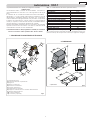 3
3
-
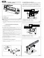 4
4
-
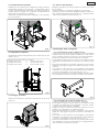 5
5
-
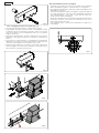 6
6
-
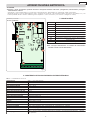 7
7
-
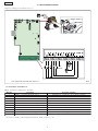 8
8
-
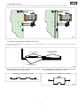 9
9
-
 10
10
-
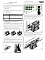 11
11
-
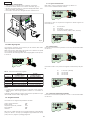 12
12
-
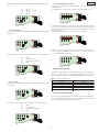 13
13
-
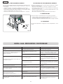 14
14
-
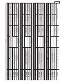 15
15
-
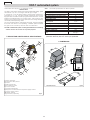 16
16
-
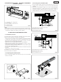 17
17
-
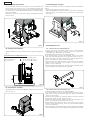 18
18
-
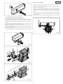 19
19
-
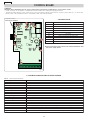 20
20
-
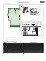 21
21
-
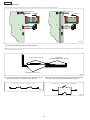 22
22
-
 23
23
-
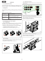 24
24
-
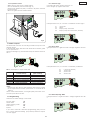 25
25
-
 26
26
-
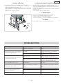 27
27
-
 28
28
-
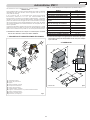 29
29
-
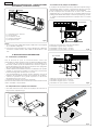 30
30
-
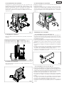 31
31
-
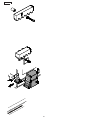 32
32
-
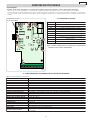 33
33
-
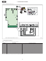 34
34
-
 35
35
-
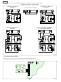 36
36
-
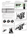 37
37
-
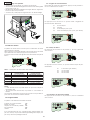 38
38
-
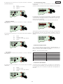 39
39
-
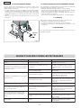 40
40
-
 41
41
-
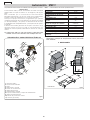 42
42
-
 43
43
-
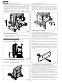 44
44
-
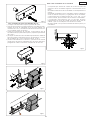 45
45
-
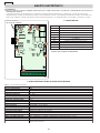 46
46
-
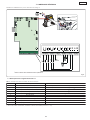 47
47
-
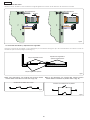 48
48
-
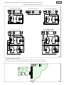 49
49
-
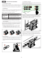 50
50
-
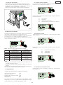 51
51
-
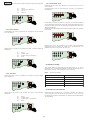 52
52
-
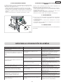 53
53
-
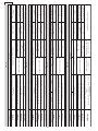 54
54
-
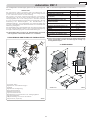 55
55
-
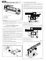 56
56
-
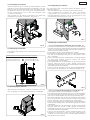 57
57
-
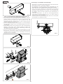 58
58
-
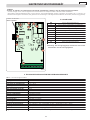 59
59
-
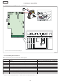 60
60
-
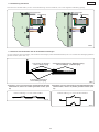 61
61
-
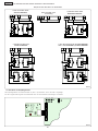 62
62
-
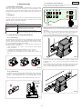 63
63
-
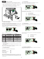 64
64
-
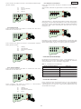 65
65
-
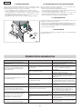 66
66
-
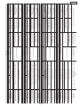 67
67
-
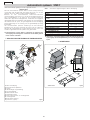 68
68
-
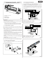 69
69
-
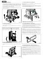 70
70
-
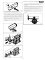 71
71
-
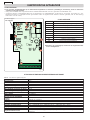 72
72
-
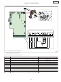 73
73
-
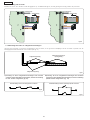 74
74
-
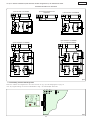 75
75
-
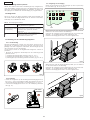 76
76
-
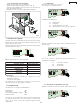 77
77
-
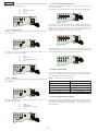 78
78
-
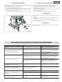 79
79
-
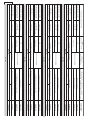 80
80
-
 81
81
-
 82
82
-
 83
83
-
 84
84
-
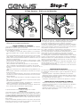 85
85
-
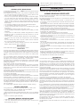 86
86
-
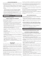 87
87
-
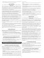 88
88


En otros idiomas
- français: Genius STEP T Mode d'emploi
- italiano: Genius STEP T Istruzioni per l'uso
- Deutsch: Genius STEP T Bedienungsanleitung
- Nederlands: Genius STEP T Handleiding
Documentos relacionados
-
Genius STEP T Instrucciones de operación
-
-
-
-
-
-
-
-
-


