

ENGLISH
ENGLISH-02
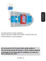
Before using your new Electronic Snap Circuits, please read this
instruction manual to prevent any damage. Put it away in a safe
place for future references.
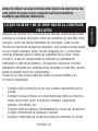
DO’s AND DON’Ts OF BUILDING CIRCUITS
After building the circuits given in this booklet, you may wish to
experiment on your own. Use the projects in this booklet as a guide, as
many important design concepts are introduced throughout them. Every
circuit will include a power source (the batteries), a resistance
(which might be a resistor, lamp, motor, integrate circuit, etc.), and
wiring paths between them and back. You must be careful not to create
“short circuits” as this will damage components and / or quickly drain
the batteries. Only connect the ICs using confi gurations given in the
projects, incorrectly doing so may damage them.
Steren is not responsible for parts damaged due to incorrect wiring.
Always use eye protection when experimenting on your own.
Always include at least one component that will limit the current
through a circuit, such as the speaker, lamp, capacitors, motor,
microphone, etc.
Always disconnect the batteries immediately and check your wiring
if something appears to be getting hot.
Always check your wiring before turning on a circuit.
Never leave a circuit unattended when it is turned on.
Never touch the motor when it is spinning at high speed.
•
•
•
•
•
•
Before usin
g
y
our new Electronic Snap Circuits, please read this
i
nstruction manual to prevent an
y
dama
g
e. Put it awa
y
in a safe
p
lace for future references
.

ENGLISH
ENGLISH-03
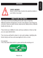
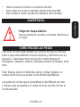
WARNING
SHOCK HAZARD
Never connect snap circuits to the electrical outlets in
your home in any way!
HOW TO USE THE PARTS
The snap circuit kit uses building blocks with snaps to build the
different electrical and electronic circuits in the projects. Each block has
a function: there are switch blocks, lamp blocks, battery blocks, different
length wire blocks, etc.
These blocks are indifferent colors and have numbers on them so that
you can easily identify them.
The circuit you will build is shown in color and numbers, identifying the
blocks that you will use and snap together to form a circuit.
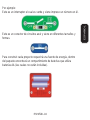
For example:
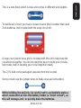
This is the switch block which is green and has the marking on it.

ENGLISH
ENGLISH-04
This is a wire block which is blue and comes in different wire lengths.
To build each circuit, you have a power source block number that need
2 AA batteries (not included with the snap circuit kit).
A large clear plastic base grid is included with this kit to help keep the
circuit block together. You do not need this base to build your circuits,
but it does help in keeping your circuit together neatly.
The 2,5V bulb come packaged separate from their socket.
Some circuits use the jumper wires to make unusual connections
While building the projects, be careful not to accidentally make a
direct connection across the battery holder (a “short circuit”), as
this will damage and / or quickly drain the batteries.
W
hile buildin
g
the pro
j
ects, be careful not to accidentall
y
make a
d
irect connection across the batter
y
holder
(
a “short circuit”
)
, as
t
his will dama
g
e and
/
or quickl
y
drain the batteries
.

ENGLISH
ENGLISH-05
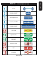
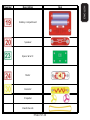
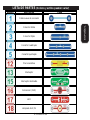
PART LIST (Colors and styles may vary)
Number Descri
p
tion Item
Soft wire
Two-snap connector
Three-snap connector
Four-snap connector
Five-snap connector
Touch plate
Dry reed switch
Slide switch
Photosensor (CdS)
LED
2,5V Lamp

ENGLISH
ENGLISH-06
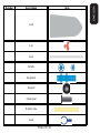
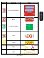
Number Descri
p
tion Item
Speaker
Resistor
Propeller
Elastic bands
Space War IC
Motor
Battery compartment

ENGLISH
ENGLISH-07
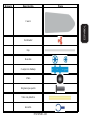
Number Descri
p
tion Item
Fan
Axle
Whells
Bodywork
Magnet
Small gear
Rubber tube
Seat
Hull

ENGLISH
ENGLISH-08
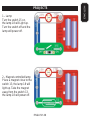
PROJECTS
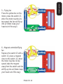
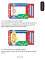
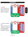
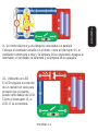
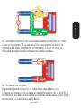
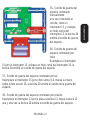
1.- Lamp
Turn the switch 15 on,
the lamp 18 will Light up.
Turn the switch off and the
lamp will power off.
2.- Magnet-controlled lamp
Place a magnet close to the
switch 13, the lamp 18 will
light up. Take the magnet
away from the switch 13,
the lamp 18 will power off.

ENGLISH
ENGLISH-09
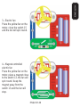
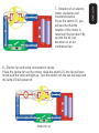
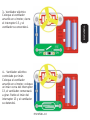
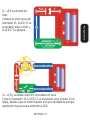
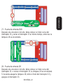
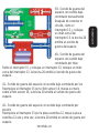
3.- Electric fan
Place the yellow fan on the
motor, close the switch 15
and the fan will spin round.
4.- Magnet-controlled
electric fan
Place the yellow fan on the
motor, place a magnet close
to the switch 13, the fan will
spin round. Keep the
magnet away from the
switch 13 and the fan will
stop.

ENGLISH
ENGLISH-10
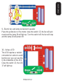
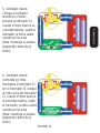
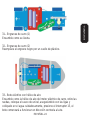
5.- Flying fan
Place the yellow fan on the
motor, press the switch 15,
when the motor reaches its
top speed, the fan will fl y up
into air (Note: keep your
head out of the way!)
6.- Magnet-controlled fl ying
fan
Replace the switch 15 with a
switch 13, place a magnet
close to the switch 13, when
the motor reaches its top
speed, take the magnet
away from the switch and fan
will fl y up into air (Note: keep
your head out of the way).

ENGLISH
ENGLISH-11
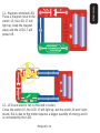
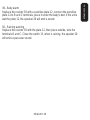
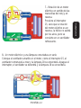
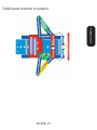
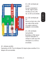
7.- Rotation of an electric
motor clockwise and
counterclockwise
Press the switch 15, you
will see the that the
rotation of the motor is
reversed, the fan won’t fl y
up into the air, but
becomes in an air
conditioner fan.
8.- Electric fan and lamp connected in series
Place the yellow fan on the motor, close the switch 15, the fan will spin
round and the lamp will light up. Turn the switch off, the fan will stop and
the lamp 18 will power off.

ENGLISH
ENGLISH-12
9.- Electric fan and lamp connected in parallel
Place the yellow fan on the motor, close the switch 15, the fan will spin
round and the lamp 18 will light up. Turn the switch off, the fan will stop
and the lamp 18 will power off.
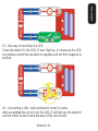
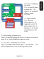
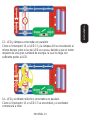
10.- Using a LED
The LED requires a resistor
connected un series to avoid
burning out, you can see this
in the underside of the LED.
Close the switch 15, the LED
17 will light up.

ENGLISH
ENGLISH-13
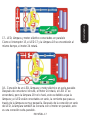
11.- Magnet-controlled LED
Place a magnet close to the
switch 13, the LED 17 will
light up, keep the magnet
away and the LED 17 will
power off.
12.- LED and electric fan connected in series
Close the switch 15, the LED 17 will light up, but the motor 24 won’t spin
round, this is due to the motor requires a bigger quantity of energy and it
is consumed by the LED.

ENGLISH
ENGLISH-14
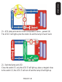
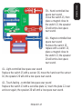
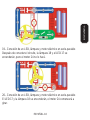
13.- LED and lamp connected in parallel
Close the switch 15, the LED 17 and the lamp 18 will light up at the
same time, but the LED light will be dark, it is because the motor
requires bigger quantity of energy than the LED.
14.- LED and electric fan connected in parallel
Close the switch 15,m the LED 17 will light up and the fan will spin
round.

ENGLISH
ENGLISH-15
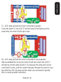
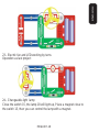
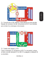
15.- One way conductivity of a LED
Close the switch 15, the LED 17 won’t light up, it is because the LED
only allows current from positive to negative and not from negative to
positive.
16.- Connecting a LED, lamp and electric motor in series
After assembled the circuit, only the LED 17 will light up, the lamp 18
and the motor 24 won’t work because of the low current.

ENGLISH
ENGLISH-16
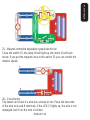
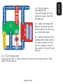
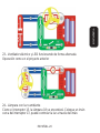
17.- LED, lamp and electric motor connected in parallel
Close the switch 15, the LED 17 and the lamp 18 will light up at the
same time, the motor 24 will spin round.
18.- LED, lamp and electric motor connected in series-parallel
After assembled the circuit, the motor 24 will spin round, the LED 17
will light up, but the lamp 18 won’t, it is because the lamp and Led are
connected in series, and the current that pass through the lamp it is very
low. After the LED, the lamp and the motor are connected in parallel,
this is a series-parallel connection.

ENGLISH
ENGLISH-17
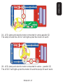
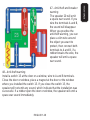
19.- LED, lamp and electric motor connected in series-parallel (2)
The lamp 18 and the LED 17 will light up but the motor 24 won’t.
20.- LED, lamp and electric motor connected in series – parallel (3)
The LED 17 will light up but the motor 24 and the lamp 18 won’t work.

ENGLISH
ENGLISH-18
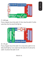
21.- LED, lamp and electric motor connected in series – parallel (4)
The LED 17 will light up but the motor 24 and the lamp 18 won’t work
22.- Switched lamp and LED
Close the switch 15, only the LED 17 will light up, place a magnet close
to the switch 13, the LED 17 will turn off and the lamp 18 will light up.

ENGLISH
ENGLISH-19
23.- Electric fan and LED working by turns
Operation as last project
24.- Changeable-light lamp
Close the switch 15, the lamp 18 will light up, Place a magnet close to
the switch 13, then you can control the lamp with a magnet.

ENGLISH
ENGLISH-20
25.- Magnet-controlled adjustable speed electric fan
Close the switch 15, the lamp 18 will light up, the motor 24 will spin
round, if you put the magnet close to the switch 13 you can control the
rotation speed.
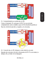
26.- Circuit tester
The tester can check if a wire has a break or not. Place the two ends
of the wire on A and B terminals, if the LED 17 lights up, the wire is not
damaged, but if not, the wire is broken.

ENGLISH
ENGLISH-21
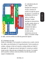
27.- AND gate
Place a magnet close to the switch 13, then close the switch 15 at the
same time, then the lamp 18 will light up.
28.- OR gate
Place a magnet close to the switch 13 or close to the switch 15, the
lamp 18 will light up. If you need to turn the lamp 18 off, remove the
switch 13 and turn the switch 15 off.

ENGLISH
ENGLISH-22
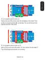
29.- Air propeller electric motor car
Remove the nut of the motor, place the red blade on the motor. Then
put the car at ground level after connecting. The car will move on the
opposite direction of the wind.
30.- Air propeller electric motor car (2)
Add a LED to each end of the switch 15, then connect it to the plate 3.
The LED will light up whilst the car is running.

ENGLISH
ENGLISH-23
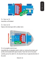
31.- Gear car (1)
Assemble as illustrated
32.- Gear car (2)
Replace the black gear with a rubber neck.
33.- Air propeller electric boat
Assemble the air propeller electric motor car, remove the wheels and
put the hull fastened with elastic bands. Place the hull on the water
carefully, press the switch 15, the boat will move in opposite direction of
the wind.

ENGLISH
ENGLISH-24
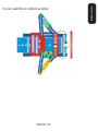
You can assemble an airplane as below:

ENGLISH
ENGLISH-25
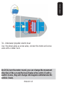
34.- Underwater propeller electric boat
Use the wheel axles as screw axles, connect the motor and screw
axles with a rubber neck.
(In 29-34, turn the motor round, you can change the movement
direction of the car and the boat. Replace the switch 15 with a
switch 13 also, they will change into magnet-controlled electric
vehicle / boat).
(
In 29-34, turn the motor round,
y
ou can chan
g
e the movement
d
irection of the car and the boat. Re
p
lace the switch 15 with a
s
witch 13 also, the
y
will chan
g
e into ma
g
net-controlled electric
v
ehicle / boat
).

ENGLISH
ENGLISH-26
35.- Hand-controlled space
war sound
Close the switch 15, place
a magnet close to the
switch 13, the speaker 20
will emit a space
war sound.
36.- Magnet-controlled
space war sound
Remove the switch 15,
replace with a switch 13,
place a magnet close to
the switch 13, the speaker
20 will emit a space war
sound.
37.- Light-controlled space war sound
Replace the switch 15 with a photo sensor 16, move your hand over the
sensor 16, the speaker 20 will emit a space war sound.
38.- Touch-feeling-controlled space war sound
Replace the switch 13 with a sensitive plate 12, touch the plate 12 over
and over again, the speaker 20 will emit a space war sound.

ENGLISH
ENGLISH-27
39.- Hand controlled low
space war sound
Close the switch 15, then
place a magnet close to
the switch 13, the speaker
20 will emit a low space
war sound.
40.- Magnet-controlled low
space war sound
Remove the switch 15,
replace with a switch 13,
place a magnet close to
the switch 13, the speaker
20 will emit a low space
war sound.
41.- Light-controlled low space war sound
Replace the switch 15 with a sensor 16, move the hand over the sensor
16, the speaker 20 will emit a low space war sound.
42.- Touch-feeling –controlled low space war sound
Replace the switch 13 with a sensitive plate 12, touch the plate 12 over
and over again, the speaker 20 will emit a low space war sound.

ENGLISH
ENGLISH-28
43.- Touch-feeling-
controlled LED
Touch the plate 12 over
and over again, the LED
will light up.
44.- Light-controlled LED
Move your hand over the
photo sensor 16, then you
can control the light.
45.- Hand-controlled LED
Replace the photo sensor
16 with a switch 13, then
place a magnet close to
the switch 13, the LED will
light up.
46.- Touch-feeling lamp
Replace the LED 17 with a lamp 18, touch the sensitive plate 12, the
lamp 18 will light up.

ENGLISH
ENGLISH-29
47.- Anti-theft and breaker
warning
The speaker 20 will emit
a space war sound. If you
wire the terminals A and B,
the sound will disappear.
When you practice the
anti-theft warning, you can
place a slim wire around
the object you want to
protect, then connect both
terminals to A and B, if a
robber breaks the wire, the
speaker will emit a space
war sound.
48.- Anti-theft warning
Install a switch 13 at the door or a window, wire to A and B terminals.
Close the door or window, place a magnet at the door or the window
where you installed the switch 13. If you close the switch 15, the
speaker will not emit any sound, which indicate that the installation was
successful. If a robber open the door or window, the speaker will emit a
space war sound immediately.

ENGLISH
ENGLISH-30
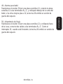
49.- Baby alarm
Replace the resistor 30 with a sensitive plate 12, connect the sensitive
plate 12 to B and C terminals, place it under the baby’s bed, if the urine
wet the plate 12, the speaker 20 will emit a sound.
50.- Raining warning
Replace the resistor 30 with the plate 12, then place outside, wire the
terminals B and C. Close the switch 15, when is raining, the speaker 20
will emit a space war sound.

ENGLISH
ENGLISH-31
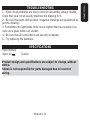
TROUBLESHOOTING
1.- Most circuit problems are due to incorrect assembly, always double
check that your circuit exactly matches the drawing for it.
2.- Be sure that parts with positive / negative markings are positioned as
per the drawing.
3. Sometimes the light bulbs come loose, tighten them as needed. Use
care since glass bulbs can shatter.
4.- Be sure that all connections are securely snapped.
5.- Try replacing the batteries.
SPECIFICATIONS
Input module
Input: 3V (2xAA)
Product design and specifi cations are subject to change, without
notice.
Steren is not responsible for parts damaged due to incorrect
wiring.
P
roduct desi
g
n and specifi cations are sub
j
ect to chan
g
e, without
n
otice
.
S
teren is not responsible for parts dama
g
ed due to incorrect
w
irin
g.

ENGLISH
ENGLISH-32
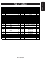
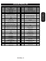
PROJECT LISTINGS
Pro
j
ect Descri
p
tion Pa
g
. # Pro
j
ect Descri
p
tion Pa
g
. #
1
Lamp
826
Circuit tester
20
2
Magnet-controlled lamp
827
AND gate
21
3
Electric fan
928
OR gate
21
4
Magnet-controlled electric fan
929
Air propeller electric motor car
22
5
Flying fan
10 30
Air propeller electric motor car (2)
22
6
Magnet-controlled flying fan
10 31
Gear car (1)
23
7
Rotation of an electric motor clockwise and
counterclockwise
11 32
Gear car (2)
23
8
Electric fan and lamp connected in series
11 33
Air propeller electric boat
23
9
Electric fan and lamp connected in parallel
12 34
Underwater propeller electric boat
25
10
Using a LED
12 35
Hand-controlled space war sound
26
11
Magnet-controlled LED
13 36
Magnet-controlled space war sound
26
12
LED and electric fan connected in series
13 37
Light-controlled space war sound
26
13
LED and lamp connected in parallel
14 38
Touch-feeling-controlled space war sound
26
14
LED and electric fan connected in parallel
14 39
Hand controlled low space war sound
27
15
One way conductivity of a LED
15 40
Magnet-controlled low space war sound
27
16
Connecting a LED, lamp and electric motor in
series
15 41
Light-controlled low space war sound
27
17
LED, lamp and electric motor connected in
p
arallel
16 42
Touch-feeling –controlled low space war sound
27
18
LED, lamp and electric motor connected in series-
p
arallel
16 43
Touch-feeling-controlled LED
28
19
LED, lamp and electric motor connected in series-
p
arallel
(
2
)
17 44
Light-controlled LED
28
20
LED, lamp and electric motor connected in series
–
p
arallel
(
3
)
17 45
Hand-controlled LED
28
21
LED, lamp and electric motor connected in series
–
p
arallel
(
4
)
18 46
Touch-feeling lamp
28
22
Switched lamp and LED
18 47
Anti-theft and breaker warning
29
23
Electric fan and LED working by turns
19 48
Anti-theft warning
29
24
Changeable-light lamp
19 49
Baby alarm
30
25
Magnet-controlled adjustable speed electric fan
20 50
Raining warning
30

WARRANTY
This Steren product is warranted under normal usage against defects in workmanship and
materials to the original purchaser for one year from the date of purchase.
CONDITIONS
1.- This warranty card with all the required information, invoice or purchase ticket, product
box or package, and product, must be presented when warranty service is required.
2.- If the product stills on the warranty time, the company will repair it free of charge.
3.- The repairing time will not exceed 30 natural days, from the day the claim was received.
4.- Steren sell parts, components, consumables and accessories to customer, as well as
warranty service, at any of the addresses mentioned later.
THIS WARRANTY IS VOID IN THE NEXT CASES:
If the product has been damaged by an accident, acts of God, mishandling, leaky batteries,
failure to follow enclosed instructions, improper repair by unauthorized personnel, improper
safe keeping, among others.
a) The consumer can also claim the warranty service in the purchase establishment.
b) If you lose the warranty card, we can reissue it, if you show the invoice or purchase ticket.
Product: Electronic Snap Circuits
Part number: K-800
Brand: Steren

RETAILER INFORMATION
Name of the retailer
Address
Product
Brand
Part number
Serial number
Date of delivery
In case your product fails or have questions, please contact your nearest dealer. If
you are in Mexico, please give a call to our Call Center.
Call Center
01 800 500 9000


Antes de utilizar su nuevo Kit educativo básico de electrónica lea
este instructivo para evitar cualquier mal funcionamiento.
Guárdelo para futuras referencias.
LO QUE SE DEBE Y NO SE DEBE HACER AL CONSTRUIR
CIRCUITOS
Después de construir los circuitos de este manual, usted podría desear
construir sus propios proyectos. Utilice los proyectos en este libro como
una guía, como una fuente importante de conceptos. Cada circuito
incluirá una fuente de energía (las baterías), una resistencia (que puede
ser un resistor, lámpara, motor, circuito integrado, etc.) y conectores
entre las diferentes piezas. Debe ser cuidadoso de no crear “cortos
circuitos” ya que los componentes se dañarán y/o rápidamente
extinguirán la vida de las baterías. Únicamente conecte los circuitos
integrados utilizando las confi guraciones ofrecidas en este libro, de otra
forma se pueden dañar los componentes.
Steren no se hace responsable por daños en piezas debido a un
incorrecto ensamblaje.
Siempre utilice protección en los ojos cuando experimente por su
cuenta.
Siempre incluya al menos un componente que limite la corriente a
través del circuito, como una bocina, lámpara, capacitores,
motores, micrófonos, etc.
Siempre retire las baterías inmediatamente y revise las conexiones
si algún componente se empieza a calentar.
Siempre compruebe las conexiones antes de encender el circuito.
•
•
•
•
ESPAÑOL-02
ESPAÑOL
A
ntes de utilizar su nuevo Kit educativo básico de electrónica lea
e
ste instructivo para evitar cualquier mal funcionamiento.
G
uárdelo para futuras referencias
.

Nunca conecte el circuito a un contacto eléctrico
Nunca deje un circuito sin atender cuando esté encendido
Nunca toque el motor cuando esté rotando a alta velocidad
ADVERTENCIA
Peligro de choque eléctrico
Nunca conecte los circuitos a contactos eléctricos en
su hogar
COMO UTILIZAR LAS PIEZAS
Este kit de circuitos utiliza bloques de construcción que se conectan
entre sí para armar diferente circuitos eléctricos y electrónicos en los
proyectos. Cada bloque tiene una función: existen bloques de
interruptores, lámparas, baterías, diferentes tamaños de bloques, entre
otros.
Estos bloques vienen en diferentes colores y tienen impresos un
número de tal forma que puedan ser fácilmente identifi cables.
Las partes del circuito que se ensamblará se identifi carán por color
y número, para que puedan ser unidas de forma sencilla y formar el
circuito deseado.
•
•
•
ESPAÑOL-03
ESPAÑOL

Por ejemplo:
Este es un interruptor el cual es verde y viene impreso un número en él.
Este es un conector de circuitos azul y viene en diferentes tamaños y
formas.
Para construir cada proyecto requerirá una fuente de energía, dentro
del paquete encontrará un compartimiento de baterías que utiliza
baterías AA (las cuales no están incluidas).
ESPAÑOL-04
ESPAÑOL

También se incluye una placa plástica para ayudar a mantener los
bloques de circuitos unidos. No es necesario utilizar esta placa para
construir proyectos, sin embargo ayuda a que los bloques se
mantengan juntos.
La bombilla de 2,5V viene separado del socket.
Algunos circuitos utilizan cables de puenteo para realizar conexiones no
usuales.
Mientras construye los proyectos, asegúrese de que los cables no
toquen el compartimiento de baterías, de forma accidental, de otra
forma podría provocar un corto circuito y dañará las baterías.
ESPAÑOL-05
ESPAÑOL
M
ientras constru
y
e los pro
y
ectos, ase
g
úrese de que los cables no
t
oquen el compartimiento de baterías, de forma accidental, de otra
f
orma podría provocar un corto circuito
y
dañará las baterías
.

LISTA DE PARTES (Colores y estilos pueden variar)
ESPAÑOL-06
ESPAÑOL
Número Descri
p
ción Pieza
Cable suave de conexión
Conector doble
Conector triple
Conector cuádruple
Conector quíntuple
Placa sensitiva
Interruptor
Interruptor deslizable
Fotosensor (CdS)
LED
Lámpara de 2,5V

ESPAÑOL-07
ESPAÑOL
Número Descri
p
ción Pieza
Bocina
Resistor
Hélices
Ligas
Compartimiento de batería
CI guerra del espacio
Motor

ESPAÑOL-08
ESPAÑOL
Número Descri
p
ción Pieza
Ventilador
Eje
Ruedas
Cuerpo de trabajo
Imán
Engrane pequeño
Tubo de plástico
Asiento
Casco

EXPERIMENTOS
1.- Lámpara
Cierre el interruptor 15 y la
lámpara 18 se encenderá.
Apague el interruptor y la
lámpara 18 se apagará.
2.- Lámpara controlada por
imán
Coloque un imán cerca del
interruptor 13, la lámpara 18
se encenderá. Retire el
imán del interruptor 13,
la lámpara 18 se apagará.
ESPAÑOL-09
ESPAÑOL

3.- Ventilador eléctrico
Coloque el ventilador
amarillo en el motor, cierre
el interruptor 15, y el
ventilador se encenderá.
4.- Ventilador eléctrico
controlado por imán
Coloque el ventilador
amarillo en el motor, coloque
un imán cerca del interruptor
13, el ventilador comenzará
a girar. Retire el imán del
interruptor 13 y el ventilador
se detendrá.
ESPAÑOL-10
ESPAÑOL

5.- Ventilador volante
Coloque el ventilador
amarillo en el motor,
presione el interruptor 15,
cuando el motor alcance su
velocidad máxima, suelte el
interruptor, la hélice saldrá
volando por los aires
(Nota: mantenga su cabeza
alejada del camino de la
hélice).
6.- Ventilador volante
controlado por imán
Reemplace el interruptor 15
por el interruptor 13, coloque
un imán cerca del interruptor
13, cuando el motor alcance
la velocidad máxima, suelte
el interruptor, la hélice saldrá
volando por los aires
(Nota: mantenga su cabeza
alejada del camino de la
hélice).
ESPAÑOL-11
ESPAÑOL

7.- Rotación de un motor
eléctrico en sentido de las
manecillas del reloj y en
reversa
Presione el interruptor
15, verá que la rotación
del motor eléctrico es en
reversa, la hélice no saldrá
por los aires, pero se
convierte en un ventilador
refrescante.
8.- Un motor eléctrico y una lámpara conectadas en serie
Coloque el ventilador amarillo en el motor, cierre el interruptor 15, el
ventilador comenzará a rotar y la lámpara 18 se encenderá. Apague el
interruptor, el ventilador se detendrá y la lámpara 18 se encenderá.
ESPAÑOL-12
ESPAÑOL

9.- Un motor eléctrico y una lámpara conectadas en paralelo
Coloque el ventilador amarillo en el motor, cierre el interruptor 15, el
ventilador comenzará a rotar y la lámpara 18 se encenderá, Apague el
interruptor, el ventilador se detendrá y la lámpara 18 se apagará.
10.- Utilizando un LED
El LED requiere la conexión
de un resistor en serie para
prevenir que se queme,
puede verlo debajo del LED.
Cierre el interruptor 15, el
LED 17 se encenderá.
ESPAÑOL-13
ESPAÑOL

11.- LED controlado por
imán
Coloque un imán cerca del
interruptor 13, el LED 17 se
encenderá, aleje el imán y
el LED 17 se apagará.
12.- LED y ventilador eléctrico conectados en serie
Cierre el interruptor 15, el LED 17 se encenderá, pero el motor 24 no
rotará, debido a que el motor requiere una gran cantidad de energía,
quedando muy poca para alimentar al LED.
ESPAÑOL-14
ESPAÑOL

13.- LED y lámpara conectadas en paralelo
Cierre el interruptor 15, el LED 17 y la lámpara 18 se encenderán al
mismo tiempo, pero la luz del LED es oscura, debido a que el motor
requiere de una gran cantidad de energía, la cual no llega con
sufi ciente poder al LED.
14.- LED y ventilador eléctrico conectados en paralelo
Cierre el interruptor 15, el LED 17 se encenderá y el ventilador
comenzará a rotar.
ESPAÑOL-15
ESPAÑOL

15.- Conductividad de un sentido de un LED
Cierre el interruptor 15, verá que el LED 17 no se enciende
completamente, esto es debido a que el LED únicamente permite el
fl ujo de corriente de positivo a negativo y no viceversa.
16.- Conexión de un LED, lámpara y motor eléctrico en serie
Después de conectar el circuito, únicamente el LED 17 se enciende, la
lámpara 18 y el motor 24 no trabajarán.
ESPAÑOL-16
ESPAÑOL

17.- LED, lámpara y motor eléctrico conectados en paralelo
Cierre el interruptor 15, el LED 17 y la lámpara 18 se encenderán al
mismo tiempo, el motor 24 rotará.
18.- Conexión de un LED, lámpara y motor eléctrico en serie-paralelo
Después de conectar el circuito, el motor 24 rotará, el LED 17 se
encenderá, pero la lámpara 18 no lo hará, esto es debido a que la
lámpara y el LED están conectados en serie, la corriente que pasa a
través de la lámpara es muy pequeña. Después de la conexión en serie
del LED, la lámpara también se conecta con el motor en paralelo, esto
es una conexión serie-paralelo.
ESPAÑOL-17
ESPAÑOL

19.- Conexión de un LED, lámpara y motor eléctrico en serie-paralelo
Después de conectar el circuito, la lámpara 18 y el LED 17 se
encenderán, pero el motor 24 no lo hará.
20.- Conexión de un LED, lámpara y motor eléctrico en serie-paralelo
El LED 17 y la lámpara 18 se encenderán, el motor 24 comenzará a
girar.
ESPAÑOL-18
ESPAÑOL

21.- Conexión de un LED, lámpara y motor eléctrico en serie-paralelo
Después de conectar el circuito, únicamente el LED 17 se encenderá,
pero el motor 24 y la lámpara no funcionarán.
22.- Cambio entre lámpara y LED
Cierre el interruptor 15, únicamente el LED 17 se encenderá, coloque
un imán cerca del interruptor 13, el LED 17 se apagará y la lámpara 18
se encenderá.
ESPAÑOL-19
ESPAÑOL

23.- Ventilador eléctrico y LED funcionando de forma alternada
Operación como en el proyecto anterior
24.- Lámpara con luz cambiante
Cierre el interruptor 15, la lámpara 18 se encenderá. Coloque un imán
cerca del interruptor 13, puede controlar la luz a través del imán.
ESPAÑOL-20
ESPAÑOL

25.- Ventilador eléctrico con velocidad variable controlado por imán
Cierre el interruptor 15, la lámpara 18 se encenderá, el motor 24
comenzará a rotar, controlando el interruptor 13 con un imán, la
velocidad de rotación del ventilador se podrá cambiar.
26.- Probador de circuitos
El probador puede revisar si un cable tiene algún daño o no.
Coloque las puntas de los cables en las terminales A y B, si el LED 17
se enciende el cable se encuentra en buenas condiciones, si el LED 17
no enciende, el cable tiene algún daño.
ESPAÑOL-21
ESPAÑOL

27.- Puerta de entrada AND
Después de conectar el circuito, debe colocar un imán cerca del
interruptor 13 y cerrar el interruptor 15 al mismo tiempo, entonces la
lámpara 18 se encenderá.
28.- Puerta de entrada OR
Después de conectar el circuito, debe colocar un imán cerca del
interruptor 13, o cerrar el interruptor 15, la lámpara 18 se encenderá.
Si necesita apagar la lámpara 18, retire el imán del interruptor 13 y
apague el interruptor 15.
ESPAÑOL-22
ESPAÑOL

29.- Motor de carro eléctrico con hélice de aire
Retire la tuerca del motor, coloque la hélice roja sobre el motor.
Coloque el carro al nivel del piso después de conectarlo, el carro se
moverá en sentido contrario a la dirección del viento.
(Ponga atención a la posición de las ruedas).
30.- Motor de carro eléctrico con hélice de aire (2)
Agregue un LED 17 a una de las terminales del interruptor 15 y conecte
con un cable 3. El LED se encenderá mientras el carro está en
movimiento.
ESPAÑOL-23
ESPAÑOL

31.- Engranes de carro (1)
Ensamble como se ilustra.
32.- Engranes de carro (2)
Reemplace el engrane negro por un cuello de plástico.
33.- Bote eléctrico con hélice de aire
Ensamble como la hélice de aire del motor eléctrico de carro, retire las
ruedas, coloque el casco de unicel, asegurándolo con las ligas y
colóquelo en el agua cuidadosamente, presione el interruptor 15, el
bote comenzará a funcionar en dirección contraria al aire.
ESPAÑOL-24
ESPAÑOL

También puede ensamblar un aeroplano:
ESPAÑOL-25
ESPAÑOL

34.- Bote eléctrico con hélice submarina
Utilice los ejes de las ruedas como tornillos, conecte el motor y los
tornillos mediante un cuello de plástico.
(En los proyectos 29 al 34, gire el motor, puede cambiar la
dirección de movimiento del vehículo y el bote. También reemplace
el interruptor 15 por el interruptor 13, cambiarán a un vehículo o
bote controlados por imán).
ESPAÑOL-26
ESPAÑOL
(
En los pro
y
ectos 29 al 34,
g
ire el motor, puede cambiar la
d
irección de movimiento del vehículo
y
el bote. También reemplac
e
e
l interru
p
tor 15
p
or el interru
p
tor 13, cambiarán a un vehículo o
b
ote controlados por imán
).

35.- Sonido de guerra del
espacio controlado
manualmente
Una vez conectado el
circuito, cierre el
interruptor 15, y coloque
un imán cerca del
interruptor 13, la bocina 20
emitirá el sonido de guerra
del espacio.
36.- Sonido de guerra del
espacio controlado por
imán
Reemplace el interruptor
15 por un interruptor 13, coloque un imán cerca del interruptor 13, la
bocina 20 emitirá un sonido de guerra del espacio.
37.- Sonido de guerra del espacio controlado por luz
Reemplace el interruptor 15 por el foto sensor 16, mueva su mano
sobre el foto sensor 16, la bocina 20 emitirá el sonido de la guerra del
espacio.
38.- Sonido de guerra del espacio controlado por presión
Reemplace el interruptor 13 por la placa sensitiva 12, toque la placa 12
una y otra vez, la bocina 20 emitirá el sonido de guerra del espacio.
ESPAÑOL-27
ESPAÑOL

39.- Sonido de guerra del
espacio con sonido bajo
controlado manualmente
Después de conectar el
circuito, cierre el
interruptor 15, y coloque
un imán cerca del
interruptor 13, la bocina 20
emitirá un sonido de
guerra del espacio.
40.- Sonido de guerra del
espacio con sonido bajo
controlado por imán
Retire el interruptor 15, y coloque un interruptor 13, coloque un imán
cerca del interruptor 13, la bocina 20 emitirá el sonido de guerra del
espacio.
41.- Sonido de guerra del espacio con sonido bajo controlado por luz
Reemplace el interruptor 15 por el foto sensor 16, mueva su mano
sobre el foto sensor 16, la bocina 20 emitirá el sonido de guerra del
espacio.
42.- Sonido de guerra del espacio con sonido bajo controlado por
presión
Reemplace el interruptor 13 por la placa sensitiva 12, toque la placa
sensitiva 12 una y otra vez, la bocina 20 emitirá el sonido de guerra del
espacio.
ESPAÑOL-28
ESPAÑOL

43.- LED controlado por
presión
Una vez conectado el
circuito, toque la placa
sensitiva 12 una y otra
vez, el LED se encenderá.
44.- LED controlado por
luz
Mueva su mano una y otra
vez sobre el foto sensor
16, puede controlar el
apagado o el encendido.
45.- LED controlado
manualmente
Reemplace el foto sensor
16 por el interruptor 13,
coloque un imán cerca del
interruptor 13, el LED se
encenderá.
46.- Lámpara sensible
Reemplace el LED 17 por la lámpara 18, toque la placa sensitiva 12, la
lámpara 18 se encenderá.
ESPAÑOL-29
ESPAÑOL

47.- Advertencia de anti-
robo y ruptura
Después de conectar el
circuito, la bocina 20
emitirá el sonido de guerra
del espacio. Si conecta las
terminales A y B con un
cable, el sonido se
detendrá. Cuando
practique la simulación de
un robo, puede colocar un
cable largo y delgado
alrededor del objeto a
proteger, entonces
conecte las dos
terminales A y B con el
cable, si un ladrón rompe
el cable, la bocina emitirá el sonido de guerra del espacio.
48.- Advertencia de robo
Instale un interruptor 13 en la puerta o la ventana de su cuarto, conecte
dos cables a las terminales A y B respectivamente. Cierre la puerta y/o
ventana, coloque un imán en la puerta y ventana donde se instaló el
interruptor 13. Si además cierra el interruptor 15, la bocina no emitirá
ningún sonido, indicando que la instalación fue correcta. SI un ladrón
abre la puerta o ventana, la bocina emitirá el sonido de guerra del
espacio inmediatamente.
ESPAÑOL-30
ESPAÑOL

49.- Alarma para bebé
Reemplace el resistor 30 por una placa sensitiva 12, conecte la placa
sensitiva 12 a las terminales B y C, y colóquelo debajo de la cama del
bebé, si la orina moja la placa 12, la bocina 20 emitirá un sonido de
guerra del espacio.
50.- Advertencia de lluvia
Reemplace el resistor 30 por una placa sensitiva 12 y colóquela fuera
de la casa, conecte dos cables a las terminales B y C. Cierre el
interruptor 15, cuando esté lloviendo, la bocina 20 emitirá un sonido de
guerra del espacio.
ESPAÑOL-31
ESPAÑOL

SOLUCIÓN DE PROBLEMAS
1.- La mayoría de los problemas de los circuitos es debido a un
ensamble incorrecto, siempre revise dos veces que el circuito está
correctamente armado.
2.- Asegúrese de que las partes con marcas positivas / negativas están
posicionadas como deben.
3.- Algunas veces las lámparas se afl ojan, vuelva a enroscarlas. Tenga
cuidado, ya que el vidrio de la lámpara puede romperse.
4.- Asegúrese de que todas las conexiones están correctamente
conectadas entre ellas.
5.- Intente reemplazar las baterías
ESPECIFICACIONES
Módulo de energía
Entrada: 3V (2xAA)
El diseño del producto y las especifi caciones pueden cambiar sin
previo aviso.
Steren no es responsable por daños en las piezas debido a
conexiones incorrectas.
ESPAÑOL-32
ESPAÑOL
E
l diseño del producto
y
las especifi caciones pueden cambiar sin
p
revio aviso
.
Steren no es res
p
onsable
p
or daños en las
p
iezas debido a
c
onexiones incorrectas
.

LISTA DE PROYECTOS
ESPAÑOL-33
ESPAÑOL
Pro
y
ecto Descri
p
ción Pa
g
. # Pro
y
ecto Descri
p
ción Pa
g
. #
1
Lámpara
926
Probador de circuitos
21
2
Lámpara controlada por imán
927
Puerta de entrada AND
22
3
Ventilador eléctrico
10 28
Puerta de entrada OR
22
4
Ventilador eléctrico controlado por imán
10 29
Motor de carro eléctrico con hélice de aire
23
5
Ventilador volante
11 30
Motor de carro eléctrico con hélice de aire (2)
23
6
Ventilador volante controlado por imán
11 31
Engranes de carro (1)
24
7
Rotación de un motor eléctrico en sentido de las
manecillas del relo
j
y
en reversa
12 32
Engranes de carro (2)
24
8
Un motor eléctrico y una lámpara conectadas en
serie
12 33
Bote eléctrico con hélice de aire
24
9
Un motor eléctrico y una lámpara conectadas en
p
aralelo
13 34
Bote eléctrico con hélice submarina
26
10
Utilizando un LED
13 35
Sonido de guerra del espacio controlado
manualmente
27
11
LED controlado por imán
14 36
Sonido de guerra del espacio controlado por imán
27
12
LED y ventilador eléctrico conectados en serie
14 37
Sonido de guerra del espacio controlado por luz
27
13
LED y lámpara conectadas en paralelo
15 38
Sonido de guerra del espacio controlado por
p
resión
27
14
LED y ventilador eléctrico conectados en paralelo
15 39
Sonido de guerra del espacio con sonido bajo
controlado manualmente
28
15
Conductividad de un sentido de un LED
16 40
Sonido de guerra del espacio con sonido bajo
controlado
p
or imán
28
16
Conexión de un LED, lámpara y motor eléctrico
en serie
16 41
Sonido de guerra del espacio con sonido bajo
controlado
p
or luz
28
17
LED, lámpara y motor eléctrico conectados en
p
aralelo
17 42
Sonido de guerra del espacio con sonido bajo
controlado
p
or
p
resión
28
18
Conexión de un LED, lámpara y motor eléctrico
en serie-
p
aralelo
17 43
LED controlado por presión
29
19
Conexión de un LED, lámpara y motor eléctrico
en serie-
p
aralelo
(
2
)
18 44
LED controlado por luz
29
20
Conexión de un LED, lámpara y motor eléctrico
en serie-
p
aralelo
(
3
)
18 45
LED controlado manualmente
29
21
Conexión de un LED, lámpara y motor eléctrico
en serie-
p
aralelo
(
4
)
19 46
Lámpara sensible
29
22
Cambio entre lámpara y LED
19 47
Advertencia de anti-robo y ruptura
30
23
Ventilador eléctrico y LED funcionando de forma
alternada
20 48
Advertencia de robo
30
24
Lámpara con luz cambiante
20 49
Alarma para bebé
31
25
Ventilador eléctrico con velocidad variable
controlado
p
or imán
21 50
Advertencia de lluvia
31

PÓLIZA DE GARANTÍA
Esta póliza garantiza el producto por el término de un año en todas sus partes y mano
de obra, contra cualquier defecto de fabricación y funcionamiento, a partir de la fecha de
entrega.
CONDICIONES
1.- Para hacer efectiva la garantía, presente ésta póliza y el producto, en donde fue
adquirido o en Electrónica Steren S.A. de C.V.
2.- Electrónica Steren S.A de C.V. se compromete a reparar el producto en caso de estar
defectuoso sin ningún cargo al consumidor. Los gastos de transportación serán cubiertos
por el proveedor.
3.- El tiempo de reparación en ningún caso será mayor a 30 días, contados a partir de la
recepción del producto en cualquiera de los sitios donde pueda hacerse efectiva la
garantía.
4.- El lugar donde puede adquirir partes, componentes, consumibles y accesorios, así como
hacer válida esta garantía es en cualquiera de las direcciones mencionadas
posteriormente.
ESTA PÓLIZA NO SE HARA EFECTIVA EN LOS SIGUIENTES CASOS:
1.- Cuando el producto ha sido utilizado en condiciones distintas a las normales.
2.- Cuando el producto no ha sido operado de acuerdo con el instructivo de uso.
3.- Cuando el producto ha sido alterado o reparado por personal no autorizado por
Electrónica Steren S.A. de C.V.
El consumidor podrá solicitar que se haga efectiva la garantía ante la propia casa
comercial donde adquirió el producto. Si la presente garantía se extraviara, el consumidor
puede recurrir a su proveedor para que le expida otra póliza de garantía, previa
presentación de la nota de compra o factura respectiva.
Producto: Kit educativo básico de electrónica
Modelo: K-800
Marca: Steren

DATOS DEL DISTRIBUIDOR
Nombre del Distirbuidor
Domicilio
Producto
Marca
Modelo
Número de serie
Fecha de entrega
ELECTRONICA STEREN S.A. DE C.V.
Camarones 112, Obrero Popular, 02840, México, D.F. RFC: EST850628-K51
STEREN PRODUCTO EMPACADO S.A. DE C.V.
Biólogo MaximIno Martínez No. 3408 Int. 3 y 4, San Salvador Xochimanca, México, D.F. 02870,
RFC: SPE941215H43
ELECTRONICA STEREN DEL CENTRO, S.A. DE C.V.
Rep. del Salvador 20 A y B, Centro, 06000, México. D.F. RFC: ESC9610259N4
ELECTRONICA STEREN DE GUADALAJARA, S.A.
López Cotilla No. 51, Centro, 44100, Guadalajara, Jal. RFC: ESG810511HT6
ELECTRONICA STEREN DE MONTERREY, S.A.
Colón 130 Pte., Centro, 64000, Monterrey, N.L. RFC: ESM830202MF8
ELECTRONICA STEREN DE TIJUANA, S.A. de C.V.
Calle 2a, Juárez 7636, Centro, 22000, Tijuana, B.C.N. RFC: EST980909NU5
En caso de que su producto
presente alguna falla, acuda
al centro de distribución más
cercano a su domicilio y en caso
de tener alguna duda o pregunta
por favor llame a nuestro Centro
de Atención a Clientes, en
donde con gusto le atenderemos
en todo lo relacionado con su
producto Steren.
Centro de Atención a Clientes
01 800 500 9000
-
 1
1
-
 2
2
-
 3
3
-
 4
4
-
 5
5
-
 6
6
-
 7
7
-
 8
8
-
 9
9
-
 10
10
-
 11
11
-
 12
12
-
 13
13
-
 14
14
-
 15
15
-
 16
16
-
 17
17
-
 18
18
-
 19
19
-
 20
20
-
 21
21
-
 22
22
-
 23
23
-
 24
24
-
 25
25
-
 26
26
-
 27
27
-
 28
28
-
 29
29
-
 30
30
-
 31
31
-
 32
32
-
 33
33
-
 34
34
-
 35
35
-
 36
36
-
 37
37
-
 38
38
-
 39
39
-
 40
40
-
 41
41
-
 42
42
-
 43
43
-
 44
44
-
 45
45
-
 46
46
-
 47
47
-
 48
48
-
 49
49
-
 50
50
-
 51
51
-
 52
52
-
 53
53
-
 54
54
-
 55
55
-
 56
56
-
 57
57
-
 58
58
-
 59
59
-
 60
60
-
 61
61
-
 62
62
-
 63
63
-
 64
64
-
 65
65
-
 66
66
-
 67
67
-
 68
68
-
 69
69


en otros idiomas
- English: Steren K-800 Owner's manual
Artículos relacionados
Otros documentos
-
Land Rover L322 Range Rover Workshop Manual
-
Genius STEP T Instrucciones de operación
-
Zenith Lighting Conrol Manual de usuario
-
Kyosho No.40235�@HURRICANE 900 VE Manual de usuario
-
-
-
Craftsman 12 INCH DUAL BEVEL COMPOUND MITER SAW Manufacturer's Warranty (Espanol)