Frigidaire FGS379DSA Guía de instalación
- Categoría
- Microondas
- Tipo
- Guía de instalación

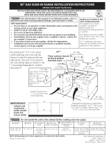
INSTALLATION AND SERVICE MUST BE PERFORMED BY A QUAUNED INSTALLER.
IMPORTANT: SAVE FOR LOCAL ELECTRICAL INSPECTOR'S USE.
READ AND SAVE THESE INSTRUCTIONS FOR FUTURE REFERENCE.
If the information in this manual is not followed exactJy, a fire or
exp!osion may resuJt causing property damage, personal injury or death.
FOR YOUR SAFETY:
-- Do not store or use gasoline or other flammable vapors and liquids in the
vicinity of this or any other appliance.
-- WHATTO DO JFYOU SMELLGAS:
• Do not try to Jight any appliance.
• Do not touch any electrical switch; do not use any phone in your building.
• tmmediateJy call your gas supplier from a neighbor's phone. Fottow the
gas supplier's instructions.
• tf you cannot reach your gas supplier, call the fire department.
-- Installation and service must be performed by a qualified installer, service
agency or the gas supplier.
Appliances installed in the
state of Massachusetts;
This Appliance can only be
installed in the state of
Massachusetts by a
Massachusett's licensed
alumber or gasfitter,
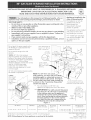
This appliance must be installed
with a three (3) foot / 36 in_
long flexible gas connector
A"T" handle type manual gas
valve must be installed in the
gas supply line to this
appliance,
\b_J
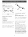
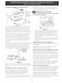
A HEIGHT, B,WIDTH C, DEPTHTO F CUTOUT G, CUTOUT DEPTH H HEIGHTOF
! ffRONT OF RANGE VVIDTH I £OUNTERTOP
35 :_/8" (90 cm) - % :_/8" (92 cm) :_0" (76,2 crn) 28 5/16" (71,9 cm) 30±1/16" 21 3/4" (55,2 cm) Min, :_6" (91,4 cm) standard
(76,2±0,I5 cm) 22 I/8" (56,2 cm) Max 35 3/8" (90 crn) rain
G Minimum Cutout Depth is increased to 24"(61 cm) with backguard. P/N 318201669 (0406) Rev A
English - pages 1-9
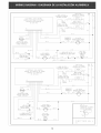
NOTE: Wiring diagram for these appliances are enclosed in this booklet. Espaflol - p_ginas 10-18
Wiring Diagrams- pages 19-20

Important Notes to the Installer
1. Read all instructions contained in these installation
instructions before installing range.
2. Remove all packing material from the oven
compartments before connecting the gas and electrical
supply to the range.
3. Observe all governing codes and ordinances.
4. Be sure to leavethese instructions with the consumer.
Important Note to the Consumer
Keep these instructions with your owner's guide for future
reference.
IMPORTANT SAFETY
IN< NS
Installation of this range must conform with local (:odes
or, in the absence of local codes, with the National Fuel
Gas Code ANS! Z223. I/NFPA .54--latest edition.
This range has been design certified by CSA
International. As with any appliance using gas and
generating heat, there are certain safety precautions you
should follow. You will find them in the Use and Care
Guide, read it carefully.
• Be sure your range is installed and grounded
properly by a qualified installer or service
technician.
• This range must be electrically grounded in
accordance with local codes or, in their absence,
with the National Electrical Code ANSI/NFPA No.
70--latest edition. SeeGrounding Instructions.
• Before installing the range in an area covered with
tinoleum or any other synthetic floor covering,
make sure the floor covering can withstand heat at
least 9O°F above room temperature without
shrinking, warping or disco!oring. Do not install the
range over carpeting unlessyou place an insulating pad
or sheet of Y4" (!0,16 cm) thick plywood between tile
range and carpeting.
All ranges
cantip.
Injuryto
persons could
result.
Install antPtip
device
packed with
range.
i_ To reduce
the risk of tipping of the
range, tile range must be
secured by properly
installed antPtip bracket
provided with the range.
To check if the bracket is
installed properly, grasp
the top rear edge of the
range and carefully tilt it
forward to make sure the
range isanchored.
Make sure the wall coverings around the range
can withstand the heat generated by the range.
Do not obstruct the flow of combustion air at the
oven vent nor around the base or beneath the
lower front panel of the range. Avoid touching tile
vent openings or nearby surfaces as they may become
hot while the oven is in operation. This range requires
fresh air for proper burner combustion.
Never leave children alone or
unattended in the area where an appliance is in use.
As children grow, teach them the proper, safe use of all
appliances. Never leave the oven door open when the
range is unattended.
Stepping, leaning or sitting on the
doors or drawers of this range can result in serious
injuries and can also cause damage to the range.
• Do not store items of interest to children in the
cabinets above the range. Children could be seriously
burned climbing on the range to reach items.
• To eliminate the need to reach over the surface
burners, cabinet storage space above the burners
should be avoided.
• Adjust surface burner flame size so it does not
extend beyond the edge of the cooking utensil.
Excessive flame is hazardous.
• Do not use the oven as a storage space. This
creates a potentially hazardous situation.
• Never use your range for warming or heating the
room. Prolonged use of the range without adequate
ventilation can be dangerous.
• Do not store or use gasoline or other flammable
vapors and liquids near this or any other
appliance. Explosions or fires could result.
In the event of an electrical power outage, the surface
burners can be lit manually. To light a surface burner,
hold a lit match to the burner head and slowly turn the
Surface Control knob to LITE.Use caution when
lighting surface burners manually.
• Reset alt controls to the "off" position after using
a programmable timing operation.
FOR MODELS WITH SELF-CLEAN FEATURE:
Remove broiler pan, food and other utensils
before self-cleaning the oven. Wipe up excess
spillage. Follow the precleaning instructions in tile Use
and Care Guide.
• Unlike the standard gas range, THIS COOKTOP tS
NOT REMOVABLE. Do not attempt to remove the
cooktop.

Cabinet Construction
To eliminate the risk of burns or fire by
reaching over heated surface units, do not have cabinet
storage space above the range. If there is cabinet
storage space above range, reduce the risk by installing
a range hood that projects horizontally a minimum of
5"(12.7 cm) beyond the bottom of the cabinet.
Countertop Preparation
The cooktop sides of the range fit over the cutout
edge of your countertop.
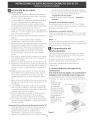
If you have asquare finish (fiat) countertop, no
countertop preparation is required.
Formed front-edged countertops must have
molded edge shaved flat 3/4"(1.9 cm) from each
front corner of opening.
• Tile countertops
may need trim cut
back 3/4"(I .9 cm)
(I .9 cm) from
each front corner
and/or rounded
edge flattened.
314"
_._ cu!out
"B/wIdth 31 1/2
(81 cm)
__ Formed or tiled countertop
_3/4" " trimmed 3/4" (1.9cm)
(1.9 cm) back at from corners of
I countertop opening.
Figure 2
• tf the countertop opening width is greater than
the minimum cutout width, adjust the 3/4" (1.9
cm) dimension.
For countertop of 29" (73.7cm} cutout
wide opening:
You must clear 2V_J'
2_/_j ' (5.6 cm} from front
of countertop to fit
the range in the
11/4`` cabinet,
(3.2 cm)
p:
trimmed 1%" (3,2 cm) back at front
corners of countertop opening for
29" cut out wide opening,
Figure 3
• Countertop must be JeveL Place a level on the
countertop, first side to side, then front to back. If the
countertop is not level, the range will not be level.
The oven must be level for satisfactory baking results.
Provide an adequate Gas Supply
When shipped from the factory, this unit is designed to
operate on 4"(10,16 cm) water column (!.0 kPa) Natural
gas manifold pressure. A convertible pressure regulator is
connected to the range manifold and MUST be
connected in series with the gas supply line. If LP/
Propane conversion kit has been used, follow instructions
provided with the kit for converting the pressure
regulator to LP/Propane use.
Care must be taken during installation of range not to
obstruct the flow of combustion and ventilation air.
Forproper operation, the maximum inlet pressure to the
regulator should be no more than 14"(35,56 cm) of
water column pressure (3.5 kPa). The inlet pressure to
the regulator must be at least I " (.25 kPa) greater than
the regulator manifold pressure setting. Examples: If
regulator is set for natural gas 4" (I O,! 6 cm) manifold
pressure, inlet pressure must be at least 5"(12.60 cm); if
regulator has been converted for LP/Propane gas
10"(25,4 cm) manifold pressure, inlet pressure must be
at least 11 "(27,9 cm).
Leak testing of the appliance shall be conducted
according to the instructions in step 4.
The gas supply line should be _/2"or 3A" I.D.
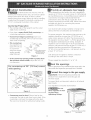
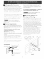
Seal the openings
Seal any openings in the wall behind the range and in the
floor under the range after gas supply line isinstalled.
the range to the gas supply
_mportant: Remove all packing material and
literature from range before connecting gas and
electrical supply.
To prevent leaks, put pipe joint sealant on all external
pipe threads.
Your regulator is in location shown below.
Do not
allow regulator to turn
on pipe when
tightening fittings.
PRESSUREREGULATOR
Figure 4 LOCATION

Connection to Pressure Regulator
The regulator is already installed on the appliance.
Do not make the connection too tight.
The regulator isdie cast. Overtightening may crack the
regulator resulting in a gas leak and possible fire or
explosion.
Manual GAS FLOW Pressure
Shutoff Flare _ Flare Regulator
Valve Union Union ¢
On, t t t
X._ Nipple Flexible NippleAccess
Off Connector
Cap
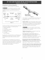
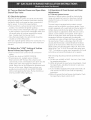
All connections must be wrench-tightened
Figure 5
Assemble the flexible connector from the gas supply pipe
to the pressure regulator in the following order:
1. manual shutoff valve
2. 1/2" nipple
3. 1/2" flare union adapter
4. flexible connector
5. 1/2" flare union adapter
6. 1/2" nipple
7. pressure regulator
Use pipe-joint compound made for use with Natural and
LP/Propane gas to seal all gas connections. If flexible
connectors are used, be certain connectors are not
kinked.
The supply line must be equipped with an approved
manual shutoff valve. This valve should be located in the
same room as the range and should be in a location that
allows ease of opening and closing. Do not block access
to the shutoff valve. Tile valve is for turning on or
shutting off gas to tile appliance.
li%
Shutoff Valve -
Open position
Figure 6
Once regulator is in place, open the shutoff valve in the
gas supply line, Wait a few minutes for gas to move
through the gas line.
Check for leaks. After connecting the range to the gas
supply, check the system for leaks with a manometer. If
a manometer is not available, turn on the gas supply and
use a liquid leak detector (or soap and water) at all
joints and connections to check for leaks.
Do not use a flame to check for leaks
from gas connections. Checking for leaks with a flame
may result in a fire or explosion.
Tighten a[[ connections as necessary to prevent gas
leakage in the range or supply line.
Check alignment of control knob valves after
connecting the appliance to the gas supply to be sure
the cooktop manifold pipe has not moved. A
misalignment could cause the valve stems to rub on the
control panel, resulting in a gas leak at the valve.
Disconnect this range and its individual manual
shutoff valve from the gas supply piping system during
any pressure testing of that system at test pressures
greater than 1/2 psig (3.5 kPa or 14" water column).
tsolate the range from the gas supply piping system
by closing its individual manual shutoff valve during any
pressure testing of the gas supply piping system at test
pressures equal to or lessthan 1/2 psig (3.5 kPa or 14"
water column).

LP/Propane Gas Conversion
appliance carl be usedwith Natural gasor LP/Propane
gas. It isshippedfrom the factory for usewith naturalgas.
If you wish to convert your range for use with LP/Propane
gas, use the supplied fixed orifices located in a bag
containing the literature marked "FOR LP/PROPANEGAS
CONVERSION." Follow the instructions packaged with
the orifices for surface, oven and broil burners
conversion.
The conversion must be performed by a qualified service
technician in accordance with the manufacturer's
instructions and all local codes and requirements. Failure
to follow these instructions could result in serious injury
or property damage. The qualified agency performing
this work assumes responsibility for the conversion.
Failure to make the appropriate
conversion can result in serious personal injury and
property damage.
Electrical Requirements
volt, 60 Hertz, properly grounded dedicated circuit
protected by a 15 amp circuit breaker or time delay fuse.
Note: Not recommended to be installed with a Ground
Fault Interrupt (GFI).
Do not use an extension cord with this range.
Grounding Instructions
IMPORTANT Please read carefully.
For personal safety, this appliance must be properly
grounded.
The power cord of this appliance is equipped with a 3-
prong (grounding) plug which mates with a standard 3-
prong grounding wall receptacle (see Figure 7) to
minimize the possibility of electric shock hazard from tile
appliance.
Tile wall receptacle and circuit should be checked by a
qualified electrician to make sure the receptacle is
properly grounded.
Where a standard 2-prong wall receptacle is installed, it
is the personal responsibility and obligation of the
consumer to have it replaced by a properly grounded 3-
prong wall receptacle.
Do not, under any circumstances, cut or remove the
third (ground) prong from the power cord.
Disconnect electrical supply cord from
wall receptacle before servicing cooktop.
Moving the Appliance for
Servicing and Cleaning
Turn off the range line fuse or circuit breakers at the main
power source, and turn off tile manual gas shut-off valve.
Make sure the range is (:old. Remove tile service drawer
(warmer drawer on some models) and open the oven door.
Lift the range at the front and slide it out of the cut-out
opening without creating undue strain on the flexible gas
conduit. Make sure not to pinch tile flexible gas conduit at
the back of the range when replacing the unit into the cut-
out opening. Replace the drawer, close tile door and switch
on tile electrical power and gas to tile range.
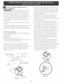
If the range regulator isconnected to rigid piping, the
regulator must be disconnected before moving the
appliance. If the range is equipped with a warmer
drawer, the regulator (:an be accessed through a side
panel. Remove the 2 screws securing the panel, then
remove the panel. Disconnect the regulator from the
piping. Reassemble in opposite order and manner of
removal (see Figure 8).
Preferred Method S
(DO not, under any /
Grounding type circumstances, cut,
wall receptaclE ,-q ._ remove, or bypas_
| the grounding /
......... _ Power supply cord with 3-
prong grounding plug.
Figure 7
LATERAL
DRAWER SIDE PANEL-
GLIDE WARMER
DO NOT REMOVE) (RH SIDE)
Figure 8

Range JnstaJJation
Standard JnstaJJation
1. The range cooktop overlaps the countertop at the
sides and the range rests on the floor. The cooktop
is 31 I/2"(!,27 cm) (81 cm) wide.
2. Install base cabinets 30" (762 cm) apart. Make sure
they are level before attaching cooktop. Shave
raised countertop edge to clear 31 1/2 "(1,27 cm)
wide range top rim.
3. Install cabinet doors 31 " (78.7 cm) rain. apart so
they will not interfere with range door opening.
4. Cut out countertop exactly as shown on page 1.
5. A backguard kit can be ordered through your
qualified servicer.
6. To provide an optimum installation, the top surface
of the countertop must be level and flat (lie on the
same plane) around the 3 sidesthat are adjacent to
range cooktop. Proper adjustments to make the top
flat should be made or gaps between tile countertop
and the range cooktop may occur.
7. _ To reduce the risk of damaging your
appliance, do not handle or manipulate it by the
cooktop. Manipulate the appliance with (:are.
8. Position range in front of the cabinet opening.
9. Make sure that the cooktop which overhangs the
countertop clears the countertop. If necessary, raise
the unit by lowering tile leveling legs.
10.Leve! the range (seesection I0), The floor where the
range isto be installed must be level. Follow the
instructions under "Leveling the Range-Models
Equipped with Leveling Legs" (figure ! 5).
11. Adjust leveling legs so that the underside of the
cooktop issitting on the countertop.
12. Carefully screw in the back leveling leg until the
cooktop overhang slightly touches the countertop.
Tile cooktop must not support the unit.
13. Then carefully screw in the front two leveling legs
(similar to ! 1) until the cooktop overhang touches
slightly the countertop.
14.1fthe range isnot level, pull unit out and readjust
leveling legs, or make sure floor is level.
Installation For 29" Cutout Wide Opening
1. You must replace the actual side trims by new and
smaller side trims. These new side trims can be
ordered through your authorized servicer.
2. Follow instructions supplied with new side trims for
side trim replacement.
3. Check if the countertop is prepared for 29" cutout
wide opening in "Countertop Preparation" section.
4. Install range as in the "Standard installation"
section above.
Installation With Backguard
Tile cutout depth of (21 3/4" (55.2 cm) Min., 22 1/8"
(56.2 cm) Max.) needs to be increased to 24"(10,16 cm)
(61 cm) when installing a backguard.
Installation With Side Panels
Install cabinet doors 31 " (78.7 cm) rain. apart so as not
to interfere with range door opening.
NOTE
Side panel, Backguard and End Panel kits can be ordered
through your dealer or authorized servicer.
Check Operation
Refer to the Use and Care Guide packaged with the
range for operating instructions and for care and cleaning
of your range.
Remove all packaging from the oven before testing.
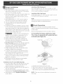
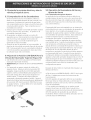
9.1 Install Burner Bases and Burner Caps
This range is equipped with sealed burners
as shown (see Figure 9).
Electrode __
Figure 9
a. Unpack burner bases and burner caps.
b. Place burner bases over each gas opening.
c. Make sure the burner is properly aligned and leveled.
Place burner caps over appropriate burner bases.
NOTE: There are no burner adjustments necessary on
this range.

9.2 Turn on Electrical Power and Open Main
Shutoff Gas Valve
9.3 Check the Igniters
Operation of electric igniters should be checked after
range and supply line connectors have been carefully
checked for leaks, and range has been connected to
electric power. To check for proper lighting:
a.Push in and turn a surface burner knob to the LITE
position. You will hear the igniter sparking.
b. The surface burner should light when gas is available
to the top burner. Each burner should light within four
(4) seconds after air has been purged from supply
lines. Visually check that burner has lit.
c. Once the burner lights, the control knob should be
rotated out of the LITEposition.
There are separate ignition devices for each burner. Try
each knob separately until all burner valves have been
checked.
9.4 Adjust the "LOW" Setting of Surface
Burner Valves (see Figure 10)
a.Push in and turn each control to LITEuntil burner
ignites.
b. Quickly turn knob to LOWEST POSITION.
c. If burner goes out, readjust valve asfollows:
Reset control to OFF. Remove the surface burner
control knob, insert a thin-bladed screw driver into the
hollow valve stem and engage the slotted screw
inside. Flame size can be increased or decreased with
the turn of the screw. Adjust flame until you can
quickly turn knob from LITEto LOWEST POSITION
without extinguishing the flame. Flame should be as
small as possible without going out.
9.5 Operation of Oven Burners and Oven
Adjustments
9.5.1 Electric Ignition Burners
Operation of electric: igniters should be checked after
range and supply line connectors have been carefully
checked for leaks, and range has been connected to
electric power.
The oven burner isequipped with an electric control
system aswell asan electric: oven burner igniter. If your
model is equipped with a waist-high broil burner igniter, it
will also have an electric: burner igniter. These control
systems require no adjustment. When the oven is set to
operate, current will flow to the igniter. It will "glow"
similar to a light bulb. When the igniter has reached a
temperature sufficient to ignite gas, the electrically
controlled oven valve will open and flame will appear at
the oven burner. There is a time lapse from 30 to 60
seconds after thermostat isturned ON before the flame
appears at the oven burner. When the oven reaches the
display setting, the glowing igniter will go off. The burner
flame will go "'out"' in 20 to 30 seconds after igniter goes
"OFF". To maintain any given oven temperature, this cycle
will continue aslong asthe display isset to operate.
After removing all packing materials and literature from
the oven;
a) Setthe oven to BAKE at 300%. See Use & Care Guide
for operating instructions.
b) Within 60 seconds the oven burner should ignite. Check
for proper flame, and allow the burner to cycle once.
Resetcontrols to off.
c) If your model isequipped with a high-waist broiler, set
oven to broil. See Use & Care Guide for operating
instructions.
d) Within 60 seconds the broil burner should ignite. Check
for proper flame. Reset controls to off.

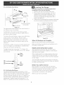
9,5,2AirShutter-OvenBurner
//"
Lower
Oven Baffle
(removable) ""
///
_Waisi-H gh
Burner
Leveling the Range
Level the range and set cooktop height before
installation in the cut-out opening.
1. Install an oven rack in the center of the oven.
2. Place a level on the rack (seefigure 13). Take 2
readings with the level placed diagonally in one
direction and then the other. Levelthe range, if
necessary, by adjusting the 4 leg levelers with a
wrench (seefigure 15).
3. Taking care to not damage the countertop, slide range
into cut-out opening and double check for levelness.
Lower Oven Bottom
(removable)
Air Shutter
Figure ! 1
The approximate flame length of tile oven burner is 1
inch (distinct inner, blue flame).
To determine if the oven burner flame is proper,
remove tile oven bottom and burner baffle and set
the oven to bake at 300°F.
To remove the oven bottom, remove oven hold down
screws at rear of oven bottom. Pull up at rear,
disengage front of oven bottom from oven front
frame, and pull the oven bottom out of tile oven.
Remove burner baffle so that burner flame can be
observed.
If the flame is yellow, increase air shutter opening size
(see "2" in Figure 12.) If tile flame is a distinct blue,
reduce tile air shutter opening size.
To adjust loosen lock screw (see "3" in Figure 12),
reposition air shutter, and tighten lock screw. Replace
oven bottom.
/ Oven
/_@-- Burner
/ Tube
_ Orifice
Hood
Figure 12
9.5,3 Air Shutter-BroiJ Burner
The approximate flame length of the burner is ! inch
(distinct inner, blue flame). To determine if the broil burner
flame is proper, set the oven to broil. If flame is yellow,
in(tease air shutter opening size. (see "2" in Figure 12 ) If
tile entire flame is a distinct blue, reduce the air shutter
opening size. To adjust, loosen lock screw (see "3" in
Figure 12), reposition air shutter, and tighten lock screw.
@
iii
j_
/ f
Figure 13
When All Hookups are Compmete
Make sure all controls are left in the OFF position.
Make sure the flow of combustion and ventilation air to
the range is unobstructed.
Modem and Serial Number Location
The serial plate is located on the oven front frame
behind the oven door (some models or on the drawer
side frame (some models).
When ordering parts for or making inquiries about your
range, always be sure to include the model and serial
numbers and a lot number or letter from tile serial plate
on your range.
Your serial plate also tells you the rating of the burners,
the type of fuel and tile pressure the range was adjusted
for when it left the factory.
Before You Call for Service
Read the Before You Call Checklist and operating
instructions in your Use and Care Guide. It may save
you time and expense. The list includes common
occurrences that are not the result of defective
workmanship or materials in this appliance.
Refer to your Use & Care Guide.

Anti-Tip Brackets JnstaJJation
To reduce the risk of tipping of the range,
the range must be secured to the floor by properly
installed anti-tip brackets and screws packed with the
range. Those parts are located in a plastic bag in the
oven. Failure to install the antPtip brackets will allow the
range to tip over if excessive weight is placed on an
open door or if a child climbs upon it. Serious injury
might result from spilled hot liquids or from the range
itself.
Follow the instructions below to install the antPtip
brackets.
If range is ever moved to a different location, the antPtip
brackets must also be moved and installed with the
range. To check for proper installation, see step 5.
Tools Required:
5/16" (0,79 cm) Nut driver or Flat Head Screwdriver
Adjustable Wrench
Electric Drill
3/16" (0,48 cm) Diameter Drill Bit
3/16" (0,48 cm) Diameter Masonry Drill Bit (if installing
in concrete)
Brackets attach to tile floor at the back of the range to
hold both rear leg levelers. When fastening to the floor,
be sure that screws do not penetrate electrical wiring or
plumbing. The screws provided will work in either wood
or concrete.
1. Unfold paper template and place it flat on the floor
with the back and side edges positioned exactly
where the back and sides of range will be located
when installed. (Use the diagram below to locate
brackets if template is not available.)
2. Mark on the floor the location of the 4 mounting
holes shown on the template. For easier installation,
3/16" (0.5 cm) diameter pilot holes !/2"(1,27 cm)
(1.3 cm) deep can be drilled into the floor.
3. Remove template and place brackets on floor with
turned up flange to the front. Line up holes in
brackets with marks on floor and attach with 4
screws provided. Brackets must be secured to solid
floor. If attaching to concrete floor, first drill 3/16"
(0.5 cm) dia. pilot holes using a masonry drill bit.
4. Level range if necessa% by adjusting 4 leg levelers
with wrench. (See Figure below.) A minimum
clearance of 1/8" (0.8 cm) is required between tile
bottom of the range and the rear leg levelers to
allow room for the antPtip brackets.
5. Slide range into place making sure rear legs are
trapped by ends of brackets. Range may need to be
shifted slightly to one side as it is being pushed back
to allow rear legs to align with brackets. You may
also grasp tile top rear edge of the range and
carefully attempt to tilt it forward to make sure
range is properly anchored.
Figure 14
Slide Back
Figure 15

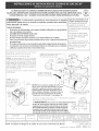
LA INSTALAaON Y EL SERVIaO DEBEN SER EFECTUADOS POR UN INSTALADOR
CAURCADO. IMPORTANTE: GUARDE ESTAS INSTRUCGONES PARA USO DEL INSPECTOR LOCAL
DE ELECTRIaDAD. LEA Y GUARDE ESTAS INSTRUCaONES PARA REFERENaA FUTURA.
Si [a informad6n contenida en este manual no es seguida
exactamente, puede ocurrir un incendio o expJosi6n causando daffos materiales,
[esi6n personal o [a muerte.
PARA SU SEGURDAD:
-- No almacene n[ utiJke gasolina u otros vapores y liqu[dos [nflamables en laproximMad de
_ste o de cuaJqu[er otto artefacto.
-- QUE DEBEHACER SIPERCmBEOLOR A GAS:
No trate de encender n[ng_n artefacto.
No toque n[ngun [nterruptor el@trko; no use nhg_n teJ_fono en su edificio.
Llame a su proveedor de gas desde el tel_fono de un vecino. Siga Jasinstrucciones deJ
proveedor de gas,
Si no [ogra comunicarse con su proveedor de gas, [lame a[ departamento de bomberos.
-- La instalad6n y el servMo de mantenim[ento deben set efectuados pot un [nstalador
calffkado, [a agenda de servkb o el proveedor de gas.
Aparatos Jnsta[ados en el
estado de Massachusetts;
Este Aparato s61o puede ser
instalado en el estado de
Massachusetts pot un plomero
o ajustador de gas [icenciado de
Massachusett.
Este aparato se debe instaiar
con un largo conector flexible
de gas de tres (3) pies/36
pulgadas_
Una vdvula manual de gas de
tipo manila de forma de "T" se
debe instalar en [a [inea de[
suministro de gas de este
aparato
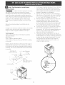
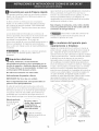
No pellizque el cord6n el6ctrico o el conducto
flexible de gas entre la estufa y la pared,
_(55.5 cm)" "
* Puerta
abi_,rta_ ;>_ /
(yea la ' A
nota) j
sentante o agente de servido autorizado, y
solidtar paneles [aterales opdonales (vea [a
figura a[ [ado} y despejar el reborde ancho de
[a codna ta[ como se muestra en [a secd6n
"Preparad6n de la Mesada " (vet p&gina 15).
6" x 6"'(15.2 cm X I52 cm) Area
recomendada para [a conexi6n de
pared de la Iigna de gas.
** Para los recortados menos que 22 7/8", el electrodomd, stico apareceria
ligeramente en el exterior del armario,
***IMPORTANTE: Para el torte a Io ancho (dimensi6n F) de m_s
de 30 1/16" (76,4 cm) para evitar que se rompa el vidrio, PARTE
asegurese que el artefacto est_ centrado en [a abertura DELANTERA
de [a mesada mientras [o presiona. Levante [as patas de DEL
nivelad6n hasta [a posici6n m&xima; inserte el artefacto ARMARIO
en [a mesada y [uego nivele. Asegurese de que [a unidad
est_ apoyada en [as patas de niveJaci6n y no en e[ vidrio [iso.
22 7/8" **
(58.1 crn) rain.
_23 114" _l
(59.05 cm) ma_.
_1 1/8"
[ (2,86 cm)
C. PROFUNDIDAD A LA F. ANCHURA DE G. PROFUNDIDAD DE H. ALTURA DEL |
FENTE DE LA ESTUFA RECORTADO*** RECORTADO MOSTRADOR
I
:_5318" (90 cm) - % 3/8" (92 cm) SO" (76,2 cm) 28 B/16" (71,9 cm) 30 ± 1116" 2I :_/4" (55,2 cm) Min 36" @1,4 cm) rlor/n_
(76,2 ±0,15cm) 22 1/8" (56,2 cm}Max. 35 318" (90cm) min
G La profundidad minima de recortado se aurnenta a 24" (61 cm) con el uso de un protector trasero. P/N 318201669 (0406) Rew B
NOTA: Se adjunta el diagrama de cables de esta cocina aJ final de este Jibreta. English - pages I-9
Espat_ol - p_ginas 10-I8
Diagrama de la instalaciOn alambrica - paginas 19-20

Notas importantes para e[ [nsta[ador
1. Lea todas las instrucciones contenidas en este manual
antes de instalar [a estufa.
2. Saque todo e[ material usado en el embalaje del
cornpartimiento del horno antes de conectar el
suministro electrico o de gas a la estufa.
3, Observe todos los c6digos y reglamentos pertinentes.
4, Deje estas instrucciones con el comprador.
Nota Importante para el Consumidor
Conserve estas instrucciones y el Manual del Usuario para
referencia futura.
INSTRUCCIONES DE
SEGURIDAD
Instalaci6n de esta estufa debe cumplir con todos los
c6digos locales, o en ausencia de c6digos locales con el
C6digo Nacional de Gas Combustible ANSI/NFPA .54--
Oltima edici6n,
El disef_o de esta estufa ha sido certificado por la CSA
Internaciona!, En este como en cualquier otro artefacto
que use gas y genere calor, hay ciertas precauciones de
seguridad que usted debe seguir, Estas ser_n encontradas
en el Manual del Usuario, lealo cuidadosamente.
Asegurese de que la estufa sea instalada y
conectada a tierra en forma apropiada pot un
instalador calificado o por un tecnico,
• Esta estufa debe set electricamente puesta a tierra
de acuerdo con los codigos locales, o en su
ausencia, con el C6digo Em@ctrico Naciona[ ANSI/
NFPA No, 70, ultima edici6n, Vea las instrucciones
para la puesta a tierra en la pSgina 4.
• Antes de instamar la estufa en un 5tea cuyo piso
este recubierto con [inbleo u otro tipo de piso
sintetico, aseg_rese de que estos puedan resistir
una temperatura de pot Io menos 90°F sobre la
temperatura arnbiental sin provocar encogimiento,
deforrnacion odecoIoraci6n, Noinstale laestufa
sobre una alfombra al menos que coloque una plancha
de material aislante de pot Io menos 1/4 pulgada,
entre la estufa y la alfombra.
• Todas las
estufas
pueden
volcarse.
Esto podria
resultar en
lesiones
personales,
Instale el
dispositivo
antivuelcos
que se ha
empacado
junto con
esta estufa.
Para reducir el riesgo de
que se vuelque la estufa,
hay que asegurarla
adecuadamente co!o
candole los soportes
antivuelco que se
proporcionan, Para
comprobar si estos estan
instalados y apretados en
su lugar como se debe,
ase el borde trasero
superior de la estufa y
cuidado samente incline la
hacia adelante para
asegurar que la estufa se
ancle.
Asegurese de que el material que recubre [as
paredes alrededor de la estufa, pueda resistir el
calor generado pot la estufa.
No obstruya et flujo del aire de combusti6n en [a
ventilaci6n de[ homo ni tampoco alrededor de la
base o debajo dem panel inferior demantero de la
estufa, Evite tocar lasaberturaso a'reascercanas de
la ventilaci6n, ya que pueden estar muy calientes
duranteelfuncionamientodel homo. La estufa
requiere aire fresco para la combusti6n apropiada de
los quemadores.
Nunca deje niffos solos o
desatendidos en un _rea donde un artefacto est_
siendo usado, A medida que los nifios crecen,
ensefieles el uso apropiado y de seguridad para todos los
artefactos. Nunca deje la puerta del homo abierta
cuando la estufa est5 desatendida.
No se pare, apoye o siente en [as
puertas o cajones de esta estufa pues puede resultar
en serias lesiones y puede tambi_n causar dafio a la
estufa,
• No aImacene articulos que puedan interesar a los
niffos en los gabinetes sobre la estufa. Los nil:los
pueden quemarse seriamente tratando de trepar a la
estufa para alcanzar estos articulos.
• Los gabinetes de almacenamiento sobre la estufa
deben set evitados, para etiminar [a necesidad de
tenet que pasar sobre los quemadores superiores
de la estufa para Ilegar a eHos,
Ajuste e[ tarnaffo de la llama de los quemadores
superiores de tal manera que @sta no sobrepase el
bordede los utensHios decocinar. La llama
excesiva es peligrosa.
• No use et homo como espacio de amrnacenaje. Esto
crear_ una situaci6n potencialmente peligrosa.
Nunca use [a estufa para calentar el cuarto, El uso
pro!ongado de la estufa sin la adecuada ventilaci6n
puede resultar peligroso.
No almacene ni utilice gasolina u otros vapores y
I[quidos inftamables en la proximidad de este o de
cuaIquier otto artefacto etectrico. Puede provocar
incendio o explosi6n.
• En caso de una interrupti6n del servicio electrico, es
posible de encender los quemadores de superficie a
mano. Para encender un quemador de superficie,
acerque un f6sforo encendido del cabezal de!
quemador, y gire delicadamente el bot6n de control de
superficie a LITE (encendido). Tener cuidado al
encender los quemadores a mano.
• Ajuste todos los controles a la posici6n "OFF"
(apagada) despu@s de haber hecho una operation
con tiempo programado,
PARA MODELOS AUTOLIMPIANTES:
Saque [a asadera, alimentos o cualquier otto
utensilio antes de usar el cido de autolimpieza det
homo, Limpietodoexceso de derrame dealimentos.
Siga las instrucciones de prelimpiado en el Manual del
Usuario.
o A diferencia de [agama est_ndar cocinas de gas,
ESTA PLANCHA DE COCINA NO ES MOVIBLE. No
11

Construcd6n de los armarios
_Para eliminar el riesgo de quemaduras e
incendios al tocar superficies sobrecalentadas, se debe
evitar colocar espacio para armarios de almacenamiento
sobrelasestufascon elementosaldescubierto. Sise
instalan armarios sobre la estufa, se pueden reducir tales
riesgos instlando una campana purificadora que se
proyecta horizontalemente un minimo de 5" (12.7 cm)
mas afuera de la parte inferior de los armarios.
Preparaci6n de[ Mostrador
Los lados de la superficie de la estufa se sobreponen a los
bordes recortados del mostrador
o
o
Si el mostrador es cuadrado (piano), no require ninguna
preparad6n
Si usted tiene un mostrador de frente formado
(encorvado), hay que resurar cada esquina frontal hasta
que este piano hasta 3/4" (I 9 cm) de la abertura,
Los mostradores
3/4"
embaHosados A_hura
pueden requerer un d_
hueco
recorte de 3/4" (1,9 rain.
31 1/2
cm) desde cada cm)MostradormoJdeado
esquina deJatera y/ oenazuJeio
recortado 3/4" (1.9
O un ap[anmiento (1.9 cm) cm} hacia atr'&s en [as
de los bordes I esquinasdefrentede
redondeados Figura 2 Ja abertura del
mostrador.
• S[ ta anchura de apertura de ta endmera es m&s
Para la Anchura existente del Recorte de el
29"(73.7 cm) :
Quite el 2,19" de
23/_?' material de frente a
la parte posteriora.
(3.2 cm)
I
moldeado o enazulejo
recortado 314" (1.9 cm) hada atras
en [a esquina de frente de [a
abertura del mostrador.
Figure 3
que ta anchura minima de recorte, ajusta el 3/
4"(I .9 cm) la dimensi6n..
• El mostrador debe estar nivelado. Ponga un nivel
sobre el mostrador, primero de un lado para otto y
despues de delante para atr_s. Si el mostrador no
est& nivelado, la estufa tampoco Io estara'. El homo
debe estar nivelado para resultados satisfactorios de
cocer. Los lados de la superficie de la estufa se
encajan por encima de los bordes de la abertura del
mostrador.
12
Propordone un suministro de gas
adecuado
Cuando se envia de la fabrica, Esta unidad ha sido
ajustada para operar con un m01tiple de admisi6n para
gas natural de 4" (!0.16 cm)(!.0 kPa). Un regulador de
presi6n convertible esta conectado a la valvula
distribuidora y DEBEser conectado con la tuberia del
suministro de gas. Si el juego de conversi6n del propano
LP/Propano se ha utilizado, sigue las instrucciones
proporcionadas eljuego para convertir el regulador de
presion al uso de LP/Propano.
se debe de tener cuidado durante la instalaciOn de la
estufa para no obstruir el flujo de aire de combusti6n y
ventilaci6n
Para la operacion apropriada, la maxima presiOn de
entrada al regulador no debe execeder la presion de una
columna de agua de 14"(35,56 cm) (3.5 kPa). La presion
de entrada al regulador debe set pot Io menos I " (.25
kPa) mas grande que la valvula distribuidora.Ejemplos: Si
regulador se pone para el gas natural con una presion de
4"(10,!6 cm), la presion de entrada al regulador debe
ser por Io menos 5"(12.60 cm); si el regulador se ha
convertido para gas LP/Propane 10"(25,4 cm) la presion
de entrada al regulador debe set pot Io menos 11"(27,9
cm).
Un examen de detection de fugas del aparato debe ser
realizado segOn las instrucciones en el paso 4.
La I[nea de fuente de gas debe ser de Y2" o de sA".
Selle las aperturas
sella todas las aperturas en la pared detras de la estufa y
en el suelo debajo de laestufa despu6s que la I[nea del
suministro de gas sea instalada.
Conecte la estufa al suministro de gas
Importante: Quite todo el material de embalaie y
literatura de la estufa antes de conectar el gas y la
fuente el_ctrica.
Para evitar fugas, aplique sellador de tuber[as en todas
las partes roscadas
machos (exterior) de la
tuber[a. El regulador se
encuentra en el lugar que
se muestra en la
illustration. (Figura 4)
No
permita que el
regulador gire sobre ta
tuberi_ a[ apretar [as
un[ones.
Figure 4
UBICACION DEL
REGULADOR DE PRESION

Conecte el Regulador de Presi6n
El regulador de presi6n esta ya instalada para la estufa.
No haga la conexi6n demasiado
apretada. El regulador es de die cast. El apretar
demasiado puede agrietar el regulador dando por
resultado una fuga de gas y un fuego o una explosi6n.
Valvula de FLUJO_DE_GAS Regulador
cierre Uni6n Uni6n de presi6n
manual ¢
Apagado flexible Tapa de
(off) entrada
Todas las conexiones deben ser apretadas con una Ilave
inglesa
Figura 5
Re0na el conector flexible del tubo del suministro de gas
al regulador de la presi6n en la orden siguiente:
1. Valvula de cierre manual
2, Boquilla de 1/2"
3. 1/2" Adaptador de uni6n
4. Conector flexible
5. 1/2" Adaptador de uni6n
6, Boquilla de 1/2"
7. regulador de presi6n
Use sellador para uniones de tuber[as hecho para el uso
de gas natural y LP/Propane para sellar todas las
conectiones de gas. Si se utilizan los conectadores
flexibles, asegures6 de que los conectadores no estan
enroscados.
La I[nea del suministro se debe de ser equipada de una
valvula de cierre manual aprobada. Esta valvula se debe
Iocalizar en el mismo cuarto que la estufa y debe estar
en una Iocalizacion que permita la facilidad de la
abertura y del cierre. No bloquee el acceso a la valvula.
La valvula es para encender o apagar el gas del aparato.
Abierta
Figure 6
Una vez que regulador esta en su lugar, abra la valvula
enlal[neadelsuministrodegas. Esperealgunos
minutos para que el gas pueda moverse a trav@sde la
I[nea de gas.
Compruebe para saber si hay fugas de gas. Despues
de conectar la estufa con la fuente de gas, compruebe
el electrodomestico para saber si hay fugas con un
manometro. Siun manOmetronoestadisponible, girela
fuente de gas y utilice un detector I[quido de fugas (o
jab6n y agua) en todos los empalmes y conexiones has
la comprobacion para fugas.
No utilice una llama para verificar fugas en las
conexiones de gas. Verificar para fugas con una llama
puede tener como resultado un fuego o la explosi6n.
Apriete todas las conexiones como necesario para
prevenir fugas de gas en la superficie de la estufa o en
la linea de suministro.
Verifique ta alinead6n de v&lvulas de bot6n de
control despues de conectar el aparato al suministro de
gas para estar seguro que el tubo de la plancha de
cocina no ha movido. Un desajuste podr[a causar que los
tallos de valvula se froten en el tablero de mandos,
teniendo como resultado una fuga de gas en la valvula.
Desconecte la estufa y su v_lvula de cierre manual
del sisterna de tuberia del surninistro de gas durante
cualquier prueba de presion de ese sistema a presiones
mayores de 1/2 psig (3,5 kPa o 14" columna de agua).
Aisle la estufa del sistema de tuberia del suministro
de gas cerrando su valvula de cierre manual durante
cualquier prueba de presion del sistema de tuberia del
suministro de gas prueba de presion iguala a o a menos
de 1/2 psig (3,5 kPa o 14" columna de agua).
13

Conversi6n para uso de Propano Liquido
Este aparato puede ser usado con gas natural o propano
Ifquido. Ha sido ajustado en la fabrica para operar con
gas natural solamente.
Si desea convertir su estufa para uso con propano
Ifquido, use los orificios provistos ubicados en el bolso
que contiene la literatura titulada "FOR LP/PROPANE
GAS CONVERSION." Siga las instrucciones que vienen
con los orificios.
que el enchufe se encuentra debidemente conectado a
tierra y polarizado. En lugares en los que aya un
enchufe de pared estandar de dos patillas, elcliente
tendr5 resposabilidad directa y la obligation de
reemplazarlo pot un enchufe de pared de tres patillas
debidemente cableado a tierra.
Bajo n[nguna drcunstanda, torte, retire o der[be
[a tercera pat[lla (de toma de t[erra} de[ cable de[
sum[n[stro de energ[a el_ctr[ca.
La conversion debe ser efectuado por un t6cnico de
servicio capacitado, de acuerdo con las instrucciones del
fabricante y con todos los codigos y requisitos de las
autoridades correspondentes. El no seguir las
instrucciones podr[a dar como resultado lesiones graves o
danosalapropiedad. EIorganismoautorizadopara
Ilevar a cabo este trabajo asume la responsabilidad de la
conversi6n.
_-!_ La falta de una conversi6n apropiada
puede resultar en lesiones graves y daflos a la
propiedad.
Requisitos el ctricos
120 volt[o, 60 Hertz[o, drcu[to deal[carlo
apropiadamente puestos a t[erra proteg[do pot un
drcuito de amperio o fusible de demora de tiempo
de 15 amp. Nota: no es recomendado [nstalar[o con
un tnterruptor (GFt) de puesta a tierra.
No utJlice una extensi6n con esta estufa.
Instrucciones de puesta a tierra
[MPORTANTE Pot favor lea con cuidado.
Para ta segur[dad personal, este aparato debe set
puesto a tierra apropiadamente.
El cable del suministro electrico de esta estufa esta
equipado con un enchufe de tres patillas (para puesta a
tierra) que coincida (:on un enchufe de pared estandar
con puesta a tierra de tres patillas para minimizar la
posibilidad que se produzcan descargas electricas.EI
cliente debera encargar a un t6cnico para asegurarse de
M_todo preferido _o torte, retire o
Enchufe de pared I deribe, bajo ninguna I
con toma de/L,..,I_II drcunstanda ' [a |
tierra [ patilla de [a toma de I
ra de[ enchufe
/
Cable de suministro
electrico con enchufe con
toma de tierra
Figure 7
Desenchufa el (:able del suministro de
energia el6ctrica del enchufe de pared antes de
mantener la plan(ha de cocina.
La mudanza del aparato para
reparaciones o limpieza
Apague la corriente el_ctrica a la estufa a la fuente de
poder principal, y apague la valvula de cierre manual de
gas. AsegOrese de que la estufa este fresca. Quite el
cajOn de servicio (el caj6n calentador en algunos modelos)
yabrelapuertadelhorno. Levantelafrentedelaestufa
y desl[cela fuera de la abertura sin (rear tensi6n
desmedida sobre el conducto flexible de gas. AsegOrese
de no pellizque el conducto flexible de gas detras de la
estufaalreemplazarlaunidadenlaabertura. Reemplace
el caj6n, cierre la puerta y enciende el gas y la corriente
electrica a la estufa. Elregulador debe desconectarse
antes de mover el aparato, si el regulador de la estufa se
conecta a una car]eria rigida. Si la estufa seequipa con
un cai6n calentador, el regulador puede accesarse
mediante un panel lateral de lado. Quite los dos tomillos
que aseguran el panel, entonces quite el panel.
Desconecte el regulador de la caneria. Reensamble en
orden inverso (consulte Figura 8).
EL PANEL LATERAL
EL DESLIZ DEL DE LADO o
CAJON CALENTADOR
(NO LO QUITE) (LADO DERECHO)
/
Figure 8
14

lnstaladOn de la estufa
tnstaladOn est_ndar
1. Lasuperficie de la estufa sesobrepone al mostrador por
los lados y la estufa descansa sobre el piso. La estufa es
de 31 1/2" (81 cm) de anchura.
2. Instale los gabinetes de base con una separaciOn de 30"
(76.2 cm). Aseg(_resede que seaplomen y sean
nivelados antes de juntar la estufa. Acepille la parte
levantada del borde del mostrador dejando espacio para
la superficie de la estufa de 31 1/2" (81 cm).
3. Instale las puertas de los gabinetes con una separaci6n
minima de 31" (78.7 cm) para que no obstruyan con la
puerta de la estufa al abrirse.
4. Recorte el mostrador exactamente segOnel dibujo en la
pagina I.
5. Un protector trasero puede pedirse mediante su
representante o agente de servicio autorizado.
6. Para proporcionar una instalaci6n Optima, la superficie
primera del mostrador debe ser nivelada y plana
alrededor de los 3 lados que estan adyacentes de la
parrilla de la estufa. Los ajustes Apropiados para
ponerlo piano deben de ser hechos o los espacios
entre el mostrador y la plancha de cocina pueden
ocurrir.
7. Rata reducir el riesgo de dar]ar su aparato, no maneia
ni Io manipula por la plancha de cocina. Manipule el
aparato con cuidado.
8. Posicione la estufa delante de la apertura del armario.
9. Asegurese que la plancha de cocinar que sobresale por
encima del mostrador sea mas alta quel mostrador. Si
necesario, levanta la unidad bajando las piemas que
nivelan.
10.Nivela la estufa (ve la seccion 10). El piso donde la
estufa debera set instalada debe set piano. Siga las
instrucciones "Nivelac:iOndelaestufa-Paralos
modelos equipado con las patas niveladoras (figura
15).
11.Ajuste alas patas niveladoras de manera que la parte
de abajo de la plancha de cocina esta apoyada contra
el mostrador.
12. Con cuidado enrosque los tornillos en la espalda que
tienne las patas niveladoras hasta que la plancha de
cocina toque ligeramente el mostrador. La plancha de
cocina no debe sostener la unidad.
13. Entonces enrosque (:on cuidado en la frente las dos
patas niveladoras (semejante a 11) hasta que la
plancha de cocina toque ligeramente el mostrador.
14. Si la estufa no es plana, tira la unidad fuera y aiusta
de nuevo las patas niveladoras, o asegurese de que el
piso este nivelado.
tnstalaciOn Para un Recorte de Abertura Ancho De 29"
1. Usted debe substituir los paneles laterales reales por
los paneles laterales nuevos y mas pequenos. Los
paneles laterales pueden ser pedidos con su
representante o agente de servicio autorizado.
2. Siga las instrucciones provistas con los nuevos ajustes
15
laterales para el reemplazo de los ajustes laterales.
3. yea si el mostrador esta preparado para un recorte de
avertura ancho de 29"' en la secciOn de la
"Preparad6n del mostrador".
4. Instale la estufa como en la secci6n "instaladon
_standar ".
tnstalaciOn con un protector trasero
La profundidad del recortado de (21 3/4"' (55.2 cm)Min.,
22 I/8" (56.2cm) Max.) necesita aumentarse a 24"(61 cm)
al instalar un protector trasero.
tlnstalaci6n con paneles [aterales
Instala las puertas del armario 31 "' (78,7 cm) min. aparte
para que no interfiren con la apertura de la puerta de la
estufa.
NOTA
Los paneles laterales, protectores trasero y el juego de
termino de panel se pueden ordenar por su representante
o agente de servicio autorizado.
Comprobad6n del
fundonamiento
Consulte el Manual del Usuario incluido con la estufa
para instrucciones de operaciOn y instrucciones para el
cuidado y limpieza de su estufa.
No toque Ioselementoso quemadores. Pueden estar
bastante calientes para causar quemaduras.
Quite todo el embalaje de la unidad antes de
comprobarla.
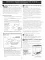
9,1 Instala las Bases y las tapas de los
Quemadores
Esta estufa esta equipada con quemadores
sellados como mostrado (yea la Figura 9).
a. Desembale las basas y las tapas de los quemadores.
b. Coloque una basa de quemador sobre cada abertura
de gas.
c. Asegurese que el
quemador est4
correctamente
alineado y nivelado.
Coloque lastapas de
losquemadores sobre
lascorrectas basas
de quemadores.
NOTA: No hate falta
ning0n ajuste de
quemador en esta
estufa.
Tapade quemador
Figure 9

9.2 Endende la corriente el_ctrica y abre la
valvula principal de derre,
9.3 Comprobad6n de los Encendedores
Elfuncionamiento de los encendedores electricos
debe ser comprobado despues de que la estufa y los
conectores a la tuber[a de suministro de gas hayan
sido comprobados para las fugas y la estufa haya sido
conectadael6ctricamente. Paracomprobarqueel
encendido sea correcto:
a. Empuje y gire un bott6n control del quemador superior
hastala position LITE(encender). Sepodrlao[rel
encendedor haciendo chispas.
b. El quemador se debera encender en cuatro (4)
segundos para un funcionamiento normal, despues de
que el aire haya sido purgado de la tuber[a de
suministro de gas. £ontrole visualmente que el
quemador se haya encendido.
c. Despu6s de que el quemador se haya encendido, la
plancha de cocina debe ser girada fuera de la position
LITE.£ada quemador tiene su encendedor individual.
£ontrole las perillas separadamente hasta que todas
lasvalvulas hayan sido controladas.
9.4 Ajuste de la Posici6n LOW (BAJA) Para la
V_lvula del Quemador Superior (Figura 12)
a. Gire el botton de control a la position LITE(encender)
hasta que el quemador encienda.
b. R&pidamente gire el botton de control a la POSICIONMAS
BAJA.
c. Si el quemador se apaga, reajuste la vdvula de la
siguiente forma: Mueva el control a la posici6n OFF
(apagada). Saque la perilla de control del quemador
superior, inserte un destornillador piano pequerlo en el
hueco del vastago del a valvula hasta enganchar el
tornillointerior. EItamaBodelallamapuedeser
aumentado o disminuido girando el tornillo. Ajuste el
tamaBo de la llama hasta que pueda pasar rapidamente
de la posici6n LITEhasta la posici6n MAS BAJAsin que
seapaguelallama. Lallamadebeserlomaspequerla
posible sin que se apague.
9.50peraci6n de Quemadores del Homo y
Ajustes de Homo
9.5.1 Quemadore de ignic6n electrica
La operaciOn de los encendores electricos debe de set
revisada despOesde que la cocina y los conectores de la
I[nea de suministro haya sido cuidadosamente revisada
para descartar fugas y que la cocina haya sido conectada
a la coriente electrica.
El quemador del horno esta equipado con un sistema de
control electrico as[ como un encendedor de quemador de
horno electrico. Sisu modelo esta equipado con un
quemador de asado central superior, tambi@ncontara (:on
un encendedor de quemador el6ctrico. Estos sistemas de
control no requieren ajustes. Cuando el horno esta
configurado para operar, la coriente fluira hacia el
encendedor y tendra un resplandor de manera similar a
una bombilla de luz. Cuando el encendedor a alcanzado
una temperatura suficiente para encender el gas, la
valvula del horno controlada el6ctricamente seabrira y el
fuego aparecera en el quemador del horno, hay un lapso
de tiempo de 30 a 60 segundos depues de que el
termostato se enciende y antes de que la llama aparezca
en el quemador del horno. Cuando el homo alcanza la
configuraci6n del dial, el encendedor resplandeciente se
apagara, la llama del quemador desaparecera por 20 a 30
segundos despu@sde que el encendedor se apage. Para
mantener qualquier temperatura de horno dada, este ciclo
continuara tanto como el dial (o visualizador) est@
configurado para operar.
Despues de retirar todos los materiales del empaque y la
literatura del homo:
a) Fije el homo en HORNEAR(BAKE) a 300°F. Vea la guia
de Uso y Cuidado para conocer las instrucciones de
funcionamiento.
b) En 60 segundos el quemador del homo seencendera.
Reviseque exista un fuego adecuado, y permita que el
quemador cumpla su ciclo una vez. Gire los controladores
hacia off (APAGADO).
c) Si su modelo esta equipado con un asador central
superior, fije el homo en ASAR.Vea la Guia de Uso y
Cuidado para conocer las instrucciones de funcionamento.
d) En 60 segundos el quemador de asar debe de
encenderse. Revisesi exista una llama adecuada. Gire los
controles hacia off (APAGADO).
Figure 10
16

9,5,20bturador [A[re-Quemadorde[homo
m" alturadela
._'_:__ _¢_-/ cintura
Deflector inferior . Obturado_-- - _.... r (modelos auto
(le,t haCilr_. / _de a,re ...... ,,mpiab,es)
Figure 11
La Iongitud aproximada de la llama del quemador del
horno es 1 pulgada (interior claro, llama azul). Para
determinar si la llama del quemador de homo es la
adecuada, retire el fondodel homoy el deflectordel
quemador i fiie el homo en la opci6n hornear a 300%.
Para retirar el fondo del homo, retire los tornillos de
ajuste del horno en la parte posteior del fondo del
horno, iale hacia arriba, desenganche el frente del
fondo del marco anterior del horno, y iale la base
hacia a fuera de este. retire el deflector del quemador
de manera que la llama del quemador pueda ser
observada.
Si la llama es de color amarillo, aumente el tamano de
la abertura del obturador de aire (Vea el tamar_lo "2"
en el grafico de abio). Si la llama es de azul claro,
reduzca el tamar_lo de la abertura del obturador de
aire. Para ajustar un tornillo de cierre flojo (Vea el
/ Tubos de[
quemador
de[ homo
Torni[[os de
seguridad _ _ @
Obturador Tapa de[
de aire _-- _ orificio
r-i
Figura 12
grafico "3" de ariba), wJe[va a colocar el obturador de
aire, y aiuste el tornillo de cierre. Reemplace el fondo
del horno.
9,5,30bturador de aire - Quemador de asado
La Iongitud aproximada de la llama del quemador de
asado es 1 pulgada (interior claro, llama azul). Para
determinar si la llama del quemador de asado es la
adecuada, porter el homo en la opcion asar.
Si la llama es de color amarillo, aumente el tamano de
la abertura del obturador de aire (Vea el tamar_lo "2"
en el grafico de abjo). Si la llama es de azul claro,
reduzca el tamano de la abertura del obturador de
aire, y ajuste el tornillo de cierre.
Nive[acidn de [a estufa
Nive[e [a estufa y ajuste [a a[tura de [a estufa antes
de insta[ar[a en [a abertura
@
/ j
Figure lS
1. Coloque una parilla del homo en el centro del homo.
2. Ponga un nivel sobre la parrilla (figura 10). Tome dos
lecturas con el nivel puesto diagonalmente en una
direction y despues en la otra. Nivele la estufa, si es
necesario, aiustando las4 patas niveladoras con una
Ilave de tuercas.
3. AsegOresede no danar al mostrador, deslice la estufa
dentro de la abertura del hueco y vuelva a verificar a la
nivelaci6n.
Despu_s de Terminar [a Instalaci6n
Aseg0rese de que todos los controles esten en la posici6n
OFF(apagada).
Aseg0rese de que e! fhir de! aire de combusti6n y de
ventilaci6n a la estufa no este obstruido.
Ubicad6n del N_mero de Modelo y de Serie
La placa con el n0mero de serie esta"ubicada en el
marco delantero del horno detra's de la puerta del homo
(algunos modelos) o detra's del caj6n (algunos modelos).
Cuando haga pedidos de repuestos o solicite informaci6n
con respecto a su estufa, este siempre seguro de incluir
el n0mero de mode!o y de serie y el n0mero o letra del
Iote de la plata de serie de su estufa.
La placa con e! n0mero de serie tambien le da la potencia
nominal de los quemadores, e! tipo de combustible y la
presi6n a la cual fue ajustada la estufa en la f_brica.
Antes de Llamar a[ Servic[o
Lea la secci6n Evite Llamadas de Servicio en su Manual del
Usuario. Esto le podra"ahorrar tiempo y gastos. Esta lista
incluye ocurrencias comunes que no son el resultado de
defectos de materiales o fabricaci6n de este artefacto.
Lea la garantia y la informaci6n sobre e! servicio en su
Manual de! Usuario para obtener e! n0mero de telefono
gratuitoyla direcci6n delservicio. Por favorllameo
escriba si tiene preguntas acerca de su estufa o necesita
repuestos. Refere a el gu[o Uso y Cuido.
17

Para los mode[os equipado con [as
patas nive[adoras.
__ Para reducir el riesgo de inclinaci6n de
la cocina, esta debe ser asegurada hacia el piso con las
fijaciones de antiqnclinaciOn y los tornillos que vienen
con la cocina. Estos componentes se encuentran en el
horno. Si no instala las fiiaciones, corre el riesgo que su
cocina pueda inclinarse si pone demasiado peso en ella
o si un niflo sube sobre 6sta. Esto podria ocasionar
graves heridas causadas por liquidos calientes o por la
propia cocina.
Siga estasinstrucciones para instalar las fijaciones de anti-
inclinacion.
Si la cocina estrasladada a otro lugar, las fiiaciones de anti-
inclination deben tambi6n set trasladados con la cocina.
Para controlar la instalaci6n apropiada, yea el paso m]mero
5.
Herramientas Necesarias:
Llave de tuerca de 5/!6"(0,79 cm) o destornillador para
tornillos de cabeza plana
Llave inglesa
Taladro electrico
Broca de 3/16"(0,48 cm) de diametro
Broca para taladro de mamposteria de 3/16"(0,48 cm) de
dia. (si se esta instalando en concreto)
Los soportes se fijan al suelo en la parte trasera de la
estufa para suietar ambos niveladores de las patas
traseras. Cuando los est6 instalando al piso, aseg(_rese de
que los tornillos no penetren el alambrado el6ctrico o
plomerfa. Lostornillos provistos pueden utilizarse en
madera o concreto.
1. Desdoble la plantilla de papel y col6quela plana en
el piso con los hordes laterales y el trasero colocados
exactamente donde la parte trasera y los lados de la
estufa seran colocados cuando sea instalada. (Use el
diagrama siguiente para ubicar los soportes si no se
dispone de la plantilla).
2. Marque en el piso la ubicaci6n de los 4 aguieros de
montaje como se muestra en la plantilla. Para
facilitar la instalaci6n, se pueden taladrar aguieros
piloto de 3/16" (0.5 cm) de dia. y 1/2" (1.3 cm) de
profundidad en el piso.
3. Saque la plantilla y coloque los soportes en el piso
con la brida hacia arriba dirigida hacia el frente.
Alinee los agujeros en los soportes con las marcas en
el piso y suiete con los 4 tornillos provistos. Los
soportes deben estar asegurados al piso firme. Si se
va a instalar en piso de concreto, primero debe
taladrar aguieros guia de 3/16" (0.5 cm) de diametro
usando una broca para taladro de mamposteria.
4. Nivele la estufa si es necesario aiustando las cuatro
patas niveladoras (:on una Ilave (Vet la Figura 12
abajo). Se requiere un espacio libre minimo de I/8"
(0.8 cm) entre la parte inferior de la estufa y los
niveladores de las patas traseras para deiar espacio
para los soportes antivuelco.
5. Deslice la estufa a su lugar asegurandose de que las
patas traseras est6n sujetas pot los extremos de los
soportes. La estufa puede necesitar set movida
ligeramente a un lado cuando esta siendo empujada
hacia atras para permitir que las patas se alineen con
los soportes. Usted tambi_n puede asir el horde
trasero de la cima de la estufa y cuidadosamente
intentar voltearla para asegurarse de que la estufa
sea adecuadamente anclada.
Borde de atras de [a Soporte antivuelco
estufa o pared trasera
3/4" Typ.
Y2"(13 cm)_ "'---._(1,9cm) Typ
......... 4
• _(Anchura trasera de la
Soporte •.... _f/ estufa con los lados)
antivuelco
hacia arras
Figura 11
(
Figura 12
18

SAKE VALVE N
VA VUL_ DE I ORNEAR
SAKE ]GNI rER DE[ENDEUR DE CUISSON W 6
ENCENDIDO DE HORNEAR i
ALLUHEUR CU I SSON i I
rT ........ i
ELEC RONIC OVEN CONIROL v 14 _ _ Iw _4 I
CONIROL ELEC AONIC0 DE HOAN0 o\.,__ t_} } i<_--
J\
A
ELEC ONiOUE sRo, v "
re, R" /'_r" _X VALVULA DE ASA
L_ _uU ur_ \/ _ DETEI\DEUR E GR L AGE _q
N" fiRS L IGNITER <<( O
£NCENDIDO DE _S/_R F ----3 l
%! UHEUR R II { /k_ Cx , l
BI 4 i
I OO( ©QOOOOO©OO,_})© _, 6 l
i i _ Y a RI4 i
v ,_ I I _ i
_ Vlay14 _L :L _ TIIERF 4OSTa,T F*,_N NO O
(_ __ l l 'ERHOS A 0 MS O_ EVEN ADOi l
i i TllERHOST&T _/OTEUR VENT L_T UR
, , -
- I I R 4 R 4 J-!-_ A 1 4 Ilj 4 I
TEMPERA ! k;RE PROSE l i
SONDA DE E_'II EIR!_ U _A l O O O
b,OND I ERH I OUE l V l
BL/W 14 i %' 14 _ .... _d :4 ....................
I O /EN AHP
• I OVEN L/IMP '._ 7C ' Z DE ORNO
D/ [4 NO _ i ATCH qOTOR td IN ERRUPfOR )E IUZ S H{RNO _['AHPE FOUR
S/_ A _ _ I PIC_OR DE CERRSJO NrEI:_RUIS EU_ LAHaE FOUR -
z' HC UR v_R C IGY /4/_8_j _ BK !4Nt _; 14 /,/ 14 W 14 R 4
NO NC ,;/BK 14
o
L
R 6
/\
/\
R 6
BRKE IGNITER
ENCENDiDO DE !IORNEAR
E_ECTRONiC OVEN CONTRO[
CONTRO[ EIECTRONICO DE HORNO
CONTR01E EiECTRONIOUE
ES 335 6£5
15 i
_C OOOOOrbc)('O001
, i i
7y _1• V 14 L
'
I vt4 i
FEHPERA FLJRE PROSE i
SONDA DE E_IPER/_TURA
SONDE rl_ RH SUE
i
NC
LATCH M T . i
MOTOR DE CESSOJO "_'O
NO [EIJR VERROU
NO
BR/'d 14
Y 14
BL 14
17 14
W 14
LA [Cli HO ISR
HOTOR DE CEAROJO
HO1EUR VERRSU
OdEN IAIqR
LUZ DE HORNS
LAHPE FOUR
Bd 14 (41) '<_ 14
TJ_d
_,_<EV,*LVE N L
//A VJI A i] IICRN{ AR _ {_ F,_ 6
DET NDEUR DE CL ]55ON _\ j
DETENDEUR DE GR]ii AGE
\_ BROIl IGNITER
IENCENDIDO DE ASAR f i
w 14
td i 4
R 6
W 6
F¢ 14
FAN Horc}R
MOTOR DE VENT]LADOR
HOTEUR VENTIIATEtiR
W %4
SW A:
LATCH SWITCH
INTERRUPTOR DE CERROJO
INTEFtI:_UPrEUR VERROU
31827i900 _E'V: A
P : /
i THERMOSTAT
/E!RMOSIA]O
TblERHOST&T
19

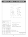
COOKTOP C]RCUiT/CiRCU]TO DE PLANCHA DE COCiNAR/
CIRCUIt IABLE CUI%SON
OP BURNER IGNI dl
O;EkCAD£SR D7 ENCEND DO SUPER)OR
BOUGIE D" ALLL_,eGd BRULdU*a
i
i
fOP BUqNER IGN [FR _L
OUE_IA_R DE NCENO_DO b._ERIOR
BObG IE D" ALLOMAGE 8RU, E_
_ R[GH[ REAR
'_ I JGNSW
]Iq/ENC ]RASERO
DERECI IO
INTER ALLUM
R 4
R 14
>> £!_ L
,# 14
NN
//
WARN]NG/AV/S0/AVERTISSEMENT
DiSCONNLCT POWER BEFORE SERV]CLNG UNLT/
DESCONECTE LA ENERGiA ANTES DE REALiZAR
EL MANIEN]MIENFO DEL ELECIRODONESF]CO/
COUPER LE COI2RAN[ AVANI D'EFFECIUER
LA REPARA]ION
w 10
_#IRES COLOR NO /NO DE COLOR DE ALAHBRE/NO COL,LEUR DES F LS
COl OR CODE/COD ] GOS/CODE COU E JR
D_ IBLJE/AdUL/_LLJ IP_I Ff _E_/_LJ3L£/_OL R_RE
BR I 8RO_N/_IORENO/BR r,_ I R IRED/NOJO/F_OUGE
c j COPPER/COB_/C_ ! VR_ i j I_N/ OS AOO/FA_:
G jGr_EN/VERDE/VERT IV jVIOI E F/VIOl E FA/VIEX El
QY jGRAY/GRAY/GR]S 1/4 l,_ I IE/BI /_NCO/BI ANO
O i ORfSNGE/NARAJ_C/O_ANGE I Y I Y!_l _O',#/APIAR I I O/.JAUN£
CAUT ON :
AlJl A[ '_/]R£S PFilOFi I0 DI CONN CFION WII£N _5EF/_,'IC[N(} {(}NTRO i
W_R )NG ERROR CAN CAU5_ I HPROPER AND DANGEROUS OPERAT }ON
VER )FY PROPER OPERAT iON AFTER SERV I C ING
AViSO
ETIQUETE TOOOS LOS ALAMBRES ANTES DE EESCONECTAR P_R
_A I ZAR ( I MANIENIM INIO [}1 I O_ CON ROI I _ EFtR()Fe D
ALAMBRA E PUEDE CACSAR UN FUNCION/'H]ENTO }NCORRECTO
Y PEL ]GROS0 VERI QUE S I EL FUN8 )ONAM] ENTO ESTA
COR_CTO DESPUES DEL MANTEN!MIENTO
AVER ISSEMEN1 :
lot E_ { IAOJf F I _VAN )(k_ANCI E_FNF D{ CEJX C I LNE NIl( L;l_ [E
BRANCHEKgNT PEUT CAUSER UNE OPERATION DANGEREUSE VER)F]ER LE BON
FONC FIONSqEMENT DE • APPARE IL !_PFES /OGLE REPARA ION
N0 E/NO FA/N0 FE:
CI_CUI_ SHOWN _I_H ALL CONI_OLS SEt T0 '0Fe"
OVdN DOOR CLDSED AND UNLOCKE{[}
(!!IC IFRCUI T0 (ZS_A I!USTF_ADO 80N TODOS ! OS CON_ROI ES A 'OFF
(APAGAD01 PUERTA DE Ii0RNO ABIERTA Y NO CERRADA
LE SCHEMA ELECTR)OUE INDIQOE OUE LES COHHANDES SONF
A "ARRET" QUE LA PORTE EST FERULE E F NON VERROU]LLEE
31827 900 RE\/: A
P:2
2O
-
 1
1
-
 2
2
-
 3
3
-
 4
4
-
 5
5
-
 6
6
-
 7
7
-
 8
8
-
 9
9
-
 10
10
-
 11
11
-
 12
12
-
 13
13
-
 14
14
-
 15
15
-
 16
16
-
 17
17
-
 18
18
-
 19
19
-
 20
20


Frigidaire FGS379DSA Guía de instalación
- Categoría
- Microondas
- Tipo
- Guía de instalación
En otros idiomas
Documentos relacionados
Otros documentos
-
Electrolux 318201775 Manual de usuario
-
-
Kenmore Pro 79079613801 Guía de instalación
-
Kenmore Elite 79036714504 Guía de instalación
-
-
Electrolux 318201778 Manual de usuario
-
-
 Kenmore Elite 79036603601 Guía de instalación
-
Kenmore 79031032802 Guía de instalación
-
Tappan TGF657BFW9 Guía de instalación
