Hitachi PR-25B Instrucciones de operación
- Categoría
- Martillos perforadores
- Tipo
- Instrucciones de operación
Este manual también es adecuado para

PR-38E
Rotary Hammer
Martillo perforador
สว่านเจาะกระแทกโรตารี
PR-25B
•
PR-38E
Handling instructions
Instrucciones de manejo
คู่มือการใช้งาน
Read through carefully and understand these instructions before use.
Leer cuidadosamente y comprender estas instrucciones antes del uso.
โปรดอ่านโดยละเอียดและทำความเข้าใจก่อนใช้งาน

1
1-1 1-2
23
45
67
89
(PR-25B) (PR-38E)
1
2
3
1
2
4
5
6
7
8
9
0
!
@
#
$
%
^

2
10
12
14
16
11
13
15
17
&
*
(
)
&
q
&
*
w
e
r
t

3
English Español
ไทย
1
Tool Herramienta
เครื
องมือ
2
Retainer Retenedor
ตัวคีบ
3
Front cover Cubierta delantera
ครอบหน้า
4
Stopper Retén
สต็อปเปอร์
5
Plug Tapón
จุก
6
Snap off this portion after
driving in the self-drilling
anchor.
Sacar esta parte luego
de colocar el anclaje de
autoperforación.
ดึงส
่
วนนี
ออกหลังจากหมุนเข้า
ในสกรูพุกแบบเจาะด้วยตัวเอง
7
Turning handle Manija para girar
มือหมุน
8
Anchor adapter Adaptador de anclaje
ตัวปรับสกรูพุก
9
Striking by hammer drill Golpear con martillo
เคาะด้วยสว่านกระแทก
0
Move right and left.
Mover a la derecha e
izquierda
เลื
อนไปทางซ้ายและขวา
!
Hole depth Profundidad del orifi cio
ความลึกของรู
@
Drift key Cuña saca mecha
ประแจงัด
#
Wrench out Extraer
งัดออก
$
Taper shank adapter
Adaptador de la espiga
ahusada
ตัวปรับเพลาเทเปอร์
%
Drill bit (with tapered
shank)
Broca de barrena (barrena
ahusada)
หัวสว่าน (มีเพลาเทเปอร์)
^
Hole depth indicating
groove:
A standard depth
conforming to the anchor
outside diameter is
indicated.
Ranura que indica la
profundidad del orifi cio:
Indica una profundidad
estándar de acuerdo con
el diámetro exterior del
perno de anclaje.
ความลึกของรูแสดงด้วยร่อง:
แสดงความลึกมาตรฐานที
ตรง
กับเส
้
นผ่านศูนย์กลางภายนอก
ของสกรูพุก
&
Core bit Barrena tubular
จานเจียรเพชรคอนกรีต
*
Core bit shank
Espiga de la barrena
tubular
เพลาจานเจียรเพชรคอนกรีต
(
Center pin Pasador central
เดือยนำ
)
Guide plate Placa guía
แผ่งราง
q
Core bit tip Punta de barrena tubular
ปลายจานเจียรเพชรคอนกรีต
w
Oil gauge
Check the oil quantity by
holding the body upright.
Indicador de aceite
Compruebe la cantidad de
aceite sujetando el cuerpo
recto.
เข็มนำมัน
ตรวจปริมาณนำมันโดยจับตัว
เครื
องให้หันขึ
น
e
Resupply oil when the oil
level drops to less than
approx. 3 mm.
Cuando el nivel de aceite
disminuya a menos de
unos 3 mm, rellene con
aceite.
เติมนำมันเมื
อระดับนำมัน
ลดลงประมาณ 3 มม.
r
Wear limit Limite de desgaste
ขอบเขตการส
ึ
กหรอ
t
No. of carbon brush No. de escobilla de carbón
จำนวนแปรงถ่าน

English
4
GENERAL SAFETY RULES
WARNING!
Read all instructions
Failure to follow all instructions listed below may result in
electric shock, fi re and/or serious injury.
The term “power tool” in all of the warnings listed below
refers to your mains operated (corded) power tool or battery
operated (cordless) power tool.
SAVE THESE INSTRUCTIONS
1) Work area
a) Keep work area clean and well lit.
Cluttered and dark areas invite accidents.
b) Do not operate power tools in explosive
atmospheres, such as in the presence of
fl ammable liquids, gases or dust.
Power tools create sparks which may ignite the dust
of fumes.
c) Keep children and bystanders away while
operating a power tool.
Distractions can cause you to lose control.
2) Electrical safety
a) Power tool plugs must match the outlet.
Never modify the plug in any way.
Do not use any adapter plugs with earthed
(grounded) power tools.
Unmodifi ed plugs and matching outlets will reduce
risk of electric shock.
b) Avoid body contact with earthed or grounded
surfaces such as pipes, radiators, ranges and
refrigerators.
There is an increased risk of electric shock if your
body is earthed or grounded.
c) Do not expose power tools to rain or wet
conditions.
Water entering a power tool will increase the risk of
electric shock.
d) Do not abuse the cord. Never use the cord for
carrying, pulling or unplugging the power tool.
Keep cord away from heat, oil, sharp edges or
moving parts.
Damaged or entangled cords increase the risk of
electric shock.
e) When operating a power tool outdoors, use an
extension cord suitable for outdoor use.
Use of a cord suitable for outdoor use reduces the
risk of electric shock.
3) Personal safety
a) Stay alert, watch what you are doing and use
common sense when operating a power tool.
Do not use a power tool while you are tired
or under the infl uence of drugs, alcohol or
medication.
A moment of inattention while operating power tools
may result in serious personal injury.
b) Use safety equipment. Always wear eye
protection.
Safety equipment such as dust mask, non-skid
safety shoes, hard hat, or hearing protection used for
appropriate conditions will reduce personal injuries.
c) Avoid accidental starting. Ensure the switch is in
the off position before plugging in.
Carrying power tools with your fi nger on the switch or
plugging in power tools that have the switch on invites
accidents.
d) Remove any adjusting key or wrench before
turning the power tool on.
A wrench or a key left attached to a rotating part of the
power tool may result in personal injury.
e) Do not overreach. Keep proper footing and
balance at all times.
This enables better control of the power tool in
unexpected situations.
f) Dress properly. Do not wear loose clothing or
jewellery. Keep your hair, clothing and gloves
away from moving parts.
Loose clothes, jewellery or long hair can be caught in
moving parts.
g) If devices are provided for the connection of
dust extraction and collection facilities, ensure
these are connected and properly used.
Use of these devices can reduce dust related
hazards.
4) Power tool use and care
a) Do not force the power tool. Use the correct
power tool for your application.
The correct power tool will do the job better and safer
at the rate for which it was designed.
b) Do not use the power tool if the switch does not
turn it on and off .
Any power tool that cannot be controlled with the
switch is dangerous and must be repaired.
c) Disconnect the plug from the power source
before making any adjustments, changing
accessories, or storing power tools.
Such preventive safety measures reduce the risk of
starting the power tool accidentally.
d) Store idle power tools out of the reach of children
and do not allow persons unfamiliar with the
power tool or these instructions to operate the
power tool.
Power tools are dangerous in the hands of untrained
users.
e) Maintain power tools. Check for misalignment or
binding of moving parts, breakage of parts and
any other condition that may aff
ect the power
tools’ operation.
If damaged, have the power tool repaired before
use.
Many accidents are caused by poorly maintained
power tools.
f) Keep cutting tools sharp and clean.
Properly maintained cutting tools with sharp cutting
edges are less likely to bind and are easier to
control.
g) Use the power tool, accessories and tool bits
etc., in accordance with these instructions and
in the manner intended for the particular type
of power tool, taking into account the working
conditions and the work to be performed.
Use of the power tool for operations diff erent from
intended could result in a hazardous situation.
5) Service
a) Have your power tool serviced by a qualifi ed
repair person using only identical replacement
parts.
This will ensure that the safety of the power tool is
maintained.
PRECAUTION
Keep children and infi rm persons away.
When not in use, tools should be stored out of reach of
children and infi rm persons.

5
English
ROTARY HAMMER SAFETY WARNINGS
1. Wear ear protectors.
Exposure to noise can cause hearing loss.
2. Use auxiliary handles supplied with the tool.
Loss of control can cause personal injury.
3. Wear protective glasses to protect your eyes.
4. Properly set the bit holder.
5. Do not touch the bit during or immediately after operation.
The bit becomes very hot during operation and could
cause
serious burns.
○ Drill bit
(tapered shank, for drilling anchor holes)
Drill external diam. Code No.
11 mm 944460
12 mm 944461
14.3 mm 944462
14.5 mm 944500
PR-25B
standard accessory
17.5 mm 944463
21.5 mm 944464
○ Taper shank adapter
(for installing taper shank drill)
Drill diam.
to be used
11, 12, 14.3, 17.5 mm 21.5 mm
Code No. 944475 944476
○ Cotter (Code No. 944477)
(for taper shank adapter)
○ Core bit
(with guide plate, not applicable to cores 25 mm and
29 mm)
6. Safe operation depends on one's stable posture.
7. At the start of work, confi rm the oil supply and screw
tightening.
8. When working at a highly elevated location, pay attention
to articles and persons below.
9. Before starting to break, chip or drill into a wall, fl oor or
ceiling, thoroughly
confi rm that such items as electric
cables or conduits are not buried inside.
10. Wear a dust mask
Do not inhale the harmful dusts generated in drilling or
chiseling operation. The dust can endanger the health of
yourself and bystanders.
SPECIFICATIONS
Model PR-25B PR-38E
Voltage (by areas)* (110 V, 115 V, 120 V, 127 V, 220 V, 230 V, 240 V)
Power Input* 1050 W 1050 W
No-load speed 750 / min. 400 / min.
Full-load impact rate 3000 / min. 3000 / min.
Capacity: Drill bit
Core bit
25 mm
64 mm
38 mm
105 mm
Weight (without cord) 7.3 kg 7.5 kg
* Be sure to check the nameplate on product as it is subject to change by areas.
STANDARD ACCESSORIES
PR-25B
(1) Case .............................................................................1
(2) Side handle ...................................................................1
(3) Oil feeder ......................................................................1
(4) Wrench .........................................................................1
(5) Syringe ..........................................................................1
(6) Taper shank adapter .....................................................1
(7) Drill bit (tapered shank 14.5 mm) ..................................1
(8) Cotter
PR-38E
(1) Case .............................................................................1
(2) Side Handle ..................................................................1
(3) Oil Feeder .....................................................................1
(4) Wrench .........................................................................1
Standard accessories are subject to change without notice.
OPTIONAL ACCESSORIES (sold separately)
○ Drill bit
(hexagonal shank, for drilling through-holes)
Drill external
diam.
Code No.
(
total length
)
280 mm
Code No.
(
total length
)
505 mm
16 mm 944465 944470
PR-25B
PR-38E
19 mm 944466 944471
22 mm 944467 944472
25 mm 944468 944473
28 mm 944495 944496
PR-38E32 mm 944469 944474
38 mm 944545 944546

English
6
Dø (mm) Code No.
25 955994
PR-25B
PR-38E
29 955995
32 955996
35 955998
38 956000
45 955154
54 955155
64 956002
79 955157
PR-38E94 956004
105 955159
○ Core bit shank
Code No. 955163
Applied to core bits above Dø 38 mm.
Code No. 956008
Applied to core bits below Dø 35 mm.
○ Center pin
Code No. 955165
Code No. 956009
for core bit Dø 32 mm and 35 mm
NOTE
Do not use it for core bit Dø 25 mm and 29 mm.
○ Drift key
(for self-drilling anchors)
(Code No. 944574)
○ Turning handle
(for self-drilling anchors)
(Code No. 944573)
○ Anchor adapter
(for self-drilling anchors)
NOTE
A turning handle is used with this anchor adapter.
Anchor size
For rotation and impact For impact
Code No. Code No.
w1/4 (No. 20) 944593 944568
w5/16 (No. 25) 944594 944569
w3/8 (No. 30) 944595 944570
w1/2 (No. 40) 944596 944571
w5/8 (No. 50) 944597 944572
○ Bull point
(for crushing)
Total length 280 mm 450 mm
Code No. 944566 944583
○ Cold chisel
(for grooving and squaring)
Total length 280 mm 450 mm
Code No. 944567 944584
○ Syringe
(for removing chips after making holes)
(Code No. 944575)
○ Cutter
(for crushing asphalt)
(Code No. 955180)
○ Rammer
(for tamping sand and gravel)
(Code No. 955181)
○ Bush hammer
(for roughing concrete and stone surfaces)
(Code No. 955183)

7
English
○ Shank
(for rammer and bush hammer)
(Code No. 955186)
• Bush hammer + Shank
• Rammer + Shank
○ Scoop
(for digging ground in various foundation work)
(Code No. 944967)
○ Rotary hammer oil (one liter)
(Code No. 955009)
Optional accessories are subject to change without notice.
APPLICATIONS
○ Drilling holes in concrete
○ Drilling anchor bolt holes
○ Crushing concrete, chipping, digging, and squaring (by
applying optional accessories)
(Application Examples)
Installation of piping and wiring, sanitary facility
installation, machinery installation, water supply and
drainage work, interior jobs, harbor facilities and other
civil engineering work.
PRIOR TO OPERATION
1. Power source
Ensure that the power source to be utilized conforms
to the power requirements specifi ed on the product
nameplate.
2. Grounding
This tool should be grounded while in use to protect the
operator from electric shock. The tool is equipped with a
three conductor cord and grounding type plug to fi t the
proper grounding type receptacle. The green (or green
and yellow) conductor in the cord is the grounding wire.
Never connect the green (or green and yellow) wire to a
live terminal.
3. Power switch
Ensure that the power switch is in the OFF position. If
the plug is connected to a power receptacle
while the
power switch is in the ON position, the power tool will
start operating immediately, which could cause a serious
accident.
4. Extension cord
When the work area is removed from the power source,
use an extension cord of suffi cient thickness and rated
capacity. The extension cord should be kept as short as
practicable.
5. Feeding oil (refer to the paragraph on oil feeding,
page 7)
Prior to using the power tool, remove the oil gauge and
do not fail the oil tank
with the provided oil. (Although the
oil tank is built in, it contains only a small volume of oil
when shipped from the Hitachi Works.)
6. Mounting a tool
NOTE
When handling drill bits, bull point, cold chisel and other
accessories, Hitachi standard tools are recommended
for better operation.
PR-25B
(1) Raise the retainer and insert the
shank portion of a drill bit
into the hexagonal hole on the front cover until it reaches
the extremity. (Fig. 1-1)
(2) By slightly tapping the top of the bit holder with a wooden
mallet, replace the bit holder to grip the bit fi rmly.
PR-38E
(1) Pushing the stopper to arrow A
direction, turning the
retainer to arrow B direction.
After, insert the tool shank into the hexagon hole on the
front cover. (Fig. 1-2)
(2) Pushing the stopper to arrow A direction, turning the
retainer to arrow B in the opposite direction. After, apart
the stopper.
NOTE
When dismounting the bull points,
reverse the procedures
described above.
HOW TO USE THE ROTARY HAMMER
1. How to drill holes
(1) Pull the switch trigger after applying the drill bit tip to the
drilling position.
(2) It is unnecessary to forcibly press the Drill main body. It is
suffi cient to slightly press the Drill to an extent that clips
are freely discharged.
CAUTION
Although a safety clutch is built in
this Drill, the drill bit
is suddenly halted when it strikes against a buried
reinforcing bar, and the Drill starts reverse operation as
a reaction.
Always continue a hole-drilling job, while strongly gripping
both the side handle and the handle.
2. How to clip or crush
By applying the drill bit tip to the chipping or crushing
position, operate the Drill by utilizing its own weight.
Forcible pressing or thrusting is unnecessary.
DRILLING AND DRIVING-IN OPERATIONS
FOR SELF-DRILLING ANCHORS
When self-drilling anchors (Fig. 4) are used, the anchors can
be driven in. In this case, use the optional accessories for
self-drilling anchor… such as the anchor adapter.
1. When an impact anchor adapter is used
(1) Attach the turning handle to the anchor adapter and
create a base hole by applying Drill impact to the hole
position while
manually turning the handle. (Fig. 5)
In this case, the plug is not attached to the anchor.
(2) When a predetermined depth has been attained, pull out
the anchor tentatively. (Fig. 6)
(3) By employing a syringe, blow out the chips.

English
8
(4) Attach the plug to the anchor tip and drive in the anchor
again with the rotary hammer.
(5) After driving in the anchor, use the drift key to separate
the anchor. (Fig. 7)
(6) By employing a manual hammer or pliers, snap off the
tapered portion of the anchor. (Fig. 8
)
CAUTION
Since the snapped off tapered portion will fl y about, pay
attention to the snapping direction.
2. When a rotation and impact anchor adapter is used
(1) Attach a self-drilling anchor to the anchor adapter.
(2) Turn ON the switch and drill a base hole with the self-
drilling anchor.
At the start of the hole-drilling slightly tilt the Drill to
determine
the hole position.
(3) After clearing out dust with a syringe, attach the plug
to the anchor tip and drive in the anchor with a hand
hammer.
(4) For further operation, follow procedures (5) and (6)
described above, when an impact anchor adapter is
used.
3. When a taper shank adapter is used
(1) Attach a drill bit with tapered
shank to the taper shank
adapter.
(2) Turn ON the switch, and drill a hole until it reaches the
hole depth indicating groove. (Fig. 9)
(3) After cleaning the dust with a syringe, attach a plug to the
anchor tip and drive in the anchor with a manual hammer
or pliers.
HOW TO HANDLE A CORE BIT
When a core bit is used, large caliber holes and blind holes
can be drilled. In this case, use optional accessories for
core bits (such as a center pin and core bit shank) for more
rational operation.
1. Mounting
CAUTION
Prior to mounting a core bit, always disconnect the plug
from the power supply
receptacle.
(1) Mount the core bit on the core bit shank. (Fig. 10)
Before that, feed oil the screw portion of core bit shank for
easily dismount.
(2) Mount the core bit shank on the Drill main body in the
same manner as in mounting the drill bit and the bull
point. (Fig. 11)
(3) Insert the canter pin into the guide plate until it reaches
the extremity.
(4) Fit in the guide plate by aligning its concaved portion
with the core bit tip. When the position of the concave is
shifted by turning the guide plate right or left, the guide
plate
never slips off even when the Drill is used in a
downward direction. (Fig. 12)
2. Drilling holes
(1) Insert the plug into a power supply receptacle.
(2) A spring is built in the canter pin. By straightly and gently
pressing it to the wall or fl oor surface, the entire surface
of the core
bit tip attains contact to start the hole drilling
job.
(3) When the hole depth reaches approximately 5 mm, the
hole position can be determined.
Then remove the canter pin and guide plate from the core
bit and continue the hole drilling job.
CAUTION
When removing the center pin and guide plate,
always
disconnect the plug from the power supply receptacle.
3. How to dismount the core bit
(1) By holding the Drill (with the core bit inserted) in an
upward position. drive the Drill to repeat impact operation
two or three times, whereby the screw is loosened and
the Drill becomes ready for disassembly.
(2) Remove the core bit shank from the Drill, hold the core
bit with one hand, and strongly strike the head of the
hexagonal portion of the core bit shank with a hand
hammer two or three times, whereby the round head
screw is loosened and the Drill is ready for
disassembly.
OIL FEEDING
CAUTION
Prior to oil feeding, always disconnect the plug from the
power supply receptacle.
Since an oil chamber is built in this Hitachi rotary hammer,
it can be used for approximately 20 days without supplying
lubricating oil, assuming that the Hammer is used
continuously 3 – 4 hours daily.
Feed oil into
the oil tank as described below before using this
rotary hammer. (See Fig. 15 and 16)
1. Just before no oil is visible in the oil gauge window when
the device is held upright, feed oil without fail.
2. Before feeding oil, use the provided wrench to remove
the oil gauge.
Be
careful not to lose the rubber packing attached below
the oil gauge.
3. Check the oil level once daily, confi rming that oil is fi lled.
4. After feeding oil, securely clamp the oil gauge.
NOTE
As an optional accessory, oil for the Hitachi rotary
hammer (one liter) is sold separately. Use this
oil when
oil in the tank is depleted. Shell Oil Co. ROTELLA #40
(engine oil) can also be used. This oil is sold as Shell
fi lling stations most anywhere.
MAINTENANCE AND INSPECTION
1. Inspecting the drill bits
Since use of a dull tool will cause motor malfunctioning
and degraded effi ciency, replace the drill bit with new
ones or resharpen them without delay when abrasion is
noted.
2. Inspecting the mounting screws
Regularly inspect all mounting screws and ensure that
they are properly tightened. Should any of the screws be
loose,
retighten them immediately. Failure to do so could
result in serious hazard.
3. Maintenance of the motor
The motor unit winding is the very “heart” of the power
tool. Exercise due care to ensure the winding does not
become damaged and/or wet with oil or water.
4. Inspecting the carbon brushes (Fig. 17)
The motor employs carbon brushes which are
consumable parts. Since
an excessively worn carbon
brush could result in motor trouble, replace the carbon
brushes with new ones which having the same carbon
brush No. shown in the fi gure when they become worn to
or near the “wear limit”. In addition, always keep carbon
brushes clean and ensure that they slide
freely within the
brush holders.
○ Replacement steps
The carbon brush can be removed by removing the
tail cover and brush cap in that order at the interior.
5. Inspection of the dust cover
The dust cover functions as dust-proof of inside
mechanism.
When the interior of the dust cover is worn, replace the
new dust cover.
The dust cover can be removed by
pulling.
6. Service parts list
CAUTION
Repair, modifi cation and inspection of Hitachi Power
Tools must be carried out by a Hitachi Authorized Service
Center.

9
English
This Parts List will be helpful if presented with the tool to
the Hitachi authorized Service Center when requesting
repair or other maintenance.
In the operation and maintenance of power tools, the
safety regulations and standards prescribed in each
country must be observed.
MODIFICATION
Hitachi Power Tools are constantly being improved
and modifi ed to incorporate the latest technological
advancements.
Accordingly, some parts may be changed without prior
notice.
NOTE
Due to HITACHI’s continuing program of research and
development, the specifi cations herein are subject to change
without prior notice.

Español
10
NORMAS GENERALES DE SEGURIDAD
¡ADVERTENCIA!
Lea todas las instrucciones
Si no se siguen las instrucciones de abajo podría producirse
una descarga eléctrica, un incendio y/o daños graves.
El término “herramienta eléctrica” en todas las advertencias
indicadas a continuación hace referencia a la herramienta
eléctrica que funciona con la red de suministro (con cable) o
a la herramienta eléctrica que funciona con pilas (sin cable).
CONSERVE ESTAS INSTRUCCIONES
1) Área de trabajo
a) Mantenga la zona de trabajo limpia y bien
iluminada.
Las zonas desordenadas y oscuras pueden provocar
accidentes.
b) No utilice las herramientas eléctricas en entornos
explosivos como, por ejemplo, en presencia de
líquidos infl amables, gases o polvo.
Las herramientas eléctricas crean chispas que
pueden hacer que el polvo desprenda humo.
c) Mantenga a los niños y transeúntes alejados
cuando utilice una herramienta eléctrica.
Las distracciones pueden hacer que pierda el
control.
2) Seguridad eléctrica
a) Los enchufes de las herramientas eléctricas
tienen que ser adecuados a la toma de
corriente.
No modifi que el enchufe.
No utilice enchufes adaptadores con
herramientas eléctricas conectadas a tierra.
Si no se modifi can los enchufes y se utilizan tomas
de corriente adecuadas se reducirá el riesgo de
descarga eléctrica.
b) Evite el contacto corporal con superfi cies
conectadas a tierra como tuberías, radiadores y
frigorífi cos.
Hay mayor riesgo de descarga eléctrica si su cuerpo
está en contacto con el suelo.
c) No exponga las herramientas eléctricas a la
lluvia o a la humedad.
La entrada de agua en una herramienta eléctrica
aumentará el riesgo de descarga eléctrica.
d) No utilice el cable incorrectamente. No utilice el
cable para transportar, tirar de la herramienta
eléctrica o desenchufarla.
Mantenga el cable alejado del calor, del aceite,
de bordes afi lados o piezas móviles.
Los cables dañados o enredados aumentan el riesgo
de descarga eléctrica.
e) Cuando utilice una herramienta eléctrica al aire
libre, utilice un cable prolongador adecuado
para utilizarse al aire libre.
La utilización de un cable adecuado para usarse al
aire libre reduce el riesgo de descarga eléctrica.
3) Seguridad personal
a) Esté atento, preste atención a lo que hace y
utilice el sentido común cuando utilice una
herramienta eléctrica.
No utilice una herramienta eléctrica cuando esté
cansado o esté bajo la infl uencia de drogas,
alcohol o medicación.
La distracción momentánea cuando utiliza
herramientas eléctricas puede dar lugar a importantes
daños personales.
b) Utilice equipo de seguridad. Utilice siempre una
protección ocular.
El equipo de seguridad como máscara para el
polvo, zapatos de seguridad antideslizantes, casco
o protección para oídos utilizado para condiciones
adecuadas reducirá los daños personales.
c) Evite un inicio accidental. Asegúrese de que el
interruptor está en “off ” antes de enchufarlo.
El transporte de herramientas eléctricas con el
dedo en el interruptor o el enchufe de herramientas
eléctricas con el interruptor encendido puede
provocar accidentes.
d) Retire las llaves de ajuste antes de encender la
herramienta eléctrica.
Si se deja una llave en una pieza giratoria de la
herramienta eléctrica podrían producirse daños
personales.
e) No se extralimite. Mantenga un equilibrio
adecuado en todo momento.
Esto permite un mayor control de la herramienta
eléctrica en situaciones inesperadas.
f) Vístase adecuadamente. No lleve prendas
sueltas o joyas. Mantenga el pelo, la ropa y los
guantes alejados de las piezas móviles.
La ropa suelta, las joyas y el pelo largo pueden
pillarse en las piezas móviles.
g) Si se proporcionan dispositivos para la conexión
de extracción de polvo e instalaciones de
recogida, asegúrese de que están conectados y
se utilizan adecuadamente.
La utilización de estos dispositivos puede reducir los
riesgos relacionados con el polvo.
4) Utilización y mantenimiento de las herramientas
eléctricas
a) No fuerce la herramienta eléctrica. Utilice
la herramienta eléctrica correcta para su
aplicación.
La herramienta eléctrica correcta trabajará mejor y
de forma más segura si se utiliza a la velocidad para
la que fue diseñada.
b) No utilice la herramienta eléctrica si el interruptor
no la enciende y apaga.
Las herramientas eléctricas que no pueden
controlarse con el interruptor son peligrosas y deben
repararse.
c) Desconecte el enchufe de la fuente eléctrica
antes de hacer ajustes, cambiar accesorios o
almacenar herramientas eléctricas.
Estas medidas de seguridad preventivas reducen el
riesgo de que la herramienta eléctrica se ponga en
marcha accidentalmente.
d) Guarde las herramientas eléctricas que no se
utilicen para que no las cojan los niños y no
permita que utilicen las herramientas eléctricas
personas no familiarizadas con las mismas o
con estas instrucciones.
Las herramientas eléctricas son peligrosas si son
utilizadas por usuarios sin formación.
e) Mantenimiento de las herramientas eléctricas.
Compruebe si las piezas móviles están mal
alineadas o unidas, si hay alguna pieza rota u otra
condición que pudiera afectar al funcionamiento
de las herramientas eléctricas.
Si la herramienta eléctrica está dañada, llévela a
reparar antes de utilizarla.
Se producen muchos accidentes por no realizar
un mantenimiento correcto de las herramientas
eléctricas.

11
Español
f) Mantenga las herramientas de corte afi ladas y
limpias.
Las herramientas de corte correctamente mantenidas
con los bordes de corte afi lados son más fáciles de
controlar.
g) Utilice la herramienta eléctrica, los accesorios
y las brocas de la herramienta, etc., de acuerdo
con estas instrucciones y de la manera adecuada
para el tipo de herramienta eléctrica, teniendo
en cuenta las condiciones laborales y el trabajo
que se va a realizar.
La utilización de la herramienta eléctrica para
operaciones diferentes a pretendidas podría dar
lugar a una situación peligrosa.
5) Revisión
a) Lleve su herramienta a que la revise un experto
cualifi cado que utilice sólo piezas de repuesto
idénticas.
Esto garantizará el mantenimiento de la seguridad de
la herramienta eléctrica.
PRECAUCIÓN
Mantenga a los niños y a las personas enfermas
alejadas.
Cuando no se utilicen, las herramientas deben
almacenarse fuera del alcance de los niños y de las
personas enfermas.
ACCESORIOS FACULTATIVOS (de venta por
separado)
○ Broca de taladro
(barrena hexagonal, para taladrar orifi cios pasantes)
Diámetro
externo de
taladrado.
Núm. de código
(
longitud total
)
de 280 mm
Núm. de código
(
longitud total
)
de 505 mm
16 mm 944465 944470
PR-25B
PR-38E
19 mm 944466 944471
22 mm 944467 944472
25 mm 944468 944473
28 mm 944495 944496
PR-38E32 mm 944469 944474
38 mm 944545 944546
PRECAUCIONES AL USAR EL MARTILLO
PERFORADOR
1. Utilice protección de oídos.
La exposición al ruido puede causar daños auditivos.
2. Utilice los mangos auxiliares proporcionados con la
herramienta.
La pérdida de control puede causar daños personales.
3. Colóquese gafas protectoras para proteger sus ojos.
4. Coloque adecuadamente el portabroca.
5. No tocar la broca durante ni inmediatamente después
de trabajar, puesto que se pone ardiente y puede causar
quemaduras serias.
6. La operación segura dependerá de la postura estable del
trabajador.
7. Al comenzar el trabajo, compruebe el aceite y si los
tornillos están apretados.
8. Cuando trabaje en un lugar elevado, preste atención a
los artículos y a las personas que puedan encontrarse
debajo.
9. Antes de empezar a romper,
picar o perforar en una
pared, suelo o techo, comprobar cuidadosamente que
no hayan objetos empotrados, tales como cables o
conductos eléctricos.
10. Utilice máscara para el polvo
No inhale el polvo dañino generado al perforar. El polvo
puede poner en peligro su salud y la de los viandantes.
ESPECIFICACIONES
Modelo PR-25B PR-38E
Voltaje (por áreas)* (110 V, 115 V, 120 V, 127 V, 220 V, 230 V, 240 V)
Acometida* 1050 W 1050 W
Velocidad sin carga 750 / min. 400 / min.
Velocidad de percusión a carga plena 3000 / min. 3000 / min.
Capacidad: Broca de taladro
Barrena tubular
25 mm
64 mm
38 mm
105 mm
Peso (sin cable ni mango lateral) 7,3 kg 7,5 kg
* Verifi car indefectiblemente los datos de la placa de características de
la máquina, pues varían de acuerdo con el país de
destino.
ACCESORIOS ESTANDAR
PR-25B
(1) Caja ..............................................................................1
(2) Mango lateral ................................................................1
(3) Rellenador de aceite .....................................................1
(4) Llave .............................................................................1
(5) Jeringa ..........................................................................1
(6) Adaptador de la espiga ahusada ..................................1
(7) Broca de taladro (espiga ahusada 14,5 mm) ................1
(8) Cortadora ......................................................................1
PR-38E
(1) Caja ..............................................................................1
(2) Mango lateral ................................................................1
(3) Rellenador de aceite .....................................................1
(4) Llave .............................................................................1
Los accesorios estándar están
sujetos a cambio sin previo
aviso.

Español
12
○ Broca de taladro
(barrena ahusada , para taladrar orifi cios para pernos de
anclaje)
Diámetro externo
de taladrado.
Núm. de
código
11 mm 944460
12 mm 944461
14,3 mm 944462
14,5 mm 944500
PR-25B
accesorios estándar
17,5 mm 944463
21,5 mm 944464
○ Adaptador de la espiga ahusada
(para instalar una broca de barrena ahusada)
Diámetro de
broca a utilizarse
11, 12, 14,3, 17,5 mm 21,5 mm
Núm. de código 944475 944476
○ Cortadora (Núm. de código 944477)
(para adaptador de barrena ahusada)
○ Barrena tubular
(con placa guía, no aplicable a brocas tubulares de 25
mm ni 29 mm)
Dø (mm) Núm. de código
25 955994
PR-25B
PR-38E
29 955995
32 955996
35 955998
38 956000
45 955154
54 955155
64 956002
79 955157
PR-38E94 956004
105 955159
○ Espiga de la barrena tubular
Núm. de código 955163
Aplicado a brocas tubulares de más de 38 mm de
diámetro.
Núm. de código 956008
Aplicado a brocas tubulares de menos de 35 mm de
diámetro.
○ Pasador central
Núm. de código 955165
Núm. de código 956009
para brocas tubulares de 32 mm y 35 mm de
diámetro
NOTA
No se utiliza para brocas tubulares de 25 mm ni 29 mm
de diámetro.
○ Cuña saca mecha
(para anclajes de autotaladrado)
(Núm. de código 944574)
○ Manija de giro
(para anclajes de autotaladrado)
(Núm. de código 944573)
○ Adaptador de anclaje
(para anclajes de autotaladrado)
NOTA
Con este adaptador de anclaje se utiliza una manija
giratoria.
Tamaño del
anclaje
Para rotación e impacto Para impacto
Núm. de código Núm. de código
w1/4 (No. 20) 944593 944568
w5/16 (No. 25) 944594 944569
w3/8 (No. 30) 944595 944570
w1/2 (No. 40) 944596 944571
w5/8 (No. 50) 944597 944572
○ Punta
(para picar)
Largo total 280 mm 450 mm
Núm. de código 944566 944583
○ Cincel frío
(para ranurar y escuadrar)

13
Español
Largo total 280 mm 450 mm
Núm. de código 944567 944584
○ Jeringa
(para extraer virutas después de haber hecho orifi cios)
(Núm. de código 944575)
○ Cartadora
(para romper asfalto)
(Núm. de código 955180)
○ Pisón
(para aplastar arena y grava)
(Núm. de código 955181)
○ Desbastadorar
(para desbastar hormigón y superfi cies de piedra)
(Núm. de código 955183)
○ Barrena
(para apisonar y martillar)
(Núm. de código 955186)
• Desbastadora + Barrena
• Pisón + Barrena
○ Cuchara
(para cavar en varios trabajos de cimientos)
(Núm. de código 944967)
○ Aceite para martillo perforador eléctrico (un litro)
(Núm. de código 955009)
Los accesorios de norma están sujetos a cambio sin previo
aviso.
APPLICACION
○ Perforación de orifi cios en concreto
○ Perforación de orifi cios de anclaje
○ Romper hormigón, picar, cavar y cuartear (con accesorios
opcionales).
Ejemplo de aplicación :
Instalación de tuberia y artículos sanitarios, instalación
de maquinaria, trabajos de suministro de agua y drenaje,
trabajos en interiores, instalaciones portuarias y demás
trabajos
propios de ingeniería civil.
ANTES DE LA PUESTA EN MARCHA
1. Alimentación
Asegurarse de que la alimentación de red que ha de
ser utilizada responda a las exigencias de corriente
especifi cadas en la placa de características del
producto.
2. Puesta a tierra
Esta herramienta deberá ponerse a tierra mientras esté
utilizándose para proteger al operador contra descargas
eléctricas. La herramienta dispone de un cable con
tres
conductores y un enchufe de tipo apropiado. El conductor
verde (o verde y amarillo) del cable es el de conexión a
tierra. No conecte nunca el conductor verde (o verde y
amarillo) a un terminal activo.
3. Conmutador de alimentación
Asegurarse de que el conmutador de alimentación esté
en la posición OFF (desconectado).
Si la clavija está
conectada en la caja del enchufe mientras el conmutador
de alimentación esté en posición ON (conectado)
las herramientas eléctricas empezarán a trabajar
inmediatamente, provocando un serio accidente.
4. Cable de prolongación
Cuando está alejada el área de trabajo de la red de
alimentación, usar un cable de prolongación de un grosor
y potencia nominal sufi ciente. El cable de prolongación
debe ser mantenido lo más corto posible.
5. Rellenado de aceite (consulte el párrafo sobre el
rellenado de aceite, página 14)
Antes de utilizar la herramienta eléctrica, saque el
indicador de aceite y no se olvide de rellenar el depósito
de aceite con el aceite suministrado.
(Aunque el depósito de aceite está incorporado,
solamente
contiene una pequeña cantidad de aceite al
salir de la fábrica de Hitachi.)
6. Montaje de una herramienta
NOTA
Cuando maneje brocas, barretas, cortafríos, y otros
accesorios, se recomiendan herramientas estándar de
Hitachi para lograr una operación mejor.
PR-25B
(1) Levante el retendor e inserte la parte de la barrena de la
broca en el orifi cio hexagonal
de la cubierta frontal hasta
que llegue al extremo. (Fig. 1-1)
(2) Golpeando ligeramente la parte superior del portabroca
con un martillo de madera, vuelva a colocar el portabroca
para que sujete fi rmemente la broca.
PR-38E
(1) Empujando el retén en el sentido de la fl echa A, gire el
retenedor en el
sentido de la fl echa B.
Después inserte la barrena de la herramienta en el orifi cio
hexagonal de la cubierta frontal. (Fig. 1-2)
(2) Empujando el retén en el sentido de la fl echa A, gire el
retenedor en sentido opuesto al de la fl echa B. Después,
aparte el retén.
NOTA
Cuando
desmonte barretas, invierta los procedimientos
descritos arriba.

Español
14
FORMA DE UTILIZAR EL MARTILLO
PERFORADOR
1. Forma de taladrar orifi cios
(1) Tire del gatillo del interruptor después de haber aplicado
la punta de la broca en la posición de taladrado.
(2) No es necesario presionar con fuerza el cuerpo principal
del martillo perforador. Será sufi ciente con presionarlo
ligeramente de forma que las virutas se descarguen
libremente.
PRECAUCIÓN
Aunque este martillo
perforador tiene un embrague de
seguridad, la broca puede pararse repentinamente
cuando golpee contra una varilla de acero enterrada
en el hormigón, y como reacción, el martillo perforador
puede iniciar el giro inverso.
Realice siempre un trabajo de taladrado de orifi cios
sujetando fi rmemente el manija principal y la lateral.
2. Forma de picar o machacar
Aplicando la punta de la broca a la posición de picado o
machacado, accione el martillo perforador utilizando su
propio peso.
Núm. es necesario empujar o presionar a la fuerza.
OPERACIONES DE TALADRADO E INSERCIÓN
PARA ANCLAJES DE AUTOTALADRADO
Cuando utilice anclajes de autotaladrado (Fig. 4), podrá
insertarlos. En este caso, utilice los accesorios opcionales
para anclajes de autotaladrado, tales como el adaptador de
anclaje.
1. Cuando utilice un adaptador de anclaje de impacto
(1) Fije la manija de girar I adaptador de anclaje y haga un
orifi cio base aplicando el impacto del martillo perforador
en la posición del
orifi cio girando manualmente la manija.
(Fig. 5)
En este caso, el tapón no se fi ja al anclaje.
(2) Cuando haya alcanzado la profundidad predeterminada,
saque provisionalmente el anclaje a modo de prueba.
(Fig. 6)
(3) Empleando una jeringa, sople las virutas.
(4) Fije el tapón a la punta del anclaje y
vuelva a insertar el
anclaje con el martillo perforador eléctrico.
(5) Después de haber insertado el anclaje, utilice la chaveta
de desplazamiento para separar el anclaje. (Fig. 7)
(6) Empleando un martillo manual o unos alicates, separe la
parte ahusada del anclaje. (Fig. 8)
PRECAUCIÓN
Como la parte ahusada separada saldrá disparada,
tenga cuidado con la dirección en la que lo haga.
2. Cuando utilice un adaptador de anclaje de impacto
(1) Fije el anclaje de autotaladrado en el adaptador de
anclaje.
(2) Ponga en ON el interruptor y taladre un orifi cio base con
el anclaje de autotaladrado.
Al comienzo del taladrado del orifi cio, incline ligeramente
el martillo perforador para
determinar la posición del
orifi cio.
(3) Después sople el polvo con una jeringa, fi je el tapón a la
punta del anclaje e inserte éste con un martillo de mano.
(4) Siga los procedimientos (5) y (6) descritos anteriormente,
cuando utilice un adaptador de anclaje de impacto.
3. Cuando utilice un adaptador de barrena ahusada
(1) Fije una broca con
barrena ahusada en el adaptador de
barrena ahusada.
(2) Ponga el interruptor en ON, y taladre un orifi cio hasta
llegar a la ranura indicadora de profundidad. (Fig. 9)
(3) Después de haber limpiado el polvo con una jeringa,
fi je un tapón a la punta del anclaje e inserte éste con
un
martillo manual o unos alicates.
FORMA DE MANEJAR UNA BROCA TUBULAR
Cuando utilice una broca tubular, podrá taladrar orifi cios de
calibre grande y orifi cios ciegos. En este caso, utilice los
accesorios opcionales para brocas tubulares (como pasador
central y broca tubular) a fi n de realizar una operación más
racional.
1. Montaje
PRECAUCIÓN
Antes de montar una broca tubular, desconecte siempre
el enchufe de
la toma de la fuente de alimentación.
(1) Monte la broca tubular en la barrena de broca tubular.
(Fig. 10)
Antes de eso, aplique aceite a la parte de la rosca de la
barrena de broca tubular para facilitar el desmontaje.
(2) Monte la barrena de broca tubular en el cuerpo principal
del martillo perforador de la misma forma que al montar
una broca de taladro y la barrena. (Fig. 11)
(3) Inserte el pasador central en la placa guía hasta que
llegue al extremo.
(4) Fije la placa guía alineando su parte cóncava con la
punta de la broca tubular. Cuando la
posición de la
parte cóncava se desplace girando la placa guía hacia
la derecha o la izquierda, la placa guía no se deslizará
hacia afuera aunque se utilice el martillo perforador en
dirección hacia abajo. (Fig. 12)
2. Taladrado de orifi cios
(1) Inserte el enchufe en una toma de la fuente de
alimentación.
(2)
EN el pasador central está incorporado un resorte.
Presionándolo directa y suavemente hacia la superfi cie
de la pared o del piso, toda la superfi cie de la punta de la
broca tubular entra en contacto para iniciar el trabajo de
taladrado del orifi cio.
(3) Cuando la profundidad del orifi
cio llegue a
aproximadamente 5 mm, podrá determinarse la posición
del orifi cio. Después extraiga el pasador central y la
placa guía de la broca tubular y continúa el trabajo de
taladrado.
PRECAUCIÓN
Cuando extraiga el pasador central y la placa guía,
desconecte siempre el enchufe de la toma de la fuente
de alimentación.
3. Forma de desmontar la broca tubular
(1) Sujetando el martillo perforador (con la broca tubular
insertada) hacia arriba, accione el martillo perforador
para repetir la operación de impacto dos o tres veces,
con lo que se afl ojará el tornillo y la broca quedará lista
para desmontarse.
(2) Desmonte la barrena de la broca tubular
del martillo
perforador, sujete la broca tubular con una mano, y
golpee fuertemente la cabeza de la parte hexagonal de
la barrena de la broca tubular con un martillo de mano
dos o tres veces, con lo que la rosca de cabeza redonda
se afl ojará y el martillo perforador quedará
listo para el
desmontaje.
RELLENADO DE ACEITE
PRECAUCIÓN
Antes de rellenar con aceite, desconecte el enchufe de la
toma de la fuente de alimentación.
Como la cámara de aceite está incorporada en este
martillo perforador eléctrico Hitachi, podrá utilizarse
aproximadamente 20 días sin suministrar aceite lubricante,
suponiendo que el martillo perforador se utilice continuamente
durante 3-4 horas diarias.
Rellene
el depósito con aceite como se describe a
continuación antes de utilizar este martillo perforador.
(Consulte las Fig. 15 y 16)

15
Español
1. Poco antes de que deje de verse el aceite a través de la
ventanilla del indicador de aceite, cuando el dispositivo
esté vertical, rellene sin falta con aceite.
2. Antes de rellenar con aceite, utilice la llave suministrada
para extraer el indicador de aceite.
Tenga cuidado de no perder la
junta de goma fi jada
debajo del indicador de aceite.
3. Compruebe una vez al día el nivel del aceite.
4. Después de haber rellenado con aceite, apriete con
seguridad el indicador de aceite.
NOTA
Como accesorio opcional, se vende aparte aceite para
martillos perforador eléctricos Hitachi (un litro) . Utilice
este aceite cuando
se haya vaciado el aceite del depósito.
También podrá usarse Shell Oil Co. ROTELLA #40
(aceite de motor). Este aceite se vende en gasolineras
Shell en casi todas partes.
MANTENIMENTO E INSPECCION
1. Inspeccionar la broca de taladro
Debido a que el uso de brocas desafi ladas pueden
causar mal funcionamiento del motor y desmejorar la
efi cacia del taladro, hay que reemplazar las brocas en
malas condiciones por nuevas o afi larlas de inmediato al
advertir abrasión.
2. Inspeccionar los tornillos de montaje
Regularmente inspeccionar todos los tornillos de montaje
y asegurarse de
que estén apretados fi rmemente. Si
cualquier tornillo estuviera suelto, volver a apretarlo
inmediatamente. El no hacer esto provocaría un riesgo
serio.
3. Mantenimiento de motor
La unidad de bobinado del motor es el verdadero
“corazón” de las herramientas eléctricas. Prestar el
mayor cuidado y asegurarse de que el bobinado no se
dañe y/o se
humedezca con aceite o agua.
4. Inspección de escobillas de carbón (Fig. 17)
El motor emplea carbones de contacto que son
partes consumibles. Como un carbón de contacto
excesivamente desgastado podría dar problemas al
motor, reemplazar el carbón de contacto por uno nuevo,
y que tenga el mismo número, como muestra en la fi gura,
cuando se haya desgastado o
esté cerca del límite de
uso. Adicionalmente, mantener siempre los carbones de
contacto limpios y asegurarse de que corran libremente
dentro de los sujetadores de carbón.
○ Pasos de reemplazo
Las escobillas podrán extraerse quitando la cubierta
de cola y la tapa de las escobillas por este orden en
el interior.
5. Inspección de la cubierta guardapolvo
La cubierta guardapolvo funciona como protección
contra el polvo del mecanismo interior.
Cuando el interior de la cubierta guardapolvo se gaste,
reemplácela por una cubierta guardapolvo nueva. La
cubierta guardapolvo podrá extraerse tirando de ella.
6. Lista de repuestos
PRECAUCIÓN
La reparación, modifi cación e inspección de las
herramientas eléctricas Hitachi deben ser realizadas por
un Centro de Servicio Autorizado de Hitachi.
Esta lista de repuestos será de utilidad si es presentada
junto con la herramienta al Centro de Servicio Autorizado
de Hitachi, para solicitar la reparación o cualquier otro
tipo de mantenimiento.
En el manejo y el mantenimiento de las herramientas
eléctricas, se deberán
observar las normas y reglamentos
vigentes en cada país.
MODIFICACIONES
Hitachi Power Tools introduce constantemente mejoras
y modifi caciones para incorporar los últimos avances
tecnológicos.
Por consiguiente, algunas partes pueden ser modifi cadas
sin previo aviso.
NOTA
Debido al programa continuo de investigación y desarrollo
de HITACHI estas especifi caciones están sujetas a cambio
sin previo aviso.

16

17
○

○
○
○
○
○
○
○
○
○
18

19
○
○
○
○
○
○
○
○
○
○
○
○

20

21
○

กฎความปลอดภัยโดยทั
วไป
คำเตือน!
โปรดอ่านคำแนะนำทั
งหมด
ถ้าไม่ปฏิบัติตามคำแนะนำทั
งหมด อาจถูกไฟฟ้ าดูด เกิดไฟไหม้ และ/
หรือบาดเจ็บสาหัสก็ได้
คำว่า "เครื
องมือไฟฟ้ า" ในคำเตือนต่อไปนี
ทั
งหมดหมายถึงเครื
องมือที
คุณใช้งานกับปลั
กไฟฟ้ า (มีสายไฟ) หรือใช้งานกับแบตเตอรี
( ไร้สาย)
โปรดปฏิบัติตามคำแนะนำต่อไปนี
1) พ
ื
นที
ทำงาน
a) รักษาพื
นที
ทำงานให้สะอาดและมีแสงสว่างเพียงพอ
ส
ิ
งที
เกะกะและความมืดทำให้เกิดอุบัติเหตุได้
b) อย่าใช
้
เครื
องมือไฟฟ้าในบรรยากาศที
อาจระเบิด เช
่
น
มีของเหลวไวไฟ แก๊สหรือฝุ่น
เครื
องมือไฟฟ้ าอาจเกิดประกายไฟที
อาจทำให้ฝุ่นและไอติดไฟ
ได้
c) ใช
้
งานเครื
องมือไฟฟ้
าให้ไกลจากเด็กและคนเฝ้าชม
คนที
วอกแวกทำให้คุณขาดสมาธิในการทำงานได้
2) ความปลอดภัยทางไฟฟ้ า
a) ปลั
กของเครื
องมือไฟฟ้าต้องเหมาะกับเต้าเส
ี
ยบ
อย่าดัดแปลงปลั
ก
อย่าใช
้
ปลั
กของตัวปรับแรงดันไฟฟ้ากับเครื
องมือไฟฟ้าชนิดที
ต่อลงดิน
ปลั
กกับเต้าเส
ี
ยบที
ไม่พอดีกันอาจทำให้คุณถูกไฟฟ้ าดูด
b) อย่าให้ตัวคุณส
ั
มผัสกับพื
นผิวที
ต่อลงดิน เช
่
นท่อโลหะ
เครื
องทำความร้อน เตาอบ ตู้เย็น เป็นต้น
อาจถูกไฟฟ้ าดูดถ้าร่างกายของคุณต่อวงจรลงดิน
c) อย่าให้เครื
องมือไฟฟ้าถูกกับนำฝนหรือความเปียกช
ื
น
นำที
เข้าไปในเครื
องมือไฟฟ้ าจะเพิ
มความเส
ี
ยงที
จะถูกไฟฟ้ าดูด
d) อย่าใช
้
สายไฟฟ้าในงานอื
น อย่าใช
้
สายเพื
อหิ
ว ดึงหรือ
เส
ี
ยบเครื
องมือไฟฟ้า ให้สายไฟอยู่ห่างจากความร้อน นำมัน
ขอบแหลมคมหรือช
ิ
นส
่
วนที
เคลื
อนไหว
สายที
ชำรุดหรือตึ
งอาจทำให้คุณถูกไฟฟ้ าดูดได้ง่าย
e) เมื
อใช
้
งานเครื
องมือไฟฟ้านอกอาคาร
ใช้สายพ่วงชนิดที
ใช้กับนอกอาคารเมื
อใช้สายที
เหมาะสมจะลด
ความเส
ี
ยงที
จะถูกไฟฟ้ าดูด
3) ความปลอดภัยส
่
วนบุคคล
a) ระวังตัว ดูส
ิ
งที
คุณกำลังทำ ใช
้
สามัญสำนึกเมื
อใช
้
เครื
องมือ
ไฟฟ้า อย่าใช
้
เครื
องมือไฟฟ้าเมื
อคุณอ่อนเพลียหรือกินยา
สุรา หรือยาเสพติด
การขาดสติชั
วขณะเมื
อใช้เครื
องมือไฟฟ้ าอาจทำให้คุณบาดเจ็บ
สาหัส
b) ใช
้
อุปกรณ์นิรภัย สวมแว่นตาป้องกันเสมอ
อุปกรณ์ป้ องกันเช่นหน้ากากกันฝุ่น รองเท้ากันลื
น หมวกนิรภัย
หรือจุกอุดหูที
เหมาะสมจะเลี
ยงการบาดเจ็บของร่างกายได้
c) ระวังเครื
องทำงานโดยไม่ตั
งใจ ให้สวิทซ
์
อยู่ในตำแหน่งปิด
ก่อนเส
ี
ยบปลั
ก
เมื
อจับเครื
องมือไฟฟ้ าเมื
อนิ
วอยู่ที
ตัวสวิทซ์ หรือเมื
อเส
ี
ยบปลั
ก
ขณะเปิดสวิทซ์ ไว้อาจทำให้เกิดอุบัติ
เหตุ
d) เอาสลักปรับแต่งหรือประแจออกก่อนเปิดสวิทซ
์
ไฟฟ้า
สลักหรือประแจที
ติดกับส
่
วนหมุนของเครื
องมือไฟฟ้ าอาจทำให้
คุณบาดเจ็บได้
e) อย่าเอื
อมตัว ยืนให้มั
นและสมดุลตลอดเวลา
ทำให้ควบคุมเครื
องมือไฟฟ้ าได้ดีขึ
นเมื
อมีเหตุที
ไม่คาด น
f) แต่งตัวให้รัดกุม อย่าสวมเส
ื
อผ้าหลวมหรือใช
้
เครื
องประดับ
ให้ผม เส
ื
อผ้าและถุงมืออยู่ห่างจากช
ิ
นส
่
วนที
เคลื
อนที
เส
ื
อผ้าหลวม เรื
องประดับหรือผมยาวอาจถูกชิ
นส
่
วนหมุนรั
ง
เข้าไป
g)
ถ้าออกแบบเครื
องมือไฟฟ้าไว้ ให้ต่อกับชุดดูดฝุ่นหรือเศษวัสด
ุ
ให้เช
ื
อมต่อและใช
้
งานอย่างถูกต้อง
เมื
อใช้กับชุดอุปกรณ์เหล่านี
จะลดอันตรายจากฝุ่น
4) การใช
้
และบำรุงรักษาเครื
องมือไฟฟ้า
a) อย่าใช
้
เครื
องมือไฟฟ้าโดยฝืนกำลัง ใช
้
เครื
องมือที
ถูกต้องกับ
งานของคุณ
เครื
องมือไฟฟ้ าที
ถูกต้องจะทำงานได้ดี
กว่าและปลอดภัยกว่า
ในอัตราตามที
ออกแบบไว้แล้ว
b) อย่าใช
้
เครื
องมือไฟฟ้าถ้าสวิทซ
์
ปิดเปิดไม่ได้
เครื
องมือไฟฟ้ าที
ควบคุมด้วยสวิทซ์ไม่ได้จะมีอันตรายและต้อง
ซ่อม
c) ถอดปลั
กจากแหล่งไฟฟ้าก่อนปรับแต่ง เปลี
ยนอะไหล่
หรือเก็บรักษา
มาตรการป้ องกันเช่นนี
จะลดความเส
ี
ยงของอุบัติเหตุที
เครื
องมือไฟฟ้ าจะเริ
มทำงานโดยไม่ได้ตั
งใจ
d) เก็บเครื
องมือไฟฟ้าให้ห่างจากเด็ก และอย่ายอมให้ผู้ที
ไม่
เคยช
ิ
นกับเครื
องมือไฟฟ้าหรือคำแนะนำเหล่านี
ให้ ใช
้
เครื
องมือ
ไฟฟ้า
เครื
องมือไฟฟ้ าเป็นส
ิ
งที
มีอันตรายมากเมื
ออยู่ในมือของคนที
ไม
่
ชำนาญ
e) บำรุงรักษาเครื
องมือไฟฟ้า ตรวจดูศูนย์เคลื
อน ส
่
วนบิดงอ
ชำรุดหรือสภาพอื
นๆ ที
มีผลต่อการทำงานของเครื
องมือ
ไฟฟ้า
หากชำรุด ให้ซ
่
อมแซมก่อนใช
้
งาน
อุบัติเหตุจำนวนมากเกิดจากเครื
องมือไฟฟ้ าที
บำรุงรักษา
ไม่ดีพอ
f) ให้เครื
องมือตั
ดมีความคมและสะอาด
เครื
องมือตัดที
บำรุงรักษาอย่างถูกต้องและมีขอบคมจะไม่ค่อย
บิดงอ และควบคุมได้ง่ายกว่า
g) ใช
้
เครื
องมือไฟฟ้า ส
่
วนประกอบและปลายเครื
องมือตัดตาม
คำแนะนำเหล่านี
และตามที
ออกแบบไว้ โดยพิจารณาสภาพง
านและส
ิ
งที
จะใช
้
งาน
ถ้าใช้เครื
องมือไฟฟ้ ากับงานที
ไม่ได้ออกแบบไว้อาจเกิดความ
เส
ี
ยหายได้
5) การซ
่
อมบำรุง
a) ให้ช
่
างซ
่
อมที
ชำนาญเป็นผู้ซ
่
อม และเปลี
ยนอะไหล่ที
เป็น
ของแท้
ทำให้เครื
องมือไฟฟ้ ามีความปลอดภัย
คำเตือน
เก็บให้พ้นมือเด็กและผู้ไม่ชำนาญ
หากไม่ได้ใช
้
ควรเก็บให้พ้นมือเด็กและผู้ไม่ชำนาญ
ไทย
22

23
ไทย
คำเตือนความปลอดภัยของสว่านเจาะกระแทกโรตารี
1. สวมจุกปิดหู
เส
ี
ยงดังอาจทำให้มี ญหาต่อการได้ยิน
2. ใช
้
มือจับที
แนบมากับเครื
องมือ
ถ้าควบคุมไม่ได้ อาจทำให้บาดเจ็บ
3. สวมแว่นตาเพื
อป้ องกันนัยน์ตา
4. ติดตัวจับหัวกระแทกให้ถูกต้อง
5. อย่าแตะปลายดอกสว่านขณะหรือทันทีหลัง จากใช้งาน หัวสว่าน
ร้อนจัดขณะทำงานและอาจลวกผิวหน้าได้
6. การใช้งานท
ี
ปลอดภัยขึ
นกับตำแหน่งยืนที
มั
นคงของแต่ละคน
7. เมื
อเริ
มงาน ตรวจดูระดับนำมันและแรงขันสกรู
8. เมื
อทำงานในพื
นที
ที
อยู่ในระดับสูงมาก ตรวจดูส
ิ
งของและบุคคล
ด้านล่าง
9. ก่อนเริ
มกระแทก เจาะหรือคว้านเข้าในผนัง พื
นหรือเพดาน
ตรวจดูให้แน่ใจว่าไม่มีสายไฟฟ้ าหรือท่อ งอยู่เส
ี
ยก่อน
10. สวมหน้ากากกันฝุ่น
อย่าสูดดมฝุ่นที
เป็นอันตราย และเกิดเมื
อกำลังเจาะหรือสะกัด
ฝุ่นจะเป็นอันตรายต่อตัวคุณและคนที
อยู่ใกล้เคียง
รายละเอียดจำเพาะ
รุ่น PR-25B PR-38E
แรงดันไฟฟ้ า (ตามท้องที
ใช้งาน)
* (110 โวลท์, 115 โวลท์, 120 โวลท์, 127 โวลท์, 220 โวลท์, 230 โวลท์, 240 โวลท์)
กำลังไฟฟ้ า* 1050 วัตต์ 1050 วัตต์
ความเร็วอิสระ 750/นาที 400/นาที
ความเร็วกระแทกเมื
อทำงานเต็มที
3000/นาที 3000/นาที
การใช้งาน: หัวสว่าน 25 มม. 38 มม.
จานเจียรเพชรคอนกรีต 64 มม. 105 มม.
นำหนัก ( ไม่รวมสายไฟฟ้า) 7.3 กก. 7.5 กก.
* โปรดตรวจดูป้ายทีตัวเลือยไฟฟ้ า เพราะแตกต่างไปตามท้องทีใช้งาน
อุปกรณ์มาตรฐาน
PR-25B
(1) กล่อง .......................................................................................... 1
(2) มือจับข้าง .................................................................................... 1
(3) ที
เติมนำมัน ................................................................................. 1
(4) ประแจ ........................................................................................ 1
(5) กระบอกฉีด ................................................................................ 1
(6) ตัวปรับเพลาเทเปอร์ .................................................................... 1
(7) หัวสว่าน (เพลาเทเปอร์ 14.5 มม.) ............................................... 1
(8) ลิ
ม .............................................................................................. 1
PR-38E
(1) กล่อง .......................................................................................... 1
(2) มือจับข้าง .................................................................................... 1
(3) ที
เติมนำมัน ................................................................................. 1
(4) ประแจ ........................................................................................ 1
อาจเปลี
ยนแปลงอุปกรณ์มาตรฐานได้ โดยไม่ต้องแจ้งล่วงหน้า
อุปกรณ์ประกอบ (แยกจำหน่าย)
○ หัวสว่าน
(เพลาหกเหลี
ยม เพื
อเจาะรูทะลุ)
เส
้
นผ่านศูนย์กลาง
ภายนอกของสว่าน
หมายเลขรหัส
(
ความยาวรวม
)
280 มม.
หมายเลขรหัส
(
ความยาวรวม
)
505 มม.
16 มม. 944465 944470
PR-25B
PR-38E
19 มม. 944466 944471
22 มม. 944467 944472
25 มม. 944468 944473
28 มม. 944495 944496
PR-38E
32 มม. 944469 944474
38 มม. 944545 944546
○ หัวสว่าน
(เพลาเทเปอร์ เพื
อเจาะรูพุก)

เส
้
นผ่านศูนย์กลาง
ภายนอกของสว่าน
หมายเลขรหัส
11 มม. 944460
12 มม. 944461
14.3 มม. 944462
14.5 มม. 944500
PR-25B
อุปกรณ์ประกอบมาตรฐาน
17.5 มม. 944463
21.5 มม. 944464
○ ตัวปรับเพลาเทเปอร์
(เพื
อติดตั
งสว่านเพลาเทเปอร์)
เส
้
นผ่านศูนย์กลาง
สว่านที
จะใช้
11, 12, 14.3, 17.5 มม. 21.5 มม.
หมายเลขรหัส 944475 944476
○ ลิ
ม (หมายเลขรหัส 944477)
(สำหรับตัวปรับเพลาเทเปอร์)
○ จานเจียรเพชรคอนกรีต
(กับแผ่นราง ไม่ใช้ตัดเปิดรูขนาด 25 มม. และ 29 มม.)
Dø (มม.) หมายเลขรหัส
25 955994
PR-25B
PR-38E
29 955995
32 955996
35 955998
38 956000
45 955154
54 955155
64 956002
79 955157
PR-38E94 956004
105 955159
○ เพลาจานเจียรเพชรคอนกรีต
หมายเลขรหัส 955163
ใช้กับจานเจียรเพชรคอนกรีตขนาดโตกว่า Dø 38 มม.
หมายเลขรหัส 956008
ใช้กับจานเจียรเพชรคอนกรีตขนาดเล็กกว่า Dø 35 มม.
○ เดือยนำ
หมายเลขรหัส 955165
หมายเลขรหัส 956009
สำหรับจานเจียรเพชรคอนกรีตขนาด Dø 32 มม. และ
35 มม.
หมายเหตุ
ไม่ใช้กับจานเจียรเพชรคอนกรีตขนาด Dø 25 มม. และ 29 มม.
○ ประแจงัด
(สำหรับสกรูพุกแบบเจาะด้วยตัวเอง)
(หมายเลขรหัส 944574)
○ มือหมุน
(สำหรับสกรูพุกแบบเจาะด้วยตัวเอง)
(หมายเลขรหัส 944573)
○ ตัวปรับสกรูพุก
(สำหรับสกรูพุกแบบเจาะด้วยตัวเอง)
หมายเหตุ
ใช้มือหมุนกับตัวปรับสกรูพุกนี
ขนาดสกรูยึด
สำหรับหมุนและกระแทก สำหรับกระแทก
หมายเลขรหัส หมายเลขรหัส
w1/4 (เบอร์ 20) 944593 944568
w5/16 (เบอร์ 25) 944594 944569
w3/8 (เบอร์ 30) 944595 944570
w1/2 (เบอร์ 40) 944596 944571
w5/8 (เบอร์ 50) 944597 944572
ไทย
24

25
ไทย
○ จุดเป้ า (สำหรับบด)
ความยาวรวม 280 มม. 450 มม.
หมายเลขรหัส 944566 944583
○ ส
ิ
วเย็น
(สำหรับเซาะร่องและแต่งมุมฉาก)
ความยาวรวม 280 มม. 450 มม.
หมายเลขรหัส 944567 944584
○ กระบอกฉีด
(สำหรับเอาเศษวัสดุออกหลังจากเจาะรู)
(หมายเลขรหัส 944575)
○ ใบมีด ( ไว้หั
นแอส ลต์)
(หมายเลขรหัส 955180)
○ แรมเมอร์ (สำหรับกระทุ้งทรายและกรวด)
(หมายเลขรหัส 955181)
○ ค้อนสกัด
(สำหรับสกัดผิวคอนกรีตและหินให้หยาบ)
(หมายเลขรหัส 955183)
○ เพลา (สำหรับแรมเมอร์และค้อนสกัด)
(หมายเลขรหัส 955186)
• ค้อนสกัด + เพลา
• แรมเมอร์ + เพลา
○ พลั
ว
(ไว้ขุดดินในรากฐานต่างๆ)
(หมายเลขรหัส 944967)
○ นำมันสว่านเจาะกระแทกโรตารี
(1 ลิตร)
(หมายเลขรหัส 955009)
อาจเปลี
ยนแปลงอุปกรณ์ประกอบได้โดยไม่ต้องแจ้งล่วงหน้า
การใช
้
งาน
○ เจาะรูในคอนกรีต
○ เจาะรูสกรูพุก
○ การป่น ตัด ขุดและตกแต่งมุมของคอนกรีต (โดยใช้อุปกรณ์
ประกอบ)
(ตัวอย่างการใช้งาน)
การติดตั
งท่อและเดินสาย การติดตั
งสุขภัณฑ์ การติดตั
ง
เครื
องจักร งานประปาและระบายนำ งานภายใน งานอุปกรณ์ท่าเรือ
และงานก่อสร้างโยธาอื
นๆ
คำแนะนำก่อนการใช
้
งาน
1. แหล่งไฟฟ้ า
ตรวจดูให้แหล่งไฟฟ้ าที
จะใช้ตรงกับรายละเอียดจำเพาะบนแผ่นป้ าย
ของเลื
อยไฟฟ้ า
2. การต่อลงดิน
เพื
อป้ องกันผู้ ใช้จากไฟฟ้ าดูด ควรต่อลงดินเครื
องมือนี
ขณะใช้งาน
เครื
องมือนี
มีสายไฟ 3 เส
้
นควบและปลั
กแบบต่อลงดิน เพื
อใช้
กับเต้าเส
ี
ยบแบบต่อลงดินได้อย่างเหมาะสม สายไฟเส
้
นส
ี
เขียว
(หรือเขียวและเหลือง) เป็นสายต่อลงดิน อย่าต่อสายไฟเส
้
นส
ี
เข
ียว
(หรือเขียวและเหลือง) เข้ากับขั
วที
มีกระแสโดยเด็ดขาด

3. สวิทซ
์
ไฟฟ้า
ตรวจดูให้สวิทซ์ ไฟฟ้ าอยู่ในตำแหน่ง OFF ถ้าเส
ี
ยบปลั
กเข้ากับ
เต้าเส
ี
ยบเมื
อสวิทซ์อยู่ในตำแหน่ง ON เครื
องใช้ ไฟฟ้ าจะทำงานทันที
และทำให้เกิดอุบัติเหตุที
ร้ายแรงได้
4. สายไฟฟ้ าพ่วง
เมื
อพื
นที
ทำงานอยู่ห่างจากแหล่งจ่ายไฟ ให้ใช้สายพ่วงที
โตและ
มีความจุไฟฟ้ ามากพอ ควรพยายามให้สายพ่วงส
ั
นที
สุดเท่าที
จะทำได
้
5. การเติมนำมัน (ดูย่อหน้าเกี
ยวกับการเติมนำมัน, หน้า 7)
ก่อนใช้เครื
องมือกล เอาเข็มวัดนำมันออก และไม่ลืมเติมนำมันที
กำหนดลงในถัง (แม้มีถังนำมันอยู่ภายใน แต่มีนำมันเพียงเล็กน้อย
เมื
อส
่
งมอบจากโรงงานของฮิตาชิ)
6. การติดตั
งเครื
องมือ
หมายเหตุ
เมื
อใช้หัวสว่าน จ
ุดเป้ า ส
ิ
วเย็นและอุปกรณ์ประกอบอื
นๆ ควรใช้
เครื
องมือมาตรฐานของฮิตาชิ เพื
อให้ได้ประส
ิ
ทธิภาพที
ดีกว่า
PR-25B
(1) ยกตัวคีบและสอดเพลาของหัวสว่านเข้าในรูหกเหลี
ยมที
ครอบหน้า
จนสุด (รูปที
1-1)
(2) เปลี
ยนตัวจับดอกสว่านให้จับได้แน่น โดยสอดลิ
มไม้ลงในส
่
วนบน
ของตั
วจับเพียงเล็กน้อย
PR-38E
(1) กดสต็อปเปอร์ไปตามทิศทางลูกศร A หมุนตัวคีบไปตามทิศทาง
ลูกศร B
ต่อมา สอดเพลาเครื
องมือเข้าในรูหกเหลี
ยมทางครอบหน้า (รูปที
1-2)
(2) กดสต็อปเปอร์ ไปตามทิศทางลูกศร A หมุนตัวคีบไปตามทิศทาง
ลูกศร B ในทิศทางตรงกันข้าม ต่อมา แยกสต็อปเปอร์ออก
หมายเหตุ
เมื
อถอดจุดเป้ า ใช้ลำดับตรงกันข้ามกับลำดับข้างต้น
วิธีการใช
้
สว่านเจาะกระแทกโรตารี
1. วิธีเจาะรู
(1) ดึงสวิทซ์ไกหลังจากผลักหัวสว่านไปยังตำแหน่งที
เจาะ
(2) ไม่ต้องออกแรงมากเพื
อกดตัวสว่านลงมา กดสว่านให้เศษวัสดุ
หลุดออกมาได้โดยสะดวกก็พอ
ข้อควรระวัง
แม้ว่ามีคลัทช์นิรภัยอยู่ในสว่านนี
หัวสว่านจะหยุดทันทีเมื
อกระแทก
กับเหล็กเสริมที
งในคอนกรีต และสว่านจะเริ
มหมุนกลับเนื
องจาก
แรงปฏิกิริ
ยา
ให้เจาะรูต่อไป ขณะจับทั
งมือจับข้างและตัวมือจับให้แน่น
2. วิธีสกัดหรือบด
เมื
อวางปลายหัวสว่านในตำแหน่งที
สกัดหรือบด ให้เจาะด้วยนำหนัก
ของตัวสว่านเอง
ไม่ต้องออกแรงกดหรือผลักสว่านแต่อย่างใด
การเจาะและขัน ด้วยพุกแบบเจาะด้วยตัวเอง
เมื
อใช้พุกแบบเจาะด้วยตัวเอง (รูปที
4) อาจขันพุกเข้าได้ ในกรณีนี
ใช้
อุปกรณ์ประกอบกับพุกแบบเจาะด้วยตัวเอง เช่นตัวปรับสกรูพุก
1. เมื
อใช
้
ตัวปรับสกรูยึดแบบกระแทก
(1) ติดมือหมุนเข้ากับตัวปรับสกรูพุก และเจาะรูฐานโดยให้สว่าน
กระแทกที
ตำแหน่งรู ขณะใช้มือหมุนด้วยตัวคุณเองที
ตัวมือหมุน
(รูปที
5)
ในกรณีนี
จุกจะไม่ติดกับตัวสกรูพุก
(2) เมื
อได้ความลึกที
ต้องการ ดึงสกรู
พุกออกชั
วคราว (รูปที
6)
(3) ใช้กระบอกฉีดเพื
อเป่าเศษวัสดุออกไป
(4) ติดจุกเข้ากับปลายสกรูพุก และใช้สว่านเจาะกระแทกโรตารี
ขันพุก
เข้าอีกครั
ง
(5) เมื
อขันสกรูพุกแล้ว ใช้ประแจงัดเพื
อถอดออกสกรูพุก (รูปที
7)
(6) ดึงส
่
วนเทเปอร์ของสกรูพุกขึ
นโดยใช
้ประแจหรือค้อน (รูปที
8)
ข้อควรระวัง
เนื
องจากส
่
วนเทเปอร์ที
ดึงจะกระเด็นออก ให้ระวังทิศทางที
จะ
กระเด็น
2. เมื
อใช
้
ตัวปรับสกรูพุกแบบหมุนและกระแทก
(1) ติดสกรูพุกแบบเจาะด้วยตัวเองเข้ากับตัวปรับสกรูพุก
(2) เปิดสวิทซ์ ON และเจาะรูฐานด้วยสกรูพุกแบบเจาะด้วยตัวเอง
เมื
อเริ
มเจาะรู เอี
ยงสว่านเล็กน้อยเพื
อกำหนดตำแหน่งรู
(3) หลังจากใช้กระบอกฉีดเป่าฝุ่นผงออกแล้ว ติดจุกที
ปลายสกรูพุก
และใช้ค้อนเคาะเข้าในสกรูพุก
(4) ดำเนินการต่อไป โดยปฏิบัติตามขั
นที
(5) และ (6) ข้างบน เมื
อใช้
ตัวปรับสกรูยึดแบบกระแทก
3. เมื
อใช
้
ตัวปรับเพลาแบบเทเปอร์
(1) ติดหัวสว่านกับเพลาเทเปอร์เข้าในตัวปรับเพลาแบบเทเปอร
์
(2) เปิดสวิทซ์ ON และเจาะรูจนได้ความลึกของรูที
แสดงด้วยรอยบาก
(รูปที
9)
(3) หลังจากใช้กระบอกฉีดเป่าฝุ่นผงออกแล้ว ติดจุกที
ปลายสกรูพุก
และใช้ค้อนเคาะเข้าในสกรูพุกหรือประแจ
วิธีใช
้
จานเจียรเพชรคอนกรีต
เมื
อใช้จานเจียรเพชรคอนกรีต อาจเจาะรูขนาดใหญ่และรูที
ไม่ทะลุก็ได้
ในกรณีนี
ใช้อุปกรณ์ประกอบกับจานเจียรเพชรคอนกรีต (เช่นเดือยนำ
และเพลาจานเจียรเพชรคอนกรีต) เพื
อทำงานให้เที
ยงตรงขึ
นอีก
1. การติดตั
ง
ข้อควรระวัง
ก่อนติดตั
งจานเจียรเพชรคอนกรีต ถอดปลั
กออกจากเต้าเส
ี
ยบ
ไฟฟ้ าเส
ี
ยก่อนเสมอ
(1) ติ
ดตั
งจานเจียรเพชรคอนกรีตเข้ากับเพลาจานเจียรเพชรคอนกรีต
(รูปที
10)
ก่อนหน้านั
น หยอดนำมันที
ส
่
วนสกรูของเพลาจานเจียรเพชร
คอนกรีต เพื
อให้ถอดได้ง่ายขึ
น
(2) ติดจานเจียรเพชรคอนกรีตเข้ากับตัวสว่านเช่นเดียวกับการติด
หัวสว่านและจุดเป้ า (รูปที
11)
(3) สอดเดื
อยนำเข้าในแผ่นรางจนสุด
(4) ขันแผ่นรางโดยจัดให้ส
่
วนเว้าตรงกับปลายจานเจียรเพชรคอนกรีต
เมื
อเลื
อนตำแหน่งส
่
วนเว้าโดยหมุนแผ่นรางไปทางซ้ายหรือขวา แผ่น
รางจะไม่ไหลออกแม้ใช้สว่านในทิศทางหันลง (รูปที
12)
2. การเจาะรู
(1) สอดปลั
กเข้าในเต้าเส
ี
ยบไฟฟ้ า
ไทย
26

27
ไทย
(2) มีสปริงอยู่ในเดือยนำ เมื
อกดเบาๆ และตรงๆ เข้าที
ผนังหรือพื
น
ผิวทั
งหมดของจานเจียรเพชรคอนกรีตจะยังแตะเพื
อเริ
มเจาะรู
(3) เมื
อเจาะรูได้ลึกประมาณ 5 มม. อาจกำหนดตำแหน่งรูได้
ต่อมา ถอดเดือยนำและแผ่นรางออกจากจานเจียรเพชรคอนกรีต
และเจาะรูต่อไป
ข้อควรระวัง
เมื
อถอดเดือยนำและแผ่นราง ถอดปลั
กออกจากเต้าเส
ี
ยบไฟฟ้ าเสมอ
3. วิธีถอดจานเจ
ียรเพชรคอนกรีต
(1) จับสว่าน (ที
ติดจานเจียรเพชรคอนกรีต) ในตำแหน่งหันขึ
น
กดสว่านเพื
อเจาะกระแทก 2-3 ครั
ง สกรูจะหลวมและพร้อมจะ
แยกส
่
วนสว่านได้
(2) ถอดจานเจียรเพชรคอนกรีตออกจากสว่าน จับจานเจียรเพชร
คอนกรีตด้วยมือข้างหนึ
ง และใช้ค้อนเคาะแรงๆ ที
หัวหกเหลี
ยม
ของเพลาจานเจียรเพชรคอนกรีต 2-3 ครั
ง สกรูหัวกลมจะคลาย
และถอดส
่
วนต่างๆ ของสว่านออกได้
การเติมนำมัน
ข้อควรระวัง
ก่อนจะเติมนำมัน ถอดปลั
กออกจากเต้าเส
ี
ยบเส
ี
ยก่อนเสมอ
เนื
องจากห้องนำมันอยู่ในสว่านเจาะกระแทกโรตารี
ของฮิตาชิ อาจ
ใช้งานได้ประมาณ 20 วัน โดยไม่ขาดนำมันหล่อลื
น หากใช้เครื
องสกัด
อย่างต่อเนื
องวันละ 3-4 ชั
วโมง
เติมนำมันลงในถังนำมันก่อนใช้สว่านเจาะกระแทกโรตารี
ดังต่อไปนี
(ดูรูปที
15 และ 16)
1. เมื
อถือเครื
องมือให้หันขึ
นบน ไม่เห็นนำมันที
ช่องเข็มนำมัน ให้เติม
นำมันเพิ
มเสมอ
2. ก่อนเติมนำมัน ใช้ประแจที
แนบมาเพื
อถอดเข็มนำมัน
ระวังที
จะไม่คลายปะเก็นยางที
ติดอยู่ใต้เข็มนำมัน
3. ตรวจระดับนำมันวันละครั
ง
เพื
อให้มีนำมันเต็มอยู่เสมอ
4. หลังจากเติมนำมัน ขันเข็มนำมันให้แน่น
หมายเหตุ
อุปกรณ์ประกอบที
มีให้เลือกซื
อต่างหาก คือนำมันสำหรับเครื
อง
สกัดคอนกรีตของฮิตาชิ (ขนาด 1 ลิตร) ใช้นำมันนี
เมื
อนำมัน
ในถังแห้งลงอาจใช้นำมัน ROTELLA #40 ของเชลล์ (นำมันหล่อลื
น
เครื
องยนต
์) ก็ใช้ ได้อีกด้วย นำมันหล่อลื
นเครื
องยนต์นี
มีจำหน่ายที
สถานีเติมนำมันส
่
วนใหญ่ของเชลล์
การบำรุงรักษาและการตรวจสอบ
1. การตรวจสอบหัวสว่าน
เนื
องจากการใช้เครื
องมือที
ทื
อจะทำให้มอเตอร์ทำงานผิดปกติและ
ลดประส
ิ
ทธิภาพลง ให้ลับหรือเปลี
ยนหัวสว่านเส
ี
ยใหม่ เมื
อพบว่า
เริ
มเยิน
2. การตรวจสอบสกรูยึด
ให้ตรวจสอบสกรูยึดเสมอ และให้ขันไว้อย่างถูกต้อง ถ้าสกรูหลวม
ให้ขันเส
ี
ยใหม่โดยทันที มิฉะนั
นอาจเกิดอั
นตรายมาก
3. การบำรุงรักษามอเตอร์
การขดลวดของมอเตอร์เป็นหัวใจสำคัญของเครื
องมือไฟฟ้ า ให้ ใช้
ความระมัดระวังเพื
อไม่ให้ขดลวดของมอเตอร์ชำรุดและ/หรือ
เปียกนำหรือนำมัน
4. การตรวจสอบแปรงถ่าน (รูปที
17)
มอเตอร์มีแปรงถ่าน ซึ
งเป็นชิ
นส
่
วนที
ส
ิ
นเปลือง เนื
องจากแปรงถ่าน
ที
ส
ึ
กหรอมากจะทำให้มอเตอร์ขัดข้องได้ โปรดเปลี
ยนแปรงถ่าน
เส
ี
ยใหม่ด้วยชนิดที
มีหมายเลขเดียวกับตามรูป เมื
อแปรงถ่านส
ึ
กหรอ
จนถึง หรือใกล้ระดับ "ขอบเขตระยะส
ึ
กหรอ" นอกจากนี
รักษาแปรงถ่านให้สะอาดเสมอ และตรวจดูให้เลื
อนได้โดยอิ
สระใน
ปลอกแปรง
○ ลำดับการเปลี
ยน
อาจถอดแปรงถ่านได้โดยถอดครอบปลายและฝาแปรงด้านใน
ออกตามลำดับ
5. การตรวจสอบครอบกันฝุ่น
ครอบกันฝุ่นทำหน้าที
กันฝุ่นให้กลไกด้านใน
เมื
อด้านในของครอบกันฝุ่นส
ึ
กหรอ ให้เปลี
ยนครอบกันฝุ่นเส
ี
ยใหม่
ใช้มือดึงครอบกันฝุ่นออกได้
6. รายการอะไหล่ซ
่
อม
ข้อควรระวัง
ศูนย์บริการที
ได้รับอนุญาตของฮิตาชิเท
่านั
นเป็นผู้ซ่อม ดัดแปลง
และตรวจสอบเครื
องมือไฟฟ้ าของฮิตาชิ
รายการอะไหล่ซ่อมนี
จะเป็นประโยชน์เมื
อส
่
งให้ศูนย์บริการที
ได้รับ
อนุญาตของฮิตาชิเท่านั
นเพื
อแจ้งซ่อมหรือบำรุงรักษา
ต้องปฏิบัติตามระเบียบและมาตรฐานความปลอดภัยของแต่ละ
ประเทศในการใช้งานและบำรุงรักษาเครื
องมือไฟฟ้ า
การแก้ไข
มีการปรับปรุงและแก้ ไขเครื
องมือไฟฟ้ าของฮิตาชิเสมอ เพื
อให้
สอดคล้องกับความก้าวหน้าล่าสุดทางเทคโนโลยี
ดังนั
น จึงอาจเปลี
ยนแปลงชิ
นส
่
วนบางอย่างได้โดยไม่ต้องแจ้ง
ล่วงหน้า
หมายเหตุ
เนื
องจากฮิตาชิมีแผนงานวิจัยและพัฒนาอย่างต่อเนื
อง รายละเอียด
จำเพาะนี
จึงอาจเปลี
ยนแปลงได้ โดยไม่ต้องแจ้งล่วงหน้า

28
Item
No.
Part Name Q’ty
1A HOUSING ASS'Y 1
2 BRUSH HOLDER 2
3 HEX. SOCKET SET SCREW M5
×
82
4 STATOR ASS'Y 1
5 BRUSH TERMINAL 2
6 TERMINAL M4.0 1
7 MACHINE SCREW M5
×
55 2
8 SPRING WASHER M5 2
9 VINYL TUBE (ID9
×
T0.5
×
65) 1
10 STOP PLATE 2
11 ARMATURE ASS'Y 1
12A BALL BEARING 6000DDWCMNS7L 1
13 DUST SEAL 1
14 GEAR COVER ASS'Y 1
15 DUST SEAL 1
16A BALL BEARING 6202DDWCMNS7L 1
17 NEEDLE BEARING (M661) 2
18 SIDE COVER 1
19 CRANK CASE ASS'Y 1
20B COVER SEAL (B) 1
21B COVER PLATE (B) 1
22 MACHINE SCREW M4
×
12 6
23 SPRING WASHER M4 6
24 OIL FELT 1
25 MACHINE SCREW M4
×
12 7
26 SPRING WASHER M4 5
27A CRANK SHAFT ASS'Y 1
28 BALL BEARING 6204DDCMPS2L 1
29 BEARING COVER (B) 1
30 FIRST GEAR 1
31A FEATHER KEY 3
×
3
×
12 1
32 SECOND PINION 1
33 HEX. SOCKET HD. BOLT M5
×
16 4
35 WOODRUFF KEY 3
×
10 2
36 OIL GAUGE 1
37 SECOND SHAFT 1
38A BEVEL GEAR 1
39 CLUTCH PLATE 2
40 SECOND GEAR 1
41 SLIP PLATE (B) 2
42 BELLEVILLE SPRING 1
43 U-NUT M12 1
44 BEARING WASHER (C) 1
45 BEARING WASHER (B) 1
46 BALL BEARING 629VVC2PS2L 1
47 HEX. SOCKET HD. BOLT M6
×
45 4
49 CONNECTING ROD ASS'Y 1
50 NEEDLE BEARING (NSK AJ50 1203) 1
51 PISTON PIN 1
52 PISTON 1
53A X-RING 1
54 STRIKER 1
55 SEAL PACKING 1
Item
No.
Part Name Q’ty
56 CYLINDER CASE ASS'Y 1
57 METAL D12
×
20 1
58 DRIVE SHAFT 1
59 BALL BEARING 6001VVCMPS2L 1
60 FINAL PINION 1
61 SPRING WASHER M8 1
62 U-NUT M8 1
63 CYLINDER WASHER 1
64 URETHANE RING 1
65 MOUTH 1
66 MOUTH WASHER 1
67 DAMPER 1
68 BEARING WASHER 1
69 FINAL GEAR 1
70 FRONT COVER 1
71 DUST COVER 1
72 HEX. SOCKET HD. BOLT M6
×
25 4
74 RETAINER 1
75A COVER SEAL 1
76A COVER PLATE 1
77 HEX. SOCKET HD. BOLT M5
×
14 4
79 MACHINE SCREW M5
×
82
80 SPRING WASHER M5 2
81B HANDLE AND HANDLE COVER SET 1
82D SWITCH 1
83E SUPPORT (F) 1
84 CORD 1
85 CORD ARMOR 1
86A CORD CLIP 1
87 MACHINE SCREW (BRASS) M4
×
61
87A
MACHINE SCREW (W/SP. WASHER) M4×8
1
88 CONNECTOR 50092 1
89 HANDLE (B) 1
90 CARBON BRUSH 2
91 BRUSH CAP 2
92 TAIL COVER 1
93 RIVET D2.5
×
4.8 2
94 NAME PLATE 1
96 SIDE HANDLE 1
97 HEX. BAR WRENCH 5MM 1
98 LUBRICANT OILER (120CC) 1
99A WRENCH 23MM 1
100 TAPER SHANK DRILL BIT D14.5
×
110 1
101
TAPER SHANK ADAPTER NO.1 (W/O COTTER)
1
102 COTTER 1
103A SYRINGE 1
104B CASE (PLASTIC) 1
105 FAN 1
106 CAUTION PLATE 1
124 HEX. SOCKET HD. BOLT M6
×
22 6
125A TAPPING SCREW (W/FLANGE) D4
×
16 2
126
HEX. SOCKET HD. BOLT (W/FLANGE) M6×22
4
127
TAPPING SCREW (W/WASHER) D4
×
25
3
PR-25B

29
PR-38E
Item
No.
Part Name Q’ty
1A HOUSING ASS'Y 1
2 BRUSH HOLDER 2
3 STATOR ASS'Y 1
4 BRUSH TERMINAL 2
5
MACHINE SCREW
M5
×
55
2
6
SPRING WASHER M5
2
7
VINYL TUBE
(I.D.9×T0.5×65)
1
8 STOP PLATE 2
9A ARMATURE ASS'Y 1
10A
BALL BEARING
6000DDWCMNS7L
1
11 DUST SEAL 1
12
GEAR COVER
ASS'Y
1
13 DUST SEAL 1
14A
BALL BEARING
6202DDWCMNS7L
1
15
NEEDLE BEARING
(M661)
2
16 SIDE COVER 1
17
CRANK CASE
ASS'Y
1
18B COVER SEAL (B) 1
19B COVER PLATE (B) 1
20
MACHINE SCREW
M4
×
12
6
21
SPRING WASHER M4
6
22 OIL FELT 1
23
MACHINE SCREW
M4
×
12
7
24
SPRING WASHER M4
5
25B
CRANK SHAFT
ASS'Y
1
26
BALL BEARING
6204DDCMPS2L
1
27
BEARING COVER (B)
1
28 FIRST GEAR 1
29A
FEATHER KEY
3×3×12
1
30
HEX. SOCKET HD.
BOLT M5
×
16
4
32 OIL GAUGE 1
33 SECOND SHAFT 1
34A BEVEL GEAR 1
35 CLUTCH PLATE 2
36 SECOND GEAR 1
37 SLIP PLATE (B) 2
38
BELLEVILLE
SPRING
1
39 U-NUT M12 1
40
BEARING WASHER (C)
1
41
BEARING WASHER (B)
1
Item
No.
Part Name Q’ty
42
BALL BEARING
629VVC2PS2L
1
43
HEX. SOCKET HD.
BOLT M6
×
45
4
45
CONNECTING ROD
ASS'Y
1
46
NEEDLE BEARING
(NSK AJ50 1203)
1
47 PISTON PIN 1
48 PISTON 1
49A X-RING 1
50 STRIKER 1
51 SEAL PACKING 1
52
CYLINDER CASE
ASS'Y
1
53 METAL D12
×
20 1
54 DRIVE SHAFT 1
55
BALL BEARING
6001VVCMPS2L
1
56 FINAL PINION 1
57
WOODRUFF KEY
3×10
1
58
SPRING WASHER M8
1
59 U-NUT M8 1
60
CYLINDER
WASHER
1
61 URETHANE RING 1
62 MOUTH 1
63 MOUTH WASHER 1
64 DAMPER 1
65 BEARING WASHER 1
66 FINAL GEAR 1
67 FRONT COVER 1
68 DUST COVER 1
69
HEX. SOCKET HD.
BOLT M6
×
25
4
71 RETAINER 1
72
RETAINER ROD (A)
ASS'Y
1
72A RETAINER ROD (A) 1
73 DAMPER (B) 2
74 WASHER M8 2
75A SPRING 2
76 STOPPER (L) 1
77 NEEDLE ROLLER 2
78 STOPPER RING 2
79B
RETAINER ROD (B)
ASS'Y
1
79C RETAINER ROD (B) 1
80A STOPPER (L) 1
81 STOPPER WASHER 2
82A COVER SEAL 1
83A COVER PLATE 1
Item
No.
Part Name Q’ty
84
HEX. SOCKET HD.
BOLT M5
×
14
4
86
MACHINE SCREW
M5×8
2
87
SPRING WASHER M5
2
88B
HANDLE AND
HANDLE COVER SET
1
89D SWITCH (A) 1
90F SUPPORT (F) 1
91 CORD 1
92 CORD ARMOR 1
93A CORD CLIP 1
94A
MACHINE SCREW
(W/SP. WASHER)
M4
×
8
1
95
CONNECTOR 50092
2
96 HANDLE COVER 1
97 CARBON BRUSH 2
98 BRUSH CAP 2
99 TAIL COVER 1
100 RIVET D2.5
×
4.8 2
101A SIDE HANDLE 1
102
HEX. BAR
WRENCH 5MM
1
103
LUBRICANT OILER
(120CC)
1
104A WRENCH 23MM 1
105
HEX. SOCKET SET
SCREW M5
×
8
2
106B CASE (PLASTIC) 1
107
NAME PLATE
1
108
CAUTION PLATE
1
109A
FAN
1
128
HEX. SOCKET HD.
BOLT M6
×
22
6
129A
TAPPING SCREW
(W/FLANGE) D4
×
16
2
130
HEX. SOCKET HD.
BOLT (W/FLANGE)
M6
×
22
4
131
WASHER (A)
1
132
RETAINING RING
FOR D15 SHAFT
1
133
TAPPING SCREW
(W/WASHER) D4
×
25
3
136
NOISE SUPPRESSOR
1
137
INTERNAL WIRE
1
138
TUBE (D)
2
139
CONNECTOR 50091
1
140
SUPPORT (B)
1
142
CONNECTOR 50092
2
143
CHOKE COIL
1
1A

30

Hitachi Koki Co., Ltd.
905
Code No. C99014635 N
Printed in Japan
Transcripción de documentos
Rotary Hammer Martillo perforador 手提電動鎚鑽 สว่านเจาะกระแทกโรตารี PR-25B • PR-38E Handling instructions Instrucciones de manejo 使用說明書 คู่มือการใช้งาน PR-38E Read through carefully and understand these instructions before use. Leer cuidadosamente y comprender estas instrucciones antes del uso. 使用前務請詳加閱讀 โปรดอ่านโดยละเอียดและทำความเข้าใจก่อนใช้งาน 000Book̲PR-25B.indb A 2009/04/20 9:59:55 1-1 1-2 2 2 1 1 3 4 (PR-25B) (PR-38E) 2 4 3 5 5 7 8 9 0 6 6 7 @ ! # 8 9 $ ^ % 1 000Book̲PR-25B.indb 1 2009/04/20 9:59:56 10 11 & * 12 13 ( ) q & 14 15 & * w 16 17 r t e 2 000Book̲PR-25B.indb 2 2009/04/20 9:59:56 English Español ไทย 中國語 工具 เครื องมือ Retenedor 夾持器 ตัวคีบ Front cover Cubierta delantera 前罩 ครอบหน้ า Stopper Retén 停止器 5 Plug Tapón 塞子 สต็อปเปอร์ จุก 6 Snap off this portion after driving in the self-drilling anchor. Sacar esta parte luego de colocar el anclaje de autoperforación. 打入自鑽錨栓後,將此部 份卸掉。 ดึงส่วนนี ออกหลังจากหมุนเข้า ในสกรู พุกแบบเจาะด้วยตัวเอง 7 Turning handle Manija para girar 轉動柄 มือหมุน 8 Anchor adapter Adaptador de anclaje 錨栓附加器 ตัวปรั บสกรู พุก 9 Striking by hammer drill Golpear con martillo 用錘鑽錘擊 เคาะด้วยสว่านกระแทก 0 Move right and left. Mover a la derecha e izquierda 左右搖動 เลือนไปทางซ้ายและขวา ! Hole depth Profundidad del orificio 孔深 ความลึกของรู @ Drift key Cuña saca mecha 扳鍵 ประแจงัด # Wrench out Extraer 扳出 Taper shank adapter Adaptador de la espiga ahusada งัดออก $ 錐柄附加器 ตัวปรั บเพลาเทเปอร์ % Drill bit (with tapered shank) Broca de barrena (barrena ahusada) 鑽頭(帶錐柄) หัวสว่าน (มีเพลาเทเปอร์ ) ^ Hole depth indicating groove: A standard depth conforming to the anchor outside diameter is indicated. Ranura que indica la profundidad del orificio: Indica una profundidad estándar de acuerdo con el diámetro exterior del perno de anclaje. 孔深標示槽: 標示與錨栓直徑對應的標 準深度。 ความลึกของรู แสดงด้วยร่ อง: แสดงความลึกมาตรฐานทีตรง กับเส้นผ่านศูนย์กลางภายนอก ของสกรู พุก & Core bit Barrena tubular 取心鑽具 จานเจียรเพชรคอนกรี ต * Core bit shank Espiga de la barrena tubular 取心鑽柄 เพลาจานเจียรเพชรคอนกรี ต ( Center pin Pasador central 中間銷 เดือยนำ ) Guide plate Placa guía 導板 แผ่งราง q Core bit tip Punta de barrena tubular 取心鑽具尖端 ปลายจานเจียรเพชรคอนกรี ต w Oil gauge Check the oil quantity by holding the body upright. Indicador de aceite Compruebe la cantidad de aceite sujetando el cuerpo recto. 油量計 握住鑽機主體,使之朝上 以檢查油量。 e Resupply oil when the oil level drops to less than approx. 3 mm. Cuando el nivel de aceite disminuya a menos de unos 3 mm, rellene con aceite. เข็มนำมัน ตรวจปริ มาณนำมันโดยจับตัว เครื องให้หันขึน 油量降到約3 mm以下時, 應即加以補充。 เติมนำมันเมือระดับนำมัน ลดลงประมาณ 3 มม. r Wear limit Limite de desgaste 磨損極限 ขอบเขตการสึกหรอ t No. of carbon brush No. de escobilla de carbón 碳刷號 1 Tool Herramienta 2 Retainer 3 4 จำนวนแปรงถ่าน 3 000Book̲PR-25B.indb 3 2009/04/20 9:59:56 English GENERAL SAFETY RULES WARNING! Read all instructions Failure to follow all instructions listed below may result in electric shock, fire and/or serious injury. The term “power tool” in all of the warnings listed below refers to your mains operated (corded) power tool or battery operated (cordless) power tool. SAVE THESE INSTRUCTIONS 1) Work area a) Keep work area clean and well lit. Cluttered and dark areas invite accidents. b) Do not operate power tools in explosive atmospheres, such as in the presence of flammable liquids, gases or dust. Power tools create sparks which may ignite the dust of fumes. c) Keep children and bystanders away while operating a power tool. Distractions can cause you to lose control. 2) Electrical safety a) Power tool plugs must match the outlet. Never modify the plug in any way. Do not use any adapter plugs with earthed (grounded) power tools. Unmodified plugs and matching outlets will reduce risk of electric shock. b) Avoid body contact with earthed or grounded surfaces such as pipes, radiators, ranges and refrigerators. There is an increased risk of electric shock if your body is earthed or grounded. c) Do not expose power tools to rain or wet conditions. Water entering a power tool will increase the risk of electric shock. d) Do not abuse the cord. Never use the cord for carrying, pulling or unplugging the power tool. Keep cord away from heat, oil, sharp edges or moving parts. Damaged or entangled cords increase the risk of electric shock. e) When operating a power tool outdoors, use an extension cord suitable for outdoor use. Use of a cord suitable for outdoor use reduces the risk of electric shock. 3) Personal safety a) Stay alert, watch what you are doing and use common sense when operating a power tool. Do not use a power tool while you are tired or under the influence of drugs, alcohol or medication. A moment of inattention while operating power tools may result in serious personal injury. b) Use safety equipment. Always wear eye protection. Safety equipment such as dust mask, non-skid safety shoes, hard hat, or hearing protection used for appropriate conditions will reduce personal injuries. c) Avoid accidental starting. Ensure the switch is in the off position before plugging in. Carrying power tools with your finger on the switch or plugging in power tools that have the switch on invites accidents. d) Remove any adjusting key or wrench before turning the power tool on. A wrench or a key left attached to a rotating part of the power tool may result in personal injury. e) Do not overreach. Keep proper footing and balance at all times. This enables better control of the power tool in unexpected situations. f) Dress properly. Do not wear loose clothing or jewellery. Keep your hair, clothing and gloves away from moving parts. Loose clothes, jewellery or long hair can be caught in moving parts. g) If devices are provided for the connection of dust extraction and collection facilities, ensure these are connected and properly used. Use of these devices can reduce dust related hazards. 4) Power tool use and care a) Do not force the power tool. Use the correct power tool for your application. The correct power tool will do the job better and safer at the rate for which it was designed. b) Do not use the power tool if the switch does not turn it on and off. Any power tool that cannot be controlled with the switch is dangerous and must be repaired. c) Disconnect the plug from the power source before making any adjustments, changing accessories, or storing power tools. Such preventive safety measures reduce the risk of starting the power tool accidentally. d) Store idle power tools out of the reach of children and do not allow persons unfamiliar with the power tool or these instructions to operate the power tool. Power tools are dangerous in the hands of untrained users. e) Maintain power tools. Check for misalignment or binding of moving parts, breakage of parts and any other condition that may affect the power tools’ operation. If damaged, have the power tool repaired before use. Many accidents are caused by poorly maintained power tools. f) Keep cutting tools sharp and clean. Properly maintained cutting tools with sharp cutting edges are less likely to bind and are easier to control. g) Use the power tool, accessories and tool bits etc., in accordance with these instructions and in the manner intended for the particular type of power tool, taking into account the working conditions and the work to be performed. Use of the power tool for operations different from intended could result in a hazardous situation. 5) Service a) Have your power tool serviced by a qualified repair person using only identical replacement parts. This will ensure that the safety of the power tool is maintained. PRECAUTION Keep children and infirm persons away. When not in use, tools should be stored out of reach of children and infirm persons. 4 000Book̲PR-25B.indb 4 2009/04/20 9:59:56 English ROTARY HAMMER SAFETY WARNINGS 1. Wear ear protectors. Exposure to noise can cause hearing loss. 2. Use auxiliary handles supplied with the tool. Loss of control can cause personal injury. 3. Wear protective glasses to protect your eyes. 4. Properly set the bit holder. 5. Do not touch the bit during or immediately after operation. The bit becomes very hot during operation and could cause serious burns. 6. Safe operation depends on one's stable posture. 7. At the start of work, confirm the oil supply and screw tightening. 8. When working at a highly elevated location, pay attention to articles and persons below. 9. Before starting to break, chip or drill into a wall, floor or ceiling, thoroughly confirm that such items as electric cables or conduits are not buried inside. 10. Wear a dust mask Do not inhale the harmful dusts generated in drilling or chiseling operation. The dust can endanger the health of yourself and bystanders. SPECIFICATIONS Model PR-25B Voltage (by areas)* PR-38E (110 V, 115 V, 120 V, 127 V, 220 V, 230 V, 240 V) 1050 W 1050 W No-load speed Power Input* 750 / min. 400 / min. Full-load impact rate 3000 / min. 3000 / min. Capacity: Drill bit Core bit 25 mm 64 mm 38 mm 105 mm Weight (without cord) 7.3 kg 7.5 kg * Be sure to check the nameplate on product as it is subject to change by areas. STANDARD ACCESSORIES PR-25B (1) Case .............................................................................1 (2) Side handle ...................................................................1 (3) Oil feeder ......................................................................1 (4) Wrench .........................................................................1 (5) Syringe..........................................................................1 (6) Taper shank adapter .....................................................1 (7) Drill bit (tapered shank 14.5 mm) ..................................1 (8) Cotter PR-38E (1) Case .............................................................................1 (2) Side Handle ..................................................................1 (3) Oil Feeder .....................................................................1 (4) Wrench .........................................................................1 Standard accessories are subject to change without notice. OPTIONAL ACCESSORIES (sold separately) ○ Drill bit (hexagonal shank, for drilling through-holes) Drill external diam. Code No. total length 280 mm ( ) ( 944470 19 mm 944466 944471 22 mm 944467 944472 25 mm 944468 944473 28 mm 944495 944496 32 mm 944469 944474 38 mm 944545 944546 Code No. 11 mm 944460 12 mm 944461 14.3 mm 944462 14.5 mm 944500 17.5 mm 944463 21.5 mm 944464 PR-25B standard accessory ○ Taper shank adapter (for installing taper shank drill) Code No. ) 944465 Drill external diam. Drill diam. to be used Code No. total length 505 mm 16 mm ○ Drill bit (tapered shank, for drilling anchor holes) 11, 12, 14.3, 17.5 mm 21.5 mm 944475 944476 ○ Cotter (Code No. 944477) (for taper shank adapter) PR-25B PR-38E ○ Core bit (with guide plate, not applicable to cores 25 mm and 29 mm) PR-38E 5 000Book̲PR-25B.indb 5 2009/04/20 9:59:56 English NOTE A turning handle is used with this anchor adapter. Dø (mm) Code No. 25 955994 29 955995 Anchor size 32 955996 35 955998 w1/4 (No. 20) 944593 944568 38 956000 w5/16 (No. 25) 944594 944569 45 955154 w3/8 (No. 30) 944595 944570 54 955155 w1/2 (No. 40) 944596 944571 w5/8 (No. 50) 944597 944572 64 956002 79 955157 94 956004 105 955159 PR-25B PR-38E PR-38E ○ Core bit shank Code No. 955163 Applied to core bits above Dø 38 mm. Code No. 956008 Applied to core bits below Dø 35 mm. ○ Center pin Code No. 955165 Code No. 956009 for core bit Dø 32 mm and 35 mm NOTE Do not use it for core bit Dø 25 mm and 29 mm. ○ Drift key (for self-drilling anchors) (Code No. 944574) ○ Turning handle (for self-drilling anchors) (Code No. 944573) ○ Anchor adapter (for self-drilling anchors) For rotation and impact For impact Code No. Code No. ○ Bull point (for crushing) Total length 280 mm 450 mm Code No. 944566 944583 ○ Cold chisel (for grooving and squaring) Total length 280 mm 450 mm Code No. 944567 944584 ○ Syringe (for removing chips after making holes) (Code No. 944575) ○ Cutter (for crushing asphalt) (Code No. 955180) ○ Rammer (for tamping sand and gravel) (Code No. 955181) ○ Bush hammer (for roughing concrete and stone surfaces) (Code No. 955183) 6 000Book̲PR-25B.indb 6 2009/04/20 9:59:57 English ○ Shank (for rammer and bush hammer) (Code No. 955186) • Bush hammer + Shank • Rammer + Shank ○ Scoop (for digging ground in various foundation work) (Code No. 944967) ○ Rotary hammer oil (one liter) (Code No. 955009) Optional accessories are subject to change without notice. APPLICATIONS ○ Drilling holes in concrete ○ Drilling anchor bolt holes ○ Crushing concrete, chipping, digging, and squaring (by applying optional accessories) (Application Examples) Installation of piping and wiring, sanitary facility installation, machinery installation, water supply and drainage work, interior jobs, harbor facilities and other civil engineering work. PRIOR TO OPERATION 1. Power source Ensure that the power source to be utilized conforms to the power requirements specified on the product nameplate. 2. Grounding This tool should be grounded while in use to protect the operator from electric shock. The tool is equipped with a three conductor cord and grounding type plug to fit the proper grounding type receptacle. The green (or green and yellow) conductor in the cord is the grounding wire. Never connect the green (or green and yellow) wire to a live terminal. 3. Power switch Ensure that the power switch is in the OFF position. If the plug is connected to a power receptacle while the power switch is in the ON position, the power tool will start operating immediately, which could cause a serious accident. 4. Extension cord When the work area is removed from the power source, use an extension cord of sufficient thickness and rated capacity. The extension cord should be kept as short as practicable. 5. Feeding oil (refer to the paragraph on oil feeding, page 7) Prior to using the power tool, remove the oil gauge and do not fail the oil tank with the provided oil. (Although the oil tank is built in, it contains only a small volume of oil when shipped from the Hitachi Works.) 6. Mounting a tool NOTE When handling drill bits, bull point, cold chisel and other accessories, Hitachi standard tools are recommended for better operation. PR-25B (1) Raise the retainer and insert the shank portion of a drill bit into the hexagonal hole on the front cover until it reaches the extremity. (Fig. 1-1) (2) By slightly tapping the top of the bit holder with a wooden mallet, replace the bit holder to grip the bit firmly. PR-38E (1) Pushing the stopper to arrow A direction, turning the retainer to arrow B direction. After, insert the tool shank into the hexagon hole on the front cover. (Fig. 1-2) (2) Pushing the stopper to arrow A direction, turning the retainer to arrow B in the opposite direction. After, apart the stopper. NOTE When dismounting the bull points, reverse the procedures described above. HOW TO USE THE ROTARY HAMMER 1. How to drill holes (1) Pull the switch trigger after applying the drill bit tip to the drilling position. (2) It is unnecessary to forcibly press the Drill main body. It is sufficient to slightly press the Drill to an extent that clips are freely discharged. CAUTION Although a safety clutch is built in this Drill, the drill bit is suddenly halted when it strikes against a buried reinforcing bar, and the Drill starts reverse operation as a reaction. Always continue a hole-drilling job, while strongly gripping both the side handle and the handle. 2. How to clip or crush By applying the drill bit tip to the chipping or crushing position, operate the Drill by utilizing its own weight. Forcible pressing or thrusting is unnecessary. DRILLING AND DRIVING-IN OPERATIONS FOR SELF-DRILLING ANCHORS When self-drilling anchors (Fig. 4) are used, the anchors can be driven in. In this case, use the optional accessories for self-drilling anchor… such as the anchor adapter. 1. When an impact anchor adapter is used (1) Attach the turning handle to the anchor adapter and create a base hole by applying Drill impact to the hole position while manually turning the handle. (Fig. 5) In this case, the plug is not attached to the anchor. (2) When a predetermined depth has been attained, pull out the anchor tentatively. (Fig. 6) (3) By employing a syringe, blow out the chips. 7 000Book̲PR-25B.indb 7 2009/04/20 9:59:57 English (4) Attach the plug to the anchor tip and drive in the anchor again with the rotary hammer. (5) After driving in the anchor, use the drift key to separate the anchor. (Fig. 7) (6) By employing a manual hammer or pliers, snap off the tapered portion of the anchor. (Fig. 8) CAUTION Since the snapped off tapered portion will fly about, pay attention to the snapping direction. 2. When a rotation and impact anchor adapter is used (1) Attach a self-drilling anchor to the anchor adapter. (2) Turn ON the switch and drill a base hole with the selfdrilling anchor. At the start of the hole-drilling slightly tilt the Drill to determine the hole position. (3) After clearing out dust with a syringe, attach the plug to the anchor tip and drive in the anchor with a hand hammer. (4) For further operation, follow procedures (5) and (6) described above, when an impact anchor adapter is used. 3. When a taper shank adapter is used (1) Attach a drill bit with tapered shank to the taper shank adapter. (2) Turn ON the switch, and drill a hole until it reaches the hole depth indicating groove. (Fig. 9) (3) After cleaning the dust with a syringe, attach a plug to the anchor tip and drive in the anchor with a manual hammer or pliers. HOW TO HANDLE A CORE BIT When a core bit is used, large caliber holes and blind holes can be drilled. In this case, use optional accessories for core bits (such as a center pin and core bit shank) for more rational operation. 1. Mounting CAUTION Prior to mounting a core bit, always disconnect the plug from the power supply receptacle. (1) Mount the core bit on the core bit shank. (Fig. 10) Before that, feed oil the screw portion of core bit shank for easily dismount. (2) Mount the core bit shank on the Drill main body in the same manner as in mounting the drill bit and the bull point. (Fig. 11) (3) Insert the canter pin into the guide plate until it reaches the extremity. (4) Fit in the guide plate by aligning its concaved portion with the core bit tip. When the position of the concave is shifted by turning the guide plate right or left, the guide plate never slips off even when the Drill is used in a downward direction. (Fig. 12) 2. Drilling holes (1) Insert the plug into a power supply receptacle. (2) A spring is built in the canter pin. By straightly and gently pressing it to the wall or floor surface, the entire surface of the core bit tip attains contact to start the hole drilling job. (3) When the hole depth reaches approximately 5 mm, the hole position can be determined. Then remove the canter pin and guide plate from the core bit and continue the hole drilling job. CAUTION When removing the center pin and guide plate, always disconnect the plug from the power supply receptacle. 3. How to dismount the core bit (1) By holding the Drill (with the core bit inserted) in an upward position. drive the Drill to repeat impact operation two or three times, whereby the screw is loosened and the Drill becomes ready for disassembly. 000Book̲PR-25B.indb 8 (2) Remove the core bit shank from the Drill, hold the core bit with one hand, and strongly strike the head of the hexagonal portion of the core bit shank with a hand hammer two or three times, whereby the round head screw is loosened and the Drill is ready for disassembly. OIL FEEDING CAUTION Prior to oil feeding, always disconnect the plug from the power supply receptacle. Since an oil chamber is built in this Hitachi rotary hammer, it can be used for approximately 20 days without supplying lubricating oil, assuming that the Hammer is used continuously 3 – 4 hours daily. Feed oil into the oil tank as described below before using this rotary hammer. (See Fig. 15 and 16) 1. Just before no oil is visible in the oil gauge window when the device is held upright, feed oil without fail. 2. Before feeding oil, use the provided wrench to remove the oil gauge. Be careful not to lose the rubber packing attached below the oil gauge. 3. Check the oil level once daily, confirming that oil is filled. 4. After feeding oil, securely clamp the oil gauge. NOTE As an optional accessory, oil for the Hitachi rotary hammer (one liter) is sold separately. Use this oil when oil in the tank is depleted. Shell Oil Co. ROTELLA #40 (engine oil) can also be used. This oil is sold as Shell filling stations most anywhere. MAINTENANCE AND INSPECTION 1. Inspecting the drill bits Since use of a dull tool will cause motor malfunctioning and degraded efficiency, replace the drill bit with new ones or resharpen them without delay when abrasion is noted. 2. Inspecting the mounting screws Regularly inspect all mounting screws and ensure that they are properly tightened. Should any of the screws be loose, retighten them immediately. Failure to do so could result in serious hazard. 3. Maintenance of the motor The motor unit winding is the very “heart” of the power tool. Exercise due care to ensure the winding does not become damaged and/or wet with oil or water. 4. Inspecting the carbon brushes (Fig. 17) The motor employs carbon brushes which are consumable parts. Since an excessively worn carbon brush could result in motor trouble, replace the carbon brushes with new ones which having the same carbon brush No. shown in the figure when they become worn to or near the “wear limit”. In addition, always keep carbon brushes clean and ensure that they slide freely within the brush holders. ○ Replacement steps The carbon brush can be removed by removing the tail cover and brush cap in that order at the interior. 5. Inspection of the dust cover The dust cover functions as dust-proof of inside mechanism. When the interior of the dust cover is worn, replace the new dust cover. The dust cover can be removed by pulling. 6. Service parts list CAUTION Repair, modification and inspection of Hitachi Power Tools must be carried out by a Hitachi Authorized Service Center. 8 2009/04/20 9:59:57 English This Parts List will be helpful if presented with the tool to the Hitachi authorized Service Center when requesting repair or other maintenance. In the operation and maintenance of power tools, the safety regulations and standards prescribed in each country must be observed. MODIFICATION Hitachi Power Tools are constantly being improved and modified to incorporate the latest technological advancements. Accordingly, some parts may be changed without prior notice. NOTE Due to HITACHI’s continuing program of research and development, the specifications herein are subject to change without prior notice. 9 000Book̲PR-25B.indb 9 2009/04/20 9:59:57 Español NORMAS GENERALES DE SEGURIDAD ¡ADVERTENCIA! Lea todas las instrucciones Si no se siguen las instrucciones de abajo podría producirse una descarga eléctrica, un incendio y/o daños graves. El término “herramienta eléctrica” en todas las advertencias indicadas a continuación hace referencia a la herramienta eléctrica que funciona con la red de suministro (con cable) o a la herramienta eléctrica que funciona con pilas (sin cable). CONSERVE ESTAS INSTRUCCIONES 1) Área de trabajo a) Mantenga la zona de trabajo limpia y bien iluminada. Las zonas desordenadas y oscuras pueden provocar accidentes. b) No utilice las herramientas eléctricas en entornos explosivos como, por ejemplo, en presencia de líquidos inflamables, gases o polvo. Las herramientas eléctricas crean chispas que pueden hacer que el polvo desprenda humo. c) Mantenga a los niños y transeúntes alejados cuando utilice una herramienta eléctrica. Las distracciones pueden hacer que pierda el control. 2) Seguridad eléctrica a) Los enchufes de las herramientas eléctricas tienen que ser adecuados a la toma de corriente. No modifique el enchufe. No utilice enchufes adaptadores con herramientas eléctricas conectadas a tierra. Si no se modifican los enchufes y se utilizan tomas de corriente adecuadas se reducirá el riesgo de descarga eléctrica. b) Evite el contacto corporal con superficies conectadas a tierra como tuberías, radiadores y frigoríficos. Hay mayor riesgo de descarga eléctrica si su cuerpo está en contacto con el suelo. c) No exponga las herramientas eléctricas a la lluvia o a la humedad. La entrada de agua en una herramienta eléctrica aumentará el riesgo de descarga eléctrica. d) No utilice el cable incorrectamente. No utilice el cable para transportar, tirar de la herramienta eléctrica o desenchufarla. Mantenga el cable alejado del calor, del aceite, de bordes afilados o piezas móviles. Los cables dañados o enredados aumentan el riesgo de descarga eléctrica. e) Cuando utilice una herramienta eléctrica al aire libre, utilice un cable prolongador adecuado para utilizarse al aire libre. La utilización de un cable adecuado para usarse al aire libre reduce el riesgo de descarga eléctrica. 3) Seguridad personal a) Esté atento, preste atención a lo que hace y utilice el sentido común cuando utilice una herramienta eléctrica. No utilice una herramienta eléctrica cuando esté cansado o esté bajo la influencia de drogas, alcohol o medicación. La distracción momentánea cuando utiliza herramientas eléctricas puede dar lugar a importantes daños personales. b) Utilice equipo de seguridad. Utilice siempre una protección ocular. El equipo de seguridad como máscara para el polvo, zapatos de seguridad antideslizantes, casco o protección para oídos utilizado para condiciones adecuadas reducirá los daños personales. c) Evite un inicio accidental. Asegúrese de que el interruptor está en “off” antes de enchufarlo. El transporte de herramientas eléctricas con el dedo en el interruptor o el enchufe de herramientas eléctricas con el interruptor encendido puede provocar accidentes. d) Retire las llaves de ajuste antes de encender la herramienta eléctrica. Si se deja una llave en una pieza giratoria de la herramienta eléctrica podrían producirse daños personales. e) No se extralimite. Mantenga un equilibrio adecuado en todo momento. Esto permite un mayor control de la herramienta eléctrica en situaciones inesperadas. f) Vístase adecuadamente. No lleve prendas sueltas o joyas. Mantenga el pelo, la ropa y los guantes alejados de las piezas móviles. La ropa suelta, las joyas y el pelo largo pueden pillarse en las piezas móviles. g) Si se proporcionan dispositivos para la conexión de extracción de polvo e instalaciones de recogida, asegúrese de que están conectados y se utilizan adecuadamente. La utilización de estos dispositivos puede reducir los riesgos relacionados con el polvo. 4) Utilización y mantenimiento de las herramientas eléctricas a) No fuerce la herramienta eléctrica. Utilice la herramienta eléctrica correcta para su aplicación. La herramienta eléctrica correcta trabajará mejor y de forma más segura si se utiliza a la velocidad para la que fue diseñada. b) No utilice la herramienta eléctrica si el interruptor no la enciende y apaga. Las herramientas eléctricas que no pueden controlarse con el interruptor son peligrosas y deben repararse. c) Desconecte el enchufe de la fuente eléctrica antes de hacer ajustes, cambiar accesorios o almacenar herramientas eléctricas. Estas medidas de seguridad preventivas reducen el riesgo de que la herramienta eléctrica se ponga en marcha accidentalmente. d) Guarde las herramientas eléctricas que no se utilicen para que no las cojan los niños y no permita que utilicen las herramientas eléctricas personas no familiarizadas con las mismas o con estas instrucciones. Las herramientas eléctricas son peligrosas si son utilizadas por usuarios sin formación. e) Mantenimiento de las herramientas eléctricas. Compruebe si las piezas móviles están mal alineadas o unidas, si hay alguna pieza rota u otra condición que pudiera afectar al funcionamiento de las herramientas eléctricas. Si la herramienta eléctrica está dañada, llévela a reparar antes de utilizarla. Se producen muchos accidentes por no realizar un mantenimiento correcto de las herramientas eléctricas. 10 000Book̲PR-25B.indb 10 2009/04/20 9:59:57 Español f) Mantenga las herramientas de corte afiladas y limpias. Las herramientas de corte correctamente mantenidas con los bordes de corte afilados son más fáciles de controlar. g) Utilice la herramienta eléctrica, los accesorios y las brocas de la herramienta, etc., de acuerdo con estas instrucciones y de la manera adecuada para el tipo de herramienta eléctrica, teniendo en cuenta las condiciones laborales y el trabajo que se va a realizar. La utilización de la herramienta eléctrica para operaciones diferentes a pretendidas podría dar lugar a una situación peligrosa. 5) Revisión a) Lleve su herramienta a que la revise un experto cualificado que utilice sólo piezas de repuesto idénticas. Esto garantizará el mantenimiento de la seguridad de la herramienta eléctrica. PRECAUCIÓN Mantenga a los niños y a las personas enfermas alejadas. Cuando no se utilicen, las herramientas deben almacenarse fuera del alcance de los niños y de las personas enfermas. PRECAUCIONES AL USAR EL MARTILLO PERFORADOR 1. Utilice protección de oídos. La exposición al ruido puede causar daños auditivos. 2. Utilice los mangos auxiliares proporcionados con la herramienta. La pérdida de control puede causar daños personales. 3. Colóquese gafas protectoras para proteger sus ojos. 4. Coloque adecuadamente el portabroca. 5. No tocar la broca durante ni inmediatamente después de trabajar, puesto que se pone ardiente y puede causar quemaduras serias. 6. La operación segura dependerá de la postura estable del trabajador. 7. Al comenzar el trabajo, compruebe el aceite y si los tornillos están apretados. 8. Cuando trabaje en un lugar elevado, preste atención a los artículos y a las personas que puedan encontrarse debajo. 9. Antes de empezar a romper, picar o perforar en una pared, suelo o techo, comprobar cuidadosamente que no hayan objetos empotrados, tales como cables o conductos eléctricos. 10. Utilice máscara para el polvo No inhale el polvo dañino generado al perforar. El polvo puede poner en peligro su salud y la de los viandantes. ESPECIFICACIONES Modelo Voltaje (por áreas)* Acometida* PR-25B PR-38E (110 V, 115 V, 120 V, 127 V, 220 V, 230 V, 240 V) 1050 W 1050 W Velocidad sin carga 750 / min. 400 / min. Velocidad de percusión a carga plena 3000 / min. 3000 / min. Capacidad: Broca de taladro Barrena tubular 25 mm 64 mm 38 mm 105 mm Peso (sin cable ni mango lateral) 7,3 kg 7,5 kg * Verificar indefectiblemente los datos de la placa de características de la máquina, pues varían de acuerdo con el país de destino. ACCESORIOS ESTANDAR PR-25B (1) Caja ..............................................................................1 (2) Mango lateral ................................................................1 (3) Rellenador de aceite .....................................................1 (4) Llave .............................................................................1 (5) Jeringa ..........................................................................1 (6) Adaptador de la espiga ahusada ..................................1 (7) Broca de taladro (espiga ahusada 14,5 mm) ................1 (8) Cortadora ......................................................................1 PR-38E (1) Caja ..............................................................................1 (2) Mango lateral ................................................................1 (3) Rellenador de aceite .....................................................1 (4) Llave .............................................................................1 Los accesorios estándar están sujetos a cambio sin previo aviso. ACCESORIOS FACULTATIVOS (de venta por separado) ○ Broca de taladro (barrena hexagonal, para taladrar orificios pasantes) Núm. de código longitud total de 280 mm Núm. de código 16 mm 944465 944470 19 mm 944466 944471 22 mm 944467 944472 25 mm 944468 944473 28 mm 944495 944496 32 mm 944469 944474 38 mm 944545 944546 Diámetro externo de taladrado. ( total ) (longitud de 505 mm ) PR-25B PR-38E PR-38E 11 000Book̲PR-25B.indb 11 2009/04/20 9:59:57 Español ○ Broca de taladro (barrena ahusada , para taladrar orificios para pernos de anclaje) Núm. de código 956008 Aplicado a brocas tubulares de menos de 35 mm de diámetro. ○ Pasador central Diámetro externo de taladrado. Núm. de código 11 mm 944460 12 mm 944461 14,3 mm 944462 14,5 mm 944500 17,5 mm 944463 21,5 mm 944464 PR-25B accesorios estándar Núm. de código 955165 Núm. de código 956009 para brocas tubulares de 32 mm y 35 mm de diámetro NOTA No se utiliza para brocas tubulares de 25 mm ni 29 mm de diámetro. ○ Cuña saca mecha (para anclajes de autotaladrado) ○ Adaptador de la espiga ahusada (para instalar una broca de barrena ahusada) Diámetro de broca a utilizarse 11, 12, 14,3, 17,5 mm 21,5 mm Núm. de código 944475 944476 (Núm. de código 944574) ○ Manija de giro (para anclajes de autotaladrado) ○ Cortadora (Núm. de código 944477) (para adaptador de barrena ahusada) ○ Barrena tubular (con placa guía, no aplicable a brocas tubulares de 25 mm ni 29 mm) Dø (mm) Núm. de código 25 955994 29 955995 32 955996 35 955998 38 956000 45 955154 54 955155 64 956002 79 955157 94 956004 105 955159 (Núm. de código 944573) ○ Adaptador de anclaje (para anclajes de autotaladrado) NOTA Con este adaptador de anclaje se utiliza una manija giratoria. Para rotación e impacto Para impacto Núm. de código Núm. de código w1/4 (No. 20) 944593 944568 w5/16 (No. 25) 944594 944569 w3/8 (No. 30) 944595 944570 w1/2 (No. 40) 944596 944571 w5/8 (No. 50) 944597 944572 Tamaño del anclaje PR-25B PR-38E ○ Punta (para picar) PR-38E ○ Espiga de la barrena tubular Núm. de código 955163 Aplicado a brocas tubulares de más de 38 mm de diámetro. Largo total 280 mm 450 mm Núm. de código 944566 944583 ○ Cincel frío (para ranurar y escuadrar) 12 000Book̲PR-25B.indb 12 2009/04/20 9:59:57 Español Largo total 280 mm 450 mm APPLICACION Núm. de código 944567 944584 ○ Perforación de orificios en concreto ○ Perforación de orificios de anclaje ○ Romper hormigón, picar, cavar y cuartear (con accesorios opcionales). Ejemplo de aplicación : Instalación de tuberia y artículos sanitarios, instalación de maquinaria, trabajos de suministro de agua y drenaje, trabajos en interiores, instalaciones portuarias y demás trabajos propios de ingeniería civil. ○ Jeringa (para extraer virutas después de haber hecho orificios) (Núm. de código 944575) ○ Cartadora (para romper asfalto) (Núm. de código 955180) ○ Pisón (para aplastar arena y grava) (Núm. de código 955181) ○ Desbastadorar (para desbastar hormigón y superficies de piedra) (Núm. de código 955183) ○ Barrena (para apisonar y martillar) (Núm. de código 955186) • Desbastadora + Barrena • Pisón + Barrena ○ Cuchara (para cavar en varios trabajos de cimientos) (Núm. de código 944967) ○ Aceite para martillo perforador eléctrico (un litro) (Núm. de código 955009) Los accesorios de norma están sujetos a cambio sin previo aviso. ANTES DE LA PUESTA EN MARCHA 1. Alimentación Asegurarse de que la alimentación de red que ha de ser utilizada responda a las exigencias de corriente especificadas en la placa de características del producto. 2. Puesta a tierra Esta herramienta deberá ponerse a tierra mientras esté utilizándose para proteger al operador contra descargas eléctricas. La herramienta dispone de un cable con tres conductores y un enchufe de tipo apropiado. El conductor verde (o verde y amarillo) del cable es el de conexión a tierra. No conecte nunca el conductor verde (o verde y amarillo) a un terminal activo. 3. Conmutador de alimentación Asegurarse de que el conmutador de alimentación esté en la posición OFF (desconectado). Si la clavija está conectada en la caja del enchufe mientras el conmutador de alimentación esté en posición ON (conectado) las herramientas eléctricas empezarán a trabajar inmediatamente, provocando un serio accidente. 4. Cable de prolongación Cuando está alejada el área de trabajo de la red de alimentación, usar un cable de prolongación de un grosor y potencia nominal suficiente. El cable de prolongación debe ser mantenido lo más corto posible. 5. Rellenado de aceite (consulte el párrafo sobre el rellenado de aceite, página 14) Antes de utilizar la herramienta eléctrica, saque el indicador de aceite y no se olvide de rellenar el depósito de aceite con el aceite suministrado. (Aunque el depósito de aceite está incorporado, solamente contiene una pequeña cantidad de aceite al salir de la fábrica de Hitachi.) 6. Montaje de una herramienta NOTA Cuando maneje brocas, barretas, cortafríos, y otros accesorios, se recomiendan herramientas estándar de Hitachi para lograr una operación mejor. PR-25B (1) Levante el retendor e inserte la parte de la barrena de la broca en el orificio hexagonal de la cubierta frontal hasta que llegue al extremo. (Fig. 1-1) (2) Golpeando ligeramente la parte superior del portabroca con un martillo de madera, vuelva a colocar el portabroca para que sujete firmemente la broca. PR-38E (1) Empujando el retén en el sentido de la flecha A, gire el retenedor en el sentido de la flecha B. Después inserte la barrena de la herramienta en el orificio hexagonal de la cubierta frontal. (Fig. 1-2) (2) Empujando el retén en el sentido de la flecha A, gire el retenedor en sentido opuesto al de la flecha B. Después, aparte el retén. NOTA Cuando desmonte barretas, invierta los procedimientos descritos arriba. 13 000Book̲PR-25B.indb 13 2009/04/20 9:59:58 Español FORMA DE UTILIZAR EL MARTILLO PERFORADOR 1. Forma de taladrar orificios (1) Tire del gatillo del interruptor después de haber aplicado la punta de la broca en la posición de taladrado. (2) No es necesario presionar con fuerza el cuerpo principal del martillo perforador. Será suficiente con presionarlo ligeramente de forma que las virutas se descarguen libremente. PRECAUCIÓN Aunque este martillo perforador tiene un embrague de seguridad, la broca puede pararse repentinamente cuando golpee contra una varilla de acero enterrada en el hormigón, y como reacción, el martillo perforador puede iniciar el giro inverso. Realice siempre un trabajo de taladrado de orificios sujetando firmemente el manija principal y la lateral. 2. Forma de picar o machacar Aplicando la punta de la broca a la posición de picado o machacado, accione el martillo perforador utilizando su propio peso. Núm. es necesario empujar o presionar a la fuerza. OPERACIONES DE TALADRADO E INSERCIÓN PARA ANCLAJES DE AUTOTALADRADO Cuando utilice anclajes de autotaladrado (Fig. 4), podrá insertarlos. En este caso, utilice los accesorios opcionales para anclajes de autotaladrado, tales como el adaptador de anclaje. 1. Cuando utilice un adaptador de anclaje de impacto (1) Fije la manija de girar I adaptador de anclaje y haga un orificio base aplicando el impacto del martillo perforador en la posición del orificio girando manualmente la manija. (Fig. 5) En este caso, el tapón no se fija al anclaje. (2) Cuando haya alcanzado la profundidad predeterminada, saque provisionalmente el anclaje a modo de prueba. (Fig. 6) (3) Empleando una jeringa, sople las virutas. (4) Fije el tapón a la punta del anclaje y vuelva a insertar el anclaje con el martillo perforador eléctrico. (5) Después de haber insertado el anclaje, utilice la chaveta de desplazamiento para separar el anclaje. (Fig. 7) (6) Empleando un martillo manual o unos alicates, separe la parte ahusada del anclaje. (Fig. 8) PRECAUCIÓN Como la parte ahusada separada saldrá disparada, tenga cuidado con la dirección en la que lo haga. 2. Cuando utilice un adaptador de anclaje de impacto (1) Fije el anclaje de autotaladrado en el adaptador de anclaje. (2) Ponga en ON el interruptor y taladre un orificio base con el anclaje de autotaladrado. Al comienzo del taladrado del orificio, incline ligeramente el martillo perforador para determinar la posición del orificio. (3) Después sople el polvo con una jeringa, fije el tapón a la punta del anclaje e inserte éste con un martillo de mano. (4) Siga los procedimientos (5) y (6) descritos anteriormente, cuando utilice un adaptador de anclaje de impacto. 3. Cuando utilice un adaptador de barrena ahusada (1) Fije una broca con barrena ahusada en el adaptador de barrena ahusada. (2) Ponga el interruptor en ON, y taladre un orificio hasta llegar a la ranura indicadora de profundidad. (Fig. 9) (3) Después de haber limpiado el polvo con una jeringa, fije un tapón a la punta del anclaje e inserte éste con un martillo manual o unos alicates. 000Book̲PR-25B.indb 14 FORMA DE MANEJAR UNA BROCA TUBULAR Cuando utilice una broca tubular, podrá taladrar orificios de calibre grande y orificios ciegos. En este caso, utilice los accesorios opcionales para brocas tubulares (como pasador central y broca tubular) a fin de realizar una operación más racional. 1. Montaje PRECAUCIÓN Antes de montar una broca tubular, desconecte siempre el enchufe de la toma de la fuente de alimentación. (1) Monte la broca tubular en la barrena de broca tubular. (Fig. 10) Antes de eso, aplique aceite a la parte de la rosca de la barrena de broca tubular para facilitar el desmontaje. (2) Monte la barrena de broca tubular en el cuerpo principal del martillo perforador de la misma forma que al montar una broca de taladro y la barrena. (Fig. 11) (3) Inserte el pasador central en la placa guía hasta que llegue al extremo. (4) Fije la placa guía alineando su parte cóncava con la punta de la broca tubular. Cuando la posición de la parte cóncava se desplace girando la placa guía hacia la derecha o la izquierda, la placa guía no se deslizará hacia afuera aunque se utilice el martillo perforador en dirección hacia abajo. (Fig. 12) 2. Taladrado de orificios (1) Inserte el enchufe en una toma de la fuente de alimentación. (2) EN el pasador central está incorporado un resorte. Presionándolo directa y suavemente hacia la superficie de la pared o del piso, toda la superficie de la punta de la broca tubular entra en contacto para iniciar el trabajo de taladrado del orificio. (3) Cuando la profundidad del orificio llegue a aproximadamente 5 mm, podrá determinarse la posición del orificio. Después extraiga el pasador central y la placa guía de la broca tubular y continúa el trabajo de taladrado. PRECAUCIÓN Cuando extraiga el pasador central y la placa guía, desconecte siempre el enchufe de la toma de la fuente de alimentación. 3. Forma de desmontar la broca tubular (1) Sujetando el martillo perforador (con la broca tubular insertada) hacia arriba, accione el martillo perforador para repetir la operación de impacto dos o tres veces, con lo que se aflojará el tornillo y la broca quedará lista para desmontarse. (2) Desmonte la barrena de la broca tubular del martillo perforador, sujete la broca tubular con una mano, y golpee fuertemente la cabeza de la parte hexagonal de la barrena de la broca tubular con un martillo de mano dos o tres veces, con lo que la rosca de cabeza redonda se aflojará y el martillo perforador quedará listo para el desmontaje. RELLENADO DE ACEITE PRECAUCIÓN Antes de rellenar con aceite, desconecte el enchufe de la toma de la fuente de alimentación. Como la cámara de aceite está incorporada en este martillo perforador eléctrico Hitachi, podrá utilizarse aproximadamente 20 días sin suministrar aceite lubricante, suponiendo que el martillo perforador se utilice continuamente durante 3-4 horas diarias. Rellene el depósito con aceite como se describe a continuación antes de utilizar este martillo perforador. (Consulte las Fig. 15 y 16) 14 2009/04/20 9:59:58 Español 1. Poco antes de que deje de verse el aceite a través de la ventanilla del indicador de aceite, cuando el dispositivo esté vertical, rellene sin falta con aceite. 2. Antes de rellenar con aceite, utilice la llave suministrada para extraer el indicador de aceite. Tenga cuidado de no perder la junta de goma fijada debajo del indicador de aceite. 3. Compruebe una vez al día el nivel del aceite. 4. Después de haber rellenado con aceite, apriete con seguridad el indicador de aceite. NOTA Como accesorio opcional, se vende aparte aceite para martillos perforador eléctricos Hitachi (un litro) . Utilice este aceite cuando se haya vaciado el aceite del depósito. También podrá usarse Shell Oil Co. ROTELLA #40 (aceite de motor). Este aceite se vende en gasolineras Shell en casi todas partes. MODIFICACIONES Hitachi Power Tools introduce constantemente mejoras y modificaciones para incorporar los últimos avances tecnológicos. Por consiguiente, algunas partes pueden ser modificadas sin previo aviso. NOTA Debido al programa continuo de investigación y desarrollo de HITACHI estas especificaciones están sujetas a cambio sin previo aviso. MANTENIMENTO E INSPECCION 1. Inspeccionar la broca de taladro Debido a que el uso de brocas desafiladas pueden causar mal funcionamiento del motor y desmejorar la eficacia del taladro, hay que reemplazar las brocas en malas condiciones por nuevas o afilarlas de inmediato al advertir abrasión. 2. Inspeccionar los tornillos de montaje Regularmente inspeccionar todos los tornillos de montaje y asegurarse de que estén apretados firmemente. Si cualquier tornillo estuviera suelto, volver a apretarlo inmediatamente. El no hacer esto provocaría un riesgo serio. 3. Mantenimiento de motor La unidad de bobinado del motor es el verdadero “corazón” de las herramientas eléctricas. Prestar el mayor cuidado y asegurarse de que el bobinado no se dañe y/o se humedezca con aceite o agua. 4. Inspección de escobillas de carbón (Fig. 17) El motor emplea carbones de contacto que son partes consumibles. Como un carbón de contacto excesivamente desgastado podría dar problemas al motor, reemplazar el carbón de contacto por uno nuevo, y que tenga el mismo número, como muestra en la figura, cuando se haya desgastado o esté cerca del límite de uso. Adicionalmente, mantener siempre los carbones de contacto limpios y asegurarse de que corran libremente dentro de los sujetadores de carbón. ○ Pasos de reemplazo Las escobillas podrán extraerse quitando la cubierta de cola y la tapa de las escobillas por este orden en el interior. 5. Inspección de la cubierta guardapolvo La cubierta guardapolvo funciona como protección contra el polvo del mecanismo interior. Cuando el interior de la cubierta guardapolvo se gaste, reemplácela por una cubierta guardapolvo nueva. La cubierta guardapolvo podrá extraerse tirando de ella. 6. Lista de repuestos PRECAUCIÓN La reparación, modificación e inspección de las herramientas eléctricas Hitachi deben ser realizadas por un Centro de Servicio Autorizado de Hitachi. Esta lista de repuestos será de utilidad si es presentada junto con la herramienta al Centro de Servicio Autorizado de Hitachi, para solicitar la reparación o cualquier otro tipo de mantenimiento. En el manejo y el mantenimiento de las herramientas eléctricas, se deberán observar las normas y reglamentos vigentes en cada país. 15 000Book̲PR-25B.indb 15 2009/04/20 9:59:58 中國語 一般安全規則 警告! 閱讀所有說明 未遵守下列之說明可能導致電擊、火災及/或嚴重傷 害。 「電動工具」一詞在下列警告中,關係到電源操作 (有線)之電動工具或電池操作(無線)之電動工 具。 記住這些說明 1) 工作場所 a) 保持工作場所清潔及明亮。 雜亂及昏暗區域易發生意外。 b) 勿在易產生爆炸之環境中操作,譬如有易燃液 體、瓦斯或粉塵存在之處。 電動工具產生火花會引燃粉塵或煙氣。 c) 當操作電動工具時,保持兒童及過往人員遠離。 分神會讓你失去控制。 2) 電氣安全 a) 電動工具插頭必須與插座配合,絕不可以任何 方法修改插頭,且不得使用任何轉接插頭於有 接地之電動工具。 不修改插頭及所結合之插座可減少電擊。 b) 避免身體接觸到接地面諸如管子、散熱器、爐 灶及冰箱。 如果你的身體接地或搭地,會增加電擊的危險。 c) 勿讓電動工具淋雨或曝露在潮濕的環境下。 電動工具進水會增加電繫的危險。 d) 勿濫用電源線。絕勿使用電源線去纏繞、拖拉 電動工具或拔插頭,保持電源線遠離熱氣、油 氣、尖角或可動零件。 損壞或纏繞的電源線會增加電繫之危險。 e) 電動工具在室外操作時要使用一適合室外用的 延長線。 使用合適之室外用延長線會減少電擊的危險。 3) 人員安全 a) 保持機警,注意你正在做什麼,並運用普通常 識操作電動工具。 當你感到疲勞或受藥品、酒精或醫療影響時, 勿操作電動工具。 操作中瞬間的不注意可能造成人員嚴重的傷害。 b) 使用安全裝備,常時佩戴安全眼鏡。 安全裝備有防塵口罩、防滑安全鞋、硬帽,或在 適當情況下使用聽覺防護,可減少人員傷害。 c) 避 免 意 外 地 啟 動 。 在 插 電 前 確 認 開 關 是 在 “off”的位置。 以手指放在開關握持電動工具,或在電動工具 的開關於“on”的狀況下插上插頭,都會導致 意外發生。 000Book̲PR-25B.indb 16 d) 在將電動工具啟動前,先卸下任何調整用鑰匙 或扳手。 扳手或鑰匙遺留在電動工具的轉動部位時,可 能導致人員傷害。 e) 身體勿過度伸張,任何時間要保持站穩及平衡。 以便在不預期的狀態下,能對電動工具有較好 的控制。 f) 衣著要合宜,別穿太鬆的衣服或戴首飾。 保持你的頭髮、衣服及手套遠離轉動部位。 寬鬆的衣服、手飾及長髮會被捲入轉動部位。 g) 如果裝置要用於粉塵抽取及集塵設施,要確保 其連接及正當使用。 使用此類裝置能減少與粉塵有關之危害。 4) 電動工具之使用及注意事項 a) 勿強力使用電動工具,使用正確之電動工具為 你所需。 正確使用電動工具會依其設計條件使工作做得 更好更安全。 b) 如果開關不能轉至開及關的位置,勿使用電動 工具。 任何電動工具不能被開關所控制是危險的,必 須要修理。 c) 在做任何調整、更換配件或收存電動工具時, 要將插頭與電源分開,且/或將電池從電動工 具中取出。 此種預防安全措施可減少意外開啟電動機之危 險。 d) 收存停用之電動工具,遠離兒童,且不容許不 熟悉電動工具或未瞭解操作電動工具說明書的 人操作電動工具。 在未受過訓練的人手裡,電動工具極為危險。 e) 保養電動工具,檢核是否有可動零件錯誤的結 合或卡住、零件破裂及可能影響電動工具操作 的任何其他情形。 電動工具如果損壞,在使用前要修好-許多意 外皆肇因於不良的保養。 f) 保持切割工具銳利清潔。 適當的保養切割工具,保持銳利之切削鋒口, 可減少卡住並容易控制。 g) 按照說明書使用電動工具、配件及刀具等,使 用特殊型式之電動工具時要考量工作條件及所 執行之工作。 使用電動工具未如預期用途之操作時,會導致 危害。 5) 維修 a) 讓你的電動工具由合格修理人員僅使用相同的 維修零件更換。 如此可確保電動工具的安全得以維持。 16 2009/04/20 9:59:58 中國語 注意事項: 不可讓孩童和體弱人士靠近工作場所。 應將不使用的工具存放在孩童和體弱人士伸手不及的 地方。 手提電動鎚鑽安全注意事項 1. 佩戴護耳罩。 噪音會導致聽力喪失。 2. 使用工具附帶的輔助把手。 失去控制會導致人身傷害。 3. 應戴上安全眼鏡,以保護眼睛。 4. 鑽頭夾持器應妥善安裝。 5. 作業直後的鑽頭仍處在高熱狀態下,切不可摸 觸,以免灼傷。 6. 好的作業姿勢,才能落實安全作業。 7. 開始作業時,要先確認油脂是否正常供應,螺釘 類是否妥善扭緊。 8. 在高處作業時,應充分注意下面的東西和行人安 全。 9. 纘盤牆壁,天花板,地板時,應先確認有無理設 電纜或電管道類。 10.佩戴防塵口罩 不要吸入在鑽鑿操作過程中產生的有害粉塵。粉 塵會危機到自身和旁觀者的身體健康。 規 格 型式 電壓(按地區)* PR-25B PR-38E (110 V, 115 V, 120 V, 127 V, 220 V, 230 V, 240 V) 輸入功率* 1050 W 額定輸出功率 545 W 1050 W 545 W 無負荷速度 750 轉/分 400 轉/分 滿載衝擊率 3000 次/分 3000 次/分 能力: 鑽頭 取心鑽具 25 mm 64 mm 38 mm 105 mm 重量(不含線纜和側柄) 7.3 kg 7.5 kg * 當須改變地區時應檢查產品上的銘牌。 標 準 附 件 選購附件(分開銷售) PR-25B (1) 盒 子 ................................................................1 (2) 側 柄 ................................................................1 (3) 注油器 ................................................................1 (4) 扳 手 ................................................................1 (5) 噴射器 ................................................................1 (6) 錐柄附加器 ........................................................1 (7) 鑽頭(錐柄14.5 mm)........................................1 (8) 開口銷 ................................................................1 ○ 鑽頭 (六角柄,鑽穿用) PR-38E (1) 盒 子 ................................................................1 (2) 側 柄 ................................................................1 (3) 注油器 ................................................................1 (4) 扳 手 ................................................................1 標準附件可能不預先通告而徑予更改。 代號 代號 鑽頭外徑 16 19 22 25 28 32 38 mm mm mm mm mm mm mm ( 總長 280 mm 944465 944466 944467 944468 944495 944469 944545 ) 總長 ( 505 mm) 944470 944471 944472 944473 944496 944474 944546 PR-25B PR-38E PR-38E 17 000Book̲PR-25B.indb 17 2009/04/20 9:59:58 中國語 ○ 取心鑽柄 ○ 鑽頭 (錐柄,錨栓孔鑽開用) 鑽頭外徑 代號 11 mm 944460 12 mm 944461 14.3 mm 944462 14.5 mm 944500 17.5 mm 944463 21.5 mm 944464 代號 955163 適用於Dφ 38 mm以上的取心鑽具。 代號 956008 適用於Dφ 35 mm以下的取心鑽具。 ○ 中間銷 PR-25B標準附件 代號 955165 代號 956009 適用於Dφ32 mm和35 mm的取心鑽具。 ○ 錐柄附加器 (用來安裝錐柄鑽頭) 註: 不能適用於Dφ 25 mm和29 mm 的取心鑽具。 ○ 扳鍵 (Drift Key) (錨栓自鑽用) 通用鑽頭直徑 11, 12, 14.3, 17.5 mm 代號 944475 21.5 mm 944476 ○ 開口銷 (代號944477) (錐柄附加器用) (代號944574) ○ 取心鑽具 (帶導板,不能適用於25 mm和29 mm的心)。 ○ 轉動柄 (錨栓自鑽用) (代號944573) Dφ (mm) 25 29 32 35 38 45 54 64 79 94 105 代號 955994 955995 955996 955998 956000 955154 955155 956002 955157 956004 955159 ○ 錨栓附加器 (錨栓自鑽用) PR-25B PR-38E 註: 轉動柄與比錨栓附加器配合使用。 錨栓尺寸 PR-38E w1/4 (20號) w5/16 (25號) w3/8 (30號) w1/2 (40號) w5/8 (50號) 旋轉與衝擊用 代號 944593 944594 944595 944596 944597 衝擊用 代號 944568 944569 944570 944571 944572 18 000Book̲PR-25B.indb 18 2009/04/20 9:59:58 中國語 ○ 尖鑽 (破碎用) ○ 柄 (撞錘及鑿石錘用) (代號 955186) 總長 280 mm 450 mm 代號 944566 944583 ○ 冷鑿 (開槽與切削) •鑿石錘 + 柄 • 撞錘 + 柄 總長 280 mm 450 mm 代號 944567 944584 ○ 噴射器 (開孔後去除切屑時使用) (代號944575) ○ 刀具 (破碎瀝青路面) ○ 鏟子 (各種基礎工程的挖土作業用) (代號944967) ○ 手提電動鎚鑽油 (1 升) (代號955009) 選購附件可能不預先通告而徑予更改。 (代號955180) ○ 撞錘 (夯實砂和碎石) (代號955181) ○ 鑿石錘 (使混凝土或石材表面粗糙) (代號955183) 用 途 ○ 混凝土鑽孔 ○ 鑽開錨栓孔 ○ 混凝土破碎,鑿平,挖掘,切屑。(與選購件配 合使用) (應用例) 裝配管道,敷設線纜,衛生設備安裝,機械安 裝,給排水設施建設,室內裝修,港口設施建 設,其它土木工程施工。 作 業 之 前 1. 電源 確認所使用的電源與工具銘牌上標示的規格是否 相符。 19 000Book̲PR-25B.indb 19 2009/04/20 9:59:58 中國語 2. 接地 這個工具在使用時一定要接地以防操作者受到電 擊。工具是配備有三導線和接地式插銷以適應正 常接地插座。在電纜中的綠色(或綠和黃)導線 是接地線。千萬不要把綠地(或綠和黃)線接到 火線上。 3. 電源開關 確認電源開關是否切斷。若電源開關接通,則插 頭插入電源插座時電動工具將出其不意地立刻轉 動,從而招致嚴重事故。 4. 延伸線纜 若作業場所移到離開電源的地點,應使用容量足 夠、鎧裝合適的延伸線纜,並且要盡可能地短 些。 5. 給油(參照第21頁“注油”一項) 在使用電動工具之前,應拆下油量計,并注意不 可因給油而破壞油箱(油箱為內裝式,但裝船只 裝入少量的油液)。 6. 安裝工具 注意: 鑽頭、尖鑽頭、冷鑿以及其它附件應使用日立標 準品,以保證作業順利開展。 PR-25B (1) 提起夾持器,把鑽頭柄部插入於前罩六角孔,直 到盡頭(圖1-1)。 (2) 用木槌輕輕敲打鑽頭座頂部,以更換鑽頭座,牢 固地夾持鑽頭。 PR-38E (1) 按箭頭A的方向,推壓停止器,再沿著箭頭B的方 向轉動夾持器。繼而把工具的柄插入前罩上的六 角形孔(圓1-2) 。 (2) 按箭頭A的方向,推壓停止器,沿箭頭B相反方向 轉動夾持器。然後放開停止器。 注意: 拆卸尖鑽頭時,可按相反的程序操作。 怎麼樣使用手提電動鎚鑽 1. 鑽孔方法 (1) 把鑽頭放到鑽孔位置,然後拉動開關觸發器。 (2) 手提電動鎚鑽只需稍按壓,讓切屑能自由排出即 可,完全用不著死勁推壓。 注意: 手提電動鎚鑽裹面雖然裝有安全離合器,但鑽頭 碰到埋設的鋼筋之後。將突然停止,並且由于反 力的作用開始反向轉動。 進行鑽孔作業時,應常時握緊側柄和手柄。 2. 鑿平和破碎 把鑽頭放到鑿平和破碎的作業位置上,利用鑽機 自重進行作業。作業時,完全用不著用力推壓。 使用自鑽錨栓進行鑽孔和打入作業 使用自鑽錨栓(圖4)時,可將錨栓打進去。這時 候,必須使用例入錨栓附加器等自鑽錨栓專用的各種 選購附件。 1. 使用衛擊錨栓附加器時 (1) 把轉動柄套裝於錨栓附加器,繼而進行衝擊在 鑽孔部位開出一個基孔。同時用手操作轉動柄 (圖5)。這階段,塞子還不裝填於錨栓。 (2) 達到預定深度後,暫將錨栓拔出(圖6)。 (3) 用噴射器,吹掉切屑。 (4) 把塞子裝於錨栓,用手提電動鎚鑽繼續打入錨 栓。 (5) 打入錨栓後,用扳鍵(Drift Key)使錨栓分離 (圖7)。 (6) 用手錘或鉗子,使錨栓錐形部脫扣分離(圖8)。 注意: 錘形部脫扣後將飛跳出來,所以應注意脫扣方 向,以兔發生事故。 2. 使用旋鑽加衝擊錨栓附加器時 (1) 把自鑽錨栓裝配於錨栓附加器。 (2) 接通開關,用自鑽錨栓鑽開基孔。 開始鑽孔時,應使鑽機稍微傾斜,以確定孔位。 (3) 用噴射器清除切屑後,把塞子裝配於錨栓尖端, 然後用手錘打入錨栓。 (4) 繼而進行前項(5),(6)的操作。這時候必須 使用錨栓附加器。 3. 使用錐柄附加器時 (1) 把鑽頭連同錐柄一起安裝於錐柄附加器。 (2) 接通開關進行鑽孔,直到到達標示槽的孔深為止 (圖9)。 (3) 用噴射器清除屑尖後,把塞子裝配於錨栓尖端, 用手錘或鉗子打入錨栓。 怎麼樣操作取心鑽具 使用取心鑽具,可以鑽開大口徑孔和盲孔。這時候, 應使用取心鑽具用選購附件(如中間銷和取心鑽 柄),以便順利開展作業。 1. 安裝 注意: 安裝取心鑽具之前,應從電源插座拆除電線插 頭。 20 000Book̲PR-25B.indb 20 2009/04/20 9:59:58 中國語 (1) 把取心鑽具安裝於取心鑽柄(圖10)。 在此之前,應送油到取心鑽柄的螺紋部,使拆卸 時更為容易。 (2) 把取心鑽柄安裝於鑽機主體。其方法與裝配鑽頭 和尖鑽頭時一樣(圖11)。 (3) 把中間銷插入於導板,直到盡頭為止。 (4) 將導板的凹陷部配套於取心鑽具尖端。導板左、 右向轉動而使凹陷部位置移動。這時候,即使鑽 具朝下導板也不會滑脫(圖12)。 2. 鑽孔 (1) 把插頭插入於電源插座。 (2) 中間銷裹裝有彈簧。垂直而平穩地把它壓附於牆 壁和地板面上,使取心鑽具尖端全面地接觸,然 後開始鑽孔作業。 (3) 當孔深到達約5 mm時,孔位就固定下來。此時, 可從取心鑽具拆卸中間銷和導板,然後繼續進行 作業。 注意: 拆除中間銷和導板時,必須先從電源插座拆卸插 頭。 3. 拆御取心鑽具 (1) 把鑽機固定於朝上的位置,然後開動鑽機反復地 進行衝擊運轉2至3次。這樣,螺釘就鬆開,使鑽 機易拆解。 (2) 從鑽機拆下取心鑽具,用一手握住取心鑽具,以 手錘強力敲打取心鑽柄的六角頭部份2至3次,使 圓頭螺釘鬆開,鑽機就易于拆解。 注 油 注意: 注油之前,應先從電源插座拔下插頭。 日立手提電動鎚鑽內部裝有油箱,因此即使不補給油 液,若每天作業時間為3 - 4小時,則可連續使用20 天左右。 使用手提電動鎚鑽之前,應按下述方法注油(參閱圖 15 和16)。 1. 當堅起鑽機時,若油量計窺窗看不到油液,應即 加油補充。 2. 加油之前,應使用附屬的扳手拆除油量計。這時 候,必須十分注意,防止遺失油量計下面的橡膠 填密件。 3. 應每日檢查油位一次,確認油量是否足夠。 4. 加油後,應重新夾緊油量計。 注意: 使用油液是作為選購附件分開銷售。油箱缺油 時,亦可使用Shell牌ROTELLA # 40(機油)。此 種牌號機油在Shell的加油站到處均有出售。 維 護 和 檢 查 1. 檢查鑽頭 由於使用磨損後的鑽頭會使馬達工作失常,並會 降低效率。所以一旦發現鑽頭磨損,應立即用新 的鑽頭或者磨鋒利的鑽頭進行更換。 2. 檢查安裝螺釘 要經常檢查安裝螺釘是否緊固妥善。若發現螺釘 鬆了,應立即重新扭緊,否則會導致嚴重的事 故。 3. 電動機的維護 電動機繞線是電動工具的“心臟部”。應仔細檢 查有無損傷,是否被油液或水沾濕。 4. 檢查碳刷(圖 17) 馬達使用碳刷,它是消耗部品,因為使用過久的 碳刷將會導致馬達故障,用具有相同碳刷號的新 碳刷去更換舊的,碳刷編號用數字表示碳刷何時 用舊或接近於磨損極限此之外,要經常保持碳刷 清潔以及保証它在刺握裡能自由滑動。 ○ 更換步驟 拆下尾罩和刷蓋,碳刷可簡單地取下。 5. 被查防塵罩 防塵罩旨在防護塵污浸入內部機構。若防塵罩內 部磨壞,應即加以更換。防塵罩一拉即可拆下。 6. 維修部件目錄 注意: 日立電動工具的修理、維護和檢查必須由日立所 認可的維修中心進行。 當尋求修理或其他維護時,將本部件目錄與工具 一起提交給日立所認可的維修中心會對您有所幫 助。 在操作和維護電動工具中,必須遵守各國的安全 規則和標准規定。 改進: 日立電動工具隨時都在進行改進以適應最新的技術進 步。 因此,有些部件可能未預先通知而進行改進。 註 為求改進,本手冊所載規格可能不預先通告而徑 予更改。 21 000Book̲PR-25B.indb 21 2009/04/20 9:59:58 ไทย กฎความปลอดภัยโดยทัวไป คำเตือน! โปรดอ่านคำแนะนำทังหมด ถ้าไม่ปฏิบัติตามคำแนะนำทังหมด อาจถูกไฟฟ้ าดูด เกิดไฟไหม้ และ/ หรื อบาดเจ็บสาหัสก็ ได้ คำว่า "เครื องมือไฟฟ้ า" ในคำเตือนต่อไปนี ทังหมดหมายถึงเครื องมือที คุณใช้งานกับปลักไฟฟ้ า (มีสายไฟ) หรื อใช้งานกับแบตเตอรี (ไร้ สาย) โปรดปฏิบัติตามคำแนะนำต่อไปนี 1) พืนทีทำงาน a) รักษาพืนทีทำงานให้สะอาดและมีแสงสว่างเพียงพอ สิงทีเกะกะและความมืดทำให้เกิดอุบัติเหตุได้ b) อย่าใช้เครืองมือไฟฟ้ าในบรรยากาศทีอาจระเบิด เช่น มีของเหลวไวไฟ แก๊สหรือฝุ่ น เครื องมือไฟฟ้ าอาจเกิดประกายไฟทีอาจทำให้ฝ่ ุนและไอติดไฟ ได้ c) ใช้งานเครืองมือไฟฟ้ าให้ ไกลจากเด็กและคนเฝ้ าชม คนทีวอกแวกทำให้คุณขาดสมาธิ ในการทำงานได้ 2) ความปลอดภัยทางไฟฟ้ า a) ปลักของเครืองมือไฟฟ้ าต้องเหมาะกับเต้าเสียบ อย่าดัดแปลงปลัก อย่าใช้ปลักของตัวปรับแรงดันไฟฟ้ ากับเครืองมือไฟฟ้ าชนิ ดที ต่อลงดิน ปลักกับเต้าเสียบที ไม่พอดีกันอาจทำให้คุณถูกไฟฟ้ าดูด b) อย่าให้ตัวคุณสัมผัสกับพืนผิวทีต่อลงดิน เช่นท่อโลหะ เครืองทำความร้อน เตาอบ ตู้เย็น เป็ นต้น อาจถูกไฟฟ้ าดูดถ้าร่ างกายของคุณต่อวงจรลงดิน c) อย่าให้เครืองมือไฟฟ้ าถูกกับนำฝนหรือความเปี ยกชืน นำทีเข้าไปในเครื องมือไฟฟ้ าจะเพิมความเสียงทีจะถูกไฟฟ้ าดูด d) อย่าใช้สายไฟฟ้ าในงานอืน อย่าใช้สายเพือหิว ดึงหรือ เสียบเครืองมือไฟฟ้ า ให้สายไฟอยู่ห่างจากความร้อน นำมัน ขอบแหลมคมหรือชินส่วนทีเคลือนไหว สายทีชำรุ ดหรื อตึงอาจทำให้คุณถูกไฟฟ้ าดูดได้ง่าย e) เมือใช้งานเครืองมือไฟฟ้ านอกอาคาร ใช้สายพ่วงชนิ ดที ใช้กับนอกอาคารเมือใช้สายทีเหมาะสมจะลด ความเสียงทีจะถูกไฟฟ้ าดูด 3) ความปลอดภัยส่วนบุคคล a) ระวังตัว ดูสิงทีคุณกำลังทำ ใช้สามัญสำนึ กเมือใช้เครืองมือ ไฟฟ้ า อย่าใช้เครืองมือไฟฟ้ าเมือคุณอ่อนเพลียหรือกินยา สุรา หรือยาเสพติด การขาดสติชัวขณะเมือใช้เครื องมือไฟฟ้ าอาจทำให้คุณบาดเจ็บ สาหัส b) ใช้อุปกรณ์ นิรภัย สวมแว่นตาป้ องกันเสมอ อุปกรณ์ ป้องกันเช่นหน้ ากากกันฝุ่น รองเท้ากันลืน หมวกนิ รภัย หรื อจุกอุดหูทีเหมาะสมจะเลียงการบาดเจ็บของร่ างกายได้ c) ระวังเครืองทำงานโดยไม่ตังใจ ให้สวิทซ์อยู่ ในตำแหน่ งปิ ด ก่อนเสียบปลัก เมือจับเครื องมือไฟฟ้ าเมือนิ วอยู่ทีตัวสวิทซ์ หรื อเมือเสียบปลัก ขณะเปิ ดสวิทซ์ ไว้อาจทำให้เกิดอุบัตเิ หตุ 000Book̲PR-25B.indb 22 d) เอาสลักปรับแต่งหรือประแจออกก่อนเปิ ดสวิทซ์ ไฟฟ้ า สลักหรื อประแจทีติดกับส่วนหมุนของเครื องมือไฟฟ้ าอาจทำให้ คุณบาดเจ็บได้ e) อย่าเอือมตัว ยืนให้มันและสมดุลตลอดเวลา ทำให้ควบคุมเครื องมือไฟฟ้ าได้ดีขึนเมือมีเหตุที ไม่คาด น f) แต่งตัวให้รัดกุม อย่าสวมเสือผ้าหลวมหรือใช้เครืองประดับ ให้ผม เสือผ้าและถุงมืออยู่ห่างจากชินส่วนทีเคลือนที เสือผ้าหลวม เรื องประดับหรื อผมยาวอาจถูกชินส่วนหมุนรั ง เข้าไป g) ถ้าออกแบบเครืองมือไฟฟ้ าไว้ ให้ต่อกับชุดดูดฝุ่ นหรือเศษวัสดุ ให้เชือมต่อและใช้งานอย่างถูกต้อง เมือใช้กับชุดอุปกรณ์ เหล่านี จะลดอันตรายจากฝุ่น 4) การใช้และบำรุงรักษาเครืองมือไฟฟ้ า a) อย่าใช้เครืองมือไฟฟ้ าโดยฝื นกำลัง ใช้เครืองมือทีถูกต้องกับ งานของคุณ เครื องมือไฟฟ้ าทีถูกต้องจะทำงานได้ดีกว่าและปลอดภัยกว่า ในอัตราตามทีออกแบบไว้แล้ว b) อย่าใช้เครืองมือไฟฟ้ าถ้าสวิทซ์ปิดเปิ ดไม่ ได้ เครื องมือไฟฟ้ าทีควบคุมด้วยสวิทซ์ ไม่ ได้จะมีอันตรายและต้อง ซ่อม c) ถอดปลักจากแหล่งไฟฟ้ าก่อนปรับแต่ง เปลียนอะไหล่ หรือเก็บรักษา มาตรการป้ องกั น เช่ น นี จะลดความเสี ยงของอุ บั ติ เ หตุ ที เครื องมือไฟฟ้ าจะเริ มทำงานโดยไม่ ได้ตังใจ d) เก็บเครืองมือไฟฟ้ าให้ห่างจากเด็ก และอย่ายอมให้ผู้ที ไม่ เคยชินกับเครืองมือไฟฟ้ าหรือคำแนะนำเหล่านี ให้ ใช้เครืองมือ ไฟฟ้ า เครื องมือไฟฟ้ าเป็ นสิงทีมีอันตรายมากเมืออยู่ ในมือของคนที ไม่ ชำนาญ e) บำรุงรักษาเครืองมือไฟฟ้ า ตรวจดูศูนย์เคลือน ส่วนบิดงอ ชำรุดหรือสภาพอืนๆ ทีมีผลต่อการทำงานของเครืองมือ ไฟฟ้ า หากชำรุด ให้ซ่อมแซมก่อนใช้งาน อุ บั ติ เ หตุ จ ำนวนมากเกิ ด จากเครื องมื อ ไฟฟ้ าที บำรุ ง รั ก ษา ไม่ดีพอ f) ให้เครืองมือตัดมีความคมและสะอาด เครื องมือตัดทีบำรุ งรั กษาอย่างถูกต้องและมีขอบคมจะไม่ค่อย บิดงอ และควบคุมได้ง่ายกว่า g) ใช้เครืองมือไฟฟ้ า ส่วนประกอบและปลายเครืองมือตัดตาม คำแนะนำเหล่านี และตามทีออกแบบไว้ โดยพิจารณาสภาพง านและสิงทีจะใช้งาน ถ้าใช้ เครื องมือไฟฟ้ ากับงานที ไม่ ได้ออกแบบไว้อาจเกิดความ เสียหายได้ 5) การซ่อมบำรุง และเปลียนอะไหล่ทีเป็ น a) ให้ช่างซ่อมทีชำนาญเป็ นผู้ซอ่ ม ของแท้ ทำให้เครื องมือไฟฟ้ ามีความปลอดภัย คำเตือน เก็บให้พ้นมือเด็กและผู้ ไม่ชำนาญ หากไม่ ได้ ใช้ ควรเก็บให้พ้นมือเด็กและผู้ ไม่ชำนาญ 22 2009/04/20 9:59:59 ไทย คำเตือนความปลอดภัยของสว่านเจาะกระแทกโรตารี 1. สวมจุกปิ ดหู เสียงดังอาจทำให้มี ญหาต่อการได้ยิน 2. ใช้มือจับทีแนบมากับเครื องมือ ถ้าควบคุมไม่ ได้ อาจทำให้บาดเจ็บ 3. สวมแว่นตาเพือป้ องกันนั ยน์ ตา 4. ติดตัวจับหัวกระแทกให้ถูกต้อง 5. อย่าแตะปลายดอกสว่านขณะหรื อทันทีหลัง จากใช้งาน หัวสว่าน ร้ อนจัดขณะทำงานและอาจลวกผิวหน้ าได้ 6. การใช้งานทีปลอดภัยขึนกับตำแหน่ งยืนทีมันคงของแต่ละคน 7. เมือเริ มงาน ตรวจดูระดับนำมันและแรงขันสกรู 8. เมือทำงานในพืนทีทีอยู่ในระดับสูงมาก ตรวจดูสิงของและบุคคล ด้านล่าง 9. ก่อนเริ มกระแทก เจาะหรื อคว้านเข้าในผนั ง พืนหรื อเพดาน ตรวจดูให้แน่ ใจว่าไม่มีสายไฟฟ้ าหรื อท่อ งอยู่เสียก่อน 10. สวมหน้ ากากกันฝุ่น อย่าสูดดมฝุ่นทีเป็ นอันตราย และเกิดเมือกำลังเจาะหรื อสะกัด ฝุ่นจะเป็ นอันตรายต่อตัวคุณและคนทีอยู่ ใกล้เคียง รายละเอียดจำเพาะ รุ่ น PR-25B PR-38E แรงดันไฟฟ้ า (ตามท้องที ใช้งาน)* (110 โวลท์, 115 โวลท์, 120 โวลท์, 127 โวลท์, 220 โวลท์, 230 โวลท์, 240 โวลท์) กำลังไฟฟ้ า* 1050 วัตต์ 1050 วัตต์ ความเร็ วอิสระ 750/นาที 400/นาที ความเร็ วกระแทกเมือทำงานเต็มที 3000/นาที 3000/นาที การใช้งาน: หัวสว่าน 25 มม. 38 มม. จานเจียรเพชรคอนกรี ต 64 มม. 105 มม. นำหนั ก ( ไม่รวมสายไฟฟ้ า) 7.3 กก. 7.5 กก. * โปรดตรวจดูป้ายทีตัวเลือยไฟฟ้ า เพราะแตกต่างไปตามท้องที ใช้งาน อุปกรณ์ มาตรฐาน PR-25B (1) กล่อง .......................................................................................... 1 (2) มือจับข้าง .................................................................................... 1 (3) ทีเติมนำมัน................................................................................. 1 (4) ประแจ........................................................................................ 1 (5) กระบอกฉี ด ................................................................................ 1 (6) ตัวปรั บเพลาเทเปอร์ .................................................................... 1 (7) หัวสว่าน (เพลาเทเปอร์ 14.5 มม.) ............................................... 1 (8) ลิม .............................................................................................. 1 PR-38E (1) กล่อง .......................................................................................... 1 (2) มือจับข้าง .................................................................................... 1 (3) ทีเติมนำมัน................................................................................. 1 (4) ประแจ........................................................................................ 1 อาจเปลียนแปลงอุปกรณ์ มาตรฐานได้ โดยไม่ต้องแจ้งล่วงหน้ า เส้นผ่านศูนย์กลาง ภายนอกของสว่าน 16 มม. 19 มม. 22 มม. 25 มม. 28 มม. 32 มม. 38 มม. ○ หมายเลขรหัส หมายเลขรหัส ความยาวรวม ความยาวรวม 280 มม. 505 มม. 944465 944470 944466 944471 944467 944472 944468 944473 944495 944496 944469 944474 944545 944546 ( )( ) PR-25B PR-38E PR-38E หัวสว่าน (เพลาเทเปอร์ เพือเจาะรู พุก) อุปกรณ์ ประกอบ (แยกจำหน่ าย) ○ หัวสว่าน (เพลาหกเหลียม เพือเจาะรู ทะลุ) 23 000Book̲PR-25B.indb 23 2009/04/20 9:59:59 ไทย ○ ○ เส้นผ่านศูนย์กลาง ภายนอกของสว่าน หมายเลขรหัส 11 มม. 12 มม. 14.3 มม. 944460 944461 944462 14.5 มม. 944500 17.5 มม. 21.5 มม. 944463 944464 หมายเลขรหัส 955163 ใช้กับจานเจียรเพชรคอนกรี ตขนาดโตกว่า Dø 38 มม. หมายเลขรหัส 956008 ใช้กับจานเจียรเพชรคอนกรี ตขนาดเล็กกว่า Dø 35 มม. ○ หมายเลขรหัส 955165 หมายเลขรหัส 956009 สำหรั บจานเจียรเพชรคอนกรี ตขนาด Dø 32 มม. และ 35 มม. หมายเหตุ ไม่ ใช้กับจานเจียรเพชรคอนกรี ตขนาด Dø 25 มม. และ 29 มม. ตัวปรั บเพลาเทเปอร์ (เพือติดตังสว่านเพลาเทเปอร์ ) ○ เส้นผ่านศูนย์กลาง สว่านทีจะใช้ 11, 12, 14.3, 17.5 มม. 21.5 มม. หมายเลขรหัส 944475 944476 ลิม (หมายเลขรหัส 944477) (สำหรั บตัวปรั บเพลาเทเปอร์ ) ประแจงัด (สำหรั บสกรู พุกแบบเจาะด้วยตัวเอง) (หมายเลขรหัส 944574) ○ ○ เดือยนำ PR-25B อุปกรณ์ ประกอบมาตรฐาน จานเจียรเพชรคอนกรี ต (กับแผ่นราง ไม่ ใช้ตัดเปิ ดรู ขนาด 25 มม. และ 29 มม.) มือหมุน (สำหรั บสกรู พุกแบบเจาะด้วยตัวเอง) (หมายเลขรหัส 944573) Dø (มม.) 25 29 32 35 38 45 54 64 79 94 105 หมายเลขรหัส 955994 955995 955996 955998 956000 955154 955155 956002 955157 956004 955159 ○ เพลาจานเจียรเพชรคอนกรี ต ○ PR-25B PR-38E ตัวปรั บสกรู พุก (สำหรั บสกรู พุกแบบเจาะด้วยตัวเอง) หมายเหตุ ใช้มือหมุนกับตัวปรั บสกรู พุกนี ขนาดสกรู ยึด PR-38E w1/4 w5/16 w3/8 w1/2 w5/8 (เบอร์ 20) (เบอร์ 25) (เบอร์ 30) (เบอร์ 40) (เบอร์ 50) สำหรั บหมุนและกระแทก หมายเลขรหัส 944593 944594 944595 944596 944597 สำหรั บกระแทก หมายเลขรหัส 944568 944569 944570 944571 944572 24 000Book̲PR-25B.indb 24 2009/04/20 9:59:59 ไทย ○ ความยาวรวม หมายเลขรหัส ○ 280 มม. 944566 280 มม. 944567 450 มม. 944583 • แรมเมอร์ + เพลา 450 มม. 944584 กระบอกฉี ด (สำหรั บเอาเศษวัสดุออกหลังจากเจาะรู ) ○ พลัว (ไว้ขุดดินในรากฐานต่างๆ) (หมายเลขรหัส 944967) (หมายเลขรหัส 944575) ○ ใบมีด ( ไว้หันแอส ลต์) (หมายเลขรหัส 955180) ○ แรมเมอร์ (สำหรั บกระทุ้งทรายและกรวด) ○ (หมายเลขรหัส 955181) ค้อนสกัด (สำหรั บสกัดผิวคอนกรี ตและหินให้หยาบ) นำมันสว่านเจาะกระแทกโรตารี (1 ลิตร) (หมายเลขรหัส 955009) อาจเปลียนแปลงอุปกรณ์ ประกอบได้ โดยไม่ต้องแจ้งล่วงหน้ า การใช้งาน ○ ○ ○ ○ เพลา (สำหรั บแรมเมอร์ และค้อนสกัด) (หมายเลขรหัส 955186) • ค้อนสกัด + เพลา สิวเย็น (สำหรั บเซาะร่ องและแต่งมุมฉาก) ความยาวรวม หมายเลขรหัส ○ ○ จุดเป้ า (สำหรั บบด) เจาะรู ในคอนกรี ต เจาะรู สกรู พุก การป่ น ตัด ขุดและตกแต่งมุมของคอนกรี ต (โดยใช้อุปกรณ์ ประกอบ) (ตัวอย่างการใช้งาน) การติดตังท่อและเดินสาย การติดตังสุขภัณฑ์ การติดตัง เครื องจักร งานประปาและระบายนำ งานภายใน งานอุปกรณ์ ท่าเรื อ และงานก่อสร้ างโยธาอืนๆ คำแนะนำก่อนการใช้งาน (หมายเลขรหัส 955183) 1. แหล่งไฟฟ้ า ตรวจดูให้แหล่งไฟฟ้ าทีจะใช้ตรงกับรายละเอียดจำเพาะบนแผ่นป้ าย ของเลือยไฟฟ้ า 2. การต่อลงดิน เพือป้ องกันผู้ ใช้จากไฟฟ้ าดูด ควรต่อลงดินเครื องมือนี ขณะใช้งาน เครื องมือนี มีสายไฟ 3 เส้นควบและปลักแบบต่อลงดิน เพือใช้ กับเต้าเสียบแบบต่อลงดินได้อย่างเหมาะสม สายไฟเส้นสีเขียว (หรื อเขียวและเหลือง) เป็ นสายต่อลงดิน อย่าต่อสายไฟเส้นสีเขียว (หรื อเขียวและเหลือง) เข้ากับขัวทีมีกระแสโดยเด็ดขาด 25 000Book̲PR-25B.indb 25 2009/04/20 9:59:59 ไทย 3. สวิทซ์ ไฟฟ้ า ตรวจดูให้สวิทซ์ ไฟฟ้ าอยู่ ในตำแหน่ ง OFF ถ้าเสียบปลักเข้ากับ เต้าเสียบเมือสวิทซ์อยู่ ในตำแหน่ ง ON เครื องใช้ ไฟฟ้ าจะทำงานทันที และทำให้เกิดอุบัติเหตุทีร้ ายแรงได้ 4. สายไฟฟ้ าพ่วง เมือพืนทีทำงานอยู่ห่างจากแหล่งจ่ายไฟ ให้ ใช้สายพ่วงที โตและ มีความจุไฟฟ้ ามากพอ ควรพยายามให้สายพ่วงสันทีสุดเท่าทีจะทำได้ 5. การเติมนำมัน (ดูย่อหน้ าเกียวกับการเติมนำมัน, หน้ า 7) ก่อนใช้เครื องมือกล เอาเข็มวัดนำมันออก และไม่ลืมเติมนำมันที กำหนดลงในถัง (แม้มีถังนำมันอยู่ภายใน แต่มีนำมันเพียงเล็กน้ อย เมือส่งมอบจากโรงงานของฮิตาชิ) 6. การติดตังเครืองมือ หมายเหตุ เมือใช้หัวสว่าน จุดเป้ า สิวเย็นและอุปกรณ์ ประกอบอืนๆ ควรใช้ เครื องมือมาตรฐานของฮิตาชิ เพือให้ ได้ประสิทธิ ภาพทีดีกว่า PR-25B (1) ยกตัวคีบและสอดเพลาของหัวสว่านเข้าในรู หกเหลียมทีครอบหน้ า จนสุด (รูปที 1-1) (2) เปลียนตัวจับดอกสว่านให้จับได้แน่ น โดยสอดลิมไม้ลงในส่วนบน ของตัวจับเพียงเล็กน้ อย PR-38E (1) กดสต็อปเปอร์ ไปตามทิศทางลูกศร A หมุนตัวคีบไปตามทิศทาง ลูกศร B ต่อมา สอดเพลาเครื องมือเข้าในรู หกเหลียมทางครอบหน้ า (รูปที 1-2) (2) กดสต็อปเปอร์ ไปตามทิศทางลูกศร A หมุนตัวคีบไปตามทิศทาง ลูกศร B ในทิศทางตรงกันข้าม ต่อมา แยกสต็อปเปอร์ ออก หมายเหตุ เมือถอดจุดเป้ า ใช้ลำดับตรงกันข้ามกับลำดับข้างต้น วิธีการใช้สว่านเจาะกระแทกโรตารี 1. วิธีเจาะรู (1) ดึงสวิทซ์ ไกหลังจากผลักหัวสว่านไปยังตำแหน่ งทีเจาะ (2) ไม่ตอ้ งออกแรงมากเพือกดตัวสว่านลงมา กดสว่านให้เศษวัสดุ หลุดออกมาได้ โดยสะดวกก็พอ ข้อควรระวัง แม้ว่ามีคลัทช์นิรภัยอยู่ ในสว่านนี หัวสว่านจะหยุดทันทีเมือกระแทก กับเหล็กเสริ มที งในคอนกรี ต และสว่านจะเริ มหมุนกลับเนื องจาก แรงปฏิกิริยา ให้เจาะรู ต่อไป ขณะจับทังมือจับข้างและตัวมือจับให้แน่ น 2. วิธีสกัดหรือบด เมือวางปลายหัวสว่านในตำแหน่ งทีสกัดหรื อบด ให้เจาะด้วยนำหนั ก ของตัวสว่านเอง ไม่ต้องออกแรงกดหรื อผลักสว่านแต่อย่างใด การเจาะและขัน ด้วยพุกแบบเจาะด้วยตัวเอง เมือใช้พุกแบบเจาะด้วยตัวเอง (รูปที 4) อาจขันพุกเข้าได้ ในกรณี นี ใช้ อุปกรณ์ ประกอบกับพุกแบบเจาะด้วยตัวเอง เช่นตัวปรั บสกรู พุก 1. เมือใช้ตัวปรับสกรูยึดแบบกระแทก (1) ติดมือหมุนเข้ากับตัวปรั บสกรู พุก และเจาะรู ฐานโดยให้สว่าน กระแทกทีตำแหน่ งรู ขณะใช้มือหมุนด้วยตัวคุณเองทีตัวมือหมุน (รูปที 5) ในกรณี นี จุกจะไม่ติดกับตัวสกรู พุก (2) เมือได้ความลึกทีต้องการ ดึงสกรู พุกออกชัวคราว (รูปที 6) (3) ใช้กระบอกฉี ดเพือเป่ าเศษวัสดุออกไป (4) ติดจุกเข้ากับปลายสกรู พุก และใช้สว่านเจาะกระแทกโรตารี ขันพุก เข้าอีกครั ง (5) เมือขันสกรู พุกแล้ว ใช้ประแจงัดเพือถอดออกสกรู พุก (รูปที 7) (6) ดึงส่วนเทเปอร์ ของสกรู พุกขึนโดยใช้ประแจหรื อค้อน (รูปที 8) ข้อควรระวัง เนื องจากส่วนเทเปอร์ ทีดึงจะกระเด็นออก ให้ระวังทิศทางทีจะ กระเด็น 2. เมือใช้ตัวปรับสกรูพุกแบบหมุนและกระแทก (1) ติดสกรู พุกแบบเจาะด้วยตัวเองเข้ากับตัวปรั บสกรู พุก (2) เปิ ดสวิทซ์ ON และเจาะรู ฐานด้วยสกรู พุกแบบเจาะด้วยตัวเอง เมือเริ มเจาะรู เอียงสว่านเล็กน้ อยเพือกำหนดตำแหน่ งรู (3) หลังจากใช้กระบอกฉี ดเป่ าฝุ่นผงออกแล้ว ติดจุกทีปลายสกรู พุก และใช้ค้อนเคาะเข้าในสกรู พุก (4) ดำเนิ นการต่อไป โดยปฏิบัติตามขันที (5) และ (6) ข้างบน เมือใช้ ตัวปรั บสกรู ยึดแบบกระแทก 3. เมือใช้ตัวปรับเพลาแบบเทเปอร์ (1) ติดหัวสว่านกับเพลาเทเปอร์ เข้าในตัวปรั บเพลาแบบเทเปอร์ (2) เปิ ดสวิทซ์ ON และเจาะรู จนได้ความลึกของรู ทีแสดงด้วยรอยบาก (รูปที 9) (3) หลังจากใช้กระบอกฉี ดเป่ าฝุ่นผงออกแล้ว ติดจุกทีปลายสกรู พุก และใช้ค้อนเคาะเข้าในสกรู พุกหรื อประแจ วิธี ใช้จานเจียรเพชรคอนกรีต เมือใช้จานเจียรเพชรคอนกรี ต อาจเจาะรู ขนาดใหญ่และรู ที ไม่ทะลุก็ ได้ ในกรณี นี ใช้อุปกรณ์ ประกอบกับจานเจียรเพชรคอนกรี ต (เช่นเดือยนำ และเพลาจานเจียรเพชรคอนกรี ต) เพือทำงานให้เทียงตรงขึนอีก 1. การติดตัง ข้อควรระวัง ก่อนติดตังจานเจียรเพชรคอนกรี ต ถอดปลักออกจากเต้าเสียบ ไฟฟ้ าเสียก่อนเสมอ (1) ติดตังจานเจียรเพชรคอนกรี ตเข้ากับเพลาจานเจียรเพชรคอนกรี ต (รูปที 10) ก่อนหน้ านั น หยอดนำมันทีส่วนสกรู ของเพลาจานเจียรเพชร คอนกรี ต เพือให้ถอดได้ง่ายขึน (2) ติ ด จานเจี ย รเพชรคอนกรี ต เข้ า กั บ ตั ว สว่ า นเช่ น เดี ย วกั บ การติ ด หัวสว่านและจุดเป้ า (รูปที 11) (3) สอดเดือยนำเข้าในแผ่นรางจนสุด (4) ขันแผ่นรางโดยจัดให้ส่วนเว้าตรงกับปลายจานเจียรเพชรคอนกรี ต เมือเลือนตำแหน่ งส่วนเว้าโดยหมุนแผ่นรางไปทางซ้ายหรื อขวา แผ่น รางจะไม่ ไหลออกแม้ ใช้สว่านในทิศทางหันลง (รูปที 12) 2. การเจาะรู (1) สอดปลักเข้าในเต้าเสียบไฟฟ้ า 26 000Book̲PR-25B.indb 26 2009/04/20 9:59:59 ไทย (2) มีสปริ งอยู่ในเดือยนำ เมือกดเบาๆ และตรงๆ เข้าทีผนั งหรื อพืน ผิวทังหมดของจานเจียรเพชรคอนกรี ตจะยังแตะเพือเริ มเจาะรู (3) เมือเจาะรู ได้ลึกประมาณ 5 มม. อาจกำหนดตำแหน่ งรู ได้ ต่อมา ถอดเดือยนำและแผ่นรางออกจากจานเจียรเพชรคอนกรี ต และเจาะรู ต่อไป ข้อควรระวัง เมือถอดเดือยนำและแผ่นราง ถอดปลักออกจากเต้าเสียบไฟฟ้ าเสมอ 3. วิธีถอดจานเจียรเพชรคอนกรีต (1) จับสว่าน (ทีติดจานเจียรเพชรคอนกรี ต) ในตำแหน่ งหันขึน กดสว่านเพือเจาะกระแทก 2-3 ครั ง สกรู จะหลวมและพร้ อมจะ แยกส่วนสว่านได้ (2) ถอดจานเจียรเพชรคอนกรี ตออกจากสว่าน จับจานเจียรเพชร คอนกรี ตด้วยมือข้างหนึ ง และใช้ค้อนเคาะแรงๆ ทีหัวหกเหลียม ของเพลาจานเจียรเพชรคอนกรี ต 2-3 ครั ง สกรู หัวกลมจะคลาย และถอดส่วนต่างๆ ของสว่านออกได้ การเติมนำมัน ข้อควรระวัง ก่อนจะเติมนำมัน ถอดปลักออกจากเต้าเสียบเสียก่อนเสมอ เนื องจากห้องนำมันอยู่ ในสว่านเจาะกระแทกโรตารี ของฮิตาชิ อาจ ใช้งานได้ประมาณ 20 วัน โดยไม่ขาดนำมันหล่อลืน หากใช้เครื องสกัด อย่างต่อเนื องวันละ 3-4 ชัวโมง เติมนำมันลงในถังนำมันก่อนใช้ สว่านเจาะกระแทกโรตารี ดังต่อไปนี (ดูรูปที 15 และ 16) 1. เมือถือเครื องมือให้หันขึนบน ไม่เห็นนำมันทีช่องเข็มนำมัน ให้เติม นำมันเพิมเสมอ 2. ก่อนเติมนำมัน ใช้ประแจทีแนบมาเพือถอดเข็มนำมัน ระวังทีจะไม่คลายปะเก็นยางทีติดอยู่ ใต้เข็มนำมัน 3. ตรวจระดับนำมันวันละครั ง เพือให้มีนำมันเต็มอยู่เสมอ 4. หลังจากเติมนำมัน ขันเข็มนำมันให้แน่ น หมายเหตุ อุปกรณ์ ประกอบทีมี ให้เลือกซือต่างหาก คือนำมันสำหรั บเครื อง สกัดคอนกรี ตของฮิตาชิ (ขนาด 1 ลิตร) ใช้นำมันนี เมือนำมัน ในถังแห้งลงอาจใช้นำมัน ROTELLA #40 ของเชลล์ (นำมันหล่อลืน เครื องยนต์) ก็ ใช้ ได้อีกด้วย นำมันหล่อลืนเครื องยนต์นีมีจำหน่ ายที สถานี เติมนำมันส่วนใหญ่ของเชลล์ 4. การตรวจสอบแปรงถ่าน (รูปที 17) มอเตอร์ มีแปรงถ่าน ซึงเป็ นชินส่วนทีสินเปลือง เนื องจากแปรงถ่าน ทีสึกหรอมากจะทำให้มอเตอร์ ขัดข้องได้ โปรดเปลียนแปรงถ่าน เสียใหม่ด้วยชนิ ดทีมีหมายเลขเดียวกับตามรู ป เมือแปรงถ่านสึกหรอ จนถึง หรื อใกล้ระดับ "ขอบเขตระยะสึกหรอ" นอกจากนี รั กษาแปรงถ่านให้สะอาดเสมอ และตรวจดูให้เลือนได้โดยอิสระใน ปลอกแปรง ○ ลำดับการเปลียน อาจถอดแปรงถ่านได้โดยถอดครอบปลายและฝาแปรงด้านใน ออกตามลำดับ 5. การตรวจสอบครอบกันฝุ่ น ครอบกันฝุ่นทำหน้ าทีกันฝุ่นให้กลไกด้านใน เมือด้านในของครอบกันฝุ่นสึกหรอ ให้เปลียนครอบกันฝุ่นเสียใหม่ ใช้มือดึงครอบกันฝุ่นออกได้ 6. รายการอะไหล่ซ่อม ข้อควรระวัง ศูนย์บริ การที ได้รับอนุ ญาตของฮิตาชิเท่านั นเป็ นผู้ซ่อม ดัดแปลง และตรวจสอบเครื องมือไฟฟ้ าของฮิตาชิ รายการอะไหล่ซ่อมนี จะเป็ นประโยชน์ เมือส่งให้ศูนย์บริ การที ได้รับ อนุ ญาตของฮิตาชิเท่านั นเพือแจ้งซ่อมหรื อบำรุ งรั กษา ต้องปฏิบัติตามระเบียบและมาตรฐานความปลอดภัยของแต่ละ ประเทศในการใช้งานและบำรุ งรั กษาเครื องมือไฟฟ้ า การแก้ ไข มีการปรั บปรุ งและแก้ ไขเครื องมือไฟฟ้ าของฮิตาชิเสมอ เพือให้ สอดคล้องกับความก้าวหน้ าล่าสุดทางเทคโนโลยี ดังนั น จึงอาจเปลียนแปลงชินส่วนบางอย่างได้ โดยไม่ต้องแจ้ง ล่วงหน้ า หมายเหตุ เนื องจากฮิตาชิมีแผนงานวิจัยและพัฒนาอย่างต่อเนื อง จำเพาะนี จึงอาจเปลียนแปลงได้ โดยไม่ต้องแจ้งล่วงหน้ า รายละเอียด การบำรุงรักษาและการตรวจสอบ 1. การตรวจสอบหัวสว่าน เนื องจากการใช้เครื องมือทีทือจะทำให้มอเตอร์ ทำงานผิดปกติและ ลดประสิทธิ ภาพลง ให้ลับหรื อเปลียนหัวสว่านเสียใหม่ เมือพบว่า เริ มเยิน 2. การตรวจสอบสกรูยึด ให้ตรวจสอบสกรู ยึดเสมอ และให้ขันไว้อย่างถูกต้อง ถ้าสกรู หลวม ให้ขันเสียใหม่ โดยทันที มิฉะนั นอาจเกิดอันตรายมาก 3. การบำรุงรักษามอเตอร์ การขดลวดของมอเตอร์ เป็ นหัวใจสำคัญของเครื องมือไฟฟ้ า ให้ ใช้ ความระมั ด ระวั ง เพื อไม่ ใ ห้ ข ดลวดของมอเตอร์ ช ำรุ ด และ/หรื อ เปี ยกนำหรื อนำมัน 27 000Book̲PR-25B.indb 27 2009/04/20 9:59:59 28 000Book̲PR-25B.indb 28 2009/04/20 9:59:59 Item No. 1A 2 3 4 5 6 7 8 9 10 11 12A 13 14 15 16A 17 18 19 20B 21B 22 23 24 25 26 27A 28 29 30 31A 32 33 35 36 37 38A 39 40 41 42 43 44 45 46 47 49 50 51 52 53A 54 55 PR-25B Part Name HOUSING ASS'Y BRUSH HOLDER HEX. SOCKET SET SCREW M5×8 STATOR ASS'Y BRUSH TERMINAL TERMINAL M4.0 MACHINE SCREW M5×55 SPRING WASHER M5 VINYL TUBE (ID9×T0.5×65) STOP PLATE ARMATURE ASS'Y BALL BEARING 6000DDWCMNS7L DUST SEAL GEAR COVER ASS'Y DUST SEAL BALL BEARING 6202DDWCMNS7L NEEDLE BEARING (M661) SIDE COVER CRANK CASE ASS'Y COVER SEAL (B) COVER PLATE (B) MACHINE SCREW M4×12 SPRING WASHER M4 OIL FELT MACHINE SCREW M4×12 SPRING WASHER M4 CRANK SHAFT ASS'Y BALL BEARING 6204DDCMPS2L BEARING COVER (B) FIRST GEAR FEATHER KEY 3×3×12 SECOND PINION HEX. SOCKET HD. BOLT M5×16 WOODRUFF KEY 3×10 OIL GAUGE SECOND SHAFT BEVEL GEAR CLUTCH PLATE SECOND GEAR SLIP PLATE (B) BELLEVILLE SPRING U-NUT M12 BEARING WASHER (C) BEARING WASHER (B) BALL BEARING 629VVC2PS2L HEX. SOCKET HD. BOLT M6×45 CONNECTING ROD ASS'Y NEEDLE BEARING (NSK AJ50 1203) PISTON PIN PISTON X-RING STRIKER SEAL PACKING 1 2 2 1 2 1 2 2 1 2 1 1 1 1 1 1 2 1 1 1 1 6 6 1 7 5 1 1 1 1 1 1 4 2 1 1 1 2 1 2 1 1 1 1 1 4 1 1 1 1 1 1 1 Q’ty Item No. 56 57 58 59 60 61 62 63 64 65 66 67 68 69 70 71 72 74 75A 76A 77 79 80 81B 82D 83E 84 85 86A 87 87A 88 89 90 91 92 93 94 96 97 98 99A 100 101 102 103A 104B 105 106 124 125A 126 127 Q’ty 1 1 1 1 1 1 1 1 1 1 1 1 1 1 1 1 4 1 1 1 4 2 2 1 1 1 1 1 1 1 1 1 1 2 2 1 2 1 1 1 1 1 1 1 1 1 1 1 1 6 2 4 3 Part Name CYLINDER CASE ASS'Y METAL D12×20 DRIVE SHAFT BALL BEARING 6001VVCMPS2L FINAL PINION SPRING WASHER M8 U-NUT M8 CYLINDER WASHER URETHANE RING MOUTH MOUTH WASHER DAMPER BEARING WASHER FINAL GEAR FRONT COVER DUST COVER HEX. SOCKET HD. BOLT M6×25 RETAINER COVER SEAL COVER PLATE HEX. SOCKET HD. BOLT M5×14 MACHINE SCREW M5×8 SPRING WASHER M5 HANDLE AND HANDLE COVER SET SWITCH SUPPORT (F) CORD CORD ARMOR CORD CLIP MACHINE SCREW (BRASS) M4×6 MACHINE SCREW (W/SP. WASHER) M4×8 CONNECTOR 50092 HANDLE (B) CARBON BRUSH BRUSH CAP TAIL COVER RIVET D2.5×4.8 NAME PLATE SIDE HANDLE HEX. BAR WRENCH 5MM LUBRICANT OILER (120CC) WRENCH 23MM TAPER SHANK DRILL BIT D14.5×110 TAPER SHANK ADAPTER NO.1 (W/O COTTER) COTTER SYRINGE CASE (PLASTIC) FAN CAUTION PLATE HEX. SOCKET HD. BOLT M6×22 TAPPING SCREW (W/FLANGE) D4×16 HEX. SOCKET HD. BOLT (W/FLANGE) M6×22 TAPPING SCREW (W/WASHER) D4×25 29 000Book̲PR-25B.indb 29 2009/04/20 9:59:59 1A 39 40 41 38 32 33 34A 35 36 37 30 29A 27 28 26 25B 24 23 21 22 20 18B 19B 17 16 15 14A 13 12 11 10A 8 9A 7 6 5 Item No. 1A 2 3 4 PR-38E 1 2 1 2 1 1 1 1 1 1 1 2 1 2 4 1 1 1 1 1 5 7 6 1 6 1 1 1 1 2 1 1 1 1 1 2 1 1 2 2 Q’ty Part Name HOUSING ASS'Y BRUSH HOLDER STATOR ASS'Y BRUSH TERMINAL MACHINE SCREW M5×55 SPRING WASHER M5 VINYL TUBE (I.D.9×T0.5×65) STOP PLATE ARMATURE ASS'Y BALL BEARING 6000DDWCMNS7L DUST SEAL GEAR COVER ASS'Y DUST SEAL BALL BEARING 6202DDWCMNS7L NEEDLE BEARING (M661) SIDE COVER CRANK CASE ASS'Y COVER SEAL (B) COVER PLATE (B) MACHINE SCREW M4×12 SPRING WASHER M4 OIL FELT MACHINE SCREW M4×12 SPRING WASHER M4 CRANK SHAFT ASS'Y BALL BEARING 6204DDCMPS2L BEARING COVER (B) FIRST GEAR FEATHER KEY 3×3×12 HEX. SOCKET HD. BOLT M5×16 OIL GAUGE SECOND SHAFT BEVEL GEAR CLUTCH PLATE SECOND GEAR SLIP PLATE (B) BELLEVILLE SPRING U-NUT M12 BEARING WASHER (C) BEARING WASHER (B) 79C 80A 81 82A 83A 79B 72A 73 74 75A 76 77 78 72 71 69 61 62 63 64 65 66 67 68 60 58 59 57 56 55 53 54 52 47 48 49A 50 51 46 45 43 42 Item No. Part Name BALL BEARING 629VVC2PS2L HEX. SOCKET HD. BOLT M6×45 CONNECTING ROD ASS'Y NEEDLE BEARING (NSK AJ50 1203) PISTON PIN PISTON X-RING STRIKER SEAL PACKING CYLINDER CASE ASS'Y METAL D12×20 DRIVE SHAFT BALL BEARING 6001VVCMPS2L FINAL PINION WOODRUFF KEY 3×10 SPRING WASHER M8 U-NUT M8 CYLINDER WASHER URETHANE RING MOUTH MOUTH WASHER DAMPER BEARING WASHER FINAL GEAR FRONT COVER DUST COVER HEX. SOCKET HD. BOLT M6×25 RETAINER RETAINER ROD (A) ASS'Y RETAINER ROD (A) DAMPER (B) WASHER M8 SPRING STOPPER (L) NEEDLE ROLLER STOPPER RING RETAINER ROD (B) ASS'Y RETAINER ROD (B) STOPPER (L) STOPPER WASHER COVER SEAL COVER PLATE 1 1 2 1 1 1 1 2 2 2 1 2 2 1 1 4 1 1 1 1 1 1 1 1 1 1 1 1 1 1 1 1 1 1 1 1 1 1 1 136 137 138 139 140 142 143 133 132 131 130 129A 128 106B 107 108 109A 105 104A 103 102 95 96 97 98 99 100 101A 94A 89D 90F 91 92 93A 88B 87 86 4 1 84 Item No. 1 Q’ty Part Name HEX. SOCKET HD. BOLT M5×14 MACHINE SCREW M5×8 SPRING WASHER M5 HANDLE AND HANDLE COVER SET SWITCH (A) SUPPORT (F) CORD CORD ARMOR CORD CLIP MACHINE SCREW (W/SP. WASHER) M4×8 CONNECTOR 50092 HANDLE COVER CARBON BRUSH BRUSH CAP TAIL COVER RIVET D2.5×4.8 SIDE HANDLE HEX. BAR WRENCH 5MM LUBRICANT OILER (120CC) WRENCH 23MM HEX. SOCKET SET SCREW M5×8 CASE (PLASTIC) NAME PLATE CAUTION PLATE FAN HEX. SOCKET HD. BOLT M6×22 TAPPING SCREW (W/FLANGE) D4×16 HEX. SOCKET HD. BOLT (W/FLANGE) M6×22 WASHER (A) RETAINING RING FOR D15 SHAFT TAPPING SCREW (W/WASHER) D4×25 NOISE SUPPRESSOR INTERNAL WIRE TUBE (D) CONNECTOR 50091 SUPPORT (B) CONNECTOR 50092 CHOKE COIL 1 1 2 1 1 2 1 3 1 1 4 2 6 1 1 1 1 2 1 1 1 2 1 2 2 1 2 1 1 1 1 1 1 1 1 2 2 4 Q’ty 30 000Book̲PR-25B.indb 30 2009/04/20 10:00:00 Hitachi Koki Co., Ltd. 905 Code No. C99014635 N Printed in Japan 000Book̲PR-25B.indb 31 2009/04/20 10:00:00-
 1
1
-
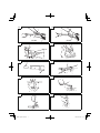 2
2
-
 3
3
-
 4
4
-
 5
5
-
 6
6
-
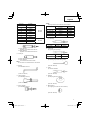 7
7
-
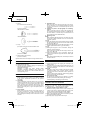 8
8
-
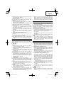 9
9
-
 10
10
-
 11
11
-
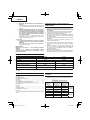 12
12
-
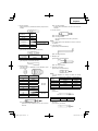 13
13
-
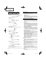 14
14
-
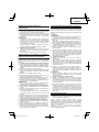 15
15
-
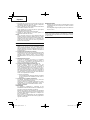 16
16
-
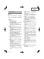 17
17
-
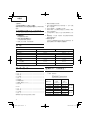 18
18
-
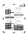 19
19
-
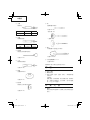 20
20
-
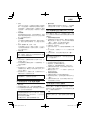 21
21
-
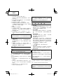 22
22
-
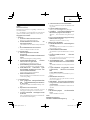 23
23
-
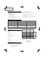 24
24
-
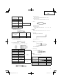 25
25
-
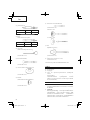 26
26
-
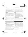 27
27
-
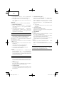 28
28
-
 29
29
-
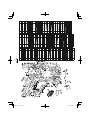 30
30
-
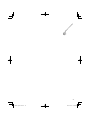 31
31
-
 32
32


Hitachi PR-25B Instrucciones de operación
- Categoría
- Martillos perforadores
- Tipo
- Instrucciones de operación
- Este manual también es adecuado para
en otros idiomas
Artículos relacionados
-
Hikoki DH 40SA Manual de usuario
-
Hitachi dh 38ss Handling Instructions Manual
-
-
-
-
Hitachi Koki dh 38ss El manual del propietario
-
-
-
-
Hitachi Koki DH24PB3 Manual de usuario