
Rotary Hammer
Martillo perforador
햄어드릴
สวานเจาะกระแทกโรตารี่
DH 40SR
Handling instructions
Instrucciones de manejo
취급 설명서
คูมือการใชงาน
Read through carefully and understand these instructions before use.
Leer cuidadosamente y comprender estas instrucciones antes del uso.
본 설명서를 자세히 읽고 내용을 숙지한 뒤 제품을 사용하십시오.
โปรดอานโดยละเอียดและทําความเขาใจกอนใชงาน

1
321
2
1
5
6
3
7
654
987
0
A
B
121110
C
D
E
F
G
1
3
45
6
8
9
4
7
A
00Table_DH40SR_CKTp0102.p65 12.7.27, 14:111

2
13 14 15
E
H
I
J
K
16 17 18
I
N
J
M
L
K
J
19 20
73
17 mm
7 mm
O
P
O
00Table_DH40SR_CKTp0102.p65 12.7.27, 14:112

3
English Español
1
Tool shank Barrena
2
Grease
Grasa
3
Retainer (tool holder) Retén (soporte de herramienta)
4
Retainer edge Borde del retén
5
Push button Botón pulsador
6
Front cover Cubierta delantera
7
Outlet Salida
8
Stopper Tope
9
Side handle Mango lateral
0
Plug Tapón
!
Snap off this portion after driving in
the self-drilling anchor.
Sacar esta parte luego de colocar
el anclaje de autoperforación.
@
Hole depth Prof. del orifi cio
#
Drift key Cuña sacabarrena
$
Wrench out Extraer
%
Taper shank adapter Adaptador de barrena ahusada
^
Drill bit (taper shank)
Broca de barrena (barrena
ahusada)
&
Indicating groove shows standard
depth matching the out-side
diameter of the anchor for drilling.
Ranura indicadora que muestra
la profundidad normal de
coincidencia del diámetro exterior
del anclaje para taladrar.
*
Cotter Chaveta
(
Rest Apoyo
)
Core bit Barrena tubular
q
Core bit shank Espiga de barrena
w
Guide plate Placa guía
e
Center pin Pasador central
r
Core bit tip Punta barrena tubular
t
Crank cover Cubierta de la cubierta del cigüeñal
y
Wear limit Límite de desgaste
u
No. of carbon brush N° de escobilla de carbón

4
한국어
1
툴 섕크
2
그리스
3
리테이너(공구 홀더)
()
4
리테이너 엣지
5
푸시 버튼
6
전면 커버
7
배출구
8
스토퍼
9
사이드 핸들
0
플러그
!
자체 드릴 앵커를 밀어 넣은 후 이
부분을 툭 부러뜨리십시오.
@
구멍 깊이
#
드리프트 키
$
렌치 아웃
%
테이퍼 생크 어댑터
^
드릴 비트(테이퍼 생크)
()
&
표시 홈은 드릴용 앵커의 외경과
일치하는 표준 깊이를 표시합니다.
*
쐐기
(
받침대
)
코어 비트
q
코어 비트 생크
w
가이드 플레이트
e
센터 핀
r
코어 비트 팁
t
크랭크 커버
y
마모 한도
u
카본 브러시 번호

5
English
GENERAL SAFETY RULES
WARNING!
Read all instructions
Failure to follow all instructions listed below may result in
electric shock, fire and/or serious injury.
The term “power tool” in all of the warnings listed below
refers to your mains operated (corded) power tool or battery
operated (cordless) power tool.
SAVE THESE INSTRUCTIONS
1) Work area
a) Keep work area clean and well lit.
Cluttered and dark areas invite accidents.
b) Do not operate power tools in explosive
atmospheres, such as in the presence of flammable
liquids, gases or dust.
Power tools create sparks which may ignite the dust
of fumes.
c) Keep children and bystanders away while operating
a power tool.
Distractions can cause you to lose control.
2) Electrical safety
a) Power tool plugs must match the outlet.
Never modify the plug in any way.
Do not use any adapter plugs with earthed
(grounded) power tools.
Unmodified plugs and matching outlets will reduce
risk of electric shock.
b) Avoid body contact with earthed or grounded
surfaces such as pipes, radiators, ranges and
refrigerators.
There is an increased risk of electric shock if your
body is earthed or grounded.
c) Do not expose power tools to rain or wet conditions.
Water entering a power tool will increase the risk of
electric shock.
d) Do not abuse the cord. Never use the cord for
carrying, pulling or unplugging the power tool.
Keep cord away from heat, oil, sharp edges or
moving parts.
Damaged or entangled cords increase the risk of
electric shock.
e) When operating a power tool outdoors, use an
extension cord suitable for outdoor use.
Use of a cord suitable for outdoor use reduces the
risk of electric shock.
3) Personal safety
a) Stay alert, watch what you are doing and use
common sense when operating a power tool.
Do not use a power tool while you are tired or
under the influence of drugs, alcohol or medication.
A moment of inattention while operating power tools
may result in serious personal injury.
b) Use safety equipment. Always wear eye protection.
Safety equipment such as dust mask, non-skid safety
shoes, hard hat, or hearing protection used for
appropriate conditions will reduce personal injuries.
c) Avoid accidental starting. Ensure the switch is in
the off position before plugging in.
Carrying power tools with your finger on the switch
or plugging in power tools that have the switch on
invites accidents.
d) Remove any adjusting key or wrench before turning
the power tool on.
A wrench or a key left attached to a rotating part of
the power tool may result in personal injury.
e) Do not overreach. Keep proper footing and balance
at all times.
This enables better control of the power tool in
unexpected situations.
f) Dress properly. Do not wear loose clothing or
jewellery. Keep your hair, clothing and gloves away
from moving parts.
Loose clothes, jewellery or long hair can be caught
in moving parts.
g) If devices are provided for the connection of dust
extraction and collection facilities, ensure these are
connected and properly used.
Use of these devices can reduce dust related hazards.
4) Power tool use and care
a) Do not force the power tool. Use the correct power
tool for your application.
The correct power tool will do the job better and
safer at the rate for which it was designed.
b) Do not use the power tool if the switch does not
turn it on and off.
Any power tool that cannot be controlled with the
switch is dangerous and must be repaired.
c) Disconnect the plug from the power source before
making any adjustments, changing accessories, or
storing power tools.
Such preventive safety measures reduce the risk of
starting the power tool accidentally.
d) Store idle power tools out of the reach of children
and do not allow persons unfamiliar with the power
tool or these instructions to operate the power
tool.
Power tools are dangerous in the hands of untrained
users.
e) Maintain power tools. Check for misalignment or
binding of moving parts, breakage of parts and any
other condition that may affect the power tools
operation.
If damaged, have the power tool repaired before
use.
Many accidents are caused by poorly maintained
power tools.
f) Keep cutting tools sharp and clean.
Properly maintained cutting tools with sharp cutting
edges are less likely to bind and are easier to control.
g) Use the power tool, accessories and tool bits etc.,
in accordance with these instructions and in the
manner intended for the particular type of power
tool, taking into account the working conditions
and the work to be performed.
Use of the power tool for operations different from
intended could result in a hazardous situation.
5) Service
a) Have your power tool serviced by a qualified repair
person using only identical replacement parts.
This will ensure that the safety of the power tool is
maintained.
PRECAUTION
Keep children and infirm persons away.
When not in use, tools should be stored out of reach of
children and infirm persons.
01Eng_DH40SR_CKT 7/31/12, 3:13 PM5

English
6
䡬 Large dia. hole boring (Rotation + Hammering)
(1) Center pin
䢇 Applied to core bits from 38 mm to 105 mm
䢇 Applied to core bits 32 mm and 35 mm
NOTE
Do not use core bits 25 mm or 29 mm.
(2) Core bit
䢇 External dia. 25, 29, 32, 35, 38, 45, 54, 64, 79, 94,
105 mm
(with guide plate, not applicable to cores 25 mm or
29 mm)
(3) Core bit shank
䢇 Applied to core bits above 38 mm
䢇 Applied to core bits below 35 mm
䡬 Anchor work (for self-anchors)
STANDARD ACCESSORIES
(1) Case (Molded plastic) ................................................. 1
(2) Side Handle ................................................................. 1
(3) Stopper ........................................................................ 1
(4) Hammer Grease A ...................................................... 1
Standard accessories are subject to change without
notice.
OPTIONAL ACCESSORIES (sold separately)
䡬 Through-hole drilling (Rotation + Hammering)
(1) Drill bit (hexagon shank)
Overall length: 280, 400, 505 mm
External dia.: 16, 19, 22, 25, 28, 32, 38 mm
䡬 Anchor hole drilling (Rotation + Hammering)
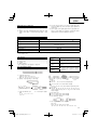
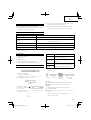
SPECIFICATIONS
*
1
Be sure to check the nameplate on product as it is subject to change by areas.
*
2
With constant velocity regulator.
Voltage (by areas)*
1
(110 V, 115 V, 120 V, 127 V, 220 V, 230 V, 240 V)
Power input 950 W*
1
Capacity Drill bit: 40 mm
Core bit: 120 mm
No load speed*
2
510 /min
Full-load impact rate*
2
2800 /min
Weight (without cord, side handle) 6.5 kg
(1) Drill bit (taper shank)
External dia.: 11, 12, 14.3,
14.5, 17.5,
21.5 mm
(2) Taper shank
adapter
(3) Cotter
PRECAUTIONS ON USING ROTARY HAMMER
䡬 Wear earplugs to protect your ears during operation.
䡬 Do not touch the bit during or immediately after
operation. The bit becomes very hot during
operation and could cause serious burns.
䡬 Before starting to break, chip or drill into a wall,
floor or ceiling, thoroughly confirm that such items
as electric cables or conduits are not buried inside.
䡬 Always hold the body handle and side handle of
the power tool firmly. Otherwise the counterforce
produced may result in inaccurate and even
dangerous operation.
(2) Core
bit
(3) Core bit
shank
(Guide
plate)
Taper shank
adapter
Morse taper
(No. 1)
Morse taper
(No. 2)
A-taper
B-taper
Application drill bit
Drill bit (taper shank)
11, 12, 14.3, 14.5, 17.5 mm
Drill bit (tape shank)
21.5 mm
Taper shank adapter formed A-
taper or B-taper is provided as
optional accessory, but drill bit for
it is not provided.
(1) Center
pin
01Eng_DH40SR_CKT 7/31/12, 3:13 PM6

7
English
(1) Anchor adapter (for Rotation + Hammering)
Anchor size:
W1/4, W5/16, W3/8, W1/2, W5/8
(No. 20) (No. 25) (No. 30) (No. 40) (No. 50)
䡬 Cursing (Hammering)
䡬 Groove digging and edging (Hammering)
䡬 Asphalt cutting (Hammering)
䡬 Syringe (for chip removal)
䡬 Hammer grease A
500 g (in a can)
70 g (in a green tube)
30 g (in a green tube)
Optional accessories are subject to change without
notice.
APPLICATIONS
䡬 Drilling holes in concrete
䡬 Drilling anchor holes
䡬 Crushing concrete, chipping, digging, and squaring
(by applying optional accessories)
PRIOR TO OPERATION
1. Power source
Ensure that the power source to be utilized conforms
to the power requirements specified on the product
nameplate.
2. Power switch
Ensure that the power switch is in the OFF position. If
the plug is connected to a power receptacle while the
power switch is in the ON position, the power tool
will start operating immediately, which could cause a
serious accident.
3. Extension cord
When the work area is removed from the power
source, use an extension cord of sufficient thickness
and rated capacity. The extension cord should be
kept as short as practicable.
4. How to install tool
NOTE
For tools such as a bull point and a cold chisel, use
only Hitachi genuine parts.
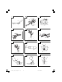
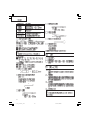
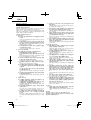
(1) Clean, then smear the tool shank with the grease
provided in the green tube. (Fig. 1)
(2) Press the push button, slightly lift the tool retainer in
the direction of arrow
A
as shown in Fig. 2 to hook
the tool retainer edge with the push button and
engage the push button.
(3) Release your finger from the push button and further
lift the tool retainer in the direction of arrow
A
.
NOTE
First time when the tool retainer is lifted, remove your
finger from the push button. If the push button is kept
pressed, the edge of the tool retainer comes in contact
with your finger and the tool retainer cannot be lifted.
(4) Fully insert the tool shank into the hexagonal hole in
the front cover.
(5) Return the tool retainer to secure the tool.
(6) Pull the tool to make sure it is locked completely.
NOTE
Remove in the reverse order of installation.
WHEN THE PUSH BUTTON DOES NOT
OPERATE SMOOTHLY
When the push button does not operate smoothly, please
remove dirt from the inside through the outlet using a
wire, etc. Then lubricate lubricating oil and push the
push button several times to make it operate smoothly.
(Fig. 3)
HOW TO USE THE ROTARY HAMMER
1. How to drill holes (Fig. 4)
(1) Pull the switch trigger after applying the drill bit tip to
the drilling position.
(2) It is unnecessary to forcibly press the rotary hammer
main body. It is sufficient to slightly press the rotary
hammer to an extent that shavings are freely
discharged.
CAUTION
Although this machine is equipped with a safety
clutch, if the drill bit becomes bound in concrete or
other material, the resultant stoppage of the drill bit
could cause the machine body to turn in reaction.
Ensure that the main handle and side handle are
gripped firmly during operation.
2. How to chisel or demolish (Fig. 5)
By applying the drill bit tip to the chiseling or
demolishing position, operate the rotary hammer by
utilizing its empty weight.
Forcible pressing or thrusting is unnecessary.
3. Install the stopper (Fig. 6)
(1) Loosen the side handle and insert the straight portion
of the stopper into the handle bolt hole.
(2) Move the stopper to the specified position and rotate
the grip of the side handle clockwise to fix the stopper.
4. Warming up (Fig. 7)
The grease lubrication system in this unit may require
warming up in cold regions.
Position the end of the bit so makes contact with the
concrete, turn on the switch and perform the warming
up operation. Make sure that a hitting sound is
produced and then use the unit.
(2) Drift key
(1) Bull point
Overall length: 280, 450 mm
(1) Cold chisel
Overall length: 280, 450 mm
(1) Cutter
01Eng_DH40SR_CKT 7/31/12, 3:13 PM7

English
8
CAUTION
When the warming up operation is performed, hold
the side handle and the main body securely with
both hands to maintain a secure grip and be careful
not to twist your body by the jammed drill bit.
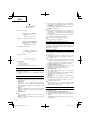
DRILLING AND DRIVING-IN OPERATIONS FOR
ANCHORS
Use the optional accessories for anchors, such as anchor
adapter and taper shank adapter.
1. When a rotation hammering anchor adapter is used.
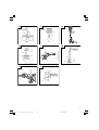
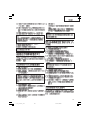
(1) Install the self-drilling anchor in the anchor adapter.
(Fig. 8)
(2) Turn ON the switch and drill a base hole with the self-
drilling anchor. (Fig. 9)
At the start of the hole-drilling slightly tilt the rotary
hammer to determine the hole position.
(3) After cleaning out dust with a syringe, attach the
plug to the anchor tip and drive in the anchor with a
manual hammer.
(4) After driving in the anchor, use the drift key to separate
the anchor. (Fig. 10)
(5) By employing a manual hammer or pliers, snap off
the tapered portion of the anchor. (Fig. 11)
CAUTION
Since the snapped-off tapered portion will fly about,
pay attention to the snapping direction.
2. When a taper shank adapter is used (Fig. 12)
(1) Install drill bit with taper shank in the taper shank
adapter.
(2) Turn the power on and drill a base hole to the depth
sounded by indicating groove on the drill bit.
(3) After cleaning out dust with a syringe, attach the plug
to the anchor tip and drive in the anchor with a
manual hammer.
(4) To remove the drill bit (taper shank), insert the cotter
into the slot of the taper shank adapter and strike the
head of the cotter with a manual hammer supporting
on a rest. (Fig. 13)
HOW TO HANDLE A CORE BIT
When a core bit is used, large diameter holes and blind
holes can be drilled. In this case, use optional accessories
for core bits (such as a center pin and core bit shank) for
more efficient operation.
1. Mounting
CAUTION
Prior to mounting a core bit, always disconnect the
plug from the power supply receptacle.
(1) Mount the core bit on the core bit shank. (Fig. 14)
Before that, feed oil to the screw portion of core bit
shank for easy dismounting.
(2) Mount the core bit shank on the main body in the
same manner as in mounting the drill bit and the bull
point. (Fig. 15)
(3) Insert the center pin into the guide plate until it reaches
the extremity.
(4) Fit in the guide plate by aligning its concaved portion
with the core bit tip. When the position of the concave
is shifted by turning the guide plate right or left, the
guide plate never slips off even when the drill is used
in a downward direction. (Fig. 16)
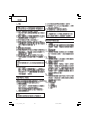
2. Drilling holes
(1) Insert the plug into a receptacle.
(2) A spring is built in the center pin. By straightly and
gently pressing it to the wall or floor surface, the
entire surface of the core bit tip attains contact to
start the hole drilling job. (Fig. 17)
(3) When the hole depth reaches approximately 5 mm,
the hole position can be determined. Then remove
the center pin and guide plate from the core bit and
continue the hole drilling job.
CAUTION
When removing the center pin and guide plate, always
disconnect the plug from the receptacle.
3. How to dismount the core bit
Remove the core bit shank from the rotary hammer,
hold the core bit with one hand, and strongly strike
the head of the hexagonal shank portion of the core
bit shank with a manual hammer two or three times,
whereby the round head screw is loosened and the
rotary hammer is ready for disassembly. (Fig. 18)
HOW TO REPLACE GREASE
This machine is of full air-tight construction to protect
against dust and to prevent lubricant leakage. Therefore,
the machine can be used without lubrication for long
periods. Replace the grease as described below.
1. Grease replacement period
After purchase, replace grease after every 6 months
of usage. Ask for grease replacement at the nearest
Hitachi authorized Service center. Proceed for
replacement of grease.
2. Grease replenishment
CAUTION
Before replenishing the grease, turn the power off
and pull out the power plug.
(1) Remove the crank cover and wipe off the grease
inside. (Fig. 19)
(2) Supply 30g of Hitachi Electric Hammer Grease A
(Standard accessory, contained in tube) to the crank
case.
(3) After replenishing the grease, install the crank cover
securely.
NOTE
The Hitachi Electric Hammer Grease A is of the low
viscosity type. If necessary purchase from an Hitachi
authorized Service center.
MAINTENANCE AND INSPECTION
1. Inspecting the tool
Since use of a dull tool will degrade efficiency and
cause possible motor malfunction, sharpen or replace
the tool as soon as abrasion is noted.
2. Inspecting the mounting screws
Regularly inspect all mounting screws and ensure
that they are properly tightened. Should any of the
screws be loose, retighten them immediately. Failure
to do so could result in serious hazard.
3. Maintenance of the motor
The motor unit winding is the very “heart” of the
power tool. Exercise due care to ensure the winding
does not become damaged and/or wet with oil or
water.
01Eng_DH40SR_CKT 7/31/12, 3:13 PM8

9
English
4. Inspecting the carbon brushes (Fig. 20)
The Motor employs carbon brushes which are
consumable parts. When they become worn to or
near the “wear limit”, it could result in motor trouble.
When an auto-stop carbon brush is equipped, the
motor will stop automatically. At that time, replace
both carbon brushes with new ones which have the
same carbon brush Numbers shown in the figure. In
addition, always keep carbon brushes clean and
ensure that they slide freely within the brush holders.
5. Replacing carbon brushes
Loosen the two set screws and remove the tail cover.
Remove the brush caps and carbon brushes. After
replacing the carbon brushes, tighten the brush caps
securely and install the tail cover with securely
tightening two set screws.
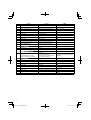
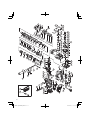
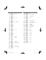
6. Service parts list
A: Item No.
B: Code No.
C: No. Used
D: Remarks
CAUTION
Repair, modification and inspection of Hitachi Power
Tools must be carried out by an Hitachi Authorized
Service Center.
This Parts List will be helpful if presented with the
tool to the Hitachi Authorized Service Center when
requesting repair or other maintenance.
In the operation and maintenance of power tools, the
safety regulations and standards prescribed in each
country must be observed.
MODIFICATIONS
Hitachi Power Tools are constantly being improved
and modified to incorporate the latest technological
advancements.
Accordingly, some parts (i.e. code numbers and/or
design) may be changed without prior notice.
NOTE
Due HITACHI’s continuing program of research and
development, the specifications herein are subject to
change without prior notice.
01Eng_DH40SR_CKT 7/31/12, 3:13 PM9

Español
10
PRECAUCION ES GENERAL ES PARA
OPERACIÓN
¡ADVERTENCIA!
Lea todas las instrucciones
Si no se siguen las instrucciones de abajo podría producirse
una descarga eléctrica, un incendio y/o daños graves.
El término “herramienta eléctrica” en todas las
advertencias indicadas a continuación hace referencia a
la herramienta eléctrica que funciona con la red de
suministro (con cable) o a la herramienta eléctrica que
funciona con pilas (sin cable).
CONSERVE ESTAS INSTRUCCIONES
1) Área de trabajo
a) Mantenga la zona de trabajo limpia y bien
iluminada.
Las zonas desordenadas y oscuras pueden
provocar accidentes.
b) No utilice las herramientas eléctricas en entornos
explosivos como, por ejemplo, en presencia de
líquidos inflamables, gases o polvo.
Las herramientas eléctricas crean chispas que
pueden hacer que el polvo desprenda humo.
c) Mantenga a los niños y transeúntes alejados
cuando utilice una herramienta eléctrica.
Las distracciones pueden hacer que pierda el control.
2) Seguridad eléctrica
a) Los enchufes de las herramientas eléctricas tienen
que ser adecuados a la toma de corriente.
No modifique el enchufe.
No utilice enchufes adaptadores con herramientas
eléctricas conectadas a tierra.
Si no se modifican los enchufes y se utilizan tomas
de corriente adecuadas se reducirá el riesgo de
descarga eléctrica.
b) Evite el contacto corporal con superficies conectadas
a tierra como tuberías, radiadores y frigoríficos.
Hay mayor riesgo de descarga eléctrica si su
cuerpo está en contacto con el suelo.
c) No exponga las herramientas eléctricas a la lluvia
o a la humedad.
La entrada de agua en una herramienta eléctrica
aumentará el riesgo de descarga eléctrica.
d) No utilice el cable incorrectamente. No utilice el
cable para transportar, tirar de la herramienta
eléctrica o desenchufarla.
Mantenga el cable alejado del calor, del aceite, de
bordes afilados o piezas móviles.
Los cables dañados o enredados aumentan el
riesgo de descarga eléctrica.
e) Cuando utilice una herramienta eléctrica al aire
libre, utilice un cable prolongador adecuado para
utilizarse al aire libre.
La utilización de un cable adecuado para usarse
al aire libre reduce el riesgo de descarga eléctrica.
3) Seguridad personal
a) Esté atento, preste atención a lo que hace y utilice
el sentido común cuando utilice una herramienta
eléctrica.
No utilice una herramienta eléctrica cuando esté
cansado o esté bajo la influencia de drogas,
alcohol o medicación.
La distracción momentánea cuando utiliza
herramientas eléctricas puede dar lugar a
importantes daños personales.
b) Utilice equipo de seguridad. Utilice siempre una
protección ocular.
El equipo de seguridad como máscara para el
polvo, zapatos de seguridad antideslizantes, casco
o protección para oídos utilizado para condiciones
adecuadas reducirá los daños personales.
c) Evite un inicio accidental. Asegúrese de que el
interruptor está en “off” antes de enchufarlo.
El transporte de herramientas eléctricas con el
dedo en el interruptor o el enchufe de
herramientas eléctricas con el interruptor
encendido puede provocar accidentes.
d) Retire las llaves de ajuste antes de encender la
herramienta eléctrica.
Si se deja una llave en una pieza giratoria de la
herramienta eléctrica podrían producirse daños
personales.
e) No se extralimite. Mantenga un equilibrio
adecuado en todo momento.
Esto permite un mayor control de la herramienta
eléctrica en situaciones inesperadas.
f) Vístase adecuadamente. No lleve prendas sueltas
o joyas. Mantenga el pelo, la ropa y los guantes
alejados de las piezas móviles.
La ropa suelta, las joyas y el pelo largo pueden
pillarse en las piezas móviles.
g) Si se proporcionan dispositivos para la conexión
de extracción de polvo e instalaciones de recogida,
asegúrese de que están conectados y se utilizan
adecuadamente.
La utilización de estos dispositivos puede reducir
los riesgos relacionados con el polvo.
4) Utilización y mantenimiento de las herramientas
eléctricas
a) No fuerce la herramienta eléctrica. Utilice la
herramienta eléctrica correcta para su aplicación.
La herramienta eléctrica correcta trabajará mejor
y de forma más segura si se utiliza a la velocidad
para la que fue diseñada.
b) No utilice la herramienta eléctrica si el interruptor
no la enciende y apaga.
Las herramientas eléctricas que no pueden
controlarse con el interruptor son peligrosas y
deben repararse.
c) Desconecte el enchufe de la fuente eléctrica antes
de hacer ajustes, cambiar accesorios o almacenar
herramientas eléctricas.
Estas medidas de seguridad preventivas reducen
el riesgo de que la herramienta eléctrica se ponga
en marcha accidentalmente.
d) Guarde las herramientas eléctricas que no se
utilicen para que no las cojan los niños y no
permita que utilicen las herramientas eléctricas
personas no familiarizadas con las mismas o con
estas instrucciones.
Las herramientas eléctricas son peligrosas si son
utilizadas por usuarios sin formación.
e) Mantenimiento de las herramientas eléctricas.
Compruebe si las piezas móviles están mal
alineadas o unidas, si hay alguna pieza rota u
otra condición que pudiera afectar al
funcionamiento de las herramientas eléctricas.
Si la herramienta eléctrica está dañada, llévela a
reparar antes de utilizarla.
02Spa_DH40SR_CKT 7/31/12, 2:52 PM10

Español
11
Se producen muchos accidentes por no realizar
un mantenimiento correcto de las herramientas
eléctricas.
f) Mantenga las herramientas de corte afiladas y
limpias.
Las herramientas de corte correctamente
mantenidas con los bordes de corte afilados son
más fáciles de controlar.
g) Utilice la herramienta eléctrica, los accesorios y
las brocas de la herramienta, etc., de acuerdo con
estas instrucciones y de la manera adecuada para
el tipo de herramienta eléctrica, teniendo en
cuenta las condiciones laborales y el trabajo que
se va a realizar.
La utilización de la herramienta eléctrica para
operaciones diferentes a pretendidas podría dar
lugar a una situación peligrosa.
5) Revisión
a) Lleve su herramienta a que la revise un experto
cualificado que utilice sólo piezas de repuesto
idénticas.
Esto garantizará el mantenimiento de la seguridad
de la herramienta eléctrica.
PRECAUCIÓN
Mantenga a los niños y a las personas enfermas alejadas.
Cuando no se utilicen, las herramientas deben
almacenarse fuera del alcance de los niños y de las
personas enfermas.
PRECAUCIONES AL USAR EL MARTILLO
PERFORADOR
䡬 Usar protectores de oídos durante el trabajo.
䡬 No tocar la broca durante ni inmdiatamente después
de trabajar, puesto que se pone ardiente y puede
causar quemaduras serias.
䡬 Antes de empezar a romper, picar o perforar en una
pared, suelo o techo, comprobar cuidadosamente
que no hayan objetos empotrados, tales como cables
o conductos eléctricos.
䡬 Sujetar siempre firmemente al asidero del cuerpo y
el asidero lateral de la harrmienta. De lo contrario, la
contrafuerza producida podría causar un
funcionamiento impreciso e incluso peligroso.
ACCESORIOS ESTANDAR
(1) Caja (Plástica) ............................................................ 1
(2) Mango lateral ............................................................. 1
(3) Tope ............................................................................ 1
(4) Grasa A para martillo ................................................ 1
Los accesorios estándar están sujetos a cambios sin
previo aviso.
ACCESORIOS FACULTATIVOS
(de venta por separado)
䡬 Perforación por orificio (Rotación + Martilleo)
(1) Barrena (espiga hexagonal)
Longitud total: 280 400 505 mm
Diámetro externo: 16 19 22 25 28 32 38 mm
Voltaje (por áreas)*
1
(110 V, 115 V, 120 V, 127 V, 220 V, 230 V, 240 V)
Entrada 950 W*
1
Capacidad Barrena: 40 mm
Barrena tubular: 120 mm
Velocidad sin carga*
2
510 /min
Impacto a carga plena*
2
2800 /min
Peso (sin cable ni mango lateral) 6,5 kg
ESPECIFICACIONES
*
1
Verficar indefectiblemente los datos de la placa de características de la máquina, pues varían de acuerdo al país de
destino.
*
2
Con regulador de velocidad constante
䡬 Perforación de orificio de anclaje (Rotación + Martilleo)
(3) Cortadora
(2) Adaptador
de espiga
cónica
(1) Barrena
Diàmetro externo:
11 12 14,3 14,5 17,5
21,5 mm
Adaptador de
espiga cónica
Cono Morse
(N°. 1)
Cono Morse
(N°. 2)
Cono A
Cono B
Barrena aplicable
Barrena (espiga cónica)
11 12 14,3 14,5 17,5 mm
Barrena (espiga cónica)
21,5 mm
Adaptador de espiga cónica
formada por el dispositivo
ahusador A o el B, provisto como
accesorio opcional, pero no se
provee barrena de perforar.
02Spa_DH40SR_CKT 8/1/12, 10:00 AM11

Español
12
䡬 Perforación de orificio de diámetro grande (Rotación
+ Martilleo)
(1) Pasador central
䢇 Aplicable a barrenas de 38 mm – 105 mm
䢇 Aplicable a barrenas de 32 mm y 35 mm
NOTA
No usar barrenas de 25 y 29 mm
(2) Barrena
䢇 Diámetro externo
25 29 32 35 38 45 54 64 79 94 105 mm
(Con placa guía no aplicable a barrenas de 25 y 29
mm)
(3) Espiga de barrena tubular
䢇 Aplicable a barrenas de más de 38 mm
䢇 Aplicable a barrenas de menos de 35 mm
䡬 Trabajo de anclaje (para anclajes de perforado propio)
(1) Adaptador de anclaje (para rotación + Martilleo)
Tamaño de anclaje:
W1/4, W5/16, W3/8, W1/2, W5/8
(N°. 20) (N°. 25) (N°. 30) (N°. 40) (N°. 50)
䡬 Romper (Martilleo)
䡬 Excavar, ranurado y rebordes (Martilleo)
䡬 Corte de asfalto (Martilleo)
䡬 Jeringa (extracción de resíduos)
䡬 Grasa A para martillo
500 g (en una lata)
70 g (en un tubo naranja)
30 g (en un tubo naranja)
Los accesorios facultativos están sujetos a cambios sin
previo aviso.
APLICACIONES
䡬 Perforación de orificios en concreto
䡬 Perforación de orificios de anclaje
䡬 Romper hormigón, picar, cavar y cuartear (con
accesorios opcionales).
ANTES DE LA PUESTA EN MARCHA
1. Alimentación
Asegurarse de que la alimentación de red que ha de
ser utilizada responda a las exigencias de corriente
especificadas en la placa de características del
producto.
2. Conmutador de alimentación
Asegurarse de que el conmutador de alimentación
esté en la posición OFF (desconectado). Si la clavija
está conectada en la caja del enchufe mientras el
conmutador de alimentación esté en posición ON
(conectado) las herramientas eléctricas empezarán a
trabajar inmediatamente, provocando un serio
accidente.
3. Cable de prolongación
Cuando está alejada el área de trabajo de la red de
alimentación, usar un cable de prolongación de un
grosor y potencia normal suficiente. El cable de
prolongación debe ser mantenido lo más corto
posible.
4. Montaje de la herramienta
NOTA
Para usar herramientas tales como el puntero y
cortafrío, usar siempre piezas genuinas Hitachi.
(1) Limpiar y engrasar la espiga con la grasa provista.
(Fig. 1)
(2) Presione el botón pulsador, levante ligeramente el
retén de herramienta en el sentido de la flecha
A
como se muestra en la Fig. 2 para enganchar el borde
del retén de herramienta en el botón pulsador y dejar
enganchado dicho botón.
(3) Suelte el dedo del botón pulsador y levante más el
retén de herramienta en el sentido de la flecha
A
.
NOTA
Cuando levante por primera vez el retén de herramienta,
quite el dedo del botón pulsador. Si mantuviese
presionado el botón pulsador, el borde del retén de
herramienta entraría en contacto con su dedo y no podría
levantar el retén de herramienta.
(4) Inserte completamente el vástago de la herramienta
en el orificio hexagonal de la cubierta frontal.
(5) Devuelva el retén de herramienta para asegurar la
herramienta.
(6) Tire de la herramienta para asegurarse de que se
encuentran completamente bloqueado.
NOTA
Quitar la herramienta invirtiendo el orden de instalación.
CUANDO EL BOTÓN PULSADOR NO FUNCIONE
SUAVEMENTE
Cuando el botón pulsador no funcione suavemente,
elimine las suciedad del interior a través de la salida con
un alambre, etc. Después aplique aceite lubricante y
presione varias veces el botón pulsador para hacer que
funcione suavemente. (Fig. 3)
(1) Puntero
Largo total: 280 450 mm
(1) Cortafrio
Largo total: 280 450 mm
(1) Cortadora
(2) Cuña sacabarrenas
(1) Pasador
contral
(Placa
guía)
(2) Barrena (3) Espiga de
barrena tubular
02Spa_DH40SR_CKT 7/31/12, 2:52 PM12

Español
13
MODO DE UTILIZACION
1. Taladrar orificios (Fig. 4)
(1) Oprimir el interruptor de operación luego de apoyar
la punta de la barrena en la posición de taladrar.
(2) No es necesario presionar el cuerpo principal del
martillo perforador. Es suficiente con empujar
ligeramente el martillo de taladrar teniendo en cuenta
que los materiales saltan libremente, al taladrar.
PRECAUCION
Aunque este aparato se equipa con un embrague de
seguridad, si se atasca la barrena de taladrar en el
hormigón u otro material semejante, puede pasar
que, al atascarse la barrena, el cuerpo del martillo
gire en dirección opuesta.
Asegurarse entonces de que el mango principal y el
lateral están bien empuñados durante el uso de esta
herramienta.
2. Forma de picar o demoler (Fig. 5)
Aplicando la punta de la barrena en posición de picar
o demoler, hacer funcionar el martillo perforador
aplicando su propio peso.
No es necesario presionar o empujar excesivamente.
3. Instalar el tope (Fig. 6)
(1) Alfojar el mango lateral e insertar la parte recta del
tope en el orificio del perno de manija.
(2) Aflojar el mango lateral, y mover el tope a la posición
especificada y rotar la empuñadura del mango lateral
a la derecha para fijar el tope.
4. Calentamiento (Fig. 7)
El sistema de lubricación de esta unidad puede
requerir calentamiento en ciertas regiones.
Coloque el extremo de la broca de forma que entre
en contacto con el hormigón, ponga en ON el
interruptor de alimentación principal de la unidad, y
realice la operación de calentamiento. Cerciórese de
que se produzca un sonido de martilleo, y después
utilice la unidad.
PRECAUCION
Cuando haya realizado la operación de calentamiento,
sujete con seguridad el mango lateral y el cuerpo
principal con ambas manos para asegurar una buena
sujeción y tenga cuidado de no torcer su cuerpo
mediante una broca atascada.
PERFORACION E INCRUSTACION DE
ANCLAJES
Usar los accesorios opcionales para los anclajes, tales
como adaptador de anclaje y adaptador de espiga cónica.
1. Cuando se utiliza un adaptador de anclaje para
martilleo rotativo.
(1) Instalar el anclaje de perforación propia en el
adaptador de anclaje. (Fig. 8)
(2) Poner el interruptor en “ON” y perforar un agujero
base con el anclaje de auto-perforación. (Fig. 9)
Al comenzar a perforar el orificio, incline ligeramente
el martillo rotativo para determinar la posición del
orificio.
(3) Después de limpiar el polvo con una jeringa, colocar
el tapón en la punta del anclaje y meterlo con un
martillo manual.
(4) Luego de insertar el anclaje, usar la cuña sacabarrenas
para separar el anclaje. (Fig. 10)
(5) Empleando un martillo manual sacar de un glope la
parte cónica del anclaje. (Fig. 11)
PRECAUCION
Debido a que esta parte sobrante saltará al golpearla,
prestar atención a su dirección.
2. Cuando se use un adaptador de espiga cónica
(Fig. 12)
(1) Instalar la barrena en el adaptador de espiga cónica.
(2) Conectar el aparato y perforar un orificio base a una
profundidad correspondiente a la ranura indicadora
del tope en el orificio del perno de manija por la de la
barrena.
(3) Luego, limpiar el polvo con una jeringa, colocar el
tapón en la punta del anclaje e instertar éste con un
martillo manual.
(4) Para quitar la broca (espiga ahusada), insertar la
chaveta en la ranura del adaptador de la espiga
ahusada y golperar la cabeza de la chaveta con un
martillo. Usar apoyos como se muestra en la
Fig. 13.
USO DE BARRENA TUBULAR
Cuando se usa una barrena tubular, pueden perforarse
orificios grandes y orificios ciegos. En este caso, hay que
emplear los accesorios opcionales para barrenas
tubulares (tales como el pasador central y la espiga de
barrena tubular) para trabajar de modo más racional.
1. Montaje
PRECAUCION
Antes de montar una barrena tubular, siempre hay
que desenchufar el aparato del tomacorriente de la
pared.
(1) Colocar la barrena tubular en la espiga
correspondiente (Fig. 14).
Antes de ello, agregar aceite en la parte de rosca de
la barrena tubular para facilitar el desmontaje.
(2) Colocar la barrena tubular en el cuerpo principal del
taladro del mismo modo que se hizo con la barrena y
el puntero (Fig. 15)
(3) Insertar el pasador central en la placa guía gasta que
alcance la extremidad.
(4) Colocar la placa quía alineando su parte cóncava con
la punta de la barrena tubular. Cuando la posición de
la parte cóncava se cambia, girando la placa guía a
derecha o izquierda, ésta nunca debe salirse, aún
cuando el taladro se use en dirección hacia abajo
(Fig. 16).
2. Perforación
(1) Enchufar el aparato en el tomacorriente de pared.
(2) El pasador central tiene un resorte incluido y,
presionándolo levemente y en forma recta, se pone
en contacto toda la superficie de la punta de la barrena
para comenzar a taladrar. (Fig. 17)
(3) Cuando el orificio alcanza una profundidad de 5 mm
la posición del orificio puede determinarse
perfectamente. Luego, quitar el pasador central y la
placa guía de la barrena tubular y continuar
taladrando.
PRECAUCION
Cuando se quita el pasador central y la placa guía,
siempre hay que desenchufar el aparato del
tomacorriente.
02Spa_DH40SR_CKT 7/31/12, 2:52 PM13

Español
14
3. Desmontaje de la barrena tubular
Quitar la espiga de la barrena tubular del martillo
perforador y, sosteniendo la barrena tubular con una
mano, golpear fuertemente dos o tres veces la cabeza
de la parte hexagonal de la espiga de la barrena
tubular con un martillo de mano para afl ojar el
tornillo de cabeza redonda, con lo cual, el martillo
perforador queda listo para desarmarse. (Fig. 18)
CAMBIO DE GRASA
Esta máquina es de construcción completamente
cerrada, para evitar que entre polvo y haya fugas de
lubricante. Por ello, la herramienta puede usarse sin
lubricarse por largos periodos. Cuando so requiere
cambiar la grasa, proceder como sigue:
1. Período de cambio de grasa:
Luego de adquirir la herramienta, cambiarle la grasa
cada 6 meses de uso. Consultar para ello con el
agente de servicio Hitachi autorizado. Procedimiento
de cambio de grasa.
2. Rellenado de grasa
PRECAUCION
Antes de rellenar de grasa, desconectar el aparato y
desenchufarlo del tomacorriente.
(1) Quitar la cubierta de la manivela y limpiar la grasa
interna. (Fig. 19)
(2) Aplicar 30g de grasa para martillo eléctrico Hitachi
tipo A (accesorio normales, contenida en tubo) en el
cárter.
(3) Luego de rellenar la grasa, instalar firmemente la
cubierta de la manivela.
NOTA
La grasa A del martillo eléctrico Hitachi es del tipo de
baja densidad. Si es necesario, siempre adquirir la
grasa a un agente de servicio Hitachi autorizado.
MANTENIMIENTO E INSPECCION
1. Inspección de la herramienta
Ya que la utilización de una herramienta de corte
embotada disminuirá la eficiencia de trabajo y podría
causar desperfectos en el motor, afilar o cambiar las
herramientas de corte tan pronto como se note
abrasión en éstas.
2. Inspeccionar los tornillos de montaje
Regularmente inspeccionar todos los tornillos de
montaje y asegurarse de que estén apretados
firmemente. Si cualquier tornillo estuviera suelto,
volver a apretarlo inmediatamente. El no hacer esto
provocaría un riesgo serio.
3. Mantenimiento de motor
La unidad de bobinado del motor es el verdadero
“corazón” de las herramientas eléctricas. Prestar el
mayor cuidado y asegurarse de que el bobinado no
se dañe y/o se humedezca con aceite o agua.
4. Inspeccionar los carbones de contacto (Fig. 20)
El motor emplea escobillas de carbón que son partes
consumibles. Cuando se gastan o están cerca del
“limite de desgaste” pueden causar problemas al
motor. Al equiparse la escobilla de carbón de parada
automática, el motor se detendrá automáticamente
en ese momento hay que proceder a cambiar ambas
escobillas de carbón por la nuevas, que tienen los
mismos números de escobillas de carbón como se
muestra en la figura. Además siempre hay hay que
mantener las escobillas de carbón limpias y
asegurarse de que se muevan libremente en sus
porta-escobillas.
5. Cambio de escobillas de carbón
Quitar la cubierta de cola y luego aflojar el tornillo de
fijación. Aflojando la tapa de escobilla, pueden
quitarse las escobillas de carbón, al colocar las
escobillas, apretar firmemente la tapa de escobillas y
recolocar la cubierta con dos tornillos.
6. Lista de repuestos
A: N°. ítem
B: N°. código
C: N°. usado
D: Observaciones
PRECAUCIÓN
La reparación, modificación e inspección de las
herramientas eléctricas Hitachi deben ser realizadas
por un Centro de Servicio Autorizado de Hitachi.
Esta lista de repuestos será de utilidad si es presentada
junto con la herramienta al Centro de Servicio
Autorizado de Hitachi, para solicitar la reparación o
cualquier otro tipo de mantenimiento.
En el manejo y el mantenimiento de las herramientas
eléctricas, se deberán observar las normas y
reglamentos vigentes en cada país.
MODIFICACIONES
Hitachi Power Tools introduce constantemente
mejoras y modificaciones para incorporar los últimos
avances tecnológicos.
Por consiguiente, algunas partes (por ejemplo,
números de códigas y/o diseño) pueden ser
modificadas sin previo aviso.
OBSERVACION
Debido al programa continuo de investigación y desarollo
de HITACHI estas especificaciones están sujetas a cambio
sin preaviso.
02Spa_DH40SR_CKT 7/31/12, 2:52 PM14

15
03ChT_DH40SR_CKT 12.7.31, 15:0115

16
03ChT_DH40SR_CKT 12.7.31, 15:0116

17
03ChT_DH40SR_CKT 12.7.31, 15:0117

18
A
A
03ChT_DH40SR_CKT 12.7.31, 15:0118

19
03ChT_DH40SR_CKT 12.7.31, 15:0119

20
03ChT_DH40SR_CKT 12.7.31, 15:0120

21
한국어
일반적인 안전 수칙
경고!
설명서를 자세히 읽으십시오.
설명서의 내용에 따르지 않을 시에는 감전 사고나 화재가 발
생할 수 있으며 심각한 부상을 입을 수도 있습니다.
아래에 나오는 ‘전동 툴’이란 용어는 플러그를 콘 센트에 연
결해 유선 상태로 사용하는 제품 또는 배터리를 넣어 무선
상태로 사용하는 제품을 가리킵니다.
설명서의 내용을 숙지하십시오.
1) 작업 공간
a) 작업 공간을 깨끗하게 청소하고 조명을 밝게 유지하
십시오.
작업 공간이 정리되어 있지 않거나 어두우면 사고가
날 수 있습니다.
b) 인화성 액체나 기체 또는 먼지 등으로 인해 폭발 위
험이 있는 환경에서는 전동 툴을 사용하지 마십시오.
전동 툴을 사용하다 보면 불꽃이 튀어서 먼지나 기체
에 불이 붙을 수 있습니다.
c) 어린이를 비롯하여 사용자 외에는 작업장소에 접근
하지 못하도록 하십시오.
주의가 산만해지면 문제가 생길 수 있습니다.
2) 전기 사용시 주의사항
a) 전동 툴 플러그와 콘센트가 일치해야 합니다.
플러그를 절대로 변형하지 마십시오.
접지된 전동 툴에는 어댑터 플러그를 사용하지 마십
시오.
플러그를 변형하지 않고 알맞은 콘센트에 꽂아 사용
하면, 감전 위험을 줄일 수 있습니다.
b) 파이프, 라디에이터, 레인지, 냉장고 등 접지된 표면
에 몸이 닿지 않도록 주의하십시오.
작업자의 몸이 접지되면, 감전될 위험이 있습니다.
c) 전동 툴에 비를 맞히거나 젖은 상태로 두지 마십시
오.
물이 들어가면 감전될 위험이 있습니다.
d) 코드를 조심해서 다루십시오. 전동 툴을 들거나 당기
거나 콘센트에서 뽑으려고 할 때 코드를 잡아당기면
안 됩니다.
열, 기름, 날카로운 물건, 움직이는 부품 등으로부터
코드를 보호하십시오.
코드가 파손되거나 엉키면 감전될 위험이 높아집니
다.
e) 실외에서 전동 툴을 사용할 때는 실외 용도에 적합한
연장선을 사용하십시오.
실외 용도에 적합한 코드를 사용해야 감전 위험이 줄
어듭니다.
3) 사용자 주의사항
a) 전동 툴을 사용할 때는 작업에 정신을 집중하고, 상
식의 범위 내에서 사용하십시오.
약물을 복용하거나 알코올을 섭취한 상태 또는 피곤
한 상태에서는 전동 툴을 사용하지 마십시오.
전동 툴을 사용할 때 주의가 흐트러지면 심각한 부상
을 입을 수 있습니다.
b) 안전 장비를 사용하십시오. 항상 눈 보호 장구를 착
용해야 합니다.
먼지 보호 마스크, 미끄럼 방지 신발, 안전모, 청각 보
호 장비 등을 사용하면 부상을 줄일 수 있습니다.
c) 전동 툴이 갑자기 작동되지 않도록 합니다. 플러그를
꽂기 전에 스위치가 ‘OFF’ 위치에 있는지 확인하
십시오.
손가락을 스위치에 접촉한 채 전동 툴을 들거나 스위
치가 켜진 상태로 플러그를 꽂으면 사고가 날 수 있습
니다.
d) 전원을 켜기 전에 조정 키 또는 렌치를 반드시 제거
해야 합니다.
전동 툴의 회전 부위에 키 또는 렌치가 부착되어 있으
면, 부상을 입을 수 있습니다.
e) 작업 대상과의 거리를 잘 조절하십시오. 알맞은 발판
을 사용하고 항상 균형을 잡고 있어야 합니다.
그렇게 하면 예기치 못한 상황에서도 전동 툴을 잘 다
룰 수 있습니다.
f) 알맞은 복장을 갖추십시오. 헐렁한 옷이나 장신구를
착용하면 안 됩니다. 머리카락, 옷, 장갑 등을 움직이
는 부품으로부터 보호하십시오.
헐렁한 옷이나 장신구, 긴 머리카락이 부품에 딸려 들
어갈 수도 있습니다.
g) 분진 추출 및 집진 장비에 연결할 수 있는 장치가 제
공되는 경우, 그러한 장치가 잘 연결되어 있고 제대로
작동하는지 확인하십시오.
이러한 장치를 사용하면, 먼지와 관련된 사고를 줄일
수 있습니다.
4) 전동 툴 사용 및 관리
a) 전동 툴을 아무 곳에나 사용하지 마십시오. 용도에
알맞은 전동 툴을 사용하십시오.
적절한 전동 툴을 사용하면, 정상 속도로 안전하고 효
과적으로 작업을 수행할 수 있습니다.
b) 스위치를 눌렀을 때 전동 툴이 켜지거나 꺼지지 않으
면 사용하지 마십시오.
스위치로 작동시킬 수 없는 전동 툴은 위험하므로, 수
리를 받아야 합니다.
c) 전동 툴을 조정하거나 부속품을 바꾸거나 보관할 때
는 반드시 전원에서 플러그를 빼야 합니다.
이러한 안전 조치를 취해야 전동 툴이 갑자기 켜지는
위험을 피할 수 있습니다.
d) 사용하지 않는 전동 툴은 어린이의 손이 닿지 않는
곳에 보관하고, 사용법을 잘 모르는 사람이 사용하지
못하도록 하십시오.
전동 툴은 미숙련자가 다루기에는 매우 위험한 물건
입니다.
e) 전동 툴을 잘 관리하십시오. 움직이는 부품이 잘못
결합되어 있거나 꽉 끼어 움직이지 못하게 되어 있지
않은지 점검하십시오. 또한 전동 툴의 작동에 영향을
미칠 수 있는 기타 파손이 없는지 확인하십시오.
파손된 부분이 있는 경우, 사용하기 전에 수리하십시
오.
전동 툴을 제대로 관리하지 못해서 생기는 사고가 많
습니다.
f) 절삭 툴은 날카롭고 청결한 상태로 관리하십시오.
절삭 날을 날카로운 상태로 잘 관리하면, 원활하게
잘 움직이며 다루기도 훨씬 편합니다.
g) 설명서를 참조하여 전동 툴과 부속품, 툴 비트 등을
사용하십시오. 또한 작업 환경과 수행할 작업의 성격
을 고려해서 알맞은 종류의 전동 툴을 선택하고, 적
절한 방식으로 사용하십시오.
원래 목적과 다른 용도로 전동 툴을 사용하면 위험한
사고가 날 수 있습니다.
5) 서비스
a) 자격을 갖춘 전문가에게 서비스를 받고, 항상 원래
부품과 동일한 것으로 교체해야 합니다.
그렇게 하면 전동 툴을 보다 안전하게 사용할 수 있습
니다.
주의사항
어린이나 노약자가 가까이 오지 못하도록 하십시오.
전동 툴을 사용하지 않을 때는 어린이나 노약자의 손이 닿지
않는 곳에 보관해야 합니다.

22
한국어
햄어드릴 사용 시 주의사항
○ 작동 중에는 귀를 보호하기 위해 귀마개를 착용하십시
오.
○ 작동 중 혹은 작동 직후에 비트를 만지지 마십시오. 작동
중에는 비트가 몹시 뜨거워지므로 화상을 입을 수 있습
니다.
사양
전압 (지역별로 차이가 있음)*
1
(110 V, 115 V, 120 V, 127 V, 220 V, 230 V, 240 V)
소비 전력 950 W*
1
작업 능력
드릴 비트: 40 mm
코어 비트: 120 mm
무부하 속도*
2
510 /분
분당 타격수*
2
2800 /분
중량 (코드, 사이드 핸들 제외) 6.5 kg
*
1
지역별로 차이가 있을 수 있으므로, 제품 명판의 기재내용을 반드시 확인하십시오.
*
2
등속 조절기 사용.
기본 부속품
(1) 케이스(성형 플라스틱) .................................... 1
(2) 사이드 핸들 ................................................ 1
(3) 스토퍼 ...................................................... 1
(4) 햄머 윤활제 A ............................................. 1
기본 부속품은 예고 없이 변경될 수 있습니다.
옵션 부속품(별도 판매)
○ 스루 홀 드릴 작업(회전 + 해머 작업)
(1) 드릴 비트(육각 생크)
전체 길이: 280, 400, 505 mm
외경: 16, 19, 22, 25, 28, 32, 38 mm
○ 앵커 홀 드릴 작업(회전 + 해머 작업)
(3) 쐐기
+
(1) 드릴 비트(테이퍼 생크)
외경:
11, 12, 14.3, 14.5, 17.5,
21.5 mm
(2) 테이퍼 생크 어댑터
테이퍼 생크
어댑터
애플리케이션 드릴 비트
모르스 테이퍼
(번호 1)
드릴 비트(테이퍼 생크)
11, 12, 14.3, 14.5, 17.5 mm
모르스 테이퍼
(번호 2)
드릴 비트(테이퍼 생크)
21.5 mm
A 테이퍼
테이퍼 생크 어댑터 형태의 A 테이퍼 또
는 B 테이퍼가 옵션 액세서리로 제공되
나, 이에 사용되는 드릴 비트는 제공되
지 않습니다.
B 테이퍼
○ 대형 직경 구멍 보링(회전 + 해머 작업)
(2) 코어
비트
(3) 코어 비트
생크
(가이드 플
레이트)
(1) 센터 핀
(1) 센터 핀
● 38 mm ~ 105 mm의 코어 비트에 적용됨
● 32 mm 및 35 mm의 코어 비트에 적용됨
참고
25 mm 또는 29 mm의 코어 비트에 사용하지 마십시오.
(2) 코어 비트
● 외경 25, 29, 32, 35, 38, 45, 54, 64, 79, 94, 105 mm
(가이드 플레이트 포함, 25 mm 또는 29 mm의 코어에
적용되지 않음)
(3) 코어 비트 생크
● 38 mm 이상의 코어 비트에 적용됨
● 35 mm 미만의 코어 비트에 적용됨
○ 앵커 세트(셀프 앵커용)
(1) 앵커 어댑터(회전 + 해머 작업용)
앵커 크기:
W1/4, W5/16, W3/8, W1/2, W5/8
(No. 20) (No. 25) (No. 30) (No. 40) (No. 50)
○ 벽, 바닥, 천장 등을 부수거나 깎거나 구멍을 뚫기 전에,
전기선이나 배관 같은 것이 묻혀 있지 않은지 철저히 확
인하십시오.
○ 반드시 전동 공구의 본체 핸들과 사이드 핸들을 꽉 잡으
십시오. 그러지 않을 경우, 발생되는 반작용으로 작동이
부정확해지거나 심지어 위험해질 수 있습니다.

23
한국어
(2) 푸시 버튼을 누르고, 그림 2와 같이 공구 리테이너를 화
살표
A
방향으로 약간 들어 공구 리테이너 엣지를 푸시
버튼에 걸고 푸시 버튼을 체결합니다.
(3) 푸시 버튼에서 손가락을 떼고 공구 리테이너를 화 살표 방
향
A
로 더 들어올립니다.
참고
공구 리테이너를 처음 들어올릴 때 푸시 버튼에서 손가
락을 떼십시오. 푸시 버튼을 계속 누르고 있으면, 공구 리
테이너의 엣지가 손가락에 닿아 공구 리테이너를 들어올
릴 수 없습니다.
(4) 공구 생크를 전면 커버의 육각 구멍에 완전히 끼웁니다.
(5) 공구 리테이너를 되돌려 공구를 고정합니다.
(6) 공구를 당겨 완전히 잠가졌는지 확인합니다.
참고
제거는 장착의 역순으로 하십시오.
푸시 버튼이 부드럽게 작동하지 않을 경우
푸시 버튼이 부드럽게 작동하지 않을 경우, 와이어 등을 사용
하여 배출구를 통해 내부의 때를 제거하십시오. 그리고 나서
윤활유를 바르고 푸시 버튼을 여러 번 눌러 부드럽게 작동하
도록 하십시오. (그림 3)
회전 해머 사용 방법
1. 구멍 뚫는 방법 (그림 4)
(1) 드릴 비트 팁을 드릴 위치에 갖다 댄 다음 스위치 트리거
를 당깁니다.
(2) 회전 해머 본체를 무리하게 누를 필요는 없습니다. 셰이
빙이 저절로 사라질 정도로 회전 해머를 살짝 누르는 것
으로 충분합니다.
주의
이 기계에 안전 클러치가 장착되어 있을지라도 드릴 비트
가 콘크리트 또는 기타 물질에 고정되는 경우, 드릴 비트
의 정지로 기계 본체가 반작용을 일으킬 수 있습니다. 작
업 중에는 메인 핸들과 사이드 핸들을 꽉 잡으십시오.
2. 정 작업 및 분쇄 방법 (그림 5)
공구 팁을 정 작업 또는 분쇄 위치에 갖다 대고, 빈 무게
를 사용하여 회전 해머를 작동하십시오.
무리하게 누르거나 밀어 넣을 필요가 없습니다.
3. 스토퍼 설치 (그림 6)
(1) 사이드 핸들을 풀고 스토퍼의 직선으로 된 부분을 핸들
볼트 구멍에 끼웁니다.
(2) 스토퍼를 지정된 위치로 옮기고 사이드 핸들의 그립을 시
계 방향으로 돌려 스토퍼를 고정시킵니다.
4. 예열 (그림 7)
이 장치의 그리스 윤활 시스템은 추운 지역에서 예열이
필요합니다.
비트의 끝을 콘크리트와 접촉하게 위치시키고, 스위치를
켜서 예열 작업을 수행하십시오. 부딪치는 소리가 난 다
음에 장치를 사용하십시오.
주의
예열 작업이 수행되면, 두 손으로 사이드 핸들과 본체를
꽉 잡아 그립을 고정하고 드릴 비트의 끼임으로 신체가
뒤틀리지 않도록 주의하십시오.
앵커에 대한 드릴 작업 및 밀어 넣기 작업
앵커 어댑터와 테이퍼 생크 어댑터와 같은 앵커용 옵션 액세
서리를 사용하십시오.
1. 회전 해머 작업 앵커 어댑터를 사용하는 경우.
(1) 자체 드릴 앵커를 앵커 어댑터에 장착합니다. (그림 8)
(2) 스위치를 켜고 자체 드릴 앵커로 기본 구멍을 뚫습니다.
(그림 9)
구멍 뚫기를 시작할 때 회전 해머를 약간 기울여 구멍 위
치를 결정합니다
(2) 드리프트 키
○ 크러싱(해머 작업)
(1) 불 포인트
전체 길이: 280, 450 mm
○ 홈파기 및 가장자리 다듬기(해머 작업)
(1) 콜드 치즐
전체 길이: 280, 450 mm
○ 아스팔트 절삭(해머 작업)
(1) 커터
○ 주사기(칩 제거용)
○ 햄머 윤활제 A
500 g (캔)
70 g (녹색 튜브 내)
30 g (녹색 튜브 내)
옵션 부속품은 예고 없이 변경될 수 있습니다.
적용 부문
○ 콘크리트 구멍 드릴 작업
○ 앵커 구멍 드릴 작업
○ 콘크리트 분쇄, 칩핑, 굴착, 스퀘어링(옵션 액세서리
사용)
사용 전 주의사항
1. 전원
사용 전원이 제품 명판에 표시된 전원 요건과 부합하는지
확인하십시오.
2. 전원 스위치
전원 스위치가 ‘OFF’ 위치에 있는지 확인하십시오.
전원 스위치가 ‘ON’ 위치에 있는 상태로 플러그를 꽂
으면, 제품이 갑자기 작동하기 시작해서 심각한 사고가
날 수 있습니다.
3. 연장선
작업 공간에 전원이 없으면, 두께가 충분한 정격 용량의
연장선을 사용하십시오. 연장선은 가능한 한 짧을수록
좋습니다.
4. 공구 장착 방법
참고
불 포인트와 콜드 정과 같은 공구의 경우, Hitachi 순정
품만 사용하십시오.
(1) 청소한 다음 녹색 튜브에 제공된 그리스를 툴 생크에 바
르십시오. (그림 1)

24
한국어
(3) 주사기로 먼지를 없앤 다음 플러그를 앵커 팁에 부착하고
수동 해머로 앵커를 두드려 넣습니다.
(4) 앵커를 밀어 넣은 다음 드리프트 키를 사용하여 앵커를
분리합니다. (그림 10)
(5) 수동 해머나 펜치를 사용하여 앵커의 테이퍼 부분을 툭
부러뜨립니다. (그림 11)
주의
툭 부러뜨린 테이퍼 부분이 튀어오르기 때문에 부러뜨리
는 방향에 주의를 기울이십시오.
2. 테이퍼 생크 어댑터를 사용하는 경우. (그림 12)
(1) 테이퍼 생크와 함께 드릴 비트를 테이퍼 생크 어댑터에
장착합니다.
(2) 전원을 켜고 기본 구멍을 드릴 비트에 홈을 표시하여 측
정한 깊이까지 기본 구멍을 뚫습니다.
(3) 주사기로 먼지를 없앤 다음 플러그를 앵커 팁에 부착하고
수동 해머로 앵커를 두드려 넣습니다.
(4) 드릴 비트(테이퍼 생크)를 제거하려면, 쐐기를 테이퍼 생
크 어댑터의 슬롯에 끼우고 받침대를 지지하여 수동 해머
로 쐐기의 머리를 두드립니다. (그림 13)
코어 비트를 다루는 방법
코어 비트를 사용하는 경우, 직경이 큰 구멍과 블라인드 홀
을 뚫을 수 있습니다. 이 경우, 코어 비트용 옵션 액세서리
(예: 센터 핀과 코어 비트 생트)를 사용하여 작업 효율을 높
일 수 있습니다.
1. 장착
주의
코어 비트를 장착하기 전에, 반드시 전원 공급장치 콘센
트에서 플러그를 뽑으십시오.
(1) 코어 비트 생크에 코어 비트를 장착합니다. (그림 14)
이전에, 쉽게 탈거할 수 있도록 코어 비트 생크의 나사 부
분에 오일을 바르십시오.
(2) 드릴 비트와 불 포인트를 장착하는 방법과 똑같이 코어
비트 생크를 본체에 장착합니다. (그림 15)
(3) 센터 핀을 가이드 플레이트의 맨끝까지 끼워 넣습니다.
(4) 가이드 플레이트의 오목한 부분을 코어 비트 팁과 정렬하
여 가이드 플레이트를 맞춥니다. 가이드 플레이트를 좌우
로 돌려 오목한 부분의 위치가 이동하면, 드릴을 아래 방
향으로 사용하더라도 가이드 플레이트가 미끄러져 빠져
나가지 않습니다. (그림 16)
2. 구멍 드릴 작업
(1) 플러그를 콘센트에 끼웁니다.
(2) 스프링이 센터 핀에 들어 있습니다. 이를 벽 또는 바
닥 표면 쪽으로 똑바로 부드럽게 누르면, 코어 비트 팁
의 전체 표면이 닿으면서 구멍 드릴 작업을 시작합니다.
(그림 17)
(3) 구멍 깊이가 약 5 mm에 이르면, 구멍 위치를 결정할 수
있습니다. 그리고 나서 코어 비트에서 센터 핀과 가이드
플레이트를 제거하고 구멍 드릴 작업을 계속합니다.
주의
센터 핀과 가이드 플레이트를 제거했으면, 반드시 플러그
를 콘센트에서 뽑으십시오.
3. 코어 비트 탈거 방법
회전 해머에서 코어 비트 생크를 제거하고, 한 손으로 코
어 비트를 잡고 수동 해머로 코어 비트 생크의 육각 부
분의 머리를 세게 두세 번 때립니다. 이제 원형 헤드 나
사가 풀리고 회전 해머로 분해할 수 있는 준비가 됩니다.
(그림 18)
그리스 교환 방법
이 기계는 완전 기밀 구조로서 먼지가 들어오는 것을 막고 윤
활유 누설을 방지합니다. 따라서 장시간 윤활하지 않고도 사
용할 수 있습니다. 아래의 설명대로 그리스를 교환하십시오.
1. 그리스 교환 주기
구입 후, 6개월 사용할 때마다 그리스를 교환합니다. 가
까운 Hitachi 공인 서비스 센터에 그리스 교환을 문의하
십시오. 그리스 교환을 진행합니다.
2. 그리스 보충
주의
그리스를 보충하기 전에, 전원을 끄고 전원 플러그를 뽑
으십시오.
(1) 크랭크 커버를 벗기고 내부의 그리스를 닦아냅니다.
(그림 19)
(2) Hitachi 전기 해머 그리스 A 30 g(표준 액세서리, 튜브에
들어 있음)을 크랭크 케이스에 공급합니다.
(3) 그리스 보충 후, 크랭크 케이스를 단단히 장착합니다.
참고
Hitachi 전기 해머 그리스 A는 저점도 타입입니다. 필요
한 경우 Hitachi 공인 서비스 센터에서 구입하십시오.
관리 및 검사
1. 툴 검사
무뎌진 툴을 사용하면 작업 효율이 떨어지고 모터가 고
장날 수 있으므로, 무뎌진 것을 발견하면 최대한 빨리 날
카롭게 갈거나 툴을 교체해야 합니다.
2. 부착 나사 검사
정기적으로 모든 부착 나사를 검사하고 잘 고정되어 있는
지 확인합니다. 느슨한 나사가 있는 경우, 즉시 꽉 조여야
합니다. 그렇게 하지 않으면 심각한 사고가 날 수 있습니
다.
3. 모터 관리
모터부 권선은 전동 툴의 ‘심장부’입니다. 권선이 손상
되거나 물 또는 기름에 젖지 않도록 주의를 기울여야 합
니다.
4. 카본 브러시 검사(그림 20)
모터의 카본 브러시는 소모품입니다. 카본 브러시가 마
모되거나 ‘마모 한도’에 가까워지면, 모터가 고장날 수
있습니다. 자동 정지 카본 브러시를 장착한 경우에는 모
터가 자동으로 멈춥니다. 그러면 그림과 같이 카본 브러
시 번호가 같은 새 것으로 둘 다 교체하면 됩니다. 카본
브러시는 항상 청결하게 유지하고, 브러시 홀더 안에서
원활하게 움직이도록 해야 합니다.
5. 카본 브러시 교체
두 개의 고정 나사를 풀고 테일 커버를 벗기십시오. 브러
시 캡을 벗기고 카본 브러시를 떼어내십시오. 카본 브러
시를 교체한 다음, 브러시 캡을 단단히 조이고 두 개의 고
정 나사를 단단히 조여 테일 커버를 장착하십시오.
6. 서비스 부품 정보
A: 품목 번호
B: 코드 번호
C: 사용 개수
D: 비고
주의
Hitachi 전동 툴의 수리, 변경 및 검사는 반드시 공식
Hitachi 서비스 센터를 통해서 해야 합니다.
공식 Hitachi 서비스 센터에 수리 또는 기타 점검을 요청
할 때 툴과 함께 부품 정보를 제공하면 도움이 됩니다.
전동 툴을 사용하거나 점검할 때는 각국의 안전 수칙 및
규정을 준수해야 합니다.
변경
Hitachi 전동 툴은 개선 및 수정을 통해 끊임없이 최신
기술 발전을 반영하고 있습니다.
따라서 일부 부품(코드 번호 및/또는 디자인)은 사전 예
고 없이 변경될 수 있습니다.
참고
HITACHI는 지속적인 연구개발 프로그램을 진행하고 있으므
로, 본 설명서의 사양은 사전 예고 없이 변경될 수 있습니다.

25
!
/
“”
() ()
1)
a)
b)
c)
2)
a)
b)
c)
d)
e)
3)
a)
b)
c)
d)
e)
f)
g)
4)
a)
b)
c)
d)
e)
f)
g)
5)
a)

26
○
○
○
○
()*
1
(110 , 115 , 120 , 127 , 220 , 230 , 240 )
950 *
1
: 40 .
: 120 .
*
2
510 /
*
2
2800 /
() 6.5 .
*
1
*
2
(1) () ............................................................1
(2) ................................................................................... 1
(3) .................................................................................1
(4) A ............................1
()
○ ( + )
(1) ()
: 280, 400, 505 .
: 16, 19, 22, 25, 28, 32, 38 .
○ ( + )
(3)
+
(1) ()
:
11, 12,
14.3, 14.5,
17.5,
21.5 .
(2)
( 1)
()
11, 12, 14.3, 14.5, 17.5 .
( 2)
()
21.5 .
A
A
B
B
○ ( +
)
() (1) (2)
(3)
(1)
● 38 . 105 .
● 32 . 35 .
25 . 29 .
(2)
● 25, 29, 32, 35, 38, 45, 54, 64, 79, 94,
105 .
( 25 .
29 . )

27
ไทย
การใชงาน
○
○
○
( )
คําแนะนํากอนการใชงาน
1. แหลงไฟฟา
2. สวิทซไฟฟา
OFF
ON
3. สายไฟฟาพวง
4. การติดตั้งเครื่องมือ
หมายเหตุ
(1)
(รูปที่ 1)
(2)
A
รูปที่ 2
(3)
A
หมายเหตุ
(4)
(5)
(6)
หมายเหตุ
เมื่อปุมกดทํางานติดขัด
(รูปที่ 3)
(3)
● 38 .
● 35 .
○ ()
(1) ( + )
:
W1/4, W5/16, W3/8, W1/2, W5/8
( 20) ( 25) ( 30) ( 40) ( 50)
(2)
○ ()
(1)
: 280, 450 .
○ ()
(1)
: 280, 450 .
○ ()
(1)
○ ()
○ A
500
()
70 ()
30 ()

28
1. ( 4)
(1)
(2)
2. ( 5)
3. ( 6)
(1)
(2)
4. (
7)
1.
(1) ( 8)
(2)
( 9)
(3)
(4) (
10)
(5)
( 11)
2. ( 12)
(1)
(2)
(3)
(4) ()
( 13)
(
)
1.
(1)
( 14)
(2)
( 15)
(3)
(4)
( 16)
2.
(1)
(2)
( 17)
(3) 5 .
3.
2-3
( 18)

29
1.
6
2.
(1)
(
19)
(2) 30
( )
(3)
A
1.
2.
3.
/
4. ( 20)
“”
5.
6.
A:
B:
C:
D:
( /
)

30

31
501
502
1
2
3
4
5
6
7
13
14
24
25
26
27
28
29
30
35
36
37
38
37
39
41
42
78
79
80
81
82
83
84
96
97
99
100
103
104
105
106
107
108
101
109
110
111
112
113
102
85
86
87
88
89
98
92
91
93
94
95
90
77
76
75
40
34
31
32
33
15
16
17
18
19
20
21
22
23
8
9
10
11
44
45
46
47
48
57
58
59
60
61
62
63
64
65
66
67
68
69
70
72
73
74
71
49
50
51
52
53
54
55
56
43
12

32
ABCD
1990-1311
2 ——— 1
3981-9424M6×25
4991-6972
5990-1352
6990-1342
7990-1331
8990-1321
9321-8441
10 956-996 1 1AS-60
11 321- 843 1
12 321-842 1
13 321-841 1
14 321-840 1
15 321-839 1
16 948-131 1
17 600-7DD 1 6007DDUAV2S
18 321-297 1
19 981-859 1
20 321-838 1
21 321-837 1
22 313-396 1
23 321-833 1
24 321-836 1
25 321-835 1
26 321-834 1
27 321-856 1
28 321-832 1
29 321-831 1
30 313-057 4 D6×6
31 321-827 1
32 321-830 1
33 321-829 1
34 321-828 1
35 321-977 1
36 321-976 1
37 986-104 2
38 321-975 1
39 321-284 1
40 980-708 1
41 321-285 1
42 321-296 1
43 986-940 4 M6×45
44 983-162 4 M4×12
45 ——— 1
46 321-315 1
47 ——— 1
48 321-314 1
49 939-540 1
50 321-275 1
51 944-109 1 3×3×8
52 948-391 1
53 620-3DD 1 6203DDCMPS2L
54 996-363 1 S-40
55 321-274 1
56 321-826 1
57 321-278 1
58 944-109 1 3×3×8
59 321-279 1
60 313-050 1
61 600-2DD 1 6002DDCMPS2L
62 313-058 1
63 313-053 1
64 321-281 1
ABCD
65 321-282 10
66 320-343 10
67 321-280 1
68 321-283 1
69 629-VVM 1 629VVC2PS2L
70 944-525 1
71 321-277 1 "57-59, 61-69"
72 321-276 1
73 939-299 1 M661
74 321-319 1
75 313-078 1
76 313-079 1
77 313-080 1
78 971-786 1
79 620-1DD 1 6201DDCMPS2L
80 302-420 1
81 321-640 1
82 1 360-591U 1 110V-120V "79-81, 86, 87"
82 2 360-591E 1 220V-230V "81"
83 321-320 1
84 953-174 2 D5×55
85 1 340-542C 1 110V "96"
85 2 340-542E 1 220V-230V "96"
86 982-631 1
87 608-VVM 1 608VVC2PS2L
88 318-721 1
89 321-313 2 M6×22
90 935-829 2
91 999-073 2
92 971-001 2
93 938-477 2 M5×8
94 321-321 1
95 877-839 2 M5×10
96 930-703 2
97 321-322 1
98 321-318 1 "92, 93"
99 321-858 1
100 1 321-861 1 110 V
100 2 321-862 1 230 V
101 317-113 1
102 321-859 1
103 998-485 6 M5×14
104 313-093 1
105 321-324 1
106 301-653 2 D4×20
107 ——— 1
108 980-063 1
109 940-778 1 D10.7
110 93 8-3 07 1
111 9 60 -266 1
112 98 4-75 0 2 D4×16
113 50 0-39 0Z 1
501 321-325 1
502 981-840 1 30G

33

34

208
Code No. C99121735 M
Printed in Malaysia
-
 1
1
-
 2
2
-
 3
3
-
 4
4
-
 5
5
-
 6
6
-
 7
7
-
 8
8
-
 9
9
-
 10
10
-
 11
11
-
 12
12
-
 13
13
-
 14
14
-
 15
15
-
 16
16
-
 17
17
-
 18
18
-
 19
19
-
 20
20
-
 21
21
-
 22
22
-
 23
23
-
 24
24
-
 25
25
-
 26
26
-
 27
27
-
 28
28
-
 29
29
-
 30
30
-
 31
31
-
 32
32
-
 33
33
-
 34
34
-
 35
35
-
 36
36


Hitachi dh 38ss Handling Instructions Manual
- Tipo
- Handling Instructions Manual
- Este manual también es adecuado para
Documentos relacionados
-
Hitachi DH38MS Handling Instructions Manual
-
-
-
Hitachi Koki dh 38ss El manual del propietario
-
Hikoki DH45MR Manual de usuario
-
-
-
-
-