
PDR914HP
de Installationsplan Gewerblicher Wärmepumpentrockner
en Installation plan Commercial heat-pump dryer
fr Schéma d’installation Sèche-linge professionnel à pompe à chaleur
es Plano de la instalación Secadora de bomba de calor profesional
it Schema di installazione Essiccatoio industriale a pompa di calore
ru Монтажный план Профессиональная сушильная машина
степловым насосом
M.-Nr. 11 727 040

2
de ...................................................................................................................................... 4
en ...................................................................................................................................... 14
fr ........................................................................................................................................ 24
es ....................................................................................................................................... 34
it ........................................................................................................................................ 44
ru ....................................................................................................................................... 54

de - Inhalt
3
Installationshinweise....................................................................................................... 4
Installationsvoraussetzungen ............................................................................................ 4
Elektroanschluss ............................................................................................................... 4
Spitzenlastabschaltung ..................................................................................................... 5
Luftansaugöffnung ............................................................................................................ 6
Luftauslassöffnung............................................................................................................ 6
Kondensatablauf ............................................................................................................... 6
PDR914 mit Wärmepumpe ............................................................................................ 7
Abmessungen ................................................................................................................... 7
Installation ......................................................................................................................... 8
Aufstellung (Standard) ....................................................................................................... 9
Aufstellung (Betonsockel).................................................................................................. 10
Technische Daten ............................................................................................................ 11
Mögliche Spannungsvarianten.......................................................................................... 11
Spitzenlastabschaltung (optional) ..................................................................................... 11
Kondensatablauf ............................................................................................................... 11
Gerätedaten....................................................................................................................... 11
Befestigungsvarianten....................................................................................................... 12
Befestigung ohne Sockel .............................................................................................. 12
Befestigung auf Betonsockel ........................................................................................ 12
Optionen/Zubehör ............................................................................................................. 12
Betonsockel (bauseitig) ................................................................................................. 12

de - Installationshinweise
4
Installationsvoraussetzungen
Personen- oder Sachschäden durch unsachgemäße Aufstel-
lung.
Die unsachgemäße Aufstellung des Trockners kann zu Personen-
oder Sachschäden führen.
Der Trockner darf nur vom MieleKundendienst oder einem autori-
sierten Fachhändler aufgestellt und in Betrieb genommen werden.
Der Trockner muss in Übereinstimmung mit geltenden Regeln und
gültigen Normen installiert werden.
Betreiben Sie den Trockner immer nur in ausreichend belüfteten
und nicht frostgefährdeten Räumen.
Der Trockner darf nicht hinter einer verschließbaren Tür oder einer
Schiebetür aufgestellt werden. Der maximale Öffnungswinkel der
Trocknertür darf nicht durch Gegenstände oder Türen eingeschränkt
werden. Die Trocknertür muss jederzeit vollständig und uneinge-
schränkt geöffnet werden können.
Elektroanschluss
Der Elektroanschluss muss von einer Elektrofachkraft ausgeführt
werden.
Der Elektroanschluss darf nur an eine nach den nationalen Geset-
zen, Verordnungen und Richtlinien sowie den lokalen Bestimmungen
und Vorschriften ausgeführte Elektroanlage erfolgen. Darüber hinaus
sind die Vorschriften der Energieversorgungsunternehmen und Versi-
cherer, die Unfallverhütungsvorschriften sowie die anerkannten Re-
geln der Technik zu beachten.
Der zuverlässige und sichere Betrieb des Trockners ist nur dann
gewährleistet, wenn das Gerät am öffentlichen Stromnetz ange-
schlossen ist.
Die erforderliche elektrische Anschlussspannung, die Leistungsauf-
nahme und die Vorgaben zur Absicherung sind auf dem Typen-
schild des Trockners angegeben. Vergewissern Sie sich, dass die
Anschlussspannung mit den Spannungswerten auf dem Typen-
schild übereinstimmt, bevor der Elektroanschluss ausgeführt wird!
Bei abweichenden Spannungswerten besteht die Gefahr, dass der
Trockner durch eine zu hohe elektrische Anschlussspannung be-
schädigt wird.
Wenn auf dem Typenschild mehrere Spannungswerte angegeben
sind, kann der Trockner für den Anschluss an die jeweilige Eingangs-
spannung umgerüstet werden. Diese Umrüstung darf nur vom
MieleKundendienst oder autorisierten Fachhandel durchgeführt wer-
den. Bei der Umrüstung ist die Umverdrahtungsanweisung auf dem
Schaltplan zu beachten.

de - Installationshinweise
5
Der Trockner kann entweder über einen Festanschluss oder über eine
Steckvorrichtung nach IEC60309-1 angeschlossen werden. Für einen
Festanschluss muss am Aufstellungsort eine allpolige Netztrennein-
richtung vorhanden sein.
Als Netztrenneinrichtung gelten Schalter mit einer Kontaktöffnung
von mehr als 3mm. Dazu gehören z.B. Leitungsschutzschalter, Si-
cherungen und Schütze (IEC/EN60947).
Die Netztrenneinrichtung (einschließlich der Steckvorrichtung) muss
gegen unbeabsichtigtes und unbefugtes Einschalten gesichert sein,
wenn eine permanente Unterbrechung der Energiezufuhr nicht von je-
der Zugangsstelle aus zu überwachen ist.
Tipp: Der Trockner sollte bevorzugt über Steckvorrichtungen ange-
schlossen werden, damit elektrische Sicherheitsprüfungen einfacher
durchgeführt werden können (z.B. während einer Wartung oder In-
standsetzung).
Es dürfen keine Einrichtungen installiert werden, die den Trockner
automatisch ausschalten (z.B. Zeitschaltuhren).
Ist es nach lokalen Vorgaben erforderlich einen Fehlerstromschutz-
schalter (RCD) zu installieren, muss zwingend ein Fehlerstrom-
schutzschalter TypB (allstromsensitiv) verwendet werden.
Wenn örtliche und nationale Installationsbestimmungen einen Po-
tentialausgleich erfordern, muss ein Potentialausgleich mit guter Kon-
taktverbindung hergestellt werden. Der Potentialausgleich muss bei
einem Ableitstrom von >10mA durchgeführt werden.
Starke Geräuschbildung und Beschädigungsgefahr durch
falschen Phasenanschluss bei Wärmepumpentrocknern.
Eine falsche Phasenlage führt bei Trocknern mit Wärmepumpe zu
einer starken Geräuschbildung und kann eine Beschädigung des
Kompressors verursachen.
Achten Sie beim Netzanschluss eines Wärmepumpentrockners auf
die korrekte Phasenlage laut Schaltplan.
Spitzenlastabschaltung
Bei Bedarf kann der Wärmepumpentrockener an eine Spitzenlastab-
schaltung angeschlossen werden. Grundsätzlich ist dies aber nicht
erforderlich, da sich der Wärmepumpentrockner bereits durch einen
sehr geringen Energieverbrauch auszeichnet.
Eine externe Abschaltung im laufenden Trocknungsprozess bei
Wärmepumpeneinsatz führt funktionsbedingt zu einer Verringerung
der Lebensdauer.
Beachten Sie, dass der beim Anschluss an eine Spitzenlastab-
schaltung, dass der Wärmepumpentrockner nicht abgeschaltet
werden darf.

de - Installationshinweise
6
Die Information über den Betriebszustand wird über die MieleSpit-
zenlastschnittstelle bereitgestellt. Beachten Sie, dass der Energiebe-
darf aller nichtabschaltbaren Geräte im Energiemanagementsystem
steuerungstechnisch hinterlegt werden muss.
Luftansaugöffnung
Die Luftzufuhr für den Enthitzer erfolgt über die vordere Luftansaug-
öffnung des Trockners und wird direkt dem Aufstellraum entnom-
men.
In der Luftansaugöffnung des Trockners befindet sich ein Flusenfilter,
welches regelmäßig von Hand abgestreift werden muss.
Die Luftansaugöffnung muss immer frei bleiben und darf nicht ab-
gedeckt werden.
Luftauslassöffnung
Für den Wärmepumpentrockner ist wegen des geschlossenen Luft-
kreislaufes keine separate Abluftleitung erforderlich.
Die zur Luftkühlung des Wärmetauschers ausgeblasene warme Luft
erwärmt die Raumluft. Sorgen Sie deshalb für eine ausreichende
Raumbelüftung, z.B. durch unverschließbare Belüftungsöffnungen.
Bei unzureichender Raumbelüftung verlängert sich die Trockenzeit,
wodurch sich auch der Energiebedarf des Trockners erhöht.
Die Luftauslassöffnung darf niemals verschlossen oder durch Ge-
genstände abgedeckt werden.
Kondensatablauf
Die Wärmepumpe dieses Trockners arbeitet nach dem Kondensati-
onsprinzip. Für das beim Trocknen anfallende Kondensat muss im
Aufstellraum ein separater Bodenablauf installiert werden.
Der Kondensatablauf befindet sich auf der Rückseite des Wärme-
pumpentrockners. Das Kondensat muss über ein mit Gefälle verleg-
tes Rohr (DN30) zum Bodenablauf geführt werden.
Es muss sichergestellt sein, dass das Kondensat nicht wieder in
den Trockner zurückfließen kann.
Durch zurückfließendes Kondensat können Schäden entstehen.

de - PDR914 mit Wärmepumpe
7
Abmessungen
906
403
>20
Ø 520
650
1400
900 642
1240
50
752
1400
20
595 Ø 630
1700
45°
>20
1240
747
1700
906
900
< 180°
38
1370
403 747
403
Maßangaben in Millimetern

de - PDR914 mit Wärmepumpe
8
Installation
620
82
1342
1600
95
4
4
50
5
82
~485
1
1
1600
5
3
1
2
3
280
450 450
2
3
2
6
96
Maßangaben in Millimetern
aElektroanschluss
bSpitzenlastabschaltung
cKondensatablauf
dLuftansaugöffnung (Kühlluft)
eLuftauslassöffnung
fKommunikationsbox (optional)
Zum Verbindungsaufbau mit externen Systemen

de - PDR914 mit Wärmepumpe
9
Aufstellung (Standard)
1700
20
1400
926
900
A
747 403
463
~48
10
~55
1597
103
A
A-A
77
7
Maßangaben in Millimetern
gBefestigungspunkt/Bohrloch

de - PDR914 mit Wärmepumpe
10
Aufstellung (Betonsockel)
1700
20
1400
10
>1050
B
>50
1597
463
~48
>62
~55
>1200
103
B
B-B
7
77
>62
>50
926
8
Maßangaben in Millimetern
gBefestigungspunkt/Bohrloch
hBetonsockel (bauseitig)

de - Technische Daten
11
Mögliche Spannungsvarianten
Standardanschluss
Anschlussspannung 3N AC 400V
Frequenz 50Hz
Leistungsaufnahme 4,9kW
Elektrische Absicherung (bauseitig) 3×16A
Mindestquerschnitt für Anschlusskabel 5×2,5mm²
Kabelverschraubung M25
Spitzenlastabschaltung (optional)
Anschlussspannung der Steuerungskontakte AC 230V
Mindestquerschnitt für Anschlusskabel 5×1,5mm²
Miele empfiehlt, den Anschluss mit einer flexiblen Anschlussleitung und einer zusätzlichen Trennmöglichkeit herzustellen. Die Trennein-
richtung sollte nach der Geräteaufstellung sichtbar und frei zugänglich sein.
Kondensatablauf
Kondensatstutzen, maschinenseitig (Außendurchmesser) 30mm
Der Trockner mit Wärmepumpe arbeitet nach dem Kondensprinzip. Das anfallende Kondenswasser muss separat über einen Bodenab-
lauf abgeführt werden. Der Kondensatwasserablauf kann mit einem Schlauch oder Rohr mit Gefälle zum Bodenablauf geführt werden.
Gerätedaten
Gerätebreite über alles 906mm
Gerätehöhe über alles 1400mm
Gerätetiefe über alles 1232mm
Nettobreite Wärmepumpenmodul 912mm
Nettohöhe Wärmepumpenmodul 1.400mm
Nettotiefe Wärmepumpenmodul 426mm
Nischenbreite 1250mm
Empfohlener Wandabstand (bis Gerätevorderkante) 1700mm
Mindestwandabstand (bis zur Deckelhinterkante) 500mm
Verpackungsbreite 1090mm
Verpackungshöhe 1526mm
Verpackungstiefe 1738mm
Maximales Bruttovolumen 2891l
Maximales Bruttogewicht 168kg
Maximales Nettogewicht 156kg
Nettogewicht Wärmepumpenmodul 168,4kg
Maximale Bodenbelastung im Betrieb 1740N
Trommeldurchmesser 850mm
Trommelöffnungsdurchmesser 520mm
Trommeltiefe 480mm
Trommelvolumen 250l
Türöffnungsdurchmesser 520mm
Maximaler Türöffnungswinkel 180°
Emissions-Schalldruckpegel 51 dB(A) re 20 µPa

de - Technische Daten
12
Schallleistungspegel 62
Durchschnittliche Wärmeabgabe an den Raum 3,9MJ/h
Zulässiger Umgebungstemperaturbereich 10–40°C
Befestigungsvarianten
Befestigung ohne Sockel
Anzahl Schraubengröße
Spannlaschen 2
Holzschrauben DIN 571 (Ø×Länge) 2 6×40mm
Dübel (Ø×Länge) 2 10×50mm
Bei einer Geräteaufstellung ohne Sockel wird eine Gerätebefestigung empfohlen.
Das Befestigungsmaterial für schwimmenden Estrich muss bauseitig gestellt werden.
Befestigung auf Betonsockel
Anzahl Schraubengröße
Spannlaschen 2
Holzschrauben DIN 571 (Ø×Länge) 2 6×40mm
Dübel (Ø×Länge) 2 10×50mm
Bei der Geräteaufstellung auf einen bauseitigen Betonsockel ist die Gerätebefestigung unbedingt erforderlich.
Das Befestigungsmaterial für schwimmenden Estrich muss bauseitig gestellt werden.
Optionen/Zubehör
Betonsockel (bauseitig)
Mindestbreite 1050mm
Empfohlene Höhe 100mm
Mindesthöhe 50mm
Mindesttiefe 1200mm
Die Betongüte und deren Festigkeit müssen entsprechend der Gerätebelastung bemessen werden. Der bauseitige Betonsockel muss
eine ausreichende Bodenhaftung zum Untergrund aufweisen.

en - Contents
13
Installation notes ............................................................................................................. 14
Installation requirements ................................................................................................... 14
Electrical connection......................................................................................................... 14
Peak-load negotiation ....................................................................................................... 15
Air intake vent.................................................................................................................... 15
Air outlet vent .................................................................................................................... 16
Condensate drainage ........................................................................................................ 16
PDR914 with heat pump ................................................................................................ 17
Dimensions........................................................................................................................ 17
Installation ......................................................................................................................... 18
Installation (standard) ........................................................................................................ 19
Installation (concrete plinth) .............................................................................................. 20
Technical data.................................................................................................................. 21
Possible voltage variants................................................................................................... 21
Peak-load negotiation (optional)........................................................................................ 21
Condensate drainage ........................................................................................................ 21
Machine data..................................................................................................................... 21
Fixing options.................................................................................................................... 22
Fixing without plinth ...................................................................................................... 22
Fixing to concrete plinth................................................................................................ 22
Options/Accessories ......................................................................................................... 22
Concrete base (on site) ................................................................................................. 22

en - Installation notes
14
Installation requirements
Risk of injury or damage to property due to improper installa-
tion.
Incorrect installation of the tumble dryer can lead to personal injury
or damage to property.
The tumble dryer must only be installed and commissioned by
Miele Customer Service Department or an authorised dealer.
The tumble dryer must be installed in accordance with all relevant
regulations and standards.
The dryer must only be operated in a room that has sufficient vent-
ilation and which is frost-free.
The tumble dryer must not be installed behind a closeable door or
a sliding door. The maximum opening angle of the tumble dryer door
must not be limited by objects or doors. It must be possible to fully
open the tumble dryer door at any time.
Electrical connection
The electrical connection must be established by a qualified electri-
cian.
The electrical connection may only be made to an electrical system
provided in accordance with all appropriate local and national legisla-
tion, regulations and guidelines. Please also observe the regulations
set out by your insurance provider and energy supplier, accident pre-
vention regulations, as well as recognised codes of practice.
Reliable and safe operation of this tumble dryer is only ensured if it
has been connected to the mains electricity supply.
The required supply voltage, power rating and fuse rating can be
found on the data plate on the tumble dryer. Ensure that the supply
voltage matches the voltage quoted on the data plate before estab-
lishing the electrical connection to the tumble dryer.
Connection to a supply voltage other than the one quoted on the
data plate can damage the tumble dryer if the voltage is too high.
If more than one voltage is specified on the data plate, the tumble
dryer can be converted for connection to the relevant input voltage.
This conversion must be performed by the Miele Customer Service
Department or by an authorised dealer. During the conversion, the
wiring instructions given on the wiring diagram must be followed.
Tip: We recommend connecting the tumble dryer to the power supply
via a plug and socket so that it is easier to conduct electrical safety
checks (e.g. during maintenance or repair work).

en - Installation notes
15
It is advisable to connect the product via a suitably rated plug and
socket in accordance with IEC-60309, otherwise for a hardwired con-
nection an all pole means of isolation must be installed at the site.
An isolation device is a switch which ensures a contact opening of
more than 3mm. These include circuit breakers, fuses and contact-
ors (IEC/EN60947).
If the mains supply cannot be permanently disconnected, the isola-
tion device (including plug and socket) must be safeguarded against
being switched on either unintentionally or without authorisation.
The tumble dryer must not be connected to devices such as timers
which would switch it off automatically.
If local regulations require that a residual current device (RCD) is in-
stalled, a typeB residual current device (sensitive to universal cur-
rent) must be used.
If local and national installation specifications require equipotential
bonding, good galvanic contact must be guaranteed. Equipotential
bonding must have an earth current rating >10mA.
Loud noises and risk of damage due to incorrect phase connec-
tion on heat-pump dryers.
An incorrect phase position causes a lot of noise in tumble dryers
with heat pumps and can cause damage to the compressor.
When connecting a heat-pump dryer to the power connection, en-
sure the correct phase position according to the wiring diagram.
Peak-load negotiation
The heat-pump dyer can be connected to peak-load negotiation if
this is required. However, this is not essential, as the heat-pump dryer
has been designed for very low energy consumption.
Depending on the function, switching off the appliance externally
during the drying process when the heat-pump is in use can re-
duce the service life of the appliance.
Please note that if it is connected to peak-load negotiation, the
heat-pump dryer must not be switched off.
Information on operating status is made available via the
Mielepeak-load interface. Please note that the energy requirement
of all appliances that cannot be switched off in the energy manage-
ment system must be stored by the control system.
Air intake vent
The air supply for the cooler is drawn in through the air intake vent
on the front of the machine directly from the room in which the dryer
is installed.

en - Installation notes
16
There is a fluff filter in the dryer’s air intake vent which must be de-
fluffed regularly by hand.
The air intake vent must always be kept clear. It must not be
covered.
Air outlet vent
Separate vent ducting is not required for the heat pump dryer due to
the closed air circuit.
The hot air that is blown out from the heat exchanger to cool it warms
the room air. Therefore, ensure sufficient room ventilation, e.g. by
means of ventilation openings that cannot be closed. If the room is
not sufficiently ventilated, the drying time will be longer, which will
also increase the energy requirement of the dryer.
The air outlet vent must never be closed or covered by objects.
Condensate drainage
The heat pump in this tumble dryer operates according to the prin-
ciple of condensation. A separate floor drain must be provided in the
installation room for condensate produced during the drying pro-
cess.
The condensate drainage point is located at the back of the heat-
pump dryer. The condensate must be drained to the floor drain via a
DN30 pipe pointing downwards.
It must be ensured that condensate cannot flow back into the
dryer.
Any condensate that gets back into the machine can cause dam-
age.

en - PDR914 with heat pump
17
Dimensions
906
403
>20
Ø 520
650
1400
900 642
1240
50
752
1400
20
595 Ø 630
1700
45°
>20
1240
747
1700
906
900
< 180°
38
1370
403 747
403
Dimensions quoted in millimetres

en - PDR914 with heat pump
18
Installation
620
82
1342
1600
95
4
4
50
5
82
~485
1
1
1600
5
3
1
2
3
280
450 450
2
3
2
6
96
Dimensions quoted in millimetres
aElectrical connection
bPeak-load negotiation
cCondensate drainage
dAir intake vent (cool air)
eAir outlet vent
fCommunication box (optional)
For setting up a connection with external systems

en - PDR914 with heat pump
19
Installation (standard)
1700
20
1400
926
900
A
747 403
463
~48
10
~55
1597
103
A
A-A
77
7
Dimensions quoted in millimetres
fDrill hole/anchor point

en - PDR914 with heat pump
20
Installation (concrete plinth)
1700
20
1400
10
>1050
B
>50
1597
463
~48
>62
~55
>1200
103
B
B-B
7
77
>62
>50
926
8
Dimensions quoted in millimetres
fDrill hole/anchor point
gConcrete base (on site)

en - Technical data
21
Possible voltage variants
Standard connection
Supply voltage 3N AC 400V
Frequency 50Hz
Power rating 4.9kW
Fuse rating (on site) 3×16A
Minimum cross-section for connection cable 5×2.5mm²
Cable gland M25
Peak-load negotiation (optional)
Supply voltage for control contacts AC 230V
Minimum cross-section for connection cable 5×1,5mm²
Miele recommends using a flexible connection cable with an additional isolation option to establish the connection. The isolator should
remain visible once the tumble dryer has been installed and must be freely accessible.
Condensate drainage
Condensate connector on machine side (external diameter) 30mm
The tumble dryer with heat pump operates according to the principle of condensation. The condensate that accumulates must be
drained away separately via a floor drain. The water can be routed to the floor drain via a hose or pipe pointing downwards.
Machine data
Machine width, total 906mm
Machine height, total 1400mm
Machine depth, total 1232mm
Net width of heat pump module 912mm
Net height of heat pump module 1400mm
Net depth of heat pump module 426mm
Niche width 1250mm
Recommended wall spacing (up to the front edge of the machine) 1700mm
Minimum wall spacing (up to the back edge of the lid) 500mm
Packaging width 1090mm
Packaging height 1526mm
Packaging depth 1738mm
Maximum gross volume 2890.9l
Maximum gross weight 167.7kg
Maximum net weight 156.4kg
Net weight of heat pump module 168.4kg
Max. floor load in operation 1740N
Drum diameter 850mm
Diameter of drum opening 520mm
Drum depth 480mm
Drum volume 250l
Diameter of door opening 520mm
Maximum door opening angle 180°
Emission sound pressure level 51 dB(A) re 20 µPa

en - Technical data
22
Sound power level 62
Average heat dissipation rate into the room 3.9MJ/h
Permissible ambient temperature range 10–40°C
Fixing options
Fixing without plinth
Quantity Screw size
Tensioning strips 2
Wood screws DIN571 (Ø×length) 2 6×40mm
Plugs (Ø×length) 2 10×50mm
If the tumble dryer is being installed without a plinth, fixing it in place is recommended.
Fastenings for floating screed must be supplied by the customer on site.
Fixing to concrete plinth
Quantity Screw size
Tensioning strips 2
Wood screws DIN571 (Ø×length) 2 6×40mm
Plugs (Ø×length) 2 10×50mm
If the tumble dryer is being fixed to a concrete plinth on site, fixing in place is absolutely essential.
Fastenings for floating screed must be supplied by the customer on site.
Options/Accessories
Concrete base (on site)
Minimum width 1050mm
Recommended height 100mm
Minimum height 50mm
Minimum depth 1200mm
The quality of the concrete and its strength must be assessed according to the machine load. The on-site concrete plinth must be fixed
adequately to the floor.

fr - Table des matières
23
Consignes d'installation ................................................................................................. 24
Conditions d'installation.................................................................................................... 24
Raccordement électrique.................................................................................................. 24
Arrêt en pic de charge....................................................................................................... 25
Ouverture d'aspiration d'air............................................................................................... 26
Ouverture d’évacuation d’air............................................................................................. 26
Vidange d'eau condensée................................................................................................. 26
PDR914 avec pompe à chaleur ..................................................................................... 27
Dimensions........................................................................................................................ 27
Installation ......................................................................................................................... 28
Installation (Standard)........................................................................................................ 29
Montage (socle en béton).................................................................................................. 30
Caractéristiques techniques .......................................................................................... 31
Variantes de tension possibles.......................................................................................... 31
Arrêt en pic de charge (en option)..................................................................................... 31
Vidange d'eau condensée................................................................................................. 31
Caractéristiques de l’appareil............................................................................................ 31
Variantes de fixation .......................................................................................................... 32
Fixation sans socle........................................................................................................ 32
Fixation sur socle béton ................................................................................................ 32
Options/Accessoires ........................................................................................................ 32
Socle béton (côté installation) ....................................................................................... 32

fr - Consignes d'installation
24
Conditions d'installation
Dommages corporels ou matériels dus à une mauvaise instal-
lation.
Une mauvaise installation du sèche-linge peut causer des dom-
mages corporels ou matériels.
Seul un professionnel agréé par Miele ou le service après-vente
Miele doit se charger de l'installation et de la mise en service du
sèche-linge.
Le sèche-linge doit être installé en conformité avec les directives et
normes en vigueur.
Utilisez uniquement le sèche-linge dans des pièces suffisamment
aérées et non exposées au gel.
Le sèche-linge ne doit pas être installé derrière une porte ver-
rouillable ou une porte coulissante. L'angle d'ouverture maximal de la
porte du sèche-linge ne doit pas être limité par des objets ou des
portes. La porte du sèche-linge doit pouvoir être ouverte complète-
ment et sans restriction à tout moment.
Raccordement électrique
Le branchement électrique doit être réalisé par un électricien formé
et habilité.
Le branchement électrique doit impérativement être effectué sur
une installation électrique conforme aux règlements, aux prescrip-
tions et aux directives du pays ainsi qu’aux dispositions et règle-
ments locaux. Il faut par ailleurs respecter les consignes des fournis-
seurs d'énergie et des compagnies d'assurance compétents, de pré-
vention des accidents ainsi que les règles de l'art reconnues.
Seul un raccordement de l'appareil au réseau électrique public per-
met de garantir un fonctionnement sûr et fiable de ce dernier.
La tension électrique requise, la consommation de puissance et les
indications pour la protection externe par fusibles sont indiquées
sur la plaque signalétique du sèche-linge. Vérifiez que la tension de
raccordement coïncident avec les valeurs de tension sur la plaque
signalétique avant de réaliser le raccordement électrique!
En cas d'écarts de valeur, il y a un risque que le sèche-linge est en-
dommagé en raison d'une tension électrique trop élevée.
Si plusieurs valeurs de tension sont indiquées sur la plaque signa-
létique, le sèche-linge peut être raccordé à la tension d'entrée corres-
pondante. L'adaptation à un autre type de tension ne doit être effec-
tuée que par un revendeur spécialisé ou par le service après-vente
Miele. Lors de l'adaptation, il faut respecter les instructions de recâ-
blage sur le schéma électrique.

fr - Consignes d'installation
25
Le sèche-linge peut être raccordé soit par raccordement fixe, soit par
prise, conformément à la norme IEC60309-1. Pour un raccordement
fixe, il faut installer sur le lieu d'installation un dispositif de sectionne-
ment phase et neutre.
Ce dispositif peut être constitué d'un interrupteur à ouverture de
contact de min. 3mm. Il peut s'agir d'un disjoncteur automatique,
de fusibles ou de contacteurs (IEC/EN60947).
Ce dispositif (y compris la prise) doit être protégé contre tout enclen-
chement involontaire ou non autorisé, si une interruption permanente
de l'alimentation en énergie n'est pas contrôlée depuis chaque zone
d'accès.
Conseil : Raccordez de préférence le sèche-linge à une prise, pour
que les contrôles de sécurité électrique puissent être réalisés plus fa-
cilement (par ex. lors d'une opération de maintenance ou d'un entre-
tien).
Les dispositifs de coupure automatique de l'appareil (minuterie,
par ex.) ne doivent pas être installés.
Installez selon les directives locales, un disjoncteur différentiel
(RCD) tous courants immunisé 30mA de type B.
Si les réglementations locales et nationales en matière d'installa-
tion exigent une liaison équipotentielle, une liaison équipotentielle
avec une bonne liaison des contacts doit être établie. La liaison équi-
potentielle doit être effectuée à un courant de fuite de >10mA.
Forte formation de bruit et risque de dommages en raison d'un
mauvais raccordement de phase sur les sèche-linge à pompe à
chaleur.
Une mauvaise position de phase entraîne une forte formation de
bruit dans les sèche-linge avec pompe à chaleur et peut endom-
mager le compresseur.
Lors du raccordement au réseau d'un sèche-linge à pompe à cha-
leur, veillez à ce que les phases soient correctement positionnées
selon le schéma de câblage.
Arrêt en pic de charge
Si nécessaire, le sèche-linge pompe à chaleur peut être raccordé à un
arrêt en pic de charge. En principe, ce n'est pas nécessaire, car le
sèche-linge pompe à chaleur se caractérise déjà par une très faible
consommation d'énergie.
De par sa fonction, une coupure externe en cours de séchage pour
l'utilisation de la pompe à chaleur entraîne une diminution de la du-
rée de vie.
Notez que le sèche-linge pompe à chaleur ne doit pas être arrêté
en cas de raccordement à un arrêt en pic de charge.

fr - Consignes d'installation
26
L'information concernant l'état de fonctionnement est mise à dispo-
sition via l'interface de délestage Miele. Pour ce faire, il faut vérifier
que le besoin en énergie de tous les appareils non désactivables
dans le système de gestion de l'énergie doit être enregistré par la
commande.
Ouverture d'aspiration d'air
L'arrivée d'air pour le désurchauffeur se fait par l'ouverture d'aspira-
tion d'air avant du sèche-linge et est prélevée directement dans le
local d'installation.
Dans l'ouverture d'aspiration d'air du sèche-linge se trouve un filtre à
peluches qui doit être régulièrement nettoyé à la main.
L'ouverture d'aspiration d'air doit toujours rester libre et ne doit pas
être recouverte.
Ouverture d’évacuation d’air
Le sèche-linge pompe à chaleur ne nécessite pas de conduit d'éva-
cuation séparé en raison du circuit d'air fermé.
L'air chaud évacué pour le refroidissement de l'air de l'échangeur
thermique réchauffe l'air ambiant. Veillez donc à ce que la pièce soit
suffisamment aérée, par exemple en aménageant des ouvertures
d'aération non obturables. Si la pièce n'est pas suffisamment aérée,
le temps de séchage est plus long, ce qui augmente la consomma-
tion d'énergie du sèche-linge.
L'ouverture de sortie d'air ne doit jamais être fermée ou recouverte
par des objets.
Vidange d'eau condensée
La pompe à chaleur de ce sèche-linge fonctionne selon le principe
de la condensation. Pour l'eau de condensation tombée lors du sé-
chage, il faut installer une vidange au sol séparée dans le local d'ins-
tallation.
L'évacuation de l'eau de condensation se trouve à l'arrière du sèche-
linge pompe à chaleur. Le condensat doit être évacué par un tuyau
incliné (DN 30) vers la vidange au sol.
Pour ce faire, il faut vérifier que l'eau de condensation ne puisse
pas de nouveau refluer dans le sèche-linge.
Le retour de condensat peut provoquer des dommages.

fr - PDR914 avec pompe à chaleur
27
Dimensions
906
403
>20
Ø 520
650
1400
900 642
1240
50
752
1400
20
595 Ø 630
1700
45°
>20
1240
747
1700
906
900
< 180°
38
1370
403 747
403
Dimensions en millimètres

fr - PDR914 avec pompe à chaleur
28
Installation
620
82
1342
1600
95
4
4
50
5
82
~485
1
1
1600
5
3
1
2
3
280
450 450
2
3
2
6
96
Dimensions en millimètres
aRaccordement électrique
bArrêt en pic de charge
cVidange d'eau condensée
dOuverture d'aspiration d'air (air de refroidissement)
eOuverture d’évacuation d’air
fBoîtier de communication (en option)
pour la connexion aux systèmes externes.

fr - PDR914 avec pompe à chaleur
29
Installation (Standard)
1700
20
1400
926
900
A
747 403
463
~48
10
~55
1597
103
A
A-A
77
7
Dimensions en millimètres
fPoint de fixation/trou percé

fr - PDR914 avec pompe à chaleur
30
Montage (socle en béton)
1700
20
1400
10
>1050
B
>50
1597
463
~48
>62
~55
>1200
103
B
B-B
7
77
>62
>50
926
8
Dimensions en millimètres
fPoint de fixation/trou percé
gSocle béton (côté installation)

fr - Caractéristiques techniques
31
Variantes de tension possibles
Raccordement standard
Tension électrique 3N AC 400V
Fréquence 50Hz
Consommation 4,9kW
Protection électrique par fusibles (côté installation) 3×16A
Diamètre minimum du câble d'alimentation 5×2,5mm²
Vissage de câble M25
Arrêt en pic de charge (en option)
Tension de raccordement des contacts de commande AC 230V
Diamètre minimum du câble d'alimentation 5×1,5mm²
Miele recommande que le raccordement soit effectué à l'aide d'un câble de raccordement flexible et d'une option de déconnexion
supplémentaire. Le dispositif de déconnexion doit être visible et librement accessible après l'installation du dispositif.
Vidange d'eau condensée
Raccord de condensat, côté machine (diamètre extérieur) 30mm
Le sèche-linge avec pompe à chaleur fonctionne selon le principe de la condensation. L'eau de condensation qui se forme doit être
évacuée séparément par une vidange au sol. L'eau de condensation peut être évacuée par un tuyau ou un tube incliné vers la vidange
au sol.
Caractéristiques de l’appareil
Largeur hors tout 906mm
Hauteur hors tout 1400mm
Profondeur hors tout 1232mm
Largeur nette du module de pompe à chaleur 912mm
Hauteur nette du module de pompe à chaleur 1.400mm
Profondeur nette du module de pompe à chaleur 426mm
Largeur de la niche 1250mm
Distance conseillée au mur (jusqu' au rebord avant de l'appareil) 1700mm
Distance minimale au mur (jusqu'au rebord arrière du couvercle) 500mm
Largeur d'emballage 1090mm
Hauteur d'emballage 1526mm
Profondeur d'emballage 1738mm
Volume brut maximal 2891l
Poids brut maximal 168kg
Poids net maximal 156kg
Poids net du module de pompe à chaleur 168,4kg
Charge au sol max. en fonctionnement 1740N
Diamètre tambour 850mm
Diamètre d'ouverture du tambour 520mm
Profondeur du tambour 480mm
Volume du tambour 250l
Diamètre d'ouverture de porte 520mm
Angle d'ouverture de porte maximum 180°
Niveau pression acoustique 51 dB(A) re 20 µPa

fr - Caractéristiques techniques
32
Niveau de puissance acoustique 62
Emission moyenne de chaleur dans la pièce 3,9MJ/h
Plage de température ambiante admissible 10–40°C
Variantes de fixation
Fixation sans socle
Nombre Taille de vis
Pattes de fixation 2
Vis à bois DIN 571 (Ø×longueur) 2 6×40mm
Chevilles (Ø×longueur) 2 10×50mm
Dans le cas d'une installation de l'appareil sans socle, une fixation de l'appareil est recommandée.
Le matériel de fixation de la chape flottante doit être fourni par le client.
Fixation sur socle béton
Nombre Taille de vis
Pattes de fixation 2
Vis à bois DIN 571 (Ø×longueur) 2 6×40mm
Chevilles (Ø×longueur) 2 10×50mm
Lors de l'installation de l'appareil sur un socle en béton fourni par le client, il est essentiel que l'appareil soit fixé.
Le matériel de fixation de la chape flottante doit être fourni par le client.
Options/Accessoires
Socle béton (côté installation)
Largeur minimale 1050mm
Hauteur conseillée 100mm
Hauteur minimale 50mm
Profondeur minimale 1200mm
La qualité du béton et sa solidité doivent correspondre à la charge au sol de l'appareil. Le socle en béton côté installation doit avoir
une adhérence au sol suffisante pour le support.

es - Contenido
33
Indicaciones para la instalación .................................................................................... 34
Requisitos para la instalación............................................................................................ 34
Conexión eléctrica............................................................................................................. 34
Desconexión por carga de pico ........................................................................................ 35
Orificio para aspiración de aire.......................................................................................... 36
Orificio de salida de aire.................................................................................................... 36
Desagüe para elagua de condensación............................................................................ 36
PDR914 con bomba de calor......................................................................................... 37
Medidas............................................................................................................................. 37
Instalación ......................................................................................................................... 38
Emplazamiento (estándar)................................................................................................. 39
Emplazamiento (zócalo de hormigón) ............................................................................... 40
Datos técnicos................................................................................................................. 41
Diferentes variantes de tensión posibles........................................................................... 41
Desconexión por carga de pico (opcional)........................................................................ 41
Desagüe para elagua de condensación............................................................................ 41
Datos del aparato .............................................................................................................. 41
Variantes de fijación .......................................................................................................... 42
Fijación sin zócalo......................................................................................................... 42
Fijación en zócalo de hormigón .................................................................................... 42
Opciones/accesorios ........................................................................................................ 42
Zócalo de hormigón (en el lugar de la instalación)........................................................ 42

es - Indicaciones para la instalación
34
Requisitos para la instalación
Lesiones personales o daños materiales debido a un emplaza-
miento inadecuado.
El emplazamiento inadecuado de la secadora puede provocar le-
siones personales o daños materiales.
Únicamente podrá emplazar y poner en marcha la secadora el Ser-
vicio Posventa de Miele o un distribuidor autorizado.
La secadora debe instalarse según las reglas vigentes y normas
válidas.
Ponga en funcionamiento la secadora únicamente en estancias
con la ventilación suficiente y sin peligro de congelación.
No coloque la secadora detrás de una puerta corredera ni con ce-
rradura. No debe haber objetos ni puertas que limiten el ángulo máxi-
mo de apertura de la puerta de la secadora. La puerta de la secadora
debe tener capacidad para abrirse completamente y sin restricciones
en todo momento.
Conexión eléctrica
La conexión eléctrica la debe realizar un técnico electricista.
La conexión eléctrica solo se puede llevar a cabo conforme a la le-
gislación, normativas y directrices de cada país, así como según las
normas y directrices locales. Asimismo se deben cumplir las disposi-
ciones vigentes de los seguros y de la empresa responsable del su-
ministro energético, las disposiciones de prevención de accidentes,
así como las reglas técnicas reconocidas.
El funcionamiento fiable y seguro de la secadora queda garantiza-
do solo si está conectada a la red eléctrica pública.
La tensión nominal eléctrica necesaria, el consumo de potencia y
los datos del fusible están indicados en la placa de características
de la secadora. ¡Asegúrese de que la tensión nominal coincide con
los valores de tensión de la placa de características antes de reali-
zar la conexión eléctrica!
En caso de valores de tensión diferentes, existe el riesgo de que la
secadora se dañe debido a una tensión nominal eléctrica demasia-
do alta.
Si hay varios valores de tensión indicados en la placa de caracte-
rísticas, la secadora se puede convertir para conectarla a la tensión
de entrada correspondiente. Esta conversión solo la puede realizar el
Servicio técnico de Miele o un distribuidor autorizado. Al realizar la
conversión, hay que tener en cuenta las instrucciones de cambio de
cableado que figuran en el plano de conexiones.

es - Indicaciones para la instalación
35
La secadora puede conectarse a través de una conexión fija o a tra-
vés de un dispositivo enchufable conforme a IEC60309–1. Para una
conexión fija, será necesaria una desconexión de la red para todos
los polos en el lugar de emplazamiento.
Como desconexión de red son válidos los interruptores con una
apertura de contacto de al menos 3mm. Entre estos se encuentran,
p.ej., los limitadores LS, los fusibles y los contactores
(IEC/EN60947).
La desconexión de red (incluido el dispositivo enchufable) tiene que
asegurarse contra una conexión involuntaria y no autorizada si no se
puede supervisar una interrupción permanente de la alimentación de
energía desde cada punto de acceso.
Consejo: La secadora debería conectarse preferiblemente a través
de dispositivos enchufables para que puedan realizarse con mayor
facilidad las comprobaciones de seguridad eléctrica (p.ej. durante un
mantenimiento o reparación).
No deben instalarse dispositivos que desconecten automática-
mente la secadora (p.ej. temporizadores).
Si las disposiciones locales exigen instalar un interruptor diferencial
(RCD), se deberá utilizar obligatoriamente un interruptor diferencial
tipo B (sensibles a todo tipo de corrientes).
Si las disposiciones locales nacionales sobre instalaciones así lo
requieren, se debe crear una conexión equipotencial con buena co-
nexión de contacto. Se debe realizar una conexión equipotencial. en
caso de una corriente de derivación de >10mA.
Fuerte generación de ruido y riesgo de daños debido a una co-
nexión de fase incorrecta en secadoras con bomba de calor.
Un desfase incorrecto provoca mucho ruido en las secadoras con
bomba de calor y puede dañar el compresor.
Cuando se conecte una secadora de bomba de calor a la red eléc-
trica, hay que asegurarse de que la posición de las fases sea la co-
rrecta según el diagrama de cableado.
Desconexión por carga de pico
Si es necesario, la secadora de bomba de calor puede conectarse a
un sistema de desconexión por carga de pico. En principio, sin em-
bargo, esto no es necesario, ya que la secadora de bomba de calor
ya se caracteriza por un consumo energético muy bajo.
Una desconexión externa durante el proceso de secado usando la
bomba de calor reduce su durabilidad.
Tenga en cuenta que cuando se conecta a un sistema de descone-
xión por carga de pico, la secadora de bomba de calor no debe
desconectarse.

es - Indicaciones para la instalación
36
La interfaz de carga máxima de Miele proporciona la información
sobre el estado de funcionamiento. Tenga en cuenta que elconsumo
energético de todos los aparatos que no se pueden desconectar de-
ben incorporarse en el sistema de gestión de energía para fines de
control.
Orificio para aspiración de aire
La entrada de aire del eliminador de calor se realiza a través del ori-
ficio para aspiración de aire delantero de la secadora y se toma di-
rectamente del lugar de emplazamiento.
En el orificio para aspiración de aire de la secadora se encuentra un
filtro de pelusas que se debe retirar a mano regularmente.
El orificio de entrada de aire tiene que permanecer siempre libre y
en ningún caso debe taparse.
Orificio de salida de aire
Para la secadora de bomba de calor, no es necesaria una conduc-
ción de salida de aire independiente debido al circuito de aire cerra-
do.
El aire que sale del intercambiador de calor calienta la estancia don-
de se encuentre instalada. Por lo tanto, procure que la estancia esté
lo suficientemente ventilada p.ej., con aberturas de ventilación que
no se puedan bloquear. En caso de ventilación insuficiente se prolon-
gan los tiempos de secado, con lo que se incrementa el consumo
energético de la secadora.
El orificio de salida de aire no debe cerrarse ni cubrirse nunca con
ningún tipo de objeto.
Desagüe para elagua de condensación
La bomba de calor de esta secadora funciona según el principio de
condensación. Para el agua de condensación generada durante el
secado, tiene que instalarse un sumidero en el suelo por separado
en el recinto de emplazamiento.
El desagüe del agua de condensación se encuentra en la parte trase-
ra de la secadora de bomba de calor. El agua de condensación tiene
que conducirse a través de un tubo tendido con inclinación (DN30)
hacia el sumidero en el suelo.
Debe garantizarse que el agua de condensación no pueda retornar
a la secadora.
Pueden producirse daños debido al agua de condensación que flu-
ye de vuelta al aparato.

es - PDR914 con bomba de calor
37
Medidas
906
403
>20
Ø 520
650
1400
900 642
1240
50
752
1400
20
595 Ø 630
1700
45°
>20
1240
747
1700
906
900
< 180°
38
1370
403 747
403
Medidas en milímetros

es - PDR914 con bomba de calor
38
Instalación
620
82
1342
1600
95
4
4
50
5
82
~485
1
1
1600
5
3
1
2
3
280
450 450
2
3
2
6
96
Medidas en milímetros
aConexión eléctrica
bDesconexión por carga de pico
cDesagüe para el agua de condensación
dOrificio para aspiración de aire (aire frío)
eOrificio de salida de aire
fCaja de comunicación (opcional)
Para establecer la conexión con sistemas externos

es - PDR914 con bomba de calor
39
Emplazamiento (estándar)
1700
20
1400
926
900
A
747 403
463
~48
10
~55
1597
103
A
A-A
77
7
Medidas en milímetros
fPunto de fijación/Perforación

es - PDR914 con bomba de calor
40
Emplazamiento (zócalo de hormigón)
1700
20
1400
10
>1050
B
>50
1597
463
~48
>62
~55
>1200
103
B
B-B
7
77
>62
>50
926
8
Medidas en milímetros
fPunto de fijación/Perforación
gZócalo de hormigón (en el lugar de la instalación)

es - Datos técnicos
41
Diferentes variantes de tensión posibles
Conexión estándar
Tensión nominal 3N AC 400V
Frecuencia 50Hz
Consumo de potencia 4,9kW
Fusible eléctrico (en el lugar de la instalación) 3×16A
Sección mínima para cable de conexión 5×2,5mm²
Unión roscada de cable M25
Desconexión por carga de pico (opcional)
Tensión nominal de los contactos de control AC 230V
Sección mínima para cable de conexión 5×1,5mm²
Miele recomienda establecer la conexión con un cable de conexión flexible y una opción de desconexión adicional. El dispositivo de
desconexión debería quedar visible y accesible después de la instalación.
Desagüe para elagua de condensación
Boquillas de condensado en el lado de la máquina (diámetro exterior) 30mm
La secadora con bomba de calor funciona siguiendo el principio de la condensación. El agua de condensación debe evacuarse por
separado a través de un sumidero en el suelo. El desagüe del agua de condensación puede conducirse al sumidero en el suelo con
una manguera o un tubo con pendiente.
Datos del aparato
Ancho total del aparato 906mm
Alto total del aparato 1400mm
Fondo total del aparato 1232mm
Anchura neta módulo de la bomba de calor 912mm
Altura neta módulo de la bomba de calor 1.400mm
Profundidad neta módulo de la bomba de calor 426mm
Ancho del hueco 1250mm
Distancia recomendada a la pared (hasta el borde delantero del
aparato)
1700mm
Distancia mínima a la pared (hasta el borde posterior de la tapa) 500mm
Ancho del embalaje 1090mm
Altura del embalaje 1526mm
Fondo del embalaje 1738mm
Volumen bruto máximo 2891l
Peso bruto máximo 168kg
Peso neto máximo 156kg
Peso neto módulo de la bomba de calor 168,4kg
Carga máxima del suelo en funcionamiento 1740N
Diámetro del tambor 850mm
Diámetro de la abertura del tambor 520mm
Fondo del tambor 480mm
Volumen del tambor 250l
Diámetro de apertura de la puerta 520mm
Ángulo de apertura máx. de la puerta 180°

es - Datos técnicos
42
Presión acústica de emisión 51 dB(A) re 20 µPa
Nivel de potencia acústica 62
Emisión de calor media a la sala 3,9MJ/h
Rango de temperatura ambiente admisible 10–40°C
Variantes de fijación
Fijación sin zócalo
Número Tamaño de los tornillos
Bridas de sujeción 2
Tornillos de madera DIN571 (Ø×Largo) 2 6×40mm
Taco (Ø×Largo) 2 10×50mm
Para la instalación del aparato sin zócalo, se recomienda la fijación del aparato.
El material de fijación para pavimento flotante se debe proporcionar en el lugar de instalación.
Fijación en zócalo de hormigón
Número Tamaño de los tornillos
Bridas de sujeción 2
Tornillos de madera DIN571 (Ø×Largo) 2 6×40mm
Taco (Ø×Largo) 2 10×50mm
Para la instalación del aparato en un zócalo de hormigón en el lugar de instalación, la fijación de la máquina es obligatoria.
El material de fijación para pavimento flotante se debe proporcionar en el lugar de instalación.
Opciones/accesorios
Zócalo de hormigón (en el lugar de la instalación)
Ancho mínimo 1050mm
Altura recomendada 100mm
Altura mínima 50mm
Fondo mínimo 1200mm
La calidad y resistencia del hormigón deben calcularse en función de la carga del aparato. El zócalo de hormigón en el lugar de insta-
lación debe tener suficiente adherencia al suelo.

it - Indice
43
Istruzioni di installazione ................................................................................................ 44
Requisiti per l'installazione................................................................................................ 44
Allacciamento elettrico...................................................................................................... 44
Spegnimento carico massimo di punta............................................................................. 45
Apertura aspirazione aria................................................................................................... 46
Apertura fuoriuscita aria .................................................................................................... 46
Scarico condensa.............................................................................................................. 46
PDR914 con pompa di calore........................................................................................ 47
Misure................................................................................................................................ 47
Installazione....................................................................................................................... 48
Posizionamento (Standard) ............................................................................................... 49
Posizionamento (zoccolo in cemento)............................................................................... 50
Dati tecnici ....................................................................................................................... 51
Possibili varianti di tensione .............................................................................................. 51
Spegnimento carico massimo di punta (opzionale) .......................................................... 51
Scarico condensa.............................................................................................................. 51
Dati della macchina........................................................................................................... 51
Varianti di fissaggio ........................................................................................................... 52
Fissaggio senza base.................................................................................................... 52
Fissaggio su base di cemento....................................................................................... 52
Opzioni/accessori.............................................................................................................. 52
Base in cemento (predisposta dal committente)........................................................... 52

it - Istruzioni di installazione
44
Requisiti per l'installazione
Danni a persone e cose a causa di un posizionamento non cor-
retto.
Il posizionamento non corretto dell'essiccatoio può causare danni a
persone o cose.
L'essiccatoio può essere installato e messo in servizio per la prima
volta solo dall'assistenza tecnica Miele autorizzata o da personale
qualificato.
Installare la macchina secondo le norme vigenti.
Utilizzare l'essiccatoio solo in ambienti ben aerati e non esposti al
gelo.
Non posizionare l'essiccatoio dietro una porta o un'anta chiudibile
oppure una porta scorrevole. L'angolo di apertura massimo dello
sportello dell'essiccatoio non deve essere limitato da oggetti o porte.
Lo sportello della macchina deve poter essere aperto sempre com-
pletamente e illimitatamente.
Allacciamento elettrico
L'allacciamento elettrico deve essere effettuato da un elettricista
qualificato.
L'impianto elettrico deve essere conforme alle norme, disposizioni
e direttive nazionali e locali vigenti in materia. Inoltre sono da osser-
varsi le disposizioni della locale azienda elettrica valide per il luogo di
posizionamento, le disposizioni in materia di prevenzione degli infor-
tuni e di assicurazione così come le attuali conoscenze tecniche.
Il funzionamento sicuro e affidabile dell'essiccatoio è garantito solo
se la macchina è allacciata alla rete elettrica pubblica.
La tensione di allacciamento necessaria, l'assorbimento di potenza
e l'indicazione per la protezione esterna sono riportati sulla targhet-
ta dati della macchina. Accertarsi che la tensione di allacciamento
corrisponda ai valori di tensione riportati sulla targhetta dati prima
di effettuare l'allacciamento elettrico.
Con valori di tensione differenti sussiste il pericolo che l'essiccatoio
si danneggi a causa di una tensione elettrica troppo elevata.
Se sulla targhetta dati sono riportati più valori di tensione, la mac-
china può essere modificata sulla rispettiva tensione per l'allaccia-
mento. La modifica deve essere effettuata solo dal servizio di assi-
stenza tecnica autorizzato Miele o da rivenditori qualificati. Per farlo,
osservare le indicazioni di inversione di cablaggio indicate sullo sche-
ma elettrico.

it - Istruzioni di installazione
45
La macchina può essere collegata tramite allacciamento fisso oppure
presa a spina fissa ai sensi della normativa IEC 60309-1. Per un allac-
ciamento fisso prevedere un dispositivo di distacco su tutti i poli nel
luogo di posizionamento e installazione.
Valgono come dispositivi di separazione gli interruttori con un'aper-
tura di contatto superiore ai 3 mm, quali interruttori LS, valvole e te-
leruttori (IEC/EN 60947).
L'interruttore onnipolare (inclusa la presa a spina) deve essere assicu-
rato contro l'accensione indesiderata e da parte di terzi non autoriz-
zati, se non è possibile interrompere l'afflusso di corrente da ogni
punto di accesso.
Suggerimento: Si consiglia di allacciare preferibilmente l'essiccatoio
a spine, così da poter effettuare più facilmente verifiche di sicurezza
elettrica (ad es. durante un intervento di manutenzione o di messa in
servizio).
Non possono essere installati dispositivi che spengono automati-
camente l'essiccatoio, come ad es. timer.
Se ai sensi delle normative locali è necessario installare un interrut-
tore differenziale (RCD), utilizzare obbligatoriamente un interruttore
differenziale di tipo B (universale).
Se le norme di installazione locali e nazionali richiedono un colle-
gamento equipotenziale, installare la messa a terra con una buona
connessione di contatto. Il collegamento equipotenziale deve essere
eseguito con una corrente di dispersione di >10 mA.
Intensa formazione di rumore e rischio di danni a causa di un
collegamento di fase errato per quanto riguarda gli essiccatoi a
pompa di calore.
Una posizione di fase errata causa la formazione di rumori negli es-
siccatoi a pompa di calore e può danneggiare il compressore.
Al momento dell'allacciamento alla rete elettrica di un essiccatoio a
pompa di calore, accertarsi della posizione di fase corretta in base
allo schema elettrico.
Spegnimento carico massimo di punta
In caso di necessità, è possibile collegare l'essiccatoio a pompa di
calore a uno spegnimento carico massimo di punta. Sostanzialmente
tuttavia non è necessario, poiché l'essiccatoio a pompa di calore si
distingue già per i consumi energetici molto bassi.
Uno spegnimento esterno nel corso dell'asciugatura con impiego
della pompa di calore causa una riduzione del ciclo di vita dovuta
al funzionamento.
Tenere in considerazione che con il collegamento a uno spegni-
mento carico massimo di punta l'essiccatoio a pompa di calore
non può essere spento.

it - Istruzioni di installazione
46
Le informazioni sullo stato di funzionamento sono messe a disposi-
zione dall'interfaccia carico di punta Miele. Il fabbisogno energetico
di tutte le macchine non disattivabili deve essere memorizzato nel si-
stema di gestione dell'energia.
Apertura aspirazione aria
L'afflusso di aria per il dissipatore di calore avviene tramite l'apertura
anteriore di aspirazione dell'aria dell'essiccatoio e viene preso diret-
tamente dal locale di installazione.
Nell'apertura di aspirazione dell'aria dell'essiccatoio è situato un filtro
impurità che deve essere pulito a mano regolarmente.
L'apertura di aspirazione dell'aria deve rimanere sempre libera e
non deve essere coperta.
Apertura fuoriuscita aria
A causa del circuito dell'aria chiuso, per l'essiccatoio a pompa di ca-
lore non è necessario nessun condotto di sfiato separato.
L'aria calda che fuoriesce, necessaria per il raffreddamento dell'aria
dello scambiatore di calore, riscalda l'aria ambiente. Garantire quindi
una sufficiente aerazione dell'ambiente, p.es. mediante aperture di
aerazione non chiudibili. In caso di insufficiente aerazione dell'am-
biente, la durata di asciugatura si prolunga e questo determina anche
un aumento del fabbisogno energetico dell'essiccatoio.
L'apertura di fuoriuscita dell'aria non deve mai essere chiusa o co-
perta da oggetti.
Scarico condensa
La pompa di calore di questa macchina funziona in base al principio
di condensazione. Per la condensa che si crea durante il processo di
asciugatura occorre installare nel vano di posizionamento uno scari-
co a pavimento separato.
Lo scarico della condensa si trova sul retro dell'essiccatoio a pompa
di calore. La condensa deve essere portata allo scarico a pavimento
sempre tramite un tubo (DN 30) con pendenza.
Deve essere garantito che la condensa non possa tornare in mac-
china.
La condensa che eventualmente ritorna in macchina può causare
danni.

it - PDR914 con pompa di calore
47
Misure
906
403
>20
Ø 520
650
1400
900 642
1240
50
752
1400
20
595 Ø 630
1700
45°
>20
1240
747
1700
906
900
< 180°
38
1370
403 747
403
Misure in mm

it - PDR914 con pompa di calore
48
Installazione
620
82
1342
1600
95
4
4
50
5
82
~485
1
1
1600
5
3
1
2
3
280
450 450
2
3
2
6
96
Misure in mm
aAllacciamento elettrico
bSpegnimento carico massimo di punta
cScarico condensa
dApertura aspirazione aria (aria di raffreddamento)
eApertura fuoriuscita aria
fBox di comunicazione (opzionale)
Per la connessione a sistemi esterni.

it - PDR914 con pompa di calore
49
Posizionamento (Standard)
1700
20
1400
926
900
A
747 403
463
~48
10
~55
1597
103
A
A-A
77
7
Misure in mm
fForo/punto di fissaggio

it - PDR914 con pompa di calore
50
Posizionamento (zoccolo in cemento)
1700
20
1400
10
>1050
B
>50
1597
463
~48
>62
~55
>1200
103
B
B-B
7
77
>62
>50
926
8
Misure in mm
fForo/punto di fissaggio
gBase in cemento (predisposta dal committente)

it - Dati tecnici
51
Possibili varianti di tensione
Allacciamento standard
Tensione di allacciamento 3N AC 400V
Frequenza 50Hz
Potenza assorbita 4,9kW
Protezione elettrica (a cura del committente) 3×16A
Sezione minima cavo di allacciamento 5×2,5mm²
Pressacavo M25
Spegnimento carico massimo di punta (opzionale)
Tensione di allacciamento dei contatti di controllo AC 230V
Sezione minima cavo di allacciamento 5×1,5mm²
Miele consiglia di effettuare il collegamento con un cavo di collegamento flessibile e un'ulteriore possibilità di disconnessione. Il dispo-
sitivo di scollegamento deve essere visibile e liberamente accessibile dopo che il dispositivo è stato installato.
Scarico condensa
Bocchettone condensa, lato macchina (diametro esterno) 30mm
L'essiccatoio a pompa di calore funziona in base al principio di condensa. L'acqua di condensa deve essere sempre scaricata separa-
tamente tramite uno scarico a pavimento. Lo scarico dell'acqua di condensa può essere portata al pavimento con un tubo flessibile o
rigido con pendenza.
Dati della macchina
Larghezza macchina fuori tutto 906mm
Altezza macchina fuori tutto 1400mm
Profondità macchina fuori tutto 1232mm
Larghezza netta modulo pompa di calore 912mm
Altezza netta modulo pompa di calore 1.400mm
Profondità netta modulo pompa di calore 426mm
Larghezza nicchia 1250mm
Distanza dal muro raccomandata (fino al bordo anteriore della
macchina)
1700mm
Distanza minima dalla parete (fino al bordo posteriore della coper-
tura)
500mm
Larghezza imballaggio 1090mm
Altezza imballaggio 1526mm
Profondità imballaggio 1738mm
Volume lordo massimo 2891l
Peso lordo massimo 168kg
Peso netto massimo 156kg
Peso netto modulo pompa di calore 168,4kg
Carico max. sul pavimento con macchina in funzione 1740N
Diametro del cesto 850mm
Diametro di apertura del cesto 520mm
Profondità del cesto 480mm
Volume cestello 250l
Diametro apertura sportello 520mm
Angolo massimo di apertura dello sportello 180°

it - Dati tecnici
52
Picco pressione sonora da emissioni 51 dB(A) re 20 µPa
Livello di potenza sonora 62
Cessione media di calore all'ambiente 3,9MJ/h
Range temperatura ambiente consentita 10–40°C
Varianti di fissaggio
Fissaggio senza base
Numero Dimensione viti
Griffe di ancoraggio 2
Viti per legno DIN 571 (Ø×lunghezza) 2 6×40mm
Tassello (Ø×lunghezza) 2 10×50mm
Se la macchina viene installata senza base, si raccomanda di fissare la macchina.
Il materiale di fissaggio per il massetto galleggiante deve essere fornito dal cliente.
Fissaggio su base di cemento
Numero Dimensione viti
Griffe di ancoraggio 2
Viti per legno DIN 571 (Ø×lunghezza) 2 6×40mm
Tassello (Ø×lunghezza) 2 10×50mm
Quando si installa la macchina su una base di cemento fornita dal cliente, è assolutamente necessario fissare la macchina.
Il materiale di fissaggio per il massetto galleggiante deve essere fornito dal cliente.
Opzioni/accessori
Base in cemento (predisposta dal committente)
Larghezza minima 1050mm
Altezza raccomandata 100mm
Altezza minima 50mm
Profondità minima 1200mm
I componenti in cemento e la relativa resistenza devono essere misurati in base al peso della macchina. La base di cemento fornita dal
cliente deve avere un'aderenza sufficiente alla pavimentazione.

ru - Содержание
53
Указания по установке.................................................................................................. 54
Условия монтажа и подключения................................................................................... 54
Подключение к источнику электропитания................................................................... 54
Отключение при пиковой нагрузке................................................................................ 56
Воздухозаборное отверстие .......................................................................................... 56
Воздухоотводное отверстие........................................................................................... 56
Отвод конденсата............................................................................................................ 57
PDR914 степловым насосом...................................................................................... 58
Размеры ........................................................................................................................... 58
Монтаж............................................................................................................................. 59
Установка (стандартная) ................................................................................................. 60
Установка (на бетонный цоколь)..................................................................................... 61
Технические характеристики....................................................................................... 62
Возможные варианты напряжения................................................................................ 62
Отключение припиковой нагрузке (опционально)....................................................... 62
Отвод конденсата............................................................................................................ 62
Характеристики прибора................................................................................................ 62
Варианты крепления ....................................................................................................... 63
Крепление без цоколя................................................................................................. 63
Крепление на бетонный цоколь ................................................................................. 63
Опции/принадлежности .................................................................................................. 63
Бетонный цоколь (предоставляется заказчиком) ..................................................... 63

ru - Указания по установке
54
Условия монтажа и подключения
Риск травм или повреждения имущества из-за неправиль-
ной установки.
Неправильная установка сушильной машины может привести к
травмам или повреждению имущества.
Сушильная машина может быть установлена и введена в эксп-
луатацию только сервисной службой Miele или авторизованным
сервисным партнёром Miele.
Сушильная машина должна устанавливаться с соблюдением
действующих в стране правил и предписаний.
Используйте сушильную машину только в помещении, имею-
щем хорошую приточную вентиляцию и защищённом от промер-
зания.
Сушильную машину нельзя устанавливать задверью сзапо-
ром или раздвижной дверью. Максимальный угол открытия двер-
цы сушильной машины не должен ограничиваться какими-либо
предметами или дверьми. Дверца сушильной машины должна
влюбое время открываться полностью ибеспрепятственно.
Подключение к источнику электропитания
Подключение к источнику электропитания должно быть выпол-
нено квалифицированным инженером-электриком.
Электрическое подключение разрешено производить только к
системам, выполненным в соответствии с национальными зако-
нами, предписаниями и директивами, а также местными усло-
виями и правилами. Поэтому необходимо учитывать предписания
местных предприятий энергоснабжения и страховых организа-
ций, правила предотвращения несчастных случаев, а также
действующие технические правила.
Надёжная и безопасная работа сушильной машины гарантиро-
вана лишь в том случае, если она подключена к централизован-
ной электросети.
Необходимое напряжение подключения, общая потребляемая
мощность и указания для внешнего предохранителя приведены
на типовой табличке сушильной машины. Перед подключением
к источнику электропитания убедитесь в том, что напряжение
подключения соответствует параметрам сети, указанным на
типовой табличке!
Если параметры напряжения не соответствуют, существует
опасность, что сушильная машина будет повреждена вслед-
ствие слишком высокого напряжения подключения.

ru - Указания по установке
55
Если натиповой табличке указано несколько параметров на-
пряжения, сушильную машину можно перенастроить на соответ-
ствующее входное напряжение для подключения. Такую перена-
стройку разрешается выполнять только сервисной службе Miele
или авторизованным сервисным партнерам Miele. При этом
необходимо учесть указание поэлектромонтажу, приведённое
наэлектросхеме.
Сушильную машину можно подключить или посредством стацио-
нарного подключения, или с помощью штепсельного соединения
согласно IEC60309-1. Для стационарного подключения на месте
установки должно иметься устройство отключения от сети всех
полюсов.
В качестве такого устройства могут служить выключатели с
расстоянием между контактами более 3мм. К ним относятся,
например,линейные выключатели, предохранители и контак-
торы (IEC/EN60947).
Устройство отключения от сети (включая штепсельное соедине-
ние) необходимо защитить от непреднамеренного и несанкциони-
рованного включения, если постоянное прерывание подачи энер-
гии невозможно контролировать из любой точки доступа.
Совет: При подключении сушильной машины следует отдать
предпочтение штепсельным соединениям, чтобы было проще
проводить проверки безопасности электроподключения (напри-
мер,во время техобслуживания).
Устройства, спомощью которых осуществляется автоматичес-
кое выключение прибора (например, таймеры), подключать ксу-
шильной машине запрещено.
Если согласно местным предписаниям требуется монтаж УЗО,
то обязательно необходимо применять УЗО типаB (чувстви-
тельное ко всем видам тока).
Если местные и национальные условия монтажа требуют вы-
равнивания потенциалов, необходимо обеспечить выравнивание
потенциалов с надёжными соединениями контактов. Выравнива-
ние потенциалов требуется выполнять при токе утечки >10мА.
Громкий шум иопасность повреждения вследствие непра-
вильного фазового подключения впрофессиональных сушиль-
ных машинах степловой помпой.
Неверное подключение фаз всушильных машинах степловой
помпой ведёт кобразованию шума иможет стать причиной по-
вреждения компрессора.
При подключении профессиональной сушильной машины ксе-
ти следите заправильным положением фазы всоответствии
сэлектросхемой.

ru - Указания по установке
56
Отключение при пиковой нагрузке
При необходимости сушильную машину с тепловым насосом
можно подключить к устройству отключения при пиковой нагруз-
ке. Однако, как правило, такое подключение не требуется, так
как профессиональная сушильная машина с тепловым насосом
уже отличается очень низким расходом электроэнергии.
В связи с функциональными особенностями машины внешнее
отключение во время выполнения сушки при использовании
теплового насоса ведёт к сокращению срока её службы.
Учтите, что профессиональную сушильную машину с тепловым
насосом, подключённую к устройству отключения при пиковой
нагрузке, отключать нельзя.
Информация о рабочем статусе предоставляется через интер-
фейс пиковой нагрузкиMiele. Учтите, что расход электроэнер-
гии всех неотключаемых приборов должен быть зафиксирован
в системе автоматического управления энергопотреблением.
Воздухозаборное отверстие
Подача воздуха для охладителя осуществляется через переднее
воздухозаборное отверстие сушильной машины. При этом за-
бор воздуха происходит прямо в помещении, в котором уста-
новлена машина.
В воздухозаборном отверстии сушильной машины установлен
фильтр для улавливания ворса, который необходимо регулярно
очищать от ворса вручную.
Воздухозаборное отверстие должно всегда оставаться откры-
тым. Его нельзя закрывать какими-либо предметами.
Воздухоотводное отверстие
Воздух циркулирует по замкнутому контуру, так что для сушиль-
ной машины с тепловым насосом не требуется отдельный вы-
тяжной воздуховод.
Воздух, всасываемый для охлаждения теплообменника, нагрева-
ется и затем выдувается наружу, нагревая воздух в помещении.
Поэтому необходимо обеспечить достаточную вентиляцию в по-
мещении, например через постоянно открытые вентиляционные
отверстия. При недостаточной вентиляции помещения сушка
длится дольше и, соответственно, увеличивает энергопотребле-
ние сушильной машины.
Ни в коем случае нельзя заслонять или перекрывать воздухо-
отводное отверстие какими-либо предметами.

ru - Указания по установке
57
Отвод конденсата
Сушильная машина с тепловым насосом работает по принципу
конденсации. Образующийся конденсат отводится отдельно че-
рез слив в днище.
Отвод конденсата находится на задней стенке сушильной маши-
ны с тепловым насосом. Конденсат должен отводиться по трубе
(DN30), проложенной с уклоном, к сливу в днище.
Необходимо проследить за тем, чтобы конденсат не мог по-
пасть обратно в сушильную машину.
Стекающий обратно конденсат может вызвать повреждения
машины.

ru - PDR914 степловым насосом
58
Размеры
906
403
>20
Ø 520
650
1400
900 642
1240
50
752
1400
20
595 Ø 630
1700
45°
>20
1240
747
1700
906
900
< 180°
38
1370
403 747
403
Размеры вмиллиметрах

ru - PDR914 степловым насосом
59
Монтаж
620
82
1342
1600
95
4
4
50
5
82
~485
1
1
1600
5
3
1
2
3
280
450 450
2
3
2
6
96
Размеры вмиллиметрах
aПодключение к источнику электропитания
bОтключение при пиковой нагрузке
cОтвод конденсата
dВоздухозаборное отверстие (охлаждающий воздух)
eВоздухоотводное отверстие
fКоммуникационная коробка (опция)
Для соединения свнешними системами

ru - PDR914 степловым насосом
60
Установка (стандартная)
1700
20
1400
926
900
A
747 403
463
~48
10
~55
1597
103
A
A-A
77
7
Размеры вмиллиметрах
fТочка крепления/сверлёное отверстие

ru - PDR914 степловым насосом
61
Установка (на бетонный цоколь)
1700
20
1400
10
>1050
B
>50
1597
463
~48
>62
~55
>1200
103
B
B-B
7
77
>62
>50
926
8
Размеры вмиллиметрах
fТочка крепления/сверлёное отверстие
gБетонный цоколь (предоставляется заказчиком)

ru - Технические характеристики
62
Возможные варианты напряжения
Отключение припиковой нагрузке (опционально)
Напряжение подключения управляющих контактов AC 230В
Минимальное поперечное сечение кабеля подключения 5×1,5мм²
Miele рекомендует выполнять подключение с помощью гибкого соединительного провода и дополнительной возможностью
разъединения. Размыкающее устройство должно быть видимым после установки прибора и находиться в свободном доступе.
Отвод конденсата
Патрубок для отвода конденсата, со стороны машины (наружный диаметр) 30мм
Работа сушильной машины с тепловым насосом основана на принципе конденсации. Образующийся конденсат необходимо
специально отводить через слив в полу. Отводимый конденсат можно с помощью шланга или трубы, установленных с укло-
ном, направлять к сливу в полу.
Характеристики прибора
Максимальная ширина прибора 906мм
Максимальная высота прибора 1400мм
Максимальная глубина прибора 1232мм
Ширина нетто модуля теплового насоса 912мм
Высота нетто модуля теплового насоса 1.400мм
Глубина нетто модуля теплового насоса 426мм
Ширина ниши 1250мм
Рекомендованное расстояние от стены (до переднего края
прибора)
1700мм
Минимальное расстояние от стены (до заднего края крышки) 500мм
Ширина упаковки 1090мм
Высота упаковки 1526мм
Глубина упаковки 1738мм
Максимальный полный объём 2891л
Максимальный вес брутто 168кг
Максимальный вес нетто 156кг
Вес нетто модуля теплового насоса 168,4кг
Максимальная нагрузка на пол при работе 1740Н
Диаметр барабана 850мм
Диаметр отверстия барабана 520мм
Глубина барабана 480мм
Объём барабана 250л
Диаметр дверцы 520мм
Максимальный угол открытия дверцы 180°
Уровень звукового давления 51 dB(A) re 20 µPa
Уровень звуковой мощности 62
Среднее выделение тепла в помещение 3,9МДж/ч
Допустимый диапазон температуры окружающей среды 10–40°C

ru - Технические характеристики
63
Варианты крепления
Крепление без цоколя
Количество Размер винтов
Крепление 2
Шурупы DIN571 (Ø×длина) 2 6×40мм
Дюбели (Ø×длина) 2 10×50мм
При установке прибора без цоколя рекомендуется крепление прибора.
Крепёжный материал для плавающего пола предоставляется заказчиком.
Крепление на бетонный цоколь
Количество Размер винтов
Крепление 2
Шурупы DIN571 (Ø×длина) 2 6×40мм
Дюбели (Ø×длина) 2 10×50мм
При установке прибора на бетонное основание на месте установки крепление прибора абсолютно необходимо.
Крепёжный материал для плавающего пола предоставляется заказчиком.
Опции/принадлежности
Бетонный цоколь (предоставляется заказчиком)
Минимальная ширина 1050мм
Рекомендуемая высота 100мм
Минимальная высота 50мм
Минимальная глубина 1200мм
Качество бетона и его прочность должны быть рассчитаны соответственно нагрузке прибора на пол. Бетонный цоколь на мес-
те установки должен обладать достаточным сцеплением пола с основанием.

Miele & Cie. KG
Carl-Miele-Straße 29
33332 Gütersloh
Germany
Telefon: 05241 89-0
Internet: www.miele.com/professional
Änderungen vorbehalten/17.23 M.-Nr. 11 727 040 / 01
-
 1
1
-
 2
2
-
 3
3
-
 4
4
-
 5
5
-
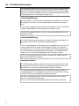 6
6
-
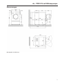 7
7
-
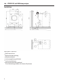 8
8
-
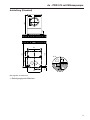 9
9
-
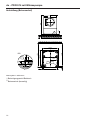 10
10
-
 11
11
-
 12
12
-
 13
13
-
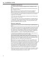 14
14
-
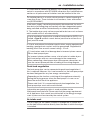 15
15
-
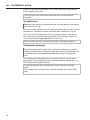 16
16
-
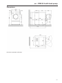 17
17
-
 18
18
-
 19
19
-
 20
20
-
 21
21
-
 22
22
-
 23
23
-
 24
24
-
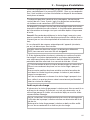 25
25
-
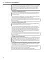 26
26
-
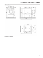 27
27
-
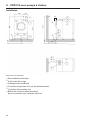 28
28
-
 29
29
-
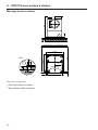 30
30
-
 31
31
-
 32
32
-
 33
33
-
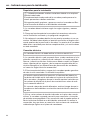 34
34
-
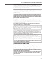 35
35
-
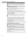 36
36
-
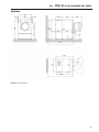 37
37
-
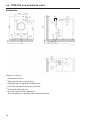 38
38
-
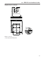 39
39
-
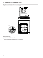 40
40
-
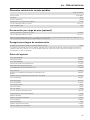 41
41
-
 42
42
-
 43
43
-
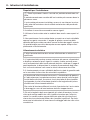 44
44
-
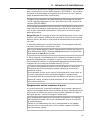 45
45
-
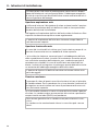 46
46
-
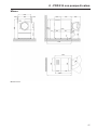 47
47
-
 48
48
-
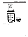 49
49
-
 50
50
-
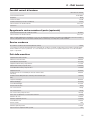 51
51
-
 52
52
-
 53
53
-
 54
54
-
 55
55
-
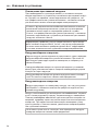 56
56
-
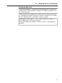 57
57
-
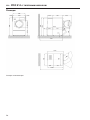 58
58
-
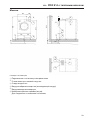 59
59
-
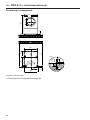 60
60
-
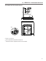 61
61
-
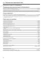 62
62
-
 63
63
-
 64
64


en otros idiomas
- français: Miele PDR 914 HP
- italiano: Miele PDR 914 HP
- Deutsch: Miele PDR 914 HP
Artículos relacionados
-
Miele PDR 922 Guía de instalación
-
Miele PDR 928 G Guía de instalación
-
Miele PDR 922/522 EL Commercial Dryer Guía de instalación
-
-
Miele PDR 918 Guía de instalación
-
Miele PDR 510 COP Installation Plan
-
-
-
-
Otros documentos
-
Whirlpool IDCE 8454 A ECO (EU) Guía del usuario
-
-
Indesit EDPA 745 A ECO (EU) Guía del usuario
-
-
Tecnosystemi AQUA SPLIT 11 lt EF 7 - 11 - 15 - 20 L mini pump El manual del propietario
-
Teltonika TeltoCharge EV Charger Telto Charge Slat Grey Manual de usuario