Benelli Super Vinci Black Use and Maintenance Manual
- Tipo
- Use and Maintenance Manual

VINCI
Warranty | Owner’s Manual | Spare Parts
Garanzia | Uso e Manutenzione | Parti di Ricambio
G0596600 - 01/2020
Printed on ecological paper using solar energy
Benelli Armi S.p.A.
Via della Stazione 50, 61029 Urbino (PU) - Italy
ph. +39 0722 3071 | fax +39 0722 307206
www.benelli.it | [email protected]
Benelli USA Corporation
17603 Indian Head Highway, Accokeek, MD 20607 - 2501
ph. 301-283-6981 | fax 301-283-6988
www.benelliusa.com
Ship Warehouse:
901 8th Street, Pocomoke, MD 21851


Garanzia ............................................... I
Uso
•
Manutenzione
........................ 1
Parti di Ricambio ............................... 133
Warranty .............................................. III
Use
•
Maintenance
........................... 23
Spare Parts .......................................... 133
Garantie ............................................... V
Usage
•
Entretien
.............................. 45
Pièces de Rechange .......................... 133
Garantie ............................................... VII
Gebrauch
•
Wartung
........................ 67
Ersatzteile ............................................ 133
Garantía ............................................... IX
Uso
•
Manutención
.......................... 89
Piezas de Recambio .......................... 133
Гаранти
я
............................................... XI
Использование • Техобслуживание
.. 111
Каталог запчастей
........................... 133
Le informazioni riportate possono essere
soggette a migliorie o cambiamenti in
qualsiasi momento senza preavviso da
parte di Benelli Armi S.p.A.
Benelli Armi S.p.A. reserves the right to
improve or modify the information provided
at any time, without prior notice.
IT
EN
DE
FR
ES
RU

I
IT
GARANZIA ITALIA ED EUROPA
Benelli Armi S.p.A. garantisce i propri fucili e le proprie carabine contro difetti di fabbricazione e di materiale, relativi alle sole parti metalliche e ai componenti con tratta-
mento BE.S.T. Il prodotto coperto dalla garanzia sarà riparato gratuitamente - fatta eccezione per eventuali spese di spedizione a carico dell'acquirente - dal Centro Assistenza
di Benelli di Urbino o dai Riparatori autorizzati Benelli. In nessun caso l'acquirente avrà diritto alla sostituzione dell'arma completa. Sono esclusi dalla presente garanzia
tutti i danni provocati da negligenza, da mancata manutenzione, da manomissione, da riparazione effettuata da personale non autorizzato, dall'utilizzo di munizioni non
conformi alle Norme Internazionali, dalle munizioni caricate manualmente e/o ricaricate, da uso improprio dell'arma, non conforme alle avvertenze riportate sul libretto di
Uso e Manutenzione o comunque causati da fattori estranei al normale utilizzo/funzionamento dell'arma stessa.
Per aver diritto alla garanzia, collegarsi al sito Benelli www.benelli.it alla voce "Garanzia" e seguirne le istruzioni.
Si ricorda di allegare copia dello scontrino di acquisto. Un mancato invio dello scontrino di acquisto o assenza dei dati di registrazione darà diritto solo alla garanzia lega-
le prevista nel proprio paese.
ATTESTAZIONE DI COLLAUDO
La Benelli Armi S.p.A. dichiara che tutti i suoi prodotti sono stati regolarmente sot-
toposti al collaudo del Banco Nazionale di Prova, come attestato dai punzoni uffi-
ciali impressi sulla carcassa e sulla canna.
PRIVACY
Benelli armi S.p.A. tratterà i vostri dati personali con la massima cura secondo quan-
to stabilito dal Regolamento (UE) 2016/679 (“GDPR”).
La nostra Informativa sulla privacy è disponibile all'indirizzo www.benelli.it - sezione
privacy per avere informazioni su come raccogliamo i dati sul vostro conto, l'uso che
ne viene fatto e come potete accedervi e gestirli.
Per qualsiasi informazione potete contattarci al seguente indirizzo email:
GARANZIA CANADA
Benelli Armi S.p.A. garantisce i propri fucili e le proprie carabine contro difetti di fabbricazione e di materiale, relativi alle sole parti metalliche e ai componenti con tratta-
mento BE.S.T. Il prodotto coperto dalla garanzia sarà riparato gratuitamente - fatta eccezione per eventuali spese di spedizione a carico dell'acquirente - dal Centro Assistenza
di Benelli di Urbino o dai Riparatori autorizzati Benelli. In nessun caso l'acquirente avrà diritto alla sostituzione dell'arma completa. Sono esclusi dalla presente garanzia
tutti i danni provocati da negligenza, da mancata manutenzione, da manomissione, da riparazione effettuata da personale non autorizzato, dall'utilizzo di munizioni non
conformi alle Norme Internazionali, dalle munizioni caricate manualmente e/o ricaricate, da uso improprio dell'arma, non conforme alle avvertenze riportate sul libretto di
Uso e Manutenzione o comunque causati da fattori estranei al normale utilizzo/funzionamento dell'arma stessa.
Per aver diritto alla garanzia, si prega di collegarsi al seguente link: https://www.stoegercanada.ca/support/
ATTESTAZIONE DI COLLAUDO PRIVACY
La Benelli Armi S.p.A. dichiara che tutti i suoi prodotti sono stati regolarmente sot-
toposti al collaudo del Banco Nazionale di Prova, come attestato dai punzoni uffi-
ciali impressi sulla carcassa e sulla canna.
I vostri dati verranno trattati secondo quanto stabilito dalla normativa vigente nel
paese in cui ha sede il distributore.
Per qualsiasi informazione potete rivolgervi al nostro distributore Benelli.

II
GARANZIA USA
Benelli Armi S.p.A. garantisce i propri fucili e le proprie carabine contro difetti di fabbricazione e di materiale, relativi alle sole parti metalliche e ai componenti con tratta-
mento BE.S.T. Il prodotto coperto dalla garanzia sarà riparato gratuitamente - fatta eccezione per eventuali spese di spedizione a carico dell'acquirente - dal Centro Assistenza
di Benelli di Urbino o dai Riparatori autorizzati Benelli. In nessun caso l'acquirente avrà diritto alla sostituzione dell'arma completa. Sono esclusi dalla presente garanzia
tutti i danni provocati da negligenza, da mancata manutenzione, da manomissione, da riparazione effettuata da personale non autorizzato, dall'utilizzo di munizioni non
conformi alle Norme Internazionali, dalle munizioni caricate manualmente e/o ricaricate, da uso improprio dell'arma, non conforme alle avvertenze riportate sul libretto di
Uso e Manutenzione o comunque causati da fattori estranei al normale utilizzo/funzionamento dell'arma stessa.
Per aver diritto alla garanzia, si prega di collegarsi al seguente link: www.benelliusa.com/customer-service/warranty/warranty-registration
ATTESTAZIONE DI COLLAUDO
La Benelli Armi S.p.A. dichiara che tutti i suoi prodotti sono stati regolarmente sot-
toposti al collaudo del Banco Nazionale di Prova, come attestato dai punzoni uffi-
ciali impressi sulla carcassa e sulla canna.
PRIVACY
I vostri dati verranno trattati secondo quanto stabilito dalla normativa vigente nel
paese in cui ha sede il distributore.
Per qualsiasi informazione potete rivolgervi al nostro distributore Benelli.
GARANZIA SPAGNA
Benelli Armi S.p.A. garantisce i propri fucili e le proprie carabine contro difetti di fabbricazione e di materiale, relativi alle sole parti metalliche e ai componenti con tratta-
mento BE.S.T. Il prodotto coperto dalla garanzia sarà riparato gratuitamente - fatta eccezione per eventuali spese di spedizione a carico dell'acquirente - dal Centro Assistenza
di Benelli di Urbino o dai Riparatori autorizzati Benelli. In nessun caso l'acquirente avrà diritto alla sostituzione dell'arma completa. Sono esclusi dalla presente garanzia
tutti i danni provocati da negligenza, da mancata manutenzione, da manomissione, da riparazione effettuata da personale non autorizzato, dall'utilizzo di munizioni non
conformi alle Norme Internazionali, dalle munizioni caricate manualmente e/o ricaricate, da uso improprio dell'arma, non conforme alle avvertenze riportate sul libretto di
Uso e Manutenzione o comunque causati da fattori estranei al normale utilizzo/funzionamento dell'arma stessa.
Per aver diritto alla garanzia, si prega di collegarsi al seguente link: https://www.bbi.es/garantia_benelli
ATTESTAZIONE DI COLLAUDO PRIVACY
La Benelli Armi S.p.A. dichiara che tutti i suoi prodotti sono stati regolarmente sot-
toposti al collaudo del Banco Nazionale di Prova, come attestato dai punzoni uffi-
ciali impressi sulla carcassa e sulla canna.
I vostri dati personali saranno trattati con la massima cura secondo quanto stabilito
dal Regolamento (UE) 2016/679 (“GDPR”).
Per qualsiasi informazione potete rivolgervi al nostro distributore Benelli.

III
WARRANTY - ITALY AND EUROPE
Benelli Armi S.p.A. guarantees its shotguns and rifles against manufacturing and material defects limited to metal parts and components with the BE.S.T. treatment. The pro-
duct covered by the warranty will be repaired free of charge - with the exception of any shipping costs borne by the owner - by the Benelli Service Centre in Urbino or other
authorised Benelli Service Centres. Under no circumstances shall the buyer be entitled to the replacement of the whole firearm. Excluded from this warranty are all dama-
ges caused by negligence, lack of maintenance, tampering, repairs carried out by unauthorised personnel, the use of ammunition that does not comply with International
Standards, ammunition filled and/or refilled manually, improper use of the weapon, not in accordance with the warnings in the Use and Maintenance manual or otherwise
caused by factors not falling within the normal use/operation of the firearm.
To activate warranty coverage, go to the Warranty section of the Benelli website at www.benelli.it and follow the instructions.
Please remember to attach a copy of your sales receipt. Failure to submit the receipt or to provide registration data will only entitle you to the legal warranty provided in your country.
TESTING CERTIFICATE
Benelli Armi S.p.A. declares that all its products have been regularly tested by the
National Proof House as attested by the official punches stamped on the receiver
and the barrel.
PRIVACY
Benelli Armi S.p.A. will process your personal data with the utmost care in accord-
ance with the provisions of Regulation (EU) 2016/679 ("GDPR").
To learn how we collect information about you, how we use it and how you can
access and manage it see our Privacy Policy in the Privacy section at www.benelli.it.
For any information you can contact us at the following email address:
WARRANTY - CANADA
Benelli Armi S.p.A. guarantees its shotguns and rifles against manufacturing and material defects limited to metal parts and components with the BE.S.T. treatment. The pro-
duct covered by the warranty will be repaired free of charge - with the exception of any shipping costs borne by the owner - by the Benelli Service Centre in Urbino or other
authorised Benelli Service Centres. Under no circumstances shall the buyer be entitled to the replacement of the whole firearm. Excluded from this warranty are all dama-
ges caused by negligence, lack of maintenance, tampering, repairs carried out by unauthorised personnel, the use of ammunition that does not comply with International
Standards, ammunition filled and/or refilled manually, improper use of the weapon, not in accordance with the warnings in the Use and Maintenance manual or otherwise
caused by factors not falling within the normal use/operation of the firearm.
To activate the warranty, please go to the following link: https://www.stoegercanada.ca/support/
TESTING CERTIFICATE PRIVACY
Benelli Armi S.p.A. declares that all its products have been regularly tested by the
National Proof House as attested by the official punches stamped on the receiver
and the barrel.
Your data will be processed in accordance with current regulations in the country
the distributor is based in.
For more information you can contact the distributor of Benelli products.
EN

IV
WARRANTY - USA
Benelli Armi S.p.A. guarantees its shotguns and rifles against manufacturing and material defects limited to metal parts and components with the BE.S.T. treatment. The pro-
duct covered by the warranty will be repaired free of charge - with the exception of any shipping costs borne by the owner - by the Benelli Service Centre in Urbino or other
authorised Benelli Service Centres. Under no circumstances shall the buyer be entitled to the replacement of the whole firearm. Excluded from this warranty are all dama-
ges caused by negligence, lack of maintenance, tampering, repairs carried out by unauthorised personnel, the use of ammunition that does not comply with International
Standards, ammunition filled and/or refilled manually, improper use of the weapon, not in accordance with the warnings in the Use and Maintenance manual or otherwise
caused by factors not falling within the normal use/operation of the firearm.
To activate the warranty, please go to the following link: www.benelliusa.com/customer-service/warranty/warranty-registration
TESTING CERTIFICATE
Benelli Armi S.p.A. declares that all its products have been regularly tested by the
National Proof House as attested by the official punches stamped on the receiver
and the barrel.
PRIVACY
Your data will be processed in accordance with current regulations in the country
the distributor is based in.
For more information you can contact the distributor of Benelli products.
WARRANTY - SPAIN
Benelli Armi S.p.A. guarantees its shotguns and rifles against manufacturing and material defects limited to metal parts and components with the BE.S.T. treatment. The pro-
duct covered by the warranty will be repaired free of charge - with the exception of any shipping costs borne by the owner - by the Benelli Service Centre in Urbino or other
authorised Benelli Service Centres. Under no circumstances shall the buyer be entitled to the replacement of the whole firearm. Excluded from this warranty are all dama-
ges caused by negligence, lack of maintenance, tampering, repairs carried out by unauthorised personnel, the use of ammunition that does not comply with International
Standards, ammunition filled and/or refilled manually, improper use of the weapon, not in accordance with the warnings in the Use and Maintenance manual or otherwise
caused by factors not falling within the normal use/operation of the firearm.
To activate the warranty, please go to the following link: https://www.bbi.es/garantia_benelli
TESTING CERTIFICATE
PRIVACY
Benelli Armi S.p.A. declares that all its products have been regularly tested by the
National Proof House as attested by the official punches stamped on the receiver
and the barrel.
Your personal data will be processed with the utmost care in accordance with the
provisions of Regulation (EU) 2016/679 ("GDPR").
For more information you can contact the distributor of Benelli products.

V
GARANTIE ITALIE ET EUROPE
Benelli Armi S.p.A. garantit ses fusils et carabines contre les vices de fabrication et les défauts du matériel, seulement en ce qui concerne les pièces métalliques et les composants
bénéficiant du traitement BE.S.T. Le produit couvert par la garantie sera réparé gratuitement - les éventuels frais d’expédition resteront toutefois à la charge de l’acquéreur - par le
Centre d'assistance de Benelli d’Urbino ou par les réparateurs agréés Benelli. L’arme complète de l’acquéreur ne sera en aucun cas remplacée. Tous les dommages dus à une
négligence, un entretien insuffisant, une modification non autorisée, une réparation effectuée par une personne non agréée, l’utilisation de munitions non conformes aux normes
internationales, de munitions chargées ou rechargées manuellement, l’utilisation inappropriée de l'arme, non conformes aux avertissements figurant dans le manuel d'utilisation
et entretien ou les dommages dus à des facteurs incompatibles avec une utilisation ou un fonctionnement normaux de l'arme ne sont pas couverts par la présente garantie.
Pour avoir droit à la garantie, il faudra vous rendre sur le site de Benelli et enregistrer le fusil sur la page prévue à cet effet (https://www.benelli.it/it/garanzia-online).
Rappelez-vous de joindre une copie du ticket de caisse ou de la facture. Si vous ne vous enregistrez pas et que vous ne fournissez pas une copie du ticket de caisse ou de
la facture, seule la garantie légale propre à chaque pays s’appliquera.
CERTIFICAT DE CONFORMITÉ
Benelli Armi S.p.A. déclare que tous ses produits ont passé avec succès les épreu-
ves du Banc National de Tir des armes et munitions, comme l’attestent les estam-
pilles officielles figurant sur la carcasse et sur le canon.
POLITIQUE DE CONFIDENTIALITÉ
Benelli Armi S.p.A. traitera vos données personnelles avec le plus grand soin confor-
mément à ce qui est établi par le règlement n°2016/679, dit règlement général sur la
protection des données (RGPD).
Vous pouvez consulter notre note d'information sur la politique de confidentialité à
l'adresse www.benelli.it – section Politique de confidentialité – si vous souhaitez obte-
nir des informations sur la façon dont nous collectons les données vous concernant,
l’utilisation qui en est faite et la manière d’y accéder et de les gérer.
Pour toute information complémentaire, vous pouvez nous contacter à l'adresse e-mail
suivante : [email protected]
GARANTIE CANADA
Benelli Armi S.p.A. garantit ses fusils et carabines contre les vices de fabrication et les défauts du matériel, seulement en ce qui concerne les pièces métalliques et les composants
bénéficiant du traitement B.E.S.T. Le produit couvert par la garantie sera réparé gratuitement - les éventuels frais d’expédition resteront toutefois à la charge de l’acquéreur - par le
Centre d'assistance de Benelli d’Urbino ou par les réparateurs agréés Benelli. L’arme complète de l’acquéreur ne sera en aucun cas remplacée. Tous les dommages dus à une
négligence, un entretien insuffisant, une modification non autorisée, une réparation effectuée par une personne non agréée, l’utilisation de munitions non conformes aux normes
internationales, de munitions chargées ou rechargées manuellement, l’utilisation inappropriée de l'arme, non conformes aux avertissements figurant dans le manuel d'utilisation et
entretien ou les dommages dus à des facteurs incompatibles avec une utilisation ou un fonctionnement normaux de l'arme ne sont pas couverts par la présente garantie.
Pour bénéficier de la garantie, veuillez vous connecter à l'adresse suivante : https://www.stoegercanada.ca/support/
CERTIFICAT DE CONFORMITÉ POLITIQUE DE CONFIDENTIALITÉ
Benelli Armi S.p.A. déclare que tous ses produits ont passé avec succès les épreu-
ves du Banc National de Tir des armes et munitions, comme l’attestent les estam-
pilles officielles figurant sur la carcasse et sur le canon.
Vos données seront traitées conformément à ce qui est établi par la réglementation
en vigueur dans le pays de votre distributeur. Pour toute information complémentaire,
vous pouvez vous adresser à notre distributeur Benelli.
FR

VI
GARANTIE ÉTATS-UNIS
Benelli Armi S.p.A. garantit ses fusils et carabines contre les vices de fabrication et les défauts du matériel, seulement en ce qui concerne les pièces métalliques et les composants
bénéficiant du traitement BE.S.T. Le produit couvert par la garantie sera réparé gratuitement - les éventuels frais d’expédition resteront toutefois à la charge de l’acquéreur - par le
Centre d'assistance de Benelli d’Urbino ou par les réparateurs agréés Benelli. L’arme complète de l’acquéreur ne sera en aucun cas remplacée. Tous les dommages dus à une
négligence, un entretien insuffisant, une modification non autorisée, une réparation effectuée par une personne non agréée, l’utilisation de munitions non conformes aux normes
internationales, de munitions chargées ou rechargées manuellement, l’utilisation inappropriée de l'arme, non conformes aux avertissements figurant dans le manuel d'utilisation
et entretien ou les dommages dus à des facteurs incompatibles avec une utilisation ou un fonctionnement normaux de l'arme ne sont pas couverts par la présente garantie.
Pour bénéficier de la garantie, veuillez vous connecter à l'adresse suivante : www.benelliusa.com/customer-service/warranty/warranty-registration
CERTIFICAT DE CONFORMITÉ
Benelli Armi S.p.A. déclare que tous ses produits ont passé avec succès les épreu-
ves du Banc National de Tir des armes et munitions, comme l’attestent les estam-
pilles officielles figurant sur la carcasse et sur le canon.
POLITIQUE DE CONFIDENTIALITÉ
Vos données seront traitées conformément à ce qui est établi par la réglementation
en vigueur dans le pays de votre distributeur.
Pour toute information complémentaire, vous pouvez vous adresser à notre distri-
buteur Benelli.
GARANTIE ESPAGNE
Benelli Armi S.p.A. garantit ses fusils et carabines contre les vices de fabrication et les défauts du matériel, seulement en ce qui concerne les pièces métalliques et les composants
bénéficiant du traitement BE.S.T. Le produit couvert par la garantie sera réparé gratuitement - les éventuels frais d’expédition resteront toutefois à la charge de l’acquéreur - par le
Centre d'assistance de Benelli d’Urbino ou par les réparateurs agréés Benelli. L’arme complète de l’acquéreur ne sera en aucun cas remplacée. Tous les dommages dus à une
négligence, un entretien insuffisant, une modification non autorisée, une réparation effectuée par une personne non agréée, l’utilisation de munitions non conformes aux normes
internationales, de munitions chargées ou rechargées manuellement, l’utilisation inappropriée de l'arme, non conformes aux avertissements figurant dans le manuel d'utilisation
et entretien ou les dommages dus à des facteurs incompatibles avec une utilisation ou un fonctionnement normaux de l'arme ne sont pas couverts par la présente garantie.
Pour bénéficier de la garantie, veuillez vous connecter à l'adresse suivante : https://www.bbi.es/garantia_benelli
CERTIFICAT DE CONFORMITÉ
POLITIQUE DE CONFIDENTIALITÉ
Benelli Armi S.p.A. déclare que tous ses produits ont passé avec succès les épreu-
ves du Banc National de Tir des armes et munitions, comme l’attestent les estam-
pilles officielles figurant sur la carcasse et sur le canon.
Vos données personnelles seront traitées avec le plus grand soin conformément à ce
qui est établi par le règlement n°2016/679, dit règlement général sur la protection
des données (RGPD). Pour toute information complémentaire, vous pouvez vous
adresser à notre distributeur Benelli.

VII
DE
GARANTIE ITALIEN UND EUROPA
Benelli Armi S.p.A. gewährt auf sein Gewehre/Flinten und Karabiner eine Garantie gegen Herstellungs- und Materialfehler, die sich lediglich auf Metallteile und Komponenten
mit BE.S.T.-Behandlung bezieht. Das von der Garantie abgedeckte Produkt wird kostenfrei - mit Ausnahme eventueller, vom Käufer zu tragenden Versandkosten - vom Benelli
Service Center in Urbino oder durch autorisierte Benelli Werkstätten repariert. Der Käufer hat unter keinen Umständen Anspruch auf den Austausch der kompletten Waffe.
Von dieser Garantie ausgeschlossen sind alle Schäden, die durch Fahrlässigkeit, mangelnde Wartung, Manipulation, Reparaturen durch nicht autorisiertes Personal, die
Verwendung von Munition, die nicht den internationalen Normen entspricht, manuell geladene und/oder nachgeladene Munition, unsachgemäßen Gebrauch der Waffe, der
nicht in Übereinstimmung mit den in der Gebrauchs- und Wartungsanleitung angeführten Warnhinweisen erfolgt, oder jedenfalls durch Faktoren verursacht werden, die über
den normalen Gebrauch / Betrieb der Waffe selbst hinausgehen.
Um die Garantie in Anspruch zu nehmen, den Bereich „Garantie“ auf der Website von Benelli www.benelli.it öffnen und den Anweisungen folgen.
Bitte denken Sie daran, eine Kopie Ihres Kaufbelegs beizufügen. Wird der Kaufbeleg nicht beigefügt oder fehlen die Anmeldedaten, haben Sie nur Anspruch auf die in
Ihrem Land gewährte gesetzliche Garantie.
PRÜFSCHEIN
Benelli Armi S.p.A. erklärt, dass alle ihre Produkte sachgemäß vom staatlichen
Beschussamt einer Abnahmeprüfung wurden, was durch die offiziellen Stempel auf
dem Korpus und dem Lauf bestätigt wird.
DATENSCHUTZ
Benelli Armi S.p.A. wird Ihre personenbezogenen Daten gemäß den Bestimmungen
der Verordnung (EU) 2016/679 („GDPR“) mit größter Sorgfalt behandeln.
Unsere Datenschutzerklärung steht unter www.benelli.it - Abschnitt „Datenschutz“
zur Verfügung. Dort erfahren Sie, auf welche Art wir Informationen über Sie sammeln,
wie wir sie verwenden und wie Sie darauf zugreifen und sie verwalten können.
Für sämtliche Informationen können Sie uns unter folgender E-Mail-Adresse kon-
taktieren: [email protected]
GARANTIE KANADA
Benelli Armi S.p.A. gewährt auf sein Gewehre/Flinten und Karabiner eine Garantie gegen Herstellungs- und Materialfehler, die sich lediglich auf Metallteile und Komponenten
mit BE.S.T.-Behandlung bezieht. Das von der Garantie abgedeckte Produkt wird kostenfrei - mit Ausnahme eventueller, vom Käufer zu tragenden Versandkosten - vom Benelli
Service Center in Urbino oder durch autorisierte Benelli Werkstätten repariert. Der Käufer hat unter keinen Umständen Anspruch auf den Austausch der kompletten Waffe.
Von dieser Garantie ausgeschlossen sind alle Schäden, die durch Fahrlässigkeit, mangelnde Wartung, Manipulation, Reparaturen durch nicht autorisiertes Personal, die
Verwendung von Munition, die nicht den internationalen Normen entspricht, manuell geladene und/oder nachgeladene Munition, unsachgemäßen Gebrauch der Waffe, der
nicht in Übereinstimmung mit den in der Gebrauchs- und Wartungsanleitung angeführten Warnhinweisen erfolgt, oder jedenfalls durch Faktoren verursacht werden, die über
den normalen Gebrauch / Betrieb der Waffe selbst hinausgehen.
Um die Garantie in Anspruch zu nehmen, melden Sie sich bitte unter folgendem Link an: https://www.stoegercanada.ca/support/
PRÜFSCHEIN DATENSCHUTZ
Benelli Armi S.p.A. erklärt, dass alle ihre Produkte sachgemäß vom staatlichen
Beschussamt einer Abnahmeprüfung wurden, was durch die offiziellen Stempel auf
dem Korpus und dem Lauf bestätigt wird.
Ihre Daten werden gemäß den geltenden Vorschriften des Landes, in dem der
Vertriebspartner seinen Sitz hat, verarbeitet.
Für weitere Informationen wenden Sie sich bitte an unseren Benelli Vertriebspartner.

VIII
GARANTIE USA
Benelli Armi S.p.A. gewährt auf sein Gewehre/Flinten und Karabiner eine Garantie gegen Herstellungs- und Materialfehler, die sich lediglich auf Metallteile und Komponenten
mit BE.S.T.-Behandlung bezieht. Das von der Garantie abgedeckte Produkt wird kostenfrei - mit Ausnahme eventueller, vom Käufer zu tragenden Versandkosten - vom Benelli
Service Center in Urbino oder durch autorisierte Benelli Werkstätten repariert. Der Käufer hat unter keinen Umständen Anspruch auf den Austausch der kompletten Waffe.
Von dieser Garantie ausgeschlossen sind alle Schäden, die durch Fahrlässigkeit, mangelnde Wartung, Manipulation, Reparaturen durch nicht autorisiertes Personal, die
Verwendung von Munition, die nicht den internationalen Normen entspricht, manuell geladene und/oder nachgeladene Munition, unsachgemäßen Gebrauch der Waffe, der
nicht in Übereinstimmung mit den in der Gebrauchs- und Wartungsanleitung angeführten Warnhinweisen erfolgt, oder jedenfalls durch Faktoren verursacht werden, die über
den normalen Gebrauch / Betrieb der Waffe selbst hinausgehen.
Um die Garantie in Anspruch zu nehmen, melden Sie sich bitte unter folgendem Link an: www.benelliusa.com/customer-service/warranty/warranty-registration
PRÜFSCHEIN
Benelli Armi S.p.A. erklärt, dass alle ihre Produkte sachgemäß vom staatlichen
Beschussamt einer Abnahmeprüfung wurden, was durch die offiziellen Stempel auf
dem Korpus und dem Lauf bestätigt wird.
DATENSCHUTZ
Ihre Daten werden gemäß den geltenden Vorschriften des Landes, in dem der
Vertriebspartner seinen Sitz hat, verarbeitet.
Für weitere Informationen wenden Sie sich bitte an unseren Benelli Vertriebspartner.
GARANTIE SPANIEN
Benelli Armi S.p.A. gewährt auf sein Gewehre/Flinten und Karabiner eine Garantie gegen Herstellungs- und Materialfehler, die sich lediglich auf Metallteile und Komponenten
mit BE.S.T.-Behandlung bezieht. Das von der Garantie abgedeckte Produkt wird kostenfrei - mit Ausnahme eventueller, vom Käufer zu tragenden Versandkosten - vom Benelli
Service Center in Urbino oder durch autorisierte Benelli Werkstätten repariert. Der Käufer hat unter keinen Umständen Anspruch auf den Austausch der kompletten Waffe.
Von dieser Garantie ausgeschlossen sind alle Schäden, die durch Fahrlässigkeit, mangelnde Wartung, Manipulation, Reparaturen durch nicht autorisiertes Personal, die
Verwendung von Munition, die nicht den internationalen Normen entspricht, manuell geladene und/oder nachgeladene Munition, unsachgemäßen Gebrauch der Waffe, der
nicht in Übereinstimmung mit den in der Gebrauchs- und Wartungsanleitung angeführten Warnhinweisen erfolgt, oder jedenfalls durch Faktoren verursacht werden, die über
den normalen Gebrauch / Betrieb der Waffe selbst hinausgehen.
Um die Garantie in Anspruch zu nehmen, melden Sie sich bitte unter folgendem Link an: https://www.bbi.es/garantia_benelli
PRÜFSCHEIN DATENSCHUTZ
Benelli Armi S.p.A. erklärt, dass alle ihre Produkte sachgemäß vom staatlichen
Beschussamt einer Abnahmeprüfung wurden, was durch die offiziellen Stempel auf
dem Korpus und dem Lauf bestätigt wird.
Ihre personenbezogenen Daten werden gemäß den Bestimmungen der Verordnung
(EU) 2016/679 („GDPR“) mit größter Sorgfalt behandelt.
Für weitere Informationen wenden Sie sich bitte an unseren Benelli Vertriebspartner.

IX
GARANTÍA ITALIA Y EUROPA
Benelli Armi S.p.A. garantiza sus escopetas y carabinas contra defectos de fabricación y de material, relativos solo a las partes metálicas y a los componentes con tratamiento
BE.S.T. El producto cubierto por la garantía se reparará gratuitamente - con excepción de los eventuales gastos de envío que estarán a cargo del comprador - en el Centro de
Asistencia Benelli de Urbino o en un Distribuidor autorizado Benelli. El comprador no tendrá derecho, en ningún caso, a la sustitución del arma completa. Quedan exclui-
dos de la presente garantía, todos los daños ocasionados por negligencia, por funcionamiento anómalo, por alteración, por reparación efectuada por personal no autorizado,
por el uso de municiones no conformes a las Normas internacionales, por las municiones cargadas manualmente y/o recargadas, por el uso inadecuado del arma, no confor-
me con las advertencias presentes en el manual de Uso y Mantenimiento o, de todos modos, causados por factores ajenos al uso/funcionamiento normal de dicha arma.
Para tener derecho a la garantía, consultar la opción «Garantía» en el sitio Benelli www.benelli.it y seguir las instrucciones.
Se recuerda que se debe adjuntar la copia del recibo de compra. Si no se envía el recibo de compra o los datos de registro están incompletos, se tendrá derecho solo a la
garantía legal prevista en el propio país.
CERTIFICADO DE PRUEBA
Benelli Armi S.p.A. declara que todos sus productos han sido probados regular-
mente en el Banco Nazionale di Prova (Banco Oficial de Pruebas), como lo certifi-
can los sellos oficiales grabados en la carcasa y en el cañón.
POLÍTICA DE PRIVACIDAD
Benelli armi S.p.A. tratará sus datos personales con la máxima atención en confor-
midad con las disposiciones del Reglamento (UE) 2016/679 (“RGDP”).
Nuestra Nota informativa sobre la privacidad está disponible en la dirección
www.benelli.it - sección privacidad donde se podrá obtener más información sobre la
recogida de los datos personales, el uso que se realiza de los mismos y cómo se puede
acceder y gestionar los mismos.
Para cualquier información, puede contactarnos a través de la dirección de correo
electrónico: [email protected]
GARANTÍA CANADÁ
Benelli Armi S.p.A. garantiza sus escopetas y carabinas contra defectos de fabricación y de material, relativos solo a las partes metálicas y a los componentes con tratamiento
BE.S.T. El producto cubierto por la garantía se reparará gratuitamente - con excepción de los eventuales gastos de envío que estarán a cargo del comprador - en el Centro de
Asistencia Benelli de Urbino o en un Distribuidor autorizado Benelli. El comprador no tendrá derecho, en ningún caso, a la sustitución del arma completa. Quedan exclui-
dos de la presente garantía, todos los daños ocasionados por negligencia, por funcionamiento anómalo, por alteración, por reparación efectuada por personal no autorizado,
por el uso de municiones no conformes a las Normas internacionales, por las municiones cargadas manualmente y/o recargadas, por el uso inadecuado del arma, no confor-
me con las advertencias presentes en el manual de Uso y Mantenimiento o, de todos modos, causados por factores ajenos al uso/funcionamiento normal de dicha arma.
Para tener derecho a la garantía, es necesario hacer clic en el siguiente enlace: https://www.stoegercanada.ca/support/
CERTIFICADO DE PRUEBA POLÍTICA DE PRIVACIDAD
Benelli Armi S.p.A. declara que todos sus productos han sido probados regular-
mente en el Banco Nazionale di Prova (Banco Oficial de Pruebas), como lo certifi-
can los sellos oficiales grabados en la carcasa y en el cañón.
Sus datos serán tratados según las disposiciones de la normativa vigente en el país
donde tiene sede el distribuidor.
Para cualquier información, dirigirse a nuestro distribuidor Benelli.
ES

X
GARANTÍA EE.UU.
Benelli Armi S.p.A. garantiza sus escopetas y carabinas contra defectos de fabricación y de material, relativos solo a las partes metálicas y a los componentes con tratamiento
BE.S.T. El producto cubierto por la garantía se reparará gratuitamente - con excepción de los eventuales gastos de envío que estarán a cargo del comprador - en el Centro de
Asistencia Benelli de Urbino o en un Distribuidor autorizado Benelli. El comprador no tendrá derecho, en ningún caso, a la sustitución del arma completa. Quedan exclui-
dos de la presente garantía, todos los daños ocasionados por negligencia, por funcionamiento anómalo, por alteración, por reparación efectuada por personal no autorizado,
por el uso de municiones no conformes a las Normas internacionales, por las municiones cargadas manualmente y/o recargadas, por el uso inadecuado del arma, no confor-
me con las advertencias presentes en el manual de Uso y Mantenimiento o, de todos modos, causados por factores ajenos al uso/funcionamiento normal de dicha arma.
Para tener derecho a la garantía, es necesario hacer clic en el siguiente enlace: www.benelliusa.com/customer-service/warranty/warranty-registration
CERTIFICADO DE PRUEBA
Benelli Armi S.p.A. declara que todos sus productos han sido probados regular-
mente en el Banco Nazionale di Prova (Banco Oficial de Pruebas), como lo certifi-
can los sellos oficiales grabados en la carcasa y en el cañón.
POLÍTICA DE PRIVACIDAD
Sus datos serán tratados según las disposiciones de la normativa vigente en el país
donde tiene sede el distribuidor.
Para cualquier información, dirigirse a nuestro distribuidor Benelli.
GARANTÍA ESPAÑA
Benelli Armi S.p.A. garantiza sus escopetas y carabinas contra defectos de fabricación y de material, relativos solo a las partes metálicas y a los componentes con tratamiento
BE.S.T. El producto cubierto por la garantía se reparará gratuitamente - con excepción de los eventuales gastos de envío que estarán a cargo del comprador - en el Centro de
Asistencia Benelli de Urbino o en un Distribuidor autorizado Benelli. El comprador no tendrá derecho, en ningún caso, a la sustitución del arma completa. Quedan exclui-
dos de la presente garantía, todos los daños ocasionados por negligencia, por funcionamiento anómalo, por alteración, por reparación efectuada por personal no autorizado,
por el uso de municiones no conformes a las Normas internacionales, por las municiones cargadas manualmente y/o recargadas, por el uso inadecuado del arma, no confor-
me con las advertencias presentes en el manual de Uso y Mantenimiento o, de todos modos, causados por factores ajenos al uso/funcionamiento normal de dicha arma.
Para tener derecho a la garantía, es necesario hacer clic en el siguiente enlace: https://www.bbi.es/garantia_benelli
CERTIFICADO DE PRUEBA POLÍTICA DE PRIVACIDAD
Benelli Armi S.p.A. declara que todos sus productos han sido probados regular-
mente en el Banco Nazionale di Prova (Banco Oficial de Pruebas), como lo certifi-
can los sellos oficiales grabados en la carcasa y en el cañón.
Sus datos personales serán tratados con la máxima atención en conformidad con las
disposiciones del Reglamento (UE) 2016/679 (“RGDP”).
Para cualquier información, dirigirse a nuestro distribuidor Benelli.

XI
RU
ГАРАНТИЯ ИТАЛИЯ И ЕВРОПА
Гарантийные обязательства акционерного общества BENELLI ARMI S.p.A. распространяются только на производственные дефекты металлических деталей и их материалы,
а также на детали с покрытием BE.S.T. Изделия, в отношении которых действуют настоящие гарантийные обязательства, подлежат бесплатному ремонту (за исключением
транспортных расходов, оплачиваемых покупателем) в заводском сервис-центре, находящемся в г. Урбино (Италия) или в ближайшем авторизованном сервис-центре.
Настоящие гарантийные обязательства не распространяются на повреждения, наступившие в результате халатности, отсутствия обслуживания, самовольного изменения
конструкции, ремонта неавторизованным персоналом, использования несоответствующих международным нормам боеприпасов, использования самостоятельно
снаряжённых боеприпасов, нецелевого использования оружия, нарушения правил эксплуатации, изложенных в настоящем Руководстве, а также по любым иным причинам,
не относящимся к нормальной эксплуатации и работе оружия.
Для получения права на гарантийное обслуживание необходимо зайти на сайт www.benelli.it открыть страницу "Гарантия" и заполнить регистрационную форму.
Также необходимо приложить копию кассового чека. На изделия без регистрации и кассового чека распространяются только те гарантийные обязательства, которые
предусмотрены национальным законодательством страны приобретения.
ИСПЫТАНИЯ
Акционерное общество BENELLI ARMI S.p.A. заявляет, что всё изготовленное им
оружие проходит испытания на Национальной испытательной станции, о чём
свидетельствуют официальные клейма, нанесённые на ствол и ствольную коробку.
ПЕРСОНАЛЬНЫЕ ДАННЫЕ
А.О. "Benelli Armi" обрабатывает персональные данные с максимальной
ответственностью в соответствии с Регламентом ЕС 2016/679 (“GDPR”).
Более подробная информация об обработке персональных данных и об их
использовании доступна по адресу: www.benelli.it раздел "конфиденциальность".
Там же вы можете получить доступ к вашим данным и управление ими.
Дополнительную информацию вы можете запросить по адресу: privacy
@
benelli.it
ГАРАНТИЯ КАНАДА
Гарантийные обязательства акционерного общества BENELLI ARMI S.p.A. распространяются только на производственные дефекты металлических деталей и их материалы,
а также на детали с покрытием BE.S.T. Изделия, в отношении которых действуют настоящие гарантийные обязательства, подлежат бесплатному ремонту (за исключением
транспортных расходов, оплачиваемых покупателем) в заводском сервис-центре, находящемся в г. Урбино (Италия) или в ближайшем авторизованном сервис-центре.
Настоящие гарантийные обязательства не распространяются на повреждения, наступившие в результате халатности, отсутствия обслуживания, самовольного изменения
конструкции, ремонта неавторизованным персоналом, использования несоответствующих международным нормам боеприпасов, использования самостоятельно
снаряжённых боеприпасов, нецелевого использования оружия, нарушения правил эксплуатации, изложенных в настоящем Руководстве, а также по любым иным причинам,
не относящимся к нормальной эксплуатации и работе оружия.
Для получения права на гарантийное обслуживание необходимо зайти на сайт
: https://www.stoegercanada.ca/support/
ИСПЫТАНИЯ
ПЕРСОНАЛЬНЫЕ ДАННЫЕ
Акционерное общество BENELLI ARMI S.p.A. заявляет, что всё изготовленное им
оружие проходит испытания на Национальной испытательной станции, о чём
свидетельствуют официальные клейма, нанесённые на ствол и ствольную коробку.
Обработка персональных данных производится в соответствии с
законодательством страны импортёра.
Дополнительную информацию можно получить у импортёра продукции "Бенелли".

XII
ГАРАНТИЯ США
Гарантийные обязательства акционерного общества BENELLI ARMI S.p.A. распространяются только на производственные дефекты металлических деталей и их материалы,
а также на детали с покрытием BE.S.T. Изделия, в отношении которых действуют настоящие гарантийные обязательства, подлежат бесплатному ремонту (за исключением
транспортных расходов, оплачиваемых покупателем) в заводском сервис-центре, находящемся в г. Урбино (Италия) или в ближайшем авторизованном сервис-центре.
Настоящие гарантийные обязательства не распространяются на повреждения, наступившие в результате халатности, отсутствия обслуживания, самовольного изменения
конструкции, ремонта неавторизованным персоналом, использования несоответствующих международным нормам боеприпасов, использования самостоятельно
снаряжённых боеприпасов, нецелевого использования оружия, нарушения правил эксплуатации, изложенных в настоящем Руководстве, а также по любым иным причинам,
не относящимся к нормальной эксплуатации и работе оружия.
Для получения права на гарантийное обслуживание необходимо зайти на сайт
: www.benelliusa.com/customer-service/warranty/warranty-registration
ИСПЫТАНИЯ
Акционерное общество BENELLI ARMI S.p.A. заявляет, что всё изготовленное им
оружие проходит испытания на Национальной испытательной станции, о чём
свидетельствуют официальные клейма, нанесённые на ствол и ствольную коробку.
ПЕРСОНАЛЬНЫЕ ДАННЫЕ
Обработка персональных данных производится в соответствии с законодательством
страны импортёра.
Дополнительную информацию можно получить у импортёра продукции "Бенелли".
ГАРАНТИЯ ИСПАНИЯ
Гарантийные обязательства акционерного общества BENELLI ARMI S.p.A. распространяются только на производственные дефекты металлических деталей и их материалы,
а также на детали с покрытием BE.S.T. Изделия, в отношении которых действуют настоящие гарантийные обязательства, подлежат бесплатному ремонту (за исключением
транспортных расходов, оплачиваемых покупателем) в заводском сервис-центре, находящемся в г. Урбино (Италия) или в ближайшем авторизованном сервис-центре.
Настоящие гарантийные обязательства не распространяются на повреждения, наступившие в результате халатности, отсутствия обслуживания, самовольного изменения
конструкции, ремонта неавторизованным персоналом, использования несоответствующих международным нормам боеприпасов, использования самостоятельно
снаряжённых боеприпасов, нецелевого использования оружия, нарушения правил эксплуатации, изложенных в настоящем Руководстве, а также по любым иным причинам,
не относящимся к нормальной эксплуатации и работе оружия.
Для получения права на гарантийное обслуживание необходимо зайти на сайт
: https://www.bbi.es/garantia_benelli
ИСПЫТАНИЯ
ПЕРСОНАЛЬНЫЕ ДАННЫЕ
Акционерное общество BENELLI ARMI S.p.A. заявляет, что всё изготовленное им
оружие проходит испытания на Национальной испытательной станции, о чём
свидетельствуют официальные клейма, нанесённые на ствол и ствольную коробку.
А.О. "Benelli Armi" обрабатывает персональные данные с максимальной
ответственностью в соответствии с Регламентом ЕС 2016/679 (“GDPR”).
Дополнительную информацию можно получить у импортёра продукции "Бенелли".

1
Indice
USO •
MANUTENZIONE
........................................................... 1
Norme di sicurezza ................................................................... 2
Presentazione ............................................................................ 4
Descrizione tecnica ................................................................... 4
Montaggio ................................................................................. 5
Sicura dell’arma ........................................................................ 7
Caricamento .............................................................................. 7
Sostituzione cartuccia ............................................................... 9
Scaricamento dell’arma ............................................................. 9
Inconvenienti e rimedi .............................................................. 10
Munizionamento ....................................................................... 10
Manutenzione ........................................................................... 10
Smontaggio dell’arma ................................................................ 11
Montaggio dell’arma ................................................................. 13
A
CCESSORI E REGOLAZIONI:
Variazione piega e deviazione arma ......................................... 15
Moduli tubo serbatoio ............................................................... 16
Pulizia moduli serbatoio ........................................................... 17
Montaggio e smontaggio riduttore per modulo
tubo serbatoio M395 equipaggiabile con prolunga ................... 19
Prolunghe modulo tubo serbatoio M395 ................................... 19
Strozzatore interno .................................................................... 20
Regolazione mirino canna “Slug” .............................................. 21
Regolazione tacca di mira “Rifle Sight” ..................................... 22
Regolazione tacca di mira “Ghost Sight” ................................... 22
Sostituzione mirino ................................................................... 22
PARTI DI RICAMBIO .................................................................. 133
Dati soggetti a modifiche senza impegno di preavviso.
SALVO DIVERSE E SPECIFICHE INDICAZIONI, IL TESTO E LE
ILLUSTRAZIONI DEL PRESENTE MANUALE HANNO SEMPRE
COME RIFERIMENTO LA VERSIONE DESTRA IN CALIBRO
12
DEL FUCILE DESCRITTO.
IT

2
NORME DI SICUREZZA
AVVERTENZA: SI PREGA DI LEGGERE IL PRE-
SENTE MANUALE PRIMA DI MANEGGIARE
L’ARMA.
AVVERTENZA: SE MANEGGIATE NON COR-
RETTAMENTE, LE ARMI DA FUOCO POSSONO
ESSERE PERICOLOSE, NONCHÈ POTENZIALE
CAUSA DI GRAVI ED IRREPARABILI DANNI. LE
NORME DI SICUREZZA QUI RIPORTATE VO-
GLIONO ESSERE UN IMPORTANTE RICHIAMO
ALLA RESPONSABILITÀ CHE RICADE SUI POS-
SESSORI E GLI UTILIZZATORI DI ARMI DA
FUOCO.
1. NON PUNTARE MAI L’ARMA CONTRO UNA
DIREZIONE CHE NON SIA PIÙ CHE SICURA.
Non puntare mai la canna dell’arma
contro sé stessi o contro un’altra per-
sona. Questo è di basilare importan-
za quando si carica o scarica l’arma.
Quando ci si accinge a sparare ad un
bersaglio, accertarsi di cosa vi sia die-
tro di esso. I proiettili possono supe-
rare 1,5 km di distanza. Se si manca
il bersaglio o se il proiettile lo trapas-
sa, dovete accertarvi che lo sparo non
abbia causato danni o lesioni a qualcuno.
2. MANEGGIARE SEMPRE L’ARMA COME SE
FOSSE CARICA.
Mai dare per scontato che l’arma sia scarica.
L’unico modo sicuro per accertarsi che l’arma
abbia la camera vuota è quello di aprirla e verifi-
care visivamente e fisicamente che non vi siano
presenti proiettili. Rimuovere o scaricare il serba-
toio non significa che l’arma sia scarica o non
possa sparare. Fucili e carabine possono essere
controllati rimuovendo tutti i proiettili e successi-
vamente aprendo ed ispezionando la camera di
scoppio in modo tale da poter effettuare un’ispe-
zione completa ed assicurarsi che non vi siano
rimasti colpi all’interno.
3. CUSTODIRE L’ARMA IN UN LUOGO SICURO
E NON ACCESSIBILE AI BAMBINI.
E’ vostro compito assicurarvi che i minori o altre
persone non autorizzate non abbiano accesso
all’arma. Per ridurre il rischio di incidenti ai
minori, scaricate l’arma, mettetela
sotto chiave e riponete le munizioni
in una separata sede e sempre sotto
chiave. Tenere sempre presente che i
dispositivi utilizzati per prevenire
incidenti - es. lucchetti per armi,
chiusure per camere di scoppio ecc.
non sono sufficienti ad impedire che
altri possano utilizzare l’arma o uti-
lizzarla in modo improprio. La custodia dell’arma
in una cassetta di sicurezza apposita in acciaio
sarebbe l’ideale per ridurre la probabilità che
minori o persone non autorizzate possano utiliz-
zare l’arma in modo improprio.
4. MAI SPARARE CONTRO SPECCHI D’ACQUA
O SU SUPERFICI DURE.
Sparare contro specchi d’acqua,
contro una roccia o altre superfici
dure aumenta il rischio di rimbalzi
o frammentazioni dei proiettili,
che può voler dire colpire bersagli non voluti o
limitrofi.
5. CONOSCERE LE CARATTERISTICHE DI SICU-
REZZA DELL’ARMA CHE STATE USANDO,
TENENDO PRESENTE CHE I DISPOSITIVI DI
SICUREZZA NON SOSTITUISCONO LE PRO-
CEDURE DI UN MANEGGIO DELL’ARMA IN
SICUREZZA.
Non affidarsi esclusivamente ai dispositivi di
sicurezza al fine di prevenire incidenti. E’ di asso-
luta importanza che conosciate ed osserviate le
caratteristiche di sicurezza dell’arma che state
maneggiando; gli incidenti comunque, possono
essere maggiormente evitati se si seguono le pro-
cedure di un maneggio sicuro dell’arma, conte-
nute nelle regole di sicurezza e all’interno di que-
sto manuale.
Per familiarizzare ulteriormente con l’uso appro-
priato di questa o altre armi, si consiglia di segui-
re un corso sulla sicurezza delle armi tenuto da
un professionista del settore, esperto in tecniche
d’uso e procedure di sicurezza.
6. CONSERVARE L’ARMA IN MODO APPRO-
PRIATO.
Custodire l’arma in modo che non si
accumuli sporco o polvere nelle
parti meccaniche. Seguendo le istru-
zioni contenute in questo manuale,
pulire e lubrificare l’arma dopo ogni
utilizzo per prevenire corrosione, danni alla
canna o accumulo di impurità che possano
impedire all’arma di funzionare in caso di neces-
sità. Controllare sempre l’interno e la camera di
S
t
o
e
g
e
r

3
IT
scoppio prima di caricare l’arma per accertarsi
che siano puliti e privi di ostruzioni. Sparare
quando vi siano ostruzioni nella canna o nella
camera di scoppio può causare l’esplosione della
canna e ferire voi o altre persone vicine. Nel caso
si avverta un rumore anomalo durante lo sparo
smettere immediatamente di sparare, mettere la
sicura e scaricare l’arma.
Accertarsi che la camera e la canna siano libere
da eventuali ostruzioni, come ad es. un proiettile
bloccato all’interno della canna a causa di muni-
zioni difettose o inadatte.
7. UTILIZZARE MUNIZIONI APPROPRIATE.
Utilizzare solo munizioni di fabbrica, nuove
munizioni realizzate secondo le seguenti specifi-
che industriali: CIP (Europa e altri paesi),
SAAMI® (U.S.A.). Assicurarsi che i proiettili
siano del calibro o del tipo adatti all’arma utiliz-
zata. Il calibro dell’arma è contrassegnato chia-
ramente sulla canna del fucile o sul carrello o
canna della pistola.
L’utilizzo di munizioni ricaricate o ricostruite
può aumentare la probabilità di pressione ecces-
siva sulla cartuccia, esplosione del fondello o
altri difetti delle munizioni che possano causare
danni all’arma e ferire voi o altre persone vicine.
8. INDOSSARE SEMPRE OCCHIALI DI PROTE-
ZIONE E TAPPI PER LE ORECCHIE QUANDO
SI SPARA.
La probabilità che gas, polvere da
sparo o frammenti metallici colpi-
scano e feriscano il tiratore mentre
spara, è remota, ma nell’evenienza
che questo succeda, i danni possono essere
gravi, inclusa la possibilità di perdere la vista.
Quando spara, il tiratore deve sempre indossare
occhiali di protezione ad alta resistenza. Tappi
per le orecchie o altri tipi di protezione di alta
qualità aiutano a ridurre il rischio di danni pro-
vocati dallo sparo.
9. NON ARRAMPICARSI MAI SU ALBERI, RECIN-
ZIONI O OSTACOLI CON L’ARMA CARICA.
Aprire e svuotare la camera dell’ar-
ma e mettere la sicura prima di
arrampicarsi o scendere da alberi o
prima di scavalcare recinti o saltare
fossati o altri ostacoli. Non tirare o
spingere l’arma verso se stessi o verso un’altra
persona. Scaricare sempre l’arma e controllare
visivamente e fisicamente che il serbatoio, il
meccanismo di ricarica e la camera siano scari-
chi e che l’arma abbia l’otturatore aperto prima
di darla in mano ad un’altra persona. Non pren-
dere mai un’arma da un’altra persona a meno
che non sia scarica, controllata fisicamente e
visivamente per accertarsi che sia effettivamente
scarica e comunque prendere l'arma solo se
aperta.
10. EVITARE L’USO DI BEVANDE ALCOLICHE O
MEDICINALI CHE POSSANO DIMINUIRE I
RIFLESSI E L’AUTOCONTROLLO MENTRE SI
SPARA.
Non bere quando si spara. Se si
assumono medicinali che possano
diminuire i riflessi o l’autocontrollo,
non maneggiare armi mentre si è
sotto l’effetto del medicinale.
11. NON TRASPORTARE MAI UN’ARMA CARICA.
Scaricare sempre l’arma prima di
riporla in un veicolo (camera e ser-
batoio vuoti). Cacciatori e tiratori
devono caricare l’arma una volta
giunti a destinazione, e solo quando
sono sul punto di sparare. Se si detiene un’arma
per difesa personale, lasciare la camera scarica
riduce la possibilità di uno sparo involontario.
12. AVVERTENZE SULL’ESPOSIZIONE AL PIOMBO.
Scaricare l’arma in aree con scarsa ventilazione,
pulire armi o maneggiare munizioni può com-
portare una esposizione al piombo e ad altre
sostanze che possono causare danni alla respira-
zione, danni all’apparato riproduttivo ed altri
gravi danni fisici. Sostare sempre in aree con
buona ventilazione. Lavare accuratamente le
mani dopo l’esposizione.
AVVERTENZA: è VOSTRA responsabilità cono-
scere e rispettare le leggi locali e statali che rego-
lamentano il commercio, il trasporto e l’uso delle
armi nel vostro paese.
AVVERTENZA: questa arma può togliere la vita a
voi e agli altri! Siate sempre estremamente atten-
ti nel maneggiare l’arma. Un incidente è quasi
sempre la conseguenza del mancato rispetto
delle norme di sicurezza dell’arma.

4
Presentazione
Benelli ha posto numerose pietre miliari nel processo
evolutivo delle armi da sparo, in particolar modo per
quanto riguarda i semiautomatici a canna liscia.
Innovazione continua, tecnologia all’avanguardia, rigi-
di controlli di qualità, fabbricazione eccellente, orgo-
glio in un lavoro fatto a regola d’arte e costante impe-
gno nel soddisfare le esigenze dell’utente finale - questi
gli elementi che permettono al team Benelli di trasfor-
mare idee rivoluzionarie in armi apprezzate per le loro
prestazioni sul campo, affidabilità balistica e design
unico.
L’inventiva di solito viaggia di pari passo con la sempli-
cità e l’otturatore inerziale ne è un degno esempio. Il
nostro nuovo semiautomatico ha un’anima inerziale.
Un semiautomatico così innovativo che presenta carat-
teristiche uniche, oltre ad affidabilità, facilità d’uso, faci-
le manutenzione, e Moduli intercambiabili.
Oltre a ciò l’arma presenta un rinculo ridotto, alta resi-
stenza ai fattori ambientali e molto altro…. dettagli inte-
ressanti che scoprirete leggendo il manuale di manu-
tenzione ma, soprattutto, quando sparerete con il vostro
nuovo fucile Vinci.
Siamo sicuri che questo fucile vi appassionerà sempre
di più, sparo dopo sparo.
Descrizione tecnica
Il semiautomatico Vinci utilizza un nuovo Sistema
Inerziale che sfrutta l’energia cinetica del rinculo, nello
stesso modo dei fucili Benelli tradizionali attualmente
disponibili sul mercato.
Il design è del tutto innovativo, e basato su un concetto
modulare. Tutte le parti essenziali sono costituite da
moduli separati da montare con una sequenza di movi-
menti molto semplice, senza alcun bisogno di utensili.
Questa è la nuova filosofia Vinci, unica nel suo genere.
Un fucile che nasce dalla semplice unione dei moduli
Affusto, Calcio, Serbatoio e Canna.
Una vera rivoluzione! Tutte le fasi necessarie per un cor-
retto funzionamento dell’arma - messa in sicura, aper-
tura, espulsione e ricarica - in un unico gruppo.
La massa necessaria al funzionamento inerziale è con-
centrata nell’otturatore rotante, alloggiato all’interno del
fodero insieme alla testina di chiusura rotante, l’espul-
sore e la molla biella, a formare un unico modulo.
Questo significa notevoli vantaggi in termini di equili-
brio, stabilità, affidabilità nel funzionamento e facilità
nel montaggio, smontaggio e manutenzione.
Questa soluzione di tecnica innovativa ridisegna com-
pletamente il design strutturale del fucile, facendo del
modulo canna, insieme al fodero, un elemento di sup-
porto per l’intero fucile.
Il modulo calcio è alloggiato nella parte posteriore del
fodero tramite un innesto rapido che consente di perso-
nalizzare piega e deviazione a propria scelta, grazie ad
un unico piastrino intercambiabile e facilmente sostitui-
bile.
Il sistema ad innesto rapido del calcio non necessita l’u-
tilizzo di utensili: tramite una semplice rotazione
manuale è possibile montarlo e smontarlo facilmente,
cambiandolo in base all’uso dell’arma.
Il calcio è fissato alla canna tramite il fodero; ciò signi-
fica che il concetto della carcassa è stato superato,
dando origine ad un nuovo elemento che possiamo
definire “affusto”, il quale svolge una tripla funzione:
astina, per garantire la presa dell’arma; carcassa, per
sostenere il meccanismo di scatto, infine il sistema di
espulsione e incameramento cartucce e il gruppo guar-
dia, come protezione per il grilletto.
L’affusto, così configurato, è collegato in maniera sem-
plice al modulo canna senza viti o perni passanti, ma
con il fissaggio della parte frontale tramite delle alette
incorporate in un manicotto scorrevole, mentre il retro
è fissato al piastrino di variazione piega.
Il gruppo scatto è posizionato dentro l’affusto al livello
del gruppo guardia, mentre nella parte frontale si trova
il modulo serbatoio, collegato al modulo canna tramite
semplice rotazione. Montaggio e sostituzione sono fasi
molto semplici che non richiedono l’ausilio di utensili
né di attrezzature.
I moduli serbatoio possono essere di lunghezza diversa
e contenere diverse quantità di cartucce che variano a
secondo dell’utilizzo e delle leggi vigenti che discipli-
nano l’uso delle prolunghe serbatoio.
La grande innovazione tecnologica del fucile Vinci non
consiste solo nella rivoluzionaria struttura di supporto,
ma anche nel gruppo Carcassa, Tubo serbatoio, Astina e
Canna fissato tramite alette e tappi e nell’assemblaggio
ad innesto rapido di moduli singoli.
Particolare attenzione è stata rivolta all’ergonomia fun-
zionale dell’affusto, della manetta, del sistema cut-off
che facilitano l’apertura dell’otturatore e consentono
l’inserimento ambidestro della leva discesa cartuccia e
semplificano lo scaricamento manuale agendo dall’e-
sterno sulla leva fermo cartuccia.
Grazie all’alto livello di perfezione raggiunto, il funzio-
namento del fucile Vinci è garantito dall’ampia gamma
di cartucce standard CIP che mantengono l’energia
cinetica necessaria per un ciclo completo di ricarica
automatica.
Approfonditi esperimenti balistici di laboratorio e speci-
fici test pratici confermano che per un corretto funzio-
namento dell’arma il valore minimo di energia cinetica
sviluppato da una cartuccia calibro 12 è di 200 kgm per
i modelli Vinci Cordoba e Vinci SuperSport, 230 kgm
per altri modelli del Vinci e 240 kgm per il modello
SuperVinci. I valori sono stati misurati su canna mano-
metrica ad 1 metro dalla volata.

Montaggio
(da fucile imballato)
Componenti confezione (fig. 1):
a) Modulo Affusto/Modulo Tubo Serbatoio
b) Modulo Canna/Modulo Otturatore
c) Modulo Calcio
d) Modulo Tubo Serbatoio (solo versioni M395-M515-
M640)
AVVERTENZA: ricordarsi di rimuovere il copricanna di
plastica prima di utilizzare il fucile (fig. 2).
Procedura di montaggio dell’arma
1) Montare il calcio sulla canna, allineando il punto
bianco di riferimento con la linea di mira del fodero
(fig. 3).
2) Inserire il calcio sul fodero fino a battuta, assicuran-
dosi che il modulo otturatore sia posizionato corret-
tamente all’interno del modulo canna (figg. 4-5).
3) Qualora il modulo sia posizionato scorrettamente
premere verso il basso con il pollice il piastrino bat-
tuta-otturatore (fig. 6) per sbloccare l’aletta superio-
re e arretrare l’otturatore a fine corsa (fig. 7).
5
3
2
1
cad
b
6
5
4
OK
NO
7
IT

6
4) Mantenere l’allineamento punto bianco e linea di
mira sul fodero e ruotare con energia di 90° in senso
orario il calcio stesso fino a fine corsa (fig. 8); (zigri-
no superiore calcio allineato a linea di mira fodero -
fig. 9).
5) Prendere l'affusto e accertarsi che il punto bianco di
riferimento per il montaggio sia ben visibile all'in-
terno dell'asola inferiore posizionata vicino alla
matricola (fig. 10).
ATTENZIONE: se il punto bianco è coperto dal pulsan-
te di montaggio/ smontaggio arma (fig. 11), è sufficien-
te premere a fondo il pulsante stesso e ruotare in senso
antiorario il tappo serbatoio (fig. 12), fino alla corretta
posizione per il montaggio dell'arma: punto bianco visi-
bile.
6) Accostare l'affusto al modulo canna/otturatore, in
posizione verticale, in modo da far combaciare l'in-
cavo presente sul lato destro dell'affusto con il punto
bianco presente sul fodero (fig. 13).
7) Mantenere accostati i due moduli e spingere l'affusto
con forza verso il calcio, possibilmente in appoggio
su un piano di contrasto (fig. 14); ruotare, quindi, in
senso orario il tappo serbatoio (fig. 15), finché il pul-
sante di montaggio/ smontaggio arma non si posizio-
ni come indicato in fig. 11.
9
8
12
11
10 13
14

8) Per accertarsi che tutte le operazioni siano state ese-
guite correttamente, aprire e richiudere l'otturatore
tramite la relativa manetta di armamento: l'otturatore
deve scorrere liberamente all'interno del fodero (fig.
16).
A questo punto il montaggio è completato.
Sicura dell’arma
Il pulsante di sicura "a traversino" è posizionato sulla
parte anteriore della guardia. Per inserire la sicura pre-
mere il pulsante: a sicura inserita non si deve vedere
l'anello rosso che indica la posizione di sparo (figg.
17-18).
Caricamento
Prima di effettuare qualunque tipo di intervento sul
fucile, accertarsi sempre che camera di scoppio e ser-
batoio siano completamente vuoti!
(Leggere attentamente le istruzioni di caricamento e sca-
ricamento dell’arma).
ATTENZIONE: accertarsi che l’arma sia dotata di
modulo tubo serbatoio con numero di cartucce con-
sentito dalle disposizioni vigenti nel paese ove la si uti-
lizzi.
Procedura di caricamento
ATTENZIONE: l'arma deve essere in sicura (vedi
“Sicura dell'arma”) e con cane armato (per consentire
alla leva fermo cartuccia di bloccare le cartucce intro-
dotte nel serbatoio).
ATTENZIONE: per maggior sicurezza, verificare sem-
pre che l'arma sia scarica aprendo l’otturatore.
Riportare poi l'otturatore in chiusura.
7
15
16
19
17
18
20
IT

8
1) La leva-discesa-cartuccia deve presentare il settore
marcato in rosso ben visibile (fig. 19). Se necessario,
portarla nella giusta posizione premendo il pulsante-
leva-fermo-cartuccia (fig. 20) e aprendo contempo-
raneamente a mano l'otturatore, da riposizionare
poi in chiusura.
2) Con otturatore chiuso e cane armato rovesciare l'ar-
ma (orientando la canna verso il basso).
3) Infilare una cartuccia a fondo nel serbatoio (fig. 21)
finchè la leva-fermo-cartuccia aggancia automatica-
mente la cartuccia, trattenendola (fig. 22).
Ripetere l'operazione sino al completo caricamento del
serbatoio.
ATTENZIONE: il caricamento del serbatoio deve essere
effettuato sempre con il cane armato, per consentire alla
leva-fermo-cartuccia di bloccare le cartucce introdotte
nel serbatoio stesso.
A questo punto l'arma non può ancora sparare: si deve
introdurre una cartuccia in canna, operando come
segue:
1) Aprire l'otturatore e trattenerlo in tale posizione men-
tre si introduce contemporaneamente una cartuccia
in canna attraverso la finestra di espulsione del bos-
solo (fig. 23).
2) Rilasciare l'otturatore che, scorrendo in avanti, inca-
mera la cartuccia e si arresta nella posizione di chiu-
sura (fig. 24).
ATTENZIONE: anche se l'arma è in sicura, durante que-
sta operazione è opportuno orientare la canna in dire-
zione di sicura prudenza (vedi “Sicura dell’arma”).
A questo punto l'arma è carica: portando la sicura in
posizione di sparo (anello rosso visibile) l'arma è pron-
ta a sparare.
21 24
2522
23 26

Sostituzione cartuccia
(Operazione da effettuarsi con arma in sicura - vedi
"Sicura dell'arma" - e con canna orientata in direzione
di sicura prudenza).
Per sostituire una cartuccia già incamerata, si possono
seguire due procedure:
A) introduzione manuale della nuova cartuccia;
B) azionamento della leva-discesa- cartuccia.
A) - introduzione manuale della cartuccia
1) Appoggiare il calcio sull'anca ed aprire l'otturatore:
la cartuccia in camera viene estratta ed espulsa (fig.
25).
2) Introdurre in canna, anche parzialmente, la nuova
cartuccia attraverso la finestra di espulsione (fig. 24),
rilasciando poi l'otturatore.
B) - azionamento della leva-discesa-cartuccia
1) Appoggiare il calcio sull'anca, premere la leva-
discesa-cartuccia (fig. 26) ed aprire l'otturatore: la
cartuccia in camera viene estratta ed espulsa (fig. 25).
2) Lasciare libera la manetta: si ottiene così il passaggio
rapido di una cartuccia dal serbatoio alla camera di
scoppio.
Scaricamento dell’arma
(Operazione da effettuarsi con arma in sicura - vedi
“Sicura dell'arma” - e con canna orientata in direzione
di sicura prudenza).
Per scaricare l'arma operare come segue:
1) Inserire la sicura (fig. 27) ed aprire manualmente l'ot-
turatore: la cartuccia in camera di scoppio viene
estratta ed espulsa (fig. 25).
2) Lasciare la manetta e riportare l'otturatore in chiu-
sura (fig. 28).
3) Capovolgere l'arma e, spingendo l'elevatore indietro
verso il basso, premere e contemporaneamente tira-
re indietro la parte posteriore della leva-fermo-car-
tuccia (fig. 29).
4) Le cartucce del serbatoio usciranno una ad una.
In alternativa:
1) Inserire la sicura (fig. 27) ed aprire manualmente l'ot-
turatore: la cartuccia in camera di scoppio viene
estratta ed espulsa (fig. 25).
2) Lasciare la manetta e riportare l'otturatore in chiu-
sura (fig. 28).
3) Capovolgere l'arma e, spingendo l'elevatore verso il
basso, premere (dall'interno dell'affusto) il pulsante-
leva-fermo-cartuccia (fig. 30).
4) La cartuccia del serbatoio uscirà, cadendo nella
mano; si deve premere la leva-fermo-cartuccia per
ogni cartuccia che si vuol togliere dal serbatoio.
AVVERTENZA: l'arma può venir scaricata anche ripe-
tendo più volte l'azione descritta al punto "B" del capi-
tolo "Sostituzione cartuccia".
9
27
28
30
29
IT

10
Inconvenienti e rimedi
Prima di effettuare qualunque tipo di intervento sull'ar-
ma, accertarsi sempre che camera di scoppio e tubo
serbatoio siano completamente vuoti! (Leggere attenta-
mente le istruzioni di caricamento e scaricamento del-
l'arma).
Se il fucile non spara
1) Controllare la sicura: se inserita, spingere il pulsante
nella posizione di fuoco.
2) Controllare che la cartuccia sia in canna. Se neces-
sario, introdurre una cartuccia seguendo le istruzioni
relative al caricamento.
3) Controllare il meccanismo di sparo. Se necessario,
procedere alla sua pulizia e lubrificazione.
Munizionamento
L’automatico Benelli utilizza per il suo funzionamento
l'energia cinetica del rinculo dell'arma.
Utilizzare sempre cartucce che garantiscano un rincu-
lo sufficiente per il completo automatismo di riarmo.
AVVERTENZA: all'inizio dell'uso (fucile nuovo) può
essere necessario un breve periodo di rodaggio prima
che l'arma funzioni perfettamente anche con cariche
leggere. In presenza di problemi di funzionamento, è
opportuno sparare a titolo di rodaggio tre o quattro sca-
tole di cartucce con carica standard.
Munizioni da usare
Il funzionamento dell’arma è garantito con cartucce di
lunghezza massima 58 mm (camera 2” 3/4 - 70 mm),
66 mm (camera 3” - 76 mm) o 78 mm (camera 3” 1/2 -
89 mm solo per modello SuperVinci), a chiusura orlata
o stellare e caricate con pallini sia di piombo che di
acciaio.
Benelli consiglia l’utilizzo di munizioni caricate a palli-
ni per le canne con bindella e le munizioni a palla per
le canne slug.
Questa indicazione non è obbligatoria ma assicura il rag-
giungimento delle migliori prestazioni.
ATTENZIONE: non usare mai cartucce con bossolo la
cui lunghezza superi quella della camera di scoppio!
La mancata osservanza di questa regola comporta
gravi conseguenze sia per il tiratore che per l'arma.
I fucili Benelli non richiedono regolazioni per l’utilizzo
di qualsiasi munizionamento.
Utilizzare sempre cartucce che garantiscano un rincu-
lo sufficiente al completo riarmo dell'arma (vedi para-
grafo “Descrizione Tecnica” pag. 4).
Tutti i fucili Benelli sono sottoposti alla prova forzata di
1370 bar presso il Banco Nazionale di Prova di
Gardone Valtrompia (Brescia).
Manutenzione
Prima di effettuare qualunque tipo di intervento sul-
l'arma, accertarsi sempre che camera di scoppio e tubo
serbatoio siano completamente vuoti! (Leggere attenta-
mente le istruzioni di caricamento e scaricamento del-
l'arma).
Per l'estrema semplicità costruttiva e per l'accurata scel-
ta dei materiali, l’automatico Benelli non richiede parti-
colari interventi di manutenzione.
Si consiglia quindi di effettuare:
1) la normale pulizia della canna dopo l'uso;
2) eliminare con una periodica pulizia gli eventuali
residui di polvere (o materiali estranei) dal gruppo di
sparo (cane, grilletto, ecc.) e poi lubrificarlo;
3) smontare, pulire e lubrificare il gruppo otturatore,
che può essere soggetto parimenti ai residui sopra
citati;
4) per la buona conservazione dell'arma, si consiglia di
tenere lubrificate le parti soggette agli agenti atmo-
sferici.
NB: tutte le canne sono cromate internamente.
NOTA: per la pulizia dello strozzatore e della relativa
sede leggere attentamente il paragrafo “Strozzatore
interno” pag. 20.
Per una corretta manutenzione dell’arma, utilizzare il
set di pulizia Benelli (non in dotazione).
Per la lubrificazione e protezione delle parti meccani-
che (carcassa, otturatore e canna) si consiglia l’utilizzo
dell’olio Benelli (fig. 31).
Per la pulizia degli altri componenti dell’arma (calcio e
astina in legno, in tecnopolimero e camouflage o verni-
ciati), Benelli suggerisce l’utilizzo di prodotti specifici,
evitando che queste parti vengano a contatto con olii
contenenti solventi o sostanze chimiche in genere, che
potrebbero provocare distacco o variazione delle
superfici.
31

Smontaggio dell’arma
(per manutenzione e pulizia)
Prima di effettuare qualunque tipo di intervento sul-
l'arma, accertarsi sempre che camera di scoppio e tubo
serbatoio siano completamente vuoti! (Leggere attenta-
mente le istruzioni di caricamento e scaricamento del-
l'arma).
Procedura di smontaggio dell’arma
1) Chiudere l'otturatore premendo la leva-fermo-car-
tuccia (fig. 32).
2) Premere il pulsante di montaggio/ smontaggio (fig.
33) e ruotare il tappo serbatoio in senso antiorario
(fig. 34).
3) L'affusto può ora scorrere in avanti, staccandosi dalla
canna (fig. 35).
4) Ruotare con decisione il calcio in senso antiorario di
90° (fig. 36) e separarlo dalla canna (fig. 37).
5) Premere verso il basso con il pollice il piastrino bat-
tuta-otturatore (fig. 6) per sbloccare l’aletta su-
periore e arretrare l'otturatore a fine corsa (fig. 7).
6) Estrarre la manetta (fig. 38) e sfilare poi l'otturatore
dalla canna (fig. 39).
11
32
33
34
35
36
37
38
IT

46
45
44
12
7) Sfilare il perno-arresto-percussore dall'otturatore,
avendo cura di trattenere il percussore con relativa
molla (fig. 40).
8) Estrarre il percussore con relativa molla (fig. 41).
9) Togliere il perno-rotazione-testa di chiusura (fig.
42).
10) Sfilare la testa di chiusura (fig. 43).
11) Togliere la molla-rinculo-otturatore dalla sua sede
(fig. 44).
12) Inserire la sicura (fig. 45), estrarre quindi la spina-
fissaggio-guardia dall'affusto, utilizzando la punta
del percussore o un punteruolo idoneo (fig. 46).
39
40
41
42
43

13) Premere il pulsante leva-fermo-cartuccia (fig. 47) e
ruotare verso l'alto il gruppo guardia, fino ad estrar-
lo dall'affusto.
14) Ruotare il serbatoio in senso orario, fino a che il
pulsante di montaggio/smontaggio non si posizioni
come in figura 48.
15) Spingere a fondo il pulsante di montaggio/ smon-
taggio e sfilare in avanti il serbatoio, senza ruotarlo
(fig. 49), fino ad estrarlo completamente (fig. 50).
AVVERTENZA: per i mercati ove - per legge - il serba-
toio deve essere inamovibile, non è possibile separare
il modulo tubo serbatoio dall’affusto.
L'arma è completamente smontata: le parti soggette a
verifica e pulizia sono tutte separate.
Montaggio dell’arma
Per il corretto montaggio dell'arma rispettare la sequen-
za indicata.
1) Premendo il pulsante leva-fermo-cartuccia, inserire
nell'affusto la guardia completa a cane armato (fig.
51), e portarla in posizione sull'affusto ruotandola
poi verso il basso (fig. 52).
2) Infilare la spina-fissaggio-guardia (fig. 53).
13
49
5047
48 51
1
2
52
53
IT

14
3) Inserire il serbatoio nell'affusto, mantenendo alli-
neato il pulsante di montaggio/smontaggio con la
relativa sede sull'affusto stesso (fig. 54) fino a porta-
re il pulsante nella corretta posizione (fig. 55).
AVVERTENZA: l’operazione descritta al punto “3” non
è eseguibile ove il modulo tubo serbatoio sia inamovi-
bile (vedi avvertenza al punto “15”, pag. 13).
4) Inserire la molla-rinculo-otturatore nella sua sede
(fig. 56).
ATTENZIONE: accertarsi di collocare sempre la molla-
rinculo-otturatore tra testa di chiusura ed otturatore
stesso, per evitare che nella fase di chiusura possa par-
tire il colpo.
5) Inserire la testa di chiusura (fig. 57).
6) Inserire il perno-rotazione-testa di chiusura (fig.
58).
7) Inserire il percussore completo di molla (fig. 59) e
bloccarlo nella propria sede con il perno-arresto-
percussore (fig. 60).
ATTENZIONE: accertarsi di avere montato sempre la
molla del percussore.
8) Inserire l'otturatore nel fodero, avendo cura di alli-
neare il foro alloggio-manetta con l'asola di scorri-
mento sul fodero stesso (figg. 61-62) e quindi inse-
rire la manetta in modo da incastrarla nell’otturato-
re (fig. 63).
9) Portare l'otturatore in chiusura e trattenerlo in tale
posizione tramite la manetta (fig. 64); premere
verso il basso con il pollice il piastrino-battuta-
otturatore e comprimere l'elemento elastico fin-
chè l’aletta superiore sia inserita nella rispettiva
sede sul fodero (fig. 65).
10) Completare il montaggio dell'arma ripetendo la
sequenza operativa da fucile imballato, descritta nel
capitolo “Montaggio dell’arma”.
54
55
56
57
58
59

15
60
61
62
63
64
65
ACCESSORI E REGOLAZIONI
Variazione piega e deviazione arma
Prima di effettuare qualunque tipo di intervento sul-
l'arma, accertarsi sempre che camera di scoppio e tubo
serbatoio siano completamente vuoti! (Leggere attenta-
mente le istruzioni di caricamento e scaricamento del-
l’arma).
L'arma è dotata di un "kit variazione piega" (fig. 66) che
consente di variare la configurazione standard dell'ar-
ma. Il kit è formato da 3 piastrini in acciaio per varia-
zione-piega-deviazione.
Il piastrino è stampigliato solo sul lato che indica la
deviazione destra. Il piastrino senza stampigliatura indi-
ca la deviazione sinistra.
Stabilite se la piega del calcio si adatti perfettamente
alla vostra persona o se il calcio sia troppo basso oppu-
re troppo alto.
DX = Destro
SX = Sinistro
TABELLA VARIAZIONE PIEGA
Spessore
piega-deviazione
(acciaio)
Lettera
di riferimento
Z
50 ± 1 DX
50 ± 1 SX
A
55 ± 1 DX
55 ± 1 SX
B
60 ± 1 DX
60 ± 1 SX
C
65 ± 1 DX
65 ± 1 SX
Valore piega tallone
(mm)
IT

16
Procedura di sostituzione
1) Svitare la boccola-tenuta-molle sul modulo calcio
(chiave da 13 mm) (fig. 67) per separare il gruppo
ghiera-serraggio-calcio dal calcio stesso (fig. 68).
2) Sfilare il piastrino piega-deviazione dalla sede sul
calcio (fig. 69) e sostituirlo con quello desiderato
controllando che il lato in vista riporti stampigliata la
piega-deviazione voluta. La deviazione destra è
stampigliata sul piastrino, quella sinistra non è stam-
pigliata (fig. 70).
3) Montare il gruppo ghiera-serraggio-calcio con la
boccola-tenuta-molle rivolta all'esterno (fig. 71) e
verificare che il gruppo stesso sia ben centrato sul
foro del piastrino; avvitare quindi la boccola fino a
battuta (chiave da 13 mm).
ATTENZIONE: il montaggio è stato eseguito corretta-
mente solo se il gruppo ghiera-serraggio-calcio ed il pia-
strino sono perfettamente aderenti tra loro (fig. 72).
Moduli tubo serbatoio
Sono disponibili i seguenti moduli tubo serbatoio
intercambiabili per aumentare la capacità del serba-
toio dell’arma.
Per i moduli M515-M640 il kit comprende anche un
assieme anello unione canna-modulo tubo serbatoio
(fig. 73).
Per la sostituzione del modulo tubo serbatoio vedere le
istruzioni di montaggio e smontaggio dell’arma.
In caso di montaggio dei moduli tubo serbatoio M515-
M640, montare l’anello unione canna-modulo tubo ser-
batoio avvitando la vite di fissaggio.
AVVERTENZA: coloro che desiderano utilizzare moduli
tubo serbatoio che sporgano dalla volata della canna,
dovranno accertarsi di utilizzare cartucce con polvere di
vivacità tale da esaurire la combustione all’interno della
canna stessa, per evitare che il calore ed i gas dello
sparo ne danneggino i componenti.
66
67
70
7168
69

Pulizia moduli serbatoio
Prima di effettuare qualunque tipo di intervento sul-
l'arma, accertarsi sempre che camera di scoppio e tubo
serbatoio siano completamente vuoti! (Leggere attenta-
mente le istruzioni di caricamento e scaricamento del-
l'arma).
ATTENZIONE
Le operazioni di seguito descritte devono essere effet-
tuate con cautela per evitare che la molla del serbatoio
sfugga ad alta velocità.
Mettere sempre occhiali protettivi durante questa ope-
razione.
Se la molla del serbatoio sfugge ad alta velocità può
colpire gli occhi o altre parti del viso arrecando gravi
danni.
Usare la stessa cautela nel rimontaggio.
I moduli tubo serbatoio possono essere dotati di ridut-
tore di colpi per limitarne la capacità secondo le nor-
mative vigenti.
Per effettuare la pulizia dei moduli tubo serbatoio pro-
cedere nel seguente modo:
1) Qualora il modulo tubo serbatoio sia montato sul-
l’arma, a fucile scarico, con canna rivolta verso l’al-
to, ripetere le operazioni di smontaggio del modulo
tubo serbatoio illustrate nel capitolo “Smontaggio
dell’arma”.
NOTA: in caso di moduli Tubo Serbatoio M515-M640,
smontare l’anello unione canna-modulo serbatoio (fig.
74), prima di procedere come indicato sopra.
2) Nelle armi con modulo tubo serbatoio inamovibile,
la pulizia deve essere effettuata a tubo montato, ope-
rando come segue: premere il pulsante ed avanzare
il modulo tubo serbatoio fino a scoprire la vite di fis-
saggio del tappo (fig. 75).
3) Svitare la vite di fissaggio tappo tubo serbatoio uti-
lizzando una chiave esagonale da 2,5 mm, tratte-
nendo il tappo stesso affinchè non esca spinto dalla
molla del serbatoio (fig. 76). Nelle armi con modu-
lo tubo serbatoio inamovibile la vite di fissaggio
tappo è posizionata sul lato inferiore (fig. 75).
17
72
TABELLA MODULI TUBO SERBATOIO
Capacità cartucce Capacità cartucce
Denominazione
con riduttore montato senza riduttore montato
La sigla sotto indicata corrisponde alla lunghezza cartucce da cartucce da cartucce da cartucce da
totale del modulo serbatoio in mm 3” - 76 mm 3,5” - 89 mm 3” - 76 mm 3,5” - 89 mm
M245* 2
M265** 2 2 3 2
M395** 2 2 4
◆
4
M515** 2 2 6
◆
5
M640** 2 2 8
◆
7
◆
Utilizzando cartucce da 2 3/4” (70 mm), la capacità dei
moduli serbatoio indicati aumenta di 1 cartuccia.
* Riduzione fissa 2 colpi - Inamovibile
** AVVERTENZA: i moduli tubo serbatoio sopradescritti
non sono applicabili alle armi distribuite nei mercati
ove - per legge - il serbatoio deve essere inamovibile
dall’affusto.
73
74
IT

18
NOTA: in caso di moduli Tubo Serbatoio M395-M515-
M640, svitare direttamente il tappo tubo serbatoio usan-
do una moneta (o un cacciavite), trattenendo il tappo
stesso affinchè non esca spinto dalla molla del serbatoio
(fig. 77).
4) Sfilare il tappo ed il riduttore (se presente) lasciando
che fuoriescano completamente dal serbatoio per
effetto della spinta che ricevono dalla molla del ser-
batoio (fig. 78).
5) Sfilare la molla ed il cappellotto spingi cartuccia (fig.
79), procedere alla pulizia dei componenti quindi
rimontarli assicurandosi di fissare il tappo tubo ser-
batoio con l’apposita vite (fig. 80).
NOTA: in caso di moduli Tubo Serbatoio M395-M515-
M640, avvitare direttamente il tappo tubo serbatoio (fig.
81) fino a battuta.
6) Procedere al montaggio del modulo tubo serbatoio
sull’arma come illustrato nel capitolo “Montaggio
dell’arma”.
Nelle armi con modulo tubo serbatoio inamovibile,
al termine della pulizia, riportare il modulo in posi-
zione nell’affusto.
NOTA: in caso di moduli Tubo Serbatoio M515-M640,
procedere montando l’anello unione canna-modulo
serbatoio (fig. 82).
76
75
79
77
78
80
81

Montaggio e smontaggio riduttore
per modulo tubo serbatoio M395
equipaggiabile con prolunga
Prima di effettuare qualunque tipo di intervento sul-
l'arma, accertarsi sempre che camera di scoppio e tubo
serbatoio siano completamente vuoti! (Leggere attenta-
mente le istruzioni di caricamento e scaricamento del-
l'arma).
ATTENZIONE
Le operazioni di seguito descritte devono essere effet-
tuate con cautela per evitare che la molla del serbatoio
sfugga ad alta velocità.
Mettere sempre occhiali protettivi durante questa ope-
razione.
Se la molla del serbatoio sfugge ad alta velocità può
colpire gli occhi o altre parti del viso arrecando gravi
danni.
Usare la stessa cautela nel rimontaggio.
Per smontare il riduttore dal modulo tubo serbatoio,
attenersi alla seguente procedura (figg. 83-84):
1 Ad arma scarica e canna rivolta verso l'alto, smonta-
re il modulo tubo serbatoio dall’affusto, come illu-
strato a pag. 13 (figg. 48-49). Quindi svitare comple-
tamente il tappo terminale dal modulo tubo serba-
toio.
2) Con l’uso di apposite pinze, rimuovere l'anello tenu-
ta molla.
3) Rimuovere con cautela il riduttore, il tappo tenuta
molla e la molla stessa.
4) Reinserire completamente la molla nel modulo tubo
serbatoio e bloccarla mediante l'anello di tenuta
usando le apposite pinze.
5) Montare il tappo terminale del modulo tubo serba-
toio, quindi rimontare quest’ultimo sull’affusto, come
descritto a pag. 14 (figg. 54-55).
Per montare il riduttore nel modulo tubo serbatoio, atte-
nersi alla seguente procedura:
1) Seguire tutte le operazioni descritte nei punti 1-2
della sezione “Smontaggio riduttore”.
2) Inserire il riduttore completo di tappo tenuta molla
nella molla stessa, quindi inserirlo nel tubo serbatoio.
3) Con l’uso di apposite pinze, montare l'anello tenuta
molla.
4) Seguire tutte le operazioni descritte al punto 5 della
sezione “Smontaggio riduttore”.
Prolunghe modulo tubo serbatoio M395
Per le versioni di fucili che montano il modulo Tubo
Serbatoio M395 equipaggiabile con prolunga, sono dis-
ponibili su richiesta kit prolunga per aumentarne la
capacità.
Kit prolunga + 1 colpo (fig. 85) + 3 colpi (fig. 86)
Il kit prolunga include: un cappellotto fissaggio modulo
tubo serbatoio/prolunga avente foro passante, una pro-
lunga tubo serbatoio e un cappellotto fissaggio molla
serbatoio, una molla serbatoio, un cappellotto spingi-
cartuccia ed un assieme anello giunzione canna/pro-
lunga.
19
82
83
84
85
IT

20
87
88
Prima di effettuare qualunque tipo di intervento sul-
l'arma, accertarsi sempre che camera di scoppio e tubo
serbatoio siano completamente vuoti! (Leggere attenta-
mente le istruzioni di caricamento e scaricamento del-
l'arma).
ATTENZIONE
Le operazioni di seguito descritte devono essere effet-
tuate con cautela per evitare che la molla del serbatoio
sfugga ad alta velocità.
Mettere sempre occhiali protettivi durante questa ope-
razione.
Se la molla del serbatoio sfugge ad alta velocità può
colpire gli occhi o altre parti del viso arrecando gravi
danni.
Usare la stessa cautela nel rimontaggio.
Per assemblare il kit prolunga, attenersi alla seguente
procedura:
1) Ad arma scarica e con canna rivolta verso l'alto,
smontare il modulo tubo serbatoio dall’affusto, come
illustrato a pag. 13 (figg. 48-49). Quindi svitare com-
pletamente il tappo terminale dal modulo tubo serba-
toio.
2) Con l’uso di pinze apposite, rimuovere l’anello tenuta
molla.
3) Rimuovere con cautela la molla e l’eventuale ridutto-
re completo di tappo tenuta molla.
4) Sostituire la molla del tubo serbatoio e il cappellotto
spingi-cartuccia con quelli in dotazione al kit (figg.
85-86).
5) Avvitare la prolunga completa di tappo tenuta molla
sul tubo serbatoio.
6) Montare il modulo tubo serbatoio completo di pro-
lunga sull’affusto, come descritto a pag. 14 (figg. 54-
55).
7) Montare l'assieme anello giunzione prolunga/canna e
avvitare la vite di fissaggio (fig. 87).
NOTA: nel caso di kit prolunga + 1 colpo, l’anello di
giunzione canna-serbatoio deve essere montato sul
tubo serbatoio, nella posizione mostrata nella fig. 88.
ATTENZIONE
Non montare prolunghe serbatoio che una volta
assemblate sporgano dalla volata della canna.
Strozzatore interno
Prima di effettuare qualunque tipo di intervento sul-
l'arma, accertarsi sempre che camera di scoppio e tubo
serbatoio siano completamente vuoti! (Leggere attenta-
mente le istruzioni di caricamento e scaricamento del-
l'arma).
Le canne con strozzatori interni hanno in dotazione vari
tipi di strozzatori.
ATTENZIONE: prima di utilizzare l’arma, assicurarsi
sempre che la canna abbia uno strozzatore corretta-
mente montato.
ATTENZIONE: lo strozzatore interno correttamente
montato non deve sporgere dalla volata della canna.
Utilizzare solo strozzatori Benelli della lunghezza ade-
guata alla sede della canna.
Per cambiare o pulire lo strozzatore interno agire nel
seguente modo:
1) Svitare lo strozzatore interno utilizzando la speciale
chiave dentata in dotazione all’arma e sfilarlo com-
pletamente dalla sede della canna (fig. 89).
2) Qualora la sede filettata dello strozzatore sulla canna
sia molto sporca, pulirla con la parte opposta della
chiave dentata.
3) Rimontare nella sede canna il tipo di strozzatore desi-
derato, avendo cura di inserirlo all’interno della
canna dalla parte non filettata (fig. 90); avvitarlo poi
sul filetto della canna stessa.
86

ATTENZIONE: lo strozzatore correttamente montato
non deve sporgere dalla volata della canna.
4) Completare il montaggio dello strozzatore avvitando-
lo con forza con l’apposita chiave dentata (fig. 91).
ATTENZIONE: prima di riutilizzare l’arma assicurarsi di
aver tolto la chiave per strozzatore dalla volata della
canna.
Prima di lasciare l’arma inutilizzata per un lungo perio-
do, è consigliabile la pulizia dello strozzatore interno e
della sua sede nella volata della canna.
Gli strozzatori Benelli sono marcati per una rapida
identificazione (fig. 92). Le intacche sulla parte fronta-
le di ogni strozzatore permettono un rapido ri-
conoscimento della strozzatura, anche quando lo
strozzatore è montato.
Regolazione mirino canna “Slug”
Per la regolazione laterale del mirino, agire nel seguen-
te modo:
1) Con la chiave in dotazione svitare leggermente la
vite regolazione laterale del mirino (fig. 93).
2) Regolare la posizione del mirino nel senso desidera-
to (verso sinistra se si intende sparare a destra; verso
destra se si intende sparare a sinistra), facendo riferi-
mento alle rispettive tacche graduate di allineamen-
to, quindi bloccarla nuovamente avvitando la vite di
regolazione.
Per la regolazione verticale del mirino, agire nel
seguente modo:
1) Con la chiave in dotazione regolare la posizione del
mirino nel senso desiderato (verso il basso se si inten-
de sparare più in alto; verso l’alto se si intende spa-
rare più in basso) (fig. 94).
21
A Intacche B Simbolo
I
NTACCHE
S
TROZZATURA
S
IMBOLO
P
ALLINI
D
’
ACCIAIO
I Full X NO
II Improved Modified XX NO
III Modified XXX OK
IIII Improved Cylinder XXXX OK
IIIII Cylinder XXXXX OK
89
91
90 93
92
A
B
STEEL SHOT -OK-M -
***
IT

22
Regolazione tacca di mira “Rifle Sight”
Per regolare la tacca di mira, attenersi alla seguente
procedura:
1) Utilizzando la chiave a brugola in dotazione, svita-
re leggermente le due viti di fissaggio della tacca di
mira (fig. 95).
2) Regolare la posizione della tacca di mira nel senso
desiderato e bloccarla nuovamente stringendo a
fondo le viti di fissaggio.
Regolazione tacca di mira “Ghost Sight”
Per regolare la tacca di mira, attenersi alla seguente
procedura:
A - Regolazione laterale della tacca di mira
Agendo sull’apposita vite (fig. 96), regolare la posizione
della tacca di mira nel senso desiderato (spostare la
tacca di mira verso sinistra se si intende sparare più a
sinistra; verso destra, se si intende sparare più a destra),
facendo riferimento alle rispettive tacche graduate di
allineamento (fig. 97).
B - Regolazione verticale della tacca di mira
Agendo sull’apposita vite (fig. 98), regolare la posizione
della tacca di mira nel senso desiderato (ruotare in senso
orario “su” se si intende sparare più in alto; nella dire-
zione opposta se si intende sparare più in basso), facen-
do riferimento alle tacche graduate di allineamento.
Sostituzione mirino
Utilizzando un cacciavite a testa piana sollevare l’estre-
mità del mirino e sfilarlo (fig. 99).
AVVERTENZA: questa opzione è valida unicamente per
le canne dotate di mirino lungo in fibra ottica.
94 97
95
96
98
99

23
Index
USE • MAINTENANCE ................................................................ 23
Basic safety rules ....................................................................... 24
Foreword ................................................................................... 26
Technical description ................................................................ 26
Assembly ................................................................................... 27
Gun safety catch ....................................................................... 29
Loading ..................................................................................... 29
Cartridge replacement ............................................................... 31
Unloading ................................................................................. 31
Troubleshooting ......................................................................... 32
Ammunition .............................................................................. 32
Maintenance ............................................................................. 32
Shotgun stripping ...................................................................... 33
Shotgun assembly ...................................................................... 35
A
CCESSORIES AND ADJUSTMENTS:
Drop change and gun deviation ................................................ 37
Magazine tube Modules ............................................................ 38
Cleaning the magazine tube Modules ....................................... 39
Assembly and disassembly of the limiter for M395
magazine tube Module fittable with extension .......................... 41
M395 Magazine Tube Module Extensions ................................. 41
Internal choke ........................................................................... 42
“Slug” Barrel Front Sight adjustment ......................................... 43
“Rifle Sight” Rear Sight adjustment ............................................ 44
“Ghost Sight” Rear Sight adjustment ......................................... 44
Front sight replacement ............................................................. 44
SPARE PARTS ............................................................................. 133
Data subject to modifications without notice.
UNLESS YOU ARE GIVEN SEPARATE AND SPECIFIC INSTRUC-
TIONS, THE TEXTS AND ILLUSTRATIONS CONTAINED IN THIS
OWNER
’S MANUAL ALWAYS REFER TO THE RIGHT HAND
12-GAUGE VERSION OF THE SPECIFIED SHOTGUN.
EN

24
BASIC SAFETY RULES
WARNING: PLEASE READ THIS MANUAL
BEFORE HANDLING YOUR FIREARM.
WARNING: FIREARMS CAN BE DANGEROUS
AND CAN POTENTIALLY CAUSE SERIOUS
INJURY, DAMAGE TO PROPERTY OR DEATH,
IF HANDLED IMPROPERLY. THE FOLLOWING
SAFETY RULES ARE AN IMPORTANT RE-
MINDER THAT FIREARM SAFETY IS YOUR
RESPONSIBILITY.
1. NEVER POINT A FIREARM AT SOMETHING
THAT IS NOT SAFE TO SHOOT.
Never let the muzzle of a firearm
point at any part of your body or at
another person. This is especially
important when loading or un-
loading the firearm. When you are
shooting at a target, know what is
behind it. Some bullets can travel
over a mile. If you miss your target
or if the bullet penetrates the target,
it is your responsibility to ensure that
the shot does not cause unintended injury or
damage.
2. ALWAYS TREAT A FIREARM AS IF IT WERE
LOADED.
Never assume that a firearm is unloaded. The
only certain way to ensure that a firearm has the
chamber empty is to open the chamber and
visually and physically examine the inside to see
if a round is present.
Removing or unloading the magazine will not
guarantee that a firearm is unloaded or cannot
fire. Shotguns and rifles can be checked by
removing all rounds and by then opening and
inspecting the chamber so that a visual inspec-
tion of the chamber for any remaining rounds
can be made.
3. STORE YOUR FIREARM SO THAT CHILDREN
CANNOT GAIN ACCESS TO IT.
It is your responsibility to ensure that children
under the age of 18 or other unauthorized per-
sons do not gain access to your firearm. To re-
duce the risk of accidents involving
children, unload your firearm, lock
it and store the ammunition in a
separate locked location. Please
note that devices intended to pre-
vent accidents - for example, cable
locks, chamber plugs, etc, - may not
prevent use or misuse of your
firearm by a determined person.
Firearm storage in a steel gun safe may be more
appropriate to reduce the likelihood of intentio-
nal misuse of a firearm by an unauthorized child
or person.
4. NEVER SHOOT AT WATER OR AT A HARD
SURFACE.
Shooting at the surface of water or at
a rock or other hard surface in-
creases the chance of ricochets or
fragmentation of the bullet or shot,
which can result in the projectile
striking an unintended or peripheral target.
5. KNOW THE SAFETY FEATURES OF THE
FIREARM YOU ARE USING, BUT REMEMBER:
SAFETY DEVICES ARE NOT A SUBSTITUTE
FOR SAFE HANDLING PROCEDURES.
Never rely solely on a safety device to prevent an
accident. It is imperative that you know and use
the safety features of the particular firearm you
are handling, but accidents can best be prevent-
ed by following the safe handling procedures
described in these safety rules and elsewhere in
the product manual.
To further familiarize yourself with the proper use
of this or other firearms, take a Firearms Safety
Course taught by an expert in firearms use and
safety procedures.
6. PROPERLY MAINTAIN YOUR FIREARM.
Store and carry your firearm so that
dirt or lint does not accumulate in
the working parts. Clean and oil
your firearm, following the instruc-
tions provided in this manual, after
each use to prevent corrosion, damage to the
barrel or accumulation of impurities which can
prevent use of the gun in an emergency. Before
loading your firearm, always check the barrel
internal part and the chamber to ensure that they
are clean and free from obstructions.
Firing with an obstruction in the barrel or cham-
ber can rupture the barrel and injure you or
others nearby. In the event you hear an unusual
noise when shooting, stop firing immediately,
engage the manual safety and unload the
firearm.
S
t
o
e
g
e
r

Make sure the chamber and barrel are free from
any obstruction, like a bullet blocked inside the
barrel due to defective or improper ammunition.
7. USE PROPER AMMUNITION.
Only use factory-loaded, new ammunition
manufactured to industry specifications: CIP
(Europe and elsewhere), SAAMI® (U.S.A.). Be
certain that each round you use is in the proper
caliber or gauge and type for the particular
firearm.
The caliber or gauge of the firearm is clearly
marked on the barrels of shotguns and on the
slide or barrel of pistols.
The use of reloaded or remanufactured ammu-
nition can increase the likelihood of excessive
cartridge pressures, case-head ruptures or other
defects in the ammunition that can cause dama-
ge to your firearm and injury to yourself or
others nearby.
8. ALWAYS WEAR PROTECTIVE GLASSES AND
EARPLUGS WHEN SHOOTING.
The chance that gas, gunpowder or
metal fragments will blow back and
injure a shooter who is firing a gun
is rare, but the injury that can be
sustained in such circumstances can
be severe, including the possible loss of eyesight.
A shooter must always wear impact resistant
shooting glasses when firing any firearm.
Earplugs or other high-quality hearing protectors
help reduce the chance of hearing damage from
shooting.
9. NEVER CLIMB A TREE, FENCE OR OBSTRUC-
TION WITH A LOADED FIREARM.
Open and empty the chamber of
your firearm and engage the manual
safety catch before climbing or
descending a tree or before climbing
a fence or jumping over a ditch or
other obstruction. Never pull or push a loaded
firearm toward yourself or another person.
Always unload the firearm, visually and physi-
cally check to see that the magazine, loading
mechanism and chamber are unloaded and that
the bolt is open before handing the firearm to
another person.
Never take a firearm from another person unless
it is unloaded, visually and physically checked to
confirm it is unloaded, and the action is open.
10. AVOID ALCOHOLIC BEVERAGES OR JUDG-
MENT/ REFLEX IMPAIRING MEDICATION
WHEN SHOOTING.
Do not drink and shoot. If you take
medication that can impair motor
reactions or judgment, do not handle
a firearm while you are under the
influence of the medication.
11. NEVER TRANSPORT A LOADED FIREARM.
Unload a firearm before putting it in
a vehicle (chamber empty, magazine
empty). Hunters and target shooters
should load their firearm only at their
destination, and only when they are
ready to shoot. If you carry a firearm for self-pro-
tection, leaving the chamber unloaded can re-
duce the chance of an unintentional discharge.
12. LEAD WARNING.
Discharging firearms in poorly ventilated areas,
cleaning firearms, or handling ammunition may
result in exposure to lead and other substances
known to cause birth defects, reproductive harm,
and other serious physical injury. Have adequate
ventilation at all times. Wash hands thoroughly
after exposure.
WARNING: it is YOUR responsibility to know
and abide by Federal, State and Local laws
governing the sale, transportation and use of
firearms in your area.
WARNING: this firearm has the capability of
taking your life or the life of someone else!
Always be extremely careful with your firearm.
An accident is almost always the result of not fol-
lowing basic firearm safety rules.
Especially for U.S. consumers:
For information about Firearm Safety Courses in
your area, please visit the National Rifle
Association’s web site at www.nra.org.
25
EN

26
Foreword
Benelli has set a number of milestones along the firearm
evolutionary process, particularly in regards to the
semiautomatic smooth-barrel shotgun.
Incessant innovation, advanced technology, strict qua-
lity controls, manufacturing excellence, pride in a job
well done and dedication to meet the end-user’s needs
- these are the elements that allow the Benelli team to
turn revolutionary ideas into guns appreciated for their
on-the-field performance, ballistic reliability and match-
less aesthetic design.
Brilliance usually goes hand-in-hand with simplicity
and the inertial bolt is a fine example of this principle.
Our new semiautomatic is an inertial at heart!
A shotgun so innovative that is able to offer unparallel-
ed features including reliability, ease-of-use, effortless
maintenance, and interchangeable modular parts.
Additionally, the gun boasts reduced recoil, maximum
resistance to environmental factors and much more...
exciting details that you will discover as you read the
maintenance manual but -- above all -- as you’ll fire
your new Vinci shotgun.
We know this is a gun that you’ll grow increasingly fond
of, shot after shot.
Technical description
The Vinci semi-auto shotgun uses a new Inertia Driven
system exploiting the kinetic energy of the recoil in the
same way as the traditional Benelli shotguns currently
available on the market.
The design solution, however, is entirely innovative and
based on a modular concept. All the essential parts are
built from separate Modules that are assembled in a
simple sequence of movements, with no need for tools
whatsoever. This is the new Vinci philosophy.
One of a kind. A shotgun that comes from the simple
union of the Carriage, Stock, Magazine and barrel
Module.
A true revolution. All the functions necessary for correct
firearm operation - locking, opening, ejection and re-
loading - in a single Assembly.
The mass necessary to the inertial function is concen-
trated in the Oscillating Bolt housed within the cover,
together with the Rotating Locking Head, Ejector and
Recoil Spring, forming a single Module.
This yields significant advantages in terms of balance,
stability, reliable operation and easy disassembling,
assembly and maintenance.
This innovative technical solution completely reconfi-
gures the shotgun’s structural architecture, making the
Barrel Module, complete with cover, a support element
for the whole shotgun.
The Stock Module is housed in the rear part of the
cover, with a quick insertion allowing each customer
to personalise the drop and deviation as preferred,
thanks to a single interchangeable, and easily replace-
able, plate.
The quick release system for the stock does not require
any locking tools; by a simple manual rotation it is pos-
sible to disassemble and assemble it easily, changing it
according to the desired shotgun use.
The stock is anchored to the barrel by the cover, mean-
ing that the concept of the receiver has been overcome,
giving rise to a new element we can call the carriage,
and which is equipped with triple function: fore-end, to
guarantee shotgun grip; receiver, to hold the cocking
mechanism; and the cartridge output and raising system
and the trigger guard assembly, as trigger protection.
The thus-configured carriage is simply connected to the
Barrel Module, with no screws or through pins, but
simply by blocking the front by means of lugs built into
a sliding sleeve, and the rear by anchoring it to the drop
change plate.
The shotgun trigger release unit is positioned inside the
carriage, at the level of the trigger guard assembly,
whilst to the front, a Magazine Module is housed, con-
nected to the Barrel Module by simple rotation.
Assembly and interchanging are very simple, with no
need for tools or equipment.
The Magazine Modules can be of various different
lengths, and contain different quantities of cartridges de-
pending on the intended use and on legal provisions,
thereby avoiding the use of magazine tube extensions.
The great technological innovation of the Vinci shotgun
does not merely consist of its revolutionary support
structure, but also of the Receiver, Magazine Tube, Fore-
end and Barrel unit, fixed by means of lugs and plugs
and featuring a quick-release assembly for the indivi-
dual modules.
Careful research has also been carried out into the ergo-
nomics of the function of the Carriage, cocking lever
and cut-off system, that ease bolt opening, allowing for
ambidextrous application of the cartridge drop lever
and facilitating manual unloading, by acting externally
on the cartridge stop latch.
For the high level of perfection featured, Vinci shotgun
operation is guaranteed by a wide range of CIP standard
cartridges, despite preserving the kinetic energy needed
for complete automatic reloading.
In-depth ballistic laboratory experiments, and specific
practical tests confirm that for correct firearm function,
the kinetic energy minimum value developed by a 12-
gauge cartridge is 200 kgm for Vinci Cordoba and Vinci
SuperSport models, 230 kgm for other Vinci models and
240 kgm for SuperVinci model - value measured by
manometric barrel at 1 m from the muzzle.

Assembly
(from packaged gun)
Components of the package (fig. 1):
a) Gun Carriage/Magazine tube Module
b) Barrel/Receiver Module
c) Stock Module
d) Magazine tube Module (only versions M395-M515-
M640)
WARNING: please remember to remove the plastic
barrel sheath before using the firearm (fig. 2).
Assembly procedure
1) Mount the stock on the barrel, aligning the white
reference dot with the sight line on the cover (fig.
3).
2) Insert the stock on the cover up to the stop, making
sure that the bolt module is correctly positioned in-
side the barrel Module (fig. 4 and fig. 5).
3) Whenever the module is incorrectly placed, push the
stop-bolt plate downward using your thumb (fig. 6) in
order to unlock the upper lug and pull the bolt back
to the end of stroke (fig. 7).
27
3
2
1
cad
b
6
5
4
OK
NO
7
EN

28
4) Keep the white point alignment and the sight line on
the cover and rotate the stock forcefully by 90°
clockwise until it reaches the end of the stroke (fig.
8); (stock upper checkering aligned with the sight
line on the cover - fig. 9).
5) Grip the gun carriage and make sure that the white
reference dot for assembly is well visible through the
lower slot positioned near the complementary serial
number (fig. 10).
WARNING: if the white dot is covered by the
assembly/disassembly button (fig. 11), press the button
all the way down and rotate the magazine tube plug
counter clockwise (fig. 12) until it reaches the correct
position for assembling the gun: white dot visible.
6) Bring the gun carriage towards the Barrel/Receiver
Module, in a vertical position so that the groove on
the right side of the gun carriage aligns with the
white dot on the cover (fig. 13).
7) Keep the two Modules aligned and push the gun car-
riage forcefully towards the stock, if possible while it
is resting on a back-up surface (fig. 14); then, rotate
the magazine tube plug clockwise (fig. 15), until the
assembly/disassembly button is positioned as shown
in fig. 11.
9
8
12
11
10 13
14

8) To check that all of the operations have been cor-
rectly executed, open and close the bolt using the
relative cocking lever: the bolt must freely slide in-
side the cover (fig. 16).
Assembly is now completed.
Gun safety catch
The “cross bar” safety catch is positioned on the front
part of the trigger guard. To insert the safety catch,
press the button: with the safety catch inserted, the
red ring which indicates the firing position must not
be visible (figs. 17-18).
Loading
Before starting any operation on your shotgun, make
sure that the chamber and the magazine tube are
unloaded!
(Carefully read the instructions on gun loading and
unloading).
NOTE: make sure that your firearm is fitted with a
magazine tube module containing a number of car-
tridges permitted by legislation in the country where
you intend to use it.
Loading procedure
WARNING: make sure that the gun safety catch (see
“Gun safety catch”) is engaged and the hammer cocked
(so that the cartridge stop latch can retain the cartridges
as they are inserted in the magazine).
WARNING: for safety reasons, always verify if by open-
ing the bolt the shotgun is unloaded. Then close the bolt
again.
29
15
16
19
17
18
20
EN

30
1) The section of cartridge drop lever marked in red
must be well visible (fig. 19). If necessary, bring it
into the right position by pressing the cartridge stop
latch button (fig. 20) and simultaneously manually
opening the bolt, which will be repositioned on
closure.
2) With the bolt closed and the hammer cocked, reverse
the gun (pointing the barrel downwards).
3) Insert a cartridge into the magazine (fig. 21): push
it until it is retained by the cartridge stop latch
which engages automatically (fig. 22).
Repeat the operation until the magazine is fully loaded.
WARNING: the gun must be loaded with the hammer
cocked so that the cartridge stop latch can retain the
cartridges as they are inserted in the magazine.
At this point the gun still cannot be fired: a cartridge
must be loaded into the barrel, as follows:
1) Keep the bolt open and in the same time insert a
cartridge into the barrel through the case ejection
port (fig. 23).
2) Release the bolt which, by moving forward, will
push the cartridge into the chamber and stop in the
closed position (fig. 24).
WARNING: during this operation, always point the
gun in a safe direction, even though the safety catch is
engaged (see “Gun safety catch”).
Now the gun is loaded: when the safety catch is moved
to firing position (red ring visible), the gun is ready for
use.
21 24
2522
23 26

Cartridge replacement
(This operation must be carried out with the gun safety
catch engaged - see “Gun safety catch” and barrel
pointed in a safe direction).
To replace a cartridge in the chamber, two procedures
can be followed:
A) by manual replacement of a new cartridge;
B) by using the cartridge drop lever.
A) - manual replacement of a new cartridge
1) Rest the stock on your hip and open the bolt: the car-
tridge in the chamber is extracted and ejected (fig.
25).
2) Load or partially load the new cartridge into the bar-
rel through the ejection aperture (fig. 24), then
release the bolt.
B) - using the cartridge drop lever
1) Rest the stock on your hip, press the cartridge drop
lever (fig. 26) and open the bolt: the cartridge in the
chamber is extracted and ejected (fig. 25).
2) Leave the cocking lever free: this allows a cartridge to
rapidly pass from the magazine tube to the chamber.
Unloading
(This operation must be carried out with the gun safety
catch engaged - see “Gun safety catch” and the barrel
pointed in safe direction).
To unload the gun, proceed as follows:
1) Engage the safety catch (fig. 27) and manually open
the bolt: the cartridge in the chamber is extracted and
ejected (fig. 25).
2) Release the cocking lever and bring the bolt back
into a closed position (fig. 28).
3) Turn the firearm over and, pushing the carrier down-
wards and rearwards, press and at the same time
pull the rear part of the cartridge stop latch back (fig.
29).
4) The cartridges in the magazine will come out one at
a time.
Alternatively:
1) Insert the safety catch (fig. 27) and manually open
the bolt: the cartridge in the chamber is extracted
and ejected (fig. 25).
2) Release the cocking lever and bring the bolt back
into a closed position (fig. 28).
3) Turn the firearm over and, pushing the carrier
downwards press (from the inside of the carriage)
the cartridge stop latch button (fig. 30).
4) The cartridge will exit from the magazine, falling into
your hand; the cartridge stop latch must be pressed
for each cartridge to be removed from the magazine.
NOTE: firearm can also be unloaded by repeating the
operation, as described under point B, of the chapter:
”Cartridge replacement”.
31
27
28
30
29
EN

32
Troubleshooting
Before starting any operation on your shotgun, make
sure that the chamber and the magazine are unloaded!
(Carefully read the instructions on gun loading and
unloading).
The gun fails to fire
1) Check the safety catch: if it is engaged, push the
button to the fire position.
2) Check that there is a cartridge in the barrel. If
necessary, insert a cartridge following the loading
instructions.
3) Check the firing mechanism. If necessary, clean and
lubricate it.
Ammunition
The Benelli automatic shotgun uses the kinetic energy
generated by the recoil to work.
Use always ammunition that is powerful enough to
fully cycle the action.
NOTE: some breaking-in period may be required before
your new gun works perfectly with light target loads. If
you experience any initial functioning problems, we
recommended firing three or four boxes of standard
hunting cartridges.
Choice of ammunition
Correct functioning of the shotgun is only guaranteed
with cartridges of a maximum length of 58 mm (2” 3/4
- 70 mm chamber), 66 mm (3” - 76 mm chamber) or 78
mm (3” 1/2 - 89 mm chamber - for SuperVinci model
only). The shotgun accepts cartridges with rolled turn-
over or crimped closures, and with lead or steel shot.
Benelli recommends use of shot loaded ammunitions
for ribbed barrels and balls for slug barrels.
This is not mandatory but will ensure top-notch perfor-
mance.
WARNING: never use cartridges with a case longer
than the chamber.
Non-compliance to this rule would have serious con-
sequences for both the shotgun and the shooter.
No adjustment to the Benelli shotgun is necessary to fire
any of the ammunition listed above.
Always use ammunition that is powerful enough to
fully cycle the action (see “Technical Description”
paragraph, page 26).
All Benelli shotguns are subjected to a 1370 bar burst
test at the Italian National Proof House in Gardone
Valtrompia (Brescia).
Maintenance
Before starting any operation on your shotgun, make
sure that the chamber and the magazine are unloaded!
(Carefully read the instructions on gun loading and
unloading).
Thanks to its extreme simplicity and excellent materials,
the Benelli Automatic Shotgun requires no special
maintenance.
The following few controls are recommended:
1) normal cleaning of the barrel after use;
2) the firing mechanism, consisting of hammer, trigger,
etc., may become clogged with any powder resi-
duals (or foreign matters). Remove this by periodical
cleaning or lubrication;
3) the bolt assembly may also become clogged with the
same material and must be periodically dismantled,
cleaned and lubricated;
4) to keep the gun in good order, oiling of the parts
subject to atmospheric corrosion is recommended.
NB: all barrels are internally chrome plated.
NOTE: for maintenance of the choke and relative seat,
carefully read the instructions in the “Internal choke”
paragraph, page 42.
For a proper maintenance of your firearm, use Benelli
cleaning kit (not supplied).
Benelli oil is recommended for lubricating and protect-
ing mechanical parts (receiver, bolt and barrel) (fig.
31).
Benelli recommends use of specific products for clean-
ing other parts (wooden, technopolymer and camou-
flage or painted stock and fore-end). Avoid that parts
get in contact with oils containing solvents or che-
mical substances in general, which could alter or
damage their surfaces.
31

Shotgun stripping
(for cleaning and maintenance)
Before starting any operation on your shotgun, make
sure that the chamber and the magazine tube are
unloaded!
(Carefully read the instructions on gun loading and
unloading).
Disassembly procedure
1) Close the bolt by pressing the cartridge stop latch
(fig. 32).
2) Press the assembly/disassembly button (fig. 33) and
rotate the magazine tube plug counter clockwise
(fig. 34).
3) Now the gun carriage can slide forward, detaching
itself from the barrel (fig. 35).
4) Forcefully rotate the stock counter clockwise 90°
(fig. 36) and separate it from the barrel (fig. 37).
5) Push the bolt stop (fig. 6) downwards using your
thumb to unlock the upper fin and pull the bolt back
to stroke-end (fig. 7).
6) Extract the cocking lever (fig. 38), then slide the bolt
from the barrel (fig. 39).
33
32
33
34
35
36
37
38
EN

34
7) Slide the firing pin retaining pin from the bolt,
being sure to hold back the firing pin with its
spring (fig. 40).
8) Extract the firing pin with its relative spring (fig.
41).
9) Remove the locking head rotating pin (fig. 42).
10) Slide out the locking head (fig. 43).
11) Remove the inertia spring from its lodging (fig. 44).
12) Insert the safety catch (fig. 45), then extract the
trigger guard fixing pin from the gun carriage,
using the point of the firing pin or a suitable awl
(fig. 46).
46
45
44
39
40
41
42
43

13) Press the cartridge stop latch button (fig. 47) and
rotate the trigger guard assembly upwards, until it
has been extracted from the gun carriage.
14) Rotate the magazine cap clockwise, until the
assembly/disassembly button is positioned as illus-
trated in fig. 48.
15) Push the assembly/disassembly button all the way
down and slide the magazine tube forward,
without rotating it (fig. 49), until it has been com-
pletely extracted (fig. 50).
WARNING: for markets where - by law - the ma-
gazine must be fixed, the magazine tube module can-
not be separated from the carriage.
The gun is completely disassembled: the parts subject
to checking and cleaning are all separated.
Shotgun assembly
To correctly assembly the gun, follow the sequence of
operations given below.
1) Press the cartridge stop latch button, insert the com-
plete trigger guard into the gun carriage, with the
hammer cocked (fig. 51), and bring it into position
on the gun carriage, rotating it downwards (fig. 52).
2) Insert the trigger guard pin (fig. 53).
35
49
5047
48 51
1
2
52
53
EN

36
3) Insert the magazine tube into the gun carriage, keep-
ing the assembly/disassembly button aligned with its
lodging on the gun carriage (fig. 54), until the button
is brought into the correct position (fig. 55).
WARNING: the operation described at point “3” can-
not be carried out where the magazine tube module is
fixed (see warning at point “15”, page 35).
4) Insert the inertia spring into its lodging (fig. 56).
WARNING: be sure to always position the inertia
spring between the locking head and the bolt, to pre-
vent a shot from being accidentally fired during the
closing phase.
5) Insert the locking head (fig. 57).
6) Insert the locking head rotation pin (fig. 58).
7) Insert the firing pin complete with spring (fig. 59)
and lock into its lodging with the firing pin retaining
pin (fig. 60).
WARNING: always check that the firing pin spring has
been inserted.
8) Insert the bolt into the cover, making sure to align the
cocking lever lodging slot with the slide slot on the
cover (figs. 61-62) and then insert the cocking lever
so that it is wedged against the bolt (fig. 63).
9) Close the bolt and keep it in this position using the
cocking lever (fig. 64); push the bolt stop downwards
using your thumb and compress the elastic element
until the upper fin is inserted into the cover housing
(fig. 65).
10) Complete assembly of the gun by repeating the
sequence of instructions given for assembling the
gun from the package, described in the “Assembly”
section.
54
55
56
57
58
59

37
ACCESSORIES AND ADJUSTMENTS
Drop change and gun deviation
Before beginning any operation on your shotgun,
always make sure that chamber and magazine tube
have been completely emptied! (Carefully read loading
and unloading instructions).
The gun is supplied with a “drop change kit” (fig. 66)
which enables you to adjust the standard drop the shot-
gun is supplied with. The kit consists of 3 plates in steel
for drop change and gun deviation.
The plate is marked only on the side indicating the right
deviation. The plate without marking indicates the left
deviation.
Decide whether the stock drop perfectly adapts to your
body, or whether the stock is too low or too high.
DX = Right
SX = Left
DROP CHANGE SCHEDULE
Drop-deviation
shim
(steel)
Reference
letter
Z
50 ± 1 DX
50 ± 1 SX
A
55 ± 1 DX
55 ± 1 SX
B
60 ± 1 DX
60 ± 1 SX
C
65 ± 1 DX
65 ± 1 SX
Drop value at heel
(mm)
60
61
62
63
64
65
EN

38
Replacement procedure
1) Unscrew the spring cap on the stock Module (13 mm
key) (fig. 67) to separate the stock lock ring nut unit
from the stock (fig. 68).
2) Slide the drop-deviation plate out from its lodging on
the stock (fig. 69) and replace it with the chosen
plate, checking that the visible side is marked with
the desired drop-deviation. The right deviation is
marked on the plate, the left one is not marked (fig.
70).
3) Assemble the stock lock ring nut unit with the spring
cap turned towards the outside (fig. 71) and check
that the unit is well centered over the plate slot; then
screw the cap down to the stop (13 mm key).
WARNING: it has been correctly assembled only if the
stock lock ring nut unit and the plate totally adhere to
each other (fig. 72).
Magazine tube Modules
The following interchangeable magazine tube Modules
are available to increase the gun’s magazine capacity.
For the M515-M640 Modules, the kit also includes a
barrel-magazine tube Module joint ring assembly (fig.
73).
To replace the magazine tube Module, see the gun
assembly/disassembly instructions.
If M515-M640 magazine tubes are mounted, mount the
barrel-magazine tube Module joint ring, tightening the
fixing screw.
WARNING: to use magazine tube modules that pro-
trude from the barrel's muzzle, it is necessary to make
sure to use cartridges with such an energy to complete
the combustion inside the barrel, to prevent firing heat
and gas from damaging the components.
66
67
70
7168
69

Cleaning the magazine tube Modules
Before starting any operation on your shotgun, make
sure that the chamber and the magazine are unloaded!
(Carefully read the instructions on gun loading and
unloading).
WARNING
The operations described below must be executed
carefully to prevent the magazine tube spring from
being released at high speed.
Always wear protective eyeglasses during these opera-
tions.
If the magazine tube spring is released at high speed, it
may hit the eyes or other parts of the face causing
serious injury.
Use the same care for reassembly.
The magazine tube Modules may be equipped with a
shot limiter to reduce its capacity in compliance with
the laws in force.
To clean the magazine tube Modules, proceed as fol-
lows:
1) If the magazine tube Module is mounted on the gun,
with the gun unloaded and the barrel pointing
upwards, repeat the operations for disassembly the
magazine tube Module given on “Shotgun stripping”
section.
NOTE: for M515-M640 Magazine Tube Modules, loosen
the screw of the barrel-magazine tube Module joint ring
(fig. 74), before proceeding as indicated above.
2) In guns with a fixed magazine tube, cleaning must be
carried out with the tube assembled, as follows: press
the button and move the magazine tube module for-
ward until the plug fixing screw is revealed (fig. 75).
3) Loosen the screw on the magazine tube plug using a
2.5 mm hexagonal key, holding the plug so that it is
not pushed out by the magazine tube spring (fig. 76).
In guns with a fixed magazine tube module, the
plug fixing screw is positioned on the lower side
(fig. 75).
39
TABLE OF MAGAZINE TUBE MODULES
Cartridge capacity Cartridge capacity
Denomination
with limiter mounted without limiter mounted
The number of the denomination indicates the total 3” - 76 mm 3.5” - 89 mm 3” - 76 mm 3.5” - 89 mm
length of the magazine tube Module in mm cartridges cartridges cartridges cartridges
M245* 2
M265** 2 2 3 2
M395** 2 2 4
◆
4
M515** 2 2 6
◆
5
M640** 2 2 8
◆
7
◆
Using 2 3/4” (70 mm) cartridges, the capacity of the in-
dicated magazine tube modules increases by one cartridge.
* Fixed 2-rounds limiter - Fixed
** WARNING: the above-described magazine tube
modules cannot be used on guns destined for markets
where - by law - the magazine must be fixed to the car-
riage.
72
73
74
EN

40
NOTE: for M395-M515-M640 Magazine Tube Modules,
directly loosen the magazine tube plug by using a coin
(or a screwdriver), holding the plug so that it is not
pushed out by the magazine tube spring (fig. 77).
4) Remove the plug and the limiter (if present), allowing
then to completely exit from the magazine by the
thrust received from the magazine spring (fig. 78).
5) Remove the spring and the magazine follower cap
(fig. 79), proceed with cleaning the components than
reassemble, making sure to fasten the magazine tube
plug with its screw (fig. 80).
NOTE: for M395-M515-M640 Magazine Tube Modules,
directly screw the magazine tube plug (fig. 81) down to
the stop.
6) Proceed with assembling the magazine tube Module
on the gun as illustrated on “Assembly” section and
“Assembling the gun” section.
After cleaning guns with a fixed magazine tube
module, return the module to its position in the car-
riage.
NOTE: for M515-M640 Magazine Tube Modules, pro-
ceed by inserting and removing the screw of the barrel-
magazine tube joint ring (fig. 82).
76
75
79
77
78
80
81

Assembly and disassembly of the
limiter for M395 magazine tube Module
fittable with extension
Before starting any operation on your shotgun, make
sure that the chamber and the magazine are unloaded!
(Carefully read the instructions on gun loading and
unloading).
WARNING
The operations described below must be executed
carefully to prevent the magazine tube spring from
being released at high speed.
Always wear protective eyeglasses during these opera-
tions.
If the magazine tube spring is released at high speed, it
may hit the eyes or other parts of the face causing
serious injury.
Use the same care for reassembly.
To disassemble the limiter from the magazine tube
Module, follow these steps (figs. 83-84).
1) With the shotgun unloaded and barrel pointing
upward, disassemble the magazine tube Module
from the carriage, as shown on page 35 (figs. 48-49).
Then completely unscrew the end plug from the
magazine tube Module.
2) Using adequate pliers, remove the spring retaining
ring.
3) Carefully remove the limiter and the spring retaining
plug as well as the spring.
4) Fully reinsert the spring in the magazine tube
Module, then lock it using the retaining ring by ade-
quate pliers.
5) Mount the end plug of the magazine tube Module,
then reassemble it on the carriage, as described on
page 36 (figs. 54-55).
To assemble the limiter in the magazine tube Module,
follow these steps:
1) Follow all the steps described in points 1-2 of the
“Limiter Disassembly” section.
2) Insert the limiter along with the spring retaining plug
in the spring, then insert it in the magazine tube.
3) Using adequate pliers, mount the spring retaining
ring.
4) Follow all the instructions described in point 5 in the
“Limiter Disassembly” section.
M395 Magazine Tube Module
Extensions
For the shotgun versions equipped with M395 magazi-
ne tube Module fittable with extension, extension kits
increasing the magazine capacity are available on
request.
Extension Kit + 1 shot (fig. 85) + 3 shots (fig. 86)
The extension kit includes: a locking cap for the maga-
zine tube Module/ extension with a pass-through hole,
an extension for the magazine tube and a magazine
spring retaining cap, a magazine spring, a magazine
follower cap and a barrel/extension joint ring assembly.
41
82
83
84
85
EN

42
Before starting any operation on your shotgun, make
sure that the chamber and the magazine are unloaded!
(Carefully read the instructions on gun loading and
unloading).
WARNING
The operations described below must be executed
carefully to prevent the magazine tube spring from
being released at high speed.
Always wear protective eyeglasses during these opera-
tions.
If the magazine tube spring is released at high speed, it
may hit the eyes or other parts of the face causing
serious injury.
Use the same care for reassembly.
To assemble the extension kit, follow these steps:
1) With the shotgun unloaded and barrel pointing
upward, disassemble the magazine tube Module
from the carriage as shown on page 35 (figs. 48-49).
Then completely unscrew the end plug from the
magazine tube Module.
2) Using adequate pliers, remove the spring retaining
ring.
3) Carefully remove the spring and the eventual limiter
together with spring retaining plug.
4) Replace the spring of the magazine tube and the
magazine follower cap with those supplied with the kit
(figs. 85-86).
5) Screw in the extension along with the spring retaining
plug on the magazine tube.
6) Mount the magazine tube Module along with the
extension on the carriage, as described on page 36
(figs. 54-55).
7) Mount the barrel-extension joint ring and screw in the
locking screw (fig. 87).
NOTE: in case of an extension kit + 1 shot, the barrel-
magazine joint ring must be mounted on the magazine
tube, in the position shown on fig. 88.
WARNING
Do not mount magazine extensions that once assembl-
ed appear as protruding from the barrel of the gun.
Internal choke
Before starting any operation on your shotgun, make
sure that the chamber and the magazine are unloaded!
(Carefully read the instructions on gun loading and
unloading).
The barrels with internal chokes are equipped with
various types of chokes.
WARNING: before using the gun, make sure that the
barrel has a choke correctly installed.
WARNING: the internal choke correctly mounted
must not stick out of the barrel’s muzzle. Use only the
Benelli internal choke with length which correctly fits
the barrel.
To change or clean the internal choke, proceed as fol-
lows:
1) Unscrew the internal choke using the special choke
wrench supplied with the gun and extract it comple-
tely from the barrel seat (fig. 89).
2) If the threaded seat of the choke on the barrel is too
dirty, clean it with the opposite side of the choke
wrench.
3) Reassemble the kind of choke required on the barrel
seat, taking care to insert the non-threaded part in-
side the barrel; then screw the choke on the barrel
thread (fig. 90).
87
88
86

WARNING: when choke is correctly mounted, it must
not protrude from the barrel’s muzzle.
4) Finish the assembly of the choke by screwing it
firmly using the choke wrench (fig. 91).
WARNING: before re-using the gun, make sure that
the choke wrench has been removed from the barrel’s
muzzle.
Before the gun is put away, cleaning the internal choke
and relative barrel thread is recommended.
Benelli chokes are marked for an easy identification
(fig. 92). Notches on the frontal part of each choke
allow a quick recognition, even when the choke is
mounted on the gun.
“Slug” Barrel Front Sight adjustment
For the lateral adjustment of the front sight, follow these
steps:
1) With the wrench provided, slightly unscrew the late-
ral adjustment screw of the front sight (fig. 93).
2) Adjust the front sight position in the desired direction
(left if you wish to shoot towards the right; right if you
wish to shoot towards the left), referring to the
respective graduated alignment notches, then lock it
again by screwing the adjustment screw.
For the vertical adjustment of the front sight, follow
these steps:
1) With the wrench provided, adjust the front sight posi-
tion in the desired direction (downwards if you wish
to shoot higher; upwards if you wish to shoot lower)
(fig. 94).
43
A Notches B Symbol
N
OTCHES
C
HOKE
S
YMBOL
S
TEEL
S
HOOTS
I Full X NO
II Improved Modified XX NO
III Modified XXX OK
IIII Improved Cylinder XXXX OK
IIIII Cylinder XXXXX OK
89
91
90 93
92
A
B
STEEL SHOT -OK-M -
***
EN

44
“Rifle Sight” Rear Sight adjustment
To adjust the rear sight, follow these steps:
1) Using the special Allen wrench, slightly unscrew
the two locking screws of the rear sight (fig. 95).
2) Adjust the position of the rear sight in the desired
direction and lock it again by tightening up well the
locking screws.
“Ghost Sight” Rear Sight adjustment
To adjust the rear sight, follow these steps:
A - Lateral adjustment of the rear sight
By acting on the special screw (fig. 96), adjust the posi-
tion of the rear sight in the desired direction (move the
rear sight to the left if you wish to shoot more towards
the left; to the right if you wish to shoot more towards
the right) referring to the respective graduated alignment
notches (fig. 97).
B - Vertical adjustment of the rear sight
By acting on the special screw (fig. 98) adjust the rear
sight position in the desired direction (counter clock-
wise “up” if you wish to shoot higher; on the opposite
direction if you wish to shoot lower) referring to the
graduated alignment notches.
Front sight replacement
Use a flat-head screwdriver to raise the end of the front
sight and remove it (fig. 99).
WARNING: this option is valid only for barrels equip-
ped with long front sight in optical fibre.
94 97
95
96
98
99

45
Table des matières
USAGE •
ENTRETIEN
................................................................. 45
Normes de sécurité .................................................................... 46
Présentation ............................................................................... 48
Description technique ............................................................... 48
Assemblage ............................................................................... 49
Sûreté de l’arme ....................................................................... 51
Chargement ............................................................................... 51
Remplacement de la cartouche ................................................. 53
Déchargement de l’arme ........................................................... 53
Inconvénients et remèdes .......................................................... 54
Ravitaillement ........................................................................... 54
Entretien .................................................................................... 54
Démontage de l’arme ................................................................ 55
Assemblage de l’arme ............................................................... 57
A
CCESSOIRES ET RÉGLAGES:
Variation pente et déviation arme ................................................ 59
Modules tube magasin .............................................................. 60
Nettoyage modules magasin ..................................................... 61
Montage et démontage réducteur pour module
tube magasin M395 pouvant être équipé avec une rallonge ..... 63
Rallonges module tube magasin M395 ..................................... 63
Choke intérieur ......................................................................... 64
Réglage guidon canon “Slug” .................................................... 65
Réglage cran de mire “Rifle Sight” ............................................ 66
Réglage cran de mire “Ghost Sight” .......................................... 66
Remplacement guidon .............................................................. 66
PIÈCES DE RECHANGE ............................................................... 133
Données pouvant être modifiées sans obligation de préavis.
SAUF SPECIFICATIONS ET INDICATIONS DIFFERENTES, LE
TEXTE ET LES FIGURES DU PRESENT MANUEL SE REFERENT
TOUJOURS A LA VERSION POUR DROITIERS CALIBRE
12 DU
FUSIL DECRIT
.
FR

46
NORMES DE SÉCURITÉ
REMARQUE: NOUS VOUS PRIONS DE LIRE AT-
TENTIVEMENT CE MANUEL AVANT DE MANI-
PULER VOTRE ARME.
REMARQUE: SI ELLES SONT MANIPULÉES DE
FAÇON ERRONÉE, LES ARMES À FEU PEUVENT
ÊTRE DANGEREUSES ET REPRÉSENTER UNE
SOURCE POTENTIELLE D’ACCIDENTS GRAVES,
VOIRE IRRÉPARABLES. LES NORMES DE SÉCU-
RITÉ REPORTÉES DANS CE MANUEL REPRÉ-
SENTENT UN RAPPEL IMPORTANT CONCER-
NANT LA RESPONSABILITÉ DES PROPRIÉTAI-
RES ET DES UTILISATEURS D’ARMES À FEU.
1. NE POINTEZ JAMAIS VOTRE ARME DANS UNE
DIRECTION QUI NE SOIT PAS TOTALEMENT
SÛRE.
Ne pointez jamais le canon de l’arme
contre vous-mêmes ou contre une
autre personne. Cette prescription re-
vêt une importance fondamentale
lorsque vous chargez ou déchargez
votre arme. Avant de tirer contre une
cible, vérifiez avec attention ce qui se
trouve derrière cette cible. Les pro-
jectiles peuvent dépasser une distan-
ce de 1,5 km. Si vous manquez la
cible ou si le projectile la transperce, vous devez
vous assurer que le coup de feu n’a pas causé de
dommages ou de blessures à quelqu’un.
2. MANIPULEZ TOUJOURS VOTRE ARME
COMME SI ELLE ÉTAIT CHARGÉE.
Ne donnez jamais pour sûr que l’arme soit
déchargée. La seule façon pour s’assurer que la
chambre de l’arme soit vide est de l’ouvrir et de
vérifier visuellement et physiquement l’absence
de projectiles. Retirer ou décharger le magasin ne
signifie pas que l’arme est déchargée ou qu’elle ne
peut pas faire feu. Les fusils et les carabines peu-
vent être contrôlés en retirant tous les projectiles,
puis en ouvrant et en vérifiant la chambre d’ex-
plosion de façon à pouvoir effectuer une inspec-
tion complète et s’assurer qu’aucune balle ne soit
restée à l’intérieur.
3. CONSERVEZ VOTRE ARME DANS UN LIEU
SÛR ET NON ACCESSIBLE POUR LES ENFANTS.
Vous êtes chargés de vous assurer que les mineurs
ou autres personnes non autorisées n’aient pas
accès à l’arme. Pour réduire le risque d’accidents
envers les mineurs, déchargez l’ar-
me, fermez-la à clé et rangez les
munitions dans un endroit séparé et
toujours fermé à clé. N’oubliez
jamais que les dispositifs utilisés pour
prévenir les accidents - comme par
ex. les cadenas pour armes, les fer-
metures pour chambres d’explosion,
etc. - ne suffisent pas à empêcher que
d’autres personnes puissent utiliser
l’arme à feu ou l’utiliser de façon impropre. Le
rangement de l’arme dans un étui de sécurité spé-
cial en acier serait l’idéal pour réduire la probabi-
lité que les mineurs ou les personnes non autori-
sées puissent utiliser l’arme de façon impropre.
4. NE TIREZ JAMAIS CONTRE UNE PIÈCE D’EAU
OU CONTRE DES SURFACES
DURES.
Tirer contre des pièces d’eau, contre
une roche ou d’autres surfaces dures
augmente le risque de rebondisse-
ments ou de fragmentations des projectiles, ce qui
peut vouloir dire atteindre des cibles non souhai-
tées ou limitrophes.
5. IL EST FONDAMENTAL QUE VOUS SOYEZ À
CONNAISSANCE DES CARACTÉRISTIQUES DE
L’ARME QUE VOUS UTILISEZ, EN TENANT
COMPTE DU FAIT QUE LES DISPOSITIFS DE
SÉCURITÉ NE REMPLACENT PAS LES PROCÉ-
DURES DE SÉCURITÉ CONCERNANT LA MANI-
PULATION DE L’ARME.
Ne vous en remettez pas uniquement aux disposi-
tifs de sécurité pour prévenir les accidents. Il est
fondamental que vous connaissiez et que vous
observiez les caractéristiques de sécurité de l’arme
que vous manipulez; dans tous les cas, les acci-
dents peuvent être évités encore davantage en sui-
vant les procédures de sécurité concernant la
manipulation de l’arme reportées dans les règles
de sécurité et à l’intérieur de ce manuel. Pour
familiariser davantage avec cette arme ou d’autres
armes afin de pouvoir les utiliser de façon appro-
priée, il est conseillé de suivre un cours sur la
sécurité des armes tenu par un professionnel du
secteur, expert dans les techniques d’utilisation et
dans les procédures de sécurité.
6. CONSERVEZ L’ARME DE FAÇON ADÉQUATE.
Conservez votre arme de façon à évi-
ter l’accumulation de saleté ou de
poussière dans les parties mécani-
ques. En suivant les instructions con-
tenues dans ce manuel, nettoyez et
lubrifiez votre arme après chaque utilisation afin
de prévenir la corrosion, les dommages au canon
ou l’accumulation d’impuretés qui peuvent empê-
cher le fonctionnement de l’arme en cas de néces-
S
t
o
e
g
e
r

sité. Contrôlez toujours l’intérieur et la chambre
d’explosion avant de charger l’arme pour vous
assurer qu’ils soient propres et libres de toute obs-
truction. Tirer en présence d’obstructions dans le
canon ou dans la chambre d’explosion peut pro-
voquer l’explosion du canon et vous blesser ou
blesser des personnes se trouvant dans le voisina-
ge. Si vous percevez un bruit anomal durant le
coup de feu, interrompez immédiatement le tir,
enclenchez la sûreté et déchargez l’arme. Vérifiez
que la chambre et le canon soient libres de toute
obstruction, comme par exemple un projectile
bloqué à l’intérieur du canon à cause de muni-
tions défectueuses ou inappropriées.
7. UTILISEZ DES MUNITIONS APPROPRIÉES.
Utilisez toujours des munitions de marque de
fabrique, nouvelles munitions réalisées selon les
spécifications industrielles suivantes: CIP (Europe
et autres pays), SAAMI® (U.S.A.). Contrôlez que
les projectiles soient du calibre ou du type appro-
priés à l’arme utilisée. Le calibre de l’arme est
indiqué clairement sur le canon du fusil ou sur le
chariot ou sur le canon du pistolet. L’emploi de
munitions rechargées ou reconstruites peut aug-
menter la probabilité de pression excessive sur la
cartouche, d’explosion du culot ou d’autres
défauts des munitions qui peuvent endommager
l’arme et vous blesser ou blesser les personnes qui
se trouvent près de vous.
8. PORTEZ TOUJOURS DES LUNETTES DE PRO-
TECTION ET DES BOUCHONS
POUR LES OREILLES LORSQUE
VOUS TIREZ.
La probabilité que des gaz, des pou-
dres ou des fragments métalliques
atteignent et blessent le tireur après le coup de feu
est rare, mais dans l’hypothèse que cela s’avère,
les blessures peuvent être graves, y compris la
possibilité de perdre la vue. Lorsque vous tirez,
vous devez toujours porter des lunettes de protec-
tion à haute résistance. Les bouchons pour les
oreilles et autres types de protection de haute qua-
lité contribuent à réduire le risque de blessures
provoquées par le tir.
9. NE GRIMPEZ JAMAIS SUR LES ARBRES, LES CLO-
TURES OU LES OBSTACLES AVEC L’ARME
CHARGÉE.
Ouvrez et videz la chambre de l’ar-
me et enclenchez la sûreté avant de
grimper ou de descendre des arbres
ou avant de sauter les clôtures ou les
fossés ou autres obstacles. Ne tirez
pas et ne poussez pas l’arme contre vous-même
ou contre une autre personne. Déchargez toujours
l’arme et contrôlez visuellement et physiquement
que le magasin, le mécanisme de recharge et la
chambre soient déchargés et que l’arme ait l'obtu-
rateur ouvert avant de la remettre dans les mains
d’un tiers. Ne prenez jamais une arme d’une autre
personne si elle n’est pas déchargée et si vous ne
l’avez pas contrôlée visuellement et physiquement
pour vous assurer qu’elle soit effectivement dé-
chargée et, d’autre part, prenez l'arme seulement
si celui-ci est ouverte.
10. EVITEZ DE BOIRE DES BOISSONS ALCOOLI-
QUES OU D’ASSUMER DES MÉDICAMENTS
POUVANT DIMINUER VOS RÉ-
FLEXES ET VOTRE SELF-CONTROL
PENDANT QUE VOUS TIREZ.
Ne buvez pas lorsque vous utilisez
votre arme. Si vous assumez des
médicaments pouvant diminuer vos réflexes ou
votre self-control, ne manipulez pas d’armes tant
que vous êtes sous l’effet du médicament.
11. NE TRANSPORTEZ JAMAIS UNE ARME CHAR-
GÉE.
Déchargez toujours votre arme avant
de la poser dans un véhicule (cham-
bre et magasin vides). Les chasseurs
et les tireurs doivent charger l’arme
lorsqu’ils sont arrivés à destination et
seulement lorsqu’ils sont sur le point de tirer. Si
vous détenez une arme pour votre défense person-
nelle, laissez la chambre déchargée pour réduire
la possibilité d’un coup de feu involontaire.
12. AVVERTISSEMENT SUR L’EXPOSITION AU
PLOMB.
Décharger l’arme dans des zones à faible ventila-
tion, nettoyer des armes ou manipuler des muni-
tions peut comporter une exposition au plomb et
à d’autres substances qui peuvent nuire à la respi-
ration, à l’appareil reproductif et causer des dom-
mages physiques graves. Choisissez toujours des
zones bien aérées. Lavez-vous soigneusement les
mains après l’exposition.
REMARQUE: vous êtes entièrement RESPONSA-
BLES de la connaissance et du respect des lois lo-
cales et nationales qui régissent le commerce, le
transport et l’usage des armes à feu dans votre
pays.
REMARQUE: cette arme peut tuer une personne!
Soyez toujours extrêmement attentifs lorsque vous
la manipulez. Un accident est presque toujours dû
au non respect des normes de sécurité de l’arme.
47
FR

48
Présentation
Benelli a posé de nombreuses pierres milliaires dans le
processus évolutif des armes à feu, et en particulier en ce
qui concerne les fusils semi-automatiques à canon lisse.
Une innovation continue, une technologie à l’avant-garde,
des contrôles de qualité rigoureux, une fabrication excel-
lente, l’orgueil d’un travail réalisé dans les règles de l’art et
une application constante pour satisfaire les exigences de
l’utilisateur final – voilà les éléments qui permettent à l’é-
quipe Benelli de transformer des idées révolutionnaires
dans des armes appréciées pour leurs performances sur le
terrain, leur fiabilité balistique et leur design unique.
L’imagination va de pair avec la simplicité et l’obturateur
inertiel en est un exemple significatif. Notre nouveau fusil
semi-automatique a une âme inertielle. Un semi-automa-
tique extrêmement novateur qui présente des caractéris-
tiques uniques, outre à une grande fiabilité, une simplici-
té d’emploi, un entretien facile et des modules interchan-
geables.
D’autre part, l’arme présente un recul réduit, une haute
résistance aux facteurs ambiants et tant d’autres caractéris-
tiques... des détails intéressants que vous découvrirez en
lisant le manuel d’entretien mais, surtout, lorsque vous
tirerez avec votre nouveau fusil Vinci.
Nous sommes certains que ce fusil vous passionnera tou-
jours davantage, à chaque coup de feu que vous tirerez.
Description technique
Le fusil semi-automatique Vinci emploie un Système
Inertiel qui exploite l’énergie cinétique du recul de la mê-
me façon que les fusils Benelli traditionnels actuellement
disponibles sur le marché.
Son design tout à fait nouveau se base sur un concept
modulaire. Toutes les parties essentielles de l’arme sont
constituées de modules séparés qu’il faut monter en sui-
vant une séquence de mouvements très simple, sans
besoin d’utiliser des outils. Cela représente la nouvelle
philosophie du fusil Vinci, unique en son genre.
Un fusil qui naît de la simple union du Module composé
de l’Affût, de la Crosse, du Magasin et du Canon.
Une véritable révolution! Toutes les phases nécessaires
pour le fonctionnement correct de l’arme - mise en sécuri-
té, ouverture, expulsion et recharge -en un ensemble unique.
La masse nécessaire au fonctionnement inertiel se con-
centre dans l’obturateur pivotant placé à l’intérieur du
fourreau avec la tête de fermeture pivotante, l’éjecteur et
le ressort de bielle qui forment un module unique.
Cela représente de nombreux avantages en termes d’équi-
libre, de stabilité, de fiabilité dans le fonctionnement et de
facilité dans le montage, le démontage et l’entretien.
Cette solution technique novatrice redessine entièrement
le design structurel du fusil, en faisant du module compo-
sé du canon et du fourreau, un élément de support pour
l’ensemble du fusil.
Le module crosse est placé dans la partie arrière du four-
reau à travers un enclenchement rapide qui permet de
personnaliser la pente et la déviation selon les goûts, grâce
à une plaque unique interchangeable et facilement
remplaçable.
Le dispositif à enclenchement rapide de la crosse ne
requiert pas l’utilisation d’outils; à travers une simple rota-
tion manuelle, il est possible de la monter et de la démon-
ter facilement, en la changeant selon l’usage du fusil.
La crosse est fixée au canon à travers le fourreau, ce qui
signifie que le concept de la carcasse a été dépassé, don-
nant origine à un nouvel élément que nous pouvons défi-
nir l’affût et qui remplit une triple fonction: celle de devant
pour assurer la prise de l’arme, celle de carcasse pour sou-
tenir le mécanisme de détente et enfin celle de système
d’expulsion et de logement des cartouches et le groupe de
garde comme protection pour la gâchette.
L’affût, ainsi configuré, est relié de façon simple au modu-
le canon, sans vis ni axe passant, mais avec le fixage de la
partie frontale à travers des ailettes incorporées dans un
manchon coulissant, alors que la partie arrière est fixée à
la plaque de variation de la pente.
Le groupe de détente est positionné à l’intérieur de l’affût au
niveau du groupe de garde, alors que dans la partie fronta-
le se trouve le module magasin, branché au module canon
à travers une simple rotation. Les phases de montage et de
substitution sont extrêmement simples et ne requièrent pas
l’utilisation d’outils ou d’équipements spéciaux.
Les modules magasin peuvent avoir des longueurs diffé-
rentes et contenir des quantités différentes de cartouches
qui varient selon l’utilisation et les lois en vigueur qui ne
permettent pas l’emploi des rallonges magasin.
La grande innovation technologique du fusil Vinci ne con-
siste pas seulement dans la structure révolutionnaire de
son support, mais aussi dans le groupe Carcasse, Tube
magasin, Devant et Canon fixé à travers des ailettes et des
bouchons et dans l’assemblage à enclenchement rapide
de modules individuels.
Une attention particulière a été prêtée à l’ergonomie fonc-
tionnelle de l’affût, de la manette, du système cut-off qui
facilitent l’ouverture de l’obturateur et permettent l’intro-
duction ambidextre du levier de descente cartouche et
simplifient le déchargement manuel en agissant depuis
l’extérieur sur le levier de blocage cartouche.
Grâce au niveau élevé de perfection atteint, le fonction-
nement du fusil Vinci est garanti à travers une vaste
gamme de cartouches standard CIP qui maintiennent l’é-
nergie cinétique nécessaire pour un cycle complet de
recharge automatique.
Des expérimentations balistiques approfondies en labora-
toire et des tests pratiques spécifiques confirment que,
pour un fonctionnement correct de l’arme, la valeur mini-
mum d’énergie cinétique développée par une cartouche
calibre 12 est de 200 kgm pour les modèles Vinci Cordo-
ba et Vinci SuperSport, de 230 kgm pour les autres modè-
les du Vinci et de 240 kgm pour le modèle SuperVinci.
Les valeurs ont été mesurées sur un canon manométrique
à 1 mètre de la volée.

Assemblage
(fusil emballé)
Parties composant l’emballage (fig. 1):
a) Module Affût/Module Tube Magasin
b) Module Canon/Module Obturateur
c) Module Crosse
d) Module Tube Magasin (seulement pour versions
M395-M515-M640)
ATTENTION: n’oubliez pas d’enlever la protection en
plastique du canon avant d’utiliser l’arme (fig. 2).
Procédure d’assemblage de l’arme
1) Assembler la crosse au canon, en alignant le point
blanc de référence sur la ligne de mire du fourreau
(fig. 3).
2) Introduire la crosse sur le fourreau jusqu’à la butée,
en s’assurant que le module obturateur soit correcte-
ment positionné à l’intérieur du module canon (figu-
res 4-5).
3) Si le module est positionné de façon incorrecte,
pousser vers le bas, avec le pouce, la plaque de
butée-obturateur (fig. 6) pour débloquer l’ailette
supérieure et faire reculer l’obturateur jusqu’à sa fin
de course (fig. 7).
49
3
2
1
cad
b
6
5
4
OK
NO
7
FR

50
4) Maintenir l’alignement du point blanc et de la ligne
de mire sur le fourreau et tourner énergiquement de
90° vers la droite la crosse jusqu’à sa fin de course
(fig. 8); (finition guillochée supérieure de la crosse
alignée à la ligne de mire du fourreau - fig. 9).
5) Prendre l’affût et vérifier que le point blanc de réfé-
rence pour l’assemblage soit bien visible à l’intérieur
de la boutonnière inférieure située près du numéro
de matricule (fig. 10).
ATTENTION: si le point blanc de référence est couvert par
le poussoir de montage/démontage de l’arme (fig. 11), il
suffit de pousser à fond le poussoir en question et de tour-
ner dans le sens opposé des aiguilles d’une montre le bou-
chon magasin (fig. 12), jusqu’à la position correcte pour
l’assemblage de l’arme: point blanc visible.
6) Rapprocher l’affût au module canon/obturateur, en
position verticale, de façon à ce que l’entaille située
sur le côté droit de l’affût coïncide avec le point blanc
situé sur le fourreau (fig. 13).
7) Maintenir les deux modules rapprochés l’un de l’au-
tre et pousser l’affût avec force vers la crosse, appuyée
si possible sur un plan d’appui (fig. 14); tourner alors
dans le sens des aiguilles d’une montre le bouchon
magasin (fig. 15), jusqu’à ce que le poussoir de mon-
tage/ démontage de l’arme se positionne comme indi-
qué en fig. 11.
9
8
12
11
10 13
14

8) Pour vérifier que toutes ces opérations aient été effec-
tuées correctement, ouvrir et refermer l’obturateur à
l’aide de la manette d’armement: l’obturateur doit
coulisser librement à l’intérieur du fourreau (fig. 16).
A ce point, l’assemblage est complété.
Sûreté de l’arme
Le bouton de sûreté est situé sur la partie avant de la
garde. Pour enclencher la sûreté, appuyer sur le bouton:
quand la sûreté est enclenchée, la bague rouge qui
indique la position de tir ne doit pas se voir (figs. 17-18).
Chargement
Avant d’effectuer toute intervention sur l’arme, vérifiez
que la chambre d’explosion et que le tube magasin
soient entièrement vides!
(Lire attentivement les instructions de chargement et de
déchargement de l’arme).
ATTENTION: s’assurer que l’arme est équipée du
module tube magasin avec le nombre de cartouches
consenti par la législation en vigueur dans le pays où
elle sera utilisée.
Procédure de chargement
ATTENTION: la sûreté de l’arme doit être enclenchée
(voir "Sûreté de l’arme") et le chien armé (pour permettre
au levier de blocage cartouche de bloquer les cartouches
introduites dans le magasin).
ATTENTION: pour plus de sécurité, vérifiez toujours
que votre arme soit déchargée en ouvrant l’obturateur.
Remettez ensuite l’obturateur dans sa position de fer-
meture.
51
15
16
19
17
18
20
FR

52
1) Le levier de descente cartouche doit présenter le
secteur marqué en rouge bien visible (fig. 19). Si
nécessaire, positionnez-le correctement en poussant
le levier de blocage cartouche (fig. 20) tout en
ouvrant manuellement l’obturateur, qu’il faudra
ensuite remettre sur sa position de fermeture.
2) Renverser l’arme (en orientant le canon vers le bas)
en s’assurant que l’obturateur soit fermé et le chien
armé.
3) Introduire une cartouche à fond dans le magasin (fig.
21) jusqu’à ce que le levier de blocage cartouche sai-
sisse automatiquement la cartouche en la retenant
(fig. 22).
Répéter l’opération jusqu’au chargement complet du
magasin.
ATTENTION: le chargement du magasin doit toujours
être effectué avec le chien armé, pour permettre au levier
de blocage cartouche de bloquer les cartouches introdui-
tes dans le magasin.
Cependant, à ce point, l’arme ne peut pas encore tirer: il
faut introduire une cartouche dans le canon, en procé-
dant comme suit:
1) Ouvrir l’obturateur et le maintenir dans cette position
pendant qu’on introduit une cartouche dans le canon
à travers la fenêtre d’expulsion de la douille (fig. 23).
2) Relâcher l’obturateur qui, en glissant en avant, empri-
sonne la cartouche et s’arrête en position de fermetu-
re (fig. 24).
ATTENTION: même si la sûreté de l’arme est enclen-
chée, il est opportun, durant cette opération, d’orienter
le canon vers une direction qui ne présente aucun dan-
ger (voir “Sûreté de l’arme").
A ce point, l’arme est chargée: en mettant la sûreté en
position de tir (bague rouge visible), l’arme est prête pour
tirer.
21 24
2522
23 26

Remplacement de la cartouche
Cette opération doit être effectuée avec la sûreté en-
clenchée - voir "Sûreté de l’arme" et avec le canon orien-
té dans une direction qui ne présente aucun danger).
Pour remplacer une cartouche déjà introduite dans la
chambre, il est possible de suivre deux procédures:
A) introduction manuelle de la nouvelle cartouche;
B) actionnement du levier de descente cartouche.
A) - introduction manuelle de la nouvelle cartouche
1) Appuyez la crosse sur votre hanche et ouvrez l’obtu-
rateur: la cartouche présente dans la chambre est
extraite et expulsée (fig. 25).
2) Introduisez la nouvelle cartouche dans le canon,
même partiellement, à travers la fenêtre d’expulsion
(fig. 24), et relâchez ensuite l’obturateur.
B) - actionnement du levier de descente cartouche
1) Appuyez la crosse sur votre hanche, appuyez sur le
levier de descente cartouche (fig. 26) et ouvrez l'ob-
turateur: la cartouche présente dans la chambre est
extraite et expulsée (fig. 25).
2) Laissez la manette libre: on obtient ainsi le passage
rapide d’une cartouche du magasin à la chambre
d’explosion.
Déchargement de l’arme
Cette opération doit être effectuée avec la sûreté en-
clenchée - voir "Sûreté de l’arme" et avec le canon orien-
té dans une direction qui ne présente aucun danger).
Pour décharger l’arme, procédez comme suit:
1) Enclenchez la sûreté (fig. 27) et ouvrez manuellement
l'obturateur: la cartouche présente dans la chambre
d’explosion est extraite et expulsée (fig. 25).
2) Relâchez la manette et ramenez l’obturateur en
position de fermeture (fig. 28)
3) Renversez l’arme et, en poussant l'élévateur en arriè-
re vers le bas, appuyez sur la partie arrière du levier
de blocage cartouche et en même temps la reculer
(fig. 29).
4) Les cartouches du magasin sortent l’une après l’autre.
En alternative:
1) Enclenchez la sûreté (fig. 27) et ouvrez manuelle-
ment l'obturateur: la cartouche présente dans la
chambre d’explosion est extraite et expulsée (fig.
25).
2) Relâchez la manette et ramenez l’obturateur en
position de fermeture (fig. 28).
3) Renversez l’arme et, en poussant l’élévateur vers le
bas, appuyez (depuis l’intérieur de l’affût) sur le pous-
soir levier de blocage cartouche (fig. 30).
4) La cartouche du magasin est expulsée et elle tombe
dans la main; il faut appuyer sur le levier de blocage
cartouche pour chaque cartouche que l’on veut
extraire du magasin.
AVERTISSEMENT: l'arme peut être aussi déchargée en
répétant plusieurs fois l’action décrite au point "B" du
chapitre "Remplacement de la cartouche".
53
27
28
30
29
FR

54
Inconvénients et remèdes
Avant d’effectuer toute intervention sur l’arme, vérifiez
toujours que la chambre d’explosion et que le tube maga-
sin soient entièrement vides!
(Lire attentivement les instructions de chargement et de
déchargement de l’arme).
Si le fusil ne tire pas:
1) Contrôlez la sûreté: si elle est enclenchée, poussez le
poussoir en position de tir.
2) Vérifiez que la cartouche soit dans le canon. Si
nécessaire, introduisez une cartouche en suivant les
instructions relatives au chargement.
3) Contrôlez le mécanisme de tir. Si nécessaire, procé-
dez à son nettoyage et à sa lubrification.
Ravitaillement
Le fusil automatique Benelli utilise pour son fonction-
nement l’énergie cinétique du recul de l’arme.
Utilisez toujours des cartouches qui garantissent un
recul suffisant pour l’automatisme complet de réarme-
ment.
ATTENTION: lors des premières utilisations (fusil neuf)
une période de rodage peut s’avérer nécessaire avant
que l’arme fonctionne parfaitement, même avec des
charges légères. En cas de problèmes de fonctionne-
ment, il est opportun de roder l’arme en tirant trois ou
quatre boîtes de cartouches avec charge standard.
Munitions à utiliser
Le fonctionnement de l’arme est garanti avec des cartou-
ches d’une longueur maximum de 58 mm (chambre 2’’
3/4 - 70 mm), 66 mm (chambre 3” - 76 mm), ou de 78
mm (chambre 3” 1/2 - 89 mm seulement pour le modè-
le SuperVinci) avec fermeture sertie ou en étoile, aussi
bien avec des munitions au plomb qu’en acier.
Benelli conseille l’utilisation de cartouches à plombs
pour les canons à âme rayée et de cartouches à balle
pour les canons slug.
Cette indication n’est pas obligatoire mais permet d’ob-
tenir les meilleures performances.
ATTENTION: n’utilisez jamais des cartouches avec une
douille dont la longueur dépasse celle de la chambre
d’explosion!
La non observation de cette règle comporte de graves
conséquences pour le tireur et pour l’arme
Les fusils Benelli ne nécessitent aucun réglage pour l’u-
tilisation de munitions différentes.
Utilisez toujours des cartouches qui garantissent un
recul suffisant pour le réarmement complet de l’arme
(voir paragraphe “Description Technique” page 48).
Tous les fusils Benelli sont soumis à un essai forcé de
1370 bars auprès du Banc National d’Epreuve des
armes de Gardone Valtrompia (Brescia).
Entretien
Avant d’effectuer toute intervention sur l’arme, vérifiez
toujours que la chambre d’explosion et que le tube maga-
sin soient entièrement vides!
(Lire attentivement les instructions de chargement et de
déchargement de l’arme).
Grâce à son extrême simplicité de construction et au
choix minutieux des matériaux, le fusil automatique
Benelli ne requiert aucune intervention d’entretien par-
ticulière.
Il est donc conseillé d’effectuer:
1) le nettoyage ordinaire du canon après l’utilisation;
2) éliminer, à travers un nettoyage périodique, les éven-
tuels résidus de poudres (ou matières étrangères) du
groupe de détente (chien, gâchette, etc.), puis le lubri-
fier;
3) démonter, nettoyer et lubrifier le groupe obturateur,
qui peut être sujet lui aussi aux résidus susmention-
nés;
4) pour une bonne conservation de l’arme, il est conseil-
lé de maintenir les parties exposées aux agents atmos-
phériques toujours lubrifiées.
N.B.: tous les canons sont chromés à l’intérieur.
NOTE: pour le nettoyage du choke et de son logement,
lire attentivement le paragraphe “Choke interne” en
page 64.
Pour un entretien correct de l’arme, utiliser le set de
nettoyage Benelli (non fourni).
Pour la lubrification et la protection des parties mécani-
ques (carcasse, obturateur et canon) il est conseillé d’u-
tiliser l’huile Benelli (fig. 31).
Pour le nettoyage des autres composants de l’arme
(crosse et tige en bois, en technopolymère et camoufla-
ge ou peints), Benelli suggère l’utilisation de produits
spécifiques afin d’éviter que ces parties entrent en con-
tact avec des huiles contenant des solvants ou des
agents chimiques qui pourraient provoquer un décolle-
ment ou une variation des surfaces.
31

Démontage de l’arme
(pour le nettoyage et l’entretien)
Avant d’effectuer toute intervention sur l’arme, vérifiez
toujours que la chambre d’explosion et que le tube maga-
sin soient entièrement vides!
(Lire attentivement les instructions de chargement et de
déchargement de l’arme).
Procédure de démontage de l’arme
1) Fermer l’obturateur en appuyant sur le levier de blo-
cage cartouche (fig. 32).
2) Appuyer sur le poussoir de montage/démontage (fig.
33) et tourner le bouchon magasin dans le sens
opposé des aiguilles d’une montre (fig. 34).
3) L’affût peut alors coulisser vers l’avant en se déta-
chant du canon (fig. 35).
4) Tourner de façon décidée la crosse de 90° dans le
sens opposé des aiguilles d’une montre (fig. 36) et la
séparer du canon (fig. 37).
5) Appuyer vers le bas, avec le pouce, la plaque de
butée-obturateur (fig. 6) pour débloquer l’ailette
supérieure et faire reculer l’obturateur jusqu’à sa fin
de course (fig. 7).
6) Extraire la manette (fig. 38) et séparer l’obturateur du
canon (fig. 39).
55
32
33
34
35
36
37
38
FR

56
7) Extraire l’axe de blocage percuteur de l’obturateur,
en ayant soin de retenir le percuteur et son ressort
(fig. 40).
8) Extraire le percuteur avec son ressort (fig. 41).
9) Enlever l’axe de rotation de la tête de fermeture
(fig. 42).
10) Extraire la tête de fermeture (fig. 43).
11) Enlever le ressort de recul de l’obturateur de son
emplacement (fig. 44).
12) Enclencher la sûreté (fig. 45), et extraire la cheville
de fixage de la garde sur l’affût, en utilisant la poin-
te du percuteur ou un pointeau adéquat (fig. 46).
46
45
44
39
40
41
42
43

13) Appuyer sur le levier de blocage cartouche (fig. 47)
et tourner le groupe de garde vers le haut pour l’ex-
traire de l’affût.
14) Tourner le magasin dans le sens des aiguilles d’une
montre, jusqu’à ce que le poussoir de
montage/démontage se positionne comme illustré
en figure 48.
15) Pousser à fond le poussoir de montage/démontage
et extraire vers l’avant le magasin, sans le tourner
(fig.49), jusqu’à ce qu’il sorte entièrement (fig. 50).
AVERTISSEMENT: pour les marchés où -selon les nor-
mes de loi - le magasin doit être inamovible, il n’est
pas possible de séparer le tube magasin de l’affût.
L'arme est alors entièrement démontée: les parties sujet-
tes à un contrôle et au nettoyage sont toutes séparées.
Assemblage de l’arme
Pour l’assemblage correct de l’arme, respectez la
séquence indiquée.
1) En poussant le levier de blocage cartouche, assem-
bler sur l’affût la garde complète avec le chien armé
(fig. 51), en la positionnant sur l’affût et en la tour-
nant vers le bas (fig. 52).
2) Enfiler la cheville de fixage de la garde (fig. 53).
57
49
5047
48 51
1
2
52
53
FR

58
3) Introduire le magasin dans l’affût, en maintenant le
poussoir de montage/démontage aligné sur son loge-
ment situé sur l’affût (fig. 54) jusqu’à ce que le pous-
soir atteigne sa position correcte (fig. 55).
AVERTISSEMENT: l’opération décrite au point “3” ne
peut pas être effectuée quand le module tube magasin
est inamovible (voir remarque au point “15”, page 57).
4) Introduire le ressort de recul obturateur dans son
emplacement (fig. 56).
ATTENTION: assurez-vous toujours que le ressort de
recul obturateur soit positionné entre la tête de fermetu-
re et l’obturateur-même, afin d’éviter qu’un coup de feu
puisse partir durant la phase de fermeture.
5) Introduire la tête de fermeture (fig. 57).
6) Introduire l’axe de rotation de la tête de fermeture
(fig. 58).
7) Introduire le percuteur muni de son ressort (fig. 59)
et le bloquer dans son emplacement avec l’axe de
blocage percuteur (fig. 60).
ATTENTION: vérifiez toujours que le ressort du percu-
teur soit installé
8) Introduire l'obturateur dans le fourreau, en ayant
soin d’aligner le trou de logement-manette sur la
boutonnière de coulissement située sur le fourreau
(figs. 61-62), puis introduire la manette de façon à
l’encastrer dans l’obturateur (fig. 63).
9) Placer l’obturateur en position de fermeture et le
maintenir dans cette position à l’aide de la manette
(fig. 64); pousser, avec le pouce, la plaque de butée
obturateur vers le bas et comprimer l’élément élas-
tique jusqu’à ce que l’ailette supérieure soit introdui-
te dans son logement sur le fourreau (fig. 65).
10) Achever l’assemblage de l’arme en répétant la
séquence d’opérations du fusil emballé, décrite au
chapitre “Assemblage de l’arme”.
54
55
56
57
58
59

59
ACCESSOIRES ET RÉGLAGES
Variation pente et déviation arme
Avant d’effectuer toute intervention sur l’arme, vérifiez
toujours que la chambre d’explosion et que le tube maga-
sin soient entièrement vides!
(Lire attentivement les instructions de chargement et de
déchargement de l’arme).
L'arme est munie d’un "kit de variation de la pente" (fig.
66) qui permet de varier la configuration standard de l’ar-
me: le kit est composé de 3 plaquettes en acier pour
variation-pente-déviation.
La plaquette est estampillée seulement sur le côté qui
indique la déviation droite. La plaquette sans estampilla-
ge indique la déviation gauche.
Vérifiez si la pente de la crosse s’adapte parfaitement à
votre personne ou si la crosse est trop basse ou trop
haute.
DX = Droite
SX = Gauche
TABLEAU VARIATION PENTE
É
paisseur
pente déviation
(acier)
Lettre
de référence
Z
50 ± 1 DX
50 ± 1 SX
A
55 ± 1 DX
55 ± 1 SX
B
60 ± 1 DX
60 ± 1 SX
C
65 ± 1 DX
65 ± 1 SX
Valeur pente talon
(mm)
60
61
62
63
64
65
FR

60
Procédure de remplacement
1) Dévisser la douille de blocage ressort sur le module
crosse (clé de 13 mm) (fig. 67) pour séparer le groupe
frette de serrage crosse de la crosse-même (fig. 68).
2) Extraire la plaquette pente-déviation de son logement
sur la crosse (fig. 69) et la remplacer avec la plaquet-
te désirée, en contrôlant que le côté visible présente
l’estampillage de la pente-déviation désirée. La dévia-
tion droite est estampillée sur la plaquette, alors que
la déviation gauche n’est pas estampillée (fig. 70).
3) Installer le groupe frette de serrage crosse avec la
douille de blocage ressort dirigée vers l’extérieur (fig.
71) et vérifier que ce groupe soit bien centré sur l’ori-
fice de la plaquette; visser alors la douille jusqu’à la
butée (clé de 13 mm).
ATTENTION: l’assemblage a été effectué correctement
seulement si le groupe frette de serrage crosse et la pla-
quette adhérent parfaitement l’un à l’autre (fig. 72).
Modules tube magasin
Les modules interchangeables tube magasin suivants
sont disponibles pour augmenter la capacité du magasin
de l’arme.
Pour les modules M515-M640, le kit comprend aussi un
ensemble bague d’assemblage canon-module tube
magasin (fig. 73).
Pour le remplacement du module tube magasin, voir les
instructions de montage et de démontage de l’arme.
En cas de montage des modules tube magasin M515-
M640, monter la bague d’assemblage canon-module
tube magasin en vissant la vis de fixage.
AVERTISSEMENT: ceux qui désirent utiliser les modules
tube magasin qui dépassent de la volée du canon, de-
vront être sûrs d'utiliser des cartouches avec poudre de
vivacité de façon à faire cesser la combustion à l'inté-
rieur du canon même, pour éviter que la chaleur et les
gaz du coup de feu n'endommagent les composants.
66
67
70
7168
69

Nettoyage modules magasin
Avant d’effectuer toute intervention sur l’arme, vérifiez
toujours que la chambre d’explosion et que le tube maga-
sin soient entièrement vides!
(Lire attentivement les instructions de chargement et de
déchargement de l’arme).
ATTENTION
Les opérations décrites ci-après doivent être effectuées
avec précaution afin d’éviter que le ressort du magasin
ne s’échappe à grande vitesse.
Portez toujours des lunettes de protection durant cette
opération.
Si le ressort du magasin s’échappe à grande vitesse, il
peut atteindre les yeux ou d’autres parties du visage et
procurer de graves blessures.
User la même précaution pour le remontage.
Les modules tube magasin peuvent être munis d’un
réducteur de coups pour limiter la capacité selon les nor-
mes en vigueur.
Pour le nettoyage des modules tube magasin, procéder
de la façon suivante:
1) Si le module tube magasin est installé sur l’arme,
répéter les opérations de démontage du module tube
magasin illustrées dans le chapitre “Démontage de
l’arme” en veillant à ce que le fusil soit déchargé, et
que le canon soit dirigé vers le haut.
NOTE: en cas de modules Tube Magasin M515-M640,
démonter la bague d’assemblage canon-module tube
magasin (fig. 74) avant de procéder aux opérations
susmentionnées.
2) Sur les armes munies d’un module tube magasin ina-
movible, le nettoyage doit être effectué lorsque le tube
est monté, en procédant comme suit: frapper le pous-
soir et faire avancer le module tube magasin jusqu’à ce
que la vis de fixage du bouchon soit visible (fig. 75).
3) Dévisser la vis de fixage du bouchon tube magasin en
utilisant une clé hexagonale de 2,5 mm, en retenant le
bouchon afin qu’il ne s’échappe pas sous la poussée du
ressort du magasin (fig. 76). Sur les armes munies d’un
module tube magasin inamovible, la vis de fixage du
bouchon est positionnée sur la partie inférieure (fig. 75).
61
TABLEAU MODULES TUBE MAGASIN
Capacité cartouches Capacité cartouches
Dénomination
avec réducteur installé sans réducteur installé
Le code sous indiqué se réfère à la longueur cartouches de cartouches de cartouches de cartouches de
totale du module magasin en mm 3” - 76 mm 3,5” - 89 mm 3” - 76 mm 3,5” - 89 mm
M245* 2
M265** 2 2 3 2
M395** 2 2 4
◆
4
M515** 2 2 6
◆
5
M640** 2 2 8
◆
7
◆
En utilisant des cartouches de 2 3/4” (70 mm) la capa-
cité des modules magasin indiqués augmente de 1 car-
touche.
* Réduction fixe 2 coups - Inamovible
** AVERTISSEMENT: les modules tube magasin susmen-
tionnés ne peuvent pas être appliqués sur les armes
distribuées sur les marchés où - selon les normes de loi
- le magasin doit être inamovible dans l’affût.
72
73
74
FR

62
NOTE: en cas de modules Tube Magasin M395-M515-
M640, dévisser directement le bouchon tube magasin en
utilisant une pièce de monnaie (ou un tournevis), en
retenant le bouchon afin qu’il ne s’échappe pas sous la
poussée du ressort du magasin (fig. 77).
4) Extraire le bouchon et le réducteur (si présent) en les
laissant sortir entièrement du magasin sous l’effet de
la poussée du ressort magasin (fig. 78).
5) Extraire le ressort et le capuchon de poussée de la car-
touche (fig. 79), procéder au nettoyage des compo-
sants puis les remonter en s’assurant de fixer le bou-
chon tube magasin à l’aide de la vis spécialement
conçue à cet effet (fig. 80).
NOTE: en cas de modules Tube Magasin M395-M515-
M640, visser directement le bouchon tube magasin (fig.
84) jusqu’à la butée.
6) Monter le module tube magasin sur l’arme en procé-
dant selon les instructions du chapitre “Assemblage
de l’arme”.
Sur les armes munies d’un module tube magasin ina-
movible, à la fin du nettoyage, remettre le module sur
sa position dans l’affût.
NOTE: en cas de modules Tube Magasin M515-M640,
procéder au montage de la bague d’assemblage canon-
module magasin (fig. 82).
76
75
79
77
78
80
81

Montage et démontage réducteur pour
module tube magasin M395 pouvant
être équipé avec une rallonge
Avant d’effectuer toute intervention sur l’arme, vérifiez
toujours que la chambre d’explosion et que le tube maga-
sin soient entièrement vides!
(Lire attentivement les instructions de chargement et de
déchargement de l’arme).
ATTENTION
Les opérations décrites ci-après doivent être effectuées
avec précaution afin d’éviter que le ressort du magasin
ne s’échappe à grande vitesse.
Portez toujours des lunettes de protection durant cette
opération.
Si le ressort du magasin s’échappe à grande vitesse, il
peut atteindre les yeux ou d’autres parties du visage et
procurer de graves blessures.
User la même précaution pour le remontage.
Pour démonter le réducteur du module tube magasin,
s’en tenir à la procédure suivante (figs. 83-84).
1) Quand l’arme est déchargée et le canon dirigé vers le
haut, démonter le module tube magasin de l’affût,
comme illustré à la page 57 (figs. 48-49). Ensuite
dévisser complètement le bouchon terminal du
module tube magasin.
2) En utilisant des pinces appropriées, enlever la bague
d’étanchéité ressort.
3) Enlever avec soin le réducteur, le bouchon de rete-
nue ressort et le ressort-même.
4) Réinsérer complètement le ressort dans le module
tube magasin et le bloquer avec la bague d’étan-
chéité en utilisant les pinces appropriées.
5) Monter le bouchon terminal du module tube maga-
sin, ensuite remonter ce dernier sur l’affût, comme
décrit à la page 58 (figs. 54-55).
Pour monter le réducteur dans le module tube magasin,
s’en tenir à la procédure suivante:
1) Suivre toutes les opérations décrites aux points 1-2
de la section “Démontage réducteur”.
2) Insérer le réducteur avec le bouchon de retenue res-
sort dans le ressort-même, ensuite l’insérer dans le
tube magasin.
3) Avec des pinces appropriées, monter la bague d’é-
tanchéité ressort.
4) Suivre toutes les opérations décrites au point 5 de la
section “Démontage réducteur”.
Rallonges module tube magasin M395
Pour les versions de fusils qui montent le module Tube
Magasin M395 pouvant être équipé avec une rallonge,
des kits rallonge sont disponibles sur demande afin d’en
augmenter la capacité.
Kit rallonge + 1 coup (fig. 85) + 3 coups (fig. 86)
Le kit rallonge comprend: un capuchon fixation modu-
le tube magasin/rallonge ayant un trou passant, une ral-
longe tube magasin et un capuchon fixation ressort
magasin, un ressort magasin, un capuchon pousse-car-
touche et un groupe bague de jonction canon/rallonge.
63
82
83
84
85
FR

64
Avant d’effectuer toute intervention sur l’arme, vérifiez
toujours que la chambre d’explosion et que le tube maga-
sin soient entièrement vides!
(Lire attentivement les instructions de chargement et de
déchargement de l’arme).
ATTENTION
Les opérations décrites ci-après doivent être effectuées
avec précaution afin d’éviter que le ressort du magasin
ne s’échappe à grande vitesse.
Portez toujours des lunettes de protection durant cette
opération.
Si le ressort du magasin s’échappe à grande vitesse, il
peut atteindre les yeux ou d’autres parties du visage et
procurer de graves blessures.
User la même précaution pour le remontage.
Pour assembler le kit rallonge, s’en tenir à la procédure
suivante:
1) Quand l’arme est déchargée et le canon dirigé vers le
haut, démonter le module tube magasin de l’affût,
come illustré à la page 57 (fig. 48-49). Ensuite dévis-
ser complètement le bouchon terminal du module
tube magasin.
2) En utilisant des pinces appropriées, enlever la bague
d’étanchéité ressort.
3) Enlever avec soin le ressort et l’éventuel réducteur
avec le bouchon de retenue ressort.
4) Remplacer le ressort du tube magasin et le capuchon
pousse-cartouche avec ceux en dotation du kit (figs.
85-86).
5) Visser la rallonge avec le bouchon de retenue ressort
sur le tube magasin.
6) Monter le module tube magasin avec la rallonge sur
l’affût, comme décrit à la page 58 (figs. 54-55).
7) Monter le groupe bague de jonction rallonge/canon
et visser la vis de fixation (fig. 87).
NOTE: dans le cas d’un kit rallonge + 1 coup, la bague
de jonction canon-magasin doit être montée sur le tube
magasin, dans la position montrée dans la fig. 88.
ATTENTION
Ne pas monter de rallonges magasin qui, une fois as-
semblées, sortiraient de la volée du canon.
Choke intérieur
Avant d’effectuer toute intervention sur l’arme, vérifiez
toujours que la chambre d’explosion et que le tube maga-
sin soient entièrement vides!
(Lire attentivement les instructions de chargement et de
déchargement de l’arme).
Les canons avec choke intérieur ont différents types de
chokes fournis en dotation.
ATTENTION: avant d’utiliser l’arme, vérifiez toujours
que le canon ait un choke correctement installé.
ATTENTION: le choke intérieur correctement installé
ne doit pas dépasser de la volée du canon. Utilisez uni-
quement des chokes Benelli d’une longueur appropriée
au logement du canon.
Pour changer ou pour nettoyer le choke intérieur, pro-
céder de la façon suivante:
1) Dévisser le choke intérieur à l’aide de la clé dentée
spécialement fournie en dotation avec l’arme et l’ex-
traire entièrement de son logement dans le canon
(fig. 89).
2) Si le logement fileté du choke sur le canon est parti-
culièrement sale, le nettoyer avec l’extrémité opposée
de la clé dentée.
3) Remonter dans le logement du canon le type de
choke désiré, en ayant soin de l’introduire à l’inté-
rieur du canon du côté non fileté (fig. 90); le visser
sur le filet du canon.
87
88
86

ATTENTION: le choke correctement installé ne doit pas
dépasser de la volée du canon.
4) Achever le montage du choke en le vissant avec
force à l’aide de la clé dentée (fig. 91).
ATTENTION: avant de réutiliser l’arme, vérifier que la
clé pour chokes ait été retirée de la volée du canon.
Avant de laisser l’arme non utilisée pendant une longue
période, il est conseillé de nettoyer le choke intérieur
ainsi que son logement dans la volée du canon.
Les chokes Benelli sont marqués pour pouvoir être
rapidement identifiés (fig. 92). Les encoches sur la par-
tie frontale de chaque choke permettent de reconnaître
rapidement l’étranglement, même lorsque le choke est
installé.
Réglage guidon canon “Slug”
Pour le réglage latéral du guidon, agir de la manière
suivante:
1) Avec la clé en dotation, dévisser légèrement la vis de
réglage latéral du guidon (fig. 93).
2) Régler la position du guidon dans le sens désiré (vers
la gauche si on veut tirer à droite; vers la droite si on
veut tirer à gauche), en faisant référence aux crans
d’alignement gradués, ensuite, la bloquer à nouveau
en vissant la vis de réglage.
Pour le réglage vertical du guidon, agir de la manière
suivante:
1) Avec la clé en dotation, régler la position du guidon
dans le sens désiré (vers le bas si on veut tirer plus
haut; vers le haut, si on veut tirer plus bas) (fig. 94).
65
A Encoches B Symbole
E
NCOCHES
É
TRANGLEMENT
S
YMBOLE
B
ALLES
D
’
ACIER
I Full X NO
II Improved Modified XX NO
III Modified XXX OK
IIII Improved Cylinder XXXX OK
IIIII Cylinder XXXXX OK
89
91
90 93
92
A
B
STEEL SHOT -OK-M -
***
FR

66
Réglage cran de mire “Rifle Sight”
Pour régler le cran de mire, s’en tenir à la procédure
suivante:
1) En utilisant la clé Allen en dotation, dévisser légère-
ment les deux vis de fixation du cran de mire (fig. 95).
2) Régler la position du cran de mire dans le sens désiré
et le bloquer à nouveau en serrant à fond les vis de
fixation.
Réglage cran de mire “Ghost Sight”
Pour régler le cran de mire, s’en tenir à la procédure
suivante:
A - Réglage latéral du cran de mire
En agissant sur la vis appropriée (fig. 96), régler la posi-
tion du cran de mire dans le sens désiré (déplacer le cran
de mire vers la gauche pour tirer plus vers la gauche;
vers la droite, pour tirer plus vers la droite), en faisant
référence aux encoches d’alignement graduées corres-
pondantes (fig. 97).
B - Réglage vertical du cran de mire
En agissant sur la vis appropriée (fig. 98), régler la posi-
tion du cran de mire dans le sens désiré (tourner dans le
sens horaire vers le haut pour tirer plus vers le haut; dans
la direction opposée pour tirer plus vers le bas), en fai-
sant référence aux encoches d’alignement graduées.
Remplacement guidon
A l’aide d’un tournevis à tête plate, soulever l’extrémité
du guidon et l’extraire (fig. 99).
AVERTISSEMENT: cette option est valable uniquement
pour les canons équipés d’un guidon long en fibre optique.
94 97
95
96
98
99

67
Inhaltsverzeichnis
GEBRAUCH • WARTUNG ........................................................... 67
Sicherheitsvorschriften ............................................................... 68
Einleitung .................................................................................. 70
Technische Beschreibung ........................................................... 70
Zusammenbau ........................................................................... 71
Sicherung der Waffe ................................................................... 73
Ladung ...................................................................................... 73
Auswechseln der Patrone .......................................................... 75
Entladen der Waffe .................................................................... 75
Funktionsstörungen und Abhilfe ................................................ 76
Munitionsbestückung ................................................................ 76
Wartung .................................................................................... 76
Zerlegen der Waffe .................................................................... 77
Zusammenbauen der Waffe ...................................................... 79
Z
UBEHÖR UND EINSTELLMÖGLICHKEITEN:
Einstellmöglichkeiten Senkung und Schränkung der Waffe ........ 81
Magazinrohr-Module ................................................................. 82
Reinigung Magazin-Module ...................................................... 83
An- und Abmontieren des Reduzierstücks für das Magazinrohr
M395, das mit einer Verlängerung ausgestattet werden kann .... 85
Verlängerungen für Magazinrohr M395 ..................................... 85
Innen-Choke ............................................................................. 86
Einstellung des Korns Lauf “Slug”............................................... 87
Einstellung Kimme “Rifle Sight” ................................................. 88
Einstellung Kimme “Ghost Sight” .............................................. 88
Auswechseln des Korns ............................................................. 88
ERSATZTEILE ............................................................................... 133
Diese Angaben können ohne Vorankündigung geändert werden.
UNTER VORBEHALT ANDERER, SPEZIFISCHER HINWEISE BEZIEHT
SICH DIESER
TEXT UND DIE ILLUSTRATIONEN DES VORLIEGENDEN
HANDBUCHES IMMER AUF DEN RECHTSHÄNDIGEN GEBRAUCH
UND AUF DAS
KALIBER 12 DER BESCHRIEBENEN WAFFE.
DE

68
SICHERHEITSVORSCHRIFTEN
HINWEIS: BITTE LESEN SIE DAS VORLIEGENDE
HANDBUCH VOR DER HANDHABUNG IHRER
WAFFE AUFMERKSAM.
HINWEIS: BEI NICHT KORREKTER HAND-
HABUNG KÖNNEN FEUERWAFFEN GEFÄHR-
LICH SEIN SOWIE POTENTIELL SCHWERE UND
IRREPARABLE SCHÄDEN VERURSACHEN. DIE
IN DIESER ANLEITUNG AUFGEFÜHRTEN
SICHERHEITSVORSCHRIFTEN SOLLEN INSBE-
SONDERE AUF DIE VERANTWORTUNG VER-
WEISEN, DIE DIE EIGENTÜMER UND BENUT-
ZER VON FEUERWAFFEN TRAGEN.
1. NIE DIE WAFFE IN EINE RICHTUNG HALTEN,
DIE NICHT KOMPLETT SICHER IST.
Den Lauf der Waffe nie auf sich selbst
richten oder auf eine andere Person.
Dies ist von grundlegender Wichtig-
keit beim Laden und Entladen der
Waffe. Wenn man auf ein Ziel
schießen möchte, prüfen, was sich
dahinter befindet. Die Projektils kön-
nen eine Entfernung von mehr als 1,5
km überwinden. Falls man das Ziel
verfehlt, oder das Projektil es durch-
schießt, sicherstellen, dass der Schuss niemandem
Schaden oder Verletzungen zugeführt hat.
2. DIE WAFFE IMMER SO HANDHABEN, ALS
WÄRE SIE GELADEN.
Nie davon ausgehen, dass die Waffe sicherlich
entladen ist. Die einzige Weise, um sicher zu sein,
dass die Waffe leere Patronenlager hat, besteht
darin, diese zu öffnen und visuell und physisch zu
prüfen, dass keine Projektils vorhanden sind. Das
Magazin entfernen oder entladen, bedeutet nicht,
dass die Waffe nicht geladen ist oder nicht
schießen kann. Gewehre und Karabiner können
überprüft werden, indem man alle Projektils ent-
fernt und daraufhin das Patronenlager öffnet und
überprüft, hierdurch kann man eine vollständige
Kontrolle durchführen und sicherstellen, dass
keine Schüsse übrig geblieben sind.
3. DIE WAFFE AN EINEM SICHEREN UND FÜR
KINDER UNZUGÄNGLICHEN ORT AUFBE-
WAHREN.
Es ist Ihre Aufgabe sicherzustellen, dass Minder-
jährige oder andere nicht autorisierte Personen kei-
nen Zugriff auf die Waffe nehmen können. Um das
Unfallrisiko bei Minderjährigen zu
verringern, entladen Sie die Waffe und
lagern Sie sie unter Verschluss,
bewahren Sie die Munition an einem
anderen Ort und ebenfalls unter
Verschluss auf. Beachten Sie immer,
dass die Vorrichtungen zum
Unfallschutz - z.B. Schlösser für
Waffen, Verschlüsse für Patronenlager
u.s.w. nicht ausreichend sind, um zu
verhindern, dass andere die Waffe benutzen oder
dass diese auf unsachgemäße Weise benutzt wird.
Die Verwahrung der Waffe in einem eigens vorge-
sehenen Schließfach wäre ideal, um die
Wahrscheinlichkeit zu verringern, dass Minder-
jährige oder nicht autorisierte Personen die Waffen
auf unsachgemäße Weise benutzen.
4. NIE GEGEN WASSERSPIEGEL
ODER AUF HARTE OBERFLÄCHEN
SCHIEßEN.
Durch das Schießen auf Wasser-
spiegel, gegen Felsen oder andere
harte Oberflächen wird das Risiko erhöht, dass
die Projektile rückprallen oder zersplittern,
wodurch ungewollte oder angrenzende Ziele
getroffen werden könnten.
5. DIE SICHERHEITSEIGENSCHAFTEN DER WAFFE
KENNEN, DIE SIE BENUTZEN UND SICH BE-
WUSST SEIN, DASS DIE SICHERHEITS-
VORRICHTUNGEN DIE VORGANGSWEISE
EINER KORREKTEN UND SICHEREN HAND-
HABUNG DER WAFFE NICHT ERSETZEN.
Sich nicht ausschließlich den Sicherheitsvorrich-
tungen anvertrauen, um Unfällen vorzubeugen.
Es ist unbedingt notwendig, dass Sie die Sicher-
heitseigenschaften der von Ihnen gehandhabten
Waffe kennen und einhalten, die Unfälle können
auf jeden Fall besser vermieden werden, wenn
man die Vorgangsweisen zu einer sicheren
Handhabung der Waffe befolgt, die in den Sicher-
heitsregeln und innerhalb dieses Handbuchs
enthalten sind. Um noch vertrauter mit dem
angemessenen Gebrauch dieser oder anderer
Waffen zu sein, wird geraten, einen Kurs über die
Waffensicherheit zu besuchen, der von einem
Fachmann der Branche gehalten wird, der
Experte in Bezug auf Gebrauchstechniken und
Sicherheitsprozeduren ist.
6. DIE WAFFE ANGEMESSEN AUFBEWAHREN.
Die Waffe so aufbewahren, dass sich
kein Schmutz oder Staub in den me-
chanischen Teilen ansammelt. Indem
man die in diesem Handbuch enthal-
tenen Anweisungen befolgt, die
Waffe nach jedem Gebrauch reinigen und
schmieren, um Korrosion, Beschädigungen des
Laufs sowie das Ansammeln von Unreinheiten
vorzubeugen, die eine Funktion der Waffe im Be-
S
t
o
e
g
e
r

darfsfall verhindern könnten. Das Innere und das
Patronenlager immer vor dem Laden der Waffe
kontrollieren, um sicherzustellen, dass diese sau-
ber und nicht verstopft sind. Falls bei Verstop-
fungen im Lauf oder Patronenlager geschossen
wird, kann dies die Explosion des Laufs verursa-
chen und Sie oder andere Personen in der Nähe
könnten verletzt werden. Sollte man ein anomales
Geräusch beim Schießen hören, sofort damit
aufhören, die Waffe sichern und entladen.
Sicherstellen, dass keine Verstopfungen im Lauf
oder Patronenlager vorhanden sind, wie beispiels-
weise ein blockiertes Projektil im Lauf aufgrund
defekter oder ungeeigneter Munition.
7. ANGEMESSENE MUNITIONEN VERWENDEN.
Nur neue Fabrikmunitionen verwenden, die
gemäß der nachfolgenden Industriespezifikationen
verwirklicht wurden: CIP (Europa und andere
Länder), SAAMI® (U.S.A.). Sicherstellen, dass die
Projektils für das Kaliber und die Typologie der ver-
wendeten Waffe geeignet sind. Das Kaliber der
Waffe ist deutlich auf dem Gewehrlauf oder dem
Schlitten oder dem Pistolenlauf angegeben. Die
Verwendung von wieder geladenen oder nach-
gebauten Munitionen kann die Wahrscheinlichkeit
eines übermäßigen Drucks auf die Patrone, die
Explosion des Hülsenbodens oder anderer Defekte
der Munitionen erhöhen, durch die die Waffe
Schaden erleiden kann und Sie oder andere
Personen in der Nähe verletzt werden können.
8. BEIM SCHIEßEN IMMER SCHUTZBRILLE UND
OHRENSTÖPSEL TRAGEN.
Die Wahrscheinlichkeit, dass der
Schütze beim Schießen von Gas,
Schießpulver oder Metallfragmenten
getroffen wird, ist gering, doch falls
dies passieren sollte, können schwerwiegende
Schäden verursacht werden, bis zum Verlust des
Sehvermögens. Beim Schießen muss der Schütze
immer eine hochwiderstandsfähige Schutzbrille
tragen. Ohrenstöpsel oder andere hochwertige
Schutzvorrichtungen helfen, das Risiko von durch
das Schießen verursachten Schäden zu verringern.
9. MIT GELADENER WAFFE NIE AUF BÄUME,
ZÄUNE ODER HINDERNISSE KLETTERN.
Bevor man auf Bäume klettert oder
über Zäune oder über Gräben und
andere Hindernisse springt, das
Patronenlager der Waffe öffnen und
entleeren. Die Waffe nicht gegen sich
selbst oder eine andere Person drücken oder zie-
hen. Die Waffe immer entladen und visuell und
physisch kontrollieren, dass das Magazin, das Auf-
ladesystem und das Patronenlager entladen sind
und dass der Verschluss geöffnet ist, bevor man die
Waffe einer anderen Person übergibt.
Nie die Waffe einer anderen Person nehmen, es sei
denn sie ist entladen und wurde physisch und
visuell überprüft, um sicherzustellen, dass sie tat-
sächlich nicht geladen ist, und nur nehmen, wenn
sie geöffnet ist.
10. DIE EINNAHME VON ALKOHOLISCHEN
GETRÄNKEN UND MEDIKAMENTEN VERMEI-
DEN, DIE DIE REFLEXE UND DIE SELBST-
KONTROLLE BEIM SCHIEßEN BEEINTRÄCH-
TIGEN KÖNNTEN.
Beim Schießen nicht trinken. Falls
man Medikamente einnimmt, die die
Reflexe oder die Selbstkontrolle
beeinträchtigen könnten, keine
Waffen handhaben, während man
unter Einfluss des Medikaments ist.
11. NIE EINE GELADENE WAFFE TRANSPORTIE-
REN.
Die Waffe immer entladen, bevor
man sie in ein Fahrzeug legt
(Patronenlager und Magazin leer).
Jäger und Schützen müssen die
Waffe laden, nachdem sie am Zielort
angekommen sind und der Moment des
Schießens gekommen ist. Falls man die Waffe zur
Selbstverteidigung hält, beachten, dass ein nicht
geladenes Patronenlager die Wahrscheinlichkeit
eines ungewollten Schusses reduziert.
12. HINWEISE ZUR BLEI-EXPOSITION.
Die Waffe in wenig ventilierten Bereichen ent-
laden, das Reinigen von Waffen und die Hand-
habung von Munitionen kann eine Exposition
gegenüber Blei und anderen Substanzen mit sich
bringen, die Schäden bei der Respiration, Schäden
der Fortpflanzungsorgane und andere schwere
körperliche Schäden verursachen können. Man
sollte sich immer in gut belüfteten Gebieten
aufhalten. Die Hände nach der Exposition akkurat
waschen.
HINWEIS: Es liegt in IHRER Verantwortung sich
über die örtlichen und staatlichen Gesetze zu
informieren, die den Handel, den Transport und
den Gebrauch von Waffen in Ihrem Land regeln.
HINWEIS: Diese Waffe kann Ihnen und anderen
das Leben nehmen! Sie sollten immer sehr vor-
sichtig beim Umgang mit Ihrer Waffe sein. Ein
Unfall ist fast immer eine Folge der
Nichtbeachtung der Sicherheitsvorschriften der
Waffe.
69
DE

70
Enleitung
Benelli hat zahlreiche Meilensteine beim Entwicklungs-
prozess der Schusswaffen gelegt, besonders in Bezug auf
die halbautomatischen Gewehre mit glattem Lauf.
Ständige Innovation, fortschrittliche Technologie, strenge
Qualitätskontrollen, exzellente Herstellung, wir sind stolz
darauf eine kunstgerechte Arbeit zu leisten und uns konstant
dafür einzusetzen, den Ansprüchen der Endverbraucher
gerecht zu werden - diese Elemente ermöglichen es dem
Benelli-Team bahnbrechende Ideen in geschätzte Waffen
umzusetzen, die wegen ihrer Leistungen in der Praxis, der
ballistischen Zuverlässigkeit und dem einzigartigen Design
geschätzt werden.
Erfindungsreichtum geht gewöhnlich einher mit
Einfachheit und der Inertial - Verschluss ist hierfür ein
leuchtendes Beispiel. Unsere neuen halbautomatischen
Gewehre haben einen Inertialkern. Ein dermaßen innova-
tives Gewehr ist nicht nur zuverlässig, benutzerfreundlich,
wartungsfreundlich sondern hat einzigartige Eigenschaften
und austauschbare Module.
Daneben hat die Waffe einen reduzierten Rückstoss, ist
extrem widerstandsfähig gegen Umweltfaktoren und hat
noch viele andere Vorzüge. Interessante Details, die Sie
beim Lesen des Wartungshandbuchs entdecken werden,
aber vor allem wenn Sie mit Ihres neuen Vinci-Gewehrs
schießen.
Wir sind uns sicher, dass Sie Schuss um Schuss immer be-
geisterter von diesem Gewehr sein werden.
Technische Beschreibung
Die halbautomatischen Vinci-Gewehre verwenden das
neue Inertialsystem, das die kinetische Energie des
Rückstosses auf die gleiche Weise wie die traditionellen
und derzeit auf dem Markt zur Verfügung stehenden
Benelli Gewehre ausnutzt.
Das Design ist rundum innovativ und basiert auf einem
modularen Konzept. Alle wesentlichen Teile bestehen
aus separaten Modulen die in einer sehr einfachen
Reihenfolge und ohne Notwendigkeit von Werkzeugen
zu montieren sind. Das ist die neue und in ihrer Art ein-
zigartige Vinci-Philosophie.
Ein Gewehr, das aus der einfachen Vereinigung der
Module Waffengestell, Schaft, Magazin und Lauf entsteht.
Eine echte Revolution! Alle notwendigen Phasen für den
korrekten Waffenbetrieb - Sicherung, Öffnen, Auswurf
und neues Laden - in einem einzigen System.
Die zur Inertialfunktionsweise notwendige Masse ist im
rotierenden Verschluss konzentriert, der zusammen mit
dem rotierenden Verschlusskopf, dem Auswerfer und der
Rückholfeder innerhalb der Systemhülse positioniert ist,
um ein einziges Modul zu formen.
Dies bringt beachtliche Vorteile in Hinsicht auf Gleich-
gewicht, Stabilität und Betriebszuverlässigkeit und
Einfachheit der Montage, Zerlegung und Wartung mit sich.
Diese innovative technische Lösung stellt einen Umbruch
für das strukturelle Design des Gewehrs dar, indem das
Lauf-Modul zusammen mit der Systemhülse zu einem
tragenden Element des gesamten Gewehrs wird.
Das Schaft-Modul ist im hinteren Teil der Systemhülse
mittels einer Schnellkupplung positioniert, die es ermö-
glicht, die Senkung und Schränkung nach Wunsch
persönlich einzustellen, dank einer einzigen austausch-
baren und leicht zu ersetzenden Platte.
Das Schnellkupplungssystem des Schafts erfordert keinen
Einsatz von Werkzeugen, mittels einer einfachen manuel-
len Rotation kann er mit Leichtigkeit montiert und abge-
nommen und je nach Waffeneinsatz ausgetauscht werden.
Der Schaft ist mit der Systemhülse am Lauf befestigt, das
bedeutet, dass das Konzept des Gehäuses überwunden
wurde, wodurch ein neues System entstanden ist, das wir
als Waffengestell definieren können, dieses hat eine drei-
fache Funktion: Vorderschaft, um die Griffigkeit der Waffe
zu garantieren, Gehäuse, um den Auslöse-Mechanismus
zu stützen, schließlich das Auswurf- und Einlagerungs-
system der Patronen und die Abzugsgruppe, als Schutz
für den Abzug.
Das so konfigurierte Waffengestell ist auf einfache Weise
ohne Schrauben oder durchgehende Stifte sondern durch
die Befestigung des frontalen Teils mittels der in eine
Gleitmuffe eingebauten Flügel mit dem Lauf-Modul ver-
bunden, während der hintere Teil an der Senkungs-
einstellungsplatte befestigt ist.
Die Auslösegruppe ist im Waffengestell in Höhe der
Abzugsgruppe positioniert, während das Magazin-Modul
im frontalen Teil angeordnet ist und mit dem Lauf-Modul
über eine einfache Drehung verbunden wird. Montage
und Auswechseln sind sehr einfache Phasen, die keinerlei
Beihilfe von Werkzeugen oder Ausrüstungen erfordern.
Die Magazin-Module können unterschiedliche Längen
haben und unterschiedliche Patronenmengen enthalten,
die von Gebrauch und den geltenden Gesetzen ab-
hängen, welche den Einsatz von Magazinverlängerungen
nicht erlauben.
Die große technologische Innovation des Vinci-Gewehrs
besteht nicht nur in der bahnbrechenden Trägerstruktur
sondern auch in der Gruppe Gehäuse, Magazinrohr,
Vorderschaft und Lauf, die über Flügel und Zapfen befe-
stigt ist und im Schnell-Kupplungs-Zusammenbau von
einzelnen Modulen.
Besondere Aufmerksamkeit wurde der funktionellen
Ergonomie des Waffengestells, des Spannhebels und des
Cut-Off-Systems gewidmet, welche das Öffnen des
Verschlusses erleichtern und die rechts- und linksseitige
Einführung des Patronenfreigabehebels ermöglichen und
das manuelle Entladen erleichtern, indem von außen auf
die Magazinsperrklinke eingewirkt wird.
Dank des hohen Perfektionsniveaus ist die Funktion des
Vinci-Gewehrs von dem breiten Sortiment an CIP-Standard-
Patronen gesichert, die die für einen automatischen
Aufladezyklus notwendige kinetische Energie erhalten.
Eingehende ballistische Experimente im Labor und spe-
zielle praktische Tests bestätigen, dass für ein korrektes
Funktionieren der Waffe der Mindestwert kinetischer
Energie, der von einer Patrone des Kalibers 12 entwickelt
wird, bei 200 kgm für die Modelle Vinci Cordoba und
Vinci SuperSport, bei 230 kgm für die anderen Modelle
der Vinci und bei 240 kgm für das Modell SuperVinci
liegt. Die Werte wurden manometrisch mit 1 Meter
Abstand von der Rohrmündung gemessen.

Zusammenbau
(des in der Verpackung enthaltenen Gewehrs)
In der Verpackung enthaltene Teile (Abb. 1):
a) Modul Waffengestell/Modul Magazinrohr
b) Modul Lauf/Modul Verschluss
c) Modul Schaft
d) Modul Magazinrohr (nur Versionen M395-M515-
M640)
HINWEIS: erinnern Sie sich daran, die Plastiklaufsheide
abzunehmen, bevor das Gewehr benutzt wird (Abb. 2).
Vorgang zum Zusammenbau der Waffe
1) Den Schaft auf dem Lauf montieren, indem der weiße
Bezugspunkt dem Visier der Systemhülse angepasst
wird (Abb. 3).
2) Den Schaft auf der Systemhülse bis zum Anschlag
einsetzen, sicherstellen, dass das Verschlussmodul
innerhalb des Laufmoduls korrekt positioniert ist
(Abb. 4-5).
3) Sollte das Modul nicht korrekt positioniert sein, die
Verschluss-Anschlagplatte mit dem Daumen nach
unten drücken (Abb. 6), um den oberen Flügel zu
entblocken und den Verschluss bis zum Endanschlag
zurückzuziehen (Abb. 7).
71
3
2
1
cad
b
6
5
4
OK
NO
7
DE

72
4) Die Ausrichtung weißer Punkt und Visier auf der
Systemhülse beibehalten und den Schaft energisch
im Uhrzeigersinn um 90° bis zum Endanschlag drehen
(Abb. 8); (obere Fischhaut Schaft in Übereinstimmung
mit Visier Systemhülse - Abb. 9).
5) Das Waffengestell nehmen und sicherstellen, dass der
weiße Bezugspunkt für die Montage gut sichtbar
innerhalb der unteren Ausfräsung ist, die nahe der
Matrikel positioniert ist (Abb. 10).
ACHTUNG: Falls der weiße Punkt von dem Knopf zur
Montage/Zerlegung der Waffe verdeckt sein sollte (Abb.
11), ist es ausreichend, den Knopf selbst bis nach unten zu
drücken und den Magazin-Zapfen gegen den Uhr-
zeigersinn zu drehen (Abb. 12), bis die korrekte Position zur
Waffenmontage gegeben ist: sichtbarer weißer Punkt.
6) Das Waffengestell neben dem Modul Lauf/Verschluss in
vertikaler Stellung positionieren, so dass die Vertiefung
auf der rechten Seite des Waffengestells mit dem weißen
Punkt auf der Systemhülse übereinstimmt (Abb. 13).
7) Die beiden Module nebeneinander positioniert halten
und das Waffengestell kraftvoll in Richtung Schaft
drücken, möglichst während man sich auf eine
Kontrastfläche stützt (Abb. 14); dann den Magazin-
Zapfen in Uhrzeigersinn drehen (Abb. 15), bis der
Knopf zur Waffenmontage/Zerlegung wie in Abb. 11
angezeigt positioniert ist.
9
8
12
11
10 13
14

8) Um sicherzustellen, dass alle Vorgänge korrekt ausge-
führt wurden, den Verschluss mit dem jeweiligen
Spannhebel öffnen und wieder schließen: der Ver-
schluss muss frei innerhalb der Systemhülse laufen
(Abb. 16).
Nun ist die Montage abgeschlossen.
Sicherung der Waffe
Der "stegförmige" -Sicherungsknopf ist auf der
Vorderseite des Abzugsbügels positioniert. Zum Ein-
setzen der Sicherung den Knopf drücken: bei einge-
setzter Sicherung darf man den roten Ring nicht sehen,
der die Schussposition anzeigt (Abb. 17-18).
Ladung
Vor jeder Waffenhandhabung sollten Sie sicherstellen,
dass die Patronenlager und das Magazin ihres Gewehrs
völlig leer sind!
(Bitte lesen Sie aufmerksam die Anweisungen für das
Laden und das Entladen der Waffe).
ACHTUNG: Sicherstellen, dass die Waffe mit einem
Magazinrohr-Modul ausgerüstet ist, dessen Patronen-
zahl den gesetzlichen Vorschriften im Verwendungs-
land entspricht.
Ladungsvorgang
ACHTUNG! Die Waffe muss gesichert (siehe "Sicherung
der Waffe") und der Hahn muss gespannt sein (damit die
Magazinsperrklinke die im Magazin vorhandenen
Patronen blockiert).
ACHTUNG: Zur besseren Sicherheit öffnen Sie den
Verschluss und prüfen, ob die Waffe entladen ist, danach
schließen Sie den Verschluss wieder.
73
15
16
19
17
18
20
DE

74
1) Der rote Punkt auf dem Patronenfreigabehebel muss
deutlich sichtbar sein (Abb. 19). Um dies zu bewerk-
stelligen, muss ggfs. der Magazinsperrklinkenknopf
gedrückt (Abb. 20), und gleichzeitig der Verschluss
per Hand geöffnet und wieder geschlossen werden.
2) Die Waffe bei geschlossenem Verschluss und ge-
spanntem Hahn umdrehen (indem der Lauf nach
unten gerichtet wird).
3) Eine Patrone tief in das Magazin einschieben (Abb.
21); die Magazinsperrklinke muss automatisch hinter
der Patrone einrasten und diese blockieren (Abb. 22).
Diesen Vorgang bis zum völligen Laden des Magazins
wiederholen.
ACHTUNG: Das Magazin muss mit gespanntem Hahn
geladen werden, damit die Magazinsperrklinke die
Patronen blockieren kann, die ins Magazin geschoben
werden.
Das Gewehr ist noch nicht schussbereit, denn vorher
muss eine Patrone in das Patronenlager des Laufes einge-
führt werden; indem man wie folgt vorgeht:
1) Den Verschluss öffnen und bei dieser Verschluss-
stellung gleichzeitig manuell eine Patrone durch die
Hülsenauswurföffnung stecken (Abb. 23).
2) Den Verschluss freigeben; durch die Vorwärts-
bewegung wird die Patrone in das Patronenlager
befördert, wobei der Verschlussknopf hinter der
Patrone verriegelt (Abb. 24).
ACHTUNG: Bei diesen Ladevorgängen muss der Lauf
immer in eine sichere Richtung gehalten werden, auch
wenn die Waffe gesichert ist (siehe “Sicherung der
Waffe”).
Nun ist die Waffe geladen: nach dem Entsichern (der rote
Ring ist sichtbar) ist die Waffe schussbereit.
21 24
2522
23 26

Auswechseln der Patrone
(Dieser Vorgang ist bei gesicherter Waffe durchzu-
führen - siehe "Sicherung der Waffe" - wobei der Lauf in
eine sichere Richtung gehalten werden muss).
Zum Auswechseln einer bereits dem Patronenlager zuge-
führten Patrone können zwei Vorgänge befolgt werden:
A) Manuelle Zuführung der neuen Patrone;
B) Betätigung des Patronenfreigabehebels.
A) - Manuelle Zuführung der Patrone
1) Den Schaft an der Hüfte aufstützen und den Ver-
schluss öffnen: die Patrone im Patronenlager wird ex-
trahiert und ausgeworfen (Abb. 25).
2) Die neue Patrone auch teilweise durch die Hülsen-
auswurföffnung in den Lauf einsetzen (Abb. 24),
dann den Verschluss loslassen.
B) - Betätigung des Patronenfreigabehebels
1) Den Schaft an der Hüfte aufstützen, den Patronen-
freigabehebel betätigen (Abb. 26) und den Ver-
schluss öffnen: die Patrone im Patronenlager wird
extrahiert und ausgeworfen (Abb. 25).
2) Den Spannhebel freigeben: so wechselt die Patrone
schnell vom Magazin in das Patronenlager.
Entladen der Waffe
(Dieser Vorgang ist bei gesicherter Waffe durchzu-
führen - siehe "Sicherung der Waffe" - wobei der Lauf in
eine sichere Richtung gehalten werden muss).
Zum Entladen der Waffe muss wie folgt vorgegangen
werden:
1) Nach Sicherungen (Abb. 27) den Verschluss manuell
öffnen: die in dem Patronenlager vorhandene Patrone
wird aus der Waffe herausgezogen und ausgeworfen
(Abb. 25).
2) Den Spannhebel freilassen und den Verschluss
schließen (Abb. 28).
3) Die Waffe umdrehen und bei gleichzeitigem
Zurückdrücken des Ladelöffels nach unten, den hin-
teren Teil der Magazinsperrklinke drücken und
gleichzeitig zurückziehen (Abb. 29).
4) Die Patronen des Magazins werden nacheinander
austreten.
Alternativ hierzu:
1) Nach Sicherungen (Abb. 27) den Verschluss manuell
öffnen: die in dem Patronenlager vorhandene Patrone
wird aus der Waffe herausgezogen und ausgeworfen
(Abb. 25).
2) Den Spannhebel freilassen und den Verschluss
schließen (Abb. 28).
3) Die Waffe umdrehen und bei gleichzeitigem
Drücken des Ladelöffels nach unten (vom Inneren
des Waffengestells aus) den Magazinsperrklinken-
knopf (Abb. 30) drücken.
4) Die Magazinpatrone wird herausfallen, in die Hand,
für jede aus dem Magazin zu entleerende Patrone
muss die Magazinsperrklinke gedrückt werden.
HINWEIS: Die Waffe kann auch entladen werden, indem
man die unter Punkt “B” des Kapitels “Auswechseln
Patronen” beschriebene Handlung wiederholt.
75
27
28
30
29
DE

76
Funktionsstörungen und Abhilfe
Vor jeder Waffenhandhabung sollten Sie sicherstellen,
dass die Patronenlager und das Magazin ihres Gewehrs
völlig leer sind!
(Bitte lesen Sie aufmerksam die Anweisungen für das
Laden und das Entladen der Waffe).
Das Gewehr schießt nicht:
1) Die Sicherung überprüfen: falls sie aktiviert ist, den
Knopf auf Feuerbereitschaft bringen.
2) Prüfen, ob eine Patrone im Lauf ist. Falls nötig, unter
Beachtung der Anweisungen für das Laden eine
Patrone einstecken.
3) Den Schussmechanismus überprüfen und, falls nötig,
reinigen und schmieren.
Munitionsbestückung
Die automatischen Benelli Gewehre nutzen für ihre
Funktion die kinetische Rückstoßenergie der Waffe aus.
Stets Patronen verwenden, die eine ausreichende
Rückstoßkraft für den kompletten Selbstladevorgang
erzeugen.
HINWEIS: Zu Beginn der Benutzung (Neuwaffen) kann
eine "Einschießphase" erforderlich sein, bis die Waffe
auch mit leichter Ladung einwandfrei funktioniert. Bei
Funktionsstörungen empfiehlt es sich drei oder vier Pa-
tronenschachteln mit Standardmunition zu verschießen.
Zu verwendende Munition
Die Waffe ist garantiert für Patronen mit einer maxi-
malen Länge von 58 mm (Ladekammer 2” 3/4 - 70 mm)
bzw. 66 mm (Ladekammer 3” - 76 mm) oder 78 mm (3”
1/2 - 89 mm - nur für das Modell SuperVinci) mit Bördel-
oder Sternverschluss, sowohl mit Blei- als auch mit
Stahlschrotladung.
Benelli empfiehlt das Verwenden von Schrotmunitionen
für Läufe mit Laufschiene und scharfer Munitionen für die
Slug-Läufe.
Diese Angaben sind zwar nicht verpflichtend, gewähr-
leisten jedoch den Erhalt der besten Leistungen.
ACHTUNG: Niemals Patronen verwenden, deren
Hülsen länger als das Patronenlager der Waffe sind!
Die Nichteinhaltung dieser Sicherheitsbestimmung
kann sowohl für den Schützen als auch für die Waffe
schlimme Folgen haben!
Die Benelli Gewehre erfordern keine weiteren
Munitionsabstimmungen bei der Verwendung sämtlicher
Munitionsarten.
Stets Patronen verwenden, die eine ausreichende
Rückstoßkraft für den kompletten Ladevorgang der
Waffe erzeugen (man sehe Abschnitt “Technische
Beschreibung” S. 70).
Alle Benelli-Gewehre werden der Druckprüfung bei
1370 Bar auf dem Nationalen Prüfstand in Gardone
Valtrompia (Brescia) unterzogen.
Wartung
Vor jeder Waffenhandhabung sollten Sie sicherstellen,
dass die Patronenlager und das Magazin ihres Gewehrs
völlig leer sind!
(Bitte lesen Sie aufmerksam die Anweisungen für das
Laden und das Entladen der Waffe).
Aufgrund der extrem einfachen Konstruktion und sorg-
fältigen Wahl der Materialien erfordern die Benelli-
Automatikgewehre keine besonderen Wartungsmaß-
nahmen.
Es wird daher empfohlen:
1) den Lauf nach Gebrauch des Gewehrs regelmäßig zu
reinigen;
2) durch regelmäßige Reinigung eventuellen Pulver-
schmauch (oder andere Fremdmaterialien) von der
Abzugsgruppe (Hahn, Abzug) entfernen und an-
schließend schmieren.
3) die Verschluss-Gruppe zu zerlegen, zu reinigen und
zu schmieren, da auch in diesem Bereich die oben
erwähnten Verschmutzungen auftreten können;
4) um das Gewehr immer in gutem Zustand zu halten,
wird empfohlen die der Witterung ausgesetzten Teile
stets gut geschmiert zu halten.
NB: Alle Läufe sind innen verchromt.
HINWEIS: Zum Reinigen des Chokes und des diesbezü-
glichen Sitzes aufmerksam den Abschnitt “Innen-
Choke” Seite 86 lesen.
Zur korrekten Wartung der Waffe das Benelli
Reinigungsset (nicht im Lieferumfang enthalten) ver-
wenden.
Zum Schmieren und Schutz der mechanischen Teile
(Verschlussgehäuse, Verschluss und Lauf) wird das
Benelli Öl empfohlen (Abb. 31).
Benelli empfiehlt für die Reinigung anderer Waffenteile
(Kolben und Schaft aus Holz bzw. Tecnopolymer mit
Camouflage-Design oder lackiert) die Verwendung spezi-
fischer Produkte. Zu vermeiden ist, dass diese Teile mit
lösemittelhaltigen Ölen oder chemischen Substanzen im
Allgemeinen in Berührung kommen, die das Ablösen oder
Veränderungen der Oberflächen verursachen könnten.
31

Zerlegen der Waffe
(für die Reinigung und Wartung)
Vor jeder Waffenhandhabung sollten Sie sicherstellen,
dass die Patronenlager und das Magazin ihres Gewehrs
völlig leer sind!
(Bitte lesen Sie aufmerksam die Anweisungen für das
Laden und das Entladen der Waffe).
Zerlegungsvorgang der Waffe
1) Den Verschluss schließen, indem man die Magazin-
sperrklinke drückt (Abb. 32).
2) Den Knopf zur Montage/Zerlegung drücken (Abb.
33) und den Magazinzapfen gegen den Uhrzeiger-
sinn drehen (Abb. 34).
3) Das Waffengestell kann nun nach vorne gleiten und
von Lauf getrennt werden (Abb. 35).
4) Den Schaft kraftvoll um 90° gegen den Uhrzeigersinn
drehen (Abb. 36) und ihn vom Lauf trennen (Abb. 37).
5) Die Platte Anschlag-Verschluss mit dem Daumen
nach unten drücken (Abb. 6), um den oberen Flügel
zu entblocken und den Verschluss am Endanschlag
zurückzuschieben (Abb. 7).
6) Den Spannhebel herausziehen (Abb. 38) und dann
den Verschluss vom Lauf abnehmen (Abb. 39).
77
32
33
34
35
36
37
38
DE

78
7) Den Arretierstift des Schlagbolzens aus dem Verschluss
herausziehen. Dabei mit Sorgfalt den Schlagbolzen
und dessen Spannfeder zurückhalten (Abb. 40).
8) Den Schlagbolzen mit der Spannfeder herausziehen
(Abb. 41).
9) Den Rotationszapfen des Verschlusskopfes ab-
nehmen (Abb. 42).
10) Den Verschlusskopf herausziehen (Abb. 43).
11) Die Pufferfeder aus ihrem Sitz herausnehmen (Abb. 44).
12) Die Waffe sichern (Abb. 45), dann den Arretierstift
des Abzugsbügels aus dem Waffengestell nehmen,
indem man den Kopf des Schlagbolzens oder einen
geeigneten Stift benutzt (Abb. 46).
46
45
44
39
40
41
42
43

79
13) Den Magazinsperrklinkenknopf drücken (Abb. 47)
und die Abzugsgruppe nach oben drehen bis er aus
dem Waffengestell genommen werden kann.
14) Das Magazin in Uhrzeigersinn drehen, bis der Knopf
Montage/ Zerlegung wie in Abb. 48 positioniert ist.
15) Den Knopf Montage/Zerlegung nach unten drücken
und das Magazin nach vorne ziehen ohne es zu
drehen (Abb. 49), bis es vollständig herausgezogen
ist (Abb. 50).
HINWEIS: Für Märkte, wo das Magazin - laut Gesetz
- nicht entfernbar sein darf, ist es nicht möglich, das
Magazinrohr vom Waffengestell zu entfernen.
Die Waffe ist nun vollständig zerlegt: die zu prüfenden
und zu reinigenden Teile sind alle voneinander getrennt.
Zusammenbauen der Waffe
Die Waffe wird auf folgende Weise korrekt zusammen-
gebaut:
1) Indem den Magazinsperrklinkenknopf gedrückt wird,
den kompletten Abzugsbügel mit gespanntem Hahn
in das Waffengestell einfügen (Abb. 51) und ihn auf
dem Waffengestell positionieren, ihn dann nach
unten drehen (Abb. 52).
2) Den Abzugsbügelbefestigungsstift einsetzen (Abb. 53).
49
5047
48 51
1
2
52
53
DE

80
3) Das Magazin in das Waffengestell einsetzen, dabei
den Knopf Montage/Zerlegung in Übereinstimmung
mit dem jeweiligen Sitz auf dem Waffengestell selbst
halten (Abb. 54) bis der Knopf in korrekter Position
ist (Abb. 55).
HINWEIS: Der unter Punkt “3” beschriebene Vorgang
kann in den Fällen, wo das Magazinrohr nicht entfernbar
ist, nicht ausgeführt werden (man sehe den Hinweis unter
Punkt “15”, S. 79).
4) Die Pufferfeder in ihren Sitz einfügen (Abb. 56).
ACHTUNG: stets prüfen, ob die Pufferfeder auch zwischen
dem Verschlusskopf und dem Verschluss selbst einge-
setzt wurde, um beim Verriegeln eine ungewollte
Schussabgabe zu vermeiden!
5) Den Verschlusskopf einfügen (Abb. 57).
6) Den Verschlusskopf-Drehzapfen einfügen (Abb. 58).
7) Den Schlagbolzen komplett mit Feder einfügen
(Abb. 59) und ihn mit dem Schlagbolzenfixierstift in
seinem Sitz befestigen (Abb. 60).
ACHTUNG: Sicherstellen, dass die Schlagbolzenfeder
immer montiert ist.
8) Den Verschluss in die Systemhülse einfügen, dabei
auf die Ausrichtung der Bohrung Spannhebel-Sitz mit
der Ausfräsung auf der Systemhülse selbst achten
(Abb. 61-62) und dann den Spannhebel so einfügen,
das er im Verschluss blockiert wird (Abb. 63).
9) Den Verschluss schließen und mit dem Spannhebel
in dieser Position halten (Abb. 64); mit dem Daumen
die Platte-Anschlag-Verschluss nach unten drücken
und das elastische Element komprimieren bis der
obere Flügel in seinem Sitz auf der Systemhülse po-
sitioniert ist (Abb. 65).
10) Die Montage der Waffe vervollständigen, indem die
Arbeitsreihenfolge zum verpackten Gewehr wieder-
holt wird, die im Kapital “Zusammenbauen der
Waffe” beschrieben ist.
54
55
56
57
58
59

ZUBEHÖR UND EINSTELLMÖGLICHKEITEN
Einstellmöglichkeiten Senkung und
Schränkung der Waffe
Vor jeder Waffenhandhabung sollten Sie sicherstellen,
dass die Patronenlager und das Magazin ihres Gewehrs
völlig leer sind!
(Bitte lesen Sie aufmerksam die Anweisungen für das
Laden und das Entladen der Waffe).
Das Gewehr wird mit einem “Bausatz zur Senkungs-
Einstellung“ geliefert (Abb. 66), der es ermöglicht, die
Standarteinstellung der Waffe zu variieren. Der Bausatz
besteht aus drei Stahlplatten zur Einstellung der Senkung
Schränkung.
Die Platte ist nur auf der Seite bedruckt, die die rechte
Schränkung anzeigt. Die Platte ohne Aufdruck zeigt die
linke Schränkung an.
Stellen Sie fest, ob die Schaft-Senkung perfekt für Sie ge-
eignet ist oder ob der Schaft zu niedrig oder zu hoch ist.
81
DX = Rechts
SX = Links
TABELLE ZUR SCHAFTEINSTELLUNG
Zwischenstück
Senkung-Schränkung
(Stahl)
Bezugs-
buchstabe
Z
50 ± 1 DX
50 ± 1 SX
A
55 ± 1 DX
55 ± 1 SX
B
60 ± 1 DX
60 ± 1 SX
C
65 ± 1 DX
65 ± 1 SX
Schaftsenkung an der
Schaftklappe (mm)
60
61
62
63
64
65
DE

82
Vorgang zum Auswechseln
1) Die Federsicherungsbuchse vom Schaft-Modul ab-
schrauben (13 mm Schlüssel) (Abb. 67), um die
Gruppe Schaftbefestigungsmutter vom Schaft selbst
zu trennen (Abb. 68).
2) Die Platte Senkung-Schränkung aus dem Schaftsitz
ziehen (Abb. 69) und ihn mit dem gewünschten er-
setzen, dabei kontrollieren, dass die sichtbare Seite
den Aufdruck der gewünschten Senkung-Schränkung
zeigt. Die rechte Schränkung ist auf der Platte aufge-
druckt, die linke ist nicht aufgedruckt (Abb. 70).
3) Die Gruppe Schaftbefestigungsmutter mit nach
außen gerichteter Federsicherungsbuchse montieren
(Abb. 71) und prüfen, dass die Gruppe selbst gut zen-
triert auf der Plattenbohrung positioniert ist; dann die
Buchse bis zum Anschlag anschrauben (13 mm
Schlüssel).
ACHTUNG: Die Montage wurde nur dann korrekt
ausgeführt, wenn die Gruppe Schaftbefestigungsmutter
und die Platte perfekt aneinander liegen (Abb. 72).
Magazinrohr-Module
Die folgenden untereinander austauschbaren
Magazinrohr-Module stehen zur Verfügung, um die
Magazinkapazität der Waffe zu erhöhen.
Für die Module M515-M640 beinhaltet das Kit auch eine
Gruppe Verbindungsring Lauf- Magazin-Rohrmodul
(Abb. 73).
Zum Auswechseln des Magazinrohr-Moduls sehe man die
Anleitungen zur Montage und zum Zerlegen der Waffe.
Im Fall der Montage der Magazinrohr-Module M515-M640
den Verbindungsring Lauf-Magazinrohr-Modul montieren,
indem man die Befestigungsschraube anschraubt.
HINWEIS: Diejenigen, die die Magazinrohrmodule ver-
wenden möchten, die aus der Mündung des Laufes heraus-
ragen, müssen sicherstellen Patronen mit einem Pulver zu
verwenden, dessen Energie eine vollständige Verbrennung
im Lauf ermöglicht, um zu vermeiden das die Wärme und
die Gase des Schusses die Komponenten beschädigen.
66
67
70
7168
69

Reinigung Magazin-Module
Vor jeder Waffenhandhabung sollten Sie sicherstellen,
dass die Patronenlager und das Magazin ihres Gewehrs
völlig leer sind!
(Bitte lesen Sie aufmerksam die Anweisungen für das
Laden und das Entladen der Waffe).
ACHTUNG
Die nachfolgend beschriebenen Vorgänge müssen mit
Vorsicht ausgeführt werden, um zu vermeiden, dass die
Magazinfeder mit hoher Geschwindigkeit entgleitet.
Bei dieser Operation immer eine Schutzbrille tragen.
Sollte die Magazinfeder mit hoher Geschwindigkeit ent-
gleiten, kann sie die Augen oder andere Gesichtsteile
treffen und schwere Schäden verursachen.
Ebenso vorsichtig beim Zusammenbau vorgehen.
Die Magazinrohr-Module können mit Schuss-Re-
duzierstücken ausgestattet werden, um die Kapazität ent-
sprechend der geltenden Vorschriften zu beschränken.
Zur Reinigung der Magazinrohr-Module geht man folgen-
dermaßen vor:
1) Falls das Magazinrohr-Modul auf der Waffe montiert
ist, bei entladenem Gewehr mit nach oben gerich-
tetem Lauf die Vorgänge zur Zerlegung des
Magazinrohr-Moduls wiederholen, die im Kapitel
“Zerlegen der Waffe” erläutert sind.
HINWEIS: Im Fall von Modulen Magazinrohr M515-
M640 den Verbindungsring Lauf-Magazin-Modul
abmontieren (Abb. 74), bevor man wie oben angegeben
vorgeht.
2) Bei den Waffen mit nicht entfernbarem Magazinrohr
muss die Reinigung mit montiertem Rohr durch-
geführt werden, indem man wie folgt vorgeht: den
Knopf drücken und das Magazinrohr-Modul vor-
schieben, bis die Befestigungsschraube des Zapfens
frei ist (Abb. 75).
3) Die Befestigungsschraube Zapfen Magazinrohr ab-
schrauben, indem ein 2,5 mm Sechskantschlüssel ver-
wendet wird, den Zapfen selbst festhalten, damit dieser
nicht angeschoben von der Feder des Magazins heraus-
tritt (Abb. 76). Bei den Waffen mit nicht entfernbarem
Magazinrohr befindet sich die Befestigungsschraube
des Zapfens auf der unteren Seite (Abb. 75).
83
TABELLE MAGAZINROHR-MODULE
Patronen-Kapazität Patronen-Kapazität
Bezeichnung
mit montiertem Reduzierstück ohne Reduzierstück
Die Bezeichnungsnummer zeigt die Gesamtlänge Patronen von Patronen von Patronen von Patronen von
des Magazin Moduls in mm an 3” - 76 mm 3,5” - 89 mm 3” - 76 mm 3,5” - 89 mm
M245* 2
M265** 2 2 3 2
M395** 2 2 4
◆
4
M515** 2 2 6
◆
5
M640** 2 2 8
◆
7
◆
Wenn Patronen von 2 3/4” (70 mm) benutzt werden,
steigt die Kapazität der angegebenen Magazin-Module
um eine Patrone.
* Fixes Reduzierstück 2 Schüsse - nicht entfernbar
** HINWEIS: Die oben beschriebenen Magazinrohr-
Module können nicht auf den Waffen appliziert wer-
den, die für Märkte bestimmt sind, wo das Magazin-
laut Gesetz- nicht entfernbar sein darf.
72
73
74
DE

84
HINWEIS: Im Fall von Modulen Magazinrohr M395-
M515-M640, den Magazinrohr- Zapfen direkt mittels
eines Geldstücks (oder Schraubenziehers) abschrauben,
hierbei den Zapfen selbst festhalten, damit dieser nicht
angeschoben von der Feder des Magazins heraustritt
(Abb. 77).
4) Den Zapfen herausziehen und das Reduzierstück
(falls vorhanden) und dabei den vollständigen Austritt
aus dem Magazin zulassen, der durch den Druck
erfolgt, der von der Feder des Magazins ausgeübt wird
(Abb. 78).
5) Die Feder und den Patronen-Lagerdeckel heraus-
ziehen (Abb. 79), die Reinigung der Komponenten
ausführen und dann wieder montieren, dabei sicher-
stellen, dass der Magazinrohr-Zapfen mit der vorge-
sehenen Schraube befestigt wurde (Abb. 80).
HINWEIS: Im Fall von Modulen Magazinrohr M395-
M515-M640, den Magazinrohr- Zapfen direkt bis zum
Anschlag anschrauben (Abb. 81).
6) Mit der Montage des Magazinrohrmoduls auf der
Waffe fortfahren, wie es im Kapitel “Zusammenbauen
der Waffe” erläutert ist. Bei den Waffen mit nicht ent-
fernbarem Magazinrohr ist das Modul am Ende der
Reinigung wieder im Waffengestell zu positionieren.
HINWEIS: Im Fall von Modulen Magazinrohr M515-
M640 den Verbindungsring Lauf- Magazin-Modul
anbringen (Abb. 82).
76
75
79
77
78
80
81

An- und Abmontieren des Reduzierstücks
für Magazinrohr M395, das mit einer
Verlängerung ausgestattet werden kann
Vor jeder Waffenhandhabung sollten Sie sicherstellen,
dass die Patronenlager und das Magazin ihres Gewehrs
völlig leer sind!
(Bitte lesen Sie aufmerksam die Anweisungen für das
Laden und das Entladen der Waffe).
ACHTUNG
Die nachfolgend beschriebenen Vorgänge müssen mit
Vorsicht ausgeführt werden, um zu vermeiden, dass die
Magazinfeder mit hoher Geschwindigkeit entgleitet.
Bei dieser Operation immer eine Schutzbrille tragen.
Sollte die Magazinfeder mit hoher Geschwindigkeit ent-
gleiten, kann sie die Augen oder andere Gesichtsteile
treffen und schwere Schäden verursachen.
Ebenso vorsichtig beim Zusammenbau vorgehen.
Zum Abmontieren des Reduzierstücks vom Magazinrohr
die folgende Vorgehensweise einhalten (Abb. 83-84):
1) Mit entladener Waffe und nach oben gerichtetem
Lauf das Magazinrohr von der Lafette abmontieren,
wie auf Seite 79 (Abb. 48-49) abgebildet. Dann den
Endzapfen vom Magazinrohr komplett abschrauben.
2) Mit einer speziellen Zange den Federdichtring ent-
fernen.
3) Vorsichtig das Reduzierstück, den Federdichtungs-
Zapfen und die Feder entfernen.
4) Die Feder wieder komplett in das Magazinrohr ein-
setzen und mit einer speziellen Zange den Dichtring
festziehen.
5) Den Endzapfen des Magazinrohrs anmontieren, dann
auf der Lafette anbringen, wie auf Seite 80 (Abb. 54-
55) beschrieben.
Zum Anmontieren des Reduzierstücks an das Magazin-
rohr die folgende Vorgehensweise einhalten:
1) Alle in den Punkten 1-2 des Abschnitts “Abmontieren
des Reduzierstücks” beschriebenen Vorgehensweisen
befolgen.
2) Das Reduzierstück mit Federdichtungs-Zapfen in die
Feder einsetzen, dann in das Magazinrohr einsetzen.
3) Mit einer entsprechenden Zange den Federdichtring
anmontieren.
4) Alle unter Punkt 5 des Abschnitts “Abmontieren des
Reduzierstücks” beschriebenen Vorgehensweisen
einhalten.
Verlängerungen für Magazinrohr M395
Für die Gewehrversionen mit dem Magazinrohr M395,
das mit einer Verlängerung ausgestattet werden kann,
sind auf Anfrage Verlängerungskits erhältlich, um die
Kapazität zu erhöhen.
Verlängerungskit + 1 Schuss (Abb. 85) + 3 Schüsse (Abb. 86)
Magazinrohr/Verlängerung mit Durchgangsloch, eine
Verlängerung Magazinrohr und eine Befestigungskappe
für Magazinfeder, eine Magazinfeder, eine Patronenzu-
bringerkappe und einen Satz Verbindungsring Lauf/
Verlängerung.
85
82
83
84
85
DE

86
Vor jeder Waffenhandhabung sollten Sie sicherstellen,
dass die Patronenlager und das Magazin ihres Gewehrs
völlig leer sind!
(Bitte lesen Sie aufmerksam die Anweisungen für das
Laden und das Entladen der Waffe).
ACHTUNG
Die nachfolgend beschriebenen Vorgänge müssen mit
Vorsicht ausgeführt werden, um zu vermeiden, dass die
Magazinfeder mit hoher Geschwindigkeit entgleitet.
Bei dieser Operation immer eine Schutzbrille tragen.
Sollte die Magazinfeder mit hoher Geschwindigkeit ent-
gleiten, kann sie die Augen oder andere Gesichtsteile
treffen und schwere Schäden verursachen.
Ebenso vorsichtig beim Zusammenbau vorgehen.
Zum Anmontieren des Verlängerungskits die folgende
Vorgehensweise einhalten:
1) Bei entladener Waffe und mit nach oben gehaltenem
Lauf das Magazinrohr von der Lafette abmontieren,
wie auf Seite 79 (Abb. 48-49) abgebildet. Dann kom-
plett den Endzapfen vom Magazinrohr abschrauben.
2) Mit einer entsprechenden Zange den Federdichtring
entfernen.
3) Vorsichtig die Feder und das eventuelle Reduzierstück
mit Federdichtring entfernen.
4) Die Feder des Magazinrohrs und die Patronen-
zubringerkappe mit den im Lieferumfang enthaltenen
(Abb. 85-86) auswechseln.
5) Die Verlängerung mit Federdichtungs-Zapfen am
Magazinrohr anmontieren.
6) Das Magazinrohr mit Verlängerung auf der Lafette wie
auf Seite 80 beschrieben (Abb. 54-55) anmontieren.
7) Den Satz Verbindungsring Verlängerung/Lauf an-
bringen und die Befestigungsschrauben festschrauben
(Abb. 87).
HINWEIS: bei Verlängerungskit + 1 Schuss muss der Ver-
bindungsring Lauf-Magazin auf dem Magazinrohr in der
auf Abb. 88 dargestellten Position angebracht werden.
ACHTUNG
Keine Magazinverlängerungen montieren, da sie von
der Rohrmündung des Laufs abstehen.
Innen-Choke
Vor jeder Waffenhandhabung sollten Sie sicherstellen,
dass die Patronenlager und das Magazin ihres Gewehrs
völlig leer sind!
(Bitte lesen Sie aufmerksam die Anweisungen für das
Laden und das Entladen der Waffe).
Bei den Läufen mit Innenchokes steht eine Auswahl von
unterschiedlichen Chokeeinsätzen zur Verfügung.
ACHTUNG: Achten Sie vor dem Gebrauch der Waffe
immer darauf, dass der Choke korrekt in den Lauf ein-
geschraubt ist.
ACHTUNG: Der korrekt montierte Innenchoke darf
nicht aus der Laufmündung hervorstehen. Verwenden
Sie stets die passenden Benelli-Innenchokes, deren
Länge für den entsprechenden Lauf geeignet sind.
Zum Auswechseln oder Reinigen der Innenchokes muss
wie folgt vorgegangen werden:
1) Den Innenchoke mit dem mitgelieferten gezahnten
Spezial-Chokeschlüssel aus dem Lauf heraus-
schrauben und ganz aus dem Laufsitz herausziehen
(Abb. 89).
2) Bei Verschmutzung des Lauf- und Chokegewinde,
sind diese mit der gegenüberliegenden Seite des ge-
zahnten Schlüssels zu Reinigen.
3) Den gewünschte Innenchoke in den Lauf einsetzen und
dabei darauf achten, dass der Innenchoke mit dem
gewindelosen Teil (Abb. 90) zuerst in die Laufmündung
eingesteckt wird, bevor der Innenchoke in den Lauf ein-
geschraubt wird.
87
88
86

wünscht; nach rechts, wenn man mehr Linksschuss
wünscht). Richten Sie sich dabei nach den ent-
sprechenden Einstellstrichen. Dann erneut über die
Einstellschraube festschrauben.
Um die vertikale Ausrichtung des Korns einzustellen,
gehen Sie wie folgt vor:
1) Mit Hilfe des mitgelieferten Schlüssels die Stellung des
Korns in die gewünschte Richtung drehen (nach
unten, wenn man mehr nach oben schießen will;
nach oben, wenn man mehr nach unten schießen
will) (Abb. 94).
87
A Kerben B Symbol
K
ERBEN
C
HOKE
-T
YP
S
YMBOL
S
TAHL
-
SCHROT
I Full X NO
II Improved Modified XX NO
III Modified XXX OK
IIII Improved Cylinder XXXX OK
IIIII Cylinder XXXXX OK
ACHTUNG: Bei ordnungsgemäßem Einbau darf der
Choke nicht aus der Laufmündung hervorstehen!
4) Die Montage abschließen, indem der Innenchoke mit
Hilfe des gezahnten Chokeschlüssels fest in den Lauf
eingeschraubt wird (Abb. 91).
ACHTUNG: Vor der erneuten Verwendung der Waffe
überprüfen, ob der Chokeschlüssel von der Lauf-
mündung entfernt wurde.
Falls die Waffe längere Zeit nicht benutzt wird, ist eine
Reinigung des Chokes und seines Sitzes in der Lauf-
mündung empfehlenswert.
Die Benelli-Innenchokes sind zur schnellen
Identifizierung (Abb. 92) markiert. An den Kerben an
der Vorderseite jedes Innenchokes ist die Choke-Typ
leicht erkennbar - auch bei eingeschraubtem Choke.
Einstellung des Korns Lauf “Slug”
Um die seitliche Ausrichtung des Korns einzustellen,
gehen Sie wie folgt vor:
1) Mit Hilfe des mitgelieferten Schlüssels vorsichtig die
Schraube zur seitlichen Einstellung des Korns (Abb.
93) abschrauben.
2) Die Stellung des Korns in die gewünschte Richtung
drehen (nach links, wenn man mehr Rechtsschuss
89
91
90 93
92
A
B
STEEL SHOT -OK-M -
***
DE

88
Einstellung Kimme “Rifle Sight”
Zur Einstellung der Kimme die folgende Vorgehensweise
einhalten:
1) Den im Lieferumfang enthaltenen Inbussschlüssel
benutzen und die Befestigungsschrauben der Kimme
(Abb. 95) leicht lockern.
2) Die Position der Kimme in der gewünschten Richtung
einstellen und erneut mit den Befestigungsschrauben
festziehen.
Einstellung Kimme “Ghost Sight”
Zur Einstellung der Kimme die folgende Vorgehensweise
einhalten:
A - Seitliche Einstellung der Kimme
Über die entsprechende Schraube (Abb. 96) die Position
der Kimme in der gewünschten Richtung einstellen (die
Kimme nach links verstellen, wenn weiter nach links
geschossen werden soll, und nach rechts, wenn weiter
nach rechts geschossen werden soll); dabei immer Bezug
auf die entsprechenden Ausrichtungskerben nehmen
(Abb. 97).
B - Vertikale Einstellung der Kimme
Über die entsprechende Schraube (Abb. 98) die Position
der Kimme in der gewünschten Richtung einstellen (im
Uhrzeigersinn nach “oben” drehen, wenn weiter nach
oben geschossen werden soll; in die entgegengesetzte
Richtung, wenn weiter nach unten geschossen werden
soll); dabei immer Bezug auf die entsprechenden
Ausrichtungskerben nehmen.
Auswechseln des Korns
Indem man einen Flachkopf-Schraubenzieher ver-
wendet, das Ende des Korns anheben und es heraus-
ziehen (Abb. 99).
HINWEIS: Diese Option ist nur gültig für Läufe mit lan-
gem Korn aus optischer Faser.
94 97
95
96
98
99

89
Índice
USO • MANUTENCIÓN ............................................................. 89
Normas de seguridad ................................................................. 90
Presentación .............................................................................. 92
Descripción técnica .................................................................. 92
Montaje ..................................................................................... 93
Seguro del arma ........................................................................ 95
Carga ........................................................................................ 95
Sustitución del cartucho ............................................................ 97
Descarga del arma ..................................................................... 97
Inconvenientes y soluciones ...................................................... 98
Municiones ............................................................................... 98
Mantenimiento .......................................................................... 98
Desmontaje del arma ................................................................ 99
Montaje del arma ...................................................................... 101
A
CCESORIOS Y REGULACIONES:
Variación inclinación y desvío arma ......................................... 103
Módulos tubo almacén ............................................................. 104
Limpieza módulos almacén ...................................................... 105
Montaje y desmontaje reductor para módulo
tubo almacén M395 equipable con prolongación ..................... 107
Prolongaciones módulo tubo almacén M395 ............................ 107
Choke interno ............................................................................ 108
Regulación de la mira cañón “Slug” .......................................... 109
Regulación alza “Rifle Sight” ..................................................... 110
Regulación alza “Ghost Sight” .................................................. 110
Sustitución mira ........................................................................ 110
PIEZAS DE RECAMBIO ................................................................. 133
Datos sujetos a modificaciones sin obligación de aviso previo.
SALVO DIFERENTES Y ESPECÍFICAS INDICACIONES, EL TEXTO Y
LAS ILUSTRACIONES DEL PRESENTE MANUAL TIENEN COMO
REFERENCIA LA VERSIÓN DERECHA DE CALIBRE
12 DEL FUSIL
DESCRITO
.
ES

90
NORMAS DE SEGURIDAD
ADVERTENCIA: SE RUEGA LEER EL PRESENTE
MANUAL ANTES DE MANEJAR SU ARMA.
ADVERTENCIA: SI SE MANEJA EL ARMA DE
MODO INCORRECTO, LAS ARMAS DE FUEGO
PUEDEN SER PELIGROSAS, ADEMÁS DE SER
UNA POTENCIAL CAUSA DE DAÑOS GRAVES
IRREPARABLES. LAS NORMAS DE SEGURIDAD
QUE SE DETALLAN EN ESTE MANUAL TIENEN
POR OBJETO SER UN LLAMADO IMPORTAN-
TE A LA RESPONSABILIDAD QUE RECAE EN
LOS POSESORES Y LOS USUARIOS DE ARMAS
DE FUEGO.
1. NUNCA APUNTE EL ARMA CONTRA UNA
DIRECCIÓN QUE NO SEA MÁS QUE SEGURA.
Nunca apunte el cañón del arma
contra sí mismo o contra otra perso-
na. Esto es de básica importancia
cuando se carga o descarga el arma.
Cuando se apresta a disparar a un
blanco, cerciorarse de lo que puede
haber detrás del mismo. Los proyec-
tiles pueden superar 1,5 km de dis-
tancia. Si se erra el blanco o si el
proyectil lo traspasa, debe cerciorar-
se de que el disparo no haya causado daños o
lesiones a alguien.
2. MANEJAR SIEMPRE EL ARMA COMO SI ESTU-
VIESE CARGADA.
Nunca dar por sentado que el arma está descar-
gada. El único modo seguro para asegurarse de
que el arma tenga la cámara vacía es el de abrir
y comprobar visualmente y físicamente que no
hay proyectiles presentes. Quitar o descargar el
almacén no quiere decir que el arma esté descar-
gada o no pueda disparar. Fusiles y carabinas se
pueden controlar quitando todos los proyectiles y
luego abriendo e inspeccionando la cámara de
explosión de modo tal que se pueda efectuar una
inspección completa y cerciorar de que no han
quedado disparos en su interior.
3. GUARDAR EL ARMA EN UN LUGAR SEGURO
Y NO ACCESIBLE A LOS NIÑOS.
Es su deber cerciorarse de que menores u otras
personas no autorizadas no tengan acceso al
arma. Para reducir el riesgo de accidentes a
menores, descargue el arma guárde-
la bajo llave y coloque las municio-
nes en otro lugar separado y siempre
bajo llave. Recuerde siempre que los
dispositivos utilizados para prevenir
accidentes - por ejemplo candados
para armas, cierres para cámaras de
explosión etc. no son suficientes
para impedir que otros puedan utili-
zar el arma o usarla de modo impro-
pio. La funda del arma en una caja de seguridad
especial de acero sería ideal para reducir la posi-
bilidad de que menores o personas no autoriza-
das puedan utilizar el arma de modo impropio.
4. NUNCA DISPARAR CONTRA ESPEJOS DE
AGUA O SUPERFICIES DURAS.
Disparar contra espejos de agua,
contra una roca u otras superficies
duras aumenta el riesgo de rebote o
fragmentaciones de los proyectiles,
lo cual puede significar dar en blancos no de-
seados o limítrofes.
5. CONOCER LAS CARACTERÍSTICAS DE SEGU-
RIDAD DEL ARMA QUE ESTÁ USANDO,
RECORDANDO QUE LOS DISPOSITIVOS DE
SEGURIDAD NO SUSTITUYEN LOS PROCEDI-
MIENTOS DE UN MANEJO SEGURO DEL
ARMA.
Nunca confíe exclusivamente en los dispositivos
de seguridad para prevenir accidentes. Es de
absoluta importancia que conozca y respete las
características de seguridad del arma que está
manejando, los accidentes en cualquier caso,
pueden ser en su mayoría evitados si se respetan
los procedimientos de un manejo seguro del
arma, contenidos en las reglas de seguridad y
dentro de este manual.
Para familiarizar con el uso apropiado de esta o
de otras armas, se recomienda hacer un curso
sobre la seguridad de las armas, con clases de un
profesional del sector, experto en técnicas de uso
y procedimientos de seguridad.
6. CONSERVAR EL ARMA DE MODO APROPIA-
DO.
Guardar el arma de modo que no se
acumule suciedad o polvo en las par-
tes mecánicas. Siguiendo las instruc-
ciones contenidas en este manual,
limpie y lubrifique el arma después
de cada uso para prevenir corrosión, daños en el
cañón o acumulación de impurezas que puedan
impedir al arma su funcionamiento en caso de
necesidad. Controlar siempre el interior y la
cámara de explosión antes de cargar el arma para
S
t
o
e
g
e
r

asegurarse que estén limpias y exentas de obstruc-
ciones. Disparar cuando haya obstrucciones en el
cañón o en la cámara de explosión puede causar
la explosión del cañón y herir a usted o a otras
personas que estén cerca. En el caso de que se ad-
vierta un ruido anómalo durante el disparo inter-
rumpir inmediatamente la acción, poner el seguro
y descargar el arma.
Cerciorarse de que la cámara y el cañón estén
libres de posibles obstrucciones, como por ejem-
plo un proyectil bloqueado dentro del cañón de-
bido a municiones defectuosas o inadecuadas.
7. UTILICE MUNICIONES APROPIADAS.
Utilice sólo municiones de fábrica, nuevas reali-
zadas según los siguientes requisitos específicos
industriales: CIP (Europa y otros países), SAAMI®
(U.S.A.). Cerciorarse de que los proyectiles sean
del calibre o del tipo adecuado al arma que se
utiliza. El calibre del arma está indicado clara-
mente en el cañón del fusil o en el tubo o cañón
de la pistola. El uso de municiones recargadas o
reconstruidas puede aumentar la probabilidad de
presión excesiva en el cartucho, explosión del
culote u otros defectos de las municiones que
pueden causar daños al arma y herir a usted o a
personas que están cerca.
8. LLEVAR SIEMPRE GAFAS DE PROTECCIÓN Y
TAPONES PARA LOS OÍDOS CUANDO SE DIS-
PARA.
La probabilidad de que gas, pólvora
o fragmentos metálicos golpeen y
hieran al tirador mientras dispara, es
remota, pero ante la posibilidad de
que ello suceda, los daños pueden
ser graves, incluso la posibilidad de perder la
vista. Cuando dispara, el tirador debe siempre
llevar gafas de protección de alta resistencia.
Tapones para los oídos u otros tipos de protec-
ción de alta calidad ayudan a reducir el riesgo de
daños provocados por el disparo.
9. NO SE TREPE NUNCA A LOS ÁRBOLES, PRO-
TECCIONES U OBSTÁCULOS CON EL ARMA
CARGADA.
Abra y vacíe la cámara del arma y
ponga el seguro antes de treparse o
de bajar de árboles o antes de salvar
una empalizada o saltar un foso u
otros obstáculos. No tire ni empuje
el arma hacia sí mismo o hacia otra persona.
Descargue siempre el arma y controle visualmen-
te y físicamente que el almacén, el mecanismo de
recarga y la cámara estén descargados y que el
arma tenga el obturador abierto antes de ponerla
en manos de otra persona. Nunca tome un arma
de otra persona excepto que la misma esté
descargada, haya sido controlada físicamente y
visualmente para asegurarse que esté efectiva-
mente descargada y de cualquier modo tomar el
arma sólo si está abierta.
10. EVITE EL USO DE BEBIDAS ALCOHÓLICAS O
MEDICAMENTOS QUE PUEDAN DISMINUIR
LOS REFLEJOS Y EL AUTOCONTROL MIEN-
TRAS SE DISPARA.
No beba cuando dispara. Si se asu-
men medicamentos que pueden dis-
minuir los reflejos o el autocontrol,
no maneje armas mientras está bajo
el efecto de los mismos.
11. NUNCA TRANSPORTE UN ARMA CARGADA.
Descargue siempre el arma antes de
ponerla en el vehículo (cámara y al-
macén vacíos). Cargadores y tirado-
res deben cargar el arma solo tras ha-
ber llegado a destino, y sólo cuando
están a punto de disparar. Si se tiene un arma para
defensa personal, dejar la cámara descargada
reduce la posibilidad de disparos involuntarios.
12. ADVERTENCIAS SOBRE LA EXPOSICIÓN AL
PLOMO.
Descargue el arma en zonas con escaza ventila-
ción, limpiar armas o manejar municiones puede
conllevar una exposición al plomo y a otras
sustancias que pueden causar daños a la respira-
ción, daños al aparato reproductivo y otros graves
daños físicos. Deténgase siempre en zonas con
buena ventilación. Lávese muy bien las manos
después de la exposición.
ADVERTENCIA: es SU responsabilidad conocer y
respetar las leyes locales y estatales que regla-
mentan el comercio, el transporte y el uso de ar-
mas en su país.
ADVERTENCIA:
¡
Esta arma puede quitarle la vida
a usted y a los demás! Tenga siempre sumo cui-
dado al manejar su arma. Un accidente es casi
siempre la consecuencia de la falta de respeto de
las normas de seguridad del arma.
91
ES

92
Presentación
Benelli ha puesto numerosas piedras miliares en el pro-
ceso evolutivo de las armas para disparar, especialmen-
te por lo que respecta a los semiautomáticos de cañón
liso (fusiles).
Innovación continua, tecnología a la vanguardia, rígidos
controles de calidad, fabricación excelente, orgullo de
un trabajo hecho con maestría y constante dedicación
para satisfacer las exigencias del usuario final - estos son
los elementos que permiten al team Benelli, transformar
ideas revolucionarias en armas apreciadas por sus pres-
taciones en el campo, fiabilidad balística y diseño
único.
La inventiva suele viajar de la mano con la sencillez y el
obturador inercial es un digno ejemplo. Nuestro nuevo
semiautomático tiene un ánima inercial. Un semiauto-
mático tan innovador que presenta características úni-
cas, además de la fiabilidad, facilidad de uso, de fácil
manutención, y con Módulos intercambiables.
Además de esto el arma presenta un retroceso reducido,
alta resistencia a los factores medioambientales y mu-
cho más… detalles interesantes que descubrirá leyendo
el manual de mantenimiento pero, sobre todo, cuando
disparará con su nuevo fusil Vinci.
Estamos seguros que este fusil le apasionará cada vez
más, disparo tras disparo.
Descripción técnica
El semiautomático Vinci utiliza un nuevo Sistema
Inercial que aprovecha la energía cinética del retroceso
del mismo modo que los fusiles Benelli tradicionales
actualmente disponibles en el mercado.
El diseño es totalmente innovador, se basa en un con-
cepto modular. Todas las partes esenciales están forma-
das por módulos separados para montar con una
secuencia de movimientos muy sencilla, sin necesidad
alguna de herramientas. Esta es la nueva filosofía Vinci,
única en su género.
Un fusil que nace de la simple unión de los módulos
Afuste, Culata, Almacén y Cañón.
¡
Una verdadera revolución! Todas las fases necesarias
para un funcionamiento correcto del arma - puesta en
seguro, apertura, expulsión y recarga - en un Conjunto
único.
La masa necesaria para el funcionamiento inercial está
concentrada en el obturador giratorio alojado dentro de
la cubierta junto a la varilla de cierre rotante, el expul-
sor y el resorte biela, que forman un único módulo.
Ello conlleva notables ventajas en cuanto a equilibrio,
estabilidad en el funcionamiento y facilidad en el mon-
taje y mantenimiento.
Esta solución innovadora rediseña completamente el
diseño estructural del fusil, haciendo del módulo
cañón, junto a la cubierta, un elemento de soporte para
todo el fusil.
El módulo culata está alojado en la parte posterior de la
cubierta mediante una conexión rápida que permite
personalizar inclinación y desvío según su propia elec-
ción, gracias a una sola plaquita intercambiable y fácil-
mente sustituible.
El sistema de conexión rápida de la culata no necesita
el uso de herramientas, mediante un sencillo giro ma-
nual es posible montarla y desmontarla fácilmente,
cambiándola según el uso del arma.
La culata está fijada al cañón mediante la cubierta, ello
quiere decir que el concepto de la carcasa ha sido supe-
rado, dando origen a un nuevo elemento que podemos
definir afuste, el cual desempeña una función triple:
varilla, para garantizar el agarre del arma, carcasa para
sostener el mecanismo de disparo, por último el sistema
de expulsión y encapsulado de cartuchos y el grupo
guardamonte, como protección para el gatillo.
El afuste, configurado de este modo, está conectado de
modo sencillo al Módulo cañón sin tornillos o pernos
pasantes sino con la fijación de la parte delantera por
medio de las aletas incorporadas en un manguito corre-
dizo, mientras el trasero está fijado a las cuñas de cur-
vatura.
El grupo disparo está colocado dentro del afuste al nivel
del grupo de guardia, mientras en la parte delantera se
encuentra el módulo almacén, conectado al módulo
cañón mediante un sencillo giro. Montaje y sustitución
son fases muy sencillas que no requieren el auxilio de
herramientas ni utensilios.
Los módulos almacén pueden ser con largo diferente y
contener diferentes cantidades de cartuchos que varían
según el uso y las leyes vigentes que no permiten el uso
de extensiones del almacén.
La grande innovación tecnológica del fusil Vinci no
consiste sólo en la revolucionaria estructura de soporte,
sino también en el grupo Carcasa, Tubo almacén,
Varilla y Cañón fijado mediante aletas y tapones y en el
ensamblaje de conexión rápida de módulos separados.
Especial atención se ha dedicado a la ergonomía fun-
cional del afuste, de la maneta, del sistema cut-off que
facilitan la apertura del obturador y permiten la intro-
ducción ambidiestra de la palanca de bajada cartucho
y simplifican la descarga manual accionando desde el
exterior en la palanca de seguro cartucho.
Gracias al alto nivel de perfección alcanzado, el fun-
cionamiento del fusil Vinci está garantizado por la
amplia gama de cartuchos estándar CIP que mantienen
la energía cinética necesaria para un ciclo completo de
recarga automática.
Profundizados experimentos balísticos de laboratorio y
test prácticos específicos confirman que para un correcto
funcionamiento del arma el valor mínimo de energía
cinética desarrollado por un cartucho calibre 12 es de
200 kgm para los modelos Vinci Cordoba y Vinci Super-
Sport, 230 kgm para otros modelos del Vinci y 240 kgm
para el modelo SuperVinci. Los valores han sido medi-
dos en cañón manométrico a 1 metro de la boca.

Montaje
(de fusil embalado)
Componentes confección (fig. 1):
a) Módulo Afuste/Módulo Tubo Almacén
b) Módulo Cañón/Módulo Obturador
c) Módulo Culata
d) Módulo Tubo Almacén (sólo versiones M395-
M515-M640)
ADVERTENCIA: antes de utilizar el arma quitar la pro-
tección de plástico del cañón (fig. 2).
Procedimiento de montaje del arma
1) Montar la culata en el cañón, alineando el punto
blanco de referencia con la línea de mira de la
cubierta (fig. 3).
2) Insertar la culata en la cubierta hasta el tope, contro-
lando que el módulo obturador se encuentre en la
posición correcta dentro del módulo cañón (fig. 4-5).
3) En caso de que el módulo no esté en la posición
correcta, presionar hacia abajo con el pulgar la pla-
quita tope-obturador (fig. 6) para desbloquear la
aleta superior y retroceder el obturador al final de
carrera (fig. 7).
93
3
2
1
cad
b
6
5
4
OK
NO
7
ES

94
4) Mantener la alineación punto blanco y línea de mira
en la cubierta y girar con energía la culata de 90° en
sentido del reloj hasta el final de carrera (fig. 8);
(picado superior culata alineado en línea de mira
cubierta - fig. 9).
5) Tomar el afuste y cerciorarse de que el punto blanco
de referencia para el montaje sea bien visible en el
interior del ojal inferior posicionado cerca de la
matrícula (fig. 10).
ATENCIÓN: si el punto blanco está cubierto por el
botón de montaje/ desmontaje del arma (fig. 11), es
suficiente presionar a fondo dicho botón y girar en sen-
tido contrario al reloj el tapón del almacén (fig. 12),
hasta la posición correcta para el montaje del arma:
punto blanco visible.
6) Acercar el afuste al módulo cañón/ obturador, en
posición vertical, de modo que coincida la cavidad
presente en el lado derecho del afuste con el punto
blanco presente en la cubierta (fig. 13).
7) Mantener arrimados los dos módulos y empujar el
afuste con fuerza hacia la culata, posiblemente apo-
yado en un plano de contraste (fig. 14); girar luego,
en sentido del reloj el tapón del almacén (fig. 15),
hasta que el pulsador de montaje/ desmontaje del
arma se posicione como indicado en la fig. 11.
9
8
12
11
10 13
14

8) Para asegurarse de que todas las operaciones se han
realizado correctamente, abra y cierre el obturador
mediante la correspondiente maneta de armado: el
obturador debe deslizarse libremente dentro de la
cubierta, (fig. 16).
Llegados a este punto el montaje está completo.
Seguro del arma
El pulsador de seguro "de cerrojo" está posicionado en
la parte delantera del guardamonte. Para introducir el
seguro presionar el botón: con el seguro accionado no
se debe ver el anillo rojo que indica la posición de dis-
paro (figs. 17-18).
Carga
Antes de efectuar cualquier tipo de operación en el
arma, cerciorarse siempre que la cámara de disparo y
el tubo del almacén estén
¡
completamente vacíos!
(Lea atentamente las instrucciones de carga y descarga
del arma).
ATENCIÓN: comprobar que el arma esté dotada de
módulo tubo almacén con el número de cartuchos per-
mitido por las normas vigentes en el país donde se uti-
liza.
Procedimiento de carga
ATENCIÓN: El arma debe estar con seguro (ver "Seguro
del arma") y con percutor armado (para que la palanca-
seguro-cartucho pueda bloquear los cartuchos introdu-
cidos en el almacén).
ATENCIÓN: para mayor seguridad, controle siempre
que el arma esté descargada abriendo el obturador. Vol-
ver a poner luego el obturador en cierre.
95
15
16
19
17
18
20
ES

96
1) La palanca-bajada-cartucho debe presentar el sector
marcado con rojo bien visible (fig. 19). Si es necesa-
rio, ponerla en la posición justa presionando el
botón-palanca-bloqueo-cartucho (fig. 20) y al
mismo tiempo abriendo con la mano el obturador,
para volver a su posición luego en el cierre.
2) Con el obturador cerrado y el martillo armado vol-
tear el arma (orientando el cañón hacia abajo).
3) Ensartar un cartucho hasta el fondo en el almacén
(fig. 21) hasta que la palanca-bloqueo-cartucho
enganche automáticamente el cartucho, reteniéndo-
lo (fig. 22).
Repetir la operación hasta que quede completamente
cargado el almacén.
ATENCIÓN: la carga del almacén debe realizarse siem-
pre con el martillo cargado, para permitir que la palan-
ca-bloqueo-cartucho bloquee los cartuchos introduci-
dos en el almacén.
Llegados a este punto el arma todavía no puede dis-
parar: Hay que introducir un cartucho en el cañón, tras
realizar las siguientes operaciones:
1) Abrir el obturador y retenerlo en dicha posición
mientras al mismo tiempo se introduce un cartucho
en el cañón mediante la ventana de expulsión del
casquillo (fig. 23).
2) Liberar el obturador que, deslizando hacia adelante,
encanalando el cartucho, se detiene en la posición
de cierre (fig. 24).
ATENCIÓN: aún cuando el arma está en seguro duran-
te esta operación conviene orientar el cañón en direc-
ción de seguro prudente (véase “Seguro del arma”).
A partir de este punto el arma está cargada llevando el
seguro en posición de disparo (anillo rojo visible) el
arma está lista para disparar.
21 24
2522
23 26

Sustitución del cartucho
(Operación que debe realizarse con el arma en seguro
- véase "Seguro del arma" y con el cañón orientado en
dirección de seguro prudente).
Para cambiar un cartucho que ya está en la cámara, se
pueden seguir dos procedimientos:
A) introducción manual del nuevo cartucho;
B) accionamiento de la palanca-bajada-cartucho.
A) - introducción manual del nuevo cartucho
1) Apoyar la culata en la cadera y abrir el obturador: el
cartucho en la cámara se extrae y expulsa (fig. 25).
2) Introducir en el cañón, aún parcialmente, el nuevo
cartucho mediante la ventana de expulsión (fig. 24),
liberar luego el obturador.
B) - accionamiento de la palanca-bajada-cartucho
1) Apoyar la culata en la cadera, presionar la palanca-
bajada-cartucho (fig. 26) y abrir el obturador: el car-
tucho en la cámara se extrae y expulsa (fig. 25).
2) Dejar libre la maneta: se obtiene de este modo el
pasaje rápido de un cartucho del almacén a la cá-
mara de explosión.
Descarga del arma
Operación que debe realizarse con el arma en seguro
- véase "Seguro del arma" y con el cañón orientado en
dirección de seguro prudente).
Para descargar el arma realizar las siguientes opera-
ciones:
1) Introducir el seguro (fig. 27) y abrir manualmente el
obturador: el cartucho de la cámara de explosión se
extrae y expulsa (fig. 25).
2) Liberar la maneta y volver a colocar el obturador en
cierre (fig. 28).
3) Voltear el arma y, empujando el elevador atrás hacia
abajo, presionar y al mismo tiempo tirar hacia atrás
la parte posterior de la palanca-bloqueo-cartucho
(fig. 29).
4) Los cartuchos del almacén saldrán uno a uno.
En alternativa:
1) Introducir el seguro (fig. 27) y abrir manualmente el
obturador: el cartucho en la cámara de explosión se
extrae y se expulsa (fig. 25).
2) Soltar la maneta y volver a colocar el obturador en
cierre (fig. 28).
3) Voltear el arma y, empujando el elevador hacia
abajo, presionar (desde el interior del afuste) el
botón-palanca-bloqueo-cartucho (fig. 30).
4) El cartucho del almacén saldrá, cayendo en la mano;
hay que presionar la palanca-bloqueo-cartucho para
cada cartucho que se desee quitar del almacén.
ADVERTENCIA: el arma puede descargarse también
repitiendo varias veces la acción detallada en el punto
"B" del capítulo "Sustitución cartucho".
97
27
28
30
29
ES

98
Inconvenientes y soluciones
Antes de efectuar cualquier tipo de operación en el arma,
controlar siempre que la cámara de explosión y el tubo
del almacén estén
¡
completamente vacíos! (Leer atenta-
mente las instrucciones de carga y descarga del arma).
Si el fusil no dispara
1) Controlar el seguro: si está introducido, empujar el
botón a la posición de fuego.
2) Controlar que el cartucho esté en cañón. Si es nece-
sario, introducir un cartucho siguiendo las instruccio-
nes correspondientes a la carga.
3) Controlar el mecanismo de disparo. Si es necesario,
proceder con la limpieza y lubricación.
Municiones
El automático Benelli utiliza para su funcionamiento la
energía cinética del retroceso del arma.
Utilizar siempre cartuchos que garantizan un retroceso
suficiente para el completo automatismo de rearme.
ADVERTENCIA: al inicio del uso (fusil nuevo) puede ser
necesario un breve periodo de rodaje antes de que el
arma funcione perfectamente, también con cargas ligeras
en presencia de problemas de funcionamiento, es conve-
niente disparar a título de rodaje tres o cuatro cajas de
cartuchos con carga estándar.
Municiones a utilizar
El funcionamiento del arma está garantizado con cartu-
chos con una longitud máxima de 58 mm (recámara 2”
3/4 - 70 mm), de 66 mm (recámara 3” - 76 mm) o de 78
mm (recámara 3” 1/2 - 89 mm solo por el modelo
SuperVinci), con cierre rebordeado o en estrella y car-
gados con perdigones de plomo o de acero.
Benelli recomienda el uso de municiones cargadas con
perdigones para los cañones con abrazadera y muni-
ciones de bola para los cañones para slug.
Esta indicación no es obligatoria, pero asegura alcanzar
las mejores prestaciones.
ATENCIÓN: nunca use cartuchos con casquillo cuya
longitud supere la longitud de la cámara de explosión.
La falta de respeto de esta regla conlleva graves conse-
cuencias ya sea para el tirador como para el arma.
Los fusiles Benelli no requieren regulaciones para el uso
de cualquier munición.
Utilice siempre cartuchos que garanticen un retroceso
suficiente para el completo rearme del arma (véase
punto “Descripción Técnica” pág. 92).
Todos los fusiles Benelli se someten a la prueba forzada
de 1370 bar en el Banco Nacional de Prueba de
Gardone Valtrompia (Brescia).
Mantenimiento
Antes de efectuar cualquier tipo de operación en el
arma, cerciorarse siempre de que la cámara de explo-
sión y el tubo del almacén estén
¡
completamente
vacíos! (Leer atentamente las instrucciones de carga y
descarga del arma).
Por la suma sencillez de fabricación y por la esmerada
selección de los materiales, el automático Benelli no re-
quiere operaciones especiales de mantenimiento.
Se recomienda por lo tanto realizar:
1) la limpieza normal del cañón después del uso;
2) eliminar con una limpieza periódica los posibles
residuos de polvo (o materiales extraños) del grupo
de disparo (martillo, gatillo, etc.) y luego lubricarlo;
3) desmontar, limpiar y lubricar el grupo obturador,
que puede estar sujetos igualmente a los residuos
arriba indicados;
4) para una buena conservación del arma, se reco-
mienda mantener lubricadas las partes sujetas a los
agentes atmosféricos.
Nota: todos los cañones están cromados en su interior.
NOTA: para la limpieza del choke y de su alojamiento
lea cuidadosamente el punto “Choke interno” pág.
108.
Para un correcto mantenimiento del arma, utilizar el set
de limpieza Benelli (no incluido).
Para la lubricación y protección de las partes mecánicas
(carcasa, obturador y cañón) se recomienda el uso del
aceite Benelli (fig. 31).
Para limpiar los demás componentes del arma (culata y
varilla de madera, de tecnopolímero y camuflaje o pin-
tados), Benelli recomienda el uso de productos especí-
ficos, evitando que estas partes entren en contacto con
aceites que contengan disolventes o sustancias quími-
cas en general que podrían causar desprendimientos o
la modificación de superficies.
31

Desmontaje del arma
(para mantenimiento y limpieza)
Antes de efectuar cualquier tipo de operación en el
arma, cerciorarse siempre de que la cámara de explo-
sión y el tubo del almacén estén
¡
completamente
vacíos! (Leer atentamente las instrucciones de carga y
descarga del arma).
Procedimiento de desmontaje del arma
1) Cerrar el obturador presionando la palanca-bloqueo-
cartucho (fig. 32).
2) Presionar el botón de montaje/ desmontaje (fig. 33)
y girar el tapón del almacén en sentido contrario al
reloj (fig. 34).
3) El afuste ahora puede deslizar hacia adelante, sepa-
rándose del cañón (fig. 35).
4) Girar con decisión la culata en sentido contrario al
reloj de 90° (fig. 36) y separarla del cañón (fig. 37).
5) Presionar hacia abajo con el pulgar la plaquita tope-
obturador (fig. 6) para desbloquear la aleta superior y
retroceder el obturador hasta el final de carrera (fig. 7).
6) Extraer la maneta (fig. 38) y extraer luego el obtura-
dor del cañón (fig. 39).
99
32
33
34
35
36
37
38
ES

100
7) Extraer el perno-parada-percutor del obturador, con
cuidado para retener el percutor con su corres-
pondiente muelle (fig. 40).
8) Extraer el percutor con su correspondiente muelle
(fig. 41).
9) Quitar el perno-giro-cabeza de cierre (fig. 42).
10) Extraer la cabeza de cierre (fig. 43).
11) Quitar el muelle-retroceso-obturador de su aloja-
miento (fig. 44).
12) Introducir el seguro (fig. 45), extraer luego la espiga-
fijación-guardamonte desde el afuste, utilizando la
punta del percutor o un punzón adecuado (fig. 46).
46
45
44
39
40
41
42
43

13) Presionar el botón palanca-bloqueo-cartucho (fig.
47) y girar hacia arriba el grupo guardamonte, hasta
extraerlo del afuste.
14) Girar el almacén en sentido de las agujas del reloj,
hasta que el botón de montaje/desmontaje tome la
posición indicada en la figura 48.
15) Empujar a fondo el botón de montaje/desmontaje y
extraer hacia adelante el almacén, sin girarlo (fig.
49), hasta a extraerlo completamente (fig. 50).
ADVERTENCIA: para los mercados donde - por ley - el
almacén debe ser inamovible, no es posible separar el
módulo tubo almacén del afuste.
El arma está completamente desmontada: las partes
sujetas a control y limpieza están todas separadas.
Montaje del arma
Para un correcto montaje del arma respete la secuencia
indicada.
1) Presionando el botón palanca-bloqueo-cartucho,
introduzca en el afuste el guardamonte completo
con martillo armado (fig. 51), y colóquela en la posi-
ción afuste girándola luego hacia abajo (fig. 52).
2) Insertar la espiga-fijación-guardamonte (fig. 53).
101
49
5047
48 51
1
2
52
53
ES

102
3) Insertar el almacén en el afuste, manteniendo alinea-
do el botón de montaje/desmontaje con el respecti-
vo alojamiento en el mismo afuste (fig. 54) hasta
colocar el botón en la posición correcta (fig. 55).
ADVERTENCIA: la operación detallada en el punto “3”
no se puede realizar donde el módulo tubo almacén
sea inamovible (véase advertencia en el punto “15”,
pág. 101).
4) Insertar el muelle-retroceso-obturador en su aloja-
miento (fig. 56).
ATENCIÓN: cerciorarse siempre de que ha colocado el
muelle-retroceso-obturador entre la cabeza de cierre y
el obturador mismo, para evitar que en la fase de cierre
pueda partir el disparo.
5) Insertar la cabeza de cierre (fig. 57).
6) Insertar el perno-giro-cabeza de cierre (fig. 58).
7) Insertar el percutor completo de muelle (fig. 59) y
bloquearlo en su propio alojamiento con el perno-
parada-percutor (fig. 60).
ATENCIÓN: cerciorarse siempre de que se ha montado
el muelle del percutor.
8) Insertar el obturador en la cubierta, teniendo cuida-
do para alinear la cubierta alojamiento-maneta con
la ranura de deslizamiento en la misma cubierta
(figs. 61-62) y luego insertar la maneta de modo que
se encastre en el obturador (fig. 63).
9) Poner el obturador en cierre y mantenerlo en dicha
posición mediante la maneta (fig. 64); presionar
hacia abajo con el pulgar la placa-tope-obturador y
comprimir el elemento elástico hasta que la aleta
superior se esté introducida en su respectivo aloja-
miento en la cubierta (fig. 65).
10) Completar el montaje del arma repitiendo la
secuencia operativa de fusil embalado, detallada en
el capítulo “Montaje del arma”.
54
55
56
57
58
59

103
ACCESORIOS Y REGULACIONES
Variación inclinación y desvío arma
Antes de efectuar cualquier tipo de operación en el
arma, controle siempre que la cámara de explosión y el
tubo del almacén estén
¡
completamente vacíos!
(Lea atentamente las instrucciones de carga y descarga
del arma).
El arma está dotada de un "kit variación inclinación"
(fig. 66) que permite variar la configuración estándar del
arma. El kit está formado por 3 placas de acero para
variación-inclinación-desvío.
La placa está estampillada solo en el lado que indica el
desvío derecho. La placa sin estampillado indica el
desvío izquierdo.
Establecer si la inclinación de la culata se adapta per-
fectamente a su persona o si la culata es demasiado baja
o demasiado alta.
DX = Direito
SX = Esquerdo
TABLA VARIACIÓN DE LA INCLINACIÓN
Espesor
inclinación-desvío
(acero)
Letra
de referencia
Z
50 ± 1 DX
50 ± 1 SX
A
55 ± 1 DX
55 ± 1 SX
B
60 ± 1 DX
60 ± 1 SX
C
65 ± 1 DX
65 ± 1 SX
Valor inclinación talón
(mm)
60
61
62
63
64
65
ES

104
Procedimiento de sustitución
1) Destornillar el casquillo-resistencia-muelles en el
módulo culata (llave de 13 mm) (fig. 67) para sepa-
rar el grupo virola-cierre-culata de la misma culata
(fig. 68).
2) Extraer la placa inclinación-desvío del alojamiento
en la culata (fig. 69) y sustituirla con la deseada con-
trolando que el lado en vista indique estampillado la
inclinación-desvío deseado. El desvío derecho está
estampillado en la placa, el izquierdo no tiene
estampillado (fig. 70).
3) Montar el grupo virola-cierre-culata con el casquillo-
resistencia-muelles orientado hacia afuera (fig. 71) y
controlar que dicho grupo esté bien centrado en el
agujero de la placa; atornillar luego el casquillo hasta
el tope (llave de 13 mm).
ATENCIÓN: el montaje se ha realizado correctamente
solo si el grupo virola-cierre-culata y la placa están per-
fectamente adherentes entre sí (fig. 72).
Módulos tubo almacén
Cuenta con los siguientes módulos intercambiables
tubo-almacén para aumentar la capacidad del almacén
del arma.
Para los módulos M515-M640 el kit incluye también un
juego anillo unión cañón-módulo tubo almacén (fig. 73).
Para la sustitución del módulo tubo almacén véanse las
instrucciones de montaje y desmontaje del arma.
En caso de montaje de los módulos tubo almacén
M515-M640, montar el anillo unión cañón-módulo
tubo almacén atornillando el tornillo de fijación.
ADVERTENCIAS: quienes deseen utilizar módulos tubo
almacén que sobresalgan de la boca del cañón, deberán
utilizar cartuchos con pólvora que cuente con una viva-
cidad que permita agotar la combustión dentro del
cañón, para evitar que el calor y el gas del disparo
dañen los componentes.
66
67
70
7168
69

Limpieza módulos almacén
Antes de efectuar cualquier tipo de operación en el
arma, controle siempre que la cámara de explosión y el
tubo del almacén estén
¡
completamente vacíos!
(Lea atentamente las instrucciones de carga y descarga
del arma).
ATENCIÓN
Las operaciones que se detallan a continuación deben
realizarse con cautela para evitar que el muelle del
almacén escape a alta velocidad.
Ponerse siempre gafas protectoras durante esta opera-
ción.
Si el muelle del almacén escapa a alta velocidad puede
golpear los ojos u otras partes del rostro produciendo
graves daños.
Use la misma cautela que para el montaje.
Los módulos tubo almacén pueden estar dotados de
reductor de disparos para limitar la capacidad según las
normas vigentes.
Para realizar la limpieza de los módulos tubo almacén
proceda de la siguiente manera:
1) En caso de que el módulo tubo- almacén esté mon-
tado en el arma, con el fusil descargado, con cañón
orientado hacia arriba, repetir las operaciones de
desmontaje del módulo tubo almacén ilustradas en
el capítulo “Desmontaje del arma”.
NOTA: en caso de módulos Tubo Almacén M515-
M640, desmontar el anillo de unión cañón-módulo al-
macén (fig. 74), antes de proceder como arriba indicado.
2) En las armas con módulo tubo almacén inamovible,
la limpieza debe realizarse con el tubo montado,
operando de la siguiente manera: presionar el botón
y avanzar el módulo tubo almacén hasta descubrir el
tornillo de fijación del tapón (fig. 75).
3) Destornillar el tornillo de fijación del tapón tubo alma-
cén utilizando una llave hexagonal de 2,5 mm, rete-
niendo dicho tapón para que no salga expulsado por
el muelle de la almacén (fig. 76).En las armas con mó-
dulo tubo almacén inamovible el tornillo de fijación
de la tapa está colocado en el lado inferior (fig. 75).
105
TABLA MÓDULOS TUBO ALMACÉN
Capacidad cartuchos Capacidad cartuchos
Denominación
con reductor montado sin reductor montado
La sigla abajo indica la longitud cartuchos de cartuchos de cartuchos de cartuchos de
total del módulo almacén en mm 3” - 76 mm 3,5” - 89 mm 3” - 76 mm 3,5” - 89 mm
M245* 2
M265** 2 2 3 2
M395** 2 2 4
◆
4
M515** 2 2 6
◆
5
M640** 2 2 8
◆
7
◆
Utilizando cartuchos de 2 3/4” (70 mm), la capacidad
del los módulos almacén indicados aumenta de 1 car-
tucho.
* Reducción fija 2 disparos - Inamovible
** ADVERTENCIA: los módulos tubo almacén arriba de-
tallados no se pueden aplicar en las armas distribuidas
en los mercados donde - por ley - el almacén debe ser
inamovible del afuste.
72
73
74
ES

106
NOTA: en caso de módulos Tubo Almacén M395-
M515-M640, destornillar directamente el tapón tubo al-
macén usando una moneda (o un destornillador), man-
teniendo dicho tapón para que no salga expulsado por
el muelle de la almacén (fig. 77).
4) Extraer el tapón y el reductor (si está presente)
dejando que salgan completamente del almacén
por efecto del empuje que reciben del muelle del
almacén (fig. 78).
5) Extraer el muelle y capuchón empuje cartucho (fig.
79), proceda con la limpieza de los componentes
luego volver a montarlos con el cuidado de fijar el
tapón del tubo almacén con el tornillo adecuado (fig.
80).
NOTA: en caso de módulos Tubo Almacén M395-
M515-M640, atornillar directamente el tapón almacén
(fig. 81) hasta el tope.
6) Proceda con el montaje del módulo tubo almacén en
el arma como ilustrado en el capítulo “Montaje del
arma”.
En las armas con módulo tubo almacén inamovible,
al final de la limpieza, volver a colocar el módulo en
posición en el afuste.
NOTA: en caso de módulos Tubo Almacén M515-
M640, proceder montando el anillo unión cañón-
módulo almacén (fig. 82).
76
75
79
77
78
80
81

Montaje y desmontaje reductor para
módulo tubo almacén M395 equipable
con prolongación
Antes de efectuar cualquier tipo de operación en el
arma, controle siempre que la cámara de explosión y el
tubo del almacén estén
¡
completamente vacíos!
(Lea atentamente las instrucciones de carga y descarga
del arma).
ATENCIÓN
Las operaciones que se detallan a continuación deben
realizarse con cautela para evitar que el muelle del
almacén escape a alta velocidad.
Ponerse siempre gafas protectoras durante esta opera-
ción.
Si el muelle del almacén escapa a alta velocidad puede
golpear los ojos u otras partes del rostro produciendo
graves daños.
Use la misma cautela que para el montaje.
Para desmontar el reductor del módulo tubo almacén,
atenerse al siguiente procedimiento (figs. 83-84):
1) Con el arma descargada y el cañón orientado hacia
arriba, desmontar el módulo tubo almacén del afuste,
como indicado en la pág. 101 (figs. 48-49). Luego
destornillar completamente el tapón terminal del
módulo tubo almacén.
2) Con el uso de las pinzas especiales, quitar el anillo
de sujeción resorte.
3) Quitar con cautela el reductor, el tapón de sujeción
resorte y dicho resorte.
4) Volver a insertar completamente el resorte en el mó-
dulo tubo almacén y bloquearlo mediante el anillo
de sujeción usando las pinzas especiales.
5) Montar el tapón terminal del módulo tubo almacén,
luego volver a montar el mismo en el afuste, como
indicado en la pág. 102 (figs. 54-55).
Para montar el reductor en el módulo tubo almacén,
atenerse al siguiente procedimiento:
1) Seguir todas las operaciones detalladas en los puntos
1-2 de la sección “Desmontaje reductor”.
2) Insertar el reductor dotado de tapón de sujeción
resorte en el mismo resorte, luego insertarlo en el
tubo almacén.
3) Con el uso de pinzas especiales, montar el anillo de
sujeción resorte.
4) Realizar todas las operaciones detalladas en el punto
5 de la sección “Desmontaje reductor”.
Prolongaciones módulo tubo almacén M395
Para las versiones de fusiles que montan el módulo tubo
almacén M395 equipable con prolongación, están dis-
ponibles a petición kit prolongación para aumentar la
capacidad del almacén.
Kit prolongación + 1 disparo (fig. 85) + 3 disparos (fig. 86)
El kit prolongación incluye: una tapa de fijación módu-
lo tubo almacén/prolongación con agujero pasante,
una prolongación tubo almacén y una tapa de fijación
resorte almacén, un resorte almacén, una tapa de
empuje cartucho y un conjunto anillo unión cañón/
prolongación.
107
82
83
84
85
ES

108
Antes de efectuar cualquier tipo de operación en el
arma, controle siempre que la cámara de explosión y el
tubo del almacén estén
¡
completamente vacíos!
(Lea atentamente las instrucciones de carga y descarga
del arma).
ATENCIÓN
Las operaciones que se detallan a continuación deben
realizarse con cautela para evitar que el muelle del
almacén escape a alta velocidad.
Ponerse siempre gafas protectoras durante esta opera-
ción.
Si el muelle del almacén escapa a alta velocidad puede
golpear los ojos u otras partes del rostro produciendo
graves daños.
Use la misma cautela que para el montaje.
Para ensamblar el kit prolongación, atenerse al siguiente
procedimiento:
1) Con el arma descargada y el cañón orientado hacia
arriba, desmontar el módulo tubo almacén del afuste,
como ilustrado en la pág. 101 (figs. 48-49). Luego
destornillar completamente el tapón terminal del
módulo tubo almacén.
2) Con el uso de pinzas especiales, quitar el anillo de
sujeción resorte.
3) Desmontar con cautela el resorte y si está presente el
reductor dotado de tapón de sujeción resorte.
4) Sustituir el resorte del tubo almacén y la tapa de
empuje - cartucho con los de dotación en el kit (figs.
85-86).
5) Atornillar la prolongación dotada de tapón de suje-
ción resorte en el tubo almacén.
6) Montar el módulo tubo almacén dotado de prolonga-
ción en el afuste, como detallado en la pág. 102 (figs.
54-55).
7) Montar el conjunto anillo de unión prolongación/
cañón y atornillar el tornillo de fijación (fig. 87).
NOTA: en el caso de kit prolongación + 1 disparo, el
anillo de unión cañón-almacén debe estar montado en
el tubo almacén, en la posición mostrada en la fig. 88.
ATENCIÓN
No montar prolongaciones almacén que una vez
ensambladas sobresalgan la boca del cañón.
Choke interno
Antes de efectuar cualquier tipo de operación en el
arma, cerciorarse siempre que la cámara de explosión
y el tubo almacén estén
¡
completamente vacíos! (Léase
atentamente las instrucciones de carga y descarga del
arma).
Los cañones con chokes internos tienen en dotación
varios tipos de chokes.
ATENCIÓN: antes de utilizar el arma, controlar siem-
pre que el cañón tenga un choke correctamente mon-
tado.
ATENCIÓN: el choke interno correctamente montado
no debe sobresalir de la voladura del cañón. Utilice
solo chokes Benelli con la longitud adecuada al aloja-
miento del cañón.
Para cambiar o limpiar el choke interno obrar de la
siguiente manera:
1) Destornillar el choke interno utilizando la llave den-
tada especial de dotación con el arma y extraerlo
completamente del alojamiento del cañón (fig. 89).
2) En caso de que la sede roscada del choke en el
cañón esté demasiado sucia, límpiela con la parte
opuesta de la llave dentada.
3) Volver a montar en el alojamiento cañón el tipo de
choke deseado, prestando atención para introducirlo
en el interior del cañón de la parte no roscada (fig.
90); atornillarlo luego en el roscado del mismo cañón.
87
88
86

ATENCIÓN: el choke correctamente montado no debe
sobresalir de la voladura del cañón.
4) Completar el montaje del choke atornillándolo con
fuerza con la llave especial dentada (fig. 91).
ATENCIÓN: antes de volver a utilizar el arma controlar
que se haya quitado la llave para choke de la voladura
del cañón.
Antes de dejar el arma inutilizada por un largo tiempo,
se recomienda limpiar el choke interno y su alojamien-
to en la voladura del cañón.
Los chokes Benelli están marcados para una rápida
identificación (fig. 92). Las marcas en la parte frontal de
cada choke permiten una rápida identificación de la
estrangulación incluso cuando el choke está montado.
Regulación de la mira cañón “Slug”
Para la regulación lateral de la mira, proceder de la
siguiente manera:
1) Con la llave de dotación destornillar ligeramente el
tornillo de regulación lateral de la mira (fig. 93).
2) Regular la posición de la mira en el sentido deseado
(hacia la izquierda si se desea disparar a la derecha;
hacia la derecha si se quiere disparar a la izquierda),
tomando como referencia las respectivas muescas
graduadas de alineación, luego bloquearla nueva-
mente, atornillando el tornillo de regulación.
Para la regulación vertical de la mira, proceder del
siguiente modo:
1) Con la llave de dotación regular la posición de la
mira en el sentido deseado (hacia abajo si se desea
disparar más alto, hacia arriba si se desea disparar
más bajo) (fig. 94).
109
M
ARCAS
E
STRANGULACIÓN
S
ÍMBOLO
B
ALINES
DE ACERO
I Full X NO
II Improved Modified XX NO
III Modified XXX OK
IIII Improved Cylinder XXXX OK
IIIII Cylinder XXXXX OK
A Marcas B Símbolo
89
91
90 93
92
A
B
STEEL SHOT -OK-M -
***
ES

110
Regulación alza “Rifle Sight”
Para regular el alza, atenerse al siguiente procedimiento:
1) Utilizando la llave cabeza hueca en dotación,
destornillar ligeramente los dos tornillos de fijación
del alza (fig. 95).
2) Regular la posición del alza en el sentido deseado y
bloquearlo nuevamente ajustando a fondo los tor-
nillos de fijación.
Regulación alza “Ghost Sight”
Para regular el alza, atenerse al siguiente procedimiento:
A - Regulación lateral del alza
Regulando en el tornillo especial (fig. 96), regular la
posición del alza en el sentido deseado (correr el alza
hacia la izquierda si se entiende disparar más a la
izquierda; hacia la derecha, si se entiende disparar más
a la derecha), tomando como referencia las respectivas
muescas graduadas de alineación (fig. 97).
B - Regulación vertical del alza
Regulando en el tornillo especial (fig. 98), regular la
posición del alza en el sentido deseado (girar en sentido
horario “arriba” si se desea dispara más alto; en la direc-
ción opuesta si se desea disparar más bajo), tomando
como referencia las muescas graduadas de alineación.
Sustitución mira
Utilizando un destornillador de cabeza plana elevar la
extremidad de la mira y extraerla (fig. 99).
ADVERTENCIA: esta opción tiene validez únicamente
para los cañones dotados de mira larga de fibra óptica.
94 97
95
96
98
99

111
Cодержание
Использование
•
Техобслуживание
............................. 111
Меры безопасности
................................................................. 112
Общие сведения
...................................................................... 114
Техническое описание
............................................................. 114
Первая сборка ружья
.............................................................. 115
Предохранительные приспособления
..................................... 117
Заряжание
............................................................................... 117
Замена патрона
....................................................................... 119
Расснаряжение магазина
........................................................ 119
Возможные неисправности и их устранение
.......................... 120
Патроны
................................................................................... 120
Техобслуживание
...................................................................... 120
Pазборки ружья
....................................................................... 121
Cборки ружья
.......................................................................... 123
Принадлежности и регулировки:
Регулировка погиба и отвода приклада
................................. 125
Блоки магазина
....................................................................... 126
Чистка магазина
...................................................................... 127
Установка и удаление ограничителя вместимости
удлиняемого магазина М395
................................................... 129
Удлинители магазина М395
.................................................... 129
Дульные устройства
................................................................ 130
Регулировка мушки пулевого ствола
..................................... 131
Регулировка целика
................................................................ 132
Регулировка диоптрического прицела “Ghost Sight”
............. 132
Замена мушки
.......................................................................... 132
Каталог запчастей
............................................................ 133
Данные могут быть изменены, без предварительного извещения.
ЗА ИСКЛЮЧЕНИЕМ ДРУГИХ СПЕЦИАЛЬНЫХ УКАЗАНИЙ,
ТЕКСТ И ИЛЛЮСТРАЦИИ НАСТОЯЩЕГО РУКОВОДСТВА
ВСЕГДА ПОДРАЗУМЕВАЮТ ПРАВОСТОРОННИЙ
ВАРИАНТ РУЖЬЯ 12 КАЛИБРА.
RU

112
МЕРЫ БЕЗОПАСНОСТИ
ВНИМАНИЕ: ПРОСИМ ИЗУЧИТЬ НАСТОЯЩЕЕ
РУКОВОДСТВО ПЕРЕД НАЧАЛОМ
ЭКСПЛУАТАЦИИ ВАШЕГО РУЖЬЯ.
ПОМНИТЕ! ГЛАВНАЯ ЦЕЛЬ МЕР БЕЗОПАСНОСТИ,
ИЗЛОЖЕННЫХ В НАСТОЯЩЕМ РУКОВОДСТВЕ, -
ПРИЗВАТЬ ВЛАДЕЛЬЦЕВ ОГНЕСТРЕЛЬНОГО
ОРУЖИЯ К ОСТОРОЖНОМУ ОБРАЩЕНИЮ С
НИМ И НАПОМНИТЬ, ЧТО ОТВЕТСТВЕННОСТЬ
ЗА ПРИМЕНЕНИЕ ОГНЕСТРЕЛЬНОГО ОРУЖИЯ
ЛЕЖИТ НА ТЕХ, КТО ИМ ВЛАДЕЕТ И
ПОЛЬЗУЕТСЯ.
1. ВСЕГДА ДЕРЖИТЕ РУЖЬЁ ТОЛЬКО В
БЕЗОПАСНОМ НАПРАВЛЕНИИ.
Никогда не направляйте ствол
ружья на себя или на других людей.
Неукоснительно придерживайтесь
этих правил во время заряжания и
разряжания ружья. Перед
производством выстрела обратите
внимание на то, что находится за
целью. Ружейные снаряды могут
представлять опасность на
расстоянии свыше 1,5 км. Если
снаряд прошёл мимо цели или
пробил её насквозь, убедитесь, что он не нанёс
ранения человеку.
2. ВСЕГДА ОБРАЩАЙТЕСЬ С РУЖЬЁМ, КАК С
ЗАРЯЖЕННЫМ.
Никогда не предполагайте, что ваше ружьё
разряжено. Единственно надёжный способ
удостовериться в том, что ружьё разряжено –
это открыть затвор и осмотреть патронник на
предмет отсутствия в нём патрона.
Если вы отсоединили и расснарядили магазин,
это не значит, что ружьё разряжено и не может
выстрелить. Для того, чтобы привести ружьё в
безопасное состояние необходимо удалить все
патроны из магазина, отвести затвор назад и
осмотреть патронник на предмет отсутствия в
нём патрона.
3. ХРАНИТЬ ОРУЖИЕ В НАДЁЖНОМ И
НЕДОСТУПНОМ ДЛЯ ДЕТЕЙ МЕСТЕ.
Владелец ружья должен принять все
необходимые меры для того, чтобы
несовершеннолетние или иные посторонние
лица не получили доступа к оружию.
В целях сведения к минимуму риска
несчастных случаев с участием
несовершеннолетних храните
оружие и боеприпасы отдельно в
закрытых на ключ сейфах. Всегда
имейте ввиду, что приспособления,
предназначенные для
предотвращения несчастных
случаев, например навесные замки
на ружьё и заглушки для патронника, не
гарантируют от несанкционированного или
нецелевого использования ружья. Храните
оружие в специальном стальном сейфе. Это
самый надёжный способ избежать
использования ружья не по назначению
несовершеннолетними или посторонними
лицами.
4. НИКОГДА НЕ СТРЕЛЯЙТЕ В ВОДУ ИЛИ ПО
ТВЁРДЫМ ПРЕДМЕТАМ.
Стрельба в воду, по камням или
иным твёрдым поверхностям
увеличивает риск рикошета или
разрушения снаряда, что может
повлечь поражение близлежащих или
непредусмотренных целей.
5. ИЗУЧИТЕ СПОСОБЫ БЕЗОПАСНОГО
ОБРАЩЕНИЯ С ВАШИМ РУЖЬЁМ. ПОМНИТЕ,
ЧТО НАЛИЧИЕ ПРЕДОХРАНИТЕЛЬНЫХ
УСТРОЙСТВ НЕ ЗАМЕНЯЕТ НАВЫКОВ
БЕЗОПАСНОГО ОБРАЩЕНИЯ С ОРУЖИЕМ.
Для предотвращения несчастных случаев не
полагайтесь исключительно на предохранительные
устройства. Крайне важно изучить и соблюдать
правила безопасного обращения с вашим
оружием. Большую часть несчастных случаев
можно предотвратить, если неукоснительно
придерживаться мер безопасности, изложенных в
настоящем руководстве.
Для дальнейшего совершенствования ваших
навыков по правильному применению оружия
рекомендуем пройти специальный курс обучения
под руководством опытного инструктора по
стрелковому делу.
6. РЕКОМЕНДАЦИИ ПО ПРАВИЛЬНОМУ ХРАНЕНИЮ
ОРУЖИЯ.
Храните оружие таким образом,
чтобы на его подвижной системе не
скапливалась пыль и грязь. После
каждого выхода на охоту
необходимо почистить ружьё,
следуя указаниям настоящего руководства. Это
позволит предотвратить появление коррозии,
повреждений ствола и скопления грязи, которые
могут вызвать задержки при стрельбе в самый
неподходящий момент. Перед тем, как зарядить
ружьё осмотрите патронник и убедитесь в его
чистоте и в отсутствии посторонних предметов.
Наличие загрязнений или посторонних
S
t
o
e
g
e
r

предметов в канале ствола во время выстрела
может привести к разрыву ствола и причинить
травмы стрелку и окружающим. Если во время
стрельбы вы услышите ненормальный звук,
немедленно прекратите стрельбу, включите
предохранитель и разрядите ружьё. Осмотрите
канал ствола и патронник на предмет наличия
посторонних предметов, таких как застрявший в
канале ствола снаряд недоброкачественного
или нештатного боеприпаса.
7. ИСПОЛЬЗУЙТЕ ТОЛЬКО ШТАТНЫЕ
БОЕПРИПАСЫ.
Используйте только боеприпасы заводского
изготовления с неистёкшим сроком годности и
соответствующие требованиям CIP (Европа и
другие страны), SAAMI® (США). Удостоверьтесь
в том, что калибр и тип патрона соответствуют
вашему ружью. Калибр указан на стволе ружья.
Применение самостоятельно заряженных или
перезаряженных патронов может вызвать
повышенное давление в гильзе и привести к
разрыву её донца и другим нежелательным
явлениям, которые способны повредить ружьё
и нанести увечья стрелку или окружающим.
8. ВО ВРЕМЯ СТРЕЛЬБЫ ПОЛЬЗУЙТЕСЬ
ЗАЩИТНЫМИ ОЧКАМИ И НАУШНИКАМИ.
Вероятность прорыва пороховых
газов или частиц металла во время
выстрела крайне низка, однако
необходимо учитывать, что в этом
случае стрелок может получить
тяжёлые травмы вплоть до потери зрения.
Поэтому во время стрельбы рекомендуется
надевать высокопрочные защитные очки.
Вкладыши для ушей или другие надёжные
средства защиты позволяют снизить вредное
воздействие звука выстрела на органы слуха.
9. ЗАПРЕЩАЕТСЯ ЗАЛАЗИТЬ НА ДЕРЕВЬЯ,
ПЕРЕЛАЗИТЬ ЧЕРЕЗ ИЗГОРОДИ ИЛИ ИНЫЕ
ПРЕПЯТСТВИЯ С ЗАРЯЖЕННЫМ ОРУЖИЕМ.
Перед тем, как залезть на дерево
или слезть с него, а также перед
преодолением изгородей, канав или
других препятствий необходимо
извлечь патрон из патронника и
поставить ружьё на предохранитель.
Запрещается тянуть ружьё на себя и толкать им
других людей. Перед тем, как передать кому-
либо ваше ружьё, разрядите его и
удостоверьтесь в отсутствии патрона в магазине,
на лотке подавателя и в патроннике, затем, не
закрывая затвора, передайте ружьё. Никогда не
принимайте ружьё от кого-либо, если вы не
уверены в том, что оно разряжено, проверено
зрительно и на ощупь на предмет отсутствия в
нём патронов, и, в любом случае, берите ружье
только когда его затвор открыт.
10. НЕ ДОПУСКАЙТЕ ПРИЁМА ПЕРЕД
СТРЕЛЬБОЙ АЛКОГОЛЬНЫХ НАПИТКОВ
ИЛИ ЛЕКАРСТВЕННЫХ ПРЕПАРАТОВ,
СНИЖАЮЩИХ СКОРОСТЬ РЕАКЦИИ И
СПОСОБНОСТЬ К САМОКОНТРОЛЮ.
Не распивайте алкогольные
напитки во время стрельбы. Если
вы принимаете лекарственные
препараты, снижающие скорость
реакции и способность к
самоконтролю, не берите в руки оружие до тех
пор, пока их воздействие полностью не
прекратится.
11. НЕ ПЕРЕВОЗИТЕ ЗАРЯЖЕННОЕ ОРУЖИЕ.
Всегда разряжайте ружьё перед
тем, как поместить его в
транспортное средство (при этом
патронник и магазин должны быть
пусты). Охотники и спортсмены
должны заряжать оружие только после
прибытия на место назначения и
непосредственно перед началом стрельбы.
Если вы держите ружьё в целях самообороны,
то отсутствие патрона в патроннике поможет
избежать случайного выстрела.
12.
ПРЕДУПРЕЖДЕНИЕ О ВОЗДЕЙСТВИИ СВИНЦА.
Во время разряжания и чистки ружья, а также
при обращении с боеприпасами в плохо
проветриваемом помещении можно
подвергнуться воздействию свинца и других
веществ, пагубно влияющих на органы дыхания,
репродуктивную систему и другие органы.
Всегда находитесь в хорошо проветриваемом
помещении. После контакта с указанными
веществами обязательно помойте руки.
ВНИМАНИЕ: вы обязаны изучить и соблюдать
законодательство вашего государства,
регулирующее оборот, транспортировку и
применение оружия.
ПОМНИТЕ: Это ружьё представляет опасность
для вашей жизни и для жизни окружающих. При
обращении с ружьём проявляйте крайнюю
осторожность. Несчастный случай - всегда
результат несоблюдения мер безопасного
обращения с оружием.
113
RU

114
Общие сведения
Компания Бенелли внесла существенный вклад в
развитие стрелкового оружия и в особенности в
совершенствование самозарядных гладкоствольных
ружей.
Непрерывный конструкторский поиск, передовые
технологии, тщательный контроль качества, отличное
изготовление, гордость за работу, выполненную по
всем правилам искусства, и постоянное стремление
полностью удовлетворить нужды потребителей -вот
слагаемые успеха команды Бенелли, позволяющие
воплотить революционные разработки в надёжное
оружие, знаменитое своими незаурядными
баллистическими характеристиками и неповторимым
дизайном.
Гениальные технические решения всегда отличаются
простотой. Яркий пример тому - инерционный затвор,
являющийся сердцем нашего нового самозарядного
ружья.
Его новаторский характер проявляется не только в
уникальных характеристиках, но и в высокой
надёжности, удобстве эксплуатации, легкости
обслуживания и взаимозаменяемости блоков. Кроме
того, оно имеет незначительную отдачу, высокую
устойчивость к атмосферному воздействию и многие
другие особенности, с которыми вы познакомитесь в
ходе изучения настоящего руководства и особенно
когда начнёте стрелять из вашего нового Винчи.
Мы уверены в том, что вы полюбите это ружьё с
первого выстрела.
Техническое описание
В самозарядном ружье Винчи применена
модернизированная инерционная система,
использующая кинетическую энергию отдачи,
аналогично традиционным ружьям Бенелли, уже
находящимся в продаже.
Однако, самые значительные изменения коснулись
дизайна, в основу которого был положен модульный
принцип. Все основные части ружья сгруппированы в
отдельные узлы, легко собирающиеся в единое целое
без помощи каких-либо инструментов. В этом и
заключается новизна и уникальность конструкторской
концепции ружья Винчи, которое состоит из четырёх
блоков: лафет, приклад, магазин и ствол.
При этом все детали, обеспечивающие работу ружья -
предохранительное устройство, запирающий механизм,
выбрасыватель и отражатель, возвратный механизм -
расположены в одном блоке. Инертная масса,
необходимая для функционирования системы
перезаряжания, сосредоточена в затворной раме и
поворотном затворе, которые вместе с отражателем и
возвратной пружиной находятся внутри лафета,
образуя таким образом единое конструктивное целое.
Всё это обеспечивает существенные преимущества с
точки зрения баланса, устойчивости, надёжности, а
также удобства сборки, разборки и обслуживания.
Это новаторское техническое решение в корне
изменило конструкцию ружья, основным силовым
элементом которой стал блок, объединяющий ствол и
затворную коробку.
Блок приклада крепится к задней части затворной
коробки при помощи быстроразъёмного соединения
байонетного типа, которое позволяет регулировать
погиб и отвод приклада при помощи всего лишь одной
быстросменной пластины.
Такая система не требует использования каких-либо
инструментов: при помощи простого вращательного
движения можно легко отсоединить и присоединить
приклад, выбрав при этом тот, который лучше всего
подходит к определённому виду охоты.
Приклад крепится непосредственно к затворной
коробке, составляющему единое целое со стволом.
Таким образом, понятие "ствольная коробка" перешло в
разряд устаревших, уступив место новому
конструктивному элементу, который мы по
функциональной аналогии назвали "лафет".
Действительно, он сочетает в себе функцию цевья, так
как используется для удержания оружия, и функцию
ствольной коробки, поскольку конструктивно объединяет
ударно-спусковой механизм, предохранительную скобу,
систему досылания, запирающий механизм и отражатель.
Вышеописанная корпусная деталь крепится к
ствольному блоку без винтовых или штифтовых
соединений: её передняя часть фиксируется при
помощи зацепов, соединяющихся со скользящей
манжетой, а задняя часть крепится к пластине
регулировки погиба.
Ударно-спусковой механизм находится внутри лафета,
а в передней части находится блок магазина, который
крепится к ствольному блоку при помощи простого
вращательного движения. Все операции по сборке и
замене вышеперечисленных блоков выполняются
очень просто и не требуют использования каких-либо
инструментов. Блок магазина может иметь различную
длину и, соответственно, содержать различное
количество патронов, в зависимости от национального
законодательства и особенностей охоты.
Таким образом, техническая новизна модели Винчи
состоит не только в революционной конструкции
корпуса ружья, но и в способе сборки блоков ружья при
помощи быстроразъёмных соединений.
Особое внимание было уделено эргономичности
элементов удержания, затворной рукоятки, отсекателя
магазина с тем, чтобы сделать более удобным
открывание затвора, обеспечить двустороннее
управление рычагом отсекателя магазина и упростить
разряжание ружья при помощи кнопки ограничителя
патрона. Благодаря техническому совершенству
конструкции, автоматика ружья Винчи гарантированно
работает с широким ассортиментов охотничьих
патронов, изготовленных в соответствии со стандартом
CIP и развивающих кинетическую энергию,
достаточную для осуществления цикла перезаряжания.
Лабораторные эксперименты по исследованию
баллистики ружья и полевые испытания показали, что
для обеспечения бесперебойной работы инерционной
системы перезаряжания патрон 12 калибра должен
развивать следующую кинетическую энергию: не менее
200 кг/м для моделей "Vinci Cordoba" и "Vinci
SuperSport"; не менее 230 кг/м для всех остальных
моделей и не менее 240 кг/м для "SuperVinci".
Указанные значения были получены в результате
измерений на крешерном стволе на расстоянии 1 м от
дульного среза.

Первая сборка ружья
(после распаковки)
Комплектность поставки (рис. 1):
a) Блок лафета/блок магазина
b) Ствольный блок/блок затвора
c) блок приклада
d) Блок магазина (только для исполнений M395-
M515-M640)
ВНИМАНИЕ! Перед началом эксплуатации ружья не
забудьте удалить предохранительную накладку
ствола (рис. 2).
Порядок сборки ружья
1) Присоединить приклад к ствольному блоку,
совместив белую контрольную точку с
прицельной линией на кожухе затвора (рис. 3).
2) Вставить приклад до упора в заднюю часть
затворной коробки, удостоверившись в том, что
затвор занимает правильное положение внутри
ствольного блока (рис. 4-5).
3) Если затвор занимает неправильное положение,
нажмите пальцем на демпферную пластину
затвора (рис. 6). При этом верхний зацеп должен
высвободиться, что позволит перевести затвор в
крайнее заднее положение (рис. 7).
115
3
2
1
cad
b
6
5
4
OK
NO
7
RU

116
4) Выдерживая совмещение белой точки и прицельной
линии на затворной коробке, энергично повернуть
приклад на 90° по часовой стрелке до упора. (рис.
8). В результате насечки на верхней части шейки
приклада должны совместиться с прицельной
линией на затворной коробке (рис. 9).
5) Взять лафет и удостовериться в том, что белая
контрольная точка хорошо видна в нижнем
вырезе, находящемся возле серийного номера (рис.
10).
ВНИМАНИЕ! если белая точка закрыта кнопкой
монтажной защёлки (рис. 11), достаточно нажать до
упора на эту кнопку и повернуть против часовой
стрелки крышку магазина (рис. 12) до появления
белой точки в вырезе - теперь все узлы ружья заняли
правильное положение и можно продолжить сборку.
6) Совместить лафет со ствольным блоком, держа их в
вертикальном положении. При этом вырез на
правой стороне лафета должен совпасть с белой
точкой на кожухе затвора. (рис. 13).
7) Удерживая оба блока совмещёнными, энергично
сдвинуть лафет в направлении приклада, по
возможности опираясь на устойчивую поверхность
(рис. 14); затем повернуть по часовой стрелке
крышку магазина (рис. 15) при этом кнопка защёлки
должна занять положение, указанное на рис. 11.
9
8
12
11
10 13
14

8) Для того, чтобы удостовериться в правильности
сборки, передёрнуть затвор при помощи затворной
рукоятки. Затвор должен свободно перемещаться
внутри кожуха. (рис. 16).
Сборка закончена.
Предохранительные приспособления
Поперечный штифтовой предохранитель находится
на передней части спусковой скобы. Для включения
предохранителя нажмите на кнопку. При включённом
предохранителе красная проточка закрыта.
Открытая красная проточка соответствует
положению "Огонь" (рис. 17-18).
Заряжание
Перед выполнением каких-либо манипуляций с
ружьём убедитесь в том, что оно полностью
разряжено! (Внимательно изучите указания по
заряжанию и разряжанию ружья).
ВНИМАНИЕ! убедитесь, что оружие имеет модуль
трубки магазина с количеством патронов,
соответствующим правилам, действующим в
стране использования оружия.
Порядок заряжания
ВНИМАНИЕ! во время заряжания ружьё должно быть
поставлено на предохранитель (см. раздел
"Предохранительные приспособления"), а курок
взведён (последнее необходимо для того, чтобы
ограничитель удерживал патроны, находящиеся в
магазине).
ВНИМАНИЕ! для большей безопасности всегда
удостоверяйтесь, в том, что ваше ружьё разряжено,
открыв затвор и осмотрев патронник. Затем вновь
закройте затвор.
117
15
16
19
17
18
20
RU

118
1) На кнопке отсекателя магазина должна
отчётливо просматриваться красная полоска (рис.
19). При необходимости установите её в правильное
положение, нажав на кнопку ограничителя (рис.
20) и открыв одновременно затвор, который затем
снова нужно закрыть.
2) Закрыв затвор и взведя курок, перевернуть ружьё
(при этом ствол должен быть направлен вниз).
3) Полностью вставить патрон в магазин (рис. 21).
Убедиться в том, что ограничитель вошёл в
зацепление с патроном и зафиксировал его (рис.
22).
Повторить вышеописанное действие до полного
снаряжения магазина.
ВНИМАНИЕ! снаряжение магазина должно
осуществляться при взведённом курке с тем, чтобы
ограничитель смог зафиксировать патрон в магазине.
После снаряжения магазина ружьё ещё не может
стрелять. Для этого нужно дослать патрон в
патронник, действуя следующим образом:
1) Отвести затвор в заднее положение и, держа его
открытым, вставить патрон в патронник через
гильзовыводящее окно ствольной коробки (рис. 23).
2) Отпустить затвор, который, двигаясь вперёд,
дошлёт патрон и остановится в запертом
положении. (рис. 24).
ВНИМАНИЕ! при выполнении вышеописанных
действий постоянно держите ствол ружья в
безопасном направлении, несмотря на то, что ружьё
поставлено на предохранитель (см. раздел
“Предохранительные устройства”).
Теперь ваше ружьё заряжено. После перевода
предохранителя в боевое положение (красная
проточка открыта) оно готово к выстрелу.
21 24
2522
23 26

Замена патрона
(во время замены патрона ружьё должно стоять на
предохранителе - см. раздел “Предохранительные
устройства”, а ствол должен быть направлен в
безопасную сторону).
Замена патрона, уже досланного в патронник, может
осуществляться двумя способами:
A) ручная замена патрона;
Б) замена патрона при помощи отсекателя магазина.
A) - ручная замена патрона
1) Упереть приклад в бедро и открыть затвор. Патрон
будет выброшен из патронника и отражён за пределы
ствольной коробки (рис. 25).
2) Вставить новый патрон в патронник (можно
частично) через гильзовыводящее окно (рис. 24),
затем отпустить затвор.
B) - замена патрона при помощи отсекателя
магазина
1) Упереть приклад в бедро, нажать, одновременно
сместив вниз, кнопку ограничителя (рис. 26) и
открыть затвор. Патрон будет выброшен из
патронника и отражён за пределы ствольной коробки
(рис. 25).
2) Отпустить затворную рукоятку. При этом патрон,
находящийся в магазине досылается в патронник.
Расснаряжение магазина
(во время разряжания ружьё должно стоять на
предохранителе - см. раздел “Предохранительные
устройства”, а ствол должен быть направлен в
безопасную сторону).
Для разряжания ружья выполнить следующие действия:
1) Поставить ружьё на предохранитель (рис. 27) и
отвести затвор в заднее положение. Патрон будет
выброшен из патронника и отражён за пределы
ствольной коробки (рис. 25).
2) Отпустить затворную рукоятку и дать затвору
закрыться (рис. 28).
3) Перевернуть ружьё и, сместив вниз лоток
подавателя, нажать, одновременно сдвинув назад,
кнопку ограничителя патрона (рис. 29).
4) Все патроны по очереди выйдут из магазина.
Альтернативный вариант:
1) Поставить ружьё на предохранитель (рис. 27) и
отвести затвор в заднее положение. Патрон будет
выброшен из патронника и отражён за пределы
ствольной коробки (рис. 25).
2) Отпустить затворную рукоятку и дать затвору
закрыться (рис. 28).
3) Перевернуть ружьё и, сместив вниз лоток
подавателя, нажать внутри лафета на рычаг
ограничителя патрона (рис. 30).
4) Патрон выйдет из магазина и упадёт в руку. При
однократном нажатии на ограничитель из магазина
будет выходить один патрон.
ВНИМАНИЕ! расснаряжение магазина может
осуществляться путём многократного повторения
действия, описанного в п. "B" главы "Замена патрона".
119
27
28
30
29
RU

120
Возможные неисправности и их устранение
Перед выполнением каких-либо манипуляций с
ружьём убедитесь в том, что оно полностью
разряжено! (Внимательно изучите указания по
заряжанию и разряжанию ружья).
Если ружьё не стреляет
1) Проверить предохранитель. Если предохранитель
включён, перевести его в положение "Огонь".
2) Удостовериться в наличии патрона в стволе. При
необходимости вставьте патрон в патронник, следуя
указаниям по заряжанию ружья.
3) Проверить ударно-спусковой механизм. В случае
необходимости почистить и смазать УСМ.
Патроны
Система автоматического перезаряжания Бенелли
основана на использовании кинетической энергии
отдачи ружья.
Используйте только те патроны, которые
обеспечивают отдачу, достаточную для
автоматического выполнения цикла перезаряжания.
ПРЕДУПРЕЖДЕНИЕ: в начале эксплуатации нового
ружья может потребоваться определённый период
обкатки, прежде чем ружьё начнёт бесперебойно
работать со слабыми патронами. В случае
возникновения задержек рекомендуется отстрелять
три-четыре пачки патронов со стандартным зарядом
для приработки деталей ружья.
Используемые патроны
Допускается использование только патронов
максимальной длиной 58 мм (при длине патронника 2”
3/4 - 70 мм), 66 мм (при длине патронника 3” - 76 мм),
или 78 мм (при длине патронника 3” 1/2 - 89 мм - только
для модели SuperVinci), c завальцовкой типа
“закрутка” или “звёздочка”, снаряжённые как
свинцовой, так и стальной дробью.
Компания "Бенелли Арми" рекомендует использовать
стволы с прицельной планкой для стрельбы дробью и
специальные пулевые стволы (slug) для стрельбы пулей.
Настоящая рекомендация не носит обязательного
характера, но её выполнение позволяет достичь
оптимальных баллистических показателей.
ВНИМАНИЕ! категорически запрещается использовать
патроны, длина которых больше длины патронника!
Нарушение этого правила может повлечь тяжёлые
последствия как для ружья, так и для стрелка.
Ружья Benelli не требуют какой-либо регулировки в
зависимости от мощности патрона.
Используйте только те патроны, которые
обеспечивают отдачу, достаточную для
автоматического выполнения цикла перезаряжания
(см. стр. 114 Технического описания).
Все ружья Бенелли подвергаются повышенному
испытанию под давлением 1370 бар на
Национальной испытательной станции в Гардоне
Вальтромпиа (пров. Брешия).
Техобслуживание
Перед выполнением каких-либо манипуляций с
ружьём убедитесь в том, что оно полностью
разряжено! (Внимательно изучите указания по
заряжанию и разряжанию ружья).
В силу крайней конструктивной простоты и высокого
качества материалов самозарядные ружья Бенелли не
требуют частого и сложного обслуживания.
Поэтому рекомендуется выполнять только
нижеуказанные операции по уходу за ружьём:
1) чистить ствол после каждого выхода;
2) pегулярно чистить и смазывать детали ударно-
спускового механизма (курок, спусковой крючок и
пр.) для удаления возможных инородных тел и
остатков порохового нагара;
3) разбирать, чистить и смазывать затворную группу,
которая также может быть подвержена
вышеуказанным загрязнениям;
4) для поддержания ружья в хорошем состоянии
рекомендуется регулярно смазывать детали,
подверженные атмосферному воздействию.
ПРИМЕЧАНИЕ: канал ствола хромирован.
ПРИМЕЧАНИЕ: чистку дульного устройства и его
посадочного места выполняйте в соответствии с
указаниями раздела “Дульное устройство”, стр. 130.
Для надлежащего ухода за оружием рекомендуется
использовать комплект для чистки "Бенелли" (не
входит в стандартную комплектацию).
Для смазки и защиты металлических деталей оружия
(ствольная коробка, затвор, ствол) рекомендуется
использовать масло "Бенелли" (рис. 31).
Для ухода за прочими деталями оружия (деревянная и
полимерная ложа, цветное и камуфляжное покрытие)
компания "Бенелли" рекомендует использовать
предназначенные для этого составы, при этом следует
избегать попадания на поверхность вышеуказанных
деталей масел, содержащих органические
растворители и других химических реактивов,
способных вызвать их разрушение или порчу.
31

Разборка ружья
(для чистки и обслуживания)
Перед выполнением каких-либо манипуляций с
ружьём убедитесь в том, что оно полностью
разряжено! (Внимательно изучите указания по
заряжанию и разряжанию ружья).
Порядок разборки ружья
1) Закрыть затвор, нажав на кнопку ограничителя
патрона (рис. 32).
2) Нажать на кнопку монтажной защёлки (рис. 33) и
повернуть крышку магазина против часовой
стрелки (рис. 34).
3) Теперь лафет может свободно смещаться вперёд,
отделяясь от ствола (рис. 35).
4) Энергично повернуть приклад против часовой
стрелки на 90° (рис. 36) и отделить его от
ствольного блока (рис. 37).
5) Большим пальцем надавить на демпферную
пластину затвора (рис. 6). При этом освободится её
верхний выступ, что позволит затвору занять
крайнее заднее положение (рис. 7).
6) Отсоединить рукоятку перезаряжания (рис. 38) и
извлечь затвор из ствольного блока (рис. 39).
121
32
33
34
35
36
37
38
RU

122
7) Извлечь из затвора фиксирующий штифт
бойка, придерживая при этом боёк и его
пружину (рис. 40).
8) Извлечь боёк и его пружину (рис. 41).
9) Извлечь фиксирующий штифт боевой личинки
(рис. 42).
10) Извлечь боевую личинку (рис. 43).
11) Извлечь инерционную пружину из её гнезда
(рис. 44).
12) Включить предохранитель (рис. 45), затем
извлечь из лафета фиксирующий штифт УСМ.
Для этого используйте боёк или подходящую
выколотку (рис. 46).
46
45
44
39
40
41
42
43

13) Нажать на кнопку ограничителя патрона (рис.
47), вращательным движением верх отделить блок
УСМ и извлечь его из лафета.
14) Повернуть магазин по часовой стрелке до тех
пор, пока кнопка монтажной защёлки не займёт
положение, указанное на рисунке 48.
15) Утопить до упора кнопку монтажной защёлки и,
не вращая, сместить вперёд магазин (рис. 49) до
полного его извлечения (рис. 50).
ВНИМАНИЕ! у ружей, предназначенных для стран,
где по закону магазин должен быть неотъёмным,
трубка магазина не отделяется от блока лафета.
Разборка ружья завершена. Все детали,
подлежащие визуальному контролю и чистке,
отделены.
Cборки ружья
Для правильной сборки ружья соблюдайте следующую
последовательность действий.
1) Нажав на кнопку ограничителя патрона, завести в
соответствующее окно лафета передний конец
блока УСМ со взведённым курком (рис. 51) и
вращательным движением вниз установить блок
УСМ на место (рис. 52).
2) Вставить фиксирующий штифт УСМ (рис. 53).
123
49
5047
48 51
1
2
52
53
RU

124
3) Вставить магазин в лафет, соблюдая соосность
кнопки фиксирующей защёлки и соответствующей
прорези на лафете (рис. 54). Удостовериться в
том, что кнопка заняла правильное положение
(рис. 55).
ПРИМЕЧАНИЕ: действие, описанное в п. 3 не
выполняется, если ружьё оснащено неотъёмным
магазином (см. Примечание к п. 15, стр. 123).
4) Вставить инерционную пружину в её гнездо (рис.
56).
ВНИМАНИЕ! инерционная пружина должна быть
помещена между боевой личинкой и остовом затвора.
Удостоверьтесь в правильности установки
инерционной пружины.
5) Вставить боевую личинку (рис. 57).
6) Вставить фиксирующий штифт боевой личинки
(рис. 58).
7) Вставить боёк с пружиной в соответствующее
гнездо (рис. 59) и закрепить его при помощи
фиксирующего штифта бойка (рис. 60).
ВНИМАНИЕ! удостоверьтесь в том, что вы не забыли
установить пружину бойка.
8) Вставить затвор в затворную коробку, совместив
при этом посадочное место рукоятки
перезаряжания с соответствующим вырезом на
затворной коробке (рис. 61-62), затем вставить
рукоятку перезаряжания так, чтобы она
зафиксировалась в теле затвора (рис. 63).
9) Закрыть затвор и, удерживая его в этом
положении при помощи рукоятки перезаряжания
(рис. 64), большим пальцем сместить вниз
демпферную пластину затвора, сжав при этом
подпружиненную деталь таким образом, чтобы
верхний выступ вошёл в соответствующую
канавку на затворной коробке (рис. 65).
10) Завершить сборку ружья, выполнив
последовательность действий, описанную в
разделе "Cборка ружья".
54
55
56
57
58
59

125
Принадлежности и регулировки
Регулировка погиба и отвода приклада
Перед выполнением каких-либо манипуляций с
ружьём убедитесь в том, что оно полностью
разряжено! (Внимательно изучите указания по
заряжанию и разряжанию ружья).
Ваше ружьё укомплектовано "набором для
регулировки погиба" (рис. 66), при помощи которого
можно изменить стандартную конфигурацию ружья.
Набор состоит из трёх стальных пластин,
позволяющих регулировать погиб и отвод приклада.
Для отвода приклада вправо установите
регулировочную пластину маркированной стороной
наружу. Для отвода приклада влево переверните
пластину и установите её маркированной стороной
вовнутрь.
Выясните, какой погиб и отвод приклада наилучшим
образом подходит для вашего телосложения.
DX = Правый отвод
SX = Левый отвод
ТАБЛИЦА РЕГУЛИРОВОК ПРИКЛАДА
Пластина (стальная)
для регулировки
погиба и отвода
Буквенное
обозначение
Z
50 ± 1 DX
50 ± 1 SX
A
55 ± 1 DX
55 ± 1 SX
B
60 ± 1 DX
60 ± 1 SX
C
65 ± 1 DX
65 ± 1 SX
Значение погиба
в пятке (мм)
60
61
62
63
64
65
RU

126
Порядок замены регулировочной пластины
1) Отвинтить от приклада при помощи ключа на 13 мм
упорную втулку пружины (рис. 67) и отделить
байонетную втулку приклада (рис. 68).
2) Удалить уже имеющуюся регулировочную
пластину (рис. 69) и заменить её другой, убедившись
при этом, что буквенное обозначение, нанесённое на
её лицевую сторону, соответствует требуемому
значению погиба и отвода. Для отвода приклада
вправо установите регулировочную пластину
маркированной стороной наружу. Для отвода
приклада влево переверните пластину и установите
её маркированной стороной вовнутрь. (рис. 70).
3) Установить узел крепления приклада и упорную
втулку пружины. При этом последняя должна быть
обращена рабочей стороной наружу (рис. 71).
Удостоверьтесь в полной соосности узла
крепления приклада и отверстия регулировочной
пластины. Полностью завинтить втулку упор
пружины при помощи ключа на 13 мм.
ВНИМАНИЕ! при правильной сборке между узлом
крепления приклада и регулировочной пластиной не
должно быть зазора (рис. 72).
Блоки магазина
Для увеличения емкости магазина вашего оружия
изготавливаются следующие сменные блоки
магазинов.
В комплектацию магазинов M515-M640 входит
крепление к стволу (рис. 73).
Для смены магазина следуйте указаниям по разборке и
сборке ружья.
Магазины типа M515-M640 необходимо прикрепить к
стволу при помощи прилагаемого двойного хомута,
завинтив при этом стягивающий винт последнего.
ПРИМЕЧАНИЕ: В случае использования модулей
трубки магазина, выходящих за дульный срез ствола,
необходимо убедиться в том, что применяются патроны с
порохом, способным догореть внутри ствола, чтобы
предотвратить повреждение компонентов под
воздействием тепла и газа, образующихся при выстреле.
66
67
70
7168
69

Чистка магазина
Перед выполнением каких-либо манипуляций с
ружьём убедитесь в том, что оно полностью
разряжено! (Внимательно изучите указания по
заряжанию и разряжанию ружья).
ВНИМАНИЕ
Все нижеописанные действия необходимо
выполнять с осторожностью, так как пружина
может выскочить из магазина с большой скоростью.
При выполнении нижеописанных действий
надевайте защитные очки.
Выскочившая из магазина пружина может попасть в
глаза или в лицо, причинив тяжёлые травмы.
При сборке принимайте аналогичные меры
предосторожности.
Магазины могут оснащаться ограничителем для
приведения его вместимости в соответствие с
национальными нормами.
Порядок чистки магазина.
1) Если магазин присоединён к ружью, разрядить
ружьё, направив ствол вверх. Затем выполнить
действия по отделению магазина, описанные в
разделе "Порядок разборки ружья".
ПРИМЕЧАНИЕ: если ружьё укомплектовано
магазинами типа M515-M640, то перед началом
вышеуказанных действий необходимо снять крепёжный
хомут (рис. 74).
2) У ружей с неотъёмным магазином чистка последнего
осуществляется следующим образом: нажать на
кнопку и сместить вперёд трубку магазина до
появления фиксирующего винта заглушки (рис. 75).
3) Отвинтить фиксирующий винт заглушки магазина
при помощи шестигранного торцового ключа на 2,5
мм, придерживая при этом заглушку во избежание её
резкого выскакивания. (рис. 76).
У ружей с неотъёмным магазином фиксирующий винт
заглушки находится на нижней стороне магазина
(рис. 75).
127
ТАБЛИЦА БЛОКОВ МАГАЗИНА
Мощность патрона Мощность патрона
Название
с установленным ограничителем без установленного ограничителя
Обозначенное ниже число соответствует Патроны Патроны Патроны Патроны
общей длине магазина в мм 3” - 76 мм 3,5” - 89 мм 3” - 76 мм 3,5” - 89 мм
M245* 2
M265** 2 2 3 2
M395** 2 2 4
◆
4
M515** 2 2 6
◆
5
M640** 2 2 8
◆
7
◆
При использовании патров длиной 70 мм вместимость магазина
увеличивается на один патрон.
*
Постоянный ограничитель на 2 патрона (несъёмный)
** ПРИМЕЧАНИЕ! вышеописанные сменные магазины
не могут быть установлены на ружья, продаваемые в
странах, где по закону магазин должен быть
неотъёмным.
72
73
74
RU

128
ПРИМЕЧАНИЕ: если ружьё укомплектовано
магазинами типа M395-M515-M640, то для их
отделения необходимо отвинтить саму заглушку
магазина при помощи монеты или отвёртки,
придерживая при этом заглушку во избежание её
резкого выскакивания (рис. 77).
4) Полностью отделить заглушку и ограничитель (если
таковой имеется), позволив им выйти естественным
образом под воздействием пружины магазина. (рис.
78).
5) Извлечь пружину магазина и толкатель патронов
(рис. 79), произвести чистку деталей магазина, затем
собрать магазин, зафиксировав его заглушку при
помощи соответствующего винта (рис. 80).
ПРИМЕЧАНИЕ: если ружьё укомплектовано
магазинами типа M395-M515-M640, то для их
окончательной сборки завинтите до упора заглушку
магазина (рис. 81).
6) Присоединить магазин к ружью, следуя указаниям
раздела “Порядок сборки ружья”.
У ружей с неотъёмным магазином по окончании
чистки вернуть трубку магазина в исходное
положение.
ПРИМЕЧАНИЕ: если ружьё укомплектовано
магазинами типа M515-M640, установите крепёжный
хомут магазина (рис. 82).
76
75
79
77
78
80
81

Установка и удаление ограничителя
вместимости удлиняемого магазина М395
Перед выполнением каких-либо манипуляций с
ружьём убедитесь в том, что оно полностью
разряжено! (Внимательно изучите указания по
заряжанию и разряжанию ружья).
ВНИМАНИЕ
Все нижеописанные действия необходимо
выполнять с осторожностью, так как пружина
может выскочить из магазина с большой скоростью.
При выполнении нижеописанных действий
надевайте защитные очки.
Выскочившая из магазина пружина может попасть в
глаза или в лицо, причинив тяжёлые травмы.
При сборке принимайте аналогичные меры
предосторожности.
Порядок удаления ограничителя вместимости из
магазина (рис. 83-84):
1) Разрядить оружие и направить ствол вверх.
Отсоединить магазин от лафета, следуя указаниям,
приведённым на стр. 123 (рис. 48-49). Затем
полностью отвинтить крышку магазина.
2) При помощи специальных щипцов удалить
стопорное кольцо пружины.
3) Осторожно извлечь ограничитель, прокладку
пружины и саму пружину.
4) Полностью вставить пружину в трубку магазина и
зафиксировать её при помощи стопорного кольца,
используя для этого специальные щипцы.
5) Завинтить крышку магазина, присоединить
магазин к лафету, следуя указаниям, приведённым
на стр. 124 (рис. 54-55).
Порядок установки ограничителя вместимости в
магазин:
1) Выполнить действия, описанные в пп. 1-2 раздела
"Порядок удаления ограничителя вместимости".
2 Вставить ограничитель вместимости с надетым на
него стопорным кольцом пружины в пружину
магазина, затем вставить его в трубку магазина.
3) При помощи специальных щипцов установить
стопорное кольцо пружины магазина.
4) Выполнить действия, описанные в п.5 раздела
"Порядок удаления ограничителя вместимости".
Удлинители магазина М395
Для магазина M395 можно заказать удлинители,
увеличивающие его вместимость на один патрон (рис.
85) и на три патрона (рис. 86).
Комплект удлинителя состоит из: крепёжной муфты
со сквозным отверстием, удлинительной трубки,
стопорного кольца пружины магазина, пружины
магазина, толкателя патрона, и хомута для
крепления удлинителя к стволу.
129
82
83
84
85
RU

130
Перед выполнением каких-либо манипуляций с
ружьём убедитесь в том, что оно полностью
разряжено! (Внимательно изучите указания по
заряжанию и разряжанию ружья).
ВНИМАНИЕ
Все нижеописанные действия необходимо
выполнять с осторожностью, так как пружина
может выскочить из магазина с большой скоростью.
При выполнении нижеописанных действий
надевайте защитные очки.
Выскочившая из магазина пружина может попасть в
глаза или в лицо, причинив тяжёлые травмы.
При сборке принимайте аналогичные меры
предосторожности.
Порядок установки удлинителя магазина:
1) Разрядить оружие и направить ствол вверх.
Отсоединить магазин от лафета, следуя указаниям,
приведённым на стр. 123 (рис. 48-49). Затем
полностью отвинтить крышку магазина.
2) При помощи специальных щипцов удалить
стопорное кольцо пружины.
3) Осторожно извлечь пружину и ограничитель
вместимости магазина с прокладкой пружины,
если таковой установлен.
4) Заменить серийно установленные пружину
магазина и толкатель патрона аналогичными
деталями из комплекта удлинителя (рис. 85-86).
5) Навинтить удлинитель с установленным
стопорным кольцом пружины на трубку магазина.
6) Присоединить магазин с удлинителем к лафету,
следуя указаниям, приведённым на стр. 124 (рис 54-
55).
7) Установить хомут и затянуть его зажимной винт
(рис. 87).
ПРИМЕЧАНИЕ: для комплекта удлинителя на один
патрон хомут крепления магазина к стволу
устанавливается на магазин, в месте, указанном на
рис. 88.
ВНИМАНИЕ!
Не используйте удлинители, которые после
установки выступают за пределы дульного среза.
Дульные устройства
Перед выполнением каких-либо манипуляций с
ружьём убедитесь в том, что оно полностью
разряжено! (Внимательно изучите указания по
заряжанию и разряжанию ружья).
Стволы, рассчитанные на применение дульных
устройств, комплектуются различными сменными
чоками.
ВНИМАНИЕ! перед началом стрельбы
удостоверьтесь в том, что дульное устройство
установлено правильно.
ВНИМАНИЕ! правильно установленное внутреннее
дульное устройство не должно выступать за
пределы дульного среза. Используйте только
оригинальные дульные устройства Бенелли, длина
которых равна длине соответствующего
посадочного места.
Порядок смены и чистки сменного дульного устройства.
1) Отвинтить внутреннее дульное устройство при
помощи специального зубчатого ключа, входящего в
комплект поставки, и полностью извлечь дульное
устройство из его посадочного места в стволе (рис.
89).
2) Если резьба посадочного места сильно загрязнена,
удалите загрязнения обратной стороной зубчатого
ключа.
3) Вложить в посадочное место выбранное вами
дульное устройство. При этом ненарезанный конец
последнего должен быть обращён внутрь ствола.
(рис. 90); затем ввинтить дульное устройство в ствол.
87
88
86

ВНИМАНИЕ! правильно установленное дульное
устройство не должно выступать за пределы дульного
среза ствола.
4) Завершить установку дульного устройства, плотно
затянув его резьбу при помощи прилагаемого
зубчатого ключа. (рис. 91).
ВНИМАНИЕ! перед началом стрельбы удостоверьтесь
в том, что ключ дульного устройства не остался в
стволе.
Перед длительным хранением ружья рекомендуется
почистить дульное устройство и его посадочное место.
Дульные устройства Бенелли имеют маркировку,
обеспечивающую их быстрое распознавание
(рис. 92).
Насечки на переднем торце дульного устройства
позволяют быстро определить величину его сужения,
даже если оно ввёрнуто в ствол.
Регулировка мушки пулевого ствола
Регулировка мушки по горизонтали осуществляется
следующим образом:
1) При помощи прилагаемого ключа ослабить винт
горизонтальной регулировки мушки (рис. 93).
2) Установить мушку в нужное положение,
ориентируясь по рискам, нанесённым на её
основание (сдвинуть мушку влево, если необходимо
сместить СТП вправо; сдвинуть мушку вправо, если
необходимо сместить СТП влево). После приведения
ружья к нормальному бою зафиксировать мушку,
затянув регулировочный винт.
Регулировка мушки по вертикали осуществляется
следующим образом:
1) При помощи прилагаемого ключа установить мушку
в нужное положение (смещение СТП вверх
достигается уменьшением высоты мушки, а для
смещения СТП вниз необходимо увеличить высоту
мушки) (рис. 94).
131
А НАСЕЧКИ
B
ОБОЗНАЧЕНИЕ
НАСЕЧКИ СУЖЕНИЕ ОБОЗНАЧЕНИЕ
СТАЛЬНАЯ
ДРОБЬ
I Full X NO
II Improved Modified XX NO
III Modified XXX OK
IIII Improved Cylinder XXXX OK
IIIII Cylinder XXXXX OK
89
91
90 93
92
A
B
STEEL SHOT -OK-M -
***
RU

132
Регулировка целика
Регулировка целика выполняется в следующем
порядке:
1) При помощи прилагаемого шестигранного ключа
ослабить винты целика (рис. 95).
2) Установить целик в требуемое положение и
надёжно закрепить его, затянув винты до упора.
Регулировка диоптрического прицела
"Ghost Sight"
Регулировка диоптра выполняется в следующем
порядке:
A - Регулировка диоптра по горизонтали
При помощи винта горизонтальной регулировки
(рис. 96) установить диоптр в требуемое положение
(влево, если необходимо сместить СТП влево; или
вправо, если необходимо сместить СТП вправо). Для
удобства регулировки рядом с регулировочным винтом
нанесены риски (рис. 97).
B - Регулировка диоптра по вертикали
При помощи винта вертикальной регулировки (рис.
98) установить диоптр в требуемое положение
(вращением по часовой стрелке диоптр смещается
вверх, при этом СТП смещается вверх; вращением в
противоположном направлении СТП смещается вниз).
Для удобства регулировки рядом с регулировочным
винтом нанесены риски.
Замена мушки
При помощи плоской отвёртки приподнять край мушки
и сдвинуть её (рис. 99).
ПРИМЕЧАНИЕ: только для стволов с длинной мушкой
из оптоволокна.
94 97
95
96
98
99

133
Parti di Ricambio
Per ordinare i pezzi di ricambio è indispensabile precisare il calibro, il modello e la matricola.
I codici elencati sono riferiti alle rispettive tavole ricambi.
Spare Parts
To order spare parts you must specify the gauge, the model and the serial number of your shotgun.
Part numbers here listed refer to respective drawings.
Pièces de Rechange
Pour commander les pièces de rechange il est indispensable de préciser le calibre, le modèle et le matricule du fusil.
Les codes énumérés ci-après se réfèrent aux tables de rechange respectives.
Ersatzteile
Bei der Ersatzteilbestellung müssen das Kaliber, das Modell und die Seriennummer der Waffe angegeben werden.
Die aufgeführten Artikelnummern beziehen sich auf die Ersatzteilzeichnungen.
Piezas de Recambio
Para encargar las piezas de recambio es indispensable precisar el calibre, el modelo y la matrícula.
Los códigos alistados se refieren a las respectivas tablas de recambios.
Каталог запчастей
Для заказа запчастей необходимо указать калибр, модель и серийный номер.
Перечисленные коды относятся к соответствующим иллюстрациям запасных частей.
IT
FR
ES
EN
DE
RU

134
1
2
3
4
56
7
8
9
10
11
12
13
14
15
16
171518192021
22232425
26
27
28
29
2
30
32
31
1
Tavola - Drawing - Table - Zeichnung - Tabla - Список

135
N. Cod. Descrizione Description Description Beschreibung Descripción
Hазвание
1 001X Assieme guardia (Vinci) Trigger guard assy (Vinci) Groupe sous-garde (Vinci) Abzugsgruppe (Vinci) Grupo guardamonte (Vinci) Блок УСМ (Vinci)
1 S001 Assieme guardia (SuperVinci) Trigger guard assy (SuperVinci) Groupe sous-garde (SuperVinci) Abzugsgruppe (SuperVinci) Grupo guardamonte (SuperVinci) Блок УСМ (SuperVinci)
2 403V Grano fine corsa Stroke-end grub screw Grain fin de course Endanschlagstift Tornillo prisionero
Винт ограничителя
3 443X Assieme dente agganciamento Disconnector assy Groupe dent accrochage Kupplungszahngruppe Grupo diente de enganche Шептало в сборе
4 215V Dente agganciamento Disconnector Dent accrochage Kupplungszahn Diente de enganche Шептало
5 281W Biella destra Link (R.H.) Bielle (D) Stange (rechts) Biela (der.) Правая тяга курка
6 444W Biella sinistra Link (L.H.) Bielle (G) Stange (links) Biela (izq.) Левая тяга курка
7 002X Cane (Vinci) Hammer (Vinci) Chien (Vinci) Schlagbolzen (Vinci) Martillo (Vinci) Курок (Vinci)
7 S002 Cane (SuperVinci) Hammer (SuperVinci) Chien (SuperVinci) Schlagbolzen (SuperVinci) Martillo (SuperVinci)
Курок (SuperVinci)
8 008W Perno Pin Axe Stift Eje Штифт
9 046J Molla Spring Ressort Feder Resorte Пружина
10 243F Rosetta Washer Rondelle Scheibe Arandela Шайба
11 021J Molla Spring Ressort Feder Resorte Пружина
12 022A Perno Pin Axe Stift Eje Штифт
13 019X Dente arresto Stop tooth Dent d’arrêt Verschlusssperrzahn Diente de parada Зуб задержки
14 020A Perno Pin Axe Stift Eje Штифт
15 425X Piastrino Plate Plaque Platte Plaquita Фиксирующая пластина
16 018A Molla Spring Ressort Feder Resorte Пружина
17 017X Elevatore (Vinci) Carrier (Vinci) Elévateur (Vinci) Ladelöffel (Vinci) Elevador (Vinci) Лоток подавателя (Vinci)
17 S017 Elevatore (SuperVinci) Carrier (SuperVinci) Elévateur (SuperVinci) Ladelöffel (SuperVinci) Elevador (SuperVinci) Лоток подавателя (SuperVinci)
18 016X Bussola Bush Bague Buchse Casquillo
Втулка
19 076X Leva discesa cartuccia Cartridge drop lever Levier descente cartouche Patronenfreigabehebel Palanca descenso cartucho Рычаг отсекателя магазина
20 077X Molla Spring Ressort Feder Resorte Пружина
21 426X Perno Pin Axe Drehstift Eje Штифт
22 024P Bussola Bush Bague Buchse Casquillo Втулка
23 011X Molla Spring Ressort Feder Resorte Пружина
24 013V Bottone sicura (Vinci) Safety button (Vinci) Bouton (Vinci) Handsicherungsknopf (Vinci) Botón seguro (Vinci) Кнопка предохранителя (Vinci)
25 S013 Bottone sicura (SuperVinci) Safety button (SuperVinci) Bouton (SuperVinci)
Handsicherungsknopf (SuperVinci)
Botón seguro (SuperVinci)
Кнопка предохранителя
(SuperVinci)

136
1
2
3
4
56
7
8
9
10
11
12
13
14
15
16
171518192021
22232425
26
27
28
29
2
30
32
31
1
Tavola - Drawing - Table - Zeichnung - Tabla - Список

137
N. Cod. Descrizione Description Description Beschreibung Descripción
Hазвание
26 285W Rullino Roller Rouleau Abzugsstift Rollo Ось
27 009X Grilletto Trigger Détente Abzug Gatillo Спусковой крючок
28 010L Perno Pin Axe Stift Eje Штифт
29 129Q Perno Pin Axe Stift Eje Штифт
30 014X Guardia Trigger guard Sous-garde Abzugsbügel Guardamonte Корпус УСМ
31 004X Molla Spring Ressort Feder Resorte Пружина
32 003X Boccola Cap Bague Buchse Casquillo Втулка

138
1
2
3
4
6
7
5
8910
11
12
13
14
15
16
7
17
1819
2021
2
Tavola - Drawing - Table - Zeichnung - Tabla - Список

139
N. Cod. Descrizione Description Description Beschreibung Descripción
Hазвание
1 024X Assieme otturatore (Vinci) Bolt assy (Vinci) Groupe obturateur (Vinci) Verschlusssatz (Vinci) Grupo obturador (Vinci) Затворная группа (Vinci)
1 S024 Assieme otturatore (SuperVinci) Bolt assy (SuperVinci) Groupe obturateur (SuperVinci) Verschlusssatz (SuperVinci) Grupo obturador (SuperVinci) Затворная группа (SuperVinci)
2 476X Assieme otturatore Bolt assy Groupe obturateur Verschlusssatz Grupo obturador
Затворная группа
(Vinci SuperSport-Cordoba) (Vinci SuperSport-Cordoba) (Vinci SuperSport-Cordoba) (Vinci SuperSport-Cordoba) (Vinci SuperSport-Cordoba) (Vinci SuperSport-Cordoba)
3 026X
Assieme otturatore parziale (Vinci)
Bolt assy, partial (Vinci) Groupe obturateur partiel (Vinci) Verschlusssatz, partiell (Vinci) Grupo obturador parcial (Vinci) Остов затвора (Vinci)
3 S026 Assieme otturatore parziale Bolt assy, partial Groupe obturateur partiel Verschlusssatz, partiell Grupo obturador parcial
Остов затвора
(SuperVinci) (SuperVinci) (SuperVinci) (SuperVinci) (SuperVinci) (SuperVinci)
3 475X Assieme otturatore parziale Bolt assy, partial Groupe obturateur partiel Verschlusssatz, partiell Grupo obturador parcial
Остов затвора
(Vinci SuperSport-Cordoba) (Vinci SuperSport-Cordoba) (Vinci SuperSport-Cordoba) (Vinci SuperSport-Cordoba) (Vinci SuperSport-Cordoba) (Vinci SuperSport-Cordoba)
4 100X Molla Spring Ressort Feder Resorte
Пружина
5 438X Perno (Vinci) Pin (Vinci) Axe (Vinci) Arretierbolzen (Vinci) Eje (Vinci) Штифт (Vinci)
5 S438 Perno (SuperVinci) Pin (SuperVinci) Axe (SuperVinci) Arretierbolzen (SuperVinci) Eje (SuperVinci)
Штифт (SuperVinci)
6 168X Corpo espulsore (Vinci) Ejector frame (Vinci) Corps d’éjecteur (Vinci) Auswerfergehäuse (Vinci) Cuerpo expulsor (Vinci) Отражатель (Vinci)
7 035X Spina elastica Extractor pin Goupille élastique Spannstift Espiga elástica
Эластичный штырь
8 439X Piastrino Plate Plaque Platte Plaquita Пластина
9 440X Gommino finecorsa Stroke-end rubber insert Caoutchouc fin de course Endanschlaggummi Chevron final de carrera Демпфер
10 441X Assieme perno guida testa Head guide pin assy Groupe axe guide tête Gruppe Drehstift-Kopfführung Grupo eje guía cabeza Направляющая личинки в сборе
(Vinci) (Vinci) (Vinci) (Vinci) (Vinci) (Vinci)
10 S441 Assieme perno guida testa Head guide pin assy Groupe axe guide tête Gruppe Drehstift-Kopfführung Grupo eje guía cabeza
Направляющая личинки в сборе
(SuperVinci) (SuperVinci) (SuperVinci) (SuperVinci) (SuperVinci) (SuperVinci)
11 028A Perno Pin Axe Arretierbolzen Eje Штифт
12 031X Perno Pin Axe Arretierbolzen Eje Штифт
13 036A Molla Spring Ressort Feder Resorte Пружина
14 165X Assieme testa di chiusura Locking head assy Groupe tête de fermeture Verschlusskopfsatz Grupo cabeza de cierre Боевая личинка в сборе
15 033J Molla Spring Ressort Auszieherfeder Resorte Пружина
16 034A Estrattore Extractor Extracteur Auszieher Extractor Выбрасыватель
17 030X Manetta Bolt handle Manette d’armement Spannhebel Maneta de armado Рукоятка
18 037A Molla Spring Ressort Auszieherfeder Resorte Пружина
19 025X Percussore (Vinci) Firing pin (Vinci) Percuteur (Vinci) Schlagbolzen (Vinci) Percutor (Vinci) Ударник (Vinci)
19 S025 Percussore (SuperVinci) Firing pin (SuperVinci) Percuteur (SuperVinci) Schlagbolzen (SuperVinci) Percutor (SuperVinci)
Ударник (SuperVinci)
20 S168 Corpo espulsore (SuperVinci) Ejector frame (SuperVinci) Corps d’éjecteur (SuperVinci) Auswerfergehäuse (SuperVinci) Cuerpo expulsor (SuperVinci) Отражатель (SuperVinci)
21 S046 Molla Spring Ressort Auszieherfeder Resorte
Пружина

140
1
1
2
2
3
4
3
5
5
6
3
Tavola - Drawing - Table - Zeichnung - Tabla - Список

141
1 437X Molla Spring Ressort Feder Resorte Пружина
2 058J Molla Spring Ressort Feder Resorte Пружина
3 056X Spina Pin Goupille Stift Espiga Зластичный штифт
4 057X Assieme leva fermo cartuccia Carrier latch assy Groupe levier d’arrêt cartouche Magazinsperrklinkesatz Grupo palanca bloqueo cartucho Ограничитель патрона в сборе
(Vinci) (Vinci) (Vinci) (Vinci) (Vinci) (Vinci)
5 015X Perno Pin Axe Stift Eje
Штифт
6 S057 Assieme leva fermo cartuccia Carrier latch assy Groupe levier d’arrêt cartouche Magazinsperrklinkesatz Grupo palanca bloqueo cartucho Ограничитель патрона в сборе
(SuperVinci) (SuperVinci) (SuperVinci) (SuperVinci) (SuperVinci) (SuperVinci)
N. Cod. Descrizione Description Description Beschreibung Descripción
Hазвание

142
11
2
34
65
8
9
8
10
7
7
11
9
6
6
12
1
9
9
26
27
25
22
20
21
13
14
15
16
17
18
22
19
23
24
4
Tavola - Drawing - Table - Zeichnung - Tabla - Список

143
1 294K Tappo fori fodero Cap/plug for cover holes Bouchon trous fourreau Abdeckung Tapón hoyos cubierta Заглушки
2 293X Assieme bindella Rib assy Groupe bande Laufschienensatz Grupo nervio Прицельная планка в сборе
3 469W Supporto fibra ottica Fiber optic support Support fibre optique Halterung für Fiber-Optik Soporte fibra óptica Основание оптоволоконной
4 470W Vite Screw Vis Schraube Tornillo Винт
5 110X Assieme mirino regolabile Adjustable front-sight assy Groupe guidon réglable Gruppe verstellbares Korn Grupo de mira ajustable Регулируемая мушка в сборе
6 071A Grano Grub screw Grain Gewindestift Tornillo prisionero Регулировочный винт
7 153A Mirino intermedio Intermediate sight Guidon intermédiaire Mittelkorn Mira intermedia Промежуточная мушка
8 044X Mirino Front sight Guidon Korn Mira Мушка
9 213G Strozzatore interno Internal choke Choke intérieur Wechsel-Choke Choke interno Дульное устройство
10 213H Strozzatore interno Internal choke Choke intérieur Wechsel-Choke Choke interno Удлинительный
parte finale zigrinata knurled-end avec extrémité guillochée gerändeltes Ende parte terminal segrinada чок рифлёный
11 447X Mirino Front sight Guidon Korn Mira Мушка
12 042C Tacca di mira Rear sight Cran de mire Kimme Alza Целик
13 127C Assieme tacca di mira Rear sight assy Groupe cran de mire Kimmesatz Grupo alza Диоптрический причел в сборе
14 253C Apertura tacca di mira Rear sight aperture Ouverture cran de mire Öffnung der Kimme Apertura del alza Диоптр
15 258C Molla Spring Ressort Feder Resorte Пружина
16 255C Vite Screw Vis Schraube Tornillo Винт
17 254C Supporto tacca di mira Rear sight support Support cran de mire Montagesockel der Kimme Soporte del alza Основание диоптра
18 259C Molla Spring Ressort Feder Resorte Пружина
19 256C Vite Screw Vis Schraube Tornillo Винт
20 126C Protezione tacca di mira Rear sight protection guard Protection cran de mire Kimme-Schutzkappe Protección alza Корпус диоптрического причела
21 257C Perno Pin Axe Stift Eje Штифт
22 128X Vite Screw Vis Schraube Tornillo Винт
23 260N Guida attacco cannocchiale Telescopic guide Guide fixation lunette Führung Fernrohrhalterung Guía enganche visor
Направляющая крепления оптического прицела
24 128S Vite Screw Vis Schraube Tornillo Винт
25 495X Mirino Front sight Guidon Korn Mira Мушка
26 111F Protezione mirino Front sight protection guard Protection guidon Korn-Schutzkappe Protección mira Намушник
27 113J Dado Nut Ecrou Mutter Tuerca Гайка
N. Cod. Descrizione Description Description Beschreibung Descripción
Hазвание

144
12
3
4
5
6
7
8
9
12
10
11
3
13
2
4
5
Tavola - Drawing - Table - Zeichnung - Tabla - Список

145
1 432X Assieme tubo serbatoio Magazine tube, assy Groupe tube magasin Gruppe Magazinrohr Grupo tubo almacén Трубчатый магазин
M265 M265 M265 M265 M265 M265
2 433X Vite Screw Vis Schraube Tornillo Винт
3 065X Cappellotto Follower Capuchon Zubringer Capuchón Толкатель патрона
4 064D Molla Spring Ressort Feder Resorte Пружина
5 068X Tappo tubo serbatoio Magazine tube plug Bouchon tube magasin Magazinrohr-Zapfen Tapón tubo almacén Заглушка магазина
M265 M265 M265 M265 M265 M265
6 158X Riduttore (tre colpi) Shot plug (three rounds) Réducteur (à 3 coups) Reduzierstück (3 Schüsse) Reductor (tres tiros) Ограничитель (на три патрона)
7 064A Molla Spring Ressort Feder Resorte Пружина
8 068C Tappo tubo serbatoio Magazine tube plug Bouchon tube magasin Magazinrohr-Zapfen Tapón tubo almacén Заглушка магазина
9 085X Assieme riduttore Shot plug (three rounds) Groupe réducteur Reduzierstücksatz Grupo reductor Ограничитель (на три патрона)
(tre colpi) assy (à 3 coups) (3 Schüsse) (tres tiros) в сборе
10 132G Anello di tenuta Seal ring Bague d’étanchéité Dichtring Anillo de junta Фиксируюший колпачок
11 477X Tappo tubo serbatoio Magazine tube plug Bouchon tube magasin Magazinrohr-Zapfen Tapón tubo almacén Заглушка магазина
12 479X Assieme tubo serbatoio Magazine tube, assy Groupe tube magasin Gruppe Magazinrohr Grupo tubo almacén Трубчатый магазин
M395 M395 M395 M395 M395 M395
13 448X Tappo tubo serbatoio Magazine tube plug Bouchon tube magasin Magazinrohr-Zapfen Tapón tubo almacén
Заглушка магазина
M245 M245 M245 M245 M245 M245
N. Cod. Descrizione Description Description Beschreibung Descripción
Hазвание

146
1
87
6
5
4
10
11
13
12
18
2
5
14
1516178
3
2
11
9
9
6
Tavola - Drawing - Table - Zeichnung - Tabla - Список

147
1 388X Assieme calcio Comfort Stock assy, Comfort Groupe crosse Comfort Schaftsatz Comfort Grupo culata Comfort Приклад Comfort в сборе
360 mm (dx) mm 360 (R.H.) 360 mm (D) 360 mm (rechts) 360 mm (der.) 360 мм (правосторонний)
1 431X Assieme calcio Comfort Stock assy, Comfort Groupe crosse Comfort Schaftsatz Comfort Grupo culata Comfort Приклад Comfort в сборе
360 mm (sx) mm 360 (L.H.) 360 mm (G) 360 mm (links) 360 mm (izq.) 360 мм (левосторонний)
1 474X Assieme calcio Comfort Stock assy, Comfort Groupe crosse Comfort Schaftsatz Comfort Grupo culata Comfort Приклад Comfort в сборе
360 mm (dx) mm 360 (R.H.) 360 mm (D) 360 mm (rechts) 360 mm (der.) со средним гребнем
nasello medio medium comb busc moyenne Nase mittelgroß carrillera media 360 мм (правосторонний)
2 457X Nasello medio Medium comb Busc moyenne Nase mittelgroß Carrillera media Гребень приклада средний
3 380X Nasello Comb Busc Nase Carrillera Гребень приклада
4 429X Assieme inserto anteriore Front spacer Comfort Groupe élément antérieur Vordereinsatzgruppe Grupo pieza anterior Узел крепления
calcio Comfort stock assy crosse Comfort Schaft Comfort culata Comfort приклада Comfort
5 473X Perno Pin Axe Stift Eje Штифт
6 379X Kit gommini laterali Chevrons assy Kit chevrons latéraux Seitengummidichtungen Grupo de chevrones Резиновые вставки
7 428X Tirante Tension rod Tirant Spannstange Tirante Винт
8 445G Anello Ring Bague Befestigungsring Anillo Фиксатор
9 387X Calciolo (dx) Butt plate (R.H.) Plaque de couche (D) Schaftkappe (rechts) Cantonera (der.) Затыльник (правосторонний)
9 430X Calciolo (sx) Butt plate (L.H.) Plaque de couche (G) Schaftkappe (links) Cantonera (izq.) Затыльник (левосторонний)
10 147X Piastrino variazione piega, Drop change plate, Plaque de variation pente Schafteinstellungsplatte, Plaquita de variación de Пластина регулировки
deviazione 50 deviation 50 de crosse, déviation 50 Schränkung 50 la inclinación, desviación 50 погиба и отвода 50
10 147X Piastrino variazione piega, Drop change plate, Plaque de variation pente Schafteinstellungsplatte, Plaquita de variación de Пластина регулировки
deviazione 55 deviation 55 de crosse, déviation 55 Schränkung 55 la inclinación, desviación 55 погиба и отвода 55
10 147X Piastrino variazione piega, Drop change plate, Plaque de variation pente Schafteinstellungsplatte, Plaquita de variación de Пластина регулировки
deviazione 60 deviation 60 de crosse, déviation 60 Schränkung 60 la inclinación, desviación 60 погиба и отвода 60
10 147X Piastrino variazione piega, Drop change plate, Plaque de variation pente Schafteinstellungsplatte, Plaquita de variación de Пластина регулировки
deviazione 65 deviation 65 de crosse, déviation 65 Schränkung 65 la inclinación, desviación 65 погиба и отвода 65
11 427X Assieme ghiera serraggio Stock locking ring nut Groupe bague écrou Schaftbefestigungsmutter, Grupo virola fijación Байонетное соединение
calcio assy de la crosse Satz culata приклада в сборе
12 160X Assieme calcio Pistol Grip Stock assy, Pistol Grip Groupe crosse Pistol Grip Schaftsatz Pistol Grip Grupo culata Pistol Grip Приклад Pistol Grip в сборе
360 mm (dx) mm 360 (R.H.) 360 mm (D) 360 mm (rechts) 360 mm (der.) 360 мм (правосторонний)
13 458X Assieme inserto anteriore Front insert assy Groupe élément antérieur Vordereinsatzgruppe Grupo pieza anterior Узел крепления
Pistol Grip Pistol Grip Pistol Grip Pistol Grip Pistol Grip Pistol Grip
N. Cod. Descrizione Description Description Beschreibung Descripción
Hазвание

148
1
87
6
5
4
10
11
13
12
18
2
5
14
1516178
3
2
11
9
9
6
Tavola - Drawing - Table - Zeichnung - Tabla - Список

149
14 459X Assieme calcio parziale Partial stock assy, Groupe crosse partiel Schaftsatz, partiell Grupo culata parcial
Приклад с пистолетной рукояткой
Pistol Grip Pistol Grip Pistol Grip Pistol Grip Pistol Grip без регулировочной пластины
15 052X Rondella Washer Rondelle Scheibe Arandela Шайба
16 461X Rondella Washer Rondelle Scheibe Arandela Шайба
17 053X Vite Screw Vis Schraube Tornillo Винт
18 456X Piastrino anteriore Pistol Grip stock Plaque antérieure Vorderplatte Plaquita anterior Pег
ул
и
ро
в
о
чн
ая пласт
ин
а дл
я
calcio Pistol Grip front plate crosse Pistol Grip Kolben Pistol Grip culata Pistol Grip п
р
ик
лада с пистолетной рукояткой
N. Cod. Descrizione Description Description Beschreibung Descripción
Hазвание

150

VINCI
Warranty | Owner’s Manual | Spare Parts
Garanzia | Uso e Manutenzione | Parti di Ricambio
G0596600 - 01/2020
Printed on ecological paper using solar energy
Benelli Armi S.p.A.
Via della Stazione 50, 61029 Urbino (PU) - Italy
ph. +39 0722 3071 | fax +39 0722 307206
www.benelli.it | [email protected]
Benelli USA Corporation
17603 Indian Head Highway, Accokeek, MD 20607 - 2501
ph. 301-283-6981 | fax 301-283-6988
www.benelliusa.com
Ship Warehouse:
901 8th Street, Pocomoke, MD 21851
Transcripción de documentos
G0596600 - 01/2020 VINCI Garanzia | Uso e Manutenzione | Parti di Ricambio Warranty | Owner’s Manual | Spare Parts Benelli Armi S.p.A. Via della Stazione 50, 61029 Urbino (PU) - Italy ph. +39 0722 3071 | fax +39 0722 307206 www.benelli.it | [email protected] Benelli USA Corporation 17603 Indian Head Highway, Accokeek, MD 20607 - 2501 ph. 301-283-6981 | fax 301-283-6988 www.benelliusa.com Ship Warehouse: 901 8th Street, Pocomoke, MD 21851 Printed on ecological paper using solar energy IT DE Garanzia ............................................... I Garantie ............................................... VII Uso • Manutenzione ........................ 1 Gebrauch • Wartung ........................ 67 Parti di Ricambio ............................... 133 Ersatzteile ............................................ 133 EN ES Warranty .............................................. III Garantía ............................................... IX Use • Maintenance ........................... 23 Uso • Manutención .......................... 89 Spare Parts .......................................... 133 Piezas de Recambio .......................... 133 FR Garantie ............................................... RU V Гарантия ............................................... XI Usage • Entretien .............................. 45 Использование • Техобслуживание .. 111 Pièces de Rechange .......................... 133 Каталог запчастей ........................... 133 Le informazioni riportate possono essere soggette a migliorie o cambiamenti in qualsiasi momento senza preavviso da parte di Benelli Armi S.p.A. Benelli Armi S.p.A. reserves the right to improve or modify the information provided at any time, without prior notice. I GARANZIA ITALIA ED EUROPA IT Benelli Armi S.p.A. garantisce i propri fucili e le proprie carabine contro difetti di fabbricazione e di materiale, relativi alle sole parti metalliche e ai componenti con trattamento BE.S.T. Il prodotto coperto dalla garanzia sarà riparato gratuitamente - fatta eccezione per eventuali spese di spedizione a carico dell'acquirente - dal Centro Assistenza di Benelli di Urbino o dai Riparatori autorizzati Benelli. In nessun caso l'acquirente avrà diritto alla sostituzione dell'arma completa. Sono esclusi dalla presente garanzia tutti i danni provocati da negligenza, da mancata manutenzione, da manomissione, da riparazione effettuata da personale non autorizzato, dall'utilizzo di munizioni non conformi alle Norme Internazionali, dalle munizioni caricate manualmente e/o ricaricate, da uso improprio dell'arma, non conforme alle avvertenze riportate sul libretto di Uso e Manutenzione o comunque causati da fattori estranei al normale utilizzo/funzionamento dell'arma stessa. Per aver diritto alla garanzia, collegarsi al sito Benelli www.benelli.it alla voce "Garanzia" e seguirne le istruzioni. Si ricorda di allegare copia dello scontrino di acquisto. Un mancato invio dello scontrino di acquisto o assenza dei dati di registrazione darà diritto solo alla garanzia legale prevista nel proprio paese. ATTESTAZIONE DI COLLAUDO PRIVACY La Benelli Armi S.p.A. dichiara che tutti i suoi prodotti sono stati regolarmente sottoposti al collaudo del Banco Nazionale di Prova, come attestato dai punzoni ufficiali impressi sulla carcassa e sulla canna. Benelli armi S.p.A. tratterà i vostri dati personali con la massima cura secondo quanto stabilito dal Regolamento (UE) 2016/679 (“GDPR”). La nostra Informativa sulla privacy è disponibile all'indirizzo www.benelli.it - sezione privacy per avere informazioni su come raccogliamo i dati sul vostro conto, l'uso che ne viene fatto e come potete accedervi e gestirli. Per qualsiasi informazione potete contattarci al seguente indirizzo email: [email protected] GARANZIA CANADA Benelli Armi S.p.A. garantisce i propri fucili e le proprie carabine contro difetti di fabbricazione e di materiale, relativi alle sole parti metalliche e ai componenti con trattamento BE.S.T. Il prodotto coperto dalla garanzia sarà riparato gratuitamente - fatta eccezione per eventuali spese di spedizione a carico dell'acquirente - dal Centro Assistenza di Benelli di Urbino o dai Riparatori autorizzati Benelli. In nessun caso l'acquirente avrà diritto alla sostituzione dell'arma completa. Sono esclusi dalla presente garanzia tutti i danni provocati da negligenza, da mancata manutenzione, da manomissione, da riparazione effettuata da personale non autorizzato, dall'utilizzo di munizioni non conformi alle Norme Internazionali, dalle munizioni caricate manualmente e/o ricaricate, da uso improprio dell'arma, non conforme alle avvertenze riportate sul libretto di Uso e Manutenzione o comunque causati da fattori estranei al normale utilizzo/funzionamento dell'arma stessa. Per aver diritto alla garanzia, si prega di collegarsi al seguente link: https://www.stoegercanada.ca/support/ ATTESTAZIONE DI COLLAUDO PRIVACY La Benelli Armi S.p.A. dichiara che tutti i suoi prodotti sono stati regolarmente sottoposti al collaudo del Banco Nazionale di Prova, come attestato dai punzoni ufficiali impressi sulla carcassa e sulla canna. I vostri dati verranno trattati secondo quanto stabilito dalla normativa vigente nel paese in cui ha sede il distributore. Per qualsiasi informazione potete rivolgervi al nostro distributore Benelli. II GARANZIA USA Benelli Armi S.p.A. garantisce i propri fucili e le proprie carabine contro difetti di fabbricazione e di materiale, relativi alle sole parti metalliche e ai componenti con trattamento BE.S.T. Il prodotto coperto dalla garanzia sarà riparato gratuitamente - fatta eccezione per eventuali spese di spedizione a carico dell'acquirente - dal Centro Assistenza di Benelli di Urbino o dai Riparatori autorizzati Benelli. In nessun caso l'acquirente avrà diritto alla sostituzione dell'arma completa. Sono esclusi dalla presente garanzia tutti i danni provocati da negligenza, da mancata manutenzione, da manomissione, da riparazione effettuata da personale non autorizzato, dall'utilizzo di munizioni non conformi alle Norme Internazionali, dalle munizioni caricate manualmente e/o ricaricate, da uso improprio dell'arma, non conforme alle avvertenze riportate sul libretto di Uso e Manutenzione o comunque causati da fattori estranei al normale utilizzo/funzionamento dell'arma stessa. Per aver diritto alla garanzia, si prega di collegarsi al seguente link: www.benelliusa.com/customer-service/warranty/warranty-registration ATTESTAZIONE DI COLLAUDO PRIVACY La Benelli Armi S.p.A. dichiara che tutti i suoi prodotti sono stati regolarmente sottoposti al collaudo del Banco Nazionale di Prova, come attestato dai punzoni ufficiali impressi sulla carcassa e sulla canna. I vostri dati verranno trattati secondo quanto stabilito dalla normativa vigente nel paese in cui ha sede il distributore. Per qualsiasi informazione potete rivolgervi al nostro distributore Benelli. GARANZIA SPAGNA Benelli Armi S.p.A. garantisce i propri fucili e le proprie carabine contro difetti di fabbricazione e di materiale, relativi alle sole parti metalliche e ai componenti con trattamento BE.S.T. Il prodotto coperto dalla garanzia sarà riparato gratuitamente - fatta eccezione per eventuali spese di spedizione a carico dell'acquirente - dal Centro Assistenza di Benelli di Urbino o dai Riparatori autorizzati Benelli. In nessun caso l'acquirente avrà diritto alla sostituzione dell'arma completa. Sono esclusi dalla presente garanzia tutti i danni provocati da negligenza, da mancata manutenzione, da manomissione, da riparazione effettuata da personale non autorizzato, dall'utilizzo di munizioni non conformi alle Norme Internazionali, dalle munizioni caricate manualmente e/o ricaricate, da uso improprio dell'arma, non conforme alle avvertenze riportate sul libretto di Uso e Manutenzione o comunque causati da fattori estranei al normale utilizzo/funzionamento dell'arma stessa. Per aver diritto alla garanzia, si prega di collegarsi al seguente link: https://www.bbi.es/garantia_benelli ATTESTAZIONE DI COLLAUDO PRIVACY La Benelli Armi S.p.A. dichiara che tutti i suoi prodotti sono stati regolarmente sottoposti al collaudo del Banco Nazionale di Prova, come attestato dai punzoni ufficiali impressi sulla carcassa e sulla canna. I vostri dati personali saranno trattati con la massima cura secondo quanto stabilito dal Regolamento (UE) 2016/679 (“GDPR”). Per qualsiasi informazione potete rivolgervi al nostro distributore Benelli. III WARRANTY - ITALY AND EUROPE Benelli Armi S.p.A. guarantees its shotguns and rifles against manufacturing and material defects limited to metal parts and components with the BE.S.T. treatment. The product covered by the warranty will be repaired free of charge - with the exception of any shipping costs borne by the owner - by the Benelli Service Centre in Urbino or other authorised Benelli Service Centres. Under no circumstances shall the buyer be entitled to the replacement of the whole firearm. Excluded from this warranty are all damages caused by negligence, lack of maintenance, tampering, repairs carried out by unauthorised personnel, the use of ammunition that does not comply with International Standards, ammunition filled and/or refilled manually, improper use of the weapon, not in accordance with the warnings in the Use and Maintenance manual or otherwise caused by factors not falling within the normal use/operation of the firearm. To activate warranty coverage, go to the Warranty section of the Benelli website at www.benelli.it and follow the instructions. Please remember to attach a copy of your sales receipt. Failure to submit the receipt or to provide registration data will only entitle you to the legal warranty provided in your country. TESTING CERTIFICATE PRIVACY Benelli Armi S.p.A. declares that all its products have been regularly tested by the National Proof House as attested by the official punches stamped on the receiver and the barrel. Benelli Armi S.p.A. will process your personal data with the utmost care in accordance with the provisions of Regulation (EU) 2016/679 ("GDPR"). To learn how we collect information about you, how we use it and how you can access and manage it see our Privacy Policy in the Privacy section at www.benelli.it. For any information you can contact us at the following email address: [email protected] WARRANTY - CANADA Benelli Armi S.p.A. guarantees its shotguns and rifles against manufacturing and material defects limited to metal parts and components with the BE.S.T. treatment. The product covered by the warranty will be repaired free of charge - with the exception of any shipping costs borne by the owner - by the Benelli Service Centre in Urbino or other authorised Benelli Service Centres. Under no circumstances shall the buyer be entitled to the replacement of the whole firearm. Excluded from this warranty are all damages caused by negligence, lack of maintenance, tampering, repairs carried out by unauthorised personnel, the use of ammunition that does not comply with International Standards, ammunition filled and/or refilled manually, improper use of the weapon, not in accordance with the warnings in the Use and Maintenance manual or otherwise caused by factors not falling within the normal use/operation of the firearm. To activate the warranty, please go to the following link: https://www.stoegercanada.ca/support/ TESTING CERTIFICATE PRIVACY Benelli Armi S.p.A. declares that all its products have been regularly tested by the National Proof House as attested by the official punches stamped on the receiver and the barrel. Your data will be processed in accordance with current regulations in the country the distributor is based in. For more information you can contact the distributor of Benelli products. EN IV WARRANTY - USA Benelli Armi S.p.A. guarantees its shotguns and rifles against manufacturing and material defects limited to metal parts and components with the BE.S.T. treatment. The product covered by the warranty will be repaired free of charge - with the exception of any shipping costs borne by the owner - by the Benelli Service Centre in Urbino or other authorised Benelli Service Centres. Under no circumstances shall the buyer be entitled to the replacement of the whole firearm. Excluded from this warranty are all damages caused by negligence, lack of maintenance, tampering, repairs carried out by unauthorised personnel, the use of ammunition that does not comply with International Standards, ammunition filled and/or refilled manually, improper use of the weapon, not in accordance with the warnings in the Use and Maintenance manual or otherwise caused by factors not falling within the normal use/operation of the firearm. To activate the warranty, please go to the following link: www.benelliusa.com/customer-service/warranty/warranty-registration TESTING CERTIFICATE PRIVACY Benelli Armi S.p.A. declares that all its products have been regularly tested by the National Proof House as attested by the official punches stamped on the receiver and the barrel. Your data will be processed in accordance with current regulations in the country the distributor is based in. For more information you can contact the distributor of Benelli products. WARRANTY - SPAIN Benelli Armi S.p.A. guarantees its shotguns and rifles against manufacturing and material defects limited to metal parts and components with the BE.S.T. treatment. The product covered by the warranty will be repaired free of charge - with the exception of any shipping costs borne by the owner - by the Benelli Service Centre in Urbino or other authorised Benelli Service Centres. Under no circumstances shall the buyer be entitled to the replacement of the whole firearm. Excluded from this warranty are all damages caused by negligence, lack of maintenance, tampering, repairs carried out by unauthorised personnel, the use of ammunition that does not comply with International Standards, ammunition filled and/or refilled manually, improper use of the weapon, not in accordance with the warnings in the Use and Maintenance manual or otherwise caused by factors not falling within the normal use/operation of the firearm. To activate the warranty, please go to the following link: https://www.bbi.es/garantia_benelli TESTING CERTIFICATE PRIVACY Benelli Armi S.p.A. declares that all its products have been regularly tested by the National Proof House as attested by the official punches stamped on the receiver and the barrel. Your personal data will be processed with the utmost care in accordance with the provisions of Regulation (EU) 2016/679 ("GDPR"). For more information you can contact the distributor of Benelli products. V GARANTIE ITALIE ET EUROPE Benelli Armi S.p.A. garantit ses fusils et carabines contre les vices de fabrication et les défauts du matériel, seulement en ce qui concerne les pièces métalliques et les composants bénéficiant du traitement BE.S.T. Le produit couvert par la garantie sera réparé gratuitement - les éventuels frais d’expédition resteront toutefois à la charge de l’acquéreur - par le Centre d'assistance de Benelli d’Urbino ou par les réparateurs agréés Benelli. L’arme complète de l’acquéreur ne sera en aucun cas remplacée. Tous les dommages dus à une négligence, un entretien insuffisant, une modification non autorisée, une réparation effectuée par une personne non agréée, l’utilisation de munitions non conformes aux normes internationales, de munitions chargées ou rechargées manuellement, l’utilisation inappropriée de l'arme, non conformes aux avertissements figurant dans le manuel d'utilisation et entretien ou les dommages dus à des facteurs incompatibles avec une utilisation ou un fonctionnement normaux de l'arme ne sont pas couverts par la présente garantie. Pour avoir droit à la garantie, il faudra vous rendre sur le site de Benelli et enregistrer le fusil sur la page prévue à cet effet (https://www.benelli.it/it/garanzia-online). Rappelez-vous de joindre une copie du ticket de caisse ou de la facture. Si vous ne vous enregistrez pas et que vous ne fournissez pas une copie du ticket de caisse ou de la facture, seule la garantie légale propre à chaque pays s’appliquera. CERTIFICAT DE CONFORMITÉ POLITIQUE DE CONFIDENTIALITÉ Benelli Armi S.p.A. déclare que tous ses produits ont passé avec succès les épreuves du Banc National de Tir des armes et munitions, comme l’attestent les estampilles officielles figurant sur la carcasse et sur le canon. Benelli Armi S.p.A. traitera vos données personnelles avec le plus grand soin conformément à ce qui est établi par le règlement n°2016/679, dit règlement général sur la protection des données (RGPD). Vous pouvez consulter notre note d'information sur la politique de confidentialité à l'adresse www.benelli.it – section Politique de confidentialité – si vous souhaitez obtenir des informations sur la façon dont nous collectons les données vous concernant, l’utilisation qui en est faite et la manière d’y accéder et de les gérer. Pour toute information complémentaire, vous pouvez nous contacter à l'adresse e-mail suivante : [email protected] GARANTIE CANADA Benelli Armi S.p.A. garantit ses fusils et carabines contre les vices de fabrication et les défauts du matériel, seulement en ce qui concerne les pièces métalliques et les composants bénéficiant du traitement B.E.S.T. Le produit couvert par la garantie sera réparé gratuitement - les éventuels frais d’expédition resteront toutefois à la charge de l’acquéreur - par le Centre d'assistance de Benelli d’Urbino ou par les réparateurs agréés Benelli. L’arme complète de l’acquéreur ne sera en aucun cas remplacée. Tous les dommages dus à une négligence, un entretien insuffisant, une modification non autorisée, une réparation effectuée par une personne non agréée, l’utilisation de munitions non conformes aux normes internationales, de munitions chargées ou rechargées manuellement, l’utilisation inappropriée de l'arme, non conformes aux avertissements figurant dans le manuel d'utilisation et entretien ou les dommages dus à des facteurs incompatibles avec une utilisation ou un fonctionnement normaux de l'arme ne sont pas couverts par la présente garantie. Pour bénéficier de la garantie, veuillez vous connecter à l'adresse suivante : https://www.stoegercanada.ca/support/ CERTIFICAT DE CONFORMITÉ POLITIQUE DE CONFIDENTIALITÉ Benelli Armi S.p.A. déclare que tous ses produits ont passé avec succès les épreuves du Banc National de Tir des armes et munitions, comme l’attestent les estampilles officielles figurant sur la carcasse et sur le canon. Vos données seront traitées conformément à ce qui est établi par la réglementation en vigueur dans le pays de votre distributeur. Pour toute information complémentaire, vous pouvez vous adresser à notre distributeur Benelli. FR VI GARANTIE ÉTATS-UNIS Benelli Armi S.p.A. garantit ses fusils et carabines contre les vices de fabrication et les défauts du matériel, seulement en ce qui concerne les pièces métalliques et les composants bénéficiant du traitement BE.S.T. Le produit couvert par la garantie sera réparé gratuitement - les éventuels frais d’expédition resteront toutefois à la charge de l’acquéreur - par le Centre d'assistance de Benelli d’Urbino ou par les réparateurs agréés Benelli. L’arme complète de l’acquéreur ne sera en aucun cas remplacée. Tous les dommages dus à une négligence, un entretien insuffisant, une modification non autorisée, une réparation effectuée par une personne non agréée, l’utilisation de munitions non conformes aux normes internationales, de munitions chargées ou rechargées manuellement, l’utilisation inappropriée de l'arme, non conformes aux avertissements figurant dans le manuel d'utilisation et entretien ou les dommages dus à des facteurs incompatibles avec une utilisation ou un fonctionnement normaux de l'arme ne sont pas couverts par la présente garantie. Pour bénéficier de la garantie, veuillez vous connecter à l'adresse suivante : www.benelliusa.com/customer-service/warranty/warranty-registration CERTIFICAT DE CONFORMITÉ POLITIQUE DE CONFIDENTIALITÉ Benelli Armi S.p.A. déclare que tous ses produits ont passé avec succès les épreuves du Banc National de Tir des armes et munitions, comme l’attestent les estampilles officielles figurant sur la carcasse et sur le canon. Vos données seront traitées conformément à ce qui est établi par la réglementation en vigueur dans le pays de votre distributeur. Pour toute information complémentaire, vous pouvez vous adresser à notre distributeur Benelli. GARANTIE ESPAGNE Benelli Armi S.p.A. garantit ses fusils et carabines contre les vices de fabrication et les défauts du matériel, seulement en ce qui concerne les pièces métalliques et les composants bénéficiant du traitement BE.S.T. Le produit couvert par la garantie sera réparé gratuitement - les éventuels frais d’expédition resteront toutefois à la charge de l’acquéreur - par le Centre d'assistance de Benelli d’Urbino ou par les réparateurs agréés Benelli. L’arme complète de l’acquéreur ne sera en aucun cas remplacée. Tous les dommages dus à une négligence, un entretien insuffisant, une modification non autorisée, une réparation effectuée par une personne non agréée, l’utilisation de munitions non conformes aux normes internationales, de munitions chargées ou rechargées manuellement, l’utilisation inappropriée de l'arme, non conformes aux avertissements figurant dans le manuel d'utilisation et entretien ou les dommages dus à des facteurs incompatibles avec une utilisation ou un fonctionnement normaux de l'arme ne sont pas couverts par la présente garantie. Pour bénéficier de la garantie, veuillez vous connecter à l'adresse suivante : https://www.bbi.es/garantia_benelli CERTIFICAT DE CONFORMITÉ POLITIQUE DE CONFIDENTIALITÉ Benelli Armi S.p.A. déclare que tous ses produits ont passé avec succès les épreuves du Banc National de Tir des armes et munitions, comme l’attestent les estampilles officielles figurant sur la carcasse et sur le canon. Vos données personnelles seront traitées avec le plus grand soin conformément à ce qui est établi par le règlement n°2016/679, dit règlement général sur la protection des données (RGPD). Pour toute information complémentaire, vous pouvez vous adresser à notre distributeur Benelli. VII GARANTIE ITALIEN UND EUROPA Benelli Armi S.p.A. gewährt auf sein Gewehre/Flinten und Karabiner eine Garantie gegen Herstellungs- und Materialfehler, die sich lediglich auf Metallteile und Komponenten mit BE.S.T.-Behandlung bezieht. Das von der Garantie abgedeckte Produkt wird kostenfrei - mit Ausnahme eventueller, vom Käufer zu tragenden Versandkosten - vom Benelli Service Center in Urbino oder durch autorisierte Benelli Werkstätten repariert. Der Käufer hat unter keinen Umständen Anspruch auf den Austausch der kompletten Waffe. Von dieser Garantie ausgeschlossen sind alle Schäden, die durch Fahrlässigkeit, mangelnde Wartung, Manipulation, Reparaturen durch nicht autorisiertes Personal, die Verwendung von Munition, die nicht den internationalen Normen entspricht, manuell geladene und/oder nachgeladene Munition, unsachgemäßen Gebrauch der Waffe, der nicht in Übereinstimmung mit den in der Gebrauchs- und Wartungsanleitung angeführten Warnhinweisen erfolgt, oder jedenfalls durch Faktoren verursacht werden, die über den normalen Gebrauch / Betrieb der Waffe selbst hinausgehen. Um die Garantie in Anspruch zu nehmen, den Bereich „Garantie“ auf der Website von Benelli www.benelli.it öffnen und den Anweisungen folgen. Bitte denken Sie daran, eine Kopie Ihres Kaufbelegs beizufügen. Wird der Kaufbeleg nicht beigefügt oder fehlen die Anmeldedaten, haben Sie nur Anspruch auf die in Ihrem Land gewährte gesetzliche Garantie. PRÜFSCHEIN DATENSCHUTZ Benelli Armi S.p.A. erklärt, dass alle ihre Produkte sachgemäß vom staatlichen Beschussamt einer Abnahmeprüfung wurden, was durch die offiziellen Stempel auf dem Korpus und dem Lauf bestätigt wird. Benelli Armi S.p.A. wird Ihre personenbezogenen Daten gemäß den Bestimmungen der Verordnung (EU) 2016/679 („GDPR“) mit größter Sorgfalt behandeln. Unsere Datenschutzerklärung steht unter www.benelli.it - Abschnitt „Datenschutz“ zur Verfügung. Dort erfahren Sie, auf welche Art wir Informationen über Sie sammeln, wie wir sie verwenden und wie Sie darauf zugreifen und sie verwalten können. Für sämtliche Informationen können Sie uns unter folgender E-Mail-Adresse kontaktieren: [email protected] DE GARANTIE KANADA Benelli Armi S.p.A. gewährt auf sein Gewehre/Flinten und Karabiner eine Garantie gegen Herstellungs- und Materialfehler, die sich lediglich auf Metallteile und Komponenten mit BE.S.T.-Behandlung bezieht. Das von der Garantie abgedeckte Produkt wird kostenfrei - mit Ausnahme eventueller, vom Käufer zu tragenden Versandkosten - vom Benelli Service Center in Urbino oder durch autorisierte Benelli Werkstätten repariert. Der Käufer hat unter keinen Umständen Anspruch auf den Austausch der kompletten Waffe. Von dieser Garantie ausgeschlossen sind alle Schäden, die durch Fahrlässigkeit, mangelnde Wartung, Manipulation, Reparaturen durch nicht autorisiertes Personal, die Verwendung von Munition, die nicht den internationalen Normen entspricht, manuell geladene und/oder nachgeladene Munition, unsachgemäßen Gebrauch der Waffe, der nicht in Übereinstimmung mit den in der Gebrauchs- und Wartungsanleitung angeführten Warnhinweisen erfolgt, oder jedenfalls durch Faktoren verursacht werden, die über den normalen Gebrauch / Betrieb der Waffe selbst hinausgehen. Um die Garantie in Anspruch zu nehmen, melden Sie sich bitte unter folgendem Link an: https://www.stoegercanada.ca/support/ PRÜFSCHEIN DATENSCHUTZ Benelli Armi S.p.A. erklärt, dass alle ihre Produkte sachgemäß vom staatlichen Beschussamt einer Abnahmeprüfung wurden, was durch die offiziellen Stempel auf dem Korpus und dem Lauf bestätigt wird. Ihre Daten werden gemäß den geltenden Vorschriften des Landes, in dem der Vertriebspartner seinen Sitz hat, verarbeitet. Für weitere Informationen wenden Sie sich bitte an unseren Benelli Vertriebspartner. VIII GARANTIE USA Benelli Armi S.p.A. gewährt auf sein Gewehre/Flinten und Karabiner eine Garantie gegen Herstellungs- und Materialfehler, die sich lediglich auf Metallteile und Komponenten mit BE.S.T.-Behandlung bezieht. Das von der Garantie abgedeckte Produkt wird kostenfrei - mit Ausnahme eventueller, vom Käufer zu tragenden Versandkosten - vom Benelli Service Center in Urbino oder durch autorisierte Benelli Werkstätten repariert. Der Käufer hat unter keinen Umständen Anspruch auf den Austausch der kompletten Waffe. Von dieser Garantie ausgeschlossen sind alle Schäden, die durch Fahrlässigkeit, mangelnde Wartung, Manipulation, Reparaturen durch nicht autorisiertes Personal, die Verwendung von Munition, die nicht den internationalen Normen entspricht, manuell geladene und/oder nachgeladene Munition, unsachgemäßen Gebrauch der Waffe, der nicht in Übereinstimmung mit den in der Gebrauchs- und Wartungsanleitung angeführten Warnhinweisen erfolgt, oder jedenfalls durch Faktoren verursacht werden, die über den normalen Gebrauch / Betrieb der Waffe selbst hinausgehen. Um die Garantie in Anspruch zu nehmen, melden Sie sich bitte unter folgendem Link an: www.benelliusa.com/customer-service/warranty/warranty-registration PRÜFSCHEIN DATENSCHUTZ Benelli Armi S.p.A. erklärt, dass alle ihre Produkte sachgemäß vom staatlichen Beschussamt einer Abnahmeprüfung wurden, was durch die offiziellen Stempel auf dem Korpus und dem Lauf bestätigt wird. Ihre Daten werden gemäß den geltenden Vorschriften des Landes, in dem der Vertriebspartner seinen Sitz hat, verarbeitet. Für weitere Informationen wenden Sie sich bitte an unseren Benelli Vertriebspartner. GARANTIE SPANIEN Benelli Armi S.p.A. gewährt auf sein Gewehre/Flinten und Karabiner eine Garantie gegen Herstellungs- und Materialfehler, die sich lediglich auf Metallteile und Komponenten mit BE.S.T.-Behandlung bezieht. Das von der Garantie abgedeckte Produkt wird kostenfrei - mit Ausnahme eventueller, vom Käufer zu tragenden Versandkosten - vom Benelli Service Center in Urbino oder durch autorisierte Benelli Werkstätten repariert. Der Käufer hat unter keinen Umständen Anspruch auf den Austausch der kompletten Waffe. Von dieser Garantie ausgeschlossen sind alle Schäden, die durch Fahrlässigkeit, mangelnde Wartung, Manipulation, Reparaturen durch nicht autorisiertes Personal, die Verwendung von Munition, die nicht den internationalen Normen entspricht, manuell geladene und/oder nachgeladene Munition, unsachgemäßen Gebrauch der Waffe, der nicht in Übereinstimmung mit den in der Gebrauchs- und Wartungsanleitung angeführten Warnhinweisen erfolgt, oder jedenfalls durch Faktoren verursacht werden, die über den normalen Gebrauch / Betrieb der Waffe selbst hinausgehen. Um die Garantie in Anspruch zu nehmen, melden Sie sich bitte unter folgendem Link an: https://www.bbi.es/garantia_benelli PRÜFSCHEIN DATENSCHUTZ Benelli Armi S.p.A. erklärt, dass alle ihre Produkte sachgemäß vom staatlichen Beschussamt einer Abnahmeprüfung wurden, was durch die offiziellen Stempel auf dem Korpus und dem Lauf bestätigt wird. Ihre personenbezogenen Daten werden gemäß den Bestimmungen der Verordnung (EU) 2016/679 („GDPR“) mit größter Sorgfalt behandelt. Für weitere Informationen wenden Sie sich bitte an unseren Benelli Vertriebspartner. IX GARANTÍA ITALIA Y EUROPA Benelli Armi S.p.A. garantiza sus escopetas y carabinas contra defectos de fabricación y de material, relativos solo a las partes metálicas y a los componentes con tratamiento BE.S.T. El producto cubierto por la garantía se reparará gratuitamente - con excepción de los eventuales gastos de envío que estarán a cargo del comprador - en el Centro de Asistencia Benelli de Urbino o en un Distribuidor autorizado Benelli. El comprador no tendrá derecho, en ningún caso, a la sustitución del arma completa. Quedan excluidos de la presente garantía, todos los daños ocasionados por negligencia, por funcionamiento anómalo, por alteración, por reparación efectuada por personal no autorizado, por el uso de municiones no conformes a las Normas internacionales, por las municiones cargadas manualmente y/o recargadas, por el uso inadecuado del arma, no conforme con las advertencias presentes en el manual de Uso y Mantenimiento o, de todos modos, causados por factores ajenos al uso/funcionamiento normal de dicha arma. Para tener derecho a la garantía, consultar la opción «Garantía» en el sitio Benelli www.benelli.it y seguir las instrucciones. Se recuerda que se debe adjuntar la copia del recibo de compra. Si no se envía el recibo de compra o los datos de registro están incompletos, se tendrá derecho solo a la garantía legal prevista en el propio país. CERTIFICADO DE PRUEBA POLÍTICA DE PRIVACIDAD Benelli Armi S.p.A. declara que todos sus productos han sido probados regularmente en el Banco Nazionale di Prova (Banco Oficial de Pruebas), como lo certifican los sellos oficiales grabados en la carcasa y en el cañón. Benelli armi S.p.A. tratará sus datos personales con la máxima atención en conformidad con las disposiciones del Reglamento (UE) 2016/679 (“RGDP”). Nuestra Nota informativa sobre la privacidad está disponible en la dirección www.benelli.it - sección privacidad donde se podrá obtener más información sobre la recogida de los datos personales, el uso que se realiza de los mismos y cómo se puede acceder y gestionar los mismos. Para cualquier información, puede contactarnos a través de la dirección de correo electrónico: [email protected] GARANTÍA CANADÁ Benelli Armi S.p.A. garantiza sus escopetas y carabinas contra defectos de fabricación y de material, relativos solo a las partes metálicas y a los componentes con tratamiento BE.S.T. El producto cubierto por la garantía se reparará gratuitamente - con excepción de los eventuales gastos de envío que estarán a cargo del comprador - en el Centro de Asistencia Benelli de Urbino o en un Distribuidor autorizado Benelli. El comprador no tendrá derecho, en ningún caso, a la sustitución del arma completa. Quedan excluidos de la presente garantía, todos los daños ocasionados por negligencia, por funcionamiento anómalo, por alteración, por reparación efectuada por personal no autorizado, por el uso de municiones no conformes a las Normas internacionales, por las municiones cargadas manualmente y/o recargadas, por el uso inadecuado del arma, no conforme con las advertencias presentes en el manual de Uso y Mantenimiento o, de todos modos, causados por factores ajenos al uso/funcionamiento normal de dicha arma. Para tener derecho a la garantía, es necesario hacer clic en el siguiente enlace: https://www.stoegercanada.ca/support/ CERTIFICADO DE PRUEBA POLÍTICA DE PRIVACIDAD Benelli Armi S.p.A. declara que todos sus productos han sido probados regularmente en el Banco Nazionale di Prova (Banco Oficial de Pruebas), como lo certifican los sellos oficiales grabados en la carcasa y en el cañón. Sus datos serán tratados según las disposiciones de la normativa vigente en el país donde tiene sede el distribuidor. Para cualquier información, dirigirse a nuestro distribuidor Benelli. ES X GARANTÍA EE.UU. Benelli Armi S.p.A. garantiza sus escopetas y carabinas contra defectos de fabricación y de material, relativos solo a las partes metálicas y a los componentes con tratamiento BE.S.T. El producto cubierto por la garantía se reparará gratuitamente - con excepción de los eventuales gastos de envío que estarán a cargo del comprador - en el Centro de Asistencia Benelli de Urbino o en un Distribuidor autorizado Benelli. El comprador no tendrá derecho, en ningún caso, a la sustitución del arma completa. Quedan excluidos de la presente garantía, todos los daños ocasionados por negligencia, por funcionamiento anómalo, por alteración, por reparación efectuada por personal no autorizado, por el uso de municiones no conformes a las Normas internacionales, por las municiones cargadas manualmente y/o recargadas, por el uso inadecuado del arma, no conforme con las advertencias presentes en el manual de Uso y Mantenimiento o, de todos modos, causados por factores ajenos al uso/funcionamiento normal de dicha arma. Para tener derecho a la garantía, es necesario hacer clic en el siguiente enlace: www.benelliusa.com/customer-service/warranty/warranty-registration CERTIFICADO DE PRUEBA POLÍTICA DE PRIVACIDAD Benelli Armi S.p.A. declara que todos sus productos han sido probados regularmente en el Banco Nazionale di Prova (Banco Oficial de Pruebas), como lo certifican los sellos oficiales grabados en la carcasa y en el cañón. Sus datos serán tratados según las disposiciones de la normativa vigente en el país donde tiene sede el distribuidor. Para cualquier información, dirigirse a nuestro distribuidor Benelli. GARANTÍA ESPAÑA Benelli Armi S.p.A. garantiza sus escopetas y carabinas contra defectos de fabricación y de material, relativos solo a las partes metálicas y a los componentes con tratamiento BE.S.T. El producto cubierto por la garantía se reparará gratuitamente - con excepción de los eventuales gastos de envío que estarán a cargo del comprador - en el Centro de Asistencia Benelli de Urbino o en un Distribuidor autorizado Benelli. El comprador no tendrá derecho, en ningún caso, a la sustitución del arma completa. Quedan excluidos de la presente garantía, todos los daños ocasionados por negligencia, por funcionamiento anómalo, por alteración, por reparación efectuada por personal no autorizado, por el uso de municiones no conformes a las Normas internacionales, por las municiones cargadas manualmente y/o recargadas, por el uso inadecuado del arma, no conforme con las advertencias presentes en el manual de Uso y Mantenimiento o, de todos modos, causados por factores ajenos al uso/funcionamiento normal de dicha arma. Para tener derecho a la garantía, es necesario hacer clic en el siguiente enlace: https://www.bbi.es/garantia_benelli CERTIFICADO DE PRUEBA POLÍTICA DE PRIVACIDAD Benelli Armi S.p.A. declara que todos sus productos han sido probados regularmente en el Banco Nazionale di Prova (Banco Oficial de Pruebas), como lo certifican los sellos oficiales grabados en la carcasa y en el cañón. Sus datos personales serán tratados con la máxima atención en conformidad con las disposiciones del Reglamento (UE) 2016/679 (“RGDP”). Para cualquier información, dirigirse a nuestro distribuidor Benelli. XI ГАРАНТИЯ ИТАЛИЯ И ЕВРОПА Гарантийные обязательства акционерного общества BENELLI ARMI S.p.A. распространяются только на производственные дефекты металлических деталей и их материалы, а также на детали с покрытием BE.S.T. Изделия, в отношении которых действуют настоящие гарантийные обязательства, подлежат бесплатному ремонту (за исключением транспортных расходов, оплачиваемых покупателем) в заводском сервис-центре, находящемся в г. Урбино (Италия) или в ближайшем авторизованном сервис-центре. Настоящие гарантийные обязательства не распространяются на повреждения, наступившие в результате халатности, отсутствия обслуживания, самовольного изменения конструкции, ремонта неавторизованным персоналом, использования несоответствующих международным нормам боеприпасов, использования самостоятельно снаряжённых боеприпасов, нецелевого использования оружия, нарушения правил эксплуатации, изложенных в настоящем Руководстве, а также по любым иным причинам, не относящимся к нормальной эксплуатации и работе оружия. Для получения права на гарантийное обслуживание необходимо зайти на сайт www.benelli.it открыть страницу "Гарантия" и заполнить регистрационную форму. Также необходимо приложить копию кассового чека. На изделия без регистрации и кассового чека распространяются только те гарантийные обязательства, которые предусмотрены национальным законодательством страны приобретения. ИСПЫТАНИЯ ПЕРСОНАЛЬНЫЕ ДАННЫЕ Акционерное общество BENELLI ARMI S.p.A. заявляет, что всё изготовленное им оружие проходит испытания на Национальной испытательной станции, о чём свидетельствуют официальные клейма, нанесённые на ствол и ствольную коробку. А.О. "Benelli Armi" обрабатывает персональные данные с максимальной ответственностью в соответствии с Регламентом ЕС 2016/679 (“GDPR”). Более подробная информация об обработке персональных данных и об их использовании доступна по адресу: www.benelli.it раздел "конфиденциальность". Там же вы можете получить доступ к вашим данным и управление ими. Дополнительную информацию вы можете запросить по адресу: [email protected] ГАРАНТИЯ КАНАДА Гарантийные обязательства акционерного общества BENELLI ARMI S.p.A. распространяются только на производственные дефекты металлических деталей и их материалы, а также на детали с покрытием BE.S.T. Изделия, в отношении которых действуют настоящие гарантийные обязательства, подлежат бесплатному ремонту (за исключением транспортных расходов, оплачиваемых покупателем) в заводском сервис-центре, находящемся в г. Урбино (Италия) или в ближайшем авторизованном сервис-центре. Настоящие гарантийные обязательства не распространяются на повреждения, наступившие в результате халатности, отсутствия обслуживания, самовольного изменения конструкции, ремонта неавторизованным персоналом, использования несоответствующих международным нормам боеприпасов, использования самостоятельно снаряжённых боеприпасов, нецелевого использования оружия, нарушения правил эксплуатации, изложенных в настоящем Руководстве, а также по любым иным причинам, не относящимся к нормальной эксплуатации и работе оружия. Для получения права на гарантийное обслуживание необходимо зайти на сайт: https://www.stoegercanada.ca/support/ ИСПЫТАНИЯ ПЕРСОНАЛЬНЫЕ ДАННЫЕ Акционерное общество BENELLI ARMI S.p.A. заявляет, что всё изготовленное им оружие проходит испытания на Национальной испытательной станции, о чём свидетельствуют официальные клейма, нанесённые на ствол и ствольную коробку. Обработка персональных данных производится в соответствии с законодательством страны импортёра. Дополнительную информацию можно получить у импортёра продукции "Бенелли". RU XII ГАРАНТИЯ США Гарантийные обязательства акционерного общества BENELLI ARMI S.p.A. распространяются только на производственные дефекты металлических деталей и их материалы, а также на детали с покрытием BE.S.T. Изделия, в отношении которых действуют настоящие гарантийные обязательства, подлежат бесплатному ремонту (за исключением транспортных расходов, оплачиваемых покупателем) в заводском сервис-центре, находящемся в г. Урбино (Италия) или в ближайшем авторизованном сервис-центре. Настоящие гарантийные обязательства не распространяются на повреждения, наступившие в результате халатности, отсутствия обслуживания, самовольного изменения конструкции, ремонта неавторизованным персоналом, использования несоответствующих международным нормам боеприпасов, использования самостоятельно снаряжённых боеприпасов, нецелевого использования оружия, нарушения правил эксплуатации, изложенных в настоящем Руководстве, а также по любым иным причинам, не относящимся к нормальной эксплуатации и работе оружия. Для получения права на гарантийное обслуживание необходимо зайти на сайт: www.benelliusa.com/customer-service/warranty/warranty-registration ИСПЫТАНИЯ ПЕРСОНАЛЬНЫЕ ДАННЫЕ Акционерное общество BENELLI ARMI S.p.A. заявляет, что всё изготовленное им оружие проходит испытания на Национальной испытательной станции, о чём свидетельствуют официальные клейма, нанесённые на ствол и ствольную коробку. Обработка персональных данных производится в соответствии с законодательством страны импортёра. Дополнительную информацию можно получить у импортёра продукции "Бенелли". ГАРАНТИЯ ИСПАНИЯ Гарантийные обязательства акционерного общества BENELLI ARMI S.p.A. распространяются только на производственные дефекты металлических деталей и их материалы, а также на детали с покрытием BE.S.T. Изделия, в отношении которых действуют настоящие гарантийные обязательства, подлежат бесплатному ремонту (за исключением транспортных расходов, оплачиваемых покупателем) в заводском сервис-центре, находящемся в г. Урбино (Италия) или в ближайшем авторизованном сервис-центре. Настоящие гарантийные обязательства не распространяются на повреждения, наступившие в результате халатности, отсутствия обслуживания, самовольного изменения конструкции, ремонта неавторизованным персоналом, использования несоответствующих международным нормам боеприпасов, использования самостоятельно снаряжённых боеприпасов, нецелевого использования оружия, нарушения правил эксплуатации, изложенных в настоящем Руководстве, а также по любым иным причинам, не относящимся к нормальной эксплуатации и работе оружия. Для получения права на гарантийное обслуживание необходимо зайти на сайт: https://www.bbi.es/garantia_benelli ИСПЫТАНИЯ ПЕРСОНАЛЬНЫЕ ДАННЫЕ Акционерное общество BENELLI ARMI S.p.A. заявляет, что всё изготовленное им оружие проходит испытания на Национальной испытательной станции, о чём свидетельствуют официальные клейма, нанесённые на ствол и ствольную коробку. А.О. "Benelli Armi" обрабатывает персональные данные с максимальной ответственностью в соответствии с Регламентом ЕС 2016/679 (“GDPR”). Дополнительную информацию можно получить у импортёра продукции "Бенелли". 1 IT Indice USO • MANUTENZIONE ........................................................... 1 ACCESSORI E REGOLAZIONI: Norme di sicurezza ................................................................... 2 Variazione piega e deviazione arma ......................................... 15 Presentazione ............................................................................ 4 Moduli tubo serbatoio ............................................................... 16 Descrizione tecnica ................................................................... 4 Pulizia moduli serbatoio ........................................................... 17 Montaggio ................................................................................. 5 Sicura dell’arma ........................................................................ 7 Montaggio e smontaggio riduttore per modulo tubo serbatoio M395 equipaggiabile con prolunga ................... 19 Prolunghe modulo tubo serbatoio M395 ................................... 19 Strozzatore interno .................................................................... 20 Regolazione mirino canna “Slug” .............................................. 21 Regolazione tacca di mira “Rifle Sight” ..................................... 22 Caricamento .............................................................................. 7 Sostituzione cartuccia ............................................................... 9 Scaricamento dell’arma ............................................................. 9 Inconvenienti e rimedi .............................................................. 10 Munizionamento ....................................................................... 10 Manutenzione ........................................................................... 10 Smontaggio dell’arma ................................................................ 11 Montaggio dell’arma ................................................................. 13 DIVERSE E SPECIFICHE INDICAZIONI, IL TESTO E LE ILLUSTRAZIONI DEL PRESENTE MANUALE HANNO SEMPRE COME RIFERIMENTO LA VERSIONE DESTRA IN CALIBRO 12 DEL FUCILE DESCRITTO. Regolazione tacca di mira “Ghost Sight” ................................... 22 Sostituzione mirino ................................................................... 22 PARTI DI RICAMBIO .................................................................. 133 SALVO Dati soggetti a modifiche senza impegno di preavviso. 2 NORME DI SICUREZZA AVVERTENZA: SI PREGA DI LEGGERE IL PRESENTE MANUALE PRIMA DI MANEGGIARE L’ARMA. AVVERTENZA: SE MANEGGIATE NON CORRETTAMENTE, LE ARMI DA FUOCO POSSONO ESSERE PERICOLOSE, NONCHÈ POTENZIALE CAUSA DI GRAVI ED IRREPARABILI DANNI. LE NORME DI SICUREZZA QUI RIPORTATE VOGLIONO ESSERE UN IMPORTANTE RICHIAMO ALLA RESPONSABILITÀ CHE RICADE SUI POSSESSORI E GLI UTILIZZATORI DI ARMI DA FUOCO. presenti proiettili. Rimuovere o scaricare il serbatoio non significa che l’arma sia scarica o non possa sparare. Fucili e carabine possono essere controllati rimuovendo tutti i proiettili e successivamente aprendo ed ispezionando la camera di scoppio in modo tale da poter effettuare un’ispezione completa ed assicurarsi che non vi siano rimasti colpi all’interno. che può voler dire colpire bersagli non voluti o limitrofi. 3. CUSTODIRE L’ARMA IN UN LUOGO SICURO E NON ACCESSIBILE AI BAMBINI. Non affidarsi esclusivamente ai dispositivi di sicurezza al fine di prevenire incidenti. E’ di assoluta importanza che conosciate ed osserviate le caratteristiche di sicurezza dell’arma che state maneggiando; gli incidenti comunque, possono essere maggiormente evitati se si seguono le procedure di un maneggio sicuro dell’arma, contenute nelle regole di sicurezza e all’interno di questo manuale. Per familiarizzare ulteriormente con l’uso appropriato di questa o altre armi, si consiglia di seguire un corso sulla sicurezza delle armi tenuto da un professionista del settore, esperto in tecniche d’uso e procedure di sicurezza. 2. MANEGGIARE SEMPRE L’ARMA COME SE FOSSE CARICA. 4. MAI SPARARE CONTRO SPECCHI D’ACQUA O SU SUPERFICI DURE. Mai dare per scontato che l’arma sia scarica. L’unico modo sicuro per accertarsi che l’arma abbia la camera vuota è quello di aprirla e verificare visivamente e fisicamente che non vi siano Sparare contro specchi d’acqua, contro una roccia o altre superfici dure aumenta il rischio di rimbalzi o frammentazioni dei proiettili, 1. NON PUNTARE MAI L’ARMA CONTRO UNA DIREZIONE CHE NON SIA PIÙ CHE SICURA. Stoeger Non puntare mai la canna dell’arma contro sé stessi o contro un’altra persona. Questo è di basilare importanza quando si carica o scarica l’arma. Quando ci si accinge a sparare ad un bersaglio, accertarsi di cosa vi sia dietro di esso. I proiettili possono superare 1,5 km di distanza. Se si manca il bersaglio o se il proiettile lo trapassa, dovete accertarvi che lo sparo non abbia causato danni o lesioni a qualcuno. E’ vostro compito assicurarvi che i minori o altre persone non autorizzate non abbiano accesso all’arma. Per ridurre il rischio di incidenti ai minori, scaricate l’arma, mettetela sotto chiave e riponete le munizioni in una separata sede e sempre sotto chiave. Tenere sempre presente che i dispositivi utilizzati per prevenire incidenti - es. lucchetti per armi, chiusure per camere di scoppio ecc. non sono sufficienti ad impedire che altri possano utilizzare l’arma o utilizzarla in modo improprio. La custodia dell’arma in una cassetta di sicurezza apposita in acciaio sarebbe l’ideale per ridurre la probabilità che minori o persone non autorizzate possano utilizzare l’arma in modo improprio. 5. CONOSCERE LE CARATTERISTICHE DI SICUREZZA DELL’ARMA CHE STATE USANDO, TENENDO PRESENTE CHE I DISPOSITIVI DI SICUREZZA NON SOSTITUISCONO LE PROCEDURE DI UN MANEGGIO DELL’ARMA IN SICUREZZA. 6. CONSERVARE L’ARMA IN MODO APPROPRIATO. Custodire l’arma in modo che non si accumuli sporco o polvere nelle parti meccaniche. Seguendo le istruzioni contenute in questo manuale, pulire e lubrificare l’arma dopo ogni utilizzo per prevenire corrosione, danni alla canna o accumulo di impurità che possano impedire all’arma di funzionare in caso di necessità. Controllare sempre l’interno e la camera di 3 scoppio prima di caricare l’arma per accertarsi che siano puliti e privi di ostruzioni. Sparare quando vi siano ostruzioni nella canna o nella camera di scoppio può causare l’esplosione della canna e ferire voi o altre persone vicine. Nel caso si avverta un rumore anomalo durante lo sparo smettere immediatamente di sparare, mettere la sicura e scaricare l’arma. Accertarsi che la camera e la canna siano libere da eventuali ostruzioni, come ad es. un proiettile bloccato all’interno della canna a causa di munizioni difettose o inadatte. 7. UTILIZZARE MUNIZIONI APPROPRIATE. Utilizzare solo munizioni di fabbrica, nuove munizioni realizzate secondo le seguenti specifiche industriali: CIP (Europa e altri paesi), SAAMI® (U.S.A.). Assicurarsi che i proiettili siano del calibro o del tipo adatti all’arma utilizzata. Il calibro dell’arma è contrassegnato chiaramente sulla canna del fucile o sul carrello o canna della pistola. L’utilizzo di munizioni ricaricate o ricostruite può aumentare la probabilità di pressione eccessiva sulla cartuccia, esplosione del fondello o altri difetti delle munizioni che possano causare danni all’arma e ferire voi o altre persone vicine. che questo succeda, i danni possono essere gravi, inclusa la possibilità di perdere la vista. Quando spara, il tiratore deve sempre indossare occhiali di protezione ad alta resistenza. Tappi per le orecchie o altri tipi di protezione di alta qualità aiutano a ridurre il rischio di danni provocati dallo sparo. 9. NON ARRAMPICARSI MAI SU ALBERI, RECINZIONI O OSTACOLI CON L’ARMA CARICA. Aprire e svuotare la camera dell’arma e mettere la sicura prima di arrampicarsi o scendere da alberi o prima di scavalcare recinti o saltare fossati o altri ostacoli. Non tirare o spingere l’arma verso se stessi o verso un’altra persona. Scaricare sempre l’arma e controllare visivamente e fisicamente che il serbatoio, il meccanismo di ricarica e la camera siano scarichi e che l’arma abbia l’otturatore aperto prima di darla in mano ad un’altra persona. Non prendere mai un’arma da un’altra persona a meno che non sia scarica, controllata fisicamente e visivamente per accertarsi che sia effettivamente scarica e comunque prendere l'arma solo se aperta. 8. INDOSSARE SEMPRE OCCHIALI DI PROTEZIONE E TAPPI PER LE ORECCHIE QUANDO SI SPARA. 10. EVITARE L’USO DI BEVANDE ALCOLICHE O MEDICINALI CHE POSSANO DIMINUIRE I RIFLESSI E L’AUTOCONTROLLO MENTRE SI SPARA. La probabilità che gas, polvere da sparo o frammenti metallici colpiscano e feriscano il tiratore mentre spara, è remota, ma nell’evenienza Non bere quando si spara. Se si assumono medicinali che possano diminuire i riflessi o l’autocontrollo, non maneggiare armi mentre si è sotto l’effetto del medicinale. 11. NON TRASPORTARE MAI UN’ARMA CARICA. Scaricare sempre l’arma prima di riporla in un veicolo (camera e serbatoio vuoti). Cacciatori e tiratori devono caricare l’arma una volta giunti a destinazione, e solo quando sono sul punto di sparare. Se si detiene un’arma per difesa personale, lasciare la camera scarica riduce la possibilità di uno sparo involontario. 12. AVVERTENZE SULL’ESPOSIZIONE AL PIOMBO. Scaricare l’arma in aree con scarsa ventilazione, pulire armi o maneggiare munizioni può comportare una esposizione al piombo e ad altre sostanze che possono causare danni alla respirazione, danni all’apparato riproduttivo ed altri gravi danni fisici. Sostare sempre in aree con buona ventilazione. Lavare accuratamente le mani dopo l’esposizione. AVVERTENZA: è VOSTRA responsabilità conoscere e rispettare le leggi locali e statali che regolamentano il commercio, il trasporto e l’uso delle armi nel vostro paese. AVVERTENZA: questa arma può togliere la vita a voi e agli altri! Siate sempre estremamente attenti nel maneggiare l’arma. Un incidente è quasi sempre la conseguenza del mancato rispetto delle norme di sicurezza dell’arma. IT 4 Presentazione Benelli ha posto numerose pietre miliari nel processo evolutivo delle armi da sparo, in particolar modo per quanto riguarda i semiautomatici a canna liscia. Innovazione continua, tecnologia all’avanguardia, rigidi controlli di qualità, fabbricazione eccellente, orgoglio in un lavoro fatto a regola d’arte e costante impegno nel soddisfare le esigenze dell’utente finale - questi gli elementi che permettono al team Benelli di trasformare idee rivoluzionarie in armi apprezzate per le loro prestazioni sul campo, affidabilità balistica e design unico. L’inventiva di solito viaggia di pari passo con la semplicità e l’otturatore inerziale ne è un degno esempio. Il nostro nuovo semiautomatico ha un’anima inerziale. Un semiautomatico così innovativo che presenta caratteristiche uniche, oltre ad affidabilità, facilità d’uso, facile manutenzione, e Moduli intercambiabili. Oltre a ciò l’arma presenta un rinculo ridotto, alta resistenza ai fattori ambientali e molto altro…. dettagli interessanti che scoprirete leggendo il manuale di manutenzione ma, soprattutto, quando sparerete con il vostro nuovo fucile Vinci. Siamo sicuri che questo fucile vi appassionerà sempre di più, sparo dopo sparo. Descrizione tecnica Il semiautomatico Vinci utilizza un nuovo Sistema Inerziale che sfrutta l’energia cinetica del rinculo, nello stesso modo dei fucili Benelli tradizionali attualmente disponibili sul mercato. Il design è del tutto innovativo, e basato su un concetto modulare. Tutte le parti essenziali sono costituite da moduli separati da montare con una sequenza di movimenti molto semplice, senza alcun bisogno di utensili. Questa è la nuova filosofia Vinci, unica nel suo genere. Un fucile che nasce dalla semplice unione dei moduli Affusto, Calcio, Serbatoio e Canna. Una vera rivoluzione! Tutte le fasi necessarie per un corretto funzionamento dell’arma - messa in sicura, apertura, espulsione e ricarica - in un unico gruppo. La massa necessaria al funzionamento inerziale è concentrata nell’otturatore rotante, alloggiato all’interno del fodero insieme alla testina di chiusura rotante, l’espulsore e la molla biella, a formare un unico modulo. Questo significa notevoli vantaggi in termini di equilibrio, stabilità, affidabilità nel funzionamento e facilità nel montaggio, smontaggio e manutenzione. Questa soluzione di tecnica innovativa ridisegna completamente il design strutturale del fucile, facendo del modulo canna, insieme al fodero, un elemento di supporto per l’intero fucile. Il modulo calcio è alloggiato nella parte posteriore del fodero tramite un innesto rapido che consente di personalizzare piega e deviazione a propria scelta, grazie ad un unico piastrino intercambiabile e facilmente sostituibile. Il sistema ad innesto rapido del calcio non necessita l’utilizzo di utensili: tramite una semplice rotazione manuale è possibile montarlo e smontarlo facilmente, cambiandolo in base all’uso dell’arma. Il calcio è fissato alla canna tramite il fodero; ciò significa che il concetto della carcassa è stato superato, dando origine ad un nuovo elemento che possiamo definire “affusto”, il quale svolge una tripla funzione: astina, per garantire la presa dell’arma; carcassa, per sostenere il meccanismo di scatto, infine il sistema di espulsione e incameramento cartucce e il gruppo guardia, come protezione per il grilletto. L’affusto, così configurato, è collegato in maniera semplice al modulo canna senza viti o perni passanti, ma con il fissaggio della parte frontale tramite delle alette incorporate in un manicotto scorrevole, mentre il retro è fissato al piastrino di variazione piega. Il gruppo scatto è posizionato dentro l’affusto al livello del gruppo guardia, mentre nella parte frontale si trova il modulo serbatoio, collegato al modulo canna tramite semplice rotazione. Montaggio e sostituzione sono fasi molto semplici che non richiedono l’ausilio di utensili né di attrezzature. I moduli serbatoio possono essere di lunghezza diversa e contenere diverse quantità di cartucce che variano a secondo dell’utilizzo e delle leggi vigenti che disciplinano l’uso delle prolunghe serbatoio. La grande innovazione tecnologica del fucile Vinci non consiste solo nella rivoluzionaria struttura di supporto, ma anche nel gruppo Carcassa, Tubo serbatoio, Astina e Canna fissato tramite alette e tappi e nell’assemblaggio ad innesto rapido di moduli singoli. Particolare attenzione è stata rivolta all’ergonomia funzionale dell’affusto, della manetta, del sistema cut-off che facilitano l’apertura dell’otturatore e consentono l’inserimento ambidestro della leva discesa cartuccia e semplificano lo scaricamento manuale agendo dall’esterno sulla leva fermo cartuccia. Grazie all’alto livello di perfezione raggiunto, il funzionamento del fucile Vinci è garantito dall’ampia gamma di cartucce standard CIP che mantengono l’energia cinetica necessaria per un ciclo completo di ricarica automatica. Approfonditi esperimenti balistici di laboratorio e specifici test pratici confermano che per un corretto funzionamento dell’arma il valore minimo di energia cinetica sviluppato da una cartuccia calibro 12 è di 200 kgm per i modelli Vinci Cordoba e Vinci SuperSport, 230 kgm per altri modelli del Vinci e 240 kgm per il modello SuperVinci. I valori sono stati misurati su canna manometrica ad 1 metro dalla volata. 5 Montaggio IT (da fucile imballato) NO Componenti confezione (fig. 1): a) b) c) d) Modulo Affusto/Modulo Tubo Serbatoio Modulo Canna/Modulo Otturatore Modulo Calcio Modulo Tubo Serbatoio (solo versioni M395-M515M640) AVVERTENZA: ricordarsi di rimuovere il copricanna di plastica prima di utilizzare il fucile (fig. 2). 2 5 3 6 Procedura di montaggio dell’arma 1) Montare il calcio sulla canna, allineando il punto bianco di riferimento con la linea di mira del fodero (fig. 3). 2) Inserire il calcio sul fodero fino a battuta, assicurandosi che il modulo otturatore sia posizionato correttamente all’interno del modulo canna (figg. 4-5). 3) Qualora il modulo sia posizionato scorrettamente premere verso il basso con il pollice il piastrino battuta-otturatore (fig. 6) per sbloccare l’aletta superiore e arretrare l’otturatore a fine corsa (fig. 7). c a d OK 1 b 4 7 6 4) Mantenere l’allineamento punto bianco e linea di mira sul fodero e ruotare con energia di 90° in senso orario il calcio stesso fino a fine corsa (fig. 8); (zigrino superiore calcio allineato a linea di mira fodero fig. 9). 5) Prendere l'affusto e accertarsi che il punto bianco di riferimento per il montaggio sia ben visibile all'interno dell'asola inferiore posizionata vicino alla matricola (fig. 10). ATTENZIONE: se il punto bianco è coperto dal pulsante di montaggio/ smontaggio arma (fig. 11), è sufficiente premere a fondo il pulsante stesso e ruotare in senso antiorario il tappo serbatoio (fig. 12), fino alla corretta posizione per il montaggio dell'arma: punto bianco visibile. 9 12 10 13 11 14 6) Accostare l'affusto al modulo canna/otturatore, in posizione verticale, in modo da far combaciare l'incavo presente sul lato destro dell'affusto con il punto bianco presente sul fodero (fig. 13). 7) Mantenere accostati i due moduli e spingere l'affusto con forza verso il calcio, possibilmente in appoggio su un piano di contrasto (fig. 14); ruotare, quindi, in senso orario il tappo serbatoio (fig. 15), finché il pulsante di montaggio/ smontaggio arma non si posizioni come indicato in fig. 11. 8 7 8) Per accertarsi che tutte le operazioni siano state eseguite correttamente, aprire e richiudere l'otturatore tramite la relativa manetta di armamento: l'otturatore deve scorrere liberamente all'interno del fodero (fig. 16). IT A questo punto il montaggio è completato. Sicura dell’arma Il pulsante di sicura "a traversino" è posizionato sulla parte anteriore della guardia. Per inserire la sicura premere il pulsante: a sicura inserita non si deve vedere l'anello rosso che indica la posizione di sparo (figg. 17-18). 15 18 16 19 17 20 Caricamento Prima di effettuare qualunque tipo di intervento sul fucile, accertarsi sempre che camera di scoppio e serbatoio siano completamente vuoti! (Leggere attentamente le istruzioni di caricamento e scaricamento dell’arma). ATTENZIONE: accertarsi che l’arma sia dotata di modulo tubo serbatoio con numero di cartucce consentito dalle disposizioni vigenti nel paese ove la si utilizzi. Procedura di caricamento ATTENZIONE: l'arma deve essere in sicura (vedi “Sicura dell'arma”) e con cane armato (per consentire alla leva fermo cartuccia di bloccare le cartucce introdotte nel serbatoio). ATTENZIONE: per maggior sicurezza, verificare sempre che l'arma sia scarica aprendo l’otturatore. Riportare poi l'otturatore in chiusura. 8 1) La leva-discesa-cartuccia deve presentare il settore marcato in rosso ben visibile (fig. 19). Se necessario, portarla nella giusta posizione premendo il pulsanteleva-fermo-cartuccia (fig. 20) e aprendo contemporaneamente a mano l'otturatore, da riposizionare poi in chiusura. 2) Con otturatore chiuso e cane armato rovesciare l'arma (orientando la canna verso il basso). 3) Infilare una cartuccia a fondo nel serbatoio (fig. 21) finchè la leva-fermo-cartuccia aggancia automaticamente la cartuccia, trattenendola (fig. 22). 21 24 22 25 23 26 Ripetere l'operazione sino al completo caricamento del serbatoio. ATTENZIONE: il caricamento del serbatoio deve essere effettuato sempre con il cane armato, per consentire alla leva-fermo-cartuccia di bloccare le cartucce introdotte nel serbatoio stesso. A questo punto l'arma non può ancora sparare: si deve introdurre una cartuccia in canna, operando come segue: 1) Aprire l'otturatore e trattenerlo in tale posizione mentre si introduce contemporaneamente una cartuccia in canna attraverso la finestra di espulsione del bossolo (fig. 23). 2) Rilasciare l'otturatore che, scorrendo in avanti, incamera la cartuccia e si arresta nella posizione di chiusura (fig. 24). ATTENZIONE: anche se l'arma è in sicura, durante questa operazione è opportuno orientare la canna in direzione di sicura prudenza (vedi “Sicura dell’arma”). A questo punto l'arma è carica: portando la sicura in posizione di sparo (anello rosso visibile) l'arma è pronta a sparare. 9 Sostituzione cartuccia (Operazione da effettuarsi con arma in sicura - vedi "Sicura dell'arma" - e con canna orientata in direzione di sicura prudenza). Per sostituire una cartuccia già incamerata, si possono seguire due procedure: A) introduzione manuale della nuova cartuccia; B) azionamento della leva-discesa- cartuccia. A) - introduzione manuale della cartuccia 1) Appoggiare il calcio sull'anca ed aprire l'otturatore: la cartuccia in camera viene estratta ed espulsa (fig. 25). 2) Introdurre in canna, anche parzialmente, la nuova cartuccia attraverso la finestra di espulsione (fig. 24), rilasciando poi l'otturatore. B) - azionamento della leva-discesa-cartuccia 1) Appoggiare il calcio sull'anca, premere la levadiscesa-cartuccia (fig. 26) ed aprire l'otturatore: la cartuccia in camera viene estratta ed espulsa (fig. 25). 2) Lasciare libera la manetta: si ottiene così il passaggio rapido di una cartuccia dal serbatoio alla camera di scoppio. 3) Capovolgere l'arma e, spingendo l'elevatore indietro verso il basso, premere e contemporaneamente tirare indietro la parte posteriore della leva-fermo-cartuccia (fig. 29). 4) Le cartucce del serbatoio usciranno una ad una. In alternativa: 1) Inserire la sicura (fig. 27) ed aprire manualmente l'otturatore: la cartuccia in camera di scoppio viene estratta ed espulsa (fig. 25). 2) Lasciare la manetta e riportare l'otturatore in chiusura (fig. 28). 3) Capovolgere l'arma e, spingendo l'elevatore verso il basso, premere (dall'interno dell'affusto) il pulsanteleva-fermo-cartuccia (fig. 30). 4) La cartuccia del serbatoio uscirà, cadendo nella mano; si deve premere la leva-fermo-cartuccia per ogni cartuccia che si vuol togliere dal serbatoio. IT 28 AVVERTENZA: l'arma può venir scaricata anche ripetendo più volte l'azione descritta al punto "B" del capitolo "Sostituzione cartuccia". 29 Scaricamento dell’arma (Operazione da effettuarsi con arma in sicura - vedi “Sicura dell'arma” - e con canna orientata in direzione di sicura prudenza). Per scaricare l'arma operare come segue: 1) Inserire la sicura (fig. 27) ed aprire manualmente l'otturatore: la cartuccia in camera di scoppio viene estratta ed espulsa (fig. 25). 2) Lasciare la manetta e riportare l'otturatore in chiusura (fig. 28). 27 30 10 Inconvenienti e rimedi Prima di effettuare qualunque tipo di intervento sull'arma, accertarsi sempre che camera di scoppio e tubo serbatoio siano completamente vuoti! (Leggere attentamente le istruzioni di caricamento e scaricamento dell'arma). Se il fucile non spara 1) Controllare la sicura: se inserita, spingere il pulsante nella posizione di fuoco. 2) Controllare che la cartuccia sia in canna. Se necessario, introdurre una cartuccia seguendo le istruzioni relative al caricamento. Benelli consiglia l’utilizzo di munizioni caricate a pallini per le canne con bindella e le munizioni a palla per le canne slug. Questa indicazione non è obbligatoria ma assicura il raggiungimento delle migliori prestazioni. ATTENZIONE: non usare mai cartucce con bossolo la cui lunghezza superi quella della camera di scoppio! La mancata osservanza di questa regola comporta gravi conseguenze sia per il tiratore che per l'arma. I fucili Benelli non richiedono regolazioni per l’utilizzo di qualsiasi munizionamento. 3) Controllare il meccanismo di sparo. Se necessario, procedere alla sua pulizia e lubrificazione. Utilizzare sempre cartucce che garantiscano un rinculo sufficiente al completo riarmo dell'arma (vedi paragrafo “Descrizione Tecnica” pag. 4). Munizionamento Tutti i fucili Benelli sono sottoposti alla prova forzata di 1370 bar presso il Banco Nazionale di Prova di Gardone Valtrompia (Brescia). L’automatico Benelli utilizza per il suo funzionamento l'energia cinetica del rinculo dell'arma. Utilizzare sempre cartucce che garantiscano un rinculo sufficiente per il completo automatismo di riarmo. AVVERTENZA: all'inizio dell'uso (fucile nuovo) può essere necessario un breve periodo di rodaggio prima che l'arma funzioni perfettamente anche con cariche leggere. In presenza di problemi di funzionamento, è opportuno sparare a titolo di rodaggio tre o quattro scatole di cartucce con carica standard. Munizioni da usare Il funzionamento dell’arma è garantito con cartucce di lunghezza massima 58 mm (camera 2” 3/4 - 70 mm), 66 mm (camera 3” - 76 mm) o 78 mm (camera 3” 1/2 89 mm solo per modello SuperVinci), a chiusura orlata o stellare e caricate con pallini sia di piombo che di acciaio. Manutenzione Prima di effettuare qualunque tipo di intervento sull'arma, accertarsi sempre che camera di scoppio e tubo serbatoio siano completamente vuoti! (Leggere attentamente le istruzioni di caricamento e scaricamento dell'arma). 3) smontare, pulire e lubrificare il gruppo otturatore, che può essere soggetto parimenti ai residui sopra citati; 4) per la buona conservazione dell'arma, si consiglia di tenere lubrificate le parti soggette agli agenti atmosferici. NB: tutte le canne sono cromate internamente. NOTA: per la pulizia dello strozzatore e della relativa sede leggere attentamente il paragrafo “Strozzatore interno” pag. 20. Per una corretta manutenzione dell’arma, utilizzare il set di pulizia Benelli (non in dotazione). Per la lubrificazione e protezione delle parti meccaniche (carcassa, otturatore e canna) si consiglia l’utilizzo dell’olio Benelli (fig. 31). Per la pulizia degli altri componenti dell’arma (calcio e astina in legno, in tecnopolimero e camouflage o verniciati), Benelli suggerisce l’utilizzo di prodotti specifici, evitando che queste parti vengano a contatto con olii contenenti solventi o sostanze chimiche in genere, che potrebbero provocare distacco o variazione delle superfici. Per l'estrema semplicità costruttiva e per l'accurata scelta dei materiali, l’automatico Benelli non richiede particolari interventi di manutenzione. Si consiglia quindi di effettuare: 1) la normale pulizia della canna dopo l'uso; 2) eliminare con una periodica pulizia gli eventuali residui di polvere (o materiali estranei) dal gruppo di sparo (cane, grilletto, ecc.) e poi lubrificarlo; 31 11 Smontaggio dell’arma IT (per manutenzione e pulizia) Prima di effettuare qualunque tipo di intervento sull'arma, accertarsi sempre che camera di scoppio e tubo serbatoio siano completamente vuoti! (Leggere attentamente le istruzioni di caricamento e scaricamento dell'arma). Procedura di smontaggio dell’arma 1) Chiudere l'otturatore premendo la leva-fermo-cartuccia (fig. 32). 33 36 34 37 35 38 2) Premere il pulsante di montaggio/ smontaggio (fig. 33) e ruotare il tappo serbatoio in senso antiorario (fig. 34). 3) L'affusto può ora scorrere in avanti, staccandosi dalla canna (fig. 35). 4) Ruotare con decisione il calcio in senso antiorario di 90° (fig. 36) e separarlo dalla canna (fig. 37). 5) Premere verso il basso con il pollice il piastrino battuta-otturatore (fig. 6) per sbloccare l’aletta superiore e arretrare l'otturatore a fine corsa (fig. 7). 6) Estrarre la manetta (fig. 38) e sfilare poi l'otturatore dalla canna (fig. 39). 32 12 7) Sfilare il perno-arresto-percussore dall'otturatore, avendo cura di trattenere il percussore con relativa molla (fig. 40). 8) Estrarre il percussore con relativa molla (fig. 41). 9) Togliere il perno-rotazione-testa di chiusura (fig. 42). 10) Sfilare la testa di chiusura (fig. 43). 11) Togliere la molla-rinculo-otturatore dalla sua sede (fig. 44). 41 44 39 42 45 40 43 46 12) Inserire la sicura (fig. 45), estrarre quindi la spinafissaggio-guardia dall'affusto, utilizzando la punta del percussore o un punteruolo idoneo (fig. 46). 13 13) Premere il pulsante leva-fermo-cartuccia (fig. 47) e ruotare verso l'alto il gruppo guardia, fino ad estrarlo dall'affusto. 1 14) Ruotare il serbatoio in senso orario, fino a che il pulsante di montaggio/smontaggio non si posizioni come in figura 48. 2 15) Spingere a fondo il pulsante di montaggio/ smontaggio e sfilare in avanti il serbatoio, senza ruotarlo (fig. 49), fino ad estrarlo completamente (fig. 50). AVVERTENZA: per i mercati ove - per legge - il serbatoio deve essere inamovibile, non è possibile separare il modulo tubo serbatoio dall’affusto. 48 51 49 52 50 53 L'arma è completamente smontata: le parti soggette a verifica e pulizia sono tutte separate. Montaggio dell’arma Per il corretto montaggio dell'arma rispettare la sequenza indicata. 1) Premendo il pulsante leva-fermo-cartuccia, inserire nell'affusto la guardia completa a cane armato (fig. 51), e portarla in posizione sull'affusto ruotandola poi verso il basso (fig. 52). 2) Infilare la spina-fissaggio-guardia (fig. 53). 47 IT 14 3) Inserire il serbatoio nell'affusto, mantenendo allineato il pulsante di montaggio/smontaggio con la relativa sede sull'affusto stesso (fig. 54) fino a portare il pulsante nella corretta posizione (fig. 55). AVVERTENZA: l’operazione descritta al punto “3” non è eseguibile ove il modulo tubo serbatoio sia inamovibile (vedi avvertenza al punto “15”, pag. 13). 4) Inserire la molla-rinculo-otturatore nella sua sede (fig. 56). ATTENZIONE: accertarsi di collocare sempre la mollarinculo-otturatore tra testa di chiusura ed otturatore stesso, per evitare che nella fase di chiusura possa partire il colpo. 54 57 55 58 56 59 5) Inserire la testa di chiusura (fig. 57). 6) Inserire il perno-rotazione-testa di chiusura (fig. 58). 7) Inserire il percussore completo di molla (fig. 59) e bloccarlo nella propria sede con il perno-arrestopercussore (fig. 60). ATTENZIONE: accertarsi di avere montato sempre la molla del percussore. 8) Inserire l'otturatore nel fodero, avendo cura di allineare il foro alloggio-manetta con l'asola di scorrimento sul fodero stesso (figg. 61-62) e quindi inserire la manetta in modo da incastrarla nell’otturatore (fig. 63). 9) Portare l'otturatore in chiusura e trattenerlo in tale posizione tramite la manetta (fig. 64); premere verso il basso con il pollice il piastrino-battutaotturatore e comprimere l'elemento elastico finchè l’aletta superiore sia inserita nella rispettiva sede sul fodero (fig. 65). 10) Completare il montaggio dell'arma ripetendo la sequenza operativa da fucile imballato, descritta nel capitolo “Montaggio dell’arma”. 15 ACCESSORI E REGOLAZIONI IT Variazione piega e deviazione arma Prima di effettuare qualunque tipo di intervento sull'arma, accertarsi sempre che camera di scoppio e tubo serbatoio siano completamente vuoti! (Leggere attentamente le istruzioni di caricamento e scaricamento dell’arma). L'arma è dotata di un "kit variazione piega" (fig. 66) che consente di variare la configurazione standard dell'arma. Il kit è formato da 3 piastrini in acciaio per variazione-piega-deviazione. Il piastrino è stampigliato solo sul lato che indica la deviazione destra. Il piastrino senza stampigliatura indica la deviazione sinistra. Stabilite se la piega del calcio si adatti perfettamente alla vostra persona o se il calcio sia troppo basso oppure troppo alto. 60 63 61 64 62 65 TABELLA VARIAZIONE PIEGA Spessore piega-deviazione (acciaio) Lettera di riferimento Z A B C DX = Destro SX = Sinistro Valore piega tallone (mm) 50 ± 1 DX 50 ± 1 SX 55 ± 1 DX 55 ± 1 SX 60 ± 1 DX 60 ± 1 SX 65 ± 1 DX 65 ± 1 SX 16 Procedura di sostituzione 1) Svitare la boccola-tenuta-molle sul modulo calcio (chiave da 13 mm) (fig. 67) per separare il gruppo ghiera-serraggio-calcio dal calcio stesso (fig. 68). 2) Sfilare il piastrino piega-deviazione dalla sede sul calcio (fig. 69) e sostituirlo con quello desiderato controllando che il lato in vista riporti stampigliata la piega-deviazione voluta. La deviazione destra è stampigliata sul piastrino, quella sinistra non è stampigliata (fig. 70). 3) Montare il gruppo ghiera-serraggio-calcio con la boccola-tenuta-molle rivolta all'esterno (fig. 71) e verificare che il gruppo stesso sia ben centrato sul foro del piastrino; avvitare quindi la boccola fino a battuta (chiave da 13 mm). 66 69 67 70 68 71 ATTENZIONE: il montaggio è stato eseguito correttamente solo se il gruppo ghiera-serraggio-calcio ed il piastrino sono perfettamente aderenti tra loro (fig. 72). Moduli tubo serbatoio Sono disponibili i seguenti moduli tubo serbatoio intercambiabili per aumentare la capacità del serbatoio dell’arma. Per i moduli M515-M640 il kit comprende anche un assieme anello unione canna-modulo tubo serbatoio (fig. 73). Per la sostituzione del modulo tubo serbatoio vedere le istruzioni di montaggio e smontaggio dell’arma. In caso di montaggio dei moduli tubo serbatoio M515M640, montare l’anello unione canna-modulo tubo serbatoio avvitando la vite di fissaggio. AVVERTENZA: coloro che desiderano utilizzare moduli tubo serbatoio che sporgano dalla volata della canna, dovranno accertarsi di utilizzare cartucce con polvere di vivacità tale da esaurire la combustione all’interno della canna stessa, per evitare che il calore ed i gas dello sparo ne danneggino i componenti. 17 TABELLA MODULI TUBO SERBATOIO Capacità cartucce con riduttore montato Denominazione La sigla sotto indicata corrisponde alla lunghezza totale del modulo serbatoio in mm cartucce da 3” - 76 mm cartucce da 3,5” - 89 mm M265** 2 2 3 2 M395** 2 2 4◆ 4 M515** 2 2 6◆ 5 M640** 2 2 8◆ 7 M245* ◆ IT Capacità cartucce senza riduttore montato cartucce da 3” - 76 mm cartucce da 3,5” - 89 mm 2 Utilizzando cartucce da 2 3/4” (70 mm), la capacità dei moduli serbatoio indicati aumenta di 1 cartuccia. * Riduzione fissa 2 colpi - Inamovibile Pulizia moduli serbatoio Prima di effettuare qualunque tipo di intervento sull'arma, accertarsi sempre che camera di scoppio e tubo serbatoio siano completamente vuoti! (Leggere attentamente le istruzioni di caricamento e scaricamento dell'arma). ATTENZIONE Le operazioni di seguito descritte devono essere effettuate con cautela per evitare che la molla del serbatoio sfugga ad alta velocità. Mettere sempre occhiali protettivi durante questa operazione. Se la molla del serbatoio sfugge ad alta velocità può colpire gli occhi o altre parti del viso arrecando gravi danni. Usare la stessa cautela nel rimontaggio. I moduli tubo serbatoio possono essere dotati di riduttore di colpi per limitarne la capacità secondo le normative vigenti. 72 ** AVVERTENZA: i moduli tubo serbatoio sopradescritti non sono applicabili alle armi distribuite nei mercati ove - per legge - il serbatoio deve essere inamovibile dall’affusto. Per effettuare la pulizia dei moduli tubo serbatoio procedere nel seguente modo: 1) Qualora il modulo tubo serbatoio sia montato sull’arma, a fucile scarico, con canna rivolta verso l’alto, ripetere le operazioni di smontaggio del modulo tubo serbatoio illustrate nel capitolo “Smontaggio dell’arma”. 73 NOTA: in caso di moduli Tubo Serbatoio M515-M640, smontare l’anello unione canna-modulo serbatoio (fig. 74), prima di procedere come indicato sopra. 2) Nelle armi con modulo tubo serbatoio inamovibile, la pulizia deve essere effettuata a tubo montato, operando come segue: premere il pulsante ed avanzare il modulo tubo serbatoio fino a scoprire la vite di fissaggio del tappo (fig. 75). 3) Svitare la vite di fissaggio tappo tubo serbatoio utilizzando una chiave esagonale da 2,5 mm, trattenendo il tappo stesso affinchè non esca spinto dalla molla del serbatoio (fig. 76). Nelle armi con modulo tubo serbatoio inamovibile la vite di fissaggio tappo è posizionata sul lato inferiore (fig. 75). 74 18 NOTA: in caso di moduli Tubo Serbatoio M395-M515M640, svitare direttamente il tappo tubo serbatoio usando una moneta (o un cacciavite), trattenendo il tappo stesso affinchè non esca spinto dalla molla del serbatoio (fig. 77). 4) Sfilare il tappo ed il riduttore (se presente) lasciando che fuoriescano completamente dal serbatoio per effetto della spinta che ricevono dalla molla del serbatoio (fig. 78). 5) Sfilare la molla ed il cappellotto spingi cartuccia (fig. 79), procedere alla pulizia dei componenti quindi rimontarli assicurandosi di fissare il tappo tubo serbatoio con l’apposita vite (fig. 80). 76 79 77 80 78 81 NOTA: in caso di moduli Tubo Serbatoio M395-M515M640, avvitare direttamente il tappo tubo serbatoio (fig. 81) fino a battuta. 6) Procedere al montaggio del modulo tubo serbatoio sull’arma come illustrato nel capitolo “Montaggio dell’arma”. Nelle armi con modulo tubo serbatoio inamovibile, al termine della pulizia, riportare il modulo in posizione nell’affusto. NOTA: in caso di moduli Tubo Serbatoio M515-M640, procedere montando l’anello unione canna-modulo serbatoio (fig. 82). 75 19 Montaggio e smontaggio riduttore per modulo tubo serbatoio M395 equipaggiabile con prolunga Prima di effettuare qualunque tipo di intervento sull'arma, accertarsi sempre che camera di scoppio e tubo serbatoio siano completamente vuoti! (Leggere attentamente le istruzioni di caricamento e scaricamento dell'arma). ATTENZIONE Le operazioni di seguito descritte devono essere effettuate con cautela per evitare che la molla del serbatoio sfugga ad alta velocità. Mettere sempre occhiali protettivi durante questa operazione. Se la molla del serbatoio sfugge ad alta velocità può colpire gli occhi o altre parti del viso arrecando gravi danni. Usare la stessa cautela nel rimontaggio. Per smontare il riduttore dal modulo tubo serbatoio, attenersi alla seguente procedura (figg. 83-84): 1 Ad arma scarica e canna rivolta verso l'alto, smontare il modulo tubo serbatoio dall’affusto, come illustrato a pag. 13 (figg. 48-49). Quindi svitare completamente il tappo terminale dal modulo tubo serbatoio. 2) Con l’uso di apposite pinze, rimuovere l'anello tenuta molla. 3) Rimuovere con cautela il riduttore, il tappo tenuta molla e la molla stessa. 4) Reinserire completamente la molla nel modulo tubo serbatoio e bloccarla mediante l'anello di tenuta usando le apposite pinze. 5) Montare il tappo terminale del modulo tubo serbatoio, quindi rimontare quest’ultimo sull’affusto, come descritto a pag. 14 (figg. 54-55). Per montare il riduttore nel modulo tubo serbatoio, attenersi alla seguente procedura: 1) Seguire tutte le operazioni descritte nei punti 1-2 della sezione “Smontaggio riduttore”. 2) Inserire il riduttore completo di tappo tenuta molla nella molla stessa, quindi inserirlo nel tubo serbatoio. 3) Con l’uso di apposite pinze, montare l'anello tenuta molla. 4) Seguire tutte le operazioni descritte al punto 5 della sezione “Smontaggio riduttore”. IT 83 Prolunghe modulo tubo serbatoio M395 Per le versioni di fucili che montano il modulo Tubo Serbatoio M395 equipaggiabile con prolunga, sono disponibili su richiesta kit prolunga per aumentarne la capacità. Kit prolunga + 1 colpo (fig. 85) + 3 colpi (fig. 86) Il kit prolunga include: un cappellotto fissaggio modulo tubo serbatoio/prolunga avente foro passante, una prolunga tubo serbatoio e un cappellotto fissaggio molla serbatoio, una molla serbatoio, un cappellotto spingicartuccia ed un assieme anello giunzione canna/prolunga. 82 84 85 20 Prima di effettuare qualunque tipo di intervento sull'arma, accertarsi sempre che camera di scoppio e tubo serbatoio siano completamente vuoti! (Leggere attentamente le istruzioni di caricamento e scaricamento dell'arma). ATTENZIONE Le operazioni di seguito descritte devono essere effettuate con cautela per evitare che la molla del serbatoio sfugga ad alta velocità. Mettere sempre occhiali protettivi durante questa operazione. Se la molla del serbatoio sfugge ad alta velocità può colpire gli occhi o altre parti del viso arrecando gravi danni. Usare la stessa cautela nel rimontaggio. Per assemblare il kit prolunga, attenersi alla seguente procedura: 1) Ad arma scarica e con canna rivolta verso l'alto, smontare il modulo tubo serbatoio dall’affusto, come illustrato a pag. 13 (figg. 48-49). Quindi svitare completamente il tappo terminale dal modulo tubo serbatoio. 2) Con l’uso di pinze apposite, rimuovere l’anello tenuta molla. 3) Rimuovere con cautela la molla e l’eventuale riduttore completo di tappo tenuta molla. 4) Sostituire la molla del tubo serbatoio e il cappellotto spingi-cartuccia con quelli in dotazione al kit (figg. 85-86). 5) Avvitare la prolunga completa di tappo tenuta molla sul tubo serbatoio. 6) Montare il modulo tubo serbatoio completo di prolunga sull’affusto, come descritto a pag. 14 (figg. 5455). 7) Montare l'assieme anello giunzione prolunga/canna e avvitare la vite di fissaggio (fig. 87). NOTA: nel caso di kit prolunga + 1 colpo, l’anello di giunzione canna-serbatoio deve essere montato sul tubo serbatoio, nella posizione mostrata nella fig. 88. ATTENZIONE Non montare prolunghe serbatoio che una volta assemblate sporgano dalla volata della canna. Strozzatore interno Prima di effettuare qualunque tipo di intervento sull'arma, accertarsi sempre che camera di scoppio e tubo serbatoio siano completamente vuoti! (Leggere attentamente le istruzioni di caricamento e scaricamento dell'arma). 86 Le canne con strozzatori interni hanno in dotazione vari tipi di strozzatori. ATTENZIONE: prima di utilizzare l’arma, assicurarsi sempre che la canna abbia uno strozzatore correttamente montato. ATTENZIONE: lo strozzatore interno correttamente montato non deve sporgere dalla volata della canna. Utilizzare solo strozzatori Benelli della lunghezza adeguata alla sede della canna. 87 Per cambiare o pulire lo strozzatore interno agire nel seguente modo: 1) Svitare lo strozzatore interno utilizzando la speciale chiave dentata in dotazione all’arma e sfilarlo completamente dalla sede della canna (fig. 89). 2) Qualora la sede filettata dello strozzatore sulla canna sia molto sporca, pulirla con la parte opposta della chiave dentata. 3) Rimontare nella sede canna il tipo di strozzatore desiderato, avendo cura di inserirlo all’interno della canna dalla parte non filettata (fig. 90); avvitarlo poi sul filetto della canna stessa. 88 21 ATTENZIONE: lo strozzatore correttamente montato non deve sporgere dalla volata della canna. 4) Completare il montaggio dello strozzatore avvitandolo con forza con l’apposita chiave dentata (fig. 91). ATTENZIONE: prima di riutilizzare l’arma assicurarsi di aver tolto la chiave per strozzatore dalla volata della canna. Prima di lasciare l’arma inutilizzata per un lungo periodo, è consigliabile la pulizia dello strozzatore interno e della sua sede nella volata della canna. destra se si intende sparare a sinistra), facendo riferimento alle rispettive tacche graduate di allineamento, quindi bloccarla nuovamente avvitando la vite di regolazione. Per la regolazione verticale del mirino, agire nel seguente modo: 1) Con la chiave in dotazione regolare la posizione del mirino nel senso desiderato (verso il basso se si intende sparare più in alto; verso l’alto se si intende sparare più in basso) (fig. 94). STROZZATURA SIMBOLO 91 A Intacche Gli strozzatori Benelli sono marcati per una rapida identificazione (fig. 92). Le intacche sulla parte frontale di ogni strozzatore permettono un rapido riconoscimento della strozzatura, anche quando lo strozzatore è montato. INTACCHE IT A PALLINI D’ACCIAIO I Full X NO II Improved Modified XX NO III Modified XXX OK IIII Improved Cylinder XXXX OK IIIII Cylinder XXXXX OK STEEL SHOT -OK-M - *** 89 92 90 93 Regolazione mirino canna “Slug” Per la regolazione laterale del mirino, agire nel seguente modo: 1) Con la chiave in dotazione svitare leggermente la vite regolazione laterale del mirino (fig. 93). 2) Regolare la posizione del mirino nel senso desiderato (verso sinistra se si intende sparare a destra; verso B Simbolo B 22 Regolazione tacca di mira “Rifle Sight” Per regolare la tacca di mira, attenersi alla seguente procedura: 1) Utilizzando la chiave a brugola in dotazione, svitare leggermente le due viti di fissaggio della tacca di mira (fig. 95). 2) Regolare la posizione della tacca di mira nel senso desiderato e bloccarla nuovamente stringendo a fondo le viti di fissaggio. 94 97 95 98 96 99 Regolazione tacca di mira “Ghost Sight” Per regolare la tacca di mira, attenersi alla seguente procedura: A - Regolazione laterale della tacca di mira Agendo sull’apposita vite (fig. 96), regolare la posizione della tacca di mira nel senso desiderato (spostare la tacca di mira verso sinistra se si intende sparare più a sinistra; verso destra, se si intende sparare più a destra), facendo riferimento alle rispettive tacche graduate di allineamento (fig. 97). B - Regolazione verticale della tacca di mira Agendo sull’apposita vite (fig. 98), regolare la posizione della tacca di mira nel senso desiderato (ruotare in senso orario “su” se si intende sparare più in alto; nella direzione opposta se si intende sparare più in basso), facendo riferimento alle tacche graduate di allineamento. Sostituzione mirino Utilizzando un cacciavite a testa piana sollevare l’estremità del mirino e sfilarlo (fig. 99). AVVERTENZA: questa opzione è valida unicamente per le canne dotate di mirino lungo in fibra ottica. 23 Index USE • MAINTENANCE ................................................................ 23 ACCESSORIES Basic safety rules ....................................................................... 24 Drop change and gun deviation ................................................ 37 Foreword ................................................................................... 26 Magazine tube Modules ............................................................ 38 Technical description ................................................................ 26 Cleaning the magazine tube Modules ....................................... 39 Assembly ................................................................................... 27 Gun safety catch ....................................................................... 29 Assembly and disassembly of the limiter for M395 magazine tube Module fittable with extension .......................... 41 M395 Magazine Tube Module Extensions ................................. 41 Internal choke ........................................................................... 42 Loading ..................................................................................... 29 Cartridge replacement ............................................................... 31 Unloading ................................................................................. 31 Troubleshooting ......................................................................... 32 Ammunition .............................................................................. 32 Maintenance ............................................................................. 32 Shotgun stripping ...................................................................... 33 Shotgun assembly ...................................................................... 35 UNLESS YOU ARE GIVEN SEPARATE AND SPECIFIC INSTRUCTIONS, THE TEXTS AND ILLUSTRATIONS CONTAINED IN THIS OWNER’S MANUAL ALWAYS REFER TO THE RIGHT HAND 12-GAUGE VERSION OF THE SPECIFIED SHOTGUN. AND ADJUSTMENTS: EN “Slug” Barrel Front Sight adjustment ......................................... 43 “Rifle Sight” Rear Sight adjustment ............................................ 44 “Ghost Sight” Rear Sight adjustment ......................................... 44 Front sight replacement ............................................................. 44 SPARE PARTS ............................................................................. 133 Data subject to modifications without notice. 24 WARNING: PLEASE READ THIS MANUAL BEFORE HANDLING YOUR FIREARM. WARNING: FIREARMS CAN BE DANGEROUS AND CAN POTENTIALLY CAUSE SERIOUS INJURY, DAMAGE TO PROPERTY OR DEATH, IF HANDLED IMPROPERLY. THE FOLLOWING SAFETY RULES ARE AN IMPORTANT REMINDER THAT FIREARM SAFETY IS YOUR RESPONSIBILITY. 1. NEVER POINT A FIREARM AT SOMETHING THAT IS NOT SAFE TO SHOOT. Never let the muzzle of a firearm point at any part of your body or at another person. This is especially important when loading or unloading the firearm. When you are shooting at a target, know what is behind it. Some bullets can travel over a mile. If you miss your target or if the bullet penetrates the target, it is your responsibility to ensure that the shot does not cause unintended injury or damage. guarantee that a firearm is unloaded or cannot fire. Shotguns and rifles can be checked by removing all rounds and by then opening and inspecting the chamber so that a visual inspection of the chamber for any remaining rounds can be made. 3. STORE YOUR FIREARM SO THAT CHILDREN CANNOT GAIN ACCESS TO IT. It is your responsibility to ensure that children under the age of 18 or other unauthorized persons do not gain access to your firearm. To reduce the risk of accidents involving children, unload your firearm, lock it and store the ammunition in a separate locked location. Please note that devices intended to prevent accidents - for example, cable locks, chamber plugs, etc, - may not prevent use or misuse of your firearm by a determined person. Firearm storage in a steel gun safe may be more appropriate to reduce the likelihood of intentional misuse of a firearm by an unauthorized child or person. Stoeger BASIC SAFETY RULES 2. ALWAYS TREAT A FIREARM AS IF IT WERE LOADED. 4. NEVER SHOOT AT WATER OR AT A HARD SURFACE. Never assume that a firearm is unloaded. The only certain way to ensure that a firearm has the chamber empty is to open the chamber and visually and physically examine the inside to see if a round is present. Removing or unloading the magazine will not Shooting at the surface of water or at a rock or other hard surface increases the chance of ricochets or fragmentation of the bullet or shot, which can result in the projectile striking an unintended or peripheral target. 5. KNOW THE SAFETY FEATURES OF THE FIREARM YOU ARE USING, BUT REMEMBER: SAFETY DEVICES ARE NOT A SUBSTITUTE FOR SAFE HANDLING PROCEDURES. Never rely solely on a safety device to prevent an accident. It is imperative that you know and use the safety features of the particular firearm you are handling, but accidents can best be prevented by following the safe handling procedures described in these safety rules and elsewhere in the product manual. To further familiarize yourself with the proper use of this or other firearms, take a Firearms Safety Course taught by an expert in firearms use and safety procedures. 6. PROPERLY MAINTAIN YOUR FIREARM. Store and carry your firearm so that dirt or lint does not accumulate in the working parts. Clean and oil your firearm, following the instructions provided in this manual, after each use to prevent corrosion, damage to the barrel or accumulation of impurities which can prevent use of the gun in an emergency. Before loading your firearm, always check the barrel internal part and the chamber to ensure that they are clean and free from obstructions. Firing with an obstruction in the barrel or chamber can rupture the barrel and injure you or others nearby. In the event you hear an unusual noise when shooting, stop firing immediately, engage the manual safety and unload the firearm. 25 Make sure the chamber and barrel are free from any obstruction, like a bullet blocked inside the barrel due to defective or improper ammunition. 7. USE PROPER AMMUNITION. Only use factory-loaded, new ammunition manufactured to industry specifications: CIP (Europe and elsewhere), SAAMI® (U.S.A.). Be certain that each round you use is in the proper caliber or gauge and type for the particular firearm. The caliber or gauge of the firearm is clearly marked on the barrels of shotguns and on the slide or barrel of pistols. The use of reloaded or remanufactured ammunition can increase the likelihood of excessive cartridge pressures, case-head ruptures or other defects in the ammunition that can cause damage to your firearm and injury to yourself or others nearby. 8. ALWAYS WEAR PROTECTIVE GLASSES AND EARPLUGS WHEN SHOOTING. The chance that gas, gunpowder or metal fragments will blow back and injure a shooter who is firing a gun is rare, but the injury that can be sustained in such circumstances can be severe, including the possible loss of eyesight. A shooter must always wear impact resistant shooting glasses when firing any firearm. Earplugs or other high-quality hearing protectors help reduce the chance of hearing damage from shooting. 9. NEVER CLIMB A TREE, FENCE OR OBSTRUCTION WITH A LOADED FIREARM. Open and empty the chamber of your firearm and engage the manual safety catch before climbing or descending a tree or before climbing a fence or jumping over a ditch or other obstruction. Never pull or push a loaded firearm toward yourself or another person. Always unload the firearm, visually and physically check to see that the magazine, loading mechanism and chamber are unloaded and that the bolt is open before handing the firearm to another person. Never take a firearm from another person unless it is unloaded, visually and physically checked to confirm it is unloaded, and the action is open. 10. AVOID ALCOHOLIC BEVERAGES OR JUDGMENT/ REFLEX IMPAIRING MEDICATION WHEN SHOOTING. Do not drink and shoot. If you take medication that can impair motor reactions or judgment, do not handle a firearm while you are under the influence of the medication. 11. NEVER TRANSPORT A LOADED FIREARM. Unload a firearm before putting it in a vehicle (chamber empty, magazine empty). Hunters and target shooters should load their firearm only at their destination, and only when they are ready to shoot. If you carry a firearm for self-pro- tection, leaving the chamber unloaded can reduce the chance of an unintentional discharge. 12. LEAD WARNING. Discharging firearms in poorly ventilated areas, cleaning firearms, or handling ammunition may result in exposure to lead and other substances known to cause birth defects, reproductive harm, and other serious physical injury. Have adequate ventilation at all times. Wash hands thoroughly after exposure. WARNING: it is YOUR responsibility to know and abide by Federal, State and Local laws governing the sale, transportation and use of firearms in your area. WARNING: this firearm has the capability of taking your life or the life of someone else! Always be extremely careful with your firearm. An accident is almost always the result of not following basic firearm safety rules. Especially for U.S. consumers: For information about Firearm Safety Courses in your area, please visit the National Rifle Association’s web site at www.nra.org. EN 26 Foreword Benelli has set a number of milestones along the firearm evolutionary process, particularly in regards to the semiautomatic smooth-barrel shotgun. Incessant innovation, advanced technology, strict quality controls, manufacturing excellence, pride in a job well done and dedication to meet the end-user’s needs - these are the elements that allow the Benelli team to turn revolutionary ideas into guns appreciated for their on-the-field performance, ballistic reliability and matchless aesthetic design. Brilliance usually goes hand-in-hand with simplicity and the inertial bolt is a fine example of this principle. Our new semiautomatic is an inertial at heart! A shotgun so innovative that is able to offer unparalleled features including reliability, ease-of-use, effortless maintenance, and interchangeable modular parts. Additionally, the gun boasts reduced recoil, maximum resistance to environmental factors and much more... exciting details that you will discover as you read the maintenance manual but -- above all -- as you’ll fire your new Vinci shotgun. We know this is a gun that you’ll grow increasingly fond of, shot after shot. Technical description The Vinci semi-auto shotgun uses a new Inertia Driven system exploiting the kinetic energy of the recoil in the same way as the traditional Benelli shotguns currently available on the market. The design solution, however, is entirely innovative and based on a modular concept. All the essential parts are built from separate Modules that are assembled in a simple sequence of movements, with no need for tools whatsoever. This is the new Vinci philosophy. One of a kind. A shotgun that comes from the simple union of the Carriage, Stock, Magazine and barrel Module. A true revolution. All the functions necessary for correct firearm operation - locking, opening, ejection and reloading - in a single Assembly. The mass necessary to the inertial function is concentrated in the Oscillating Bolt housed within the cover, together with the Rotating Locking Head, Ejector and Recoil Spring, forming a single Module. This yields significant advantages in terms of balance, stability, reliable operation and easy disassembling, assembly and maintenance. This innovative technical solution completely reconfigures the shotgun’s structural architecture, making the Barrel Module, complete with cover, a support element for the whole shotgun. The Stock Module is housed in the rear part of the cover, with a quick insertion allowing each customer to personalise the drop and deviation as preferred, thanks to a single interchangeable, and easily replaceable, plate. The quick release system for the stock does not require any locking tools; by a simple manual rotation it is possible to disassemble and assemble it easily, changing it according to the desired shotgun use. The stock is anchored to the barrel by the cover, meaning that the concept of the receiver has been overcome, giving rise to a new element we can call the carriage, and which is equipped with triple function: fore-end, to guarantee shotgun grip; receiver, to hold the cocking mechanism; and the cartridge output and raising system and the trigger guard assembly, as trigger protection. The thus-configured carriage is simply connected to the Barrel Module, with no screws or through pins, but simply by blocking the front by means of lugs built into a sliding sleeve, and the rear by anchoring it to the drop change plate. The shotgun trigger release unit is positioned inside the carriage, at the level of the trigger guard assembly, whilst to the front, a Magazine Module is housed, connected to the Barrel Module by simple rotation. Assembly and interchanging are very simple, with no need for tools or equipment. The Magazine Modules can be of various different lengths, and contain different quantities of cartridges depending on the intended use and on legal provisions, thereby avoiding the use of magazine tube extensions. The great technological innovation of the Vinci shotgun does not merely consist of its revolutionary support structure, but also of the Receiver, Magazine Tube, Foreend and Barrel unit, fixed by means of lugs and plugs and featuring a quick-release assembly for the individual modules. Careful research has also been carried out into the ergonomics of the function of the Carriage, cocking lever and cut-off system, that ease bolt opening, allowing for ambidextrous application of the cartridge drop lever and facilitating manual unloading, by acting externally on the cartridge stop latch. For the high level of perfection featured, Vinci shotgun operation is guaranteed by a wide range of CIP standard cartridges, despite preserving the kinetic energy needed for complete automatic reloading. In-depth ballistic laboratory experiments, and specific practical tests confirm that for correct firearm function, the kinetic energy minimum value developed by a 12gauge cartridge is 200 kgm for Vinci Cordoba and Vinci SuperSport models, 230 kgm for other Vinci models and 240 kgm for SuperVinci model - value measured by manometric barrel at 1 m from the muzzle. 27 Assembly (from packaged gun) NO Components of the package (fig. 1): a) b) c) d) Gun Carriage/Magazine tube Module Barrel/Receiver Module Stock Module Magazine tube Module (only versions M395-M515M640) WARNING: please remember to remove the plastic barrel sheath before using the firearm (fig. 2). EN 2 5 3 6 Assembly procedure 1) Mount the stock on the barrel, aligning the white reference dot with the sight line on the cover (fig. 3). 2) Insert the stock on the cover up to the stop, making sure that the bolt module is correctly positioned inside the barrel Module (fig. 4 and fig. 5). 3) Whenever the module is incorrectly placed, push the stop-bolt plate downward using your thumb (fig. 6) in order to unlock the upper lug and pull the bolt back to the end of stroke (fig. 7). c a d OK 1 b 4 7 28 4) Keep the white point alignment and the sight line on the cover and rotate the stock forcefully by 90° clockwise until it reaches the end of the stroke (fig. 8); (stock upper checkering aligned with the sight line on the cover - fig. 9). 5) Grip the gun carriage and make sure that the white reference dot for assembly is well visible through the lower slot positioned near the complementary serial number (fig. 10). WARNING: if the white dot is covered by the assembly/disassembly button (fig. 11), press the button all the way down and rotate the magazine tube plug counter clockwise (fig. 12) until it reaches the correct position for assembling the gun: white dot visible. 9 12 10 13 11 14 6) Bring the gun carriage towards the Barrel/Receiver Module, in a vertical position so that the groove on the right side of the gun carriage aligns with the white dot on the cover (fig. 13). 7) Keep the two Modules aligned and push the gun carriage forcefully towards the stock, if possible while it is resting on a back-up surface (fig. 14); then, rotate the magazine tube plug clockwise (fig. 15), until the assembly/disassembly button is positioned as shown in fig. 11. 8 29 8) To check that all of the operations have been correctly executed, open and close the bolt using the relative cocking lever: the bolt must freely slide inside the cover (fig. 16). Assembly is now completed. Gun safety catch The “cross bar” safety catch is positioned on the front part of the trigger guard. To insert the safety catch, press the button: with the safety catch inserted, the red ring which indicates the firing position must not be visible (figs. 17-18). EN 15 18 16 19 17 20 Loading Before starting any operation on your shotgun, make sure that the chamber and the magazine tube are unloaded! (Carefully read the instructions on gun loading and unloading). NOTE: make sure that your firearm is fitted with a magazine tube module containing a number of cartridges permitted by legislation in the country where you intend to use it. Loading procedure WARNING: make sure that the gun safety catch (see “Gun safety catch”) is engaged and the hammer cocked (so that the cartridge stop latch can retain the cartridges as they are inserted in the magazine). WARNING: for safety reasons, always verify if by opening the bolt the shotgun is unloaded. Then close the bolt again. 30 1) The section of cartridge drop lever marked in red must be well visible (fig. 19). If necessary, bring it into the right position by pressing the cartridge stop latch button (fig. 20) and simultaneously manually opening the bolt, which will be repositioned on closure. 2) With the bolt closed and the hammer cocked, reverse the gun (pointing the barrel downwards). 3) Insert a cartridge into the magazine (fig. 21): push it until it is retained by the cartridge stop latch which engages automatically (fig. 22). 21 24 22 25 23 26 Repeat the operation until the magazine is fully loaded. WARNING: the gun must be loaded with the hammer cocked so that the cartridge stop latch can retain the cartridges as they are inserted in the magazine. At this point the gun still cannot be fired: a cartridge must be loaded into the barrel, as follows: 1) Keep the bolt open and in the same time insert a cartridge into the barrel through the case ejection port (fig. 23). 2) Release the bolt which, by moving forward, will push the cartridge into the chamber and stop in the closed position (fig. 24). WARNING: during this operation, always point the gun in a safe direction, even though the safety catch is engaged (see “Gun safety catch”). Now the gun is loaded: when the safety catch is moved to firing position (red ring visible), the gun is ready for use. 31 Cartridge replacement (This operation must be carried out with the gun safety catch engaged - see “Gun safety catch” and barrel pointed in a safe direction). To replace a cartridge in the chamber, two procedures can be followed: A) by manual replacement of a new cartridge; B) by using the cartridge drop lever. A) - manual replacement of a new cartridge 1) Rest the stock on your hip and open the bolt: the cartridge in the chamber is extracted and ejected (fig. 25). 2) Load or partially load the new cartridge into the barrel through the ejection aperture (fig. 24), then release the bolt. B) - using the cartridge drop lever 1) Rest the stock on your hip, press the cartridge drop lever (fig. 26) and open the bolt: the cartridge in the chamber is extracted and ejected (fig. 25). 2) Leave the cocking lever free: this allows a cartridge to rapidly pass from the magazine tube to the chamber. 3) Turn the firearm over and, pushing the carrier downwards and rearwards, press and at the same time pull the rear part of the cartridge stop latch back (fig. 29). 4) The cartridges in the magazine will come out one at a time. Alternatively: 1) Insert the safety catch (fig. 27) and manually open the bolt: the cartridge in the chamber is extracted and ejected (fig. 25). 2) Release the cocking lever and bring the bolt back into a closed position (fig. 28). 3) Turn the firearm over and, pushing the carrier downwards press (from the inside of the carriage) the cartridge stop latch button (fig. 30). 4) The cartridge will exit from the magazine, falling into your hand; the cartridge stop latch must be pressed for each cartridge to be removed from the magazine. EN 28 NOTE: firearm can also be unloaded by repeating the operation, as described under point B, of the chapter: ”Cartridge replacement”. 29 Unloading (This operation must be carried out with the gun safety catch engaged - see “Gun safety catch” and the barrel pointed in safe direction). To unload the gun, proceed as follows: 1) Engage the safety catch (fig. 27) and manually open the bolt: the cartridge in the chamber is extracted and ejected (fig. 25). 2) Release the cocking lever and bring the bolt back into a closed position (fig. 28). 27 30 32 Troubleshooting Before starting any operation on your shotgun, make sure that the chamber and the magazine are unloaded! (Carefully read the instructions on gun loading and unloading). Benelli recommends use of shot loaded ammunitions for ribbed barrels and balls for slug barrels. This is not mandatory but will ensure top-notch performance. The gun fails to fire WARNING: never use cartridges with a case longer than the chamber. 1) Check the safety catch: if it is engaged, push the button to the fire position. Non-compliance to this rule would have serious consequences for both the shotgun and the shooter. 2) Check that there is a cartridge in the barrel. If necessary, insert a cartridge following the loading instructions. No adjustment to the Benelli shotgun is necessary to fire any of the ammunition listed above. 3) Check the firing mechanism. If necessary, clean and lubricate it. Ammunition Always use ammunition that is powerful enough to fully cycle the action (see “Technical Description” paragraph, page 26). All Benelli shotguns are subjected to a 1370 bar burst test at the Italian National Proof House in Gardone Valtrompia (Brescia). The Benelli automatic shotgun uses the kinetic energy generated by the recoil to work. Use always ammunition that is powerful enough to fully cycle the action. NOTE: some breaking-in period may be required before your new gun works perfectly with light target loads. If you experience any initial functioning problems, we recommended firing three or four boxes of standard hunting cartridges. Choice of ammunition Correct functioning of the shotgun is only guaranteed with cartridges of a maximum length of 58 mm (2” 3/4 - 70 mm chamber), 66 mm (3” - 76 mm chamber) or 78 mm (3” 1/2 - 89 mm chamber - for SuperVinci model only). The shotgun accepts cartridges with rolled turnover or crimped closures, and with lead or steel shot. Maintenance 3) the bolt assembly may also become clogged with the same material and must be periodically dismantled, cleaned and lubricated; 4) to keep the gun in good order, oiling of the parts subject to atmospheric corrosion is recommended. NB: all barrels are internally chrome plated. NOTE: for maintenance of the choke and relative seat, carefully read the instructions in the “Internal choke” paragraph, page 42. For a proper maintenance of your firearm, use Benelli cleaning kit (not supplied). Benelli oil is recommended for lubricating and protecting mechanical parts (receiver, bolt and barrel) (fig. 31). Benelli recommends use of specific products for cleaning other parts (wooden, technopolymer and camouflage or painted stock and fore-end). Avoid that parts get in contact with oils containing solvents or chemical substances in general, which could alter or damage their surfaces. Before starting any operation on your shotgun, make sure that the chamber and the magazine are unloaded! (Carefully read the instructions on gun loading and unloading). Thanks to its extreme simplicity and excellent materials, the Benelli Automatic Shotgun requires no special maintenance. The following few controls are recommended: 1) normal cleaning of the barrel after use; 2) the firing mechanism, consisting of hammer, trigger, etc., may become clogged with any powder residuals (or foreign matters). Remove this by periodical cleaning or lubrication; 31 33 Shotgun stripping (for cleaning and maintenance) Before starting any operation on your shotgun, make sure that the chamber and the magazine tube are unloaded! (Carefully read the instructions on gun loading and unloading). EN Disassembly procedure 1) Close the bolt by pressing the cartridge stop latch (fig. 32). 33 36 34 37 35 38 2) Press the assembly/disassembly button (fig. 33) and rotate the magazine tube plug counter clockwise (fig. 34). 3) Now the gun carriage can slide forward, detaching itself from the barrel (fig. 35). 4) Forcefully rotate the stock counter clockwise 90° (fig. 36) and separate it from the barrel (fig. 37). 5) Push the bolt stop (fig. 6) downwards using your thumb to unlock the upper fin and pull the bolt back to stroke-end (fig. 7). 6) Extract the cocking lever (fig. 38), then slide the bolt from the barrel (fig. 39). 32 34 7) Slide the firing pin retaining pin from the bolt, being sure to hold back the firing pin with its spring (fig. 40). 8) Extract the firing pin with its relative spring (fig. 41). 9) Remove the locking head rotating pin (fig. 42). 10) Slide out the locking head (fig. 43). 11) Remove the inertia spring from its lodging (fig. 44). 12) Insert the safety catch (fig. 45), then extract the trigger guard fixing pin from the gun carriage, using the point of the firing pin or a suitable awl (fig. 46). 41 44 39 42 45 40 43 46 35 13) Press the cartridge stop latch button (fig. 47) and rotate the trigger guard assembly upwards, until it has been extracted from the gun carriage. 14) Rotate the magazine cap clockwise, until the assembly/disassembly button is positioned as illustrated in fig. 48. 15) Push the assembly/disassembly button all the way down and slide the magazine tube forward, without rotating it (fig. 49), until it has been completely extracted (fig. 50). WARNING: for markets where - by law - the magazine must be fixed, the magazine tube module cannot be separated from the carriage. 1 2 EN 48 51 49 52 50 53 The gun is completely disassembled: the parts subject to checking and cleaning are all separated. Shotgun assembly To correctly assembly the gun, follow the sequence of operations given below. 1) Press the cartridge stop latch button, insert the complete trigger guard into the gun carriage, with the hammer cocked (fig. 51), and bring it into position on the gun carriage, rotating it downwards (fig. 52). 2) Insert the trigger guard pin (fig. 53). 47 36 3) Insert the magazine tube into the gun carriage, keeping the assembly/disassembly button aligned with its lodging on the gun carriage (fig. 54), until the button is brought into the correct position (fig. 55). WARNING: the operation described at point “3” cannot be carried out where the magazine tube module is fixed (see warning at point “15”, page 35). 4) Insert the inertia spring into its lodging (fig. 56). WARNING: be sure to always position the inertia spring between the locking head and the bolt, to prevent a shot from being accidentally fired during the closing phase. 54 57 55 58 56 59 5) Insert the locking head (fig. 57). 6) Insert the locking head rotation pin (fig. 58). 7) Insert the firing pin complete with spring (fig. 59) and lock into its lodging with the firing pin retaining pin (fig. 60). WARNING: always check that the firing pin spring has been inserted. 8) Insert the bolt into the cover, making sure to align the cocking lever lodging slot with the slide slot on the cover (figs. 61-62) and then insert the cocking lever so that it is wedged against the bolt (fig. 63). 9) Close the bolt and keep it in this position using the cocking lever (fig. 64); push the bolt stop downwards using your thumb and compress the elastic element until the upper fin is inserted into the cover housing (fig. 65). 10) Complete assembly of the gun by repeating the sequence of instructions given for assembling the gun from the package, described in the “Assembly” section. 37 ACCESSORIES AND ADJUSTMENTS Drop change and gun deviation Before beginning any operation on your shotgun, always make sure that chamber and magazine tube have been completely emptied! (Carefully read loading and unloading instructions). The gun is supplied with a “drop change kit” (fig. 66) which enables you to adjust the standard drop the shotgun is supplied with. The kit consists of 3 plates in steel for drop change and gun deviation. EN 60 63 61 64 62 65 The plate is marked only on the side indicating the right deviation. The plate without marking indicates the left deviation. Decide whether the stock drop perfectly adapts to your body, or whether the stock is too low or too high. DROP CHANGE SCHEDULE Drop-deviation shim (steel) Reference letter Z A B C DX = Right SX = Left Drop value at heel (mm) 50 ± 1 DX 50 ± 1 SX 55 ± 1 DX 55 ± 1 SX 60 ± 1 DX 60 ± 1 SX 65 ± 1 DX 65 ± 1 SX 38 Replacement procedure 1) Unscrew the spring cap on the stock Module (13 mm key) (fig. 67) to separate the stock lock ring nut unit from the stock (fig. 68). 2) Slide the drop-deviation plate out from its lodging on the stock (fig. 69) and replace it with the chosen plate, checking that the visible side is marked with the desired drop-deviation. The right deviation is marked on the plate, the left one is not marked (fig. 70). 3) Assemble the stock lock ring nut unit with the spring cap turned towards the outside (fig. 71) and check that the unit is well centered over the plate slot; then screw the cap down to the stop (13 mm key). 66 69 67 70 68 71 WARNING: it has been correctly assembled only if the stock lock ring nut unit and the plate totally adhere to each other (fig. 72). Magazine tube Modules The following interchangeable magazine tube Modules are available to increase the gun’s magazine capacity. For the M515-M640 Modules, the kit also includes a barrel-magazine tube Module joint ring assembly (fig. 73). To replace the magazine tube Module, see the gun assembly/disassembly instructions. If M515-M640 magazine tubes are mounted, mount the barrel-magazine tube Module joint ring, tightening the fixing screw. WARNING: to use magazine tube modules that protrude from the barrel's muzzle, it is necessary to make sure to use cartridges with such an energy to complete the combustion inside the barrel, to prevent firing heat and gas from damaging the components. 39 TABLE OF MAGAZINE TUBE MODULES Cartridge capacity with limiter mounted Denomination The number of the denomination indicates the total length of the magazine tube Module in mm Cartridge capacity without limiter mounted 3” - 76 mm cartridges 3.5” - 89 mm cartridges M265** 2 2 3 2 M395** 2 2 4◆ 4 M515** 2 2 6◆ 5 M640** 2 2 8◆ 7 M245* ◆ 3” - 76 mm cartridges 3.5” - 89 mm cartridges 2 Using 2 3/4” (70 mm) cartridges, the capacity of the indicated magazine tube modules increases by one cartridge. * Fixed 2-rounds limiter - Fixed Cleaning the magazine tube Modules Before starting any operation on your shotgun, make sure that the chamber and the magazine are unloaded! (Carefully read the instructions on gun loading and unloading). WARNING The operations described below must be executed carefully to prevent the magazine tube spring from being released at high speed. Always wear protective eyeglasses during these operations. If the magazine tube spring is released at high speed, it may hit the eyes or other parts of the face causing serious injury. Use the same care for reassembly. The magazine tube Modules may be equipped with a shot limiter to reduce its capacity in compliance with the laws in force. EN 72 ** WARNING: the above-described magazine tube modules cannot be used on guns destined for markets where - by law - the magazine must be fixed to the carriage. To clean the magazine tube Modules, proceed as follows: 1) If the magazine tube Module is mounted on the gun, with the gun unloaded and the barrel pointing upwards, repeat the operations for disassembly the magazine tube Module given on “Shotgun stripping” section. 73 NOTE: for M515-M640 Magazine Tube Modules, loosen the screw of the barrel-magazine tube Module joint ring (fig. 74), before proceeding as indicated above. 2) In guns with a fixed magazine tube, cleaning must be carried out with the tube assembled, as follows: press the button and move the magazine tube module forward until the plug fixing screw is revealed (fig. 75). 3) Loosen the screw on the magazine tube plug using a 2.5 mm hexagonal key, holding the plug so that it is not pushed out by the magazine tube spring (fig. 76). In guns with a fixed magazine tube module, the plug fixing screw is positioned on the lower side (fig. 75). 74 40 NOTE: for M395-M515-M640 Magazine Tube Modules, directly loosen the magazine tube plug by using a coin (or a screwdriver), holding the plug so that it is not pushed out by the magazine tube spring (fig. 77). 4) Remove the plug and the limiter (if present), allowing then to completely exit from the magazine by the thrust received from the magazine spring (fig. 78). 5) Remove the spring and the magazine follower cap (fig. 79), proceed with cleaning the components than reassemble, making sure to fasten the magazine tube plug with its screw (fig. 80). 76 79 77 80 78 81 NOTE: for M395-M515-M640 Magazine Tube Modules, directly screw the magazine tube plug (fig. 81) down to the stop. 6) Proceed with assembling the magazine tube Module on the gun as illustrated on “Assembly” section and “Assembling the gun” section. After cleaning guns with a fixed magazine tube module, return the module to its position in the carriage. NOTE: for M515-M640 Magazine Tube Modules, proceed by inserting and removing the screw of the barrelmagazine tube joint ring (fig. 82). 75 41 Assembly and disassembly of the limiter for M395 magazine tube Module fittable with extension Before starting any operation on your shotgun, make sure that the chamber and the magazine are unloaded! (Carefully read the instructions on gun loading and unloading). WARNING The operations described below must be executed carefully to prevent the magazine tube spring from being released at high speed. To assemble the limiter in the magazine tube Module, follow these steps: 1) Follow all the steps described in points 1-2 of the “Limiter Disassembly” section. 2) Insert the limiter along with the spring retaining plug in the spring, then insert it in the magazine tube. 3) Using adequate pliers, mount the spring retaining ring. 4) Follow all the instructions described in point 5 in the “Limiter Disassembly” section. Always wear protective eyeglasses during these operations. M395 Magazine Tube Module Extensions If the magazine tube spring is released at high speed, it may hit the eyes or other parts of the face causing serious injury. For the shotgun versions equipped with M395 magazine tube Module fittable with extension, extension kits increasing the magazine capacity are available on request. Use the same care for reassembly. To disassemble the limiter from the magazine tube Module, follow these steps (figs. 83-84). 1) With the shotgun unloaded and barrel pointing upward, disassemble the magazine tube Module from the carriage, as shown on page 35 (figs. 48-49). Then completely unscrew the end plug from the magazine tube Module. 2) Using adequate pliers, remove the spring retaining ring. 3) Carefully remove the limiter and the spring retaining plug as well as the spring. 4) Fully reinsert the spring in the magazine tube Module, then lock it using the retaining ring by adequate pliers. 5) Mount the end plug of the magazine tube Module, then reassemble it on the carriage, as described on page 36 (figs. 54-55). Extension Kit + 1 shot (fig. 85) + 3 shots (fig. 86) The extension kit includes: a locking cap for the magazine tube Module/ extension with a pass-through hole, an extension for the magazine tube and a magazine spring retaining cap, a magazine spring, a magazine follower cap and a barrel/extension joint ring assembly. 82 EN 83 84 85 42 Before starting any operation on your shotgun, make sure that the chamber and the magazine are unloaded! (Carefully read the instructions on gun loading and unloading). WARNING The operations described below must be executed carefully to prevent the magazine tube spring from being released at high speed. Always wear protective eyeglasses during these operations. If the magazine tube spring is released at high speed, it may hit the eyes or other parts of the face causing serious injury. Use the same care for reassembly. To assemble the extension kit, follow these steps: 1) With the shotgun unloaded and barrel pointing upward, disassemble the magazine tube Module from the carriage as shown on page 35 (figs. 48-49). Then completely unscrew the end plug from the magazine tube Module. 2) Using adequate pliers, remove the spring retaining ring. NOTE: in case of an extension kit + 1 shot, the barrelmagazine joint ring must be mounted on the magazine tube, in the position shown on fig. 88. WARNING Do not mount magazine extensions that once assembled appear as protruding from the barrel of the gun. Internal choke Before starting any operation on your shotgun, make sure that the chamber and the magazine are unloaded! (Carefully read the instructions on gun loading and unloading). The barrels with internal chokes are equipped with various types of chokes. WARNING: before using the gun, make sure that the barrel has a choke correctly installed. WARNING: the internal choke correctly mounted must not stick out of the barrel’s muzzle. Use only the Benelli internal choke with length which correctly fits the barrel. 3) Carefully remove the spring and the eventual limiter together with spring retaining plug. To change or clean the internal choke, proceed as follows: 4) Replace the spring of the magazine tube and the magazine follower cap with those supplied with the kit (figs. 85-86). 1) Unscrew the internal choke using the special choke wrench supplied with the gun and extract it completely from the barrel seat (fig. 89). 5) Screw in the extension along with the spring retaining plug on the magazine tube. 2) If the threaded seat of the choke on the barrel is too dirty, clean it with the opposite side of the choke wrench. 6) Mount the magazine tube Module along with the extension on the carriage, as described on page 36 (figs. 54-55). 7) Mount the barrel-extension joint ring and screw in the locking screw (fig. 87). 86 3) Reassemble the kind of choke required on the barrel seat, taking care to insert the non-threaded part inside the barrel; then screw the choke on the barrel thread (fig. 90). 87 88 43 WARNING: when choke is correctly mounted, it must not protrude from the barrel’s muzzle. respective graduated alignment notches, then lock it again by screwing the adjustment screw. 4) Finish the assembly of the choke by screwing it firmly using the choke wrench (fig. 91). For the vertical adjustment of the front sight, follow these steps: WARNING: before re-using the gun, make sure that the choke wrench has been removed from the barrel’s muzzle. 1) With the wrench provided, adjust the front sight position in the desired direction (downwards if you wish to shoot higher; upwards if you wish to shoot lower) (fig. 94). Before the gun is put away, cleaning the internal choke and relative barrel thread is recommended. 91 Benelli chokes are marked for an easy identification (fig. 92). Notches on the frontal part of each choke allow a quick recognition, even when the choke is mounted on the gun. NOTCHES CHOKE SYMBOL EN A Notches B Symbol A STEEL SHOOTS I Full X NO II Improved Modified XX NO III Modified XXX OK IIII Improved Cylinder XXXX OK IIIII Cylinder XXXXX OK STEEL SHOT -OK-M - *** 89 92 90 93 “Slug” Barrel Front Sight adjustment For the lateral adjustment of the front sight, follow these steps: 1) With the wrench provided, slightly unscrew the lateral adjustment screw of the front sight (fig. 93). 2) Adjust the front sight position in the desired direction (left if you wish to shoot towards the right; right if you wish to shoot towards the left), referring to the B 44 “Rifle Sight” Rear Sight adjustment To adjust the rear sight, follow these steps: 1) Using the special Allen wrench, slightly unscrew the two locking screws of the rear sight (fig. 95). 2) Adjust the position of the rear sight in the desired direction and lock it again by tightening up well the locking screws. 94 97 95 98 96 99 “Ghost Sight” Rear Sight adjustment To adjust the rear sight, follow these steps: A - Lateral adjustment of the rear sight By acting on the special screw (fig. 96), adjust the position of the rear sight in the desired direction (move the rear sight to the left if you wish to shoot more towards the left; to the right if you wish to shoot more towards the right) referring to the respective graduated alignment notches (fig. 97). B - Vertical adjustment of the rear sight By acting on the special screw (fig. 98) adjust the rear sight position in the desired direction (counter clockwise “up” if you wish to shoot higher; on the opposite direction if you wish to shoot lower) referring to the graduated alignment notches. Front sight replacement Use a flat-head screwdriver to raise the end of the front sight and remove it (fig. 99). WARNING: this option is valid only for barrels equipped with long front sight in optical fibre. 45 Table des matières USAGE • ENTRETIEN ................................................................. 45 ACCESSOIRES Normes de sécurité .................................................................... 46 Variation pente et déviation arme ................................................ 59 Présentation ............................................................................... 48 Modules tube magasin .............................................................. 60 Description technique ............................................................... 48 Nettoyage modules magasin ..................................................... 61 Assemblage ............................................................................... 49 Sûreté de l’arme ....................................................................... 51 Montage et démontage réducteur pour module tube magasin M395 pouvant être équipé avec une rallonge ..... 63 Chargement ............................................................................... 51 Rallonges module tube magasin M395 ..................................... 63 Choke intérieur ......................................................................... 64 Réglage guidon canon “Slug” .................................................... 65 Réglage cran de mire “Rifle Sight” ............................................ 66 Réglage cran de mire “Ghost Sight” .......................................... 66 Remplacement guidon .............................................................. 66 Remplacement de la cartouche ................................................. 53 Déchargement de l’arme ........................................................... 53 Inconvénients et remèdes .......................................................... 54 Ravitaillement ........................................................................... 54 Entretien .................................................................................... 54 Démontage de l’arme ................................................................ 55 Assemblage de l’arme ............................................................... 57 SPECIFICATIONS ET INDICATIONS DIFFERENTES, LE TEXTE ET LES FIGURES DU PRESENT MANUEL SE REFERENT TOUJOURS A LA VERSION POUR DROITIERS CALIBRE 12 DU FUSIL DECRIT. PIÈCES DE ET RÉGLAGES: RECHANGE ............................................................... 133 SAUF Données pouvant être modifiées sans obligation de préavis. FR 46 REMARQUE: NOUS VOUS PRIONS DE LIRE ATTENTIVEMENT CE MANUEL AVANT DE MANIPULER VOTRE ARME. REMARQUE: SI ELLES SONT MANIPULÉES DE FAÇON ERRONÉE, LES ARMES À FEU PEUVENT ÊTRE DANGEREUSES ET REPRÉSENTER UNE SOURCE POTENTIELLE D’ACCIDENTS GRAVES, VOIRE IRRÉPARABLES. LES NORMES DE SÉCURITÉ REPORTÉES DANS CE MANUEL REPRÉSENTENT UN RAPPEL IMPORTANT CONCERNANT LA RESPONSABILITÉ DES PROPRIÉTAIRES ET DES UTILISATEURS D’ARMES À FEU. 1. NE POINTEZ JAMAIS VOTRE ARME DANS UNE DIRECTION QUI NE SOIT PAS TOTALEMENT SÛRE. Ne pointez jamais le canon de l’arme contre vous-mêmes ou contre une autre personne. Cette prescription revêt une importance fondamentale lorsque vous chargez ou déchargez votre arme. Avant de tirer contre une cible, vérifiez avec attention ce qui se trouve derrière cette cible. Les projectiles peuvent dépasser une distance de 1,5 km. Si vous manquez la cible ou si le projectile la transperce, vous devez vous assurer que le coup de feu n’a pas causé de dommages ou de blessures à quelqu’un. 2. MANIPULEZ TOUJOURS VOTRE COMME SI ELLE ÉTAIT CHARGÉE. ARME Ne donnez jamais pour sûr que l’arme soit déchargée. La seule façon pour s’assurer que la chambre de l’arme soit vide est de l’ouvrir et de vérifier visuellement et physiquement l’absence de projectiles. Retirer ou décharger le magasin ne signifie pas que l’arme est déchargée ou qu’elle ne peut pas faire feu. Les fusils et les carabines peuvent être contrôlés en retirant tous les projectiles, puis en ouvrant et en vérifiant la chambre d’explosion de façon à pouvoir effectuer une inspection complète et s’assurer qu’aucune balle ne soit restée à l’intérieur. 3. CONSERVEZ VOTRE ARME DANS UN LIEU SÛR ET NON ACCESSIBLE POUR LES ENFANTS. Vous êtes chargés de vous assurer que les mineurs ou autres personnes non autorisées n’aient pas accès à l’arme. Pour réduire le risque d’accidents envers les mineurs, déchargez l’arme, fermez-la à clé et rangez les munitions dans un endroit séparé et toujours fermé à clé. N’oubliez jamais que les dispositifs utilisés pour prévenir les accidents - comme par ex. les cadenas pour armes, les fermetures pour chambres d’explosion, etc. - ne suffisent pas à empêcher que d’autres personnes puissent utiliser l’arme à feu ou l’utiliser de façon impropre. Le rangement de l’arme dans un étui de sécurité spécial en acier serait l’idéal pour réduire la probabilité que les mineurs ou les personnes non autorisées puissent utiliser l’arme de façon impropre. Stoeger NORMES DE SÉCURITÉ 4. NE TIREZ JAMAIS CONTRE UNE PIÈCE D’EAU OU CONTRE DES SURFACES DURES. Tirer contre des pièces d’eau, contre une roche ou d’autres surfaces dures augmente le risque de rebondisse- ments ou de fragmentations des projectiles, ce qui peut vouloir dire atteindre des cibles non souhaitées ou limitrophes. 5. IL EST FONDAMENTAL QUE VOUS SOYEZ À CONNAISSANCE DES CARACTÉRISTIQUES DE L’ARME QUE VOUS UTILISEZ, EN TENANT COMPTE DU FAIT QUE LES DISPOSITIFS DE SÉCURITÉ NE REMPLACENT PAS LES PROCÉDURES DE SÉCURITÉ CONCERNANT LA MANIPULATION DE L’ARME. Ne vous en remettez pas uniquement aux dispositifs de sécurité pour prévenir les accidents. Il est fondamental que vous connaissiez et que vous observiez les caractéristiques de sécurité de l’arme que vous manipulez; dans tous les cas, les accidents peuvent être évités encore davantage en suivant les procédures de sécurité concernant la manipulation de l’arme reportées dans les règles de sécurité et à l’intérieur de ce manuel. Pour familiariser davantage avec cette arme ou d’autres armes afin de pouvoir les utiliser de façon appropriée, il est conseillé de suivre un cours sur la sécurité des armes tenu par un professionnel du secteur, expert dans les techniques d’utilisation et dans les procédures de sécurité. 6. CONSERVEZ L’ARME DE FAÇON ADÉQUATE. Conservez votre arme de façon à éviter l’accumulation de saleté ou de poussière dans les parties mécaniques. En suivant les instructions contenues dans ce manuel, nettoyez et lubrifiez votre arme après chaque utilisation afin de prévenir la corrosion, les dommages au canon ou l’accumulation d’impuretés qui peuvent empêcher le fonctionnement de l’arme en cas de néces- 47 sité. Contrôlez toujours l’intérieur et la chambre d’explosion avant de charger l’arme pour vous assurer qu’ils soient propres et libres de toute obstruction. Tirer en présence d’obstructions dans le canon ou dans la chambre d’explosion peut provoquer l’explosion du canon et vous blesser ou blesser des personnes se trouvant dans le voisinage. Si vous percevez un bruit anomal durant le coup de feu, interrompez immédiatement le tir, enclenchez la sûreté et déchargez l’arme. Vérifiez que la chambre et le canon soient libres de toute obstruction, comme par exemple un projectile bloqué à l’intérieur du canon à cause de munitions défectueuses ou inappropriées. 7. UTILISEZ DES MUNITIONS APPROPRIÉES. Utilisez toujours des munitions de marque de fabrique, nouvelles munitions réalisées selon les spécifications industrielles suivantes: CIP (Europe et autres pays), SAAMI® (U.S.A.). Contrôlez que les projectiles soient du calibre ou du type appropriés à l’arme utilisée. Le calibre de l’arme est indiqué clairement sur le canon du fusil ou sur le chariot ou sur le canon du pistolet. L’emploi de munitions rechargées ou reconstruites peut augmenter la probabilité de pression excessive sur la cartouche, d’explosion du culot ou d’autres défauts des munitions qui peuvent endommager l’arme et vous blesser ou blesser les personnes qui se trouvent près de vous. atteignent et blessent le tireur après le coup de feu est rare, mais dans l’hypothèse que cela s’avère, les blessures peuvent être graves, y compris la possibilité de perdre la vue. Lorsque vous tirez, vous devez toujours porter des lunettes de protection à haute résistance. Les bouchons pour les oreilles et autres types de protection de haute qualité contribuent à réduire le risque de blessures provoquées par le tir. 9. NE GRIMPEZ JAMAIS SUR LES ARBRES, LES CLOTURES OU LES OBSTACLES AVEC L’ARME CHARGÉE. Ouvrez et videz la chambre de l’arme et enclenchez la sûreté avant de grimper ou de descendre des arbres ou avant de sauter les clôtures ou les fossés ou autres obstacles. Ne tirez pas et ne poussez pas l’arme contre vous-même ou contre une autre personne. Déchargez toujours l’arme et contrôlez visuellement et physiquement que le magasin, le mécanisme de recharge et la chambre soient déchargés et que l’arme ait l'obturateur ouvert avant de la remettre dans les mains d’un tiers. Ne prenez jamais une arme d’une autre personne si elle n’est pas déchargée et si vous ne l’avez pas contrôlée visuellement et physiquement pour vous assurer qu’elle soit effectivement déchargée et, d’autre part, prenez l'arme seulement si celui-ci est ouverte. 8. PORTEZ TOUJOURS DES LUNETTES DE PROTECTION ET DES BOUCHONS POUR LES OREILLES LORSQUE VOUS TIREZ. 10. EVITEZ DE BOIRE DES BOISSONS ALCOOLIQUES OU D’ASSUMER DES MÉDICAMENTS POUVANT DIMINUER VOS RÉFLEXES ET VOTRE SELF-CONTROL PENDANT QUE VOUS TIREZ. La probabilité que des gaz, des poudres ou des fragments métalliques Ne buvez pas lorsque vous utilisez votre arme. Si vous assumez des médicaments pouvant diminuer vos réflexes ou votre self-control, ne manipulez pas d’armes tant que vous êtes sous l’effet du médicament. 11. NE TRANSPORTEZ JAMAIS UNE ARME CHARGÉE. Déchargez toujours votre arme avant de la poser dans un véhicule (chambre et magasin vides). Les chasseurs et les tireurs doivent charger l’arme lorsqu’ils sont arrivés à destination et seulement lorsqu’ils sont sur le point de tirer. Si vous détenez une arme pour votre défense personnelle, laissez la chambre déchargée pour réduire la possibilité d’un coup de feu involontaire. 12. AVVERTISSEMENT SUR L’EXPOSITION AU PLOMB. Décharger l’arme dans des zones à faible ventilation, nettoyer des armes ou manipuler des munitions peut comporter une exposition au plomb et à d’autres substances qui peuvent nuire à la respiration, à l’appareil reproductif et causer des dommages physiques graves. Choisissez toujours des zones bien aérées. Lavez-vous soigneusement les mains après l’exposition. REMARQUE: vous êtes entièrement RESPONSABLES de la connaissance et du respect des lois locales et nationales qui régissent le commerce, le transport et l’usage des armes à feu dans votre pays. REMARQUE: cette arme peut tuer une personne! Soyez toujours extrêmement attentifs lorsque vous la manipulez. Un accident est presque toujours dû au non respect des normes de sécurité de l’arme. FR 48 Présentation Benelli a posé de nombreuses pierres milliaires dans le processus évolutif des armes à feu, et en particulier en ce qui concerne les fusils semi-automatiques à canon lisse. Une innovation continue, une technologie à l’avant-garde, des contrôles de qualité rigoureux, une fabrication excellente, l’orgueil d’un travail réalisé dans les règles de l’art et une application constante pour satisfaire les exigences de l’utilisateur final – voilà les éléments qui permettent à l’équipe Benelli de transformer des idées révolutionnaires dans des armes appréciées pour leurs performances sur le terrain, leur fiabilité balistique et leur design unique. L’imagination va de pair avec la simplicité et l’obturateur inertiel en est un exemple significatif. Notre nouveau fusil semi-automatique a une âme inertielle. Un semi-automatique extrêmement novateur qui présente des caractéristiques uniques, outre à une grande fiabilité, une simplicité d’emploi, un entretien facile et des modules interchangeables. D’autre part, l’arme présente un recul réduit, une haute résistance aux facteurs ambiants et tant d’autres caractéristiques... des détails intéressants que vous découvrirez en lisant le manuel d’entretien mais, surtout, lorsque vous tirerez avec votre nouveau fusil Vinci. Nous sommes certains que ce fusil vous passionnera toujours davantage, à chaque coup de feu que vous tirerez. Description technique Le fusil semi-automatique Vinci emploie un Système Inertiel qui exploite l’énergie cinétique du recul de la même façon que les fusils Benelli traditionnels actuellement disponibles sur le marché. Son design tout à fait nouveau se base sur un concept modulaire. Toutes les parties essentielles de l’arme sont constituées de modules séparés qu’il faut monter en suivant une séquence de mouvements très simple, sans besoin d’utiliser des outils. Cela représente la nouvelle philosophie du fusil Vinci, unique en son genre. Un fusil qui naît de la simple union du Module composé de l’Affût, de la Crosse, du Magasin et du Canon. Une véritable révolution! Toutes les phases nécessaires pour le fonctionnement correct de l’arme - mise en sécurité, ouverture, expulsion et recharge -en un ensemble unique. La masse nécessaire au fonctionnement inertiel se concentre dans l’obturateur pivotant placé à l’intérieur du fourreau avec la tête de fermeture pivotante, l’éjecteur et le ressort de bielle qui forment un module unique. Cela représente de nombreux avantages en termes d’équilibre, de stabilité, de fiabilité dans le fonctionnement et de facilité dans le montage, le démontage et l’entretien. Cette solution technique novatrice redessine entièrement le design structurel du fusil, en faisant du module composé du canon et du fourreau, un élément de support pour l’ensemble du fusil. Le module crosse est placé dans la partie arrière du fourreau à travers un enclenchement rapide qui permet de personnaliser la pente et la déviation selon les goûts, grâce à une plaque unique interchangeable et facilement remplaçable. Le dispositif à enclenchement rapide de la crosse ne requiert pas l’utilisation d’outils; à travers une simple rotation manuelle, il est possible de la monter et de la démonter facilement, en la changeant selon l’usage du fusil. La crosse est fixée au canon à travers le fourreau, ce qui signifie que le concept de la carcasse a été dépassé, donnant origine à un nouvel élément que nous pouvons définir l’affût et qui remplit une triple fonction: celle de devant pour assurer la prise de l’arme, celle de carcasse pour soutenir le mécanisme de détente et enfin celle de système d’expulsion et de logement des cartouches et le groupe de garde comme protection pour la gâchette. L’affût, ainsi configuré, est relié de façon simple au module canon, sans vis ni axe passant, mais avec le fixage de la partie frontale à travers des ailettes incorporées dans un manchon coulissant, alors que la partie arrière est fixée à la plaque de variation de la pente. Le groupe de détente est positionné à l’intérieur de l’affût au niveau du groupe de garde, alors que dans la partie frontale se trouve le module magasin, branché au module canon à travers une simple rotation. Les phases de montage et de substitution sont extrêmement simples et ne requièrent pas l’utilisation d’outils ou d’équipements spéciaux. Les modules magasin peuvent avoir des longueurs différentes et contenir des quantités différentes de cartouches qui varient selon l’utilisation et les lois en vigueur qui ne permettent pas l’emploi des rallonges magasin. La grande innovation technologique du fusil Vinci ne consiste pas seulement dans la structure révolutionnaire de son support, mais aussi dans le groupe Carcasse, Tube magasin, Devant et Canon fixé à travers des ailettes et des bouchons et dans l’assemblage à enclenchement rapide de modules individuels. Une attention particulière a été prêtée à l’ergonomie fonctionnelle de l’affût, de la manette, du système cut-off qui facilitent l’ouverture de l’obturateur et permettent l’introduction ambidextre du levier de descente cartouche et simplifient le déchargement manuel en agissant depuis l’extérieur sur le levier de blocage cartouche. Grâce au niveau élevé de perfection atteint, le fonctionnement du fusil Vinci est garanti à travers une vaste gamme de cartouches standard CIP qui maintiennent l’énergie cinétique nécessaire pour un cycle complet de recharge automatique. Des expérimentations balistiques approfondies en laboratoire et des tests pratiques spécifiques confirment que, pour un fonctionnement correct de l’arme, la valeur minimum d’énergie cinétique développée par une cartouche calibre 12 est de 200 kgm pour les modèles Vinci Cordoba et Vinci SuperSport, de 230 kgm pour les autres modèles du Vinci et de 240 kgm pour le modèle SuperVinci. Les valeurs ont été mesurées sur un canon manométrique à 1 mètre de la volée. 49 Assemblage (fusil emballé) NO Parties composant l’emballage (fig. 1): a) b) c) d) Module Affût/Module Tube Magasin Module Canon/Module Obturateur Module Crosse Module Tube Magasin (seulement pour versions M395-M515-M640) ATTENTION: n’oubliez pas d’enlever la protection en plastique du canon avant d’utiliser l’arme (fig. 2). 2 5 Procédure d’assemblage de l’arme 1) Assembler la crosse au canon, en alignant le point blanc de référence sur la ligne de mire du fourreau (fig. 3). 2) Introduire la crosse sur le fourreau jusqu’à la butée, en s’assurant que le module obturateur soit correctement positionné à l’intérieur du module canon (figures 4-5). 3) Si le module est positionné de façon incorrecte, pousser vers le bas, avec le pouce, la plaque de butée-obturateur (fig. 6) pour débloquer l’ailette supérieure et faire reculer l’obturateur jusqu’à sa fin de course (fig. 7). c a FR 3 6 d OK 1 b 4 7 50 4) Maintenir l’alignement du point blanc et de la ligne de mire sur le fourreau et tourner énergiquement de 90° vers la droite la crosse jusqu’à sa fin de course (fig. 8); (finition guillochée supérieure de la crosse alignée à la ligne de mire du fourreau - fig. 9). 5) Prendre l’affût et vérifier que le point blanc de référence pour l’assemblage soit bien visible à l’intérieur de la boutonnière inférieure située près du numéro de matricule (fig. 10). ATTENTION: si le point blanc de référence est couvert par le poussoir de montage/démontage de l’arme (fig. 11), il suffit de pousser à fond le poussoir en question et de tourner dans le sens opposé des aiguilles d’une montre le bouchon magasin (fig. 12), jusqu’à la position correcte pour l’assemblage de l’arme: point blanc visible. 9 12 10 13 11 14 6) Rapprocher l’affût au module canon/obturateur, en position verticale, de façon à ce que l’entaille située sur le côté droit de l’affût coïncide avec le point blanc situé sur le fourreau (fig. 13). 7) Maintenir les deux modules rapprochés l’un de l’autre et pousser l’affût avec force vers la crosse, appuyée si possible sur un plan d’appui (fig. 14); tourner alors dans le sens des aiguilles d’une montre le bouchon magasin (fig. 15), jusqu’à ce que le poussoir de montage/ démontage de l’arme se positionne comme indiqué en fig. 11. 8 51 8) Pour vérifier que toutes ces opérations aient été effectuées correctement, ouvrir et refermer l’obturateur à l’aide de la manette d’armement: l’obturateur doit coulisser librement à l’intérieur du fourreau (fig. 16). A ce point, l’assemblage est complété. Sûreté de l’arme Le bouton de sûreté est situé sur la partie avant de la garde. Pour enclencher la sûreté, appuyer sur le bouton: quand la sûreté est enclenchée, la bague rouge qui indique la position de tir ne doit pas se voir (figs. 17-18). 15 18 FR Chargement Avant d’effectuer toute intervention sur l’arme, vérifiez que la chambre d’explosion et que le tube magasin soient entièrement vides! (Lire attentivement les instructions de chargement et de déchargement de l’arme). ATTENTION: s’assurer que l’arme est équipée du module tube magasin avec le nombre de cartouches consenti par la législation en vigueur dans le pays où elle sera utilisée. 16 19 17 20 Procédure de chargement ATTENTION: la sûreté de l’arme doit être enclenchée (voir "Sûreté de l’arme") et le chien armé (pour permettre au levier de blocage cartouche de bloquer les cartouches introduites dans le magasin). ATTENTION: pour plus de sécurité, vérifiez toujours que votre arme soit déchargée en ouvrant l’obturateur. Remettez ensuite l’obturateur dans sa position de fermeture. 52 1) Le levier de descente cartouche doit présenter le secteur marqué en rouge bien visible (fig. 19). Si nécessaire, positionnez-le correctement en poussant le levier de blocage cartouche (fig. 20) tout en ouvrant manuellement l’obturateur, qu’il faudra ensuite remettre sur sa position de fermeture. 2) Renverser l’arme (en orientant le canon vers le bas) en s’assurant que l’obturateur soit fermé et le chien armé. 3) Introduire une cartouche à fond dans le magasin (fig. 21) jusqu’à ce que le levier de blocage cartouche saisisse automatiquement la cartouche en la retenant (fig. 22). 21 24 22 25 23 26 Répéter l’opération jusqu’au chargement complet du magasin. ATTENTION: le chargement du magasin doit toujours être effectué avec le chien armé, pour permettre au levier de blocage cartouche de bloquer les cartouches introduites dans le magasin. Cependant, à ce point, l’arme ne peut pas encore tirer: il faut introduire une cartouche dans le canon, en procédant comme suit: 1) Ouvrir l’obturateur et le maintenir dans cette position pendant qu’on introduit une cartouche dans le canon à travers la fenêtre d’expulsion de la douille (fig. 23). 2) Relâcher l’obturateur qui, en glissant en avant, emprisonne la cartouche et s’arrête en position de fermeture (fig. 24). ATTENTION: même si la sûreté de l’arme est enclenchée, il est opportun, durant cette opération, d’orienter le canon vers une direction qui ne présente aucun danger (voir “Sûreté de l’arme"). A ce point, l’arme est chargée: en mettant la sûreté en position de tir (bague rouge visible), l’arme est prête pour tirer. 53 Remplacement de la cartouche Cette opération doit être effectuée avec la sûreté enclenchée - voir "Sûreté de l’arme" et avec le canon orienté dans une direction qui ne présente aucun danger). Pour remplacer une cartouche déjà introduite dans la chambre, il est possible de suivre deux procédures: A) introduction manuelle de la nouvelle cartouche; B) actionnement du levier de descente cartouche. A) - introduction manuelle de la nouvelle cartouche 1) Appuyez la crosse sur votre hanche et ouvrez l’obturateur: la cartouche présente dans la chambre est extraite et expulsée (fig. 25). 2) Introduisez la nouvelle cartouche dans le canon, même partiellement, à travers la fenêtre d’expulsion (fig. 24), et relâchez ensuite l’obturateur. B) - actionnement du levier de descente cartouche 1) Appuyez la crosse sur votre hanche, appuyez sur le levier de descente cartouche (fig. 26) et ouvrez l'obturateur: la cartouche présente dans la chambre est extraite et expulsée (fig. 25). 2) Laissez la manette libre: on obtient ainsi le passage rapide d’une cartouche du magasin à la chambre d’explosion. 3) Renversez l’arme et, en poussant l'élévateur en arrière vers le bas, appuyez sur la partie arrière du levier de blocage cartouche et en même temps la reculer (fig. 29). 4) Les cartouches du magasin sortent l’une après l’autre. En alternative: 1) Enclenchez la sûreté (fig. 27) et ouvrez manuellement l'obturateur: la cartouche présente dans la chambre d’explosion est extraite et expulsée (fig. 25). 28 2) Relâchez la manette et ramenez l’obturateur en position de fermeture (fig. 28). 3) Renversez l’arme et, en poussant l’élévateur vers le bas, appuyez (depuis l’intérieur de l’affût) sur le poussoir levier de blocage cartouche (fig. 30). FR 4) La cartouche du magasin est expulsée et elle tombe dans la main; il faut appuyer sur le levier de blocage cartouche pour chaque cartouche que l’on veut extraire du magasin. AVERTISSEMENT: l'arme peut être aussi déchargée en répétant plusieurs fois l’action décrite au point "B" du chapitre "Remplacement de la cartouche". 29 Déchargement de l’arme Cette opération doit être effectuée avec la sûreté enclenchée - voir "Sûreté de l’arme" et avec le canon orienté dans une direction qui ne présente aucun danger). Pour décharger l’arme, procédez comme suit: 1) Enclenchez la sûreté (fig. 27) et ouvrez manuellement l'obturateur: la cartouche présente dans la chambre d’explosion est extraite et expulsée (fig. 25). 2) Relâchez la manette et ramenez l’obturateur en position de fermeture (fig. 28) 27 30 54 Inconvénients et remèdes Benelli conseille l’utilisation de cartouches à plombs pour les canons à âme rayée et de cartouches à balle pour les canons slug. Cette indication n’est pas obligatoire mais permet d’obtenir les meilleures performances. 3) démonter, nettoyer et lubrifier le groupe obturateur, qui peut être sujet lui aussi aux résidus susmentionnés; Si le fusil ne tire pas: ATTENTION: n’utilisez jamais des cartouches avec une douille dont la longueur dépasse celle de la chambre d’explosion! 4) pour une bonne conservation de l’arme, il est conseillé de maintenir les parties exposées aux agents atmosphériques toujours lubrifiées. 1) Contrôlez la sûreté: si elle est enclenchée, poussez le poussoir en position de tir. La non observation de cette règle comporte de graves conséquences pour le tireur et pour l’arme N.B.: tous les canons sont chromés à l’intérieur. 2) Vérifiez que la cartouche soit dans le canon. Si nécessaire, introduisez une cartouche en suivant les instructions relatives au chargement. Les fusils Benelli ne nécessitent aucun réglage pour l’utilisation de munitions différentes. NOTE: pour le nettoyage du choke et de son logement, lire attentivement le paragraphe “Choke interne” en page 64. 3) Contrôlez le mécanisme de tir. Si nécessaire, procédez à son nettoyage et à sa lubrification. Utilisez toujours des cartouches qui garantissent un recul suffisant pour le réarmement complet de l’arme (voir paragraphe “Description Technique” page 48). Avant d’effectuer toute intervention sur l’arme, vérifiez toujours que la chambre d’explosion et que le tube magasin soient entièrement vides! (Lire attentivement les instructions de chargement et de déchargement de l’arme). Ravitaillement Tous les fusils Benelli sont soumis à un essai forcé de 1370 bars auprès du Banc National d’Epreuve des armes de Gardone Valtrompia (Brescia). Le fusil automatique Benelli utilise pour son fonctionnement l’énergie cinétique du recul de l’arme. Utilisez toujours des cartouches qui garantissent un recul suffisant pour l’automatisme complet de réarmement. ATTENTION: lors des premières utilisations (fusil neuf) une période de rodage peut s’avérer nécessaire avant que l’arme fonctionne parfaitement, même avec des charges légères. En cas de problèmes de fonctionnement, il est opportun de roder l’arme en tirant trois ou quatre boîtes de cartouches avec charge standard. Munitions à utiliser Le fonctionnement de l’arme est garanti avec des cartouches d’une longueur maximum de 58 mm (chambre 2’’ 3/4 - 70 mm), 66 mm (chambre 3” - 76 mm), ou de 78 mm (chambre 3” 1/2 - 89 mm seulement pour le modèle SuperVinci) avec fermeture sertie ou en étoile, aussi bien avec des munitions au plomb qu’en acier. Entretien Avant d’effectuer toute intervention sur l’arme, vérifiez toujours que la chambre d’explosion et que le tube magasin soient entièrement vides! (Lire attentivement les instructions de chargement et de déchargement de l’arme). groupe de détente (chien, gâchette, etc.), puis le lubrifier; Pour un entretien correct de l’arme, utiliser le set de nettoyage Benelli (non fourni). Pour la lubrification et la protection des parties mécaniques (carcasse, obturateur et canon) il est conseillé d’utiliser l’huile Benelli (fig. 31). Pour le nettoyage des autres composants de l’arme (crosse et tige en bois, en technopolymère et camouflage ou peints), Benelli suggère l’utilisation de produits spécifiques afin d’éviter que ces parties entrent en contact avec des huiles contenant des solvants ou des agents chimiques qui pourraient provoquer un décollement ou une variation des surfaces. Grâce à son extrême simplicité de construction et au choix minutieux des matériaux, le fusil automatique Benelli ne requiert aucune intervention d’entretien particulière. Il est donc conseillé d’effectuer: 1) le nettoyage ordinaire du canon après l’utilisation; 2) éliminer, à travers un nettoyage périodique, les éventuels résidus de poudres (ou matières étrangères) du 31 55 Démontage de l’arme (pour le nettoyage et l’entretien) Avant d’effectuer toute intervention sur l’arme, vérifiez toujours que la chambre d’explosion et que le tube magasin soient entièrement vides! (Lire attentivement les instructions de chargement et de déchargement de l’arme). Procédure de démontage de l’arme 1) Fermer l’obturateur en appuyant sur le levier de blocage cartouche (fig. 32). 2) Appuyer sur le poussoir de montage/démontage (fig. 33) et tourner le bouchon magasin dans le sens opposé des aiguilles d’une montre (fig. 34). 3) L’affût peut alors coulisser vers l’avant en se détachant du canon (fig. 35). 4) Tourner de façon décidée la crosse de 90° dans le sens opposé des aiguilles d’une montre (fig. 36) et la séparer du canon (fig. 37). 5) Appuyer vers le bas, avec le pouce, la plaque de butée-obturateur (fig. 6) pour débloquer l’ailette supérieure et faire reculer l’obturateur jusqu’à sa fin de course (fig. 7). 6) Extraire la manette (fig. 38) et séparer l’obturateur du canon (fig. 39). 32 33 36 FR 34 37 35 38 56 7) Extraire l’axe de blocage percuteur de l’obturateur, en ayant soin de retenir le percuteur et son ressort (fig. 40). 8) Extraire le percuteur avec son ressort (fig. 41). 9) Enlever l’axe de rotation de la tête de fermeture (fig. 42). 10) Extraire la tête de fermeture (fig. 43). 11) Enlever le ressort de recul de l’obturateur de son emplacement (fig. 44). 12) Enclencher la sûreté (fig. 45), et extraire la cheville de fixage de la garde sur l’affût, en utilisant la pointe du percuteur ou un pointeau adéquat (fig. 46). 41 44 39 42 45 40 43 46 57 13) Appuyer sur le levier de blocage cartouche (fig. 47) et tourner le groupe de garde vers le haut pour l’extraire de l’affût. 1 14) Tourner le magasin dans le sens des aiguilles d’une montre, jusqu’à ce que le poussoir de montage/démontage se positionne comme illustré en figure 48. 15) Pousser à fond le poussoir de montage/démontage et extraire vers l’avant le magasin, sans le tourner (fig.49), jusqu’à ce qu’il sorte entièrement (fig. 50). AVERTISSEMENT: pour les marchés où -selon les normes de loi - le magasin doit être inamovible, il n’est pas possible de séparer le tube magasin de l’affût. 2 48 51 L'arme est alors entièrement démontée: les parties sujettes à un contrôle et au nettoyage sont toutes séparées. FR Assemblage de l’arme Pour l’assemblage correct de l’arme, respectez la séquence indiquée. 1) En poussant le levier de blocage cartouche, assembler sur l’affût la garde complète avec le chien armé (fig. 51), en la positionnant sur l’affût et en la tournant vers le bas (fig. 52). 49 52 50 53 2) Enfiler la cheville de fixage de la garde (fig. 53). 47 58 3) Introduire le magasin dans l’affût, en maintenant le poussoir de montage/démontage aligné sur son logement situé sur l’affût (fig. 54) jusqu’à ce que le poussoir atteigne sa position correcte (fig. 55). AVERTISSEMENT: l’opération décrite au point “3” ne peut pas être effectuée quand le module tube magasin est inamovible (voir remarque au point “15”, page 57). 4) Introduire le ressort de recul obturateur dans son emplacement (fig. 56). ATTENTION: assurez-vous toujours que le ressort de recul obturateur soit positionné entre la tête de fermeture et l’obturateur-même, afin d’éviter qu’un coup de feu puisse partir durant la phase de fermeture. 54 57 55 58 56 59 5) Introduire la tête de fermeture (fig. 57). 6) Introduire l’axe de rotation de la tête de fermeture (fig. 58). 7) Introduire le percuteur muni de son ressort (fig. 59) et le bloquer dans son emplacement avec l’axe de blocage percuteur (fig. 60). ATTENTION: vérifiez toujours que le ressort du percuteur soit installé 8) Introduire l'obturateur dans le fourreau, en ayant soin d’aligner le trou de logement-manette sur la boutonnière de coulissement située sur le fourreau (figs. 61-62), puis introduire la manette de façon à l’encastrer dans l’obturateur (fig. 63). 9) Placer l’obturateur en position de fermeture et le maintenir dans cette position à l’aide de la manette (fig. 64); pousser, avec le pouce, la plaque de butée obturateur vers le bas et comprimer l’élément élastique jusqu’à ce que l’ailette supérieure soit introduite dans son logement sur le fourreau (fig. 65). 10) Achever l’assemblage de l’arme en répétant la séquence d’opérations du fusil emballé, décrite au chapitre “Assemblage de l’arme”. 59 ACCESSOIRES ET RÉGLAGES Variation pente et déviation arme Avant d’effectuer toute intervention sur l’arme, vérifiez toujours que la chambre d’explosion et que le tube magasin soient entièrement vides! (Lire attentivement les instructions de chargement et de déchargement de l’arme). L'arme est munie d’un "kit de variation de la pente" (fig. 66) qui permet de varier la configuration standard de l’arme: le kit est composé de 3 plaquettes en acier pour variation-pente-déviation. La plaquette est estampillée seulement sur le côté qui indique la déviation droite. La plaquette sans estampillage indique la déviation gauche. Vérifiez si la pente de la crosse s’adapte parfaitement à votre personne ou si la crosse est trop basse ou trop haute. 60 63 FR TABLEAU VARIATION PENTE Épaisseur pente déviation (acier) Lettre de référence Z A B C DX = Droite SX = Gauche Valeur pente talon (mm) 61 64 62 65 50 ± 1 DX 50 ± 1 SX 55 ± 1 DX 55 ± 1 SX 60 ± 1 DX 60 ± 1 SX 65 ± 1 DX 65 ± 1 SX 60 Procédure de remplacement 1) Dévisser la douille de blocage ressort sur le module crosse (clé de 13 mm) (fig. 67) pour séparer le groupe frette de serrage crosse de la crosse-même (fig. 68). 2) Extraire la plaquette pente-déviation de son logement sur la crosse (fig. 69) et la remplacer avec la plaquette désirée, en contrôlant que le côté visible présente l’estampillage de la pente-déviation désirée. La déviation droite est estampillée sur la plaquette, alors que la déviation gauche n’est pas estampillée (fig. 70). 3) Installer le groupe frette de serrage crosse avec la douille de blocage ressort dirigée vers l’extérieur (fig. 71) et vérifier que ce groupe soit bien centré sur l’orifice de la plaquette; visser alors la douille jusqu’à la butée (clé de 13 mm). 66 69 67 70 68 71 ATTENTION: l’assemblage a été effectué correctement seulement si le groupe frette de serrage crosse et la plaquette adhérent parfaitement l’un à l’autre (fig. 72). Modules tube magasin Les modules interchangeables tube magasin suivants sont disponibles pour augmenter la capacité du magasin de l’arme. Pour les modules M515-M640, le kit comprend aussi un ensemble bague d’assemblage canon-module tube magasin (fig. 73). Pour le remplacement du module tube magasin, voir les instructions de montage et de démontage de l’arme. En cas de montage des modules tube magasin M515M640, monter la bague d’assemblage canon-module tube magasin en vissant la vis de fixage. AVERTISSEMENT: ceux qui désirent utiliser les modules tube magasin qui dépassent de la volée du canon, devront être sûrs d'utiliser des cartouches avec poudre de vivacité de façon à faire cesser la combustion à l'intérieur du canon même, pour éviter que la chaleur et les gaz du coup de feu n'endommagent les composants. 61 TABLEAU MODULES TUBE MAGASIN Capacité cartouches avec réducteur installé Dénomination Le code sous indiqué se réfère à la longueur totale du module magasin en mm Capacité cartouches sans réducteur installé cartouches de 3” - 76 mm cartouches de 3,5” - 89 mm M265** 2 2 3 2 M395** 2 2 4◆ 4 M515** 2 2 6◆ 5 M640** 2 2 8◆ 7 M245* ◆ cartouches de 3” - 76 mm cartouches de 3,5” - 89 mm 2 En utilisant des cartouches de 2 3/4” (70 mm) la capacité des modules magasin indiqués augmente de 1 cartouche. * Réduction fixe 2 coups - Inamovible Nettoyage modules magasin Avant d’effectuer toute intervention sur l’arme, vérifiez toujours que la chambre d’explosion et que le tube magasin soient entièrement vides! (Lire attentivement les instructions de chargement et de déchargement de l’arme). ATTENTION Les opérations décrites ci-après doivent être effectuées avec précaution afin d’éviter que le ressort du magasin ne s’échappe à grande vitesse. Portez toujours des lunettes de protection durant cette opération. Si le ressort du magasin s’échappe à grande vitesse, il peut atteindre les yeux ou d’autres parties du visage et procurer de graves blessures. User la même précaution pour le remontage. Les modules tube magasin peuvent être munis d’un réducteur de coups pour limiter la capacité selon les normes en vigueur. 72 ** AVERTISSEMENT: les modules tube magasin susmentionnés ne peuvent pas être appliqués sur les armes distribuées sur les marchés où - selon les normes de loi - le magasin doit être inamovible dans l’affût. Pour le nettoyage des modules tube magasin, procéder de la façon suivante: 1) Si le module tube magasin est installé sur l’arme, répéter les opérations de démontage du module tube magasin illustrées dans le chapitre “Démontage de l’arme” en veillant à ce que le fusil soit déchargé, et que le canon soit dirigé vers le haut. NOTE: en cas de modules Tube Magasin M515-M640, démonter la bague d’assemblage canon-module tube magasin (fig. 74) avant de procéder aux opérations susmentionnées. 2) Sur les armes munies d’un module tube magasin inamovible, le nettoyage doit être effectué lorsque le tube est monté, en procédant comme suit: frapper le poussoir et faire avancer le module tube magasin jusqu’à ce que la vis de fixage du bouchon soit visible (fig. 75). 3) Dévisser la vis de fixage du bouchon tube magasin en utilisant une clé hexagonale de 2,5 mm, en retenant le bouchon afin qu’il ne s’échappe pas sous la poussée du ressort du magasin (fig. 76). Sur les armes munies d’un module tube magasin inamovible, la vis de fixage du bouchon est positionnée sur la partie inférieure (fig. 75). FR 73 74 62 NOTE: en cas de modules Tube Magasin M395-M515M640, dévisser directement le bouchon tube magasin en utilisant une pièce de monnaie (ou un tournevis), en retenant le bouchon afin qu’il ne s’échappe pas sous la poussée du ressort du magasin (fig. 77). 4) Extraire le bouchon et le réducteur (si présent) en les laissant sortir entièrement du magasin sous l’effet de la poussée du ressort magasin (fig. 78). 5) Extraire le ressort et le capuchon de poussée de la cartouche (fig. 79), procéder au nettoyage des composants puis les remonter en s’assurant de fixer le bouchon tube magasin à l’aide de la vis spécialement conçue à cet effet (fig. 80). 76 79 77 80 78 81 NOTE: en cas de modules Tube Magasin M395-M515M640, visser directement le bouchon tube magasin (fig. 84) jusqu’à la butée. 6) Monter le module tube magasin sur l’arme en procédant selon les instructions du chapitre “Assemblage de l’arme”. Sur les armes munies d’un module tube magasin inamovible, à la fin du nettoyage, remettre le module sur sa position dans l’affût. NOTE: en cas de modules Tube Magasin M515-M640, procéder au montage de la bague d’assemblage canonmodule magasin (fig. 82). 75 63 Montage et démontage réducteur pour module tube magasin M395 pouvant être équipé avec une rallonge Avant d’effectuer toute intervention sur l’arme, vérifiez toujours que la chambre d’explosion et que le tube magasin soient entièrement vides! (Lire attentivement les instructions de chargement et de déchargement de l’arme). ATTENTION Les opérations décrites ci-après doivent être effectuées avec précaution afin d’éviter que le ressort du magasin ne s’échappe à grande vitesse. Portez toujours des lunettes de protection durant cette opération. Si le ressort du magasin s’échappe à grande vitesse, il peut atteindre les yeux ou d’autres parties du visage et procurer de graves blessures. User la même précaution pour le remontage. Pour démonter le réducteur du module tube magasin, s’en tenir à la procédure suivante (figs. 83-84). 1) Quand l’arme est déchargée et le canon dirigé vers le haut, démonter le module tube magasin de l’affût, comme illustré à la page 57 (figs. 48-49). Ensuite dévisser complètement le bouchon terminal du module tube magasin. 2) En utilisant des pinces appropriées, enlever la bague d’étanchéité ressort. 3) Enlever avec soin le réducteur, le bouchon de retenue ressort et le ressort-même. 4) Réinsérer complètement le ressort dans le module tube magasin et le bloquer avec la bague d’étanchéité en utilisant les pinces appropriées. 5) Monter le bouchon terminal du module tube magasin, ensuite remonter ce dernier sur l’affût, comme décrit à la page 58 (figs. 54-55). Pour monter le réducteur dans le module tube magasin, s’en tenir à la procédure suivante: 1) Suivre toutes les opérations décrites aux points 1-2 de la section “Démontage réducteur”. 2) Insérer le réducteur avec le bouchon de retenue ressort dans le ressort-même, ensuite l’insérer dans le tube magasin. 3) Avec des pinces appropriées, monter la bague d’étanchéité ressort. 4) Suivre toutes les opérations décrites au point 5 de la section “Démontage réducteur”. 83 Rallonges module tube magasin M395 FR Pour les versions de fusils qui montent le module Tube Magasin M395 pouvant être équipé avec une rallonge, des kits rallonge sont disponibles sur demande afin d’en augmenter la capacité. Kit rallonge + 1 coup (fig. 85) + 3 coups (fig. 86) Le kit rallonge comprend: un capuchon fixation module tube magasin/rallonge ayant un trou passant, une rallonge tube magasin et un capuchon fixation ressort magasin, un ressort magasin, un capuchon pousse-cartouche et un groupe bague de jonction canon/rallonge. 82 84 85 64 Avant d’effectuer toute intervention sur l’arme, vérifiez toujours que la chambre d’explosion et que le tube magasin soient entièrement vides! (Lire attentivement les instructions de chargement et de déchargement de l’arme). ATTENTION Les opérations décrites ci-après doivent être effectuées avec précaution afin d’éviter que le ressort du magasin ne s’échappe à grande vitesse. Portez toujours des lunettes de protection durant cette opération. Si le ressort du magasin s’échappe à grande vitesse, il peut atteindre les yeux ou d’autres parties du visage et procurer de graves blessures. User la même précaution pour le remontage. Pour assembler le kit rallonge, s’en tenir à la procédure suivante: 1) Quand l’arme est déchargée et le canon dirigé vers le haut, démonter le module tube magasin de l’affût, come illustré à la page 57 (fig. 48-49). Ensuite dévisser complètement le bouchon terminal du module tube magasin. 2) En utilisant des pinces appropriées, enlever la bague d’étanchéité ressort. 3) Enlever avec soin le ressort et l’éventuel réducteur avec le bouchon de retenue ressort. 4) Remplacer le ressort du tube magasin et le capuchon pousse-cartouche avec ceux en dotation du kit (figs. 85-86). 5) Visser la rallonge avec le bouchon de retenue ressort sur le tube magasin. 6) Monter le module tube magasin avec la rallonge sur l’affût, comme décrit à la page 58 (figs. 54-55). 7) Monter le groupe bague de jonction rallonge/canon et visser la vis de fixation (fig. 87). NOTE: dans le cas d’un kit rallonge + 1 coup, la bague de jonction canon-magasin doit être montée sur le tube magasin, dans la position montrée dans la fig. 88. ATTENTION Ne pas monter de rallonges magasin qui, une fois assemblées, sortiraient de la volée du canon. Choke intérieur Avant d’effectuer toute intervention sur l’arme, vérifiez toujours que la chambre d’explosion et que le tube magasin soient entièrement vides! (Lire attentivement les instructions de chargement et de déchargement de l’arme). 86 Les canons avec choke intérieur ont différents types de chokes fournis en dotation. ATTENTION: avant d’utiliser l’arme, vérifiez toujours que le canon ait un choke correctement installé. ATTENTION: le choke intérieur correctement installé ne doit pas dépasser de la volée du canon. Utilisez uniquement des chokes Benelli d’une longueur appropriée au logement du canon. 87 Pour changer ou pour nettoyer le choke intérieur, procéder de la façon suivante: 1) Dévisser le choke intérieur à l’aide de la clé dentée spécialement fournie en dotation avec l’arme et l’extraire entièrement de son logement dans le canon (fig. 89). 2) Si le logement fileté du choke sur le canon est particulièrement sale, le nettoyer avec l’extrémité opposée de la clé dentée. 3) Remonter dans le logement du canon le type de choke désiré, en ayant soin de l’introduire à l’intérieur du canon du côté non fileté (fig. 90); le visser sur le filet du canon. 88 65 ATTENTION: le choke correctement installé ne doit pas dépasser de la volée du canon. 4) Achever le montage du choke en le vissant avec force à l’aide de la clé dentée (fig. 91). ATTENTION: avant de réutiliser l’arme, vérifier que la clé pour chokes ait été retirée de la volée du canon. Avant de laisser l’arme non utilisée pendant une longue période, il est conseillé de nettoyer le choke intérieur ainsi que son logement dans la volée du canon. veut tirer à gauche), en faisant référence aux crans d’alignement gradués, ensuite, la bloquer à nouveau en vissant la vis de réglage. Pour le réglage vertical du guidon, agir de la manière suivante: 1) Avec la clé en dotation, régler la position du guidon dans le sens désiré (vers le bas si on veut tirer plus haut; vers le haut, si on veut tirer plus bas) (fig. 94). 91 Les chokes Benelli sont marqués pour pouvoir être rapidement identifiés (fig. 92). Les encoches sur la partie frontale de chaque choke permettent de reconnaître rapidement l’étranglement, même lorsque le choke est installé. ENCOCHES ÉTRANGLEMENT SYMBOLE BALLES D’ACIER I Full X NO NO II Improved Modified XX III Modified XXX OK IIII Improved Cylinder XXXX OK IIIII Cylinder XXXXX OK A Encoches A STEEL SHOT -OK-M - *** 89 92 90 93 Réglage guidon canon “Slug” Pour le réglage latéral du guidon, agir de la manière suivante: 1) Avec la clé en dotation, dévisser légèrement la vis de réglage latéral du guidon (fig. 93). 2) Régler la position du guidon dans le sens désiré (vers la gauche si on veut tirer à droite; vers la droite si on B Symbole B FR 66 Réglage cran de mire “Rifle Sight” Pour régler le cran de mire, s’en tenir à la procédure suivante: 1) En utilisant la clé Allen en dotation, dévisser légèrement les deux vis de fixation du cran de mire (fig. 95). 2) Régler la position du cran de mire dans le sens désiré et le bloquer à nouveau en serrant à fond les vis de fixation. 94 97 95 98 96 99 Réglage cran de mire “Ghost Sight” Pour régler le cran de mire, s’en tenir à la procédure suivante: A - Réglage latéral du cran de mire En agissant sur la vis appropriée (fig. 96), régler la position du cran de mire dans le sens désiré (déplacer le cran de mire vers la gauche pour tirer plus vers la gauche; vers la droite, pour tirer plus vers la droite), en faisant référence aux encoches d’alignement graduées correspondantes (fig. 97). B - Réglage vertical du cran de mire En agissant sur la vis appropriée (fig. 98), régler la position du cran de mire dans le sens désiré (tourner dans le sens horaire vers le haut pour tirer plus vers le haut; dans la direction opposée pour tirer plus vers le bas), en faisant référence aux encoches d’alignement graduées. Remplacement guidon A l’aide d’un tournevis à tête plate, soulever l’extrémité du guidon et l’extraire (fig. 99). AVERTISSEMENT: cette option est valable uniquement pour les canons équipés d’un guidon long en fibre optique. 67 Inhaltsverzeichnis GEBRAUCH • WARTUNG ........................................................... 67 ZUBEHÖR UND EINSTELLMÖGLICHKEITEN: Sicherheitsvorschriften ............................................................... 68 Einstellmöglichkeiten Senkung und Schränkung der Waffe ........ 81 Einleitung .................................................................................. 70 Magazinrohr-Module ................................................................. 82 Technische Beschreibung ........................................................... 70 Reinigung Magazin-Module ...................................................... 83 Zusammenbau ........................................................................... 71 Sicherung der Waffe ................................................................... 73 An- und Abmontieren des Reduzierstücks für das Magazinrohr M395, das mit einer Verlängerung ausgestattet werden kann .... 85 Verlängerungen für Magazinrohr M395 ..................................... 85 Innen-Choke ............................................................................. 86 Einstellung des Korns Lauf “Slug” ............................................... 87 Einstellung Kimme “Rifle Sight” ................................................. 88 Einstellung Kimme “Ghost Sight” .............................................. 88 Auswechseln des Korns ............................................................. 88 Ladung ...................................................................................... 73 Auswechseln der Patrone .......................................................... 75 Entladen der Waffe .................................................................... 75 Funktionsstörungen und Abhilfe ................................................ 76 Munitionsbestückung ................................................................ 76 Wartung .................................................................................... 76 Zerlegen der Waffe .................................................................... 77 Zusammenbauen der Waffe ...................................................... 79 UNTER VORBEHALT ANDERER, SPEZIFISCHER HINWEISE BEZIEHT SICH DIESER TEXT UND DIE ILLUSTRATIONEN DES VORLIEGENDEN HANDBUCHES IMMER AUF DEN RECHTSHÄNDIGEN GEBRAUCH UND AUF DAS KALIBER 12 DER BESCHRIEBENEN WAFFE. ERSATZTEILE ............................................................................... 133 Diese Angaben können ohne Vorankündigung geändert werden. DE 68 HINWEIS: BITTE LESEN SIE DAS VORLIEGENDE HANDBUCH VOR DER HANDHABUNG IHRER WAFFE AUFMERKSAM. HINWEIS: BEI NICHT KORREKTER HANDHABUNG KÖNNEN FEUERWAFFEN GEFÄHRLICH SEIN SOWIE POTENTIELL SCHWERE UND IRREPARABLE SCHÄDEN VERURSACHEN. DIE IN DIESER ANLEITUNG AUFGEFÜHRTEN SICHERHEITSVORSCHRIFTEN SOLLEN INSBESONDERE AUF DIE VERANTWORTUNG VERWEISEN, DIE DIE EIGENTÜMER UND BENUTZER VON FEUERWAFFEN TRAGEN. 1. NIE DIE WAFFE IN EINE RICHTUNG HALTEN, DIE NICHT KOMPLETT SICHER IST. Den Lauf der Waffe nie auf sich selbst richten oder auf eine andere Person. Dies ist von grundlegender Wichtigkeit beim Laden und Entladen der Waffe. Wenn man auf ein Ziel schießen möchte, prüfen, was sich dahinter befindet. Die Projektils können eine Entfernung von mehr als 1,5 km überwinden. Falls man das Ziel verfehlt, oder das Projektil es durchschießt, sicherstellen, dass der Schuss niemandem Schaden oder Verletzungen zugeführt hat. 2. DIE WAFFE IMMER SO HANDHABEN, ALS WÄRE SIE GELADEN. Nie davon ausgehen, dass die Waffe sicherlich entladen ist. Die einzige Weise, um sicher zu sein, dass die Waffe leere Patronenlager hat, besteht darin, diese zu öffnen und visuell und physisch zu prüfen, dass keine Projektils vorhanden sind. Das Magazin entfernen oder entladen, bedeutet nicht, dass die Waffe nicht geladen ist oder nicht schießen kann. Gewehre und Karabiner können überprüft werden, indem man alle Projektils entfernt und daraufhin das Patronenlager öffnet und überprüft, hierdurch kann man eine vollständige Kontrolle durchführen und sicherstellen, dass keine Schüsse übrig geblieben sind. 3. DIE WAFFE AN EINEM SICHEREN UND FÜR KINDER UNZUGÄNGLICHEN ORT AUFBEWAHREN. Es ist Ihre Aufgabe sicherzustellen, dass Minderjährige oder andere nicht autorisierte Personen keinen Zugriff auf die Waffe nehmen können. Um das Unfallrisiko bei Minderjährigen zu verringern, entladen Sie die Waffe und lagern Sie sie unter Verschluss, bewahren Sie die Munition an einem anderen Ort und ebenfalls unter Verschluss auf. Beachten Sie immer, dass die Vorrichtungen zum Unfallschutz - z.B. Schlösser für Waffen, Verschlüsse für Patronenlager u.s.w. nicht ausreichend sind, um zu verhindern, dass andere die Waffe benutzen oder dass diese auf unsachgemäße Weise benutzt wird. Die Verwahrung der Waffe in einem eigens vorgesehenen Schließfach wäre ideal, um die Wahrscheinlichkeit zu verringern, dass Minderjährige oder nicht autorisierte Personen die Waffen auf unsachgemäße Weise benutzen. Stoeger SICHERHEITSVORSCHRIFTEN 4. NIE GEGEN WASSERSPIEGEL ODER AUF HARTE OBERFLÄCHEN SCHIEßEN. Durch das Schießen auf Wasserspiegel, gegen Felsen oder andere harte Oberflächen wird das Risiko erhöht, dass die Projektile rückprallen oder zersplittern, wodurch ungewollte oder angrenzende Ziele getroffen werden könnten. 5. DIE SICHERHEITSEIGENSCHAFTEN DER WAFFE KENNEN, DIE SIE BENUTZEN UND SICH BEWUSST SEIN, DASS DIE SICHERHEITSVORRICHTUNGEN DIE VORGANGSWEISE EINER KORREKTEN UND SICHEREN HANDHABUNG DER WAFFE NICHT ERSETZEN. Sich nicht ausschließlich den Sicherheitsvorrichtungen anvertrauen, um Unfällen vorzubeugen. Es ist unbedingt notwendig, dass Sie die Sicherheitseigenschaften der von Ihnen gehandhabten Waffe kennen und einhalten, die Unfälle können auf jeden Fall besser vermieden werden, wenn man die Vorgangsweisen zu einer sicheren Handhabung der Waffe befolgt, die in den Sicherheitsregeln und innerhalb dieses Handbuchs enthalten sind. Um noch vertrauter mit dem angemessenen Gebrauch dieser oder anderer Waffen zu sein, wird geraten, einen Kurs über die Waffensicherheit zu besuchen, der von einem Fachmann der Branche gehalten wird, der Experte in Bezug auf Gebrauchstechniken und Sicherheitsprozeduren ist. 6. DIE WAFFE ANGEMESSEN AUFBEWAHREN. Die Waffe so aufbewahren, dass sich kein Schmutz oder Staub in den mechanischen Teilen ansammelt. Indem man die in diesem Handbuch enthaltenen Anweisungen befolgt, die Waffe nach jedem Gebrauch reinigen und schmieren, um Korrosion, Beschädigungen des Laufs sowie das Ansammeln von Unreinheiten vorzubeugen, die eine Funktion der Waffe im Be- 69 darfsfall verhindern könnten. Das Innere und das Patronenlager immer vor dem Laden der Waffe kontrollieren, um sicherzustellen, dass diese sauber und nicht verstopft sind. Falls bei Verstopfungen im Lauf oder Patronenlager geschossen wird, kann dies die Explosion des Laufs verursachen und Sie oder andere Personen in der Nähe könnten verletzt werden. Sollte man ein anomales Geräusch beim Schießen hören, sofort damit aufhören, die Waffe sichern und entladen. Sicherstellen, dass keine Verstopfungen im Lauf oder Patronenlager vorhanden sind, wie beispielsweise ein blockiertes Projektil im Lauf aufgrund defekter oder ungeeigneter Munition. 7. ANGEMESSENE MUNITIONEN VERWENDEN. Nur neue Fabrikmunitionen verwenden, die gemäß der nachfolgenden Industriespezifikationen verwirklicht wurden: CIP (Europa und andere Länder), SAAMI® (U.S.A.). Sicherstellen, dass die Projektils für das Kaliber und die Typologie der verwendeten Waffe geeignet sind. Das Kaliber der Waffe ist deutlich auf dem Gewehrlauf oder dem Schlitten oder dem Pistolenlauf angegeben. Die Verwendung von wieder geladenen oder nachgebauten Munitionen kann die Wahrscheinlichkeit eines übermäßigen Drucks auf die Patrone, die Explosion des Hülsenbodens oder anderer Defekte der Munitionen erhöhen, durch die die Waffe Schaden erleiden kann und Sie oder andere Personen in der Nähe verletzt werden können. 8. BEIM SCHIEßEN IMMER SCHUTZBRILLE UND OHRENSTÖPSEL TRAGEN. Die Wahrscheinlichkeit, dass der Schütze beim Schießen von Gas, Schießpulver oder Metallfragmenten getroffen wird, ist gering, doch falls dies passieren sollte, können schwerwiegende Schäden verursacht werden, bis zum Verlust des Sehvermögens. Beim Schießen muss der Schütze immer eine hochwiderstandsfähige Schutzbrille tragen. Ohrenstöpsel oder andere hochwertige Schutzvorrichtungen helfen, das Risiko von durch das Schießen verursachten Schäden zu verringern. 9. MIT GELADENER WAFFE NIE AUF BÄUME, ZÄUNE ODER HINDERNISSE KLETTERN. Bevor man auf Bäume klettert oder über Zäune oder über Gräben und andere Hindernisse springt, das Patronenlager der Waffe öffnen und entleeren. Die Waffe nicht gegen sich selbst oder eine andere Person drücken oder ziehen. Die Waffe immer entladen und visuell und physisch kontrollieren, dass das Magazin, das Aufladesystem und das Patronenlager entladen sind und dass der Verschluss geöffnet ist, bevor man die Waffe einer anderen Person übergibt. Nie die Waffe einer anderen Person nehmen, es sei denn sie ist entladen und wurde physisch und visuell überprüft, um sicherzustellen, dass sie tatsächlich nicht geladen ist, und nur nehmen, wenn sie geöffnet ist. 10. DIE EINNAHME VON ALKOHOLISCHEN GETRÄNKEN UND MEDIKAMENTEN VERMEIDEN, DIE DIE REFLEXE UND DIE SELBSTKONTROLLE BEIM SCHIEßEN BEEINTRÄCHTIGEN KÖNNTEN. Beim Schießen nicht trinken. Falls man Medikamente einnimmt, die die Reflexe oder die Selbstkontrolle beeinträchtigen könnten, keine Waffen handhaben, während man unter Einfluss des Medikaments ist. 11. NIE EINE GELADENE WAFFE TRANSPORTIEREN. Die Waffe immer entladen, bevor man sie in ein Fahrzeug legt (Patronenlager und Magazin leer). Jäger und Schützen müssen die Waffe laden, nachdem sie am Zielort angekommen sind und der Moment des Schießens gekommen ist. Falls man die Waffe zur Selbstverteidigung hält, beachten, dass ein nicht geladenes Patronenlager die Wahrscheinlichkeit eines ungewollten Schusses reduziert. 12. HINWEISE ZUR BLEI-EXPOSITION. Die Waffe in wenig ventilierten Bereichen entladen, das Reinigen von Waffen und die Handhabung von Munitionen kann eine Exposition gegenüber Blei und anderen Substanzen mit sich bringen, die Schäden bei der Respiration, Schäden der Fortpflanzungsorgane und andere schwere körperliche Schäden verursachen können. Man sollte sich immer in gut belüfteten Gebieten aufhalten. Die Hände nach der Exposition akkurat waschen. HINWEIS: Es liegt in IHRER Verantwortung sich über die örtlichen und staatlichen Gesetze zu informieren, die den Handel, den Transport und den Gebrauch von Waffen in Ihrem Land regeln. HINWEIS: Diese Waffe kann Ihnen und anderen das Leben nehmen! Sie sollten immer sehr vorsichtig beim Umgang mit Ihrer Waffe sein. Ein Unfall ist fast immer eine Folge der Nichtbeachtung der Sicherheitsvorschriften der Waffe. DE 70 Enleitung Benelli hat zahlreiche Meilensteine beim Entwicklungsprozess der Schusswaffen gelegt, besonders in Bezug auf die halbautomatischen Gewehre mit glattem Lauf. Ständige Innovation, fortschrittliche Technologie, strenge Qualitätskontrollen, exzellente Herstellung, wir sind stolz darauf eine kunstgerechte Arbeit zu leisten und uns konstant dafür einzusetzen, den Ansprüchen der Endverbraucher gerecht zu werden - diese Elemente ermöglichen es dem Benelli-Team bahnbrechende Ideen in geschätzte Waffen umzusetzen, die wegen ihrer Leistungen in der Praxis, der ballistischen Zuverlässigkeit und dem einzigartigen Design geschätzt werden. Erfindungsreichtum geht gewöhnlich einher mit Einfachheit und der Inertial - Verschluss ist hierfür ein leuchtendes Beispiel. Unsere neuen halbautomatischen Gewehre haben einen Inertialkern. Ein dermaßen innovatives Gewehr ist nicht nur zuverlässig, benutzerfreundlich, wartungsfreundlich sondern hat einzigartige Eigenschaften und austauschbare Module. Daneben hat die Waffe einen reduzierten Rückstoss, ist extrem widerstandsfähig gegen Umweltfaktoren und hat noch viele andere Vorzüge. Interessante Details, die Sie beim Lesen des Wartungshandbuchs entdecken werden, aber vor allem wenn Sie mit Ihres neuen Vinci-Gewehrs schießen. Wir sind uns sicher, dass Sie Schuss um Schuss immer begeisterter von diesem Gewehr sein werden. Technische Beschreibung Die halbautomatischen Vinci-Gewehre verwenden das neue Inertialsystem, das die kinetische Energie des Rückstosses auf die gleiche Weise wie die traditionellen und derzeit auf dem Markt zur Verfügung stehenden Benelli Gewehre ausnutzt. Das Design ist rundum innovativ und basiert auf einem modularen Konzept. Alle wesentlichen Teile bestehen aus separaten Modulen die in einer sehr einfachen Reihenfolge und ohne Notwendigkeit von Werkzeugen zu montieren sind. Das ist die neue und in ihrer Art einzigartige Vinci-Philosophie. Ein Gewehr, das aus der einfachen Vereinigung der Module Waffengestell, Schaft, Magazin und Lauf entsteht. Eine echte Revolution! Alle notwendigen Phasen für den korrekten Waffenbetrieb - Sicherung, Öffnen, Auswurf und neues Laden - in einem einzigen System. Die zur Inertialfunktionsweise notwendige Masse ist im rotierenden Verschluss konzentriert, der zusammen mit dem rotierenden Verschlusskopf, dem Auswerfer und der Rückholfeder innerhalb der Systemhülse positioniert ist, um ein einziges Modul zu formen. Dies bringt beachtliche Vorteile in Hinsicht auf Gleichgewicht, Stabilität und Betriebszuverlässigkeit und Einfachheit der Montage, Zerlegung und Wartung mit sich. Diese innovative technische Lösung stellt einen Umbruch für das strukturelle Design des Gewehrs dar, indem das Lauf-Modul zusammen mit der Systemhülse zu einem tragenden Element des gesamten Gewehrs wird. Das Schaft-Modul ist im hinteren Teil der Systemhülse mittels einer Schnellkupplung positioniert, die es ermöglicht, die Senkung und Schränkung nach Wunsch persönlich einzustellen, dank einer einzigen austauschbaren und leicht zu ersetzenden Platte. Das Schnellkupplungssystem des Schafts erfordert keinen Einsatz von Werkzeugen, mittels einer einfachen manuellen Rotation kann er mit Leichtigkeit montiert und abgenommen und je nach Waffeneinsatz ausgetauscht werden. Der Schaft ist mit der Systemhülse am Lauf befestigt, das bedeutet, dass das Konzept des Gehäuses überwunden wurde, wodurch ein neues System entstanden ist, das wir als Waffengestell definieren können, dieses hat eine dreifache Funktion: Vorderschaft, um die Griffigkeit der Waffe zu garantieren, Gehäuse, um den Auslöse-Mechanismus zu stützen, schließlich das Auswurf- und Einlagerungssystem der Patronen und die Abzugsgruppe, als Schutz für den Abzug. Das so konfigurierte Waffengestell ist auf einfache Weise ohne Schrauben oder durchgehende Stifte sondern durch die Befestigung des frontalen Teils mittels der in eine Gleitmuffe eingebauten Flügel mit dem Lauf-Modul verbunden, während der hintere Teil an der Senkungseinstellungsplatte befestigt ist. Die Auslösegruppe ist im Waffengestell in Höhe der Abzugsgruppe positioniert, während das Magazin-Modul im frontalen Teil angeordnet ist und mit dem Lauf-Modul über eine einfache Drehung verbunden wird. Montage und Auswechseln sind sehr einfache Phasen, die keinerlei Beihilfe von Werkzeugen oder Ausrüstungen erfordern. Die Magazin-Module können unterschiedliche Längen haben und unterschiedliche Patronenmengen enthalten, die von Gebrauch und den geltenden Gesetzen abhängen, welche den Einsatz von Magazinverlängerungen nicht erlauben. Die große technologische Innovation des Vinci-Gewehrs besteht nicht nur in der bahnbrechenden Trägerstruktur sondern auch in der Gruppe Gehäuse, Magazinrohr, Vorderschaft und Lauf, die über Flügel und Zapfen befestigt ist und im Schnell-Kupplungs-Zusammenbau von einzelnen Modulen. Besondere Aufmerksamkeit wurde der funktionellen Ergonomie des Waffengestells, des Spannhebels und des Cut-Off-Systems gewidmet, welche das Öffnen des Verschlusses erleichtern und die rechts- und linksseitige Einführung des Patronenfreigabehebels ermöglichen und das manuelle Entladen erleichtern, indem von außen auf die Magazinsperrklinke eingewirkt wird. Dank des hohen Perfektionsniveaus ist die Funktion des Vinci-Gewehrs von dem breiten Sortiment an CIP-StandardPatronen gesichert, die die für einen automatischen Aufladezyklus notwendige kinetische Energie erhalten. Eingehende ballistische Experimente im Labor und spezielle praktische Tests bestätigen, dass für ein korrektes Funktionieren der Waffe der Mindestwert kinetischer Energie, der von einer Patrone des Kalibers 12 entwickelt wird, bei 200 kgm für die Modelle Vinci Cordoba und Vinci SuperSport, bei 230 kgm für die anderen Modelle der Vinci und bei 240 kgm für das Modell SuperVinci liegt. Die Werte wurden manometrisch mit 1 Meter Abstand von der Rohrmündung gemessen. 71 Zusammenbau (des in der Verpackung enthaltenen Gewehrs) NO In der Verpackung enthaltene Teile (Abb. 1): a) b) c) d) Modul Waffengestell/Modul Magazinrohr Modul Lauf/Modul Verschluss Modul Schaft Modul Magazinrohr (nur Versionen M395-M515M640) HINWEIS: erinnern Sie sich daran, die Plastiklaufsheide abzunehmen, bevor das Gewehr benutzt wird (Abb. 2). 2 5 3 6 Vorgang zum Zusammenbau der Waffe 1) Den Schaft auf dem Lauf montieren, indem der weiße Bezugspunkt dem Visier der Systemhülse angepasst wird (Abb. 3). 2) Den Schaft auf der Systemhülse bis zum Anschlag einsetzen, sicherstellen, dass das Verschlussmodul innerhalb des Laufmoduls korrekt positioniert ist (Abb. 4-5). 3) Sollte das Modul nicht korrekt positioniert sein, die Verschluss-Anschlagplatte mit dem Daumen nach unten drücken (Abb. 6), um den oberen Flügel zu entblocken und den Verschluss bis zum Endanschlag zurückzuziehen (Abb. 7). c a DE d OK 1 b 4 7 72 4) Die Ausrichtung weißer Punkt und Visier auf der Systemhülse beibehalten und den Schaft energisch im Uhrzeigersinn um 90° bis zum Endanschlag drehen (Abb. 8); (obere Fischhaut Schaft in Übereinstimmung mit Visier Systemhülse - Abb. 9). 5) Das Waffengestell nehmen und sicherstellen, dass der weiße Bezugspunkt für die Montage gut sichtbar innerhalb der unteren Ausfräsung ist, die nahe der Matrikel positioniert ist (Abb. 10). ACHTUNG: Falls der weiße Punkt von dem Knopf zur Montage/Zerlegung der Waffe verdeckt sein sollte (Abb. 11), ist es ausreichend, den Knopf selbst bis nach unten zu drücken und den Magazin-Zapfen gegen den Uhrzeigersinn zu drehen (Abb. 12), bis die korrekte Position zur Waffenmontage gegeben ist: sichtbarer weißer Punkt. 9 12 10 13 11 14 6) Das Waffengestell neben dem Modul Lauf/Verschluss in vertikaler Stellung positionieren, so dass die Vertiefung auf der rechten Seite des Waffengestells mit dem weißen Punkt auf der Systemhülse übereinstimmt (Abb. 13). 7) Die beiden Module nebeneinander positioniert halten und das Waffengestell kraftvoll in Richtung Schaft drücken, möglichst während man sich auf eine Kontrastfläche stützt (Abb. 14); dann den MagazinZapfen in Uhrzeigersinn drehen (Abb. 15), bis der Knopf zur Waffenmontage/Zerlegung wie in Abb. 11 angezeigt positioniert ist. 8 73 8) Um sicherzustellen, dass alle Vorgänge korrekt ausgeführt wurden, den Verschluss mit dem jeweiligen Spannhebel öffnen und wieder schließen: der Verschluss muss frei innerhalb der Systemhülse laufen (Abb. 16). Nun ist die Montage abgeschlossen. Sicherung der Waffe Der "stegförmige" -Sicherungsknopf ist auf der Vorderseite des Abzugsbügels positioniert. Zum Einsetzen der Sicherung den Knopf drücken: bei eingesetzter Sicherung darf man den roten Ring nicht sehen, der die Schussposition anzeigt (Abb. 17-18). 15 18 16 19 17 20 Ladung Vor jeder Waffenhandhabung sollten Sie sicherstellen, dass die Patronenlager und das Magazin ihres Gewehrs völlig leer sind! (Bitte lesen Sie aufmerksam die Anweisungen für das Laden und das Entladen der Waffe). ACHTUNG: Sicherstellen, dass die Waffe mit einem Magazinrohr-Modul ausgerüstet ist, dessen Patronenzahl den gesetzlichen Vorschriften im Verwendungsland entspricht. DE Ladungsvorgang ACHTUNG! Die Waffe muss gesichert (siehe "Sicherung der Waffe") und der Hahn muss gespannt sein (damit die Magazinsperrklinke die im Magazin vorhandenen Patronen blockiert). ACHTUNG: Zur besseren Sicherheit öffnen Sie den Verschluss und prüfen, ob die Waffe entladen ist, danach schließen Sie den Verschluss wieder. 74 1) Der rote Punkt auf dem Patronenfreigabehebel muss deutlich sichtbar sein (Abb. 19). Um dies zu bewerkstelligen, muss ggfs. der Magazinsperrklinkenknopf gedrückt (Abb. 20), und gleichzeitig der Verschluss per Hand geöffnet und wieder geschlossen werden. 2) Die Waffe bei geschlossenem Verschluss und gespanntem Hahn umdrehen (indem der Lauf nach unten gerichtet wird). 3) Eine Patrone tief in das Magazin einschieben (Abb. 21); die Magazinsperrklinke muss automatisch hinter der Patrone einrasten und diese blockieren (Abb. 22). 21 24 22 25 23 26 Diesen Vorgang bis zum völligen Laden des Magazins wiederholen. ACHTUNG: Das Magazin muss mit gespanntem Hahn geladen werden, damit die Magazinsperrklinke die Patronen blockieren kann, die ins Magazin geschoben werden. Das Gewehr ist noch nicht schussbereit, denn vorher muss eine Patrone in das Patronenlager des Laufes eingeführt werden; indem man wie folgt vorgeht: 1) Den Verschluss öffnen und bei dieser Verschlussstellung gleichzeitig manuell eine Patrone durch die Hülsenauswurföffnung stecken (Abb. 23). 2) Den Verschluss freigeben; durch die Vorwärtsbewegung wird die Patrone in das Patronenlager befördert, wobei der Verschlussknopf hinter der Patrone verriegelt (Abb. 24). ACHTUNG: Bei diesen Ladevorgängen muss der Lauf immer in eine sichere Richtung gehalten werden, auch wenn die Waffe gesichert ist (siehe “Sicherung der Waffe”). Nun ist die Waffe geladen: nach dem Entsichern (der rote Ring ist sichtbar) ist die Waffe schussbereit. 75 Auswechseln der Patrone (Dieser Vorgang ist bei gesicherter Waffe durchzuführen - siehe "Sicherung der Waffe" - wobei der Lauf in eine sichere Richtung gehalten werden muss). Zum Auswechseln einer bereits dem Patronenlager zugeführten Patrone können zwei Vorgänge befolgt werden: A) Manuelle Zuführung der neuen Patrone; B) Betätigung des Patronenfreigabehebels. A) - Manuelle Zuführung der Patrone 1) Den Schaft an der Hüfte aufstützen und den Verschluss öffnen: die Patrone im Patronenlager wird extrahiert und ausgeworfen (Abb. 25). 2) Die neue Patrone auch teilweise durch die Hülsenauswurföffnung in den Lauf einsetzen (Abb. 24), dann den Verschluss loslassen. B) - Betätigung des Patronenfreigabehebels 1) Den Schaft an der Hüfte aufstützen, den Patronenfreigabehebel betätigen (Abb. 26) und den Verschluss öffnen: die Patrone im Patronenlager wird extrahiert und ausgeworfen (Abb. 25). 2) Den Spannhebel freigeben: so wechselt die Patrone schnell vom Magazin in das Patronenlager. 2) Den Spannhebel freilassen und den Verschluss schließen (Abb. 28). 3) Die Waffe umdrehen und bei gleichzeitigem Zurückdrücken des Ladelöffels nach unten, den hinteren Teil der Magazinsperrklinke drücken und gleichzeitig zurückziehen (Abb. 29). 4) Die Patronen des Magazins werden nacheinander austreten. Alternativ hierzu: 1) Nach Sicherungen (Abb. 27) den Verschluss manuell öffnen: die in dem Patronenlager vorhandene Patrone wird aus der Waffe herausgezogen und ausgeworfen (Abb. 25). 2) Den Spannhebel freilassen und den Verschluss schließen (Abb. 28). 3) Die Waffe umdrehen und bei gleichzeitigem Drücken des Ladelöffels nach unten (vom Inneren des Waffengestells aus) den Magazinsperrklinkenknopf (Abb. 30) drücken. 4) Die Magazinpatrone wird herausfallen, in die Hand, für jede aus dem Magazin zu entleerende Patrone muss die Magazinsperrklinke gedrückt werden. HINWEIS: Die Waffe kann auch entladen werden, indem man die unter Punkt “B” des Kapitels “Auswechseln Patronen” beschriebene Handlung wiederholt. 28 DE 29 Entladen der Waffe (Dieser Vorgang ist bei gesicherter Waffe durchzuführen - siehe "Sicherung der Waffe" - wobei der Lauf in eine sichere Richtung gehalten werden muss). Zum Entladen der Waffe muss wie folgt vorgegangen werden: 1) Nach Sicherungen (Abb. 27) den Verschluss manuell öffnen: die in dem Patronenlager vorhandene Patrone wird aus der Waffe herausgezogen und ausgeworfen (Abb. 25). 27 30 76 Funktionsstörungen und Abhilfe Vor jeder Waffenhandhabung sollten Sie sicherstellen, dass die Patronenlager und das Magazin ihres Gewehrs völlig leer sind! (Bitte lesen Sie aufmerksam die Anweisungen für das Laden und das Entladen der Waffe). Benelli empfiehlt das Verwenden von Schrotmunitionen für Läufe mit Laufschiene und scharfer Munitionen für die Slug-Läufe. Diese Angaben sind zwar nicht verpflichtend, gewährleisten jedoch den Erhalt der besten Leistungen. ACHTUNG: Niemals Patronen verwenden, deren Hülsen länger als das Patronenlager der Waffe sind! Abzugsgruppe (Hahn, Abzug) entfernen und anschließend schmieren. 3) die Verschluss-Gruppe zu zerlegen, zu reinigen und zu schmieren, da auch in diesem Bereich die oben erwähnten Verschmutzungen auftreten können; 4) um das Gewehr immer in gutem Zustand zu halten, wird empfohlen die der Witterung ausgesetzten Teile stets gut geschmiert zu halten. Das Gewehr schießt nicht: 1) Die Sicherung überprüfen: falls sie aktiviert ist, den Knopf auf Feuerbereitschaft bringen. Die Nichteinhaltung dieser Sicherheitsbestimmung kann sowohl für den Schützen als auch für die Waffe schlimme Folgen haben! 2) Prüfen, ob eine Patrone im Lauf ist. Falls nötig, unter Beachtung der Anweisungen für das Laden eine Patrone einstecken. Die Benelli Gewehre erfordern keine weiteren Munitionsabstimmungen bei der Verwendung sämtlicher Munitionsarten. HINWEIS: Zum Reinigen des Chokes und des diesbezüglichen Sitzes aufmerksam den Abschnitt “InnenChoke” Seite 86 lesen. Stets Patronen verwenden, die eine ausreichende Rückstoßkraft für den kompletten Ladevorgang der Waffe erzeugen (man sehe Abschnitt “Technische Beschreibung” S. 70). Zur korrekten Wartung der Waffe das Benelli Reinigungsset (nicht im Lieferumfang enthalten) verwenden. Zum Schmieren und Schutz der mechanischen Teile (Verschlussgehäuse, Verschluss und Lauf) wird das Benelli Öl empfohlen (Abb. 31). Benelli empfiehlt für die Reinigung anderer Waffenteile (Kolben und Schaft aus Holz bzw. Tecnopolymer mit Camouflage-Design oder lackiert) die Verwendung spezifischer Produkte. Zu vermeiden ist, dass diese Teile mit lösemittelhaltigen Ölen oder chemischen Substanzen im Allgemeinen in Berührung kommen, die das Ablösen oder Veränderungen der Oberflächen verursachen könnten. 3) Den Schussmechanismus überprüfen und, falls nötig, reinigen und schmieren. Munitionsbestückung Die automatischen Benelli Gewehre nutzen für ihre Funktion die kinetische Rückstoßenergie der Waffe aus. Stets Patronen verwenden, die eine ausreichende Rückstoßkraft für den kompletten Selbstladevorgang erzeugen. HINWEIS: Zu Beginn der Benutzung (Neuwaffen) kann eine "Einschießphase" erforderlich sein, bis die Waffe auch mit leichter Ladung einwandfrei funktioniert. Bei Funktionsstörungen empfiehlt es sich drei oder vier Patronenschachteln mit Standardmunition zu verschießen. Zu verwendende Munition Die Waffe ist garantiert für Patronen mit einer maximalen Länge von 58 mm (Ladekammer 2” 3/4 - 70 mm) bzw. 66 mm (Ladekammer 3” - 76 mm) oder 78 mm (3” 1/2 - 89 mm - nur für das Modell SuperVinci) mit Bördeloder Sternverschluss, sowohl mit Blei- als auch mit Stahlschrotladung. Alle Benelli-Gewehre werden der Druckprüfung bei 1370 Bar auf dem Nationalen Prüfstand in Gardone Valtrompia (Brescia) unterzogen. Wartung Vor jeder Waffenhandhabung sollten Sie sicherstellen, dass die Patronenlager und das Magazin ihres Gewehrs völlig leer sind! (Bitte lesen Sie aufmerksam die Anweisungen für das Laden und das Entladen der Waffe). NB: Alle Läufe sind innen verchromt. Aufgrund der extrem einfachen Konstruktion und sorgfältigen Wahl der Materialien erfordern die BenelliAutomatikgewehre keine besonderen Wartungsmaßnahmen. Es wird daher empfohlen: 1) den Lauf nach Gebrauch des Gewehrs regelmäßig zu reinigen; 2) durch regelmäßige Reinigung eventuellen Pulverschmauch (oder andere Fremdmaterialien) von der 31 77 Zerlegen der Waffe (für die Reinigung und Wartung) Vor jeder Waffenhandhabung sollten Sie sicherstellen, dass die Patronenlager und das Magazin ihres Gewehrs völlig leer sind! (Bitte lesen Sie aufmerksam die Anweisungen für das Laden und das Entladen der Waffe). Zerlegungsvorgang der Waffe 1) Den Verschluss schließen, indem man die Magazinsperrklinke drückt (Abb. 32). 2) Den Knopf zur Montage/Zerlegung drücken (Abb. 33) und den Magazinzapfen gegen den Uhrzeigersinn drehen (Abb. 34). 3) Das Waffengestell kann nun nach vorne gleiten und von Lauf getrennt werden (Abb. 35). 4) Den Schaft kraftvoll um 90° gegen den Uhrzeigersinn drehen (Abb. 36) und ihn vom Lauf trennen (Abb. 37). 5) Die Platte Anschlag-Verschluss mit dem Daumen nach unten drücken (Abb. 6), um den oberen Flügel zu entblocken und den Verschluss am Endanschlag zurückzuschieben (Abb. 7). 6) Den Spannhebel herausziehen (Abb. 38) und dann den Verschluss vom Lauf abnehmen (Abb. 39). 32 33 36 34 37 35 38 DE 78 7) Den Arretierstift des Schlagbolzens aus dem Verschluss herausziehen. Dabei mit Sorgfalt den Schlagbolzen und dessen Spannfeder zurückhalten (Abb. 40). 8) Den Schlagbolzen mit der Spannfeder herausziehen (Abb. 41). 9) Den Rotationszapfen des Verschlusskopfes abnehmen (Abb. 42). 10) Den Verschlusskopf herausziehen (Abb. 43). 11) Die Pufferfeder aus ihrem Sitz herausnehmen (Abb. 44). 12) Die Waffe sichern (Abb. 45), dann den Arretierstift des Abzugsbügels aus dem Waffengestell nehmen, indem man den Kopf des Schlagbolzens oder einen geeigneten Stift benutzt (Abb. 46). 41 44 39 42 45 40 43 46 79 13) Den Magazinsperrklinkenknopf drücken (Abb. 47) und die Abzugsgruppe nach oben drehen bis er aus dem Waffengestell genommen werden kann. 1 14) Das Magazin in Uhrzeigersinn drehen, bis der Knopf Montage/ Zerlegung wie in Abb. 48 positioniert ist. 15) Den Knopf Montage/Zerlegung nach unten drücken und das Magazin nach vorne ziehen ohne es zu drehen (Abb. 49), bis es vollständig herausgezogen ist (Abb. 50). HINWEIS: Für Märkte, wo das Magazin - laut Gesetz - nicht entfernbar sein darf, ist es nicht möglich, das Magazinrohr vom Waffengestell zu entfernen. 2 48 51 49 52 50 53 Die Waffe ist nun vollständig zerlegt: die zu prüfenden und zu reinigenden Teile sind alle voneinander getrennt. Zusammenbauen der Waffe Die Waffe wird auf folgende Weise korrekt zusammengebaut: 1) Indem den Magazinsperrklinkenknopf gedrückt wird, den kompletten Abzugsbügel mit gespanntem Hahn in das Waffengestell einfügen (Abb. 51) und ihn auf dem Waffengestell positionieren, ihn dann nach unten drehen (Abb. 52). DE 2) Den Abzugsbügelbefestigungsstift einsetzen (Abb. 53). 47 80 3) Das Magazin in das Waffengestell einsetzen, dabei den Knopf Montage/Zerlegung in Übereinstimmung mit dem jeweiligen Sitz auf dem Waffengestell selbst halten (Abb. 54) bis der Knopf in korrekter Position ist (Abb. 55). HINWEIS: Der unter Punkt “3” beschriebene Vorgang kann in den Fällen, wo das Magazinrohr nicht entfernbar ist, nicht ausgeführt werden (man sehe den Hinweis unter Punkt “15”, S. 79). 4) Die Pufferfeder in ihren Sitz einfügen (Abb. 56). 54 57 55 58 56 59 ACHTUNG: stets prüfen, ob die Pufferfeder auch zwischen dem Verschlusskopf und dem Verschluss selbst eingesetzt wurde, um beim Verriegeln eine ungewollte Schussabgabe zu vermeiden! 5) Den Verschlusskopf einfügen (Abb. 57). 6) Den Verschlusskopf-Drehzapfen einfügen (Abb. 58). 7) Den Schlagbolzen komplett mit Feder einfügen (Abb. 59) und ihn mit dem Schlagbolzenfixierstift in seinem Sitz befestigen (Abb. 60). ACHTUNG: Sicherstellen, dass die Schlagbolzenfeder immer montiert ist. 8) Den Verschluss in die Systemhülse einfügen, dabei auf die Ausrichtung der Bohrung Spannhebel-Sitz mit der Ausfräsung auf der Systemhülse selbst achten (Abb. 61-62) und dann den Spannhebel so einfügen, das er im Verschluss blockiert wird (Abb. 63). 9) Den Verschluss schließen und mit dem Spannhebel in dieser Position halten (Abb. 64); mit dem Daumen die Platte-Anschlag-Verschluss nach unten drücken und das elastische Element komprimieren bis der obere Flügel in seinem Sitz auf der Systemhülse positioniert ist (Abb. 65). 10) Die Montage der Waffe vervollständigen, indem die Arbeitsreihenfolge zum verpackten Gewehr wiederholt wird, die im Kapital “Zusammenbauen der Waffe” beschrieben ist. 81 ZUBEHÖR UND EINSTELLMÖGLICHKEITEN Einstellmöglichkeiten Senkung und Schränkung der Waffe Vor jeder Waffenhandhabung sollten Sie sicherstellen, dass die Patronenlager und das Magazin ihres Gewehrs völlig leer sind! (Bitte lesen Sie aufmerksam die Anweisungen für das Laden und das Entladen der Waffe). Das Gewehr wird mit einem “Bausatz zur SenkungsEinstellung“ geliefert (Abb. 66), der es ermöglicht, die Standarteinstellung der Waffe zu variieren. Der Bausatz besteht aus drei Stahlplatten zur Einstellung der Senkung Schränkung. Die Platte ist nur auf der Seite bedruckt, die die rechte Schränkung anzeigt. Die Platte ohne Aufdruck zeigt die linke Schränkung an. Stellen Sie fest, ob die Schaft-Senkung perfekt für Sie geeignet ist oder ob der Schaft zu niedrig oder zu hoch ist. 60 63 61 64 62 65 TABELLE ZUR SCHAFTEINSTELLUNG Zwischenstück Senkung-Schränkung (Stahl) Bezugsbuchstabe Z A B C DX = Rechts SX = Links Schaftsenkung an der Schaftklappe (mm) DE 50 ± 1 DX 50 ± 1 SX 55 ± 1 DX 55 ± 1 SX 60 ± 1 DX 60 ± 1 SX 65 ± 1 DX 65 ± 1 SX 82 Vorgang zum Auswechseln 1) Die Federsicherungsbuchse vom Schaft-Modul abschrauben (13 mm Schlüssel) (Abb. 67), um die Gruppe Schaftbefestigungsmutter vom Schaft selbst zu trennen (Abb. 68). 2) Die Platte Senkung-Schränkung aus dem Schaftsitz ziehen (Abb. 69) und ihn mit dem gewünschten ersetzen, dabei kontrollieren, dass die sichtbare Seite den Aufdruck der gewünschten Senkung-Schränkung zeigt. Die rechte Schränkung ist auf der Platte aufgedruckt, die linke ist nicht aufgedruckt (Abb. 70). 3) Die Gruppe Schaftbefestigungsmutter mit nach außen gerichteter Federsicherungsbuchse montieren (Abb. 71) und prüfen, dass die Gruppe selbst gut zentriert auf der Plattenbohrung positioniert ist; dann die Buchse bis zum Anschlag anschrauben (13 mm Schlüssel). 66 69 67 70 68 71 ACHTUNG: Die Montage wurde nur dann korrekt ausgeführt, wenn die Gruppe Schaftbefestigungsmutter und die Platte perfekt aneinander liegen (Abb. 72). Magazinrohr-Module Die folgenden untereinander austauschbaren Magazinrohr-Module stehen zur Verfügung, um die Magazinkapazität der Waffe zu erhöhen. Für die Module M515-M640 beinhaltet das Kit auch eine Gruppe Verbindungsring Lauf- Magazin-Rohrmodul (Abb. 73). Zum Auswechseln des Magazinrohr-Moduls sehe man die Anleitungen zur Montage und zum Zerlegen der Waffe. Im Fall der Montage der Magazinrohr-Module M515-M640 den Verbindungsring Lauf-Magazinrohr-Modul montieren, indem man die Befestigungsschraube anschraubt. HINWEIS: Diejenigen, die die Magazinrohrmodule verwenden möchten, die aus der Mündung des Laufes herausragen, müssen sicherstellen Patronen mit einem Pulver zu verwenden, dessen Energie eine vollständige Verbrennung im Lauf ermöglicht, um zu vermeiden das die Wärme und die Gase des Schusses die Komponenten beschädigen. 83 TABELLE MAGAZINROHR-MODULE Patronen-Kapazität mit montiertem Reduzierstück Bezeichnung Die Bezeichnungsnummer zeigt die Gesamtlänge des Magazin Moduls in mm an Patronen von Patronen von Patronen von Patronen von 3” - 76 mm 3,5” - 89 mm 3” - 76 mm 3,5” - 89 mm M245* ◆ Patronen-Kapazität ohne Reduzierstück 2 M265** 2 2 3 2 M395** 2 2 4◆ 4 M515** 2 2 6◆ 5 M640** 2 2 8◆ 7 Wenn Patronen von 2 3/4” (70 mm) benutzt werden, steigt die Kapazität der angegebenen Magazin-Module um eine Patrone. * Fixes Reduzierstück 2 Schüsse - nicht entfernbar Reinigung Magazin-Module Vor jeder Waffenhandhabung sollten Sie sicherstellen, dass die Patronenlager und das Magazin ihres Gewehrs völlig leer sind! (Bitte lesen Sie aufmerksam die Anweisungen für das Laden und das Entladen der Waffe). ACHTUNG Die nachfolgend beschriebenen Vorgänge müssen mit Vorsicht ausgeführt werden, um zu vermeiden, dass die Magazinfeder mit hoher Geschwindigkeit entgleitet. Bei dieser Operation immer eine Schutzbrille tragen. Sollte die Magazinfeder mit hoher Geschwindigkeit entgleiten, kann sie die Augen oder andere Gesichtsteile treffen und schwere Schäden verursachen. Ebenso vorsichtig beim Zusammenbau vorgehen. Die Magazinrohr-Module können mit Schuss-Reduzierstücken ausgestattet werden, um die Kapazität entsprechend der geltenden Vorschriften zu beschränken. Zur Reinigung der Magazinrohr-Module geht man folgendermaßen vor: 72 ** HINWEIS: Die oben beschriebenen Magazinrohr- Module können nicht auf den Waffen appliziert werden, die für Märkte bestimmt sind, wo das Magazinlaut Gesetz- nicht entfernbar sein darf. 1) Falls das Magazinrohr-Modul auf der Waffe montiert ist, bei entladenem Gewehr mit nach oben gerichtetem Lauf die Vorgänge zur Zerlegung des Magazinrohr-Moduls wiederholen, die im Kapitel “Zerlegen der Waffe” erläutert sind. HINWEIS: Im Fall von Modulen Magazinrohr M515M640 den Verbindungsring Lauf-Magazin-Modul abmontieren (Abb. 74), bevor man wie oben angegeben vorgeht. 2) Bei den Waffen mit nicht entfernbarem Magazinrohr muss die Reinigung mit montiertem Rohr durchgeführt werden, indem man wie folgt vorgeht: den Knopf drücken und das Magazinrohr-Modul vorschieben, bis die Befestigungsschraube des Zapfens frei ist (Abb. 75). 3) Die Befestigungsschraube Zapfen Magazinrohr abschrauben, indem ein 2,5 mm Sechskantschlüssel verwendet wird, den Zapfen selbst festhalten, damit dieser nicht angeschoben von der Feder des Magazins heraustritt (Abb. 76). Bei den Waffen mit nicht entfernbarem Magazinrohr befindet sich die Befestigungsschraube des Zapfens auf der unteren Seite (Abb. 75). DE 73 74 84 HINWEIS: Im Fall von Modulen Magazinrohr M395M515-M640, den Magazinrohr- Zapfen direkt mittels eines Geldstücks (oder Schraubenziehers) abschrauben, hierbei den Zapfen selbst festhalten, damit dieser nicht angeschoben von der Feder des Magazins heraustritt (Abb. 77). 4) Den Zapfen herausziehen und das Reduzierstück (falls vorhanden) und dabei den vollständigen Austritt aus dem Magazin zulassen, der durch den Druck erfolgt, der von der Feder des Magazins ausgeübt wird (Abb. 78). 5) Die Feder und den Patronen-Lagerdeckel herausziehen (Abb. 79), die Reinigung der Komponenten ausführen und dann wieder montieren, dabei sicherstellen, dass der Magazinrohr-Zapfen mit der vorgesehenen Schraube befestigt wurde (Abb. 80). HINWEIS: Im Fall von Modulen Magazinrohr M395M515-M640, den Magazinrohr- Zapfen direkt bis zum Anschlag anschrauben (Abb. 81). 6) Mit der Montage des Magazinrohrmoduls auf der Waffe fortfahren, wie es im Kapitel “Zusammenbauen der Waffe” erläutert ist. Bei den Waffen mit nicht entfernbarem Magazinrohr ist das Modul am Ende der Reinigung wieder im Waffengestell zu positionieren. HINWEIS: Im Fall von Modulen Magazinrohr M515M640 den Verbindungsring Lauf- Magazin-Modul anbringen (Abb. 82). 75 76 79 77 80 78 81 85 An- und Abmontieren des Reduzierstücks für Magazinrohr M395, das mit einer Verlängerung ausgestattet werden kann Vor jeder Waffenhandhabung sollten Sie sicherstellen, dass die Patronenlager und das Magazin ihres Gewehrs völlig leer sind! (Bitte lesen Sie aufmerksam die Anweisungen für das Laden und das Entladen der Waffe). ACHTUNG Die nachfolgend beschriebenen Vorgänge müssen mit Vorsicht ausgeführt werden, um zu vermeiden, dass die Magazinfeder mit hoher Geschwindigkeit entgleitet. Bei dieser Operation immer eine Schutzbrille tragen. Sollte die Magazinfeder mit hoher Geschwindigkeit entgleiten, kann sie die Augen oder andere Gesichtsteile treffen und schwere Schäden verursachen. Ebenso vorsichtig beim Zusammenbau vorgehen. Zum Abmontieren des Reduzierstücks vom Magazinrohr die folgende Vorgehensweise einhalten (Abb. 83-84): 1) Mit entladener Waffe und nach oben gerichtetem Lauf das Magazinrohr von der Lafette abmontieren, wie auf Seite 79 (Abb. 48-49) abgebildet. Dann den Endzapfen vom Magazinrohr komplett abschrauben. 2) Mit einer speziellen Zange den Federdichtring entfernen. 3) Vorsichtig das Reduzierstück, den FederdichtungsZapfen und die Feder entfernen. 4) Die Feder wieder komplett in das Magazinrohr einsetzen und mit einer speziellen Zange den Dichtring festziehen. 5) Den Endzapfen des Magazinrohrs anmontieren, dann auf der Lafette anbringen, wie auf Seite 80 (Abb. 5455) beschrieben. Zum Anmontieren des Reduzierstücks an das Magazinrohr die folgende Vorgehensweise einhalten: 1) Alle in den Punkten 1-2 des Abschnitts “Abmontieren des Reduzierstücks” beschriebenen Vorgehensweisen befolgen. 2) Das Reduzierstück mit Federdichtungs-Zapfen in die Feder einsetzen, dann in das Magazinrohr einsetzen. 3) Mit einer entsprechenden Zange den Federdichtring anmontieren. 4) Alle unter Punkt 5 des Abschnitts “Abmontieren des Reduzierstücks” beschriebenen Vorgehensweisen einhalten. 83 Verlängerungen für Magazinrohr M395 Für die Gewehrversionen mit dem Magazinrohr M395, das mit einer Verlängerung ausgestattet werden kann, sind auf Anfrage Verlängerungskits erhältlich, um die Kapazität zu erhöhen. Verlängerungskit + 1 Schuss (Abb. 85) + 3 Schüsse (Abb. 86) Magazinrohr/Verlängerung mit Durchgangsloch, eine Verlängerung Magazinrohr und eine Befestigungskappe für Magazinfeder, eine Magazinfeder, eine Patronenzubringerkappe und einen Satz Verbindungsring Lauf/ Verlängerung. 82 DE 84 85 86 Vor jeder Waffenhandhabung sollten Sie sicherstellen, dass die Patronenlager und das Magazin ihres Gewehrs völlig leer sind! (Bitte lesen Sie aufmerksam die Anweisungen für das Laden und das Entladen der Waffe). ACHTUNG Die nachfolgend beschriebenen Vorgänge müssen mit Vorsicht ausgeführt werden, um zu vermeiden, dass die Magazinfeder mit hoher Geschwindigkeit entgleitet. Bei dieser Operation immer eine Schutzbrille tragen. Sollte die Magazinfeder mit hoher Geschwindigkeit entgleiten, kann sie die Augen oder andere Gesichtsteile treffen und schwere Schäden verursachen. HINWEIS: bei Verlängerungskit + 1 Schuss muss der Verbindungsring Lauf-Magazin auf dem Magazinrohr in der auf Abb. 88 dargestellten Position angebracht werden. ACHTUNG Keine Magazinverlängerungen montieren, da sie von der Rohrmündung des Laufs abstehen. Innen-Choke Vor jeder Waffenhandhabung sollten Sie sicherstellen, dass die Patronenlager und das Magazin ihres Gewehrs völlig leer sind! (Bitte lesen Sie aufmerksam die Anweisungen für das Laden und das Entladen der Waffe). Ebenso vorsichtig beim Zusammenbau vorgehen. Bei den Läufen mit Innenchokes steht eine Auswahl von unterschiedlichen Chokeeinsätzen zur Verfügung. Zum Anmontieren des Verlängerungskits die folgende Vorgehensweise einhalten: ACHTUNG: Achten Sie vor dem Gebrauch der Waffe immer darauf, dass der Choke korrekt in den Lauf eingeschraubt ist. 1) Bei entladener Waffe und mit nach oben gehaltenem Lauf das Magazinrohr von der Lafette abmontieren, wie auf Seite 79 (Abb. 48-49) abgebildet. Dann komplett den Endzapfen vom Magazinrohr abschrauben. 2) Mit einer entsprechenden Zange den Federdichtring entfernen. 3) Vorsichtig die Feder und das eventuelle Reduzierstück mit Federdichtring entfernen. 4) Die Feder des Magazinrohrs und die Patronenzubringerkappe mit den im Lieferumfang enthaltenen (Abb. 85-86) auswechseln. 5) Die Verlängerung mit Federdichtungs-Zapfen am Magazinrohr anmontieren. 6) Das Magazinrohr mit Verlängerung auf der Lafette wie auf Seite 80 beschrieben (Abb. 54-55) anmontieren. 7) Den Satz Verbindungsring Verlängerung/Lauf anbringen und die Befestigungsschrauben festschrauben (Abb. 87). ACHTUNG: Der korrekt montierte Innenchoke darf nicht aus der Laufmündung hervorstehen. Verwenden Sie stets die passenden Benelli-Innenchokes, deren Länge für den entsprechenden Lauf geeignet sind. 86 87 Zum Auswechseln oder Reinigen der Innenchokes muss wie folgt vorgegangen werden: 1) Den Innenchoke mit dem mitgelieferten gezahnten Spezial-Chokeschlüssel aus dem Lauf herausschrauben und ganz aus dem Laufsitz herausziehen (Abb. 89). 2) Bei Verschmutzung des Lauf- und Chokegewinde, sind diese mit der gegenüberliegenden Seite des gezahnten Schlüssels zu Reinigen. 3) Den gewünschte Innenchoke in den Lauf einsetzen und dabei darauf achten, dass der Innenchoke mit dem gewindelosen Teil (Abb. 90) zuerst in die Laufmündung eingesteckt wird, bevor der Innenchoke in den Lauf eingeschraubt wird. 88 87 ACHTUNG: Bei ordnungsgemäßem Einbau darf der Choke nicht aus der Laufmündung hervorstehen! 4) Die Montage abschließen, indem der Innenchoke mit Hilfe des gezahnten Chokeschlüssels fest in den Lauf eingeschraubt wird (Abb. 91). ACHTUNG: Vor der erneuten Verwendung der Waffe überprüfen, ob der Chokeschlüssel von der Laufmündung entfernt wurde. Falls die Waffe längere Zeit nicht benutzt wird, ist eine Reinigung des Chokes und seines Sitzes in der Laufmündung empfehlenswert. wünscht; nach rechts, wenn man mehr Linksschuss wünscht). Richten Sie sich dabei nach den entsprechenden Einstellstrichen. Dann erneut über die Einstellschraube festschrauben. Um die vertikale Ausrichtung des Korns einzustellen, gehen Sie wie folgt vor: 1) Mit Hilfe des mitgelieferten Schlüssels die Stellung des Korns in die gewünschte Richtung drehen (nach unten, wenn man mehr nach oben schießen will; nach oben, wenn man mehr nach unten schießen will) (Abb. 94). 91 A Kerben B Symbol Die Benelli-Innenchokes sind zur schnellen Identifizierung (Abb. 92) markiert. An den Kerben an der Vorderseite jedes Innenchokes ist die Choke-Typ leicht erkennbar - auch bei eingeschraubtem Choke. KERBEN CHOKE-TYP SYMBOL A STAHLSCHROT I Full X NO II Improved Modified XX NO III Modified XXX OK IIII Improved Cylinder XXXX OK IIIII Cylinder XXXXX OK STEEL SHOT -OK-M - *** DE 89 92 90 93 Einstellung des Korns Lauf “Slug” Um die seitliche Ausrichtung des Korns einzustellen, gehen Sie wie folgt vor: 1) Mit Hilfe des mitgelieferten Schlüssels vorsichtig die Schraube zur seitlichen Einstellung des Korns (Abb. 93) abschrauben. 2) Die Stellung des Korns in die gewünschte Richtung drehen (nach links, wenn man mehr Rechtsschuss B 88 Einstellung Kimme “Rifle Sight” Zur Einstellung der Kimme die folgende Vorgehensweise einhalten: 1) Den im Lieferumfang enthaltenen Inbussschlüssel benutzen und die Befestigungsschrauben der Kimme (Abb. 95) leicht lockern. 2) Die Position der Kimme in der gewünschten Richtung einstellen und erneut mit den Befestigungsschrauben festziehen. 94 97 95 98 96 99 Einstellung Kimme “Ghost Sight” Zur Einstellung der Kimme die folgende Vorgehensweise einhalten: A - Seitliche Einstellung der Kimme Über die entsprechende Schraube (Abb. 96) die Position der Kimme in der gewünschten Richtung einstellen (die Kimme nach links verstellen, wenn weiter nach links geschossen werden soll, und nach rechts, wenn weiter nach rechts geschossen werden soll); dabei immer Bezug auf die entsprechenden Ausrichtungskerben nehmen (Abb. 97). B - Vertikale Einstellung der Kimme Über die entsprechende Schraube (Abb. 98) die Position der Kimme in der gewünschten Richtung einstellen (im Uhrzeigersinn nach “oben” drehen, wenn weiter nach oben geschossen werden soll; in die entgegengesetzte Richtung, wenn weiter nach unten geschossen werden soll); dabei immer Bezug auf die entsprechenden Ausrichtungskerben nehmen. Auswechseln des Korns Indem man einen Flachkopf-Schraubenzieher verwendet, das Ende des Korns anheben und es herausziehen (Abb. 99). HINWEIS: Diese Option ist nur gültig für Läufe mit langem Korn aus optischer Faser. 89 Índice USO • MANUTENCIÓN ............................................................. 89 ACCESORIOS Y REGULACIONES: Normas de seguridad ................................................................. 90 Variación inclinación y desvío arma ......................................... 103 Presentación .............................................................................. 92 Módulos tubo almacén ............................................................. 104 Descripción técnica .................................................................. 92 Limpieza módulos almacén ...................................................... 105 Montaje ..................................................................................... 93 Seguro del arma ........................................................................ 95 Montaje y desmontaje reductor para módulo tubo almacén M395 equipable con prolongación ..................... 107 Carga ........................................................................................ 95 Sustitución del cartucho ............................................................ 97 Descarga del arma ..................................................................... 97 Inconvenientes y soluciones ...................................................... 98 Municiones ............................................................................... 98 Mantenimiento .......................................................................... 98 Desmontaje del arma ................................................................ 99 Prolongaciones módulo tubo almacén M395 ............................ 107 Choke interno ............................................................................ 108 Regulación de la mira cañón “Slug” .......................................... 109 Regulación alza “Rifle Sight” ..................................................... 110 Regulación alza “Ghost Sight” .................................................. 110 Sustitución mira ........................................................................ 110 PIEZAS DE RECAMBIO ................................................................. 133 Montaje del arma ...................................................................... 101 ES SALVO DIFERENTES Y ESPECÍFICAS INDICACIONES, EL TEXTO Y LAS ILUSTRACIONES DEL PRESENTE MANUAL TIENEN COMO REFERENCIA LA VERSIÓN DERECHA DE CALIBRE 12 DEL FUSIL DESCRITO. Datos sujetos a modificaciones sin obligación de aviso previo. 90 ADVERTENCIA: SE RUEGA LEER EL PRESENTE MANUAL ANTES DE MANEJAR SU ARMA. ADVERTENCIA: SI SE MANEJA EL ARMA DE MODO INCORRECTO, LAS ARMAS DE FUEGO PUEDEN SER PELIGROSAS, ADEMÁS DE SER UNA POTENCIAL CAUSA DE DAÑOS GRAVES IRREPARABLES. LAS NORMAS DE SEGURIDAD QUE SE DETALLAN EN ESTE MANUAL TIENEN POR OBJETO SER UN LLAMADO IMPORTANTE A LA RESPONSABILIDAD QUE RECAE EN LOS POSESORES Y LOS USUARIOS DE ARMAS DE FUEGO. 1. NUNCA APUNTE EL ARMA CONTRA UNA DIRECCIÓN QUE NO SEA MÁS QUE SEGURA. Nunca apunte el cañón del arma contra sí mismo o contra otra persona. Esto es de básica importancia cuando se carga o descarga el arma. Cuando se apresta a disparar a un blanco, cerciorarse de lo que puede haber detrás del mismo. Los proyectiles pueden superar 1,5 km de distancia. Si se erra el blanco o si el proyectil lo traspasa, debe cerciorarse de que el disparo no haya causado daños o lesiones a alguien. hay proyectiles presentes. Quitar o descargar el almacén no quiere decir que el arma esté descargada o no pueda disparar. Fusiles y carabinas se pueden controlar quitando todos los proyectiles y luego abriendo e inspeccionando la cámara de explosión de modo tal que se pueda efectuar una inspección completa y cerciorar de que no han quedado disparos en su interior. 3. GUARDAR EL ARMA EN UN LUGAR SEGURO Y NO ACCESIBLE A LOS NIÑOS. Es su deber cerciorarse de que menores u otras personas no autorizadas no tengan acceso al arma. Para reducir el riesgo de accidentes a menores, descargue el arma guárdela bajo llave y coloque las municiones en otro lugar separado y siempre bajo llave. Recuerde siempre que los dispositivos utilizados para prevenir accidentes - por ejemplo candados para armas, cierres para cámaras de explosión etc. no son suficientes para impedir que otros puedan utilizar el arma o usarla de modo impropio. La funda del arma en una caja de seguridad especial de acero sería ideal para reducir la posibilidad de que menores o personas no autorizadas puedan utilizar el arma de modo impropio. Stoeger NORMAS DE SEGURIDAD 2. MANEJAR SIEMPRE EL ARMA COMO SI ESTUVIESE CARGADA. 4. NUNCA DISPARAR CONTRA ESPEJOS DE AGUA O SUPERFICIES DURAS. Nunca dar por sentado que el arma está descargada. El único modo seguro para asegurarse de que el arma tenga la cámara vacía es el de abrir y comprobar visualmente y físicamente que no Disparar contra espejos de agua, contra una roca u otras superficies duras aumenta el riesgo de rebote o fragmentaciones de los proyectiles, lo cual puede significar dar en blancos no deseados o limítrofes. 5. CONOCER LAS CARACTERÍSTICAS DE SEGURIDAD DEL ARMA QUE ESTÁ USANDO, RECORDANDO QUE LOS DISPOSITIVOS DE SEGURIDAD NO SUSTITUYEN LOS PROCEDIMIENTOS DE UN MANEJO SEGURO DEL ARMA. Nunca confíe exclusivamente en los dispositivos de seguridad para prevenir accidentes. Es de absoluta importancia que conozca y respete las características de seguridad del arma que está manejando, los accidentes en cualquier caso, pueden ser en su mayoría evitados si se respetan los procedimientos de un manejo seguro del arma, contenidos en las reglas de seguridad y dentro de este manual. Para familiarizar con el uso apropiado de esta o de otras armas, se recomienda hacer un curso sobre la seguridad de las armas, con clases de un profesional del sector, experto en técnicas de uso y procedimientos de seguridad. 6. CONSERVAR EL ARMA DE MODO APROPIADO. Guardar el arma de modo que no se acumule suciedad o polvo en las partes mecánicas. Siguiendo las instrucciones contenidas en este manual, limpie y lubrifique el arma después de cada uso para prevenir corrosión, daños en el cañón o acumulación de impurezas que puedan impedir al arma su funcionamiento en caso de necesidad. Controlar siempre el interior y la cámara de explosión antes de cargar el arma para 91 asegurarse que estén limpias y exentas de obstrucciones. Disparar cuando haya obstrucciones en el cañón o en la cámara de explosión puede causar la explosión del cañón y herir a usted o a otras personas que estén cerca. En el caso de que se advierta un ruido anómalo durante el disparo interrumpir inmediatamente la acción, poner el seguro y descargar el arma. Cerciorarse de que la cámara y el cañón estén libres de posibles obstrucciones, como por ejemplo un proyectil bloqueado dentro del cañón debido a municiones defectuosas o inadecuadas. 7. UTILICE MUNICIONES APROPIADAS. Utilice sólo municiones de fábrica, nuevas realizadas según los siguientes requisitos específicos industriales: CIP (Europa y otros países), SAAMI® (U.S.A.). Cerciorarse de que los proyectiles sean del calibre o del tipo adecuado al arma que se utiliza. El calibre del arma está indicado claramente en el cañón del fusil o en el tubo o cañón de la pistola. El uso de municiones recargadas o reconstruidas puede aumentar la probabilidad de presión excesiva en el cartucho, explosión del culote u otros defectos de las municiones que pueden causar daños al arma y herir a usted o a personas que están cerca. ser graves, incluso la posibilidad de perder la vista. Cuando dispara, el tirador debe siempre llevar gafas de protección de alta resistencia. Tapones para los oídos u otros tipos de protección de alta calidad ayudan a reducir el riesgo de daños provocados por el disparo. 9. NO SE TREPE NUNCA A LOS ÁRBOLES, PROTECCIONES U OBSTÁCULOS CON EL ARMA CARGADA. Abra y vacíe la cámara del arma y ponga el seguro antes de treparse o de bajar de árboles o antes de salvar una empalizada o saltar un foso u otros obstáculos. No tire ni empuje el arma hacia sí mismo o hacia otra persona. Descargue siempre el arma y controle visualmente y físicamente que el almacén, el mecanismo de recarga y la cámara estén descargados y que el arma tenga el obturador abierto antes de ponerla en manos de otra persona. Nunca tome un arma de otra persona excepto que la misma esté descargada, haya sido controlada físicamente y visualmente para asegurarse que esté efectivamente descargada y de cualquier modo tomar el arma sólo si está abierta. 8. LLEVAR SIEMPRE GAFAS DE PROTECCIÓN Y TAPONES PARA LOS OÍDOS CUANDO SE DISPARA. 10. EVITE EL USO DE BEBIDAS ALCOHÓLICAS O MEDICAMENTOS QUE PUEDAN DISMINUIR LOS REFLEJOS Y EL AUTOCONTROL MIENTRAS SE DISPARA. La probabilidad de que gas, pólvora o fragmentos metálicos golpeen y hieran al tirador mientras dispara, es remota, pero ante la posibilidad de que ello suceda, los daños pueden No beba cuando dispara. Si se asumen medicamentos que pueden disminuir los reflejos o el autocontrol, no maneje armas mientras está bajo el efecto de los mismos. 11. NUNCA TRANSPORTE UN ARMA CARGADA. Descargue siempre el arma antes de ponerla en el vehículo (cámara y almacén vacíos). Cargadores y tiradores deben cargar el arma solo tras haber llegado a destino, y sólo cuando están a punto de disparar. Si se tiene un arma para defensa personal, dejar la cámara descargada reduce la posibilidad de disparos involuntarios. 12. ADVERTENCIAS SOBRE LA EXPOSICIÓN AL PLOMO. Descargue el arma en zonas con escaza ventilación, limpiar armas o manejar municiones puede conllevar una exposición al plomo y a otras sustancias que pueden causar daños a la respiración, daños al aparato reproductivo y otros graves daños físicos. Deténgase siempre en zonas con buena ventilación. Lávese muy bien las manos después de la exposición. ADVERTENCIA: es SU responsabilidad conocer y respetar las leyes locales y estatales que reglamentan el comercio, el transporte y el uso de armas en su país. ADVERTENCIA: ¡Esta arma puede quitarle la vida a usted y a los demás! Tenga siempre sumo cuidado al manejar su arma. Un accidente es casi siempre la consecuencia de la falta de respeto de las normas de seguridad del arma. ES 92 Presentación Benelli ha puesto numerosas piedras miliares en el proceso evolutivo de las armas para disparar, especialmente por lo que respecta a los semiautomáticos de cañón liso (fusiles). Innovación continua, tecnología a la vanguardia, rígidos controles de calidad, fabricación excelente, orgullo de un trabajo hecho con maestría y constante dedicación para satisfacer las exigencias del usuario final - estos son los elementos que permiten al team Benelli, transformar ideas revolucionarias en armas apreciadas por sus prestaciones en el campo, fiabilidad balística y diseño único. La inventiva suele viajar de la mano con la sencillez y el obturador inercial es un digno ejemplo. Nuestro nuevo semiautomático tiene un ánima inercial. Un semiautomático tan innovador que presenta características únicas, además de la fiabilidad, facilidad de uso, de fácil manutención, y con Módulos intercambiables. Además de esto el arma presenta un retroceso reducido, alta resistencia a los factores medioambientales y mucho más… detalles interesantes que descubrirá leyendo el manual de mantenimiento pero, sobre todo, cuando disparará con su nuevo fusil Vinci. Estamos seguros que este fusil le apasionará cada vez más, disparo tras disparo. Descripción técnica El semiautomático Vinci utiliza un nuevo Sistema Inercial que aprovecha la energía cinética del retroceso del mismo modo que los fusiles Benelli tradicionales actualmente disponibles en el mercado. El diseño es totalmente innovador, se basa en un concepto modular. Todas las partes esenciales están formadas por módulos separados para montar con una secuencia de movimientos muy sencilla, sin necesidad alguna de herramientas. Esta es la nueva filosofía Vinci, única en su género. Un fusil que nace de la simple unión de los módulos Afuste, Culata, Almacén y Cañón. ¡Una verdadera revolución! Todas las fases necesarias para un funcionamiento correcto del arma - puesta en seguro, apertura, expulsión y recarga - en un Conjunto único. La masa necesaria para el funcionamiento inercial está concentrada en el obturador giratorio alojado dentro de la cubierta junto a la varilla de cierre rotante, el expulsor y el resorte biela, que forman un único módulo. Ello conlleva notables ventajas en cuanto a equilibrio, estabilidad en el funcionamiento y facilidad en el montaje y mantenimiento. Esta solución innovadora rediseña completamente el diseño estructural del fusil, haciendo del módulo cañón, junto a la cubierta, un elemento de soporte para todo el fusil. El módulo culata está alojado en la parte posterior de la cubierta mediante una conexión rápida que permite personalizar inclinación y desvío según su propia elección, gracias a una sola plaquita intercambiable y fácilmente sustituible. El sistema de conexión rápida de la culata no necesita el uso de herramientas, mediante un sencillo giro manual es posible montarla y desmontarla fácilmente, cambiándola según el uso del arma. La culata está fijada al cañón mediante la cubierta, ello quiere decir que el concepto de la carcasa ha sido superado, dando origen a un nuevo elemento que podemos definir afuste, el cual desempeña una función triple: varilla, para garantizar el agarre del arma, carcasa para sostener el mecanismo de disparo, por último el sistema de expulsión y encapsulado de cartuchos y el grupo guardamonte, como protección para el gatillo. El afuste, configurado de este modo, está conectado de modo sencillo al Módulo cañón sin tornillos o pernos pasantes sino con la fijación de la parte delantera por medio de las aletas incorporadas en un manguito corredizo, mientras el trasero está fijado a las cuñas de curvatura. El grupo disparo está colocado dentro del afuste al nivel del grupo de guardia, mientras en la parte delantera se encuentra el módulo almacén, conectado al módulo cañón mediante un sencillo giro. Montaje y sustitución son fases muy sencillas que no requieren el auxilio de herramientas ni utensilios. Los módulos almacén pueden ser con largo diferente y contener diferentes cantidades de cartuchos que varían según el uso y las leyes vigentes que no permiten el uso de extensiones del almacén. La grande innovación tecnológica del fusil Vinci no consiste sólo en la revolucionaria estructura de soporte, sino también en el grupo Carcasa, Tubo almacén, Varilla y Cañón fijado mediante aletas y tapones y en el ensamblaje de conexión rápida de módulos separados. Especial atención se ha dedicado a la ergonomía funcional del afuste, de la maneta, del sistema cut-off que facilitan la apertura del obturador y permiten la introducción ambidiestra de la palanca de bajada cartucho y simplifican la descarga manual accionando desde el exterior en la palanca de seguro cartucho. Gracias al alto nivel de perfección alcanzado, el funcionamiento del fusil Vinci está garantizado por la amplia gama de cartuchos estándar CIP que mantienen la energía cinética necesaria para un ciclo completo de recarga automática. Profundizados experimentos balísticos de laboratorio y test prácticos específicos confirman que para un correcto funcionamiento del arma el valor mínimo de energía cinética desarrollado por un cartucho calibre 12 es de 200 kgm para los modelos Vinci Cordoba y Vinci SuperSport, 230 kgm para otros modelos del Vinci y 240 kgm para el modelo SuperVinci. Los valores han sido medidos en cañón manométrico a 1 metro de la boca. 93 Montaje (de fusil embalado) NO Componentes confección (fig. 1): a) b) c) d) Módulo Afuste/Módulo Tubo Almacén Módulo Cañón/Módulo Obturador Módulo Culata Módulo Tubo Almacén (sólo versiones M395M515-M640) ADVERTENCIA: antes de utilizar el arma quitar la protección de plástico del cañón (fig. 2). 2 5 3 6 Procedimiento de montaje del arma 1) Montar la culata en el cañón, alineando el punto blanco de referencia con la línea de mira de la cubierta (fig. 3). 2) Insertar la culata en la cubierta hasta el tope, controlando que el módulo obturador se encuentre en la posición correcta dentro del módulo cañón (fig. 4-5). 3) En caso de que el módulo no esté en la posición correcta, presionar hacia abajo con el pulgar la plaquita tope-obturador (fig. 6) para desbloquear la aleta superior y retroceder el obturador al final de carrera (fig. 7). c a d OK 1 b 4 ES 7 94 4) Mantener la alineación punto blanco y línea de mira en la cubierta y girar con energía la culata de 90° en sentido del reloj hasta el final de carrera (fig. 8); (picado superior culata alineado en línea de mira cubierta - fig. 9). 5) Tomar el afuste y cerciorarse de que el punto blanco de referencia para el montaje sea bien visible en el interior del ojal inferior posicionado cerca de la matrícula (fig. 10). ATENCIÓN: si el punto blanco está cubierto por el botón de montaje/ desmontaje del arma (fig. 11), es suficiente presionar a fondo dicho botón y girar en sentido contrario al reloj el tapón del almacén (fig. 12), hasta la posición correcta para el montaje del arma: punto blanco visible. 9 12 10 13 11 14 6) Acercar el afuste al módulo cañón/ obturador, en posición vertical, de modo que coincida la cavidad presente en el lado derecho del afuste con el punto blanco presente en la cubierta (fig. 13). 7) Mantener arrimados los dos módulos y empujar el afuste con fuerza hacia la culata, posiblemente apoyado en un plano de contraste (fig. 14); girar luego, en sentido del reloj el tapón del almacén (fig. 15), hasta que el pulsador de montaje/ desmontaje del arma se posicione como indicado en la fig. 11. 8 95 8) Para asegurarse de que todas las operaciones se han realizado correctamente, abra y cierre el obturador mediante la correspondiente maneta de armado: el obturador debe deslizarse libremente dentro de la cubierta, (fig. 16). Llegados a este punto el montaje está completo. Seguro del arma El pulsador de seguro "de cerrojo" está posicionado en la parte delantera del guardamonte. Para introducir el seguro presionar el botón: con el seguro accionado no se debe ver el anillo rojo que indica la posición de disparo (figs. 17-18). 15 18 16 19 Carga Antes de efectuar cualquier tipo de operación en el arma, cerciorarse siempre que la cámara de disparo y el tubo del almacén estén ¡completamente vacíos! (Lea atentamente las instrucciones de carga y descarga del arma). ATENCIÓN: comprobar que el arma esté dotada de módulo tubo almacén con el número de cartuchos permitido por las normas vigentes en el país donde se utiliza. ES Procedimiento de carga ATENCIÓN: El arma debe estar con seguro (ver "Seguro del arma") y con percutor armado (para que la palancaseguro-cartucho pueda bloquear los cartuchos introducidos en el almacén). ATENCIÓN: para mayor seguridad, controle siempre que el arma esté descargada abriendo el obturador. Volver a poner luego el obturador en cierre. 17 20 96 1) La palanca-bajada-cartucho debe presentar el sector marcado con rojo bien visible (fig. 19). Si es necesario, ponerla en la posición justa presionando el botón-palanca-bloqueo-cartucho (fig. 20) y al mismo tiempo abriendo con la mano el obturador, para volver a su posición luego en el cierre. 2) Con el obturador cerrado y el martillo armado voltear el arma (orientando el cañón hacia abajo). 3) Ensartar un cartucho hasta el fondo en el almacén (fig. 21) hasta que la palanca-bloqueo-cartucho enganche automáticamente el cartucho, reteniéndolo (fig. 22). 21 24 22 25 23 26 Repetir la operación hasta que quede completamente cargado el almacén. ATENCIÓN: la carga del almacén debe realizarse siempre con el martillo cargado, para permitir que la palanca-bloqueo-cartucho bloquee los cartuchos introducidos en el almacén. Llegados a este punto el arma todavía no puede disparar: Hay que introducir un cartucho en el cañón, tras realizar las siguientes operaciones: 1) Abrir el obturador y retenerlo en dicha posición mientras al mismo tiempo se introduce un cartucho en el cañón mediante la ventana de expulsión del casquillo (fig. 23). 2) Liberar el obturador que, deslizando hacia adelante, encanalando el cartucho, se detiene en la posición de cierre (fig. 24). ATENCIÓN: aún cuando el arma está en seguro durante esta operación conviene orientar el cañón en dirección de seguro prudente (véase “Seguro del arma”). A partir de este punto el arma está cargada llevando el seguro en posición de disparo (anillo rojo visible) el arma está lista para disparar. 97 Sustitución del cartucho (Operación que debe realizarse con el arma en seguro - véase "Seguro del arma" y con el cañón orientado en dirección de seguro prudente). Para cambiar un cartucho que ya está en la cámara, se pueden seguir dos procedimientos: A) introducción manual del nuevo cartucho; B) accionamiento de la palanca-bajada-cartucho. A) - introducción manual del nuevo cartucho 1) Apoyar la culata en la cadera y abrir el obturador: el cartucho en la cámara se extrae y expulsa (fig. 25). 2) Introducir en el cañón, aún parcialmente, el nuevo cartucho mediante la ventana de expulsión (fig. 24), liberar luego el obturador. B) - accionamiento de la palanca-bajada-cartucho 1) Apoyar la culata en la cadera, presionar la palancabajada-cartucho (fig. 26) y abrir el obturador: el cartucho en la cámara se extrae y expulsa (fig. 25). 2) Dejar libre la maneta: se obtiene de este modo el pasaje rápido de un cartucho del almacén a la cámara de explosión. 3) Voltear el arma y, empujando el elevador atrás hacia abajo, presionar y al mismo tiempo tirar hacia atrás la parte posterior de la palanca-bloqueo-cartucho (fig. 29). 4) Los cartuchos del almacén saldrán uno a uno. En alternativa: 1) Introducir el seguro (fig. 27) y abrir manualmente el obturador: el cartucho en la cámara de explosión se extrae y se expulsa (fig. 25). 2) Soltar la maneta y volver a colocar el obturador en cierre (fig. 28). 3) Voltear el arma y, empujando el elevador hacia abajo, presionar (desde el interior del afuste) el botón-palanca-bloqueo-cartucho (fig. 30). 4) El cartucho del almacén saldrá, cayendo en la mano; hay que presionar la palanca-bloqueo-cartucho para cada cartucho que se desee quitar del almacén. 28 ADVERTENCIA: el arma puede descargarse también repitiendo varias veces la acción detallada en el punto "B" del capítulo "Sustitución cartucho". 29 Descarga del arma Operación que debe realizarse con el arma en seguro - véase "Seguro del arma" y con el cañón orientado en dirección de seguro prudente). ES Para descargar el arma realizar las siguientes operaciones: 1) Introducir el seguro (fig. 27) y abrir manualmente el obturador: el cartucho de la cámara de explosión se extrae y expulsa (fig. 25). 2) Liberar la maneta y volver a colocar el obturador en cierre (fig. 28). 27 30 98 Inconvenientes y soluciones Antes de efectuar cualquier tipo de operación en el arma, controlar siempre que la cámara de explosión y el tubo del almacén estén ¡completamente vacíos! (Leer atentamente las instrucciones de carga y descarga del arma). Si el fusil no dispara 1) Controlar el seguro: si está introducido, empujar el botón a la posición de fuego. Benelli recomienda el uso de municiones cargadas con perdigones para los cañones con abrazadera y municiones de bola para los cañones para slug. Esta indicación no es obligatoria, pero asegura alcanzar las mejores prestaciones. ATENCIÓN: nunca use cartuchos con casquillo cuya longitud supere la longitud de la cámara de explosión. La falta de respeto de esta regla conlleva graves consecuencias ya sea para el tirador como para el arma. 2) Controlar que el cartucho esté en cañón. Si es necesario, introducir un cartucho siguiendo las instrucciones correspondientes a la carga. Los fusiles Benelli no requieren regulaciones para el uso de cualquier munición. 3) Controlar el mecanismo de disparo. Si es necesario, proceder con la limpieza y lubricación. Utilice siempre cartuchos que garanticen un retroceso suficiente para el completo rearme del arma (véase punto “Descripción Técnica” pág. 92). Municiones Todos los fusiles Benelli se someten a la prueba forzada de 1370 bar en el Banco Nacional de Prueba de Gardone Valtrompia (Brescia). El automático Benelli utiliza para su funcionamiento la energía cinética del retroceso del arma. Utilizar siempre cartuchos que garantizan un retroceso suficiente para el completo automatismo de rearme. Mantenimiento ADVERTENCIA: al inicio del uso (fusil nuevo) puede ser necesario un breve periodo de rodaje antes de que el arma funcione perfectamente, también con cargas ligeras en presencia de problemas de funcionamiento, es conveniente disparar a título de rodaje tres o cuatro cajas de cartuchos con carga estándar. Antes de efectuar cualquier tipo de operación en el arma, cerciorarse siempre de que la cámara de explosión y el tubo del almacén estén ¡completamente vacíos! (Leer atentamente las instrucciones de carga y descarga del arma). Municiones a utilizar El funcionamiento del arma está garantizado con cartuchos con una longitud máxima de 58 mm (recámara 2” 3/4 - 70 mm), de 66 mm (recámara 3” - 76 mm) o de 78 mm (recámara 3” 1/2 - 89 mm solo por el modelo SuperVinci), con cierre rebordeado o en estrella y cargados con perdigones de plomo o de acero. 3) desmontar, limpiar y lubricar el grupo obturador, que puede estar sujetos igualmente a los residuos arriba indicados; 4) para una buena conservación del arma, se recomienda mantener lubricadas las partes sujetas a los agentes atmosféricos. Nota: todos los cañones están cromados en su interior. NOTA: para la limpieza del choke y de su alojamiento lea cuidadosamente el punto “Choke interno” pág. 108. Para un correcto mantenimiento del arma, utilizar el set de limpieza Benelli (no incluido). Para la lubricación y protección de las partes mecánicas (carcasa, obturador y cañón) se recomienda el uso del aceite Benelli (fig. 31). Para limpiar los demás componentes del arma (culata y varilla de madera, de tecnopolímero y camuflaje o pintados), Benelli recomienda el uso de productos específicos, evitando que estas partes entren en contacto con aceites que contengan disolventes o sustancias químicas en general que podrían causar desprendimientos o la modificación de superficies. Por la suma sencillez de fabricación y por la esmerada selección de los materiales, el automático Benelli no requiere operaciones especiales de mantenimiento. Se recomienda por lo tanto realizar: 1) la limpieza normal del cañón después del uso; 2) eliminar con una limpieza periódica los posibles residuos de polvo (o materiales extraños) del grupo de disparo (martillo, gatillo, etc.) y luego lubricarlo; 31 99 Desmontaje del arma (para mantenimiento y limpieza) Antes de efectuar cualquier tipo de operación en el arma, cerciorarse siempre de que la cámara de explosión y el tubo del almacén estén ¡completamente vacíos! (Leer atentamente las instrucciones de carga y descarga del arma). Procedimiento de desmontaje del arma 1) Cerrar el obturador presionando la palanca-bloqueocartucho (fig. 32). 33 36 34 37 2) Presionar el botón de montaje/ desmontaje (fig. 33) y girar el tapón del almacén en sentido contrario al reloj (fig. 34). 3) El afuste ahora puede deslizar hacia adelante, separándose del cañón (fig. 35). 4) Girar con decisión la culata en sentido contrario al reloj de 90° (fig. 36) y separarla del cañón (fig. 37). 5) Presionar hacia abajo con el pulgar la plaquita topeobturador (fig. 6) para desbloquear la aleta superior y retroceder el obturador hasta el final de carrera (fig. 7). 6) Extraer la maneta (fig. 38) y extraer luego el obturador del cañón (fig. 39). ES 32 35 38 100 7) Extraer el perno-parada-percutor del obturador, con cuidado para retener el percutor con su correspondiente muelle (fig. 40). 8) Extraer el percutor con su correspondiente muelle (fig. 41). 9) Quitar el perno-giro-cabeza de cierre (fig. 42). 10) Extraer la cabeza de cierre (fig. 43). 11) Quitar el muelle-retroceso-obturador de su alojamiento (fig. 44). 41 44 39 42 45 40 43 46 12) Introducir el seguro (fig. 45), extraer luego la espigafijación-guardamonte desde el afuste, utilizando la punta del percutor o un punzón adecuado (fig. 46). 101 13) Presionar el botón palanca-bloqueo-cartucho (fig. 47) y girar hacia arriba el grupo guardamonte, hasta extraerlo del afuste. 1 14) Girar el almacén en sentido de las agujas del reloj, hasta que el botón de montaje/desmontaje tome la posición indicada en la figura 48. 2 15) Empujar a fondo el botón de montaje/desmontaje y extraer hacia adelante el almacén, sin girarlo (fig. 49), hasta a extraerlo completamente (fig. 50). ADVERTENCIA: para los mercados donde - por ley - el almacén debe ser inamovible, no es posible separar el módulo tubo almacén del afuste. 48 51 49 52 El arma está completamente desmontada: las partes sujetas a control y limpieza están todas separadas. Montaje del arma Para un correcto montaje del arma respete la secuencia indicada. 1) Presionando el botón palanca-bloqueo-cartucho, introduzca en el afuste el guardamonte completo con martillo armado (fig. 51), y colóquela en la posición afuste girándola luego hacia abajo (fig. 52). 2) Insertar la espiga-fijación-guardamonte (fig. 53). ES 47 50 53 102 3) Insertar el almacén en el afuste, manteniendo alineado el botón de montaje/desmontaje con el respectivo alojamiento en el mismo afuste (fig. 54) hasta colocar el botón en la posición correcta (fig. 55). ADVERTENCIA: la operación detallada en el punto “3” no se puede realizar donde el módulo tubo almacén sea inamovible (véase advertencia en el punto “15”, pág. 101). 4) Insertar el muelle-retroceso-obturador en su alojamiento (fig. 56). 54 57 55 58 56 59 ATENCIÓN: cerciorarse siempre de que ha colocado el muelle-retroceso-obturador entre la cabeza de cierre y el obturador mismo, para evitar que en la fase de cierre pueda partir el disparo. 5) Insertar la cabeza de cierre (fig. 57). 6) Insertar el perno-giro-cabeza de cierre (fig. 58). 7) Insertar el percutor completo de muelle (fig. 59) y bloquearlo en su propio alojamiento con el pernoparada-percutor (fig. 60). ATENCIÓN: cerciorarse siempre de que se ha montado el muelle del percutor. 8) Insertar el obturador en la cubierta, teniendo cuidado para alinear la cubierta alojamiento-maneta con la ranura de deslizamiento en la misma cubierta (figs. 61-62) y luego insertar la maneta de modo que se encastre en el obturador (fig. 63). 9) Poner el obturador en cierre y mantenerlo en dicha posición mediante la maneta (fig. 64); presionar hacia abajo con el pulgar la placa-tope-obturador y comprimir el elemento elástico hasta que la aleta superior se esté introducida en su respectivo alojamiento en la cubierta (fig. 65). 10) Completar el montaje del arma repitiendo la secuencia operativa de fusil embalado, detallada en el capítulo “Montaje del arma”. 103 ACCESORIOS Y REGULACIONES Variación inclinación y desvío arma Antes de efectuar cualquier tipo de operación en el arma, controle siempre que la cámara de explosión y el tubo del almacén estén ¡completamente vacíos! (Lea atentamente las instrucciones de carga y descarga del arma). El arma está dotada de un "kit variación inclinación" (fig. 66) que permite variar la configuración estándar del arma. El kit está formado por 3 placas de acero para variación-inclinación-desvío. La placa está estampillada solo en el lado que indica el desvío derecho. La placa sin estampillado indica el desvío izquierdo. Establecer si la inclinación de la culata se adapta perfectamente a su persona o si la culata es demasiado baja o demasiado alta. 60 63 61 64 TABLA VARIACIÓN DE LA INCLINACIÓN Espesor inclinación-desvío (acero) Letra de referencia Z A B C DX = Direito SX = Esquerdo Valor inclinación talón (mm) 50 ± 1 DX 50 ± 1 SX 55 ± 1 DX ES 55 ± 1 SX 60 ± 1 DX 60 ± 1 SX 65 ± 1 DX 65 ± 1 SX 62 65 104 Procedimiento de sustitución 1) Destornillar el casquillo-resistencia-muelles en el módulo culata (llave de 13 mm) (fig. 67) para separar el grupo virola-cierre-culata de la misma culata (fig. 68). 2) Extraer la placa inclinación-desvío del alojamiento en la culata (fig. 69) y sustituirla con la deseada controlando que el lado en vista indique estampillado la inclinación-desvío deseado. El desvío derecho está estampillado en la placa, el izquierdo no tiene estampillado (fig. 70). 3) Montar el grupo virola-cierre-culata con el casquilloresistencia-muelles orientado hacia afuera (fig. 71) y controlar que dicho grupo esté bien centrado en el agujero de la placa; atornillar luego el casquillo hasta el tope (llave de 13 mm). 66 69 67 70 68 71 ATENCIÓN: el montaje se ha realizado correctamente solo si el grupo virola-cierre-culata y la placa están perfectamente adherentes entre sí (fig. 72). Módulos tubo almacén Cuenta con los siguientes módulos intercambiables tubo-almacén para aumentar la capacidad del almacén del arma. Para los módulos M515-M640 el kit incluye también un juego anillo unión cañón-módulo tubo almacén (fig. 73). Para la sustitución del módulo tubo almacén véanse las instrucciones de montaje y desmontaje del arma. En caso de montaje de los módulos tubo almacén M515-M640, montar el anillo unión cañón-módulo tubo almacén atornillando el tornillo de fijación. ADVERTENCIAS: quienes deseen utilizar módulos tubo almacén que sobresalgan de la boca del cañón, deberán utilizar cartuchos con pólvora que cuente con una vivacidad que permita agotar la combustión dentro del cañón, para evitar que el calor y el gas del disparo dañen los componentes. 105 TABLA MÓDULOS TUBO ALMACÉN Capacidad cartuchos con reductor montado Denominación La sigla abajo indica la longitud total del módulo almacén en mm Capacidad cartuchos sin reductor montado cartuchos de 3” - 76 mm cartuchos de 3,5” - 89 mm M265** 2 2 3 2 M395** 2 2 4◆ 4 M515** 2 2 6◆ 5 M640** 2 2 8◆ 7 M245* ◆ cartuchos de 3” - 76 mm cartuchos de 3,5” - 89 mm 2 Utilizando cartuchos de 2 3/4” (70 mm), la capacidad del los módulos almacén indicados aumenta de 1 cartucho. * Reducción fija 2 disparos - Inamovible Limpieza módulos almacén Antes de efectuar cualquier tipo de operación en el arma, controle siempre que la cámara de explosión y el tubo del almacén estén ¡completamente vacíos! (Lea atentamente las instrucciones de carga y descarga del arma). ATENCIÓN Las operaciones que se detallan a continuación deben realizarse con cautela para evitar que el muelle del almacén escape a alta velocidad. Ponerse siempre gafas protectoras durante esta operación. Si el muelle del almacén escapa a alta velocidad puede golpear los ojos u otras partes del rostro produciendo graves daños. Use la misma cautela que para el montaje. Los módulos tubo almacén pueden estar dotados de reductor de disparos para limitar la capacidad según las normas vigentes. 72 ** ADVERTENCIA: los módulos tubo almacén arriba de- tallados no se pueden aplicar en las armas distribuidas en los mercados donde - por ley - el almacén debe ser inamovible del afuste. Para realizar la limpieza de los módulos tubo almacén proceda de la siguiente manera: 1) En caso de que el módulo tubo- almacén esté montado en el arma, con el fusil descargado, con cañón orientado hacia arriba, repetir las operaciones de desmontaje del módulo tubo almacén ilustradas en el capítulo “Desmontaje del arma”. 73 NOTA: en caso de módulos Tubo Almacén M515M640, desmontar el anillo de unión cañón-módulo almacén (fig. 74), antes de proceder como arriba indicado. 2) En las armas con módulo tubo almacén inamovible, la limpieza debe realizarse con el tubo montado, operando de la siguiente manera: presionar el botón y avanzar el módulo tubo almacén hasta descubrir el tornillo de fijación del tapón (fig. 75). 3) Destornillar el tornillo de fijación del tapón tubo almacén utilizando una llave hexagonal de 2,5 mm, reteniendo dicho tapón para que no salga expulsado por el muelle de la almacén (fig. 76).En las armas con módulo tubo almacén inamovible el tornillo de fijación de la tapa está colocado en el lado inferior (fig. 75). ES 74 106 NOTA: en caso de módulos Tubo Almacén M395M515-M640, destornillar directamente el tapón tubo almacén usando una moneda (o un destornillador), manteniendo dicho tapón para que no salga expulsado por el muelle de la almacén (fig. 77). 4) Extraer el tapón y el reductor (si está presente) dejando que salgan completamente del almacén por efecto del empuje que reciben del muelle del almacén (fig. 78). 5) Extraer el muelle y capuchón empuje cartucho (fig. 79), proceda con la limpieza de los componentes luego volver a montarlos con el cuidado de fijar el tapón del tubo almacén con el tornillo adecuado (fig. 80). 76 79 77 80 78 81 NOTA: en caso de módulos Tubo Almacén M395M515-M640, atornillar directamente el tapón almacén (fig. 81) hasta el tope. 6) Proceda con el montaje del módulo tubo almacén en el arma como ilustrado en el capítulo “Montaje del arma”. En las armas con módulo tubo almacén inamovible, al final de la limpieza, volver a colocar el módulo en posición en el afuste. NOTA: en caso de módulos Tubo Almacén M515M640, proceder montando el anillo unión cañónmódulo almacén (fig. 82). 75 107 Montaje y desmontaje reductor para módulo tubo almacén M395 equipable con prolongación Antes de efectuar cualquier tipo de operación en el arma, controle siempre que la cámara de explosión y el tubo del almacén estén ¡completamente vacíos! (Lea atentamente las instrucciones de carga y descarga del arma). ATENCIÓN Las operaciones que se detallan a continuación deben realizarse con cautela para evitar que el muelle del almacén escape a alta velocidad. Ponerse siempre gafas protectoras durante esta operación. Si el muelle del almacén escapa a alta velocidad puede golpear los ojos u otras partes del rostro produciendo graves daños. Use la misma cautela que para el montaje. Para desmontar el reductor del módulo tubo almacén, atenerse al siguiente procedimiento (figs. 83-84): 1) Con el arma descargada y el cañón orientado hacia arriba, desmontar el módulo tubo almacén del afuste, como indicado en la pág. 101 (figs. 48-49). Luego destornillar completamente el tapón terminal del módulo tubo almacén. 2) Con el uso de las pinzas especiales, quitar el anillo de sujeción resorte. 3) Quitar con cautela el reductor, el tapón de sujeción resorte y dicho resorte. 4) Volver a insertar completamente el resorte en el módulo tubo almacén y bloquearlo mediante el anillo de sujeción usando las pinzas especiales. 5) Montar el tapón terminal del módulo tubo almacén, luego volver a montar el mismo en el afuste, como indicado en la pág. 102 (figs. 54-55). Para montar el reductor en el módulo tubo almacén, atenerse al siguiente procedimiento: 1) Seguir todas las operaciones detalladas en los puntos 1-2 de la sección “Desmontaje reductor”. 2) Insertar el reductor dotado de tapón de sujeción resorte en el mismo resorte, luego insertarlo en el tubo almacén. 3) Con el uso de pinzas especiales, montar el anillo de sujeción resorte. 4) Realizar todas las operaciones detalladas en el punto 5 de la sección “Desmontaje reductor”. 83 Prolongaciones módulo tubo almacén M395 Para las versiones de fusiles que montan el módulo tubo almacén M395 equipable con prolongación, están disponibles a petición kit prolongación para aumentar la capacidad del almacén. Kit prolongación + 1 disparo (fig. 85) + 3 disparos (fig. 86) El kit prolongación incluye: una tapa de fijación módulo tubo almacén/prolongación con agujero pasante, una prolongación tubo almacén y una tapa de fijación resorte almacén, un resorte almacén, una tapa de empuje cartucho y un conjunto anillo unión cañón/ prolongación. 84 ES 82 85 108 Antes de efectuar cualquier tipo de operación en el arma, controle siempre que la cámara de explosión y el tubo del almacén estén ¡completamente vacíos! (Lea atentamente las instrucciones de carga y descarga del arma). ATENCIÓN Las operaciones que se detallan a continuación deben realizarse con cautela para evitar que el muelle del almacén escape a alta velocidad. Ponerse siempre gafas protectoras durante esta operación. Si el muelle del almacén escapa a alta velocidad puede golpear los ojos u otras partes del rostro produciendo graves daños. Use la misma cautela que para el montaje. Para ensamblar el kit prolongación, atenerse al siguiente procedimiento: 1) Con el arma descargada y el cañón orientado hacia arriba, desmontar el módulo tubo almacén del afuste, como ilustrado en la pág. 101 (figs. 48-49). Luego destornillar completamente el tapón terminal del módulo tubo almacén. 2) Con el uso de pinzas especiales, quitar el anillo de sujeción resorte. 3) Desmontar con cautela el resorte y si está presente el reductor dotado de tapón de sujeción resorte. 4) Sustituir el resorte del tubo almacén y la tapa de empuje - cartucho con los de dotación en el kit (figs. 85-86). 5) Atornillar la prolongación dotada de tapón de sujeción resorte en el tubo almacén. 6) Montar el módulo tubo almacén dotado de prolongación en el afuste, como detallado en la pág. 102 (figs. 54-55). 7) Montar el conjunto anillo de unión prolongación/ cañón y atornillar el tornillo de fijación (fig. 87). NOTA: en el caso de kit prolongación + 1 disparo, el anillo de unión cañón-almacén debe estar montado en el tubo almacén, en la posición mostrada en la fig. 88. ATENCIÓN No montar prolongaciones almacén que una vez ensambladas sobresalgan la boca del cañón. Choke interno Antes de efectuar cualquier tipo de operación en el arma, cerciorarse siempre que la cámara de explosión y el tubo almacén estén ¡completamente vacíos! (Léase atentamente las instrucciones de carga y descarga del arma). 86 Los cañones con chokes internos tienen en dotación varios tipos de chokes. ATENCIÓN: antes de utilizar el arma, controlar siempre que el cañón tenga un choke correctamente montado. ATENCIÓN: el choke interno correctamente montado no debe sobresalir de la voladura del cañón. Utilice solo chokes Benelli con la longitud adecuada al alojamiento del cañón. 87 Para cambiar o limpiar el choke interno obrar de la siguiente manera: 1) Destornillar el choke interno utilizando la llave dentada especial de dotación con el arma y extraerlo completamente del alojamiento del cañón (fig. 89). 2) En caso de que la sede roscada del choke en el cañón esté demasiado sucia, límpiela con la parte opuesta de la llave dentada. 3) Volver a montar en el alojamiento cañón el tipo de choke deseado, prestando atención para introducirlo en el interior del cañón de la parte no roscada (fig. 90); atornillarlo luego en el roscado del mismo cañón. 88 109 ATENCIÓN: el choke correctamente montado no debe sobresalir de la voladura del cañón. 4) Completar el montaje del choke atornillándolo con fuerza con la llave especial dentada (fig. 91). ATENCIÓN: antes de volver a utilizar el arma controlar que se haya quitado la llave para choke de la voladura del cañón. Antes de dejar el arma inutilizada por un largo tiempo, se recomienda limpiar el choke interno y su alojamiento en la voladura del cañón. tomando como referencia las respectivas muescas graduadas de alineación, luego bloquearla nuevamente, atornillando el tornillo de regulación. Para la regulación vertical de la mira, proceder del siguiente modo: 1) Con la llave de dotación regular la posición de la mira en el sentido deseado (hacia abajo si se desea disparar más alto, hacia arriba si se desea disparar más bajo) (fig. 94). 91 A Marcas Los chokes Benelli están marcados para una rápida identificación (fig. 92). Las marcas en la parte frontal de cada choke permiten una rápida identificación de la estrangulación incluso cuando el choke está montado. MARCAS ESTRANGULACIÓN SÍMBOLO BALINES DE ACERO I Full X NO NO II Improved Modified XX III Modified XXX OK IIII Improved Cylinder XXXX OK IIIII Cylinder XXXXX OK A STEEL SHOT -OK-M - *** 89 92 B ES Regulación de la mira cañón “Slug” Para la regulación lateral de la mira, proceder de la siguiente manera: 1) Con la llave de dotación destornillar ligeramente el tornillo de regulación lateral de la mira (fig. 93). 2) Regular la posición de la mira en el sentido deseado (hacia la izquierda si se desea disparar a la derecha; hacia la derecha si se quiere disparar a la izquierda), B Símbolo 90 93 110 Regulación alza “Rifle Sight” Para regular el alza, atenerse al siguiente procedimiento: 1) Utilizando la llave cabeza hueca en dotación, destornillar ligeramente los dos tornillos de fijación del alza (fig. 95). 2) Regular la posición del alza en el sentido deseado y bloquearlo nuevamente ajustando a fondo los tornillos de fijación. 94 97 95 98 96 99 Regulación alza “Ghost Sight” Para regular el alza, atenerse al siguiente procedimiento: A - Regulación lateral del alza Regulando en el tornillo especial (fig. 96), regular la posición del alza en el sentido deseado (correr el alza hacia la izquierda si se entiende disparar más a la izquierda; hacia la derecha, si se entiende disparar más a la derecha), tomando como referencia las respectivas muescas graduadas de alineación (fig. 97). B - Regulación vertical del alza Regulando en el tornillo especial (fig. 98), regular la posición del alza en el sentido deseado (girar en sentido horario “arriba” si se desea dispara más alto; en la dirección opuesta si se desea disparar más bajo), tomando como referencia las muescas graduadas de alineación. Sustitución mira Utilizando un destornillador de cabeza plana elevar la extremidad de la mira y extraerla (fig. 99). ADVERTENCIA: esta opción tiene validez únicamente para los cañones dotados de mira larga de fibra óptica. 111 Cодержание Использование • Техобслуживание ............................. 111 Принадлежности и регулировки: Меры безопасности ................................................................. 112 Регулировка погиба и отвода приклада ................................. 125 Общие сведения ...................................................................... 114 Блоки магазина ....................................................................... 126 Техническое описание ............................................................. 114 Чистка магазина ...................................................................... 127 Первая сборка ружья .............................................................. 115 Предохранительные приспособления ..................................... 117 Установка и удаление ограничителя вместимости удлиняемого магазина М395 ................................................... 129 Заряжание ............................................................................... 117 Удлинители магазина М395 .................................................... 129 Замена патрона ....................................................................... 119 Дульные устройства ................................................................ 130 Расснаряжение магазина ........................................................ 119 Регулировка мушки пулевого ствола ..................................... 131 Возможные неисправности и их устранение .......................... 120 Регулировка целика ................................................................ 132 Патроны ................................................................................... 120 Регулировка диоптрического прицела “Ghost Sight” ............. 132 Техобслуживание ...................................................................... 120 Замена мушки .......................................................................... 132 Pазборки ружья ....................................................................... 121 Каталог запчастей ............................................................ 133 Cборки ружья .......................................................................... 123 ЗА ИСКЛЮЧЕНИЕМ ДРУГИХ СПЕЦИАЛЬНЫХ УКАЗАНИЙ, ТЕКСТ И ИЛЛЮСТРАЦИИ НАСТОЯЩЕГО РУКОВОДСТВА ВСЕГДА ПОДРАЗУМЕВАЮТ ПРАВОСТОРОННИЙ ВАРИАНТ РУЖЬЯ 12 КАЛИБРА. RU Данные могут быть изменены, без предварительного извещения. 112 ВНИМАНИЕ: ПРОСИМ ИЗУЧИТЬ НАСТОЯЩЕЕ РУКОВОДСТВО ПЕРЕД НАЧАЛОМ ЭКСПЛУАТАЦИИ ВАШЕГО РУЖЬЯ. ПОМНИТЕ! ГЛАВНАЯ ЦЕЛЬ МЕР БЕЗОПАСНОСТИ, ИЗЛОЖЕННЫХ В НАСТОЯЩЕМ РУКОВОДСТВЕ, ПРИЗВАТЬ ВЛАДЕЛЬЦЕВ ОГНЕСТРЕЛЬНОГО ОРУЖИЯ К ОСТОРОЖНОМУ ОБРАЩЕНИЮ С НИМ И НАПОМНИТЬ, ЧТО ОТВЕТСТВЕННОСТЬ ЗА ПРИМЕНЕНИЕ ОГНЕСТРЕЛЬНОГО ОРУЖИЯ ЛЕЖИТ НА ТЕХ, КТО ИМ ВЛАДЕЕТ И ПОЛЬЗУЕТСЯ. 1. ВСЕГДА ДЕРЖИТЕ РУЖЬЁ ТОЛЬКО БЕЗОПАСНОМ НАПРАВЛЕНИИ. В Никогда не направляйте ствол ружья на себя или на других людей. Неукоснительно придерживайтесь этих правил во время заряжания и разряжания ружья. Перед производством выстрела обратите внимание на то, что находится за целью. Ружейные снаряды могут представлять опасность на расстоянии свыше 1,5 км. Если снаряд прошёл мимо цели или пробил её насквозь, убедитесь, что он не нанёс ранения человеку. 2. ВСЕГДА ОБРАЩАЙТЕСЬ С РУЖЬЁМ, КАК С ЗАРЯЖЕННЫМ. Никогда не предполагайте, что ваше ружьё разряжено. Единственно надёжный способ удостовериться в том, что ружьё разряжено – это открыть затвор и осмотреть патронник на предмет отсутствия в нём патрона. Если вы отсоединили и расснарядили магазин, это не значит, что ружьё разряжено и не может выстрелить. Для того, чтобы привести ружьё в безопасное состояние необходимо удалить все патроны из магазина, отвести затвор назад и осмотреть патронник на предмет отсутствия в нём патрона. повлечь поражение близлежащих непредусмотренных целей. 3. ХРАНИТЬ ОРУЖИЕ В НАДЁЖНОМ НЕДОСТУПНОМ ДЛЯ ДЕТЕЙ МЕСТЕ. Для предотвращения несчастных случаев не полагайтесь исключительно на предохранительные устройства. Крайне важно изучить и соблюдать правила безопасного обращения с вашим оружием. Большую часть несчастных случаев можно предотвратить, если неукоснительно придерживаться мер безопасности, изложенных в настоящем руководстве. Для дальнейшего совершенствования ваших навыков по правильному применению оружия рекомендуем пройти специальный курс обучения под руководством опытного инструктора по стрелковому делу. И Владелец ружья должен принять все необходимые меры для того, чтобы несовершеннолетние или иные посторонние лица не получили доступа к оружию. В целях сведения к минимуму риска несчастных случаев с участием несовершеннолетних храните оружие и боеприпасы отдельно в закрытых на ключ сейфах. Всегда имейте ввиду, что приспособления, предназначенные для предотвращения несчастных случаев, например навесные замки на ружьё и заглушки для патронника, не гарантируют от несанкционированного или нецелевого использования ружья. Храните оружие в специальном стальном сейфе. Это самый надёжный способ избежать использования ружья не по назначению несовершеннолетними или посторонними лицами. Stoeger МЕРЫ БЕЗОПАСНОСТИ 4. НИКОГДА НЕ СТРЕЛЯЙТЕ В ВОДУ ИЛИ ПО ТВЁРДЫМ ПРЕДМЕТАМ. Стрельба в воду, по камням или иным твёрдым поверхностям увеличивает риск рикошета или разрушения снаряда, что может или 5. ИЗУЧИТЕ СПОСОБЫ БЕЗОПАСНОГО ОБРАЩЕНИЯ С ВАШИМ РУЖЬЁМ. ПОМНИТЕ, ЧТО НАЛИЧИЕ ПРЕДОХРАНИТЕЛЬНЫХ УСТРОЙСТВ НЕ ЗАМЕНЯЕТ НАВЫКОВ БЕЗОПАСНОГО ОБРАЩЕНИЯ С ОРУЖИЕМ. 6. РЕКОМЕНДАЦИИ ПО ПРАВИЛЬНОМУ ХРАНЕНИЮ ОРУЖИЯ. Храните оружие таким образом, чтобы на его подвижной системе не скапливалась пыль и грязь. После каждого выхода на охоту необходимо почистить ружьё, следуя указаниям настоящего руководства. Это позволит предотвратить появление коррозии, повреждений ствола и скопления грязи, которые могут вызвать задержки при стрельбе в самый неподходящий момент. Перед тем, как зарядить ружьё осмотрите патронник и убедитесь в его чистоте и в отсутствии посторонних предметов. Наличие загрязнений или посторонних 113 предметов в канале ствола во время выстрела может привести к разрыву ствола и причинить травмы стрелку и окружающим. Если во время стрельбы вы услышите ненормальный звук, немедленно прекратите стрельбу, включите предохранитель и разрядите ружьё. Осмотрите канал ствола и патронник на предмет наличия посторонних предметов, таких как застрявший в канале ствола снаряд недоброкачественного или нештатного боеприпаса. 7. ИСПОЛЬЗУЙТЕ БОЕПРИПАСЫ. ТОЛЬКО ШТАТНЫЕ Используйте только боеприпасы заводского изготовления с неистёкшим сроком годности и соответствующие требованиям CIP (Европа и другие страны), SAAMI® (США). Удостоверьтесь в том, что калибр и тип патрона соответствуют вашему ружью. Калибр указан на стволе ружья. Применение самостоятельно заряженных или перезаряженных патронов может вызвать повышенное давление в гильзе и привести к разрыву её донца и другим нежелательным явлениям, которые способны повредить ружьё и нанести увечья стрелку или окружающим. 8. ВО ВРЕМЯ СТРЕЛЬБЫ ПОЛЬЗУЙТЕСЬ ЗАЩИТНЫМИ ОЧКАМИ И НАУШНИКАМИ. Вероятность прорыва пороховых газов или частиц металла во время выстрела крайне низка, однако необходимо учитывать, что в этом случае стрелок может получить тяжёлые травмы вплоть до потери зрения. Поэтому во время стрельбы рекомендуется надевать высокопрочные защитные очки. Вкладыши для ушей или другие надёжные средства защиты позволяют снизить вредное воздействие звука выстрела на органы слуха. 9. ЗАПРЕЩАЕТСЯ ЗАЛАЗИТЬ НА ДЕРЕВЬЯ, ПЕРЕЛАЗИТЬ ЧЕРЕЗ ИЗГОРОДИ ИЛИ ИНЫЕ ПРЕПЯТСТВИЯ С ЗАРЯЖЕННЫМ ОРУЖИЕМ. Перед тем, как залезть на дерево или слезть с него, а также перед преодолением изгородей, канав или других препятствий необходимо извлечь патрон из патронника и поставить ружьё на предохранитель. Запрещается тянуть ружьё на себя и толкать им других людей. Перед тем, как передать комулибо ваше ружьё, разрядите его и удостоверьтесь в отсутствии патрона в магазине, на лотке подавателя и в патроннике, затем, не закрывая затвора, передайте ружьё. Никогда не принимайте ружьё от кого-либо, если вы не уверены в том, что оно разряжено, проверено зрительно и на ощупь на предмет отсутствия в нём патронов, и, в любом случае, берите ружье только когда его затвор открыт. 10. НЕ ДОПУСКАЙТЕ ПРИЁМА ПЕРЕД СТРЕЛЬБОЙ АЛКОГОЛЬНЫХ НАПИТКОВ ИЛИ ЛЕКАРСТВЕННЫХ ПРЕПАРАТОВ, СНИЖАЮЩИХ СКОРОСТЬ РЕАКЦИИ И СПОСОБНОСТЬ К САМОКОНТРОЛЮ. Не распивайте алкогольные напитки во время стрельбы. Если вы принимаете лекарственные препараты, снижающие скорость реакции и способность к самоконтролю, не берите в руки оружие до тех пор, пока их воздействие полностью не прекратится. 11. НЕ ПЕРЕВОЗИТЕ ЗАРЯЖЕННОЕ ОРУЖИЕ. Всегда разряжайте ружьё перед тем, как поместить его в транспортное средство (при этом патронник и магазин должны быть пусты). Охотники и спортсмены должны заряжать оружие только после прибытия на место назначения и непосредственно перед началом стрельбы. Если вы держите ружьё в целях самообороны, то отсутствие патрона в патроннике поможет избежать случайного выстрела. 12. ПРЕДУПРЕЖДЕНИЕ О ВОЗДЕЙСТВИИ СВИНЦА. Во время разряжания и чистки ружья, а также при обращении с боеприпасами в плохо проветриваемом помещении можно подвергнуться воздействию свинца и других веществ, пагубно влияющих на органы дыхания, репродуктивную систему и другие органы. Всегда находитесь в хорошо проветриваемом помещении. После контакта с указанными веществами обязательно помойте руки. ВНИМАНИЕ: вы обязаны изучить и соблюдать законодательство вашего государства, регулирующее оборот, транспортировку и применение оружия. ПОМНИТЕ: Это ружьё представляет опасность для вашей жизни и для жизни окружающих. При обращении с ружьём проявляйте крайнюю осторожность. Несчастный случай - всегда результат несоблюдения мер безопасного обращения с оружием. RU 114 Общие сведения Компания Бенелли внесла существенный вклад в развитие стрелкового оружия и в особенности в совершенствование самозарядных гладкоствольных ружей. Непрерывный конструкторский поиск, передовые технологии, тщательный контроль качества, отличное изготовление, гордость за работу, выполненную по всем правилам искусства, и постоянное стремление полностью удовлетворить нужды потребителей -вот слагаемые успеха команды Бенелли, позволяющие воплотить революционные разработки в надёжное оружие, знаменитое своими незаурядными баллистическими характеристиками и неповторимым дизайном. Гениальные технические решения всегда отличаются простотой. Яркий пример тому - инерционный затвор, являющийся сердцем нашего нового самозарядного ружья. Его новаторский характер проявляется не только в уникальных характеристиках, но и в высокой надёжности, удобстве эксплуатации, легкости обслуживания и взаимозаменяемости блоков. Кроме того, оно имеет незначительную отдачу, высокую устойчивость к атмосферному воздействию и многие другие особенности, с которыми вы познакомитесь в ходе изучения настоящего руководства и особенно когда начнёте стрелять из вашего нового Винчи. Мы уверены в том, что вы полюбите это ружьё с первого выстрела. Техническое описание В самозарядном ружье Винчи применена модернизированная инерционная система, использующая кинетическую энергию отдачи, аналогично традиционным ружьям Бенелли, уже находящимся в продаже. Однако, самые значительные изменения коснулись дизайна, в основу которого был положен модульный принцип. Все основные части ружья сгруппированы в отдельные узлы, легко собирающиеся в единое целое без помощи каких-либо инструментов. В этом и заключается новизна и уникальность конструкторской концепции ружья Винчи, которое состоит из четырёх блоков: лафет, приклад, магазин и ствол. При этом все детали, обеспечивающие работу ружья предохранительное устройство, запирающий механизм, выбрасыватель и отражатель, возвратный механизм расположены в одном блоке. Инертная масса, необходимая для функционирования системы перезаряжания, сосредоточена в затворной раме и поворотном затворе, которые вместе с отражателем и возвратной пружиной находятся внутри лафета, образуя таким образом единое конструктивное целое. Всё это обеспечивает существенные преимущества с точки зрения баланса, устойчивости, надёжности, а также удобства сборки, разборки и обслуживания. Это новаторское техническое решение в корне изменило конструкцию ружья, основным силовым элементом которой стал блок, объединяющий ствол и затворную коробку. Блок приклада крепится к задней части затворной коробки при помощи быстроразъёмного соединения байонетного типа, которое позволяет регулировать погиб и отвод приклада при помощи всего лишь одной быстросменной пластины. Такая система не требует использования каких-либо инструментов: при помощи простого вращательного движения можно легко отсоединить и присоединить приклад, выбрав при этом тот, который лучше всего подходит к определённому виду охоты. Приклад крепится непосредственно к затворной коробке, составляющему единое целое со стволом. Таким образом, понятие "ствольная коробка" перешло в разряд устаревших, уступив место новому конструктивному элементу, который мы по функциональной аналогии назвали "лафет". Действительно, он сочетает в себе функцию цевья, так как используется для удержания оружия, и функцию ствольной коробки, поскольку конструктивно объединяет ударно-спусковой механизм, предохранительную скобу, систему досылания, запирающий механизм и отражатель. Вышеописанная корпусная деталь крепится к ствольному блоку без винтовых или штифтовых соединений: её передняя часть фиксируется при помощи зацепов, соединяющихся со скользящей манжетой, а задняя часть крепится к пластине регулировки погиба. Ударно-спусковой механизм находится внутри лафета, а в передней части находится блок магазина, который крепится к ствольному блоку при помощи простого вращательного движения. Все операции по сборке и замене вышеперечисленных блоков выполняются очень просто и не требуют использования каких-либо инструментов. Блок магазина может иметь различную длину и, соответственно, содержать различное количество патронов, в зависимости от национального законодательства и особенностей охоты. Таким образом, техническая новизна модели Винчи состоит не только в революционной конструкции корпуса ружья, но и в способе сборки блоков ружья при помощи быстроразъёмных соединений. Особое внимание было уделено эргономичности элементов удержания, затворной рукоятки, отсекателя магазина с тем, чтобы сделать более удобным открывание затвора, обеспечить двустороннее управление рычагом отсекателя магазина и упростить разряжание ружья при помощи кнопки ограничителя патрона. Благодаря техническому совершенству конструкции, автоматика ружья Винчи гарантированно работает с широким ассортиментов охотничьих патронов, изготовленных в соответствии со стандартом CIP и развивающих кинетическую энергию, достаточную для осуществления цикла перезаряжания. Лабораторные эксперименты по исследованию баллистики ружья и полевые испытания показали, что для обеспечения бесперебойной работы инерционной системы перезаряжания патрон 12 калибра должен развивать следующую кинетическую энергию: не менее 200 кг/м для моделей "Vinci Cordoba" и "Vinci SuperSport"; не менее 230 кг/м для всех остальных моделей и не менее 240 кг/м для "SuperVinci". Указанные значения были получены в результате измерений на крешерном стволе на расстоянии 1 м от дульного среза. 115 Первая сборка ружья (после распаковки) NO Комплектность поставки (рис. 1): a) b) c) d) Блок лафета/блок магазина Ствольный блок/блок затвора блок приклада Блок магазина (только для исполнений M395M515-M640) ВНИМАНИЕ! Перед началом эксплуатации ружья не забудьте удалить предохранительную накладку ствола (рис. 2). 2 5 3 6 Порядок сборки ружья 1) Присоединить приклад к ствольному блоку, совместив белую контрольную точку с прицельной линией на кожухе затвора (рис. 3). 2) Вставить приклад до упора в заднюю часть затворной коробки, удостоверившись в том, что затвор занимает правильное положение внутри ствольного блока (рис. 4-5). 3) Если затвор занимает неправильное положение, нажмите пальцем на демпферную пластину затвора (рис. 6). При этом верхний зацеп должен высвободиться, что позволит перевести затвор в крайнее заднее положение (рис. 7). c a d OK 1 b 4 7 RU 116 4) Выдерживая совмещение белой точки и прицельной линии на затворной коробке, энергично повернуть приклад на 90° по часовой стрелке до упора. (рис. 8). В результате насечки на верхней части шейки приклада должны совместиться с прицельной линией на затворной коробке (рис. 9). 5) Взять лафет и удостовериться в том, что белая контрольная точка хорошо видна в нижнем вырезе, находящемся возле серийного номера (рис. 10). ВНИМАНИЕ! если белая точка закрыта кнопкой монтажной защёлки (рис. 11), достаточно нажать до упора на эту кнопку и повернуть против часовой стрелки крышку магазина (рис. 12) до появления белой точки в вырезе - теперь все узлы ружья заняли правильное положение и можно продолжить сборку. 9 12 10 13 11 14 6) Совместить лафет со ствольным блоком, держа их в вертикальном положении. При этом вырез на правой стороне лафета должен совпасть с белой точкой на кожухе затвора. (рис. 13). 7) Удерживая оба блока совмещёнными, энергично сдвинуть лафет в направлении приклада, по возможности опираясь на устойчивую поверхность (рис. 14); затем повернуть по часовой стрелке крышку магазина (рис. 15) при этом кнопка защёлки должна занять положение, указанное на рис. 11. 8 117 8) Для того, чтобы удостовериться в правильности сборки, передёрнуть затвор при помощи затворной рукоятки. Затвор должен свободно перемещаться внутри кожуха. (рис. 16). Сборка закончена. Предохранительные приспособления Поперечный штифтовой предохранитель находится на передней части спусковой скобы. Для включения предохранителя нажмите на кнопку. При включённом предохранителе красная проточка закрыта. Открытая красная проточка соответствует положению "Огонь" (рис. 17-18). 15 18 16 19 17 20 Заряжание Перед выполнением каких-либо манипуляций с ружьём убедитесь в том, что оно полностью разряжено! (Внимательно изучите указания по заряжанию и разряжанию ружья). ВНИМАНИЕ! убедитесь, что оружие имеет модуль трубки магазина с количеством патронов, соответствующим правилам, действующим в стране использования оружия. Порядок заряжания ВНИМАНИЕ! во время заряжания ружьё должно быть поставлено на предохранитель (см. раздел "Предохранительные приспособления"), а курок взведён (последнее необходимо для того, чтобы ограничитель удерживал патроны, находящиеся в магазине). ВНИМАНИЕ! для большей безопасности всегда удостоверяйтесь, в том, что ваше ружьё разряжено, открыв затвор и осмотрев патронник. Затем вновь закройте затвор. RU 118 1) На кнопке отсекателя магазина должна отчётливо просматриваться красная полоска (рис. 19). При необходимости установите её в правильное положение, нажав на кнопку ограничителя (рис. 20) и открыв одновременно затвор, который затем снова нужно закрыть. 2) Закрыв затвор и взведя курок, перевернуть ружьё (при этом ствол должен быть направлен вниз). 3) Полностью вставить патрон в магазин (рис. 21). Убедиться в том, что ограничитель вошёл в зацепление с патроном и зафиксировал его (рис. 22). 21 24 22 25 23 26 Повторить вышеописанное действие до полного снаряжения магазина. ВНИМАНИЕ! снаряжение магазина должно осуществляться при взведённом курке с тем, чтобы ограничитель смог зафиксировать патрон в магазине. После снаряжения магазина ружьё ещё не может стрелять. Для этого нужно дослать патрон в патронник, действуя следующим образом: 1) Отвести затвор в заднее положение и, держа его открытым, вставить патрон в патронник через гильзовыводящее окно ствольной коробки (рис. 23). 2) Отпустить затвор, который, двигаясь вперёд, дошлёт патрон и остановится в запертом положении. (рис. 24). ВНИМАНИЕ! при выполнении вышеописанных действий постоянно держите ствол ружья в безопасном направлении, несмотря на то, что ружьё поставлено на предохранитель (см. раздел “Предохранительные устройства”). Теперь ваше ружьё заряжено. После перевода предохранителя в боевое положение (красная проточка открыта) оно готово к выстрелу. 119 Замена патрона (во время замены патрона ружьё должно стоять на предохранителе - см. раздел “Предохранительные устройства”, а ствол должен быть направлен в безопасную сторону). 2) Отпустить затворную рукоятку и дать затвору закрыться (рис. 28). 3) Перевернуть ружьё и, сместив вниз лоток подавателя, нажать, одновременно сдвинув назад, кнопку ограничителя патрона (рис. 29). Замена патрона, уже досланного в патронник, может осуществляться двумя способами: 4) Все патроны по очереди выйдут из магазина. A) ручная замена патрона; Б) замена патрона при помощи отсекателя магазина. Альтернативный вариант: A) - ручная замена патрона 1) Упереть приклад в бедро и открыть затвор. Патрон будет выброшен из патронника и отражён за пределы ствольной коробки (рис. 25). 2) Вставить новый патрон в патронник (можно частично) через гильзовыводящее окно (рис. 24), затем отпустить затвор. B) - замена патрона при помощи отсекателя магазина 1) Упереть приклад в бедро, нажать, одновременно сместив вниз, кнопку ограничителя (рис. 26) и открыть затвор. Патрон будет выброшен из патронника и отражён за пределы ствольной коробки (рис. 25). 1) Поставить ружьё на предохранитель (рис. 27) и отвести затвор в заднее положение. Патрон будет выброшен из патронника и отражён за пределы ствольной коробки (рис. 25). 28 2) Отпустить затворную рукоятку и дать затвору закрыться (рис. 28). 3) Перевернуть ружьё и, сместив вниз лоток подавателя, нажать внутри лафета на рычаг ограничителя патрона (рис. 30). 4) Патрон выйдет из магазина и упадёт в руку. При однократном нажатии на ограничитель из магазина будет выходить один патрон. ВНИМАНИЕ! расснаряжение магазина может осуществляться путём многократного повторения действия, описанного в п. "B" главы "Замена патрона". 2) Отпустить затворную рукоятку. При этом патрон, находящийся в магазине досылается в патронник. 29 Расснаряжение магазина (во время разряжания ружьё должно стоять на предохранителе - см. раздел “Предохранительные устройства”, а ствол должен быть направлен в безопасную сторону). Для разряжания ружья выполнить следующие действия: 1) Поставить ружьё на предохранитель (рис. 27) и отвести затвор в заднее положение. Патрон будет выброшен из патронника и отражён за пределы ствольной коробки (рис. 25). 27 30 RU 120 Возможные неисправности и их устранение Перед выполнением каких-либо манипуляций с ружьём убедитесь в том, что оно полностью разряжено! (Внимательно изучите указания по заряжанию и разряжанию ружья). Если ружьё не стреляет 1) Проверить предохранитель. Если предохранитель включён, перевести его в положение "Огонь". 2) Удостовериться в наличии патрона в стволе. При необходимости вставьте патрон в патронник, следуя указаниям по заряжанию ружья. 3) Проверить ударно-спусковой механизм. В случае необходимости почистить и смазать УСМ. Патроны Система автоматического перезаряжания Бенелли основана на использовании кинетической энергии отдачи ружья. Компания "Бенелли Арми" рекомендует использовать стволы с прицельной планкой для стрельбы дробью и специальные пулевые стволы (slug) для стрельбы пулей. Настоящая рекомендация не носит обязательного характера, но её выполнение позволяет достичь оптимальных баллистических показателей. Используемые патроны Допускается использование только патронов максимальной длиной 58 мм (при длине патронника 2” 3/4 - 70 мм), 66 мм (при длине патронника 3” - 76 мм), или 78 мм (при длине патронника 3” 1/2 - 89 мм - только для модели SuperVinci), c завальцовкой типа “закрутка” или “звёздочка”, снаряжённые как свинцовой, так и стальной дробью. 3) разбирать, чистить и смазывать затворную группу, которая также может быть подвержена вышеуказанным загрязнениям; ВНИМАНИЕ! категорически запрещается использовать патроны, длина которых больше длины патронника! 4) для поддержания ружья в хорошем состоянии рекомендуется регулярно смазывать детали, подверженные атмосферному воздействию. Нарушение этого правила может повлечь тяжёлые последствия как для ружья, так и для стрелка. ПРИМЕЧАНИЕ: канал ствола хромирован. Ружья Benelli не требуют какой-либо регулировки в зависимости от мощности патрона. ПРИМЕЧАНИЕ: чистку дульного устройства и его посадочного места выполняйте в соответствии с указаниями раздела “Дульное устройство”, стр. 130. Используйте только те патроны, которые обеспечивают отдачу, достаточную для автоматического выполнения цикла перезаряжания (см. стр. 114 Технического описания). Для надлежащего ухода за оружием рекомендуется использовать комплект для чистки "Бенелли" (не входит в стандартную комплектацию). Все ружья Бенелли подвергаются повышенному испытанию под давлением 1370 бар на Национальной испытательной станции в Гардоне Вальтромпиа (пров. Брешия). Используйте только те патроны, которые обеспечивают отдачу, достаточную для автоматического выполнения цикла перезаряжания. ПРЕДУПРЕЖДЕНИЕ: в начале эксплуатации нового ружья может потребоваться определённый период обкатки, прежде чем ружьё начнёт бесперебойно работать со слабыми патронами. В случае возникновения задержек рекомендуется отстрелять три-четыре пачки патронов со стандартным зарядом для приработки деталей ружья. пр.) для удаления возможных инородных тел и остатков порохового нагара; Техобслуживание Перед выполнением каких-либо манипуляций с ружьём убедитесь в том, что оно полностью разряжено! (Внимательно изучите указания по заряжанию и разряжанию ружья). Для смазки и защиты металлических деталей оружия (ствольная коробка, затвор, ствол) рекомендуется использовать масло "Бенелли" (рис. 31). Для ухода за прочими деталями оружия (деревянная и полимерная ложа, цветное и камуфляжное покрытие) компания "Бенелли" рекомендует использовать предназначенные для этого составы, при этом следует избегать попадания на поверхность вышеуказанных деталей масел, содержащих органические растворители и других химических реактивов, способных вызвать их разрушение или порчу. В силу крайней конструктивной простоты и высокого качества материалов самозарядные ружья Бенелли не требуют частого и сложного обслуживания. Поэтому рекомендуется выполнять только нижеуказанные операции по уходу за ружьём: 1) чистить ствол после каждого выхода; 2) pегулярно чистить и смазывать детали ударноспускового механизма (курок, спусковой крючок и 31 121 Разборка ружья (для чистки и обслуживания) Перед выполнением каких-либо манипуляций с ружьём убедитесь в том, что оно полностью разряжено! (Внимательно изучите указания по заряжанию и разряжанию ружья). Порядок разборки ружья 1) Закрыть затвор, нажав на кнопку ограничителя патрона (рис. 32). 33 36 34 37 35 38 2) Нажать на кнопку монтажной защёлки (рис. 33) и повернуть крышку магазина против часовой стрелки (рис. 34). 3) Теперь лафет может свободно смещаться вперёд, отделяясь от ствола (рис. 35). 4) Энергично повернуть приклад против часовой стрелки на 90° (рис. 36) и отделить его от ствольного блока (рис. 37). 5) Большим пальцем надавить на демпферную пластину затвора (рис. 6). При этом освободится её верхний выступ, что позволит затвору занять крайнее заднее положение (рис. 7). 6) Отсоединить рукоятку перезаряжания (рис. 38) и извлечь затвор из ствольного блока (рис. 39). 32 RU 122 7) Извлечь из затвора фиксирующий штифт бойка, придерживая при этом боёк и его пружину (рис. 40). 8) Извлечь боёк и его пружину (рис. 41). 9) Извлечь фиксирующий штифт боевой личинки (рис. 42). 10) Извлечь боевую личинку (рис. 43). 11) Извлечь инерционную пружину из её гнезда (рис. 44). 12) Включить предохранитель (рис. 45), затем извлечь из лафета фиксирующий штифт УСМ. Для этого используйте боёк или подходящую выколотку (рис. 46). 41 44 39 42 45 40 43 46 123 13) Нажать на кнопку ограничителя патрона (рис. 47), вращательным движением верх отделить блок УСМ и извлечь его из лафета. 1 14) Повернуть магазин по часовой стрелке до тех пор, пока кнопка монтажной защёлки не займёт положение, указанное на рисунке 48. 15) Утопить до упора кнопку монтажной защёлки и, не вращая, сместить вперёд магазин (рис. 49) до полного его извлечения (рис. 50). ВНИМАНИЕ! у ружей, предназначенных для стран, где по закону магазин должен быть неотъёмным, трубка магазина не отделяется от блока лафета. 2 48 51 49 52 50 53 Разборка ружья завершена. Все детали, подлежащие визуальному контролю и чистке, отделены. Cборки ружья Для правильной сборки ружья соблюдайте следующую последовательность действий. 1) Нажав на кнопку ограничителя патрона, завести в соответствующее окно лафета передний конец блока УСМ со взведённым курком (рис. 51) и вращательным движением вниз установить блок УСМ на место (рис. 52). 2) Вставить фиксирующий штифт УСМ (рис. 53). 47 RU 124 3) Вставить магазин в лафет, соблюдая соосность кнопки фиксирующей защёлки и соответствующей прорези на лафете (рис. 54). Удостовериться в том, что кнопка заняла правильное положение (рис. 55). ПРИМЕЧАНИЕ: действие, описанное в п. 3 не выполняется, если ружьё оснащено неотъёмным магазином (см. Примечание к п. 15, стр. 123). 4) Вставить инерционную пружину в её гнездо (рис. 56). ВНИМАНИЕ! инерционная пружина должна быть помещена между боевой личинкой и остовом затвора. Удостоверьтесь в правильности установки инерционной пружины. 54 57 55 58 56 59 5) Вставить боевую личинку (рис. 57). 6) Вставить фиксирующий штифт боевой личинки (рис. 58). 7) Вставить боёк с пружиной в соответствующее гнездо (рис. 59) и закрепить его при помощи фиксирующего штифта бойка (рис. 60). ВНИМАНИЕ! удостоверьтесь в том, что вы не забыли установить пружину бойка. 8) Вставить затвор в затворную коробку, совместив при этом посадочное место рукоятки перезаряжания с соответствующим вырезом на затворной коробке (рис. 61-62), затем вставить рукоятку перезаряжания так, чтобы она зафиксировалась в теле затвора (рис. 63). 9) Закрыть затвор и, удерживая его в этом положении при помощи рукоятки перезаряжания (рис. 64), большим пальцем сместить вниз демпферную пластину затвора, сжав при этом подпружиненную деталь таким образом, чтобы верхний выступ вошёл в соответствующую канавку на затворной коробке (рис. 65). 10) Завершить сборку ружья, выполнив последовательность действий, описанную в разделе "Cборка ружья". 125 Принадлежности и регулировки Регулировка погиба и отвода приклада Перед выполнением каких-либо манипуляций с ружьём убедитесь в том, что оно полностью разряжено! (Внимательно изучите указания по заряжанию и разряжанию ружья). Ваше ружьё укомплектовано "набором для регулировки погиба" (рис. 66), при помощи которого можно изменить стандартную конфигурацию ружья. Набор состоит из трёх стальных пластин, позволяющих регулировать погиб и отвод приклада. Для отвода приклада вправо установите регулировочную пластину маркированной стороной наружу. Для отвода приклада влево переверните пластину и установите её маркированной стороной вовнутрь. Выясните, какой погиб и отвод приклада наилучшим образом подходит для вашего телосложения. 60 63 61 64 62 65 ТАБЛИЦА РЕГУЛИРОВОК ПРИКЛАДА Пластина (стальная) для регулировки погиба и отвода Буквенное обозначение Z A B C DX = Правый отвод SX = Левый отвод Значение погиба в пятке (мм) 50 ± 1 DX 50 ± 1 SX 55 ± 1 DX 55 ± 1 SX 60 ± 1 DX 60 ± 1 SX 65 ± 1 DX 65 ± 1 SX RU 126 Порядок замены регулировочной пластины 1) Отвинтить от приклада при помощи ключа на 13 мм упорную втулку пружины (рис. 67) и отделить байонетную втулку приклада (рис. 68). 2) Удалить уже имеющуюся регулировочную пластину (рис. 69) и заменить её другой, убедившись при этом, что буквенное обозначение, нанесённое на её лицевую сторону, соответствует требуемому значению погиба и отвода. Для отвода приклада вправо установите регулировочную пластину маркированной стороной наружу. Для отвода приклада влево переверните пластину и установите её маркированной стороной вовнутрь. (рис. 70). 3) Установить узел крепления приклада и упорную втулку пружины. При этом последняя должна быть обращена рабочей стороной наружу (рис. 71). Удостоверьтесь в полной соосности узла крепления приклада и отверстия регулировочной пластины. Полностью завинтить втулку упор пружины при помощи ключа на 13 мм. 66 69 67 70 68 71 ВНИМАНИЕ! при правильной сборке между узлом крепления приклада и регулировочной пластиной не должно быть зазора (рис. 72). Блоки магазина Для увеличения емкости магазина вашего оружия изготавливаются следующие сменные блоки магазинов. В комплектацию магазинов M515-M640 входит крепление к стволу (рис. 73). Для смены магазина следуйте указаниям по разборке и сборке ружья. Магазины типа M515-M640 необходимо прикрепить к стволу при помощи прилагаемого двойного хомута, завинтив при этом стягивающий винт последнего. ПРИМЕЧАНИЕ: В случае использования модулей трубки магазина, выходящих за дульный срез ствола, необходимо убедиться в том, что применяются патроны с порохом, способным догореть внутри ствола, чтобы предотвратить повреждение компонентов под воздействием тепла и газа, образующихся при выстреле. 127 ТАБЛИЦА БЛОКОВ МАГАЗИНА Мощность патрона с установленным ограничителем Название Обозначенное ниже число соответствует общей длине магазина в мм Патроны 3” - 76 мм Патроны 3,5” - 89 мм M265** 2 2 3 2 M395** 2 2 4◆ 4 M515** 2 2 6◆ 5 M640** 2 2 8◆ 7 M245* ◆ Мощность патрона без установленного ограничителя Патроны 3” - 76 мм Патроны 3,5” - 89 мм 2 При использовании патров длиной 70 мм вместимость магазина увеличивается на один патрон. * Постоянный ограничитель на 2 патрона (несъёмный) ** ПРИМЕЧАНИЕ! вышеописанные сменные магазины не могут быть установлены на ружья, продаваемые в странах, где по закону магазин должен быть неотъёмным. Чистка магазина Порядок чистки магазина. Перед выполнением каких-либо манипуляций с ружьём убедитесь в том, что оно полностью разряжено! (Внимательно изучите указания по заряжанию и разряжанию ружья). 1) Если магазин присоединён к ружью, разрядить ружьё, направив ствол вверх. Затем выполнить действия по отделению магазина, описанные в разделе "Порядок разборки ружья". ВНИМАНИЕ ПРИМЕЧАНИЕ: если ружьё укомплектовано магазинами типа M515-M640, то перед началом вышеуказанных действий необходимо снять крепёжный хомут (рис. 74). Все нижеописанные действия необходимо выполнять с осторожностью, так как пружина может выскочить из магазина с большой скоростью. При выполнении нижеописанных надевайте защитные очки. действий Выскочившая из магазина пружина может попасть в глаза или в лицо, причинив тяжёлые травмы. При сборке принимайте предосторожности. аналогичные меры Магазины могут оснащаться ограничителем для приведения его вместимости в соответствие с национальными нормами. 72 73 2) У ружей с неотъёмным магазином чистка последнего осуществляется следующим образом: нажать на кнопку и сместить вперёд трубку магазина до появления фиксирующего винта заглушки (рис. 75). 3) Отвинтить фиксирующий винт заглушки магазина при помощи шестигранного торцового ключа на 2,5 мм, придерживая при этом заглушку во избежание её резкого выскакивания. (рис. 76). У ружей с неотъёмным магазином фиксирующий винт заглушки находится на нижней стороне магазина (рис. 75). 74 RU 128 ПРИМЕЧАНИЕ: если ружьё укомплектовано магазинами типа M395-M515-M640, то для их отделения необходимо отвинтить саму заглушку магазина при помощи монеты или отвёртки, придерживая при этом заглушку во избежание её резкого выскакивания (рис. 77). 4) Полностью отделить заглушку и ограничитель (если таковой имеется), позволив им выйти естественным образом под воздействием пружины магазина. (рис. 78). 5) Извлечь пружину магазина и толкатель патронов (рис. 79), произвести чистку деталей магазина, затем собрать магазин, зафиксировав его заглушку при помощи соответствующего винта (рис. 80). 76 79 77 80 78 81 ПРИМЕЧАНИЕ: если ружьё укомплектовано магазинами типа M395-M515-M640, то для их окончательной сборки завинтите до упора заглушку магазина (рис. 81). 6) Присоединить магазин к ружью, следуя указаниям раздела “Порядок сборки ружья”. У ружей с неотъёмным магазином по окончании чистки вернуть трубку магазина в исходное положение. ПРИМЕЧАНИЕ: если ружьё укомплектовано магазинами типа M515-M640, установите крепёжный хомут магазина (рис. 82). 75 129 Установка и удаление ограничителя вместимости удлиняемого магазина М395 Порядок установки ограничителя вместимости в магазин: Перед выполнением каких-либо манипуляций с ружьём убедитесь в том, что оно полностью разряжено! (Внимательно изучите указания по заряжанию и разряжанию ружья). 1) Выполнить действия, описанные в пп. 1-2 раздела "Порядок удаления ограничителя вместимости". 2 Вставить ограничитель вместимости с надетым на него стопорным кольцом пружины в пружину магазина, затем вставить его в трубку магазина. ВНИМАНИЕ 3) При помощи специальных щипцов установить стопорное кольцо пружины магазина. Все нижеописанные действия необходимо выполнять с осторожностью, так как пружина может выскочить из магазина с большой скоростью. 4) Выполнить действия, описанные в п.5 раздела "Порядок удаления ограничителя вместимости". При выполнении нижеописанных надевайте защитные очки. действий Выскочившая из магазина пружина может попасть в глаза или в лицо, причинив тяжёлые травмы. При сборке принимайте предосторожности. аналогичные меры Порядок удаления ограничителя вместимости из магазина (рис. 83-84): 1) Разрядить оружие и направить ствол вверх. Отсоединить магазин от лафета, следуя указаниям, приведённым на стр. 123 (рис. 48-49). Затем полностью отвинтить крышку магазина. 2) При помощи специальных стопорное кольцо пружины. щипцов 83 Удлинители магазина М395 Для магазина M395 можно заказать удлинители, увеличивающие его вместимость на один патрон (рис. 85) и на три патрона (рис. 86). Комплект удлинителя состоит из: крепёжной муфты со сквозным отверстием, удлинительной трубки, стопорного кольца пружины магазина, пружины магазина, толкателя патрона, и хомута для крепления удлинителя к стволу. 84 удалить 3) Осторожно извлечь ограничитель, прокладку пружины и саму пружину. 4) Полностью вставить пружину в трубку магазина и зафиксировать её при помощи стопорного кольца, используя для этого специальные щипцы. 5) Завинтить крышку магазина, присоединить магазин к лафету, следуя указаниям, приведённым на стр. 124 (рис. 54-55). 82 85 RU 130 Перед выполнением каких-либо манипуляций с ружьём убедитесь в том, что оно полностью разряжено! (Внимательно изучите указания по заряжанию и разряжанию ружья). ВНИМАНИЕ Все нижеописанные действия необходимо выполнять с осторожностью, так как пружина может выскочить из магазина с большой скоростью. При выполнении нижеописанных надевайте защитные очки. действий Выскочившая из магазина пружина может попасть в глаза или в лицо, причинив тяжёлые травмы. При сборке принимайте предосторожности. аналогичные меры Порядок установки удлинителя магазина: 1) Разрядить оружие и направить ствол вверх. Отсоединить магазин от лафета, следуя указаниям, приведённым на стр. 123 (рис. 48-49). Затем полностью отвинтить крышку магазина. 2) При помощи специальных стопорное кольцо пружины. щипцов удалить 3) Осторожно извлечь пружину и ограничитель вместимости магазина с прокладкой пружины, если таковой установлен. 4) Заменить серийно установленные пружину магазина и толкатель патрона аналогичными деталями из комплекта удлинителя (рис. 85-86). 5) Навинтить удлинитель с установленным стопорным кольцом пружины на трубку магазина. 6) Присоединить магазин с удлинителем к лафету, следуя указаниям, приведённым на стр. 124 (рис 5455). 7) Установить хомут и затянуть его зажимной винт (рис. 87). ПРИМЕЧАНИЕ: для комплекта удлинителя на один патрон хомут крепления магазина к стволу устанавливается на магазин, в месте, указанном на рис. 88. ВНИМАНИЕ! Не используйте удлинители, которые после установки выступают за пределы дульного среза. Дульные устройства Перед выполнением каких-либо манипуляций с ружьём убедитесь в том, что оно полностью разряжено! (Внимательно изучите указания по заряжанию и разряжанию ружья). 86 Стволы, рассчитанные на применение дульных устройств, комплектуются различными сменными чоками. ВНИМАНИЕ! перед началом стрельбы удостоверьтесь в том, что дульное устройство установлено правильно. ВНИМАНИЕ! правильно установленное внутреннее дульное устройство не должно выступать за пределы дульного среза. Используйте только оригинальные дульные устройства Бенелли, длина которых равна длине соответствующего посадочного места. 87 Порядок смены и чистки сменного дульного устройства. 1) Отвинтить внутреннее дульное устройство при помощи специального зубчатого ключа, входящего в комплект поставки, и полностью извлечь дульное устройство из его посадочного места в стволе (рис. 89). 2) Если резьба посадочного места сильно загрязнена, удалите загрязнения обратной стороной зубчатого ключа. 3) Вложить в посадочное место выбранное вами дульное устройство. При этом ненарезанный конец последнего должен быть обращён внутрь ствола. (рис. 90); затем ввинтить дульное устройство в ствол. 88 131 ВНИМАНИЕ! правильно установленное дульное устройство не должно выступать за пределы дульного среза ствола. 4) Завершить установку дульного устройства, плотно затянув его резьбу при помощи прилагаемого зубчатого ключа. (рис. 91). ВНИМАНИЕ! перед началом стрельбы удостоверьтесь в том, что ключ дульного устройства не остался в стволе. Перед длительным хранением ружья рекомендуется почистить дульное устройство и его посадочное место. основание (сдвинуть мушку влево, если необходимо сместить СТП вправо; сдвинуть мушку вправо, если необходимо сместить СТП влево). После приведения ружья к нормальному бою зафиксировать мушку, затянув регулировочный винт. Регулировка мушки по вертикали осуществляется следующим образом: 1) При помощи прилагаемого ключа установить мушку в нужное положение (смещение СТП вверх достигается уменьшением высоты мушки, а для смещения СТП вниз необходимо увеличить высоту мушки) (рис. 94). А Дульные устройства Бенелли имеют маркировку, обеспечивающую их быстрое распознавание (рис. 92). Насечки на переднем торце дульного устройства позволяют быстро определить величину его сужения, даже если оно ввёрнуто в ствол. НАСЕЧКИ СУЖЕНИЕ ОБОЗНАЧЕНИЕ 91 НАСЕЧКИ I Full X NO Improved Modified XX NO III Modified XXX OK IIII Improved Cylinder XXXX OK IIIII Cylinder XXXXX OK ОБОЗНАЧЕНИЕ A STEEL SHOT -OK-M - *** СТАЛЬНАЯ ДРОБЬ II B 89 92 90 93 B Регулировка мушки пулевого ствола Регулировка мушки по горизонтали осуществляется следующим образом: 1) При помощи прилагаемого ключа ослабить винт горизонтальной регулировки мушки (рис. 93). 2) Установить мушку в нужное положение, ориентируясь по рискам, нанесённым на её RU 132 Регулировка целика Регулировка целика выполняется в следующем порядке: 1) При помощи прилагаемого шестигранного ключа ослабить винты целика (рис. 95). 2) Установить целик в требуемое положение и надёжно закрепить его, затянув винты до упора. Регулировка диоптрического прицела "Ghost Sight" 94 97 95 98 96 99 Регулировка диоптра выполняется в следующем порядке: A - Регулировка диоптра по горизонтали При помощи винта горизонтальной регулировки (рис. 96) установить диоптр в требуемое положение (влево, если необходимо сместить СТП влево; или вправо, если необходимо сместить СТП вправо). Для удобства регулировки рядом с регулировочным винтом нанесены риски (рис. 97). B - Регулировка диоптра по вертикали При помощи винта вертикальной регулировки (рис. 98) установить диоптр в требуемое положение (вращением по часовой стрелке диоптр смещается вверх, при этом СТП смещается вверх; вращением в противоположном направлении СТП смещается вниз). Для удобства регулировки рядом с регулировочным винтом нанесены риски. Замена мушки При помощи плоской отвёртки приподнять край мушки и сдвинуть её (рис. 99). ПРИМЕЧАНИЕ: только для стволов с длинной мушкой из оптоволокна. 133 Parti di Ricambio IT Per ordinare i pezzi di ricambio è indispensabile precisare il calibro, il modello e la matricola. I codici elencati sono riferiti alle rispettive tavole ricambi. Spare Parts EN To order spare parts you must specify the gauge, the model and the serial number of your shotgun. Part numbers here listed refer to respective drawings. Pièces de Rechange FR Pour commander les pièces de rechange il est indispensable de préciser le calibre, le modèle et le matricule du fusil. Les codes énumérés ci-après se réfèrent aux tables de rechange respectives. Ersatzteile DE Bei der Ersatzteilbestellung müssen das Kaliber, das Modell und die Seriennummer der Waffe angegeben werden. Die aufgeführten Artikelnummern beziehen sich auf die Ersatzteilzeichnungen. Piezas de Recambio ES Para encargar las piezas de recambio es indispensable precisar el calibre, el modelo y la matrícula. Los códigos alistados se refieren a las respectivas tablas de recambios. Каталог запчастей Для заказа запчастей необходимо указать калибр, модель и серийный номер. Перечисленные коды относятся к соответствующим иллюстрациям запасных частей. RU 134 Tavola - Drawing - Table - Zeichnung - Tabla - Список 5 1 6 4 3 7 8 2 9 10 11 32 31 12 1 30 13 2 29 28 27 26 25 14 15 16 24 23 22 21 20 19 18 15 17 135 N. Cod. Descrizione Description Description Beschreibung Descripción Hазвание 1 1 2 3 4 5 6 7 7 8 9 10 11 12 13 14 15 16 17 17 18 19 20 21 22 23 24 25 Trigger guard assy (Vinci) Trigger guard assy (SuperVinci) Stroke-end grub screw Disconnector assy Disconnector Link (R.H.) Link (L.H.) Hammer (Vinci) Hammer (SuperVinci) Pin Spring Washer Spring Pin Stop tooth Pin Plate Spring Carrier (Vinci) Carrier (SuperVinci) Bush Cartridge drop lever Spring Pin Bush Spring Safety button (Vinci) Safety button (SuperVinci) Groupe sous-garde (Vinci) Groupe sous-garde (SuperVinci) Grain fin de course Groupe dent accrochage Dent accrochage Bielle (D) Bielle (G) Chien (Vinci) Chien (SuperVinci) Axe Ressort Rondelle Ressort Axe Dent d’arrêt Axe Plaque Ressort Elévateur (Vinci) Elévateur (SuperVinci) Bague Levier descente cartouche Ressort Axe Bague Ressort Bouton (Vinci) Bouton (SuperVinci) Abzugsgruppe (Vinci) Abzugsgruppe (SuperVinci) Endanschlagstift Kupplungszahngruppe Kupplungszahn Stange (rechts) Stange (links) Schlagbolzen (Vinci) Schlagbolzen (SuperVinci) Stift Feder Scheibe Feder Stift Verschlusssperrzahn Stift Platte Feder Ladelöffel (Vinci) Ladelöffel (SuperVinci) Buchse Patronenfreigabehebel Feder Drehstift Buchse Feder Handsicherungsknopf (Vinci) Handsicherungsknopf (SuperVinci) Grupo guardamonte (Vinci) Grupo guardamonte (SuperVinci) Tornillo prisionero Grupo diente de enganche Diente de enganche Biela (der.) Biela (izq.) Martillo (Vinci) Martillo (SuperVinci) Eje Resorte Arandela Resorte Eje Diente de parada Eje Plaquita Resorte Elevador (Vinci) Elevador (SuperVinci) Casquillo Palanca descenso cartucho Resorte Eje Casquillo Resorte Botón seguro (Vinci) Botón seguro (SuperVinci) Блок УСМ (Vinci) Блок УСМ (SuperVinci) Винт ограничителя Шептало в сборе Шептало Правая тяга курка Левая тяга курка Курок (Vinci) Курок (SuperVinci) Штифт Пружина Шайба Пружина Штифт Зуб задержки Штифт Фиксирующая пластина Пружина Лоток подавателя (Vinci) Лоток подавателя (SuperVinci) Втулка Рычаг отсекателя магазина Пружина Штифт Втулка Пружина Кнопка предохранителя (Vinci) Кнопка предохранителя (SuperVinci) 001X S001 403V 443X 215V 281W 444W 002X S002 008W 046J 243F 021J 022A 019X 020A 425X 018A 017X S017 016X 076X 077X 426X 024P 011X 013V S013 Assieme guardia (Vinci) Assieme guardia (SuperVinci) Grano fine corsa Assieme dente agganciamento Dente agganciamento Biella destra Biella sinistra Cane (Vinci) Cane (SuperVinci) Perno Molla Rosetta Molla Perno Dente arresto Perno Piastrino Molla Elevatore (Vinci) Elevatore (SuperVinci) Bussola Leva discesa cartuccia Molla Perno Bussola Molla Bottone sicura (Vinci) Bottone sicura (SuperVinci) 136 Tavola - Drawing - Table - Zeichnung - Tabla - Список 5 1 6 4 3 7 8 2 9 10 11 32 31 12 1 30 13 2 29 28 27 26 25 14 15 16 24 23 22 21 20 19 18 15 17 137 N. Cod. Descrizione Description Description Beschreibung Descripción Hазвание 26 27 28 29 30 31 32 Roller Trigger Pin Pin Trigger guard Spring Cap Rouleau Détente Axe Axe Sous-garde Ressort Bague Abzugsstift Abzug Stift Stift Abzugsbügel Feder Buchse Rollo Gatillo Eje Eje Guardamonte Resorte Casquillo Ось Спусковой крючок Штифт Штифт Корпус УСМ Пружина Втулка 285W 009X 010L 129Q 014X 004X 003X Rullino Grilletto Perno Perno Guardia Molla Boccola 138 Tavola - Drawing - Table - Zeichnung - Tabla - Список 2 3 4 5 2 6 7 10 9 11 8 1 12 19 18 13 17 21 20 14 15 16 7 139 N. Cod. Descrizione Description Description Beschreibung Descripción Hазвание 1 024X Assieme otturatore (Vinci) 1 S024 Assieme otturatore (SuperVinci) 2 476X Assieme otturatore (Vinci SuperSport-Cordoba) 3 026X Assieme otturatore parziale (Vinci) 3 S026 Assieme otturatore parziale (SuperVinci) 3 475X Assieme otturatore parziale (Vinci SuperSport-Cordoba) 4 100X Molla 5 438X Perno (Vinci) 5 S438 Perno (SuperVinci) 6 168X Corpo espulsore (Vinci) 7 035X Spina elastica 8 439X Piastrino 9 440X Gommino finecorsa 10 441X Assieme perno guida testa (Vinci) 10 S441 Assieme perno guida testa (SuperVinci) 11 028A Perno 12 031X Perno 13 036A Molla 14 165X Assieme testa di chiusura 15 033J Molla 16 034A Estrattore 17 030X Manetta 18 037A Molla 19 025X Percussore (Vinci) 19 S025 Percussore (SuperVinci) 20 S168 Corpo espulsore (SuperVinci) 21 S046 Molla Bolt assy (Vinci) Bolt assy (SuperVinci) Bolt assy (Vinci SuperSport-Cordoba) Bolt assy, partial (Vinci) Bolt assy, partial (SuperVinci) Bolt assy, partial (Vinci SuperSport-Cordoba) Spring Pin (Vinci) Pin (SuperVinci) Ejector frame (Vinci) Extractor pin Plate Stroke-end rubber insert Head guide pin assy (Vinci) Head guide pin assy (SuperVinci) Pin Pin Spring Locking head assy Spring Extractor Bolt handle Spring Firing pin (Vinci) Firing pin (SuperVinci) Ejector frame (SuperVinci) Spring Groupe obturateur (Vinci) Groupe obturateur (SuperVinci) Groupe obturateur (Vinci SuperSport-Cordoba) Groupe obturateur partiel (Vinci) Groupe obturateur partiel (SuperVinci) Groupe obturateur partiel (Vinci SuperSport-Cordoba) Ressort Axe (Vinci) Axe (SuperVinci) Corps d’éjecteur (Vinci) Goupille élastique Plaque Caoutchouc fin de course Groupe axe guide tête (Vinci) Groupe axe guide tête (SuperVinci) Axe Axe Ressort Groupe tête de fermeture Ressort Extracteur Manette d’armement Ressort Percuteur (Vinci) Percuteur (SuperVinci) Corps d’éjecteur (SuperVinci) Ressort Verschlusssatz (Vinci) Verschlusssatz (SuperVinci) Verschlusssatz (Vinci SuperSport-Cordoba) Verschlusssatz, partiell (Vinci) Verschlusssatz, partiell (SuperVinci) Verschlusssatz, partiell (Vinci SuperSport-Cordoba) Feder Arretierbolzen (Vinci) Arretierbolzen (SuperVinci) Auswerfergehäuse (Vinci) Spannstift Platte Endanschlaggummi Gruppe Drehstift-Kopfführung (Vinci) Gruppe Drehstift-Kopfführung (SuperVinci) Arretierbolzen Arretierbolzen Feder Verschlusskopfsatz Auszieherfeder Auszieher Spannhebel Auszieherfeder Schlagbolzen (Vinci) Schlagbolzen (SuperVinci) Auswerfergehäuse (SuperVinci) Auszieherfeder Grupo obturador (Vinci) Grupo obturador (SuperVinci) Grupo obturador (Vinci SuperSport-Cordoba) Grupo obturador parcial (Vinci) Grupo obturador parcial (SuperVinci) Grupo obturador parcial (Vinci SuperSport-Cordoba) Resorte Eje (Vinci) Eje (SuperVinci) Cuerpo expulsor (Vinci) Espiga elástica Plaquita Chevron final de carrera Grupo eje guía cabeza (Vinci) Grupo eje guía cabeza (SuperVinci) Eje Eje Resorte Grupo cabeza de cierre Resorte Extractor Maneta de armado Resorte Percutor (Vinci) Percutor (SuperVinci) Cuerpo expulsor (SuperVinci) Resorte Затворная группа (Vinci) Затворная группа (SuperVinci) Затворная группа (Vinci SuperSport-Cordoba) Остов затвора (Vinci) Остов затвора (SuperVinci) Остов затвора (Vinci SuperSport-Cordoba) Пружина Штифт (Vinci) Штифт (SuperVinci) Отражатель (Vinci) Эластичный штырь Пластина Демпфер Направляющая личинки в сборе (Vinci) Направляющая личинки в сборе (SuperVinci) Штифт Штифт Пружина Боевая личинка в сборе Пружина Выбрасыватель Рукоятка Пружина Ударник (Vinci) Ударник (SuperVinci) Отражатель (SuperVinci) Пружина 140 Tavola - Drawing - Table - Zeichnung - Tabla - Список 3 1 2 1 3 4 3 2 6 5 5 141 N. Cod. Descrizione Description Description Beschreibung Descripción Hазвание 1 2 3 4 Spring Spring Pin Carrier latch assy (Vinci) Pin Carrier latch assy (SuperVinci) Ressort Ressort Goupille Groupe levier d’arrêt cartouche (Vinci) Axe Groupe levier d’arrêt cartouche (SuperVinci) Feder Feder Stift Magazinsperrklinkesatz (Vinci) Stift Magazinsperrklinkesatz (SuperVinci) Resorte Resorte Espiga Grupo palanca bloqueo cartucho (Vinci) Eje Grupo palanca bloqueo cartucho (SuperVinci) Пружина Пружина Зластичный штифт Ограничитель патрона в сборе 437X 058J 056X 057X Molla Molla Spina Assieme leva fermo cartuccia (Vinci) 5 015X Perno 6 S057 Assieme leva fermo cartuccia (SuperVinci) (Vinci) Штифт Ограничитель патрона в сборе (SuperVinci) 142 Tavola - Drawing - Table - Zeichnung - Tabla - Список 4 1 1 2 3 4 13 14 15 16 17 18 22 19 20 21 22 23 24 7 7 5 6 1 12 6 8 9 6 8 25 11 10 9 26 9 27 9 143 N. Cod. Descrizione Description Description Beschreibung Descripción Hазвание 1 2 3 4 5 6 7 8 9 10 294K 293X 469W 470W 110X 071A 153A 044X 213G 213H 447X 042C 127C 253C 258C 255C 254C 259C 256C 126C 257C 128X 260N 128S 495X 111F 113J Bouchon trous fourreau Groupe bande Support fibre optique Vis Groupe guidon réglable Grain Guidon intermédiaire Guidon Choke intérieur Choke intérieur avec extrémité guillochée Guidon Cran de mire Groupe cran de mire Ouverture cran de mire Ressort Vis Support cran de mire Ressort Vis Protection cran de mire Axe Vis Guide fixation lunette Vis Guidon Protection guidon Ecrou Abdeckung Laufschienensatz Halterung für Fiber-Optik Schraube Gruppe verstellbares Korn Gewindestift Mittelkorn Korn Wechsel-Choke Wechsel-Choke gerändeltes Ende Korn Kimme Kimmesatz Öffnung der Kimme Feder Schraube Montagesockel der Kimme Feder Schraube Kimme-Schutzkappe Stift Schraube Führung Fernrohrhalterung Schraube Korn Korn-Schutzkappe Mutter Tapón hoyos cubierta Grupo nervio Soporte fibra óptica Tornillo Grupo de mira ajustable Tornillo prisionero Mira intermedia Mira Choke interno Choke interno parte terminal segrinada Mira Alza Grupo alza Apertura del alza Resorte Tornillo Soporte del alza Resorte Tornillo Protección alza Eje Tornillo Guía enganche visor Tornillo Mira Protección mira Tuerca Заглушки 11 12 13 14 15 16 17 18 19 20 21 22 23 24 25 26 27 Cap/plug for cover holes Rib assy Fiber optic support Screw Adjustable front-sight assy Grub screw Intermediate sight Front sight Internal choke Internal choke knurled-end Front sight Rear sight Rear sight assy Rear sight aperture Spring Screw Rear sight support Spring Screw Rear sight protection guard Pin Screw Telescopic guide Screw Front sight Front sight protection guard Nut Tappo fori fodero Assieme bindella Supporto fibra ottica Vite Assieme mirino regolabile Grano Mirino intermedio Mirino Strozzatore interno Strozzatore interno parte finale zigrinata Mirino Tacca di mira Assieme tacca di mira Apertura tacca di mira Molla Vite Supporto tacca di mira Molla Vite Protezione tacca di mira Perno Vite Guida attacco cannocchiale Vite Mirino Protezione mirino Dado Прицельная планка в сборе Основание оптоволоконной Винт Регулируемая мушка в сборе Регулировочный винт Промежуточная мушка Мушка Дульное устройство Удлинительный чок рифлёный Мушка Целик Диоптрический причел в сборе Диоптр Пружина Винт Основание диоптра Пружина Винт Корпус диоптрического причела Штифт Винт Направляющая крепления оптического прицела Винт Мушка Намушник Гайка 144 Tavola - Drawing - Table - Zeichnung - Tabla - Список 5 2 1 3 4 3 5 6 7 8 12 9 2 4 10 11 13 145 N. Cod. Descrizione Description Description Beschreibung Descripción Hазвание 1 432X Assieme tubo serbatoio M265 2 433X Vite 3 065X Cappellotto 4 064D Molla 5 068X Tappo tubo serbatoio M265 6 158X Riduttore (tre colpi) 7 064A Molla 8 068C Tappo tubo serbatoio 9 085X Assieme riduttore (tre colpi) 10 132G Anello di tenuta 11 477X Tappo tubo serbatoio 12 479X Assieme tubo serbatoio M395 13 448X Tappo tubo serbatoio M245 Magazine tube, assy M265 Screw Follower Spring Magazine tube plug M265 Shot plug (three rounds) Spring Magazine tube plug Shot plug (three rounds) assy Seal ring Magazine tube plug Magazine tube, assy M395 Magazine tube plug M245 Groupe tube magasin M265 Vis Capuchon Ressort Bouchon tube magasin M265 Réducteur (à 3 coups) Ressort Bouchon tube magasin Groupe réducteur (à 3 coups) Bague d’étanchéité Bouchon tube magasin Groupe tube magasin M395 Bouchon tube magasin M245 Gruppe Magazinrohr M265 Schraube Zubringer Feder Magazinrohr-Zapfen M265 Reduzierstück (3 Schüsse) Feder Magazinrohr-Zapfen Reduzierstücksatz (3 Schüsse) Dichtring Magazinrohr-Zapfen Gruppe Magazinrohr M395 Magazinrohr-Zapfen M245 Grupo tubo almacén M265 Tornillo Capuchón Resorte Tapón tubo almacén M265 Reductor (tres tiros) Resorte Tapón tubo almacén Grupo reductor (tres tiros) Anillo de junta Tapón tubo almacén Grupo tubo almacén M395 Tapón tubo almacén M245 Трубчатый магазин M265 Винт Толкатель патрона Пружина Заглушка магазина M265 Ограничитель (на три патрона) Пружина Заглушка магазина Ограничитель (на три патрона) в сборе Фиксируюший колпачок Заглушка магазина Трубчатый магазин M395 Заглушка магазина M245 146 Tavola - Drawing - Table - Zeichnung - Tabla - Список 6 9 2 1 3 4 8 9 10 7 2 5 6 13 8 17 16 15 11 12 18 5 11 14 147 N. Cod. Descrizione Description Description Beschreibung Descripción Hазвание 1 388X Assieme calcio Comfort 360 mm (dx) 1 431X Assieme calcio Comfort 360 mm (sx) 1 474X Assieme calcio Comfort 360 mm (dx) nasello medio 2 457X Nasello medio 3 380X Nasello 4 429X Assieme inserto anteriore calcio Comfort 5 473X Perno 6 379X Kit gommini laterali 7 428X Tirante 8 445G Anello 9 387X Calciolo (dx) 9 430X Calciolo (sx) 10 147X Piastrino variazione piega, deviazione 50 10 147X Piastrino variazione piega, deviazione 55 10 147X Piastrino variazione piega, deviazione 60 10 147X Piastrino variazione piega, deviazione 65 11 427X Assieme ghiera serraggio calcio 12 160X Assieme calcio Pistol Grip 360 mm (dx) 13 458X Assieme inserto anteriore Pistol Grip Stock assy, Comfort mm 360 (R.H.) Stock assy, Comfort mm 360 (L.H.) Stock assy, Comfort mm 360 (R.H.) medium comb Medium comb Comb Front spacer Comfort stock assy Pin Chevrons assy Tension rod Ring Butt plate (R.H.) Butt plate (L.H.) Drop change plate, deviation 50 Drop change plate, deviation 55 Drop change plate, deviation 60 Drop change plate, deviation 65 Stock locking ring nut assy Stock assy, Pistol Grip mm 360 (R.H.) Front insert assy Pistol Grip Groupe crosse Comfort 360 mm (D) Groupe crosse Comfort 360 mm (G) Groupe crosse Comfort 360 mm (D) busc moyenne Busc moyenne Busc Groupe élément antérieur crosse Comfort Axe Kit chevrons latéraux Tirant Bague Plaque de couche (D) Plaque de couche (G) Plaque de variation pente de crosse, déviation 50 Plaque de variation pente de crosse, déviation 55 Plaque de variation pente de crosse, déviation 60 Plaque de variation pente de crosse, déviation 65 Groupe bague écrou de la crosse Groupe crosse Pistol Grip 360 mm (D) Groupe élément antérieur Pistol Grip Schaftsatz Comfort 360 mm (rechts) Schaftsatz Comfort 360 mm (links) Schaftsatz Comfort 360 mm (rechts) Nase mittelgroß Nase mittelgroß Nase Vordereinsatzgruppe Schaft Comfort Stift Seitengummidichtungen Spannstange Befestigungsring Schaftkappe (rechts) Schaftkappe (links) Schafteinstellungsplatte, Schränkung 50 Schafteinstellungsplatte, Schränkung 55 Schafteinstellungsplatte, Schränkung 60 Schafteinstellungsplatte, Schränkung 65 Schaftbefestigungsmutter, Satz Schaftsatz Pistol Grip 360 mm (rechts) Vordereinsatzgruppe Pistol Grip Grupo culata Comfort 360 mm (der.) Grupo culata Comfort 360 mm (izq.) Grupo culata Comfort 360 mm (der.) carrillera media Carrillera media Carrillera Grupo pieza anterior culata Comfort Eje Grupo de chevrones Tirante Anillo Cantonera (der.) Cantonera (izq.) Plaquita de variación de la inclinación, desviación 50 Plaquita de variación de la inclinación, desviación 55 Plaquita de variación de la inclinación, desviación 60 Plaquita de variación de la inclinación, desviación 65 Grupo virola fijación culata Grupo culata Pistol Grip 360 mm (der.) Grupo pieza anterior Pistol Grip Приклад Comfort в сборе 360 мм (правосторонний) Приклад Comfort в сборе 360 мм (левосторонний) Приклад Comfort в сборе со средним гребнем 360 мм (правосторонний) Гребень приклада средний Гребень приклада Узел крепления приклада Comfort Штифт Резиновые вставки Винт Фиксатор Затыльник (правосторонний) Затыльник (левосторонний) Пластина регулировки погиба и отвода 50 Пластина регулировки погиба и отвода 55 Пластина регулировки погиба и отвода 60 Пластина регулировки погиба и отвода 65 Байонетное соединение приклада в сборе Приклад Pistol Grip в сборе 360 мм (правосторонний) Узел крепления Pistol Grip 148 Tavola - Drawing - Table - Zeichnung - Tabla - Список 6 9 2 1 3 4 8 9 10 7 2 5 6 13 8 17 16 15 11 12 18 5 11 14 149 N. Cod. Descrizione Description Description Beschreibung Descripción Hазвание 14 459X Assieme calcio parziale Pistol Grip 15 052X Rondella 16 461X Rondella 17 053X Vite 18 456X Piastrino anteriore calcio Pistol Grip Partial stock assy, Pistol Grip Washer Washer Screw Pistol Grip stock front plate Groupe crosse partiel Pistol Grip Rondelle Rondelle Vis Plaque antérieure crosse Pistol Grip Schaftsatz, partiell Pistol Grip Scheibe Scheibe Schraube Vorderplatte Kolben Pistol Grip Grupo culata parcial Pistol Grip Arandela Arandela Tornillo Plaquita anterior culata Pistol Grip Приклад с пистолетной рукояткой без регулировочной пластины Шайба Шайба Винт Pегулировочная пластина для приклада с пистолетной рукояткой 150 G0596600 - 01/2020 VINCI Garanzia | Uso e Manutenzione | Parti di Ricambio Warranty | Owner’s Manual | Spare Parts Benelli Armi S.p.A. Via della Stazione 50, 61029 Urbino (PU) - Italy ph. +39 0722 3071 | fax +39 0722 307206 www.benelli.it | [email protected] Benelli USA Corporation 17603 Indian Head Highway, Accokeek, MD 20607 - 2501 ph. 301-283-6981 | fax 301-283-6988 www.benelliusa.com Ship Warehouse: 901 8th Street, Pocomoke, MD 21851 Printed on ecological paper using solar energy-
 1
1
-
 2
2
-
 3
3
-
 4
4
-
 5
5
-
 6
6
-
 7
7
-
 8
8
-
 9
9
-
 10
10
-
 11
11
-
 12
12
-
 13
13
-
 14
14
-
 15
15
-
 16
16
-
 17
17
-
 18
18
-
 19
19
-
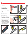 20
20
-
 21
21
-
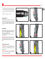 22
22
-
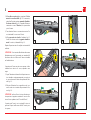 23
23
-
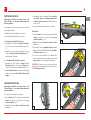 24
24
-
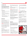 25
25
-
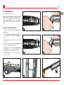 26
26
-
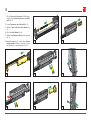 27
27
-
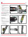 28
28
-
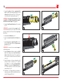 29
29
-
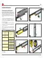 30
30
-
 31
31
-
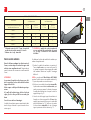 32
32
-
 33
33
-
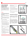 34
34
-
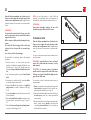 35
35
-
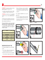 36
36
-
 37
37
-
 38
38
-
 39
39
-
 40
40
-
 41
41
-
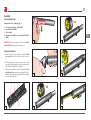 42
42
-
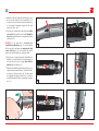 43
43
-
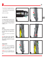 44
44
-
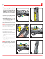 45
45
-
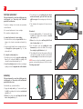 46
46
-
 47
47
-
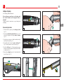 48
48
-
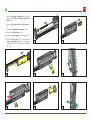 49
49
-
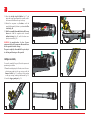 50
50
-
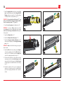 51
51
-
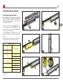 52
52
-
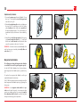 53
53
-
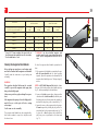 54
54
-
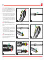 55
55
-
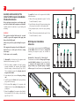 56
56
-
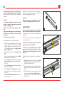 57
57
-
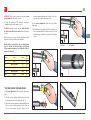 58
58
-
 59
59
-
 60
60
-
 61
61
-
 62
62
-
 63
63
-
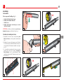 64
64
-
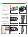 65
65
-
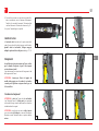 66
66
-
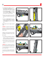 67
67
-
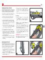 68
68
-
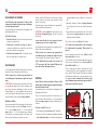 69
69
-
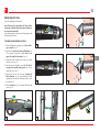 70
70
-
 71
71
-
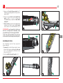 72
72
-
 73
73
-
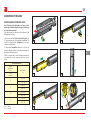 74
74
-
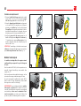 75
75
-
 76
76
-
 77
77
-
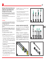 78
78
-
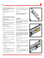 79
79
-
 80
80
-
 81
81
-
 82
82
-
 83
83
-
 84
84
-
 85
85
-
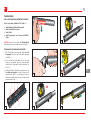 86
86
-
 87
87
-
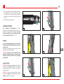 88
88
-
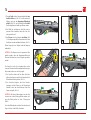 89
89
-
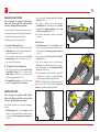 90
90
-
 91
91
-
 92
92
-
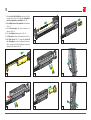 93
93
-
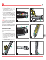 94
94
-
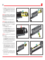 95
95
-
 96
96
-
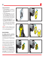 97
97
-
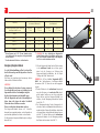 98
98
-
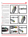 99
99
-
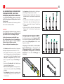 100
100
-
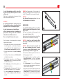 101
101
-
 102
102
-
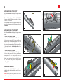 103
103
-
 104
104
-
 105
105
-
 106
106
-
 107
107
-
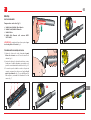 108
108
-
 109
109
-
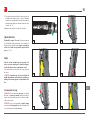 110
110
-
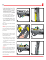 111
111
-
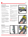 112
112
-
 113
113
-
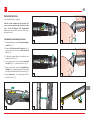 114
114
-
 115
115
-
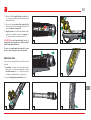 116
116
-
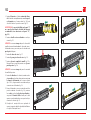 117
117
-
 118
118
-
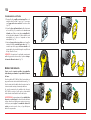 119
119
-
 120
120
-
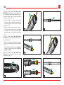 121
121
-
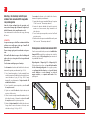 122
122
-
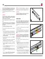 123
123
-
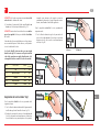 124
124
-
 125
125
-
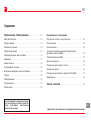 126
126
-
 127
127
-
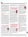 128
128
-
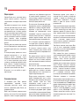 129
129
-
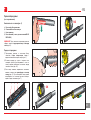 130
130
-
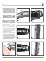 131
131
-
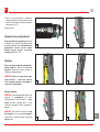 132
132
-
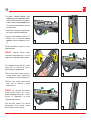 133
133
-
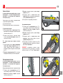 134
134
-
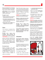 135
135
-
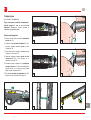 136
136
-
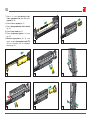 137
137
-
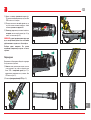 138
138
-
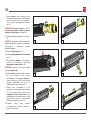 139
139
-
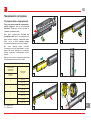 140
140
-
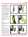 141
141
-
 142
142
-
 143
143
-
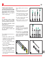 144
144
-
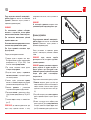 145
145
-
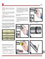 146
146
-
 147
147
-
 148
148
-
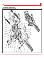 149
149
-
 150
150
-
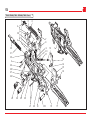 151
151
-
 152
152
-
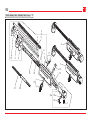 153
153
-
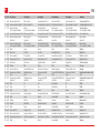 154
154
-
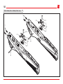 155
155
-
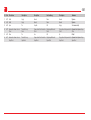 156
156
-
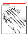 157
157
-
 158
158
-
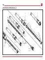 159
159
-
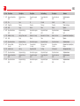 160
160
-
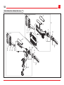 161
161
-
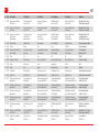 162
162
-
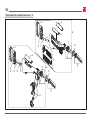 163
163
-
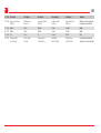 164
164
-
 165
165
-
 166
166


Benelli Super Vinci Black Use and Maintenance Manual
- Tipo
- Use and Maintenance Manual
en otros idiomas
- français: Benelli Super Vinci Black
- italiano: Benelli Super Vinci Black
- English: Benelli Super Vinci Black
- Deutsch: Benelli Super Vinci Black
- русский: Benelli Super Vinci Black
Artículos relacionados
-
Benelli Comfort 20 Use and Maintenance Manual
-
-
Benelli Argo E Comfortech Camo APG Use and Maintenance Manual
-
-
-
-
-
-
-
Otros documentos
-
Master Lock 99KADSPT Instrucciones de operación
-
-
-
Shimano BR-M515 Service Instructions
-
Walther PPK-S Manual de usuario
-
-
JT Splatmaster Z200 El manual del propietario
-
BoConcept Model 800 Assembly Instruction