Aprimatic ZT 71 Installation Instructions Manual
- Categoría
- Abridor de puerta
- Tipo
- Installation Instructions Manual
Este manual también es adecuado para

SISTEMA OLEODINAMICO
CANCELLI AD ANTA
BATTENTE CON
OPERATORE
OLEODINAMICO
INTRERRATO
Istruzioni per l'installazione
HYDRAULIC SYSTEM FOR
SWING-GATES WITH PUMP
UNIT AND UNDERGROUND
HYDRAULIC JACK
Installation instructions
SYSTEME
OLEODYNAMIQUE POUR
PORTAILS A VANTAIL
BATTANT AVEC
OPERATEUR
OLEODYNAMIQUE
ENTERRE
Instructions d’installation
ELEKTROHYDRAULISCHER
UNTERFLURDREHTORANTRIEB
Montageanleitung
SISTEMA OLEODINAMICO
PARA CANCELAS DE
PUERTA BATIENTE CON
OPERADOR
OLEODINAMICO
ENTERRADO
Instrucciones de instalación
Scopo del manuale
Questo manuale è stato redatto dal costruttore ed è parte integrante del prodotto.
Le informazioni in esso contenute sono direttte agli operatori esperti che eseguono l’ installazione e la manutenzione straordinaria.
Essi devono possedere competenze specifiche e particolari capacità per eseguire correttamente ed in sicurezza gli interventi di loro competenza. La costante osservanza
delle informazioni garantisce la sicurezza dell’uomo, l’economia di esercizio ed una piú lunga durata di funzionamento del prodotto. Al fine di evitare manovre errate con
il rischio di incidenti, è importante leggere attentamente questo manuale, rispettando scrupolosamente le informazioni fornite. Considerando che tale prodotto va installato
in abitazioni residenziali, l’operatore esperto, dopo aver effettuato l’intervento dovrá constatarne la corretta installazione ed il regolare funzionamento. Successivamente
dovrá istruire l’utente sull’uso corretto del prodotto rilasciando tutta la documentazione prevista dal costruttore.
L’indice descrittivo, posto all’inizio, consente facilmente la rintracciabilitá degli argomenti di interesse.
Purpose of the manual
This manual was drawn up by the manufacturer and is an integral part of the product.
The information it contains is addressed to expert operators that carry out the installation and maintenance operations.
They must have the specific qualifications and training to carry out this work correctly and under the maximum safety conditions.
Strict observance of the instructions contained in the manual will ensure safety, optimum operation and prolonged functioning of the product. To avoid incorrect
manoeuvres and therefore the risk of accidents, it is essential to read this manual with care and strictly follow all the instructions given. As this is a product to be installed
in residential buildings, the expert installer, after completing installation must verify that this has been performed correctly and that the product functions smoothly.
Subsequently, it is necessary to instruct the user on the correct use of the product providing all the documentation envisaged by the manufacturer.
The table of contents, at the beginning, makes it easy to find the topics of interest.
Objectif de la notice
Cette notice a été rédigée par le fabricant et fait partie intégrante du produit.
Les informations qui y sont contenues s’adressent aux opérateurs spécialisés qui effectuent les opérations d’installation et d’entretien extraordinaire.
Ceux-ci doivent posséder les compétences et les qualités requises pour effectuer de façon correcte et en toute sécurité les interventions dont ils sont chargés. La constante
observation de ces informations garantit la sécurité des personnes, une économie d’utilisation et une plus longue durée de vie du produit. Lire attentivement cette notice
et en respecter scrupuleusement les informations pour éviter toute fausse manoeuvre qui pourrait entraîner des accidents. Ce produit étant destiné aux habitations
résidentielles, après en avoir effectué la pose, l’opérateur devra en vérifier la bonne installation et le bon fonctionnement .
Il devra ensuite informer l’utilisateur de l’emploi correct du produit et lui remettre toute la documentation prévue par le fabricant.
Le sommaire détaillé, placé au début de la notice, permet de retrouver facilement les sujets à consulter.
Zweck der Montageanleitung
Das vorliegende Handbuch wurde vom Hersteller verfaßt und ist Bestandteil des Produkts.
Die darin enthaltenen Informationen richten sich an erfahrenes Personal, das sowohl die Installation als auch außerordentliche Wartungsarbeiten durchführt.
Dieses Personal muß über spezifische Fähigkeiten und Kompetenzen verfügen, um die Arbeit korrekt und unter sicheren Bedingungen durchführen zu können.
Die ständige Beachtung der Anweisungen gewährleistet Sicherheit, wirtchaftlichen Betrieb der Anlage und eine längere Lebensdauer des Produkts.
Zur Vermeidung von Fehlern, die zu Unfällen führen könnten, muß das vorliegende Handbuch aufmerksam durchgelesen und die darin enthaltenen Anweisungen genau
befolgt werden.
Da das Produkt im Privatwohnbereich installiert wird, muß das erfahrene Personal nach der Installation die korrekte Montage und den einwandfreien Betrieb überprüfen.
Anschließend muß es den Benutzer in den richtigen Gebrauch des Produkts einweisen und ihm die vom Hersteller vorgesehene Dokumentation aushändigen.
Das Inhaltsverzeichnis am Anfang des Handbuchs ermöglicht eine schnelle Ermittlung der jeweiligen Punkte.
Objetivo del manual
Este manual ha sido redactado por el constructor y forma parte integrante del producto. Las informaciones que contiene van dirigidas a los operadores especializados
encargados de las operaciones de instalación y mantenimiento extraordinario.
Dichos operadores deberán poseer la competencia especifica y las capacidades necesarias para llevar a efecto correctamente y en condiciones de seguridad las
operaciones de las que están encargados.
El cumplimiento constante de estas instrucciones garantiza seguridad del personal, economía de uso y un funcionamento más duradero del producto. A fin de evitar
maniobras incorrectas con el consiguiente riesgo de accidentes cabe leer con atención este manual y respetar escrupulosamente las instrucciones.
Puesto que el producto está destinado a la instalación en viviendas, el operador especializado, después de realizar la instalación, deberá comprobar la correcta ejecución
de la misma y el buen funciomento del producto.
También deberá enseñar al cliente cómo utilizar correctamente el producto, entregando toda la documentación facilitada por el constructor.
El índice descriptivo inicial permite encontrar con facilidad los temas que interesen.
PER UN CORRETTO MONTAGGIO LEGGERE ATTENTAMENTE LE ISTRUZIONI.
FOR A CORRECT ASSEMBLY, CAREFULLY READ THE FOLLOWING.
POUR UN ASSEMBLAGE CORRECT, LIRE ATTENTIVEMENT LES ISTRUCTIONS.
FÜR EINE KORREKTE INSTALLATION, DIESE ANLEITUNGEN SORGFÄLTING LESEN.
LEER ATENTAMENTE LAS INSTRUCCIONES PARA UN MONTAJE CORRECTO.
Cod.A1913000
ZT 71
ZT 72

GENERALITÁ /
GENERAL
/
GENERALITES /
ALLGEMEINES
/ GENERALIDAD
Dati tecnici
Technical data
Caractéristiques techniques
Technische Daten
Datos técnicos ....................................................................................................................................................................................................................... pag. 3
Caratteristiche generali
General features
Caracteristiques generales
Allgemeine merkmale
Caracteristicas generales .....................................................................................................................................................................................................
pag. 3
Dimensioni del complesso operatore oleodinamico interrato ZT 71 - ZT 72
Dimensions of the ZT 71 - ZT 72 underground hydraulic operator group
Dimensions du groupe actionneur hydraulique souterrain ZT 71 -ZT 72
Abmessungen des unterirdischen öldynamischen Antriebskomplexes ZT 71 – ZT 72
Dimensiones del grupo operador hidráulico enterrado ZT 71 - ZT 72 .............................................................................................................................
pag. 4
Specifica delle versioni dell’interrato ZT 71 - ZT 72
Specifications of the ZT 71 - ZT 72 underground versions
Spécifications des version du souterrain ZT 71 - ZT 72
Spezifikationen der Versionen des unterirdischen Komplexes ZT 71 – ZT 72
Especificaciones versiones enterrado ZT 71 -ZT 72 ..........................................................................................................................................................
pag. 5
CONTROLLI PRELIMINARI /
PRELIMINARY CHECKS / CONTROLES PREALABLES
VORKONTROLLEN / CONTROLES PREVIOS
Controlli preliminari
Preliminary checks
Contrôles préliminaires
Kontrollen vor der Montage
Controles previos ..................................................................................................................................................................................................................
pag. 6
Disposizione dei componenti (B2)
Arrangement of the components (B2)
Emplacement des elements constituant le systeme (B2)
Anordnung der bauteile (B2)
Distribucion de los componentes (B2) ................................................................................................................................................................................
pag. 7
Verifica componenti
Checking components
Verification generale
Nachprüfung der bestandteile
Verificacion componenetes ..................................................................................................................................................................................................
pag. 9
Elenco dei componenti operatore ZT 71 - ZT 72
Lst of the ZT 71 -ZT 72 operator components
Liste des cmposants de l’actionneur ZT 71 -ZT 72
Verzeichnis der Komponenten Trieb ZT 71 -ZT 72
Lista componentes operador ZT 71 -ZT 72..........................................................................................................................................................................
pag. 9
Preparazione al montaggio
Prepararion for installation
Preparation au montage
Vorbereitung zur montage
Preparacion a la instalacion .................................................................................................................................................................................................
pag. 11
ISTRUZIONI PER IL MONTAGGIO
/ INSTALLATION INSTRUCTIONS / NOTICES POUR LE MONTAGE
MONTAGESNLEITUNG / INSTRUCCIONES DE INSTALACCION
Cassetta di fondazione CIA 171
CIA 171 foundation box
Caisson de fondation CIA 171
Gründungskasten CIA 171
Cajón de fundación CIA 171 .................................................................................................................................................................................................
pag. 13
Installazione cassetta di fondazione CIA 171
Installation of the CIA 171 foundation box
Installation du caisson de fondation CIA 171
InstallationGründungskasten CIA 171
Instalación cajón de fundación CIA 171 ..............................................................................................................................................................................
pag. 14
Posizionamento della bussola
Positioning of the bush
Positionnement de la douille
Anbringung der Buchse
Colocación del casquillo .......................................................................................................................................................................................................
.pag. 15
1
INDICE
CONTENTS TABLE DES MATIERES INHALTSVERZEICHNIS INDICE
A
B
C

Installazione operatore ZT 71 (110°) ZT 72 (220°)
Installation of the ZT 71 (110°) ZT 72 (220°) operator
Installation de l’actionneur ZT 71 (110°) ZT 72 (220°)
Installation des Triebs ZT 71 (110°) ZT 72 (220°)
Instalacón del operador ZT 71 (110°) ZT 72 (220°) ..............................................................................................................................................................
pag. 16
Istruzioni per lo sfiato dell’apparecchiatura
Instructions to bleed the appliance
Instructions pour la purge du dispositif
Anleitung für die Entlüftung des Geräts
Instrucciones para la purga de aire del equipo ..................................................................................................................................................................
pag. 18
ATTIVAZIONE AUTOMAZIONE
/ ENABLING AUTOMATION / MISE EN SERVICE DE L’AUTOMATISATION
AKTIVIERUNG DES ANTRIEBS / ACTIVACION AUTOMATIZACION
Allacciamento elettrico
Electrical connections
Branchement electrique
Elektrischer anschluss
Conexion electrica .................................................................................................................................................................................................................
pag. 19
Regolazione delle pressioni e delle spinte
Adjustement of pressure and thrust
Reglage des pressions et des pousses
Einstellung von druck und schubkraft
Regulacion de las presiones y empoyes .............................................................................................................................................................................
pag. 21
Regolazione frenata in fase di apertura e chiusura
Adjustment of braking during opening and closing phases
Reglage du freinage lors de l’ouverture et de la frenature
Einstellung der abbremsung bei öffnungs-und schliessbewegung
Regulacion frenado en fase de apertura y cierre................................................................................................................................................................
pag. 22
Montaggio decentrato del martinetto
Off-center Jack fitting
Montage desaxe du verin
Versetzte drehzylindermontage
Instalacion de scentralizada del gato ..................................................................................................................................................................................
pag. 23
APPENDICE /
APPENDIX / NOTICE FINALES
ANLAGE / APENDICE
Guida ricerca guasti
Trouble -shooting
En cas de pannes
Fehlersuche
Guia de averias ......................................................................................................................................................................................................................
pag. 26
Istruzioni per l’utilizzatore
End user instruction
Instructions utilisateurs
Hinweise fur den benutzer
Instrucciones para el usuario ...............................................................................................................................................................................................
pag. 30
2
INDICE
CONTENTS TABLE DES MATIERES INHALTSVERZEICHNIS INDICE
D
E

- Il sistema, per l'azionamento di ogni singola anta, è composto da una centralina idraulica realizzata in differenti versioni di portata della pompa e da un
martinetto idraulico da incassare nel terreno in corrispondenza delle cerniere dell'anta del cancello.
- Il martinetto, prodotto in due versioni per l'apertura utile di 114° o 190°, dispone di un sistema regolabile per rallentare la velocità del cancello durante il suo
movimento nelle ultime fasi di apertura e di chiusura in modo da non fare sbattere il cancello sugli arresti; è costruito in struttura robusta da supportare ante
fino ad un peso di 800 Kg.
- La centralina idraulica è completa di valvole di regolazione della forza di apertura e chiusura così sensibili da garantire, una volta tarate in opera, la sicurezza
antischiacciamento; inoltre in tutte le versioni è prevista la valvola per lo sblocco di emergenza per il comando manuale del cancello.
- Le diverse versioni di blocco e portata pompa sono illustrate nella tabella dei dati tecnici.
- The system, for operating each single leaf, consists of an hydraulic pump unit produced with different pump capacity versions and an hydraulic jack to be buried
in the ground on which the gate hinges are aligned.
- The jack, produced in two versions for 114° or 190° opening, has an adjustable system to slow down the speed of the gate during the final opening and closing
stages of its movement to avoid banging the gate against its stops; it is built with a strong frame able to support leaves weighing up to a weight of 800 kg.
- The hydraulic pump unit is complete with opening and closing force adjustment valves that are calibrated in situ to guarantee the correct operation of the non-
crush safety device; furthermore all the versions have a built in emergency release valve for manual control of the gate.
CARATTERISTICHE GENERALI
ZT 71 ZT 72
temperatura di funzionamento
Working temperature
température de fonctionnement
Betriebstemperatur
temperatura de funcionamiento
peso con olio
Weight with oil (kg)
poids avec huile (Kg)
Gewicht mit Öl (Kg)
peso con aceite (kg)
olio tipo
Type of oil
type d’huile
Öltyp
tipo de aceite
45
-25° C / + 70° C
18
0,9 L
AprimOil HC13
DATI TECNICI
/ TECHNICAL DATA
DETAILS TECHNIQUES / TECHNISCHE DATEN
DATOS TECNICOS
pressione max. di esercizio (bar)
Max. working pressure (bar)
Pression maxi de service (bar)
Max. Betriebsdruck (bar)
presión máxima de ejercicio (bar)
tensione di alimentazione monofase
single-phase power supply
tension d’alimentation monophasée
Einphasige Betriebsspannung
tensión de alimentación monofásica
potenza assorbita (W)
Absorbed power (W)
puissance absorbée (W)
Aufnahmeleistung (W)
potencia absorbida (W)
3
A
DATI TECNICI TECHNICAL DATA CARACTERISTIQUES TECHNIQUES TECHISCHE DATEN DATOS TECNICOS
250
Quantità olio
Quantity of oil (l)
quantité d’huile (l)
Ölmenge (l)
cantidad aceite (l)
peso max. dell’anta da movimentare (Kg)
Max. weight of wing to be moved (kg)
poids max. du vantail à manoeuvrer (kg)
Max. Flügelgewicht (kg)
peso máx. de la puerta (kg)
velocità angolare con pompa da 0,75 lt./min.
Angular speed with 0.75 l/min pump
vitesse angulaire avec pompe de 0,75 l/min
Drehgeschwindigkeit mit Pumpe 0,75 l/min.
velocidad angular con bomba de 0,75 l/min.
velocità angolare con pompa da 0,6 lt./min.
Angular speed with 0.6 l/min pump
vitesse angulaire avec pompe de 0,6 l/min
Drehgeschwindigkeit mit Pumpe 0,6 l/min.
velocidad angular con bomba de 0,6 l/min.
max. angolo utile di lavoro
Max. working angle
angle utile de travail maximal
Max. Nutzöffnungswinkel
máx. ángulo útil de trabajo
angolo totale di rotazione
Total rotation angle
angle total de rotation
Gesamt-Öffnungswinkel
ángulo total de rotación
114°
190°
6°/sec
6°/sec
7°/sec
7°/sec
800
800
124°
200°
GENERAL FEATURES
250
230 V±10%50÷60 Hz 230 V±10%50÷60 Hz
45
-25° C / + 70° C
19,4
0,95 L
AprimOil HC13
portata pompa (lt./min.)
Pump capacity (l/min)
débit de pompe (l/min)
Pumpenfördermenge (l/min)
caudal bomba (L/min)
0,6 0,75 0,6 0,75
B4 B5 SF4 SF5
ZT 71 ZT 72

4
A
TIPOLOGIA DI BASCULANTI NON AUTOMATIZZABILI CON OPERATORE SERIE EM 51
- The different block and pump capacity versions are illustrated in the technical data table.
- Le système, pour l’entraînement de chaque vantail, se compose d’une centrale hydraulique réalisée en plusieurs versions selon le débit de pompe et d’un vérin
hydraulique à encastrer dans le sol à l'aplomb des gonds du vantail du portail.
- Le vérin, fabriqué en deux versions pour l’ouverture utile de 114° ou 190°, dispose d’un système réglable permettant de ralentir la vitesse du portail en fin
d’ouverture et de fermeture, l’empêchant ainsi de claquer sur les butées; la structure est en construction robuste pouvant supporter un vantail pesant jusqu’à
800 Kg.
- La centrale hydraulique est équipée de soupapes de réglage de la force d’ouverture et de fermeture d’une grande sensibilité assurant, une fois réglées lors
de la mise en oeuvre, la sécurité anti-écrasement; de plus, toutes les versions prévoient un bouton pour le déverrouillage d’urgence permettant la commande
manuelle du portail.
- Les différentes versions à blocage et de débit de pompe figurent au tableau des détails techniques.
- Das System zum Antrieb jedes einzelnen Flügels besteht aus einem Hydraulikaggregat, das in verschiedenen Ausführungen mit unterschiedlicher
Pumpenfördermenge angeboten wird, sowie aus einem Antriebszylinder, der in den Boden einzulassen ist, an dem die Scharniere der Torflügel angebracht
sind.
- Der Drehzylinder, hergestellt in zwei Versionen mit verschiedenen Nutz Öffnungswinkeln von 114° und 190°, verfügt über ein regulierbares System zur
Abbremsung der Geschwindigkeit im letzten Teil der Öffnungs- und Schließbewegung, so daß das Tor nicht heftig gegen die Anschläge stößt; er besteht aus
einer robusten Struktur, ist für ein Torflügelgewicht bis 800 kg.
- Das Hydraulikaggregat ist mit Ventilen zur Einstellung der Öffnungs- und Verschlußkraft versehen. Diese Ventile werden nach der Installation eingestellt und
garantieren für den Quetschschutz, außerdem ist in allen Ausführungen ein Ventil für die manuelle Not-Entriegelung des Tors vorgesehen.
- Die verschiedenen Ausführungen mit unterschiedlichen Blockierungen und Pumpenfördermengen werden in der Tabelle Technische Daten dargestellt.
- El sistema, para el accionamiento de cada puerta batiente, consta de una centralita hidráulica fabricada en diferentes versiones de caudal de bomba y de
un gato hidráulico a encajar en el suelo en correspondencia con las bisagras de la puerta.
- El gato, fabricado en dos versiones para una apertura útil de 114° o 190°, cuenta con un sistema regulable para disminuir la velocidad de la puerta durante
su movimiento en las últimas fases de apertura y cierre para que esta no golpee bruscamente en los topes. Su estructura es robusta y capaz de soportar puertas
hasta un peso de 800 kg.
- La centralita hidráulica se provista de válvulas de regulación de la fuerza de apertura y cierre tan sensibles que pueden garantizar, una vez calibradas en
obra, la seguridad anti-aplastamiento. Además, en todas las versiones se ha previsto la válvula para el desbloqueo de emergencia para mover manualmente
la puerta.
- Las diferentes versiones de bloqueo y caudal se ilustran en el cuadro de los datos técnicos.
CARACTERISTIQUES GENERALES
ALLGEMEINE MERKMALE
A1
CARACTERISTICAS GENERALES
DIMENSIONI DEL COMPLESSO OPERATORE OLEODINAMICO INTERRATO ZT 71 - ZT 72
DIMENSIONS OF THE ZT 71 - ZT 72 UNDERGROUND HYDRAULIC OPERATOR GROUP
DIMENSIONS DU GROUPE ACTIONNEUR HYDRAULIQUE SOUTERRAIN ZT 71 -ZT 72
ABMESSUNGEN DES UNTERIRDISCHEN ÖLDYNAMISCHEN ANTRIEBSKOMPLEXES ZT 71 – ZT 72
DIMENSIONES DEL GRUPO OPERADOR HIDRÁULICO ENTERRADO ZT 71 - ZT 72
B
A
CB
B
A
E
A
D
C
A (mm)
B (mm)
C (mm)
D (mm)
MODELLO ZT 71 ZT 72
290
151
140
45
355
151
140
45
E (mm)
20,5 45
A (mm)
B (mm)
270,5
380,5
CASSETTA CIA 171

SPECIFICA DELLE VERSIONI DELL’INTERRATO ZT 71 -ZT 72
5
A
B Modello con Doppio Blocco idraulico in apertura e chiusura. L'uso di questa versione è limitata sia dal peso dell'anta che dalla sua lunghezza. Viene prodotto in due versioni:
B4 .........velocità bassa.....................Peso max. anta 800 Kg. ...................................Lunghezza Max. anta 2,0 mt.
B5 .........velocità alta ........................Peso max. anta 400 Kg. ................................... Lunghezza Max. anta 1,7 mt.
SF Senza Blocco Idraulico-Frenato; con questo modello l'anta è movimentabile a mano con una leggera resistenza al moto.
Il modello S necessita di ELETTROSERRATURA ed
è prodotto in due versioni a seconda del peso e della lunghezza dell'anta:
SF4 ...... velocità bassa .....................Peso max. anta 800 Kg. ...................................Lunghezza Max. anta 4,0 mt.
C Blocco idraulico solo in chiusura (fornibile solo a richiesta). L'utilizzo di questo modello è limitato dal peso e dalla lunghezza dell'anta come per il modello B.
ATTENZIONE
La scelta del modello da utilizzare dipende non solo dal peso e dalla lunghezza dell'anta, ma anche dalle caratteristiche applicative dell'automazione e dallo stato dell'anta
da muovere (vedi paragrafo CONTROLLI PRELIMINARI e VERIFICA SCELTA AUTOMAZIONE).
B Model with double hydraulic lock on opening and closing. The use of this version depends on the weight of the gate and its length. It is produced in two versions:
B4 ......... low speed ..........................Max. leaf weight 800 kg................................................ Max leaf length 2.0 m
B5 ......... high speed .........................Max. leaf weight 400 kg................................................Max leaf length 1.7 m
SF Without Hydraulic Lock; with this model the gate can be moved by hand with a slight pressure.
The S model requires an ELECTRIC LOCK and is produced in two versions for
different gate weights and lengths:
SF4 ...... low speed ...........................Max. leaf weight 800 kg................................................ Max leaf length 4.0 m
C Hydraulic lock only on closing (supplied only on request). The use of this model depends on the weight and length of the gate as for model B.
ATTENTION
The choice of model to be used does not just depend of the weight and length of the gate, but also on the working features of the automatic device and the condition of
the gate to be moved (see paragraph on PRELIMINARY CONTROLS and CORRECT AUTOMATION SELECTION)
B Modèle avec double verrouillage hydraulique en ouverture et fermeture. L’emploi de cette version est limitée aussi bien par le poids du vantail que par sa largeur. Il est fabriqué
en deux versions:
B4 .........petite vitesse .............. Poids maxi du vantail 800 Kg ................... largeur maxi du vantail 2,0 m
B5 .........vitesse élevée............. Poids maxi du vantail 400 Kg ................... largeur maxi du vantail 1,7 m
SF Sans Verrouillage Hydraulique-Freiné; avec ce modèle le vantail peut être manoeuvré à la main avec une légère résistance au mouvement.
Le modèle S exige une
ELECTROSERRURE et est fabriqué en deux versions selon le poids et la largeur du vantail:
SF4 ...... petite vitesse .............. Poids maxi du vantail 800 Kg ................... largeur maxi du vantail 4,0 m
C Verrouillage hydraulique en fermeture seulement (ne peut être fourni que sur demande). L’emploi de ce modèle est limité par le poids et par la largeur du vantail, comme pour le
modèle B.
ATTENTION
Le choix du modèle à utiliser dépend non seulement du poids et de la largeur du vantail, mais aussi des caractéristiques d’application de l’automatisation et de l’état du
vantail à manoeuvrer (voir paragraphe des CONTRÔLES PRÉLIMINAIRES et VÉRIFICATION DU CHOIX DE L’AUTOMATISATION).
B Modell mit doppelter Hydraulikblockierung beim Öffnen und Schliessen. Die Einsatzmöglichkeiten dieser Ausführung werden sowohl vom Gewicht des Torflügels als auch von
dessen Länge begrenzt. Hergestellt werden zwei Ausführungen:
B4 ......geringe Geschwindigkeit ........... max. Torflügel-Gewicht 800 kg ...................... max. Torflügel-Länge 2,0 m
B5 ......hohe Geschwindigkeit ............... max. Torflügel-Gewicht 400 kg ...................... max. Torflügel-Länge 1,7 m
SF Ohne hydraulische Blockierung/Bremse: bei diesem Modell kann der Torflügel mit geringfügigem Widerstand von Hand bewegt werden.
Das Modell S erfordert den Einbau von
einem ELEKTROSCHLOSS und wird je nach Gewicht und Länge des Torflügels in 2 Ausführungen angeboten:
SF4 ....geringe Geschwindigkeit ........... max. Torflügel-Gewicht 800 kg ...................... max. Torflügel-Länge 4,0 m
C Hydraulikblockierung nur bei geschlossenem Tor (nur auf Anfrage lieferbar). Die Einsatzmöglichkeiten dieser Ausführung werden wie bei Modell B vom Gewicht und der Länge
des Torflügels begrenzt.
ACHTUNG
Die Wahl des richtigen Modells hängt nicht nur vom Gewicht und von der Länge des Torflügels ab, sondern auch von der vorgesehenen Einbauart des Antriebs und vom
Zustand des Torflügels ab (siehe Paragraph “Vorkontrolle und Nachprüfung der Antriebswahl”)
B Modelo con Doble Bloqueo Hidráulico en apertura y cierre. El uso de esta versión está limitado por el peso de la puerta y su largo. Se fabrica en dos versiones :
B4 .........velocidad baja ....................Peso máx. puerta 800 Kg........................................ Largo máx. puerta 2.0 m
B5 .........velocidad alta .....................Peso máx. puerta 400 Kg........................................ Largo máx. puerta 1,7 m
SF Sin Bloqueo hidráulico frenado; con este modelo se hace el movimiento manual de la puerta superando una ligera resistencia al movimiento.
El modelo S precisa de la
electrocerradura y se fabrica en dos versiones de acuerdo con el peso y el largo de la puerta :
SF4 ...... velocidad baja ....................Peso máx. puerta 800 Kg........................................ Largo máx. puerta 4,0 m
C Bloqueo hidráulico sólo durante el cierre ( sólo bajo pedido). El uso de este modelo está limitado por el peso y el largo de la puerta como en el caso del modelo B.
ATENCION
La elección del modelo depende no sólo del peso y del largo de la puerta, sino también de las características de aplicación de la automatización y de la situación de la
puerta a mover ( véase párrafo controles previos y verificación opciones de automatización)
SPECIFICATIONS OF THE ZT 71 - ZT 72 UNDERGROUND VERSIONS
SPÉCIFICATIONS DES VERSION DU SOUTERRAIN ZT 71 - ZT 72
SPEZIFIKATIONEN DER VERSIONEN DES UNTERIRDISCHEN KOMPLEXES ZT 71 –ZT 72
ESPECIFICACIONES VERSIONES ENTERRADO ZT 71 - ZT 72

6
B
CONTROLLI PRELIMINARI
Prima di eseguire il lavoro di installazione occorre verificare le condizioni del cancello da automatizzare:
- La costruzione meccanica deve essere robusta e rigida.
- Le cerniere non devono avere giochi o forti attriti e devono essere adeguate al peso dell'anta.
- Verificare che l'anta sia perfettamente a piombo.
- Verificare che non vi siano cedimenti del pilastro o delle cerniere fissate allo stesso.
ATTENZIONE
• Nel caso si rilevino anomalie occorre procedere al ripristino delle buone condizioni di funzionamento dell'anta prima di procedere all'installazione; è bene tenere
presente che ogni anomalia geometrica o strutturale del cancello potrebbe causare, nel tempo, pericolosi sovraccarichi sul martinetto.
• Se non sono presenti, è obbligatorio prevedere gli arresti a terra (B1 ➀) delle ante, sia in apertura che in chiusura, in modo da non superare mai l'angolo utile di lavoro
del martinetto indicato in figura B1. È consigliabile posizionare gli arresti a terra prima di effettuare l'installazione.
Before going ahead with installation first check the condition of the gate to be automated:
- The mechanical construction must be strong and stiff
- The hinges must not have any play or strong friction and must be adequate for the weight of the gate.
- Check that the gate hinges are perfectly perpendicular (at plumb).
- Check that the gate-post and the hinges fixed to it are secure.
ATTENTION
• If any faults are detected, the gate must be restored to good working order before installing the automatic device; it should be remembered that any geometric or
structural fault on the gate can, in time, cause dangerous overloading of the jack.
• Where they are not already present it is essential to fit ground stops (B1
➀
) for the open and the closed leaf so that it never goes beyond the working angle of the jack,
indicated in figure B1. It is advisable to position the ground stops before installation.
Avant d’effectuer le travail d’installation, vérifier l’état du portail à automatiser:
- La construction mécanique doit être robuste et rigide.
- Les charnières doivent être sans jeu ni frottement et doivent être appropriées au poids du vantail.
- Vérifier que le vantail
soit parfaitement d’aplomb.
- Vérifier que le pilier ou les gonds qui y sont fixés ne cèdent pas.
ATTENTION
• Si vous remarquez des anomalies, il faut rétablir les bonnes conditions de fonctionnement du vantail avant d’effectuer l’installation; il convient de se rappeler que toute
anomalie géométrique ou structurale du portail pourrait causer, dans le temps, de dangereuses surcharges sur le vérin.
• Si cela n’a pas encore été fait, il est impératif de prévoir des butées (B1
➀
) du vantail au sol aussi bien en ouverture qu’en fermeture afin de ne jamais dépasser l’angle
utile de travail du vérin indiqué à la figure B1. Nous conseillons de placer les butées au sol avant d’effectuer l’installation.
Vor Installation sollte der Zustand des zu automatisierenden Tors geprüft werden:
- Die Torkonstruktion sollte robust und starr sein.
- Die Scharniere dürfen kein Spiel oder starke Reibung aufweisen und müssen das Torflügelgewicht problemlos tragen.
- Kontrollieren, ob der Torflügel
perfekt im Lot ist.
- Sicherstellen, daß der Pfosten oder die daran befestigten Scharniere nicht verbogen oder verformt sind.
ACHTUNG
• Sollten Mängel am Tor festgestellt werden, dann sind diese vor Installation des Antriebs zu beseitigen. Jeder geometrische oder strukturelle Mangel des Tor kann im
Laufe der Zeit zu gefährlicher Überlastung des Drehzylinders führen.
• Falls nicht vorhanden, müssen am Boden Endanschläge angebracht werden (B1
➀
) sowohl für die völlige Öffnung als auch das Schliessen des Tors, so daß der in
Abbildung B1 angegebene Nutzarbeitswinkel des Drehzylinders nie überschritten wird. Es empfiehlt sich, die Bodenanschläge vor der Installation anzubringen.
Antes de realizar el trabajo de instalación hace falta verificar las condiciones de la cancela por automatizar :
- La construcción mecánica debe ser robusta y rígida
- Las bisagras no deben tener juegos o fuertes roces y deben adaptarse al peso de la puerta.
- Asegurarse que la puerta
esté a plomo.
- Comprobar que no haya hundimiento del pilar o de las bisagras sujetadas al mismo
ATENCION
• Si se detectan anomalías hace falta restablecer las buenas condiciones de funcionamiento de la puerta antes de realizar la instalación. Es importante considerar que
cualquier anomalía geométrica y de estructura de la cancela podría ocasionar, con el tiempo, sobrecargas en el gato.
• Si no están, es obligatorio prever los topes de parada al suelo (B1
➀
) de las puertas tanto en apertura como en cierre para no rebasar nunca el ángulo de trabajo del
gato (cf figura B1). Les aconsejamos que posicionen los topes al suelo antes de realizar la instalación.
PRELIMINARY CHECKS
CONTROLES PREALABLES
VORKONTROLLEN
CONTROLES PREVIOS
B 1

DISPOSIZIONE DEI COMPONENTI (B2)
A- Lampeggiatore Aprimatic (posizionare in un punto ben visibile da entrambi i lati del transito)
B- Fotocellula di sicurezza Aprimatic
C- Dispositivo di comando manuale a chiave (magnetica, digitale, combinatore a tastiera, meccanica, ecc.)
D- Apparecchiatura di comando Aprimatic a microprocessore in contenitore stagno (posizionare, possibilmente, al riparo da agenti atmosferici) (vedere listino)
E- Radio ricevente telecomando Aprimatic (possibilità di inserimento all'interno del lampeggiatore) (modello RG/RR - vedere listino)
F- Condotta per cavo di alimentazione della centralina idraulica proveniente dalla apparecchiatura elettrica
G- Antenna (optional)
H- ZT 71 - ZT 72 incassati ai piedi dei pilastri
I-Arresto meccanico in apertura e chiusura
L- Messa a terra delle strutture metalliche
M- Scatola di derivazione per impianto elettrico.
N.B.: Per ulteriori dispositivi di sicurezza (optional) consultare il listino prezzi.
ARRANGEMENT OF THE COMPONENTS (B2)
EMPLACEMENT DES ELEMENTS CONSTITUANT LE SYSTEME (B2)
A- Aprimatic flashing light (place in a point clearly visible when approaching the gate on either side)
B- Aprimatic safety photocell
C- Manual key control (magnetic, digital, key-pad, mechanical, etc.)
D- Aprimatic microprocessor control unit in sealed box (position, were possible, so that it is protected against the atmospheric agents) ( see price list)
E- Aprimatic remote control receiver (can be fitted inside the flashing lamp) (model RG/RR)
F- Tube for hydraulic control unit power supply cable coming from the control unit.
G- Antenna (optional)
H- ZT 71 - ZT 72 embedded in the pillar feet
I-Mechanical stop for opening and closing
L -Earth for the metal structures
M -Branch box for electrical system
N.B. For other safety devices (optional) please refer to the catalogue or price list.
A- Lampe clignotante Aprimatic (placer à un endroit bien visible des deux côtés du passage)
B- Photocellule de sécurité Aprimatic
C- Dispositif de commande manuelle à clé (magnétique, digitale, clavier à combinaison, mécanique, etc.)
D- Armoire de commande Aprimatic à microprocesseur en boîtier étanche (l’installer, si possible, à l’abri des agents atmosphériques) ( voir tarif)
E- Radio récepteur avec télécommande Aprimatic (pouvant être installé à l’intérieur de la lampe clignotante) (model RG/RR - voiv tarit)
F- Conduite pour le câble d’alimentation de la centrale hydraulique provenant de l’armoire électrique
G- Antenne (en option)
H
-
ZT 71 - ZT 72 encaissés aux pieds des piliers
I- Butée mécanique en ouverture et fermeture
L- Mise à la terre des structures métalliques
M - Boîtier de dérivation pour installation électrique
N.B. Si vous désirez des dispositifs de sécurité supplémentaires (en option), consulter le tarif.
7
B

A- Blinkmelder Aprimatic (an von beiden Torseiten aus gut sichtbarer Stelle anbringen)
B- Sicherheitslichtschranke Aprimatic
C- Vorrichtung zur manuellen Bedienung mit Schlüssel (Magnetkarte, Digitaleinrichtung, Tastatur, Mechanischer Schlüssel, usw.)
D- Mikroprozessor-Steuerung Aprimatic in wasserdichtem Gehäuse (möglichst an witterungsgeschützter Stelle installieren) (siehe Preisliste)
E- Funkempfänger mit Fernbedienung Aprimatic (mögliche Installation im Blinkmelder) (Modell RG/RR - siehe Preisliste)
F- Leitung für Versorgungskabel von der elektrischen Anlage an das Hydraulikaggregat
G- Antenne (Sonderzubehör)
H
-
ZT 71 – ZT 72 in die Pfeilerfüße eingelassen
I-Mechanischer Anschlag bei Öffnung und Schließvorgang
L- Erdung der Metallkonstruktionen
M-
Abzweigdose für Elektroanlage
Wichtig: Für weitere Sicherheitseinrichtungen (Sonderzubehör) siehe Preisliste.
A- Destellador Aprimatic (posicionar en un punto perfectamente visible de ambos lados del tránsito)
B- Célula fotoeléctrica de seguridad Aprimatic
C- Dispositivo de mando manual a llave ( magnética, digital, combinador de teclado, mecánica, etc.)
D- Cuadro de maniobras Aprimatic con microprocesador en caja estanca (colocar, si es posible el cuadro fuera del alcance de los agentes externos) (véaselista)
E- Radio receptor mando a distancia Aprimatic (posibilidad de inserción en el destellador) (modelo RG/RR - véase lista)
F- Canalizacion para cable de alimentación de la centralita hidráulica procedente del equipo eléctrico
G- Antena ( opcional)
H-
ZT 71 - ZT 72 enterrados a los pies de los pilotes
I-Tope mecánico en apertura y cierre
L- Puesta a la tierra de las estructuras metálicas
M-
Caja de derivación para instalación eléctrica
N.B. : Para otros dispositivos de seguridad (opcionales) consultar la lista de precios.
ANORDNUNG DER BAUTEILE (B2)
DISTRIBUCION DE LOS COMPONENTES (B2)
B 2
8
B

9
Prima di effettuare il montaggio è necessario verificare la scelta dell’automazione in funzione delle
caratteristiche e delle dimensioni dell’elemento da movimentare, dal modo di utilizzo dell’automazione e
dalle caratteristiche ambientali. L’esperienza è il migliore aiuto in questi casi, tuttavia consigliamo di seguire
alcuni criteri (B3).
Before beginning assembly, check that the packaging contains all the components listed below and that
these are not damaged. Check also that the model serial number on the packing case corresponds to the
one on the plaque (B3).
Avant de commencer le montage, contrôler que l’emballage contienne toutes les pièces énumérées ci-
après et qu’elles ne soient pas endommagées. Vérifier également que la référence du modèle indiqué sur
la boîte d’emballage correspond à celle figurant sur la plaquette de l’article (B3).
Vor Beginn mit der Montage sollte kontrolliert werden, ob in der Verpackung alle Bestandteile enthalten sind, die
nachfolgend aufgelistet werden. Die Teile dürfen nicht beschädigt sein. Außerdem kontrollieren, ob die Modell-
Kennummer auf der Verpackung mit der Kennummer auf dem Schild des Antriebs übereinstimmt (B3).
Antes de empezar el montaje controlar que el embalaje contenga todos los componentes listados a
continuación y que los mismos no estén estropeados. Asegurarse asimismo que la sigla del modelo
indicado en la caja del embalaje corresponda a la indicada en la plaquita del producto (B3).
B
VERIFICA COMPONENTI
CHECKING COMPONENTS
VERIFICATION GENERALE
NACHPRÜFUNG DER BESTANDTEILE
VERIFICACION COMPONENTES
B 3
CENTRALINA-MARTINETTO
CONTROL UNIT-CYLINDER
CENTRALE-VÉRIN
STEUEREINHEIT-ZYLINDER
CENTRALITA-CILINDRO
ELENCO DEI COMPONENTI OPERATORE ZT 71 - ZT 72
* CASSETTA CIA 171 (B5)
Pos. Descrizione
1 Coperchio cassetta Qt.1
2 Tappi plstica nera Qt.2
3 Viti TE 6x14 + rosette Qt.2
4 Attacco scanalato Qt.1
5 Boccola sinterizzata Qt.1
6 Viti TE 10x25 + dadi ES.M10 Qt.2
7 Dima per messa in fase martinetto Qt.1
* Venduta separatamente - Vedere listino
CENTRALINA-MARTINETTO (B4)
Pos. Descrizione
1 Centralina ZT 70 Qt.1
2 Marinetto ZT 71 o ZT 72 Qt.1
3 Valvola di sfiato Qt.1
4 Chiave triangolare Qt.1
5 Viti sollevamento martinetto TCCE 12x40 Qt.4
6 Condendatore 8 microF 400V 15 cm Qt.1
CONTROL UNIT - CYLINDER (B4)
Pos. Description
1 ZT 70 control unit 1 pc.
2 ZT 71 - ZT 72 cylinder 1 pc.
3 Air vent 1 pc.
4 Triangular key 1 pc.
5 Cylinder lifting Allen screws 12x40 4 pcs.
6 8 microF 400V 15 cm. capacitor 1 pc.
* CIA 171 BOX (B5)
Pos. Description
1 Box cover 1 pc.
2 Black plastic plugs 2 pcs.
3 Hexagon head cap screws 6x14 + washers 2 pcs.
4 Grooved attachment 1 pc.
5 Sintered bush 1 pc.
6 Hexagon head cap screws 10x25 +
+ hexagon nuts M10 2 pcs.
7 Template for cylinder phase adjustment 1 pc.
* Sold separately - See price-list
CENTRALE - VÉRIN (B4)
Pos. Désignation
1 Centrale ZT 70 Q.té 1
2 Vérin ZT 71- ZT 72 Q.té 1
3 Soupape de purge Q.té 1
4 Clé triangulaire Q.té 1
5 Vis de levage vérin à six pans creux 12x40 Q.té 4
6 Condensaateur 8 microF 400V 15 cm. Q.té 1
* BOÎTIER CIA 171 (B5)
Pos. Désignation
1
Couvercle boîtier
Q.té 1
2 Bouchons en plastique noire Q.té 2
3 Vis à tête hexagonale 6x14 + rondelles Q.té 2
4 Connexion rainée Q.té 1
5 Douille frittée Q.té 1
6 Vis à tête hexagonale 10x25 +
+ écrous hexagonaux Q.té 2
7 Gabarit pour mise en phase vérin Q.té 1
* Vendue separement - Voir tarif
F
ON
LiST OF THE ZT 71 - ZT 72 OPERATOR COMPONENTS
LISTE DES COMPOSANTS DE L’ACTIONNEUR ZT 71 - ZT 72

10
B
STEUEREINHEIT - ZYLINDER (B4)
Pos. Bezeichnung
1 Steuereinheit ZT 70 1.St
2 Zylinder ZT 71 - ZT 72 1.St
3 Entlüftungsventil 1.St
4 Dreiecksschlüssel 1.St
5 Hubschrauben Zylinder Innensechskant 12x40 4.St
6 Kondensator 8 microF 400V 15cm. 1.St
* KASTEN CIA 171 (B5)
Pos. Bezeichnung
1 Kastendeckel 1.St
2 Plastikvershlüssel 2.St
3 Sechskantschrauben 6x14 + Scheiben 2.St
4 Nutanschluss 1.St
5 Gesinterte Buchse 1.St
6 Sechskantschrauben 10x25 +
+ Sechskantmuttern 2.St
7 Schablone für Phaseneinstellung Zylinder 1.St
* Einzeln verkauft - Siehe Preisliste
CENTRALITA - CILINDRO (B4)
Pos. Descripción
1 Centralita ZT 70 Cdad.1
2 Cilindro ZT 71 - ZT 72 Cdad.1
3 Válvula de purga de aire Cdad.1
4 Llave triangular Cdad.1
5 Tornillos de cabeza cilíndrica con hexágono
interior para levantamiento cilindro 12x40 Cdad.4
6 Condensador 8 microF 400V 15cm. Cdad.1
* CAJA CIA 171 (B5)
Pos. Descripción
1 Tapadera caja Cdad.1
2 Tapones de plástico negro Cdad.2
3 Tornillos de cabeza hexagonal 6x14 +
+ tuercas hexagonales M10 Cdad.2
4 Empalme ranurado Cdad.1
5 Casquillo sinterizado Cdad.1
6 Tornillos de cabeza hexagonal 10x25 +
+ tuercas hexagonales M10 Cdad.2
7 Plantilla para regulación cilindro Cdad.1
B 4
B 5
1
2
7
4
5
2
1
3
3
1
2
7
6
5
VERZEICHNIS DER KOMPONENTEN TRIEB ZT 71 - ZT 72
LISTA COMPONENTES OPERADOR ZT 71 - ZT 72
* Vendida separadamente - Ver lista de precios
5
3
6
4

11
B
Il montaggio dell’operatore richiede una serie di lavori di preparazione del cancello da movimentare da eseguirsi, se il cancello è già installato, direttamente sul
luogo dell'installazione; è quindi necessario premunirsi dell'attrezzatura adatta che consenta all'installatore la massima autonomia durante il lavoro.
AVVERTENZA
L'elenco dell'utensileria necessaria, è riportato nella figura, comprensiva di tabella, (B 6).
PREPARAZIONE AL MONTAGGIO
l Livella a bolla (tridimensionale)
l Grasso tipo grafitato.
l Olio tipo AprimOil HC 13 (olio espressamente formulato per Aprimatic)
l Bomboletta Zincospray
l Vernice antiruggine
l Pennelli per verniciatura
l Diluente per pulizia pennelli
l Spazzola metallica
l Lime varie
l Punte da tracciatura
l Martello
l Scalpello per acciaio e per muratura
l Salviette detergenti
l Carta per asciugatura mani
l Cassetta "Pronto soccorso"
ATTREZZATURA BASE E MATERIALE DI CONSUMO OCCORRENTE
l Occhiali di protezione
l Maschera di protezione
l Saldatore da stagno
l Trapano elettrico di potenza adeguata alimentazione 220 V.
l Punte da trapano
l Fresa a tazza ø 67 per fori alloggiamento fotocellule e pulsantiere
l Cavo di prolunga per attrezzatura elettrica
l Cavo elettrico sez. 1,5 mm
2
vari colori + capicorda vario tipo
l Forbici da elettricista
l Pinze per capicorda
l Tester
l Calibro ventesimale
l Metro
l Goniometro
l Dinamometro
The installation of the pump unit requires a series of preparatory operations on the gate to be automated, if the gate is already installed, at the installation site;
it is therefore necessary to prepare the equipment that will give the installer maximum autonomy.
WARNING
The list of tools necessary is given in the figure, including the table, (B 6)
PREPARARION FOR INSTALLATION
l
Dynamometer
l
Plumb line
l
Spirit level (three-dimensional)
l
Graphite type grease
l
AprimOil HC 13 type oil (oil specially formulated for Aprimatic)
l
Zincospray canister
l
Rust inhibitor paint
l
Pain brushes
l
Metal brush
l
Various files
l
Iron saws
l
Marking bits
l
Hammer
l
Metal and masonry chisels
l
Wipe clean tissues
l
Paper towels
l
First Aid box
BASIC EQUIPMENT AND DISPOSABLE MATERIAL REQUIRED
l
Protective goggles
l
Protective mask
l
Soft soldering iron
l
Electric drill: 220V
l
Drill bits
l
Cup milling cutter dia. 67 for photocell and push-button sheet-panel
housings
l
Extension cable for electrical equipment
l
Electric cable 1.5 mm
2
in various colours + various types of cable terminals
l
Electrician’s scissors
l
Cable terminal grippers
l
Tester
l
Calliper in twentieths
l
Measuring stick
PREPARATION AU MONTAGE
Le montage de l’opérateur exige une série de travaux pour préparer le portail à manoeuvrer qui doivent être effectués, si le portail est déjà installé, directement
sur le lieu d’installation.; il est donc nécessaire de prévoir l’équipement adéquat qui donnera le maximum d’autonomie à l’installateur effectuant le travail.
AVERTISSEMENT
La liste de l’outillage nécessaire est indiquée sur la figure avec tableau (B 6).
EQUIPEMENT DE BASE ET MATÉRIEL DE CONSOMMATION NÉCESSAIRE
l
Lunettes de protection
l
Masque de protection
l
Fer à souder pour étain
l
Perceuse électrique avec puissance adéquate alimentation: 220V
l
Forets de perceuse
l
Fraise ø 67 pour trous de logement des photocellules et boutons-poussoirs
l
Câble de rallonge pour équipement électrique
l
Câble électrique sec. 1,5 mm
2
plusieurs couleurs + cosses de différents
types
l
Ciseaux d’électricien
l
Pinces à cosses
l
Testeur
l
Pied à coulisse vingtésimal
l
Mètre
l
Rapporteur
l
Fil à plomb
l
Niveau à bulle (tridimensionnel)
l
Graisse du type graphitée
l
Huile type AprimOil HC 13
(huile formulée expressément pour Aprimatic)
l
Zinc spray
l
Peinture anti-rouille
l
Pinceaux pour peindre
l
Diluant pour nettoyer les pinceaux
l
Brosse métallique
l
Assortiment de limes
l
Pointes de traçage
l
Marteau
l
Ciseau pour acier et maçonnerie
l
Serviettes détergentes
l
Papier essuie-mains
l
Boîte de secours

12
B
VORBEREITUNG ZUR MONTAGE
Zur Montage des Antriebs sind eine Reihe vorbereitender Maßnahmen am Tor erforderlich. Bei schon installiertem Tor erfolgen diese Eingriffe direkt am
Installationsort. Man sollte daher die erforderliche Ausrüstung vorbereiten, damit der Installateur die Arbeit ohne Unterbrechung und eigenständig vornehmen kann.
HINWEIS
Die Liste des erforderlichen Werkzeugs befindet sich auf der Abbildung mit der Tabelle (B6).
l
Dynamometer
l
Lotblei
l
Wasserwaage (dreidimensional)
l
Graphitiertes Schmierfett
l
Öl Typ AprimOil HC 13
(speziell für Aprimatic entwickeltes Öl)
l
Sprayflasche “Zincospray”
l
Rostschutzlack
l
Pinsel
l
Lösungsmittel zur Pinselreinigung
l
Metallbürste
l
Verschiedene Feilen
l
Anreissnadel
l
Hammer
l
Stahl- und Steinmeissel
l
Reinigungsservietten
l
Saugpapier
l
Erste Hilfe-Kasten
ERFORDERLICHE GRUNDAUSRÜSTUNG UND VERBRAUCHSMATERIAL
l
Schutzbrille
l
Schutzmaske
l
Lötkolben
l
Elektrische Bohrmaschine mit angemessener Leistung, Versorgung:
220 V
l
Bohrer
l
Topffräser Ø 67 für Aufnahmebohrungen Lichtschranken und Bedientafeln
l
Verlängerungskabel für elektrische Ausrüstung
l
Elektrokabel Schnitt 1,5 mm
2
verschiedenfarbig + verschiedene
Kabelschuhe
l
Elektrikerschere
l
Zangen für Kabelschuhe
l
Tester
l
l Lehre
l
Messband
PREPARACION A LA INSTALACION
La instalación del operador requiere una serie de trabajos de preparación de la cancela los cuales deberan llevarse a cabo si la cancela ya está instalada,
directamente en el lugar de obra. Es necesario por lo tanto equiparse con el utillaje adecuado para permitir al instalador la máxima autonomía durante el trabajo.
ADVERTENCIA
La lista del utillaje necesario se indica en la figura que incluye la tabla (B 6).
UTILLAJE BÁSICO Y MATERIAL DE CONSUMO NECESARIO
l
Gafas de protección
l
Máscara de protección
l
Soldador para estaño
l
Taladro eléctrico de potencia adecuada alimentación 220 V
l
Brocas para taladro
l
Fresa hueca Ø 67 para agujeros de alojamiento células fotoeléctricas y
tablero de pulsadores
l
Cable de prolongación para equipo eléctrico
l
Cable eléctrico sección 1,5 mm
2
diferentes colores + terminales varios tipos
l
Tijeras para electricista
l
Pinzas para terminales
l
Tester
l
Calibre vigesimal
l
Metro
l
Dinamómetro
l
Plomada
l
Nivel de burbuja (tridimensional)
l
Grasa tipo grafitada
l
Aceite de tipo AprimOil HC 13 (aceite especialmente formulado para
Aprimatic)
l
Zincospray
l
Barniz antioxidante
l
Pinceles para pintura
l
Diluyente para limpieza pinceles
l
Cepillo metálico
l
Limas diversas
l
Punzones para trazar
l
Martillo
l
Cincel para acero y mampostería
l
Servilletas detergentes
l
Papel para secarse las manos
l
Botiquín de urgencia
B 6
Chiave combinata 19
Combination wrench 19
Clé mixte 19
Kombischlüssel 19
LLave combinada 19 ........................
USAG 285/19
1
POS. .........................................................UTENSILE
POS. ................................................................ TOOL
POS. ............................................................... OUTIL
POS. ..................................................... WERKZEUG
POS. ................................................ HERRAMIENTA
5
CENTRALINA /
CONTROL UNIT/CENTRALE
STEUEREINHEIT
/
CENTRALITA
MARTINETTO /
CYLINDER / V
É
RIN
ZYLINDER
/ CILINDRO
OFF
ON
1
5
2
1
2
4
3
Chiave combinata 14
Combination wrench 14
Clé mixte 14
Kombischlüssel 14
LLave combinada 14 ........................
USAG 285/14
Chiave combinata 8
Combination wrench 8
Clé mixte 8
Kombischlüssel 8
LLave combinada 8 ...........................
USAG 285/8
Chiave a brugola maschio 6
Allen key 6
Clé mâle six pans 6
Imbussteckschlüssel 6
LLave allen macho 6........................
USAG 280T/6
Cacciavite
Screwdriver
Tournevis
Schraubendreher
Destornillador ..............................
USAG 326/5x150
2
3
4

CASSETTA DI FONDAZIONE CIA 171
C 1
C 2
Le casse di fondazione permettono di predisporre il cancello ad una successiva installazione
dell’operatore oleodinamico ZT71 - ZT72. Le modalità di posizionamento della cassetta sono le
seguenti:
- Controllare che tra l’asse di rotazione dell’anta ed il pilastro (o muro di sostegno) vi siano almeno
60 mm (C 1).
- Eseguire uno scavo, alla base del pilastro di supporto del cancello, dimensionato come indicato in C1
e C2 avendo cura che la base dello scavo stesso sia il più possibile in squadro (90°) rispetto al pilastro
del cancello.
AVVERTENZA
Prevedere in una zona dello scavo il drenaggio dell’acqua interrando, alla base dello scavo,
una quantità di ghiaia (C2(1)) corrispondente ad un secchio pieno oppure prevedendo un
condotto di scario.
The foundation box is designed to house ZT71 and ZT72 hydraulic gate operators to install the box
proceed as follows:
- Cheek that there is a space of at least 60 mm (C1) between the gate hinge pin and the gate post
(or supporting wall).
- Make a hole in the ground at the base of the gate post. The hole should have the dimensions
shown in C1 land C2. The bottom of the hole should be at 90° to the gate post.
IMPORTANT
The bottom of the hole should have some form of drainage. Line the bottom of the hole with
a bucketful of gravel (C2(1)) or install a drain pipe.
Avec cette boîte sous terre, votre portail est prêt à recevoir un opérateur hydraulique ZT71 - ZT72,
quand vous le souhaitez.
Pour positionner la boîte, suivre les instructions suivantes:
- Contrôler la distance entre l’axe de rotation du battant et le pilier ou le mur auxquels il est flxé:
elle doit être d’au moins 60 mm (C 1).
- Creuser un trou à la base du pilier en respectant les cotes indiquées dans les dessins C1 et C2
ci-contre; le fond du trou doit être le plus possible perpendiculaire au pilier du portail.
MISE EN GARDE
L’ eau doit être drainée: prévoir une canalisation pour évacuer l’eau ou disposer une
couche de gravier au fond du trou (1, C2).
DieFundamentkästen gestatten die Vorbereitung des Tores für den anschließenden Einbau des
Hydraulikantriebs ZT71 - ZT72.
Zur Anordnung des Kastens wie folgt vorgehen:
- Sicherstellen, daß der Abstand zwischen der Drehachse des Torflügels und dem Pfosten (oder
der Stützmauer) mindestens 60 mm beträgt (C1).
- Am Fuß des Torpfostens eine Aushebung mit den in C1 und C2 angegebenen Maßen ausführen;
dabei muß der Boden der Grube möglichst rechtwinklig (90°) zum Torpfosten sein.
HINWEIS
In einem Bereich der Grube die Drainage vorsehen, indem man einen vollen Eimer Kies
(C2(1)) auf dem Boden der Grube verteilt oder eine Abflußleitung vorsieht.
Las cajas de fundación permiten la predisposición de la verja para una sucesiva instalación del
operador oleodinámico ZT71 - ZT72.
Las modalidades de colocación de la caja son las siguientes:
- Controlar que entre el eje de rotación de la hoja y el pilar (o muro de sujeción) haya por lo menos
60 mm. (C1).
- Efectuar una excavación en la base del pilar de soporte verja, cuyas dimensiones se hallan
indicadas en C1 y C2 prestando atención en que la base de la excavación se halle en esquadra
(90°) lo más posible respecto al pilar de la verja.
ADVERTENCIA
Disponer el drenaje del agua en una zona de la excavación enterrando, en la base de la
excavación,una cantidad de grava (C2(1)) correspondiente a un cubo Ileno o disponer un
conducto de descarga.
13
C
CIA 171 FOUNDATION BOX
CAISSON DE FOUNDATION CIA171
GRÜNDUNGSKASTEN CIA 171
CAJON DE FUNDACION CIA171
4

INSTALLAZIONE CASSETTA DI FONDAZIONE CIA 171
C 3
- Posizionare la cassetta all’interno dello scavo.
- Inserire, negli appositi fori predisposti sulla cassetta, i condotti per il drenaggio dell’acqua (C3 (1)
e quelli per il passaggio dei tubi idraulici di alimentazione dell’operatore (C3 (2)).
- Inserire la bussola (C3 (3)) nella bronzina, quindi posizionare definitivamente la cassetta in modo
tale che l’asse della bussola sia perfettamente allineato e centrato con l’asse delle cerniere del
cancello.
- Riempire lo scavo con calcestruzzo (C4 (4)) fino a quando il livello non lanbisce il bordo superiore
della cassetta (C4 (5)), quindi attendere la sua completa solidificazione.
- Richiudere la cassetta tramite l’apposito coperchio (C4 (6)) alla fine dei lavori.
- Position the box in the hole.
- Fit the drain pipes (C3 (1)) and the hydraulic hose ducts (C3 (2)) to the locations provided il the
sides of the box.
- Insert the bush (C3 (3)) in the bearing. Position the box so that the axis of the bush is perfectly
aligned and centred with the axis of the gate hinge pin.
- Fill the hole with concrete (C4 (4)) until the concrete is flush with the top edge of the box (C4 (5)).
Allow the concrete to set fully.
- Fit the box cover (C4 (6)).
- Positionner la boîte dans le trou.
- Faire passer les tubes de drainage (1, C3) ainsi que les tubes hydrauliques qui alimentent
l’opérateur (2, C3) par les orifices dont la boîte est équipée.
- Introduire la douille (3, C3) dans le coussinet et positionner la boîte de façon à ce que l’axe de la
douille soit parfaitement aligné et centré sur l’axe des charnières du portail.
- Remplir le trou avec du béton (4, C4) jusqu’au sommet de la boîte (5, C4). Laisser sécher
complètement le béton.
- Refermer la boîte avec son couvercle (6, C4), à la fin des travaux.
- Den Kasten in der Grube anordnen.
- In die entsprechenden Öffnungen auf dem Kasten die Drainageleitungen (C3 (1)) und die
Durchführungen für die Hydraulikleitungen des Antrieb (C3 (2)) einführen.
- Die Hülse (C3 (3)) in die Bronzebuchse einsetzen, dann den Kasten endgültig so anordnen, daß
die Achse der Hülse genau mittig auf die Achse der Torscharniere ausgerichtet ist.
- Die Grube bis zur Oberkante des Kastens (C4 (5)) mit Beton füllen (C4 (4)), dann abwarten, bis
der Beton vollständig ausgehärtet ist.
-Nach Abschluß der Arbeiten den Kasten mit dem entsprechenden Deckel (C4 (6)) schließen
.
- Colocar la caja en el interior de la excavación.
- Introducir, en los orificios que se hallan sobre la caja, los conductos para el drenaje del agua (C3
(1)) y los conductos para el paso de los tubos hidráulicos de alimentación del operador (C3 (2)).
- Introducir el manguito (C3 (3)) en la chumacera, colocar definitivamente la caja de modo que el
eje del manguito se halle perfectamente alineado y centrado con el eje de las cremalleras de la
verja.
- Llenar la excavación con hormigón (C4 (4)) hasta que el nivel roce el borde superior de la caja
(C4 (5)) y esperar hasta que se solidifique completamente.
- Tras haber finalizado el trabajo, cerrar la caja con la tapa (C4 (6)).
14
C
C 4
INSTALLATION OF THE CIA 171 FOUNDATION BOX
INSTALLATION DU CAISSON DE FONDATION CIA 171
INSTALLATION GRÜNDUNGSKASTEN CIA 171
INSTALLACION CAJON DE FUNDACIONCIA 171
4
3
1
2
2

POSIZIONAMENTO DELLA BUSSOLA
C 5
- Posizionare la dima sulla cassetta allineando l’asse della tacca centrale A con l’asse della tacca
incisa sulla cassetta (C5) in base al tipo di operatore scelto (utilizzare la dima riportata nell’ultima
pagina delle istruzioni cassetta CIA 171):
ZT71 (110°)
Portare l’asse del foro della bussola allineato con la tacca centrale A della dima.
- L’anta del cancello deve essere a metà corsa.
ZT72 (200°)
Portare l’asse del foro della bussola allineato con una delle due tacche laterali della dima:
Tacca B se l’anta deve aprirsi a destra.
Tacca C se l’anta deve aprirsi a sinistra.
- L’anta del cancello deve essere nella posizione di chiusura.
- Effettuato il posizionamento della bussola, saldare alla stessa l’anta del cancello.
- Position the template on the box. Align the axis of the central notch A with the notch marked on
the box (C5); (Use the template shown in the lat page of CIA 171 box instructions) Mark the notch
according to the type of operator to be installed:
ZT71 (110°)
Align the axis of the bush hole with the central notch A on the template.
-The gate must be in its half open position.
ZT72 (200°)
Align the axis of the bush hole with one of the two side notches on the temprate as follows:
Use notch B if the gate has right-hand opening
Use notch C if the gate has left-hand opening
- The gate must be in its closed position.
- When you have positioned the bush, weld the gate to the bush.
- Positionner le gabarit sur la boîte en alignant l’axe du repère central A sur l’axe du repère gravé
sur la boîte (C5) en fonction du modèle d’opérateur choisi (utiliser le gabarit montré sur la dernière
page des instructions du boîTIER CIA 171):
ZT71 (110°)
Aligner l’axe du trou de la douille sur le repère central A du gabarit.
- Le battant du portail doit être à la moitié de sa course.
ZT72 (200°)
Aligner l’axe du trou de la douille sur un des deux repères latéraux du gabarit.
Repère B si le battant doit s’ouvrir à droite.
Repère C si le battant doit s’ouvrir à gauche.
- Le battant du portail doit être ferme.
- Effectuer le positionnement de la douille et souder ensuite le battant du portail à celle-ci.
- Die Schablone auf dem Kasten anordnen, wobei die mittlere Markierung A je nach gewähltem
Antrieb auf die Markierung auf dem Kasten (C5) abzustimmen ist (Die auf der letzten Seite der
Anleitungen Kasten CIA 171 gezeigte Bohrschablone verwenden):
ZT71 (110°)
Die Achse der Hülsenbohrung auf die mittlere Markierung A der Schablone abstimmen.
Der Torflügel muß zur Hälfte geöffnet sein.
ZT72 (200°)
Die Achse der Hülsenbohrung auf eine der beiden seitlichen Markierungen der Schablone
abstimmen:
Markierung B bei Toröffnung nach rechts
Markierung C bei Toröffnung nach links
Der Torflügel muß sich in geschlossener Stellung befinden.
- Nach der Anordnung der Hülse muß diese am Torflügel angeschweißt werden.
- Colocar la plantilla sobre la caja alineando el eje de la muesca central A con el eje de la muesca
grabada sobre la caja(C5) en base al tipo de operador elegido (utilizar la plantilla que se muestra
en la última pá:gina de las instrucciones de la caja CIA 171):
ZT71 (110°)
Colocar el eje del orificio del manguito alineado con la muesca central A de la plantilla. La hoja de
la verja debe hallarse a la mitad de su carrera.
Zt72 (200°)
Colocar el eje del orificio del manguito alineado con una de las dos muescas laterales de la
plantilla:
Muesca B si la hoja debe abrirse hacia la derecha.
Muesca C si la hoja debe abrirse hacia la izquierda.
La hoja de la verja debe hallarse en posición de cierre.
- Tras haber efectuado la colocación del manguito, soldar sobre
éste la hoja de la verja..
15
C
POSITIONING OF THE BUSH
POSITIONNEMENT DE LA DOUILLE
ANBRINGUNG DER BUCHSE
COLOCACION DEL CASQUILLO

INSTALLAZIONE OPERATORE ZT 71(110°) ZT 72 (220°)
C 6
C 7
Per installare l’operatore oleodinamico attenersi a quanto riportato di seguito:
- Portare l’anta del cancello a circa metà della sua corsa totale.
- Rimuovere il coperchio della cassetta.
- Controllare che la tacca stampigliata sulla testa dell’albero scanalato dell’operatore coincida con
quella stampigliata sul corpo dell’operatore stesso (vedi riquadro C6(1))
- Inserire l’operatore all’interno della cassetta, quindi posizionarlo in modo che l’albero scanalato
dell’operatore (C6 (2)) si allinei con il foro della boccola (C6 (3)).
-Tramite una chiave a brugola, avvitare le quattro viti M12 (C7 (4)) inserite nella base dell’operatore
in modo da sollevarlo per consentire il calettamento dell’albero scanalato nella bussola della
cassetta.
- Effettuare i collegamenti idraulici dell’operatore secondo le modalità indicate nelle istruzioni per
l’installazione dell’operatore stesso. Posizionare le 2 viti di bloccaggio e regolarle per evitare
oscillazioni del martinetto e bloccarle con il controdado (C8(5)).
- Richiudere la cassetta tramite il relativo coperchio.
- Ingrassare abbondantemente l’intemo della boccola attraverso il foro di posizionamento. (C8 (6)).
Per installare invece l’operatore oleodinamico ZT 72 (220°) attenersi a quanto segue:
- Portare l’anta del cancello in posizione di chiusura. - Ruotare l’albero dell’operatore ZT72 fino a
battuta nella direzione di chiusura. - Ruotare l’albero dell’operatore iin senso contrario per circa
5°a questo punto la fase dell’albero deve coincidere con quella della boccola della cassetta
precedentemente posizionata tramite la dima. - Inserire l’operatore all’interno della cassetta,
quindi completare il montaggio secondo le modalità indicate precedentemente relative
all’installazione dell’ ZT71.
To install the hydraulic operator, proceed as follows:
- Open the gate half way.
- Remove the box cover
- Ensure that the notch marked on the head of the splined shaft of the operator is aligned with the
notch marked on the operator body (see the inset in figure (C6(1)).
- Insert the operator in the box and position it so that the splined shaft of the operator (C6 (2)) is
aligned with the bush of the bush (C6 (3).
- Using an Allen key, tighten the four M12 bolts (C7 (4)) in the operator base in order to raise the
opetator so that the splined shaft can fit into the bush in the box.
- Connect up the hydraulic connections following the instructions given in the installation
instructions supplied with the operator.
- Position the 2 screws and adjust them to prevent the jack from vibrating. Block the two screws
using the counter-nut (C8(5)).
- Refit the box cover.
- Generously grease the inside of the bush through the positioning hole (C8 (6)).To install the
hydraulic operator, proceed as follows: - Close the gate. - Turn the ZT72 operator shaft untill it
reaches the end stop in the closing direction. - Now turn the operator shaft in the opposite dircetion
by 5°. At this point the shaft mark should be aligned with the mark on the box bush which has
previously been positioned using the template. - Insert the operator inside the box and complete
the installation following the instructions given above for the ZT71 operator.
Pour installer l’opérateur oléohydraulique, suivre les instructions reportées ciaprès.
- Amener le battant du portail à la moitié de sa course totale environ.
- Oter le couvercle de la boîte.
- Contrôler si le repère gravé sur la tête de l’arbre cannelé de l’opérateur coïncide avec celui gravé
sur le corps de l’opérateur(voir dessin (1,C6).
- Poser l’opérateur dans la boîte et le positionner de façon á ce que l’arbre cannelé de l’opérateur
(2,C6) soit aligné sur le trou de la douille (3,C6).
- Avec une clé six pans, visser les quatre vis M12(4,C7)sur la base de l’opérateur pour le soulever
et pour pouvoir caler l’’arbre cannelé dans la douille de la boîte.
- Effectuer les raccordements hydrauliques de l’opérateur en suivant les instructions pour
l’installation de l’opérateur.
- Positionner les 2 vis de fixation, les régler de manière à éviter toute oscillation du vèrin, puis les
bloquer avec le contre-écrou (C8 (5)).
- Fermer la boîte avec son couvercle.
- Graisser généreusement l’intérieur de la douille par le trou de positionnement (6, C8).
Pour installer l’opérateur oléohydraulique, suivre les instructions reportées ciaprès: -Fermer le
battant du portail. -Tourner l’arbre de l’opérateur ZT72 à fond dans le sens de la fermeture. -
Tourner l’arbre de l’opérateur dans le sens contraire de 5° environ;à ce stade,la phase de l’arbre
doit coïncider avec celle de la douille de la boîte, positionnée par le biais du gabarit. -
- Poser l’opérateur dans la boîte et terminer le montage en suivant les instructions ci-dessus pour
l’installation de l’ZT71.
16
C
C 8
INSTALLATION OF THE ZT 71(110°) ZT 72 (220°) OPERATOR
INSTALLATION DE L’ACTIONNEUR ZT 71 (110°) ZT 72 (220°)
3
2
4
4
5
6
ZT 71
ZT 72
5
1

Zur Installation des Hydraulikantriebs wie folgt vorgehen:
- Den Torflügel ungefähr um die Hälfte des gesamten Laufweges öffnen.
- Den Deckel des Kastens abnehmen.
- Prüfen, ob die Markierung auf dem Kopf der Keilwelle des Antriebs mit jener auf dem Gehäuse des Antriebs übereinstimmt (siehe Ausschnitt C6(1)).
- Den Antrieb in den Kasten einsetzen und so anordnen, daß die Keilwelle des Antriebs (C6 (2)) auf die Achse der Hülsenbohrung (C6 (3)) abgestimmt
ist.
- Mit einem lnbusschlüssel die vier M12 Schrauben (C 7 ( 4)) anschrauben, die sich an der Unterseite des Antriebs befinden, so daß dieser angehoben
wird und die Keilwelle mit der Buchse des Kastens verbunden werden kann.
- Die Hydraulikanschlüsse des Antriebs gemäß Installationsanleitung des Antriebs vornehmen.
- Die beiden Befestigungsschrauben anordnen und regulieren, um Schwingungen des Zylinders zu vermeiden, dann mit der
Kontermutter sichern (C8(5)).
- Den Kasten mit dem entsprechenden Deckel schließen.
- Die Buchse über die Positionierungsbohrung (C8 (6))innen reichlich einfetten.
- Zur Installation des Hydraulikantriebs wie folgt vorgehen: - Den Torflügel in die geschlossene Stellung drehen. - Die Welle des Antriebs ZT72 in
Schließrichtung bis zum Anschlag drehen.
- Die Welle des Antriebs um ca. 5° in die entgegengesetzte Richtung drehen: num muß die Phase der Welle mit jener der Buchse des Kastens
übereinstimmen, welche vorher mit Hilfe der Schablone angeordnet wurde. - Den Antrieb in den Kasten einselzen, dann die Montage abschließen, wie
oben für den Antrieb ZT71 beschrieben.
Para instalar el operador oleodinámico seguir las operaciones que se indican a continuación:
- Colocar la hoja de la verja aproximadamente a mitad de su carrera total.
Remover la tapa de la caja.
- Controlar que la muesca imprimida sobre la cabeza de árbol ranurado del operador coincida con la muesca imprimida sobre el cuerpo operador
(véase recuadro C6(1)).
- Introducir el operador dentro de la caja, colocarlo de modo que el árbol ramurado del operador(C6 (2))esté alineado con el orificio del manguito (C6
(2)).
- Mediante una llave de allen, enroscar los cuatro tornillos M12(C7(4))que se hallan dentro de la base del operador para elevarlo y permitir de este
modo el ensamblaje del árbol ranurado en el manguito de la caja.
- Efectuar las conexiones hidráulicas del operador tal y como se indica en las intrucciones para la installación de dicho operador.
- Colocar los 2 tornillos de sujeción y regularlos de modo que se eviten oscilaciones del gato; bloquearlos mediante la contratuerca (C8(5)).
- Cerrar nuevamente la caja con la tapa adecuada.
- Engrasar abundantemente el interior del casquillo a través del orificio de colocación (C8(6)).
Para instalar el operador oleodinámico seguir las indicaciones que se indican a continuación: - Colocar la hoja de la verja en posición de cierre. - Girar
el árbol del operador ZT72 hasta tope en la direccion de cierre. - Girar el árbol del operador en sentido contrario aproximadamente 5°; a tal punto la
fase del árbol debe coincidir con la de casquillo de la caja precedentemente colocada mediante la plantilla. - Introducir el operador en el interior de la
caja, completar el montaje tal y como indicó en el párrafo precedente relativo a la instalación del ZT71.
17
C
INSTALACION DEL OPERADOR ZT 71 (110°) ZT 72 (220°)
INSTALLATION DES TRIEBS ZT 71 (110°) ZT 72 (220°)

ISTRUZIONI PER LO SFIATO DELLA CENTRALINA IDRAULICA
C 9
C 10
18
C
C 11
INSTRUCTIONS TO BLEED THE HYDRAULIC CONTROL UNIT
Lo sfiato é già eseguito in produzione, non é necessario ripetere l’operazione.
AVVERTENZA
Nel caso di sostituzione del martinetto, o della centralina idraulica, eseguire a banco lo sfiato aria prima di
reinstallare l’operatore
(C9)
.
Bleeding is factory-done during production. Operation shall not be repeated.
WARNING
In the event the cylinder or the hydraulic control unit is replaced, bleed on bench before re-installing the
operator
(C9)
.
.
INSTRUCTIONS POUR LA PURGE DE L’AIR DE LA CENTRALE HYDRAULIQUE
La purge de l’air a été effectuée pendant la production ; par conséquent, il n’est pas nécessaire de répéter cette
opération.
AVERTISSEMENT
Au cas un cylindre ou la centrale hydraulique serait remplacés, effectuer la purge de l’air sur le banc avant
d’installer à nouveau l’actionneur
(C9)
.
ANLEITUNG FÜR DAS ENTLÜFTEN DER HYDRAULIKSTEUERUNG
Die Entlüftung wurde bereits bei der Fertigung durchgeführt und braucht nicht wiederholt zu werden.
HINWEIS
Bei Auswechslung des Zylinders oder der Hydrauliksteuerung vor dem Wiedereinbau des Triebs die
Entlüftung an Prüfstand durchführen
(C9)
.
INSRTUCCIONES PARA LA PURGA DE LA CENTRALITA HIDRÁULICA
La purga de aire ha sido efectuada ya durante la producción; por lo tanto, no es necesario repetir esta operación.
ADVERTENCIA
En el caso de sustitución del cilindro o de la centralita hidráulica, efectuar la purga del aire sobre el banco
de pruebas antes de instalar de nuevo el accionador
(C9)
.
AREAZIONE DEL SERBATOIO CENTRALINA IDRAULICA
AERATION OF THE HYDRAULIC CONTROL UNIT TANK
Ha lo scopo di compensare le variazioni di volume dell’olio al cambiare della temperatura.
Svitare la vite posta all’estremità della centralina idraulica (C10).
Inserire quindi il tubo di areazione in dotazione (C11) avvitandola nel foro.
Used to balance variations of oil volume in the case of temperature changes.
Loosen the screw placed at the end of the control unit (C10).
Fit the aeration pipe (C11) provided by screwing it into the hole
.
AERATION DU RESERVOIR DE LA CENTRALE HYDRAULIQUE
Cette opération a comme but de balancer les variations de volume d’huile à la variation de la température.
Pour ce faire, desserrer la vis placée à l’extrémité de la centrale hydraulique (C10) ; insérer le tube d’aération
fourni (C11) en le serrant dans le trou.
BELÜFTUNG DES TANKS DER HYDRAULIKSTEUERUNG
Diese dient zum Ausgleichen der Druckunterschiede des Öls bei wechselnden Temperaturen.
Die Schraube am Ende der Hydrauliksteuerung (C10) aufschrauben.
Dann das mitgelieferte Belüftungsrohr (C11) einsetzen und in der Öffnung festschrauben.
AIREACIÓN DEL DEPÓSITO DE LA CENTRALITA HIDRÁULICA
Sirve para compensar las variaciones de volumen del aceite al mudar de la temperatura.
Aflojar el tornillo colocado a la extremidad de la centralita hidráulica (C10). Colocar el tubo de aireación en
dotación (C11) atornillándolo en el agujero.

ALLACCIAMENTO ELETTRICO
Collegare il cavo che esce dalla centralina idraulica al cavo di collegamento della apparecchiatura elettrica tramite una morsettiera (D1 ➀) non fornita
nell'imballo.
AVVERTENZA
Il cavo di corredo della centralina è a quattro fili così distinguibili:
Celeste ........................ comune motore
Nero ............................ apertura (chiusura)
Marrone....................... chiusura (apertura)
Giallo/Verde ................ terra
ATTENZIONE
• I collegamenti alla apparecchiatura elettronica (D2) vanno effettuati esclusivamente da personale specializzato e responsabile seguendo
attentamente le istruzioni allegate alla apparecchiatura stessa.
• Qualora non ci sia corrispondenza tra l'apertura (o chiusura) ed il relativo comando occorre invertire, nei collegamenti,
il cavo Nero con il cavo Marrone.
Connect the cable that leaves the hydraulic pump unit to the electric equipment connection cable with a terminal strip (D1
➀
) not supplied.
WARNING
The cable supplied with the pump unit has four leads that can be distinguished as follows:
Light blue .................... common motor
Black ........................... opening (closing)
Brown .......................... closing (opening)
Yellow/Green .............. earth
WARNING
• The connections to the control unit (D2) should be made exclusively by specialized authorized personnel carefully following the instructions
enclosed with the apparatus.
• If the opening (or closing) does not correspond with the relative command, the black and the brown cables should
be inverted.
Raccorder le câble sortant de la centrale hydraulique au câble de liaison de l’armoire électrique par l’intermédiaire d’un bornier (D1
➀
) qui n’est pas compris
dans la fourniture.
AVERTISSEMENT
La centrale dispose d’un câble à quatre fils ainsi distingués:
Bleu ............................. commun moteur
Noir ............................. ouverture (fermeture)
Marron......................... fermeture (ouverture)
Jaune/Vert................... terre
ATTENTION
• Les raccordements à l’armoire électronique (D2) doivent être effectués exclusivement par du personnel spécialisé et responsable en suivant
attentivement les instructions annexées à l’armoire.
• Si l’ouverture (ou fermeture) ne répond pas à la commande correspondante, il faut inverser, aux liaisons, le câble
Noir avec le câble Marron.
Das Kabel, das aus dem Hydraulikaggregat austritt, über eine Lüsterklemme (D1
➀
) an das Ver-bindungskabel des elektrischen Geräts ansch-liessen. Die
Lüsterklemme wird nicht mitgeliefert.
HINWEIS
Das mitgelieferte Kabel des Hydraulikaggregats weist folgende vier Drähte auf:
Hellblau .................... gemeinsamer Leiter Motor
Schwarz ............................... Öffnen (Schließen)
Braun ................................... Schließen (Öffnen)
Gelb/Grün ...................................................Erde
ACHTUNG
• Die Anschlüße an die elektronische Steuerung (D2) dürfen nur von verantwortungsbewußten Fachleuten vorgenommen werden und unter
aufmerksamer Beachtung der Anweisungen, die dem Gerät beiliegen.
• Sollte zwischen Öffnungsbewegung (oder Schließbewegung) und dem entsprechenden Bedienelement keine
Übereinstimmung bestehen, dann muß der Anschluß von schwarzem Kabel und braunem Kabel gegeneinander
vertauscht werden.
ELECTRICAL CONNECTIONS
BRANCHEMENT ELECTRIQUE
ELEKTRISCHER ANSCHLUSS
19
D

D 2
1 Ricevente radio
2 Lampeggiatore o luce di cortesia
3 Fotocellula ricevente
4 Fotocellula trasmittente
5 Pulsantiera interna
6 Pulsante o chiave/combinatore/
lettore di Badge
7 Elettroserratura
8 Apparecchiatura elettronica
9 Operatore oleodinamico interrato
CONEXION ELECTRICA
Conectar el cable que sale de la centralita hidráulica con el cable de conexión del equipo electronico
por medio de una regleta de bornes (D1
➀
) no suministrada.
ADVERTENCIA
El cable de la centralita consta de cuatro hilos:
Azul ............................. común motor
Negro .......................... apertura (cierre)
Marrón......................... cierre (apertura)
Amarillo/Verde ............ tierra
ATENCION
• Las conexiones al equipo electrónico (D2) deben ser realizadas sola y exclusivamente por
personal especializado y responsable siguiendo cuidadusamente las instrucciones adjuntas al
equipo.
•
Si no existe correspondencia entre la apertura (o cierre) y mando
correspondiente hace falta invertir, en las conexiones, el cable Negro por
1 Radio receiver
2 Flashing warning or courtesy light
3 Receiving photocell
4 Transmitting photocell
5 Internal push-button panel
6 Key control/combination/card reader
7 Electric lock
8 Electronic equipment
9 Underground hydraulic operator
1 Récepteur radio
2 Clignotant ou lampe d’éclairage
3 Photocellule - récepteur
4 Photocellule - émetteur
5 Boîte à boutons-poussoirs interne
6 Bouton-poussoir à clé/clavier à combi-
naison/lecteur de Badge
7 Serrure Electrique
8 Armoire électronique
9 Actionneur hydraulique souterrain
1 Funkempfänger
2 Blinkmelder oder Beleuchtung
3 Empfänger-Lichtschranke
4 Sender-Lichtschranke
5 Interne Tastatur
6 Schlüssel-Taster/Kombinations-
tastatur/Badge-Leser
7 Elektroschloß
8 Elektronische Steuerung
9 Unterirdischen öldynamischen
1 Radiorreceptor
2 Destellador o luz de cortesía
3 Célula fotoeléctrica receptora
4 Célula fotoeléctrica transmisora
5 Tablero de pulsadores interior
6 Pulsador de llave/combinador/
lector de Tarjetas
7 Electrocerradura
8 Equipo electrónico
9 Operador hidráulico enterrado
20
D
D 1
1
2
3
4
5
6
7
8
9 9
6A
30 mA
220 Vca± 10%
50 - 60 Hz
3F x 1
4Fx1,5
3Fx1
2Fx1
2/3Fx1
2Fx1
4Fx1,5
2/3Fx1
6Fx1
2Fx1,51Fx1,5

OFF
ON
REGOLAZIONI DELLE PRESSIONI E DELLE SPINTE
el cable Marrón.
Con l'anta in movimento controllare, tramite un dinamometro, la forza di spinta in punta d’anta (D3 ➀).
Questa non deve mai superare, come indicato dalle Norme di Sicurezza, i 15 Kg (147 N). In caso
contrario effettuare la regolazione della pressione di esercizio dell’attuatore (D4).
AVVERTENZA
La regolazione va effettuata sia in apertura che in chiusura.
Chiudere la valvola di sblocco manuale (D4 ➁) ruotandola completamente in senso orario, agire sulle
valvole di regolazione, con un cacciavite a lama piatta larga, in senso orario per aumentare la pressione
o in senso antiorario per diminuirla.
La regolazione va effettuata sia sulla valvola di regolazione pressione in apertura (argento-D4 ➂) che
in chiusura (oro-D4 ➃).
AVVERTENZA
• Dopo avere effettuato la regolazione ricontrollare con il dinamometro che il valore della forza
di spinta corrisponda a quello previsto; diversamente occorre effettuare una ulteriore regolazione
della spinta.
• Se il movimento dell'anta dovesse richiedere una pressione troppo elevata, rivedere
accuratamente la meccanica, la piombatura e gli attriti dell'anta stessa.
• Effettuate tutte le regolazioni è necessario chiudere con il relativo coperchio (D5 ➄) la
cassetta CIA 171 contenente la centralina e il martinetto.
While the wing is moving, use a dynamometer to check the thrust force at the edge of the wing (D3
➀
).
This should never exceed 15 kg as indicated in the Safety regulations (147 N). If not, adjust the
working pressure of the actuator (D4).
WARNING
This adjustment should be made for opening and for closing.
Close the manual release valve (D4
➁
) turning it completely in a clockwise direction, regulate the
adjustment valves with a large flat screwdriver, turning in a clockwise direction to increase pressure and
in an anticlockwise direction to reduce it. The adjustment should be carried out on the opening (silver-
D4
➂
) and the closing (gold-D4
➃
) pressure regulating valves.
WARNING
• After making the adjustment, check again with the dynamometer that the thrust force is
correct; otherwise a further regulation is required.
• If wing movement requires too high a pressure, the mechanics, the perpendicular hanging
and the friction of the door should be carefully examined.
•
Once the adjustments have been made, close the CIA 171 box housing the ZT 71- ZT 72
operator with the special cover (D5
➄
).
Le vantail étant en mouvement, contrôler, à l’aide d’un dynamomètre, la force de poussée en bout de
vantail (D3
➀
). Celle ci ne doit jamais dépasser 15 Kg (147 N), comme l’indiquent les Normes de
Sécurité. Dans le cas contraire, effectuer le réglage de la pression de service de l’opérateur.
AVERTISSEMENT
Le réglage doit être effectué aussi bien en ouverture qu’en fermeture.
Fermer le bouton de déverrouillage manuel (D4
➁
) en le tournant complètement dans le sens des
aiguilles d’une montre; agir sur les soupapes de réglage, avec un tournevis ou une lame plate et large
: dans le sens des aiguilles d’une montre pour augmenter la pression, dans le sens inverse pour la
diminuer. Effectuer le réglage aussi bien sur la soupape de réglage de pression à l’ouverture (argent-
D4
➂
) que sur celle agissant à la fermeture (or-D4
➃
).
AVERTISSEMENT
• Après avoir effectué le réglage, recontrôler avec le dynamomètre que la valeur de la force de
poussée corresponde à celle qui est prévue; autrement, effectuer un réglage de poussée
supplémentaire.
• Si le mouvement du vantail exige une pression trop élevée, revoir soigneusement la
ADJUSTMENT OF PRESSURE AND THRUST
REGLAGE DES PRESSIONS ET DES POUSSEES
D 3
D 4
D 5
21
D
5
3
2
4

La regolazione dell'ammortizzazione della frenata nella fase finale di rotazione del cancello si esegue
tramite le due valvole (D6 ➀) poste sul martinetto: svitando le valvole si ottiene un rallentamento
progressivo dell'anta, avvitandole si ottiene un rallentamento brusco; è quindi consigliabile eseguire
diverse prove di regolazione (soprattutto in presenza di ante pesanti) in modo da ottenere un
rallentamento dolce e progressivo che non provochi sbattimenti dell'anta sui fermi meccanici e neppure
arresti eccessivamente bruschi che si rivelerebbero dannosi soprattutto in presenza di cancelli pesanti.
ATTENZIONE
Terminata l’installazione é necessario corredare il cancello dell’apposito cartello di segnalazio-
ne (D 7(3))
Adjustment of the soft braking cushioning in the final gate rotation phase is obtained by means of two
valves (D6
➀
) on the jack: unscrewing the valves gives a progressive slowing down of the gate,
screwing down gives a sudden slowing down; it is therefore advisable to make several adjustment tests
(especially with heavy wing gates) to obtain a smooth progressive slowing down that does not cause
the leaf to bang against the mechanical blocks or excessively sudden stopping that could cause
damage especially to heavy gates.
WARNING
EINSTELLUNG VON DRUCK UND SCHUBKRAFT
mécanique, l'aplomb et les frottements de celui-ci.
•
Une fois les réglages effectués, fermer le boîtier CIA 171 contenant l’actionneur ZT 71- ZT 72 avec le couvercle spécial (D5
➄
).
Bei sich bewegendem Flügel mit einem Dynamometer kontrollieren, wie groß die Schubkraft an der Flügelspitze (D3
➀
) ist. Diese Kraft darf in
Übereinstimmung mit den Sicherheitsnormen nie den Wert von 15 kg (147 N) überschreiten. Sollte dies hingegen der Fall sein, dann den Betriebsdruck
des Triebs einstellen (D 4).
HINWEIS
Sowohl für Öffnungs- als auch Schließvorgang einstellen.
Das Ventil zur manuellen Entriegelung (D4
➁
) durch Drehen im Uhrzeigersinn schliessen. Das Einstellventil mit einem Schraubendreher mit breiter Spitze
im Uhrzeigersinn drehen, um den Druck zu erhöhen und im Gegenuhrzeigersinn, um ihn zu verringern. Die Einstellung ist sowohl am Ventil zur
Druckeinstellung für die Öffnungsbewegung (silberfarben-D4
➂
) als auch an jenem für die Schließbewegung (goldfarben-D4
➃
) vorzunehmen.
HINWEIS
• Nach Abschluß der Einstellung erneut mit dem Dynamometer kontrollieren, ob der vorliegende Schubkraft-Wert dem gewünschten entspricht;
sollte dies nicht der Fall sein, dann die Schubkraft erneut nachstellen.
• Sollte die Bewegung des Torflügels einen zu starken Druck erfordern, dann die Mechanik, den lotrechten Stand des Flügels und dessen
reibungsfreie Bewegung nochmals sorgfältig prüfen.
•
Wenn alle Einstellungen vorgenommen sind, muss der Kasten CIA 171, der den Trieb ZT 71- ZT 72 enthält, mit dem zugehörigen Deckel
verschlossen werden (D5
➄
).
Con la puerta en movimiento controlar, mediante un dinamómetro, la fuerza de empuje en la punta de la puerta (D3 ➀). Esta nunca debe rebasar, como
lo indican las Normas de Seguridad, 15 Kg (147 N). De no ser así efectuar la regulación de la presión de trabajo del actuador (D 4).
ADVERTENCIA
La regulación debe llevarse a cabo tanto en la apertura como en cierre.
Girar la válvula de desbloqueo manual (D4 ➁) en el sentido opuesto a las manecillas del reloj y cerrarla. Utilizar un destornillador plano ancho y actuar sobre
las válvulas de regulación: en el sentido de las manecillas del reloj para aumentar la presión y en el sentido opuesto para reducirla.
La regulación debe realizarse tanto en la válvula de presión en apertura (plata-D4 ➂) como en el cierre (oro-D4 ➃).
ADVERTENCIA
• Después de haber logrado la regulación controlar de nuevo por medio del dinamómetro que el valor de la fuerza de empuje corresponda a lo
previsto; si no es así regular el empuje.
• Si el movimiento de la puerta debiera requerir una presión demasiado elevada, revisar cuidadosamente la mecánica, la caída y las fricciones
de la puerta.
•
Después de haber efectuado todas las regulaciones, cierre la caja CIA 171 que aloja el operador ZT 71- ZT 72 con su tapadera
(D5
➄
).
REGULACION DE LAS PRESIONES Y EMPOJES
22
D
REGOLAZIONE FRENATA IN FASE DI APERTURA E CHIUSURA
ADJUSTMENT OF BRAKING DURING OPENING AND CLOSING PHASES
D 6
rallentamento brusco
sudden slowing down
ralentissement brusque
plötzliche geschwindigkeitsabnahme
reducción brusca
B
A
A
rallentamento progressivo
progressive slowing down
ralentissement progressif
allmähliche
geschwindigkeitsabnahme
reducción paulatina
B
1
2

Nei casi in cui non é possibile montare il martinetto coassiale con i cardini dell’anta, nel caso di cancelli
con molte cerniere, di peso superiore a quello max. ammesso, od in alternativa al caso precedente, si può ricorrere al montaggio decentrato del martinetto.
In questo caso il movimento viene trasmesso all’anta tramite un braccio telescopico fornito come accessorio opzionale (vedere listino).
La figura F 3 mostra un possibile modo di montaggio, in cui il braccio telescopico è posizionato in modo da passare al di sotto della base dell’anta, ed il martinetto
è posizionato di conseguenza; sono naturalmente possibili altre soluzioni, comunque le regole da rispettare sono le seguenti:
- I bracci telescopici devono essere tagliati in modo da assicurare la corretta corsa C di scorrimento: questa è data (per un’ apertura di 90°) da A+B.
- Ingrassare abbondantemente i bracci nella zona di scorrimento reciproco.
- Saldare perno di trascinamento (D 8 ➀) in una zona robusta dell’anta, in quanto tutte le forze di trazione vengono applicate in questo punto.
ATTENZIONE
Si suggerisce di prevedere una protezione nella zona tra l’anta ed i bracci telescopici onde evitare il pericolo di schiacciamento o cesoiamento.
When it is impossible to fit the jack coaxial with the gate hinge pivots, in the case of gates with many hinges, over the max. weight envisaged, or as an alternative
to the previous case, it is possible to fit the jack off-centre. In this case the movement is transmitted to the gate by means of a telescopic arm supplied as an
optional accessory (see price list).
Figure F 3 shows a possible fitting method, with the telescopic arm fitted so that it passes under the bottom of the gate, and the jack it positioned appropriately.
Obviously, there are other solutions that may be adopted provided the following regulations are observed:
- The telescopic arms must be cut to ensure the correct sliding stroke C: this is given (for a 90° opening) by A+B.
- The arms must be generously greased in the reciprocal sliding area.
- The pulling pin (D 8
➀
) must be welded to a strong part of the gate, since the entire pulling force is exerted on this point.
ATTENTION
A safety protection device should be fitted in the area between the gate and the telescopic arms to avoid the danger of saeezing or shearing.
MONTAGGIO DECENTRATO DEL MARTINETTO
Once installation has been completed it is necessary to fit the gate with the appropriate sign-
board (D 7(3))
Le réglage de l’amortissement du freinage en fin de cycle de rotation du portail s’effectue par
l’intermédiaire de deux soupapes (D6
➀
) situées sur le vérin:en dévissant les soupapes on obtient un
ralentissement progressif du vantail, en les vissant on obtient un ralentissement brusque; il est donc
conseillé d’effectuer plusieurs essais de réglage (surtout lorsqu’il s’agit de vantaux lourds) de façon à
obtenir un ralentissement doux et progressif qui empêche le vantail de claquer sur les butées
mécaniques ainsi que des arrêts trop brusques qui pourraient être nuisibles surtout lorsqu’il s’agit de
portails lourds.
ATTENTION
Après avoir terminé l’installation, appliquer sur le portail la plaquette signalétique (D 7(3))
Die Einstellung der Abbremsung in der Endphase der Drehbewegung des Tors an den beiden Ventilen
(D6
➀
) die sich am Zylinder befinden: bei Lösen der Ventile erreicht man eine allmähliche Abbremsung
des Flügels, bei Anziehen der Ventile wird der Flügel hingegen heftiger abgebremst. Es ist empfehlenswert,
verschiedene Einstellproben vorzunehmen (vor allen Dingen bei schweren Toren), um eine sanfte und
fortschreitende Verlangsamung zu erreichen und um ein heftiges Aufprallen des Flügels auf die
mechanischen Anschläge zu vermeiden. Auch zu plötzliches Abbremsen kann auf Dauer zu Schäden
führen, besonders bei schweren Toren.
EINSTELLUNG DER ABBREMSUNG BEI ÖFFNUNGS-UND SCHLIESSBEWEGUNG
La regulación de la amortiguación del frenado en la fase final de la rotación de la cancela se lleva a cabo
con dos válvulas (D6
➀
) en el gato: si se desatornillan las válvulas se consigue una reducción progresiva
de la puerta; si se atornillan la reducción resulta brusca. Es aconsejable realizar diferentes pruebas de
regulación ( sobre todo si tenemos puertas pesadas) para conseguir una reducción suave y progresiva
que no provoque golpes de la puerta en los topes mecánicos y ni siquiera paradas demasiado bruscas
que resultarían perjudiciales sobre todo en cancelas pes
ATTENZIONE
terminada la installación es preciso poner en la cancella la señal indicadora (D 7(3))
23
D
REGULACION FRENADO EN FASE DE APERTURA Y CIERRE
D 7
3
REGLAGE DU FREINAGE LORS DE L’OUVERTUREET DE LA FERMETURE
OFF-CENTER JACK FITTING

Lorsqu’il n’est pas possible de monter le vérin sur le même axe que les gonds du vantail, dans le cas de portails avec de nombreuses charnières, d’un poids
supérieur au poids maximum autorisé, ou bien comme variante au cas précédent, on peut faire recours au montage désaxé du vérin. Dans ce cas, le
mouvement est transmis au vantail par un bras télescopique fourni comme accessoire en option (voir tarif).
La figure F 3 montre une possibilité d'installation, où le bras télescopique est positionné de telle sorte qu’il passe sous la base du vantail et le vérin est
positionné par voie de conséquence; d’autres solutions sont évidemment possibles, mais les règles à respecter sont les suivantes:
- Les bras télescopiques doivent être coupés de façon à assurer la bonne course C de coulissement, qui est donnée (pour une ouverture de 90°) par A+B.
- Graisser abondamment les bras dans la zone de coulissement réciproque.
- Souder le pivot d’entraînement (F 3
➀
) sur une zone robuste du vantail car toutes les forces de traction sont appliquées sur ce point.
ATTENTION
Nous suggérons de prévoir une protection dans la zone située entre le vantail et les bras télescopiques, afin d’éviter le danger d’écrasement et
de cisaillement.
Falls die Möglichkeit einer achsengerechten Drehzylinder-Montage nicht besteht, wie zum Beispiel bei Toren mit zahlreichen Scharnieren oder einem
höheren Gewicht als maximal zulässig oder als Alternative zum vorhergehenden Fall, kann der Drehzylinder versetzt montiert werden. In diesem Fall wird
die Bewegung dem Torflügel über einen Teleskoparm übertragen, der als Sonderzubehör geliefert wird (siehe Preisliste).
Auf der Abbildung F3 wird eine Einbaumöglichkeit dargestellt, deren Teleskoparm so positioniert ist, daß er unter dem Torflügel durchgeht und
dementsprechend wird die Position des Drehzylinders bestimmt. Selbstverständlich sind andere Lösungen möglich, aber folgende Regeln sollten auf jeden
Fall beachtet werden:
- Die Teleskoparme müssen so geschnitten sein, daß der Antriebshub C korrekt erfolgen kann: dieser wird (für eine 90°-Öffnung) von A+B bestimmt.
- Die Arme in ihrer Laufstrecke reichlich schmieren.
- Den Mitnehmerstift (F 3
➀
) in einem robusten Bereich des Torflügels anschweissen, da alle Zugkräfte an dieser Stelle ansetzen.
ACHTUNG
Man sollte zwischen Torflügel und Teleskoparmen einen geschützen Bereich einrichten, um die Gefahr von Quetschungen oder sonstigen
Verletzungen zu vermeiden.
Cuando no resulte posible instalar el gato coaxial con los pernios de la puerta, en caso de cancelas con muchas bisagras, de peso sup. al máximo tolerado,
o como alternativa al caso anterior, es posible recurrir a la instalación descentralizada del gato. En este caso el movimiento se trasmite a la puerta a través
de un brazo telescópico suministrado como accesorio opcional ( véase lista).
La figura F3 muestra una posible instalación en la cual el brazo telescópico está posicionado de tal forma que pasa por debajo de la base de la puerta y
el gato está posicionado en consecuencia; lógicamente son posibles otras soluciones; de todas formas los principios a respetar son los siguientes:
- Los brazos telescópicos deben ser cortados para garantizar una carrera C correcta de deslizamiento; ésta resulta de A + B ( para una apertura de 90°).
- Engrasar perfectamente los brazos en la zona de deslizamiento mutuo.
- Soldar el perno de arrastre (F 3
➀
) en un punto robusto de la puerta puesto que todas las fuerzas de tracción se aplican en este punto.
ATENCION
Es aconsejable preveer una protección en la zona entre la puerta y los brazos telescópicos para evitar el peligro de aplastamiento o cizallamiento.
MONTAGE DESAXE DU VERIN
37
24
D
VERSETZTE DREHZYLINDERMONTAGE
INSTALACION DE SCENTRALIZADA DEL GATO
D 8
C (CORSA) = A+B
C (STROKE) = A+B
C (COURSE) = A+B
C (HUB) = A+B
C (CARRERA) = A+B

GUIDA RICERCA GUASTI
TIPO DI GUASTO PROBABILE CAUSA
RIMEDI
Attivando il comando d’apertura la porta
non si apre ed il motore elettrico
dell’attuatore non entra in funzione.
Assenza di alimentazione nell’apparecchiatura
elettronica.
Fusibili fuori uso.
Cavi elettrici di alimentazione danneggiati.
Ripristinare la tensione.
Sostituire i fusibili con altri di
uguale valore.
Sostituire il cavo ed eliminare la
causa del suo danneggiamento.
Attivando il comando d’apertura il motore
elettrico della centralina entra in funzione
ma la porta non si muove.
Controllate la valvola di sblocco di emergenza.
Forza insufficiente ad aprire.
Cancello bloccato meccanicamente.
Avvitare la valvola a fondo, in senso
orario.
Regolare la valvola Argento come
da fig. D4 Non avvitarla a fondo.
Eliminare gli attriti ed i problemi
meccanici.
Durante l’operazione di apertura l’attuatore
non è più in grado di effettuare quella di
chiusura.
Cancello bloccato meccanicamente.
Forza insufficiente a chiudere.
Controllare che il motore della centralina sia in
funzione
Durante la fase di apertura o chiusura la
porta si muove a scatti.
Perdite di olio dal serbatoio della
cantralina.
Il cancello si muove in modo intermittente.
Non avviene la frenatura idraulica a fine
corsa
Verificare che il cancello sia a piombo.
Presenza di aria all’interno dei martinetti.
Controllare la tenuta delle saldature degli
angolari che bloccano la piastra di base.
Vite di sfiato chiusa.
Fuoriuscita di olio dal foro della vite di sfiato.
L’anta non è a piombo.
Presenza di aria nell’impianto idraulico.
Si è in presenza di vento e/o l’anta è piena.
Vi è gioco eccessivo tra la piastra di base del
martinetto e gli angolari
La regolazione del freno è insufficiente.
La messa in fase non è eseguita
correttamente.
Presenza di aria nell’impianto idraulico.
L’angolo di apertura dell’anta è inferiore a
quello utile del martinetto.
Eliminare i problemi meccanici.
Regolare la valvola Oro come da
fig. D4. Non avvitarla a fondo.
Verificare l’apparecchiatura
elettronica: sicurezze non collegate
correttamente.
Mettere a piombo il cancello.
Effettuare lo spurgo dell’aria come
da fig. C20.
Rinforzate le saldature e, in caso di
giochi eccessivi, inserire degli
spessori tra l’angolare e la piastra.
Smontare il martinetto ed inviarlo
ad un centro assistenza Aprimatic
per la riparazione.
Rimettere l’anta a piombo.
Spurgare l’impianto e controllare i raccordi e le
tubazioni onde individuare possibili ingressi di aria.
Controllare la taratura delle valvole:
se il problema persiste utilizzare una centralina ZT 70 SF.
Togliere gli angolari e risaldarli eliminando il gioco.
Regolare la frenatura agendo sugli
appositi spilli.
Ripristinare la corretta fasatura del
martinetto.
Spurgare l’impianto e controllare
raccordi e tubazioni onde
individuare possibili ingressi di
aria.
Rifasare il martinetto in modo da
ottenere la frenatura in un solo
senso.
Perdite di olio dalle flange laterali del
martinetto.
Forzatura del cancello per
effrazione o per conseguenza di un
funzionamento a scatti.
25
E

39
26
E
TROUBLE-SHOOTING
TYPE OF PROBLE
M
PROBABLE CAUSE
SOLUTIONS
When the opening command is enabled the
gate does not open and the actuator electric
motor does not start up.
When the opening command is enabled the
control unit electric motor starts up but the
gate does not move.
Following the opening operation the actuator
is unable to performing the closing one.
During the opening or closing stage the gate
moves with jerks.
Oil leak from the control unit tank.
Oil leak from the lateral flange of the jack.
The gate will move in an intermittent manner.
There is no hydraulic braking at the end of
stroke.
No power supply to the electronic equipment.
Fuses blown.
Damaged power supply cables.
Check the emergency release valve.
Insufficient force to open.
Gate mechanically blocked.
Gate mechanically blocked.
Insufficient force to close.
Check that the control unit motor is functioning.
Check that the gate is perfectly perpendicular.
Air inside the jacks.
Check the seal of the corner piece weldings holding the
base plate.
Bleeder screw closed.
Oil leaking from the bleeder screw hole.
Forcing of the gate due to burglars or due to jerky functioning.
The gate is not perfectly perpendicular.
Air in the hydraulic system.
Wind and/or a solid gate.
Excessive clearance between the jack base plate and the
corner pieces.
Insufficient brake adjustment.
Incorrect timing adjustment.
Air in the hydraulic system.
Gate opening angle is less than jack working area.
Restore the power supply
Replace the fuses with others of the
same amperage.
Replace the cable and eliminate
the cause of its damage.
Screw down the valve tightly in a
clockwise direction.
Adjust the Silver valve as in fig. D4.
Do not screw down completely.
Eliminate any friction or mechani-
cal problems.
Eliminate the mechanical problems.
Adjust the Gold valve as in fig. D4.
Do not screw down completely.
Check the electronic apparatus:
safety devices incorrectly connected.
Make the gate perfectly perpendicular.
Bleed the air as in fig. C20.
Reinforce the welds and, in the event
of excessive play, fit spacers between
the corner pieces and the plate.
Remove the bleed screw as in fig. C22
.
Remove the surplus oil from the
control unit.
Dismantle the jack and send it to an
Aprimatic service centre for repair.
Plumb the gate.
Bleed the system and check the connections and
the piping to detect any possible air inlets.
Check the valve calibration; if the problem per-
sists, use an ZT 70 FS control unit.
Remove the corner pieces and re-weld them,
eliminating the clearance. (pag. 16 C6)
Adjust the braking by means of the
appropriate needles (pag. 25 D6).
Restore correct jack timing (pag.
17-18).
Bleed the system and check the
connections and the piping to de-
tect any possible air inlets.
Re-adjust the jack timing to obtain
one-way braking only.

27
E
EN CAS DE PANNES
DEFAUT CAUSE POSSIBLE
REMEDES
Lors de l’activation de la commande
d’ouverture, la porte ne s’ouvre pas et le
moteur électrique de la centrale ne démarre
pas.
Lors de l’activation de la commande
d’ouverture, le moteur électrique de la cen-
trale démarre mais la porte ne s’ouvre pas.
Après l’opération d’ouverture, la centrale n’est
plus en mesure d’effectuer celle de fermeture.
Fermeture et ouverture saccadées de la porte.
Fuites d’huile du réservoir de la centrale.
Fuites d’huile des flasques latéraux du vérin.
Mouvement intermittent du portail.
Pas de freinage hydraulique en fin de course.
No power supply to the electronic equipment.
Fuses blown.
Damaged power supply cables.
Check the emergency release valve.
Insufficient force to open.
Gate mechanically blocked.
Gate mechanically blocked.
Insufficient force to close.
Check that the control unit motor is functioning.
Check that the gate is perfectly perpendicular.
Air inside the jacks.
Check the seal of the corner piece weldings holding the
base plate.
Bleeder screw closed.
Oil leaking from the bleeder screw hole.
Forcing of the gate due to burglars or due to jerky functioning.
The gate is not perfectly perpendicular.
Air in the hydraulic system.
Wind and/or a solid gate.
Excessive clearance between the jack base plate and the
corner pieces.
Insufficient brake adjustment.
Incorrect timing adjustment.
Air in the hydraulic system.
Gate opening angle is less than jack working area.
Restore the power supply
Replace the fuses with others of the
same amperage.
Replace the cable and eliminate
the cause of its damage.
Screw down the valve tightly in a
clockwise direction.
Adjust the Silver valve as in fig. D4.
Do not screw down completely.
Eliminate any friction or mechani-
cal problems.
Eliminate the mechanical problems.
Adjust the Gold valve as in fig. D4.
Do not screw down completely.
Check the electronic apparatus:
safety devices incorrectly connected.
Make the gate perfectly perpendicular.
Bleed the air as in fig. C20.
Reinforce the welds and, in the event
of excessive play, fit spacers between
the corner pieces and the plate.
Remove the bleed screw as in fig. C22
.
Remove the surplus oil from the
control unit.
Dismantle the jack and send it to an
Aprimatic service centre for repair.
Plumb the gate.
Bleed the system and check the connections
and the piping to detect any possible air inlets.
Check the valve calibration; if the problem
persists, use an ZT 70 FS control unit.
Remove the corner pieces and re-weld them,
eliminating the clearance. (pag. 16 C6)
Adjust the braking by means of the
appropriate needles (pag. 25 D6).
Restore correct jack timing (pag.
17-18).
Bleed the system and check the
connections and the piping to de-
tect any possible air inlets.
Re-adjust the jack timing to obtain
one-way braking only.

41
28
E
FEHLERSUCHE
STÖRUNG MÖGLICHE URSACHE
ABHILFE
Keine Spannungsversorgung an der elektronischen
Steuerung
Sicherungen defekt
Elektrische Versorgungskabel beschädigt
Not-Entriegelungsventil kontrollieren
Unzureichende Kraft zum Öffnen
Tor mechanisch blockiert
Tor mechanisch blockiert
Unzureichende Kraft zum Schließen
Kontrollieren, ob der Motor des Hydraulikaggre-
gats läuft
Lotrechte Ausrichtung des Tors prüfen
Luft in den Drehzylindern enthalten
Festen Sitz der seitlichen Schweißnähte an den
Winkeln kontrollieren, welche die Grundplatte
sichern
Entlüftungsschraube geschlossen
Ölaustritt aus der Entlüftungsschraube-Bohrung
Tor ist manuell forciert worden aufgrund von
Einbruch oder in Folge eines ruckweisen Betriebs
Torflügel nicht im Lot.
Luft in der Hydraulikanlage.
Starker Wind und/oder Torflügel mit Vollfläche.
Übermässiges Spiel zwischen Drehzylinder-Grund-
platte und Winkeln.
Bremseinstellung unzureichend.
Arbeitstakteinstellung nicht korrekt.
Luft in der Hydraulikanlage.
Öffnungswinkel des Torflügels geringer als Nutz-
winkel des Drehzylinders.
Spannungsversorgung wiederherstellen
Sicherungen gegen andere, gleichwer-
tige austauschen
Kabel austauschen und Ursache für
die Beschädigung beseitigen
Ventil ganz im Uhrzeigersinn öffnen
Das silberfarbene Ventil wie in Abb. D4 einstel-
len. Nicht bis zum Anschlag einschrauben
Reibestellen und mechanische Störun-
gen beseitigen
Mechanische Störungen beseitigen
Das goldfarbene Ventil wie in Abb. D4
einstellen. Nicht bis zum Anschlag anziehen
Elektronische Steuerung kontrollieren:
Schutzeinrichtungen nicht korrekt
angeschlossen
Tor lotrecht ausrichten
Entlüftung wir in Abb. C20 dargestellt
vornehmen
Schweißnähte verstärken und bei
übermäßigem Spiel Zwischenstücke
zwischen Winkel und Platte einsetzen
Entlüftungsschraube wie in Abb. C22
entfernen
Überschüssiges Öl aus dem Hydrauli-
kaggregat entfernen
Drehzylinder abbauen und einer
Kundendienststelle von Aprimatic
zwecks Reparatur zuschicken.
Torflügel ins Lot bringen.
Anlage entlüften und Verbindungen sowie Leitungen
überprüfen, um zu vermeiden, daß Luft in die Anlage gelangt.
Ventileinstellung prüfen: sollte das Problem weiterhin
auftreten, dann ein Aggregat Typ ZT 70 SF einbauen.
Winkel entfernen und so anschweissen,
daß das Spiel beseitigt wird (S.16, C6).
Bremsung an den entsprechenden
Stiften einstellen (S. 25, D6).
Den korrekte Arbeitstakt des Dreh-
zylinders wiederherstellen (S.17,18)
Anlage entlüften und Verbindungen
sowie Leitungen überprüfen, um zu
vermeiden, daß Luft in die Anlage
gelangt.
Arbeitstakt des Drehzylinders so ein-
stellen, daß die Bremsung nur in einer
Richtung erfolgt.
Bei Bedienbefehl “Öffnen” öffnet sich das
Tor nicht und der Elektromotor des Triebs
setzt sich nicht in Betrieb.
Bei Bedienbefehl “Öffnen” setzt sich der
Elektromotor des Hydraulikaggregats in Be-
trieb, aber das Tor bewegt sich nicht.
Nach der Öffnung ist der Antrieb nicht mehr
in der Lage zu schliessen
Beim Schließ-oder Öffnungsvorgang
bewegt sich das Tor ruckweise.
Ölverlust aus dem Behälter des Hydrauli-
kaggregats
Ölverlust aus dem Seitenflanschen des
Drehzylinders

29
E
GUIA DE AVERIAS
TIPO DE AVERIA CAUSA PROBABLE
REMEDIOS
Al accionar el mando de apertura la puerta
no se abre y el motor eléctrico del actuador
no se pone en funcionamiento.
Al accionar el mando de apertura el motor
eléctrico de la centralita se pone en
funcionamiento pero la puerta no se abre.
Después de la operación de apertura el
actuador ya no puede realizar la de cierre.
Durante las fases de apertura y cierre la
puerta se mueve por golpes.
Pérdidas de aceite del depósito de la
centralita.
Pérdidas de aceite de las bridas laterales del
gato.
La cancela se mueve de manera intermitente.
No se produce el frenado hidráulico a final de
carrera.
Ausencia de alimentación en el equipo electrónico.
Fusibles averiados.
Cables eléctricos de alimentación dañados.
Controlar la válvula de desbloqueo de emergencia.
Fuerza insuficiente para abrir.
Cancela bloqueada mecánicamente.
Cancela bloqueada mecánicamente.
Fuerza insuficiente para cerrar.
Controlar que el motor de la centralita esté en
marcha.
Verificar que la cancela esté a plomo
Presencia de aire en los gatos.
Controlar las soldaduras de los angulares que
bloquean la placa de base.
Tornillo de expulsión cerrado.
Salida de aceite del agujero del tornillo de expulsión.
Rotura por intento de forzar la cancela o como
consecuencia de un funcionamiento por golpes.
La puerta no está a plomo.
Presencia de aire en la instalación hidráulica.
Presencia de viento y/o la puerta está llenada.
Juego excesivo entra la plancha de base del gato
y los angulares.
Regulación insuficiente del freno
.
Puesta en fase no correcta.
Presencia de aire en la instalación hidráulica.
El ángulo de apertura de la puerta es inferior al útil
del gato.
Restablecer la tensión.
Sustituir los fusibles por otros de igual
valor.
Sustituir el cable y eliminar la causa del
daño.
Atornillar a fondo la válvula en el sentido
de las manecillas del reloj.
Regular la válvula Plata como en la fig.
D4. No apretarla a fondo.
Eliminar las fricciones y los problemas
mecánicos.
Eliminar los problemas mecánicos.
Regular la válvula Oro como en la fig.
D4. No apretarla a fondo.
Verificar el equipo electrónico: seguri-
dades no conectadas de la manera
correcta.
Poner a plomo la cancela.
Efectuar la expulsión del aire como en
la fig. C 20.
Reforzar las soldaduras y en caso de
juegos excesivos aumentar el espesor
entre el angular y la placa.
Sacar el tornillo de expulsión como se
indica en la fig. C22.
Sacar el aceite excedente de la centralita.
Desmontar el gato y enviarlo a un
centro de Asistencia Aprimatic para su
reparación.
Poner la puerta a plomo.
Expulsar el aire de la instalación y controlar los racores y los tubos
para evitar posibles entradas de aire.
Controlar el calibrado de las válvulas: si el problema sigue
utilizar una centralita ZT 70 SF.
Sacar los angulares y soldarlos elimi-
nando el juego (pág. 16, C6).
Regular el frenado actuando en las
agujas correspondientes (pág. 25, D6).
Restablecer la puesta en fase del gato.
Expulsar el aire de la instalación y
controlar racores y tubos para impedir
eventuales entradas de aire.
Poner de nuevo en fase el gato para
conseguir el frenado en un sólo senti-
do.

ISTRUZIONI PER L’UTILIZZATORE
Per sbloccare l’apparecchiatura aprire la valvola di sblocco posta sulla centralina. L’operazione é fattibile grazie alla chiavetta triangolare in dotazione che dovrà essere ruotata
in senso antiorario. Per bloccarla invece basterà chiudere la valvola di sblocco ruotando la chiavetta triangolare in senso orario come in fig.E1
END USER INSTRUCTION
INSTRUCTIONS UTILISATEURS
HINWEISE FUR DEN BENUTZER
INSTRUCCIONES PARA EL USUARIO
✃
Pour débloquer le dispositif, ouvrir la vanne de déblocage située sur la centrale. Pour ce faire, utiliser la clé triangulaire fournie en la tournant dans le sens contraire des
aiguilles d’une montre. Pour bloquer, il suffit de fermer la vanne de déblocage en tournant la clé triangulaire dans le sens horaire comme montré sur la fig. E1
To release the appliance, open the unlock valve located on the control unit. To this end, rotate the triangular key provided counter-clockwise.
To lock, it is enough to close the unlock valve by rotating the triangular key clockwise as shown in fig. E1
Zum Freigeben des Geräts das Freigabeventil an der Steuereinheit öffnen. Dieser Vorgang lässt sich mit dem mitgelieferten Dreiecksschlüssel bewerkstelligen, der gegen
den Uhrzeigersinn gedreht werden muss. Zum Sperren braucht nur das Freigabeventil durch Drehen des Dreiecksschlüssels im Uhrzeigersinn geschlossen zu werden, wie in
Abb. E1 gezeigt.
Para desbloquear el equipo, abra la válvula de desbloqueo colocada sobre la centralita. Con esta intención, utilice la llave triangular en dotación girándola en sentido
antihorario. Para volver a bloquear, es suficiente cerrar la válvula de desbloqueo girando la llave triangular en sentido horario como se indica en la fig.E1
E1
1

Aprimatic S.p.A. - Via Galileo Galilei 67 - Z.I. Fossatone - 40060 Villa Fontana di Medicina - Bologna - Italy
Tel. (39) 51 6979800 - Fax (39) 51 6930390
Transcripción de documentos
ZT 71 ZT 72 Scopo del manuale Questo manuale è stato redatto dal costruttore ed è parte integrante del prodotto. Le informazioni in esso contenute sono direttte agli operatori esperti che eseguono l’ installazione e la manutenzione straordinaria. Essi devono possedere competenze specifiche e particolari capacità per eseguire correttamente ed in sicurezza gli interventi di loro competenza. La costante osservanza delle informazioni garantisce la sicurezza dell’uomo, l’economia di esercizio ed una piú lunga durata di funzionamento del prodotto. Al fine di evitare manovre errate con il rischio di incidenti, è importante leggere attentamente questo manuale, rispettando scrupolosamente le informazioni fornite. Considerando che tale prodotto va installato in abitazioni residenziali, l’operatore esperto, dopo aver effettuato l’intervento dovrá constatarne la corretta installazione ed il regolare funzionamento. Successivamente dovrá istruire l’utente sull’uso corretto del prodotto rilasciando tutta la documentazione prevista dal costruttore. L’indice descrittivo, posto all’inizio, consente facilmente la rintracciabilitá degli argomenti di interesse. Purpose of the manual This manual was drawn up by the manufacturer and is an integral part of the product. The information it contains is addressed to expert operators that carry out the installation and maintenance operations. They must have the specific qualifications and training to carry out this work correctly and under the maximum safety conditions. Strict observance of the instructions contained in the manual will ensure safety, optimum operation and prolonged functioning of the product. To avoid incorrect manoeuvres and therefore the risk of accidents, it is essential to read this manual with care and strictly follow all the instructions given. As this is a product to be installed in residential buildings, the expert installer, after completing installation must verify that this has been performed correctly and that the product functions smoothly. Subsequently, it is necessary to instruct the user on the correct use of the product providing all the documentation envisaged by the manufacturer. The table of contents, at the beginning, makes it easy to find the topics of interest. Objectif de la notice Cette notice a été rédigée par le fabricant et fait partie intégrante du produit. Les informations qui y sont contenues s’adressent aux opérateurs spécialisés qui effectuent les opérations d’installation et d’entretien extraordinaire. Ceux-ci doivent posséder les compétences et les qualités requises pour effectuer de façon correcte et en toute sécurité les interventions dont ils sont chargés. La constante observation de ces informations garantit la sécurité des personnes, une économie d’utilisation et une plus longue durée de vie du produit. Lire attentivement cette notice et en respecter scrupuleusement les informations pour éviter toute fausse manoeuvre qui pourrait entraîner des accidents. Ce produit étant destiné aux habitations résidentielles, après en avoir effectué la pose, l’opérateur devra en vérifier la bonne installation et le bon fonctionnement . Il devra ensuite informer l’utilisateur de l’emploi correct du produit et lui remettre toute la documentation prévue par le fabricant. Le sommaire détaillé, placé au début de la notice, permet de retrouver facilement les sujets à consulter. Cod.A1913000 Zweck der Montageanleitung Das vorliegende Handbuch wurde vom Hersteller verfaßt und ist Bestandteil des Produkts. Die darin enthaltenen Informationen richten sich an erfahrenes Personal, das sowohl die Installation als auch außerordentliche Wartungsarbeiten durchführt. Dieses Personal muß über spezifische Fähigkeiten und Kompetenzen verfügen, um die Arbeit korrekt und unter sicheren Bedingungen durchführen zu können. Die ständige Beachtung der Anweisungen gewährleistet Sicherheit, wirtchaftlichen Betrieb der Anlage und eine längere Lebensdauer des Produkts. Zur Vermeidung von Fehlern, die zu Unfällen führen könnten, muß das vorliegende Handbuch aufmerksam durchgelesen und die darin enthaltenen Anweisungen genau befolgt werden. Da das Produkt im Privatwohnbereich installiert wird, muß das erfahrene Personal nach der Installation die korrekte Montage und den einwandfreien Betrieb überprüfen. Anschließend muß es den Benutzer in den richtigen Gebrauch des Produkts einweisen und ihm die vom Hersteller vorgesehene Dokumentation aushändigen. Das Inhaltsverzeichnis am Anfang des Handbuchs ermöglicht eine schnelle Ermittlung der jeweiligen Punkte. SISTEMA OLEODINAMICO CANCELLI AD ANTA BATTENTE CON OPERATORE OLEODINAMICO INTRERRATO Istruzioni per l'installazione HYDRAULIC SYSTEM FOR SWING-GATES WITH PUMP UNIT AND UNDERGROUND HYDRAULIC JACK Installation instructions SYSTEME OLEODYNAMIQUE POUR PORTAILS A VANTAIL BATTANT AVEC OPERATEUR OLEODYNAMIQUE ENTERRE Instructions d’installation ELEKTROHYDRAULISCHER UNTERFLURDREHTORANTRIEB Montageanleitung Objetivo del manual Este manual ha sido redactado por el constructor y forma parte integrante del producto. Las informaciones que contiene van dirigidas a los operadores especializados encargados de las operaciones de instalación y mantenimiento extraordinario. Dichos operadores deberán poseer la competencia especifica y las capacidades necesarias para llevar a efecto correctamente y en condiciones de seguridad las operaciones de las que están encargados. El cumplimiento constante de estas instrucciones garantiza seguridad del personal, economía de uso y un funcionamento más duradero del producto. A fin de evitar maniobras incorrectas con el consiguiente riesgo de accidentes cabe leer con atención este manual y respetar escrupulosamente las instrucciones. Puesto que el producto está destinado a la instalación en viviendas, el operador especializado, después de realizar la instalación, deberá comprobar la correcta ejecución de la misma y el buen funciomento del producto. También deberá enseñar al cliente cómo utilizar correctamente el producto, entregando toda la documentación facilitada por el constructor. El índice descriptivo inicial permite encontrar con facilidad los temas que interesen. SISTEMA OLEODINAMICO PARA CANCELAS DE PUERTA BATIENTE CON OPERADOR OLEODINAMICO ENTERRADO Instrucciones de instalación PER UN CORRETTO MONTAGGIO LEGGERE ATTENTAMENTE LE ISTRUZIONI. FOR A CORRECT ASSEMBLY, CAREFULLY READ THE FOLLOWING. POUR UN ASSEMBLAGE CORRECT, LIRE ATTENTIVEMENT LES ISTRUCTIONS. FÜR EINE KORREKTE INSTALLATION, DIESE ANLEITUNGEN SORGFÄLTING LESEN. LEER ATENTAMENTE LAS INSTRUCCIONES PARA UN MONTAJE CORRECTO. INDICE CONTENTS TABLE DES MATIERES INHALTSVERZEICHNIS GENERALITÁ / GENERAL / GENERALITES / ALLGEMEINES / GENERALIDAD INDICE A Dati tecnici Technical data Caractéristiques techniques Technische Daten Datos técnicos ....................................................................................................................................................................................................................... pag. 3 Caratteristiche generali General features Caracteristiques generales Allgemeine merkmale Caracteristicas generales ..................................................................................................................................................................................................... pag. 3 Dimensioni del complesso operatore oleodinamico interrato ZT 71 - ZT 72 Dimensions of the ZT 71 - ZT 72 underground hydraulic operator group Dimensions du groupe actionneur hydraulique souterrain ZT 71 -ZT 72 Abmessungen des unterirdischen öldynamischen Antriebskomplexes ZT 71 – ZT 72 Dimensiones del grupo operador hidráulico enterrado ZT 71 - ZT 72 ............................................................................................................................. pag. 4 Specifica delle versioni dell’interrato ZT 71 - ZT 72 Specifications of the ZT 71 - ZT 72 underground versions Spécifications des version du souterrain ZT 71 - ZT 72 Spezifikationen der Versionen des unterirdischen Komplexes ZT 71 – ZT 72 Especificaciones versiones enterrado ZT 71 -ZT 72 .......................................................................................................................................................... pag. 5 CONTROLLI PRELIMINARI / PRELIMINARY CHECKS / CONTROLES PREALABLES VORKONTROLLEN / CONTROLES PREVIOS B Controlli preliminari Preliminary checks Contrôles préliminaires Kontrollen vor der Montage Controles previos .................................................................................................................................................................................................................. pag. 6 Disposizione dei componenti (B2) Arrangement of the components (B2) Emplacement des elements constituant le systeme (B2) Anordnung der bauteile (B2) Distribucion de los componentes (B2) ................................................................................................................................................................................ pag. 7 Verifica componenti Checking components Verification generale Nachprüfung der bestandteile Verificacion componenetes .................................................................................................................................................................................................. pag. 9 Elenco dei componenti operatore ZT 71 - ZT 72 Lst of the ZT 71 -ZT 72 operator components Liste des cmposants de l’actionneur ZT 71 -ZT 72 Verzeichnis der Komponenten Trieb ZT 71 -ZT 72 Lista componentes operador ZT 71 -ZT 72 .......................................................................................................................................................................... pag. 9 Preparazione al montaggio Prepararion for installation Preparation au montage Vorbereitung zur montage Preparacion a la instalacion ................................................................................................................................................................................................. pag. 11 ISTRUZIONI PER IL MONTAGGIO / INSTALLATION INSTRUCTIONS / NOTICES POUR LE MONTAGE MONTAGESNLEITUNG / INSTRUCCIONES DE INSTALACCION C Cassetta di fondazione CIA 171 CIA 171 foundation box Caisson de fondation CIA 171 Gründungskasten CIA 171 Cajón de fundación CIA 171 ................................................................................................................................................................................................. pag. 13 Installazione cassetta di fondazione CIA 171 Installation of the CIA 171 foundation box Installation du caisson de fondation CIA 171 InstallationGründungskasten CIA 171 Instalación cajón de fundación CIA 171 .............................................................................................................................................................................. pag. 14 Posizionamento della bussola Positioning of the bush Positionnement de la douille Anbringung der Buchse Colocación del casquillo ....................................................................................................................................................................................................... .pag. 15 1 INDICE CONTENTS TABLE DES MATIERES INHALTSVERZEICHNIS INDICE Installazione operatore ZT 71 (110°) ZT 72 (220°) Installation of the ZT 71 (110°) ZT 72 (220°) operator Installation de l’actionneur ZT 71 (110°) ZT 72 (220°) Installation des Triebs ZT 71 (110°) ZT 72 (220°) Instalacón del operador ZT 71 (110°) ZT 72 (220°) .............................................................................................................................................................. pag. 16 Istruzioni per lo sfiato dell’apparecchiatura Instructions to bleed the appliance Instructions pour la purge du dispositif Anleitung für die Entlüftung des Geräts Instrucciones para la purga de aire del equipo .................................................................................................................................................................. pag. 18 ATTIVAZIONE AUTOMAZIONE / ENABLING AUTOMATION / MISE EN SERVICE DE L’AUTOMATISATION AKTIVIERUNG DES ANTRIEBS / ACTIVACION AUTOMATIZACION D Allacciamento elettrico Electrical connections Branchement electrique Elektrischer anschluss Conexion electrica ................................................................................................................................................................................................................. pag. 19 Regolazione delle pressioni e delle spinte Adjustement of pressure and thrust Reglage des pressions et des pousses Einstellung von druck und schubkraft Regulacion de las presiones y empoyes ............................................................................................................................................................................. pag. 21 Regolazione frenata in fase di apertura e chiusura Adjustment of braking during opening and closing phases Reglage du freinage lors de l’ouverture et de la frenature Einstellung der abbremsung bei öffnungs-und schliessbewegung Regulacion frenado en fase de apertura y cierre ................................................................................................................................................................ pag. 22 Montaggio decentrato del martinetto Off-center Jack fitting Montage desaxe du verin Versetzte drehzylindermontage Instalacion de scentralizada del gato .................................................................................................................................................................................. pag. 23 APPENDICE / APPENDIX / NOTICE FINALES ANLAGE / APENDICE E Guida ricerca guasti Trouble -shooting En cas de pannes Fehlersuche Guia de averias ...................................................................................................................................................................................................................... pag. 26 Istruzioni per l’utilizzatore End user instruction Instructions utilisateurs Hinweise fur den benutzer Instrucciones para el usuario ............................................................................................................................................................................................... pag. 30 2 DATI TECNICI TECHNICAL DATA CARACTERISTIQUES TECHNIQUES TECHISCHE DATEN DATOS TECNICOS DATI TECNICI / TECHNICAL DATA DETAILS TECHNIQUES / TECHNISCHE DATEN DATOS TECNICOS ZT 71 ZT 72 potenza assorbita (W) Absorbed power (W) puissance absorbée (W) Aufnahmeleistung (W) potencia absorbida (W) tensione di alimentazione monofase single-phase power supply tension d’alimentation monophasée Einphasige Betriebsspannung tensión de alimentación monofásica pressione max. di esercizio (bar) Max. working pressure (bar) Pression maxi de service (bar) Max. Betriebsdruck (bar) presión máxima de ejercicio (bar) angolo totale di rotazione Total rotation angle angle total de rotation Gesamt-Öffnungswinkel ángulo total de rotación max. angolo utile di lavoro Max. working angle angle utile de travail maximal Max. Nutzöffnungswinkel máx. ángulo útil de trabajo 250 230 V±10%50÷60 Hz 45 124° 114° 250 230 V±10%50÷60 Hz 45 ZT 71 ZT 72 portata pompa (lt./min.) Pump capacity (l/min) débit de pompe (l/min) Pumpenfördermenge (l/min) caudal bomba (L/min) temperatura di funzionamento Working temperature température de fonctionnement Betriebstemperatur temperatura de funcionamiento peso con olio Weight with oil (kg) poids avec huile (Kg) Gewicht mit Öl (Kg) peso con aceite (kg) 200° Quantità olio Quantity of oil (l) quantité d’huile (l) Ölmenge (l) cantidad aceite (l) 190° olio tipo Type of oil type d’huile Öltyp tipo de aceite velocità angolare con pompa da 0,6 lt./min. Angular speed with 0.6 l/min pump vitesse angulaire avec pompe de 0,6 l/min Drehgeschwindigkeit mit Pumpe 0,6 l/min. velocidad angular con bomba de 0,6 l/min. 6°/sec 6°/sec velocità angolare con pompa da 0,75 lt./min. Angular speed with 0.75 l/min pump vitesse angulaire avec pompe de 0,75 l/min Drehgeschwindigkeit mit Pumpe 0,75 l/min. velocidad angular con bomba de 0,75 l/min. 7°/sec 7°/sec peso max. dell’anta da movimentare (Kg) Max. weight of wing to be moved (kg) poids max. du vantail à manoeuvrer (kg) Max. Flügelgewicht (kg) peso máx. de la puerta (kg) B4 B5 SF4 SF5 0,6 0,75 0,6 0,75 -25° C / + 70° C -25° C / + 70° C 18 19,4 0,9 L 0,95 L AprimOil HC13 AprimOil HC13 800 800 CARATTERISTICHE GENERALI - Il sistema, per l'azionamento di ogni singola anta, è composto da una centralina idraulica realizzata in differenti versioni di portata della pompa e da un martinetto idraulico da incassare nel terreno in corrispondenza delle cerniere dell'anta del cancello. - Il martinetto, prodotto in due versioni per l'apertura utile di 114° o 190°, dispone di un sistema regolabile per rallentare la velocità del cancello durante il suo movimento nelle ultime fasi di apertura e di chiusura in modo da non fare sbattere il cancello sugli arresti; è costruito in struttura robusta da supportare ante fino ad un peso di 800 Kg. - La centralina idraulica è completa di valvole di regolazione della forza di apertura e chiusura così sensibili da garantire, una volta tarate in opera, la sicurezza antischiacciamento; inoltre in tutte le versioni è prevista la valvola per lo sblocco di emergenza per il comando manuale del cancello. - Le diverse versioni di blocco e portata pompa sono illustrate nella tabella dei dati tecnici. GENERAL FEATURES - The system, for operating each single leaf, consists of an hydraulic pump unit produced with different pump capacity versions and an hydraulic jack to be buried in the ground on which the gate hinges are aligned. - The jack, produced in two versions for 114° or 190° opening, has an adjustable system to slow down the speed of the gate during the final opening and closing stages of its movement to avoid banging the gate against its stops; it is built with a strong frame able to support leaves weighing up to a weight of 800 kg. - The hydraulic pump unit is complete with opening and closing force adjustment valves that are calibrated in situ to guarantee the correct operation of the noncrush safety device; furthermore all the versions have a built in emergency release valve for manual control of the gate. A 3 CARACTERISTIQUES GENERALES - The different block and pump capacity versions are illustrated in the technical data table. Le système, pour l’entraînement de chaque vantail, se compose d’une centrale hydraulique réalisée en plusieurs versions selon le débit de pompe et d’un vérin hydraulique à encastrer dans le sol à l'aplomb des gonds du vantail du portail. - Le vérin, fabriqué en deux versions pour l’ouverture utile de 114° ou 190°, dispose d’un système réglable permettant de ralentir la vitesse du portail en fin d’ouverture et de fermeture, l’empêchant ainsi de claquer sur les butées; la structure est en construction robuste pouvant supporter un vantail pesant jusqu’à 800 Kg. - La centrale hydraulique est équipée de soupapes de réglage de la force d’ouverture et de fermeture d’une grande sensibilité assurant, une fois réglées lors de la mise en oeuvre, la sécurité anti-écrasement; de plus, toutes les versions prévoient un bouton pour le déverrouillage d’urgence permettant la commande manuelle du portail. - Les différentes versions à blocage et de débit de pompe figurent au tableau des détails techniques. - Das System zum Antrieb jedes einzelnen Flügels besteht aus einem Hydraulikaggregat, das in verschiedenen Ausführungen mit unterschiedlicher Pumpenfördermenge angeboten wird, sowie aus einem Antriebszylinder, der in den Boden einzulassen ist, an dem die Scharniere der Torflügel angebracht sind. - Der Drehzylinder, hergestellt in zwei Versionen mit verschiedenen Nutz Öffnungswinkeln von 114° und 190°, verfügt über ein regulierbares System zur Abbremsung der Geschwindigkeit im letzten Teil der Öffnungs- und Schließbewegung, so daß das Tor nicht heftig gegen die Anschläge stößt; er besteht aus einer robusten Struktur, ist für ein Torflügelgewicht bis 800 kg. - Das Hydraulikaggregat ist mit Ventilen zur Einstellung der Öffnungs- und Verschlußkraft versehen. Diese Ventile werden nach der Installation eingestellt und garantieren für den Quetschschutz, außerdem ist in allen Ausführungen ein Ventil für die manuelle Not-Entriegelung des Tors vorgesehen. - Die verschiedenen Ausführungen mit unterschiedlichen Blockierungen und Pumpenfördermengen werden in der Tabelle Technische Daten dargestellt. ALLGEMEINE MERKMALE CARACTERISTICAS GENERALES - El sistema, para el accionamiento de cada puerta batiente, consta de una centralita hidráulica fabricada en diferentes versiones de caudal de bomba y de un gato hidráulico a encajar en el suelo en correspondencia con las bisagras de la puerta. - El gato, fabricado en dos versiones para una apertura útil de 114° o 190°, cuenta con un sistema regulable para disminuir la velocidad de la puerta durante su movimiento en las últimas fases de apertura y cierre para que esta no golpee bruscamente en los topes. Su estructura es robusta y capaz de soportar puertas hasta un peso de 800 kg. - La centralita hidráulica se provista de válvulas de regulación de la fuerza de apertura y cierre tan sensibles que pueden garantizar, una vez calibradas en obra, la seguridad anti-aplastamiento. Además, en todas las versiones se ha previsto la válvula para el desbloqueo de emergencia para mover manualmente TIPOLOGIA DI BASCULANTI NON AUTOMATIZZABILI CON OPERATORE SERIE EM 51 la puerta. - Las diferentes versiones de bloqueo y caudal se ilustran en el cuadro de los datos técnicos. DIMENSIONI DEL COMPLESSO OPERATORE OLEODINAMICO INTERRATO ZT 71 - ZT 72 DIMENSIONS OF THE ZT 71 - ZT 72 UNDERGROUND HYDRAULIC OPERATOR GROUP DIMENSIONS DU GROUPE ACTIONNEUR HYDRAULIQUE SOUTERRAIN ZT 71 -ZT 72 ABMESSUNGEN DES UNTERIRDISCHEN ÖLDYNAMISCHEN ANTRIEBSKOMPLEXES ZT 71 – ZT 72 DIMENSIONES DEL GRUPO OPERADOR HIDRÁULICO ENTERRADO ZT 71 - ZT 72 A1 C B B E B A C D A A MODELLO A (mm) B (mm) C (mm) D (mm) E (mm) ZT 71 ZT 72 290 355 151 151 140 140 45 45 20,5 45 CASSETTA CIA 171 A (mm) B (mm) 270,5 380,5 A 4 SPECIFICA DELLE VERSIONI DELL’INTERRATO ZT 71 -ZT 72 B Modello con Doppio Blocco idraulico in apertura e chiusura. L'uso di questa versione è limitata sia dal peso dell'anta che dalla sua lunghezza. Viene prodotto in due versioni: B4 ......... velocità bassa ..................... Peso max. anta 800 Kg. ................................... Lunghezza Max. anta 2,0 mt. B5 ......... velocità alta ........................ Peso max. anta 400 Kg. ................................... Lunghezza Max. anta 1,7 mt. SF Senza Blocco Idraulico-Frenato; con questo modello l'anta è movimentabile a mano con una leggera resistenza al moto. Il modello S necessita di ELETTROSERRATURA ed è prodotto in due versioni a seconda del peso e della lunghezza dell'anta: SF4 ...... velocità bassa ..................... Peso max. anta 800 Kg. ................................... Lunghezza Max. anta 4,0 mt. C Blocco idraulico solo in chiusura (fornibile solo a richiesta). L'utilizzo di questo modello è limitato dal peso e dalla lunghezza dell'anta come per il modello B. ATTENZIONE La scelta del modello da utilizzare dipende non solo dal peso e dalla lunghezza dell'anta, ma anche dalle caratteristiche applicative dell'automazione e dallo stato dell'anta da muovere (vedi paragrafo CONTROLLI PRELIMINARI e VERIFICA SCELTA AUTOMAZIONE). SPECIFICATIONS OF THE ZT 71 - ZT 72 UNDERGROUND VERSIONS B Model with double hydraulic lock on opening and closing. The use of this version depends on the weight of the gate and its length. It is produced in two versions: B4 ......... low speed .......................... Max. leaf weight 800 kg ................................................ Max leaf length 2.0 m B5 ......... high speed ......................... Max. leaf weight 400 kg ................................................ Max leaf length 1.7 m SF Without Hydraulic Lock; with this model the gate can be moved by hand with a slight pressure. The S model requires an ELECTRIC LOCK and is produced in two versions for different gate weights and lengths: SF4 ...... low speed ........................... Max. leaf weight 800 kg ................................................ Max leaf length 4.0 m C Hydraulic lock only on closing (supplied only on request). The use of this model depends on the weight and length of the gate as for model B. ATTENTION The choice of model to be used does not just depend of the weight and length of the gate, but also on the working features of the automatic device and the condition of the gate to be moved (see paragraph on PRELIMINARY CONTROLS and CORRECT AUTOMATION SELECTION) SPÉCIFICATIONS DES VERSION DU SOUTERRAIN ZT 71 - ZT 72 B Modèle avec double verrouillage hydraulique en ouverture et fermeture. L’emploi de cette version est limitée aussi bien par le poids du vantail que par sa largeur. Il est fabriqué en deux versions: B4 ......... petite vitesse .............. Poids maxi du vantail 800 Kg ................... largeur maxi du vantail 2,0 m B5 ......... vitesse élevée ............. Poids maxi du vantail 400 Kg ................... largeur maxi du vantail 1,7 m SF Sans Verrouillage Hydraulique-Freiné; avec ce modèle le vantail peut être manoeuvré à la main avec une légère résistance au mouvement. Le modèle S exige une ELECTROSERRURE et est fabriqué en deux versions selon le poids et la largeur du vantail: SF4 ...... petite vitesse .............. Poids maxi du vantail 800 Kg ................... largeur maxi du vantail 4,0 m C Verrouillage hydraulique en fermeture seulement (ne peut être fourni que sur demande). L’emploi de ce modèle est limité par le poids et par la largeur du vantail, comme pour le modèle B. ATTENTION Le choix du modèle à utiliser dépend non seulement du poids et de la largeur du vantail, mais aussi des caractéristiques d’application de l’automatisation et de l’état du vantail à manoeuvrer (voir paragraphe des CONTRÔLES PRÉLIMINAIRES et VÉRIFICATION DU CHOIX DE L’AUTOMATISATION). SPEZIFIKATIONEN DER VERSIONEN DES UNTERIRDISCHEN KOMPLEXES ZT 71 –ZT 72 B Modell mit doppelter Hydraulikblockierung beim Öffnen und Schliessen. Die Einsatzmöglichkeiten dieser Ausführung werden sowohl vom Gewicht des Torflügels als auch von dessen Länge begrenzt. Hergestellt werden zwei Ausführungen: B4 ...... geringe Geschwindigkeit ........... max. Torflügel-Gewicht 800 kg ...................... max. Torflügel-Länge 2,0 m B5 ...... hohe Geschwindigkeit ............... max. Torflügel-Gewicht 400 kg ...................... max. Torflügel-Länge 1,7 m SF Ohne hydraulische Blockierung/Bremse: bei diesem Modell kann der Torflügel mit geringfügigem Widerstand von Hand bewegt werden. Das Modell S erfordert den Einbau von einem ELEKTROSCHLOSS und wird je nach Gewicht und Länge des Torflügels in 2 Ausführungen angeboten: SF4 .... geringe Geschwindigkeit ........... max. Torflügel-Gewicht 800 kg ...................... max. Torflügel-Länge 4,0 m C Hydraulikblockierung nur bei geschlossenem Tor (nur auf Anfrage lieferbar). Die Einsatzmöglichkeiten dieser Ausführung werden wie bei Modell B vom Gewicht und der Länge des Torflügels begrenzt. ACHTUNG Die Wahl des richtigen Modells hängt nicht nur vom Gewicht und von der Länge des Torflügels ab, sondern auch von der vorgesehenen Einbauart des Antriebs und vom Zustand des Torflügels ab (siehe Paragraph “Vorkontrolle und Nachprüfung der Antriebswahl”) ESPECIFICACIONES VERSIONES ENTERRADO ZT 71 - ZT 72 B Modelo con Doble Bloqueo Hidráulico en apertura y cierre. El uso de esta versión está limitado por el peso de la puerta y su largo. Se fabrica en dos versiones : B4 ......... velocidad baja .................... Peso máx. puerta 800 Kg ........................................ Largo máx. puerta 2.0 m B5 ......... velocidad alta ..................... Peso máx. puerta 400 Kg ........................................ Largo máx. puerta 1,7 m SF Sin Bloqueo hidráulico frenado; con este modelo se hace el movimiento manual de la puerta superando una ligera resistencia al movimiento. El modelo S precisa de la electrocerradura y se fabrica en dos versiones de acuerdo con el peso y el largo de la puerta : SF4 ...... velocidad baja .................... Peso máx. puerta 800 Kg ........................................ Largo máx. puerta 4,0 m C Bloqueo hidráulico sólo durante el cierre ( sólo bajo pedido). El uso de este modelo está limitado por el peso y el largo de la puerta como en el caso del modelo B. ATENCION La elección del modelo depende no sólo del peso y del largo de la puerta, sino también de las características de aplicación de la automatización y de la situación de la puerta a mover ( véase párrafo controles previos y verificación opciones de automatización) A 5 CONTROLLI PRELIMINARI Prima di eseguire il lavoro di installazione occorre verificare le condizioni del cancello da automatizzare: La costruzione meccanica deve essere robusta e rigida. Le cerniere non devono avere giochi o forti attriti e devono essere adeguate al peso dell'anta. Verificare che l'anta sia perfettamente a piombo. Verificare che non vi siano cedimenti del pilastro o delle cerniere fissate allo stesso. ATTENZIONE • • Nel caso si rilevino anomalie occorre procedere al ripristino delle buone condizioni di funzionamento dell'anta prima di procedere all'installazione; è bene tenere presente che ogni anomalia geometrica o strutturale del cancello potrebbe causare, nel tempo, pericolosi sovraccarichi sul martinetto. Se non sono presenti, è obbligatorio prevedere gli arresti a terra (B1 ➀) delle ante, sia in apertura che in chiusura, in modo da non superare mai l'angolo utile di lavoro del martinetto indicato in figura B1. È consigliabile posizionare gli arresti a terra prima di effettuare l'installazione. PRELIMINARY CHECKS Before going ahead with installation first check the condition of the gate to be automated: The mechanical construction must be strong and stiff The hinges must not have any play or strong friction and must be adequate for the weight of the gate. Check that the gate hinges are perfectly perpendicular (at plumb). Check that the gate-post and the hinges fixed to it are secure. ATTENTION • • If any faults are detected, the gate must be restored to good working order before installing the automatic device; it should be remembered that any geometric or structural fault on the gate can, in time, cause dangerous overloading of the jack. Where they are not already present it is essential to fit ground stops (B1 ➀) for the open and the closed leaf so that it never goes beyond the working angle of the jack, indicated in figure B1. It is advisable to position the ground stops before installation. CONTROLES PREALABLES Avant d’effectuer le travail d’installation, vérifier l’état du portail à automatiser: La construction mécanique doit être robuste et rigide. Les charnières doivent être sans jeu ni frottement et doivent être appropriées au poids du vantail. Vérifier que le vantail soit parfaitement d’aplomb. Vérifier que le pilier ou les gonds qui y sont fixés ne cèdent pas. ATTENTION • • Si vous remarquez des anomalies, il faut rétablir les bonnes conditions de fonctionnement du vantail avant d’effectuer l’installation; il convient de se rappeler que toute anomalie géométrique ou structurale du portail pourrait causer, dans le temps, de dangereuses surcharges sur le vérin. Si cela n’a pas encore été fait, il est impératif de prévoir des butées (B1➀) du vantail au sol aussi bien en ouverture qu’en fermeture afin de ne jamais dépasser l’angle utile de travail du vérin indiqué à la figure B1. Nous conseillons de placer les butées au sol avant d’effectuer l’installation. VORKONTROLLEN Vor Installation sollte der Zustand des zu automatisierenden Tors geprüft werden: Die Torkonstruktion sollte robust und starr sein. Die Scharniere dürfen kein Spiel oder starke Reibung aufweisen und müssen das Torflügelgewicht problemlos tragen. Kontrollieren, ob der Torflügel perfekt im Lot ist. Sicherstellen, daß der Pfosten oder die daran befestigten Scharniere nicht verbogen oder verformt sind. ACHTUNG • • Sollten Mängel am Tor festgestellt werden, dann sind diese vor Installation des Antriebs zu beseitigen. Jeder geometrische oder strukturelle Mangel des Tor kann im Laufe der Zeit zu gefährlicher Überlastung des Drehzylinders führen. Falls nicht vorhanden, müssen am Boden Endanschläge angebracht werden (B1➀) sowohl für die völlige Öffnung als auch das Schliessen des Tors, so daß der in Abbildung B1 angegebene Nutzarbeitswinkel des Drehzylinders nie überschritten wird. Es empfiehlt sich, die Bodenanschläge vor der Installation anzubringen. CONTROLES PREVIOS Antes de realizar el trabajo de instalación hace falta verificar las condiciones de la cancela por automatizar : La construcción mecánica debe ser robusta y rígida Las bisagras no deben tener juegos o fuertes roces y deben adaptarse al peso de la puerta. Asegurarse que la puerta esté a plomo. Comprobar que no haya hundimiento del pilar o de las bisagras sujetadas al mismo ATENCION • • Si se detectan anomalías hace falta restablecer las buenas condiciones de funcionamiento de la puerta antes de realizar la instalación. Es importante considerar que cualquier anomalía geométrica y de estructura de la cancela podría ocasionar, con el tiempo, sobrecargas en el gato. Si no están, es obligatorio prever los topes de parada al suelo (B1 ➀) de las puertas tanto en apertura como en cierre para no rebasar nunca el ángulo de trabajo del gato (cf figura B1). Les aconsejamos que posicionen los topes al suelo antes de realizar la instalación. B1 B 6 DISPOSIZIONE DEI COMPONENTI (B2) ABCDEFGHI LM- Lampeggiatore Aprimatic (posizionare in un punto ben visibile da entrambi i lati del transito) Fotocellula di sicurezza Aprimatic Dispositivo di comando manuale a chiave (magnetica, digitale, combinatore a tastiera, meccanica, ecc.) Apparecchiatura di comando Aprimatic a microprocessore in contenitore stagno (posizionare, possibilmente, al riparo da agenti atmosferici) (vedere listino) Radio ricevente telecomando Aprimatic (possibilità di inserimento all'interno del lampeggiatore) (modello RG/RR - vedere listino) Condotta per cavo di alimentazione della centralina idraulica proveniente dalla apparecchiatura elettrica Antenna (optional) ZT 71 - ZT 72 incassati ai piedi dei pilastri Arresto meccanico in apertura e chiusura Messa a terra delle strutture metalliche Scatola di derivazione per impianto elettrico. N.B.: Per ulteriori dispositivi di sicurezza (optional) consultare il listino prezzi. ARRANGEMENT OF THE COMPONENTS (B2) A - Aprimatic flashing light (place in a point clearly visible when approaching the gate on either side) B - Aprimatic safety photocell C - Manual key control (magnetic, digital, key-pad, mechanical, etc.) D - Aprimatic microprocessor control unit in sealed box (position, were possible, so that it is protected against the atmospheric agents) ( see price list) E - Aprimatic remote control receiver (can be fitted inside the flashing lamp) (model RG/RR) F - Tube for hydraulic control unit power supply cable coming from the control unit. G - Antenna (optional) H - ZT 71 - ZT 72 embedded in the pillar feet I - Mechanical stop for opening and closing L - Earth for the metal structures M - Branch box for electrical system N.B. For other safety devices (optional) please refer to the catalogue or price list. EMPLACEMENT DES ELEMENTS CONSTITUANT LE SYSTEME (B2) A - Lampe clignotante Aprimatic (placer à un endroit bien visible des deux côtés du passage) B - Photocellule de sécurité Aprimatic C - Dispositif de commande manuelle à clé (magnétique, digitale, clavier à combinaison, mécanique, etc.) D - Armoire de commande Aprimatic à microprocesseur en boîtier étanche (l’installer, si possible, à l’abri des agents atmosphériques) ( voir tarif) E - Radio récepteur avec télécommande Aprimatic (pouvant être installé à l’intérieur de la lampe clignotante) (model RG/RR - voiv tarit) F - Conduite pour le câble d’alimentation de la centrale hydraulique provenant de l’armoire électrique G - Antenne (en option) H - ZT 71 - ZT 72 encaissés aux pieds des piliers I - Butée mécanique en ouverture et fermeture L - Mise à la terre des structures métalliques M - Boîtier de dérivation pour installation électrique N.B. Si vous désirez des dispositifs de sécurité supplémentaires (en option), consulter le tarif. B 7 ANORDNUNG DER BAUTEILE (B2) A - Blinkmelder Aprimatic (an von beiden Torseiten aus gut sichtbarer Stelle anbringen) B - Sicherheitslichtschranke Aprimatic C - Vorrichtung zur manuellen Bedienung mit Schlüssel (Magnetkarte, Digitaleinrichtung, Tastatur, Mechanischer Schlüssel, usw.) D - Mikroprozessor-Steuerung Aprimatic in wasserdichtem Gehäuse (möglichst an witterungsgeschützter Stelle installieren) (siehe Preisliste) E - Funkempfänger mit Fernbedienung Aprimatic (mögliche Installation im Blinkmelder) (Modell RG/RR - siehe Preisliste) F - Leitung für Versorgungskabel von der elektrischen Anlage an das Hydraulikaggregat G - Antenne (Sonderzubehör) H- ZT 71 – ZT 72 in die Pfeilerfüße eingelassen I - Mechanischer Anschlag bei Öffnung und Schließvorgang L - Erdung der Metallkonstruktionen M- Abzweigdose für Elektroanlage Wichtig: Für weitere Sicherheitseinrichtungen (Sonderzubehör) siehe Preisliste. DISTRIBUCION DE LOS COMPONENTES (B2) ABCDEFGHI LM- Destellador Aprimatic (posicionar en un punto perfectamente visible de ambos lados del tránsito) Célula fotoeléctrica de seguridad Aprimatic Dispositivo de mando manual a llave ( magnética, digital, combinador de teclado, mecánica, etc.) Cuadro de maniobras Aprimatic con microprocesador en caja estanca (colocar, si es posible el cuadro fuera del alcance de los agentes externos) (véaselista) Radio receptor mando a distancia Aprimatic (posibilidad de inserción en el destellador) (modelo RG/RR - véase lista) Canalizacion para cable de alimentación de la centralita hidráulica procedente del equipo eléctrico Antena ( opcional) ZT 71 - ZT 72 enterrados a los pies de los pilotes Tope mecánico en apertura y cierre Puesta a la tierra de las estructuras metálicas Caja de derivación para instalación eléctrica N.B. : Para otros dispositivos de seguridad (opcionales) consultar la lista de precios. B2 B 8 VERIFICA COMPONENTI B3 Prima di effettuare il montaggio è necessario verificare la scelta dell’automazione in funzione delle caratteristiche e delle dimensioni dell’elemento da movimentare, dal modo di utilizzo dell’automazione e dalle caratteristiche ambientali. L’esperienza è il migliore aiuto in questi casi, tuttavia consigliamo di seguire alcuni criteri (B3). CENTRALINA-MARTINETTO CONTROL UNIT-CYLINDER CENTRALE-VÉRIN STEUEREINHEIT-ZYLINDER CENTRALITA-CILINDRO CHECKING COMPONENTS ON Before beginning assembly, check that the packaging contains all the components listed below and that these are not damaged. Check also that the model serial number on the packing case corresponds to the one on the plaque (B3). F VERIFICATION GENERALE Avant de commencer le montage, contrôler que l’emballage contienne toutes les pièces énumérées ciaprès et qu’elles ne soient pas endommagées. Vérifier également que la référence du modèle indiqué sur la boîte d’emballage correspond à celle figurant sur la plaquette de l’article (B3). NACHPRÜFUNG DER BESTANDTEILE Vor Beginn mit der Montage sollte kontrolliert werden, ob in der Verpackung alle Bestandteile enthalten sind, die nachfolgend aufgelistet werden. Die Teile dürfen nicht beschädigt sein. Außerdem kontrollieren, ob die ModellKennummer auf der Verpackung mit der Kennummer auf dem Schild des Antriebs übereinstimmt (B3). VERIFICACION COMPONENTES Antes de empezar el montaje controlar que el embalaje contenga todos los componentes listados a continuación y que los mismos no estén estropeados. Asegurarse asimismo que la sigla del modelo indicado en la caja del embalaje corresponda a la indicada en la plaquita del producto (B3). ELENCO DEI COMPONENTI OPERATORE ZT 71 - ZT 72 CENTRALINA-MARTINETTO (B4) Pos. 1 2 3 4 5 6 Descrizione Centralina ZT 70 Marinetto ZT 71 o ZT 72 Valvola di sfiato Chiave triangolare Viti sollevamento martinetto TCCE 12x40 Condendatore 8 microF 400V 15 cm * CASSETTA CIA 171 (B5) Qt.1 Qt.1 Qt.1 Qt.1 Qt.4 Qt.1 Pos. 1 2 3 4 5 6 7 Descrizione Coperchio cassetta Tappi plstica nera Viti TE 6x14 + rosette Attacco scanalato Boccola sinterizzata Viti TE 10x25 + dadi ES.M10 Dima per messa in fase martinetto Qt.1 Qt.2 Qt.2 Qt.1 Qt.1 Qt.2 Qt.1 * Venduta separatamente - Vedere listino LiST OF THE ZT 71 - ZT 72 OPERATOR COMPONENTS CONTROL UNIT - CYLINDER (B4) Pos. 1 2 3 4 5 6 Description ZT 70 control unit ZT 71 - ZT 72 cylinder Air vent Triangular key Cylinder lifting Allen screws 12x40 8 microF 400V 15 cm. capacitor 1 pc. 1 pc. 1 pc. 1 pc. 4 pcs. 1 pc. Pos. 1 2 3 4 5 6 7 * CIA 171 BOX (B5) Description Box cover Black plastic plugs Hexagon head cap screws 6x14 + washers Grooved attachment Sintered bush Hexagon head cap screws 10x25 + + hexagon nuts M10 Template for cylinder phase adjustment 1 pc. 2 pcs. 2 pcs. 1 pc. 1 pc. 2 pcs. 1 pc. * Sold separately - See price-list LISTE DES COMPOSANTS DE L’ACTIONNEUR ZT 71 - ZT 72 CENTRALE - VÉRIN (B4) Pos. 1 2 3 4 5 6 Désignation Centrale ZT 70 Vérin ZT 71- ZT 72 Soupape de purge Clé triangulaire Vis de levage vérin à six pans creux 12x40 Condensaateur 8 microF 400V 15 cm. * BOÎTIER CIA 171 (B5) Q.té 1 Q.té 1 Q.té 1 Q.té 1 Q.té 4 Q.té 1 Pos. 1 2 3 4 5 6 7 Désignation Couvercle boîtier Bouchons en plastique noire Vis à tête hexagonale 6x14 + rondelles Connexion rainée Douille frittée Vis à tête hexagonale 10x25 + + écrous hexagonaux Gabarit pour mise en phase vérin Q.té 1 Q.té 2 Q.té 2 Q.té 1 Q.té 1 Q.té 2 Q.té 1 * Vendue separement - Voir tarif B 9 VERZEICHNIS DER KOMPONENTEN TRIEB ZT 71 - ZT 72 * KASTEN CIA 171 (B5) STEUEREINHEIT - ZYLINDER (B4) Pos. 1 2 3 4 5 6 Bezeichnung Steuereinheit ZT 70 Zylinder ZT 71 - ZT 72 Entlüftungsventil Dreiecksschlüssel Hubschrauben Zylinder Innensechskant 12x40 Kondensator 8 microF 400V 15cm. 1.St 1.St 1.St 1.St 4.St 1.St Pos. 1 2 3 4 5 6 Bezeichnung Kastendeckel Plastikvershlüssel Sechskantschrauben 6x14 + Scheiben Nutanschluss Gesinterte Buchse Sechskantschrauben 10x25 + + Sechskantmuttern Schablone für Phaseneinstellung Zylinder 7 1.St 2.St 2.St 1.St 1.St 2.St 1.St * Einzeln verkauft - Siehe Preisliste LISTA COMPONENTES OPERADOR ZT 71 - ZT 72 * CAJA CIA 171 (B5) CENTRALITA - CILINDRO (B4) Pos. 1 2 3 4 5 6 Descripción Centralita ZT 70 Cilindro ZT 71 - ZT 72 Válvula de purga de aire Llave triangular Tornillos de cabeza cilíndrica con hexágono interior para levantamiento cilindro 12x40 Condensador 8 microF 400V 15cm. Cdad.1 Cdad.1 Cdad.1 Cdad.1 Cdad.4 Cdad.1 Pos. Descripción 1 Tapadera caja 2 Tapones de plástico negro 3 Tornillos de cabeza hexagonal 6x14 + + tuercas hexagonales M10 4 Empalme ranurado 5 Casquillo sinterizado 6 Tornillos de cabeza hexagonal 10x25 + + tuercas hexagonales M10 7 Plantilla para regulación cilindro Cdad.1 Cdad.2 Cdad.2 Cdad.1 Cdad.1 Cdad.2 Cdad.1 * Vendida separadamente - Ver lista de precios B4 4 5 5 2 3 1 B5 3 4 1 3 22 77 6 6 5 B 10 PREPARAZIONE AL MONTAGGIO Il montaggio dell’operatore richiede una serie di lavori di preparazione del cancello da movimentare da eseguirsi, se il cancello è già installato, direttamente sul luogo dell'installazione; è quindi necessario premunirsi dell'attrezzatura adatta che consenta all'installatore la massima autonomia durante il lavoro. AVVERTENZA L'elenco dell'utensileria necessaria, è riportato nella figura, comprensiva di tabella, (B 6). ATTREZZATURA BASE E MATERIALE DI CONSUMO OCCORRENTE l l l l l l l l l l l l l l l l l l l l l l l l l l l l l l Occhiali di protezione Maschera di protezione Saldatore da stagno Trapano elettrico di potenza adeguata alimentazione 220 V. Punte da trapano Fresa a tazza ø 67 per fori alloggiamento fotocellule e pulsantiere Cavo di prolunga per attrezzatura elettrica Cavo elettrico sez. 1,5 mm2 vari colori + capicorda vario tipo Forbici da elettricista Pinze per capicorda Tester Calibro ventesimale Metro Goniometro Dinamometro Livella a bolla (tridimensionale) Grasso tipo grafitato. Olio tipo AprimOil HC 13 (olio espressamente formulato per Aprimatic) Bomboletta Zincospray Vernice antiruggine Pennelli per verniciatura Diluente per pulizia pennelli Spazzola metallica Lime varie Punte da tracciatura Martello Scalpello per acciaio e per muratura Salviette detergenti Carta per asciugatura mani Cassetta "Pronto soccorso" PREPARARION FOR INSTALLATION The installation of the pump unit requires a series of preparatory operations on the gate to be automated, if the gate is already installed, at the installation site; it is therefore necessary to prepare the equipment that will give the installer maximum autonomy. WARNING The list of tools necessary is given in the figure, including the table, (B 6) BASIC EQUIPMENT AND DISPOSABLE MATERIAL REQUIRED l l l l l l l l l l l l l Protective goggles Protective mask Soft soldering iron Electric drill: 220V Drill bits Cup milling cutter dia. 67 for photocell and push-button sheet-panel housings Extension cable for electrical equipment Electric cable 1.5 mm2 in various colours + various types of cable terminals Electrician’s scissors Cable terminal grippers Tester Calliper in twentieths Measuring stick l l l l l l l l l l l l l l l l l Dynamometer Plumb line Spirit level (three-dimensional) Graphite type grease AprimOil HC 13 type oil (oil specially formulated for Aprimatic) Zincospray canister Rust inhibitor paint Pain brushes Metal brush Various files Iron saws Marking bits Hammer Metal and masonry chisels Wipe clean tissues Paper towels First Aid box PREPARATION AU MONTAGE Le montage de l’opérateur exige une série de travaux pour préparer le portail à manoeuvrer qui doivent être effectués, si le portail est déjà installé, directement sur le lieu d’installation.; il est donc nécessaire de prévoir l’équipement adéquat qui donnera le maximum d’autonomie à l’installateur effectuant le travail. AVERTISSEMENT La liste de l’outillage nécessaire est indiquée sur la figure avec tableau (B 6). EQUIPEMENT DE BASE ET MATÉRIEL DE CONSOMMATION NÉCESSAIRE l l l l l l l l l l l l l l l Lunettes de protection Masque de protection Fer à souder pour étain Perceuse électrique avec puissance adéquate alimentation: 220V Forets de perceuse Fraise ø 67 pour trous de logement des photocellules et boutons-poussoirs Câble de rallonge pour équipement électrique Câble électrique sec. 1,5 mm2 plusieurs couleurs + cosses de différents types Ciseaux d’électricien Pinces à cosses Testeur Pied à coulisse vingtésimal Mètre Rapporteur Fil à plomb l Niveau à bulle (tridimensionnel) l Graisse du type graphitée l Huile type AprimOil HC 13 (huile formulée expressément pour Aprimatic) l Zinc spray l Peinture anti-rouille l Pinceaux pour peindre l Diluant pour nettoyer les pinceaux l Brosse métallique l Assortiment de limes l Pointes de traçage l Marteau l Ciseau pour acier et maçonnerie l Serviettes détergentes l Papier essuie-mains l Boîte de secours B 11 VORBEREITUNG ZUR MONTAGE Zur Montage des Antriebs sind eine Reihe vorbereitender Maßnahmen am Tor erforderlich. Bei schon installiertem Tor erfolgen diese Eingriffe direkt am Installationsort. Man sollte daher die erforderliche Ausrüstung vorbereiten, damit der Installateur die Arbeit ohne Unterbrechung und eigenständig vornehmen kann. HINWEIS Die Liste des erforderlichen Werkzeugs befindet sich auf der Abbildung mit der Tabelle (B6). ERFORDERLICHE GRUNDAUSRÜSTUNG UND VERBRAUCHSMATERIAL l l l l l l l l l l l ll l Schutzbrille Schutzmaske Lötkolben Elektrische Bohrmaschine mit angemessener Leistung, Versorgung: 220 V Bohrer Topffräser Ø 67 für Aufnahmebohrungen Lichtschranken und Bedientafeln Verlängerungskabel für elektrische Ausrüstung Elektrokabel Schnitt 1,5 mm2 verschiedenfarbig + verschiedene Kabelschuhe Elektrikerschere Zangen für Kabelschuhe Tester Lehre Messband l l l l l l l l l l l l l l l l l Dynamometer Lotblei Wasserwaage (dreidimensional) Graphitiertes Schmierfett Öl Typ AprimOil HC 13 (speziell für Aprimatic entwickeltes Öl) Sprayflasche “Zincospray” Rostschutzlack Pinsel Lösungsmittel zur Pinselreinigung Metallbürste Verschiedene Feilen Anreissnadel Hammer Stahl- und Steinmeissel Reinigungsservietten Saugpapier Erste Hilfe-Kasten PREPARACION A LA INSTALACION La instalación del operador requiere una serie de trabajos de preparación de la cancela los cuales deberan llevarse a cabo si la cancela ya está instalada, directamente en el lugar de obra. Es necesario por lo tanto equiparse con el utillaje adecuado para permitir al instalador la máxima autonomía durante el trabajo. ADVERTENCIA La lista del utillaje necesario se indica en la figura que incluye la tabla (B 6). UTILLAJE BÁSICO Y MATERIAL DE CONSUMO NECESARIO l l l l l l l l l l l l l Gafas de protección Máscara de protección Soldador para estaño Taladro eléctrico de potencia adecuada alimentación 220 V Brocas para taladro Fresa hueca Ø 67 para agujeros de alojamiento células fotoeléctricas y tablero de pulsadores Cable de prolongación para equipo eléctrico Cable eléctrico sección 1,5 mm2 diferentes colores + terminales varios tipos Tijeras para electricista Pinzas para terminales Tester Calibre vigesimal Metro B6 l l l l l l l l l l l l l l l l l Dinamómetro Plomada Nivel de burbuja (tridimensional) Grasa tipo grafitada Aceite de tipo AprimOil HC 13 (aceite especialmente formulado para Aprimatic) Zincospray Barniz antioxidante Pinceles para pintura Diluyente para limpieza pinceles Cepillo metálico Limas diversas Punzones para trazar Martillo Cincel para acero y mampostería Servilletas detergentes Papel para secarse las manos Botiquín de urgencia CENTRALINA /CONTROL UNIT/CENTRALE STEUEREINHEIT / CENTRALITA MARTINETTO /CYLINDER / VÉRIN ZYLINDER / CILINDRO 1 1 Chiave combinata 14 Combination wrench 14 Clé mixte 14 Kombischlüssel 14 LLave combinada 14 ........................ USAG 285/14 3 Chiave combinata 8 Combination wrench 8 Clé mixte 8 Kombischlüssel 8 LLave combinada 8 ........................... USAG 285/8 4 Chiave a brugola maschio 6 Allen key 6 Clé mâle six pans 6 Imbussteckschlüssel 6 LLave allen macho 6 ........................ USAG 280T/6 5 Cacciavite Screwdriver Tournevis Schraubendreher Destornillador .............................. USAG 326/5x150 5 2 4 ON OFF 2 POS. ......................................................... UTENSILE POS. ................................................................ TOOL POS. ............................................................... OUTIL POS. ..................................................... WERKZEUG POS. ................................................ HERRAMIENTA 3 2 1 Chiave combinata 19 Combination wrench 19 Clé mixte 19 Kombischlüssel 19 LLave combinada 19 ........................ USAG 285/19 B 12 CASSETTA DI FONDAZIONE CIA 171 C1 Le casse di fondazione permettono di predisporre il cancello ad una successiva installazione dell’operatore oleodinamico ZT71 - ZT72. Le modalità di posizionamento della cassetta sono le seguenti: - Controllare che tra l’asse di rotazione dell’anta ed il pilastro (o muro di sostegno) vi siano almeno 60 mm (C 1). - Eseguire uno scavo, alla base del pilastro di supporto del cancello, dimensionato come indicato in C1 e C2 avendo cura che la base dello scavo stesso sia il più possibile in squadro (90°) rispetto al pilastro del cancello. AVVERTENZA Prevedere in una zona dello scavo il drenaggio dell’acqua interrando, alla base dello scavo, una quantità di ghiaia (C2(1)) corrispondente ad un secchio pieno oppure prevedendo un condotto di scario. CIA 171 FOUNDATION BOX The foundation box is designed to house ZT71 and ZT72 hydraulic gate operators to install the box proceed as follows: - Cheek that there is a space of at least 60 mm (C1) between the gate hinge pin and the gate post (or supporting wall). - Make a hole in the ground at the base of the gate post. The hole should have the dimensions shown in C1 land C2. The bottom of the hole should be at 90° to the gate post. C2 IMPORTANT The bottom of the hole should have some form of drainage. Line the bottom of the hole with a bucketful of gravel (C2(1)) or install a drain pipe. CAISSON DE FOUNDATION CIA171 Avec cette boîte sous terre, votre portail est prêt à recevoir un opérateur hydraulique ZT71 - ZT72, quand vous le souhaitez. Pour positionner la boîte, suivre les instructions suivantes: - Contrôler la distance entre l’axe de rotation du battant et le pilier ou le mur auxquels il est flxé: elle doit être d’au moins 60 mm (C 1). - Creuser un trou à la base du pilier en respectant les cotes indiquées dans les dessins C1 et C2 ci-contre; le fond du trou doit être le plus possible perpendiculaire au pilier du portail. 4 MISE EN GARDE L’ eau doit être drainée: prévoir une canalisation pour évacuer l’eau ou disposer une couche de gravier au fond du trou (1, C2). GRÜNDUNGSKASTEN CIA 171 DieFundamentkästen gestatten die Vorbereitung des Tores für den anschließenden Einbau des Hydraulikantriebs ZT71 - ZT72. Zur Anordnung des Kastens wie folgt vorgehen: - Sicherstellen, daß der Abstand zwischen der Drehachse des Torflügels und dem Pfosten (oder der Stützmauer) mindestens 60 mm beträgt (C1). - Am Fuß des Torpfostens eine Aushebung mit den in C1 und C2 angegebenen Maßen ausführen; dabei muß der Boden der Grube möglichst rechtwinklig (90°) zum Torpfosten sein. HINWEIS In einem Bereich der Grube die Drainage vorsehen, indem man einen vollen Eimer Kies (C2(1)) auf dem Boden der Grube verteilt oder eine Abflußleitung vorsieht. CAJON DE FUNDACION CIA171 Las cajas de fundación permiten la predisposición de la verja para una sucesiva instalación del operador oleodinámico ZT71 - ZT72. Las modalidades de colocación de la caja son las siguientes: - Controlar que entre el eje de rotación de la hoja y el pilar (o muro de sujeción) haya por lo menos 60 mm. (C1). - Efectuar una excavación en la base del pilar de soporte verja, cuyas dimensiones se hallan indicadas en C1 y C2 prestando atención en que la base de la excavación se halle en esquadra (90°) lo más posible respecto al pilar de la verja. ADVERTENCIA Disponer el drenaje del agua en una zona de la excavación enterrando, en la base de la excavación,una cantidad de grava (C2(1)) correspondiente a un cubo Ileno o disponer un conducto de descarga. C 13 INSTALLAZIONE CASSETTA DI FONDAZIONE CIA 171 C3 2 3 - Posizionare la cassetta all’interno dello scavo. - Inserire, negli appositi fori predisposti sulla cassetta, i condotti per il drenaggio dell’acqua (C3 (1) e quelli per il passaggio dei tubi idraulici di alimentazione dell’operatore (C3 (2)). - Inserire la bussola (C3 (3)) nella bronzina, quindi posizionare definitivamente la cassetta in modo tale che l’asse della bussola sia perfettamente allineato e centrato con l’asse delle cerniere del cancello. - Riempire lo scavo con calcestruzzo (C4 (4)) fino a quando il livello non lanbisce il bordo superiore della cassetta (C4 (5)), quindi attendere la sua completa solidificazione. - Richiudere la cassetta tramite l’apposito coperchio (C4 (6)) alla fine dei lavori. INSTALLATION OF THE CIA 171 FOUNDATION BOX - Position the box in the hole. - Fit the drain pipes (C3 (1)) and the hydraulic hose ducts (C3 (2)) to the locations provided il the sides of the box. - Insert the bush (C3 (3)) in the bearing. Position the box so that the axis of the bush is perfectly aligned and centred with the axis of the gate hinge pin. - Fill the hole with concrete (C4 (4)) until the concrete is flush with the top edge of the box (C4 (5)). Allow the concrete to set fully. - Fit the box cover (C4 (6)). 1 2 C4 4 INSTALLATION DU CAISSON DE FONDATION CIA 171 - Positionner la boîte dans le trou. - Faire passer les tubes de drainage (1, C3) ainsi que les tubes hydrauliques qui alimentent l’opérateur (2, C3) par les orifices dont la boîte est équipée. - Introduire la douille (3, C3) dans le coussinet et positionner la boîte de façon à ce que l’axe de la douille soit parfaitement aligné et centré sur l’axe des charnières du portail. - Remplir le trou avec du béton (4, C4) jusqu’au sommet de la boîte (5, C4). Laisser sécher complètement le béton. - Refermer la boîte avec son couvercle (6, C4), à la fin des travaux. INSTALLATION GRÜNDUNGSKASTEN CIA 171 - Den Kasten in der Grube anordnen. - In die entsprechenden Öffnungen auf dem Kasten die Drainageleitungen (C3 (1)) und die Durchführungen für die Hydraulikleitungen des Antrieb (C3 (2)) einführen. - Die Hülse (C3 (3)) in die Bronzebuchse einsetzen, dann den Kasten endgültig so anordnen, daß die Achse der Hülse genau mittig auf die Achse der Torscharniere ausgerichtet ist. - Die Grube bis zur Oberkante des Kastens (C4 (5)) mit Beton füllen (C4 (4)), dann abwarten, bis der Beton vollständig ausgehärtet ist. -Nach Abschluß der Arbeiten den Kasten mit dem entsprechenden Deckel (C4 (6)) schließen. INSTALLACION CAJON DE FUNDACIONCIA 171 - Colocar la caja en el interior de la excavación. - Introducir, en los orificios que se hallan sobre la caja, los conductos para el drenaje del agua (C3 (1)) y los conductos para el paso de los tubos hidráulicos de alimentación del operador (C3 (2)). - Introducir el manguito (C3 (3)) en la chumacera, colocar definitivamente la caja de modo que el eje del manguito se halle perfectamente alineado y centrado con el eje de las cremalleras de la verja. - Llenar la excavación con hormigón (C4 (4)) hasta que el nivel roce el borde superior de la caja (C4 (5)) y esperar hasta que se solidifique completamente. - Tras haber finalizado el trabajo, cerrar la caja con la tapa (C4 (6)). C 14 POSIZIONAMENTO DELLA BUSSOLA C5 - Posizionare la dima sulla cassetta allineando l’asse della tacca centrale A con l’asse della tacca incisa sulla cassetta (C5) in base al tipo di operatore scelto (utilizzare la dima riportata nell’ultima pagina delle istruzioni cassetta CIA 171): ZT71 (110°) Portare l’asse del foro della bussola allineato con la tacca centrale A della dima. - L’anta del cancello deve essere a metà corsa. ZT72 (200°) Portare l’asse del foro della bussola allineato con una delle due tacche laterali della dima: Tacca B se l’anta deve aprirsi a destra. Tacca C se l’anta deve aprirsi a sinistra. - L’anta del cancello deve essere nella posizione di chiusura. - Effettuato il posizionamento della bussola, saldare alla stessa l’anta del cancello. POSITIONING OF THE BUSH - Position the template on the box. Align the axis of the central notch A with the notch marked on the box (C5); (Use the template shown in the lat page of CIA 171 box instructions) Mark the notch according to the type of operator to be installed: ZT71 (110°) Align the axis of the bush hole with the central notch A on the template. -The gate must be in its half open position. ZT72 (200°) Align the axis of the bush hole with one of the two side notches on the temprate as follows: Use notch B if the gate has right-hand opening Use notch C if the gate has left-hand opening - The gate must be in its closed position. - When you have positioned the bush, weld the gate to the bush. POSITIONNEMENT DE LA DOUILLE - Positionner le gabarit sur la boîte en alignant l’axe du repère central A sur l’axe du repère gravé sur la boîte (C5) en fonction du modèle d’opérateur choisi (utiliser le gabarit montré sur la dernière page des instructions du boîTIER CIA 171): ZT71 (110°) Aligner l’axe du trou de la douille sur le repère central A du gabarit. - Le battant du portail doit être à la moitié de sa course. ZT72 (200°) Aligner l’axe du trou de la douille sur un des deux repères latéraux du gabarit. Repère B si le battant doit s’ouvrir à droite. Repère C si le battant doit s’ouvrir à gauche. - Le battant du portail doit être ferme. - Effectuer le positionnement de la douille et souder ensuite le battant du portail à celle-ci. ANBRINGUNG DER BUCHSE - Die Schablone auf dem Kasten anordnen, wobei die mittlere Markierung A je nach gewähltem Antrieb auf die Markierung auf dem Kasten (C5) abzustimmen ist (Die auf der letzten Seite der Anleitungen Kasten CIA 171 gezeigte Bohrschablone verwenden): ZT71 (110°) Die Achse der Hülsenbohrung auf die mittlere Markierung A der Schablone abstimmen. Der Torflügel muß zur Hälfte geöffnet sein. ZT72 (200°) Die Achse der Hülsenbohrung auf eine der beiden seitlichen Markierungen der Schablone abstimmen: Markierung B bei Toröffnung nach rechts Markierung C bei Toröffnung nach links Der Torflügel muß sich in geschlossener Stellung befinden. - Nach der Anordnung der Hülse muß diese am Torflügel angeschweißt werden. COLOCACION DEL CASQUILLO - Colocar la plantilla sobre la caja alineando el eje de la muesca central A con el eje de la muesca grabada sobre la caja(C5) en base al tipo de operador elegido (utilizar la plantilla que se muestra en la última pá:gina de las instrucciones de la caja CIA 171): ZT71 (110°) Colocar el eje del orificio del manguito alineado con la muesca central A de la plantilla. La hoja de la verja debe hallarse a la mitad de su carrera. Zt72 (200°) Colocar el eje del orificio del manguito alineado con una de las dos muescas laterales de la plantilla: Muesca B si la hoja debe abrirse hacia la derecha. Muesca C si la hoja debe abrirse hacia la izquierda. La hoja de la verja debe hallarse en posición de cierre. - Tras haber efectuado la colocación del manguito, soldar sobre éste la hoja de la verja.. C 15 INSTALLAZIONE OPERATORE ZT 71(110°) ZT 72 (220°) C6 3 Per installare l’operatore oleodinamico attenersi a quanto riportato di seguito: - Portare l’anta del cancello a circa metà della sua corsa totale. - Rimuovere il coperchio della cassetta. - Controllare che la tacca stampigliata sulla testa dell’albero scanalato dell’operatore coincida con quella stampigliata sul corpo dell’operatore stesso (vedi riquadro C6(1)) - Inserire l’operatore all’interno della cassetta, quindi posizionarlo in modo che l’albero scanalato dell’operatore (C6 (2)) si allinei con il foro della boccola (C6 (3)). -Tramite una chiave a brugola, avvitare le quattro viti M12 (C7 (4)) inserite nella base dell’operatore in modo da sollevarlo per consentire il calettamento dell’albero scanalato nella bussola della cassetta. - Effettuare i collegamenti idraulici dell’operatore secondo le modalità indicate nelle istruzioni per l’installazione dell’operatore stesso. Posizionare le 2 viti di bloccaggio e regolarle per evitare oscillazioni del martinetto e bloccarle con il controdado (C8(5)). - Richiudere la cassetta tramite il relativo coperchio. - Ingrassare abbondantemente l’intemo della boccola attraverso il foro di posizionamento. (C8 (6)). Per installare invece l’operatore oleodinamico ZT 72 (220°) attenersi a quanto segue: - Portare l’anta del cancello in posizione di chiusura. - Ruotare l’albero dell’operatore ZT72 fino a battuta nella direzione di chiusura. - Ruotare l’albero dell’operatore iin senso contrario per circa 5°a questo punto la fase dell’albero deve coincidere con quella della boccola della cassetta precedentemente posizionata tramite la dima. - Inserire l’operatore all’interno della cassetta, quindi completare il montaggio secondo le modalità indicate precedentemente relative all’installazione dell’ ZT71. 2 1 C7 4 INSTALLATION OF THE ZT 71(110°) ZT 72 (220°) OPERATOR To install the hydraulic operator, proceed as follows: - Open the gate half way. - Remove the box cover - Ensure that the notch marked on the head of the splined shaft of the operator is aligned with the notch marked on the operator body (see the inset in figure (C6(1)). - Insert the operator in the box and position it so that the splined shaft of the operator (C6 (2)) is aligned with the bush of the bush (C6 (3). - Using an Allen key, tighten the four M12 bolts (C7 (4)) in the operator base in order to raise the opetator so that the splined shaft can fit into the bush in the box. - Connect up the hydraulic connections following the instructions given in the installation instructions supplied with the operator. - Position the 2 screws and adjust them to prevent the jack from vibrating. Block the two screws using the counter-nut (C8(5)). - Refit the box cover. - Generously grease the inside of the bush through the positioning hole (C8 (6)).To install the hydraulic operator, proceed as follows: - Close the gate. - Turn the ZT72 operator shaft untill it reaches the end stop in the closing direction. - Now turn the operator shaft in the opposite dircetion by 5°. At this point the shaft mark should be aligned with the mark on the box bush which has previously been positioned using the template. - Insert the operator inside the box and complete the installation following the instructions given above for the ZT71 operator. 4 C8 ZT 71 6 ZT 72 5 INSTALLATION DE L’ACTIONNEUR ZT 71 (110°) ZT 72 (220°) 5 Pour installer l’opérateur oléohydraulique, suivre les instructions reportées ciaprès. - Amener le battant du portail à la moitié de sa course totale environ. - Oter le couvercle de la boîte. - Contrôler si le repère gravé sur la tête de l’arbre cannelé de l’opérateur coïncide avec celui gravé sur le corps de l’opérateur(voir dessin (1,C6). - Poser l’opérateur dans la boîte et le positionner de façon á ce que l’arbre cannelé de l’opérateur (2,C6) soit aligné sur le trou de la douille (3,C6). - Avec une clé six pans, visser les quatre vis M12(4,C7)sur la base de l’opérateur pour le soulever et pour pouvoir caler l’’arbre cannelé dans la douille de la boîte. - Effectuer les raccordements hydrauliques de l’opérateur en suivant les instructions pour l’installation de l’opérateur. - Positionner les 2 vis de fixation, les régler de manière à éviter toute oscillation du vèrin, puis les bloquer avec le contre-écrou (C8 (5)). - Fermer la boîte avec son couvercle. - Graisser généreusement l’intérieur de la douille par le trou de positionnement (6, C8). Pour installer l’opérateur oléohydraulique, suivre les instructions reportées ciaprès: -Fermer le battant du portail. -Tourner l’arbre de l’opérateur ZT72 à fond dans le sens de la fermeture. Tourner l’arbre de l’opérateur dans le sens contraire de 5° environ;à ce stade,la phase de l’arbre doit coïncider avec celle de la douille de la boîte, positionnée par le biais du gabarit. - Poser l’opérateur dans la boîte et terminer le montage en suivant les instructions ci-dessus pour l’installation de l’ZT71. C 16 INSTALLATION DES TRIEBS ZT 71 (110°) ZT 72 (220°) Zur Installation des Hydraulikantriebs wie folgt vorgehen: - Den Torflügel ungefähr um die Hälfte des gesamten Laufweges öffnen. - Den Deckel des Kastens abnehmen. - Prüfen, ob die Markierung auf dem Kopf der Keilwelle des Antriebs mit jener auf dem Gehäuse des Antriebs übereinstimmt (siehe Ausschnitt C6(1)). - Den Antrieb in den Kasten einsetzen und so anordnen, daß die Keilwelle des Antriebs (C6 (2)) auf die Achse der Hülsenbohrung (C6 (3)) abgestimmt ist. - Mit einem lnbusschlüssel die vier M12 Schrauben (C 7 ( 4)) anschrauben, die sich an der Unterseite des Antriebs befinden, so daß dieser angehoben wird und die Keilwelle mit der Buchse des Kastens verbunden werden kann. - Die Hydraulikanschlüsse des Antriebs gemäß Installationsanleitung des Antriebs vornehmen. - Die beiden Befestigungsschrauben anordnen und regulieren, um Schwingungen des Zylinders zu vermeiden, dann mit der Kontermutter sichern (C8(5)). - Den Kasten mit dem entsprechenden Deckel schließen. - Die Buchse über die Positionierungsbohrung (C8 (6))innen reichlich einfetten. - Zur Installation des Hydraulikantriebs wie folgt vorgehen: - Den Torflügel in die geschlossene Stellung drehen. - Die Welle des Antriebs ZT72 in Schließrichtung bis zum Anschlag drehen. - Die Welle des Antriebs um ca. 5° in die entgegengesetzte Richtung drehen: num muß die Phase der Welle mit jener der Buchse des Kastens übereinstimmen, welche vorher mit Hilfe der Schablone angeordnet wurde. - Den Antrieb in den Kasten einselzen, dann die Montage abschließen, wie oben für den Antrieb ZT71 beschrieben. INSTALACION DEL OPERADOR ZT 71 (110°) ZT 72 (220°) Para instalar el operador oleodinámico seguir las operaciones que se indican a continuación: - Colocar la hoja de la verja aproximadamente a mitad de su carrera total. Remover la tapa de la caja. - Controlar que la muesca imprimida sobre la cabeza de árbol ranurado del operador coincida con la muesca imprimida sobre el cuerpo operador (véase recuadro C6(1)). - Introducir el operador dentro de la caja, colocarlo de modo que el árbol ramurado del operador(C6 (2))esté alineado con el orificio del manguito (C6 (2)). - Mediante una llave de allen, enroscar los cuatro tornillos M12(C7(4))que se hallan dentro de la base del operador para elevarlo y permitir de este modo el ensamblaje del árbol ranurado en el manguito de la caja. - Efectuar las conexiones hidráulicas del operador tal y como se indica en las intrucciones para la installación de dicho operador. - Colocar los 2 tornillos de sujeción y regularlos de modo que se eviten oscilaciones del gato; bloquearlos mediante la contratuerca (C8(5)). - Cerrar nuevamente la caja con la tapa adecuada. - Engrasar abundantemente el interior del casquillo a través del orificio de colocación (C8(6)). Para instalar el operador oleodinámico seguir las indicaciones que se indican a continuación: - Colocar la hoja de la verja en posición de cierre. - Girar el árbol del operador ZT72 hasta tope en la direccion de cierre. - Girar el árbol del operador en sentido contrario aproximadamente 5°; a tal punto la fase del árbol debe coincidir con la de casquillo de la caja precedentemente colocada mediante la plantilla. - Introducir el operador en el interior de la caja, completar el montaje tal y como indicó en el párrafo precedente relativo a la instalación del ZT71. C 17 ISTRUZIONI PER LO SFIATO DELLA CENTRALINA IDRAULICA C9 Lo sfiato é già eseguito in produzione, non é necessario ripetere l’operazione. AVVERTENZA Nel caso di sostituzione del martinetto, o della centralina idraulica, eseguire a banco lo sfiato aria prima di reinstallare l’operatore (C9). INSTRUCTIONS TO BLEED THE HYDRAULIC CONTROL UNIT Bleeding is factory-done during production. Operation shall not be repeated. WARNING In the event the cylinder or the hydraulic control unit is replaced, bleed on bench before re-installing the operator (C9).. INSTRUCTIONS POUR LA PURGE DE L’AIR DE LA CENTRALE HYDRAULIQUE La purge de l’air a été effectuée pendant la production ; par conséquent, il n’est pas nécessaire de répéter cette opération. AVERTISSEMENT Au cas un cylindre ou la centrale hydraulique serait remplacés, effectuer la purge de l’air sur le banc avant d’installer à nouveau l’actionneur (C9). C 10 ANLEITUNG FÜR DAS ENTLÜFTEN DER HYDRAULIKSTEUERUNG Die Entlüftung wurde bereits bei der Fertigung durchgeführt und braucht nicht wiederholt zu werden. HINWEIS Bei Auswechslung des Zylinders oder der Hydrauliksteuerung vor dem Wiedereinbau des Triebs die Entlüftung an Prüfstand durchführen (C9). INSRTUCCIONES PARA LA PURGA DE LA CENTRALITA HIDRÁULICA La purga de aire ha sido efectuada ya durante la producción; por lo tanto, no es necesario repetir esta operación. ADVERTENCIA En el caso de sustitución del cilindro o de la centralita hidráulica, efectuar la purga del aire sobre el banco de pruebas antes de instalar de nuevo el accionador (C9). AREAZIONE DEL SERBATOIO CENTRALINA IDRAULICA C 11 Ha lo scopo di compensare le variazioni di volume dell’olio al cambiare della temperatura. Svitare la vite posta all’estremità della centralina idraulica (C10). Inserire quindi il tubo di areazione in dotazione (C11) avvitandola nel foro. AERATION OF THE HYDRAULIC CONTROL UNIT TANK Used to balance variations of oil volume in the case of temperature changes. Loosen the screw placed at the end of the control unit (C10). Fit the aeration pipe (C11) provided by screwing it into the hole. AERATION DU RESERVOIR DE LA CENTRALE HYDRAULIQUE Cette opération a comme but de balancer les variations de volume d’huile à la variation de la température. Pour ce faire, desserrer la vis placée à l’extrémité de la centrale hydraulique (C10) ; insérer le tube d’aération fourni (C11) en le serrant dans le trou. BELÜFTUNG DES TANKS DER HYDRAULIKSTEUERUNG Diese dient zum Ausgleichen der Druckunterschiede des Öls bei wechselnden Temperaturen. Die Schraube am Ende der Hydrauliksteuerung (C10) aufschrauben. Dann das mitgelieferte Belüftungsrohr (C11) einsetzen und in der Öffnung festschrauben. AIREACIÓN DEL DEPÓSITO DE LA CENTRALITA HIDRÁULICA Sirve para compensar las variaciones de volumen del aceite al mudar de la temperatura. Aflojar el tornillo colocado a la extremidad de la centralita hidráulica (C10). Colocar el tubo de aireación en dotación (C11) atornillándolo en el agujero. C 18 ALLACCIAMENTO ELETTRICO Collegare il cavo che esce dalla centralina idraulica al cavo di collegamento della apparecchiatura elettrica tramite una morsettiera (D1 ➀) non fornita nell'imballo. AVVERTENZA Il cavo di corredo della centralina è a quattro fili così distinguibili: Celeste ........................ comune motore Nero ............................ apertura (chiusura) Marrone ....................... chiusura (apertura) Giallo/Verde ................ terra ATTENZIONE • I collegamenti alla apparecchiatura elettronica (D2) vanno effettuati esclusivamente da personale specializzato e responsabile seguendo attentamente le istruzioni allegate alla apparecchiatura stessa. • Qualora non ci sia corrispondenza tra l'apertura (o chiusura) ed il relativo comando occorre invertire, nei collegamenti, il cavo Nero con il cavo Marrone. ELECTRICAL CONNECTIONS Connect the cable that leaves the hydraulic pump unit to the electric equipment connection cable with a terminal strip (D1 ➀) not supplied. WARNING The cable supplied with the pump unit has four leads that can be distinguished as follows: Light blue .................... common motor Black ........................... opening (closing) Brown .......................... closing (opening) Yellow/Green .............. earth WARNING • The connections to the control unit (D2) should be made exclusively by specialized authorized personnel carefully following the instructions enclosed with the apparatus. • If the opening (or closing) does not correspond with the relative command, the black and the brown cables should be inverted. BRANCHEMENT ELECTRIQUE Raccorder le câble sortant de la centrale hydraulique au câble de liaison de l’armoire électrique par l’intermédiaire d’un bornier (D1 ➀) qui n’est pas compris dans la fourniture. AVERTISSEMENT La centrale dispose d’un câble à quatre fils ainsi distingués: Bleu ............................. commun moteur Noir ............................. ouverture (fermeture) Marron ......................... fermeture (ouverture) Jaune/Vert ................... terre ATTENTION • Les raccordements à l’armoire électronique (D2) doivent être effectués exclusivement par du personnel spécialisé et responsable en suivant attentivement les instructions annexées à l’armoire. • Si l’ouverture (ou fermeture) ne répond pas à la commande correspondante, il faut inverser, aux liaisons, le câble Noir avec le câble Marron. ELEKTRISCHER ANSCHLUSS Das Kabel, das aus dem Hydraulikaggregat austritt, über eine Lüsterklemme (D1 ➀) an das Ver-bindungskabel des elektrischen Geräts ansch-liessen. Die Lüsterklemme wird nicht mitgeliefert. HINWEIS Das mitgelieferte Kabel des Hydraulikaggregats weist folgende vier Drähte auf: Hellblau .................... gemeinsamer Leiter Motor Schwarz ............................... Öffnen (Schließen) Braun ................................... Schließen (Öffnen) Gelb/Grün ................................................... Erde ACHTUNG • Die Anschlüße an die elektronische Steuerung (D2) dürfen nur von verantwortungsbewußten Fachleuten vorgenommen werden und unter aufmerksamer Beachtung der Anweisungen, die dem Gerät beiliegen. • Sollte zwischen Öffnungsbewegung (oder Schließbewegung) und dem entsprechenden Bedienelement keine Übereinstimmung bestehen, dann muß der Anschluß von schwarzem Kabel und braunem Kabel gegeneinander vertauscht werden. D 19 CONEXION ELECTRICA Conectar el cable que sale de la centralita hidráulica con el cable de conexión del equipo electronico por medio de una regleta de bornes (D1 ➀) no suministrada. D1 ADVERTENCIA El cable de la centralita consta de cuatro hilos: Azul ............................. común motor Negro .......................... apertura (cierre) Marrón ......................... cierre (apertura) Amarillo/Verde ............ tierra ATENCION • Las conexiones al equipo electrónico (D2) deben ser realizadas sola y exclusivamente por personal especializado y responsable siguiendo cuidadusamente las instrucciones adjuntas al equipo. • Si no existe correspondencia entre la apertura (o cierre) y mando correspondiente hace falta invertir, en las conexiones, el cable Negro por D2 1 2 3 4 9 7 8 6Fx1 6A 30 mA 1Fx1,5 5 1 2 3 4 5 6 7 8 9 Ricevente radio Lampeggiatore o luce di cortesia Fotocellula ricevente Fotocellula trasmittente Pulsantiera interna Pulsante o chiave/combinatore/ lettore di Badge Elettroserratura Apparecchiatura elettronica Operatore oleodinamico interrato 1 2 3 4 5 6 7 8 9 1 2 3 4 5 6 7 8 9 Funkempfänger Blinkmelder oder Beleuchtung Empfänger-Lichtschranke Sender-Lichtschranke Interne Tastatur Schlüssel-Taster/Kombinationstastatur/Badge-Leser Elektroschloß Elektronische Steuerung Unterirdischen öldynamischen 220 Vca± 10% 50 - 60 Hz 2Fx1,5 Radio receiver Flashing warning or courtesy light Receiving photocell Transmitting photocell Internal push-button panel Key control/combination/card reader Electric lock Electronic equipment Underground hydraulic operator 1 2 3 4 5 6 7 8 9 2/3Fx1 2/3Fx1 3Fx1 4Fx1,5 6 2Fx1 2Fx1 4Fx1,5 3F x 1 9 1 2 3 4 5 6 7 8 9 Récepteur radio Clignotant ou lampe d’éclairage Photocellule - récepteur Photocellule - émetteur Boîte à boutons-poussoirs interne Bouton-poussoir à clé/clavier à combinaison/lecteur de Badge Serrure Electrique Armoire électronique Actionneur hydraulique souterrain Radiorreceptor Destellador o luz de cortesía Célula fotoeléctrica receptora Célula fotoeléctrica transmisora Tablero de pulsadores interior Pulsador de llave/combinador/ lector de Tarjetas Electrocerradura Equipo electrónico Operador hidráulico enterrado D 20 REGOLAZIONI DELLE PRESSIONI E DELLE SPINTE D3 el cable Marrón. Con l'anta in movimento controllare, tramite un dinamometro, la forza di spinta in punta d’anta (D3 ➀). Questa non deve mai superare, come indicato dalle Norme di Sicurezza, i 15 Kg (147 N). In caso contrario effettuare la regolazione della pressione di esercizio dell’attuatore (D4). AVVERTENZA La regolazione va effettuata sia in apertura che in chiusura. Chiudere la valvola di sblocco manuale (D4 ➁) ruotandola completamente in senso orario, agire sulle valvole di regolazione, con un cacciavite a lama piatta larga, in senso orario per aumentare la pressione o in senso antiorario per diminuirla. La regolazione va effettuata sia sulla valvola di regolazione pressione in apertura (argento-D4 ➂) che in chiusura (oro-D4 ➃). AVVERTENZA • Dopo avere effettuato la regolazione ricontrollare con il dinamometro che il valore della forza di spinta corrisponda a quello previsto; diversamente occorre effettuare una ulteriore regolazione della spinta. • Se il movimento dell'anta dovesse richiedere una pressione troppo elevata, rivedere accuratamente la meccanica, la piombatura e gli attriti dell'anta stessa. • Effettuate tutte le regolazioni è necessario chiudere con il relativo coperchio (D5 ➄) la cassetta CIA 171 contenente la centralina e il martinetto. D4 2 3 4 ADJUSTMENT OF PRESSURE AND THRUST ON F OF While the wing is moving, use a dynamometer to check the thrust force at the edge of the wing (D3 ➀). This should never exceed 15 kg as indicated in the Safety regulations (147 N). If not, adjust the working pressure of the actuator (D4). WARNING This adjustment should be made for opening and for closing. Close the manual release valve (D4 ➁) turning it completely in a clockwise direction, regulate the adjustment valves with a large flat screwdriver, turning in a clockwise direction to increase pressure and in an anticlockwise direction to reduce it. The adjustment should be carried out on the opening (silverD4 ➂) and the closing (gold-D4 ➃) pressure regulating valves. WARNING • After making the adjustment, check again with the dynamometer that the thrust force is correct; otherwise a further regulation is required. • If wing movement requires too high a pressure, the mechanics, the perpendicular hanging and the friction of the door should be carefully examined. • Once the adjustments have been made, close the CIA 171 box housing the ZT 71- ZT 72 operator with the special cover (D5 ➄). REGLAGE DES PRESSIONS ET DES POUSSEES Le vantail étant en mouvement, contrôler, à l’aide d’un dynamomètre, la force de poussée en bout de vantail (D3 ➀). Celle ci ne doit jamais dépasser 15 Kg (147 N), comme l’indiquent les Normes de Sécurité. Dans le cas contraire, effectuer le réglage de la pression de service de l’opérateur. D5 5 AVERTISSEMENT Le réglage doit être effectué aussi bien en ouverture qu’en fermeture. Fermer le bouton de déverrouillage manuel (D4 ➁) en le tournant complètement dans le sens des aiguilles d’une montre; agir sur les soupapes de réglage, avec un tournevis ou une lame plate et large : dans le sens des aiguilles d’une montre pour augmenter la pression, dans le sens inverse pour la diminuer. Effectuer le réglage aussi bien sur la soupape de réglage de pression à l’ouverture (argentD4 ➂) que sur celle agissant à la fermeture (or-D4 ➃). AVERTISSEMENT • Après avoir effectué le réglage, recontrôler avec le dynamomètre que la valeur de la force de poussée corresponde à celle qui est prévue; autrement, effectuer un réglage de poussée supplémentaire. • Si le mouvement du vantail exige une pression trop élevée, revoir soigneusement la D 21 EINSTELLUNG VON DRUCK UND SCHUBKRAFT mécanique, l'aplomb et les frottements de celui-ci. • Une fois les réglages effectués, fermer le boîtier CIA 171 contenant l’actionneur ZT 71- ZT 72 avec le couvercle spécial (D5 ➄). Bei sich bewegendem Flügel mit einem Dynamometer kontrollieren, wie groß die Schubkraft an der Flügelspitze (D3 ➀) ist. Diese Kraft darf in Übereinstimmung mit den Sicherheitsnormen nie den Wert von 15 kg (147 N) überschreiten. Sollte dies hingegen der Fall sein, dann den Betriebsdruck des Triebs einstellen (D 4). HINWEIS Sowohl für Öffnungs- als auch Schließvorgang einstellen. Das Ventil zur manuellen Entriegelung (D4 ➁) durch Drehen im Uhrzeigersinn schliessen. Das Einstellventil mit einem Schraubendreher mit breiter Spitze im Uhrzeigersinn drehen, um den Druck zu erhöhen und im Gegenuhrzeigersinn, um ihn zu verringern. Die Einstellung ist sowohl am Ventil zur Druckeinstellung für die Öffnungsbewegung (silberfarben-D4 ➂) als auch an jenem für die Schließbewegung (goldfarben-D4 ➃) vorzunehmen. HINWEIS • Nach Abschluß der Einstellung erneut mit dem Dynamometer kontrollieren, ob der vorliegende Schubkraft-Wert dem gewünschten entspricht; sollte dies nicht der Fall sein, dann die Schubkraft erneut nachstellen. • Sollte die Bewegung des Torflügels einen zu starken Druck erfordern, dann die Mechanik, den lotrechten Stand des Flügels und dessen reibungsfreie Bewegung nochmals sorgfältig prüfen. • Wenn alle Einstellungen vorgenommen sind, muss der Kasten CIA 171, der den Trieb ZT 71- ZT 72 enthält, mit dem zugehörigen Deckel verschlossen werden (D5 ➄). REGULACION DE LAS PRESIONES Y EMPOJES Con la puerta en movimiento controlar, mediante un dinamómetro, la fuerza de empuje en la punta de la puerta (D3 ➀). Esta nunca debe rebasar, como lo indican las Normas de Seguridad, 15 Kg (147 N). De no ser así efectuar la regulación de la presión de trabajo del actuador (D 4). ADVERTENCIA La regulación debe llevarse a cabo tanto en la apertura como en cierre. Girar la válvula de desbloqueo manual (D4 ➁) en el sentido opuesto a las manecillas del reloj y cerrarla. Utilizar un destornillador plano ancho y actuar sobre las válvulas de regulación: en el sentido de las manecillas del reloj para aumentar la presión y en el sentido opuesto para reducirla. La regulación debe realizarse tanto en la válvula de presión en apertura (plata-D4 ➂) como en el cierre (oro-D4 ➃). ADVERTENCIA • Después de haber logrado la regulación controlar de nuevo por medio del dinamómetro que el valor de la fuerza de empuje corresponda a lo previsto; si no es así regular el empuje. • Si el movimiento de la puerta debiera requerir una presión demasiado elevada, revisar cuidadosamente la mecánica, la caída y las fricciones de la puerta. • Después de haber efectuado todas las regulaciones, cierre la caja CIA 171 que el operador ZT 71- ZT E 72CHIUSURA con su tapadera (D5 ➄). REGOLAZIONE FRENATA IN aloja FASE DI APERTURA D6 1 La regolazione dell'ammortizzazione della frenata nella fase finale di rotazione del cancello si esegue tramite le due valvole (D6 ➀) poste sul martinetto: svitando le valvole si ottiene un rallentamento progressivo dell'anta, avvitandole si ottiene un rallentamento brusco; è quindi consigliabile eseguire diverse prove di regolazione (soprattutto in presenza di ante pesanti) in modo da ottenere un rallentamento dolce e progressivo che non provochi sbattimenti dell'anta sui fermi meccanici e neppure arresti eccessivamente bruschi che si rivelerebbero dannosi soprattutto in presenza di cancelli pesanti. 2 B A ATTENZIONE Terminata l’installazione é necessario corredare il cancello dell’apposito cartello di segnalazione (D ADJUSTMENT 7(3)) OF BRAKING DURING OPENING AND CLOSING PHASES Adjustment of the soft braking cushioning in the final gate rotation phase is obtained by means of two valves (D6 ➀) on the jack: unscrewing the valves gives a progressive slowing down of the gate, screwing down gives a sudden slowing down; it is therefore advisable to make several adjustment tests (especially with heavy wing gates) to obtain a smooth progressive slowing down that does not cause the leaf to bang against the mechanical blocks or excessively sudden stopping that could cause damage especially to heavy gates. A B WARNING rallentamento brusco sudden slowing down ralentissement brusque plötzliche geschwindigkeitsabnahme reducción brusca rallentamento progressivo progressive slowing down ralentissement progressif allmähliche geschwindigkeitsabnahme reducción paulatina D 22 REGLAGE DU FREINAGE LORS DE L’OUVERTUREET DE LA FERMETURE D7 Once installation has been completed it is necessary to fit the gate with the appropriate signboard (D 7(3)) Le réglage de l’amortissement du freinage en fin de cycle de rotation du portail s’effectue par l’intermédiaire de deux soupapes (D6 ➀) situées sur le vérin:en dévissant les soupapes on obtient un ralentissement progressif du vantail, en les vissant on obtient un ralentissement brusque; il est donc conseillé d’effectuer plusieurs essais de réglage (surtout lorsqu’il s’agit de vantaux lourds) de façon à obtenir un ralentissement doux et progressif qui empêche le vantail de claquer sur les butées mécaniques ainsi que des arrêts trop brusques qui pourraient être nuisibles surtout lorsqu’il s’agit de portails lourds. 3 ATTENTION DER ABBREMSUNG SCHLIESSBEWEGUNG AprèsEINSTELLUNG avoir terminé l’installation, appliquerBEI sur ÖFFNUNGS-UND le portail la plaquette signalétique (D 7(3)) Die Einstellung der Abbremsung in der Endphase der Drehbewegung des Tors an den beiden Ventilen (D6 ➀) die sich am Zylinder befinden: bei Lösen der Ventile erreicht man eine allmähliche Abbremsung des Flügels, bei Anziehen der Ventile wird der Flügel hingegen heftiger abgebremst. Es ist empfehlenswert, verschiedene Einstellproben vorzunehmen (vor allen Dingen bei schweren Toren), um eine sanfte und fortschreitende Verlangsamung zu erreichen und um ein heftiges Aufprallen des Flügels auf die mechanischen Anschläge zu vermeiden. Auch zu plötzliches Abbremsen kann auf Dauer zu Schäden führen, besonders bei schweren Toren. REGULACION FRENADO EN FASE DE APERTURA Y CIERRE La regulación de la amortiguación del frenado en la fase final de la rotación de la cancela se lleva a cabo con dos válvulas (D6 ➀) en el gato: si se desatornillan las válvulas se consigue una reducción progresiva de la puerta; si se atornillan la reducción resulta brusca. Es aconsejable realizar diferentes pruebas de regulación ( sobre todo si tenemos puertas pesadas) para conseguir una reducción suave y progresiva que no provoque golpes de la puerta en los topes mecánicos y ni siquiera paradas demasiado bruscas que resultarían perjudiciales sobre todo en cancelas pes ATTENZIONE terminada la installación es preciso poner en la cancella la señal indicadora (D 7(3)) MONTAGGIO DECENTRATO DEL MARTINETTO Nei casi in cui non é possibile montare il martinetto coassiale con i cardini dell’anta, nel caso di cancelli con molte cerniere, di peso superiore a quello max. ammesso, od in alternativa al caso precedente, si può ricorrere al montaggio decentrato del martinetto. In questo caso il movimento viene trasmesso all’anta tramite un braccio telescopico fornito come accessorio opzionale (vedere listino). La figura F 3 mostra un possibile modo di montaggio, in cui il braccio telescopico è posizionato in modo da passare al di sotto della base dell’anta, ed il martinetto è posizionato di conseguenza; sono naturalmente possibili altre soluzioni, comunque le regole da rispettare sono le seguenti: - I bracci telescopici devono essere tagliati in modo da assicurare la corretta corsa C di scorrimento: questa è data (per un’ apertura di 90°) da A+B. - Ingrassare abbondantemente i bracci nella zona di scorrimento reciproco. - Saldare perno di trascinamento (D 8 ➀) in una zona robusta dell’anta, in quanto tutte le forze di trazione vengono applicate in questo punto. ATTENZIONE Si suggerisce di prevedere una protezione nella zona tra l’anta ed i bracci telescopici onde evitare il pericolo di schiacciamento o cesoiamento. OFF-CENTER JACK FITTING When it is impossible to fit the jack coaxial with the gate hinge pivots, in the case of gates with many hinges, over the max. weight envisaged, or as an alternative to the previous case, it is possible to fit the jack off-centre. In this case the movement is transmitted to the gate by means of a telescopic arm supplied as an optional accessory (see price list). Figure F 3 shows a possible fitting method, with the telescopic arm fitted so that it passes under the bottom of the gate, and the jack it positioned appropriately. Obviously, there are other solutions that may be adopted provided the following regulations are observed: - The telescopic arms must be cut to ensure the correct sliding stroke C: this is given (for a 90° opening) by A+B. - The arms must be generously greased in the reciprocal sliding area. - The pulling pin (D 8 ➀) must be welded to a strong part of the gate, since the entire pulling force is exerted on this point. ATTENTION A safety protection device should be fitted in the area between the gate and the telescopic arms to avoid the danger of saeezing or shearing. D 23 MONTAGE DESAXE DU VERIN Lorsqu’il n’est pas possible de monter le vérin sur le même axe que les gonds du vantail, dans le cas de portails avec de nombreuses charnières, d’un poids supérieur au poids maximum autorisé, ou bien comme variante au cas précédent, on peut faire recours au montage désaxé du vérin. Dans ce cas, le mouvement est transmis au vantail par un bras télescopique fourni comme accessoire en option (voir tarif). La figure F 3 montre une possibilité d'installation, où le bras télescopique est positionné de telle sorte qu’il passe sous la base du vantail et le vérin est positionné par voie de conséquence; d’autres solutions sont évidemment possibles, mais les règles à respecter sont les suivantes: - Les bras télescopiques doivent être coupés de façon à assurer la bonne course C de coulissement, qui est donnée (pour une ouverture de 90°) par A+B. - Graisser abondamment les bras dans la zone de coulissement réciproque. - Souder le pivot d’entraînement (F 3➀) sur une zone robuste du vantail car toutes les forces de traction sont appliquées sur ce point. ATTENTION Nous suggérons de prévoir une protection dans la zone située entre le vantail et les bras télescopiques, afin d’éviter le danger d’écrasement et de cisaillement. VERSETZTE DREHZYLINDERMONTAGE Falls die Möglichkeit einer achsengerechten Drehzylinder-Montage nicht besteht, wie zum Beispiel bei Toren mit zahlreichen Scharnieren oder einem höheren Gewicht als maximal zulässig oder als Alternative zum vorhergehenden Fall, kann der Drehzylinder versetzt montiert werden. In diesem Fall wird die Bewegung dem Torflügel über einen Teleskoparm übertragen, der als Sonderzubehör geliefert wird (siehe Preisliste). Auf der Abbildung F3 wird eine Einbaumöglichkeit dargestellt, deren Teleskoparm so positioniert ist, daß er unter dem Torflügel durchgeht und dementsprechend wird die Position des Drehzylinders bestimmt. Selbstverständlich sind andere Lösungen möglich, aber folgende Regeln sollten auf jeden Fall beachtet werden: - Die Teleskoparme müssen so geschnitten sein, daß der Antriebshub C korrekt erfolgen kann: dieser wird (für eine 90°-Öffnung) von A+B bestimmt. - Die Arme in ihrer Laufstrecke reichlich schmieren. - Den Mitnehmerstift (F 3 ➀) in einem robusten Bereich des Torflügels anschweissen, da alle Zugkräfte an dieser Stelle ansetzen. ACHTUNG Man sollte zwischen Torflügel und Teleskoparmen einen geschützen Bereich einrichten, um die Gefahr von Quetschungen oder sonstigen Verletzungen zu vermeiden. INSTALACION DE SCENTRALIZADA DEL GATO Cuando no resulte posible instalar el gato coaxial con los pernios de la puerta, en caso de cancelas con muchas bisagras, de peso sup. al máximo tolerado, o como alternativa al caso anterior, es posible recurrir a la instalación descentralizada del gato. En este caso el movimiento se trasmite a la puerta a través de un brazo telescópico suministrado como accesorio opcional ( véase lista). La figura F3 muestra una posible instalación en la cual el brazo telescópico está posicionado de tal forma que pasa por debajo de la base de la puerta y el gato está posicionado en consecuencia; lógicamente son posibles otras soluciones; de todas formas los principios a respetar son los siguientes: - Los brazos telescópicos deben ser cortados para garantizar una carrera C correcta de deslizamiento; ésta resulta de A + B ( para una apertura de 90°). - Engrasar perfectamente los brazos en la zona de deslizamiento mutuo. - Soldar el perno de arrastre (F 3 ➀) en un punto robusto de la puerta puesto que todas las fuerzas de tracción se aplican en este punto. ATENCION Es aconsejable preveer una protección en la zona entre la puerta y los brazos telescópicos para evitar el peligro de aplastamiento o cizallamiento. D8 C (CORSA) = A+B C (STROKE) = A+B C (COURSE) = A+B C (HUB) = A+B C (CARRERA) = A+B D 24 37 GUIDA RICERCA GUASTI TIPO DI GUASTO Attivando il comando d’apertura la porta non si apre ed il motore elettrico dell’attuatore non entra in funzione. Attivando il comando d’apertura il motore elettrico della centralina entra in funzione ma la porta non si muove. Durante l’operazione di apertura l’attuatore non è più in grado di effettuare quella di chiusura. PROBABILE CAUSA Ripristinare la tensione. Fusibili fuori uso. Sostituire i fusibili con altri di uguale valore. Cavi elettrici di alimentazione danneggiati. Sostituire il cavo ed eliminare la causa del suo danneggiamento. Controllate la valvola di sblocco di emergenza. Avvitare la valvola a fondo, in senso orario. Forza insufficiente ad aprire. Regolare la valvola Argento come da fig. D4 Non avvitarla a fondo. Cancello bloccato meccanicamente. Eliminare gli attriti ed i problemi meccanici. Cancello bloccato meccanicamente. Eliminare i problemi meccanici. Forza insufficiente a chiudere. Regolare la valvola Oro come da fig. D4. Non avvitarla a fondo. Controllare che il motore della centralina sia in funzione Verificare l’apparecchiatura elettronica: sicurezze non collegate correttamente. Verificare che il cancello sia a piombo. Mettere a piombo il cancello. Presenza di aria all’interno dei martinetti. Effettuare lo spurgo dell’aria come da fig. C20. Controllare la tenuta delle saldature degli angolari che bloccano la piastra di base. Rinforzate le saldature e, in caso di giochi eccessivi, inserire degli spessori tra l’angolare e la piastra. Durante la fase di apertura o chiusura la porta si muove a scatti. Perdite di olio dal serbatoio della cantralina. RIMEDI Assenza di alimentazione nell’apparecchiatura elettronica. Vite di sfiato chiusa. Fuoriuscita di olio dal foro della vite di sfiato. Perdite di olio dalle flange laterali del martinetto. Il cancello si muove in modo intermittente. Non avviene la frenatura idraulica a fine corsa Forzatura del cancello per effrazione o per conseguenza di un funzionamento a scatti. Smontare il martinetto ed inviarlo ad un centro assistenza Aprimatic per la riparazione. L’anta non è a piombo. Rimettere l’anta a piombo. Presenza di aria nell’impianto idraulico. Spurgare l’impianto e controllare i raccordi e le tubazioni onde individuare possibili ingressi di aria. Si è in presenza di vento e/o l’anta è piena. Controllare la taratura delle valvole: se il problema persiste utilizzare una centralina ZT 70 SF. Vi è gioco eccessivo tra la piastra di base del martinetto e gli angolari Togliere gli angolari e risaldarli eliminando il gioco. La regolazione del freno è insufficiente. Regolare la frenatura agendo sugli appositi spilli. La messa in fase non è eseguita correttamente. Ripristinare la corretta fasatura del martinetto. Presenza di aria nell’impianto idraulico. Spurgare l’impianto e controllare raccordi e tubazioni onde individuare possibili ingressi di aria. L’angolo di apertura dell’anta è inferiore a quello utile del martinetto. Rifasare il martinetto in modo da ottenere la frenatura in un solo senso. E 25 TROUBLE-SHOOTING TYPE OF PROBLEM When the opening command is enabled the gate does not open and the actuator electric motor does not start up. When the opening command is enabled the control unit electric motor starts up but the gate does not move. Following the opening operation the actuator is unable to performing the closing one. During the opening or closing stage the gate moves with jerks. Oil leak from the control unit tank. Oil leak from the lateral flange of the jack. The gate will move in an intermittent manner. There is no hydraulic braking at the end of stroke. PROBABLE CAUSE SOLUTIONS No power supply to the electronic equipment. Restore the power supply Fuses blown. Replace the fuses with others of the same amperage. Damaged power supply cables. Replace the cable and eliminate the cause of its damage. Check the emergency release valve. Screw down the valve tightly in a clockwise direction. Insufficient force to open. Adjust the Silver valve as in fig. D4. Do not screw down completely. Gate mechanically blocked. Eliminate any friction or mechanical problems. Gate mechanically blocked. Eliminate the mechanical problems. Insufficient force to close. Adjust the Gold valve as in fig. D4. Do not screw down completely. Check that the control unit motor is functioning. Check the electronic apparatus: safety devices incorrectly connected. Check that the gate is perfectly perpendicular. Make the gate perfectly perpendicular. Air inside the jacks. Bleed the air as in fig. C20. Check the seal of the corner piece weldings holding the base plate. Reinforce the welds and, in the event of excessive play, fit spacers between the corner pieces and the plate. Bleeder screw closed. Remove the bleed screw as in fig. C22. Oil leaking from the bleeder screw hole. Remove the surplus oil from the control unit. Forcing of the gate due to burglars or due to jerky functioning. Dismantle the jack and send it to an Aprimatic service centre for repair. The gate is not perfectly perpendicular. Plumb the gate. Air in the hydraulic system. Bleed the system and check the connections and the piping to detect any possible air inlets. Wind and/or a solid gate. Check the valve calibration; if the problem persists, use an ZT 70 FS control unit. Excessive clearance between the jack base plate and the corner pieces. Remove the corner pieces and re-weld them, eliminating the clearance. (pag. 16 C6) Insufficient brake adjustment. Adjust the braking by means of the appropriate needles (pag. 25 D6). Incorrect timing adjustment. Restore correct jack timing (pag. 17-18). Air in the hydraulic system. Bleed the system and check the connections and the piping to detect any possible air inlets. Gate opening angle is less than jack working area. Re-adjust the jack timing to obtain one-way braking only. E 26 39 EN CAS DE PANNES DEFAUT Lors de l’activation de la commande d’ouverture, la porte ne s’ouvre pas et le moteur électrique de la centrale ne démarre pas. Lors de l’activation de la commande d’ouverture, le moteur électrique de la centrale démarre mais la porte ne s’ouvre pas. Après l’opération d’ouverture, la centrale n’est plus en mesure d’effectuer celle de fermeture. CAUSE POSSIBLE No power supply to the electronic equipment. Restore the power supply Fuses blown. Replace the fuses with others of the same amperage. Damaged power supply cables. Replace the cable and eliminate the cause of its damage. Check the emergency release valve. Screw down the valve tightly in a clockwise direction. Insufficient force to open. Adjust the Silver valve as in fig. D4. Do not screw down completely. Gate mechanically blocked. Eliminate any friction or mechanical problems. Gate mechanically blocked. Eliminate the mechanical problems. Insufficient force to close. Adjust the Gold valve as in fig. D4. Do not screw down completely. Check that the control unit motor is functioning. Check the electronic apparatus: safety devices incorrectly connected. Check that the gate is perfectly perpendicular. Make the gate perfectly perpendicular. Air inside the jacks. Bleed the air as in fig. C20. Check the seal of the corner piece weldings holding the base plate. Reinforce the welds and, in the event of excessive play, fit spacers between the corner pieces and the plate. Bleeder screw closed. Remove the bleed screw as in fig. C22. Oil leaking from the bleeder screw hole. Remove the surplus oil from the control unit. Forcing of the gate due to burglars or due to jerky functioning. Dismantle the jack and send it to an Aprimatic service centre for repair. The gate is not perfectly perpendicular. Plumb the gate. Fermeture et ouverture saccadées de la porte. Fuites d’huile du réservoir de la centrale. Fuites d’huile des flasques latéraux du vérin. Mouvement intermittent du portail. REMEDES Air in the hydraulic system. Wind and/or a solid gate. Bleed the system and check the connections and the piping to detect any possible air inlets. Check the valve calibration; if the problem persists, use an ZT 70 FS control unit. Excessive clearance between the jack base plate and the corner pieces. Remove the corner pieces and re-weld them, eliminating the clearance. (pag. 16 C6) Insufficient brake adjustment. Adjust the braking by means of the appropriate needles (pag. 25 D6). Incorrect timing adjustment. Restore correct jack timing (pag. 17-18). Air in the hydraulic system. Bleed the system and check the connections and the piping to detect any possible air inlets. Gate opening angle is less than jack working area. Re-adjust the jack timing to obtain one-way braking only. Pas de freinage hydraulique en fin de course. E 27 FEHLERSUCHE STÖRUNG Bei Bedienbefehl “Öffnen” öffnet sich das Tor nicht und der Elektromotor des Triebs setzt sich nicht in Betrieb. Bei Bedienbefehl “Öffnen” setzt sich der Elektromotor des Hydraulikaggregats in Betrieb, aber das Tor bewegt sich nicht. MÖGLICHE URSACHE Keine Spannungsversorgung an der elektronischen Steuerung Spannungsversorgung wiederherstellen Sicherungen defekt Sicherungen gegen andere, gleichwertige austauschen Elektrische Versorgungskabel beschädigt Kabel austauschen und Ursache für die Beschädigung beseitigen Not-Entriegelungsventil kontrollieren Ventil ganz im Uhrzeigersinn öffnen Unzureichende Kraft zum Öffnen Das silberfarbene Ventil wie in Abb. D4 einstellen. Nicht bis zum Anschlag einschrauben Tor mechanisch blockiert Nach der Öffnung ist der Antrieb nicht mehr in der Lage zu schliessen Beim Schließ-oder Öffnungsvorgang bewegt sich das Tor ruckweise. Ölverlust aus dem Behälter des Hydraulikaggregats Ölverlust aus dem Seitenflanschen des Drehzylinders ABHILFE Tor mechanisch blockiert Reibestellen und mechanische Störungen beseitigen Mechanische Störungen beseitigen Unzureichende Kraft zum Schließen Das goldfarbene Ventil wie in Abb. D4 einstellen. Nicht bis zum Anschlag anziehen Kontrollieren, ob der Motor des Hydraulikaggregats läuft Elektronische Steuerung kontrollieren: Schutzeinrichtungen nicht korrekt angeschlossen Lotrechte Ausrichtung des Tors prüfen Tor lotrecht ausrichten Luft in den Drehzylindern enthalten Entlüftung wir in Abb. C20 dargestellt vornehmen Festen Sitz der seitlichen Schweißnähte an den Winkeln kontrollieren, welche die Grundplatte sichern Schweißnähte verstärken und bei übermäßigem Spiel Zwischenstücke zwischen Winkel und Platte einsetzen Entlüftungsschraube geschlossen Entlüftungsschraube wie in Abb. C22 entfernen Ölaustritt aus der Entlüftungsschraube-Bohrung Überschüssiges Öl aus dem Hydraulikaggregat entfernen Tor ist manuell forciert worden aufgrund von Einbruch oder in Folge eines ruckweisen Betriebs Drehzylinder abbauen und einer Kundendienststelle von Aprimatic zwecks Reparatur zuschicken. Torflügel nicht im Lot. Torflügel ins Lot bringen. Luft in der Hydraulikanlage. Anlage entlüften und Verbindungen sowie Leitungen überprüfen, um zu vermeiden, daß Luft in die Anlage gelangt. Starker Wind und/oder Torflügel mit Vollfläche. Ventileinstellung prüfen: sollte das Problem weiterhin auftreten, dann ein Aggregat Typ ZT 70 SF einbauen. Übermässiges Spiel zwischen Drehzylinder-Grundplatte und Winkeln. Winkel entfernen und so anschweissen, daß das Spiel beseitigt wird (S.16, C6). Bremseinstellung unzureichend. Bremsung an den entsprechenden Stiften einstellen (S. 25, D6). Arbeitstakteinstellung nicht korrekt. Den korrekte Arbeitstakt des Drehzylinders wiederherstellen (S.17,18) Luft in der Hydraulikanlage. Anlage entlüften und Verbindungen sowie Leitungen überprüfen, um zu vermeiden, daß Luft in die Anlage gelangt. Öffnungswinkel des Torflügels geringer als Nutzwinkel des Drehzylinders. Arbeitstakt des Drehzylinders so einstellen, daß die Bremsung nur in einer Richtung erfolgt. E 28 41 GUIA DE AVERIAS TIPO DE AVERIA CAUSA PROBABLE REMEDIOS Ausencia de alimentación en el equipo electrónico. Restablecer la tensión. Fusibles averiados. Sustituir los fusibles por otros de igual valor. Cables eléctricos de alimentación dañados. Sustituir el cable y eliminar la causa del daño. Controlar la válvula de desbloqueo de emergencia. Atornillar a fondo la válvula en el sentido de las manecillas del reloj. Fuerza insuficiente para abrir. Regular la válvula Plata como en la fig. D4. No apretarla a fondo. Cancela bloqueada mecánicamente. Eliminar las fricciones y los problemas mecánicos. Cancela bloqueada mecánicamente. Eliminar los problemas mecánicos. Fuerza insuficiente para cerrar. Regular la válvula Oro como en la fig. D4. No apretarla a fondo. Controlar que el motor de la centralita esté en marcha. Verificar el equipo electrónico: seguridades no conectadas de la manera correcta. Verificar que la cancela esté a plomo Poner a plomo la cancela. Presencia de aire en los gatos. Efectuar la expulsión del aire como en la fig. C 20. Controlar las soldaduras de los angulares que bloquean la placa de base. Reforzar las soldaduras y en caso de juegos excesivos aumentar el espesor entre el angular y la placa. Tornillo de expulsión cerrado. Sacar el tornillo de expulsión como se indica en la fig. C22. Salida de aceite del agujero del tornillo de expulsión. Sacar el aceite excedente de la centralita. Pérdidas de aceite de las bridas laterales del gato. Rotura por intento de forzar la cancela o como consecuencia de un funcionamiento por golpes. Desmontar el gato y enviarlo a un centro de Asistencia Aprimatic para su reparación. La cancela se mueve de manera intermitente. La puerta no está a plomo. Poner la puerta a plomo. Presencia de aire en la instalación hidráulica. Expulsar el aire de la instalación y controlar los racores y los tubos para evitar posibles entradas de aire. Presencia de viento y/o la puerta está llenada. Controlar el calibrado de las válvulas: si el problema sigue utilizar una centralita ZT 70 SF. Juego excesivo entra la plancha de base del gato y los angulares. Sacar los angulares y soldarlos eliminando el juego (pág. 16, C6). Regulación insuficiente del freno Regular el frenado actuando en las agujas correspondientes (pág. 25, D6). Al accionar el mando de apertura la puerta no se abre y el motor eléctrico del actuador no se pone en funcionamiento. Al accionar el mando de apertura el motor eléctrico de la centralita se pone en funcionamiento pero la puerta no se abre. Después de la operación de apertura el actuador ya no puede realizar la de cierre. Durante las fases de apertura y cierre la puerta se mueve por golpes. Pérdidas de aceite del depósito de la centralita. No se produce el frenado hidráulico a final de carrera. . Puesta en fase no correcta. Presencia de aire en la instalación hidráulica. El ángulo de apertura de la puerta es inferior al útil del gato. Restablecer la puesta en fase del gato. Expulsar el aire de la instalación y controlar racores y tubos para impedir eventuales entradas de aire. Poner de nuevo en fase el gato para conseguir el frenado en un sólo sentido. E 29 ISTRUZIONI PER L’UTILIZZATORE Per sbloccare l’apparecchiatura aprire la valvola di sblocco posta sulla centralina. L’operazione é fattibile grazie alla chiavetta triangolare in dotazione che dovrà essere ruotata in senso antiorario. Per bloccarla invece basterà chiudere la valvola di sblocco ruotando la chiavetta triangolare in senso orario come in fig.E1 END USER INSTRUCTION To release the appliance, open the unlock valve located on the control unit. To this end, rotate the triangular key provided counter-clockwise. To lock, it is enough to close the unlock valve by rotating the triangular key clockwise as shown in fig. E1 INSTRUCTIONS UTILISATEURS Pour débloquer le dispositif, ouvrir la vanne de déblocage située sur la centrale. Pour ce faire, utiliser la clé triangulaire fournie en la tournant dans le sens contraire des aiguilles d’une montre. Pour bloquer, il suffit de fermer la vanne de déblocage en tournant la clé triangulaire dans le sens horaire comme montré sur la fig. E1 HINWEISE FUR DEN BENUTZER Zum Freigeben des Geräts das Freigabeventil an der Steuereinheit öffnen. Dieser Vorgang lässt sich mit dem mitgelieferten Dreiecksschlüssel bewerkstelligen, der gegen den Uhrzeigersinn gedreht werden muss. Zum Sperren braucht nur das Freigabeventil durch Drehen des Dreiecksschlüssels im Uhrzeigersinn geschlossen zu werden, wie in Abb. E1 gezeigt. INSTRUCCIONES PARA EL USUARIO Para desbloquear el equipo, abra la válvula de desbloqueo colocada sobre la centralita. Con esta intención, utilice la llave triangular en dotación girándola en sentido antihorario. Para volver a bloquear, es suficiente cerrar la válvula de desbloqueo girando la llave triangular en sentido horario como se indica en la fig.E1 E1 ✃ 1 Aprimatic S.p.A. - Via Galileo Galilei 67 - Z.I. Fossatone - 40060 Villa Fontana di Medicina - Bologna - Italy Tel. (39) 51 6979800 - Fax (39) 51 6930390-
 1
1
-
 2
2
-
 3
3
-
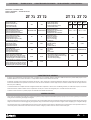 4
4
-
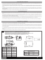 5
5
-
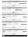 6
6
-
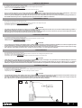 7
7
-
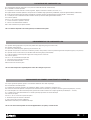 8
8
-
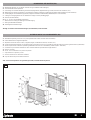 9
9
-
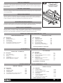 10
10
-
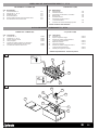 11
11
-
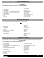 12
12
-
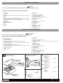 13
13
-
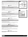 14
14
-
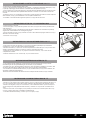 15
15
-
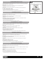 16
16
-
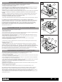 17
17
-
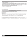 18
18
-
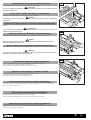 19
19
-
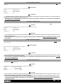 20
20
-
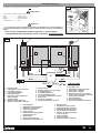 21
21
-
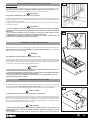 22
22
-
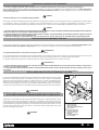 23
23
-
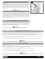 24
24
-
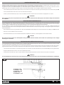 25
25
-
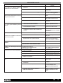 26
26
-
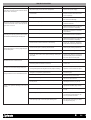 27
27
-
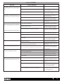 28
28
-
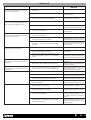 29
29
-
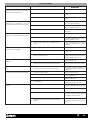 30
30
-
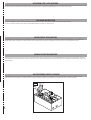 31
31
-
 32
32


Aprimatic ZT 71 Installation Instructions Manual
- Categoría
- Abridor de puerta
- Tipo
- Installation Instructions Manual
- Este manual también es adecuado para
en otros idiomas
- français: Aprimatic ZT 71
- italiano: Aprimatic ZT 71
- English: Aprimatic ZT 71
- Deutsch: Aprimatic ZT 71
Artículos relacionados
Otros documentos
-
BFT Giuno Ultra BT El manual del propietario
-
VDS PH, PH1 Guía del usuario
-
-
Telcoma CLASSIC-PLUS El manual del propietario
-
CAME FROG A24 Guía de instalación
-
Vimar SW12.T Installer Quick Manual
-
-
CAME A 180 Guía de inicio rápido
-
 RIB Prince 24V Plus Manual de usuario
-
Genius ROLLER Instrucciones de operación
