
ENGLISH
The certified and sealed instrument needs a preliminary programming of the CT
ratio relevant to the plant where the EM24 will be mounted. THIS SPECIFIC
PROGRAMMING HAS TO BE DONE ONLY ONCE AT THE FIRST SWICHING
ON OF THE INSTRUMENT. At the end of this first programming procedure the
CT ratio can be modified only by the certifying body with a complete restore of
the instrument. BEFORE SWITCHING ON THE INSTRUMENT AND PROCEE-
DING WITH THE “MID STARTING PROCEDURE”, CHECK THE INTEGRITY
OF THE SEALS AFFIXED BY THE CERTIFICATION BODY (fig 2 and 3).
JOYSTICK FUNCTIONS fig. 1
1) to access to the menu or enter the modified value;
2-3) increase/decrease the values to be modified;
4-5) increase/decrease the values to be modified.
PROGRAMMING
01
Ct rAtio: CT ratio (1.0 to 60.00k). Example: if the connected CT primary is
3000A and the secondary is 5A, the CT ratio is 600 (that is: 3000/5).
02
EnE t.rES: reset of energy and max dmd counter.
03
ConFirM: confirm of CT value. Select “no” to reprogram the CT ratio values
or “YES” to confirm it.
04
ConFirM: safety confirmation of the CT ratio value just programmed.
Select “no” to reprogram the CT ratio value or “YES” to confirm it.
Pay attention: this is the last confirmation of the CT ratio value. After this con-
firmation the value is no longer modifiable.
ITALIANO
Lo strumento sigillato e certificato MID richiede come prima programmazione
l’impostazione del rapporto TA dell’impianto al quale lo strumento sarà abbi-
nato. QUESTA PROGRAMMAZIONE SI ESEGUE UNA SOLA VOLTA ALLA
PRIMA ACCENSIONE DELLO STRUMENTO. Una volta conclusa questa
procedura preliminare il valore CT non sarà più modificabile se non rompendo
il sigillo con conseguente ripristino dello strumento dall’ente certificatore pre-
posto. PRIMA DI ACCENDERE LO STRUMENTO E PROCEDERE CON LA
PROGRAMMAZIONE PRELIMINARE MID, VERIFICARE L’INTEGRITA’ DEI
SIGILLI APPOSTI DALL’ENTE PREPOSTO (fig 2 e 3).
FUNZIONI DEL JOYSTICK fig. 1
1) conferma il valore ed entra nei sotto menù;
2-3) incrementa/decrementa i valori alfanumerici; 4-5) incrementa/decrementa
i valori alfanumerici.
PROGRAMAZIONE
01
Ct rAtio: rapporto TA (da 1,0 a 60,00k). Esempio: se il primario del TA ha
una corrente di 3000A e il secondario di 5A, il rapporto TA corrisponde a 600
(ottenuto eseguendo il calcolo: 3000/5).
02
EnE t.rES: reset dei contatori di energia e max dmd.
03
ConFirM: conferma della impostazione del CT. Selezionare “no” per ripro-
grammare il valore CT oppure “YES” per confermarlo.
04
ConFirM: conferma di sicurezza dell’impostazione del CT. Selezionare “no”
per riprogrammare il valore CT oppure “YES” per confermarlo.
Questa è l’ultima conferma dopo la quale il valore CT impostato non sarà
più modificabile.
DEUTSCH
Das bescheinigte, plombierte Messgerät benötigt eine Vorprogrammierung
des Verhältnisses Stromwandler bezüglich der Anlage, in der EM24 montiert
wird. DIESE SPEZIFISCHE PROGRAMMIERUNG IST NUR EINMAL BEI
ERSTEINSCHALT-UNG DES MESSGERÄTS VORZUNEHMEN. Am Ende
des ersten Programmierverfahrens kann das Verhältnis Stromwandler nur
Fig. 1
CARLO GAVAZZI
Automation Components
Carlo Gavazzi Controls SpA,
Via Safforze, 8 - 32100
Belluno (Italy)
Tel. +39 0437 355811,
Fax +39 0437 355880
EM24DIN MID IM ML 8021919 290419
EM24 DIN MID “Compact 3-phase Energy Analyzer”
Showed if the CT ratio is wrong. The text disappears after 2 minutes or pushing the joystick in direction 1 (fig 1).
Compare se il rapporto CT non è corretto. La scritta scompare dopo 2 minuti o premendo il joystick nella direzione 1 (fig 1).
Wird angezeigt, wenn das Verhältnis Stromwandler falsch ist. Der Text wird nach 2 Minuten ausgeblendet, ansonsten den Joystick in Richtung 1 drücken (Abb 1).
Affichage du rapport CT si celui-ci est erroné. Le texte disparaît après 2 minutes ou en poussant la manette dans la direction 1 (fig 1).
Se muestra si la relación CT es errónea. El texto desaparece después de 2 minutos o empujando el joystick en la dirección 1 (fig 1).
Vises, hvis CT-koefficienten er forkert. Teksten forsvinder efter 2 minutter eller ved at trykke på joysticket i retning 1 (fig. 1).
MID STARTING PROCEDURE - MID PROCEDURA PRELIMINARE - MID STARTVERFAHREN - PROCÉDURE DE DÉMARRAGE MID - PROCEDIMIENTO DE INICIO MID - MID STARTPROCEDURE
Fig. 2
Check the integrity of the
seal.
Verificare l’integrità del
sigillo.
Die Unversehrtheit der
Plombe kontrollieren.
Contrôler l’intégrité du
scellé.
Compruebe lo íntegro del
sello.
Kontrollér forseglingens
integritet.
Double check the set CT ratio values: exiting the procedure (YES) the set values are no longer modifiable, without breaking the seal.
Accertarsi della corretezza dei rapporti CT inseriti, concludendo la procedura (YES) i dati appena impostati non saranno più modificabili senza la rottura del sigillo.
Doppelkontrolle der eingestellten Verhältniswerte für Stromwandler: Beim Verlassen des Verfahrens (JA) sind die eingestellten Werte ohne Aufbrechen der Plombe nicht länger veränderbar.
Revérifier les valeurs de rapport CT réglées: lorsqu’on sort de la procédure (OUI) les valeurs de consigne ne sont plus modifiables, sans briser le scellé.
Compruebe minuciosamente los valores ajustados de la relación CT: saliendo del procedimiento (YES) los valores ajustados no pueden jamás ser modificados sin romper el sello.
Kontrollér de indstillede CT-koefficientværdier igen. Hvis du afslutter proceduren (JA), kan de indstillede værdier ikke længere redigeres uden at åbne forseglingen.
Before the starting programming procedure is completed the instrument shows the set CT and VT ratio values. The instrument shows the values for 3 seconds.
Prima della conclusione della procedura di programmazione preliminare lo strumento visualizza i rapporti VT e CT appena impostati. I dati vengono visualizzati dallo strumento per 3 secondi.
Bevor das Programmierstartverfahren abgeschlossen ist, zeigt das Messgerät die eingestellten Verhältniswerte für Spannungswandler und Stromwandler an. Das Messgerät zeigt die Werte 3 Sekunden lang an.
Avant que la procédure de programmation du démarrage ne soit achevée l’instrument affiche les valeurs de rapport CT et VT réglées. L’instrument affiche les valeurs pendant 3 secondes.
Antes de que haya terminado el proceso de programación de inicio, el instrumento muestra los valores ajustados de la relación CT y VT. El instrumento muestra los valores durante 3 segundos.
Før startprogrammeringsproceduren fuldføres, viser instrumentet de indstillede CT- og VT-koefficientværdier. Instrumentet viser værdierne i 3 sekunder.
von der Zertifizierungsstelle durch ein komplettes Rückspeichern des Geräts
geändert werden. VOR DEM EINSCHALTEN UND FORTFAHREN MIT DER
“MID STARTPROZEDUR”, ÜBERPRÜFEN SIE DIE UNVERSEHRTHEIT
DER VON DER ZERTIFIZIERUNGSSTELLE ANGEBRACHTEN PLOMBEN
UND SIEGEL (ABB. 2 UND 3).
JOYSTICK-FUNKTIONEN
1) Das Menü aufrufen bzw. den geänderten Wert eingeben;
2-3) Die Werte erhöhen/verringern; 4-5) Die Werte erhöhen/verringern.
PROGRAMMIERUNGSNIVEAU
01
Ct rAtio: StW-Verhältnis (von 1,0 bis 60,00k). Beispiel: Wenn der ange-
schlossene primäre Stromwandler 3000A beträgt und der sekundäre 5A,
beträgt das Stromwandlerverhältnis 600 (d.h.: 3000/5).
02
EnE t.rES: Reset des Zählers für Energie und max. Verbrauchswert.
03
ConFirM: Bestätigung des Stromwandlerwertes. „Nein“ wählen, um die
Verhältnis des Stromwandlerwerts neu zu programmieren oder „JA“, um es zu
bestätigen.
04
ConFirM: Sicherheitsbestätigung des soeben programmierten Verhältnisses
des Stromwandlerwertes. „Nein“ wählen, um das Verhältnis des
Stromwandlerwerts neu zu programmieren oder “JA”, um es zu bestätigen
.
Bedenken Sie: Dies ist die letzte Bestätigung des Werts des
Stromwandlerverhältnisses. Nach dieser Bestätigung kann es nicht verän-
dert werden.
FRANÇAIS
L’instrument certifié et plombé a besoin d’une programmation préliminaire
du rapport CT pertinente à l’équipement où l’EM24 sera monté. CETTE
PROGRAMMATION SPÉCIFIQUE DOIT ÊTRE EFFECTUÉE UNE SEULE
FOIS LORS DU PREMIER ALLUMAGE DE L’INSTRUMENT. Au terme de
cette première procédure de programmation le rapport CT peut être modifié
uniquement par l’organisme de certification avec une restauration complète de
l’instrument. AVANT D’ALLUMER L’INSTRUMENT ET DE PROCÉDER À LA
“PROCÉDURE DE DÉMARRAGE MID”, CONTRÔLER L’INTÉGRITÉ DES
SCELLÉS APPOSÉS PAR L’ORGANISME DE CERTIFICATION (fig 2 et 3).
FONCTIONS DU JOYSTICK
1) accède au menu ou insérer la valeur modifiée;
2-3) augmente/diminue les valeurs à modifier; 4-5) augmente/diminue les valeurs à
modifier.
PROGRAMMATION
01
Ct rAtio: ratio CT (de 1,0 à 60,00k). Exemple: si le primaire du TC a un
courant de 3000A et le secondaire de 5A, le ratio TC correspond à 600 (obtenu
en effectuant le calcul: 3000/5).
02
EnE t.rES: réinitialisation du compteur d’énergie et max dmd.
03
ConFirM: confirmation valeur CT. Sélectionner “non” pour reprogrammer la
valeur de rapport CT ou “OUI” pour la confirmer.
04
ConFirM: confirmation de sécurité valeur de rapport CT qui vient d’être
programmée. Sélectionner “non” pour reprogrammer la valeur de rapport ou
“OUI” pour la confirmer. Faire attention: il s’agit de la dernière confirmation des
valeurs de rapport CT. Après cette confirmation les valeurs ne sont plus
modifiables.
ESPAÑOL
El instrumento certificado y con sello precisa de una programación previa de
la relación CT según sea la instalación donde será montado el EM24. ESTA
PROGRAMACIÓN ESPECÍFICA TIENE QUE SER REALIZADA SOLAMENTE
UNA VEZ EN EL PRIMER ENCENDIDO DEL INSTRUMENTO. Al finalizar
este primer procedimiento de programación, la relación CT sólo puede ser
modificada por la entidad certificadora por medio de una completa puesta a
cero del instrumento. ANTES DE ENCENDER EL INSTRUMENTO Y PRO-
CEDER CON EL “PROCEDIMIENTO DE INICIO MID”, COMPRUEBE LA
INTEGRIDAD DE LOS SELLOS DE LA ENTIDAD CERTIFICADORA (fig 2).
FUNCIONES DEL JOYSTICK fig. 1
1) para acceder al menú o introducir el valor modificado.
2-3) aumentar/disminuir los valores a modificar. 4-5) aumentar/disminuir los
valores a modificar.
PROGRAMACIÓN
01
Ct rAtio: relación del trafo de intensidad CT (1,0 a 60,00k). Ej.: si el prima-
rio del trafo conectado es 3000A y el secundario es 5A, la relación del trafo de
intensidad es 600 (es decir, 3000/5).
02
EnE t.rES: puesta a cero del contador de energía y máx. dmd.
03
ConFirM: confirmación de valor CT. Seleccione “no” para volver a progra-
mar los valores de la relación CT o “YES” para confirmarlos.
04
ConFirM: confirmación de seguridad de los valores de la relación CT justo
al ser programados. Seleccione “no” para volver a programar los valores de la
relación CT o “YES” para confirmarlos
. Atención: ésta es la última confirmación
de los valores de la relación CT. Después de esta confirmación los valores
no podrán jamás ser modificados.
DANSK
Det certificerede og forseglede instrument kræver en foreløbig programme-
ring af CT-koefficienten vedrørende det anlæg, hvor EM24 skal monteres.
DENNE SPECIFIKKE PROGRAMMERING MÅ KUN UDFØRES EN GANG
VED DEN FØRSTE TÆNDING AF INSTRUMENTET. Ved afslutningen af
den første programmeringsprocedure kan CT-koefficienten kun ændres af
certificeringsorganet gennem en fuldstændig gendannelse af instrumentet.
FØR INSTRUMENTET TÆNDES, OG DER FORTSÆTTES MED “MID
STARTPROCEDURE”, SKAL INTEGRITETEN AF FORSEGLINGEN, SOM
ER PÅFØRT AF CERTIFICERINGSMYNDIGHEDERNE, KONTROLLERES
(fig. 2 og 3).
JOYSTICKFUNKTIONER, fig. 1
1) For adgang til menuen eller indtastning af den redigerede værdi.
2-3) Forøg/formindsk de værdier, der skal redigeres. 4-5) Forøg/formindsk de
værdier, der skal redigeres.
PROGRAMMING
01
Ct rAtio: CT-koefficient (1,0 til 60,00 k). Eksempel: Hvis den tilsluttede
hoved-CT er 3000 A og den sekundære er 5 A, er CT-koefficienten 600 (dvs.
3000/5).
02
EnE t.rES: Nulstilling af energi og maks. dmd-tæller.
03
ConFirM: Bekræftelse af CT-værdi. Vælg “NEJ” for at omprogrammere
CT-koefficientværdierne eller “JA” for at bekræfte.
04
ConFirM: Sikkerhedsbekræftelse af den CT-koefficientværdi, der lige er
blevet programmeret. Vælg “NEJ” for at omprogrammere CT-koefficientværdien
eller “JA” for at bekræfte. Pas på: Dette er den sidste bekræftelse af
CT-koefficientværdier
.
End of the procedure. Instrument in measuring mode. Strumento in modalità
misura. Ende des Verfahrens. Messgerät im Messmodus. Fin de la procédu-
re. Instrument en mode mesure. Fin del procedimiento. Instrumento en el
modo de medición. Slut på procedure. Instrument i måletilstand.
Check the integrity of the seals.
Verificare l’integrità dei sigilli.
Die Unversehrtheit der Plomben kontrollieren.
Contrôler l’intégrité des scellés.
Compruebe la integridad de los sellos.
Kontrollér forseglingernes integritet.
Fig. 3
AV5

ENGLISH
• MID certified system: 3-phase with neutral only (3Pn),
50Hz;
• MID certified variables: total imported active energy
kWh(+);
• Not certified variables: exported active energy kWh(-),
any reactive energy kvarh, any partial active energy, any
instantaneous variable;
• Application D is not available in MID certified meters;
• Connection with voltage transformer is not MID certified;
• Interfaces are not MID certified and have not any effect
on the measurements;
• Auxiliary power supply (supply “L” or “D” in version
AV5) is not MID certified;
• Connect AV2, AV9 meters according to the connection
diagram [4];
• Connect AV5 meters according to the connection dia-
gram [5].
• EM24-DINAV5 (self-supplied) is tested for energy sup-
ply networks with interferences in the frequency range
from 2 kHz to 150kHz. Other models are not tested for
such range of interferences.
• In order to achieve the protection against dust and
water required by the norms harmonized to MID, the
meter must be used only installed in IP51 (or better)
cabinets.
[4] [5]
65A (AV2, AV9) 5A (AV5)
ITALIANO
• Sistema certificato MID: Trifase con neutro (3Pn), 50Hz;
• Variabili certificate MID: energia attiva totale importata
kWh (+);
• Variabili non certificate: energia attiva esportata kWh (-),
qualsiasi energia reattiva kvarh, qualsiasi energia attiva
parziale, qualsiasi variabile istantanea;
• L’applicazione D non è disponibile nei contatori certificati
MID;
• La connessione con trasformatore di tensione non è
certificata MID;
• Le interfacce non sono certificate MID e non hanno alcun
effetto sulle misurazioni;
• L’alimentazione ausiliaria (alimentazione “L” o “D” nella
versione AV5) non è certificata MID;
• Collegare i contatori AV2, AV9 secondo lo schema di
collegamento [4];
• Collegare i contatori AV5 secondo lo schema di col-
legamento [5].
• EM24-DINAV5 (auto-alimentato) è testato per reti di ali-
mentazione con interferenze nel range 2 kHz - 150kHz.
Gli altri modelli non sono testati per queste interferenze.
• Al fine di conseguire la protezione contro polvere e
acqua richieste dalle norme armonizzate MID, il conta-
tore deve essere utilizzato solo se installato in armadi-
etti con grado di protezione IP51 (o superiore).
DEUTSCH
• MID-zertifiziertes System: nur 3-phasig mit Nullleiter
(3Pn), 50 Hz;
• MID-zertifizierte Messgrößen: importierte Wirkenergie
gesamt kWh(+);
• Nicht zertifizierte Messgrößen: abgegebene Wirkenergie
kWh(-), jede Blindenergie kvarh, jede partielle
Wirkenergie, jede Momentanmessgröße;
• Anwendung D ist nicht in MID-zertifizierten Zählern
verfügbar;
• Anschluss an Spannungstransformator ist nicht MID-
zertifiziert;
• Schnittstellen sind nicht MID-zertifiziert und haben kein-
erlei Auswirkung auf die Messungen;
• Hilfsstromversorgung (Versorgung „L“ oder „D“ in
Version AV5) ist nicht MID-zertifiziert;
• Anschluss der Zähler AV2, AV9 gemäß des
Anschlussdiagramms [4];
• Anschluss der Zähler AV5 gemäß des
Anschlussdiagramms [5].
• EM24-DINAV5 (selbstversorgt) ist fur
Energieversorgungnetze mit lnterferenzen im
Frequenzbereien 2kHz-150 kHz getestett. Andere
Modelle werden nicht auf solche lnterferenzen getestet.
• Um den Schutz gegen Staub und Wasser entsprechend
der spezifischen Normen gemäß MID zu erreichen,
muss der Energiezähler in einem Gehäuse oder
Schaltschrank mit Schutzgrad IP51 (oder höher) instal-
liert werden.
FRANÇAIS
• Système certifié MID: Triphasé avec neutre uniquement
(3Pn), 50 Hz;
• Variables certifiées MID: énergie active totale importée
kWh (+);
• Variables pas/non certifiées: énergie active exportée
kWh (-), toute énergie reactive kvarh, toute énergie
active partielle, toute variable instantanée;
• L’application D n’est pas disponible dans les compteurs
certifiés MID;
• La connection avec le transformateur de tension n’est
pas certifiée MID;
• Les interfaces ne sont pas certifiées MID et n’ont pas
aucun effet sur les mesures;
• L’alimentation auxiliaire (alimentation “L” ou “D” dans la
version AV5) n’est pas certifiée MID;
• Connecter les compteurs AV2, AV9 selon le schéma de
câblage [4];
• Connecter les compteurs AV5 selon le schéma de
câblage [5].
• EM24-DINAV5 (auto-alimenté ) est testé pour les
réseaux d’alimentation avec des interférence dans la
gamme de fréquences de 2 kHz à 150 kHz150kHz. Les
autres modéles ne sont pas testés.
• Afin d’assurer la protection contre la poussière et l’eau
conformément aux normes MID, le compteur doit être
utilisé dans des boîtiers avec degré de protection IP51
(ou supérieur).
ESPAÑOL
• Sistema certificado MID: Trifásico con neutro (3Pn),
50Hz;
• Variables certificadas MID: energía activa total consu-
mida kWh (+);
• Variables no certificadas: energía activa generada kWh
(-), cualquier energía reactiva kvarh, cualquier energía
activa parcial, cualquier variable instantánea;
• Los medidores certificados MID no disponen de la
opción D;
• La conexión con el transformador de tensión no cumple
con la directiva MID;
• Las interfaces no cumplen con la directiva MID y no
tienen efecto alguno sobre las mediciones;
• La alimentación auxiliar (alimentación “L” u “D” en la
versión AV5) no cumple con la directiva MID;
• Conectar los medidores AV2, AV9 según se indica en
el diagrama de conexión [4];
• Conectar los medidores AV5 según se indica en el dia-
grama de conexión [5].
• EM24-DINAV5 (autoalimentado ) se prueba para para
redes con interferencias en un rango de frecuencia
de 2kHz a 150kHz. Los otros modelos no han sido
probados.
• Con el fin de lograr la protecciòn contra polvo y agua
requerida por las normas armonizadas segùn MID, el
medidor debe instalarse sòlo en armarios con protec-
ciòn IP51 o superior.
DANSK
• Certificeret MID-system: 3-faset kun med nulforbindelse
(3Pn), 50Hz;
• Certificerede MID-variable: totalt importeret aktiv energi
kWh(+);
• Ikke-certificerede variable: eksporteret aktiv energi
kWh(-), eventuel reaktiv energi kvarh, eventuel delvis
aktiv energi, eventuel øjebliksvariabel;
• D-applikation er ikke tilgængelig i certificerede MID-
målere;
• Tilslutning med spændingstransformer er ikke MID-
certificeret;
• Grænseflader er ikke MID-certificeret og påvirker ikke
målingerne;
• Hjælpestrømforsyning (tilslutning af “L” eller “D” i ver-
sion AV5) er ikke MID-certificeret;
• Tilslut AV2- og AV9-målere i henhold til ledningsdia-
grammet [4];
• Tilslut AV5-målere i henhold til ledningsdiagrammet [5].
• EM24-DINAV5 (selvforsynet ) testes for strømnetværk
med interferens ii området 2 kHz -150 kHz. De andre
modeller testes ikke.
• Far at opnå beskyttelse mod støv og vand, der kræves
af noemerne harmoniseret til MID,må måleren kun bru-
ges i IP51 (eller bedre) frysere.
ADDITIONAL NOTES FOR MID COMPLIANCE - NOTE AGGIUNTIVE PER CONFORMITA’ CON LA DIRETTIVA MID - ZUSÄTZLICHE HINWEISE ZUR MID-KONFORMITÄT - NOTES ADDITIONNELLES DE CONFORMITÉ À LA DIRECTIVE MID - NOTAS
ADICIONALES SOBRE EL CUMPLIMIENTO CON LA DIRECTIVA MID - YDERLIGERE BEMÆRKNINGER TIL OVERENSSTEMMELSE MED MID-DIREKTIVET
AV5 - AV2 - AV9

ENGLISH
GENERAL WARNINGS
DANGER: live parts. Heart attack, burns and other
injuries. Disconnect the power supply and load before
installing the analyzer. Protect terminals with covers.
The energy analyzer should only be installed by qualied/
authorized personnel.
These instructions are an integral part of the product. They
should be consulted for all situations tied to installation and
use. They should be kept within easy reach of operators, in
a clean place and in good conditions.
Cleaning
Use a slightly dampened cloth to clean the instrument display; do not use
abrasives or solvents.
SERVICE AND WARRANTY
In the event of malfunction, fault or for information on the warranty,
contact the CARLO GAVAZZI branch or distributor in your country.
Connection diagrams
65A Self power supply, system type selection 3P.n
[1]- 3-ph, 4-wire unbalanced/balanced load. F= 250mA time-delay
65A Self power supply, system type selection 3P
[2]- 3-ph, 3-wire, unbalanced/balanced load
65A Self power supply, system type selection 2P
[3]- 2-ph, 3-wire, unbalanced/balanced load. F= 250mA time-
delay
65A Self power supply, system type selection 1P
[4]- 1-ph, 2-wire. F= 250mA time-delay
10A System type selection 3P.n
[5]- 3-ph, 4-wire, unbalanced load, 3-CT connection. F= 250mA
time-delay
10A System type selection 3P
[6]- 3-ph, 3-wire, unbalanced load, 3-CT connection. F= 250mA
time-delay
[7]- 3-ph, 3-wire, unbalanced load, 2-CT connnections
(ARON). F= 250mA time-delay
10A System type selection 3P.1
[8]- 3-ph, 3-wire, balanced load, 1-CT connection. F= 250mA time-
delay
[9]- 3-ph, 4-wire, balanced load, 1-CT connection. F= 250mA time-
delay
10A System type selection 2P
[10]- 2-ph, 3-wire, 2-CT connection. F= 250mA time-delay
10A System type selection 1P
[11]- 1-ph, 2-wire, 1-CT connection. F= 250mA time-delay
EM24 DIN E1
10A
AV5
[1]
[2]
[3]
[4]
[5]
[6]
[7]
[8]
[10] [11]
[9]
AV2
AV5
ITALIANO
AVVERTENZE GENERALI
PERICOLO: parti sotto tensione. Arresto cardiaco,
bruciature e altre lesioni. Scollegare l’alimentazione e
il carico prima di installare l’analizzatore. Proteggere i
morsetti con le coperture. L’installazione degli analizzatori
d’energia deve essere eseguita solo da persone qualicate/
autorizzate.
Queste istruzioni sono parte integrante del prodotto. Devono
essere consultate per tutte le situazioni legate all’installazione e
all’uso. Devono essere conservate in modo che siano
accessibili agli operatori, in un luogo pulito e mantenuto in
buone condizioni.
Pulizia
Per mantenere pulito il display dello strumento installato usare un panno
leggermente inumidito; non usare abrasivi o solventi.
ASSISTENZA E GARANZIA
In caso di malfunzionamento, guasto o informazioni sulla garanzia contattare
la liale CARLO GAVAZZI o il distributore nel paese di appartenenza.
Schemi di collegamento
65A, selezione sistema tipo 3P.n
[1]- 3 fasi, 4 fili carico squilibrato/equilibrato. F= 250mA ritar-
dato
65A, selezione sistema tipo 3P
[2]- 3 fasi, 3 fili, carico squilibrato/equilibrato
65A, selezione sistema tipo 2P
[3]- 2 fasi, 3 fili, carico squilibrato/equilibrato. F= 250mA ritar-
dato
65A, selezione sistema tipo 1P
[4]- 1 fase, 2 fili. F= 250mA ritardato
10A, selezione sistema tipo 3P.n
[5]- 3 fasi, 4 fili, carico squilibrato, connessione da 3 TA.
F= 250mA ritardato
10A, selezione sistema tipo 3P
[6]- 3 fasi, 3 fili, carico squilibrato, connessione da 3 TA.
F= 250mA ritardato
[7]- 3 fasi, 3 fili, carico squilibrato, connessione da 2 TA
(ARON). F= 250mA ritardato
10A, selezione sistema tipo 3P.1
[8]- 3 fasi, 3 fili, carico equilibrato, connessione da 1 TA.
F= 250mA ritardato
[9]- 3 fasi, 4 fili, carico equilibrato, connessione da 1 TA.
F= 250mA ritardato
10A, selezione sistema tipo 2P
[10]- 2 fasi, 3 fili, connessione da 2 TA. F= 250mA ritardato
10A, selezione sistema tipo 1P
[11]- 1 fase, 2 fili, connessione da 1 TA. F= 250mA ritardato
DEUTSCH
ALLGEMEINE SICHERHEITSHINWEISE
GEFAHR: Spannungsführende Teile. Gefahr von
Herzstillstand, Verbrennungen und sonstigen
Verletzungen. Vor Beginn der Installation des
Energieanalysators elektrische Versorgung und Last trennen.
Die Klemmen mit den entsprechenden Abdeckungen
schützen. Die Installation der Energieanalysatoren darf nur
von qualizierten und befugten Personen ausgeführt werden.
Diese Anweisungen sind fester Bestandteil des Produkts. Sie
müssen vor der Installation und Verwendung sorgfältig gelesen
werden. Diese Anweisungen sicher an einem sauberen Ort
aufbewahren und für Bedienpersonen jederzeit verfügbar halten.
Reinigung
Das Display am installierten Gerät mit einem leicht befeuchteten Tuch
reinigen. Keine Scheuer- oder Lösungsmittel verwenden.
KUNDENDIENST UND GARANTIE
Bei Störungen oder Fehlern bzw. wenn Sie Auskünfte bezüglich der Garantie
benötigen, kontaktieren Sie bitte die Niederlassung von CARLO GAVAZZI
oder den zuständigen Vertriebspartner in Ihrem Land.
Anschlusspläne
65A, Systemwahl: 3P.n
[1]- 3-ph, 4-Adern, asym./sym. Last
65A, Systemwahl: 3P
[2]- 3-ph, 3-Adern, asym./sym. Last.
65A, Systemwahl: 2P
[3]- 2-ph, 3-Adrig, asym./sym. Last. F= 250mA zeitverzögert
65A, Systemwahl: 1P
[4]- 1-ph, 2-Adrig. F= 250mA zeitverzögert
(10A) Systemwahl: 3P.n
[5]- 3-ph, 4-Adrig, asymmetrische Last, 3
Stromwandleranschluss. F= 250mA zeitverzögert
10A, Systemwahl: 3P
[6]- 3-ph, 3-Adrig, asymmetrische Last, 3
Stromwandleranschlüsse. F= 250mA zeitverzögert
[7]- 3-ph, 3-Adrig, asymmetrische Last, 2
Stromwandleranschlüsse (ARON)
10A, Systemwahl: 3P.1
[8]- 3-ph, 3-Adrig, symmetrische Last, 1-Stromwandleranschluss.
F= 250mA zeitverzögert
[9]- 3-ph, 4-Adrig, symmetrische Last, 1-Stromwandleranschluss.
F= 250mA zeitverzögert
10A, Systemwahl: 2P
[10]- 2-ph, 3-Adrig, 2 Stromwandleranschlüsse. F= 250mA
zeitverzögert
10A, Systemwahl: 1P
[11]- 1-ph, 2-Adrig, 1-Stromwandleranschluss. F= 250mA
zeitverzögert
FRANÇAIS
AVERTISSEMENTS GÉNÉRAUX
RISQUE : pièces sous tension Crise cardiaque,
brûlures et autres blessures Débranchez
l’alimentation électrique et chargez le dispositif avant
d’installer l’analyseur. Protégez les bornes avec des
couvercles. L’analyseur d’énergie doit être installé par un
personnel qualié/agréé.
Ces instructions sont partie intégrante du produit. Elles doivent
être consultées pour toutes les situations liées à l’installation et
à l’utilisation. Elles doivent être conservées de manière à être
facilement accessibles aux opérateurs, dans un endroit propre
et en bon état.
Nettoyage
Utilisez un chion légèrement mouillé pour nettoyer l’écran de l’instrument ;
n’utilisez pas d’abrasifs ou de solvants.
ENTRETIEN ET GARANTIE
En cas de dysfonctionnement, de panne ou de besoin d’informations sur
la garantie, contactez la liale ou le distributeur CARLO GAVAZZI de votre
pays.
Schémas de branchement
65A Entrée auto-alimentée, sélection du type de réseau: 3P.n
[1]- 3 phases, 4 câbles, charge équilibrée/déséquilibrée. F=
250mA retardé
65A Entrée auto-alimentée, sélection du type de réseau: 3P
[2]- 3 phases, 3 câbles, charge équilibrée/déséquilibrée.
65A Entrée auto-alimentée, sélection du type de réseau: 2P
[3]- 2 phases, 3 câbles, charge équilibrée/déséquilibrée. F=
250mA retardé.
65A Entrée auto-alimentée, sélection du type de réseau: 1P
[4]- 1 phase, 2 câbles. F= 250mA retardé
10A Sélection du type de réseau: 3P.n
[5]- 3 phases, 4 câbles, charge déséquilibrée, connexions 3 TC.
F= 250mA retardé
10A Sélection du type de réseau: 3P
[6]- 3 phases, 3 câbles, charge déséquilibrée, connexions 3 TC.
F= 250mA retardé
[7]- 3 phases, 3 câbles, charge déséquilibrée, connexions 2 TC
(ARON). F= 250mA retardé
10A Sélection du type de réseau: 3P.1
[8]- 3 phases, 3 câbles, charge équilibrée, connexions 1 TC. F=
250mA retardé
[9]- 3 phases, 4 câbles, charge équilibrée, connexions 1 TC. F=
250mA retardé
10A Sélection du type de réseau: 2P
[10]- 2 phases, 3 câbles, connexions 2 TC. F= 250mA retardé
10A Sélection du type de réseau: 1P
[11]- 1 phases, 2 câbles, connexions 1 TC. F= 250mA retardé
ESPAÑOL
ADVERTENCIAS GENERALES
PELIGRO: elementos sometidos a tensión. Ataque al
corazón, quemaduras u otras lesiones. Desconecte
la fuente de alimentación y carga antes de instalar el
analizador. Proteja los bornes con casquillos aislantes. El
analizador de energía sólo lo debe instalar personal
cualicado/ autorizado.
Estas instrucciones forman parte integral del producto. Se
tienen que consultar para todo lo que tenga que ver con la
instalación y el funcionamiento. Se deben guardar donde estén
accesibles para los operarios, en un lugar limpio y en buenas
condiciones.
Limpieza
Utilice un trapo ligeramente mojado para limpiar la pantalla; no use
abrasivos o disolventes.
REPARACIÓN Y GARANTÍA
Si se producen fallos o anomalías en el funcionamiento o quiere conocer
las condiciones de garantía póngase en contacto con CARLO GAVAZZI
lial o distribuidor de su país.
Diagramas de conexión
65A, Autoalimentado, selección del sistema: 3P.n
[1]- Trifásico, 4 hilos, carga equilibrada y desequilibrada.
F= 250mA temporizado.
65A, Autoalimentado, selección del sistema: 3P
[2]- Trifásico, 3 hilos, carga equilibrada y desequilibrada
65A, Autoalimentado, selección del sistema: 2P
[3]- Bifásico, 3 hilos, carga equilibrada y desequilibrada.
F= 250mA temporizado.
65A, Autoalimentado, selección del sistema: 1P
[4]- Monofásico, 2 hilos. F= 250mA temporizado.
10A, selección del sistema: 3P.n
[5]- Trifásico, 4 hilos, carga desequilibrada, conexión 3 trafos
de intensidad. F= 250mA temporizado.
10A, selección del sistema: 3P
[6]- Trifásico, 3 hilos, carga desequilibrada, conexión 3 trafos
de intensidad. F= 250mA temporizado.
[7]- Trifásico, 3 hilos, carga desequilibrada, conexiones
2 trafos de intensidad (ARON). F= 250mA temporizado.
10A, selección del sistema: 3P.1
[8]-Trifásico, 3 hilos, carga equilibrada, conexión 1 trafo de
intensidad. F= 250mA temporizado.
[9]- Trifásico, 4 hilos, carga equilibrada, conexión 1 trafo de
intensidad. F= 250mA temporizado.
10A, selección del sistema: 2P
[10]- Bifásico, 3 hilos, conexión 2 trafos de intensidad.
F= 250mA temporizado.
10A, selección del sistema: 1P
[11]- Monofásico, 2 hilos, conexión 1 trafo de intensidad.
F= 250mA temporizado.
DANSK
GENERELLE ADVARSLER
FARE: spændingsførende dele. Hjerteanfald,
forbrændinger og andre kvæstelser. Afbryd
strømtilførslen og belastning, inden analysatoren
installeres. Beskyt klemmerne med afdækninger.
Energianalysatoren må kun installeres af fagkyndigt/
autoriseret personale.
Disse instruktioner er en integreret del af produktet. De skal
altid konsulteres i alle situationer, som drejer sig om installation
og brug. De skal være tilgængelige for operatørerne, opbevares
på et rent sted og holdes i god stand.
Rengøring
Brug en let fugtig klud til at gøre instrumentdisplayet rent; brug ikke
slibende midler eller opløsningsmidler.
SERVICE OG GARANTI
Hvis der opstår fejlfunktioner og defekter, eller hvis der er brug for
oplysninger om garantien, bedes du kontakte den lokale CARLO
GAVAZZI-forhandler eller afdeling.
Tilslutningsdiagrammer
65 A, egen strømforsyning, valg af systemtype: 3-fa.n
[1]- 3-fa.n, 4 ledere, ubalanceret/balanceret belastning.
F= 250mA tidsforsinkelse
65 A, egen strømforsyning, valg af systemtype: 3P
[2]- 3-fa.,3 ledere, ubalanceret/balanceret belastning.
F= 250mA tidsforsinkelse
65 A, egen strømforsyning, valg af systemtype: 2P
[3]- 2-fa., 3 ledere, ubalanceret/balanceret belastning.
F= 250mA tidsforsinkelse
65 A, egen strømforsyning, valg af systemtype:
[4]- 1-fa., 2 ledere. F= 250mA tidsforsinkelse
10 A, valg af systemtype: 3-fa.n
[5]- 3-fa., 4 ledere, ubalanceret belastning, 3-CT tilslutning.
F= 250mA tidsforsinkelse
10 A, valg af systemtype: 3P
[6]- 3-fa., 3 ledere, ubalanceret belastning, 3-CT tilslutning.
F= 250mA tidsforsinkelse
[7]- 3-fa., 3 ledere, ubalanceret belastning, 2-CT tilslutninger
(ARON). F= 250mA tidsforsinkelse
10 A, valg af systemtype: 3-fa.1
[8]- 3-fa., 3 ledere, balanceret belastning, 1-CT tilslutning.
F= 250mA tidsforsinkelse
[9]- 3-fa., 4 ledere, balanceret belastning, 1-CT tilslutning.
F= 250mA tidsforsinkelse
10 A, valg af systemtype: 2P
[10]- 2-fa., 3 ledere, 2-CT tilslutning. F= 250mA tidsforsinkelse
10 A, valg af systemtype: 1P
[11]- 1-fa., 2 ledere, 1-CT tilslutning. F= 315 mA
65A
AV2
UCS soware
www.productselection.net/Download/UK/ucs.zip
User manual
www.productselection.net/MANUALS/UK/em24_E1_im_use.pdf
2011/65/EU (Rohs)
MID: EN5470-1, EN50470-3
Electromagnec compability (EMC) - emissions and im-
munity: IEC/EN62052-11
Electrical safety: EN50470-1, EN61010-1
Accuracy: EN50470-3, IEC/EN 62053-21, 62053-23

TECHNICAL SPECIFICATIONS
Voltage
AV2 AV5
Connection Direct Direct
Rated voltage L-N
(from Un min to Un max)
From 120 to 277 V
Rated voltage L-L
(from Un min to Un max)
From 208 to 480 V
Voltage tolerance -20, +15%
Overload Continuous: 1.2 Un max
For 500 ms: 2 Un max
Input Impedance Refer to “Power supply”
Frequency 50/60Hz
Current
AV2 AV5
Connection Direct Via CT
CT ratio - PFA, PFB: 1 to 2615
X: 1 to 6975
In - 5 A
Ib 10 A -
Imin 0.5 A 0.05 A
Imax 65 A 10 A
Ist 0.04 A 0.01 A
Overload
• Continuous
• 500 ms
• 10ms
65A @50Hz
-
1950A,@ 50Hz
10A @50Hz
200A, @ 50Hz
-
Input
impedance
< 4.9 VA < 2.1 VA
Crest factor 4 3
Power supply
Type Self power supply
Consumption < 2.9 W; 4.7 VA
Ethernet port
Protocols Modbus TCP/IP
Client connections Maximum 5 simultaneously
Connection type
RJ45 connector (10 Base-T, 100 Base-TX), maximum
distance 100 m
Configuration
parameters
IP address
Subnet mask
Gateway
TCP/IP port
DHCP enable/disable
Configuration mode
Via keypad or UCS software
Note: see User manual for default parameters and configuration.
LED
Red. Weight: proportional to energy consumption and depending on the CT
and VT/PT ratio product (16 Hz maximum frequency):
AV5 models
CT*VT Weight (kWh per pulse)
≤ 7 0.001
> 7 ≤ 70.0 0.01
> 70 ≤ 700.0 0.1
> 700 1
AV2 models
CT*VT Weight (kWh per pulse)
-
0.001
General
Protection degree Front: IP50. Screw terminals: IP20.
Insulation (for 1 minute) 4kV (between measurement input and Ethernet port)
Measurement category Cat. III
Dielectric strength 4000 VRMS for 1 minute.
Connections Screw-type.
Cable cross-section area AV2: max. 16 mm
2
; min. 2.5 mm
2
(by cable lug)
AV5: Max. 1.5 mm
2
Mounting DIN-rail.
Weight 400 g (packing included).
Environmental specifications
Operating temperature -25°C to +55°C (-13°F to 131°F)
Storage temperature -30°C to +70°C (-22°F to 158°F)
UL NOTES: the CTs used for current measurement (AV5 version) must guar-
antee at least a basic insulation between primary and secondary.
ENGLISH
CARATTERISTICHE TECNICHE
Tensione
AV2 AV5
Connessione Diretta Diretta
Tensione nominale L-N
(da Un min a Un max)
Da 120 a 277 V
Tensione nominale L-L
(da Un min a Un max)
Da 208 a 480 V
Tolleranza tensione -20, +15%
Sovraccarico Continuo: 1.2 Un max
Per 500 ms: 2 Un max
Impedenza d’ingresso Vedere “Alimentazione”
Frequenza 50/60Hz
Corrente
AV2 AV5
Connessione Diretta Via CT
Rapporto CT - PFA, PFB: da 1 a 2615
X: da 1 a 6975
In - 5 A
Ib 10 A -
Imin 0,5 A 0,05 A
Imax 65 A 10 A
Ist 0,04 A 0,01 A
Sovraccarico
Continuo
• 500 ms
• 10ms
65A @50Hz
-
1950A,@ 50Hz
10A @50Hz
200A, @ 50Hz
-
Impedenza
d’ingresso
< 4,9 VA < 2,1 VA
Fattore di cresta 4 3
Alimentazione
Tipo Autoalimentato
Consumo
< 2,9 W; 4,7 VA
Porta Ethernet
Protocollo Modbus TCP/IP
Connessioni client Massimo 5 contemporanee
Tipo collegamento
Connettore RJ45 (10 Base-T, 100 Base-TX),
distanza massima 100 m
Parametri configurazione
Indirizzo IP
Subnet mask
Indirizzo gateway
Porta TCP/IP
abilita/disabilita DHCP
Modalità configurazione
Via keypad or UCS software
Note: consultare il Manuale utente per i parametri predefiniti e la configu-
razione.
LED
Rosso. Peso: proporzionale al consumo di energia e dipendente dal pro-
dotto dei rapporti di TA e di TV (frequenza max: 16Hz):
Modelli AV5
CT*VT Peso (kWh per impulso)
≤ 7 0,001
> 7 ≤ 70,0 0,01
> 70 ≤ 700,0 0,1
> 700 1
Modelli AV2
CT*VT Peso (kWh per impulso)
-
0,001
Generali
Grado di protezione frontale: IP50. Connessioni: IP20.
Isolamento (per 1 minuto) 4kV (tra ingresso di misura e porta Ethernet)
Categoria di misura Cat. III
Rigidità dielettrica 4000 VRMS per 1 minuto.
Connessioni a vite.
Sezione del cavo AV2: max. 16 mm
2
; min. 2.5 mm
2
(tramite capocorda)
AV5: Max. 1.5 mm
2
Montaggio a guida DIN.
Peso 400 g (imballo incluso).
Caratteristiche ambientali
Temperatura di funzionamento da -25°C a +55°C (da -13°F a 131°F)
Temperatura di immagazzinamento da -30°C a +70°C (da -22°F a 158°F)
ITALIANO
DEUTSCH
FRANÇAIS
ESPAÑOL
DANSK
TECHNISCHE DATEN
Spannung: Modelle AV2, AV5
AV2 AV5
Anschlüsse Direkt Direkt
Nennspannung L-N
(Un min bis Un max)
120 bis 277 V
Nennspannung L-L
(Un min bis Un max)
208 bis 480 V
Spannungstoleranz -20, +15%
Überlastspannung Dauer: 1.2 Un max
Für 500 ms: 2 Un max
Eingangsimpedanz Siehe “Stromversorgung”
Frequenz 50/60Hz
Strom
AV2 AV5
Anschlüsse
Direkt
Mittels CT
CT
-Verhältnis - PFA, PFB: 1 bis 2615
X: 1 bis 6975
In - 5 A
Ib 10 A -
Imin 0,5 A 0,05 A
Imax 65 A 10 A
Ist 0,04 A 0,01 A
Überlaststrom
Dauer
• 500 ms
• 10ms
65A @50Hz
-
1950A,@ 50Hz
10A @50Hz
200A, @ 50Hz
-
Eingangsimpedanz < 4,9 VA < 2,1 VA
Scheitelwertfaktor
4 3
Stromversorgung
Typ eigenversorgt
Leistungsafunahme
< 2,9 W; 4,7 VA
Ethernet-Port
Protokolle Modbus TCP/IP
Client-Verbindungen Maximal 5 gleichzeitig
Anschlusstyp
RJ45-Anschluss (10 Base-T, 100 Base-TX),
maximaler Abstand 100 m
Konfigurationsparameter
IP-Adresse
Subnetzmaske
Gateway
TCP/IP-Port
DHCP aktivieren / deaktivieren
Konfigurationsmodus
Per Keypad oder UCS-Software
Hinweis: siehe Benutzerhandbuch für Standardparameter und Konfiguration.
LED-Leuchten
Rot. Gewichtung: Proportional zum Energieverbrauch und abhängig vom
Produkt der Verhältnisse TA und TV (Max. Frequenz: 16 Hz):
Modelle AV5
CT*VT Gewichtung (kWh pro Impuls)
≤ 7 0,001
> 7 ≤ 70,0 0,01
> 70 ≤ 700,0 0,1
> 700 1
Modelle AV2
CT*VT Gewichtung (kWh pro Impuls)
-
0,001
Allgemeines
Schutzgrad IP50 (Vorderseite).
Schraubenklemmen: IP20.
Isolationsspannung
(für 1 Minute)
4kV (zwischen Messeingang und Ethernet-Port)
Messkategorie Kat. III
Durchschlagfestigkeit 4000 VRMS für 1 Minute.
Anschlüsse Schraubklemmen.
Kabel-querschnitt AV2: max. 16 mm
2
; min. 2.5 mm
2
(mit Kabelschuh)
AV5: Max. 1.5 mm
2
Montage DIN-Schiene.
Gewicht 400 g (incl. Verpackung).
Umgebungsbedingungen
Betriebstemperatur -25°C bis +55°C (-13°F bis 131°F)
Lagertemperatur -30°C bis +70°C (-22°F bis 158°F)
CARACTÉRISTIQUES D’ENTRÉE
Tension
AV2 AV5
Connection Directe Directe
Tension nominale L-N
(de Un min à Un max)
De 120 à 277 V
Tension nominale L-L
(de Un min à Un max)
De 208 à 480 V
Tolérance de tension -20, +15%
Surcharges de tension Continu: 1.2 Un max
Pour 500 ms: 2 Un max
Impédance d’entrée Voir “Alimentation”
Fréquence 50/60Hz
Courant
AV2 AV5
Connection Directe Via CT
Rapport CT - PFA, PFB: 1 à 2615
X: 1 à 6975
In - 5 A
Ib 10 A -
Imin 0,5 A 0,05 A
Imax 65 A 10 A
Ist 0,04 A 0,01 A
Surcharges de courant
Continue
• 500 ms
• 10ms
65A @50Hz
-
1950A,@ 50Hz
10A @50Hz
200A, @ 50Hz
-
Impédance d’entrée < 4,9 VA < 2,1 VA
Facteur de crête 4 3
Alimentation
Type auto-alimentée
Consommation d’énergie
< 2,9 W; 4,7 VA
Port Ethernet
Protocoles Modbus TCP/IP
Connexions client Maximum 5 simultanément
Type connexion
Connecteur RJ45 (10 Base-T, 100 Base-TX),
distance maximum 100 m
Paramètres de configuration
Adresse IP
Masque de sous-réseau
Passerelle
Port TCP/IP
Activer / désactiver DHCP
Mode de configuration
Via clavier ou logiciel UCS
Remarque: voir le Manuel de l’utilisateur pour les paramètres par défaut et
la configuration.
LED
Rouge. Poids : proportionnel à la consommation d’énergie et selon le
produit du rapport CT et VT/PT (fréquence max: 16Hz):
Modèle AV5
CT*VT Peso (kWh par impulsion)
≤ 7 0,001
> 7 ≤ 70,0 0,01
> 70 ≤ 700,0 0,1
> 700 1
Modèle AV2
CT*VT Peso (kWh par impulsion)
-
0,001
Généralités
Indice de protection face avant: IP50. Terminaisons de vis:
IP20.
Isolation (pendant 1 minute) 4kV (entre l’entrée de mesure et le port
Ethernet)
Catégorie de mesure cat. III
Tension diélectrique 4000 VRMS pour 1 minute.
Connexions a vis.
Section de câbles AV2: max. 16 mm
2
; min. 2.5 mm
2
(avec
raccord de câble)
AV5: Max. 1.5 mm
2
Montage sur rail DIN
Poids 400 g (emballage inclus)
Spécifications environnementales
Température de fonctionnement -25°C à +55°C (13°F à 131°F)
Température de stockage -30°C à +70°C (22°F à 158°F)
NOTES UL: les transformateurs de courant utilisés pour la mesure de courant
(version AV5) doivent garantir au moins une isolation de base entre primaire
et secondaire.
ESPECIFICACIONES TÉCNICAS
Tensión
AV2 AV5
Conexion Directa Directa
Tensión nominal L-N (desde
Un min hasta Un max)
De 120 a 277 V
Tensión nominal L-L (desde
Un min hasta Un max)
De 208 a 480 V
Tolerancia de tensión -20, +15%
Protección contra
sobrecargas intensidad
Continua: 1.2 Un max
Durante 500 ms: 2 Un max
Impedancia de entrada Ver “Alimentación”
Frecuencia 50/60Hz
Intensidad
AV2 AV5
Conexion Directa Mediante CT
Relación CT - PFA, PFB: de 1 a 2615
X: de 1 a 6975
In - 5 A
Ib 10 A -
Imin 0,5 A 0,05 A
Imax 65 A 10
Ist 0,04 A 0,01 A
Protección contra
sobrecargas de
tensión
Continua
• 500 ms
• 10ms
65A @50Hz
-
1950A,@ 50Hz
10A @50Hz
200A, @ 50Hz
-
Impedancia de
entrada
< 4,9 VA < 2,1 VA
Factor de cresta 4 3
Alimentación
Tipo Autoalimentación
Consumo de potencia
< 2,9 W; 4,7 VA
Puerto Ethernet
Protocolos Modbus TCP/IP
Conexiones al cliente Máximo 5 de manera simultánea
Tipo de conexión
Conector RJ45 (10 Base-T, 100 Base-TX),
distancia máxima 100 m
Parámetros de configuración
Dirección IP
Máscara de subred
Gateway
Puerto TCP/IP
Habilitar / deshabilitar DHCP
Modo de configuración
A través de teclado o del software UCS
Nota: consulte el Manual del usuario para conocer los parámetros predeter-
minados y la configuración.
LED
Rojo. Peso: proporcional al consumo de energía y dependiente del CT y el
producto de relación VT/PT (frecuencia máxima:16 Hz):
Modelos AV5
CT*VT Peso (kWh por pulso)
≤ 7 0,001
> 7 ≤ 70,0 0,01
> 70 ≤ 700,0 0,1
> 700 1
Modelos AV2
CT*VT Peso (kWh por pulso)
-
0,001
General
Grado de protección panel frontal IP50. Conexiones: IP20.
Aislamiento (durante 1
minuto)
4kV (entre entrada de medición y puerto
Ethernet)
Categoría de medida Cat. III
Resistencia dieléctrica 4000 VRMS durante 1 minuto.
Conexiones a tornillo
Sección del cable AV2: max. 16 mm
2
; min. 2,5 mm
2
(terminal
para embarrado)
AV5: Max. 1,5 mm
2
Caja DIN
dimensiones (Al x An x P):
71x90x64,5mm.
Montaje carril DIN
Peso 400 g (embalaje incluido)
Especificaciones ambientales
Temperatura de trabajo
-25°C a +55°C (-13°F a 131°F)
Temperatura almacenamiento
-30°C a +70°C (-22°F a 158°F)
TEKNISKE SPECIFIKATIONER
Spænding
AV2 AV5
Tilslutning Direkte Direkte
Mærkespænding L-L
(fra Un min til Un max)
Fra 120 til 277 V
Mærkespænding L-N
(fra Un min til Un max)
Fra 208 til 480 V
Spændingstolerance -20, +15%
Spændingsoverbelastninger Fortsat: 1.2 Un max
For 500 ms: 2 Un max
Indgangsimpedans Se “Strømforsyning”
Frekvens 50/60Hz
Strøm
AV2 AV5
Tilslutning Direkte Via CT
CT
-koefcient - PFA, PFB: fra 1 til 2615
X: fra 1 til 6975
In - 5 A
Ib 10 A -
Imin 0.5 A 0.05 A
Imax 65 A 10 A
Ist 0.04 A 0.01 A
Overbelastning
• Kontinuerlig
• 500 ms
• 10ms
65A @50Hz
-
1950A,@ 50Hz
10A @50Hz
200A, @ 50Hz
-
Inputimpedans < 4.9 VA < 2.1 VA
Crest faktor 4 3
Strømforsyning
Type egen strømforsyning
Forbrug < 2.9 W; 4.7 VA
Ethernet-port
Protokoller Modbus TCP/IP
Klient-forbindelser Maks. 5 samtidigt
Forbindelsestype
RJ45 stik (10 Base-T, 100 Base-TX), maksimal
distance 100 m
Konfigurationsparametre
IP-adresse
Subnetmaske
Gateway
TCP-/IP-port
DHCP aktivere / deaktivere
Konfigurationstilstand
Via tastatur eller UCS-software
Bemærk: se Brugerhåndbog for standardparametre og konfiguration.
LED
Rød. Vægt: proportional med energiforsyningen og afhængigt af CT og VT/
PT produktforhold (16 Hz maksimumsfrekvens):
AV5
CT*VT Vægt (kWh pr. puls)
≤ 7 0.001
> 7 ≤ 70.0 0.01
> 70 ≤ 700.0 0.1
> 700 1
AV2
CT*VT Vægt (kWh pr. puls)
-
0.001
Generelt
Beskyttelsesgrad Front: IP50. Skrueklemmer: IP20.
Isolering (i 1 minut) 4kV (mellem målingsinput og Ethernet-port)
Målekategori Kat. III
Stødspænding 4000 VRMS i 1 minut
Forbindelser skruetype
Område for kabeltværsnitAV2: maks. 16 mm
2
; min. 2.5 mm
2
(ved kabelsko)
AV5: maks. 1.5 mm
2
Montering DIN-skinne
Vægt 400 g (emballage inkl.)
Specifikationer for driftsomgivelserne
Driftstemperatur Fra -25 til +55 °C/fra -13 til +131 °F
Opbevaringstemperatur Fra -30 til +70 °C/fra -22 til +158 °F
CARLO GAVAZZI Controls SpA
via Saorze, 8 32100 Belluno (BL)Italy
www.gavazziautomaon.com
info@gavazzi-automaon.com
info: +39 0437 355811 / fax: +39 0437 355880
8021845
www.productselecon.net
Transcripción de documentos
CARLO GAVAZZI Carlo Gavazzi Controls SpA, Via Safforze, 8 - 32100 Belluno (Italy) Tel. +39 0437 355811, Fax +39 0437 355880 Automation Components EM24DIN MID IM ML 8021919 290419 EM24 DIN MID AV5 MID STARTING PROCEDURE - MID PROCEDURA PRELIMINARE - MID STARTVERFAHREN - PROCÉDURE DE DÉMARRAGE MID - PROCEDIMIENTO DE INICIO MID - MID STARTPROCEDURE “Compact 3-phase Energy Analyzer” Fig. 1 Showed if the CT ratio is wrong. The text disappears after 2 minutes or pushing the joystick in direction 1 (fig 1). Compare se il rapporto CT non è corretto. La scritta scompare dopo 2 minuti o premendo il joystick nella direzione 1 (fig 1). Wird angezeigt, wenn das Verhältnis Stromwandler falsch ist. Der Text wird nach 2 Minuten ausgeblendet, ansonsten den Joystick in Richtung 1 drücken (Abb 1). Affichage du rapport CT si celui-ci est erroné. Le texte disparaît après 2 minutes ou en poussant la manette dans la direction 1 (fig 1). Se muestra si la relación CT es errónea. El texto desaparece después de 2 minutos o empujando el joystick en la dirección 1 (fig 1). Vises, hvis CT-koefficienten er forkert. Teksten forsvinder efter 2 minutter eller ved at trykke på joysticket i retning 1 (fig. 1). ENGLISH The certified and sealed instrument needs a preliminary programming of the CT ratio relevant to the plant where the EM24 will be mounted. THIS SPECIFIC PROGRAMMING HAS TO BE DONE ONLY ONCE AT THE FIRST SWICHING ON OF THE INSTRUMENT. At the end of this first programming procedure the CT ratio can be modified only by the certifying body with a complete restore of the instrument. BEFORE SWITCHING ON THE INSTRUMENT AND PROCEEDING WITH THE “MID STARTING PROCEDURE”, CHECK THE INTEGRITY OF THE SEALS AFFIXED BY THE CERTIFICATION BODY (fig 2 and 3). JOYSTICK FUNCTIONS fig. 1 1) to access to the menu or enter the modified value; 2-3) increase/decrease the values to be modified; 4-5) increase/decrease the values to be modified. PROGRAMMING 01 Ct rAtio: CT ratio (1.0 to 60.00k). Example: if the connected CT primary is 3000A and the secondary is 5A, the CT ratio is 600 (that is: 3000/5). 02 EnE t.rES: reset of energy and max dmd counter. 03 ConFirM: confirm of CT value. Select “no” to reprogram the CT ratio values or “YES” to confirm it. 04 ConFirM: safety confirmation of the CT ratio value just programmed. Select “no” to reprogram the CT ratio value or “YES” to confirm it. Fig. 2 Check the integrity of the seal. Verificare l’integrità del sigillo. Die Unversehrtheit der Plombe kontrollieren. Contrôler l’intégrité du scellé. Compruebe lo íntegro del sello. Kontrollér forseglingens integritet. Fig. 3 Check the integrity of the seals. Verificare l’integrità dei sigilli. Die Unversehrtheit der Plomben kontrollieren. Contrôler l’intégrité des scellés. Compruebe la integridad de los sellos. Kontrollér forseglingernes integritet. Before the starting programming procedure is completed the instrument shows the set CT and VT ratio values. The instrument shows the values for 3 seconds. Prima della conclusione della procedura di programmazione preliminare lo strumento visualizza i rapporti VT e CT appena impostati. I dati vengono visualizzati dallo strumento per 3 secondi. Bevor das Programmierstartverfahren abgeschlossen ist, zeigt das Messgerät die eingestellten Verhältniswerte für Spannungswandler und Stromwandler an. Das Messgerät zeigt die Werte 3 Sekunden lang an. Avant que la procédure de programmation du démarrage ne soit achevée l’instrument affiche les valeurs de rapport CT et VT réglées. L’instrument affiche les valeurs pendant 3 secondes. Antes de que haya terminado el proceso de programación de inicio, el instrumento muestra los valores ajustados de la relación CT y VT. El instrumento muestra los valores durante 3 segundos. Før startprogrammeringsproceduren fuldføres, viser instrumentet de indstillede CT- og VT-koefficientværdier. Instrumentet viser værdierne i 3 sekunder. Double check the set CT ratio values: exiting the procedure (YES) the set values are no longer modifiable, without breaking the seal. Accertarsi della corretezza dei rapporti CT inseriti, concludendo la procedura (YES) i dati appena impostati non saranno più modificabili senza la rottura del sigillo. Doppelkontrolle der eingestellten Verhältniswerte für Stromwandler: Beim Verlassen des Verfahrens (JA) sind die eingestellten Werte ohne Aufbrechen der Plombe nicht länger veränderbar. Revérifier les valeurs de rapport CT réglées: lorsqu’on sort de la procédure (OUI) les valeurs de consigne ne sont plus modifiables, sans briser le scellé. Compruebe minuciosamente los valores ajustados de la relación CT: saliendo del procedimiento (YES) los valores ajustados no pueden jamás ser modificados sin romper el sello. Kontrollér de indstillede CT-koefficientværdier igen. Hvis du afslutter proceduren (JA), kan de indstillede værdier ikke længere redigeres uden at åbne forseglingen. Pay attention: this is the last confirmation of the CT ratio value. After this confirmation the value is no longer modifiable. ITALIANO Lo strumento sigillato e certificato MID richiede come prima programmazione l’impostazione del rapporto TA dell’impianto al quale lo strumento sarà abbinato. QUESTA PROGRAMMAZIONE SI ESEGUE UNA SOLA VOLTA ALLA PRIMA ACCENSIONE DELLO STRUMENTO. Una volta conclusa questa procedura preliminare il valore CT non sarà più modificabile se non rompendo il sigillo con conseguente ripristino dello strumento dall’ente certificatore preposto. PRIMA DI ACCENDERE LO STRUMENTO E PROCEDERE CON LA PROGRAMMAZIONE PRELIMINARE MID, VERIFICARE L’INTEGRITA’ DEI SIGILLI APPOSTI DALL’ENTE PREPOSTO (fig 2 e 3). FUNZIONI DEL JOYSTICK fig. 1 1) conferma il valore ed entra nei sotto menù; 2-3) incrementa/decrementa i valori alfanumerici; 4-5) incrementa/decrementa i valori alfanumerici. PROGRAMAZIONE 01 Ct rAtio: rapporto TA (da 1,0 a 60,00k). Esempio: se il primario del TA ha una corrente di 3000A e il secondario di 5A, il rapporto TA corrisponde a 600 (ottenuto eseguendo il calcolo: 3000/5). 02 EnE t.rES: reset dei contatori di energia e max dmd. 03 ConFirM: conferma della impostazione del CT. Selezionare “no” per riprogrammare il valore CT oppure “YES” per confermarlo. 04 ConFirM: conferma di sicurezza dell’impostazione del CT. Selezionare “no” per riprogrammare il valore CT oppure “YES” per confermarlo. PROGRAMACIÓN ESPECÍFICA TIENE QUE SER REALIZADA SOLAMENTE UNA VEZ EN EL PRIMER ENCENDIDO DEL INSTRUMENTO. Al finalizar este primer procedimiento de programación, la relación CT sólo puede ser modificada por la entidad certificadora por medio de una completa puesta a cero del instrumento. ANTES DE ENCENDER EL INSTRUMENTO Y PROCEDER CON EL “PROCEDIMIENTO DE INICIO MID”, COMPRUEBE LA INTEGRIDAD DE LOS SELLOS DE LA ENTIDAD CERTIFICADORA (fig 2). FUNCIONES DEL JOYSTICK fig. 1 1) para acceder al menú o introducir el valor modificado. 2-3) aumentar/disminuir los valores a modificar. 4-5) aumentar/disminuir los 2-3) augmente/diminue les valeurs à modifier; 4-5) augmente/diminue les valeurs à valores a modificar. modifier. PROGRAMACIÓN 01 Ct rAtio: relación del trafo de intensidad CT (1,0 a 60,00k). Ej.: si el primaPROGRAMMATION 01 Ct rAtio: ratio CT (de 1,0 à 60,00k). Exemple: si le primaire du TC a un rio del trafo conectado es 3000A y el secundario es 5A, la relación del trafo de courant de 3000A et le secondaire de 5A, le ratio TC correspond à 600 (obtenu intensidad es 600 (es decir, 3000/5). 02 EnE t.rES: puesta a cero del contador de energía y máx. dmd. en effectuant le calcul: 3000/5). 03 ConFirM: confirmación de valor CT. Seleccione “no” para volver a progra02 EnE t.rES: réinitialisation du compteur d’énergie et max dmd. 03 ConFirM: confirmation valeur CT. Sélectionner “non” pour reprogrammer la mar los valores de la relación CT o “YES” para confirmarlos. 04 ConFirM: confirmación de seguridad de los valores de la relación CT justo valeur de rapport CT ou “OUI” pour la confirmer. 04 ConFirM: confirmation de sécurité valeur de rapport CT qui vient d’être al ser programados. Seleccione “no” para volver a programar los valores de la programmée. Sélectionner “non” pour reprogrammer la valeur de rapport ou relación CT o “YES” para confirmarlos. Atención: ésta es la última confirmación du rapport CT pertinente à l’équipement où l’EM24 sera monté. CETTE PROGRAMMATION SPÉCIFIQUE DOIT ÊTRE EFFECTUÉE UNE SEULE FOIS LORS DU PREMIER ALLUMAGE DE L’INSTRUMENT. Au terme de cette première procédure de programmation le rapport CT peut être modifié uniquement par l’organisme de certification avec une restauration complète de von der Zertifizierungsstelle durch ein komplettes Rückspeichern des Geräts l’instrument. AVANT D’ALLUMER L’INSTRUMENT ET DE PROCÉDER À LA geändert werden. VOR DEM EINSCHALTEN UND FORTFAHREN MIT DER “PROCÉDURE DE DÉMARRAGE MID”, CONTRÔLER L’INTÉGRITÉ DES “MID STARTPROZEDUR”, ÜBERPRÜFEN SIE DIE UNVERSEHRTHEIT SCELLÉS APPOSÉS PAR L’ORGANISME DE CERTIFICATION (fig 2 et 3). DER VON DER ZERTIFIZIERUNGSSTELLE ANGEBRACHTEN PLOMBEN FONCTIONS DU JOYSTICK UND SIEGEL (ABB. 2 UND 3). 1) accède au menu ou insérer la valeur modifiée; End of the procedure. Instrument in measuring mode. Strumento in modalità misura. Ende des Verfahrens. Messgerät im Messmodus. Fin de la procédure. Instrument en mode mesure. Fin del procedimiento. Instrumento en el modo de medición. Slut på procedure. Instrument i måletilstand. JOYSTICK-FUNKTIONEN 1) Das Menü aufrufen bzw. den geänderten Wert 2-3) Die Werte erhöhen/verringern; 4-5) Die Werte erhöhen/verringern. eingeben; PROGRAMMIERUNGSNIVEAU Ct rAtio: StW-Verhältnis (von 1,0 bis 60,00k). Beispiel: Wenn der angeschlossene primäre Stromwandler 3000A beträgt und der sekundäre 5A, beträgt das Stromwandlerverhältnis 600 (d.h.: 3000/5). 02 EnE t.rES: Reset des Zählers für Energie und max. Verbrauchswert. 03 ConFirM: Bestätigung des Stromwandlerwertes. „Nein“ wählen, um die Verhältnis des Stromwandlerwerts neu zu programmieren oder „JA“, um es zu bestätigen. Questa è l’ultima conferma dopo la quale il valore CT impostato non sarà 04 ConFirM: Sicherheitsbestätigung des soeben programmierten Verhältnisses più modificabile. des Stromwandlerwertes. „Nein“ wählen, um das Verhältnis des DEUTSCH Stromwandlerwerts neu zu programmieren oder “JA”, um es zu bestätigen. 01 VED DEN FØRSTE TÆNDING AF INSTRUMENTET. Ved afslutningen af den første programmeringsprocedure kan CT-koefficienten kun ændres af certificeringsorganet gennem en fuldstændig gendannelse af instrumentet. FØR INSTRUMENTET TÆNDES, OG DER FORTSÆTTES MED “MID STARTPROCEDURE”, SKAL INTEGRITETEN AF FORSEGLINGEN, SOM ER PÅFØRT AF CERTIFICERINGSMYNDIGHEDERNE, KONTROLLERES (fig. 2 og 3). JOYSTICKFUNKTIONER, fig. 1 1) For adgang til menuen eller indtastning af den redigerede værdi. 2-3) Forøg/formindsk de værdier, der skal redigeres. 4-5) Forøg/formindsk de værdier, der skal redigeres. PROGRAMMING 01 Ct rAtio: CT-koefficient (1,0 til 60,00 k). Eksempel: Hvis den tilsluttede hoved-CT er 3000 A og den sekundære er 5 A, er CT-koefficienten 600 (dvs. 3000/5). 02 EnE t.rES: Nulstilling af energi og maks. dmd-tæller. 03 ConFirM: Bekræftelse af CT-værdi. Vælg “NEJ” for at omprogrammere CT-koefficientværdierne eller “JA” for at bekræfte. 04 ConFirM: Sikkerhedsbekræftelse af den CT-koefficientværdi, der lige er blevet programmeret. Vælg “NEJ” for at omprogrammere CT-koefficientværdien eller “JA” for at bekræfte. Pas på: Dette er den sidste bekræftelse af “OUI” pour la confirmer. Faire attention: il s’agit de la dernière confirmation des de los valores de la relación CT. Después de esta confirmación los valores CT-koefficientværdier. valeurs de rapport CT. Après cette confirmation les valeurs ne sont plus no podrán jamás ser modificados. modifiables. DANSK ESPAÑOL Bedenken Sie: Dies ist die letzte Bestätigung des Werts des Das bescheinigte, plombierte Messgerät benötigt eine Vorprogrammierung Stromwandlerverhältnisses. Nach dieser Bestätigung kann es nicht verändes Verhältnisses Stromwandler bezüglich der Anlage, in der EM24 montiert dert werden. El instrumento certificado y con sello precisa de una programación previa de Det certificerede og forseglede instrument kræver en foreløbig programmewird. DIESE SPEZIFISCHE PROGRAMMIERUNG IST NUR EINMAL BEI la relación CT según sea la instalación donde será montado el EM24. ESTA ring af CT-koefficienten vedrørende det anlæg, hvor EM24 skal monteres. FRANÇAIS ERSTEINSCHALT-UNG DES MESSGERÄTS VORZUNEHMEN. Am Ende DENNE SPECIFIKKE PROGRAMMERING MÅ KUN UDFØRES EN GANG des ersten Programmierverfahrens kann das Verhältnis Stromwandler nur L’instrument certifié et plombé a besoin d’une programmation préliminaire AV5 - AV2 - AV9 ADDITIONAL NOTES FOR MID COMPLIANCE - NOTE AGGIUNTIVE PER CONFORMITA’ CON LA DIRETTIVA MID - ZUSÄTZLICHE HINWEISE ZUR MID-KONFORMITÄT - NOTES ADDITIONNELLES DE CONFORMITÉ À LA DIRECTIVE MID - NOTAS ADICIONALES SOBRE EL CUMPLIMIENTO CON LA DIRECTIVA MID - YDERLIGERE BEMÆRKNINGER TIL OVERENSSTEMMELSE MED MID-DIREKTIVET ENGLISH ITALIANO DEUTSCH FRANÇAIS ESPAÑOL DANSK • MID certified system: 3-phase with neutral only (3Pn), 50Hz; • MID certified variables: total imported active energy kWh(+); • Not certified variables: exported active energy kWh(-), any reactive energy kvarh, any partial active energy, any instantaneous variable; • Application D is not available in MID certified meters; • Connection with voltage transformer is not MID certified; • Interfaces are not MID certified and have not any effect on the measurements; • Auxiliary power supply (supply “L” or “D” in version AV5) is not MID certified; • Connect AV2, AV9 meters according to the connection diagram [4]; • Connect AV5 meters according to the connection diagram [5]. • EM24-DINAV5 (self-supplied) is tested for energy supply networks with interferences in the frequency range from 2 kHz to 150kHz. Other models are not tested for such range of interferences. • In order to achieve the protection against dust and water required by the norms harmonized to MID, the meter must be used only installed in IP51 (or better) cabinets. • Sistema certificato MID: Trifase con neutro (3Pn), 50Hz; • Variabili certificate MID: energia attiva totale importata kWh (+); • Variabili non certificate: energia attiva esportata kWh (-), qualsiasi energia reattiva kvarh, qualsiasi energia attiva parziale, qualsiasi variabile istantanea; • L’applicazione D non è disponibile nei contatori certificati MID; • La connessione con trasformatore di tensione non è certificata MID; • Le interfacce non sono certificate MID e non hanno alcun effetto sulle misurazioni; • L’alimentazione ausiliaria (alimentazione “L” o “D” nella versione AV5) non è certificata MID; • Collegare i contatori AV2, AV9 secondo lo schema di collegamento [4]; • Collegare i contatori AV5 secondo lo schema di collegamento [5]. • EM24-DINAV5 (auto-alimentato) è testato per reti di alimentazione con interferenze nel range 2 kHz - 150kHz. Gli altri modelli non sono testati per queste interferenze. • Al fine di conseguire la protezione contro polvere e acqua richieste dalle norme armonizzate MID, il contatore deve essere utilizzato solo se installato in armadietti con grado di protezione IP51 (o superiore). • MID-zertifiziertes System: nur 3-phasig mit Nullleiter (3Pn), 50 Hz; • MID-zertifizierte Messgrößen: importierte Wirkenergie gesamt kWh(+); • Nicht zertifizierte Messgrößen: abgegebene Wirkenergie kWh(-), jede Blindenergie kvarh, jede partielle Wirkenergie, jede Momentanmessgröße; • Anwendung D ist nicht in MID-zertifizierten Zählern verfügbar; • Anschluss an Spannungstransformator ist nicht MIDzertifiziert; • Schnittstellen sind nicht MID-zertifiziert und haben keinerlei Auswirkung auf die Messungen; • Hilfsstromversorgung (Versorgung „L“ oder „D“ in Version AV5) ist nicht MID-zertifiziert; • Anschluss der Zähler AV2, AV9 gemäß des Anschlussdiagramms [4]; • Anschluss der Zähler AV5 gemäß des Anschlussdiagramms [5]. • EM24-DINAV5 (selbstversorgt) ist fur Energieversorgungnetze mit lnterferenzen im Frequenzbereien 2kHz-150 kHz getestett. Andere Modelle werden nicht auf solche lnterferenzen getestet. • Um den Schutz gegen Staub und Wasser entsprechend der spezifischen Normen gemäß MID zu erreichen, muss der Energiezähler in einem Gehäuse oder Schaltschrank mit Schutzgrad IP51 (oder höher) installiert werden. • Système certifié MID: Triphasé avec neutre uniquement (3Pn), 50 Hz; • Variables certifiées MID: énergie active totale importée kWh (+); • Variables pas/non certifiées: énergie active exportée kWh (-), toute énergie reactive kvarh, toute énergie active partielle, toute variable instantanée; • L’application D n’est pas disponible dans les compteurs certifiés MID; • La connection avec le transformateur de tension n’est pas certifiée MID; • Les interfaces ne sont pas certifiées MID et n’ont pas aucun effet sur les mesures; • L’alimentation auxiliaire (alimentation “L” ou “D” dans la version AV5) n’est pas certifiée MID; • Connecter les compteurs AV2, AV9 selon le schéma de câblage [4]; • Connecter les compteurs AV5 selon le schéma de câblage [5]. • EM24-DINAV5 (auto-alimenté ) est testé pour les réseaux d’alimentation avec des interférence dans la gamme de fréquences de 2 kHz à 150 kHz150kHz. Les autres modéles ne sont pas testés. • Afin d’assurer la protection contre la poussière et l’eau conformément aux normes MID, le compteur doit être utilisé dans des boîtiers avec degré de protection IP51 (ou supérieur). • Sistema certificado MID: Trifásico con neutro (3Pn), 50Hz; • Variables certificadas MID: energía activa total consumida kWh (+); • Variables no certificadas: energía activa generada kWh (-), cualquier energía reactiva kvarh, cualquier energía activa parcial, cualquier variable instantánea; • Los medidores certificados MID no disponen de la opción D; • La conexión con el transformador de tensión no cumple con la directiva MID; • Las interfaces no cumplen con la directiva MID y no tienen efecto alguno sobre las mediciones; • La alimentación auxiliar (alimentación “L” u “D” en la versión AV5) no cumple con la directiva MID; • Conectar los medidores AV2, AV9 según se indica en el diagrama de conexión [4]; • Conectar los medidores AV5 según se indica en el diagrama de conexión [5]. • EM24-DINAV5 (autoalimentado ) se prueba para para redes con interferencias en un rango de frecuencia de 2kHz a 150kHz. Los otros modelos no han sido probados. • Con el fin de lograr la protecciòn contra polvo y agua requerida por las normas armonizadas segùn MID, el medidor debe instalarse sòlo en armarios con protecciòn IP51 o superior. • Certificeret MID-system: 3-faset kun med nulforbindelse (3Pn), 50Hz; • Certificerede MID-variable: totalt importeret aktiv energi kWh(+); • Ikke-certificerede variable: eksporteret aktiv energi kWh(-), eventuel reaktiv energi kvarh, eventuel delvis aktiv energi, eventuel øjebliksvariabel; • D-applikation er ikke tilgængelig i certificerede MIDmålere; • Tilslutning med spændingstransformer er ikke MIDcertificeret; • Grænseflader er ikke MID-certificeret og påvirker ikke målingerne; • Hjælpestrømforsyning (tilslutning af “L” eller “D” i version AV5) er ikke MID-certificeret; • Tilslut AV2- og AV9-målere i henhold til ledningsdiagrammet [4]; • Tilslut AV5-målere i henhold til ledningsdiagrammet [5]. • EM24-DINAV5 (selvforsynet ) testes for strømnetværk med interferens ii området 2 kHz -150 kHz. De andre modeller testes ikke. • Far at opnå beskyttelse mod støv og vand, der kræves af noemerne harmoniseret til MID,må måleren kun bruges i IP51 (eller bedre) frysere. [4] [5] 65A (AV2, AV9) 5A (AV5) AV2 UCS software www.productselection.net/Download/UK/ucs.zip User manual www.productselection.net/MANUALS/UK/em24_E1_im_use.pdf [2] [1] [4] [3] EM24 DIN E1 2011/65/EU (Rohs) MID: EN5470-1, EN50470-3 Electromagnetic compatibility (EMC) - emissions and immunity: IEC/EN62052-11 Electrical safety: EN50470-1, EN61010-1 Accuracy: EN50470-3, IEC/EN 62053-21, 62053-23 AV5 [5] [6] [7] [9] [10] [11] [8] 65A AV2 10A AV5 ENGLISH GENERAL WARNINGS ITALIANO AVVERTENZE GENERALI DEUTSCH ALLGEMEINE SICHERHEITSHINWEISE GEFAHR: Spannungsführende Teile. Gefahr von PERICOLO: parti sotto tensione. Arresto cardiaco, DANGER: live parts. Heart attack, burns and other Herzstillstand, Verbrennungen und sonstigen bruciature e altre lesioni. Scollegare l’alimentazione e injuries. Disconnect the power supply and load before Verletzungen. Vor Beginn der Installation des il carico prima di installare l’analizzatore. Proteggere i installing the analyzer. Protect terminals with covers. morsetti con le coperture. L’installazione degli analizzatori Energieanalysators elektrische Versorgung und Last trennen. The energy analyzer should only be installed by qualified/ d’energia deve essere eseguita solo da persone qualificate/ Die Klemmen mit den entsprechenden Abdeckungen schützen. Die Installation der Energieanalysatoren darf nur authorized personnel. autorizzate. von qualifizierten und befugten Personen ausgeführt werden. Queste istruzioni sono parte integrante del prodotto. Devono These instructions are an integral part of the product. They Diese Anweisungen sind fester Bestandteil des Produkts. Sie essere consultate per tutte le situazioni legate all’installazione e should be consulted for all situations tied to installation and müssen vor der Installation und Verwendung sorgfältig gelesen all’uso. Devono essere conservate in modo che siano use. They should be kept within easy reach of operators, in werden. Diese Anweisungen sicher an einem sauberen Ort accessibili agli operatori, in un luogo pulito e mantenuto in a clean place and in good conditions. aufbewahren und für Bedienpersonen jederzeit verfügbar halten. buone condizioni. FRANÇAIS AVERTISSEMENTS GÉNÉRAUX ESPAÑOL ADVERTENCIAS GENERALES DANSK GENERELLE ADVARSLER FARE: spændingsførende dele. Hjerteanfald, PELIGRO: elementos sometidos a tensión. Ataque al RISQUE : pièces sous tension Crise cardiaque, corazón, quemaduras u otras lesiones. Desconecte forbrændinger og andre kvæstelser. Afbryd brûlures et autres blessures Débranchez la fuente de alimentación y carga antes de instalar el strømtilførslen og belastning, inden analysatoren l’alimentation électrique et chargez le dispositif avant Beskyt klemmerne med afdækninger. d’installer l’analyseur. Protégez les bornes avec des analizador. Proteja los bornes con casquillos aislantes. El installeres. couvercles. L’analyseur d’énergie doit être installé par un analizador de energía sólo lo debe instalar personal Energianalysatoren må kun installeres af fagkyndigt/ cualificado/ autorizado. personnel qualifié/agréé. autoriseret personale. Estas instrucciones forman parte integral del producto. Se Ces instructions sont partie intégrante du produit. Elles doivent tienen que consultar para todo lo que tenga que ver con la être consultées pour toutes les situations liées à l’installation et instalación y el funcionamiento. Se deben guardar donde estén à l’utilisation. Elles doivent être conservées de manière à être accesibles para los operarios, en un lugar limpio y en buenas facilement accessibles aux opérateurs, dans un endroit propre condiciones. et en bon état. Disse instruktioner er en integreret del af produktet. De skal altid konsulteres i alle situationer, som drejer sig om installation og brug. De skal være tilgængelige for operatørerne, opbevares på et rent sted og holdes i god stand. Cleaning Rengøring Reinigung Limpieza Nettoyage Pulizia Use a slightly dampened cloth to clean the instrument display; do not use Brug en let fugtig klud til at gøre instrumentdisplayet rent; brug ikke Per mantenere pulito il display dello strumento installato usare un panno Das Display am installierten Gerät mit einem leicht befeuchteten Tuch Utilisez un chiffon légèrement mouillé pour nettoyer l’écran de l’instrument ; Utilice un trapo ligeramente mojado para limpiar la pantalla; no use abrasives or solvents. slibende midler eller opløsningsmidler. reinigen. Keine Scheuer- oder Lösungsmittel verwenden. abrasivos o disolventes. n’utilisez pas d’abrasifs ou de solvants. leggermente inumidito; non usare abrasivi o solventi. SERVICE AND WARRANTY ASSISTENZA E GARANZIA In the event of malfunction, fault or for information on the warranty, In caso di malfunzionamento, guasto o informazioni sulla garanzia contattare contact the CARLO GAVAZZI branch or distributor in your country. la filiale CARLO GAVAZZI o il distributore nel paese di appartenenza. Connection diagrams 65A Self power supply, system type selection 3P.n [1]- 3-ph, 4-wire unbalanced/balanced load. F= 250mA time-delay 65A Self power supply, system type selection 3P [2]- 3-ph, 3-wire, unbalanced/balanced load 65A Self power supply, system type selection 2P [3]- 2-ph, 3-wire, unbalanced/balanced load. F= 250mA timedelay 65A Self power supply, system type selection 1P [4]- 1-ph, 2-wire. F= 250mA time-delay 10A System type selection 3P.n [5]- 3-ph, 4-wire, unbalanced load, 3-CT connection. F= 250mA time-delay 10A System type selection 3P [6]- 3-ph, 3-wire, unbalanced load, 3-CT connection. F= 250mA time-delay [7]- 3-ph, 3-wire, unbalanced load, 2-CT connnections (ARON). F= 250mA time-delay 10A System type selection 3P.1 [8]- 3-ph, 3-wire, balanced load, 1-CT connection. F= 250mA timedelay [9]- 3-ph, 4-wire, balanced load, 1-CT connection. F= 250mA timedelay 10A System type selection 2P [10]- 2-ph, 3-wire, 2-CT connection. F= 250mA time-delay 10A System type selection 1P [11]- 1-ph, 2-wire, 1-CT connection. F= 250mA time-delay Schemi di collegamento 65A, selezione sistema tipo 3P.n [1]- 3 fasi, 4 fili carico squilibrato/equilibrato. F= 250mA ritardato 65A, selezione sistema tipo 3P [2]- 3 fasi, 3 fili, carico squilibrato/equilibrato 65A, selezione sistema tipo 2P [3]- 2 fasi, 3 fili, carico squilibrato/equilibrato. F= 250mA ritardato 65A, selezione sistema tipo 1P [4]- 1 fase, 2 fili. F= 250mA ritardato 10A, selezione sistema tipo 3P.n [5]- 3 fasi, 4 fili, carico squilibrato, connessione da 3 TA. F= 250mA ritardato 10A, selezione sistema tipo 3P [6]- 3 fasi, 3 fili, carico squilibrato, connessione da 3 TA. F= 250mA ritardato [7]- 3 fasi, 3 fili, carico squilibrato, connessione da 2 TA (ARON). F= 250mA ritardato 10A, selezione sistema tipo 3P.1 [8]- 3 fasi, 3 fili, carico equilibrato, connessione da 1 TA. F= 250mA ritardato [9]- 3 fasi, 4 fili, carico equilibrato, connessione da 1 TA. F= 250mA ritardato 10A, selezione sistema tipo 2P [10]- 2 fasi, 3 fili, connessione da 2 TA. F= 250mA ritardato 10A, selezione sistema tipo 1P [11]- 1 fase, 2 fili, connessione da 1 TA. F= 250mA ritardato KUNDENDIENST UND GARANTIE ENTRETIEN ET GARANTIE Bei Störungen oder Fehlern bzw. wenn Sie Auskünfte bezüglich der Garantie En cas de dysfonctionnement, de panne ou de besoin d’informations sur benötigen, kontaktieren Sie bitte die Niederlassung von CARLO GAVAZZI la garantie, contactez la filiale ou le distributeur CARLO GAVAZZI de votre oder den zuständigen Vertriebspartner in Ihrem Land. pays. REPARACIÓN Y GARANTÍA Si se producen fallos o anomalías en el funcionamiento o quiere conocer las condiciones de garantía póngase en contacto con CARLO GAVAZZI filial o distribuidor de su país. SERVICE OG GARANTI Hvis der opstår fejlfunktioner og defekter, eller hvis der er brug for oplysninger om garantien, bedes du kontakte den lokale CARLO GAVAZZI-forhandler eller afdeling. Anschlusspläne 65A, Systemwahl: 3P.n [1]- 3-ph, 4-Adern, asym./sym. Last 65A, Systemwahl: 3P [2]- 3-ph, 3-Adern, asym./sym. Last. 65A, Systemwahl: 2P [3]- 2-ph, 3-Adrig, asym./sym. Last. F= 250mA zeitverzögert 65A, Systemwahl: 1P [4]- 1-ph, 2-Adrig. F= 250mA zeitverzögert (10A) Systemwahl: 3P.n [5]- 3-ph, 4-Adrig, asymmetrische Last, 3 Stromwandleranschluss. F= 250mA zeitverzögert 10A, Systemwahl: 3P [6]- 3-ph, 3-Adrig, asymmetrische Last, 3 Stromwandleranschlüsse. F= 250mA zeitverzögert [7]- 3-ph, 3-Adrig, asymmetrische Last, 2 Stromwandleranschlüsse (ARON) 10A, Systemwahl: 3P.1 [8]- 3-ph, 3-Adrig, symmetrische Last, 1-Stromwandleranschluss. F= 250mA zeitverzögert [9]- 3-ph, 4-Adrig, symmetrische Last, 1-Stromwandleranschluss. F= 250mA zeitverzögert 10A, Systemwahl: 2P [10]- 2-ph, 3-Adrig, 2 Stromwandleranschlüsse. F= 250mA zeitverzögert 10A, Systemwahl: 1P [11]- 1-ph, 2-Adrig, 1-Stromwandleranschluss. F= 250mA zeitverzögert Diagramas de conexión 65A, Autoalimentado, selección del sistema: 3P.n [1]- Trifásico, 4 hilos, carga equilibrada y desequilibrada. F= 250mA temporizado. 65A, Autoalimentado, selección del sistema: 3P [2]- Trifásico, 3 hilos, carga equilibrada y desequilibrada 65A, Autoalimentado, selección del sistema: 2P [3]- Bifásico, 3 hilos, carga equilibrada y desequilibrada. F= 250mA temporizado. 65A, Autoalimentado, selección del sistema: 1P [4]- Monofásico, 2 hilos. F= 250mA temporizado. 10A, selección del sistema: 3P.n [5]- Trifásico, 4 hilos, carga desequilibrada, conexión 3 trafos de intensidad. F= 250mA temporizado. 10A, selección del sistema: 3P [6]- Trifásico, 3 hilos, carga desequilibrada, conexión 3 trafos de intensidad. F= 250mA temporizado. [7]- Trifásico, 3 hilos, carga desequilibrada, conexiones 2 trafos de intensidad (ARON). F= 250mA temporizado. 10A, selección del sistema: 3P.1 [8]-Trifásico, 3 hilos, carga equilibrada, conexión 1 trafo de intensidad. F= 250mA temporizado. [9]- Trifásico, 4 hilos, carga equilibrada, conexión 1 trafo de intensidad. F= 250mA temporizado. 10A, selección del sistema: 2P [10]- Bifásico, 3 hilos, conexión 2 trafos de intensidad. F= 250mA temporizado. 10A, selección del sistema: 1P [11]- Monofásico, 2 hilos, conexión 1 trafo de intensidad. F= 250mA temporizado. Tilslutningsdiagrammer 65 A, egen strømforsyning, valg af systemtype: 3-fa.n [1]- 3-fa.n, 4 ledere, ubalanceret/balanceret belastning. F= 250mA tidsforsinkelse 65 A, egen strømforsyning, valg af systemtype: 3P [2]- 3-fa.,3 ledere, ubalanceret/balanceret belastning. F= 250mA tidsforsinkelse 65 A, egen strømforsyning, valg af systemtype: 2P [3]- 2-fa., 3 ledere, ubalanceret/balanceret belastning. F= 250mA tidsforsinkelse 65 A, egen strømforsyning, valg af systemtype: [4]- 1-fa., 2 ledere. F= 250mA tidsforsinkelse 10 A, valg af systemtype: 3-fa.n [5]- 3-fa., 4 ledere, ubalanceret belastning, 3-CT tilslutning. F= 250mA tidsforsinkelse 10 A, valg af systemtype: 3P [6]- 3-fa., 3 ledere, ubalanceret belastning, 3-CT tilslutning. F= 250mA tidsforsinkelse [7]- 3-fa., 3 ledere, ubalanceret belastning, 2-CT tilslutninger (ARON). F= 250mA tidsforsinkelse 10 A, valg af systemtype: 3-fa.1 [8]- 3-fa., 3 ledere, balanceret belastning, 1-CT tilslutning. F= 250mA tidsforsinkelse [9]- 3-fa., 4 ledere, balanceret belastning, 1-CT tilslutning. F= 250mA tidsforsinkelse 10 A, valg af systemtype: 2P [10]- 2-fa., 3 ledere, 2-CT tilslutning. F= 250mA tidsforsinkelse 10 A, valg af systemtype: 1P [11]- 1-fa., 2 ledere, 1-CT tilslutning. F= 315 mA Schémas de branchement 65A Entrée auto-alimentée, sélection du type de réseau: 3P.n [1]- 3 phases, 4 câbles, charge équilibrée/déséquilibrée. F= 250mA retardé 65A Entrée auto-alimentée, sélection du type de réseau: 3P [2]- 3 phases, 3 câbles, charge équilibrée/déséquilibrée. 65A Entrée auto-alimentée, sélection du type de réseau: 2P [3]- 2 phases, 3 câbles, charge équilibrée/déséquilibrée. F= 250mA retardé. 65A Entrée auto-alimentée, sélection du type de réseau: 1P [4]- 1 phase, 2 câbles. F= 250mA retardé 10A Sélection du type de réseau: 3P.n [5]- 3 phases, 4 câbles, charge déséquilibrée, connexions 3 TC. F= 250mA retardé 10A Sélection du type de réseau: 3P [6]- 3 phases, 3 câbles, charge déséquilibrée, connexions 3 TC. F= 250mA retardé [7]- 3 phases, 3 câbles, charge déséquilibrée, connexions 2 TC (ARON). F= 250mA retardé 10A Sélection du type de réseau: 3P.1 [8]- 3 phases, 3 câbles, charge équilibrée, connexions 1 TC. F= 250mA retardé [9]- 3 phases, 4 câbles, charge équilibrée, connexions 1 TC. F= 250mA retardé 10A Sélection du type de réseau: 2P [10]- 2 phases, 3 câbles, connexions 2 TC. F= 250mA retardé 10A Sélection du type de réseau: 1P [11]- 1 phases, 2 câbles, connexions 1 TC. F= 250mA retardé ENGLISH ITALIANO TECHNICAL SPECIFICATIONS CARATTERISTICHE TECNICHE Voltage AV2 Direct Connection AV5 Direct Rated voltage L-N (from Un min to Un max) From 120 to 277 V Rated voltage L-L (from Un min to Un max) From 208 to 480 V Voltage tolerance Overload -20, +15% Continuous: 1.2 Un max For 500 ms: 2 Un max Refer to “Power supply” 50/60Hz Input Impedance Frequency Current Connection CT ratio In Ib Imin Imax Ist Overload • Continuous • 500 ms • 10ms Input impedance Crest factor AV2 Direct 10 A 0.5 A 65 A 0.04 A AV5 Via CT PFA, PFB: 1 to 2615 X: 1 to 6975 5A 0.05 A 10 A 0.01 A 65A @50Hz 1950A,@ 50Hz < 4.9 VA 10A @50Hz 200A, @ 50Hz < 2.1 VA 4 3 Power supply Type Self power supply Consumption < 2.9 W; 4.7 VA Ethernet port Protocols Modbus TCP/IP Client connections Maximum 5 simultaneously Connection type RJ45 connector (10 Base-T, 100 Base-TX), maximum distance 100 m IP address Subnet mask Gateway TCP/IP port DHCP enable/disable Via keypad or UCS software Configuration parameters Configuration mode Note: see User manual for default parameters and configuration. LED Red. Weight: proportional to energy consumption and depending on the CT and VT/PT ratio product (16 Hz maximum frequency): AV5 models CT*VT ≤7 > 7 ≤ 70.0 > 70 ≤ 700.0 > 700 AV2 models CT*VT - General Protection degree Weight (kWh per pulse) 0.001 0.01 0.1 1 Weight (kWh per pulse) Tensione Tensione nominale L-N (da Un min a Un max) Tensione nominale L-L (da Un min a Un max) Tolleranza tensione Sovraccarico Da 120 a 277 V Da 208 a 480 V -20, +15% Continuo: 1.2 Un max Per 500 ms: 2 Un max Vedere “Alimentazione” 50/60Hz Impedenza d’ingresso Frequenza Corrente Connessione Rapporto CT In Ib Imin Imax Ist Sovraccarico Continuo • 500 ms • 10ms Impedenza d’ingresso Fattore di cresta AV5 Diretta AV2 Diretta 10 A 0,5 A 65 A 0,04 A AV5 Via CT PFA, PFB: da 1 a 2615 X: da 1 a 6975 5A 0,05 A 10 A 0,01 A 65A @50Hz 1950A,@ 50Hz < 4,9 VA 10A @50Hz 200A, @ 50Hz < 2,1 VA 4 3 Alimentazione Tipo Autoalimentato < 2,9 W; 4,7 VA Consumo Porta Ethernet Protocollo Modbus TCP/IP Connessioni client Massimo 5 contemporanee Tipo collegamento Connettore RJ45 (10 Base-T, 100 Base-TX), distanza massima 100 m Indirizzo IP Subnet mask Indirizzo gateway Porta TCP/IP abilita/disabilita DHCP Via keypad or UCS software Parametri configurazione Modalità configurazione Note: consultare il Manuale utente per i parametri predefiniti e la configurazione. LED Rosso. Peso: proporzionale al consumo di energia e dipendente dal prodotto dei rapporti di TA e di TV (frequenza max: 16Hz): Modelli AV5 CT*VT ≤7 > 7 ≤ 70,0 > 70 ≤ 700,0 > 700 Modelli AV2 CT*VT - Peso (kWh per impulso) 0,001 0,01 0,1 1 Peso (kWh per impulso) 0,001 0.001 Front: IP50. Screw terminals: IP20. Insulation (for 1 minute) 4kV (between measurement input and Ethernet port) Measurement category Cat. III Dielectric strength 4000 VRMS for 1 minute. Generali Grado di protezione Isolamento (per 1 minuto) 4kV (tra ingresso di misura e porta Ethernet) Categoria di misura Cat. III Rigidità dielettrica 4000 VRMS per 1 minuto. Connessioni Screw-type. Cable cross-section area AV2: max. 16 mm2 ; min. 2.5 mm2 (by cable lug) Sezione del cavo AV5: Max. 1.5 mm2 Montaggio Mounting DIN-rail. Peso Weight 400 g (packing included). Connections Environmental specifications Operating temperature -25°C to +55°C (-13°F to 131°F) Storage temperature -30°C to +70°C (-22°F to 158°F) UL NOTES: the CTs used for current measurement (AV5 version) must guarantee at least a basic insulation between primary and secondary. frontale: IP50. Connessioni: IP20. a vite. AV2: max. 16 mm2 ; min. 2.5 mm2 (tramite capocorda) AV5: Max. 1.5 mm2 a guida DIN. Spannung: Modelle AV2, AV5 Anschlüsse Nennspannung L-N (Un min bis Un max) Nennspannung L-L (Un min bis Un max) Spannungstoleranz Überlastspannung Tension AV2 Direkt AV5 Direkt 120 bis 277 V 208 bis 480 V -20, +15% Dauer: 1.2 Un max Für 500 ms: 2 Un max Siehe “Stromversorgung” 50/60Hz Eingangsimpedanz Frequenz Strom Anschlüsse CT-Verhältnis Direkt In Ib Imin Imax Ist Überlaststrom Dauer • 500 ms • 10ms Eingangsimpedanz Scheitelwertfaktor 10 A 0,5 A 65 A 0,04 A AV5 Mittels CT PFA, PFB: 1 bis 2615 X: 1 bis 6975 5A 0,05 A 10 A 0,01 A 65A @50Hz 1950A,@ 50Hz < 4,9 VA 4 10A @50Hz 200A, @ 50Hz < 2,1 VA 3 AV2 - Stromversorgung Typ eigenversorgt < 2,9 W; 4,7 VA Leistungsafunahme Client-Verbindungen Maximal 5 gleichzeitig Anschlusstyp RJ45-Anschluss (10 Base-T, 100 Base-TX), maximaler Abstand 100 m IP-Adresse Subnetzmaske Gateway TCP/IP-Port DHCP aktivieren / deaktivieren Per Keypad oder UCS-Software Konfigurationsparameter Hinweis: siehe Benutzerhandbuch für Standardparameter und Konfiguration. LED-Leuchten Rot. Gewichtung: Proportional zum Energieverbrauch und abhängig vom Produkt der Verhältnisse TA und TV (Max. Frequenz: 16 Hz): Allgemeines Schutzgrad Courant Gewichtung (kWh pro Impuls) 0,001 0,01 0,1 1 Gewichtung (kWh pro Impuls) 0,001 Isolationsspannung 4kV (zwischen Messeingang und Ethernet-Port) (für 1 Minute) Messkategorie Kat. III Durchschlagfestigkeit 4000 VRMS für 1 Minute. Anschlüsse Schraubklemmen. Kabel-querschnitt Montage AV2: max. 16 mm2 ; min. 2.5 mm2 (mit Kabelschuh) AV5: Max. 1.5 mm2 DIN-Schiene. Gewicht 400 g (incl. Verpackung). Temperatura di immagazzinamento da -30°C a +70°C (da -22°F a 158°F) Lagertemperatur De 208 à 480 V -20, +15% Continu: 1.2 Un max Pour 500 ms: 2 Un max Voir “Alimentation” 50/60Hz AV2 Directe - AV5 Via CT PFA, PFB: 1 à 2615 X: 1 à 6975 In Ib Imin Imax Ist Surcharges de courant Continue • 500 ms • 10ms 10 A 0,5 A 65 A 0,04 A 5A 0,05 A 10 A 0,01 A 65A @50Hz 1950A,@ 50Hz 10A @50Hz 200A, @ 50Hz - Impédance d’entrée < 4,9 VA < 2,1 VA Facteur de crête 4 3 Connection Rapport CT Alimentation Type auto-alimentée < 2,9 W; 4,7 VA Port Ethernet Protocoles Modbus TCP/IP Connexions client Maximum 5 simultanément Type connexion Connecteur RJ45 (10 Base-T, 100 Base-TX), distance maximum 100 m Adresse IP Masque de sous-réseau Passerelle Port TCP/IP Activer / désactiver DHCP Via clavier ou logiciel UCS Paramètres de configuration Mode de configuration Tensión TEKNISKE SPECIFIKATIONER AV2 Directa Conexion Tensión nominal L-N (desde Un min hasta Un max) Tensión nominal L-L (desde Un min hasta Un max) Tolerancia de tensión Protección contra sobrecargas intensidad Impedancia de entrada Frecuencia Intensidad Conexion Relación CT In Ib Imin Imax Ist Protección contra sobrecargas de tensión Continua • 500 ms • 10ms Impedancia de entrada Factor de cresta -30°C bis +70°C (-22°F bis 158°F) AV5 Directa De 120 a 277 V De 208 a 480 V -20, +15% Continua: 1.2 Un max Durante 500 ms: 2 Un max Ver “Alimentación” 50/60Hz AV2 Directa - AV5 Mediante CT PFA, PFB: de 1 a 2615 X: de 1 a 6975 5A 0,05 A 10 0,01 A 10 A 0,5 A 65 A 0,04 A 65A @50Hz 1950A,@ 50Hz < 4,9 VA 10A @50Hz 200A, @ 50Hz < 2,1 VA 4 3 Alimentación Tipo Autoalimentación < 2,9 W; 4,7 VA Puerto Ethernet Protocolos Modbus TCP/IP Conexiones al cliente Máximo 5 de manera simultánea Tipo de conexión Conector RJ45 (10 Base-T, 100 Base-TX), distancia máxima 100 m Dirección IP Máscara de subred Gateway Puerto TCP/IP Habilitar / deshabilitar DHCP A través de teclado o del software UCS Parámetros de configuración Rouge. Poids : proportionnel à la consommation d’énergie et selon le produit du rapport CT et VT/PT (fréquence max: 16Hz): Modèle AV5 CT*VT ≤7 > 7 ≤ 70,0 > 70 ≤ 700,0 > 700 Modèle AV2 CT*VT - Peso (kWh par impulsion) 0,001 0,01 0,1 1 Peso (kWh par impulsion) 0,001 Généralités Indice de protection face avant: IP50. Terminaisons de vis: IP20. Isolation (pendant 1 minute) 4kV (entre l’entrée de mesure et le port Ethernet) Catégorie de mesure cat. III Tension diélectrique 4000 VRMS pour 1 minute. Connexions a vis. Section de câbles Montage AV2: max. 16 mm2 ; min. 2.5 mm2 (avec raccord de câble) AV5: Max. 1.5 mm2 sur rail DIN Poids 400 g (emballage inclus) Spécifications environnementales Température de fonctionnement -25°C à +55°C (13°F à 131°F) Température de stockage -30°C à +70°C (22°F à 158°F) LED Rojo. Peso: proporcional al consumo de energía y dependiente del CT y el producto de relación VT/PT (frecuencia máxima:16 Hz): Modelos AV5 CT*VT ≤7 > 7 ≤ 70,0 > 70 ≤ 700,0 > 700 Modelos AV2 CT*VT - Spænding AV2 Direkte Tilslutning Mærkespænding L-L (fra Un min til Un max) Mærkespænding L-N (fra Un min til Un max) Spændingstolerance Spændingsoverbelastninger Strøm Tilslutning CT-koefficient In Ib Imin Imax Ist Overbelastning • Kontinuerlig • 500 ms • 10ms Inputimpedans Crest faktor Peso (kWh por pulso) 0,001 0,01 0,1 1 Peso (kWh por pulso) 0,001 General Grado de protección panel frontal IP50. Conexiones: IP20. Conexiones a tornillo AV5 Direkte Fra 120 til 277 V Fra 208 til 480 V -20, +15% Fortsat: 1.2 Un max For 500 ms: 2 Un max Se “Strømforsyning” 50/60Hz Indgangsimpedans Frekvens AV2 Direkte 10 A 0.5 A 65 A 0.04 A AV5 Via CT PFA, PFB: fra 1 til 2615 X: fra 1 til 6975 5A 0.05 A 10 A 0.01 A 65A @50Hz 1950A,@ 50Hz < 4.9 VA 4 10A @50Hz 200A, @ 50Hz < 2.1 VA 3 Strømforsyning Type Remarque: voir le Manuel de l’utilisateur pour les paramètres par défaut et Modo de configuración la configuration. Nota: consulte el Manual del usuario para conocer los parámetros predeterminados y la configuración. LED IP50 (Vorderseite). Schraubenklemmen: IP20. Umgebungsbedingungen Betriebstemperatur -25°C bis +55°C (-13°F bis 131°F) da -25°C a +55°C (da -13°F a 131°F) AV5 Directe De 120 à 277 V Impédance d’entrée Fréquence 400 g (imballo incluso). Caratteristiche ambientali Temperatura di funzionamento AV2 Directe Tension nominale L-N (de Un min à Un max) Tension nominale L-L (de Un min à Un max) Tolérance de tension Surcharges de tension DANSK ESPECIFICACIONES TÉCNICAS Consumo de potencia Modbus TCP/IP Modelle AV5 CT*VT ≤7 > 7 ≤ 70,0 > 70 ≤ 700,0 > 700 Modelle AV2 CT*VT - Connection Consommation d’énergie Ethernet-Port Protokolle Konfigurationsmodus ESPAÑOL CARACTÉRISTIQUES D’ENTRÉE TECHNISCHE DATEN AV2 Diretta Connessione FRANÇAIS DEUTSCH egen strømforsyning Forbrug < 2.9 W; 4.7 VA Ethernet-port Protokoller Modbus TCP/IP Klient-forbindelser Maks. 5 samtidigt Forbindelsestype RJ45 stik (10 Base-T, 100 Base-TX), maksimal distance 100 m IP-adresse Subnetmaske Gateway TCP-/IP-port DHCP aktivere / deaktivere Via tastatur eller UCS-software Konfigurationsparametre Konfigurationstilstand Bemærk: se Brugerhåndbog for standardparametre og konfiguration. LED Rød. Vægt: proportional med energiforsyningen og afhængigt af CT og VT/ PT produktforhold (16 Hz maksimumsfrekvens): AV5 CT*VT ≤7 > 7 ≤ 70.0 > 70 ≤ 700.0 > 700 AV2 CT*VT - Vægt (kWh pr. puls) 0.001 0.01 0.1 1 Vægt (kWh pr. puls) 0.001 Generelt Beskyttelsesgrad Front: IP50. Skrueklemmer: IP20. Isolering (i 1 minut) 4kV (mellem målingsinput og Ethernet-port) Målekategori Kat. III Stødspænding 4000 VRMS i 1 minut Forbindelser skruetype Aislamiento (durante 1 4kV (entre entrada de medición y puerto Område for kabeltværsnit AV2: maks. 16 mm2 ; min. 2.5 mm2 (ved kabelsko) minuto) Ethernet) AV5: maks. 1.5 mm2 Categoría de medida Cat. III Montering DIN-skinne Resistencia dieléctrica 4000 VRMS durante 1 minuto. Sección del cable Vægt mm2 mm2 Caja DIN ; min. 2,5 (terminal AV2: max. 16 para embarrado) AV5: Max. 1,5 mm2 dimensiones (Al x An x P): 71x90x64,5mm. Montaje carril DIN Peso 400 g (embalaje incluido) Especificaciones ambientales Temperatura de trabajo NOTES UL: les transformateurs de courant utilisés pour la mesure de courant Temperatura almacenamiento (version AV5) doivent garantir au moins une isolation de base entre primaire et secondaire. 400 g (emballage inkl.) Specifikationer for driftsomgivelserne Driftstemperatur Fra -25 til +55 °C/fra -13 til +131 °F Opbevaringstemperatur Fra -30 til +70 °C/fra -22 til +158 °F -25°C a +55°C (-13°F a 131°F) -30°C a +70°C (-22°F a 158°F) CARLO GAVAZZI Controls SpA via Safforze, 8 32100 Belluno (BL)Italy www.gavazziautomation.com [email protected] info: +39 0437 355811 / fax: +39 0437 355880 www.productselection.net 8021845-
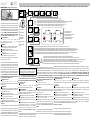 1
1
-
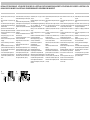 2
2
-
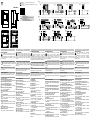 3
3
-
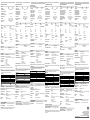 4
4


CARLO GAVAZZI EM24DINAV23XE1PFB Guía de instalación
- Tipo
- Guía de instalación
- Este manual también es adecuado para
en otros idiomas
- français: CARLO GAVAZZI EM24DINAV23XE1PFB Guide d'installation
- italiano: CARLO GAVAZZI EM24DINAV23XE1PFB Guida d'installazione
- English: CARLO GAVAZZI EM24DINAV23XE1PFB Installation guide
- Deutsch: CARLO GAVAZZI EM24DINAV23XE1PFB Installationsanleitung
- dansk: CARLO GAVAZZI EM24DINAV23XE1PFB Installationsvejledning
Artículos relacionados
-
CARLO GAVAZZI EM24DINAV21XW1EPFB El manual del propietario
-
-
CARLO GAVAZZI EM24DINAV23XM1SFA El manual del propietario
-
-
-
CARLO GAVAZZI EM2696AV63HR2S1XX Guía de instalación
-
-
-
-

