CARLO GAVAZZI EM24DINAV21XW1EPFB Manual de usuario
- Tipo
- Manual de usuario

EM24 W1
USER MANUAL
MANUALE D’USO
BETRIEBSANLEITUNG
MANUEL D’EMPLOI
MANUAL DE USUARIO
BRUGERMANUAL

EM24 W1 - Instruction manual | CARLO GAVAZZI Controls SpA
EM24 W1
Three-phase energy analyzer
USER MANUAL

3EM24 W1 - Instruction manual | CARLO GAVAZZI Controls SpA
Contents
EM24 W1 5
Description 5
Structure 5
EM24 W1 use 6
Introduction 6
Display 6
Working with the measurement/info menu 7
Working with the settings menu 7
Setting a parameter 7
Setting wireless M-Bus parameters 9
Testing wireless M-Bus communication 10
Measurement menu - measurement pages 11
Information Menu 12
General settings 13
Essential information 14
Easy connection 14
Average value calculation (dmd) 14
Frames 14
Security proles 16
Encryption key 16
Frontal LED 16
Frontal selector 16
Maintenance and disposal 17

4EM24 W1 - Instruction manual | CARLO GAVAZZI Controls SpAEM24 W1 - Instruction manual | CARLO GAVAZZI Controls SpA
Information property
Copyright © 2018, CARLO GAVAZZI Controls SpA
All rights reserved in all countries.
CARLO GAVAZZI Controls SpA reserves the right to apply modifications or make improvements to the relative documentation
without the obligation of advance notice.
Safety messages
The following section describes the warnings related to user and device safety included in this document:
NOTICE: indicates obligations that if not observed may lead to damage to the device.
CAUTION! Indicates a risky situation which, if not avoided, may cause data loss.
IMPORTANT: provides essential information on completing the task that should not be neglected.
General warnings
This manual is an integral part of the product and accompanies it for its entire working life. It should be consulted for all
situations tied to configuration, use and maintenance. For this reason, it should always be accessible to operators.
NOTICE: no one is authorized to open the analyzer. This operation is reserved exclusively for CARLO GAVAZZI technical
service personnel.
Protection may be impaired if the instrument is used in a manner not specified by the manufacturer.
Service and warranty
In the event of malfunction, fault, requests for information, contact the CARLO GAVAZZI branch or distributor in your country.
Installation and use of analyzers other than those indicated in the provided instructions void the warranty.
Download
This manual www.productselection.net/MANUALS/UK/EM24_im_use.pdf
Installation instruction - EM24 www.productselection.net/MANUALS/UK/EM24_im_inst.pdf
UCS software www.productselection.net/Download/UK/ucs.zip

5EM24 W1 - Instruction manual | CARLO GAVAZZI Controls SpAEM24 W1 - Instruction manual | CARLO GAVAZZI Controls SpA
EM24 W1
Introduction
Description
EM24 is a three-phase energy analyzer for DIN-rail mounting, with configuration joystick and LCD display.
The direct connection version (AV2) allows to measure up to 65 A, the CT connection version (AV5) allows to measure up to 34875 A by
means of current transformers (5 A secondary output).
The wireless M-Bus communication allows to transmit the collected data.
Structure
AV2 AV5
Part Description
ALCD display
BVoltage/current connections
CJoystick
DSelector with pin for MID seal (programming block)
ESMA connector (external antenna version)
FPins for MID seal (protection covers included)
GExternal antenna for wireless M-Bus communication
HSMA connector cable (2 m)

EM24 W1 - Instruction manual | CARLO GAVAZZI Controls SpA6EM24 W1 - Instruction manual | CARLO GAVAZZI Controls SpA
EM24 W1 use
Interface
Introduction
EM24 is organized in two menus:
• measurement and information menu: pages used to display the measurement pages, information relevant to the programmed parameters
and instrument firmware release
• settings menu: pages used to set parameters
Display
The display is divided into 3 lines.
Symbol Description
Displaying of phase-to-neutral system voltage
Displaying of phase-to-phase system voltage
Displaying of max values
Displaying of system variables
Displaying of dmd variables
EEEE
Overflow.
Note: in case of overflow of at least one current, hour
counter increase is disabled. The calculation of DMD
and the energy counters are calculated considering the
value of the measure in overflow as equal to the maxi-
mum managed by the instrument. “EEEE” in a single
phase variable automatically implies that the upper limit
of the related system variable has been exceeded, and
the indication of PF is forced to “1,000”.

7
EM24 W1 use
EM24 W1 - Instruction manual | CARLO GAVAZZI Controls SpAEM24 W1 - Instruction manual | CARLO GAVAZZI Controls SpA
Working with EM24 W1
Working with the measurement/info menu
Working with the settings menu
Setting a parameter
Example procedure: how to set Ct rAtio=20 and save changes.
Step Action Button
1 Power on the energy analyzer -
2 Press the joystick for at least 3 seconds
3 In the PASS? page, select the correct password (default 0)
4 Confirm operation
to next measurement page
to previous measurement page
to sengs menu
to previous info page to next info page
increase a parameter value
decrease a parameter value
edit/conrm
to previous page to next page

8
EM24 W1 use
EM24 W1 - Instruction manual | CARLO GAVAZZI Controls SpAEM24 W1 - Instruction manual | CARLO GAVAZZI Controls SpA
Step Action Button
5 Scroll pages until Ct rAtio
6 Enter the editing mode
7 Select 20
8 Confirm operation
9 Scroll pages until End
10 Confirm operation to exit

9
EM24 W1 use
EM24 W1 - Instruction manual | CARLO GAVAZZI Controls SpAEM24 W1 - Instruction manual | CARLO GAVAZZI Controls SpA
Wireless M-Bus communication setting
Setting wireless M-Bus parameters
Step Action Button
1 Press the button for at least 3 seconds
2 In the PASS? page, select the correct password (default 0)
3 Confirm operation
4 Scroll pages until ModE
5 Press the joystick to edit the parameter
6 Select the option
7 Confirm
8 Go to FrAME
9 Press the button to edit the parameter
10
Select the frame type according to the desired variables:
Variable Frame 1 Frame 2 Frame 3 Frame 4
Total imported active
energy
● ● ● ●
Total exported active
energy
●
Total imported reactive
energy
● ● ●
Total exported reactive
energy
● ● ●
Imported active power ● ● ●
Exported active power ●
Imported reactive power ● ●
Exported reactive power ● ●
Current L1 ●
Current L2 ●
Current L3 ●
Voltage L1-N ●
Voltage L2-N ●
Voltage L3-N ●
Supply frequency ●
Error flag ● ● ● ●
12 Confirm
13 Scroll pages until interVAL

10
EM24 W1 use
EM24 W1 - Instruction manual | CARLO GAVAZZI Controls SpAEM24 W1 - Instruction manual | CARLO GAVAZZI Controls SpA
Step Action Button
14 Press the button to edit the parameter
15 Select the option
16 Confirm
17 Scroll pages until EnCrYPt
18 Press the button to edit the parameter
19 Select the option
20 Confirm
21 Scroll pages until End
22 Confirm to exit
Testing wireless M-Bus communication
Step Action Button
1 Scroll Info pages until tr tESt
2 Press the button to force the communication
3 Verify if the master has received the message -

11
EM24 W1 use
EM24 W1 - Instruction manual | CARLO GAVAZZI Controls SpAEM24 W1 - Instruction manual | CARLO GAVAZZI Controls SpA
Menu description
Measurement menu - measurement pages
The displayed pages depend on the version and settings.
Page Displayed measurements Description
1
L1-L2-L3
VLNΣ
Hz
Phase sequence
System phase-neutral voltage
Frequency
2
L1-L2-L3
VLLΣ
Hz
Phase sequence
System phase-phase voltage
Frequency
3
Tot kWh (+)
WΣ dmd
WΣ dmd max
Total imported active energy
System active power dmd
System active power dmd max
4
kWh
A dmd max
PArt
Partial imported active energy
Maximum dmd current
5
Tot kvarh (+)
VAΣ dmd
VAΣ dmd max
Total imported reactive energy
System apparent power dmd
System apparent power dmd max
6
kvarh
VAΣ
PArt
Partial imported reactive energy
System apparent power
7
Total kvarh (-)
VAΣ dmd
VAΣ dmd max
Total exported reactive energy
System apparent power dmd
System apparent power dmd max
8
Total kWh (-)
WΣ dmd
WΣ dmd max
Total exported active energy
System active power dmd
System active power dmd max
9
Hours
WΣ
PFΣ
Total load operating hours
System active power
System power factor
10
Hours
VArΣ
PFΣ
Total load operating hours
System reactive power
System power factor
11
var L1
var L2
var L3
Phase 1 reactive power
Phase 2 reactive power
Phase 3 reactive power
12
VA L1
VA L2
VA L3
Phase 1 apparent power
Phase 2 apparent power
Phase 3 apparent power
13
PF L1
PF L2
PF L3
Phase 1 power factor
Phase 2 power factor
Phase 3 power factor
14
W L1
W L2
W L3
Phase 1 active power
Phase 2 active power
Phase 3 active power
15
A L1
A L2
A L3
Phase 1 current
Phase 2 current
Phase 3 current
16
V L1-2
V L2-3
V L3-1
Phase 1-phase 2 voltage
Phase 2-phase 3 voltage
Phase 3-phase 1 voltage
17
V L1
V L2
V L3
Phase 1 voltage
Phase 2 voltage
Phase 3 voltage

12
EM24 W1 use
EM24 W1 - Instruction manual | CARLO GAVAZZI Controls SpAEM24 W1 - Instruction manual | CARLO GAVAZZI Controls SpA
Information Menu
Page Page title Information displayed
1CoMM rEV Firmware revision (communication)
2 StAtuS Device status
3 ModE Transmission mode
4 FrAME Frame type
5 interVAL Transmission interval
6 EnCrYPt Encryption
7tr tESt
Transmission test by pressing the joystick
• transmission counter
• transmission feedback (tr)
8id nuM Identification number for wireless M-Bus communication
9CT ratio CT ratio
10 1P/2P/3P/3Pn
(2-3-4-wire)
System
Connection (2-3-4-wire)
11 Pulse LED pulse weight (kWh/kvarh per pulse)
12 ChEcKSuM FW checksum for MID certification
13 Year Firmware release
Year of production

13
EM24 W1 use
EM24 W1 - Instruction manual | CARLO GAVAZZI Controls SpAEM24 W1 - Instruction manual | CARLO GAVAZZI Controls SpA
General settings
The available settings depend on the version, the settings and the selector position.
Page title Sub-menu Description Values Default value
Cng PASS - Change password From 0 to 9999 0
MEASurE Measure type A
b
A
SELECtor SELEC. 1 Page displayed according to selector
position among the available pages for
each application (see”Frontal selector”
on page 16)
From 1 to 17 1
SELEC. 2 From 1 to 17 3
SELEC. 3 From 1 to 17 3
SELEC.LoC From 1 to 17 3
SYS - System 3P.n
1P
3P
Note: MID (PFA, PFB): not available
3P.n
Ct rAtio - Current transformer ratio (CT) AV5: from 1 to 6975 (non MID)
AV2: N/A
1
ModE - Transmission mode t1
C1
t1
FrAME Frame type 1
2
3
4
2
intErVAL Interval 10 s
30 s
1 m
5 m
15 m
30 m
60 m
1 m
EnCrYPt Encryption prole no
a
b
a
EnE t.rES Total counter reset no
yes
no
EnE P.rES Partial counter reset no
yes
no
rESEt dmd max Dmd calculation and dmd max reset no
yes
no
End - Exit and save - -
Note: OMS certification is valid with the following settings:
- Frame type: 2 or 3
- Communication interval: 30 s, 1 m or 5 m
- Encryption enabled (security profile A or B)

14
Essential information
EM24 W1 - Instruction manual | CARLO GAVAZZI Controls SpAEM24 W1 - Instruction manual | CARLO GAVAZZI Controls SpA
Essential information
Measurement management
Easy connection
If the “Measure” parameter is set to A (easy connection), for the calculation of the active energy the power is always integrated, both in the case of imported
and exported power . The current direction does not affect the measurement. If the “Measure” parameter is set to B (without easy connection), both the active
imported and exported are available.
Average value calculation (dmd)
The system calculates the average value of electrical variables in a set integration interval.
Dmd values are available on display only. The dmd interval is automatically set equal to the transmission interval and it is not synchronized with the transmission
interval.
Communication
Frames
The frames are packages of messages sent by EM24 containing the variables measured. The variables and their encoding included in the frame depend on the
type of frame selected:
Frame 1
Variable Data Format Engineering unit DIF
[hex]
VIF
[hex]
VIFE#1
[hex]
VIFE#2
[hex]
VIFE#3
[hex]
Total imported active energy 32 bit integer Wh*100 04 05
Error ag 8 bit integer 01 FD 17
Frame 2
Variable Data Format Engineering unit DIF
[hex]
VIF
[hex]
VIFE#1
[hex]
VIFE#2
[hex]
VIFE#3
[hex]
Total imported active
energy
32 bit integer Wh*100 04 05
Total imported reactive
energy
32 bit integer kVarh*0.1 04 FB 82 75
Total exported reactive
energy
32 bit integer kVarh*0.1 04 FB 82 F5 3C
Imported active power 32 bit integer Watt*0.1 04 2A
Error ag 8 bit integer 01 FD 17
Frame 3
Variable Data Format Engineering unit DIF
[hex]
VIF
[hex]
VIFE#1
[hex]
VIFE#2
[hex]
VIFE#3
[hex]
Total imported active
energy
32 bit integer Wh*100 04 05
Total imported reactive
energy
32 bit integer kVarh*0.1 04 FB 82 75
Total exported reactive
energy
32 bit integer kVarh*0.1 04 FB 82 F5 3C
Imported active power 32 bit integer Watt*0.1 04 2A
Imported reactive power 32 bit integer Var 04 FB 14
Exported reactive power 32 bit integer Var 04 FB 94 3C

15
Essential information
EM24 W1 - Instruction manual | CARLO GAVAZZI Controls SpAEM24 W1 - Instruction manual | CARLO GAVAZZI Controls SpA
Frame 3
Variable Data Format Engineering unit DIF
[hex]
VIF
[hex]
VIFE#1
[hex]
VIFE#2
[hex]
VIFE#3
[hex]
Current L1 32 bit integer Ampere*0.001 04 FD D9 FC 01
Current L2 32 bit integer Ampere*0.001 04 FD D9 FC 02
Current L3 32 bit integer Ampere*0.001 04 FD D9 FC 03
Voltage L1-N 32 bit integer Volt*0.1 04 FD C8 FC 01
Voltage L2-N 32 bit integer Volt*0.1 04 FD C8 FC 02
Voltage L3-N 32 bit integer Volt*0.1 04 FD C8 FC 03
Frequency 16 bit integer Hz*0.1 02 FB 2E
Error ag 8 bit integer 01 FD 17
Frame 4
Variable Data Format Engineering unit DIF
[hex]
VIF
[hex]
VIFE#1
[hex]
VIFE#2
[hex]
VIFE#3
[hex]
Total imported active
energy
32 bit integer Wh*100 04 05
Total exported active
energy
32 bit integer Wh*100 04 85 3C
Total imported reactive
energy
32 bit integer kVarh*0.1 04 FB 82 75
Total exported reactive
energy
32 bit integer kVarh*0.1 04 FB 82 F5 3C
Imported active power 32 bit integer Watt*0.1 04 2A
Exported active power 32 bit integer Watt*0.1 04 AA 3C
Imported reactive power 32 bit integer Var 04 FB 14
Exported reactive power 32 bit integer Var 04 FB 94 3C
Error ag 8 bit integer 01 FD 17
Notes:
• the values transmitted - energy, current, voltage, frequency - are instant values, while power values are the average values within the transmission interval
• “error flag” is a diagnostic variable used to communicate an overflow condition which makes the measured data invalid:
Bit Meaning Notes
8
[MSb]
7654321
[LSb]
1P system 3P system • N.A. (not available): the bit cannot be set because the relevant
measurement is not dened, bit = 0.
• Frequency out of range is set when occurs an overow or an under-
ow of the frequency measured by measuring module.
• In system 3P, monitored voltages are the L-N voltages referred to a
virtual neutral.
0 0 0 0 0 0 0 0 No error
00000001 V1N overow
0 0 0 0 0 0 1 0 N.A. V2N overow
00000100 N.A.V3N overow
00001000 I1 overow
00010000 N.A. I2 overow
00100000 N.A. I3 overow
0 1 0 0 0 0 0 0 Frequency out of range

EM24 W1 - Instruction manual | CARLO GAVAZZI Controls SpA16
Essential information
EM24 W1 - Instruction manual | CARLO GAVAZZI Controls SpA
Frame available according to the EM24 model:
Frame type “X” models “PFA” models “PFB” models
1 X X X
2 X X X
3 X X X
4 X X
rror ag
Encryption
To ensure data privacy and prevent data access by unauthorized parties, you can enable M-Bus wireless communication data encryption.
Security proles
Two security profiles are available:
• Security profile A (ENC-Mode 5)
• Security profile B (ENC-Mode 7)
Encryption key
The encryption key is uniquely associated with each device. The key is included in a sealed envelope contained in the package of EM24.
IMPORTANT: KEEP THE ENCRYPTION KEY. In case of loss, it is not possible to recover the key and the tool can be used only without cryptography.
Frontal LED and selector
Frontal LED
The frontal red LED flashes proportionally to the active imported energy consumption if the selector is in - 1 - 2 position, and to the reactive inductive
energy consumption in kvarh position. Any kind of negative (exported) energy will not be managed by the front LED.
Frontal selector
• Lock position: the frontal selector prevents from accessing the programming mode of measurement parameters.
• 1, 2, kvarh position: quick access to measuring pages. Each position is associated with one measuring page.
Note: in MID versions the position in sealed in Lock .

17
Maintenance and disposal
EM24 W1 - Instruction manual | CARLO GAVAZZI Controls SpAEM24 W1 - Instruction manual | CARLO GAVAZZI Controls SpA
Maintenance and disposal
Cleaning
Use a slightly dampened cloth to clean the display. Do not use abrasives or solvents.
Responsibility for disposal
The product must be disposed of at the relative recycling centers specified by the government or local public authorities. Correct disposal
and recycling will contribute to the prevention of potentially harmful consequences to the environment and persons.

EM24 W1 - User manual
2021-06 | Copyright © 2019
CARLO GAVAZZI Controls SpA
via Safforze, 8
32100 Belluno (BL) Italy
www.gavazziautomation.com
info: +39 0437 355811
fax: +39 0437 355880

EM24 W1
Analizzatore di energia trifase
MANUALE D’USO

20 EM24 W1 - Manuale d'istruzioni | CARLO GAVAZZI Controls SpA
Indice
EM24 W1 22
Descrizione 22
Struttura 22
Utilizzo di EM24 W1 23
Introduzione 23
Visualizzazione 23
Utilizzo del menu misure/informazioni 24
Utilizzo del menu impostazioni 24
Impostazione di un parametro 24
Impostazione dei parametri dell’M-Bus wireless 26
Prova della comunicazione dell’M-Bus wireless 27
Menu misure - pagine delle misure 28
Menu Informazioni 29
Impostazioni generali 30
Informazioni essenziali 31
Connessione facile 31
Calcolo del valore medio (dmd) 31
Frame 31
Proli di sicurezza 33
Chiave di crittograa 33
LED frontale 33
Selettore frontale 33
Manutenzione e smaltimento 34

21EM24 W1 - Manuale d'istruzioni | CARLO GAVAZZI Controls SpA
Proprietà delle informazioni
Copyright © 2019, CARLO GAVAZZI Controls SpA
Tutti i diritti riservati in tutti i paesi.
CARLO GAVAZZI Controls SpA si riserva il diritto di apportare modifiche o miglioramenti alla relativa documentazione senza
obbligo di preavviso.
Messaggi di sicurezza
Di seguito le segnalazioni legate alla sicurezza dell’utilizzatore e dell’apparecchio contenute in questo documento:
AVVISO: indica obblighi che se non ottemperati possono causare danni all’apparecchio.
ATTENZIONE! Indica una situazione rischiosa che se non evitata, può causare la perdita di dati.
IMPORTANTE: offre indicazioni essenziali al completamento del compito che non devono essere trascurate.
Avvertenze generali
Questo manuale è parte integrante del prodotto e accompagna il prodotto per tutta la sua vita. Deve essere consultato per
tutte le situazioni legate alla configurazione, all’uso e alla manutenzione. Per questo motivo deve essere sempre accessibile
agli operatori.
AVVISO: nessuno è autorizzato ad aprire l’analizzatore. TSolo il personale dell’assistenza tecnica CARLO GAVAZZI può
farlo. La protezione può essere compromessa se lo strumento viene usato in un modo non specificato dal costruttore.
Assistenza e garanzia
In caso di malfunzionamento, guasto, necessità informazioni o per acquistare componenti contattare la filiale CARLO GAVAZZI o
il distributore nel paese di appartenenza.
L’installazione e l’uso dell’analizzatore diversi da quanto indicato nelle istruzioni fornite invalidano la garanzia.
Download
Questo manuale www.productselection.net/MANUALS/UK/EM24_W1_im_use.pdf
Istruzioni per l’installazione - EM24 www.productselection.net/MANUALS/UK/EM24_W1_im_inst.pdf

22 EM24 W1 - Manuale d'istruzioni | CARLO GAVAZZI Controls SpA
EM24 W1
Introduzione
Descrizione
EM24 è un analizzatore di energia trifase per montaggio su guida DIN con joystick di configurazione e display LCD.
La versione con connessione diretta (AV2) consente di misurare fino a 65 A, mentre la versione con connessione da CT (AV5) consente di
misurare fino a 34875 A mediante trasformatori di corrente (uscita secondaria 5 A).
La comunicazione wireless M-Bus consente la trasmissione dei dati raccolti.
Struttura
AV2 AV5
Parte Descrizione
ADisplay LCD
BConnessioni tensione/corrente
CJoystick
DSelettore con pin per sigillo MID (blocco programmazione)
EConnettore SMA (versione con antenna esterna)
FPin per sigillo MID (coperture di protezione incluse)
GAntenna esterna per comunicazione M-Bus wireless
HCavo connettore SMA (2 m)

23EM24 W1 - Manuale d'istruzioni | CARLO GAVAZZI Controls SpA
Utilizzo di EM24 W1
Interfaccia
Introduzione
L’interfaccia di EM24 è organizzata in due menu:
• menu misure e informazioni: pagine utilizzate per visualizzare le pagine delle misure e informazioni relative ai parametri programmati e alla
release del firmware dello strumento
• menu impostazioni: pagine utilizzate per l’impostazione dei parametri
Visualizzazione
Il display è suddiviso in 3 righe.
Simbolo Descrizione
Visualizzazione della tensione di sistema fase-neutro
Visualizzazione della tensione di sistema fase-fase
Visualizzazione dei valori massimi
Visualizzazione delle variabili di sistema
Visualizzazione delle variabili dmd
EEEE
Overflow.
Nota: se almeno una corrente è in overflow, l’incremento
del contaore è inibito.
Il calcolo del DMD e i contatori di energia sono calcolati
considerando il valore della grandezza in overflow pari al
massimo gestito dallo strumento.
L’indicazione “EEEE” in una variabi le monofase implica
automaticamente la condizione di superamento del limite
superiore della relativa variabile di sistema, e l’indicazio-
ne del PF è forzata a “1.000”.

24
Utilizzo di EM24 W1
EM24 W1 - Manuale d'istruzioni | CARLO GAVAZZI Controls SpA
Utilizzo di EM24 W1
Utilizzo del menu misure/informazioni
Utilizzo del menu impostazioni
Impostazione di un parametro
Esempio di procedura: come impostare Ct rAtio=20 e salvare le modifiche.
Passaggio Azione Pulsante
1 Accendere l’analizzatore di energia -
2 Premere il joystick per almeno 3 secondi
3 Nella pagina PASS?, selezionare la password corretta (la password predefinita è 0)
4 Confermare l’operazione
alla pagina misure seguente
alla pagina misure precedente
al menu impostazioni
alla pagina informazioni precedente alla pagina informazioni seguente
aumenta il valore di un parametro
diminuisce il valore di un parametro
modica/conferma
alla pagina precedente alla pagina seguente

25
Utilizzo di EM24 W1
EM24 W1 - Manuale d'istruzioni | CARLO GAVAZZI Controls SpA
Passaggio Azione Pulsante
5 Scorrere le pagine fino a visualizzare Ct rAtio
6 Entrare in modalità modifica
7 Selezionare 20
8 Confermare l’operazione
9 Scorrere le pagine fino a visualizzare End
10 Confermare l’operazione per uscire

26
Utilizzo di EM24 W1
EM24 W1 - Manuale d'istruzioni | CARLO GAVAZZI Controls SpA
Impostazione della comunicazione M-Bus Wireless
Impostazione dei parametri dell’M-Bus wireless
Passaggio Azione Pulsante
1 Premere il pulsante per almeno 3 secondi
2 Nella pagina PASS?, selezionare la password corretta (la password predefinita è 0)
3 Confermare l’operazione
4 Scorrere le pagine fino a visualizzare ModE
5 Premere il joystick per modificare il parametro
6 Selezionare l’opzione
7 Confermare
8 Passare a FrAME
9 Premere il pulsante per modificare il parametro
10
Selezionare il tipo di frame in base alle variabili desiderate:
Variabile Frame 1 Frame 2 Frame 3 Frame 4
Energia attiva importata
totale
● ● ● ●
Esportazione energia
attiva
●
Energia reattiva importata
totale
● ● ●
Energia reattiva esportata
totale
● ● ●
Potenza attiva importata ● ● ●
Potenza attiva esportata ●
Potenza reattiva importata ● ●
Potenza reattiva esportata ● ●
Corrente L1 ●
Corrente L2 ●
Corrente L3 ●
Tensione L1-N ●
Tensione L2-N ●
Tensione L3-N ●
Frequenza di alimenta-
zione
●
Flag errore ● ● ● ●
12 Confermare

27
Utilizzo di EM24 W1
EM24 W1 - Manuale d'istruzioni | CARLO GAVAZZI Controls SpA
Passaggio Azione Pulsante
13 Scorrere le pagine fino a visualizzare interVAL
14 Premere il pulsante per modificare il parametro
15 Selezionare l’opzione
16 Confermare
17 Scorrere le pagine fino a visualizzare EnCrYPt
18 Premere il pulsante per modificare il parametro
19 Selezionare l’opzione
20 Confermare
21 Scorrere le pagine fino a visualizzare End
22 Confermare per uscire
Prova della comunicazione dell’M-Bus wireless
Passaggio Azione Pulsante
1 Scorrere le pagine delle Informazioni fino a visualizzare tr tESt
2 Premere il pulsante per forzare la comunicazione
3 verificare se il master ha ricevuto il messaggio -

28
Utilizzo di EM24 W1
EM24 W1 - Manuale d'istruzioni | CARLO GAVAZZI Controls SpA
Descrizione dei menu
Menu misure - pagine delle misure
Le pagine visualizzate dipendono dalla versione e dalle impostazioni.
Pagina Misure visualizzate Descrizione
1
L1-L2-L3
VLNΣ
Hz
Sequenza fasi
Tensione fase-neutro sistema
Frequenza
2
L1-L2-L3
VLLΣ
Hz
Sequenza fasi
Tensione fase-fase sistema
Frequenza
3
Tot kWh (+)
Dmd WΣ
Dmd WΣ massima
Energia attiva importata totale
Potenza attiva DMD di sistema
Potenza attiva DMD di sistema massima
4
kWh
Dmd A massima
PArt
Energia attiva importata parziale
Corrente DMD massima
5
Tot kvarh (+)
Dmd VAΣ
Dmd VAΣ massima
Energia reattiva importata totale
Potenza apparente DMD di sistema
Potenza apparente DMD di sistema massima
6
kvarh
VAΣ
PArt
Energia reattiva importata parziale
Potenza apparente sistema
7
Kvarh totale (-)
Dmd VAΣ
Dmd VAΣ massima
Energia reattiva esportata totale
Potenza apparente DMD di sistema
Potenza apparente DMD di sistema massima
8
KWh totale (-)
Dmd WΣ
Dmd WΣ massima
Energia attiva esportata totale
Potenza attiva DMD di sistema
Potenza attiva DMD di sistema massima
9
Ore
WΣ
PFΣ
Totale ore di funzionamento del carico
Potenza attiva sistema
Fattore di potenza di sistema
10
Ore
VArΣ
PFΣ
Totale ore di funzionamento del carico
Potenza reattiva sistema
Fattore di potenza di sistema
11
var L1
var L2
var L3
Potenza reattiva fase 1
Potenza reattiva fase 2
Potenza reattiva fase 3
12
VA L1
VA L2
VA L3
Potenza apparente fase 1
Potenza apparente fase 2
Potenza apparente fase 3
13
PF L1
PF L2
PF L3
Fattore di potenza fase 1
Fattore di potenza fase 2
Fattore di potenza fase 3
14
W L1
W L2
W L3
Potenza attiva fase 1
Potenza attiva fase 2
Potenza attiva fase 3
15
A L1
A L2
A L3
Corrente fase 1
Corrente fase 2
Corrente fase 3
16
V L1-2
V L2-3
V L3-1
Tensione fase 1-fase 2
Tensione fase 2-fase 3
Tensione fase 3-fase 1
17
V L1
V L2
V L3
Tensione fase 1
Tensione fase 2
Tensione fase 3

29
Utilizzo di EM24 W1
EM24 W1 - Manuale d'istruzioni | CARLO GAVAZZI Controls SpA
Menu Informazioni
Pagina Titolo pagina Informazioni visualizzate
1CoMM rEV Revisione firmware (comunicazione)
2 StAtuS Stato del dispositivo
3 ModE Modalità di trasmissione
4 FrAME Tipo frame
5 interVAL Intervallo di trasmissione
6 EnCrYPt Crittografia
7tr tESt
Test di trasmissione premendo il joystick
• contatore delle trasmissioni
• feedback trasmissione (tr)
8id nuM Numero di identificazione per comunicazione M-Bus wireless
9CT rAtio Rapporto CT
10 1P/2P/3P/3Pn
(2-3-4 fili)
Sistema
Connessione (2-3-4 fili)
11 Pulse Peso impulso LED (kWh/kvarh per ciascun impulso)
12 Checksum Checksum FW per certificazione MID
13 Year Release firmware
Anno di produzione

30
Utilizzo di EM24 W1
EM24 W1 - Manuale d'istruzioni | CARLO GAVAZZI Controls SpA
Impostazioni generali
Le impostazioni disponibili dipendono dalla versione, dalle impostazioni e dalla posizione del selettore.
Titolo pa-
gina
Sottomenu Descrizione Valori Valore prede-
nito
Cng PASS - Cambio password Da 0 a 9999 0
MEASurE Tipo di misura A
b
A
SELECtor SELEC. 1 Pagina visualizzata in base alla posizio-
ne del selettore, tra quelle disponibili per
ciascuna applicazione (vedere”Selettore
frontale” a pagina 33)
Da 1 a 17 1
SELEC. 2 Da 1 a 17 3
SELEC. 3 Da 1 a 17 3
SELEC.LoC Da 1 a 17 3
SYS - Sistema 3P.n
1P
3P
Nota: MID (PFA, PFB): non disponibile
3P.n
Ct rAtio - Rapporto trasformatore corrente (CT) AV5: da 1 a 6975 (non MID)
AV2: N/A
1
ModE - Modalità di trasmissione t1
C1
t1
FrAME Tipo frame 1
2
3
4
2
intErVAL Intervallo 10 s
30 s
1 m
5 m
15 m
30 m
60 m
1 m
EnCrYPt Prolo crittograa no
a
b
a
EnE t.rES Azzeramento contatore totale no
Si
no
EnE P.rES Azzeramento contatore parziale no
Si
no
rESEt dmd max Azzeramento del calcolo della dmd e
della dmd massima
no
Si
no
End - Uscita e salvataggio - -
Nota: la certificazione OMS è valida con le seguenti impostazioni:
- Tipo frame: 2 o 3
- Intervallo di comunicazione: 30 s, 1 m o 5 m
- Crittografia abilitata (profilo sicurezza A o B)

31
Informazioni essenziali
EM24 W1 - Manuale d'istruzioni | CARLO GAVAZZI Controls SpA
Informazioni essenziali
Gestione delle misure
Connessione facile
Se il parametro “Measure” è impostato su A (connessione facile), per il calcolo dell’energia attiva la potenza è sempre integrata, sia nel caso della potenza
importata che in quello della potenza esportata. La direzione della corrente non influisce sulla misura. Se il parametro “Measure” è impostato su B (senza
connessione facile), sono disponibili sia la potenza attiva importata che quella esportata.
Calcolo del valore medio (dmd)
Il sistema calcola il valore medio delle variabili elettriche in un intervallo di integrazione definito.
I valori della potenza dmd posso essere soltanto visualizzati a display. L’intervallo per il calcolo della potenza dmd viene impostato automaticamente allo stesso
valore dell’intervallo di trasmissione e non è sincronizzato con l’intervallo di trasmissione.
Comunicazione
Frame
I frame sono pacchetti di messaggi inviati dall’EM24 contenenti le variabili misurate. Le variabili e la relativa codifica incluse nel frame dipendono dal tipo di
frame selezionato:
Frame 1
Variabile Formato Dati Unità ingegneristica DIF
[hex]
VIF
[hex]
VIFE#1
[hex]
VIFE#2
[hex]
VIFE#3
[hex]
Energia attiva importata
totale
32 bit intero Wh*100 04 05
Flag errore 8 bit intero 01 FD 17
Frame 2
Variabile Formato Dati Unità ingegneristica DIF
[hex]
VIF
[hex]
VIFE#1
[hex]
VIFE#2
[hex]
VIFE#3
[hex]
Energia attiva importata
totale
32 bit intero Wh*100 04 05
Energia reattiva importata
totale
32 bit intero kVarh*0.1 04 FB 82 75
Energia reattiva esportata
totale
32 bit intero kVarh*0.1 04 FB 82 F5 3C
Potenza attiva importata 32 bit intero Watt*0.1 04 2A
Flag errore 8 bit intero 01 FD 17
Frame 3
Variabile Formato Dati Unità ingegneristica DIF
[hex]
VIF
[hex]
VIFE#1
[hex]
VIFE#2
[hex]
VIFE#3
[hex]
Energia attiva importata
totale
32 bit intero Wh*100 04 05
Energia reattiva importata
totale
32 bit intero kVarh*0.1 04 FB 82 75
Energia reattiva esportata
totale
32 bit intero kVarh*0.1 04 FB 82 F5 3C
Potenza attiva importata 32 bit intero Watt*0.1 04 2A
Potenza reattiva importata 32 bit intero Var 04 FB 14
Potenza reattiva esportata 32 bit intero Var 04 FB 94 3C

32
Informazioni essenziali
EM24 W1 - Manuale d'istruzioni | CARLO GAVAZZI Controls SpA
Frame 3
Variabile Formato Dati Unità ingegneristica DIF
[hex]
VIF
[hex]
VIFE#1
[hex]
VIFE#2
[hex]
VIFE#3
[hex]
Corrente L1 32 bit intero Ampere*0.001 04 FD D9 FC 01
Corrente L2 32 bit intero Ampere*0.001 04 FD D9 FC 02
Corrente L3 32 bit intero Ampere*0.001 04 FD D9 FC 03
Tensione L1-N 32 bit intero Volt*0.1 04 FD C8 FC 01
Tensione L2-N 32 bit intero Volt*0.1 04 FD C8 FC 02
Tensione L3-N 32 bit intero Volt*0.1 04 FD C8 FC 03
Frequenza 16 bit intero Hz*0.1 02 FB 2E
Flag errore 8 bit intero 01 FD 17
Frame 4
Variabile Formato Dati Unità ingegneristica DIF
[hex]
VIF
[hex]
VIFE#1
[hex]
VIFE#2
[hex]
VIFE#3
[hex]
Energia attiva importata
totale
32 bit intero Wh*100 04 05
Energia attiva esportata
totale
32 bit intero Wh*100 04 85 3C
Energia reattiva importata
totale
32 bit intero kVarh*0.1 04 FB 82 75
Energia reattiva esportata
totale
32 bit intero kVarh*0.1 04 FB 82 F5 3C
Potenza attiva importata 32 bit intero Watt*0.1 04 2A
Potenza attiva esportata 32 bit intero Watt*0.1 04 AA 3C
Potenza reattiva importata 32 bit intero Var 04 FB 14
Potenza reattiva esportata 32 bit intero Var 04 FB 94 3C
Flag errore 8 bit intero 01 FD 17
Note:
• I valori trasmessi - energia, corrente, tensione, frequenza - sono valori istantanei, mentre i valori relativi alla potenza sono valori medi per l’intervallo di tra-
smissione.
• “flag error” è una variabile diagnostica utilizzata per comunicare una condizione di superamento del limite superiore che invalida i dati misurati:
Bit Signicato Note
8
[MSb]
7654321
[LSb]
Sistema 1P Sistema 3P • N.A. (non disponibile): il bit non può essere impostato perché la
relativa misura non è denita, bit = 0.
• Frequenza fuori range viene impostato quando si verica un
superamento del limite superiore o inferiore delle frequenza misurata
dal modulo di misura.
• Nel sistema 3P, le tensioni monitorate sono le tensioni L-N riferite al
neutro virtuale.
0 0 0 0 0 0 0 0 Nessun errore
00000001 Overow V1N
0 0 0 0 0 0 1 0 N.A. Overow
V2N
00000100 N.A. Overow
V3N
00001000 Overow I1
00010000 N.A. Overow I2
00100000 N.A. Overow I3
0 1 0 0 0 0 0 0 Frequenza fuori range
Frame disponibili a seconda del modello di EM24:
Tipo frame Modelli “X” Modelli “PFA” Modelli “PFB”
1 X X X
2 X X X
3 X X X
4 X X

33
Informazioni essenziali
EM24 W1 - Manuale d'istruzioni | CARLO GAVAZZI Controls SpA
Flag errore
Crittografia
Per garantire la riservatezza dei datti e impedirne l’accesso da parte di soggetti non autorizzati, è possibile abilitare la crittografia dei dati della comunicazione
su M-Bus wireless.
Proli di sicurezza
Sono disponibili due profili di sicurezza:
• Profilo si sicurezza A (ENC-Mode 5)
• Profilo si sicurezza B (ENC-Mode 7)
Chiave di crittograa
La chiave di crittografia è univocamente associata a ciascun dispositivo. La chiave è inclusa in una busta sigillata contenuta nella confezione dell’EM24.
IMPORTANTE: CONSERVARE CON CURA LA CHIAVE DI CRITTOGRAFIA. In caso di smarrimento, non è possibile recuperare la chiave, e lo strumento
può essere utilizzato soltanto senza crittografia.
LED frontale e selettore
LED frontale
Il LED frontale rosso lampeggia proporzionalmente al consumo di energia attiva importata se il selettore è in posizione - 1 - 2, e al consumo di energia
reattiva induttiva nella posizione kvarh . Il LED frontale non gestisce alcun tipo di energia negativa (esportata).
Selettore frontale
• Posizione Lock : il selettore frontale impedisce l’accesso alla modalità di programmazione dei parametri di misura.
• Posizione 1, 2, kvarh : accesso rapido alle pagine delle misure. Ciascuna posizione è associata a una pagina di misurazione.
Nota: nelle versioni MID è sigillata su Lock .

34
Manutenzione e smaltimento
EM24 W1 - Manuale d'istruzioni | CARLO GAVAZZI Controls SpA
Manutenzione e smaltimento
Pulizia
Utilizzare un panno leggermente inumidito per pulire il display. Non utilizzare abrasivi o solventi.
Responsabilità dello smaltimento
Il prodotto deve essere smaltito presso i relativi centri di riciclaggio specificati dal governo o dalle autorità pubbliche locali. Uno smaltimento
e un riciclaggio appropriati contribuiranno a prevenire potenziali conseguenze dannose per l’ambiente e le persone.

EM24 W1 - Manuale d'uso
2021-06 | Copyright © 2019
CARLO GAVAZZI Controls SpA
via Safforze, 8
32100 Belluno (BL) Italia
www.gavazziautomation.com
info: +39 0437 355811
fax: +39 0437 355880

EM24 W1 - Bedienungsanleitung | CARLO GAVAZZI Controls SpA
EM24 W1
Dreiphasen-Energieanalysator
BETRIEBSANLEITUNG

37EM24 W1 - Bedienungsanleitung | CARLO GAVAZZI Controls SpA
Inhaltsverzeichnis
EM24 W1 39
Beschreibung 39
Struktur 39
Benutzung des EM24 W1 40
Einleitung 40
Anzeige 40
Arbeiten mit dem Messungs-/Infomenü 41
Arbeiten mit dem Einstellungsmenü 41
Einstellen eines Parameters 41
Einstellen von Parametern des drahtlosen M-Bus 43
Testen der drahtlosen M-Bus-Kommunikation 44
Messungsmenü - Messungsseiten 45
Informationsmenü 46
Allgemeine Einstellungen 47
Wichtige Informationen 48
Einfacher Anschluss 48
Mittelwertberechnung (dmd) 48
Frames 48
Sicherheitsprole 50
Verschlüsselungsschlüssel 50
Front-LED 50
Vorderer Wahlschalter 50
Instandhaltung und Entsorgung 51

38 EM24 W1 - Bedienungsanleitung | CARLO GAVAZZI Controls SpAEM24 W1 - Bedienungsanleitung | CARLO GAVAZZI Controls SpA
Information über Eigentumsrechte
Copyright © 2019 CARLO GAVAZZI Controls SpA
Alle Rechte vorbehalten in allen Ländern.
CARLO GAVAZZI Controls SpA behält sich das Recht vor, ohne vorherige Ankündigung Änderungen oder Verbesserungen in der
entsprechenden Dokumentation vorzunehmen.
Sicherheitshinweise
Der folgende Abschnitt beschreibt die in diesem Dokument enthaltenen Warnungen in Bezug auf Benutzer- und Gerätesicherheit:
HINWEIS: Bezeichnet Bedienungsregeln, deren Nichtbeachtung zu Schäden am Gerät führen können.
VORSICHT! Bezeichnet eine riskante Situation, die Datenverlust verursachen kann, wenn sie nicht vermieden
wird.
WICHTIG: Bietet wesentliche Informationen zur Erledigung einer Aufgabe, die nicht vernachlässigt werden sollte.
Allgemeine Warnungen
Diese Anleitung ist ein integraler Bestandteil des Produkts und verbleibt bei ihm für seine gesamte Lebensdauer. Sie sollte
in allen Situationen betreffend Konfiguration, Gebrauch und Instandhaltung zu Rate gezogen werden. Deshalb sollte sie
dem Benutzer jederzeit zugänglich sein.
HINWEIS: Niemand ist autorisiert, das Analysator zu öffnen. Diese Operation ist ausschließlich dem technischen
Kundendienstpersonal von CARLO GAVAZZI vorbehalten.
Die Schutzfunktion kann beeinträchtigt werden, wenn das Instrument anders als vom Hersteller vorgesehen benutzt wird.
Kundendienst und Garantie
Bei Störungen oder Fehlern bzw. wenn Sie Auskünfte benötigen, wenden Sie sich bitte an die Niederlassung von CARLO GAVAZZI
oder den zuständigen Vertriebspartner in Ihrem Land.
Installation und Gebrauch von Analysatoren abweichend von der Beschreibung in der mitgelieferten Anleitung macht die Garantie
ungültig.
Download
Diese Anleitung www.productselection.net/MANUALS/UK/EM24_im_use.pdf
Installationsanleitung - EM24 www.productselection.net/MANUALS/UK/EM24_im_inst.pdf
UCS-Software www.productselection.net/Download/UK/ucs.zip

39EM24 W1 - Bedienungsanleitung | CARLO GAVAZZI Controls SpAEM24 W1 - Bedienungsanleitung | CARLO GAVAZZI Controls SpA
EM24 W1
Einleitung
Beschreibung
EM24 ist ein Drei-Phasen-Energieanalysator für DIN-Schienenmontage mit Konfigurationsjoystick und LCD-Anzeige.
Die Ausführung mit direktem Anschluss (AV2) ermöglicht die Messung bis zu 65 A, während die CT-Anschlussversion (AV5) die Messung bis
zu 34875 A mit Stromwandlern (5 A Sekundärausgang) erlaubt.
Die drahtlose M-Bus-Kommunikation erlaubt die Übertragung der gesammelten Daten.
Struktur
AV2 AV5
Teil Beschreibung
ALCD-Anzeige
BSpannungs-/Stromverbindungen
CJoystick
DWahlschalter mit Stift für MID-Versiegelung (Programmierblock)
ESMA-Anschluss (Version mit externer Antenne)
FStifte für MID-Versiegelung (Schutzabdeckungen inbegriffen)
GExterne Antenne für drahtlose M-Bus-Kommunikation
HSMA-Anschluss-Kabel (2 m)

EM24 W1 - Bedienungsanleitung | CARLO GAVAZZI Controls SpA40 EM24 W1 - Bedienungsanleitung | CARLO GAVAZZI Controls SpA
Benutzung des EM24 W1
Schnittstelle
Einleitung
Der EM24 bietet zwei Menüs an:
• Messungs- und Informationsmenü: Die Seiten zeigen Messungsseiten, Informationen über die programmierten Parameter und Firmware-
Release des Geräts an
• Einstellungsmenü: Die Seiten dienen für Parametereinstellungen
Anzeige
Die Anzeige ist in 3 Zeilen unterteilt.
Symbol Beschreibung
Anzeige der Phasen-Nullleiter-Systemspannung
Anzeige der Phasen-Phasen-Systemspannung
Anzeige der MAX-Werte
Anzeige der Systemvariablen
Anzeige der DMD Variablen
EEEE
Überlauf.
Hinweis: Bei einem Überlauf von mindestens einem
Strom wird die Erhöhung des Stundenzählers deakti-
viert. Die Berechnung von DMD und den Stromzählern
erfolgt unter Berücksichtigung des Messwertes im Über-
lauf als gleich dem vom Gerät verwalteten Maximum.
„EEEE” in einer Einphasen-Variable deutet automatisch
auf die Überschreitung der Obergrenze der relevanten
Systemvariable hin, und die PF-Angabe wird zu „1,000”
gezwungen.

41
Benutzung des EM24 W1
EM24 W1 - Bedienungsanleitung | CARLO GAVAZZI Controls SpAEM24 W1 - Bedienungsanleitung | CARLO GAVAZZI Controls SpA
Arbeiten mit EM24 W1
Arbeiten mit dem Messungs-/Infomenü
Arbeiten mit dem Einstellungsmenü
Einstellen eines Parameters
Beispielprozedur: Wie Ct rAtio=20 gesetzt und die Änderung gespeichert wird.
Schritt Aktion Taste
1 Energieanalysator einschalten -
2 Joystick für mindestens 3 Sekunden gedrückt halten
3 Auf der Seite PASS? das richtige Passwort eingeben (Standard 0)
4 Operation bestätigen
zur nächsten Messungsseite
zur vorherigen Messungsseite
zum Einstellungsmenü
zur vorherigen Infoseite zur nächsten Infoseite
Parameterwert erhöhen
Parameterwert verringern
Bearbeiten/Bestägen
zur vorherigen Seite zur nächsten Seite

42
Benutzung des EM24 W1
EM24 W1 - Bedienungsanleitung | CARLO GAVAZZI Controls SpAEM24 W1 - Bedienungsanleitung | CARLO GAVAZZI Controls SpA
Schritt Aktion Taste
5 Seiten scrollen bis Ct rAtio
6 Gelangen Sie in den Bearbeitungsmodus
7 20 auswählen
8 Operation bestätigen
9Seiten scrollen bis End
10 Operation bestätigen zum Beenden

43
Benutzung des EM24 W1
EM24 W1 - Bedienungsanleitung | CARLO GAVAZZI Controls SpAEM24 W1 - Bedienungsanleitung | CARLO GAVAZZI Controls SpA
Drahtloser M-Bus Kommunikationseinstellung
Einstellen von Parametern des drahtlosen M-Bus
Schritt Aktion Taste
1 Die Taste für mindestens 3 Sekunden gedrückt halten
2 Auf der Seite PASS? das richtige Passwort eingeben (Standard 0)
3 Operation bestätigen
4 Seiten scrollen bis ModE
5 Zum Editieren des Parameters den Joystick drücken
6 Option auswählen
7 Bestätigen
8 Gehe zu FrAME
9 Zum Editieren des Parameters die Taste drücken
10
Frame-Typ gemäß den gewünschten Variablen auswählen:
Variable Frame 1 Frame 2 Frame 3 Frame 4
Importierte Wirkenergie
gesamt
●●●●
Exportierte Wirkenergie ●
Importierte Blindenergie
gesamt
●●●
Exportierte Blindenergie
gesamt
●●●
Importierte Wirkleistung ●●●
Exportierte Wirkleistung ●
Importierte Blindleistung ● ●
Exportierte Blindleistung ● ●
Strom L1 ●
Strom L2 ●
Strom L3 ●
Spannung L1-N ●
Spannung L2-N ●
Spannung L3-N ●
Versorgungsfrequenz ●
Fehlerflagge ●●●●
12 Bestätigen

44
Benutzung des EM24 W1
EM24 W1 - Bedienungsanleitung | CARLO GAVAZZI Controls SpAEM24 W1 - Bedienungsanleitung | CARLO GAVAZZI Controls SpA
Schritt Aktion Taste
13 Seiten scrollen bis interVAL
14 Zum Editieren des Parameters die Taste drücken
15 Option auswählen
16 Bestätigen
17 Seiten scrollen bis EnCrYPt
18 Zum Editieren des Parameters die Taste drücken
19 Option auswählen
20 Bestätigen
21 Seiten scrollen bis End
22 Beenden bestätigen
Testen der drahtlosen M-Bus-Kommunikation
Schritt Aktion Taste
1 Seiten scrollen bis tr tESt
2 Zum Erzwingen der Kommunikation die Taste drücken
3 Verifizieren, ob der Master die Mitteilung erhalten hat -

45
Benutzung des EM24 W1
EM24 W1 - Bedienungsanleitung | CARLO GAVAZZI Controls SpAEM24 W1 - Bedienungsanleitung | CARLO GAVAZZI Controls SpA
Beschreibung der Menüs
Messungsmenü - Messungsseiten
Die angezeigten Seiten hängen von der Version und den Einstellungen ab.
Seite Angezeigte Messungen Beschreibung
1
L1-L2-L3
VLNΣ
Hz
Phasensequenz
System Phase-Nullleiter-Spannung
Frequenz
2
L1-L2-L3
VLLΣ
Hz
Phasensequenz
System Phase-Phase-Spannung
Frequenz
3
Gesamt kWh (+)
WΣ DMD
WΣ DMD max
Importierte Wirkenergie gesamt
System-Wirkleistung DMD
System-Wirkleistung DMD max.
4
kWh
A DMD max
Teil
Importierte Wirkenergie partiell
Maximalstrom DMD
5
Gesamt kvarh (+)
VAΣ DMD
VAΣ DMD max
Importierte Blindenergie gesamt
System-Scheinleistung DMD
System-Scheinleistung DMD max.
6
kvarh
VAΣ
Teil
Importierte Blindenergie partiell
System-Scheinleistung
7
Gesamt kvarh (-)
VAΣ DMD
VAΣ DMD max
Exportierte Blindenergie gesamt
System-Scheinleistung DMD
System-Scheinleistung DMD max.
8
Gesamt kWh (-)
WΣ DMD
WΣ DMD max
Total exported reactive energy
System apparent power dmd
System apparent power dmd max
9
Stunden
WΣ
PFΣ
Gesamt-Betriebsstunden unter Last
System-Wirkleistung
System-Leistungsfaktor
10
Stunden
VArΣ
PFΣ
Gesamt-Betriebsstunden unter Last
System-Blindleistung
System-Leistungsfaktor
11
var L1
var L2
var L3
Blindleistung Phase 1
Blindleistung Phase 2
Blindleistung Phase 3
12
VA L1
VA L2
VA L3
Scheinleistung Phase 1
Scheinleistung Phase 2
Scheinleistung Phase 3
13
PF L1
PF L2
PF L3
Leistungsfaktor Phase 1
Leistungsfaktor Phase 2
Leistungsfaktor Phase 3
14
W L1
W L2
W L3
Wirkleistung Phase 1
Wirkleistung Phase 2
Wirkleistung Phase 3
15
A L1
A L2
A L3
Strom Phase 1
Strom Phase 2
Strom Phase 3
16
V L1-2
V L2-3
V L3-1
Spannung Phase 1-Phase 2
Spannung Phase 2-Phase 3
Spannung Phase 3-Phase 1
17
V L1
V L2
V L3
Spannung Phase 1
Spannung Phase 2
Spannung Phase 3

46
Benutzung des EM24 W1
EM24 W1 - Bedienungsanleitung | CARLO GAVAZZI Controls SpAEM24 W1 - Bedienungsanleitung | CARLO GAVAZZI Controls SpA
Informationsmenü
Seite Seitentitel Angezeigte Information
1CoMM rEV Firmware-Revision (Kommunikation)
2 StAtuS Gerätestatus
3 ModE Übertragungsmodus
4 FrAME Frame-Typ
5 interVAL Übertragungsintervall
6 EnCrYPt Verschlüsselung
7tr tESt
Übertragungstest durch Drücken des Joysticks
• Übertragungszähler
• Übertragungsrückmeldung (tr)
8id nuM Identifikationsnummer für drahtlose M-Bus-Kommunikation
9CT-Ratio CT-Ratio
10 1P/2P/3P/3Pn
(2-3-4-Draht)
System
Anschluss (2-3-4-Draht)
11 Pulse LED Impulsgewicht (kWh/kvarh pro Impuls)
12 ChEcKSuM FW-Prüfsumme für MID-Zertifizierung
13 Year Firmware-Release
Herstellungsjahr

47
Benutzung des EM24 W1
EM24 W1 - Bedienungsanleitung | CARLO GAVAZZI Controls SpAEM24 W1 - Bedienungsanleitung | CARLO GAVAZZI Controls SpA
Allgemeine Einstellungen
Die verfügbaren Einstellungen hängen von der Version, den Einstellungen und der Wahlschalterposition ab.
Seitentitel Untermenü Beschreibung Werte Standardwert
Cng PASS - Passwort ändern Von 0 bis 9999 0
MEASurE Messungstyp A
b
A
SELECtor SELEC. 1 Die Seite wird nach Stellung des Wahl-
schalters unter den verfügbaren Seiten
für jede Anwendung angezeigt (siehe
„Vorderer Wahlschalter“ auf Seite 50)
Von 1 bis 17 1
SELEC. 2 Von 1 bis 17 3
SELEC. 3 Von 1 bis 17 3
SELEC.LoC Von 1 bis 17 3
SYS - System 3P.n
1P
3P
Hinweis: MID (PFA, PFB): nicht verfügbar
3P.n
Ct rAtio - Stromwandlerverhältnis (CT) AV5: von 1 bis 6975 (nicht-MID)
AV2: N/V
1
ModE - Übertragungsmodus t1
C1
t1
FrAME Frame-Typ 1
2
3
4
2
intErVAL Intervall 10 s
30 s
1 min
5 min
15 min
30 min
60 min
1 min
EnCrYPt Verschlüsselungsprol Nein
a
b
Verfügbar
EnE t.rES Gesamtzähler zurücksetzen Nein
Ja
Nein
EnE P.rES Partialzähler zurücksetzen Nein
Ja
Nein
rESEt dmd max DMD-Berechnung und DMD MAX
zurücksetzen
Nein
Ja
Nein
End - Beenden und speichern - -
Hinweis: OMS-Zertifikation ist gültig mit den folgenden Einstellungen:
- Frame-Typ: 2 oder 3
- Kommunikationsintervall: 30 s, 1 min oder 5 min
- Verschlüsselung aktiviert (Sicherheitsprofil A oder B)

48
Wichtige Informationen
EM24 W1 - Bedienungsanleitung | CARLO GAVAZZI Controls SpAEM24 W1 - Bedienungsanleitung | CARLO GAVAZZI Controls SpA
Wichtige Informationen
Verwaltung der Messungen
Einfacher Anschluss
Wenn der “Messung”-Parameter auf A gesetzt ist (einfacher Anschluss), wird die Leistung für die Berechnung der Wirkenergie immer integriert, sowohl bei
der importierten als auch exportierten Leistung. Die Stromrichtung beeinträchtigt nicht die Messung. Wenn der “Messung”-Parameter auf B gesetzt ist (ohne
einfachen Anschluss), sind sowohl die importierte als auch exportierte Wirkenergie verfügbar.
Mittelwertberechnung (dmd)
Das System berechnet Mittelwerte von elektrischen Messgrößen in einem eingestellten Integrationsintervall.
DMD-Werte sind nur auf der Anzeige verfügbar. Das DMD-Intervall wird automatisch gleich dem Übertragungsintervall gesetzt und ist nicht mit dem
Übertragungsintervall synchronisiert.
Kommunikation
Frames
Die Frames sind Pakete von Mitteilungen, die vom EM24 gesendet werden und die gemessenen Größen enthalten. Die Größen und ihre im Frame enthaltene
Kodierung hängen von dem ausgewählten Frame-Typ ab:
Frame 1
Variable Datenformat Technische Einheit DIF
[hex]
VIF
[hex]
VIFE#1
[hex]
VIFE#2
[hex]
VIFE#3
[hex]
Importierte Wirkenergie
gesamt
32-Bit Integer Wh*100 04 05
Fehleragge 8-Bit Integer 01 FD 17
Frame 2
Variable Datenformat Technische Einheit DIF
[hex]
VIF
[hex]
VIFE#1
[hex]
VIFE#2
[hex]
VIFE#3
[hex]
Importierte Wirkenergie
gesamt
32-Bit Integer Wh*100 04 05
Importierte Blindenergie
gesamt
32-Bit Integer kVarh*0,1 04 FB 82 75
Exportierte Blindenergie
gesamt
32-Bit Integer kVarh*0,1 04 FB 82 F5 3C
Importierte Wirkleistung 32-Bit Integer Watt*0,1 04 2A
Fehleragge 8-Bit Integer 01 FD 17
Frame 3
Variable Datenformat Technische Einheit DIF
[hex]
VIF
[hex]
VIFE#1
[hex]
VIFE#2
[hex]
VIFE#3
[hex]
Importierte Wirkenergie
gesamt
32-Bit Integer Wh*100 04 05
Importierte Blindenergie
gesamt
32-Bit Integer kVarh*0,1 04 FB 82 75
Exportierte Blindenergie
gesamt
32-Bit Integer kVarh*0,1 04 FB 82 F5 3C
Importierte Wirkleistung 32-Bit Integer Watt*0,1 04 2A
Importierte Blindleistung 32-Bit Integer Var 04 FB 14
Exportierte Blindleistung 32-Bit Integer Var 04 FB 94 3C

49
Wichtige Informationen
EM24 W1 - Bedienungsanleitung | CARLO GAVAZZI Controls SpAEM24 W1 - Bedienungsanleitung | CARLO GAVAZZI Controls SpA
Frame 3
Variable Datenformat Technische Einheit DIF
[hex]
VIF
[hex]
VIFE#1
[hex]
VIFE#2
[hex]
VIFE#3
[hex]
Strom L1 32-Bit Integer Ampere*0,001 04 FD D9 FC 01
Strom L2 32-Bit Integer Ampere*0,001 04 FD D9 FC 02
Strom L3 32-Bit Integer Ampere*0,001 04 FD D9 FC 03
Spannung L1-N 32-Bit Integer Volt*0,1 04 FD C8 FC 01
Spannung L2-N 32-Bit Integer Volt*0,1 04 FD C8 FC 02
Spannung L3-N 32-Bit Integer Volt*0,1 04 FD C8 FC 03
Frequenz 16-Bit Integer Hz*0,1 02 FB 2E
Fehleragge 8-Bit Integer 01 FD 17
Frame 4
Variable Datenformat Technische Einheit DIF
[hex]
VIF
[hex]
VIFE#1
[hex]
VIFE#2
[hex]
VIFE#3
[hex]
Importierte Wirkenergie
gesamt
32-Bit Integer Wh*100 04 05
Exportierte Wirkenergie
gesamt
32-Bit Integer Wh*100 04 85 3C
Importierte Blindenergie
gesamt
32-Bit Integer kVarh*0,1 04 FB 82 75
Exportierte Blindenergie
gesamt
32-Bit Integer kVarh*0,1 04 FB 82 F5 3C
Importierte Wirkleistung 32-Bit Integer Watt*0,1 04 2A
Exportierte Wirkleistung 32-Bit Integer Watt*0,1 04 AA 3C
Importierte Blindleistung 32-Bit Integer Var 04 FB 14
Exportierte Blindleistung 32-Bit Integer Var 04 FB 94 3C
Fehleragge 8-Bit Integer 01 FD 17
Hinweise:
• Die übertragenen Werte - Energie, Strom, Spannung, Frequenz - sind augenblickliche Werte, während die Leistungswerte die Mittelwerte im Übertragungs-
intervall sind.
• “Fehlerflagge” ist eine Diagnosegröße, die zum Kommunizieren einer Überlaufbedingung benutzt wird, die die Messdaten ungültig macht:
Bit Bedeutung Hinweise
8
[MSb]
7654321
[LSb]
1P-System 3P-System • N.V. (Nicht verfügbar): das Bit kann nicht gesetzt werden, weil die
betreffenden Messung nicht deniert ist, Bit = 0.
• Frequenz außerhalb des zulässigen Bereichs wird gesetzt, wenn ein
Überlauf oder Unterlauf der vom Messmodul gemessenen Frequenz
auftritt.
• In 3P-Systemen sind die überwachten Spannungen die L-N-Span-
nungen, die sich auf einen virtuellen Nullleiter beziehen.
0 0 0 0 0 0 0 0 Kein Fehler
0 0 0 0 0 0 0 1 V1N-Überlauf
0 0 0 0 0 0 1 0 N.V. V2N-Über-
lauf
0 0 0 0 0 1 0 0 N.V. V3N-Über-
lauf
0 0 0 0 1 0 0 0 I1-Überlauf
0 0 0 1 0 0 0 0 N.V. I2-Überlauf
0 0 1 0 0 0 0 0 N.V. I3-Überlauf
0 1 0 0 0 0 0 0 Frequenz außerhalb des
zulässigen Bereichs

EM24 W1 - Bedienungsanleitung | CARLO GAVAZZI Controls SpA50
Wichtige Informationen
EM24 W1 - Bedienungsanleitung | CARLO GAVAZZI Controls SpA
Frame verfügbar entsprechend dem EM24-Modell
Frame-Typ „X“-Modelle „PFA“-Modelle „PFB“-Modelle
1 X X X
2 X X X
3 X X X
4 X X
Fehleragge
Verschlüsselung
Zur Sicherstellung der Vertraulichkeit von Daten und zur Vorbeugung gegen Zugriff von nicht-autorisierten Parteien können Sie Datenverschlüsselung für
drahtlose M-Bus-Kommunikation aktivieren.
Sicherheitsprole
Zwei Sicherheitsprofile stehen zur Verfügung:
• Sicherheitsprofil A (ENC-Modus 5)
• Sicherheitsprofil B (ENC-Modus 7)
Verschlüsselungsschlüssel
Der Verschlüsselungsschlüssel ist eindeutig mit jedem Gerät assoziiert. Der Schlüssel ist in einem geschlossenen Briefumschlag in der Verpackung des EM24
enthalten.
WICHTIG: BEHALTEN SIE DEN VERSCHLÜSSELUNGSCHLÜSSEL. Wenn der Schlüssel verloren geht, ist es nicht möglich, ihn zu restaurieren, und das
Tool kann nur ohne Verschlüsselung benutzt werden.
Front-LED und Wahlschalter
Front-LED
Die rote Front-LED blinkt proportional zum Verbrauch importierter Wirkenergie, wenn der Wahlschalter in der - 1 - 2 Position steht, und zum Verbrauch
induktiver Blindenergie in der kvarh -Position. Jede Art negativer (exportierter) Energie wird nicht von der Front-LED erfasst.
Vorderer Wahlschalter
• Lock Position: Der vordere Wahlschalter verhindert den Zugriff auf den Programmiermodus der Messungsparameter.
• 1, 2, kvarh Position: Schnellzugriff auf die Messungsseiten. Jede Position entspricht einer Messungsseite.
Hinweis: in MID-Versionen ist die Position in Lock versiegelt.

51
Instandhaltung und Entsorgung
EM24 W1 - Bedienungsanleitung | CARLO GAVAZZI Controls SpAEM24 W1 - Bedienungsanleitung | CARLO GAVAZZI Controls SpA
Instandhaltung und Entsorgung
Reinigung
Benutzen Sie ein leicht angefeuchtetes Tuch zum Reinigen des Displays. Benutzen Sie keine Scheuer- oder Lösungsmittel.
Verantwortlichkeit für Entsorgung
Dieses Produkt muss bei einem geeigneten von der Regierung oder lokalen öffentlichen Autoritäten anerkannten Recyclingbetrieb
entsorgt werden. Ordnungsgemäße Entsorgung und Recycling tragen zur Vermeidung möglicher schädlicher Folgen für Umwelt und
Personen bei.

EM24 W1 - Betriebsanleitung
2021-06 | Copyright © 2019
CARLO GAVAZZI Controls SpA
via Safforze, 8
32100 Belluno (BL) Italien
www.gavazziautomation.com
Tel.: +39 0437 355811
Fax: +39 0437 355880

EM24 W1
Analyseur d’énergie triphasé
MANUEL D’EMPLOI

54 EM24 W1 - Manuel d’instructions | CARLO GAVAZZI Controls SpA
Sommaire
EM24 W1 56
Description 56
Structure 56
Utilisation EM24 W1 57
Introduction 57
Achage 57
Travailler avec le menu mesures/infos 58
Travailler avec le menu paramètres 58
Congurerunparamètre 58
ParamètresderéglageduM-Bussansl 60
TestdelacommunicationM-Bussansl 61
Menu Mesures - pages mesures 62
Menu informations 63
Paramètres généraux 64
Informations essentielles 65
Branchement facile 65
Calcul de la valeur moyenne (dmd) 65
Cadres 65
Prolsdesécurité 67
Clédechirement 67
LED frontale 67
Sélecteur frontal 68
Entretien et élimination 69

55EM24 W1 - Manuel d’instructions | CARLO GAVAZZI Controls SpA
Propriété des informations
Copyright©2019,CARLOGAVAZZIControlsSpA
Tous droits réservés dans tous les pays.
CARLOGAVAZZIControlsSpAseréserveledroitd’apporterdesmodificationsoudesaméliorationsàladocumentationrelative
sans préavis.
Messages de sécurité
Lasectionsuivantedécritlesavertissementsrelatifsàlasécuritédel’utilisateuretdudispositifinclusdanscedocument:
AVIS : indique les obligations qui, si non observées, peuvent entraîner l’endommagement du dispositif.
ATTENTION! Indique une situation de risque qui, si elle n’est pas évitée, peut entraîner la perte de données.
IMPORTANT : fournit des informations essentielles pour compléter la tâche qui ne doivent pas être négligées.
Avertissements généraux
Ce manuel fait partie intégrante du produit et l’accompagne pendant toute sa durée de vie. Il doit être consulté pour toutes
lessituationsliéesàlaconfiguration,etàl’entretien.Pourcetteraison,ildevratoujoursêtreaccessibleauxopérateurs.
AVERTISSEMENT : personne n’est autorisé à ouvrir l’analyseur. Cette opération est réservée exclusivement au personnel
du service technique CARLO GAVAZZI.
La protection peut être compromise si l’instrument est utilisé d’une manière non spécifiée par le fabricant.
Entretien et garantie
Encasdedysfonctionnement,depanneoudebesoind’informations,contactezlafilialeouledistributeurCARLOGAVAZZIde
votre pays.
L’installation et l’utilisation d’analyseurs autres que ceux indiqués dans les instructions fournies annulent la garantie.
Télécharger
Ce manuel www.productselection.net/MANUALS/UK/EM24_im_use.pdf
Instructions d’installation - EM24 www.productselection.net/MANUALS/UK/EM24_im_inst.pdf
logiciel UCS www.productselection.net/Download/UK/ucs.zip

56 EM24 W1 - Manuel d’instructions | CARLO GAVAZZI Controls SpA
EM24 W1
Introduction
Description
L’EM24estunanalyseurd’énergietriphasépourmontagesurrailDINavecjoystickdeconfigurationetécranàcristauxliquides.
Laversionàconnexiondirecte(AV2)permetdemesurerjusqu’à65A,laversionàconnexionCT(AV5)permetdemesurerjusqu’à34875Aau
moyen de transformateurs de courant (sortie secondaire 5 A).
La communication sans fil M-Bus permet de transmettre les données collectées.
Structure
AV2 AV5
Pièce Description
AAffichage LCD
BConnexions tension/courants
CJoystick
DSélecteuravecbrochepourscelléMID(blocdeprogrammation)
EConnecteur SMA (version antenne externe)
FBroches pour scellé MID (plaquettes de protection incluses)
GAntenneexternepourlacommunicationM-Bussansl
HCâbledeconnexionSMA(2m)

57EM24 W1 - Manuel d’instructions | CARLO GAVAZZI Controls SpA
Utilisation EM24 W1
Interface
Introduction
EM24estorganiséendeuxmenus:
• menudemesureetd’information:pagesd’affichagedespagesdemesure,desinformationsrelativesauxparamètresprogrammésetde
la version du micrologiciel de l’instrument
• menuparamètres:pagesutiliséespourdéfinirlesparamètres
Achage
L’écran est réparti en 3 lignes.
Symbole Description
Affichage de la tension simple
Affichagedelatensionsystèmephaseàphase
Affichage des valeurs maximales
Affichagedesvariablessystème
Affichagedesvariablesdmd
EEEE
Surcharge.
Remarque : En cas de dépassement d’au moins un
courant, l’augmentation du compteur horaire est dé-
sactivée. Le calcul du DMD et des compteurs d’énergie
est effectué en considérant la valeur de la mesure en
dépassement comme égale au maximum géré par
l’instrument. “EEEE” dans une variable monophasée
implique automatiquement que la limite supérieure de
la variable système correspondante a été dépassée, et
l’indication de PF est forcée à «1 000».

58
Utilisation EM24 W1
EM24 W1 - Manuel d’instructions | CARLO GAVAZZI Controls SpA
Travailler avec l’EM24 W1
Travailler avec le menu mesures/infos
Travailler avec le menu paramètres
Congurer un paramètre
Exemple de procédure : comment configurer Ct rAtio=20 et enregistrer les modifications.
Étape Action Bouton
1Mettre l’analyseur d’énergie sous tension -
2Appuyersurlejoystickpendantaumoins3secondes
3 Sur la page PASS?,sélectionnerlebonmotdepasse(0pardéfaut)
4 Confirmer l’opération
vers la page de mesure suivante
vers la page de mesure précédente
vers le menu paramètres
vers la page d’infos précédente vers la page d’infos suivante
augmenter la valeur d’un paramètre
diminuer la valeur d’un paramètre
modier/conrmer
vers la page précédente vers la page suivante

59
Utilisation EM24 W1
EM24 W1 - Manuel d’instructions | CARLO GAVAZZI Controls SpA
Étape Action Bouton
5Fairedéfilerlespagesjusqu’àCt rAtio
6 Accéder au mode d’édition
7Sélectionner20
8 Confirmer l’opération
9 Fairedéfilerlespagesjusqu’àEnd
10 Confirmer l'opération pour quitter

60
Utilisation EM24 W1
EM24 W1 - Manuel d’instructions | CARLO GAVAZZI Controls SpA
Réglage de communication M-Bus sans fil
Paramètres de réglage du M-Bus sans l
Étape Action Bouton
1 Appuyersurleboutonpendantaumoins3secondes
2 Sur la page PASS?,sélectionnerlebonmotdepasse(0pardéfaut)
3 Confirmer l’opération
4Fairedéfilerlespagesjusqu’àModE
5Appuyersurlejoystickpouréditerleparamètre
6 Sélectionner l’option
7Confirmez
8AlleràFrAME
9 Appuyersurleboutonpouréditerleparamètre
10
Sélectionnerletypedecadreenfonctiondesvariablesdésirées:
Variable Cadre 1 Cadre 2 Cadre 3 Cadre 4
Énergie active importée
totale
● ● ● ●
Exporter énergie active ●
Énergie réactive importée
totale
● ● ●
Énergie réactive exportée
totale
● ● ●
Puissance active importée ● ● ●
Puissance active exportée ●
Puissance réactive
importée
● ●
Puissance réactive
exportée
● ●
L1 Courant ●
L2 Courant ●
L3 Courant ●
Tension L1-N ●
Tension L2-N ●
Tension L3-N ●
Fréquence d'alimentation ●
Indicateur d'erreur ● ● ● ●
12 Confirmez

61
Utilisation EM24 W1
EM24 W1 - Manuel d’instructions | CARLO GAVAZZI Controls SpA
Étape Action Bouton
13 Fairedéfilerlespagesjusqu’àinterVAL
14 Appuyersurleboutonpouréditerleparamètre
15 Sélectionner l’option
16 Confirmez
17 Fairedéfilerlespagesjusqu’àEnCrYPt
18 Appuyersurleboutonpouréditerleparamètre
19 Sélectionner l’option
20 Confirmez
21 Fairedéfilerlespagesjusqu’àEnd
22 Confirmer pour quitter
Test de la communication M-Bus sans l
Étape Action Bouton
1 Fairedéfilerlespagesjusqu’àtr tESt
2Appuyersurleboutonpourforcerlacommunication
3Vérifiersilemaîtreareçulemessage -

62
Utilisation EM24 W1
EM24 W1 - Manuel d’instructions | CARLO GAVAZZI Controls SpA
Description du menu
Menu Mesures - pages mesures
Les pages affichées dépendent de la version et des réglages.
Page Mesures affichées Description
1
L1-L2-L3
VLNΣ
Hz
Séquence de phase
Tension phase-neutre système
Fréquence
2
L1-L2-L3
VLLΣ
Hz
Séquence de phase
Tension phase-phase système
Fréquence
3
TotkWh(+)
WΣ dmd
WΣ dmd max
Énergie active importée totale
Puissance active système dmd
Puissance active système dmd max
4
kWh
A dmd max
Pièce
Énergie active importée partielle
Courant dmd maximal
5
Totkvarh(+)
VAΣ dmd
VAΣ dmd max
Énergie réactive importée totale
Puissance apparente système dmd
Puissance apparente système dmd max
6
kvarh
VAΣ
Pièce
Énergie réactive importée partielle
Puissance apparente système
7
kvarhtotal(-)
VAΣ dmd
VAΣ dmd max
Énergie réactive exportée totale
Puissance apparente système dmd
Puissance apparente système dmd max
8
kWh(-)total
WΣ dmd
WΣ dmd max
Énergie active exportée totale
Puissance active système dmd
Puissance active système dmd max
9
Heures
WΣ
PFΣ
Total heures de fonctionnement de la charge
Puissance active système
Facteur de puissance système
10
Heures
VArΣ
PFΣ
Total heures de fonctionnement de la charge
Puissance réactive système
Facteur de puissance système
11
varL1
var L2
var L3
Puissanceréactivephase1
Puissance réactive phase 2
Puissance réactive phase 3
12
VA L1
VA L2
VA L3
Puissanceapparentephase1
Puissance apparente phase 2
Puissance apparente phase 3
13
PFL1
PF L2
PF L3
Facteurdepuissancephase1
Facteur de puissance phase 2
Facteur de puissance phase 3
14
WL1
WL2
WL3
Puissanceactivephase1
Puissance active phase 2
Puissance active phase 3
15
AL1
A L2
A L3
Courantphase1
Courant phase 2
Courant phase 3
16
VL1-2
VL2-3
VL3-1
Tensionphase1-phase2
Tension phase 2-phase 3
Tensionphase3-phase1
17
VL1
VL2
VL3
Tensiondephase1
Tension de phase 2
Tension de phase 3

63
Utilisation EM24 W1
EM24 W1 - Manuel d’instructions | CARLO GAVAZZI Controls SpA
Menu informations
Page Titre page Informations affichées
1 CoMMrEV Révisionfirmware(communication)
2 StAtuS État de l'appareil
3 ModE Mode de transmission
4 FrAME Type de cadre
5interVAL Intervalle de transmission
6 EnCrYPt Chiffrement
7tr tESt
Testdetransmissionenappuyantsurlejoystick
• compteur de transmission
• retour de transmission (tr)
8id nuM Numéro d'identification pour la communication M-Bus sans fil
9Ct rAtio RapportCT
10 1P/2P/3P/3Pn
(à2-3-4fils)
System
Connexion(à2-3-4fils)
11 Pulse Poids d’impulsion LED (kWh/kvarhparimpulsion)
12 ChEcKSuM Somme de contrôle pour Certification MID
13 Year Versiondumicrologiciel
Année de production

64
Utilisation EM24 W1
EM24 W1 - Manuel d’instructions | CARLO GAVAZZI Controls SpA
Paramètres généraux
Lesparamètresdisponiblesdépendentdelaversion,desparamètresetdelapositiondusélecteur.
Titre page Sous-me-
nu
Description Valeur Valeur par
défaut
Cng PASS - Changer le mot de passe De 0 à 9999 0
MEASurE Type de mesure A
b
A
SELECtor SELEC. 1 Page afchée selon la position du
sélecteur parmi les pages disponibles
pour chaque application (voir «Sélecteur
frontal» à la page 68)
De 1 à 17 1
SELEC. 2 De 1 à 17 3
SELEC. 3 De 1 à 17 3
SELEC.LoC De 1 à 17 3
SYS - System 3P.n
1P
3P
Remarque : MID (PFA, PFB) : non disponible
3P.n
Ct rAtio -Rapport de transformateur courant (CT) AV5: de 1 à 6975 (non MID)
AV2 : S.O.
1
ModE - Mode de transmission t1
C1
t1
FrAME Type de cadre 1
2
3
4
2
intErVAL Intervalle 10 s
30 s
1 m
5 m
15 m
30 m
60 m
1 m
EnCrYPt Prol de chiffrement non
a
b
oui
EnE t.rES Réinitialisation totale compteur non
Oui
non
EnE P.rES Réinitialisation partielle compteur non
Oui
non
rESEt dmd max Calcul Dm et Réinitialisation Dmd max. non
Oui
non
End - Quitter et enregistrer - -
Note: La certification OMS est valable avec les paramètres suivants :
- Type de cadre : 2 ou 3
- Intervalle de communication : 30 s, 1 m ou 5 m
- Chiffrement activé (profil de sécurité A ou B)

65
Informations essentielles
EM24 W1 - Manuel d’instructions | CARLO GAVAZZI Controls SpA
Informations essentielles
Gestion des mesures
Branchement facile
Si le paramètre “Measure” est réglé sur A (branchement facile ), pour le calcul de l’énergie active, la puissance est toujours intégrée, à la fois dans le cas de
l’alimentation importée et exportée . La direction actuelle n’a pas d’incidence sur la mesure. Si le paramètre “Measure” est réglé sur B (sans branchement
facile),, les alimentations actives importée et exportée sont disponibles.
Calcul de la valeur moyenne (dmd)
Le système calcule la valeur moyenne des variables électriques dans un intervalle d'intégration défini.
Les valeurs Dmd sont disponibles uniquement sur l’écran. L’intervalle dmd est automatiquement défini comme égal à l’intervalle de transmission et n’est pas
synchronisé avec l’intervalle de transmission.
Communication
Cadres
Les cadres sont des paquets de messages envoyés par EM24 contenant les variables mesurées. Les variables et leur codage inclus dans le cadre dépendent du
type de cadre sélectionné :
Cadre 1
Variable Format de Données Unité technique DIF
[hex]
VIF
[hex]
VIFE#1
[hex]
VIFE#2
[hex]
VIFE#3
[hex]
Énergie active importée
totale
Entier 32 bits Wh*100 04 05
Indicateur d'erreur Entier 8 bits 01 FD 17
Cadre 2
Variable Format de Données Unité technique DIF
[hex]
VIF
[hex]
VIFE#1
[hex]
VIFE#2
[hex]
VIFE#3
[hex]
Énergie active importée
totale
Entier 32 bits Wh*100 04 05
Énergie réactive importée
totale
Entier 32 bits kVarh*0.1 04 FB 82 75
Énergie réactive exportée
totale
Entier 32 bits kVarh*0.1 04 FB 82 F5 3C
Puissance active importée Entier 32 bits Watt*0.1 04 2A
Indicateur d'erreur Entier 8 bits 01 FD 17

66
Informations essentielles
EM24 W1 - Manuel d’instructions | CARLO GAVAZZI Controls SpA
Cadre 3
Variable Format de Données Unité technique DIF
[hex]
VIF
[hex]
VIFE#1
[hex]
VIFE#2
[hex]
VIFE#3
[hex]
Énergie active importée
totale
Entier 32 bits Wh*100 04 05
Énergie réactive importée
totale
Entier 32 bits kVarh*0.1 04 FB 82 75
Énergie réactive exportée
totale
Entier 32 bits kVarh*0.1 04 FB 82 F5 3C
Puissance active importée Entier 32 bits Watt*0.1 04 2A
Puissance réactive
importée
Entier 32 bits Var 04 FB 14
Puissance réactive
exportée
Entier 32 bits Var 04 FB 94 3C
L1 Courant Entier 32 bits Ampère*0.001 04 FD D9 FC 01
L2 Courant Entier 32 bits Ampère*0.001 04 FD D9 FC 02
L3 Courant Entier 32 bits Ampère*0.001 04 FD D9 FC 03
Tension L1-N Entier 32 bits Volt*0.1 04 FD C8 FC 01
Tension L2-N Entier 32 bits Volt*0.1 04 FD C8 FC 02
Tension L3-N Entier 32 bits Volt*0.1 04 FD C8 FC 03
Fréquence Entier 16 bits Hz*0.1 02 FB 2E
Indicateur d'erreur Entier 8 bits 01 FD 17
Cadre 4
Variable Format de Données Unité technique DIF
[hex]
VIF
[hex]
VIFE#1
[hex]
VIFE#2
[hex]
VIFE#3
[hex]
Énergie active importée
totale
Entier 32 bits Wh*100 04 05
Énergie active exportée
totale
Entier 32 bits Wh*100 04 85 3C
Énergie réactive importée
totale
Entier 32 bits kVarh*0.1 04 FB 82 75
Énergie réactive exportée
totale
Entier 32 bits kVarh*0.1 04 FB 82 F5 3C
Puissance active importée Entier 32 bits Watt*0.1 04 2A
Puissance active exportée Entier 32 bits Watt*0.1 04 AA 3C
Puissance réactive
importée
Entier 32 bits Var 04 FB 14
Puissance réactive
exportée
Entier 32 bits Var 04 FB 94 3C
Indicateur d'erreur Entier 8 bits 01 FD 17
Remarques :
• Les valeurs transmises - énergie, courant, tension, fréquence - sont des valeurs instantanées, tandis que les valeurs de puissance sont les valeurs moyennes
comprises dans l'intervalle de transmission.
• “error flag” (Indicateur d'erreur) est une variable de diagnostic utilisée pour communiquer une condition de dépassement de capacité rendant les données
mesurées non valides :

67
Informations essentielles
EM24 W1 - Manuel d’instructions | CARLO GAVAZZI Controls SpA
Bit Signication Remarques
8
[MSb]
7654321
[LSb]
Système 1P Système 3P • N.A. (non disponible): le bit ne peut pas être déni car la mesure
pertinente n'est pas dénie, bit = 0.
• La fréquence hors limites est dénie lorsqu’un dépassement ou un
soupassement de capacité de la fréquence mesurée par le module de
mesure se produit.
• Dans le système 3P, les tensions surveillées sont les tensions L-N
par rapport à un neutre virtuel..
00000000 Aucune erreur
00000001Dépassement de capacité
V1N
00000010 N.A. Dépasse-
ment de
capacité
V2N
00000100 N.A. Dépasse-
ment de
capacité
V3N
00001000Dépassement de capacité I1
00010000 N.A. Dépasse-
ment de
capacité I2
00100000 N.A. Dépasse-
ment de
capacité I3
01000000 Fréquence hors limites
Cadre disponible en fonction du modèle EM24:
Type de cadre Modèles “X” Modèles “PFA” Modèles “PFB”
1 X X X
2 X X X
3 X X X
4 X X
Indicateur d'erreur
Chiffrement
Pour garantir la confidentialité des données et empêcher leur accès par des tiers non autorisés, vous pouvez activer le chiffrement des données de
communication sans fil M-Bus.
Prols de sécurité
Deux profils de sécurité sont disponibles :
• Profil de sécurité A (ENC-Mode 5)
• Profil de sécurité B (ENC-Mode 7)
Clé de chirement
La clé de chiffrement est associée de manière unique à chaque périphérique. La clé est incluse dans une enveloppe scellée contenue dans l’emballage de EM24.
IMPORTANT: CONSERVER LA CLÉ DE CHIFFREMENT. En cas de perte, il n'est pas possible de récupérer la clé et l'outil peut être utilisé uniquement
sans cryptographie.
LED frontale et sélecteur
LED frontale
La LED rouge frontale clignote proportionnellement à la consommation d’énergie importée active si le sélecteur est en position - 1 - 2 ,etàlacon-
sommationd’énergieréactiveàinductionenpositionkvarh . La LED frontale ne gère pas tous les types d’énergie (exporté) négative.

68
Informations essentielles
EM24 W1 - Manuel d’instructions | CARLO GAVAZZI Controls SpA
Sélecteur frontal
• Position Verrouiller : le sélecteur frontal empêche d’accéder au mode de programmation des paramètres de mesure.
• Position 1, 2, kvarh : accès rapide aux pages de mesure. Chaque position est associée à une page de mesure.
Remarque : dans les versions MID, la position est scellée sur Verrouiller .

69
Entretien et élimination
EM24 W1 - Manuel d’instructions | CARLO GAVAZZI Controls SpA
Entretien et élimination
Nettoyage
Utiliserunchiffonhumidepournettoyerl’afficheur.Nepasutiliserd’abrasifsoudesolvants.
Responsabilité de l’élimination
Le produit doit être éliminé dans les déchetteries spécifiées par le gouvernement ou les autorités locales. Une élimination et un recyclage
correctscontribuerontàprévenirdesconséquencespotentiellementnuisiblespourl’environnementetlespersonnes.

EM24 W1 - Manuel d’emploi
2021-06|Copyright©2019
CARLO GAVAZZI Controls SpA
viaSafforze,8
32100Belluno(BL)Italy
www.gavazziautomation.com
info:+390437355811
fax:+390437355880

EM24 W1
Analizador de energía trifásica
MANUAL DE USUARIO

72 EM24 W1 - Manual de instrucciones | CARLO GAVAZZI Controls SpA
Contenido
EM24 W1 74
Descripción 74
Estructura 74
Uso del EM24 W1 75
Introducción 75
Display 75
Operaciones con el menú de medición/información 76
Operaciones con el menú de conguración 76
Establecimiento de un parámetro 76
Conguración de parámetros inalámbricos de M-Bus 78
Prueba de las comunicaciones M-Bus inalámbricas 79
Menú de medición - páginas de medición 80
Menú de información 81
Ajustes generales 82
Información esencial 83
Conexión fácil 83
Cálculo del valor medio (dmd) 83
Cuadros 83
Perles de seguridad 85
Contraseña de cifrado 85
LED frontal 85
Selector frontal 85
Mantenimiento y eliminación 86

73EM24 W1 - Manual de instrucciones | CARLO GAVAZZI Controls SpA
Información sobre propiedad
Copyright © 2019, CARLO GAVAZZI Controls SpA
Todos los derechos reservados en todos los países.
CARLO GAVAZZI Controls SpA se reserva el derecho a realizar modificaciones o mejoras en la documentación relativa sin
obligación de aviso previo.
Mensajes de seguridad
La siguiente sección describe las advertencias relacionadas con la seguridad de los usuarios y los dispositivos incluidos en este
documento:
ADVERTENCIA: indica obligaciones que si no se cumplen pueden provocar daños en el dispositivo.
¡CUIDADO! Indica una situación de riesgo que, si no se evita, puede provocar pérdidas de datos.
IMPORTANTE: proporciona información esencial sobre la conclusión de una tarea que no debe pasarse por alto.
Advertencias generales
Este manual forma parte integral del producto y debe acompañarlo a lo largo de toda su vida útil. Debe consultarse para
todo lo que tenga que ver con su configuración, uso y mantenimiento. Por este motivo, los operadores deben disponer de
acceso a él en todo momento.
ADVERTENCIA: nadie está autorizado a abrir el analizador. Esta operación está exclusivamente reservada para el
personal de servicio técnico de CARLO GAVAZZI.
El uso del instrumento de un modo no especificado por el fabricante podría afectar a la protección.
Reparación y garantía
Si se producen fallos o anomalías en el funcionamiento o quiere solicitar información, póngase en contacto con la filial o distribuidor
de CARLO GAVAZZI de su país.
Cualquier instalación o uso de los analizadores que no se ajuste a las instrucciones facilitadas invalidará la garantía.
Descargar
Este manual www.productselection.net/MANUALS/UK/EM24_im_use.pdf
Instrucciones de instalación - EM24 www.productselection.net/MANUALS/UK/EM24_im_inst.pdf
Software UCS www.productselection.net/Download/UK/ucs.zip

74 EM24 W1 - Manual de instrucciones | CARLO GAVAZZI Controls SpA
EM24 W1
Introducción
Descripción
El EM24 es un analizador de energía trifásico para montaje a carril DIN con configuración a través de palanca de mando y pantalla LCD.
La versión para conexión directa (AV2) permite medir hasta 65 A, la versión para conexión CT (AV5) permite medir hasta 34875 A a través de
transformadores de corriente (salida secundaria de 5 A).
La comunicación inalámbrica M-Bus permite transmitir los datos recopilados.
Estructura
AV2 AV5
Parte Descripción
APantalla LCD
BConexiones de tensión/intensidad
CPalanca de mando
DSelector con patilla para cierre MID (bloque de programación)
EConector SMA (versión de antena externa)
FPatillas para cierre MID (cubiertas de protección incluidas)
GAntena externa para comunicación inalámbrica M-Bus
HCable conector SMA (2 m)

75EM24 W1 - Manual de instrucciones | CARLO GAVAZZI Controls SpA
Uso del EM24 W1
Interfaz
Introducción
El EM24 se organiza en dos menús:
• menú de información y medición: páginas utilizadas para visualizar las páginas de medición, la información relevante para los parámetros
programados y la versión del firmware del instrumento
• menú de ajustes: páginas utilizadas para configurar los parámetros
Display
La pantalla se divide en 3 líneas.
Símbolo Descripción
Visualización de la tensión del sistema fase-a-neutro
Visualización de la tensión del sistema fase-a-fase
Visualización de los valores máx.
Visualización de las variables del sistema
Visualización de las variables dmd
EEEE
Desbordamiento.
Nota: En caso de desbordamiento de al menos una
intensidad, el incremento del contador horario se inhabi-
litará. El cálculo de DMD y de los medidores de energía
se efectúa considerando que el valor de la medición en
el desbordamiento es igual al máximo gestionado por
el instrumento. «EEEE» en una variable monofásica
implica automáticamente que se ha superado el límite
superior de la variable del sistema en cuestión y que la
indicación PF se ha forzado a «1000».

76
Uso del EM24 W1
EM24 W1 - Manual de instrucciones | CARLO GAVAZZI Controls SpA
Operaciones con el EM24 W1
Operaciones con el menú de medición/información
Operaciones con el menú de conguración
Establecimiento de un parámetro
Procedimiento de ejemplo: cómo configurar Ct rAtio=20 y guardar los cambios.
Paso Acción Botón
1Encienda el analizador de energía -
2Pulse la palanca de mando durante un mínimo de 3 segundos
3En la página PASS?, seleccione la contraseña correcta (valor predeterminado 0)
4 Confirmar operación
a la siguiente página de medición
a la página de medición anterior
al menú de ajustes
a la página de información anterior a la siguiente página de información
incrementar un valor del parámetro
disminuir un valor del parámetro
editar/conrmar
a la página anterior a la siguiente página

77
Uso del EM24 W1
EM24 W1 - Manual de instrucciones | CARLO GAVAZZI Controls SpA
Paso Acción Botón
5Recorra las páginas hasta llegar a Ct rAtio
6 Acceda al modo de edición
7Seleccione 20
8Confirmar operación
9Recorra las páginas hasta llegar a End
10 Confirme la operación para salir

78
Uso del EM24 W1
EM24 W1 - Manual de instrucciones | CARLO GAVAZZI Controls SpA
Configuración de comunicación inalámbrica M-Bus
Conguración de parámetros inalámbricos de M-Bus
Paso Acción Botón
1 Pulse el botón durante un mínimo de 3 segundos
2 En la página PASS?, seleccione la contraseña correcta (valor predeterminado 0)
3Confirmar operación
4Recorra las páginas hasta llegar a ModE
5 Pulse la palanca de mando para editar el parámetro
6 Seleccione la opción
7 Confirme
8 Vaya a FrAME
9Pulse el botón para editar el parámetro
10
Seleccione el tipo de cuadro según las variables que desee:
Variable Cuadro 1 Cuadro 2 Cuadro 3 Cuadro 4
Energía activa consumida
total
● ● ● ●
Generación de energía
activa
●
Energía reactiva consumi-
da total
● ● ●
Energía reactiva generada
total
● ● ●
Potencia activa consumida ● ● ●
Potencia activa generada ●
Potencia reactiva con-
sumida
● ●
Potencia reactiva gene-
rada
● ●
Corriente L1 ●
Corriente L2 ●
Corriente L3 ●
Tensión L1-N ●
Tensión L2-N ●
Tensión L3-N ●
Frecuencia de suministro ●
Indicador de error ● ● ● ●
12 Confirme

79
Uso del EM24 W1
EM24 W1 - Manual de instrucciones | CARLO GAVAZZI Controls SpA
Paso Acción Botón
13 Recorra las páginas hasta llegar a InterVAL
14 Pulse el botón para editar el parámetro
15 Seleccione la opción
16 Confirme
17 Recorra las páginas hasta llegar a EnCrYPt
18 Pulse el botón para editar el parámetro
19 Seleccione la opción
20 Confirme
21 Recorra las páginas hasta llegar a End
22 Confirme para salir
Prueba de las comunicaciones M-Bus inalámbricas
Paso Acción Botón
1 Recorra las páginas de información hasta llegar a tr tESt
2 Pulse el botón para forzar la comunicación
3Compruebe si el maestro ha recibido el mensaje -

80
Uso del EM24 W1
EM24 W1 - Manual de instrucciones | CARLO GAVAZZI Controls SpA
Descripción del menú
Menú de medición - páginas de medición
Las páginas mostradas dependerán de la versión y la configuración.
Página Mediciones mostradas Descripción
1
L1-L2-L3
VLNΣ
Hz
Secuencia de fase
Tensión fase-neutro del sistema
Frecuencia
2
L1-L2-L3
VLLΣ
Hz
Secuencia de fase
Tensión fase-fase del sistema
Frecuencia
3
Tot kWh (+)
WΣ dmd
WΣ dmd max
Energía activa consumida total
Potencia activa del sistema dmd
Potencia activa del sistema dmd máx.
4
kWh
A dmd max
Parte
Energía activa consumida parcial
Intensidad dmd máx.
5
Tot kVarh (+)
VAΣ dmd
VAΣ dmd max
Energía reactiva consumida total
Potencia aparente del sistema dmd
Potencia aparente del sistema dmd máx.
6
kvarh
VAΣ
Parte
Energía reactiva consumida parcial
Potencia aparente del sistema
7
kvarh totales (-)
VAΣ dmd
VAΣ dmd max
Energía reactiva generada total
Potencia aparente del sistema dmd
Potencia aparente del sistema dmd máx.
8
kWh (-) totales
WΣ dmd
WΣ dmd max
Energía activa generada total
Potencia activa del sistema dmd
Potencia activa del sistema dmd máx.
9
Horas
WΣ
PFΣ
Horas del funcionamiento de la carga totales
Potencia activa del sistema
Factor de potencia del sistema
10
Horas
VArΣ
PFΣ
Horas del funcionamiento de la carga totales
Potencia reactiva del sistema
Factor de potencia del sistema
11
var L1
var L2
var L3
Potencia reactiva fase 1
Potencia reactiva fase 2
Potencia reactiva fase 3
12
VA L1
VA L2
VA L3
Potencia aparente fase 1
Potencia aparente fase 2
Potencia aparente fase 3
13
PF L1
PF L2
PF L3
Factor de potencia fase 1
Factor de potencia fase 2
Factor de potencia fase 3
14
W L1
W L2
W L3
Potencia activa fase 1
Potencia activa fase 2
Potencia activa fase 3
15
A L1
A L2
A L3
Intensidad fase 1
Intensidad fase 2
Intensidad fase 3
16
V L1-2
V L2-3
V L3-1
Tensión fase 1-fase 2
Tensión fase 2-fase 3
Tensión fase 3-fase 1
17
V L1
V L2
V L3
Tensión de fase 1
Tensión de fase 2
Tensión de fase 3

81
Uso del EM24 W1
EM24 W1 - Manual de instrucciones | CARLO GAVAZZI Controls SpA
Menú de información
Página Título de la página Información mostrada
1 CoMM rEV Revisión del firmware (comunicación)
2 StAtuS Estado del dispositivo
3 ModE Modo de transmisión
4FrAME Tipo de cuadro
5interVAL Intervalo de transmisión
6 EnCrYPt Cifrado
7tr tESt
Prueba de transmisión pulsando la palanca de mando
• contador de transmisión
• retroalimentación de transmisión (tr)
8 id nuM Número de identificación para la comunicación inalámbrica M-Bus
9CT ratio CT ratio
10 1P/2P/3P/3Pn
(de 2, 3 o 4 hilos)
System
con conexión (de 2, 3 o 4 hilos)
11 Pulse Proporción de pulsos LED (kWh/kVarh por pulso)
12 ChEcKSuM Suma de comprobación de FW para la certificación MID
13 Year Versión del firmware
Año de producción

82
Uso del EM24 W1
EM24 W1 - Manual de instrucciones | CARLO GAVAZZI Controls SpA
Ajustes generales
Los ajustes disponibles dependen de la versión, la conguración y la posición del selector.
Título de la
página
Submenú Descripción Valores Valor por
defecto
Cng PASS - Cambie la contraseña Desde 0 hasta 9999 0
MEASurE Tipo de medida A
b
A
SELECtor SELEC. 1 Página mostrada en función de la
posición del selector entre las páginas
disponibles para cada aplicación (véase
“Selector frontal” en página 85)
Desde 1 hasta 17 1
SELEC. 2 Desde 1 hasta 17 3
SELEC. 3 Desde 1 hasta 17 3
SELEC.LoC Desde 1 hasta 17 3
SYS - System 3P.n
1P
3P
Nota: MID (PFA, PFB): no disponible
3P.n
Ct rAtio - Relación del transformador de intensidad
(CT)
AV5: desde 1 hasta 6975 (sin MID)
AV2: N/D
1
ModE - Modo de transmisión t1
C1
t1
FrAME Tipo de cuadro 1
2
3
4
2
intErVAL Intervalo 10 s
30 s
1 m
5 m
15 m
30 m
60 m
1 m
EnCrYPt Perl de cifrado no
a
b
disponible
EnE t.rES Reinicio total del contador no
sí
no
EnE P.rES Reinicio parcial del contador no
sí
no
rESEt dmd max Cálculo de dmd y reinicio de dmd máx. no
sí
no
End - Salir y guardar - -
Nota: la certificación OMS es válida con las siguientes configuraciones:
- Tipo de marco: 2 o 3
- Intervalo de comunicación: 30 s, 1 min o 5 min
- Cifrado habilitado (perfil de seguridad A o B)

83
Información esencial
EM24 W1 - Manual de instrucciones | CARLO GAVAZZI Controls SpA
Información esencial
Gestión de la medición
Conexión fácil
Si el parámetro «Medición» está en A (conexión fácil), para el cálculo de la energía activa siempre se integra la potencia, tanto consumida como generada. La
dirección de la intensidad no afecta a la medición. Si el parámetro «Medición» está en B (sin conexión fácil), tanto la energía activa consumida como la generada
están disponibles.
Cálculo del valor medio (dmd)
El sistema calcula el valor medio de las variables eléctricas en un intervalo de integración configurado.
Los valores dmd solamente están disponibles en la pantalla. El intervalo dmd se establece automáticamente igual al intervalo de transmisión y no se sincroniza
con el intervalo de transmisión.
Comunicación
Cuadros
Los cuadros son paquetes de mensajes enviados por EM24 que contienen las variables medidas. Las variables y su codificación incluida en el cuadro dependen
del tipo de cuadro seleccionado:
Cuadro 1
Variable Formato de datos Unidad de inge-
niería
DIF
[hex]
VIF
[hex]
VIFE#1
[hex]
VIFE#2
[hex]
VIFE#3
[hex]
Energía activa consumida
total
Valor entero de 32 bits Wh*100 04 05
Indicador de error Valor entero de 8 bits 01 FD 17
Cuadro 2
Variable Formato de datos Unidad de inge-
niería
DIF
[hex]
VIF
[hex]
VIFE#1
[hex]
VIFE#2
[hex]
VIFE#3
[hex]
Energía activa consumida
total
Valor entero de 32 bits Wh*100 04 05
Energía reactiva consu-
mida total
Valor entero de 32 bits kVarh*0,1 04 FB 82 75
Energía reactiva genera-
da total
Valor entero de 32 bits kVarh*0,1 04 FB 82 F5 3C
Potencia activa consu-
mida
Valor entero de 32 bits Vatio*0,1 04 2A
Indicador de error Valor entero de 8 bits 01 FD 17
Cuadro 3
Variable Formato de datos Unidad de inge-
niería
DIF
[hex]
VIF
[hex]
VIFE#1
[hex]
VIFE#2
[hex]
VIFE#3
[hex]
Energía activa consumida
total
Valor entero de 32 bits Wh*100 04 05
Energía reactiva consu-
mida total
Valor entero de 32 bits kVarh*0,1 04 FB 82 75
Energía reactiva genera-
da total
Valor entero de 32 bits kVarh*0,1 04 FB 82 F5 3C
Potencia activa consu-
mida
Valor entero de 32 bits Vatio*0,1 04 2A

84
Información esencial
EM24 W1 - Manual de instrucciones | CARLO GAVAZZI Controls SpA
Cuadro 3
Variable Formato de datos Unidad de inge-
niería
DIF
[hex]
VIF
[hex]
VIFE#1
[hex]
VIFE#2
[hex]
VIFE#3
[hex]
Potencia reactiva con-
sumida
Valor entero de 32 bits Var 04 FB 14
Potencia reactiva
generada
Valor entero de 32 bits Var 04 FB 94 3C
Corriente L1 Valor entero de 32 bits Amperio*0,001 04 FD D9 FC 01
Corriente L2 Valor entero de 32 bits Amperio*0,001 04 FD D9 FC 02
Corriente L3 Valor entero de 32 bits Amperio*0,001 04 FD D9 FC 03
Tensión L1-N Valor entero de 32 bits Voltio*0,1 04 FD C8 FC 01
Tensión L2-N Valor entero de 32 bits Voltio*0,1 04 FD C8 FC 02
Tensión L3-N Valor entero de 32 bits Voltio*0,1 04 FD C8 FC 03
Frecuencia Valor entero de 16 bits Hz*0,1 02 FB 2E
Indicador de error Valor entero de 8 bits 01 FD 17
Cuadro 4
Variable Formato de datos Unidad de inge-
niería
DIF
[hex]
VIF
[hex]
VIFE#1
[hex]
VIFE#2
[hex]
VIFE#3
[hex]
Energía activa consumida
total
Valor entero de 32 bits Wh*100 04 05
Energía activa generada
total
Valor entero de 32 bits Wh*100 04 85 3C
Energía reactiva consu-
mida total
Valor entero de 32 bits kVarh*0,1 04 FB 82 75
Energía reactiva genera-
da total
Valor entero de 32 bits kVarh*0,1 04 FB 82 F5 3C
Potencia activa consu-
mida
Valor entero de 32 bits Vatio*0,1 04 2A
Potencia activa generada Valor entero de 32 bits Vatio*0,1 04 AA 3C
Potencia reactiva con-
sumida
Valor entero de 32 bits Var 04 FB 14
Potencia reactiva
generada
Valor entero de 32 bits Var 04 FB 94 3C
Indicador de error Valor entero de 8 bits 01 FD 17
Notas:
• Los valores transmitidos (energía, corriente, tensión y frecuencia) son valores inmediatos, mientras que los valores de potencia son los valores promedio
dentro del intervalo de transmisión.
• El «indicador de error» es una variable de diagnóstico empleada para comunicar una condición de desbordamiento que invalida los datos medidos:
Bit Signicado Notas
8
[MSb]
7654321
[LSb]
Sistema
monofásico
Sistema
trifásico
• N. D. (no disponible): el bit no se puede establecer porque la medi-
ción relevante no está denida, bit = 0.
• La frecuencia fuera de rango se establece cuando se produce un
desbordamiento o un subdesbordamiento de la frecuencia medida por
el módulo de medición.
• En el sistema trifásico, las tensiones supervisadas son las tensio-
nes L-N relativas a un neutro virtual.
0 0 0 0 0 0 0 0 Sin error
0 0 0 0 0 0 0 1 Desbordamiento de V1N
0 0 0 0 0 0 1 0 N. D. Desborda-
miento de
V2N
0 0 0 0 0 1 0 0 N. D. Desborda-
miento de
V3N
0 0 0 0 1 0 0 0 Desbordamiento de I1
0 0 0 1 0 0 0 0 N. D. Desborda-
miento de I2
0 0 1 0 0 0 0 0 N. D. Desborda-
miento de I3
0 1 0 0 0 0 0 0 Frecuencia fuera de rango

85
Información esencial
EM24 W1 - Manual de instrucciones | CARLO GAVAZZI Controls SpA
Cuadro disponible según el modelo EM24:
Tipo de cuadro Modelos «X» Modelos «PFA» Modelos «PFB»
1 X X X
2 X X X
3 X X X
4 X X
Indicador de error
Cifrado
Para garantizar la privacidad de los datos y evitar que personas no autorizadas tengan acceso a los mismos, puede habilitar el cifrado de datos de comunicación
inalámbrica M-Bus.
Perles de seguridad
Hay dos perfiles de seguridad disponibles:
• Perfil de seguridad A (ENC-Mode 5)
• Perfil de seguridad B (ENC-Mode 7)
Contraseña de cifrado
La contraseña de cifrado está asociada de forma exclusiva con cada dispositivo. La contraseña se incluye en un sobre sellado contenido en el paquete de EM24.
IMPORTANTE: CONSERVE LA CONTRASEÑA DE CIFRADO. En caso de pérdida, no es posible recuperar la contraseña y la herramienta solo se puede
usar sin criptografía.
LED frontal y selector
LED frontal
El LED frontal rojo parpadea de manera proporcional al consumo de energía activa cuando el selector está en la posición - 1 - 2 , y al consumo de energía
inductiva reactiva en la posición kVarh . El LED frontal no gestionará ningún tipo de energía (generada) negativa.
Selector frontal
• Posición Lock : el selector frontal impide el acceso al modo de programación de los parámetros de medición.
• Posición 1, 2, kvarh : acceso rápido a las páginas de medición. Cada posición está asociada con una página de medición.
Nota: en las versiones MID la posición está bloqueada en Lock .

86
Mantenimiento y eliminación
EM24 W1 - Manual de instrucciones | CARLO GAVAZZI Controls SpA
Mantenimiento y eliminación
Limpieza
Utilice un paño ligeramente humedecido para limpiar la pantalla. No utilice abrasivos ni disolventes.
Responsabilidad de la eliminación
El producto debe desecharse en los centros de reciclaje correspondientes especificados por el gobierno o las autoridades públicas
locales. Una eliminación adecuada y su reciclaje contribuirán a prevenir consecuencias potencialmente dañinas para el medioambiente
y las personas.

EM24 W1 - Manual de usuario
2021-06 | Copyright © 2019
CARLO GAVAZZI Controls SpA
via Safforze, 8
32100 Belluno (BL) Italia
www.gavazziautomation.com
info: +39 0437 355811
fax: +39 0437 355880

EM24 W1
Trefaset energianalyseapparat
BRUGERMANUAL

89EM24 W1 - Brugervejledning | CARLO GAVAZZI Controls SpA
Indhold
EM24 W1 4
Beskrivelse 4
Struktur 4
Brug af EM24 W1 5
Introduktion 5
Display 5
Arbejde med aæsnings-/infomenuen 6
Arbejde med indstillingsmenuen 6
Indstilling af en parameter 6
Indstilling af trådløs M-Bus parametre 8
Afprøver trådløs M-Bus kommunikation 9
Aæsningsmenuen - aæsningssider 10
Informationsmenu 11
Generelle indstillinger 12
Vigtig information 13
Nem tilslutning 13
Gennemsnitlig værdiberegning (dmd) 13
Rammer 13
Sikkerhedsproler 15
Krypteringsnøgle 15
Forreste LED 15
Frontvælger 15
Vedligeholdelse og bortskaffelse 16

90 EM24 W1 - Brugervejledning | CARLO GAVAZZI Controls SpA
Informationsret
Copyright © 2019, CARLO GAVAZZI Controls SpA
Alle rettigheder er forbeholdt i alle lande.
CARLO GAVAZZI Controls SpA forbeholder sig ret til at udføre ændringer eller forbedringer i den tilhørende dokumentation uden
forudgående meddelelse herom.
Meddelelser vedr. sikkerhed
Det følgende afsnit beskriver advarsler, som har relation til sikkerhedsforhold for brugeren og apparaturet:
ADVARSEL: angiver påbud, som, hvis de ikke overholdes, kan medføre skader på apparaturet.
PAS PÅ! Angiver en risikobetonet situation, som, hvis den ikke undgås, kan medføre tab af data.
VIGTIGT: indeholder vigtig information, som ikke må tilsidesættes vedr. en opgaves udførelse.
Generelle advarsler
Denne vejledning er en integreret del af produktet og skal være i nærheden i hele produktets levetid. Den skal altid
konsulteres i alle situationer, som drejer sig om konfiguration, brug og vedligeholdelse. Af denne grund skal den altid være
tilgængelig for brugerne.
NOTICE: Ingen er autoriseret til åbning af analysatoren. Denne handling må kun udføres af det tekniske personale hos
CARLO GAVAZZI
Beskyttelsen kan blive forringet, hvis instrumentet bruges på anden vis end det, der er angivet af fabrikanten.
Service og garanti
Hvis der opstår fejlfunktioner og defekter eller anmodninger om oplysninger, bedes du kontakte den lokale CARLO GAVAZZI-
forhandler eller afdeling.
Installation og brug af analyseapparater udover dem, der er beskrevet i de medfølgende instruktioner medfører bortfald af
garantien.
Download
Denne manual www.productselection.net/MANUALS/UK/EM24_im_use.pdf
Installationsvejledning - EM24 www.productselection.net/MANUALS/UK/EM24_im_inst.pdf
UCS-software www.productselection.net/Download/UK/ucs.zip

91EM24 W1 - Brugervejledning | CARLO GAVAZZI Controls SpA
EM24 W1
Introduktion
Beskrivelse
EM24 er en trefaset energianalysator til DIN-skinnemontering med konfigurationsjoystick og LCD-display.
Versionen med direkte tilslutning (AV2) gør det muligt at måle op til 65 A, mens versionen med CT-forbindelse (AV5) gør det muligt at måle op
til 34875 A ved hjælp af strømtransformere (5 A sekundær udgang).
Den trådløse M-Bus kommunikation tillader overførsel af de indsamlede data.
Struktur
AV2 AV5
Del Beskrivelse
ALCD-display
BSpænding-/strømtilslutninger
CJoystick
DVælger med pinkode for MID-forsegling (programmeringsblok)
ESMA-konnektor (ekstern antenneversion)
FStifter til MID-forsegling (beskyttelsescovers medfølger)
GEkstern antenne til trådløs M-Bus kommunikation
HSMA-konnektor, kabel (2 m)

92 EM24 W1 - Brugervejledning | CARLO GAVAZZI Controls SpA
Brug af EM24 W1
Grænseflade
Introduktion
EM24 er opbygget med to menuer:
• Aflæsnings- og informationsmenusider: bruges tl at vise aflæsningssiderne, information er relevant for de programmerede parametre og
instrumentets firmwareudgivelse
• indstillingsmenu: Sider, der anvendes for at indstille parametre
Display
Displayet er opdelt i tre linjer:
Symbol Beskrivelse
Visning af fase-til-neutral-systemspænding
Visning af fase-til-fase-systemspænding
Visning af maks. værdier
Visning af systemvariable
Visning af dmd-systemvariable
EEEE
Overløb.
Bemærk: Ved overløb af mindst en strøm deaktiveres
timetællerens forøgelse. Beregningen af dmd og ener-
gimålerne beregnes, idet der tages højde for aflæsnings-
værdien for overløb som værende lig med det maksi-
male, der styres af instrumentet. “EEEE” i en enfaset
variabel medfører automatisk, at den øvre grænse i den
relevante systemvariabel er overskredet, og PF-angivel-
sen tvinges til “1.000”.

93
Brug af EM24 W1
EM24 W1 - Brugervejledning | CARLO GAVAZZI Controls SpA
Arbejde med EM24 W1
Arbejde med aæsnings-/infomenuen
Arbejde med indstillingsmenuen
Indstilling af en parameter
Eksempelprocedure: indstilling af Ct rAtio=20 hvor ændringer skal gemmes.
Trin Handling Knap
1 Tænd energianalysatoren -
2 Tryk på joysticket i mindst 3 sekunder
3På siden PASS? vælges den korrekte adgangskode (standard 0)
4Bekræft handling
l næste aæsningsside
l forrige aæsningsside
l indsllingsmenu
l forrige infoside l næste infoside
forøg parameterværdien
formindsk parameterværdien
rediger/bekræ
l forrige side l næste side

94
Brug af EM24 W1
EM24 W1 - Brugervejledning | CARLO GAVAZZI Controls SpA
Trin Handling Knap
5 Rul igennem siderne til Ct rAtio
6Aktivér redigeringstilstand
7 Vælg 20
8Bekræft handling
9 Rul igennem siderne indtil End
10 Bekræft handling for at afslutte

95
Brug af EM24 W1
EM24 W1 - Brugervejledning | CARLO GAVAZZI Controls SpA
Trådløs M-Bus kommunikationsindstilling
Indstilling af trådløs M-Bus parametre
Trin Handling Knap
1 Tryk på knappen i mindst 3 sekunder
2På siden PASS? vælges den korrekte adgangskode (standard 0)
3 Bekræft handling
4 Rul igennem siderne indtil ModE
5 Tryk på joysticket for at redigere parameteren
6 Vælg optionen
7 Bekræft
8 Gå til FrAME
9 Tryk på knappen for at redigere parameteren
10
Vælg rammetype i henhold til de ønskede variable:
Variabel Ramme 1 Ramme 2 Ramme 3 Ramme 4
Totale importerede aktive
energi
●●●●
Eksport af aktiv energi ●
Totale importerede reaktiv
energi
●●●
Totale eksporteret reaktiv
energi
●●●
Importeret aktiv effekt ●●●
Eksporteret aktiv effekt ●
Importeret reaktiv effekt ● ●
Eksporteret reaktiv effekt ● ●
Strøm L1 ●
Strøm L2 ●
Strøm L3 ●
Spænding L1-N ●
Spænding L2-N ●
Spænding L3-N ●
Forsyningsfrekvens ●
Flag for fejl ●●●●
12 Bekræft

96
Brug af EM24 W1
EM24 W1 - Brugervejledning | CARLO GAVAZZI Controls SpA
Trin Handling Knap
13 Rul igennem siderne indtil interVAL
14 Tryk på knappen for at redigere parameteren
15 Vælg optionen
16 Bekræft
17 Rul igennem siderne indtil EnCrYPt
18 Tryk på knappen for at redigere parameteren
19 Vælg optionen
20 Bekræft
21 Rul igennem siderne indtil End
22 Bekræft for at afslutte
Afprøver trådløs M-Bus kommunikation
Trin Handling Knap
1Rul igennem infosiderne indtil tr tESt
2Tryk på knappen for at gennemtvinge kommunikation
3 Kontrollér, om master har modtaget meddelelsen -

97
Brug af EM24 W1
EM24 W1 - Brugervejledning | CARLO GAVAZZI Controls SpA
Menubeskrivelse
Aæsningsmenuen - aæsningssider
De viste sider afhænger af versionen og indstillingerne.
Side Viste målinger Beskrivelse
1
L1-L2-L3
VLNΣ
Hz
Fasesekvens
System, faseneutral spænding
Frekvens
2
L1-L2-L3
VLLΣ
Hz
Fasesekvens
System, fase-fase spænding
Frekvens
3
Tot kWh (+)
WΣ dmd
WΣ dmd maks.
Totale importerede aktive energi
Aktiv dmd systemeffekt
Aktiv maks. dmd systemeffekt
4
kWh
A dmd maks.
Del
Partielt importeret aktiv energi
Maks. dmd strøm
5
Tot kvarh (+)
VAΣ dmd
VAΣ dmd maks.
Totale importerede reaktiv energi
Tilsyneladende dmd systemeffekt
Tilsyneladende maks. dmd systemeffekt
6
kvarh
VAΣ
Del
Partielt importeret reaktiv energi
Tilsyneladende systemeffekt
7
Total kvarh (-)
VAΣ dmd
VAΣ dmd maks.
Totale eksporteret reaktiv energi
Tilsyneladende dmd systemeffekt
Tilsyneladende maks. dmd systemeffekt
8
Total kWh (-)
WΣ dmd
WΣ dmd maks.
Totale eksporteret aktiv energi
Aktiv dmd systemeekt
Aktiv maks. dmd systemeekt
9
Timer
WΣ
PFΣ
Samlede antal driftstimer med belastning
Aktiv systemeekt
Systemeffektfaktor
10
Timer
VArΣ
PFΣ
Samlede antal driftstimer med belastning
Reaktiv systemeffekt
Systemeffektfaktor
11
var L1
var L2
var L3
Reaktiv effekt, fase 1
Reaktiv effekt, fase 2
Reaktiv effekt, fase 3
12
VA L1
VA L2
VA L3
Tilsyneladende effekt, fase 1
Tilsyneladende effekt, fase 2
Tilsyneladende effekt, fase 3
13
PF L1
PF L2
PF L3
Effektfaktor, fase 1
Effektfaktor, fase 2
Effektfaktor, fase 3
14
W L1
W L2
W L3
Aktiv effekt, fase 1
Aktiv effekt, fase 2
Aktiv effekt, fase 3
15
A L1
A L2
A L3
Fase 1 strøm
Fase 2 strøm
Fase 3 strøm
16
V L1-2
V L2-3
V L3-1
Fase 1-fase 2 spænding
Fase 2-fase 3 spænding
Fase 3-fase 1 spænding
17
V L1
V L2
V L3
Fase 1 spænding
Fase 2 spænding
Fase 3 spænding

98
Brug af EM24 W1
EM24 W1 - Brugervejledning | CARLO GAVAZZI Controls SpA
Informationsmenu
Side Sidenavn Vist information
1 CoMM rEV Firmware revision (kommunikation)
2StAtuS Enhedsstatus
3ModE Transmissionsmodus
4 FrAME Rammetype
5interVAL Transmissionsinterval
6EnCrYPt Kryptering
7tr tESt
Transmissionstest ved tryk på joystick
• transmissionstæller
• Transmissionsfeedback (tr)
8id nuM Id-nummer til trådløs M-Bus kommunikation
9CT-rAtio CT-koefficient
10 1P/2P/3P/3Pn
(2-3-4 ledere)
System
Tilslutning (2-3-4 ledere)
11 Pulse LED-impulsvægt (kWh/kvarh pr. impuls)
12 ChEkSuM FW-kontrolsum for MID-certifikation
13 Year Firmware-udgivelse
Produktionsår

99
Brug af EM24 W1
EM24 W1 - Brugervejledning | CARLO GAVAZZI Controls SpA
Generelle indstillinger
De tilgængelig indstillinger afhænger af version, indstillinger og vælgerposition.
Sidenavn Underme-
nu
Beskrivelse Værdier Standardværdi
Cng PASS - Skift adgangskode Fra 0 til 9.999 0
MEASurE Måletype A
b
A
SELECtor SELEC. 1 Siden vises i henhold til vælgerposition
blandt de tilgængelige side for hver ap-
plikation (se ”Frontvælger” på side 102)
Fra 1 til 17 1
SELEC. 2 Fra 1 til 17 3
SELEC. 3 Fra 1 til 17 3
SELEC.LoC Fra 1 til 17 3
SYS - System 3P.n
1P
3P
Bemærk: MID (PFA, PFB): ikke tilgængelig
3P.n
Ct rAtio - Strømtransformerkoefcient (Ct) AV5: fra 1-6975 (ikke MID)
AV2: N/A
1
ModE - Transmissionsmodus t1
C1
t1
FrAME Rammetype 1
2
3
4
2
intErVAL Interval 10 sek.
30 sek.
1 m
5 m
15 m
30 m
60 m
1 m
EnCrYPt Krypteringsprol Nej
a
b
ledig
EnE t.rES Samlet tællernulstilling Nej
Ja
Nej
EnE P.rES Delvis tællernulstilling Nej
Ja
Nej
rESEt dmd max Dmd-beregning og dmd maks. nulstillet Nej
Ja
Nej
End - Afslut og gem - -
Bemærk: OMS-certificering er gyldig med følgende indstillinger:
- Rammetype: 2 eller 3
- Kommunikationsinterval: 30 s, 1 m eller 5 m
- Kryptering aktiveret (sikkerhedsprofil A eller B)

100
Vigtig information
EM24 W1 - Brugervejledning | CARLO GAVAZZI Controls SpA
Vigtig information
Administration af aflæsninger
Nem tilslutning
Hvis parameteren “Måling”er indstillet på A (nem tilslutning), er effekten altid integreret i beregningen af den aktive energi, både ved importeret og eksporteret
effekt . Strømretningen påvirker ikke aflæsningen. Hvis parameteren “Måling” er indstillet på B (uden nem tilslutning), er både den aktive importerede og
eksporterede energi tilgængelig.
Gennemsnitlig værdiberegning (dmd)
Systemet beregner gennemsnitsværdien af elektriske variable i et fast integrationsinterval.
Dmd-værdier er kun tilgængelige på displayet. Dmd-intervallet indstilles automatisk, så det er lig transmissionsintervallet og synkroniseres ikke med
transmissionsintervallet.
Kommunikation
Rammer
Rammer er pakker med meddelelser, som sendes af EM24 og indeholder de målte variable. Variablene og deres kodning, som er indeholdt i rammen, afhænger
af den valgte rammetype:
Ramme 1
Variabel Dataformat Teknisk enhed DIF
[hex]
VIF
[hex]
VIFE#1
[hex]
VIFE#2
[hex]
VIFE#3
[hex]
Totale importerede aktive
energi
Heltal på 32 bit Wh*100 04 05
Flag for fejl Heltal på 8 bit 01 FD 17
Ramme 2
Variabel Dataformat Teknisk enhed DIF
[hex]
VIF
[hex]
VIFE#1
[hex]
VIFE#2
[hex]
VIFE#3
[hex]
Totale importerede aktive
energi
Heltal på 32 bit Wh*100 04 05
Totale importerede reaktiv
energi
Heltal på 32 bit kVarh*0.1 04 FB 82 75
Totale eksporteret reaktiv
energi
Heltal på 32 bit kVarh*0.1 04 FB 82 F5 3C
Importeret aktiv effekt Heltal på 32 bit Watt*0.1 04 2A
Flag for fejl Heltal på 8 bit 01 FD 17
Ramme 3
Variabel Dataformat Teknisk enhed DIF
[hex]
VIF
[hex]
VIFE#1
[hex]
VIFE#2
[hex]
VIFE#3
[hex]
Totale importerede aktive
energi
Heltal på 32 bit Wh*100 04 05
Totale importerede reaktiv
energi
Heltal på 32 bit kVarh*0.1 04 FB 82 75
Totale eksporteret reaktiv
energi
Heltal på 32 bit kVarh*0.1 04 FB 82 F5 3C
Importeret aktiv effekt Heltal på 32 bit Watt*0.1 04 2A
Importeret reaktiv effekt Heltal på 32 bit Var 04 FB 14
Eksporteret reaktiv effekt Heltal på 32 bit Var 04 FB 94 3C

101
Vigtig information
EM24 W1 - Brugervejledning | CARLO GAVAZZI Controls SpA
Ramme 3
Variabel Dataformat Teknisk enhed DIF
[hex]
VIF
[hex]
VIFE#1
[hex]
VIFE#2
[hex]
VIFE#3
[hex]
Strøm L1 Heltal på 32 bit Ampere*0.001 04 FD D9 FC 01
Strøm L2 Heltal på 32 bit Ampere*0.001 04 FD D9 FC 02
Strøm L3 Heltal på 32 bit Ampere*0.001 04 FD D9 FC 03
Spænding L1-N Heltal på 32 bit Volt*0.1 04 FD C8 FC 01
Spænding L2-N Heltal på 32 bit Volt*0.1 04 FD C8 FC 02
Spænding L3-N Heltal på 32 bit Volt*0.1 04 FD C8 FC 03
Frekvens Heltal på 16 bit Hz*0.1 02 FB 2E
Flag for fejl Heltal på 8 bit 01 FD 17
Ramme 4
Variabel Dataformat Teknisk enhed DIF
[hex]
VIF
[hex]
VIFE#1
[hex]
VIFE#2
[hex]
VIFE#3
[hex]
Totale importerede aktive
energi
Heltal på 32 bit Wh*100 04 05
Totalt eksporteret aktiv
energi
Heltal på 32 bit Wh*100 04 85 3C
Totale importerede reaktiv
energi
Heltal på 32 bit kVarh*0.1 04 FB 82 75
Totale eksporteret reaktiv
energi
Heltal på 32 bit kVarh*0.1 04 FB 82 F5 3C
Importeret aktiv effekt Heltal på 32 bit Watt*0.1 04 2A
Eksporteret aktiv effekt Heltal på 32 bit Watt*0.1 04 AA 3C
Importeret reaktiv effekt Heltal på 32 bit Var 04 FB 14
Eksporteret reaktiv effekt Heltal på 32 bit Var 04 FB 94 3C
Flag for fejl Heltal på 8 bit 01 FD 17
Bemærkninger:
• De overførte værdier - energi, strøm, spænding, frekvens - er øjeblikkelige værdier, mens effektværdierne er gennemsnitsværdierne inden for transmissions-
intervallet.
• “Flag for fejl” er en fejlfindingsvariabel, som anvendes til at kommunikere en overløbstilstand, som gør de målte data ugyldige:
Bit Betydning Bemærkninger
8
[MSb]
7654321
[LSb]
1P system 3P system • I/T (Ikke tilgængelig): Bit kan ikke vælges, fordi den relevante måling
ikke er deneret, bit = 0.
• Frekvens uden for område vælges, hvis der opstår et overløb eller
underløb for den frekvens, som måles af målemodulet.
• I system 3P er de overvågede spændinger L-N spændinger, som
henviser til en virtuel neutral
0 0 0 0 0 0 0 0 Ingen fejl
0 0 0 0 0 0 0 1 V1N overløb
0 0 0 0 0 0 1 0 I/T V2N overløb
0 0 0 0 0 1 0 0 I/T V3N overløb
0 0 0 0 1 0 0 0 I1 overløb
0 0 0 1 0 0 0 0 I/T I2 overløb
0 0 1 0 0 0 0 0 I/T I3 overløb
0 1 0 0 0 0 0 0 Frekvens uden for område

102
Vigtig information
EM24 W1 - Brugervejledning | CARLO GAVAZZI Controls SpA
Ramme tilgængelig i henhold til EM24-model:
Rammetype “X”-modeller “PFA”-modeller “PFB”-modeller
1 X X X
2 X X X
3 X X X
4 X X
Flag for fejl
Kryptering
For at sikre beskyttelsen af personoplysninger og forhindre uautoriserede personers adgang til data kan man aktivere M-Bus trådløs kommunikationsdatakryptering.
Sikkerhedsproler
Der er to tilgængelige sikkerhedsprofiler:
• Sikkerhedsprofil A (ENC-Mode 5)
• Sikkerhedsprofil B (ENC-Mode 7)
Krypteringsnøgle
Krypteringsnøglen er udelukkende tilknyttet hver enhed. Nøglen medfølger i en forseglet kuvert og ligger i pakken med EM24
VIGTIGT: BEVAR KRYPTERINGSNØGLEN. Hvis du mister den, kan den ikke gendannes, og værktøjet kan da kun bruges uden kryptografi.
Forreste LED og vælger
Forreste LED
Den forreste røde LED blinker proportionalt med det aktive importerede energiforbrug, hvis vælgeren er i positionen - 1 - 2 , og med det reaktive indukti-
ve energiforbrug i positionen kvarh . Al slags negativ (eksporteret) energi vil ikke blive styret af den forreste LED.
Frontvælger
• Positionen Låst : Frontvælgeren forhindrer, at der kan fås adgang til programmeringstilstanden af måleparametrene.
• Positionen 1, 2, kvarh : Giver hurtig adgang til målingssiderne. Hver position er tilknyttet én måleside.
Bemærk: I MID versioner er positionen forseglet i Lås .

103
Vedligeholdelse og bortskaelse
EM24 W1 - Brugervejledning | CARLO GAVAZZI Controls SpA
Vedligeholdelse og bortskaffelse
Rengøring
Brug en let fugtet klud til at rengøre displayet Brug ikke slibende midler eller opløsningsmidler
Ansvar for bortskaffelse
Produktet skal bortskaffes på en lokal, godkendt genbrugsstation. Korrekt bortskaffelse og genbrug vil bidrage til at mindske eventuelle
skadelige konsekvenser for miljøet, mennesker og dyr.

EM24 W1 - Brugermanual
2021-06 | Copyright © 2019
CARLO GAVAZZI Controls SpA
via Safforze, 8
32100 Belluno (BL) Italien
www.gavazziautomation.com
info: +39 0437 355811
fax: +39 0437 355880
-
 1
1
-
 2
2
-
 3
3
-
 4
4
-
 5
5
-
 6
6
-
 7
7
-
 8
8
-
 9
9
-
 10
10
-
 11
11
-
 12
12
-
 13
13
-
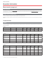 14
14
-
 15
15
-
 16
16
-
 17
17
-
 18
18
-
 19
19
-
 20
20
-
 21
21
-
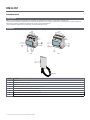 22
22
-
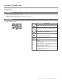 23
23
-
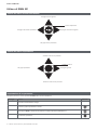 24
24
-
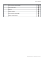 25
25
-
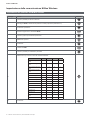 26
26
-
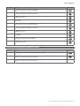 27
27
-
 28
28
-
 29
29
-
 30
30
-
 31
31
-
 32
32
-
 33
33
-
 34
34
-
 35
35
-
 36
36
-
 37
37
-
 38
38
-
 39
39
-
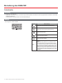 40
40
-
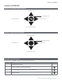 41
41
-
 42
42
-
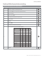 43
43
-
 44
44
-
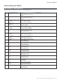 45
45
-
 46
46
-
 47
47
-
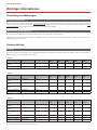 48
48
-
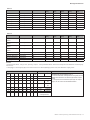 49
49
-
 50
50
-
 51
51
-
 52
52
-
 53
53
-
 54
54
-
 55
55
-
 56
56
-
 57
57
-
 58
58
-
 59
59
-
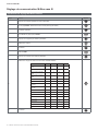 60
60
-
 61
61
-
 62
62
-
 63
63
-
 64
64
-
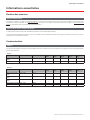 65
65
-
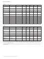 66
66
-
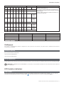 67
67
-
 68
68
-
 69
69
-
 70
70
-
 71
71
-
 72
72
-
 73
73
-
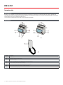 74
74
-
 75
75
-
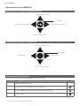 76
76
-
 77
77
-
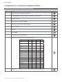 78
78
-
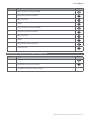 79
79
-
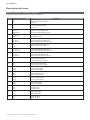 80
80
-
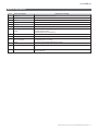 81
81
-
 82
82
-
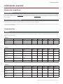 83
83
-
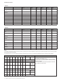 84
84
-
 85
85
-
 86
86
-
 87
87
-
 88
88
-
 89
89
-
 90
90
-
 91
91
-
 92
92
-
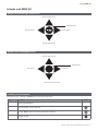 93
93
-
 94
94
-
 95
95
-
 96
96
-
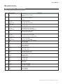 97
97
-
 98
98
-
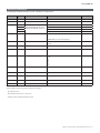 99
99
-
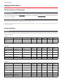 100
100
-
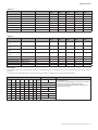 101
101
-
 102
102
-
 103
103
-
 104
104


CARLO GAVAZZI EM24DINAV21XW1EPFB Manual de usuario
- Tipo
- Manual de usuario
en otros idiomas
Artículos relacionados
-
CARLO GAVAZZI EM24DINAV23XE1PFB Manual de usuario
-
CARLO GAVAZZI EM24DINAV23XM1SFA El manual del propietario
-
-
-
-
-
-
-
-
CARLO GAVAZZI EM2696AV63HR2S1XX Guía de instalación
