
THANK YOU
We appreciate the trust and condence you have placed in Deant through the purchase of this motion security light.
We strive to continually create quality products designed to enhance your home. Visit us online to see our full line of
products available for your home improvement needs. Thank you for choosing Deant!
USE AND CARE GUIDE
MOTION SECURITY LIGHT
Questions, problems, missing parts?
Before returning to the store, call Deant Customer Service
8 a.m.-7 p.m., EST, Monday-Friday, 9 a.m. - 6 p.m., EST, Saturday
1-866-308-3976
HOMEDEPOT.COM
Item #1004365415
Model #DF-5909-WH

2
Table of Contents
Table of Contents ......................................2
Safety Information ....................................2
Warranty ...................................................2
5-Year Limited Warranty ........................2
Pre-Installation .........................................3
Planning Installation ..............................3
Specications ........................................3
Tools Required .......................................3
Hardware Included .................................4
Package Contents ..................................4
Installation ................................................5
Operation...................................................8
Care and Cleaning ..................................11
Troubleshooting ......................................11
Safety Information
PRECAUTIONS
□ Please read and understand this entire manual
before attempting to assemble, install, or operate
this light xture.
□ This light xture requires a 120-Volt AC power
source.
□ Some codes require installation by a qualied
electrician.
□ This light xture must be properly grounded.
□ This light xture should be installed outdoors to a
wall or eave.
□ The light xture should be mounted approximately
8 ft. (2.4 m) above the ground. If the light xture
is mounted higher than recommended, aiming the
sensor down will reduce the coverage area.
WARNING: Turn the power off at the circuit breaker or
fuse. Place tape over the circuit breaker switch and verify
power is off at the light xture.
CAUTION: To avoid water damage and the risk of
electrical shock, the motion sensor controls must be facing
the ground when the installation is complete.
CAUTION: Burn hazard. Allow the light xture to cool
before touching.
NOTICE: Do not connect this light xture to a dimmer switch or
timer.
Warranty
5-YEAR LIMITED WARRANTY
WHAT IS COVERED
This product is guaranteed to be free of factory defective parts and workmanship for a period of 5 years from date
of purchase. Purchase receipt is required for all warranty claims.
WHAT IS NOT COVERED
This guarantee does not include repair service, adjustment and calibration due to misuse, abuse or negligence, or
LEDs. Any damage to the light xture resulting from the use of chemicals or a pressure washer machine are not
covered by this warranty. Unauthorized service or modication of the product or of any furnished component will
void this warranty in its entirety. This warranty does not include reimbursement for inconvenience, installation,
setup time, loss of use, unauthorized service, or return shipping charges. This warranty is not extended to other
equipment and components that a customer uses in conjunction with this product.
No service parts available for this product.
Contact the Customer Service Team at 1-866-308-3976 or visit www.homedepot.com.

3 HOMEDEPOT.COM
Please contact 1-866-308-3976 for further assistance.
Pre-Installation
PLANNING INSTALLATION
Before installing the light xture, ensure that all parts are present. Compare parts with the Hardware Included and
Package Contents sections. If any part is missing or damaged, do not attempt to assemble, install, or operate this
light xture.
Estimated installation time: 30 minutes
SPECIFICATIONS
Range
Up to 50 ft. (15.2 m) (Varies with surrounding temperature)
Sensing angle
Up to 270°
Electrical load - LED
33 Watts
LED lumens
2000
LED color temperature
3000K (warm white)
Power requirements
120 VAC, 60 Hz
Operating modes
Test (day and night), Motion activated (night only), Manual (night only)
Time delay (motion)
5 or 20 minutes (night only)
DualBrite timer (night only)
Off, 5 hours, dusk-to-dawn
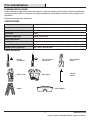
TOOLS REQUIRED
Phillips
screwdriver
1/8 in. Flathead
screwdriver
Wire strippers/
cutters
Circuit tester Work gloves
Silicone
sealant
Ladder Safety goggles

4
Pre-Installation (continued)
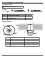
HARDWARE INCLUDED
NOTE: Hardware shown to actual size.
AA BB CC
Part Description Quantity
AA Clear rubber gasket (pre-installed) 2
BB #8 Mounting plate screw (pre-installed) 2
CC #10 Mounting plate screw 2
PACKAGE CONTENTS
Part Description Quantity
A Light panel 2
B Canopy 1
C Motion sensor 1
D Mounting plate 1
E Heat sink 2
C
A
E
D
BB
AA
B

5 HOMEDEPOT.COM
Please contact 1-866-308-3976 for further assistance.
Installation
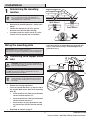
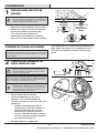
1
Determining the mounting
location
NOTE: The light xture should be mounted approximately
8 ft. (2.4 m) above the ground. If the light xture is
mounted higher than recommended, aiming the sensor
down will reduce the coverage area.
□ Determine the mounting location – wall or eave
mount.
□ Position the light panels (A) in the general
direction of the desired light coverage.
□ If needed, rotate the motion sensor (C) so the
controls face the ground after installation.
Wall Mount
Eave Mount
Wiring the mounting plate
IMPORTANT: Push-in terminals not for reuse.
To remove the wires from the mounting plate connector, twist the wires
back and forth as the wires are being pulled from the mounting plate.
If the house wiring is solid copper wire, proceed with
step 2. If the house wiring is stranded copper wire,
proceed to step 3.
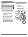
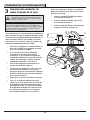
2
Connecting solid copper house
wire
WARNING: Turn the power off at the circuit breaker or
fuse. Place tape over the circuit breaker switch and verify
power is off at the light xture.
IMPORTANT: This mounting plate is designed for solid-core 14
or 12 AWG wire. If the house wiring is stranded wire, see step 3,
Connecting stranded house wire below.
NOTE: If necessary, strip 5/8 in. of insulation from
junction box wires. Use the wire length measuring guide
on the back of the mounting plate to ensure the correct
wire length.
□ Remove the existing light xture.
□ Insert the junction box wires (1) into the side of
the terminal block on the back of the mounting
plate (D).
□ Insert the white wire from the junction box
into the terminal marked “N”.
□ Insert the black wire from the junction box
into the terminal marked “L”.
□ Insert the bare or green ground wire from
the junction box into the terminal marked
“G”.
□ Proceed to step 4, page 7.
5/8"
A
C
D
D
1
1

6
Installation (continued)
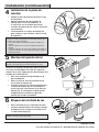
3
Connecting stranded copper
house wire
WARNING: Turn the power off at the circuit breaker or
fuse. Place tape over the circuit breaker switch and verify
power is off at the light xture.
IMPORTANT: Use only NM-B 14/2 or 12/2 wire for the pigtail. The
pigtail wire size must match the existing house wiring (14 AWG or
12 AWG). Color match the solid-core wire and the house wire when
connecting together.
If the house wiring is stranded wire instead of solid-
core copper wire, a pigtail using solid-core wire (2) will
be required (not included). Follow these instructions
to connect the mounting plate (D) using the pigtail
method.
□ Cut 4 to 6 inches of NM-B wire (2) to match the
existing house wire (14 AWG or 12 AWG).
□ If necessary, strip 5/8 in. of insulation from
junction box wires (1).
□ Strip 5/8 in. of insulation from one end of the
solid-core wire (2).
□ Attach the two wires together using a wire
nut(3 - not included). Ensure the solid-core
wire insulation matches the junction box wire.
□ Repeat for the remaining two wires.
□ To attach the solid-core pigtail to the mounting
plate (D), strip 5/8 in. of insulation from the
other end of the solid-core wire. Use the wire
length measuring guide on the back of the
mounting plate (D) to ensure the correct wire
length.
□ Insert the pigtail wires into the side of the
terminal block on the back of the mounting
plate (D).
□ Insert the white pigtail wire into the
terminal marked “N”.
□ Insert the black pigtail wire into the
terminal marked “L”.
□ Insert the bare or green ground pigtail
wire into the terminal marked “G”.
5/8"
D
3
2
D
1
1

7 HOMEDEPOT.COM
Please contact 1-866-308-3976 for further assistance.
Installation (continued)
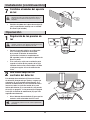
4
Installing the mounting plate
□ Place the mounting plate (D) against the
junction box.
□ Tighten the two mounting screws (BB) securely
to the junction box. If necessary, use the
screws that were removed from the existing
light xture. Do not overtighten.
□ Firmly pull on the mounting plate(D) to ensure
it is securely attached to the junction box.
IMPORTANT: Use the larger mounting plate screws if the pre-
installed screws are too small for the junction box holes.
• Unscrew the mounting plate screws from the mounting plate
using a screwdriver.
• Remove the rubber gaskets from the mounting plate screws.
• Place the rubber gaskets on the larger mounting plate screws and
screw the screws into the mounting plate using a screwdriver.
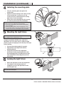
5
Mounting the light fixture
NOTICE: The light xture must securely snap onto the mounting
plate completely for the locking handle to close.
During the installation, DO NOT press against the
light panels (A) or the heat sinks (E). Move the light
panels(A) apart and apply pressure directly to the light
xture housing.
□ Pull up on the locking handle (4) to unlock.
□ Align the back of the light xture with the
mounting plate (D).
□ Firmly press the center of the light xture
housing to securely snap the light xture onto
the mounting plate (D). The light xture must be
fully seated onto the mounting plate (D) all the
way around.
6
Locking the light fixture
□ Rotate the light xture to the desired position.
□ Press down on the locking handle (4)
completely to secure the light xture to the
mounting plate (D).
NOTICE: Gently pull on the light xture to ensure it is securely
connected to the mounting plate.
D
D
E
A
4
4
D
BB

8
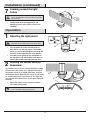
Installation (continued)
7
Caulking around the light
fixture
CAUTION: Failure to completely caulk around the light
xture’s mounting plate could result in water seepage into
the junction box.
□ Caulk around the mounting plate (D) and
mounting surface with silicone sealant (not
included).
Operation
1
Adjusting the light panels
CAUTION: Heat sinks can be warm to the touch. Turn
light xture off for 5 minutes before touching heat sinks.
□ Turn the power on at the circuit breaker or
fuse and turn on the wall switch. The motion
sensor (C) will need to completely warm up (60
seconds) before beginning the setup process.
□ If needed, gently grasp the top and bottom of
the light panels (A) and tilt them up or down or
side to side to adjust the light coverage area.
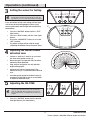
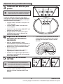
2
Rotating the sensor controls
downward
This motion sensor (C) has a built-in detection system
to help ensure the sensor (C) is adjusted correctly. If
the motion sensor (C) is angled incorrectly, all of the
control lights on the bottom of the sensor (C) will come
on and the light panels (A) will turn off. The light will
stay off until the motion sensor (C) has been adjusted
correctly.
□ Rotate the motion sensor (C) so the controls
face toward the ground.
NOTE: If the motion sensor is NOT positioned correctly, all
of the control lights will be glowing (shown).
DUALBRITE
D2D
5H
OFF
HIGH
MED
LOW
20 MIN
5 MIN
TEST
SENS ON TIME
DUALBRITE
D2D
5H
OFF
HIGH
MED
LOW
20 MIN
5 MIN
TEST
SENS ON TIME
A
A
C
D
C

9 HOMEDEPOT.COM
Please contact 1-866-308-3976 for further assistance.
Operation (continued)
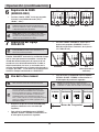
3
Setting the sensor for testing
NOTE: When the “ON-TIME” is set to the “TEST” position,
the light xture will operate during the day or night. The
light will stay on for 5 seconds after all motion is stopped.
Press the button next to each setting until the light
next to the desired setting begins to ash. Stop
pressing the button and the light will stop ashing
momentarily.
□ Press the “ON-TIME” button until the “TEST”
light ashes.
□ Press the “SENS” button until the “Low” light
ashes.
□ Ensure the “DUALBRITE” feature is set to the
“OFF” position.
□ The above settings will be used for step 4
(Adjusting the Motion Sensor Detection Zone).
DUALBRITE
D2D
5H
OFF
HIGH
MED
LOW
20 MIN
5 MIN
TEST
SENS ON TIME
DUALBRITE
D2D
5H
OFF
HIGH
MED
LOW
20 MIN
5 MIN
TEST
SENS ON TIME
4
Adjusting the motion sensor
detection zone
□ Perform a “walk test”: walk in an arc across
the front of the motion sensor (C).
□ Watch the light. The light will come on when
motion has been detected.
□ Stop, wait for the light to turn off, and then
begin walking again.
□ Continue this process to determine if the
motion sensor (C) is aimed toward the desired
area.
□ If needed, gently grasp the motion sensor (C)
and move it from side to side or up and down
to adjust the detection zone.
5
Adjusting the ON-TIME
NOTE: When the “ON-TIME” button is set to the 5 or 20
minute position, the light will only come on during the
night. The “ON-TIME” button determines the amount of
time the light will stay on full bright after all motion has
stopped.
□ Press the “ON-TIME” button until the desired
time light ashes (5 or 20 minutes).
DUALBRITE
D2D
5H
OFF
HIGH
MED
LOW
20 MIN
5 MIN
TEST
SENS
ON TIME
DUALBRITE
D2D
5H
OFF
HIGH
MED
LOW
20 MIN
5 MIN
TEST
SENS
ON TIME
DUALBRITE
D2D
5H
OFF
HIGH
MED
LOW
20 MIN
5 MIN
TEST
SENS
ON TIME
TEST 5 Minutes 20 Minutes
C
C

10
Operation (continued)
6
Adjusting the SENS
□ Press the “SENS” button until the desired
sensitivity light ashes (“Low”, “Med”, “High”).
NOTE: The motion sensor is more sensitive to motion
moving across the front of the sensor. The motion sensor is
less sensitive to motion moving directly toward the sensor.
NOTE: The higher the “SENS” setting (sensitivity), the
greater the possibility of false triggering. To reduce false
triggering, press the “SENS” button until the “Low” light
ashes.
DUALBRITE
D2D
5H
OFF
HIGH
MED
LOW
20 MIN
5 MIN
TEST
SENS
ON TIME
DUALBRITE
D2D
5H
OFF
HIGH
MED
LOW
20 MIN
5 MIN
TEST
SENS
ON TIME
DUALBRITE
D2D
5H
OFF
HIGH
MED
LOW
20 MIN
5 MIN
TEST
SENS
ON TIME
LOW MEDIUM HIGH
7
Adjusting the DUALBRITE
setting
NOTE: Switching this setting to “OFF” will not affect the
motion detection (ON-TIME) setting or the daylight sensor
(photocell).
The “DUALBRITE” button determines the amount
of time the lights stay on at an accent level after
sundown when no motion has been detected. When
motion is detected, the lights will turn on full bright
for the duration of the selected “ON-TIME” setting. The
light will return to the accent level for the duration of
the selected “DUALBRITE” time.
□ Press the “DUALBRITE” button until the desired
light ashes (OFF, 5 hours, or D2D (dusk-to-
dawn; sunset to sunrise).
DUALBRITE
D2D
5H
OFF
HIGH
MED
LOW
20 MIN
5 MIN
TEST
SENS ON TIME
DUALBRITE
D2D
5H
OFF
HIGH
MED
LOW
20 MIN
5 MIN
TEST
SENS ON TIME
DUALBRITE
D2D
5H
OFF
HIGH
MED
LOW
20 MIN
5 MIN
TEST
SENS ON TIME
OFF 5 HOURS D2D
(Dusk-to-Dawn)
8
Using manual mode
NOTE: In order to use manual mode, the light xture must
be wired through a wall switch.
NOTE: Manual mode overrides the motion sensor so the
light will shine full bright without motion being detected.
This feature only works at night and only for one night at a
time. The motion sensorwill reset to motion sensing mode
after 6 hours or sunrise, whichever comes rst. Manual
mode is toggled on and off using a wall switch.
□ Ensure the power to the light is ON and the
sensor has warmed up (60 seconds).
□ To turn manual mode on, switch the power
OFF–ON–OFF–ON at the wall switch within 3
seconds.
□ To turn manual mode off, switch the power
OFF–ON–OFF–ON at the wall switch within 3
seconds.
NOTE: If the power to the light xture is off for more than
5 seconds, allow the motion sensor to warm up prior to
switching to manual mode.
OFF OFFON ON
Less than 3 seconds

11 HOMEDEPOT.COM
Please contact 1-866-308-3976 for further assistance.
Care and Cleaning
□ To prolong the original appearance, clean the light xture with clear water and a soft, damp cloth only.
□ Do not use paints, solvents, or other chemicals on this light xture. They could cause a premature
deterioration of the nish. This is not a defect in the nish and will not be covered by the warranty.
□ Do not spray the light xture with a hose or power washer.
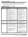
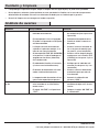
Troubleshooting
Problem Possible Cause Solution
The light will not come
on.
□ The motion sensor is not angled
correctly.
□ Rotate the motion sensor correctly
(see step 2 under Operation).
□ The light switch is turned off. □ Turn the light switch on.
□ The fuse is blown or the circuit breaker
is turned off.
□ Replace the fuse or turn the circuit
breaker on.
□ The light xture is not properly
attached to the mounting plate, if this is
a new installation.
□ Re-install the light xture to the
mounting plate (see steps 5 and 6
under Installation).
□ The ON-TIME switch is set to 5 or 20
so the daylight turn-off (photocell) is
in effect.
□ Recheck after dark or use the TEST
feature (see steps 3 and 4 under
Operation).
□ The circuit wiring is incorrect (if this is
a new installation).
□ Verify the wiring is correct (see steps
2 and 3 under Installation).
□ The motion sensor is aimed in the
wrong direction.
□ Re-aim the motion sensor to cover
the desired area.
□ The outside air temperature is close to
the same as a person’s body heat.
□ Increase the “SENS” setting.
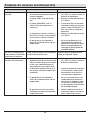
The light comes on
during the day.
□ The motion sensor may be installed in a
relatively dark location.
□ The light xture is operating normally
under these circumstances.
□ The “ON-TIME” setting is set to “TEST”. □ Set the “ON-TIME” setting to the 5 or
20 minute setting.
The light comes on for
no apparent reason.
□ The motion sensor may be sensing
small animals or automobile trafc.
□ Decrease the “SENS” setting or
reposition the motion sensor.
□ The “SENS” setting is set too high. □ Decrease the “SENS” setting.
□ The “DUALBRITE” setting is in the 5
hour or D2D (dusk-to-dawn) setting.
□ The light xture is operating normally
under these circumstances. Set
“DUALBRITE” to OFF if no accent
lighting is desired.
□ The outside temperature is much
warmer or cooler than a person’s body
heat (summer or winter).
□ Decrease the “SENS” setting.
□ The light xture is wired through a
dimmer or timer.
□ Do not use a dimmer or timer to
control the light xture. Replace the
dimmer or timer with a standard on/
off wall switch.

12
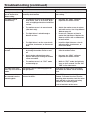
Troubleshooting (continued)
Problem Possible Cause Solution
The lights turn off too
late in the Dusk-to-
Dawn setting.
The light xture may be installed in a
relatively dark location.
Relocate the light xture or use the 5
hour setting.
The lights stay on
continuously.
□ The motion sensor may be picking up a
heat source, such as an air vent, dryer
vent, or brightly painted, heat-reective
surface.
□ Decrease the “SENS” setting or
reposition the motion sensor.
□ The motion sensor is in manual mode
(after dark only).
□ Switch the motion sensor to auto or
wait until sunrise. See Using Manual
Mode on page 10.
□ The light xture is wired through a
dimmer or timer.
□ Do not use a dimmer or timer to
control the light xture. Replace the
dimmer or timer with a standard on/
off wall switch.
□ The light xture is on the same circuit
as a motor, transformer, or uorescent
bulb.
□ Install the light xture on a circuit
without motors, transformers, or
uorescent bulbs.
The lights ash on
and off.
□ Heat or light from the light panels may
be turning the motion sensor on and
off.
□ Reposition the light panels away
from the motion sensor.
□ Heat is being reected from other
objects and may be turning the motion
sensor on and off.
□ Decrease the “SENS” setting or
reposition the motion sensor.
□ The motion sensor is in “TEST” mode
and warming up.
□ While in “TEST” mode, the light only
stays on for 5 seconds. Set the “ON-
TIME” to 5 or 20 minutes.
The lights ash once
then stay off in manual
mode.
The motion sensor is detecting light from
the light panels.
Reposition the light panels to keep the
area below the motion sensor relatively
dark.
The wires need to
be removed from the
mounting plate.
The mounting plate connectors will not
release the wires.
Turn OFF power to the light
xture. To remove the wires from the
mounting plate connector, twist the wires
back and forth as the wires are being
pulled from the mounting plate.
Push-in terminals not for reuse.

13 HOMEDEPOT.COM
Please contact 1-866-308-3976 for further assistance.
This device complies with Part 15 of the FCC Rules. Operation is subject to the following two conditions: (1) this
device may not cause harmful interference, and (2) this device must accept any interference received, including
interference that may cause undesired operation.
Warning: Changes or modications to this unit not expressly approved by the party responsible for compliance could
void the user’s authority to operate the equipment.
Note: This equipment has been tested and found to comply with the limits for aClass B digital device, pursuant to
part 15 of the FCC Rules. These limits are designed to provide reasonable protection againstharmful interferencein
a residential installation. This equipment generates, uses and can radiateradio frequency energyand, if not
installed and used in accordance with the instructions, may causeharmful interferenceto radio communications.
However, there is no guarantee that interference will not occur in a particular installation. If this equipment does
causeharmful interferenceto radio or television reception, which can be determined by turning the equipment off
and on, the user is encouraged to try to correct the interference by one or more of the following measures:
- Reorient or relocate the receiving antenna.
- Increase the separation between the equipment and receiver.
- Connect the equipment into an outlet on a circuit different from that to which the receiver is connected.
- Consult the dealer or an experienced radio/TV technician for help.
CAN ICES-005 (B)/NMB-005 (B)

Questions, problems, missing parts?
Before returning to the store, call Deant Customer Service
8 a.m.-7 p.m., EST, Monday-Friday, 9 a.m. - 6 p.m., EST, Saturday
1-866-308-3976
HOMEDEPOT.COM
Retain this manual for future use.
209780-01A

GRACIAS
Agradecemos la fe y la conanza que usted ha depositado en Deant al comprar esta luz de seguridad por
movimiento. Procuramos crear continuamente productos de calidad diseñados para mejorar su hogar. Visítenos en
internet para ver nuestra línea completa de productos disponibles que necesita para el mejoramiento de su hogar.
¡Gracias por escoger Deant!
GUÍA PARA EL USO Y CUIDADO
LUZ DE SEGURIDAD POR MOVIMIENTO
¿Tiene preguntas, problemas o piezas faltantes?
Antes de devolverlo a la tienda, llame a Servicio al Cliente de Deant
de 08 a.m.-7 p.m., EST, Lunes - Viernes, 09 a.m.-6 p.m., EST, sábado.
1-866-308-3976
HOMEDEPOT.COM
Articulo #1004365415
Modelo #DF-5909-WH

16
Contenido
Contenido ................................................16
Información de seguridad ......................16
Garantía...................................................16
5 años de garantía limitada .................16
Antes de la instalación ...........................17
Planicación de la Instalación .............17
Especicaciones ..................................17
Herramientas Requeridas ....................17
Ferretería Incluida ................................18
Contenido del Paquete .........................18
Instalación ..............................................19
Operación ................................................22
Cuidado y limpieza .................................25
Análisis de averías .................................25
Información de seguridad
PRECAUCIONES
□ Por favor lea y entienda todo este manual antes de
tratar de ensamblar, instalar u operar este aparato
de luz.
□ Esta lámpara requiere una fuente de alimentación
de 120 voltios de CA.
□ Algunos códigos exigen que la instalación la realice
un electricista calicado.
□ Este aparato de luz debe estar correctamente
conectado a tierra.
□ Esta lámpara debe ser instalada fuera de casa
sobre una pared o aleros.
□ Esta lámpara debe ser instalada aproximadamente
a 8 pies (2,4 m) por encima del suelo. Si se la
instala a una altura más alta de la recomendada, se
reducirá la zona de cobertura si apunta el detector
hacia abajo.
ADVERTENCIA: Desconecte la energía eléctrica en el
disyuntor o en el fusible. Coloque cinta aislante sobre el
interruptor disyuntor y compruebe que no haya energía
eléctrica en el aparato de luz.
PRECAUCIÓN: Para evitar daños por el agua y el
riesgo de una descarga eléctrica, los controles del detector
de movimiento deben estar de cara al suelo cuando la
instalación esté terminada.
PRECAUCIÓN: Peligro de quemaduras. Deje que el
aparato de luz se enfríe antes de tocarlo.
AVISO: No conecte este aparato de luz a un interruptor reductor de
luz ni a un temporizador.
Garantía
5 AÑOS DE GARANTÍA LIMITADA
LO QUE SE CUBRE
Se garantiza que este producto no tiene partes defectuosas de fábrica o de mano de obra por un período de 5 años
desde la fecha de compra. Se necesita el recibo de compra para todos los reclamos de garantía.
LO QUE NO SE CUBRE
Esta garantía no incluye el servicio de reparación, ajuste y calibración debido al mal uso, abuso o negligencia, o
LEDs. Cualquier daño en el aparato de luz como resultado de usar productos químicos o lavadora a presión no están
cubiertos por esta garantía. Los servicios no autorizados o las modicaciones hechas al producto o a cualquier
componente invalidarán esta garantía en su totalidad. Esta garantía no incluye reembolso por inconveniencia,
instalación, tiempo de instalación, perdida de uso, servicio no autorizado, o gastos de envío. Esta garantía no se
extiende a otros equipos o componentes que el consumidor usa junto con este producto.
No hay piezas de servicio disponibles para este producto.
Póngase en contacto con el personal de servicio al cliente al 1-866-308-3976 o visite el sitio www.homedepot.com.

17 HOMEDEPOT.COM
Por favor, póngase en contacto al 1-866-308-3976 para obtener más ayuda.
Antes de la instalación
PLANIFICACIÓN DE LA INSTALACIÓN
Antes de instalar el aparato de luz, esté seguro que estén todas las piezas. Compare las piezas con la Ferretería
incluida y las secciones de Contenidos del paquete. Si cualquier pieza falta o está dañada, no intente ensamblar,
instalar ni operar este aparato de luz.
Tiempo estimado para la instalación: 30 minutos
ESPECIFICACIONES
Alcance
Hasta 50 pies (15,2 m) (Varía con la temperatura circundante)
Ángulo de detección
Hasta 270°
Carga eléctrica - DEL
33 Vatios
Lúmenes LED
2000
LED de temperatura de color
3000K (blanco cálido)
Requisitos de la energía eléctrica
120 VCA, 60 Hz
Fases de operación
Prueba (día y noche), activado por movimiento (solamente la
noche), manual (solamente la noche)
Retardo de tiempo (movimiento)
5 o 20 minutos (solamente la noche)
Temporizador DualBrite (solamente la noche)
Apagado, 5 horas, del crepúsculo al amanecer
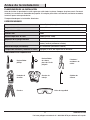
HERRAMIENTAS REQUERIDAS
Destornillador
phillips
Destornillador
de cabeza
plana de 1/8 de
pulgada
Peladores/
cortadores de
cables
Probador de
circuitos
Guantes de
trabajo
Sellador de
silicona
Escalera Gafas de seguridad

18
Antes de la instalación (continuación)
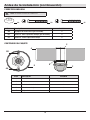
FERRETERÍA INCLUIDA
NOTA: La ferretería se muestra en su tamaño real
AA BB CC
Pieza Descripción Cantidad
AA Empaque de caucho claro (pre-instalado) 2
BB Tornillo n° 8 de la placa de montaje (pre-instalado) 2
CC Tornillo n° 10 de la placa de montaje 2
CONTENIDO DEL PAQUETE
Pieza Descripción Cantidad
A Panel de luz 2
B Cubierta 1
C Detector de movimiento 1
D Placa de montaje 1
E Disipador de calor 2
C
E
D
A
B
BB
AA

19 HOMEDEPOT.COM
Por favor, póngase en contacto al 1-866-308-3976 para obtener más ayuda.
Instalación
1
Determinación del sitio de
montaje
NOTA: Esta lámpara debe ser instalada aproximadamente
a 8 pies (2,4 m) por encima del suelo. Si se la instala a una
altura más alta de la recomendada, se reducirá la zona de
cobertura si apunta el detector hacia abajo.
□ Determine el sitio de montaje – pared o alero.
□ Coloque los paneles de luz (A) en la dirección
general de la cobertura de luz deseada.
□ Si es necesario, gire el detector de
movimiento(C) de modo que los controles
miren hacia el suelo después de la instalación.
Montaje
en pared
Montaje en
alero
Cableado de la placa de montaje
IMPORTANTE: Los terminales insertables no son reutilizables.
Para retirar los conductores del conector de la placa de montaje, gire
los conductores hacia atrás y hacia delante mientras se los jala de la
placa de montaje.
Si el cableado de la casa está hecho con conductor de
cobre sólido, siga al paso 2. Si el cableado de la casa
está hecho con conductor de cobre trenzado, siga al
paso 3.
2
Conexión del conductor de
cobre sólido de casa
ADVERTENCIA: Desconecte la energía eléctrica en el
disyuntor o en el fusible. Coloque cinta aislante sobre el
interruptor disyuntor y compruebe que no haya energía
eléctrica en el aparato de luz.
IMPORTANTE: Esta placa de montaje está diseñada para
conductores de núcleo sólido del calibre 14 o 12 AWG. Si el cableado
de la casa está hecho con conductor trenzado, vea a continuación el
paso 3, Conexión del conductor trenzado de la casa.
NOTA: Si es necesario, pele 5/8 de pulgada de
aislamiento de los cables de la caja de conexiones. Use
la guía de medición de longitud del conductor en la parte
de atrás de la placa de montaje para asegurarse que la
longitud del conductor sea la correcta.
□ Retire el aparato de luz existente.
□ Inserte los conductores de la caja de
empalmes (1) en el lado del bloque de
terminales en la parte de atrás de la placa de
montaje (D).
□ Inserte el cable blanco de la caja de
conexiones en el terminal marcado “N”.
□ Inserte el cable negro de la caja de
conexiones en el terminal marcado “L”.
□ Inserte el conductor desnudo o verde de
conexión a tierra de la caja de empalmes
en el terminal marcado “G”.
□ Prosiga al paso 4, página 21.
5/8"
A
C
D
D
1
1

20
Instalación (continuación)
3
Conexión del conductor de
cobre trenzado de la casa
ADVERTENCIA: Desconecte la energía eléctrica en el
disyuntor o en el fusible. Coloque cinta aislante sobre el
interruptor disyuntor y compruebe que no haya energía
eléctrica en el aparato de luz.
IMPORTANTE: Utilice únicamente conductor NM-B 14/2 o 12/2
para el conductor exible. El tamaño del conductor exible debe
coincidir con el del cableado existente de la casa (14 AWG o 12 AWG).
El color del conductor de núcleo sólido y del conductor de la casa
coinciden cuando se conectan entre sí.
Si el cableado de la casa está hecho con conductor de
cobre trenzado en lugar de conductor de cobre sólido,
se necesitará un conductor exible con conductor de
cobre de núcleo sólido (2) (no incluido). Siga estas
instrucciones para conectar la placa de montaje (D)
utilizando el método de conductor exible.
□ Corte de 4 a 6 pulgadas el conductor NM-B (2)
para que coincida con el conductor existente
de la casa (14 AWG o 12 AWG).
□ Si es necesario, pele 5/8 de pulgada de
aislamiento de los cables de la caja de
conexiones (1). Use la guía de medición de
longitud del conductor en la parte de atrás de
la placa de montaje para asegurarse que la
longitud del conductor sea la correcta.
□ Pele 5/8 de pulgada del aislamiento de un
extremo del conductor sólido (2).
□ Conecte los dos conductores entre sí usando
una conector de alambre (3, no incluida).
Asegúrese de que el aislamiento del conductor
de núcleo sólido coincida con el del conductor
de la caja de empalmes.
□ Repita igual en los dos conductores restantes.
□ Para unir el conductor exible con núcleo
sólido a la placa de montaje (D), pele unos 5/8
de pulgada del aislamiento del otro extremo
del conductor sólido. Use la guía de medición
de longitud del conductor de la parte de atrás
de la placa de montaje (D) para asegurarse
que la longitud conductor sea la correcta.
□ Inserte los conductores exibles en el lado del
bloque de terminales de la parte de atrás de la
placa de montaje (D).
□ Inserte el conductor exible color blanco
en el terminal marcado “N”.
□ Inserte el conductor exible color negro
en el terminal marcado “L”.
□ Inserte el conductor exible a tierra desnudo
o verde en el terminal marcado “G”.
5/8"
D
3
2
D
1
1

21 HOMEDEPOT.COM
Por favor, póngase en contacto al 1-866-308-3976 para obtener más ayuda.
Instalación (continuación)
4
Instalación de la placa de
montaje
□ Coloque la placa de montaje (D) contra la caja
de conexiones.
□ Apriete rmemente los dos tornillos de
montaje (BB) a la caja de empalmes. Si
es necesario, use los tornillos que fueron
retirados del aparato de luz anterior. No apriete
excesivamente.
□ Jale rmemente en la placa de montaje (D)
para asegurarse que esté bien sujeta a la caja
de empalmes.
IMPORTANTE: Use los tornillos más grandes de la placa de
montaje si los tornillos preinstalados son demasiado pequeños para
los oricios de la caja de empalmes.
• Con un destornillador, desatornille los tornillos de la placa de
montaje.
• Retire los empaques de caucho de los tornillos de la placa de
montaje.
• Coloque los empaques de caucho en los tornillos más grandes de
la placa de montaje y con un destornillador atornille los tornillos a
la placa de montaje.
5
Montaje del aparato de luz
AVISO: El artefacto de luz debe encajar completamente y a presión
en la placa de montaje para que el mango de bloqueo se cierre.
Durante la instalación, NO presione sobre los paneles
de luz (A) o los disipadores de calor (E). Separe los
paneles de luz (A) y aplique presión directamente en el
bastidor del artefacto de luz.
□ Hale hacia arriba del mango de bloqueo (4)
para desbloquear.
□ Alinee la parte de atrás del artefacto de luz
con la placa de montaje (D).
□ Presione rmemente el centro del bastidor del
artefacto de luz para que el artefacto de luz
encaje a presión y con rmeza en la placa de
montaje (D). El artefacto de luz debe quedar
completamente asentado en la placa de
montaje (D) en todo su alrededor.
6
Bloqueo del artefacto de luz
□ Gire el artefacto de luz a la posición deseada.
□ Presione completamente hacia abajo el mango
de bloqueo (4) para sujetar el artefacto de luz
a la placa de montaje (D).
AVISO: Hale con cuidado el artefacto de luz para asegurarse que
esté bien conectado a la placa de montaje.
D
E
A
4
D
4
D
BB

22
Instalación (continuación)
7
Calafatee alrededor del aparato
de luz
PRECAUCIÓN: Si no se calafatea completamente
alrededor de la placa de montaje del artefacto de luz se
podría producir una ltración de agua hacia la caja de
empalmes.
□ Calafatee alrededor de la placa de montaje (D)
y de la supercie de montaje con un sellador
de silicona (no incluido).
Operación
1
Regulación de los paneles de
luz
PRECAUCIÓN: Los disipadores de calor pueden estar
calientes cuando los toque. Apague el aparato de luz por 5
minutos antes de tocar los disipadores de calor.
□ Conecte la energía eléctrica en el disyuntor
o en el fusible y encienda el interruptor
de la pared. El detector de movimiento
(C) necesitará calentarse completamente
(60segundos) antes de empezar el proceso de
puesta a punto.
□ Si es necesario, sujete con suavidad la parte
superior e inferior de los paneles de luz (A) e
inclínelos hacia arriba o hacia abajo o de lado
a lado para regular el área de cobertura de
la luz.
2
Giro hacia abajo de los
controles del detector
Este detector de movimiento (C) tiene un sistema
de detección incorporado que ayuda y asegura que
el detector (C) esté regulado correctamente. Si el
detector de movimiento (C) está inclinado de forma
incorrecta, todas las luces de control de la parte
inferior del detector (C) se encenderán y los paneles
de luz (A) se apagarán. La luz permanecerá apagada
hasta que al detector de movimiento (C) haya sido
regulado correctamente.
□ Gire el detector de movimiento (C) para que los
controles estén orientados hacia el suelo.
NOTA: Si al detector de movimiento NO se lo coloca
correctamente, todas las luces de control resplandecerán
(mostrado).
DUALBRITE
D2D
5H
OFF
HIGH
MED
LOW
20 MIN
5 MIN
TEST
SENS ON TIME
DUALBRITE
D2D
5H
OFF
HIGH
MED
LOW
20 MIN
5 MIN
TEST
SENS ON TIME
A
A
C
D
C

23 HOMEDEPOT.COM
Por favor, póngase en contacto al 1-866-308-3976 para obtener más ayuda.
Operación (continuación)
3
Calibración del detector para
prueba
NOTA: Cuando el control “ON-TIME” (“DURACIÓN”) se
coloca en la posición “TEST”, el artefacto de luz funcionará
durante el día o la noche. La luz permanecerá encendida 5
segundos después que todo movimiento se ha detenido.
Presione el botón que está junto a cada reglaje
hasta que la luz junto al reglaje deseado comience a
parpadear. Deje de presionar el botón y la luz dejará
momentáneamente de parpadear.
□ Presione el botón “ON-TIME” hasta que la luz
“TEST” parpadee.
□ Presione el botón “SENS” hasta que la luz
“Low” parpadee.
□ Asegúrese de que la función “DUALBRITE” esté
colocada en la posición “OFF”.
□ El reglaje anterior se utilizará para el paso
4 (Regulación de la zona de detección del
detector de movimiento).
DUALBRITE
D2D
5H
OFF
HIGH
MED
LOW
20 MIN
5 MIN
TEST
SENS ON TIME
DUALBRITE
D2D
5H
OFF
HIGH
MED
LOW
20 MIN
5 MIN
TEST
SENS ON TIME
4
Regulación de la zona de
detección del detector de
movimiento
□ Haga una “prueba caminando”: camine
transversalmente a la parte frontal del detector de
movimiento (C) siguiendo la trayectoria de un arco.
□ Observe la luz. La luz se encenderá cuando
detecte movimiento.
□ Deténgase, espere que la luz se apague, y
luego empiece a caminar de nuevo.
□ Continúe con este proceso para determinar si
el detector de movimiento (C) está apuntando
hacia el área deseada.
□ Si es necesario, sujete suavemente el detector
de movimiento (C) y muévalo de lado a lado o
de arriba hacia abajo para ajustar la zona de
detección.
5
Regulación de la función
ON-TIME
NOTA: Cuando el botón “ON-TIME” está en la posición
de 5 o 20 minutos, la luz solo se encenderá durante la
noche. El botón “ON-TIME” determina la cantidad tiempo
que la luz permanece encendida con la máxima intensidad
después que se ha detenido todo movimiento.
□ Presione el botón “ON-TIME” hasta que
parpadee la luz del tiempo deseado (5 o 20
minutos).
DUALBRITE
D2D
5H
OFF
HIGH
MED
LOW
20 MIN
5 MIN
TEST
SENS
ON TIME
DUALBRITE
D2D
5H
OFF
HIGH
MED
LOW
20 MIN
5 MIN
TEST
SENS
ON TIME
DUALBRITE
D2D
5H
OFF
HIGH
MED
LOW
20 MIN
5 MIN
TEST
SENS
ON TIME
PRUEBA 5 minutos 20 minutos
C
C

24
Operación (continuación)
6
Regulación de SENS
(SENSIBILIDAD)
□ Presione el botón “SENS” hasta que parpadee
la luz de la sensibilidad deseada (“Baja”,
“Media”, “Alta”).
NOTA: El detector de movimiento es más sensible al
movimiento transversal a la parte frontal del detector. El
detector de movimiento es menos sensible al movimiento que
se dirige directamente hacia del detector.
NOTA: Mientras mayor sea la calibración del “SENS”
(sensibilidad), mayor será la posibilidad de falsas alarmas.
Para reducir las activaciones falsas, presione el botón
“SENS” hasta que parpadee la luz “Baja”.
DUALBRITE
D2D
5H
OFF
HIGH
MED
LOW
20 MIN
5 MIN
TEST
SENS
ON TIME
DUALBRITE
D2D
5H
OFF
HIGH
MED
LOW
20 MIN
5 MIN
TEST
SENS
ON TIME
DUALBRITE
D2D
5H
OFF
HIGH
MED
LOW
20 MIN
5 MIN
TEST
SENS
ON TIME
BAJA MEDIA ALTA
7
Regulación del reglaje
DUALBRITE
NOTA: Al cambiar este reglaje a “OFF” no afectará al
reglaje (ON-TIME) de la detección de movimiento ni al
detector de luz diurna (fotocélula).
El botón “DUALBRITE” determina la cantidad de tiempo
que las luces permanecen encendidas a un nivel de
alumbrado decorativo después de la puesta del sol
cuando no se ha detectado movimiento. Cuando se
detecta movimiento, las luces se encienden con la
máxima intensidad durante el tiempo seleccionado en
el reglaje “ON-TIME”. La luz volverá al nivel decorativo
durante el tiempo seleccionado en “DUALBRITE”.
□ Presione el botón “DUALBRITE” hasta que la
luz deseada parpadee (APAGADO, 5 horas, o
D2D (del crepúsculo al amanecer; de la puesta
a la salida del sol).
DUALBRITE
D2D
5H
OFF
HIGH
MED
LOW
20 MIN
5 MIN
TEST
SENS ON TIME
DUALBRITE
D2D
5H
OFF
HIGH
MED
LOW
20 MIN
5 MIN
TEST
SENS ON TIME
DUALBRITE
D2D
5H
OFF
HIGH
MED
LOW
20 MIN
5 MIN
TEST
SENS ON TIME
APAGADO 5 HORAS D2D
(del crepúsculo al
amanecer)
8
Uso del la fase manual
NOTA: Para poder usar el modo manual, el aparato de luz
debe conectarse a través de un interruptor de pared.
NOTA: El modo manual anula al detector de movimiento
para que la luz brille con máxima intensidad sin que
sea necesario detectar movimiento. Esta característica
funciona solamente en la noche y solamente una noche
a la vez. El detector de movimiento se reiniciará en la
modalidad de detección de movimiento después de 6
horas o cuando salga el sol, lo que ocurra primero. El modo
manual se conmuta entre encendido y apagado con el
interruptor de pared.
□ Asegúrese de que la luz está encendida (ON)
y de que el detector se ha calentado (60
segundos).
□ Para activar la modalidad manual, APAGUE-
PRENDA- APAGUE- PRENDA la alimentación en
el interruptor de pared en 3 segundos.
□ Para desactivar la modalidad manual, APAGUE-
PRENDA- APAGUE- PRENDA la alimentación en
el interruptor de pared en 3 segundos.
NOTA: Si la energía eléctrica al aparato de luz es
apagada por más de 5 segundos, deje que el detector de
movimiento se caliente antes del cambio a la fase manual.
APAGADO APAGADOENCENDIDO ENCENDIDO
Menos de 3 segundos

25 HOMEDEPOT.COM
Por favor, póngase en contacto al 1-866-308-3976 para obtener más ayuda.
Cuidado y limpieza
□ Para prolongar la apariencia original, limpie la lámpara solo con agua limpia y un paño suave y húmedo.
□ No use pinturas, solventes ni otros químicos en este aparato de luz. Podrían ser la causa de una prematura
deterioración del acabado. Esto no es un defecto del acabado y no será cubierto por la garantía.
□ No rocíe la lámpara con una manguera o lavadora a presión.
Análisis de averías
Problema Causa Probable Solución
La luz no se enciende. □ El detector de movimiento no está
inclinado correctamente.
□ Gire correctamente el detector
de movimiento (Vea el paso 2 en
Operación).
□ El interruptor de la luz está apagado. □ Encienda el interruptor de la luz.
□ El fusible está quemado o el disyuntor
está desconectado.
□ Cambie el fusible o conecte el
disyuntor.
□ La lámpara no está correctamente
sujetada a la placa de montaje, si se
trata de una nueva instalación.
□ Vuelva a instalar el artefacto de
luz en la placa de montaje (vea
los pasos 5 y 6 en Instalación).
□ Al interruptor ON-TIME (DE DURACIÓN)
se lo pone en 5 o 20, de modo que el
apagado con luz diurna (fotocélula)
está siendo usado.
□ Vuelva a revisar después de que
anochezca o use la función TEST
(PRUEBA) (vea los pasos 3 y 4 en
Operación).
□ El cableado del circuito es incorrecto
(si esta es una instalación nueva).
□ Verique que el cableado esté
correcto (vea los pasos 2 y 3 en
Instalación).
□ El detector de movimiento está enfo-
cando a la dirección incorrecta.
□ Vuelva a enfocar el detector de
movimiento para que cubra el
área deseada.
□ La temperatura del aire exterior está cer-
cana al calor corporal de una persona.
□ Aumente la calibración del
alcance (“SENS”).
La luz se enciende durante
el día.
□ El detector de movimiento puede
estar instalado en un sitio relativa-
mente oscuro.
□ El aparato de luz está operando
normalmente bajo estas circuns-
tancias.
□ El reglaje “ON-TIME” está puesto en
“TEST”.
□ Coloque el reglaje “ON-TIME” en
5 o 20 minutos.

26
Análisis de averías (continuación)
Problema Causa Probable Solución
La luz se enciende sin razón
aparente.
□ El detector de movimiento puede
estar detectando pequeños animales
o tráco automotor.
□ Reduzca la calibración del alcan-
ce (“SENS”) o vuelva a colocar el
detector de movimiento.
□ El reglaje “SENS” está demasiado
alto.
□ Reduzca la calibración del alcan-
ce (“SENS”).
□ El reglaje “DUALBRITE” está en
5 horas o D2D (del crepúsculo al
amanecer).
□ El aparato de luz está operando
normalmente bajo estas circuns-
tancias. Ponga “DUALBRITE” en
OFF si no se desea alumbrado
decorativo.
□ La temperatura exterior está más ca-
liente o más fría que el calor corporal
de una persona (verano o invierno).
□ Reduzca la calibración del alcan-
ce (“SENS”).
□ El aparato de luz está cableado a
través de un reductor de luz o de un
temporizador.
□ No use un reductor de luz o un
temporizador para controlar el
aparato de luz. Cambie el reductor
de luz o el temporizador por un
interruptor de pared estándar de
encendido/apagado.
Las luces se apagan dema-
siado tarde en la calibración
crepúsculo-al-amanecer.
El aparato de luz puede estar instalado en
un sitio relativamente oscuro.
Vuelva a ubicar el aparato de luz o
utilice la calibración 5 horas.
Las luces permanecen en-
cendidas constantemente.
□ El detector de movimiento puede estar
absorbiendo calor de una fuente de calor
como una ventosa de aire, una secadora
de aire, o una supercie pintada con
colores brillantes y que reeja el calor.
□ Reduzca la calibración del alcan-
ce (“SENS”) o vuelva a colocar el
detector de movimiento.
□ El detector de movimiento está en la
fase manual (solamente después que
anochezca).
□ Cambie el detector de movimien-
to a automático o espere hasta
que amanezca. Vea Uso de la
fase manual en la página 24.
□ El aparato de luz está cableado a
través de un reductor de luz o de un
temporizador.
□ No use un reductor de luz o un
temporizador para controlar el
aparato de luz. Cambie el reduc-
tor de luz o el temporizador por
un interruptor de pared estándar
de encendido/apagado.
□ El aparato de luz está en el mismo
circuito que un motor, transformador
o tubo uorescente.
□ Instale el aparato de luz en un
circuito sin motores, transforma-
dores o tubos uorescentes.

27 HOMEDEPOT.COM
Por favor, póngase en contacto al 1-866-308-3976 para obtener más ayuda.
Análisis de averías (continuación)
Este aparato cumple con la Parte 15 de las Reglas de la FCC. La operación está sujeta a las dos siguientes
condiciones: (1) este aparato no puede causar interferencias perjudiciales y (2) este aparato debe aceptar cualquier
interferencia recibida, incluyendo una interferencia que pueda causar un funcionamiento indeseado.
Advertencia: los cambios o modicaciones hechas a esta unidad que no estén expresamente aprobados por la parte
responsable del cumplimiento pueden anular la autoridad del usuario para operar el equipo.
Nota: EstE Equipo ha sido probado y sE lo ENcoNtró quE cumplE coN los límitEs para uN dispositivo digital dE clasE b, dE acuErdo coN la
partE 15 dE las Normas dE la Fcc. Estos límitEs EstáN disEñados para proporcioNar uNa protEccióN razoNablE coNtra iNtErFErENcias
dañiNas EN uNa iNstalacióN rEsidENcial. EstE Equipo gENEra, usa y puEdE irradiar ENErgía dE radioFrEcuENcia y, si No sE lo iNstala y usa dE
acuErdo coN las iNstruccioNEs, puEdE causar iNtErFErENcia dañiNa a las comuNicacioNEs dE radio. siN Embargo, No hay garaNtía dE quE la
iNtErFErENcia No ocurra EN uNa iNstalacióN EN particular. si EstE Equipo causa iNtErFErENcia dañiNa a la rEcEpcióN dE radio o tElEvisióN,
lo quE sE puEdE dEtErmiNar apagaNdo y ENcENdiENdo El Equipo, sE rEcomiENda quE El usuario iNtENtE corrEgir la iNtErFErENcia mEdiaNtE
uNa o más dE las siguiENtEs mEdidas:
- rEoriENtE o rEubiquE la aNtENa rEcEptora.
- aumENtE la sEparacióN ENtrE El Equipo y El rEcEptor.
- coNEctE El Equipo a uN tomacorriENtE EN uN circuito diFErENtE al quE Está coNEctado El rEcEptor.
- para rEcibir ayuda coNsultE coN El distribuidor o coN uN técNico ExpErto EN radio / tv.
CAN ICES-005 (B)/NMB-005 (B)
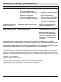
Problema Causa Probable Solución
Las luces se encienden y se
apagan.
□ El calor o la luz de los paneles de luz
pueden estar encendiendo y apagan-
do el detector de movimiento.
□ Reubique los paneles de luz lejos
del detector de movimiento.
□ El calor reejado desde otro objeto
puede estar encendiendo y apagando
al detector de movimiento.
□ Reduzca la calibración del alcan-
ce (“SENS”) o vuelva a colocar el
detector de movimiento.
□ El detector de movimiento está en la
fase “TEST” (PRUEBA) y calentándose.
□ Mientras está en la fase PRUEBA,
la luz sólo queda encendida por
5 segundos. Ponga el control
“ON-TIME” en 5 o 20 minutos.
Las luces destellan una vez
y luego permanecen apaga-
das en la fase manual.
El detector de movimiento está
detectando la luz de los paneles de luz.
Reubique los paneles de luz para
mantener relativamente oscura la
zona por debajo del detector de
movimiento.
Es necesario retirar los
conductores de la placa de
montaje.
Los conectores de la placa de montaje no
liberarán los conductores.
Apague la alimentación del
artefacto de luz. Para retirar los
conductores del conector de la placa
de montaje, gire los conductores
hacia atrás y hacia delante mientras
se los jala de la placa de montaje.
Los terminales insertables no son
reutilizables.

¿Tiene preguntas, problemas o piezas faltantes?
Antes de devolverlo a la tienda, llame a Servicio al Cliente de Deant
de 08 a.m.-7 p.m., EST, Lunes - Viernes, 09 a.m.-6 p.m., EST, sábado.
1-866-308-3976
HOMEDEPOT.COM
Guarde este manual para uso futuro.
209780-01A
-
 1
1
-
 2
2
-
 3
3
-
 4
4
-
 5
5
-
 6
6
-
 7
7
-
 8
8
-
 9
9
-
 10
10
-
 11
11
-
 12
12
-
 13
13
-
 14
14
-
 15
15
-
 16
16
-
 17
17
-
 18
18
-
 19
19
-
 20
20
-
 21
21
-
 22
22
-
 23
23
-
 24
24
-
 25
25
-
 26
26
-
 27
27
-
 28
28


en otros idiomas
Artículos relacionados
-
Defiant DFI-5998-BK Instrucciones de operación
-
-
-
-
-
-
-
Defiant DF-5718-WH-D Instrucciones de operación
-
-