MTD 510 series El manual del propietario
- Categoría
- Partidores de troncos
- Tipo
- El manual del propietario
Este manual también es adecuado para

Safety • Assembly • Operation • Adjustments • Maintenance • Troubleshooting • Parts Lists • Warranty
OF A O A AL
Log Splitter -- Model Series 510 Thru 570
iMPORTANT
READ SAFETY RULES AND iNSTRUCTiONS CAREFULLY BEFORE OPERATION
Warning: Thisunitisequippedwithan internalcombustionengineandshouldnotbeusedon or nearanyunimprovedforest-covered,brush-
coveredor grass-coveredlandunlesstheengine'sexhaustsystemisequippedwitha sparkarrestermeetingapplicablelocalor statelaws(if any).
If a sparkarresterisused,it shouldbemaintainedineffectiveworkingorderbytheoperator.IntheStateofCaliforniatheaboveisrequiredbylaw
(Section4442oftheCaliforniaPublicResourcesCode).Otherstatesmayhavesimilarlaws.Federallawsapplyonfederallands.A sparkarrester
forthemufflerisavailablethroughyournearestengineauthorizedservicedealeror contacttheservicedepartment,RO.Box361131Cleveland,
Ohio44136-0019.
PRINTEDIN U.S.A
MTD LLC, P.O. BOX 361131 CLEVELAND, OHIO 44136=0019
FORMNO.770-10529G
05/11/2007

This Operator's Manual is an important part of your new log splitter, it will help you assemble,
prepare and maintain the unit for best performance. Please read and understand what it says.
Table of Contents
Safety Labels ......................................... Page 3
Safe Operation Practices ...................... Page 4
Setting UpYour Log Splitter ................. Page 6
Operating Your Log Splitter .................. Page 8
Maintaining Your Log Splitter ............ Page 12
Troubleshooting ................................... Page 16
illustrated Parts List ............................ Page 18
Warranty ............................................... Page 20
Spanish Section ........................... Pages 21-40
Finding and Recording IVlodel Number
BEFOREYOU STARTASSEMBLING
YOURNEW EQUIPMENT
Pleaselocatethe modelplate on theequipment andcopy the
informationto thesample modelplate providedto the right.
You can locatethe modelplate bystanding behindthe unit
and lookingdownat the hydraulictank. Thisinformationwill be
necessaryto usethe website or obtainassistancefrom your
MTDdealer.
F
Model Number
, www, rntdproducts.com
Serial Number
MTD LLC
P.O. BOX 361131
CLEVELAND, OH 44136
330-220-4683
800-800-731 0 /
Customer Support
Please do IVOTreturn the unit to the retailer from which it was
purchased, without first contacting Customer Support.
Ifyou have difficultyassemblingthis product orhave anyquestions regardingthe controls,operation,or maintenanceofthis
unit,youcanseek help from the experts.Choosefrom theoptions below:
1. Visit mtdproducts.com. Click on theCustomerSupportmenu option.
2. Phonea CustomerSupport Representativeat 1-800-800-7310. Spanishspeakingagentsare available.
3. The engine manufacturer is responsiblefor allengine-relatedissueswith regardsto performance,power-rating,specifica-
tions,warranty andservice. Pleasereferto theengine manufacturer'sOwner's/Operator's Manual,packedseparatelywith
your unit,for moreinformation.
2

Safety Labels Found On Your Log Splitter
oREVERSE
=NEUTRAL
='FORWARD
LOG
DISLODGER
Retract wedge,
lodged wood will be
automatically removed.
WARNING
DO NOT remove safety
(or any) labelsfrom log
_plitter for any reason.
I_B_MOVING LOG SPLITTER BY HAND = coup er a jus men i_ nee e, re er o
I_ _.Lock beam in horizontal position. = Raise jack stand and latch securely iM full up
* Lock jack stand in down position, position.
" DO not attempt to move log splitter = Attach safety chai.s to tow vehicle.
up or down a slope by hand = Do not tow faster than 45 mph.
TOWING LOG SPLITTER High speed may cause Ios_ of control.
Lock beam i. horizontal osition. = Check local, state a.d federal .
h,_ ,eq........ b.... tow,.g.... ypub..... d.
3

i WARNING
Thissymbol points
outimportant safety
instructionswhich, if
notfollowed,could
endangerthe personal
Soafetyand/or property
f yourself andothers.
i Readand follow all
I instructionsinthis man-
ualbeforeattempting to
operatethis machine.
Failureto complywith
i these instructionsmay
I resultin personalinjury.
Whenyou seethis
symbol -
HEED ITS WARNING
Your
I = = w
i Responsubuluty
Restrictthe use
i of this powermachine
i to personswho read,
understand
and followthe warnings
and instructions
inthis manual.
WARNING: EngineExhaust,some of itsconstituents,andcertain vehiclecompo-
nentscontain or emit chemicals knownto Stateof Californiato cause cancerand
birth defectsor other reproductiveharm.
DANGER: Thismachinewas builtto beoperatedaccordingto the rulesfor safeoperation in this
manual.As with any type of powerequipment,carelessnessor error onthe part ofthe operatorcan
result inseriousinjury.This machine iscapable of amputatinghands andfeet andthrowingobjects.
Failureto observethe followingsafety instructionscould resultin serious injuryor death.
General Practices
1. Read,understand,andfollowall instructionson the
machineand inthemanual(s)beforeattempting
toassembleandoperate.Keepthismanualin a
safeplaceforfutureandregularreferenceandfor
orderingreplacementparts.
2. Befamiliarwithall controlsandproperoperation.
Knowhowtostopthemachineanddisengagethem
quickly.
3. Neverallowchildrenunder16yearstooperatethis
machine.Children,16yearsandover,shouldread
andunderstandinstructionsandsafetyrulesinthis
manualandshouldbetrainedandsupervisedbya
parent.
4. Neverallowadultstooperatethismachinewithout
properinstruction.
5. Manyaccidentsoccurwhenmorethanoneperson
operatesthemachine.If a helperisassistinginload-
inglogs,neveractivatethecontroluntilthehelperis
a minimumof 10feetfromthemachine.
6. Keepbystanders,helpers,pets,andchildrenat least
20feetfromthemachinewhileitisinoperation.
7. Neverallowanyoneto rideon thismachine.
8. Nevertransportcargoonthis machine.
9. Hydrauliclogsplittersdevelophighfluidpressures
duringoperation.Fluidescapingthrougha pin hole
openingcanpenetrateyourskinandcauseblood
poisoning,gangrene,or death.Giveattentiontothe
followinginstructionsatalltimes:
a. Donotcheckforleakswithyourhand.
b. Donotoperatemachinewithfrayed,kinked,
cracked,or damagedhoses,fitting,ortubing.
c. Stoptheengineand relievehydraulicsystem
pressurebeforechangingoradjustingfittings,
hoses,tubing,or othersystemcomponents.
d. Donotadjustthepressuresettingsofthepumpor
valve.
10.Leakscanbedetectedbypassingcardboardor
wood,whilewearingprotectiveglovesand safety
glasses,overthesuspectedarea.Lookfordiscolor-
ationofcardboardorwood.
11.
If injuredbyescapingfluid,seea doctorimmediately.
Seriousinfectionor reactioncandevelopifproper
medicaltreatmentisnotadministeredimmediately.
12.Keeptheoperatorzoneandadjacentareaclearfor
safe,securefooting.
13.If yourmachineisequippedwithan internalcom-
bustionengineanditisintendedforusenearany
unimprovedforest,brush,or grasscoveredland,
theengineexhaustshouldbeequippedwitha spark
arrester.Makesureyoucomplywithapplicablelocal,
state,andfederalcodes.Takeappropriatefirefighting
equipmentwithyou.
14.Thismachineshouldbe usedforsplittingwoodonly,
donotuseitforanyotherpurpose.
15.Followtheinstructionsinthemanual(s)providedwith
anyattachment(s)forthismachine.
Preparation
1. Alwayswearsafetyshoesorheavyboots.
2. Alwayswearsafetyglassesorsafetygogglesduring
operatingthismachine.
3. Neverwearjewelryor looseclothingthatmight
becomeentangledinmovingor rotatingpartsofthe
machine.
.
5.
6.
Z
8.
9.
Makesuremachineison levelsurfacebeforeoperat-
ing.
Alwaysblockmachineto preventunintendedmove-
ment,andlockineitherhorizontalor verticalposition.
Alwaysoperatethis machinefromtheoperator
zone(s)specifiedinthemanual.
Logsshouldbecutwith squareendspriortosplitting.
Uselogsplitterindaylightor undergoodartificiallight.
Toavoidpersonalinjuryor propertydamageuse
extremecareinhandlinggasoline.Gasolineis
extremelyflammableandthevaporsareexplosive.
Seriouspersonalinjurycanoccurwhengasolineis
spilledonyourselfor yourclotheswhichcanignite.
Washyourskinandchangeimmediately.
a. Useonlyan approvedgasolinecontainer.
b. Extinguishallcigarettes,cigars,pipes,andother
sourcesofignition.
c. Neverfuelmachineindoors.
d. Neverremovegascaporaddfuelwhiletheengine
ishotor running.
e. Allowenginetocoolatleasttwo minutesbefore
refueling.
4

f. Neveroverfillthefueltank.Filltanktono more
than1/2inchbelowbottomoffillernecktoprovide
spaceforfuelexpansion.
g. Replacegasolinecapandtightensecurely.
h. Ifgasolineisspilled,wipeit offtheengineand
equipment,movemachinetoanotherarea.Wait5
minutesbeforestartingtheengine.
i. Neverstorethemachineor fuelcontainerinside
wherethereisan openflame,sparkor pilotlightas
on a waterheater,spaceheater,furnace,clothes
dryeror othergasappliances.
j. Allowmachinetocool5 minutesbeforestoring.
Operation
1. Beforestartingthismachine,reviewthe"Safety
instructions".Failuretofollowtheserulesmayresultin
seriousinjurytotheoperatoror bystanders.
2. Neverleavethismachineunattendedwiththeengine
running.
3. Donotoperatemachinewhileundertheinfluenceof
alcohol,drugs,or medication.
4. Neverallowanyonetooperatethismachinewithout
properinstruction.
5. Alwaysoperatethismachinewithall safetyequipment
inplaceandworking.Makesureallcontrolsare
properlyadjustedforsafeoperation.
6. Donotchangetheenginegovernorsettingsor
overspeedtheengine.Thegovernorcontrolsthe
maximumsafeoperatingspeedoftheengine.
7. Whenloadinga log,alwaysplaceyourhandsonthe
sidesofthelog,noton theends,andneveruseyour
footto helpstabilizea log.Failuretodo so,mayresult
incrushedoramputatedfingers,toes,hand,or foot.
8. Useonlyyourhandto operatethecontrols.
9. Neverattemptto splitmorethanonelogata time
unlesstheramhasfullyextendedanda secondlogis
neededtocompletetheseparationofthefirstlog.
10.Forlogswhicharenotcutsquare,theleastsquare
endandthe longestportionofthelogshouldbe
placedtowardthebeamand wedge,andthe square
end placedtowardtheendplate.
11.Whensplittingintheverticalposition,stabilizethelog
beforemovingthecontrol.Splitasfollows:
a. Placelog ontheendplateandturnuntilitleans
againstthebeamandis stable.
b. Whensplittingextralargeor unevenlogs,thelog
mustbestabilizedwithwoodenshimsor splitwood
betweenthelogandendplateor ground.
12.Alwayskeepfingersawayfromanycracksthatopen
inthelogwhilesplitting.Theycanquicklycloseand
pinchoramputateyourfingers.
13.Keepyourworkareaclean,immediatelyremovesplit
woodaroundthemachinesoyoudo notstumbleover
it.
14.Nevermovethismachinewhiletheengineisrunning.
15.Thismachineshouldnotbetowedon anystreet,
highwayor publicroadwithoutcheckingtheexisting
federal,state,or localvehiclerequirements.Any
licensingor modificationssuchastaillights,etc.,
neededtocomply,is thesoleresponsibilityofthe
purchaser.If a"Statementof Origin"isrequiredin
yourstate,seeyourlocaldealer.
16.Donottow machinefasterthan45mph.
17.SeeTransportingtheLogSplittersectionin this
manualforpropertowinginstructionsonceall
federal,local,or staterequirementsaremet.
Maintenance and Storage
1. Stoptheengine,disconnectthesparkplugand
grounditagainsttheenginebeforecleaning,or
inspectingthemachine.
2. Stoptheengineand relievehydraulicsystem
pressurebeforerepairingor adjustingfittings,hoses,
tubing,orothersystemcomponents.
3. Topreventfires,cleandebrisandchafffromthe
engineandmufflerareas,iftheengineisequipped
witha sparkarrestermuffler,cleanand inspectit
regularlyaccordingtomanufacturersinstructions.
Replaceifdamaged.
4. Periodicallycheckthatall nutsandbolts,hose
clamps,and hydraulicfittingsaretightto besure
equipmentisinsafeworkingcondition.
5. Checkall safetyguardsandshieldsto besure
theyareintheproperposition.Neveroperatewith
safetyguards,shields,or otherprotectivefeatures
removed.
6. Thepressurereliefvalveispresetatthefactory.Do
notadjustthevalve.
7. Neverattempttomovethismachineoverhillyor
uneventerrainwithouta towvehicleor adequate
help.
8. Foryoursafety,replaceall damagedor wornparts
immediatelywithoriginalequipmentmanufacturer's
(O.E.M.)partsonly."Useof partswhichdo notmeet
theoriginalequipmentspecificationsmayleadto
improperperformanceandcompromisesafety!"
9. Donotalterthismachineinanymanner,alterations
suchasattachinga ropeor extensiontothecontrol
handle,or addingtothewidthor heightofthewedge
mayresultin personalinjury.
Your Responsibility
Restricttheuseofthispowermachinetopersonswho
read,understandandfollowthewarningsandinstruc-
tionsinthis manualandonthemachine.Alwaysfollow
directionsonsafetylabelsfoundon yourequipment.
Safe.
o,o,a.,,oo
Practices
WARNING
Thissymbol points
out importantsafety
instructionswhich, if
notfollowed,could
endangerthe personal
safety and/or property
of yourselfand others.
Readand followall
instructions inthis man-
ual beforeattemptngto
operatethis machine.
Failureto comply with
these instructionsmay
result inpersonalinjury.
Whenyouseethis
symbol-
HEED ITS WARNING
Your
Responsibility
Restrictthe use
ofthis powermachine
to personswho read,
understand
and followthe warnings
and instructions
in this manual.
5

YourLog
Splitter
i
WARNING
tion unpackingthis
mach[liei Some
componentsare,ery
heavy and will require
additional people or
mechanical handling
equipmenL
Manual coversa range
of pr0ductspecifications
for Variousmodels:
Characteristicsand
featUresdiscussed
and/or illustratedin
this manual
applicableto a!l models:
MTD LLC reSerVesthe
right to ChangeProduct
specifiCati0ns:designs
and equipment Without
notice andwith0ut inCur:
ring obligation:
,__ WARNING:Useextreme caution
unpacking this machine.Some
__ components areveryheavyand will
requireadditional people or mechanical
handlingequipment.
NOTE:All referencesin thismanualtotheleft or right
sideof thelog splitterisfromtheoperatingpositiononly.
Exceptions,ifany,willbespecified.
Assembling the Tongue
Attaching the Jack Stand
Thejackstandisshippedinthetransportposition.
1. Removethespringclipandclevispinand pivot
thejackstandtowardsthegroundtotheoperating
position.
2. Securethejackstandinpositionwiththeclevispin
andspringclip.SeeFigure3-1.
Figure 3-1
Attaching the Tongue
_'X 1. Withthelogsplitterstillstandingupright,removetwo
hexboltsandhexnutsfromthetankbracket.See
Figure3-2.
..................................2. Aligntheholesinthetonguewiththeholesin thetank
bracketandsecurewithhardwarejust removed.See
Figure3-2.
NOTE:Highpressurehosemustbeabovethetongue
assembly.
Connecting Cylinder to Beam
Thelog splitterisshippedwiththebeamin thevertical
position.
1. Pullouttheverticalbeamlock,rotateitback,and
pivotthebeamtothehorizontalpositionuntilitlocks.
SeeFigure3-3.
2. Disconnectthedislodgerfromthebeamweldbracket
Figure 3=2 byremovingthesixhexscrews.SeeFigure3-4.
3. Disconnectthelogcradlefromthebeamontheside
ofthecontrolvalve.SeeFigure3-5.
/
,.. j \
Figure 3-3 Figure 3-4
6

4. Liftandslidethecylinderuptothetopofbeamand
intotheweldbrackets.SeeFigure3-6.
5. Attachthedislodgeroverthewedgeassemblyand
securewith hardware,previouslyremoved,totheweld
brackets.
NOTE:Oncethesix hexscrewsaretightened,there
maybea slightgapbetweenthedislodgerandtheweld
brackets.Thisgapisnormal.
6. Reattachthelogcradletothesideofthebeamwith
thecontrolvalve,aligningtheendsofthecradlewith
thebeamflanges.
7. Rolllogsplitteroff thebottomcrate.
,
2.
Preparing the Log Splitter
Lubricatethebeamarea(wherethe splittingwedge
willslide)withengineoil;donotusegrease.
Removeventedreservoirdipstick,whichislocatedin
frontoftheengineon topofthe reservoirtank.See
Figure3-7.
Figure 3=5
f
IMPORTANT:Thelogsplittermayhavebeenshipped
and primedwithhydraulicfluidinthe reservoirtank.
However,you MUSTcheckthefluidlevelbeforeoperat-
ing.If notfilled,proceedwiththefollowingsteps:
3. Fillthereservoirtankwith hydraulicfluidincludedwith
this unit(if equipped)orapprovedfluidswhichinclude
Dexron®III/ Mercon®IIIautomatictransmissionfluid,
a 10WeightAWhydraulicoil or Pro-MixTM AW-32
HydraulicOil.
4. Checkfluidlevelusingthedipstick.SeeFigure3-7.Do
notoverfill.
5. Replaceventeddipsticksecurely,tighteningit untilthe
topofthethreadsareflushwithtopof thepipe.
6. Disconnectthesparkplugandprimethepumpby
pullingthe recoilstarterasfarasit willgo.Repeat
approximately10times.
7. Reconnectthesparkplugwireandstartengine
followinginstructionsin theOPERATIONsection.
8. Usecontrolhandleto engagethewedgetothe
farthestextendedposition.Thenretractthewedge.
9. Refilltankasspecifiedonthedipstick.
Figure 3-6
NOTE:Failureto refillthetankwillvoidunit'swarranty.
10.Extendandretractthewedge12completecycles
to removetrappedair inthesystem(thesystemis
"self-bleeding").
11.Refillreservoirwithinrangemarkedonthedipstick.
WARNING:Much of the original fluid hasbeendrawn
intothe cylinderand hoses.Makecertainto refill
the reservoir to preventdamageto the
hydraulic pump.
NOTE:Somefluidmayoverflowfromthe
Figure 3=7
fluidexpandsandseeksa balancedlevel.
ventplugasthesystembuildsheatandthe
7
Much of the original
fluid has been drawn
intothe cylinder and
hoses: Make certain to
refill the reservoir to
prevent damage to the
hydraulic pump:
ii _i_i _ii_!iii_iiiii_ TM iii_
IMPORTANT:
The logsplitter may
have been shipped and
primedWithhydraulic
fluid inthe reservoir
tan If noL proceed
with the following
steps:
NOTE!Some fluid may
overflow from the vent
plugas thesystem
builds heat andthe
fluid expandsand
seeks abalanced level:
i_ ii i

i_i_i_iii_i iiii _iiii_i__ ii_i_!i_
IMPORTANT
i Yourlogsplitter may
be shippedwith motor
I oil inthe engine. You
MUSTcheckthe oil
levelbeforeoperat-
ing.Becareful notto
overfill.
Know Your Log Splitter
f
Cylinder
Log
Dislodger
I
Control Handle
Tongue
Wedge
BeamAssembly
t
Jack Stand
Vertical
Beam Log
Lock Cradle
TailLight
(If Equipped)
Horizontal Beam Lock
Figure 4=1
J_
Vertical Beam Lock
J
Beam Locks
Thesetwolocks,astheirnamesuggests,areused
tosecurethebeaminthehorizontalor thevertical
position.Theverticalbeamlockis locatednextto theoil
filter.Thehorizontalbeamlockis locatedon thebeam
supportlatchbracket.See Figure4-1.
Engine Controls
Seetheaccompanyingenginemanualforthe location
andfunctionofthecontrolson theengine.
8

Control Handle
Thecontrolhandlehasthreepositions.See Figure4-2.
• FORWARD:MovecontrolhandleFORWARDor
DOWNtomovewedgeto splitwood.
NOTE:Controlhandlewill returntoneutralpositionas
soonashandleisreleased.(ForwardPosition only)
NEUTRAL:Releasethecontrolhandleor movethe
levertoneutralpositiontostopthewedgemovement.
REVERSE:MovecontrolhandleBACKor UPto return
thewedgetowardthecylinder.Thecontrolhandle
staysinthe return(Reverse)positionand returnsto
neutralautomaticallywhenfullyretracted.
NOTE:Reversepositionmayalsobeoperatedbackto
neutralpositionmanually,if necessary.
Stopping Engine
1. Movethrottlecontrol(ifequipped)to STOPor OFF
position.
2. Turnofftheengineswitch,if soequipped.
3. Disconnectsparkplugwireand groundagainstthe
engineto preventunintendedstarting.
,_ WARNING:Read,understand,and
follow all instructions and warnings on
the machineand in this manualbefore
operating.
__ WARNING:Wearleatherwork gloves,
safetyshoes, ear protection,and safety
glasseswhen operating a log splitter.
Ensuresafe footing.
Gas and Oil Fill=Up
1. Servicetheenginewith gasolineandoilas instructed
in theenginemanualpackedwithyourlog splitter.
Readinstructionscarefully.
WARNING:Useextremecarewhenhan-
dling gasoline.Gasolineisextremely
flammableand thevapors are explosive.
Neverfuel machine indoorsor while the
engine ishot or running.
IMPORTANT:Yourlogsplittermaybeshippedwithmotor
oil in theengine.YouMUSTchecktheoil levelbefore
operating.Becarefulnottooverfill.
To return
wedge
To stop
wedge
)
To split wood
Figure 4=2
NOTE:Gasolinecanbe addedtotheenginewhenthe
logsplitterisin eitherthehorizontalorverticalposition.
However,thereare lessobstructionswhenthe unitisin
theverticalposition.
Starting Engine
1. Attachsparkplugwireto sparkplug.Makecertain
themetalcapontheendofthesparkplugwireis
fastenedsecurelyovermetaltipofthe sparkplug.
2. Turnfuelvalve(or engineswitch),ifequipped,tothe
ONposition.
3. Movechokelever,ifequipped,toCHOKEposition.
4. If theengineisequippedwitha primer,follow
instructionsin theenginemanualtoprimeit.
5. Turnthethrottlecontrol(ifequipped)totheFAST
position.
6. Graspstarterhandleandpullropeoutslowlyuntil
enginereachesstartofcompressioncycle(ropewill
pullslightlyharderatthispoint).
7. Pullropewitha rapid,fullarmstroke.Keepfirmgrip
on starterhandle.Letroperewindslowly.Repeat
untilenginecranks.
8. Afterenginestarts,movechokelever(ifequipped)
toOFFposition.Placethrottlelevertothe speed
desired.
9. Incoldweather,runwedgeupor downbeam6 to8
timestocirculatethehydraulicfluid.
_ WARNING:Whenstarting awarm
engine,themuffler and surrounding
areasare hot and can causea burn.
Donottouch.
WARNING
Read, understand, and
follow all instructions
and warnings on the
machine and in this
manual before operat-
ing.
Wear leather work
gloves,safety shoes,
ear protection,and
safety glasseswhen
operating a log splitter.
Ensure safe footing.
Use extreme carewhen
handlinggasoline.
Gasoline isextremely
flammable and the
vapors are explosive.
Never fuel machine
indoorsor while the
engine is hotor run-
ning.
When starting a warm
engine, the muffler and
surrounding areas are
hot and can cause a
burn. Do not touch.
9

Coo,ro,.and,o
// I 1. MovecontrolhandleFORWARDor DOWNtosplit
Z_I 1_1 , wood.
2. Releasethecontrolhandleto stopthewedgemove-
ment.
3. MovecontrolhandleBACKor UPto returnthewedge.
Neverremove partially
split woodfrom the
wedgewith your
hands. Fingers may be-
come trapped between
split wood.
Log Dislodger
Thelog dislodgerisdesignedtoremoveanypartially
splitwoodfromthewedge.Thismayoccurwhilesplitting
largediameterwoodorfreshlycutwood.
_ ARNING:Neverremove partiallysplit
wood from thewedgewith yourhands.
Fingersmaybecome trapped between
split wood.
Figure 4=3
Before Each Use
1. Removethedipstickand checkhydraulicfluidlevel.
Refillifnecessary.ApprovedfluidsincludeDexron®
III/ Mercon®IIIautomatictransmissionfluid,a
10WeightAWhydraulicoilor Pro-MixTM AW-32
HydraulicOil.
2. Check engineoil level.Refillifnecessary.
3. Fillupgasolineifnecessary.
4. Lubricatethebeamareawheresplittingwedgewill
slidewithengineoil. Donotusegreasetolubricate.
Makesureto lubricateboththefrontandthebackof
thebeamface.
5. Attachsparkplugwireto thesparkplug.
Using the Log Splitter
1. Placethelogsplitteronlevel,dryground.
2. Placethebeamineitherthehorizontalorvertical
positionandlockinplacewiththeappropriate
lockingrod.
3. Blockthefrontandbackofbothwheels.
4. Placethelogagainsttheendplateandonlysplit
woodinthedirectionofthegrain.
5. Tostabilizethelog,placeyourhandonlyon sidesof
log.Neverplacehandon theend betweenthe log
and the splittingwedge.
6. Onlyoneadultshouldstabilizethelogandoperate
thecontrolhandle,sotheoperatorhasfullcontrol
overthelogandthesplittingwedge.
1. Toremovepartiallysplitwoodfromwedge,move
controlhandleto REVERSEpositionuntilwedgeis
fullyretractedtoallowsplitwoodportiontocontactthe
logdislodger.
2. Onceremovedfromwedgewith logdislodger,split
woodfromoppositeendor inanotherlocation.
Vertical Position
1. Pullthehorizontalbeamlockoutto releasethebeam
andpivotthe beamtotheverticalposition.
2. Tolockthebeamin theverticalposition,pullout
ontheverticalbeamlockandrotateittosecurethe
beam.SeeFigure4-1.
3. Standinfrontoftheunittooperatethecontrolhandle
andtostabilizethelog.SeeFigure4-3.
Horizontal Position
1. Pulltheverticalbeamlockoutand rotateitdown.See
Figure4-1.Pivotbeamtothehorizontalposition.The
beamwilllockautomaticallyinhorizontalposition.
2. Standbehindthereservoirtanktooperatecontrol
handleandtostabilizethelog.
Operating Tips
Always:
1. Usecleanfluidandcheckfluidlevelregularly.
2. Useanapprovedhydraulicfluid.Approvedfluids
includeDexron®III/Mercon®IIIautomatictransmis-
sionfluid,a 10WeightAWhydraulicoil or Pro-MixTM
AW-32HydraulicOil.
3. Useafilter (cleanorreplaceregularly).
4. Usea breathercaponfluidreservoir.
5. Makesurepumpismountedandalignedproperly.
10

6. Usea flexible"spider"typecouplingbetweenengine
and pumpdriveshafts.
7. Keephosesclearand unblocked.
8. Bleedairoutofhosesbeforeoperating.
9. Flushandcleanhydraulicsystembeforerestarting
afterservicing.
10.Use"pipedope"onall hydraulicfittings.
11.Allowtimeforwarm-upbeforesplittingwood.
12.Primethepumpbeforeinitialstart-upbyturningover
theenginewithsparkplugdisconnected(ifnotalready
doneatfactory).
13.Splitwoodalongthegrain(lengthwise)only.
Never:
1. Usewhenfluidisbelow200Forabove1500R
2. Usea solidengine/pumpcoupling.
3. Operatethroughreliefvalveforlong.
4. Attempttoadjustunloadingor reliefvalvesettings
withoutpressuregauges.
5. Operatewithair inhydraulicsystem.
6. Useteflontapeon hydraulicfittings.
7. Attempttocutwoodacrossthegrain.
8. Attemptto removepartiallysplitwoodfromthewedge
withyourhands.Fullyretractwedgetodislodgewood
withlog dislodger.
Raising and Lowering Beam
1. Usecontrolhandleto runwedgeupanddownbeam
6 to8 timestocirculatethehydraulicfluid,whichwill
warmandthinthefluid.
2. Placelog splitteron a firm,levelsurface.
Toraisethebeamforverticaloperation:
3. Pulloutthehorizontalbeamlockonthetongue.
4. Pivotbeamlockdowntoreleasethebeam.
5. Move thebeamto theverticalposition.Secureitwith
thebeamlockonthe reservoirtankassembly.
_ ARNING:Alwaysusethe logsplitter
inthe verticalpositionwhen splitting
heavy logs.
Tolowerthebeam:
1. Pullouttheverticalbeamlockonthereservoirtank.
2. Pivotbeamlockdowntoreleasethebeam.
3. Carefullypullbackon beamandlowerit tothe
horizontalposition.Thehorizontalbeamlockwilllock
automatically.SeeFigure4-1.
Figure 4-4
Transporting the Log Splitter
IMPORTANT:Alwaysturnfuelvalveto OFFposition
beforetransportingthelogsplitter.
.
Lowerthebeamtoits horizontalposition.Makecer-
tainthe beamislockedsecurelywiththehorizontal
beamlock.
2. Removespringclipandclevispin fromjack stand.
3. Supportthetongueandpivotthejackstandup
againstthetongue.See Figure4-4.
4. Securewiththespringclipandclevispinpreviously
removed.See Figure4-4.
5. Attachcouplerhitchtoa classIorhigher2" ballon a
towingvehicle;latchsecurely.
a. If couplerhitchdoesnotfit on ball:Turn
adjustmentnutoneturncounter-clockwise.
b. If couplerhitch istoo loose on ball: Turn
adjustmentnutoneturnclockwise.
6. Connectthesafetychainsto thetowingvehicle.
7. Pluginthetaillights,ifsoequipped,tothetaillight
connectoron thetowvehicle.
,__i= WARNING:Do nottow faster than
45mphand checklocal, state,and
federal requirementsbefore towingon
any publicroad.
NOTE:Usecautionwhenbackingup.It isrecom-
mendedtousea spotteroutsidethevehicle.
11
Operatin
Do not tow faster than
45mph and check
local, state, and federal
requirements before
towing on any public
road.

WARNING
Donotat anytime
make any adjustments
without first stopping
engine, disconnecting
spark plugwire, and
grounding itagainst
,the engine. Always
iwear safety glasses
during operation or
while performing any
iadjustments or repairs.
Before cleaning,
i!ubricating, repair=
rag,or inspecting,
,disengage the control
ileverand stop engine.
iDisconnect the spark
plugwire and ground
itagainst the engine
to prevent unintended
starting. Always wear
safety glasses during
operation or while
iperforming any adjust-
iments or repairs.
iHigher pressurecould
icause the hoses to
burst, cylinderto rup-
iture, and intensefluid
to be released, which
could result inserious
ipersonal injury.
Lock Nut
Figure 5=1
__i WARNING:Donot at any time make
any adjustmentswithout first stopping
engine,disconnecting sparkplug wire,
and groundingit against the engine.
Alwayswear safety glassesduring
operationor while performingany
adjustments or repairs.
Wedge Assembly Adjustment
Asnormalwearoccursandthereisexcessive"play"
betweenthewedgeandbeam,adjusttheboltsonthe
sideof thewedgeassemblytoeliminateexcessspace
betweenthewedgeandthebeam.
1. Loosenthejam nutson thetwoadjustmentboltson
thesideofthewedge.SeeFigure5-1.
2. Turntheadjustmentboltsin untilsnugandthenback
themoffslowly(approximately1.5turns)untilthe
wedgeassemblywillslideonthebeam.
3. Re-tightenthejamnutssecurelyagainsttheside
ofthewedgeto securetheadjustmentboltsin this
position.
Gib Adjustment
Periodicallyremoveand replacethe"gibs"(spacers)
betweenthewedgeassemblyandthebackplate.
NOTE:Thegibsmayberotatedand/orturnedoverfor
evenwear.
1. Loosenthelocknutsundereachbackplateand slide
thegibsout.See Figure5-1.
2. Turnor replacethegibs.
3. Reassemblethebackplateandsecurewiththelock
nuts.
4. Readjusttheboltson thesideofthewedgeassembly.
WARNING:Beforecleaning,lubricating,
repairing,or inspecting,disengage
the control leverand stop engine.
Disconnectthe spark plug wire and
ground itagainst theengine to prevent
unintended starting. Alwayswear
safety glassesduring operation or while
performingany adjustments or repairs.
Conditions that Will Void Warranty
1. Failuretomaintainproperfluidlevelinreservoir
2. Changingthe reliefvalvesettingorpressureadjust-
mentofcontrolvalvewithoutproperknowledgeand
instructionfromthefactory
__ WARNING:Nigher pressurecould
cause the hoses to burst, cylinder
to rupture,and intensefluid to be
released,which could resultinserious
personalinjury.
3. Disassemblingthepump
4. Useofincorrecthydraulicfluid
5. Allowingtheflexiblepumpcouplertodeteriorate
withoutproperand regularinspection
6. Lackoflubricationor improperlubricationofthebeam
orunit
7. Improperadjustmentofsplittingwedge
8. Excessiveheatingofthehydraulicsystem
9. Attemptingtostartunitin temperaturesunder20°F
withoutpre-heatingfluidin reservoir
10.Unattendedleaksinhydraulicsystem
12

Hydraulic Fluid and Inlet Filter
• Checkthehydraulicfluidlevelinthelogsplitter
reservoirtankbeforeeachuse.Maintainfluidlevel
withintherangespecifiedon thedipstickat alltimes.
• Changethe hydraulicfluidinthereservoirevery100
hoursofoperation.Followthe stepsbelow:
1. Disconnectthesuctionhosefromthebottomofthe
reservoirtank.
2. Carefullyunthreadtheinletfilterandcleanitwith
penetratingoil.SeeFigure5-2.
3. Allowthefluidto drainintoa suitablecontainer.
4. Reinsertthefilterand refillthereservoirwiththree(3)
gallonsofoil.ApprovedfluidsincludeDexron®III/
Mercon®IIIautomatictransmissionfluid,a 10Weight
AWhydraulicoilor Pro-MixTM AW-32HydraulicOil.
• Maintainfluidlevelwithintherangespecifiedon the
dipstickat alltimes.Whencheckingthefluid,always
makesuretotightenthedipstickuntilthetopofthe
threadsareflushwiththetopof thepipe.
NOTE:Alwaysdisposeofusedhydraulicfluidandengine
oil atapprovedrecyclingcentersonly.
Contaminantsinfluidmaydamagethehydraulic
components.Flushingthe reservoirtankandhoses
withkerosenewheneverserviceisperformedon
thetank,hydraulicpumpor valveisrecommended.
Contactan authorizedservicedealer.
Figure 5=2
• Makecertainto readjusttheadjustmentboltsso
wedgemovesfreely,butnoexcessspaceexists
betweenthewedgeplateandthebeam.
Hose Clamps
• Check,beforeeachuse,ifhoseclampsonthe
suctionhose(attachedtothesideofthepump)are
tight.Checkthehoseclampson thereturnhoseat
leastoncea season.
Hydraulic Filter
• Changethe hydraulicfilterevery50hoursofopera-
tion. Useonlya 10micronhydraulicfilter.Orderpart
number723-0405.
Beam and Splitting Wedge
• Lubricatebothsidesofthebeam(whereitcomesinto
contactwiththesplittingwedge),beforeeachuse,
withengineoil.Thewedgeplateon thelogsplitteris
designedsothegibson thesideof thewedgeplate
canbe removedand rotatedand/orturnedoverfor
evenwear.
Engine
Refertotheseparateenginemanualforallmaintenance
instructions.
Flexible Pump Coupler
Theflexiblepumpcouplerisa nylon"spider"insert,
locatedbetweenthepumpandtheengineshaft.Over
time,thecouplerwillhardenanddeteriorate.
Replacethecouplerifyoudetectvibrationor noise
comingfromtheareabetweentheengineandthe
pump.If thecouplerfailscompletely,youwillexperience
a lossofpower.
WARNING
NOTE:Alwaysdispose
of used hydraulic
fluidand engineoil at
approvedrecycling
centersonly.
IMPORTANT
Neverhit the engine
shaft inany manner,
as a blowwill cause
permanentdamageto
the engine.
13

WARNING
'Excessive pressure
when seatingbeads
_maycausetire/rim
_assembly to burst
with force sufficientto
cause serious injury.
Referto sidewall of
,tire for recommended
;pressure.
6. Installpumpcouplinghalfand keyon pumpshaft.
Rotatecouplinghalfuntilsetscrewfacesopeningin
shield.Donottightensetscrew.
7. Installnylon"spider"ontoenginecouplinghalf.
8. Alignpumpcouplinghalfwith nylon"spider"byrotat-
ingengineusingstarterhandle.Slidecouplinghalf
intoplacewhileguidingthreemountingboltsthrough
holesin pumpsupportbracket.
9. Securewithnuts removedearlier.
10.Set.010"to.060"clearance/gapbetweenthenylon
"spider"andtheenginecouplinghalfbyslidinga
feelergaugeor matchbookcoverbetweenthenylon
"spider"andtheenginecouplinghalfand moving
pumpcouplinghalfasneeded.Securepumpcoupling
halfwith setscrew.SeeFigure5-3.
Figure 5=3
NOTE:Makecertainproperclearance/gapisobtained
beforetighteningsetscrew.
IMPORTANT:Neverhittheengineshaftinanymanner,
asa blowwillcausepermanentdamagetotheengine.
1. Removethreenutsthat securethepumptothe
couplingshield.Twonutsareatthebottomcorners
andoneisin thetopcenter.SeeFigure5-3.
2. Removethepump.
3. Rotatetheenginebyslowlypullingstarterhandle
untilenginecouplinghalfset screwisvisible.Loosen
setscrewusingallenwrenchand slidecouplinghalf
offengineshaft.
4. Loosenset screwon pumpcouplinghalfand remove
couplinghalf.
5. Slidenewenginecouplinghalfontotheengine
shaftuntiltheendofthe shaftisflushwiththeinner
portionofthecouplinghalf.(Theremustbespace
betweentheendoftheenginesupportbracketand
couplinghalf).Tightensetscrew.
Tires
Seesidewalloftireforrecommendedpressure.Under
anycircumstancesdonotexceedmanufacturer'srecom-
mendedpsi. Maintainequalpressureon alltires.
,_l_k,, WARNING:Excessivepressurewhen
seatingbeadsmay causetire/rim as-
sembly to burst with force sufficient to
cause serious injury.Referto sidewall
of tire for recommendedpressure.
14

Storing Your Log Splitter
Prepareyourlog splitterforstorageattheendofthe
seasonor ifthelog splitterwillnotbeusedfor30 daysor
more.
_ WARNING:Neverstoremachine with
fuel inthe fuel tank insideofbuilding
where fumes may reachan open flame
or spark,or where ignitionsources are
presentsuchashotwater and space
heaters,furnaces, clothesdryers,
stoves,electricmotors, etc.
1. Cleanthelog splitterthoroughly.
NOTE:Wedo notrecommendtheuseofpressurewash-
ersor gardenhosetocleanyourunit.Theymaycause
damageto bearingsortheengine.Theuseofwaterwill
resultinshortenedlifeand reduceserviceability.
4. Starttheengineandletitrununtilthefuellinesand
carburetorareempty.
5. Removesparkplug.Holdinga ragoverthecylinder
hole,pourapproximately1/2ounce(approximately
onetablespoon)ofengineoil intocylinderandcrank
slowlyto distributetheoil.
6. Replacesparkplug.
7. Donotstoregasolinefromoneseasontoanother.
8. Replaceyourgasolinecanifitstartsto rust.Rust
and/ordirt inthegasolinewillcauseproblems.
9. Storeunitina clean,dryarea.Donotstorenextto
corrosivematerials,suchasfertilizer.
NOTE:if storinginan unventilatedormetalstorage
shed,becertainto rustprooftheequipmentbycoating
witha lighto11orsilicone.
2. Wipeunitwithanoiled ragtopreventrust,especially
on thewedgeandthebeam.
3. Drainfueltank.Alwaysdrainfuelintoapproved
containeroutdoors,awayfromopenflame.Besure
thatengineiscoolbeforedrainingthefuel. Donot
smokewhilehandlingfuel.
15
Maintaining
WAR
Neverstor
with fuel in the fuel
tank insideofbuilding
where fumes may
reach an open flame
r sparki 0r where
ignitionsources are
presentsuchashot
water and space heat'
ers, furnaces, clothes
dryers; stoves, electric
motors, etc,
NOTEi we do not
recommendtheuse of
pressure washersor
gardenhoseto Clean
your UniLThey may
cause damageto bear,
ngSOrthe engine;The
useof waterwill result
in shortened lifeand
reduce serviceability.

For repairsbeyond
the minor ad/ust-
merits listed hem
Preblem Cause Remedy
Enginefails to start 1. Sparkplugwiredisconnected. 1. Connectwiretosparkplug.
2. Fueltankemptyor stalefuel. 2. Filltankwithclean,freshgasoline.
3. Choke,if equipped,notinCHOKE 3. MovechoketoCHOKEposition.
position.
4. Faultysparkplug. 4. Clean,adjustgap,or replace.
5. Blockedfuelline. 5. Cleanfuelline.
6. Engine(ifequippedwith a primer)not 6 Primeengine.
primedproperly. 7. Movethrottleleverto FASTpos-
7. Throttlecontrollevernotin correct tion.
startingposition.
Engineruns erratic
1. UnitrunningwithCHOKEapplied,ifso
equipped.
2. Sparkplugwireloose.
3. Blockedfuellineor stalefuel.
4. Waterordirt infuelsystem.
5. Dirtyaircleaner.
6. Carburetornotadjustedproperly.
1. MovechokelevertoOFFposition.
.
3.
.
5.
6.
Connectandtightenspark
plugwire.
Cleanfuelline;filltankwith clean,
fresh(lessthan30 daysold)
gasoline.
Drainfueltank.Refillwith
freshfuel.
Cleanor replaceaircleaner.
Seeauthorizedservicedealer.
EngineOverheats i 1 Engineoil levellow 1 FIIcrankcasewithproperoil
2. Dirtyaircleaner. 2, Cleanor replaceair cleaner.
3. carburetornotadjustedproperlyl 3. see authorizedseivicedealerl
Problem
Cylinder rodwill not
move
Cause
1. Brokendriveshaft.
2. Shippingplugsleft inhydraulichoses.
3. Setscrewsincouplingnotadjusted
properly.
4. Looseshaftcoupling.
5. Gearsectionsdamaged.
6. Damagedreliefvalve.
7. Hydrauliclinesblocked.
8. Incorrectoil level.
9. Damageddirectionalvalve.
10.Blockeddirectionalvalve.
Remedy
1. Seeauthorizedservicedealer.
2. Disconnecthydraulichoses,
removeshippingplugs,reconnect
hoses.
3. Seeoperator'smanualforcorrect
adjustment.
4. Correctengine/pumpalignmentas
necessary.
5. Seeauthorizedservicedealer.
6. Seeauthorizedservicedealer.
7. Flushandcleanhydraulicsystem.
8. Checkoil level.
9. Seeauthorizedservicedealer.
10.Flushandcleanhydraulicsystem.
16

Problem Cause Remedy
Slowcylinder shaft I 1, Gearsectionsdamaged, 1Seeauthorizedservicedealer.
speedwhile extending 2. Excessivepumpinetvacuum. 2 Makecertainpumpinlethosesare
and retracting, clearandunblocked-useshort,
largediameterinlethoses.
I 3 Seeauthorzedservcedeaer
3. Slowenginespeed.
4 Seeauthorzedservcedeaer
4. Damagedreliefvalve.
5 Checko eve
5. Incorrectoil level,
6 Dran o c eanreservor and ref
6. Contaminatedoil.
7Seeauthorzedservcedeaer
7. Directionalvalveleakinginternally.
8.Seeauthorzedservcedeaer
. 8. Internallydamagedcylinder.
LeakingCylinder 1. Brokenseals. 1. Seeauthorizedservicedealer.
2. Scoredcylinder. 2. Seeauthorizedservicedealer.
Engineruns butwood 1. Smallgearsectiondamaged. 1. Seeauthorizedservicedealer.
will notsplit orwood 2. PumpcheckValveleaking. 2. Seeauthorizedservicedealer.
splits too slowly 3. Excessivepumpinletvacuum. 3 Makecertainpump nethosesare
clearandunblocked,
4 Incorrectoil level, 4. Checkoi level.
5. Contaminatedoil. 5. Dran o, ceanreservor,and ref .
6 Directionalvalveleakinginternally. 6. Seeauthorizedservicedealer.
J 7 Overloadedclinder. Y " I 7 D° n°tattemptt° sp tw°°d"aganstthegran
8. nternallydamagedcylinder. 8. Seeauthorzedservcedeaer.
Enginestallsduring 1. Lowhorsepower/weakengine. 1. Seeauthorizedservicedealer.
splitting 2. Overloadedcylinder. 2. Donotattemptto splitwood
againstthegrainor seeauthorized
servicedealer.
Enginewill notturn or Engine!pumpmisalignmenL Correctalignmentas necessarY!
stalls under lowload Frozenorseized See authorizedservicedealer.
conditions Lowhorsepower/weakengine! SeeauthorizedServicedealerl
iclines b!oCked 4 Flushandi!ean hydiau!icsystem
5. Blockeddirectionalvalve: 5: Flushandcleanhydraulicsystem
Leakingpumpshaft
seal
1. Brokendriveshaft.
2. Engine/pumpmisalignment.
3. Gearsectionsdamaged.
4. Poorlypositionedshaftseal.
5. Pluggedoil breather.
1. Seeauthorizedservicedealer.
2. Correctalignmentas necessary.
3. Seeauthorizedservicedealer.
4. Seeauthorizedservicedealer.
5. Makecertainreservoiris properly
vented.
ydraulic
Trouble
Shootin
ments listed here,
contact an authorized
service dealer.
17

Model Series 510 Thru 570
i
,L45) _4_
To secure
ground wire
A
18

Ref. PartNo. Description
No.
1. 718-0769A HydraulicCylinder
2. 727-04166 HydraulicTube
3. 710-1018 HexCapScrew1/2-20x 2.75
4. 737-0192 90 DegreeSolidAdapter
5. 718-0481A ControlValve
6. 737-0153 ReturnElbow
7. 737-0238 NipplePipe1/2-14
8. 710-1806 HexCapScrew1/2-13x 3.25
9. 719-0550A WedgeAssembly
10. 712-3058 HexLockNut,1/2-20
11. 712-0711 HexJamNut3/8-24
12. 710-0459A HexCapScrew3/8-24x 1.5
13. 781-0351 AdjustableGib
14. 736-0116 FlatWasher.635x.93x.06
15. 712-3022 HexLockNut1/2-13
16. 681-04071A BeamAssembly
17. 710-3056 HexScrew,5/16-18x 3.25
18. 710-0654A HexWasherScrew3/8-16x 1.0
19. 781-1048A DislodgerBracket
20. 781-0790 BackPlate
21. 737-04093 inletFilter
22. 727-0443 ReturnHose3/4" IDx44" Lg.
23. 726-0132 HoseClamp5/8"
24. 737-0316 FilterHousing
25. 723-0405 Oil Filter
26. 734-0873 HubCap
27. 714-0162 CotterPin
28. 712-0359 SlottedNut3/4-16
29. 634-0186 WheelAssembly
30. 736-0351 FiatWasher.760IDx.500OD
31. 737-0312 Adapter3/4-14
32. 781-0526At HoseGuard
33. 737-0348A VentedDipstick
34. 711-1587 ClevisPin
35. 781-0690 LockRod
36. 714-0470 CotterPin
37. 726-0214 PushCap
38. 732-0583 CompressionSpring
39. 781-04180 LogTrayBracket
40. 710-0650 TT Screw,5/16-18x.875
41. 712-04065 FlangeLockNut,3/8-16
42. 781-04179 LogTray
Ref. PartNo. Description
No.
43. 681-04040A FrameAssembly
44. 710-0521 HexBolt3/8-16x3"
45. 719-0353 CouplingShield
46. 714-0122 SquareKey3/16"x.75
47. 718-04145 FlexibleCoupling
48. 712-04063 FlangeLockNut,5/16-18
49. 781-0097 RearCouplingSupportBracket
50. 781-1024 FenderMountingBracket
51. 727-04130 Hose
52. 718-04127 GearPump
53. 737-0329 45 DegreeElbowFitting
54. 727-0502 HighPressureHydraulicHose
55. 781-0788 TongueAssembly
56. 747-1261 LatchRod
57. 781-1045 Latch
58. 732-3127 CompressionSpring
59. 736-0371 FiatWasher
60. 781-0538At HoseGuard
61. 710-3085 HexCapScrew,3/8-16x 3.50
62. 736-0185 FlatWasher,.375x.738x.063
63. 747-04539 HydraulicValveControl
64. 681-04030 HitchCouplingAssembly
65. 713-0433A Chain
66. 731-2496A Fender(Black)
731-2499A Fender(Red)
67. 711-0813 ClevisPin
68. 720-04088 Grip
69. 732-0194 SpringPin
70. 781-0789 JackStand
71. 715-0120 SpiralPin
72. 710-0650 TT Screw,5/16-18x0.875"
73. 710-0602 TT Screw,5/16-18x 1.00
74. 625-0062t LightKit
75. 681-0164t LightBracket-LH
781-1027At LightBracket-RH
76. 710-0874t Screw,5/16-18x 1.25
77. 712-3008t Jam Nut,3/8-16
78. 726-0201t SpeedNut,.3125ID
79. 711-04585 ClevisPin
80. 713-04036 ValveHandleLink
81. 714-0111 CotterPin
82. 710-0376 HexScrew,5/16-18x 1.00
t If Equipped
19
ENUiNE
_FACTORY PARTS
Toorder replacement
parts, call
1-800-800-7310
or visit
www.mtdproducts.com

MANUFACTURER'S LiMiTED WARRANTY FOR
The limited warranty set forth below isgiven by MTD LLCwith
respect to new merchandise purchased and usedin the United States
and/or its territories and possessions, and by MTD Products Limited
with respect to new merchandise purchased and used in Canadaand/
or its territories and possessions (either entity respectively, "MTD").
"MTD" warrants this product (excluding its Normal WearPartsand
Attachments as described below) against defects in material and
workmanship for a period of two (2) years commencing on the date
of original purchase and will, at its option, repair or replace, free of
charge, any part found to be defective in materials or workmanship.
This limited warranty shall only apply if this product has been
operated and maintained in accordance with the Operator's Manual
furnished with the product, and has not beensubject to misuse,
abuse, commercial use, neglect, accident, improper maintenance,
alteration, vandalism, theft, fire, water, or damage becauseof other
peril or natural disaster. Damage resulting from the installation or use
of any part, accessory or attachment not approved by MTDfor use
with the product(s) covered bythis manual will void your warranty as
to any resulting damage.
Normal WearPartsare warranted to befree from defects in material
andworkmanship for a period of thirty (30) days from the date of
purchase. Normal wear parts include, but are not limited to items
such as: batteries, belts, blades, bladeadapters, tines, grass bags,
wheels, rider deck wheels, seats, snow thrower skid shoes, friction
wheels, shaveplates, auger spiral rubber and tires.
Attachments-- MTD warrants attachments for this product against
defects in material and workmanship for aperiod of one (1) year,
commencing on the date of the attachment's original purchase or
lease.Attachments include, but are not limited to items such as:
grass collectors and mulch kits.
HOWTO OBTAINSERVICE:Warranty service is available, WITH
PROOFOFPURCHASE,through your local authorized service dealer.
Tolocate the dealer in your area:
In the U.S.A.
Checkyour Yellow Pages,or contact MTD LLC at RO. Box 361131,
Cleveland, Ohio 44136-0019, or call 1-800-800-7310, 1-330-220-
4683 or log on to our Web site at www.mtdproducts.com.
In Canada
Contact MTDProducts Limited, Kitchener, ON N2G4J1, or call 1-800-
668-1238 or log onto our Web site at www.mtdcanada.com.
This limited warranty does not provide coverage in the following
cases:
a. Theengine or component parts thereof. These items may carry a
separate manufacturer's warranty. Referto applicable manufactur-
er's warranty for terms andconditions.
b. Log splitter pumps, valves, and cylinders havea separate one-
yearwarranty.
c. Routine maintenance items such as lubricants, filters, blade
sharpening, tune-ups, brake adjustments, clutch adjustments,
deck adjustments, and normal deterioration of the exterior finish
dueto use or exposure.
d. Service completed by someone other than an authorized service
dealer.
e. MTD does not extend any warranty for products sold or exported
outside of the United States and/or Canada,and their respective
possessions and territories, exceptthose sold through MTD's
authorized channels of export distribution.
f. Replacement parts that are not genuine MTD parts.
g. Transportation charges and service calls.
h. MTD does not warrant this product for commercial use.
No implied warranty, includingany implied warranty of
merchantability offitness for aparticular purpose, applies after
the applicable periodof express written warranty above as to the
parts as identified. No other express warranty, whether written or
oral, except as mentioned above, given by any personor entity,
includinga dealer or retailer, with respect to any product, shall
bind MTD. Duringthe period of the warranty, the exclusiveremedy
is repair or replacement of the productasset forth above.
The provisionsasset forth in this warranty providethe sole and
exclusive remedy arising from the sale. MTD shall not be liable
for incidental orconsequential loss or damage including, without
limitation, expenses incurred for substitute or replacement lawn
care services or for rental expenses to temporarily replace a
warranted product.
Some states do not allow the exclusion or limitation of incidental
or consequential damages, or limitations on how long an implied
warranty lasts, sothe above exclusions or limitations may not apply
to you.
In no eventshaft recovery of any kind be greater than the amount of
the purchase price ofthe product sold. Alteration of safetyfeatures of
the product shall void this warranty. You assume the risk and liability
for loss, damage, or injuryto you and your property and/or to others
andtheir property arising out of the misuse or inability to use the
product.
This limited warranty shall not extend to anyone other than the
original purchaser or to the person for whom it was purchased as a
gift.
HOWSTATELAW RELATESTOTHIS WARRANTY: This limited
warranty givesyou specific legal rights, and you may also have other
rights which vary from state to state.
IMPORTANT:Owner must present Original Proof of Purchase to
obtain warranty coverage.
MTD LLC, P.O. BOX 361131 CLEVELAND, OHiO 44136=0019; Phone: 1=800=800=7310, 1=330=220=4683
MTD Canada Limited =KITCHENER, ON N2G 4J1; Phone 1=800=668=1238
GDOC-lO0015 REV.B

Seguridad • Montaje • Operaci6n • Ajustes • Mantenimiento • Soluci6n de problemas • Lista de piezas • Garantia
A AL. L. P A O
Divisor de Tronco- Serie Modela 510 a 570
IMPORTANTE
LEA CON ATENCION LAS REGLAS DE SEGURIDAD E INSTRUCCIONES ANTES DEL
FUNCIONAIVllENTO
Advertencia: Estaunidad est_equipadaconun motor de combusti6ninternay no debe set utilizada eno cercade un terreno agreste
cubiertopot bosque, malezaso hierbaexceptosiel sistemadeescapedel motor est_equipadocon unamortiguadordechispasque
cumplaconlasleyeslocaleso estatalescorrespondientes,encasodee×istir.Siseutilizaunamortiguadordechispasel operador Io
debemantenerencondicionesdeusoadecuadas.Enel Estadode Californialasmedidas antedormentemencionadassonexigidaspot
ley(Articulo4442del C6digode RecursosP_blicosdeCalifornia).Esposible que existanleyessimilaresenotros estados.Lasleyes
federales seaplicanenterritoriosfederales. Puedeconseguirelamortiguadorde chispaspara elsilenciadoratray,s de sudistribuidor
autorizadodemotores o poni_ndoseencontactoconeldepartamentodeservicios,P.O.Box 361131Cleveland,Ohio44136-0019.
IMPRESOENESTADOS MTD LLC. APARTADO POSTAL 361131 CLEVELAND, OHiO 44136-0019
UNIDOSDEAMERICA

EsteManual del Operadores una parte irnportantede su nueva rn_quina rornpetroncos. Loayudar_ a rnontar,
preparary mantenerla unidad paraobtener los mejoresresultados.Porfavor, lea y comprendael contenido del manual.
r u
Indlce
Etiquetasde seguridad.........................................P_gina23
Pr_cticasde operaci6n seguras..........................P_gina24
Configuraci6n de la rn_quina rornpetroncos......P_gina26
Funcionamientode la m_quina rompetroncos...P_gina28
Mantenimiento de la rn_quina rornpetroncos....P_gina32
Soluci6nde problemas.........................................P_gina36
Listade partes ilustrada.......................................P_gina38
GarantiaCubierta ...................................................posterior
B squeda y registrodein rnerode modelo
ANTES DECOMENZAREL MONTAJE
DESU EQUIPONUEVO
porfavor encuentrela placade modelo del equipoycopie la
informaci6nen la placa de modelo demuestraque aparece a
la derecha. Paraencontrarel nOmerode modelo p_.resedetr_.s
de la unidady mirehacia abajo,en el tanque hidr_tulico.Esta
informaci6nser_tnecesariaparausar elsitio web u obtener
asistenciaa travesde su distribuidorMTD.
Numero de modelo NiJmero de serie
MTD LL{;
P. O. BOX 361131
CLEVELAND,OH 44136
330-220-4683
www.mtdproducts.com 8OO-8OO-731 O
Asistenciaal cliente
Potfavor NOdevuelva la unidad al cornercianteque se la
vendi6 sin antes ponerse en contacto con Asistencia al Cliente.
Encaso detenerprobbmas paramontaresteproducto o detenerdudas con respectoa loscontrobs, funcionamientoo
mantenimientodel mismo,puede solicitarla ayudade expertos.Elija entre las opciones que se presentana continuaci6n:
1. Visitewww.rntdproducts.corn.Hagadic en la bngQetadesoporte ysiga los enlacesadecuados dentrode la opci6n del
menL_de Asistenciaal Qiente.
2. Llamea un RepresentantedeAtenci6nal Clienteal telefono 1(800) 800-7310.Alli encontrar_,agentesque hablanespaRol.
3. Eifabricantedei motores ei responsabiedetodas ias cuestiones reiacionadascon ei rendimiento,ia potencia desaiida, ias
especificaciones,iagarantiay ei serviciode mantenimiento.Paraobtener mayorinformaci6nconsuiteei Manualdei Propi-
etario/ Operadorentregadopor eifabricante dei motor,quese envia, enun paqueteporseparado,junto consu unidad.
22

Ebquetas dern, quinaSegur=dadrornpetroncosqUese encuentran en la
oREVERSE
_NEUTRAL
tFORWARD
LOG
DISLODGEB
Retract wedge,
lodged wood will be
automaticaJly removed.
MOVING LOG SPLITTER BY HAND _ coup er a jus men is nee e , re er o
I_ii" Lock beam in horizontal position. _ Raise jack stand and latch securely in full up
• Lock jack stand in down position, positio,.
" DO not attempt to move log splitter = Attach safety chai.s to tow vehicle.
up or down a slope by hand = Do ,ot tow faster than 45 mph.
TOWING LOG SPLITTER High speed may cause loss of control.
Lock beam i, horizontal ositio.. _ Check local, state a.d federal .
,eq........ b.... tow,.g.... ypub..... d.
i i
ADVERTENCiA
NOretirelasetiqu-
erasdeseguridad(hi
ningu.naetiqueta)de la
maqumarompetroncos
porningunaraz6n.
23

ADVERTENCIA
Lapresenciade este
simbolo indica quese
tratade instruccionesde
iseguridadimportantes
_quese deben respetar
para evitar poner en
peligrosu seguridad
personaly/o materialy
, lade otras personas.
Leay sigatodas las
i instruccionesde este
_manualantes de poner
enfuncionamientoesta
im_tquina.Si no res-
peta estasinstrucciones
puede provocar lesiones
personales.Cuandoyea
estesimbolo.
TENGA EN CUENTAS
LAS ADVERTENCIAS
SU
responsabilidad
Restrinjael uso
de esta m_.quinamo-
torizada alas personas
que lean,comprendan
y respetenlas adverten-
cias e =nstrucciones
! quefiguran en este
manual
yen la m_.qulna.
ADVERTENClA:EI escape del motor de este producto, algunos de sus componentes y
algunos componentes del vehiculo contienen o liberan sustancias quimicas que el estado
de California considera que pueden producir cancer, defectos de nacimiento u otros
problemas reproductivos.
PELIGRO:Esta m_.quinafue construida para ser operada de acuerdo con las reglas de seguridad conteni-
das en este manual. AI igual que con cualquier tipo de equipo motorizado, un descuido o error por parte
del operador puede producir lesiones graves. Esta mb.quinaes capaz de amputar manos y piesy de arrojar
objetos con gran fuerza. De no respetar las instrucciones de seguridad siguientes se pueden producir
lesiones graves o la muerte.
Practicas generales
1. Lea,cornprenday respetetodaslasinstrucciones
quefiguranen larn_.quinaoen este(os)rnanual(es)
antesde procederalensarnbladoyoperaci6ndel
equipo.Guardeestemanualen unlugarseguropara
consultasfuturasyperi6dicas,asicornoparasolicitar
repuestos.
2. Farniliaricesecontodosloscontrolesyconel
funcionarnientoadecuadode losrnisrnos.Sepa
c6rnodetenerla rn_.quinaydesactivarloscontroles
r_.pidarnente.
3. Nuncaperrnitaquernenoresde 16a_osoperenesta
rn_.quina.Losni_osrnayoresde 16a_osdebenleery
entenderlasinstruccionesylasreglasdeseguridad
contenidasenestemanualydebenserentrenadosy
supervisadosporsuspadres.
4. Nuncaperrnitaqueadultossinlosconocirnientos
adecuadosacercadela rn_.quinalaoperen.
5. Muchosaccidentesocurrencuandorn_sde una
personahacefuncionarlarn_.quina.Si unpe6nIo
est,.ayudandoa cargarlostroncos,nuncaactiveel
controlhastaqueelpe6nseencuentreporIornenos
a 10piesdedistanciadelarn_quina.
6. Mantengaa losobservadores,ayudantes,rnascotasy
ni_osporIornenosa20 piesdelarn_.quinarnientras
la misrnaest,.enfuncionarniento.
7. Nuncaperrnitaqueningunapersonasedesplaceen
la rn_.quina.
8. Nuncatrasladecargasenestarn_.quina.
9. Lasrn_quinasrornpetroncoshidraulicasdesarrollan
altaspresionesdefluidoduranteel funcionarniento.
Sisalefluidoa trav_sdela aberturadeunorificiode
pasadorel rnisrnopuedepenetraren lapielycausarle
envenenarnientodelasangre,gangrenao larnuerte.
Presteatenci6nalas siguientesinstruccionesentodo
rnornento:
a. Nocontrolelasfugasconlarnano.
b. Nooperela rn_.quinasilasrnangueras,losaccesorios
o lostubosest_ndeshilachados,enroscados,
agrietadosoda_ados.
c. Detengael motoryliberelapresi6ndelsisterna
hidr_.ulicoantesde carnbiaroajustarlosaccesorios,
rnangueras,tubosuotroscornponentesdelsisterna.
d. Noajustelosvaloresde presi6nde labornbao
v_lvula.
10.Lasfugassepuedendetectarpasandouncart6no
rnaderasobreel_.reasospechosa,usandoguantes
deprotecci6ny anteojosdeseguridad.Fijesesiel
cart6nola rnaderapierdencolor.
11.Sieslastirnadopotunescapedefluido,consulteaun
rn_dicodeinrnediato.Sinoseadrninistratratarniento
rn_dicoadecuadoinrnediatarnentesepuededesarrol-
larunainfecci6no reacci6ngrave.
12.Mantengalazonadeloperadoryel _.reaadyacente
despejadas,parapoderestarparadoconfirrnezay
seguridad.
13.Sila rn_.quinaest,.equipadaconunmotordecorn-
busti6ninternayexistela intenci6ndeusarlacerca
deunterrenoagrestecubiertodebosque,arbustoso
pasto,elescapede lamisrnadebeestarprovistodeun
arnortiguadordechispas.AsegOresederespetartodos
losc6digoslocales,estatalesy federalesaplicables.
Lleveelequiparnientoadecuadoparacornbatir
incendios.
14.Estarn_.quinasedebeutilizarOnicarnenteparacortar
rnadera,nolauseconningOnotroprop6sito.
15.Sigalasinstruccionesdel(delos)rnanual(es)
entregado(s)concualquieraccesoriode estarn_.quina.
Preparativos
1. Siernpreusezapatosdeseguridado botasreforzadas.
2. Siernpreuseanteojosoantiparrasde seguridad
cuandohacefuncionarestarn_.quina.
3. Nousenuncajoyasnivestirnentaflojaquepudiere
quedaratrapadaenlaspartesrn6vilesogiratoriasdela
rn_.quina.
4. AsegOresede quelarn_.quinaseencuentreenuna
superficieniveladaantesdeponerlaenfuncionarniento.
5. Siernprebloqueela rn_.quinaparaevitarquesernueva
accidentalrnenteytr_.belayaseaen posici6nhorizontal
overtical.
6. Siernpreoperelarn_.quinadesdela(s)zona(s)del
operadorqueseespecificanenel manual.
7. Antesde cortarlostroncosconestarn_.quinaseles
debencortarlosextrernosenescuadra.
8. Usela rn_quinarornpetroncosa la luzdeldiao con
buenaluzartificial.
9. Seasurnarnentecuidadosoalrnanipularlagasolina
paraevitarlesionespersonalesyda_osrnateriales.
Lagasolinaessurnarnenteinflarnabley susvapores
puedencausarexplosiones.Sisederrarnagasolina
encirnao sobrela ropasepuedelesionargravernente
yaquesepuedeincendiar.L_.vesela pielyc_.rnbiese
deropade inrnediato.
a. Utilices61olosrecipientesparagasolinaautorizados.
b. Apaguetodosloscigarrillos,cigarros,pipasyotras
fuentesde ignici6n.
c. Nuncacarguecombustibleenla rn_.quinaen un
espaciocerrado.
d. Nuncasaquelatapadelcombustibleniagreguecom-
bustiblernientraselmotorest,.calienteo enrnarcha.
e. Dejequeel motorseenfrieporIornenosdosrninutos
antesdevolvera cargarcombustible.
f. NuncaIleneenexcesoel tanquedecombustible.Llene
eltanquenorn_.sde 1/2pulgadapotdebajodela base
delcuellodelfiltroparadejarespacioparalaexpansi6n
24

delcombustible.
g. VuelvaacolocarlatapadelagasolinayajQstelabien.
h. Lirnpieel combustiblequesehayaderrarnadosobre
el motoryel equipoy rnuevalarn_.quinaa otra_.rea.
Espere5 rninutosantesdeencenderel motor.
i. Nuncaguardela rn_.quinaoel recipientedecombus-
tibleen unespaciocerradodondehayafuego,chispas
o luzpiloto,cornoporejernplodecalentadoresde
agua,calefactoresdearnbientes,hornos,secadoresde
ropauotrosaparatosagas.
j. Dejequelarn_.quinaseenfrie5 rninutosantesde
alrnacenarla.
Funcionarniento
1. Antesdearrancarestarn_.quina,reviselas"lnstruc-
clonesdeSeguridad".Sinoserespetanestasnorrnas
sepuedenproducirlesionesgravestantoal operador
cornoa losobservadores.
2. Nuncadejelarn_.quinafuncionandosinvigilancia.
3. Noopereestarn_.quinaestandobajolosefectosde
alcohol,drogaso rnedicarnentos.
4. Nuncaperrnitaqueningunapersonasinloscono-
cirnientosadecuadosacercadela rn_.quinalaopere.
5. Siernpreoperelarn_.quinacontodoelequiparnientode
seguridadensulugaryenfuncionarniento.AsegQrese
dequetodosloscontrolesseajustenadecuadarnente
paraunaoperaci6nsegura.
6. Nocarnbiela configuraci6ndelreguladordelmotorni
aceleredernasiadoelrnisrno.El reguladordel motor
controlala velocidadmaximaseguradefuncionarniento
delmotor.
7. Cuandocargueuntronco,siernprecoloquelasrnanos
a losladosdelrnisrno,noenlosextrernos,y nouse
nuncaunpieparaestabilizaruntronco.Si norespeta
estasinstrucciones,sepuedeproducirel aplastarniento
o laarnputaci6nde dedos,dedosde lospies,rnanoso
pies.
8. UseQnicarnentelarnanoparaoperarloscontroles.
9. Nuncaintentecortarrn_.sde untroncoporvez,a me-
nosqueel cabezalseencuentretotalrnenteextendido
y seanecesariounsegundotroncoparacornpletarla
separaci6ndelprirnero.
10.Enel casodetroncosquenoest_.ncortadosen
escuadra,elextrernornenoscuadradoyla partern_.s
largadeltroncosedebencolocarhaciala viguetay
cuSa,y elextrernocuadradosedebeubicarhaciala
placadelextrerno.
11.Cuandocorteenposici6nvertical,estabiliceeltronco
antesde moverelcontrol.CortesegQnseindicaa
continuaci6n:
a. Coloqueeltroncoenlaplacadelextrernoygirelohasta
queseinclinecontralaviguetayquedeestable.
b. Cuandocortetroncosrnuygrandesodesparejos,el
troncosedebeestabilizarconcuSasdernaderao
rnaderacortadaentreeltroncoyla placadelextrernoo
el suelo.
12.Mantengalosdedosalejadosde cualquierhendidura
queseabraenel troncornientrasrealizaelcortado.
Estasseparacionessepuedencerrarconrapidezy
atraparo arnputardedos.
13.Mantengalirnpiael_.readetrabajo.Retireinmediata-
rnentelarnaderacortadaquequedealrededordela
rn_.quinaparanotropezarseconlamisrna.
rniento.
15.Estarn_.quinano sedeberernolcarenningunacalle,
rutao carninopQblicosinverificarlosrequisitos
aplicablesa losvehiculosseg_nlasreglarnentaciones
federales,estatalesolocalesqueseencuentren
envigencia.Cualquierautorizaci6no rnodificaci6n
quesedebarealizar,porejernplo,enrelaci6ncon
lucestraseras,etc.,esresponsabilidadexclusivadel
cornprador.Siensuestadoseexigeuna"Declaraci6n
deOrigen",consulteconsudistribuidorlocal.
16.Norernolquela rn_.quinaaunavelocidadsuperiora
las45 rnillasporhora.
17.Vealasecci6n'Transportedelarn_.quinarornpetron-
cos'deestemanualparaconsultarlasinstrucciones
de rernolqueadecuadasdespu_sdehabercurnpli-
rnentadotodoslosrequisitosfederales,localeso
estatales.
Mantenimiento y
alrnacenarniento
1. Detengael motor,desconectela bujfayhagarnasa
contrael motorantesde lirnpiaro inspeccionarla
rn_.quina.
2. Detengael motory liberelapresi6ndel sisterna
hidr_.ulicoantesde repararo ajustarlosaccesorios,
rnangueras,tubosuotroscornponentesdelsisterna.
3. Paraevitarincendios,lirnpiela suciedadygrasade
las_.reasdelmotorydelsilenciador.Siel motorest,.
equipadoconunsilenciadorconarnortiguadorde
chispas,lirnpieloe inspecci6neloregularrnentesegOn
lasinstruccionesdelosfabricantes.Reernpl_.celosi
est,.da_ado.
4. Peri6dicarnentecontrolequetodaslastuercasy
pernos,abrazaderasdernanguerasyaccesorioshi-
dr_.ulicosest_najustados,paraverificarqueel equipo
seencuentraen condicionesdetrabajoseguras.
5. Controletodoslosprotectoresyescudosde
seguridadverificarqueseencuentrenenposici6n
adecuada.Nuncaoperelam_.quinasisebanretirado
losprotectoreso escudosdeseguridaduotros
dispositivosdeprotecci6n.
6. Lav_.lvuladedescargadepresi6nvienepreconfigu-
radadef_.brica.Nolaajuste.
7. Nointente nuncamoverla rn_.quinaenterrenoen
pendienteo desparejosinunvehiculode rernolqueo
sinayudaadecuada.
8. Porsuseguridad,carnbietodaslaspiezasda_adaso
desgastadasinrnediatarnenteutilizandoQnicarnente
equipodelfabricanteoriginal('OEM')."Elusode
piezasquenocurnplenconlasespecificaciones
delequipooriginalpodriatenercornoresultadoun
rendirnientoincorrectoyadern_.sponerenriesgola
seguridad".
9. Noaltereestarn_.quinadeningQnrnodo;sise
realizanrnodificacionestalescornoagregadode
unacuerdao alargadora la rnanijadecontrol,o el
aurnentodelanchoo laalturadelacuba,sepueden
producirlesionespersonalesgraves.
Su responsabilidad
Restrinjaelusodeestarn_.quinarnotorizadaalas
personasquelean,cornprendanyrespetenlasadverten-
ciase instruccionesquefiguranenestemanualyen la
rn_.quina.Respetesiernprelasinstruccionesquefiguran
i
P act cas
operaclon
ADVERTENCIA
Lapresenciade este
simbolo indicaque se
tratade instruccionesde
seguridadimportantes
que se deben respetar
3araevitarponer en
peligrosu seguridad
personaly/o materialy
lade otras personas.
Leay siga todas las
instruccionesde este
manual antesde poner
en funcionamientoesta
m_.quina.Si no res-
3etaestas instrucciones
puede provocar lesiones
personales. Cuandovea
estesimbolo.
TENGA EN CUENTAS
LAS ADVERTENCIAS
Su •
responsabilidad
Restrinjael uso
de esta mAquinamo-
torizada alas personas
que lean,comprendan
y respeten lasadverten-
cias e instrucciones
en asetquetasde segurdadde equpo manual
14.Nuncarnuevala rn_.quinarnientrasest,.enfunciona- ' , , .
yen !amaqu!na,
25
que figuianen este

,_ ADVERTENCiA:Tengamucho cuidado
[ f'_ A_L aldesembalarestam_quina.Algunos
.) _ componentesson rnuypesadosy
__._, "_ -- esnecesarioquecolaborenvarias
personaso queseuseequipode
manipulaci6n mec_nico.
NOTA:Lasreferenciasquecontieneestemanualsobre
=-fi- r" ladosderechoo izquierdodelarn_.quinarornpetron-
_,fQ{| 9U dG Q|| cossehacenobservandolamisrnadesdelaposici6nde
dela maqulna operaci6n.Siexistieraalgunaexcepci6nlarnisrnaser_.
rornpetroncos
!
Tengamucho cuidado
al desembalar esta
m qu na:A gonos
componentes son muy
pesados y es neCesario
que colaborenvarias
personas o que se use
equipode rnanipu'
laci6nmec_.nico.
NOTA: Este Manual
deloperadoFcubreuna
gamadeespecifiCa
clonesde productos
de varios modelos:
LascaraCteristicasy
funciones incluidas
y/o ilustradasen este
manual puedenno set
apliCables a todos los
modelos! MTD LLCse
reserva el derechode
modificar las especifica,
clones de los producto&
los dise_osy el equip0
sin prevloavlsoys!n
generar responsabilidad
por obligaCionesde
ningontip01 ,,
Figura3-1
Figura3-2
especificada.
IVIontajede la leng_eta
Colocaci6n del gato
Elgatoseenviaenposici6nde transporte.
1. Retirela abrazaderade resorteyla chavetade
horquillay gireelgatohaciael suelo,hastala posici6n
deoperaci6n.
2. Fijeel gatoen sulugarconla chavetade horquillayla
abrazaderade resorte.VealaFigura3-1.
Colocaci6n de la iengiJeta
1. Conla rn_.quinarornpetroncosfijaen posici6nvertical,
retirelosdospernoshexagonalesylastuercas
hexagonalesdelsoportedeltanque.Veala Figura3-2.
2. Alineelosorificiosdela leng(Jetaconlosorificios
delsoportedel tanquey fijelaconloselernentosde
ferreteriaqueseacabanderetirar.VealaFigura3-2.
NOTA:La rnangueradealtapresi6ndebeestarpor
encirnadelrnontajede laleng(Jeta.
Conexion del cilindro a ia vigueta
La rnAquinarornpetroncosseenviaconla viguetaen
posici6nvertical.
1. Tirehaciaafueradelbloqueodeviguetavertical,r6telo
haciaatr_.sygirelaviguetaa la posici6nhorizontal
hastaquequedetrabada.Veala Figura3-3.
2. Desconecteel liberadordel soportesoldadode
viguetaretirandolosseistornilloshexagonales.Veala
Figura3-4.
3. Desconecteel bastidorde troncosde laviguetaal
costadode lav_lvulade control.Veala Figura3-5.
\
Figura3-3 Figura3-4
26

4. Levanteydesiiceel cilindrohaciaarribahastaeitope
de laviguetay dentrodelossoportessoldados.Vea /
la Figura3-6. C
5. Coloqueelliberadorporencimadelmontajede E[..) }
la cubayfijeloen lossoportessoldadosconlos
eiementosdeferreteriaretiradospreviamente.
NOTA:Unavezapretadoslosseistornilloshexagonales,
puedehaberunapequeSaseparaci6nentreel liberadory
lossoportessoldados.Estaseparaci6nesnormal.
6. Vuelvaa colocarel bastidordetroncosal costado
de laviguetaconla v_.lvuladecontrol,alineandolos
extremosdelbastidorconlasbridasde lavigueta.
7. Hagarodarel troncofuerade lacajadeabajo.
Preparaci6ndeiamaquinarompetroncos
1. Lubriqueel_.reade lavigueta(dondesedesplazar_.
lacubade corte)conaceitede motor;nousegrasa.
2. Retirelavarilladeldep6sitoventeadaquese
encuentraen frentedel motor,sobreeltanquede
dep6sito.Veala Figura3-7.
IMPORTANTE:Lam_.quinarompetroncospuedehaber
sidoenviadaycebadaconfluidohidr_.ulicodentrodel
tanquededep6sito. Sinembargo,ustedDEBEcontrolar
el nivelde fluidoantesde ponerlaen funcionamiento.Si
no est,.Ileno,realicelossiguientespasos:
3. Lleneeltanquede dep6sitoconel fluidohidraOlico
incluidoenestaunidad(encasode haber)o con
fluidosaprobados,loscualesincluyenel fluidopara
transmisionesautom_.ticasDexron®III/Mercon®
III,unaceitehidr_.ulicoAWde peso10o el aceite
hidr_.uiicoPro-MixTM AW-32.
4. Controieel niveldefluidoconlavarillade nivel.Veala
Figura3-7.NoIleneel dep6sitoen exceso.
5. Vueivaa colocarlavarilladenivelventeaday
apri_telabienhastaqueel topedelarosenquedeal
rasdeltopedeltubo.
6. Desconectelabujiaycebela bombatirandodel
arrancadorderetrocesohastael m_.ximo.Repitaeste
pasoaproximadamente10veces.
7. Desconecteel cabledelabujiay arranqueelmotor
segL_nInsinstruccionesde lasecci6nFUNCIONA-
MIENTO.
8. Uselamanijadecontrolparaengancharlacubaen la
posici6ndeextensi6nm_.xima.Luegoretraigalacuba.
9. Vuelvaa IlenareltanquesegOnIoespecificadoen la
varillade nivel.
NOTA:Lafaltade Ilenadodel tanqueanulalagaranfia
de la unidad.
10.Extienday retraigala cuba12cicloscompletospara
eliminarel aireatrapadoenel sistema(el sistemaes
"autopurgante").
11.Vuelvaa Ilenareldep6sitodentrodel tangoquefigura
en lavarillade nivel.
__i DVERTENCIA:Granpartedel fluido
originalsehadesplazado enelcilindro
y lasmangueras.Aseg_resede volver
a Ilenareldep6sito paraevitarque se
da_e labombahidr_uiica.
Figura3-5
f
Figura3-6
Figura3-7
NOTA:Partedelfluidopuederebasarel tap6nde
cierrede latuberiadeventilaci6nyaqueel sistema
generacalory el fluidoseexpandey buscaun niveJ
balanceado.
r i"
_On IgU ao oR
' ! " "n
ae amaqul a
rompetroncos
ADVERTENCIA
Granparte del fluido
original se ha des..
plazadoen el CilindrO
y las mangueras;
Aseg_resede volver a
Ilenarel dep6sito para
evitar que se daSe la
bomba hidr_uJica;
IMPORTANTE:
Lam, qu oar0mpeti0r
COspuedehaber sido
enviaday cebada con
fluidohidr_.ulicodentro
detanque de dep6Sit0:
De Iocontrario;realice
10ssiguientespasos:
NOTA: Partedelflu do
puede rebasarel tap6n
de cierrede la tuberia
de ventilaci6nya que
el siStemageneracal0r
yel flu!dose expande
y busca unnivel ball
anceado.
27

Func|ona-
miento dela
rompetroncos
!
IMPORTANTE
i Suma.quinarom-
petroncosse envia
conaceite enel motor.
UstedDEBEcontrolar
el nivelde aceite antes
de hacerfuncionar
la ma.quina.Tenga
cuidadode no Ilenaren
exceso.
Conozcasu m quina rompetroncos
Cilindro
Liberador
madera
Manijadecontrol
Montajede la
vigueta
Leng(Jeta
Gato
Bloqueode Bastidorde
lavigueta troncos
vertical
Luztrasera
(Siesta.incluida)
_ Bloqueode laviguetahorizontal
Figura4-1
Bloqueos de la vigueta
Estasdostrabas,cornosunornbreIoindica,seusan
paraajustarlaviguetaen posici6nhorizontalo en
posici6nvertical.Elbloqueode laviguetaverticalest&
ubicadojuntoal filtrodeaceite.El bloqueode lavigueta
horizontalest&ubicadosobreel soportedelsujetador
dela vigueta.Veala Figura4-1.
Bloqueode laviguetavertical
J
Controles del motor
Consulteel manualdelmotoradjuntoparaverla
ubicaci6ny elfuncionarnientode loscontrolesdel motor.
28

Manijade control
Lamanijadecontroltienetresposiciones.YealaFigura4-2.
• HACIAADELANTE:Muevalamanijadecontrol
FORWARD(haciaadehnte)o DOWN(abajo)para
moverla cuSaparacortarmadera.
NOTA:Lamanijadecontrolvuelvea la posici6nneutral
inmediatamentedespu_sde queselasuelta.(Posiei6n
Forward(haciaadelante)solamente)
• NEUTRAL:Sueltela manijade controlo coloque
la palancaen la posici6nneutralparadetenerel
movimientodela cuba.
RETROCESO:Muevala manijade controlBACK
(atr_.s)o UP(arriba)paraque lacubavuelvahacia
el cilindro.La manijadecontrolpermaneceen la
posici6nde retorno(Retroceso)yvuelvea la posici6n
neutraldeformaautom_.ticacuandosela retrae
totalmente
NOTA:Laposici6nde retrocesotambi_nsepuedeIlevar
nuevamentedeformamanualhastalaposici6nneutral,
de sernecesario.
Detenci6ndel motor
1. Muevael controldel regulador(encasodehaber)a la
posici6nSTOP(detenci6n)u OFF(apagado).
2. Apagueel interruptordelmotor,en casode haber.
3. Desconecteel cabledelabujiay p6ngalohaciendo
masacontrael motorparaevitarqueseencienda
accidentalmente.
ADVERTENCIA:Lea,comprenday siga
todas las instruccionesy advertencias
queaparecenenla m_quinayen este
manualantes de haeerlafuncionar.
ADVERTENCIA:Useguantesde trabajo
de cuero,zapatosde seguridad, protec-
ci6nauditiva yanteojos de seguridad
euandoopere lam_quinarompetron-
cos.Aseg_rese de estarbien parado.
Llenadodegasolina y aceite
1. Realiceel mantenimientodel motorcongasolinay
aceitecomoseexplicaen elmanualdelmotorque
seentreg6conla m_.quinarompetroncos.Lealas
instruccionesconatenci6n.
_ ADVERTENCIA:Seasumamente
euidadosoal manipular la gasolina.
Lagasolinaessumamente inflam-
abley susvaporespuedeneausar
explosiones.Nunca carguecombustible
enla m_quinaenun espacioeerrado
o cuando elmotor est;_ealiente o en
mareha.
IMPORTANTE:Esposiblequesum_.quinarompetron-
cos seenvieconaceiteenel motor.UstedDEBE
controlarel niveldeaceiteantesdehacerfuncionarla
m_.quina.Tengacuidadode nollenaren exceso.
NOTA:Sepuedeagregargasolinaal motorcuandola
m_.quinarompetroncosseencuentraen posici6nhori-
zontalo vertical.Sinembargo,haymenosobstrucciones
cuandola unidadseencuentraenposici6nvertical.
madera
Figura4-2
Encendido del motor
1. Conecteel cablede labujiaa la misma.AsegQrese
dequeel capuch6nmet_.licosobreelextremodel
cablede labujiade encendidoest_biensujeto
sobrela puntamet_.licadela bujfa.
2. Girelav_.lvulade combustible(oel interruptordel
motor),en casodehaber,a la posici6nON(encen-
dido).
3. Mueva la palancadelobturador,encasode haber,
a la posici6nCHOKE(obturador).
4. Siel motorest,.equipadoconcebador,sigalas
instruccionesdecebadoque figuranen el manual
delmotor.
5. Gireelcontroldelregulador(encasode haber)a la
posici6nFAST(aceleraci6nm_.xima).
6. Tomelamanijadelarrancadorytirede la cuerda
haciaafueralentamentehastaqueel motoralcance
elcomienzodelciclode compresi6n(la cuerdatirar_.
un pocom_.sfuerteenestepunto).
7. Tirede lacuerdaconungolpede brazor_.pidoy
total.Sujetefuertela manijadel arrancador.Deje
quela sogaseenrollelentamente.Repitahastaque
el motorest_enmarcha.
8. Despu_sdequearranqueel motor,mueva la
palancadelobturador(encasode haber)ala
posici6nOFF(apagado).Coloquela palancadel
reguladoren lavelocidaddeseada.
9. Enclimafrio,muevalacubahaciaarribao hacia
abajoentre6 y8 vecesparahacercircularel fluido
hidr_.ulico.
_ DVERTENCIA:Cuandoarranca un
motor caliente,elsilenciador y las
_reasque Io rodean est;_nealientes
y puedeneausarquemaduras.Nolos
toque.
29
Funcionami.
,,to
ADVERTENCIA
Lea;comprendaysiga
todas las instrucciones
y advertenCiasque
aparecenen la m_tquina
yen estemanual antes
de operar!&
Use guantesdecuero,
zapatosdeseguridad,
protecci6nauditivay
anteojosdeseguridad
cuando opere lam_...
qu!narompetroncos.
AsegOresedeestarbien
Paradol
Tengasumo cu!dadoal
manipularlagasolina:
Lagasolinaes suma.
menteinflamabley sus
vapores puedencausar
explosioneslNunca
ca[gue combustiblee.nla
maqu!na en un espac!o
Cerradoo cuando el
motorest,.calienteo en
marchal
Cuandoarranca un tool
tot Caliente,el silenciador
y las _.reasque 10rodean
est_.ncalientesy pueder
Causarquemaduras:No

FuncionaiTl|..
rompetroncos
iNoutilice nuncalas
imanos para sacarde la
cuSa a maderapar-
icialmente cortada.Los
idedos puedenquedar
iatrapados entrela
_madera cortada.
Figura4-3
Antes de cada uso
1. Retirela varillaycontroleelniveldefluidohidrAulico.
Agreguefiuidodesernecesario.Entrelosfluidos
aprobadosseincluyenel fluidoparatransmisiones
autom_ticasDexron®III/ Mercon®III,unaceite
hidr_ulicoAWdepeso10oelaceitehidr_ulico
Pro-MixTM AW-32.
.
3.
4.
Reviseelnivelde aceitedelmotor.Agreguefluidode
sernecesario.
Carguegasolinasiesnecesario.
Lubriqueel _readela viguetadondesedesplazar_,la
cubadecorteconaceitedemotor.Nousegrasapara
lubricar.AsegOresedelubricartantolapartedelantera
comotraseradela superficiede lavigueta.
5. Conecteelcablede labujiaa lamisma.
Uso de iarnaquina rornpetroncos
1. Coloquelamaquinarompetroncossobresuelo
niveladoyseco.
2. Coloquela viguetayaseaen posici6nhorizontal
overticalytr&belaen sulugarconlavarillade
seguridad.
3. Trabelasdosruedaspordelantey potdetr_s.
4. Coloqueeltroncocontrala placadelextremoy
solamentecortelamaderaen ladirecci6ndelaveta.
5. Paraestabilizarel tronco,coloquelamanosolamente
a losladosdeltronco.Nuncacoloquela manoenel
extremoentreel troncoylacubadecorte.
6. Lamanijadecontroldebeserestabilizadayoperada
Onicamenteporunadulto,demodoqueel operador
tengael controltotaldeltroncoylacubadecorte.
Manijade control
1. Muevala manijadecontrolHACIAADELANTEo
HACIAABAJOparacortarlamadera.
2. Sueltelamanijadecontrolparadetenerel movimiento
delacuSa.
3. Muevala manijadecontrolHACIAATRASo HACIA
ARRIBAparaqueregresela cuSa.
Liberadorde madera
Elliberadorde maderaestadiseSadoparasacardela
cuSalamaderaparcialmentecortada.Estopuedesuceder
cuandosecortamaderadegrandi&metroo quehasido
cortadarecientemente.
_ DVERTENCIA:Noutilice nuncalas
manos parasacarde la cubala madera
parcialmentecortada. Losdedos pueden
quedaratrapados entrela madera
cortada.
Parasacardela cuSala maderaparcialmentecortada,
coloquelamanijadecontrolen laposici6nREVERSE
(retroceso)hastaquelacuSaseretraigatotalmente
parapermitirquelapartedelamaderacortadahaga
contactoconelliberadordemadera.
2. Unavezextraidade lacuSamedianteel usodel
liberadorde madera,cortelamaderadesdeelextremo
opuestooenotraubicaci6n.
Posici6nvertical.
1. Tiredelbloqueodeviguetahorizontalparaliberarla
viguetaygirarlaviguetaa laposici6nvertical.
2. Paratrabarlaviguetaenposici6nvertical,tiredel
bloqueodeviguetaverticalygfreloparaajustarla
vigueta.VealaFigura4-1.
3. Paresedelantedela unidadparaoperarlamanijade
controlyestabilizarlamadera.Veala Figura4-3.
Posici6n horizontal
1. Tiredel bloqueode viguetaverticalhaciaafueray
r6telohaciaabajo.Veala Figura4-1.Girelaviguetaa
la posici6nhorizontal.Laviguetasetrabar&autom&ti-
camenteenposici6nhorizontal.
2. P&resedetr&sdel tanquede dep6sitoparaoperarla
manijade controlyestabilizarla madera.
Consejos de operaci6n
Siernpre:
1. Usefluidolimpioycontroleel niveldefluidoregular-
mente.
.
.
4.
5.
6.
7.
8.
Useunfluidohidr&ulicoaprobado.Entrelosfluidos
aprobadosseincluyenel fluidoparatransmisionesau-
tom&ticasDexron®Ill/ Mercon®III,unaceitehidr_.ulico
AWdepeso10o elaceitehidr&ulicoPro-MixTM AW-32.
Useunfiltro(limpieloo c&mbieloregularmente).
Useunatapade respiraderosobreel dep6sitode
fluido.
AsegQresede quelabombaest_montadayalineada
adecuadamente.
Useunacoplamientotipo"araSa"flexibleentrelosejes
deaccionamientode labombayel motor.
Mantengalasmangueraslimpiasydestapadas.
Purgueelairedelasmanguerasantesdeluso.
3O

9. Enjuaguey lirnpieelsisternahidr_.ulicoantesdevolver
a arrancarla rn_.quinadespu_sdel rnantenirniento.
10.Use'lubricanteparacaSos"entodoslosaccesorios
hidr_.ulicos.
11.Dejequeelmotorsecalienteantesdecortarrnadera.
12.Cebelabornbaantesdelarranqueinicial,haciendo
funcionarelmotorconla bujiadesconectada(siestono
serealiz6en f_.brica).
13.CortelarnaderaQnicarnentea Iolargode laveta(es
decir,ensentidolongitudinal).
Nunca:
1. Uselarn_.quinacuandoelfluidoest,.a ternperatura
inferiora 20°Fo superiora 150°E
2. Useunacoplarnientodernotor/bornbas61ido.
3. Operea travesde lav_.lvuladedescargadurante
periodosprolongados.
4. Intenteajustarlosvaloresdelav_.lvuladedescargao
de seguridadsinrnan6rnetros.
5. Operesihayaireenel sisternahidr_.ulico.
6. UsecintadeTefl6nenlosaccesorioshidr_.ulicos.
7. Intentecortarrnaderaen sentidotransversala laveta.
8. Intenteutilizarlasrnanosparasacarde lacubala
rnaderaparcialrnentecortada.Retraigatotalrnentela
cubaparaliberarlarnaderaconel liberadordernadera.
Elevaci6n y descenso de la vigueta
1. Usela rnanijadecontrolparadeslizarlacubahacia
arribayhaciaabajodela viguetade6 a 8 vecespara
hacercircularel fluidohidr_.ulico,de rnodoque se
calienteydiluyael fiuido.
2. Coloquelarn_.quinarornpetroncosen unasuperficie
firrney nivelada.
Paralevantarla viguetaa losefectosde operarde forrna
vertical:
3. Tiredelbloqueodeviguetahorizontalsobrela
leng(Jeta.
4. Gireel bloqueodeviguetahaciaabajoparaliberarla
vigueta.
5. Muevala viguetaa la posici6nvertical.Fijelaconel
bloqueode viguetasobreel rnontajedeltanquede
dep6sito.
_ DVERTENCIA:Usesiernprela
rn_quinarornpetroncosenposici6n
verticalcuando corta troncos pesados.
Parabajarlavigueta:
1. Tiredelbloqueodeviguetaverticalsobreel tanquede
dep6sito.
2. Gireel bloqueodeviguetahaciaabajoparaliberarla
vigueta.
3. Conrnuchocuidadotirehaciaatr_.ssobrelaviguetay
b_.jelaa laposici6nhorizontal.Elbloqueodevigueta
horizontalsebloqueaautorn_.ticarnente.VealaFigura
4-1.
Figura4-4
Transportede lam_quina rompetroncos
IMPORTANTE:Siernpregirela v_.lvulade combustible
a la posici6nOFF(apagado)antesde transportarla
rn_.quinarornpetroncos.
1. Bajelaviguetaa la posici6nhorizontal.AsegQrese
deque laviguetaest_trabadafirrnernenteconel
bloqueodeviguetahorizontal.
2. Retirela abrazaderade resorteyla chavetade
horquilladel gato.
3. Sostengala lengQetaygireel gatohaciaarriba
contrala leng(Jeta.Veala Figura4-4.
4. Fijeconla abrazaderade resorteyla chavetade
horquillaretiradaspreviarnente.Veala Figura4-4.
5. Sujeteel engancheacopladora unabolaclaseI o
superiorde2"enunvehiculode rernolque;tr_.belo
firrnernente.
a.Si elengancheacoplador no encajasobre
la bola: Girelatuercade ajusteunavueltaen
sentidocontrarioalas agujasdelreloj.
b.Si elengancheacoplador est_demasiadoflojo
sobrela bola:Girela tuercade ajusteunavuelta
enel sentidodelasagujasdelreloj.
6. Conectelascadenasde seguridadalvehiculode
rernolque.
7. Conectelaslucestraseras,encasode haber,al
conectorde lucestraserasdel vehiculode rernolque.
,_il= ADVERTENCIA:Noremolquea
velocidadsuperiora 45 millas por
hora, yverifique losrequisitos locales,
estatales y federales antes de realizar
el rernolqueen cualquier ruta pSblica.
NOTA:Tengaprecauci6nal desplazarseenrnarcha
atr_.s.Se recorniendausarunobservadorfueradel
vehiculo.
FuncJonaml.,
maqulna
rompetroncos
ADVERTENCIA
Use siempre !arn_;
quina rompetroncosen
)0sici6n verticalCUando
c0rta troncos pesadosl
No remolquea ve ocidad
superiora 45 millas por
hora y verifique los req-
uisitoslocales, estatales
y federalesantesde
realizarel remolque en
cualquierruta pOblica.
31

rom
i
,ADVERTENCIA
Siernpre detenga el mo-
tor, desconecte el cable
de la bujfay haga rnasa
icontra el motor antes de
realizar cualquierajuste.
Utiliee siernpreanteojos
de seguridad durante
la operaci6n o rnientras
iajustao repara este
lequipo.
iAntes de realizartareas
de lirnpieza, lubricaciSn,
ireparacion o inspeccion,
idesengranelapalanca
ide control y detenga
el motor. Desconecte
lel cable de la bujfa y
ip6ngalo haciendo rnasa
_contra el motor para
ievitar que se encienda
_accidentalrnente. Utilice
Isiernpre anteojos de
seguridad durante la
ioperacibn o rnientras
iajustao repara este
iUna mayor presion pu-
ede causar laexplosion
de ias rnangueras, la
rotura del cilindro y la
liberacion de intenso
fluido, Io cual podda
iresultar en lesiones
personales graves.
Pernode
ajuste
Contratuerca
Tuercadeseguridad ,,, J
Figura 5-1
__i ADVERTENCIA:Siempredetenga
el motor, desconecte elcablede la
bujfay hagamasa contrael motor
antes de realizarcualquierajuste.
Utilicesiempreanteojos de seguridad
durantelaoperacibn o mientrasajusta
o reparaeste equipo.
Ajuste del rnontaje de la cuba
A medidaqueseproduceel desgastenormaly se
generajuegoexcesivoentrelacuriaylavigueta,
ajustelospernoslateralesdelmontajede lacura para
eliminarel espacioexcesivoentrelacura yla vigueta.
1. Aflojelascontratuercasdelosdospernosdeajuste
queseencuentrana loscostadosdelacur& Veala
Figura5-1.
2. Girelospernosdeajustehaciaadentrohasta
quequedenajustadosy luegoII_veloshaciaatr_.s
lentamente(aproximadamente1,5giros)hastaque
el montajede lacuriasedeslicesobrelavigueta.
3. Vuelvaa apretarlascontratuercasconfirmeza
contrael ladodelacura parafijar lospernosde
ajusteen sulugar.
Ajuste del retenedor
Peri6dicamenteretireycambielos"retenedores"(sepa-
radores)entreel montajede la cura yel contraplato.
NOTA:Losretenedoressepuedenrotary/o girarparaun
desgasteparejo.
1. Aflojelastuercasde seguridadqueseencuentran
debajodecadacontraplatoydesNcelosretenedores
haciaafuera.VealaFigura511.
2. Gireocambielosretenedores.
3. Vuelvaa montarelcontraplatoyajQsteloconlas
tuercasde seguridad.
4. Vuelvaa ajustarlospernosqueseencuentrandel
ladodelmontajede lacur&
ADVERTENCIA:Antesde realizartareas
de limpieza, lubricaci6n, reparaci6no
inspecci6n,desengranela palancade
controly detengael motor.Desconecte
elcablede labujfay pbngalohaciendo
masacontrael motor para evitar que
seenciendaaccidentalmente. Utilice
siempreanteojos de seguridad durante
la operaci6n o mientrasajusta o repara
esteequipo.
Condiciones que anulan la garantfa
1. Si nosemantieneun adecuadonivelde fiuidoenel
dep6sito
2. Si secambianlosvaloresdela v_.lvuladedescarga
o elajustedepresi6nde la v_lvuladecontrolsin
conocimientosadecuadose instruccionesdef_brica
__i DVERTENCIA:Unamayor presi6n
puedecausarla explosi6nde las
mangueras,la roturadel cilindroy la
liberaci6n de intensofluido, Iocual
podrfaresultar enlesionespersonales
graves.
3. Desmontajedela bomba
4. UsodefluidohidrAulicoincorrecto
5. Si sepermiteel deteriorodelacopladorflexibledela
bomba,sininspecci6nadecuaday regular
6. Faltade lubricaci6no lubricaci6ninadecuadade la
viguetao dela unidad
7. Ajusteincorrectode lacura de corte
8. Calentamientoexcesivodel sistemahidr_uNco
9. Intentode arrancarla unidaden temperaturasinferi-
oresa 20°Fsinprecalentarel fiuidodeldep6sito
10. Perdidasdel sistemahidr&uNcosincontrol
32

Fluido hidr_ulico y filtro de entrada
• Controleel niveldefiuidohidr_ulicodeldep6sitode
la rn_quinarornpetroncosantesdeusarla.Siernpre
rnantengael nivelde fluidodentrodel rangoespecifi-
cadoenla varillaindicadora.
• Carnbieel fluidohidr_ulicodeldep6sitocada100
horasde funcionarniento.Sigalospasosque
aparecena continuaci6n.
1. Desconectelarnangueradesucci6ndelrondodel
tanquededep6sito.
2. Conrnuchocuidadodesenrosqueelfiltrode entrada
y lirnpieloconaceitepenetrante.Veala Figura5-2.
3. Dejequeel fluidodreneenun recipienteadecuado.
4. Reinserteel filtroyvuelvaa Ilenarel dep6sitocontres
(3) galonesdeaceite.Entrelosfluidosaprobados
seincluyenel fiuidoparatransrnisionesautorn_ticas
Dexron®III/ Mercon®III,unaceitehidr_ulicoAWde
peso10o el aceitehidr_ulicoPro-MixTM AW-32.
• Siernprernantengaelnivelde fluidodentrodeltango
especificadoenla varillaindicadora.Cuandocontrole
el fluido,siernpreaseg0resedeapretarlavarilla
indicadorade nivelhastaqueel topede la rosca
quedeal rasdeltopedeltubo.
NOTA:Siernpredesecheelfiuidohidr&ulicoy elaceite
de motorusados0nicarnenteencentrosde reciclaje
aprobados.
Loscontarninantesqueseencuentranenel fiuido
puedenda_arloscornponenteshidr_ulicos.Se
recorniendaenjuagarel tanquededep6sitoylas
rnanguerasconkerosenocadavezqueserealizael
serviciodeltanque,de la bornbahidraulicao dela
v&lvula.Cornuniqueseconundistribuidorde servicio
autorizado.
Filtro hidr_ulico
• Carnbieel filtrohidr_ulicocada50horasdefunc-
ionarniento.UseOnicarnenteun filtrohidr_ulicode
10rnicrones.Hagael pedidodel nOrnerode pieza
723-0405.
Vigueta y cuba de corte
• Lubriquelosdosladosde la vigueta(enel lugar
dondehacecontactoconla cubade corte),antesde
cadauso,conaceitede motor.La placadela cuba
de la rn_quinarornpetroncosse hadise_adodernodo
que losretenedoresqueseencuentranal costadode
la rnisrnasepuedanquitary rotary/o darvueltapara
queel desgasteseaparejo.
• AsegOresede reajustarlospernosde ajustepara
que lacubasernuevalibrernente,perosinque
quedeexcesivoespacioentrela placadela cubay la
vigueta.
Figura 5=2
Abrazaderas de la manguera
• Antesde cadauso,controlelasabrazaderasde
la rnanguerade succi6n(acopladasdel ladode la
bornba)paraverificarqueest_napretadas.Controle
lasabrazaderasde larnangueraderetornoporIo
rnenosunavezporternporada.
Motor
Consulteel manualdelmotorque seentregapor
separadoparaconocertodaslasinstruccionesde
rnantenirnientodel rnisrno.
Acoplador flexible de la bornba
Elacopladorflexiblede labornbaesunapiezade
sujeci6n"ara_a"de nylonubicadaentrela bornbayel
ejedel motor.Elacopladorseendurecey deterioracon
eltranscursodel tiernpo.
Carnbieel acopladorsidetectavibraci6no ruido
provenientesdel_reaqueseencuentraentreel motor
yla bornba.Siel acopladorfallacornpletarnente,
experirnentar_perdidadepotencia.
!i¸¸ i
Mantenimiento
de la m quina
rompetroncos
NOTA:Siempre deseche
el fluido hidr_tulicoy el
aceite de motor usados
Onicamenteen centros de
reciclaje aprobaaos.
IMPORTANTE
Nunca golpee el eje del
motor de ningL_nmodo ya
que el golpe causara daho
permanente al motor.
33

Mantenimiento
de ia m quina
rompetroncos
iUnapresionexcesivaal
;;pisar un reborde puede
causar que el rnontaje
de neurn_tico/ Ilanta
iexplotecon una fuerza
isuficientecomo para
;eausar leslones graves.
Consulte en los laterales
ide los neurn_ticos la
Ipreston recornendada,
Figura 5-3
IMPORTANTE:Nuncagolpeeel ejedel motorde
ningQnmodo,yaqueel golpecausar_,daSoperman-
enteal motor.
.
3.
.
5.
Retirelastrestuercasqueajustanlabombaal
protectordelacoplamiento.Haydostuercasenlas
esquinasde abajoy unaenel centro,arriba.Veala
Figura5-3.
Retirela bomba.
Roteel motortirandolentamentede lamanijadel
arrancadorhastaqueeltornillode fijaci6ndemedio
acoplamientodel motorquedea la vista.Afloje
el tornillode fijaci6nconunaIlaveAlleny deslice
medioacoplamientohaciaafueradelejedel motor.
Afiojeeltornillodefijaci6ndemedioacomplamiento
dela bombayretiremedioacoplamiento.
Desliceel medioacomplamientonuevodelmotoren
el ejedelmismohastaqueel extremodeleje quede
al rasde la parteinternadel medioacoplamiento.
(Debehaberespacioentreel extremodel soporte
delmotory el medioacoplamiento).Aprieteel
tornillodefijaci6n.
6. InstaleelmedioacoplamientodelabombayajQstelo
sobreeleje de labomba.Gireel medioacoplamiento
hastaqueel tornillodefijaci6nquededefrentea la
aberturadel protector.Noaprieteel tornillodefijaci6n.
7. Instalela"araSa"de nylonen el medioacoplamiento
delmotor.
8. Alineeel medioacoplamientodelabombaconla
"ara_a"denylongirandoel motormediantela manija
delarrancador.Desliceel medioacoplamientoensu
lugarmientrasguia lostrespernosdemontajeenlos
orificiosdel soportede labomba.
9. Sujeteconlastuercasextraidasanteriormente.
10.Ajusteel espacio/laseparaci6nentre.010"y.060"
entrela"ara_a"de nylonyel medioacoplamiento
delmotordeslizandouncalibradordeseparaci6no
unacubiertadecerillasde papelentrela"ara_a"de
nylonyel medioacoplamientodemotorymoviendoel
medioacoplamientodelabombasegQnseanecesa-
rio.Ajusteel medioacoplamientodela bombaconel
tornillodefijaci6n.Veala Figura5-3.
NOTA:AsegQresedeIograrunespacio/separaci6n
adecuadosantesdeapretarlostornillosde fijaci6n.
Neum_ticos
Consulteenloslateralesdelosneum_.ticoslapresi6n
recomendada.Enningunacircunstanciasuperela
presi6nen psirecomendadaporelfabricante.Mantenga
la mismapresi6nen todoslosneum_.ticos.
__IL DVERTENCIA:Unapresi6nexeesiva
al pisarun reborde puedecausar que
el montajede neum_tico/ Ilanta explote
conuna fuerza suficiente comopara
causar lesiones graves.Consulte enlos
laterales de los neum_ticosla presi6n
recomendada.
34

AImacenamiento de la m_quina rom-
petroncos
Preparela rn_quinarornpetroncosparasualrnace-
narnientoal finalizarla ternporadaosi launidadnose
utilizar_durante30 diaso rn_s.
ADVERTENCIA:Noalmacene nunca
lam_quinaconcombustibleenel
tanqueenun _readeledificiodondelos
vaporespuedanalcanzar llamaexpu-
estao chispas,o donde existanfuentes
deignicibn,tales comocalentadores
de agua,calefactoresde ambientes,
hornos, secadorasde ropa,estufas,
motores el_ctricos, etc.
1. Lirnpiela rn_quinarornpetroncosporcornpleto.
NOTA:Norecornendarnosel usodelavadorasa presi6n
ni rnanguerasdejardinparalirnpiarsuunidad.Pueden
producirda_osa loscojineteso almotor.Elusodeagua
acortar_la vidaOtilde la rn_quinay reducir_sucapaci-
dadde servicio.
.
Retirela bujfa.Sosteniendoun traposobreel orificio
delcilindro,viertaaproxirnadarnente1/2onza(una
cucharada,rn_so rnenos)deaceiteparamotoren
elcilindroyd_ rnarchaal motorlentarnentepara
distribuirel aceite.
6. Vuelvaa colocarla bujia.
7. Noalrnacenegasolinade unaternporadaa la otra.
8. Reernplaceel recipientedegasolinasicornienza
a oxidarse.Lapresenciade6xidoopolvoen la
gasolinacausaproblernas.
9. Alrnacenela unidadenunazonalirnpiay seca.No
laalrnacenecercade rnaterialescorrosivoscorno
porejernplofertilizantes.
NOTA:Si laalrnacenaen ungalp6ndedep6sito
rnalventiladoo rnet_lico,asegOresederealizarleun
tratarnientoanti-oxidanteal equipocubri_ndolocon
aceiteligeroo silicona.
2. Lirnpiela unidadconuntrapoernbebidoenaceite
paraevitarlaforrnaci6nde6xido,especialrnenteen la
cubay lavigueta.
3. Vade el dep6sitode combustible.Dronesiernpreel
combustibledentrodeun recipienteaprobadoyal aire
libre,lejosdecualquierllamaexpuesta.AsegQresede
queel motorest_frioantesde drenarel combustible.
Nofumernientrasrnanejacombustible.
4. Enciendael motoryd_jelofuncionarbasraquelas
lineasde combustibleyel carburadorest_nvados.
Mantenimiento
rompetroncos
AOVERTENC A
No almacene nunca la
m_quina con cOmbus,
eneJtanque
_rea del edificio donde
los Vapores puedan al.
chispas, o .dond.eexistan
fuentes de _gnJc_onitales
como calentadores de
agua, calefactores de
ambientes, hornos; seca'
dorasderOpa,
motores el_ctricos; etc:
NOTA: No reco,
mendamos el usode
iavadorasa presi6n ni
mangueras de jard[n
para limpiarsu unidad:
PuedenproducirdaSos
a los cojinetesoal
motor, Eluso deagua
acortara la vida_til de
la m_tquinay reducirA
su capacidadde
35

Soluci6nde
problemas
Si es necesario reali-
zar reparaciones que
exceden un simple
ajuste como los que
aqui se induyen,
pSngase en contacto
con un distribuidor au-
torizado de servicios
de mantenimiento.
Soluci6n de
problemas
hidraulicos
Problema
Elmotorno arranca
Elmotorfunc,ona
de manera err_.tica
Elmotor recalienta
Problema
La varilladel c,lindro
nose mueve
Cause
1. Sehadesconectadoelcabledelabujia.
2. Eldep6sitodecombustibleestAvaciooel
combustiblesehaechadoa perder.
3. Elobturador,en casodehaber,noestAen
laposici6nCHOKE(obturador).
4. Labujianofuncionacorrectarnente
5. LalineadelcombustibleestAbloqueada.
6. Elmotor(siestAequipadoconcebaclor)
noestb,cebadoadecuadarnente.
7. Lapalancade controldel reguladorno
estAen laposici6ndearranquecorrecta.
1 Launidadfuncionaconel obturador
aplicado,siestAinstalado
2 Elcablede labujiaestAfiojo
3 LalineadelcombustibleestAtapadao el
combustiblesehaechadoa perder
4 Aguao suciedadenel sisternade
combustible.
5 ElfiltrodeaireestAsucio
6 ElcarburadornoestAbienregulado
1. Elniveldeaceitedel motorestAbajo.
2. Elfiltrodeaireestasucio.
3 Elcarburadornoestabienregulado.
1
2
Cause
ElejedeaccionarnientoestAroto
Sehartdejadolostaponesdeenvioen las
rnanguerashidrAulicas
3 Lostornillosdefijaci6ndelacoplarniento
noestAnajustadosadecuadarnente
4 ElacoplarnientodelejeestAflojo
5 HaypartesdelosengranajesdaSadas
6 LavAIvuladedescargaestAdaSada
7 LastuberiashidrAulicasestAnbloquea-
das
8. Elniveldeaceiteesincorrecto.
9 LavAIvuladireccionalestAda_ada
10 LavAIvuladireccionalestAbloqueada
Soluci6n
1. Conecteel cablea la bujia.
2. Lleneeltanquecongasolinalirnpiay
fresca.
3. Pongael obturadoren laposici6n
CHOKE(obturador).
4. Lirnpie,ajustelaseparaci6n,ocarnbie
la bujia.
5. Lirnpiela lineadelcombustible.
6. Cebeelmotor.
7.
1
2
3
Muevala palancadel reguladora la
posici6nFAST(velocidadrApida).
Muevalapalancadelobturadora la
posici6nOFF(apagado)
Conecteyajusteelcabledelabujia.
Lirnpielalineade combustible;Ileneel
dep6sitocongasolinalirnpiaynueva
(quetengarnenosde30dias)
4
5
6
VadeeltanquedecombustibleVuelva
a llenarloconcombustiblenuevo
Lirnpieo carnbieelfiltrodeaire
Consulteal distribuidorautorizadopara
elrnantenirniento
1. Lleneel carterconaceiteadecuado.
2. Lirnpieo carnbieelfiltrodeaire.
3. Consultealdistribuidorautorlzadopara
elrnantenirniento.
Soluci6n
1 Consulteal distribuidorautorizado
paraelrnantenirniento
2 Desconectelasrnanguerashidrau-
licas,retirelostaponescolocados
paraelenvio,vuelvaa conectarlas
rnangueras.
3 Veaelmanualdeloperadorpara
consultarelajustecorrecto
4 Corrijalaalineaci6ndelrnotor/la
bornbasegOnseanecesario
5 Consulteal distribuidorautorizado
paraelrnantenirniento
6 Consulteal distribuidorautorizado
paraelrnantenirniento
7 Enjuagueylirnpieel sisternahidrau-
lico
8. Reviseel niveldeaceite
9 Consulteal distribuidorautorizado
paraelrnantenirniento
10Enjuaguey lirnpieelsisternahidraulico
36

Problema Cause
Velocidadlenta deleje
del c_lindrodurantela
extensi6no retracci6n.
1. Haypartesde losengranajesdahadas.
2. Vacioexceswoenlaentradade labornba.
3. Velocidaddelmotorlenta.
4. Lav_.lvuladedescargaestb,daSada.
5. Elniveldeaceiteesincorrecto.
6. Elaceiteest,,contarninado.
7. Lavb,lvuladireccionaltienefugasinternas.
8. Elcilindroestb.da_adointernarnente.
Cilindrocon perdidas 1 Sellosrotos
2 Cilindroranurado
Elmotorfunciona
pero la maderanose
corta o se corta con
demasiadalentitud
Elmotorse detiene
duranteel cortado
1. HayunapartepequeSadeengranajes
daSada.
2 Lav_.lvuladeretenci6ndelabornbatiene
p_rdidas.
3. Vacioexcesivoenlaentradade labornba.
Elmotorno gira o se
detiene en condicio-
nesde cargabaja
Sellodel eje de la
bomba con perdidas
,
5.
6.
7
8.
Elniveldeaceiteesincorrecto.
Elaceiteest,.contarninado.
Lavb.lvulad=reccionaltienefugasinternas.
Sobrecargadecilindro.
Elcilindroestb,daSadointernarnente.
1 Bajapotencia/rnotord_bil
2 Sobrecargadecilindro
1. Alineaci6nincorrectadelrnotor/labornba.
2. Bornbacongeladaoatascada.
3. Bajapotencia/rnotord6bil.
4. Lastuberiashidr_.ulicasestb,nbloqueadas.
5. Lav_.lvuladireccionalest,.bloqueada
1. Elejede accionarnientoest,.roto
2 Alineaci6nincorrectadelrnotor/labornba
3 Haypartesde losengranajesdaSadas
4 Elsellodelejenoest,.bienposicionado
5 Respiraderodeaceitetapado
Soluci6n
1.Consulteal distrlbuidorautorizadopara
elrnantenirniento.
2. AsegOresedequelasrnanguerasde
entradadela bornbaest_ndespejadas
ysinbloqueos;usernanguerasde
entradacortas,dedi_trnetrogrande.
3. Consulteal distribuidorautorizado
paraelrnantenirniento.
4. Consulteal distribuidorautorizado
paraelmantenirniento.
5. Reviseel niveldeaceite.
6. Vacieelaceite,lirnpieeldep6sitoy
vuelvaa Ilenarlo.
7. Consulteal distribuidorautorizado
paraelrnantenirniento.
8. Consulteal distribuidorautorizado
paraelrnantenirniento.
1 Consulteal distribuidorautorizado
paraelrnantenirniento
2 Consulteal distribuidorautorizado
paraelrnantenirniento
1. Consulteal distribuidorautorizado
paraelmantenirnlento.
2. Oonsulteal distribuidorautorizado
paraelrnantenirniento.
3. AsegQresedequelasrnangueras
deentradaest6ndespejadasysin
bloqueos.
4. Reviseel niveldeaceite.
5. Vacieelaceite,lirnpieeldep6sitoy
vuelvaa Ilenarlo.
6. Consulteal distribuidorautorizado
paraelmantenirniento.
7. Nointentecortarrnaderaensentido
transversala laveta.
8. Consulteal distribuidorautorizado
paraelrnantenirniento.
1 Consulteal distribuidorautorizado
paraelrnantenirniento
2 No intentecortar rnadera en sentido
transversal a laveta oconsulte al
distribuidorautorizadoparael
rnantenirniento
1. OorrijaI.aalineacidnsegan sea
necesarlo.
2. Consulteal distribuidorautorizado
para elrnantenirniento.
3. Consulteal distribuidorautorizado
para elrnantenirniento.
4. Enjuaguey lirnpieelsisterna hidrfiulico.
5. Enjuagueylirnpieelsisternahidra.ulico.
1 Consulteal distribuidorautorizado
paraelrnantenirniento
20orrija laalineacidnseg_n sea
necesario
3 Consulteal distribuidorautorizado
paraelrnantenirniento
4 Consulteal distribuidorautorizado
para elrnantenirniento
5 Aseg_resedequeeldepdsitotenga
ventilacidnadecuada
37
Soluci6n de
problemas
hidr, ulicos
$i es neeesario reali-
zar reparaciones que
exceden un simple
ajuste como los que
aqui se incluyen,
p6ngase en contacto
con un distribuidor au-
torizado de servicios
de mantenimiento.

SerieModela510a 570
Asegurar hilo de
conexi6n a tierra
38

Ref. PartNo. Description
No,
1. 718-0769A CilindroHidr_.ulico
2. 727-04166 TuboHidr_.ulico
3. 710-1018 Tornillocabezahex1/2-20x2.75
4. 737-0192 90 GradoAdaptadorS61ido
5. 718-0481A V_.lvulade Control
6. 737-0153 Cododeretorno
7. 737-0238 Tubodeuni6n roscada1/2-14
8. 710-1806 Tornillohexagonal1/2-13x3.25
9. 719-0550A Montajedelacu_a
10. 712-3058 Tuercahexagonal,1/2-20
11. 712-0711 Contratuercahexagonal3/8-24
12. 710-0459A Tornillohexagona13/8-24x 1.5
13. 781-0351 Retenedorajustable
14. 736-0116 Arandelaplana.635x.93x.06
15. 712-3022 Tuercadeseguridadhexagonal1/2-13
16. 681-04071A Montajedelavigueta
17. 710-3056 Tornillohexagonal,5/16-18x3.25
18. 710-0654A Tornillohexagonalde 3/8-16x 1.0
19. 781-1048A Soportedelliberador
20. 781-0790 Contraplato
21. 737-04093 Filtrodeentrada
22. 727-0443 Mangueraderetorno3/4"IDx44'Lg.
23. 726-0132 Abrazaderade manguera5/8"
24. 737-0316 Alojamientodelfiltro
25. 723-0405 Filtrodeaceite
26. 734-0873 Tapadelbuje
27. 714-0162 Pasadordechaveta
28. 712-0359 Tuercaranurada3/4-16
29. 634-0186 Montajederuedas
30. 736-0351 Arandelaplana.760IDx.500OD
31. 737-0312 Adaptador3/4-14
32. 781-0526At Guardiade Manguera
33. 737-0348A Varillaventeada
34. 711-1587 Chavetadehorquilla
35. 781-0690 Varillade seguridad
36. 714-0470 Pasadordechaveta
37. 726-0214 Tapaa presi6n
38. 732-0583 Resortedecompresi6n
39. 781-04180 Soportededep6sitode madera
40. 710-0650 TornilloTT,5/16-18x.875
41. 712-04065 Tuercadeseguridadconbrida,3/8-16
42. 781-04179 Bandejademadera
Ref. PartNo. Description
No.
43. 681-04040A Montajedelmarco
44. 710-0521 Pernohexagonal3/8-16x3"
45. 719-0353 Protectorde acoplamiento
46. 714-0122 Chavetacuadrada3/16"x.75
47. 718-04145 Acoplamientoflexible
48. 712-04063 Tuercaconbrida,5/16-18
49. 781-0097 Soportede acoplamientotrasero
50. 781-1024 Soportede guardabarros
51. 727-04130 Adaptador
52. 718-04127 Bombadeengranajes
53. 737-0329 Accesoriode codode 45grados
54. 727-0502 Hidr_.ulicadealtapresi6n
55. 781-0788 Montajede leng(Jeta
56. 747-1261 Varillade sujetador
57. 781-1045 Sujetador
58. 732-3127 Resortedecompresi6n
59. 736-0371 Arandelaplana
60. 781-0538At GuardiadeManguera
61. 710-3085 Tornillohexagonal,3/8-16x3.50
62. 736-0185 Arandelaplana,.375x.738x.063
63. 747-04539 Controlde v_.lvulahidr_.ulica
64. 681-04030 Acoplamientodeenganche
65. 713-0433A Cadena
66. 731-2496A Guardabarros(negro)
731-2499A Guardabarros(Roja)
67. 711-0813 Chavetadehorquilla
68. 720-04088 Agarre
69. 732-0194 Clavijade resorte
70. 781-0789 Gato
71. 715-0120 Pasadorespiral
72. 710-0650 TornilloTT, 5/16-18x0.875"
73. 710-0602 TornilloTT de5/16-18x 1.00
74. 625-00621- EquipoLigero
75. 681-01641- SoporteLigero- LH
781-1027At SoporteLigero- RH
76. 710-08741- Tornillo,5/16-18x1.25
77. 712-30081- TuercadeMermelada,3/8-16
78. 726-02011- TuercadeVelocidad,.3125ID
79. 711-04585 Chavetadehorquilla
80. 713-04036 Enlacede manijadev_.lvula
81. 714-0111 Pasadorde chaveta
82. 710-0376 Tornillohexagonal,,5/16-18
1 DeSerequipado
39
_FACTORY PARTS
Para pedir piezas de
repuesto, Ilame
1800-800-7310 o visite
www.mtdproducts.com.

GARANT{A LilVlITADA DEL FABRICANTE PARA
Lagaranfialirnitadaqueseextiendea continuaci6nesotorgadapor
laernpresaMTDLLCy cubrernercaderiasnuevascornpradasy
utilizadasen losEstadosUnidos,susposesionesyterritorios.
"MTD"garantizaesteproductopordefectosde rnaterialesyde
fabricaci6npor unperiodode dos(2)a_osa partirde la fechade la
cornpraoriginaly reparar_,ocarnbiar_,sincargocuandoio considere
pertinentetodaslaspiezascondefectosde rnaterialeso defabricaci6n.
Estagaranfialirnitadas61oseaplicar_,siel productoha sidooperadoy
rnantenidodeacuerdoconlasinstruccionesdelManualdel Operador
queseproporcionaconelproductoyno hasidosujetoa usoinapro-
piado,abuso,usocornercial,abandono,accidente,rnantenirniento
incorrecto,alteraci6n,vandalisrno,robo,incendio,inundaci6no algQn
da_odebidoaotto peligroo desastrenatural.Elda_oresultanteporla
instalaci6no el usode piezas,accesorioso unionesnoaprobadospor
MTDparasuusoconel(los)producto(s)incluido(s)en estemanual
anular_,lagaranfiaenIoquerespectaa esosda_os.
Segarantizaque laspiezascondesgastenormalest_.nlibresde de-
rectosen losrnaterialeso defabricaci6npotunperiodode treinta(30)
diasapartirdela fechade cornpra.Laspiezaso cornponentessujetos
adesgastenormalincluyenperonoselirnitana: baterias,correas,
cuchillas,adaptadoresparacuchillas,boisasparapasto,ruedaspara
la plataforrnadela podadoratractor,asientos,zapatasantideslizantes,
placas,gornasde corteyneurn_.ticos.
COMOSOLICiTARY OBTENERSERViClOT('CNICO:Elserviciode
lagaranfiaest,.disponible,CONPRUEBADECOMPRA,a travesdel
distribuidorlocalautorizadoparael rnantenirniento.ParaIocalizaral
distribuidorensu_.rea,busqueenlasp_.ginasarnarillasde suIocalidad
ocontactea MTDLLCal ApartadoPostal361131,Cleveland,Ohio
44136-0019,oilarneai 1-800-800-73106 1-330-220-4683o entrea la
p_.ginaWebenwww.rntdproducts.corn.
Estagaranfialirnitadano Iocubrir_,enlossiguientescasos:
a. El motorylaspiezascornponentesdel rnisrno.Estosproductos
puedentenergaranfiadelfabricantepor separado.Consultelos
t_rrninosycondicionesde la garanfiaaplicabledelfabricante.
b. Lasbornbasparael cortedernadera,lasv_.lvulasyloscilindros
tienenunagaranfiaindependientede unaSo.
c. Losarficulosnecesariosparael rnantenirnientode rutinacornopor
ejernplolubricantes,filtros,afiladoresde cuchillas,losajustesde los
frenos,del ernbragueo de lapiataforrnay eldeterioronormaldel
acabadoexteriordebidoal usoo exposici6n.
d. Servicionorealizadopoteldistribuidorautorizadoparaelmantenimiento.
e. MTDnoproporcionaningunagarantiaporproductosvendidoso ex-
portadosfueradelosEstadosUnidosde America,susposesiones
yterritorios,exceptoaquellosquefuerenvendidosa travesdelos
canalesautorizadosporMTDparaladistribuci6ndeexportaciones.
f. Piezasde reernplazoqueno sonpiezasgenuinasde MTD.
g. Gastosde transportey Ilarnadaspor serviciost_cnicos.
Noseaplican garantiasimplicitas,incluidaslas garantias
irnplicitasde comerciabilidado de adecuaci6n paraun prop6sito
deterrninado,despu_s del periodo de aplicaci6n de lagarantiaes-
crita e×presae×tendida rn_sarriba paralas piezas de acuerdocon
su identificaci6n.Ningunaotra garantia e×presa,oral o escrita,
e×ceptola mencionada anteriormente, extendida pot personaso
personasjuridicas,incluidoslos distribuidores o los rninoristas
con respecto a los productos, obligar_ a MTD.Duranteel plazo
de la garantia el _nico recursoes la reparaci6no reemplazodel
producto como se indic6anteriormente.
Lasdisposiciones incluidasen esta garantia proveenel recurso
5nico y exclusivo que surge de lasventas. MTDno ser_respon-
sable pot p_rdidas o daSosincidentales o directos, incluyendo
sin lirnites, los gastos incurridospara los servicios de cuidado
del pasto de reernplazoo cambio, o los gastos de alquiler para
reemplazarde maneratransitoria un productobajo garantia.
Aigunosestadosnoperrnitenla exclusi6no lirnitaci6nde losdaSosy
perjuiciosincidentaleso directos,o laslirnitacionessobreladuraci6n
de lasgarantiasirnplicitas,porIoquelasexclusioneso lirnitaciones
rnencionadasanteriorrnentepuedennoserlede aplicaci6n.
EnningQncasoseobtendr_,unacornpensaci6nmayoralrnontodel
preciodecornpradel productovendido.Laalteraci6n de las carac-
teristicas de seguddad del producto anular_ esta garantia.Usted
asurneel riesgoy la responsabilidadpotlasp_rdidas,daSoso lesiones
quesufranUstedy susbienesy/ ootraspersonasysus bienescorno
consecuenciadeiuso,delusoincorrectoode la irnposibilidadde uso
deesteproducto.
Estagaranfialirnitadaalcanzasolarnenteal cornpradororiginal,o a la
personaquerecibi6el productode regalo,
COMOSE RELACiONALA LEGISLACIONESTATALCONESTAGA-
RANT{A: Estagarantialirnitadaleotorgaderechoslegalesespedficos
yustedtarnbi_npuedecontarconotrosderechosquevariandeun
estadoa otro.
iMPORTANTE:Elpropietariodebepresentarpruebade cornpra
originalparaobtenerlacoberturade lagaranfia.
MTD LLC, P.O. BOX 361131 CLEVELAND, OHiO 44136=0019, Tel_fono: 1=800=800=7310, 1=330=220=4683
-
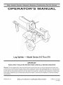 1
1
-
 2
2
-
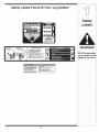 3
3
-
 4
4
-
 5
5
-
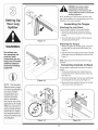 6
6
-
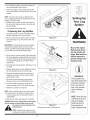 7
7
-
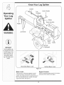 8
8
-
 9
9
-
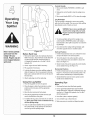 10
10
-
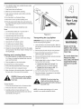 11
11
-
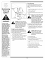 12
12
-
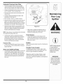 13
13
-
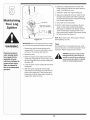 14
14
-
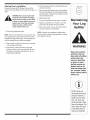 15
15
-
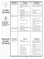 16
16
-
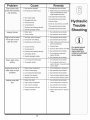 17
17
-
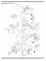 18
18
-
 19
19
-
 20
20
-
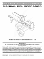 21
21
-
 22
22
-
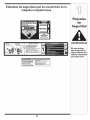 23
23
-
 24
24
-
 25
25
-
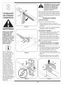 26
26
-
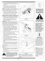 27
27
-
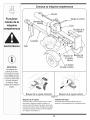 28
28
-
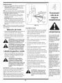 29
29
-
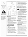 30
30
-
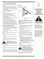 31
31
-
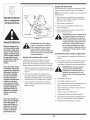 32
32
-
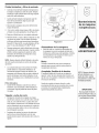 33
33
-
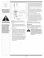 34
34
-
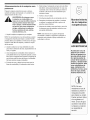 35
35
-
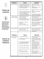 36
36
-
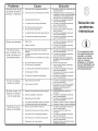 37
37
-
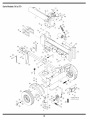 38
38
-
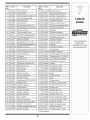 39
39
-
 40
40


MTD 510 series El manual del propietario
- Categoría
- Partidores de troncos
- Tipo
- El manual del propietario
- Este manual también es adecuado para
en otros idiomas
- English: MTD 510 series Owner's manual
Artículos relacionados
-
MTD 24777614 El manual del propietario
-
MTD 24BF570L099 El manual del propietario
-
-
-
-
-
-