Falmec IS27MURNEWYORK El manual del propietario
- Categoría
- Campanas de cocina
- Tipo
- El manual del propietario

Futuro
Futuro
INSTRUCTIONS BOOKLET
BEDIENUNGSSANLEITUNG
LIVRET D’INSTRUCTIONS
MANUAL DE INSTRUCCIONES
ИНСТРУКЦИЯ ПО ЭКСПЛУАТАЦИИ
INSTRUCJE OBSŁUGI
LIBRETTO ISTRUZIONI
Cod. 110030251 (CAPPE CLASSICHE)

Gentile Signora/Signore, congratulazioni!
Lei ha acquistato una cappa di prestigio e di sicura qualità. Perché Lei possa ottenere
le migliori prestazioni, Le suggeriamo di seguire con attenzione le istruzioni per l’uso e
manutenzione che troverà in questo libretto; inoltre, per ordinare i filtri di ricambio al
carbone attivo utilizzi l’apposito tagliando che troverà allegato alla copertina.
Dear Sir/Madam, congratulations!
You have purchased a prestigious range hood of guaranteed quality. For best results, we
suggest that you carefully follow the operating and maintenance instructions provided in this
booklet; in addition, to order spare charcoal filters, use the special coupon on the cover.
Verehrte Kundin, verehrter Kunde
Kompliment! Sie haben eine qualitativ hochwertige Dunstabzugshaube erworben. Um ihre
Leistungsfähigkeit optimal nutzen zu können, sollten Sie die beiliegende Gebrauchs- und
Wartungsanleitung sorgfältig durchlesen und befolgen. Für die Bestellung der Ersatz-
Aktivkohlefilter verwenden Sie bitte den Coupon, der dem Deckblatt beiliegt.
Chère Madame/Cher Monsieur, félicitations!
Vous venez d’acheter une hotte haut de gamme. Pour en tirer les performances les
meilleures veuillez lire avec attention le mode d’emploi et la maintenance que vous trouvez
dans ce manuel ; pour commander les filtres de rechange au carbone actif veuillez vous
servir du coupon annexé à la couverture.
Enhorabuena Señora/Señor!
Ha comprado una campana extractora de prestigio y calidad segura. Para que pueda
obtener las mejores prestaciones, le sugerimos seguir con atención las instrucciones
contenidas en este manual para el uso y el mantenimiento. Para pedir los filtros de recambio
de carbón activo, utilice el cupón adjunto a la cubierta.
Ç˚ ÔËÓ·ÎË ÔÒÚËÊÌÓ Ë ‚˚ÒÓÍÓ͇˜ÒÚ‚ÌÌÓ ‚˚ÚflÊÌÓ ÛÒÚÓÈÒÚ‚Ó. ÑÎfl ÚÓ„Ó,
˜ÚÓ·˚ ÓÌÓ ‰‡‚‡ÎÓ Ì‡ËÎÛ˜¯Ë ÁÛθڇÚ˚, ÍÓÏ̉ÛÏ ‚ÌËχÚθÌÓ ÒΉӂ‡Ú¸
ËÌÒÚÛ͈ËflÏ ÔÓ ˝ÍÒÔÎÛ‡Ú‡ˆËË Ë ÛıÓ‰Û, ÍÓÚÓ˚ ‚˚ Ì‡È‰Ú ‚ ˝ÚÓÏ ËÁ‰‡ÌËË;
ÍÓÏ ÚÓ„Ó, ‰Îfl Á‡Í‡Á‡ Á‡Ô‡ÒÌ˚ı ÙËθÚÓ‚ ̇ ‡ÍÚË‚ËÓ‚‡ÌÌÓÏ Û„Î ËÒÔÓθÁÛÈÚ
ÒԈˇθÌ˚È Ú‡ÎÓÌ, ÍÓÚÓ˚È ‚˚ ÏÓÊÚ Ì‡ÈÚË ÔËÍÔÎÌÌ˚Ï Í Ó·ÎÓÊÍ.
Szanowni Państwo
Gratulujemy!
Zakupiliście prestiżowy okap kuchenny o gwarantowanej jakości. Dla uzyskania
najlepszych wyników zalecamy, by starannie przestrzegać instrukcji obsługi i
konserwacji zawartych w tej broszurze. Ponadto, do zamawiania zapasowych fi ltrów
z węglem drzewnym, wykorzystywać specjalny kupon załączony na okładce.

1
650 mm
(25,6”)
650 mm
(25,6”)
Fig. C1
MIRABILIA PARETE/WALL
650 mm
(25,6”)
650 mm
(25,6”)
SUCTION
VERSION
RECIRCULATION
VERSION
Fig. C2
MIRABILIA ISOLA/ISLAND

2
Step 1
Step 2
Step 3
MIRABILIA PARETE/WALL
Predisposizione solo per versione con evacuazione posteriore
Only for back outlet version
Vista posteriore Mirabilia Wall / Rear view Mirabilia Wall
226,1
280,5
155

3
Fig. H3

4
X 300
A
B
C
E
D
F
G
H
V2
V1
Fig. O1
Fig. O2
Fig. O3
Fig. O4
MIRABILIA PARETE/WALL

5
A
B
A (1 : 1)
V 1
B (1 : 1)
B
B 1
ISTRUZIONI MONTAGGIO/SMONTAGGIO VETRI
MOUNTING INSTRUCTIONS FOR THE GLASSES
MIRABILIA 67 - MIRABILIA 97
ISOLA/ISLAND 67
ISOLA/ISLAND 67 CENTRAL CHIMNEY
MIRABILIA ISOLA/ISLAND 85
Fig. O5

6
H1
H
H2
Ø8
Ø8
C
C1
V1
V2
V3
A
Fig. O6
Fig. O8
Fig. O9
Fig. O7
V4
O7A
O7B
V4
MIRABILIA ISOLA/ISLAND 67

7
C2
H1
H
H2
Ø8
Ø8
C1
C
V1 (x4)
Fig. 1a
Fig. 1b
H1= 650 mm (25,6”)
V2 (x8)
C+C1
V3(x4)
A
F
D+E
MIRABILIA ISOLA/ISLAND 85
ISOLA/ISLAND 67 CENTRAL CHIMNEY
Fig. 1 Fig. 2

8
V3
V3
F
3a
3a
3d
3d
3c
3e
3f
3g
V3 (x4)
V5 (x2)
3i
3a
3b
V4 (x4)
MIRABILIA ISOLA/ISLAND 85 - ISOLA/ISLAND 67 CENTRAL CHIMNEY
Fig. 3

9
I
LIBRETTO ISTRUZIONI
AVVERTENZE
A
È molto importante che questo libretto istruzioni sia conservato insieme al-
l’apparecchiatura per qualsiasi futura consultazione.
Se l’apparecchio dovesse essere venduto o trasferito ad un’altra persona,
assicurarsi che il libretto venga fornito assieme, in modo che il nuovo utente
possa essere messo al corrente del funzionamento della cappa e delle avver-
tenze relative.
Queste avvertenze sono state redatte per la vostra sicurezza e per quella degli
altri, Vi preghiamo, dunque, di volerlo leggere attentamente prima d’installare
e di utilizzare l’apparecchio.
Questo apparecchio non deve essere utilizzato da bambini o persone infermi
a meno che non siano adeguatamente controllate da persone responsabili che
si assicurino che l’apparecchio sia utilizzato in sicurezza.
I bambini devono essere controllati da persona responsabile per assicurarsi
che non giochino con l’apparecchio.
Il lavoro di installazione deve essere eseguito, da installatori competenti e
qualificati, secondo le norme in vigore.
Se il cavo di alimentazione è danneggiato, esso deve essere sostituito dal
costruttore o dal suo servizio assistenza tecnica o comunque da una persona
con qualifica similare, in modo da prevenire ogni rischio.
Ogni eventuale modifica che si rendesse necessaria all’impianto elettrico per
installare la cappa dovrà essere eseguita solo da persone competenti.
È pericoloso modificare o tentare di modificare le caratteristiche di questo
impianto. In caso di riparazioni o mal funzionamento dell’apparecchio, non
tentare di risolvere da soli il problema.
Le riparazioni effettuate da persone non competenti possono provocare danni.
Per eventuali interventi rivolgersi ad un Centro Assistenza Tecnica autorizzato
ad eseguire parti di ricambio.
Controllare sempre che tutte le parti elettriche, (luci, aspiratore), siano spente
quando l’apparecchio non viene usato. Leggere tutto il libretto istruzioni pri-
ma di effettuare operazioni sulla cappa.
L’utilizzo della cappa non può essere diverso da quello di aspiratori di fumi di
cottura su cucine domestiche.
Qualsiasi utilizzo diverso da questo solleva il costruttore da qualsiasi respon-
sabilità.
Il peso massimo complessivo di eventuali oggetti posizionatio appesi (ove
previsto) sulla cappa non deve superare 1,5 Kg.
Dopo l’installazione delle cappe in acciaio inox bisogna eseguire la pulizia
della stessa per rimuovere i residui di collante protettivo e le eventuali mac-
chie di grasso o oli.
Per questa operazione il costruttore raccomanda l’utilizzo delle salviette in
dotazione, disponibili anche in acquisto.
L’utilizzo di altre tipologie di detergenti solleva il costruttore dalla responsa-
bilità sui danni che ne potrebbero derivare.

10
CARATTERISTICHE TECNICHE
B
I dati tecnici dell’elettrodomestico sono riportati su delle targhette, posiziona-
te all’interno della cappa.
INSTALLAZIONE
C
(parte riservata solo a persone qualificate per il montaggio della cappa)
La distanza minima: distanza fra la superficie di supporto dei recipienti di
cottura sul dispositivo di cottura e la parte più bassa della cappa da cucina.
Quando la cappa da cucina è posta su un apparecchio a gas, questa distanza
deve essere almeno 65 cm (vedi figura C1/C2). Se le istruzioni del piano di
cottura a gas specificano una distanza maggiore, bisogna tenerne conto.
Nella versione aspirante il tubo di uscita dei fumi deve avere un diametro non
inferire a quello del raccordo della cappa.
Nei tratti orizzontali il tubo deve avere una leggera inclinazione (10% circa)
verso l’alto per convogliare l’aria all’esterno dell’ambiente.
Ridurre al minimo le curve, verificare che i tubi abbiano una lunghezza mini-
ma indispensabile.
Rispettare le norme vigenti sullo scarico dell’aria all’esterno.
In caso di utilizzo contemporaneo di altre utenze (caldaie, stufe, caminetti,
ecc.) alimentate a gas o con altri combustibili, provvedere ad una adeguata
ventilazione del locale in cui avviene l’aspirazione dei fumi, secondo le norme
vigenti.
Istruzioni di montaggio: vedi sez. “O” del presente manuale.
ALLACCIAMENTO ELETTRICO
D
(parte riservata solo a persone qualificate per l’allacciamento)
ATTENZIONE!
Prima di effettuare qualsiasi operazione all’interno della cappa scollegare
l’apparecchio dalla rete elettrica.
Assicurarsi che non vengano scollegati o tagliati fili elettrici all’interno della
cappa; nel caso si verifichino tali situazioni contattare il centro assistenza più
vicino. Per l’allacciamento elettrico rivolgersi a personale qualificato.
Il collegamento deve essere eseguito in conformità con le disposizioni di
legge in vigore. Controllare che la valvola limitatrice e l’impianto elettrico
possano sopportare il carico dell’apparecchio (vedere targhetta caratteristiche
tecniche al punto B). Alcuni tipi di apparecchi possono essere dotati di cavo
senza spina; in questo caso, la spina da utilizzare deve essere dei tipo “nor-
malizzato” tenendo conto che:
- il filo giallo-verde deve essere utilizzato per la messa a terra,
- il filo blu deve essere utilizzato per il neutro,
- il filo marrone deve essere utilizzato per la fase, il cavo non deve entrare in
contatto con parti calde aventi temperature superiori a 70 °C.
- montare sul cavo di alimentazione una spina adatta al carico e collegarla ad
una adeguata spina di sicurezza.

11
Se un apparecchio fisso non è provvisto di cavo di alimentazione e di spina, o
di altro dispositivo che assicuri la disconnessione dalla rete, con una distanza
di apertura dei contatti che consenta la disconnessione completa nelle condi-
zioni della categoria di sovratensione III, le istruzioni devono indicare che tali
dispositivi di disconnessione devono essere previsti nella rete di alimentazio-
ne conformemente alle regole di installazione.
Il cavo di terra giallo/verde non deve essere interrotto dall’interruttore.
Prima di collegare l’apparecchio alla rete elettrica, controllare che:
- la tensione d’alimentazione corrisponda a quella indicata dalla targhetta
caratteristiche tecniche.
- la presa di terra sia corretta e funzionale.
- l’impianto di alimentazione sia munito di efficace collegamento di terra se-
condo le norme vigenti.
- la presa o l’interruttore omnipolare usati siano facilmente raggiungibili con
l’apparecchiatura installata.
La casa costruttrice declina ogni responsabilità nel caso le norme di sicurezza
non vengano rispettate.
E
CAPPA DI VERSIONE
AD EVACUAZIONE ESTERNA (aspirante)
In questa versione i fumi e i vapori della cucina vengono convogliati verso
l’esterno attraverso un tubo di scarico.
Il convogliatore di scarico che sporge sulla parte superiore della cappa de-
ve essere collegato con un tubo che conduce i fumi e i vapori in una uscita
esterna.
In questa versione vanno tolti i filtri al carbone attivo se esistenti; per l’estra-
zione vedere istruzioni al punto F. Quando la cappa da cucina viene utilizzata
contemporaneamente ad altri apparecchi che impiegano gas o altri combu-
stibili, il locale deve disporre di sufficiente ventilazione secondo le norme
vigenti.
Deviazione per la Germania:
Quando la cappa da cucina e apparecchi alimentati con energia diversa da
quella elettrica sono in funzione simultaneamente, la pressione negativa nel
locale non deve superare i 4 Pa (4 x 10⁻⁵ bar).
F
CAPPA DI VERSIONE
A RICICLO INTERNO (filtrante)
In questa versione l’aria passa attraverso i filtri di carbone attivo per essere
purificata e viene riciclata nell’ambiente cucina.
Controllare che i filtri al carbone attivo siano montati sul motore, in caso ne-
gativo applicarli come indicato nelle istruzioni al punto H.
Se la cappa viene predisposta in versione filtrante rimuovere la valvola di non
ritorno montata sul raccordo di uscita del motore.

12
Per il miglior rendimento si consiglia di utilizzare la terza velocità in presenza
di forti odori e vapori, la seconda velocità nelle condizioni normali, la prima
velocità per mantenere l’aria pulita con bassi consumi di energia elettrica.
Si consiglia di mettere in funzione la cappa quando si inizia a cuocere e man-
teneria in funzione fino alla scomparsa degli odori.
G
FUNZIONAMENTO
1. PULSANTIERA ELETTRONICA
Pulsante luce
• ON: luce accesa (pulsante illuminato);
• OFF: luce spenta;
Pulsante -
Premendo il tasto si riduce la velocità del motore.
La velocità 1, 2 e 3 è visualizzata dal n° di led accesi escluso led luce e
timer.
Pulsante +
Premendo il tasto si incrementa la velocità del motore.
La velocità 1,2 e 3 è visualizzata dal n° di led accesi escluso led luce e ti-
mer.
(Nella versione a 4 velocità il tasto + presenta una luce intermittente. La 4°
velocità o intensiva è temporizzata e dopo circa 15 minuti il motore passa
automaticamente in 3° velocità).
Pulsante modalità
Funzione: accensione e spegnimento motore cappa.
La funzione velocità desiderata permette di avviare il motore con l’ultima
velocità selezionata prima del precedente spegnimento.
Optional: versione con radiocomando (disponibile solo su alcune versioni).
AVVERTENZE (versione con radiocomando):
Posizionare l’apparecchio lontano da sorgenti di onde elettromagnetiche
che potrebbero interferire con l’elettronica della cappa.
Distanza massima di funzionamento 5 metri. Tale distanza può variare in
difetto in funzione delle interferenze elettromagnetiche di altri apparecchi.
Pulsante luce del telecomando: on/off luce.
Pulsante – e + decremento/incremento velocità (per avviare il motore pre-
mere indifferentemente tasto + o in tasto -.
Pulsante timer: vedi istruzione sottostante.
Pulsante timer e saturazione filtri
- Questa funzione permette lo spegnimento automatico della cappa dopo
15 minuti di funzionamento alla velocità precedentemente impostata (pul-
sante con luce intermittente).
- Dopo circa 30 ore di funzionamento il pulsante propone il lavaggio dei fil-
tri metallici (pulsante illuminato di rosso). Per disattivare l’allarme preme-
re il pulsante timer per qualche secondo fino allo spegnimento della luce
rossa. Successivamente spegnere la cappa e riaccenderla per verificare
l’annullamento dell’allarme.

13
2. DIMMER
Sul fondo della cappa è posizionato un regolatore (dimmer) di intensità
luminosa per le luci di atmosfera.
a) Dimmer a manopola: girare la manopola in senso orario per aumentare
o in senso antiorario per ridurre, l’intensità luminosa. Per spegnere com-
pletamente la luce girare in senso antiorario fino al “clic” di OFF, ripetere
l’operazione all’inverso per la posizione ON.
b) Dimmer a soft touch: tenere premuto il tasto per aumentare o ridurre l’in-
tensità luminosa.
c) Dimmer con funzioni integrate nella tastiera: con motore spento e con una
pressione lunga tasto luce (2 secondi) della tastiera si accede alla modalità
modifica intensità luce di atmosfera (lampade ad incandescenza). Agendo
sui tasti + e – si regola l’intensità della luce. Con motore avviato la pres-
sione lunga del tasto accende o spegne la luce di atmosfera.
Per sostituire la lampada ad incandescenza:
1) accertarsi che la cappa sia scollegata dalla rete elettrica;
2) rimuovere i vetri decorativi (vedi sez. O);
3) sostituire la lampadina con una dello stesso modello di quella originale
(max. 25W);
4) rimontare i vetri (vedi fig. O5).
FILTRI ISTRUZIONI PER L’ESTRAZIONE E LA SOSTITUZIONE
H
1. FILTRI METALLICI
- Aprire il pannello (vedi fig. H3). Per rimuovere il filtro metallico antigrasso
agire sulla maniglia A.
A
2. FILTRI AL CARBONE ATTIVO
Per la sostituzione dei filtri al carbone attivo si proceda come segue: toglie-
re i filtri metallici come indicato sopra. A questo punto si accede facilmen-
te ai due filtri che sono agganciati sul lato dx e sx del convogliatore.
Per il montaggio/sostituzione vedi figura.
Per ordinare i nuovi filtri servirsi del tagliando allegato al libretto o rivol-
gersi al distributore.

14
3. PANNELLO REMOVIBILE
Per rimuovere il pannello seguire l’istruzione in fig. H3
ILLUMINAZIONE MONTAGGIO E SOSTITUZIONE
I
FARETTO
Per sostituire la lampada del “Square halogen light”:
a) Accertarsi che l’apparecchio sia scollegato dalla rete elettrica.
b) Aprire completamente il pannello fino ad un angolo di 90° (vedi figura) pre-
mendo su PUSH
c) Sostituire la lampada con una analoga (alogena max 20 W, 12 Volt attacco
G4).
d) Richiudere i pannello. Se il pannello non si richiude correttamente ripetere
l’operazione al punto b.
Square halogen light
MANUTENZIONE E PULIZIA
L
Una costante manutenzione garantisce un buon funzionamento ed un buon
rendimento nel tempo. Particolari attenzioni vanno rivolte ai filtri metallici anti-
grasso ed ai filtri al carbone attivo, infatti la pulizia frequente dei filtri e dei loro
supporti garantisce che sulla cappa non si accumulino grassi che sono perico-
losi per la facilità di incendio.
1. FILTRI ANTIGRASSO METALLICI
Hanno la funzione di trattenere le particelle grasse in sospensione, pertanto
si consiglia di lavarli ogni mese in acqua calda e detersivo evitando di pie-
garli. Attendere che siano ben asciutti prima di rimontarli.
Per lo smontaggio e montaggio vedi istruzioni al punto H1. Si raccomanda
costante frequenza nell’operazione.
2. FILTRI AL CARBONE ATTIVO

15
Hanno la funzione di trattenere gli odori presenti nel flusso d’aria che li
attraversa. L’aria depurata per successivi passaggi attraverso i filtri viene
rimessa nell’ambiente cucina. l filtri al carbone attivo non possono essere
lavati e vanno sostituiti mediamente ogni 3-4 mesi (dipende poi dall’uso).
Per la sostituzione dei filtri al carbone attivo seguire le istruzioni come al
punto H2.
3. PULIZIA ESTERNA
La pulizia della cappa va eseguita usando un panno umido con detersivo
liquido neutro o con alcool denaturato.
Nel caso di materiale con trattamento antimpronta (Fasteel) eseguire la pu-
lizia solo con acqua e sapone neutro utilizzando un panno morbido avendo
cura di risciacquare e asciugare accuratamente. Non si devono utilizzare
prodotti contenenti sostanza abrasive, panni con superfici ruvide o panni
comunemente in commercio per la pulizia dell’acciaio. L’utilizzo di sostanze
abrasive e panni ruvidi danneggerà irreparabilmente il trattamento superfi-
ciale dell’acciaio. Conseguenza diretta del non rispetto di tali avvertenze sarà
il deterioramento irreversibile della superficie dell’acciaio.
Tali avvertenze dovranno essere conservate insieme al libretto istruzioni
della cappa. Il produttore declina ogni responsabilità qualora non vengano
rispettate tali istruzioni.
4. PULIZIA INTERNA
É vietata la pulizia di parti elettriche o parti relative al moto re all’interno della
cappa, con liquidi o solventi.
Non usare prodotti contenenti abrasivi.
Effettuare tutte queste operazioni scollegando preven tivamente l’apparecchio
dalla rete elettrica.
SICUREZZA AVVERTENZE
M
L’impianto elettrico è munito di collegamento a terra secondo le norme di sicu-
rezza internazionali; è inoltre conforme alle normative Europee sull’antidisturbo
radio. Non collegare l’apparecchio a condotti di scarico dei fumi prodotti dalla
combustione (caldaie, caminetti,ecc). Verificare che la tensione di rete corri-
sponda a quella riportata dalla targhetta posta all’interno della cappa.
La distanza minima di sicurezza tra il piano di cottura e la cappa deve essere di
almeno 65 cm. Non fare cotture a fiamma “libera” sotto la cappa. Controllare
le friggitrici durante l’uso: I’olio surriscaldato potrebbe infiammarsi.
- Assicurarsi che vi sia una adeguata ventilazione nella stanza se la cappa è
utilizzata con altri apparecchi che utilizzano combustibili come gas o altro.
- Non accendere fiamme libere sotto la cappa.
- Non collegare l’apparecchio a condotti di scarico dei fumi prodotti dalla com-
bustione (caldaie, caminetti, ecc).
- Assicurarsi che tutte le normative vigenti sullo scarico dell’aria all’esterno del
locale siano rispettate prima dell’utilizzo della cappa.
Prima di procedere a qualsiasi operazione di pulizia o di manutenzione, disin-
serire l’apparecchio togliendo la spina o agendo sull’interruttore generale. La
casa costruttrice declina ogni responsabilità per eventuali danni che possano,
direttamente o indirettamente, essere causati a persone, cose ed animali do-
mestici in conseguenza alla mancanza di tutte le prescrizioni indicate nell’ap-
posito libretto istruzioni e concernenti, specialmente, le avvertenze in tema di
installazione, uso e manutenzione dell’apparecchio.

16
GARANZIA
N
La sua nuova apparecchiatura è coperta da garanzia. Le condizioni di garanzia
sono riportate per esteso sull’ulti ma pagina di copertina di questo libretto.
La casa costruttrice non risponde delle possibili ine sattezze, imputabili ad errori
di stampa o di trascrizio ne, contenute nel presente libretto. Si riserva di appor-
tare ai propri prodotti quelle modifiche che ritenesse necessarie o utili, anche
nell’interesse dell’utenza, senza pregiudicare le caratteristiche essenziali di fun-
zionalità e di sicurezza.
MONTAGGIO CAPPA
O
O1 - MONTAGGIO MIRABILIA PARETE
Fase 1
- Appoggiare alla parete la barra di sostegno (A-Fig. O1), ad un’altezza dal pia-
no cottura determinata dalla somma delle quote X+300 mm.
- Controllare con una bolla di livello l’allineamento orizzontale e segnare alle
estremità della barra n° 2 punti di foratura.
- Forare, inserire n° 2 tasselli ad espansione ø 8mm e fissare la barra con le
relative viti.
Fase 2
- Agganciare la cappa alla barra di sostegno (Fig. O2).
- Regolare l’allineamento della cappa tramite le viti delle attaccaglie:
La vite superiore (B) regola la distanza dalla parete, quella inferiore (C) lo
scorrimento verticale.
Fase 3
- Per evitare lo sganciamento della cappa dovuto ad una pressione sottostan-
te, fissarla alla parete con le staffette in dotazione (fig. O3).
- Inserire sul raccordo(D) il tubo (E).
Fase 4
- Infilare nell’elemento (G) la prolunga (H), facendola scorrere fino a raggiun-
gere l’altezza desiderata.
- Trovata la posizione ottimale, fissare la prolunga al camino mediante le viti
(V1) in dotazione;
- Fissare l’assieme camino+prolunga alla cappa mediante le 6 viti V2.
- Eseguire il montaggio dei vetri sulla cappa (fig. O5)
O2 - MONTAGGIO MIRABILIA ISOLA 67
Fase 1
- Individuare l’altezza (min.H1=65 cm) desiderata per il posizionamento della
cappa.
- Far scorrere i tralicci (C) e (C1) fino ad ottenere l’altezza desiderata (H2), suc-
cessivamente bloccarli con 8 viti (V2) autofilettanti (Fig.O6).
Fase 2
- Infilare la prolunga sul camino (Fig. O6).
- Nel caso di versione aspirante: individuare l’altezza ottimale del tubo rigido o
flessibile di scarico dei fumi e collegarlo al raccordo motore.
Fase 3
- Alzare la cappa agganciandola alle 4 viti metriche M5 (V4) pre-avvitate al tralic-

17
cio (centrare i fori Ø11 sull’asola dell’intercamera e traslarla lateralmente)(Fig.
O7a).
- Serrare definitivamente le 4 viti M5 (V4) (Fig. O7b).
- Eseguire il collegamento del tubo al raccordo del foro di scarico del soffitto
(nel caso di versione aspirante).
- Eseguire il collegamento elettrico solo dopo aver disinserito l’alimentazione
elettrica.
- Fissare la prolunga al traliccio tramite le 4 viti metriche M4 (V3) (Fig. O8).
- Utilizzare gli elementi supporto prolunga (A) (Fig. O9) solo nel caso non venga
usato il traliccio superiore, oppure nel caso di un contro-soffitto.
- Eseguire il montaggio dei vetri sulla cappa (fig. O5).
O3 - MONTAGGIO MIRABILIA ISOLA 85/ISOLA 67 CENTRAL
CHIMNEY
Fase 1
- Individuare l’altezza (H1=65) desiderata per il posizionamento della cappa.
- Far scorrere i tralicci (C) e (C1) fino ad ottenere l’altezza desiderata (H2), suc-
cessivamente bloccarli con 8 viti (V2) autofilettanti (Fig.1a).
- Fissare il traliccio (C) al soffitto utilizzando 4 fischer da Ø 8 e relative viti (V1)
(Fig.1b).
Fase 2
- Infilare la prolunga sul camino e bloccarli tra loro con scotch di carta (Fig. 2).
- Fissare l’assieme camino-prolunga (D+E) al traliccio (C) tramite le 4 viti metri-
che M4 (V3) inserite nei fori esistenti senza bloccarle definitivamente (Fig. 2).
- Nel caso di versione aspirante: individuare l’altezza ottimale del tubo rigido o
flessibile di scarico dei fumi (F) e collegarlo al raccordo motore.
Fase 3
- Alzare la cappa agganciandola alle 4 viti metriche M5 (V4) pre-avvitate al tralic-
cio (C) (centrare i fori Ø11 sull’asola dell’intercamera e traslarla lateralmente)
(Fig. 3a).
- Serrare definitivamente le 4 viti M5 (V4) (Fig. 3b).
- Togliere lo scotch di carta (Fig. 3c), togliere le 4 viti metriche M4 (V3) avvitate
precedentemente sul traliccio (Fig. 3d) e far scorrere verso il basso l’assieme
camino-prolunga (Fig. 3e).
- Eseguire il collegamento del tubo al raccordo del foro di scarico del soffitto
(nel caso di versione aspirante) (Fig. 3f).
- Eseguire il collegamento elettrico solo dopo aver disinserito l’alimentazione
elettrica.
- Fissare la prolunga al traliccio (C) tramite le 4 viti metriche M4 (V3), senza
bloccarle definitivamente (Fig. 3g).
- Bloccare definitivamente la prolunga sul traliccio (C) serrando le 4 viti metri-
che M4 (V3).
- Bloccare il camino tramite 2 viti autofilettanti (V5) (Fig. 3i).
- Utilizzare gli elementi supporto prolunga (A) (Fig. 2) solo nel caso non venga
usato il traliccio superiore, oppure nel caso di un contro-soffitto.
- Eseguire il montaggio dei vetri sulla cappa (fig. O5).

18
GB
INSTRUCTIONS BOOKLET
WARNINGS
A
This instruction booklet must be kept together with the appliance for future
reference. If the appliance is sold or consigned to other parties, check that
the booklet is supplied with it, to ensure that the new user has the correct
information on the operation of the range hood and is aware of the warnings.
These warnings have been provided for the your safety and the safety of oth-
ers. As a result, please read them carefully before installing and operating the
appliance.
This appliance is not intended for use by young children or infirm persons un-
less they have been adequately supervised by a responsible person to ensure
that they can use the appliance safely. Young children should be supervised to
ensure they do not play with the appliance.
The appliance must be installed by qualified personnel, in accordance with
the standards in force. If the supply cord is damaged, it must be re-placed
by the manufacturer, its service agent or similarly qualified persons in order
to avoid a hazard. Any modifications that may be required to the electrical
system for the installation of the range hood must only be made by qualified
electricians.
It is dangerous to modify or attempt to modify the characteristics of this sys-
tem. In the event of malfunctions or if repairs are required to the appliance,
do not attempt to solve the problems directly.
Repairs performed by unqualified persons may cause damage. For all repair
and other work on the appliance, contact an authorised service/spare parts
centre.
Always check that all the electrical parts (lights, exhaust device), are off when
the appliance is not being used. Read the entire instruction booklet before
performing any operations on the range hood.
The range hood must only be used for the exhaust of cooking fumes in home
kitchens. The manufacturer disclaims all liability for any other use of the ap-
pliance.
The maximum weight of any object placed above the hood, or hung to it (if
possible) must not exceed 1,5 kilos. After installing the stainless steel hood,
clean it in order to remove any residue of the protective glue, and stains of
grease or oil. The manufacturer recommends its cleaning cloth available for
purchase. The manufacturer accepts no liability in case of damage caused by
the use of different detergent types.
TECHNICAL SPECIFICATIONS
B
The technical data pertaining to the electric appliance The technical specifica-
tions of the appliance are shown on the rating plates located inside the range
hood.

19
INSTALLATION
C
(Section reserved for qualified installers of the range hood)
Minimum distance: distance between the pan supports of the cooker and the
bottom-most section of the hood. When the hood is positioned above a gas
equipment this minimum distance must be at least 65 cm (see picture C1/C2)
or even more, if this is specified in the instructions for use of the gas cooker.
In the outside exhaust version, the diameter of the fume discharge duct must
be no smaller than the range hood connection.
In the horizontal sections, the duct must slope slightly (around 10%) upwards,
so as to better convey the air outside of the room.
Avoid using angled pipes, make sure that the pipes are at least of the mini-
mum length.
Comply with the current regulations on air discharge into the atmosphere.
If a boiler, stove, fireplace, etc. that uses gas or other fuels is being used at
the same time, make sure the room where the fumes are extracted is well
ventilated, in compliance with the current regulations.
Mounting instruction: see section “O” of the booklet.
ELECTRICAL CONNECTIONS
D
(Section reserved for qualified installers)
WARNING!
Before doing any work inside the range hood, disconnect the appliance from
the mains power supply.
Check that the wires inside the range hood are not disconnected or cut; if this
is the case, contact your nearest service centre. The electrical connections
must be performed by qualified personnel.
The connections must be performed in compliance with the legal standards in
force. Check that the relief valve and the electrical system are able to support
the load of the appliance (see the technical specifications in point B).
Some types of appliance are supplied with a cable without plug; in this case,
“standardised” plugs must be used, keeping in mind that:
- the yellow-green wire must be used for the earth,
- the blue wire must be used for the neutral,
- the brown wire must be used for the phase; the cable must not come into
contact with hot parts (over 70°C).
- fit a plug that is suitable for the load to the power cable, and connect it to a
suitable power outlet.
For appliances that come supplied with cable and plug please ensure they are
plugged into a circuit suitable for this appliance.
Please refer to a qualifed person. (See technical specifications in point B).
The manufacturer declines all liability if the safety standards are not ob-
served.

20
E
RANGE HOOD WITH OUTSIDE
DISCHARGE (exhaust)
In this version, the fumes and steam from the kitchen are conveyed outside
through an exhaust duct.
The exhaust conveyor that protrudes from the upper part of the range hood
must be connected to a duct that carries the fumes and steam outside. In this
version, the charcoal filters, if fitted, should be removed; to do this, see the in-
structions in point F. There must be adequate ventilation of the room when the
range hood is used at the same time as appliances burning gas or other fuels,
according to the standard.
Deviation for Germany:
When the range hood and appliances supplied with energy other than electric-
ity are simultaneously in operation, the negative pressure in the room must
not exceed 4 Pa (4x10 E-5 bar).
F
RECIRCULATING RANGE
HOOD (with filter)
In this version, the air passes through charcoal filters for purification, and is
then recirculated back into the kitchen.
Check that the charcoal filters are fitted to the motor, and if not, install them as
described in the instructions in point H.
If the hood is of filtering type, remove the non-return valve fitted at the motor’s
outlet.
For maximum efficiency, the third speed should be used when there are strong
odours or a lot of steam, the second speed in normal conditions, and the first
speed for keeping the air clean with minimum energy consumption. The range
hood should be switched on when starting to cook, and left on until the odours
disappear.
G
OPERATION
1. ELECTRONIC CONTROL PANEL
Light pushbutton
- ON: light on (the pushbutton is lit);
- OFF: light off;
Pushbutton -
Press to reduce motor speed
Speed 1, 2 and 3 are indicated by the number of LEDs that light up (exclud-
ing the light and the timer LEDs).
Pushbutton +
Press to increase motor speed
Speed 1, 2 and 3 are indicated by the number of LEDs that light up (exclud-
ing the light and the timer LEDs). (In the 4-speed version the pushbutton
+ blinks. The fourth speed remains on for a set duration of time. After 15
minutes the motor returns to the third speed).

21
Mode pushbutton
Function: it turns hood motor on and off.
The function “desired speed” enables to start the motor at the speed that
was selected before the hood was last turned off.
Optional: version with remote control (some versions only).
WARNING:
Install the hood away from sources of electromagnetic waves, as these
could affect the correct operation of the electronic system.
Maximum operating distance: 5 metres. The maximum operating distance
could be less than 5 metres in case of electromagnetic interference by
other equipment.
Light pushbutton on remote control: light on/off.
– and + pushbutton: increase/decrease speed (to start the motor press
either the + or the – pushbutton).
Timer pushbutton: see instructions below.
Timer and ‘filter clogged’ alarm pushbutton
- This function allows the automatic turning off of the hood after running
for 15 minutes at the speed previously set (the pushbutton shows a flicker-
ing light).
- After about 30 hours of running the pushbutton indicates the need for
washing the metal filters (the pushbutton shows a solid red light). To dis-
able the alarm press the pushbutton for a few seconds until the red light
turns off. Then turn the hood off and on again to check that the alarm has
disappeared.
2. DIMMER
At the bottom of the hood there is a dimmer for the adjustment of the
ambient lights.
a) Knob dimmer: turn the knob clockwise to increase light intensity and an-
ticlockwise to decrease it. To turn the light off turn the knob anticlockwise
till the OFF click. To turn it on, turn the knob clockwise till the ON click.
b) Soft- touch dimmer: keep the button pressed to increase or decrease light
intensity.
c) Dimmer with functions integrated in the control panel: with the motor
turned off and by holding down the light button on the control panel for a
while (2 seconds) you automatically decide on the mode of the light inten-
sity (incandescent light globe). By pressing on + and on – you can adjust
the intensity of the light. With the motor running, the prolonged pressing
of the button down, will turn the atmosphere light on or off.
To replace the incandescent light bulb:
1) make sure that the hood is disconnected from the power supply;
2) remove the decorative glass (refer to section O);
3) fit a new light bulb of the same model (max. 25W);
4) replace the decorative glass (refer to fig. O5).

22
FILTERS REMOVING AND REPLACING’S INSTRUCTIONS
H
1. METAL FILTERS
Open the panel (see fig. H3). Use handle A to remove the metal grease
filter.
A
2. CHARCOAL FILTERS
To replace the charcoal filters, proceed as follows: remove the metal filters
as described above. The two filters located at the ends of the motor can
now be easily accessed.
To install the new fi lters see picture.
To order new filters, use the coupon enclosed with this booklet or provided
by the distributor.
3. REMOVABLE PANEL
Follow the instructions on fig. H3 to remove the panel.
LIGHTING ASSEMBLY AND REPLACEMENT
I
SPOTLIGHT
How to replace a square halogen light:
a) Check that the equipment is disconnected from the power supply.
b) Open the panel completely till 90° (see figure) pressing the PUSH button
c) Replace the lamp with a similar one (halogen, max 20 W, 12 Volt, G4 con-
nection).
d) Close the panel. If the panel does not close correctly repeat the operation
at point b.

23
Square halogen light
MAINTENANCE AND CLEANING
L
Constant maintenance ensures the correct operation and efficiency of the ap-
pliance over time. Special attention should be paid to the metal grease-trap-
ping filters and the charcoal filters. Frequent cleaning of the filters and their
supports will ensure that fats and grease do not accumulate on the range
hood, with the consequent risk of fire.
1. METAL GREASE-TRAPPING FILTERS
These trap the fat and grease particles suspended in the air, and therefore
should be washed every month in hot water and detergent, without bend-
ing them. Wait until they are completely dry before repositioning them.
To remove and replace these filters, see the instructions in point H1. This
operation should be performed at regular intervals.
2. CHARCOAL FILTERS
These trap the odours present in the stream of air that passes through
them. The air is purified by passing a number of times through the filters
and being recirculated into the kitchen. The charcoal filters cannot be
cleaned, and should be replaced on average every 3-4 months (according
to use). To replace the charcoal filters, see the instructions in point H2.
3. CLEANING THE OUTSIDE OF THE APPLIANCE
The ouside of the range hhod should be cleaned using a damp cloth and
neutral liquid detergent or denatured alcohol.
In case of fingerprint-less finish (fasteel) clean only with water and neutral
soap using clean with a soft cloth, rinse and wipe dry thoroughly. Do not use
products that contain abrasive substances, rough cloths or cloths specifically
designed for cleaning steel. Using abrasive substances or rough cloths will
inevitably damage the finish of steel. The steel surface will be irrevocably
damaged if the instructions above are not complied with.
Keep these instructions together with the instructions for use of your hood.
The manufacturer accepts no liability for any damage caused by non-compli-
ance with the instructions above.
4. CLEANING THE INSIDE OF THE APPLIANCE
The electrical parts or parts of the motor assembly inside the range hood
must not be cleaned using liquids or solvents.
Do not use abrasive products. All the above operations must be performed
after having disconnected the appliance from the mains power supply.

24
SAFETY WARNINGS
M
The electrical system features an earth connection in compliance with interna-
tional safety standards; furthermore, it is compliant with the European standard
for electromagnetic compatibility.
Do not connect the appliance to flues (from boilers, fireplaces, etc.). Make sure
the mains voltage corresponds to the values on the rating plate located inside
the range hood. The minimum safety distance between the cooktop and the
range hood must be at least 65 cm.
Never cook on “open” flames under the range hood.
Check deep-fryers during use: superheated oil may be flammable.
- Ensure there is adequate ventilation of the room when the rangehood is used
at the same time as appliances burning gas or other fuels.
- Do not flambe under the rangehood
- The exhaust air must not be discharged into a flue which is used for exhaust-
ing fumes from appliances burning gas or other fuels.
- Ensure that all regulations concerning the discharge of exhaust air have been
fulfilled before you use the appliance.
Before performing any cleaning or maintenance operations, disconnect the ap-
pliance by unplugging it or using the main switch. The manufacturer disclaims
all liability for any damage that may be directly or indirectly caused to people,
things and animals due to the failure to follow all the instructions provided in
this booklet and above all the warnings relating to the installation, operation
and maintenance of the appliance.
WARRANTY
N
The new equipment is covered by warranty.
The warranty conditions are provided by the distributor.
The manufacturer is not liable for any inaccuracies in this booklet resulting
from printing or transcription errors. The manufacturer reserves the right to
modify its products as it considers necessary or in the interests of the user,
without compromising their essential safety and operating characteristics.
HOOD INSTALLATION
O
O1 - INSTRUCTIONS FOR WALL-MOUNTED MIRABILIA HOODS
Phase 1
- Place the support bar next to the wall (A-Fig. O1), at a height above the cook-
top which corresponds to X+300 mm.
- With a spirit level check that the bar is horizontal. Mark a point at each end
of the bar.
- Drill the holes, fit 2 ø8mm expansion joints and screw in the bar.
Phase 2
- Fit the hood to the support bar (Fig. O2).
- Adjust hood alignment with the relevant screws: The top screw (B) adjusts
the distance from the wall. The bottom screw (C) adjusts the vertical sliding
movement.

25
Phase 3
- To prevent the hood from detaching if pressure is exerted from beneath,
secure it to the wall with the brackets supplied (fig. O3).
- Fit pipe/hose (E) into (D).
Phase 4
- Slide the extension (H) into (G) till the desired height.
- When the extension is at the desired height, screw it onto the chimney with
the screws supplied (V1);
- Lock the chimney + extension onto the hood with 6 V2 screws.
- Fit the glass panels (fig. O5).
O2 - INSTRUCTIONS FOR MIRABILIA ISLAND 67
Phase 1
- Identify the desired height (H1=65 cm) of the hood.
- Slide the internal support frames (C) and (C1) till the desired height (H2),
then lock them with 8 self-tapping screws (V2) (Fig.O6).
Phase 2
- Fit the extension to the chimney (Fig. O6).
- If the hood is of extraction type: identify the desired height of the exhaust
pipe/hose and connect it to the motor connection.
Phase 3
- Lift the hood and hook it onto the 4 M5 metric screws (V4) pre-screwed to the
internal support frame (centre the Ø11 holes with the slot of the reinforce-
ment frame and move the frame sideways) (Fig. O7a).
- Tighten the 4 M5 screws (V4) (Fig. O7b).
- Connect the pipe/hose to the exhaust hole on the ceiling (it the hood is of
extraction type).
- Connect the electrical system after having disconnected the power supply.
- Fit the extension to the internal support frame with 4 M4 metric screws (V3),
(Fig. O8).
- Use extension brackets (A) (Fig. O9) only if the top internal support frame is
not used, or if there is a false ceiling.
- Fit the glass panels (fig. O5).
O3 - INSTRUCTIONS FOR MIRABILIA ISLAND 85/ISLAND 67
CENTRAL CHIMNEY
Phase 1
- Identify the desired height (H1=65) for the positioning of the hood.
- Slide the lattice-works (C) and (C1) to the desired height (H2), then block
them with the 8 self-threading screws (V2) (Fig.1a).
- Fasten the lattice-work (C) to the ceiling using the four Ø 8 expansion plugs
and relative screws(V1) (Fig.1b).
Phase 2
- Insert the extension on the flue and fasten them to each other with masking
tape (Fig. 2).
- Fasten the flue-extension assembly (D+E) to the lattice-work (C) with the 4
M4 metric screws (V3) inserted in the existing holes without tightening them

26
completely (Fig. 2).
- For suction version: identify the optimal height for the rigid or flexible ex-
haust pipe (F) and connect it to the motor connection.
Phase 3
- Raise the hood, hooking it onto the 4 M5 metric screws (V4) pre-tightened
to the lattice-work (C) (center the Ø11 holes on the slot of the inner liner and
move it laterally)(Fig. 3a).
- Completely tighten the 4 M5 screws (V4) (Fig. 3b).
- Remove the masking tape (Fig. 3c), remove the four M4 metric screws (V3)
previously tightened onto the lattice-work (Fig. 3d) and slide the flue-exten-
sion assembly downwards. (Fig. 3e).
- Connect the pipe to the connection of the ceiling discharge hole. (Fig. 3f).
- Make electrical connections only after having removed electrical power sup-
ply.
- Fasten the extension to the lattice-work (C) by means of the 4 M4 metric
screws (V3), without tightening them completely(Fig. 3g).
- Block the extension completely to the lattice-work (C) by screwing down the
4 M4 metric screws (V3).
- Block the flue with the 2 self-threading screws (V5) (Fig. 3i).
- Use the extension support elements(A) (Fig. 2) only if the upper lattice-work
is not used, or in the case of a false ceiling.
- Fit the glass panels (fig. O5).

27
D
BEDIENUNGSANLEITUNG
HINWEISE
A
Diese Bedienungsanleitung muss unbedingt zusammen mit dem Gerät auf-
bewahrt werden, um in Zukunft nachgeschlagen werden zu können.
Sollte das Gerät verkauft bzw. einer anderen Person übergeben werden, muss
die Bedienungsanleitung unbedingt mitgeliefert werden, damit der neue Benu-
tzer mit dem Betrieb der Dunstabzugshaube und den diesbezüglichen Hinwei-
sen vertraut werden kann.
Diese Hinweise sind für Ihre Sicherheit und die anderer Personen abgefasst
worden. Daher sollten Sie die Bedienungsanleitung vor der Installation und
Verwendung des Gerätes aufmerksam durchlesen.
Das Gerät darf nicht von Kindern bzw. Behinderten benutzt werden, es sei denn
diese werden von verantwortungsvollen Personen, die dafür Sorge tragen,
dass das Gerät sicher verwendet wird, überwacht.
Kinder müssen von einer von verantwortungsvollen Person überwacht werden,
damit sie nicht mit dem Gerät spielen.
Die Installation hat den geltenden Vorschriften gemäß von kompetenten, quali-
fizierten Installateuren durchgeführt zu werden.
Beschädigte Speisekabel sind vom Hersteller bzw. von dessen Kundenservice
bzw. von einer Person mit ähnlicher Qualifikation auszuwechseln, um Gefahren
vorzubeugen.
Eventuelle erforderliche Änderungen, die für die Installation der Dunsta-
bzugshaube an der elektrischen Anlage durchgeführt werden müssen, dürfen
ausschließlich von kompetenten Personen vorgenommen werden.
Es ist gefährlich, die Eigenschaften dieser Anlage abzuändern bzw. versuchen
abzuändern. Bei Reparaturen bzw. Betriebsstörungen des Gerätes nicht versu-
chen, das Problem alleine zu lösen.
Die Reparaturen, die von nicht kompetenten Personen durchgeführt werden,
können Schäden verursachen.
Sich für eventuelle Eingriffe an einen zugelassenen Kundenservice, der über die
geeigneten Ersatzteile verfügt, wenden.
Wenn das Gerät nicht benutzt wird, müssen alle elektrischen Teile (Beleuchtung,
Absaugvorrichtung) ausgeschaltet sein. Vor Durchführung von Arbeitsvorgän-
gen an der Dunstabzugshaube die Bedienungsanleitung lesen.
Die Dunstabzugshaube darf ausschließlich zum Absaugen des Dampfes, der
beim Kochen in einer Haushaltsküche entsteht, verwendet werden.
Bei anderen Einsätzen wird der Hersteller von jeder Haftung befreit.
Das Gesamtgewicht von Gegenständen, die eventuell auf die Dunstabzugshau-
be positioniert bzw. an diese gehängt werden (falls vorgesehen), darf höch-
stens 1,5 Kg betragen.
Nach der Installation von Edelstahlhauben muss man diese reinigen, um Schu-
tzkleberreste und eventuelle Fett- und Ölflecken zu entfernen.
Der Hersteller empfiehlt für doesen Arbeitsvorgang die Verwendung der mitge-
lieferten Reinigungstücher.
Die Verwendung anderer Reinigungsmittel befreit den Hersteller von jeder Haf-
tung für eventuelle auf deren Benutzung zurückzuführende Schäden.

28
TECHNISCHE MERKMALE
B
Die technischen Daten des Elektrogeräts sind an den Typenschildern im Innern
der Dunstabzugshaube angegeben.
INSTALLATION
C
(Dieser Abschnitt ist Fachpersonal mit der für die Montage der Dunstabzugshau-
be erforderlichen Qualifikation vorbehalten)
Der Mindestabstand: der Abstand zwischen der Aufliegefläche der Kochtöpfe
auf der Kochebene und dem unteren Dunstabzugshaubenteil. Wenn die Dun-
stabzugshaube über ein Gasgerät positioniert wird, muss dieser Abstand min-
destens 65 cm betragen (siehe Abb. C1/C2). Sollte in der Bedienungsanleitung
der Gaskochebene ein höherer Abstand angegeben sein, muss man diesen
berücksichtigen.
In der Abluftversion kann der Durchmesser des Rauchablasses nicht kleiner als
der des Dunstabzugshaubenanschlusses sein.
In den waagrechten Abschnitten muss das Rohr leicht nach oben geneigt sein
(ca. 10%), um die Luft nach außen zu leiten.
Die Kurven auf ein Minimum reduzieren und prüfen, ob alle Rohre die erforder-
liche Mindestlänge aufweisen.
Die geltenden Vorschriften bezüglich des Luftablasses nach draußen beachten.
Bei gleichzeitiger Verwendung anderer mit Gas oder anderen Brennstoffen ge-
speister Verbraucher (Heizkessel, Öfen, Kamine, usw...) für eine angemessene,
vorschriftsmäßige Lüftung des Raumes, in dem die Rauchabsaugung erfolgt,
sorgen.
Montageanleitungen: siehe Abschnitt “O” der vorliegenden Bedienungsanlei-
tung.
ELEKTRISCHER ANSCHLUSS
D
(Dieser Abschnitt ist Fachpersonal mit der für den Stromanschluss erforderli-
chen Qualifikation vorbehalten)
ACHTUNG!
Vor jedem Eingriff im Innern der Haube muss das Gerät vom Stromnetz
getrennt werden. Sicherstellen, dass die Stromkabel im Innern der Dunsta-
bzugshaube nicht abgeklemmt oder durchgeschnitten werden; sollte dies
dennoch vorkommen, den nächst gelegenen Kundendienst kontaktieren.
Der Anschluss muss unter Befolgung der gültigen Rechtsvorschriften er-
folgen. Sicherstellen, dass das Reduzierventil und die Elektroanlage der
Geräteleistung entsprechen (siehe technische Spezifikationen in Punkt B).
Einige Gerätetypen können mit einem Kabel ohne Stecker ausgestattet sein,
in diesem Fall ist ein “genormter“ Stecker zu verwenden, wobei folgendes zu
beachten ist:
- Der gelb/grüne Draht ist für die Erdung zu benutzen;
- der blaue Draht ist für den Nullleiter, und
- der braune Draht für die Phase bestimmt. Das Kabel darf auf keinen Fall mit

29
heißen Teilen in Berührung kommen (über 70°C).
- Am Netzkabel einen der Geräteleistung entsprechenden Stecker anbringen
und diesen in eine Sicherheits- Steckdose stecken.
Bei Geräten, die mit Kabel und Stecker ausgestattet geliefert werden, muss
man sicherstellen, dass sie mit einem geeigneten Kreislauf verbunden wer-
den. Sich an eine qualifizierte Person wenden (siehe technische Spezifikatio-
nen in Punkt B).
Die Herstellerfirma ist nicht haftbar, wenn die Unfallverhütungsvorschriften
nicht eingehalten werden.
E
HAUBE MIT ABLUFTBETRIEB
(absaugend)
Bei dieser Ausführung wird der während des Kochens entstehende Dampf
durch ein Abzugsrohr nach außen abgeführt.
Der sich oberhalb der Haube befindliche Rauchzug ist an ein Abzugsrohr an-
zuschließen, über das Rauch und Dampf zu einem Auslass ins Freie geleitet
werden. Bei dieser Ausführung sind eventuell vorhandene Aktivkohlefilter wie
in Punkt F beschrieben zu entfernen. Wenn die Dunstabzugshaube gleichzeitig
mit anderen Geräten benutzt wird, die mit Gas oder anderen Brennstoffen
betrieben werden, muss eine ausreichende Belüftung des Raums gesorgt
werden.
Germany (Feuerungsverordnung vom 31-01-1986 und DVGW-TRGI 1986,
Amtsblatt G 600):
Bei gleichzeitigem Betrieb der Dunstabzugshau-be im Abluftbetrieb und
Feuerstätten darf im Aufstellraum der Feuerstätte der Unterdruck nicht
größer als 4 Pa (4 x 10⁻⁵ bar) sein.
F
HAUBE MIT UMLUFTBETRIEB
(filtrierend)
Bei dieser Ausführung strömt die Luft durch Aktivkohlefilter, wo sie gefiltert
und erneut an den Raum abgegeben wird. Sicherstellen, dass die Aktivkoh-
lefilter am Motor installiert sind, andernfalls müssen sie wie unter Punkt H
beschrieben installiert werden.
Bei Dunstabzugshauben im Umluftbetrieb empfehlen wir die Rückstauklappe,
die am Ausgangsverbindungsstück des Motors montiert ist, zu entfernen.
Für optimale Leistung ist es ratsam, bei starker Geruch- und Dampfbildung
die dritte Drehzahlstufe, und unter normalen Bedingungen die zweite Stu-
fe einzustellen. Die erste Drehzahlstufe dient dazu, die Luft bei geringem
Energieverbrauch sauber zu halten. Die Haube sollte bei Kochbeginn einge-
schaltet, und erst wieder ausgeschaltet werden, wenn der Raum vollkommen
geruchsfrei ist.

30
G
ARBEITSWEISE
1. ELEKTRONISCHES BEDIENFELD
Lichtknopf
• ON: Licht eingeschaltet (Druckknopf beleuchtet);
• OFF: Licht ausgeschaltet.
Druckknopf -
Bei Betätigung dieses Druckknopfes wird die Motorgeschwindigkeit redu-
ziert. Die Geschwindigkeit 1,2 und 3 wird von der eingeschalteten Ledan-
zahl ausschließlich Licht- und Schaltuhrled angezeigt.
Druckknopf +
Bei Betätigung dieses Druckknopfes wird die Motorgeschwindigkeit ge-
steigert.
Die Geschwindigkeit 1,2 und 3 wird von der eingeschalteten Ledanzahl
ausschließlich Licht- und Schaltuhrled angezeigt.
(In der Ausführung mit 4 Geschwindigkeiten zeichnet sich die Taste + dur-
ch ein Blinklicht aus. Die 4. Geschwindigkeit (Intensivgeschwindigkeit) ist
zeitgesteuert und nach ca. 15 Minuten geht der Motor automatisch zur 3.
Geschwindigkeit über).
Modalität- Druckknopf
Funktion: Ein- und Ausschaltung des Abzugshaubenmotors.
Die Funktion “gewünschte Geschwindigkeit” gestattet die Einschaltung
des Motors bei der Geschwindigkeit, die vor der letzten Ausschaltung
gewählt worden war.
Option: Ausführung mit Fernbedienung (nur für einige Ausführungen
erhältlich).
HIN WEISE:
Das Gerät nicht in der Nähe von elektromagnetischen Wärmequellen po-
sitionieren, da diese die Funktion der Elektronik der Dunstabzugshaube
beeinträchtigen könnten.
Maximaler Betriebsabstand 5 Meter. Dieser Abstand kann bei elektroma-
gnetischen Interferenzen anderer Geräte kürzer sein.
Lichtknopf der Fernbedienung: On/Off Licht.
Druckknopf – und + Reduzierung/Steigerung der Geschwindigkeit (zur Mo-
toreinschaltung ist es gleichgültig, ob man auf die Taste + oder - drückt.
Schaltuhrknopf: siehe nachstehende Anleitungen.
Druckknopf Schaltuhr und Filterverstopfung
• Diese Funktion gestattet die automatische Ausschaltung der Dunsta-
bzugshaube nach einem Betrieb von 15 Minuten bei der zuvor eingestell-
ten Geschwindigkeit (Druckknopf mit Blinklicht).
• Nach 30 Betriebsstunden zeigt der Druckknopf an, daß eine Spülung der
Metallfilter erforderlich ist (Druckknopf rot beleuchtet). Anschließend die
Dunstabzugshaube ausschalten undwieder einschalten, um zu prüfen, ob
der Alarm aufgehoben wurde.

31
2. DIMMER
Am Haubenboden befindet ein Lichtintensitätsregler (Dimmer) für die
Beleuchtung des Ambientes.
a) Drehknopf- Dimmer: den Drehknopf im Uhrzeigersinn drehen, um die
Lichtintensität zu steigern und im Gegenuhrzeigersinn drehen, um diese
zu reduzieren. Um das Licht ganz auszuschalten, den Drehknopf bis zum
Klickgeräusch im Gegenuhrzeigersinn drehen (OFF) und im Uhrzeigersinn
drehen, um es wieder einzuschalten (ON).
b) Soft- Touch- Dimmer: die Taste gedrückt halten, um die Intensität zu steigern
bzw. zu reduzieren.
c) Dimmer mit in der Tastatur integrierten Funktionen: Bei ausgeschaltetem
Motor und durch langes Drücken der Lichttaste (2 Sekunden lang) auf der
Tastatur erhält man Zugriff auf den Modus „Intensität Atmosphärelicht
Ändern” (Glühlampen). Durch Betätigen der Tasten + und – kann die
Lichtintensität reguliert werden. Bei laufendem Motor schaltet sich durch
das lange Drücken der Taste das Atmosphärelicht ein bzw. aus.
Auswechseln der Glühbirne:
1) sich vergewissern, dass die Dunstabzugshaube nicht gespeist wird;
2) Die Dekorscheiben entfernen (siehe Abschn. O)
3) Die Lampe mit einer Originalglühbirne auswechseln (max. 25W)
4) Die Glasscheiben wieder anbringen (siehe Abb. O5).
H
ANLEITUNGEN FÜR AUSBAU
UND ERSATZ
1. METALLFILTER
Das Paneel öffnen (siehe Abb. H3). Um den Metallfettfilter zu entfernen,
den Griff A betätigen.
A
2. AKTIVKOHLEFILTER
Um die Aktivkohlefilter auszuwechseln, wie folgt vorgehen: die Metallfil-
ter, wie zuvor erklärt, entfernen. Auf diese Weise kann man die zwei Filter,
die an der rechten und linken Seite des Leitblechs befestigt sind, leicht
erreichen.
Für die Montage/das Auswechseln siehe Abb.
Um die neuen Filter zu bestellen, den der Bedienungsanleitung als Anlage
beigefügten Coupon verwenden bzw. sich an den Händler wenden.

32
3. ABSETZBARE TAFEL
Folgen Sie den Anweisungen auf Abb. H3, um die Tafel zu entfernen.
BELEUCHTUNG MONTAGE UND ERSATZ
I
LAMPE
Auswechseln der Lampe “Square halogen light”:
a) Sich vergewissern, dass das Gerät nicht an das Stromnetz angeschlossen
ist.
b) Die Platte vollständig bis zu einem Winkel von 90° öffnen (siehe Abbildung),
indem man auf PUSH drückt.
c) Die Lampe mit einer Lampe desselben Typs auswechseln (Halogenlampe
max. 20 W, 12 Volt Anschluss G4).
d) Die Platte wieder schließen. Wenn sich die Platte nicht korrekt schließen lässt,
den in Punkt b) beschriebenen Vorgang wiederholen.
Square halogen light
WARTUNG UND REINIGUNG
L
Nur durch eine konstante Wartung ist ein einwandfreier Betrieb und eine lan-
ge Lebensdauer der Dunstabzugshaube gewährleistet. Besondere Aufmerk-
samkeit ist den Metall-Fettfiltern und den Aktivkohlefiltern zu schenken. Eine
häufige Reinigung der Filter und deren Halter gewährleistet, dass sich an der
Dunstabzugshaube keine feuergefährlichen Fettansammlungen bilden.

33
1. METALL-FETTFILTER
Diese Filter haben die Aufgabe, die schwebenden Fettteilchen zurückzuhal-
ten, sie sollten daher jeden Monat mit warmem Wasser. Gereinigt werden,
wobei darauf zu achten ist, dass sie nicht geknickt werden. Für den Aus- und
Einbau wird auf die Anleitungen unter Punkt H1 verwiesen. Die Reinigung
muss unbedingt regelmäßig durchgeführt werden.
2. AKTIVKOHLEFILTER
Diese Filter haben die Aufgabe, die in der Luft, die sie durchströmt, enthal-
tenen Gerüche zurückzuhalten. Die durch mehrmaliges Durchströmen der
Filter gereinigte Luft wird wieder in die Küche zurückgeführt.
Die Aktivkohlefilter können nicht gewaschen werden und müssen durchsch-
nittlich alle 3-4 Monate ersetzt werden (die Häufigkeit hängt vom Gebrauch
ab). Für den Ersatz der Aktivkohlefilter wird auf die Anleitungen unter Punkt
F verwiesen.
3. AUSSENREINIGUNG
Die Reinigung der Dunstabzugshaube wird mit einem feuchten Schwamm
und einem neutralen Flüssigreiniger bzw. denaturiertem Alkohol durchge-
führt. Bei Material, dass einer Fingerabdruckschutzbehandlung (Fasteel)
unterzogen wurde, die Reinigung nur mit Wasser und einer neutralen Seife
vornehmen; hierfür ein weiches Tuch verwenden, gründlich abspülen und
trocknen. Es dürfen keine Produkte, die Scheuermittel enthalten, Tücher mit
rauher Oberfläche bzw. handelsübliche Tücher für die Stahlreinigung ve-
rwendet werden. Die Verwendung von Scheuermitteln und rauhen Tüchern
wird die Oberflächenbehandlung des Stahls für immer beschädigen.
Bei Nichtbeachtung dieser Hinweise wird es zu einer nicht mehr zu beseiti-
genden Beschädigung der Stahlfläche kommen.
Die vorliegenden Hinweise müssen zusammen mit der Bedienungsanlei-
tung der Dunstabzugshaube aufbewahrt werden.
Der Hersteller lehnt bei Nichtbeachtung dieser Anweisungen jede Haftung
ab.
4. REINIGUNG DER INNENFLÄCHE
Die elektrischen Teile oder Teile des Motors im Innern der Dunstabzugshau-
be dürfen nicht mit Flüssigkeiten oder Lösemittel gereinigt werden.
Keine Schleifmittel benutzen.
Vor der Reinigung muss das Gerät vom Stromnetz getrennt werden.
SICHERHEITSBESTIMMUNGEN
M
Die elektrische Anlage ist mit einer Erdung ausgestattet, die den internationa-
len Sicherheitsvorschriften entspricht; sie erfüllt außerdem die europäischen
Entstörungsvorschriften.
Das Gerät auf keinen Fall an die Ablassleitungen von Rauch, das durch Ver-
brennung entsteht (Heizkessel, Kamine, usw...), anschließen. Sich vergewis-
sern, dass die Netzspannung mit den im Inneren der Dunstabzugshaube
angegebenen Daten übereinstimmt.
Der Mindestsicherheitsabstand zwischen Kochebene und Dunstabzugshaube
muss mindestens 65 cm betragen.
Auf keinen Fall unter der Dunstabzugshaube auf “offenem Feuer” kochen. Die

34
Friteusen während der Benutzung kontrollieren: das überhitzte Öl könnte sich
entzünden.
Für eine ausreichende Lüftung im Raum sorgen, wenn die Dunstabzugshaube
zusammen mit anderen Geräten, die mit Brennstoffen und ähnlichen Stoffen
arbeiten, verwendet wird.
- Kein offenes Feuer unter der Haube anzünden.
- Das Gerät auf keinen Fall an die Ablassleitungen von Rauch, das durch Ver-
brennung entsteht (Heizkessel, Kamine, usw...), anschließen.
- Sich vergewissern, dass alle gelten Vorschriften bezüglich der Luftablasses
außerhalb des Raumes erfüllt werden, bevor man die Dunstabzugshaube be-
nutzt.
Vor Durchführung von Reinigungs- oder Wartungsarbeiten muss man die
Stromversorgung unterbrechen, indem man den Stecker zieht bzw. den
Hauptschalter betätigt. Der Hersteller lehnt jede Haftung für eventuelle di-
rekte oder indirekte Schäden an Personen, Gegenständen und Haustieren ab,
die auf die Nichteinhaltung der in der vorliegenden Bedienungsanleitung en-
thaltenen Vorschriften zurückzuführen sind und insbesondere die Installation,
Bedienung und Wartung des Gerätes betreffen.
GARANTIE
N
Was die garantie betrifft, wenden sie sich am austräger.
Die Herstellerfirma haftet nicht für mögliche Ungenauigkeiten infolge Druck-
oder Schreibfehler in diesem Anleitungsheft. Sie behält sich außerdem das
Recht vor, an ihren Produkten sämtliche Änderungen vorzunehmen, die sie
auch im Interesse des Benutzers für erforderlich oder nützlich erachtet, ohne
die wesentlichen Merkmale in Bezug auf Funktionalität und Sicherheit zu
beeinträchtigen.
O
MONTAGE DER INSEL-DUNSTA-
BZUGSHAUBE
O1 - MONTAGE MIRABILIA WANDAUSFÜHRUNG
Schritt 1
- Die Stützstange (A-Abb. O1) an der Wand positionieren. Hierbei eine Höhe
von der Kochplatte wählen, die durch die Summe der Maße X+300 mm
berechnet wird.
- Die waagrechte Ausrichtung mit einer Wasserwaage prüfen und 2 Bohrpunkte
an den Stangenenden markieren.
- Bohren, 2 Expansionsdübel ø 8mm einfügen und die Stange mit den
entsprechenden Schrauben einfügen.
Schritt 2
- Die Dunstabzugshaube an die Stützstange anhängen (Abb. O2).
- Die Ausrichtung der Dunstabzugshaube mit Hilfe der Schrauben regeln:
die obere Schraube (B) dient zur Einstellung des Abstands von der Wand und
die untere Schraube (C) des senkrechten Gleitvorgangs.

35
Schritt 3
- Um zu verhindern, dass sich die Haube durch den von unten kommenden
Druck löst, muss sie mit Hilfe der mitgelieferten Bügel an der Wand befestigt
werden (Abb. O3).
- Das Rohr (E) in das Anschlussstück (D) einfügen.
Schritt 4
- Die Verlängerung (H) in das Element (G) schieben, indem man diese bis zum
Erreichen der gewünschten Höhe gleiten lässt.
- Sobald man die optimale Position gefunden hat, die Verlängerung mit Hilfe
der mitgelieferten Schrauben (V1) an den Kamin befestigen;
- Die Einheit Kamin+Verlängerung mit den 6 Schrauben V2 an die
Dunstabzugshaube befestigen.
- Die Glasscheiben an der Dunstabzugshaube anmontieren (Abb. O5).
O2 - MONTAGE MIRABILIA ISOLA 67
Schritt 1
- Die gewünschte Höhe (H1=65 cm) für die Positionierung der
Dunstabzugshaube bestimmen.
- Die internen Stützstrukturen (C) und (C1) gleiten lassen, bis man die
gewünschte Höhe (H2) erreicht, und anschließend mit 8 selbstschneidenden
Schrauben (V2) (Abb.O6) befestigen.
Schritt 2
- Die Verlängerung in den Kamin schieben (Abb. O6).
- Im Falle einer Dunstabzugshaube mit Abluftbetrieb die optimale Höhe
des Rauchabzugsrohr/-schlauchs bestimmen und dieses/diesen mit dem
Motoranschluss verbinden.
Schritt 3
- Die Dunstabzugshaube anheben, indem man sie an die 4 metrischen
Schrauben M5 (V4), die an die internen Stützstrukturen provisorisch
angeschraubt wurden (die Öffnungen Ø11 an der Schlitzöffnung der
internen Verstärkungsstruktur zentrieren und seitlich verschieben) (Abb.
O7a) anhängt.
- Die 4 Schrauben 4 M5 (V4) (Abb. O7b) fest anziehen.
- Das Anschlussrohr der Abzugsöffnung an der Decke verbinden (im Falle der
Abluftbetriebausführung).
- Den elektrischen Anschluss erst dann vornehmen, wenn die Stromversorgung
unterbrochen wurde.
- Die Verlängerung mit den 4 metrischen Schrauben M4 an die interne
Stützstruktur (V3) befestigen (Abb. O8).
- Die Verlängerungsstützelemente (A) (Abb. O9) nur dann benutzen, wenn
keine obere interne Stützstruktur verwendet wird bzw. bei Hängedecken.
- Die Glasscheiben an die Dunstabzugshaube anmontieren (Abb. O5).
O3 - MONTAGE MIRABILIA ISOLA 85/ISOLA 67 CENTRAL CHI-
MNEY
Schritt 1
- Die gewünschte Höhe (H1=65) für die Anbringung der Abzugshaube
festlegen.

36
- Die Hängegerüste (C) und (C1) auf die gewünschte Höhe bringen (H2) und
mit 8 gewindeformenden Schrauben (V2) befestigen (Abb.1a).
- Das Hängegerüst (C) mit 4 Fischerdübeln Ø 8 mm und den jeweiligen
Schrauben (V1) an der Decke anbringen (Abb.1b).
Schritt 2
- Das Verlängerungsstück in den Kamin einschieben und die beiden Teile mit
Papierklebeband aneinander befestigen (Abb. 2).
- Die Einheit Kamin-Verlängerungsstück (D+E) mit den 4, in die bereits
vorhandenen Bohrlöcher eingesetzten metrischen Schrauben M4 (V3) am
Hängegerüst (C) befestigen, ohne die Schrauben ganz festzuziehen (Abb.
2).
- Bei der Version mit Abluftbetrieb: die optimale Höhe des festen oder biegsamen
Rauchabzugsrohrs (F) festlegen und mit der Motoranschlussöffnung
verbinden.
Schritt 3
- Die Dunstabzugshaube anheben und in die 4 bereits am Hängegerüst
(C) angebrachten metrischen Schrauben M5 (V4) einhängen (dazu die
Bohrlöcher Ø11 am Knopfschlitz des Zwischenraums gerade ausrichten und
die Abzugshaube seitlich verschieben) (Abb. 3a).
- Nun die 4 Schrauben M5 (V4) endgültig festziehen (Abb. 3b).
- Das Papierklebeband entfernen (Abb. 3c), die 4 vorher am Hängegerüst
angebrachten metri≠schen Schrauben M4 (V3) entfernen (Abb.3d) und die
Einheit Kamin-Verlängerungsstück nach unten gleiten lassen (Abb.3e).
- Den Anschluss des Rohrs am Anschluss der Abzugsöffnung in der Decke
durchführen (bei Version mit Abluftbetrieb) (Abb. 3f).
- Die Stromversorgung unterbrechen und den Elektroanschluss durchführen.
- Das Verlängerungsstück mit den 4 metrischen Schrauben M4 (V3) am
Hängegerüst (C) befestigen, ohne die Schrauben ganz festzu≠ziehen (Abb.
3g).
- Das Verlängerungsstück durch das Fe≠stziehen der Schrauben M4 (V3)
endgültig am Hängegerüst (C) blockieren.
- Den Kamin mit 2 gewindeformenden Schrauben (V5) befestigen (Fig. 3i).
- Die beiden Stützelemente des Verlängerungs≠stücks (A) (Abb. 2) nur dann
verwenden, wenn kein oberes Hängegerüst eingesetzt wird oder wenn eine
Zwischendecke vorhanden ist. Die Glasscheiben an die Dunstabzugshaube
anmontieren (Abb. O5).

37
F
LIVRET D’INSTRUCTIONS
AVERTISSEMENTS
A
Conserver cette notice avec l’appareil pour pouvoir la consulter en cas de
besoin.
Si l’appareil est vendu ou cédé à tiers, veiller à ce que la notice soit fournie en
même temps pour que le nouvel utilisateur puisse avoir toutes les indications
concernant le fonctionnement de la hotte et les avertissements correspon-
dants.
La notice a été rédigée pour votre sécurité et celle d’autrui. Nous vous prions
donc de la lire attentivement avant de monter et d’utiliser l’appareil.
Les enfants ou les handicapés ne doivent se servir de l’appareil que sous la
surveillance d’une personne responsable pouvant s’assurer qu’ils l’utilisent
en toute sécurité.
Veiller à ce que les enfants ne jouent pas avec l’appareil.
L’appareil doit être monté par un installateur compétent et qualifié, conformé-
ment aux normes en vigueur.
Si le câble d’alimentation est abîmé, demander au fabricant, à un Service
après-vente agréé ou à une personne expérimentée de le remplacer afin de
prévenir tout risque de danger.
Les modifications éventuelles de l’installation électrique, qui s’avèrent néces-
saires pour monter la hotte, doivent être faites par du personnel compétent.
Il est dangereux de modifier ou d’essayer de modifier les caractéristiques de
cette installation. En cas de panne ou de mauvais fonctionnement de l’ap-
pareil, ne pas essayer de résoudre le problème mais s’adresser au Service
après-vente agréé.
Les réparations faites par des personnes non compétentes peuvent abîmer
l’appareil.
Pour toute intervention, s’adresser à un Service après-vente agréé en mesure
de fournir les pièces détachées.
Toujours vérifier si les parties électriques, (lumières, aspirateur) sont éteintes
quand l’appareil n’est pas utilisé. Lire entièrement la notice avant d’effectuer
une opération quelconque sur la hotte.
La hotte s’utilise de la même façon que les aspirateurs des fumées de cuisson
au-dessus des cuisinières domestiques.
Le fabricant décline toute responsabilité en cas d’usage impropre.
Le poids maximal des objets éventuels placés ou suspendus (quand c’est
prévu) sur la hotte ne doit pas dépasser 1,5 kg.
Après avoir monté la hotte en acier inox, la nettoyer pour éliminer les résidus
de colle ou de produit de protection et les taches de graisse ou d’huile.
Pour exécuter cette opération, le constructeur recommande l’utilisation des
lingettes détergentes fournies avec la lampe.
Le fabricant décline toute responsabilité pour les dommages éventuels en cas
d’emploi d’autres types de détergents.

38
CARACTÉRISTIQUES TECHNIQUES
B
Les données techniques de l’appareil sont reportées sur les plaques qui se
trouvent à l’intérieur de la hotte (enlever les grilles métalliques pour voir
l’étiquette.
MONTAGE
C
(partie réservée au personnel qualifié pour le montage de la hotte)
Distance minimale: distance entre la surface de support des casseroles sur la
table de cuisson et la partie la plus basse de la hotte. Quand la hotte est placée
au-dessus d’un appareil à gaz, cette distance doit être d’au moins 65 cm (voir
figure C1/C2). Si la notice de l’appareil à gaz indique une distance supérieure,
il faut en tenir compte.
Dans la version aspirante, le tuyau de sortie des fumées doit avoir un dia-
mètre non inférieur à celui du raccord de la hotte.
Le tuyau doit être légèrement incliné (environ 10%) vers le haut dans la partie
à l’horizontale pour acheminer l’air à l’extérieur du local.
Réduire le plus possible les coudes, vérifier si les tuyaux ont la longueur mi-
nimale indispensable.
Respecter les normes en vigueur sur l’évacuation de l’air à l’extérieur.
Si la hotte fonctionne en même temps que d’autres appareils alimentés au gaz
ou avec d’autres combustibles (chaudières, poêles, cheminées, etc.), s’assurer
que le local où a lieu l’aspiration des fumées est bien aéré, conformément aux
normes en vigueur.
Instructions de montage: voir section «O» de la présente notice.
BRANCHEMENT ÉLECTRIQUE
D
(partie réservée au personnel qualifié pour le branchement)
ATTENTION!
Toujours débrancher l’appareil avant de faire une opération quelconque à
l’intérieur de la hotte.
S’assurer qu’aucun fil n’est débranché ou coupé ; si c’est le cas, contacter le
Service après-vente le plus proche.
S’adresser à du personnel qualifié pour le branchement électrique.
Les branchements doivent être effectués conformément aux dispositions de
loi en vigueur. Vérifier si le disjoncteur et l’installation électrique peuvent sup-
porter la charge de l’appareil (voir plaque des caractéristiques techniques au
point B). Certains appareils peuvent être munis d’un câble sans fiche ; la fiche
à utiliser doit dans ce cas être de type « standardisé » en tenant compte que:
- le fil jaune-vert doit être utilisé pour la mise à la terre;
- le fil bleu doit être utilisé pour le neutre;
- le fil marron doit être utilisé pour la phase, le câble ne doit pas être en con-
tact avec les parties chaudes ayant une température supérieure à 70°C ;
- monter une fiche adaptée à la charge sur le câble d’alimentation et la bran-
cher à une fiche de sécurité appropriée.

39
Si un appareil fixe n’est pas muni d’un câble d’alimentation et d’une fiche,
ou d’un autre dispositif pour le débrancher, avec une distance d’ouverture
des contacts permettant la coupure de courant totale en cas de surtension,
catégorie III, les instructions doivent indiquer que ces dispositifs de coupure
doivent être prévus dans le réseau d’alimentation, conformément aux règles
d’installation.
Le câble de terre jaune/vert ne doit pas être interrompu par l’interrupteur.
Avant de brancher l’appareil, vérifier si :
- la tension d’alimentation correspond à celle indiquée sur la plaque caractéri-
stiques techniques ;
- la prise de terre est correcte et fonctionnelle :
- le système d’alimentation est muni d’un branchement à la terre efficace,
conformément aux normes en vigueur ;
- la prise ou l’interrupteur omnipolaire sont faciles à atteindre lorsque l’appa-
reil est monté.
Le fabricant décline toute responsabilité si les normes de sécurité ne sont pas
respectées.
E
HOTTE VERSION À ÉVACUATION EX-
TÉRIEURE (aspirante)
Dans cette version, les fumées et les vapeurs de cuisine doivent être ache-
minées vers l’extérieur par un tuyau d’évacuation.
Le convoyeur d’évacuation qui dépasse en haut de la hotte doit être relié à un
tuyau qui conduit les fumées et les vapeurs vers une sortie extérieure.
Il faut enlever les filtres au charbon actif s’ils sont prévus ; pour les extraire,
voir les instructions reportées au point F.
Le local doit être suffisamment aéré, conformément aux normes en vigueur,
si la hotte est utilisée en même temps que d’autres appareils qui fonctionnent
au gaz ou avec d’autres combustibles.
Indication spécifique pour l’Allemagne :
Quand la hotte fonctionne en même temps que des appareils alimentés avec
de l’énergie autre que celle électrique, la pression négative dans le local ne
doit pas dépasser les 4 Pa (4 x 10⁻⁵ bar).
F
HOTTE VERSION À RECYCLAGE
D’AIR (filtrante)
Dans cette version, l’air passe à travers les filtres au charbon actif pour être
purifié et recyclé dans la cuisine.
Vérifier si les filtres au charbon actif sont montés sur le moteur, si ce n’est pas
le cas, les monter comme indiqué au point H.
Lorsque la hotte est en modalité de filtrage enlevez la soupape de non retour
placée sur le raccordement du moteur en sortie.
Pour que le rendement soit optimal, il est conseillé d’utiliser la troisième
vitesse en présence d’odeurs fortes et de vapeurs, la deuxième vitesse dans

40
des conditions normales et la première vitesse pour maintenir l’air propre en
consommant peu d’énergie électrique.
Il est conseillé d’allumer la hotte au moment de commencer la cuisson et de
la laisser fonctionner jusqu’à ce que les odeurs aient disparu.
G
FONCTIONNEMENT
1. BOÎTIER DE COMMANDE ÉLECTRONIQUE
Bouton lumière
- ON : lumière allumée (bouton allumé) ;
- OFF : lumière éteinte ;
Bouton -
Cette touche permet de réduire la vitesse du moteur.
Les vitesses 1, 2 et 3 sont indiquées grâce au voyant correspondant qui
s’allume, à l’exclusion du voyant lumière et de la minuterie.
Bouton +
Les vitesses 1, 2 et 3 sont indiquées grâce au voyant correspondant qui
s’allume, à l’exclusion du voyant lumière et de la minuterie.
(Dans la version à 4 vitesses, la touche + a une lumière qui clignote.
La 4e vitesse (ou vitesse intensive) est temporisée et le moteur passe au-
tomatiquement à la 3e vitesse au bout d’environ 15 minutes).
Bouton mode
Fonction : marche et arrêt du moteur de la hotte.
La fonction vitesse désirée permet de mettre le moteur en marche à la
dernière vitesse sélectionnée avant l’arrêt.
En option : version avec télécommande (disponible uniquement sur
certaines versions).
AVERTISSEMENTS :
Placer l’appareil loin de sources d’ondes électromagnétiques pouvant
interférer avec l’électronique de la hotte.
Distance maximale de fonctionnement 5 mètres. Cette distance peut varier
en fonction des interférences électromagnétiques d’autres appareils.
Bouton lumière de la télécommande: on/off lumière.
Bouton – et + réduction/augmentation de la vitesse (pour mettre le moteur
en marche, appuyer indifféremment sur la touche + ou sur la touche -.
Bouton minuterie : voir instructions ci-dessous.
Bouton minuterie et saturation des filtres
- Cette fonction permet d’éteindre automatiquement la hotte au bout de
15 minutes de fonctionnement à la vitesse réglée précédemment (bouton
avec lumière clignotante).
- Au bout d’environ 30 heures de fonctionnement, le bouton propose le
lavage des filtres métalliques (il devient rouge).
Pour désactiver l’alarme, appuyer sur le bouton minuterie pendant
quelques secondes jusqu’à ce que la lumière rouge s’éteigne.
Éteindre ensuite la hotte et la rallumer pour voir si l’alarme a disparu.

41
2. DIMMER (variateur)
Sur le fond de la hotte est positionné un gradateur (dimmer) d’intensité
lumineuse pour l’éclairage d’ambiance.
a) Gradateur à manette: tourner la manette dans le sens des aiguilles d’une
montre pour augmenter ou dans le sens inverse à celui des aiguilles d’une
montre pour réduire, l’intensité lumineuse. Pour éteindre complètement la
lumière, tourner dans le sens inverse à celui des aiguilles d’une montre
jusqu’au “clic” de OFF, répéter l’opération en sens inverse pour la position
ON.
b) Gradateur à soft touch: maintenir la touche pressée pour augmenter ou
réduire l’intensité lumineuse.
c) Variateur avec fonction intégrée dans le clavier: Si le moteur est éteint, une
pression continue sur la touche lumière (2 secondes) du clavier, vous ac-
cédez aux modalités de modification de l’intensité de la lumière d’ambiance
(lampes à incandescence). En appuyant sur les touches + et – vous réglez
l’intensité de la lumière. Si le moteur est en marche, une pression continue
de la touche permet d’allumer ou d’éteindre la lumière d’ambiance.
Pour remplacer la lampe à incandescence:
1) s’assurer que la hotte est bien déconnectée du réseau électrique;
2) enlever les vitres de décoration (voir sect. O)
3) remplacer l’ampoule par une ampoule du même modèle que celle originale
(max. 25 W)
4) remettre en place les vitres (voir fig. O5).
FILTRES
INSTRUCTIONS POUR LES ENLEVER ET LES REMPLACER
H
1. FILTRES MÉTALLIQUES
Ouvrir le panneau (cf. fig. H3). Pour retirer le filtre métallique anti-graisses,
actionner la poignée A.
A
2. FILTRES AU CHARBON ACTIF
Procéder comme suit pour remplacer les filtres au charbon actif : enlever
les filtres métalliques comme indiqué plus haut, ce qui permet d’accéder
facilement aux deux filtres qui sont accrochés sur le côté droit et gauche
du convoyeur.
Pour le montage/remplacement, voir la figure.

42
Pour commander les filtres neufs, se servir du coupon joint à la notice ou
s’adresser au distributeur.
3. PANNEAU REMOVIBILE
Suivez les instructions sur l’image. H3 pour enlever le panneau.
ÉCLAIRAGE MONTAGE ET REMPLACEMENT
I
SPOT
Pour remplacer la lampe du “Square halogen light”:
a) S’assurer que l’appareil est bien débranché du réseau électrique.
b) Ouvrir complètement le panneau jusqu’à un angle de 90° (voir figure) en
appuyant sur PUSH
c) Remplacer la lampe par une lampe similaire (halogène max. 20 W, 12 Volt
culot G4).
d) Refermer le panneau. Si le panneau ne se referme pas correctement, répéter
l’opération du point b
.
Square halogen light
ENTRETIEN ET NETTOYAGE
L
L’entretien constant garantit un bon fonctionnement et un rendement optimal
dans le temps. Il faut faire très attention en particulier aux filtres métalliques
anti-graisse et à ceux au charbon actif. Le nettoyage fréquent des filtres et du
support correspondant évite à la graisse de s’accumuler sur la hotte, ce qui
pourrait provoquer un incendie.
1. FILTRES ANTI-GRAISSE MÉTALLIQUES
Ils servent à retenir les particules de graisse en suspension. Il est donc
conseillé de les laver chaque mois dans de l’eau chaude contenant un peu

43
de détergent, en évitant de les plier. Attendre qu’ils soient bien secs avant
de les remonter.
Pour le démontage et le montage, voir les instructions au point H1. Répéter
fréquemment l’opération.
2. FILTRES AU CHARBON ACTIF
Ils servent à retenir les odeurs présentes dans le flux d’air qui les traverse.
L’air épuré suite aux passages successifs à travers les filtres est recyclé
dans la cuisine. Ne pas laver les filtres au charbon actif qui doivent être
remplacés en moyenne tous les 3-4 mois (en fonction de l’usage). Pour
remplacer les filtres au charbon actif, suivre les instructions du point H2.
3. NETTOYAGE EXTÉRIEUR DE LA HOTTE
Nettoyer la hotte avec un chiffon humide et un peu de détergent liquide
neutre ou avec de l’alcool dénaturé.
Ne nettoyer qu’avec un chiffon souple trempé dans de l’eau contenant du
savon neutre si la surface a subi un traitement anti-empreinte (Fasteel), en
ayant soin de rincer et d’essuyer soigneusement. Ne pas utiliser de produits
contenant des substances abrasives, un chiffon rêche ni le type de chiffon
pour nettoyer l’acier que l’on trouve généralement dans le commerce car
cela abîmerait irrémédiablement le traitement superficiel de l’inox.
La surface définitivement abîmée de l’inox sera la conséquence directe du
non-respect de ces indications.
La notice complète doit être conservée avec l’appareil.
Le fabricant décline toute responsabilité si ces indications ne sont pas res-
pectées.
4. NETTOYAGE INTÉRIEUR DE LA HOTTE
Il est interdit de nettoyer les parties électriques ou celles relatives au mo-
teur à l’intérieur de la hotte avec des liquides ou des solvants ;
Ne pas utiliser de produits contenant des substances abrasives. Toujours dé-
brancher l’appareil avant d’effectuer les opérations indiquées plus haut.
SÉCURITÉ AVERTISSEMENTS
M
L’installation électrique est dotée d’un branchement à la terre comme reporté
dans les normes de sécurité internationales ; elle est par ailleurs conforme
aux normes européennes sur les parasites radio.
Ne pas relier l’appareil aux conduits d’évacuation des fumées dues à la com-
bustion (chaudières, cheminées, etc.).
Vérifier si la tension du réseau correspond à celle indiquée sur la plaque qui
se trouve à l’intérieur de la hotte.
La distance minimale de sécurité entre la table de cuisson et la hotte doit être
d’au moins 65 cm.
Ne pas faire cuire avec une flamme « libre » en dessous de la hotte. Vérifier
les friteuses durant l’emploi : I’huile surchauffée pourrait prendre feu.
- S’assurer que le local est suffisamment aéré s’il faut faire fonctionner la
hotte en même temps que certains appareils qui utilisent le gaz ou autre
comme combustible.
- Ne pas allumer de flammes libres en dessous de la hotte.
- Ne pas relier l’appareil aux conduits d’évacuation des fumées dues à la com-
bustion (chaudières, cheminées, etc.).

44
- S’assurer que les normes en vigueur sur l’évacuation de l’air à l’extérieur du
local sont respectées avant d’utiliser la hotte.
Débrancher l’appareil en enlevant la fiche ou en actionnant l’interrupteur
général avant d’effectuer une opération de nettoyage ou d’entretien quelcon-
que. Le fabricant décline toute responsabilité pour les accidents ou les dom-
mages directs ou indirects éventuels aux animaux domestiques ou aux biens
dus au non-respect des indications reportées dans cette notice et concernant,
en particulier, les avertissements sur le montage, l’emploi et l’entretien de
l’appareil.
GARANTIE
N
L’appareil est couvert par la garantie.
Les conditions de garantie sont reportées en entier au dos de cette notice.
Le fabricant décline toute responsabilité pour les inexactitudes, imputables
à des erreurs d’impression ou de transcription, contenues dans cette notice.
Il se réserve le droit d’apporter les modifications qu’il juge nécessaires ou
utiles à ses produits, même dans l’intérêt de l’utilisateur, sans pour autant
compromettre les caractéristiques essentielles relatives au fonctionnement
et à la sécurité.
MONTAGE DE LA HOTTE
O
O1 - MONTAGE MIRABILIA MURALE
Phase 1
- Poser sur le mur la barre de soutien (A-Fig. O1), à une hauteur du plan de
cuisson déterminée par la somme des mesures X+300 mm.
- Contrôler à l’aide d’un niveau à bulle l’alignement horizontal et marquer aux
extrémités de la barre n° 2 points de perçage.
- Percer, insérer n° 2 chevilles à expansion ø 8mm et fixer la barre avec les vis
correspondantes.
Phase 2
- Accrocher la hotte à la barre de soutien (Fig. O2).
- Régler l’alignement de la hotte au moyen des vis des fixations:
La vis supérieure (B) règle la distance par rapport au mur, la vis inférieure (C)
le coulissement vertical.
Phase 3
- Pour éviter le décrochage de la hotte dû à une pression sous-jacente, la fixer
au mur avec les équerres fournies à cet effet (fig. O3).
- Insérer sur le raccord (D) le tuyau (E).
Phase 4
- Enfiler dans l’élément (G) la rallonge (H), en la faisant coulisser de manière
à atteindre la hauteur souhaitée.
- Une fois la position optimale trouvée, fixer la rallonge à la cheminée au
moyen des vis (V1) fournies;
- Fixer l’ensemble cheminée + rallonge à la hotte au moyen des 6 vis V2.
- Exécuter le montage des vitres sur la hotte (fig. O5).

45
O2 - MONTAGE MIRABILIA ÎLOT 67
Phase 1
- Identifier la hauteur (H1=65) souhaitée pour le positionnement de la hotte.
- Faire coulisser les structures internes de support (C) et (C1) jusqu’à obtention
de la hauteur souhaitée (H2), puis les fixer avec 8 vis (V2) taraudeuses (Fig.
O6).
Phase 2
- Enfiler la rallonge sur la cheminée (Fig. O6).
- Dans le cas de version aspirante: identifier la hauteur optimale du tuyau
rigide ou flexible d’évacuation des fumées et le connecter au raccord
moteur.
Phase 3
- Soulever la hotte en l’accrochant aux 4 vis métriques M5 (V4) prévissées à la
structure interne de support (centrer les trous Ø11 sur la fente de la structure
de renforcement intérieur de la hotte et la déplacer latéralement)(Fig. O7a).
- Serrer définitivement les 4 vis M5 (V4) (Fig. O7b).
- Exécuter la connexion du tuyau au raccord de l’orifice d’évacuation au
plafond (dans le cas de version aspirante).
- Exécuter la connexion électrique seulement après avoir déconnecté
l’alimentation électrique.
- Fixer la rallonge à la structure interne de support par l’intermédiaire des 4
vis métriques M4 (V3), (Fig. 8).
- Utiliser les éléments de support rallonge prévus en cas de placoplâtre (A)
(Fig. 9) seulement si la structure interne de support
n’est pas utilisée, ou bien
dans le cas d’un faux plafond.
- Exécuter le montage des vitres sur la hotte (fig. O5).
O3 - MONTAGE MIRABILIA ÎLOT 85/ÎLOT 67 CENTRAL CHIM-
NEY
Phase 1
- Déterminer la hauteur désirée (H1=65÷75 cm) où placer la hotte.
- Faire glisser les caissons (C) et (C1) jusqu’à la hauteur désirée (H2) et les
bloquer avec 8 vis (V2) autotaraudeuses (Fig. 1a).
- Fixer le caisson (C) au plafond en utilisant 4 chevilles Fischer de ø 8 et les vis
correspondantes (V1) (Fig. 1b).
Phase 2
- Enfiler la rallonge sur la cheminée et les fixer l’une à l’autre avec du scotch
en papier (Fig. 2).
- Fixer l’ensemble cheminée-rallonge (D+E) au caisson (C) à l’aide des 4 vis
micrométriques M4 (V3) prévues dans les trous déjà percés, sans les serrer
à fond (Fig. 2).
- S’il s’agit d’une hotte aspirante: déterminer la hauteur optimale du tuyau
rigide ou flexible d’évacuation des fumées (F) et relier ce dernier au raccord
du moteur.
Phase 3
- Lever la hotte en l’accrochant aux 4 vis micrométriques M5 (V4) pré-vissées
au caisson (C) (centrer les trous ø 11 sur la fente de la chambre interne et la

46
déplacer sur le côté) (Fig. 3a).
- Serrer les 4 vis M5 (V4) à fond (Fig. 3b).
- Ôter le scotch en papier (Fig. 3c), enlever les 4 vis micrométriques M4 (V3)
vissées précédemment sur le caisson (Fig. 3d) et faire coulisser l’ensemble
cheminée-rallonge vers le bas (Fig. 3e).
- Relier le tuyau au raccord du trou d’évacuation du plafond (s’il s’agit de la
version aspirante) (Fig. 3f).
- Ne procéder au branchement électrique qu’après avoir coupé le courant.
- Fixer la rallonge au caisson (C) à l’aide des 4 vis micrométriques M4 (V3),
sans les serrer à fond (Fig. 3g).
- Fixer définitivement la rallonge au caisson (C) en serrant les 4 vis
micrométriques M4 (V3).
- Bloquer la cheminée à l’aide des 2 vis autotaraudeuses (V5) (Fig. 3i).
- Ne se servir des éléments de support de la rallonge (A) (Fig. 2) que si le
caisson supérieur n’est pas utilisé ou s’il y a un faux plafond.
Exécuter le montage des vitres sur la hotte (fig. O5).

47
E
MANUAL DE INSTRUCCIONES
ADVERTENCIAS
A
Es muy importante conservar este libro de instrucciones junto al aparato para
cualquier consulta futura.
Si el aparato tuviera que ser vendido o traspasado a otra persona, asegúrese
que el libro vaya incluido, de modo que el nuevo usuario pueda ponerse al
corriente del funcionamiento de la campana y de las advertencias correspon-
dientes.
Estas advertencias han sido redactadas para su seguridad y para la de los
demás, les rogamos, por tanto, de leerlas atentamente antes de la instalación
y la utilización del aparato.
Este aparato no debe ser usado por niños o personas enfermas a menos que
no esten controladas por alguna persona responsable que se asegure que el
aparato sea utilizado con seguridad.
Los niños deben controlados por alguna persona responsable que se asegure
que no juegan con el aparato.
El montaje debe ser realizado por personal cualificado siguiendo la normativa
vigente.
Si el cable de alimentación está dañado, debe ser sustituido por el fabricante,
por el Servicio Asistencia Técnica o por un personal cualificado con el fin de
evitar posibles riesgos.
Cualquier modificación que se debiera realizar en el montaje eléctrico para
instalar la campana debe ser supervisada por personal competente.
Es peligroso modificar o intentar modificar las características de esta insta-
lación. En caso de reparación o mal funcionamiento del aparato, no intentar
resolver el problema directamente.
Las reparaciones efectudas por personas no cualificadas pueden provocar
daños.
Para manipulaciones eventuales diríjase a un Centro de Asistencia Técnica
autorizado.
Controlar siempre que todas las piezas elécticas (luces, aspirador) queden
apagadas cuando no se use el aparato. Leer todo el libro de instrucciones
antes de efectuar ninguna operación en la campana.
El uso de la campana no puede ser otro que el aspirar humos de cocción en
cocinas domésticas.
Cualquier uso diverso exime al fabricante de cualquier responsabilidad.
El peso máximo permitido de objetos eventualmente colocados o colgados
(en su caso) sobre la campana no debe superar 1,5 kilos.
Una vez instaladas, las campanas en acero inoxidable deben limpiarse para
eliminar los resíduos de plásticos protecto y eventuales manchas de grasa y
aceite. Para esta operación aconsejamos la utilización de nuestro producto
específico disponible a la venta.
La utilización de otra tipologia de detergentes exime al fabricante de la re-
sponsabilidad de los daños que se puedan derivar.

48
CARACTERÍSTICAS TÉCNICAS
B
Los datos técnicos del electrodoméstico están contenidos en las placas, situa-
das en la parte interior de la campana extractora.
INSTALACIÓN
C
(Parte reservada exclusivamente a personas cualificadas).
Distancia mínima: distancia entre la superficie del soporte de los recipientes
de cocción y la parte más inferior de la campana. Si la campana se coloca
encima de una aparato de gas, esta distancia debe ser como mínimo 65 cm
(ver fig. C1/C2). Si las instrucciones de la placa de cocción a gas especifica una
distancia mayor, necesita tenerlo en cuenta.
En la versión aspirante, el tubo de salida de los humos debe tener un diá-
metro no inferior al del empalme de la campana extractora (ver fig. C1). En
los tramos horizontales, el tubo debe presentar una leve inclinacion (del 10%
aproximadamente) hacia arriba para transportar fácilmente el aire hacia el
exterior del ambiente.
Reducir las curvas al mínimo, verificar que los tubos tengan una longitud
mínima indispensable.
Respetar la normativa vigente sobre salida de humos al exterior.
En caso de usar a la vez otros utensilios (calefacción, estufas, chimeneas, etc)
alimentadas a gas o con otros combustibles, proveer al local de una ventila-
ción adecuada de aspiración de humos, según la normativa vigente.
Instrucciones de montaje de la campanas: punto “O”.
CONEXIÓN ELÉCTRICA
D
(Parte reservada exclusivamente a personas cualificadas).
ATENCIÓN!
Antes de efectuar cualquier operación en el interior de la campana extractora,
desenchufe el aparato de la red eléctrica.
Asegúrese de no desconectar o cortar los hilos eléctricos en el interior de la
campana extractora; si se producen estas circunstancias pongáse en contacto
con el centro de asistencia más cercano. Para la conexión eléctrica solicite la
intervención de personal cualificado.
Debe efectuar la conexión en conformidad con las disposiciones de ley en vi-
gor. Controle que la válvula de sobrepresión y la instalación eléctrica puedan
soportar la carga del aparato (véase la placa de las características técnicas en el
punto B). Algunos tipos de aparatos pueden equiparse con un cable sin clavija,
en este caso, use un tipo de clavija «normalizado» teniendo en consideracion
que:
- debe utilizar el hilo amarillo – verde para la puesta a tierra.
- debe utilizar el hilo azul para el neutro.
- debe utilizar el hilo marrón para la fase, el cable no debe entrar en contacto
con partes calientes con temperaturas superiores a los 70°C.
- monte en el cable de alimentación un enchufe apto para la carga que debe

49
conectar a una clavija de seguridad adecuada.
El cable de tierra amarillo / verde no debe ser interrumpido por el interruptor.
Antes de proceder a la conexión, controle que:
- la tensión de alimentación corresponda a la indicada en la placa de las ca-
racterísticas técnicas.
- la toma de tierra sea correcta y funcione.
- el equipo de suministro esté equipado con una conexión de tierra eficaz según
las normas en vigor.
- la toma o el interruptor omnipolar usados sean fácilmente accesibles con la
instrumentación instalada.
El fabricante declina cualquier responsabilidad en caso de no respetar las
normas para la prevención de accidentes.
E
CAMPANA EXTRACTORA EN LA VERSIÓN
CON EVACUACIÓN EXTERIOR
(aspirante)
En esta versión los humos y los vapores de la cocina son transportados hacia
el exterior mediante un tubo de salida.
El tubo de salida que sobresale por la parte superior de la campana extractora
debe estar acoplado a un tubo que conduce los humos y los vapores hacia
una salida exterior. En esta versión, quite los filtros de carbón activo ,si pre-
sentes, para la extracción consulte las instrucciones facilitadas en el punto F.
Cuando la campana extractora de cocina se utiliza contemporáneamente con
otros aparatos que emplean gas u otros combustibles, el local debe disponer
de una ventilación suficiente.
Indicación para Alemania:
Si la campana y los aparatos alimentarios con energía diferente a la eléctrica
están en funcionamiento simultaneo, la presión negativa del local no debe
superar los 4 Pa (4x10⁻⁵ bar).
F
CAMPANA EXTRACTORA EN LA VERSIÓN
CON RECICLADO INTERIOR
(filtrante)
En esta versión el aire pasa a través de los filtros de carbón activo para ser
purificado y ser reciclado en el ambiente de la cocina.
Controle que los filtros de carbón activo estén montados en el motor, en caso
contrario debe montarlos siguiendo las instrucciones del punto H.
Si la capa está preparada para versión filtrante quitar la válvula antiretorno
montada en la salida del motor.
Para obtener el mejor rendimiento le aconsejamos utilizar la tercera velo-
cidad en presencia de fuertes olores y vapores, la segunda velocidad para
condiciones normales y la primera velocidad para mantener el aire limpio con
bajos consumos de energía eléctrica. Le aconsejamos encender la campana
extractora cuando empiece a cocer y no apagarla hasta la desaparición de los
olores.

50
G
FUNCIONAMIENTO
1. BOTONERA ELECTRÓNICA
Pulsador de la luz
• ON: luz encendida (pulsador iluminado);
• OFF: luz apagada;
Pulsador -
Pulsando la tecla se reduce la velocidad del motor
La velocidad 1, 2 y 3 se visualiza en el nº de led encendido, excluyendo el
led de la luz y del timer.
Pulsador +
Pulsando la tecla se aumenta la velocidad del motor
La velocidad 1, 2 y 3 se visualiza en el nº de led encendido, excluyendo
el led de la luz y del timer (en la versión a 4ª velocidad, el pulsador +
presenta una luz intermitente. La 4ª velocidad o intensiva se temporiza y
después de 15 minutos aproximadamente, el motor pasa automáticamen-
te a 3ª velocidad.
Pulsador de modalidad
Función: encendido y apagamiento del motor de la campana.
La función velocidad deseada permite arrancar el motor con la última
velo.cidad seleccionada antes del apagamiento anterior.
Opcional: versión con telemando (sólo disponible en algunas versiones).
ADVERTENCIAS
:
Posicionar el aparato lejos de fuentes electromagnéticas que podría n in-
terferir con la electrónica de la campana.
Distancia máxima de funcionamiento de 5 metros. Esta distancia puede
variar en defecto en función de las interferencias electromagnéticas de
otros aparatos.
Luz pulsador del temando: ON/OFF
Pulsador – y + disminución/incremento velocidad (para arrancar el motor
pulsar indiferentemente pulsador + ó –
Pulsador timer: ver instrucciones a continuación
Pulsador del temporizador y de saturación de los filtros
- Esta función permite el apagamiento automático de la campana después
de 15 minutos de funcionamiento a la velocidad planteada anteriormente
(pulsador con luz parpadeante).
- Después de 30 horas de funcionamiento aproximadamente el pulsador pro-
pone el lavado de los filtros metálicos (pulsador iluminado de rojo). Para
desactivar la alarma pulsar el pulsador por algunos segundos hasta que la
luz roja se apaga. A continuación pare la campana y vuelva a ponerla en
marcha para comrpobar que la alarma ha quedado anulada.

51
2. DIMMER
En el fondo de la campana está situado un regulador (dimmer) de intensi-
dad luminosa para las luces de ambiente.
a) Dimmer de pomo: girar el pomo en sentido horario para aumentar la in-
tensidad luminosa o en sentido antihorario, para reducirla. Para apagar
completamente la luz, girar en sentido antihorario hasta escuchar el “clic”
de OFF. Repetir la operación en sentido inverso para la posición ON.
b) Dimmer de soft touch: mantener la tecla presionada para aumentar o re-
ducir la intensidad luminosa.
c) Dimmer con funciones integradas en el teclado: con el motor apagado,
presionando de manera prolongada la tecla luz (3 segundos) del tecla-
do, se accede a la modalidad modificar intensidad de luz de atmósfera
(lámparas incandescentes). Interviniendo en las teclas + y – se regula la
intensidad de la luz. Con el motor encendido, si se presiona de manera
prolongada la tecla, se enciende o se apaga la luz de atmósfera.
Para reemplazar la lámpara de incandescencia:
1) asegurarse de que la campana esté desconectada de la red eléctrica;
2) quitar los cristales decorativos (ver secc. O);
3) reemplazar la bombilla por una del mismo modelo de la original (máx.
25W);
4) montar nuevamente los cristales (ver fig. O5).
H
FILTROS
INSTRUCCIONES PARA EXTRACCIÓN Y SUSTITUCIÓN
1. FILTROS METÁLICOS
Abrir el panel (ver. Fig. H3). Para sustituir el filtro metálico antigrasa apre-
tar en la manilla A.
A
2. FILTROS DE CARBÓN ACTIVO
Para sustituir el filtro de carbono proceder de la forma siguiente: saque el
filtro metálico como se indica arriba. De este modo se accede fácilmente
a los 2 filtros que están sujetos a los lados, derecho e izquierdo del mo-
tor. Para el montaje ver figúra. Para pedir los nuevos filtros, use el cupón
adjunto al libreto o diríjase al distribuidor.

52
3. PANEL DESPRENDIBLE
Para quitar el panel seguir las instrucciones fig. H3.
ILUMINACIÓN MONTAJE Y SUSTITUCIÓN
I
FARO
Para sustituir la lámpara halógena cuadrada:
a) Asegurarse que el aparato está desconectado de la red eléctrica
b) Abrir completamente la ventanilla hasta un ángulo de 90º (ver figura)
apretando en PUSH
c) Sustituir la lámpara por una similar (dicroica max 20 W, 12 Volt conexión G4)
d) Cerrar la ventanilla. Si la ventanilla no se cierra correctamente repetir la op-
eración del punto B)
Square halogen light
MANTENIMIENTO Y LIMPIEZA
L
Un mantenimiento constante garantiza un buen funcionamiento y un buen
rendimiento a lo largo del tiempo. Preste una atención especial a los filtros
metálicos antigrasa y a los filtros de carbón activo, en efecto la limpieza fre-
cuente de los filtros y de sus soportes garantiza que no se acumulen grasas,
que son peligrosas por la facilidad de incendio, en la campana extractora.
1. FILTROS ANTIGRASA METÁLICOS
Su función es retener las partículas grasas en suspensión, por lo tanto le
aconsejamos lavarlos mensualmente en agua caliente y detergente sin
plegarlos. Espere hasta que estén perfectamente secos para remontarlos.
Para las operaciones de desmontaje - montaje le rogamos consultar las
instrucciones facilitadas en el punto H1. Le recomendamos efectuar esta
operación con una frecuencia constante.

53
2. FILTROS DE CARBÓN ACTIVO
Su función es retener los olores presentes en el flujo del aire que pasa por
ellos. El aire depurado, mediante sucesivos pasajes a través de los filtros,
retorna al ambiente cocina. Los filtros de carbón activo no pueden lavarse y
deben sustituirse en media cada 3 – 4 meses (depende también del uso).
Para la sustitución de los filtros de carbón activo, siga las instrucciones
facilitadas en el punto F.
3. LIMPIEZA EXTERIOR
La limpieza de la campana debe hacerse con un paño húmedo con jabón
líquido neutro o con alcohol desnaturalizado.
En el caso de material con tratamiento antihuellas (FASTEEL) la limpieza
se debe efectuar sólo con agua y jabón neutro utilizando un paño sua-
ve, siendo importantísimo enjuagar y secar bien. No se deben utilizar
productos que contengan substancias abrasivas, paños con superficies
ásperas o paños que se adquieren en el comercio para la limpieza del
acero. La utilización de substancias abrasivas o paños ásperos dañarán
irreparablemente el tratamiento superficial del acero.
La consecuencia directa de no respetar estas indicaciones será el deterioro
irreversible de la superficie del acero. Estas indicaciones deben conservar-
se junto al libro de instrucciones de la campana.
El fabricante declina cualquier responsabilidad en el caso de no respetar-
se estas instrucciones.
4. LIMPIEZA INTERIOR
Se prohíbe limpiar las partes eléctricas o las partes relativas al motor del
interior de la campana extractora, con líquidos o solventes.
No use productos que contengan substancias abrasivas. Realice todas estas
operaciones desenchufando previamente el aparato de la red eléctrica.
SEGURIDAD ADVERTENCIAS
M
La instalación eléctrica está equipada de toma de tierra de acuerdo a las nor-
mas internacionales de seguridad y conforme a la normativa Europea de com-
patibilidades electromagnéticas.
No conectar el aparato a conductos de salida de humos derivados de combu-
stión (calefacción, chimeneas, etc). Verificar que la tensión de la red eléctrica
corresponde a la que indica la etiqueta localizada en el interior de la campana.
La distancia mínima de seguridad desde la encimera a la campana debe ser de
al menos 65 cm.
No cocinar a fuego “abierto” bajo la campana. Controlar las freidoras durante
su uso, el aceite recalentado puede incendiarse.
Asegurarse que haya una ventilación adecuada en la estancia si la campana se
utiliza junto con otros aparatos que usan combustión a gas u otros.
No encender fuego abierto bajo la campana.
No conectar el aparato a conductos de salida de humos derivados de la com-
bustión (calefacciones, chimeneas, etc).
Asegúrese que se cumple la normativa vigente sobre salida de humos al exte-
rior del local antes del uso de la campana.
Antes de proceder a cualquier operación de limpieza o manutención, apagar
el aparato desenchufándolo o accionando el interruptor general. El fabricante
declina cualquier responsabilidad por eventuales daños que pudieran, directa

54
o indirectamente, ser causados a personas, cosas o animales domésticos de-
rivados de la omisión de las prescripciones indicadas en el libro de instruc-
ciones adjunto y concernientes especialmente, a las indicaciones en tema de
instalación, uso y mantenimiento del aparato.
GARANTÍA
N
La nueva instrumentación está cubierta por una garantía. Recurrir al distribui-
tor.
El fabricante no responde por las posibles inexactitudes, imputables a errores
de imprenta o de trascripción, contenidas en este manual. Se reserva el de-
recho de poder aportar a los propios productos aquellas modificaciones que
considere necesarias o útiles, sin perjudicar las características esenciales de
funcionalidad y de seguridad.
MONTAJE CAMPANA
O
O1 - MONTAJE MIRABILIA PARED
Fase 1
- Apoyar sobre la pared la barra de soporte (A-Fig. O1) a una altura, respecto
del plano de cocción, determinada por la suma de las cotas X+300 mm.
- Controlar la alineación horizontal con una burbuja de nivel y marcar 2
puntos de perforación en los extremos de la barra.
- Perforar, introducir 2 tacos de expansión ø 8mm, y fijar la barra con los
tornillos correspondientes.
Fase 2
- Enganchar la campana a la barra de soporte (Fig. O2).
- Regular la alineación de la campana mediante los tornillos de los ganchos:
El tornillo superior (B) regula la distancia respecto de la pared y el inferior (C),
el deslizamiento vertical.
Fase 3
- Para evitar que la campana se desenganche debido a una presión realizada
desde abajo, fijarla a la pared con los soportes suministrados (fig. O3).
- Introducir en el racor (D) el tubo (E).
Fase 4
- Introducir en el elemento (G) el prolongador (H), haciéndolo deslizar hasta
alcanzar la altura deseada.
- Una vez encontrada la posición óptima, fijar el prolongador a la chimenea
mediante los tornillos (V1) suministrados;
- Fijar el conjunto chimenea + prolongador a la campana mediante los 6 tor-
nillos V2.
- Realizar el montaje de los cristales en la campana (fig. O5)
O2 - MONTAJE MIRABILIA ISLA 67
Fase 1
- Determinar la altura (H1=65) deseada para el posicionamiento de la campa-
na.

55
- Deslizar los bastidores (C) y (C1) hasta obtener la altura deseada (H2) y po-
steriormente
fijarlos con 8 tornillos (V2) autorroscantes (Fig. O6).
Fase 2
- Introducir el prolongador en la chimenea (Fig. O6).
- En caso de versión extractora: determinar la altura óptima del tubo rígido o
flexible de descarga de humos y conectarlo al racor del motor.
Fase 3
- Levantar la campana sujetándola con los 4 tornillos métricos M5 (V4) pre-
viamente enroscados al bastidor (centrar los orificios Ø11 en la ranura del
intersticio y desplazarla lateralmente) (Fig. O7a).
- Apretar definitivamente los 4 tornillos M5 (V4) (Fig. O7b).
- Realizar la conexión del tubo al racor del orificio de descarga en el techo (en
caso de versión extractora).
- Realizar la conexión eléctrica sólo después de haber desconectado la alimen-
tación eléctrica.
- Fijar el prolongador al bastidor mediante los 4 tornillos métricos M4 (V3),
(Fig. 8).
- Utilizar los elementos de soporte del prolongador (A) (Fig. 9) sólo en caso
de que no se use el bastidor superior, o bien en caso de que haya un falso
techo.
- Realizar el montaje de los cristales en la campana (fig. O5)
O3 - MONTAJE MIRABILIA ISLA 85/ISLA 67 CENTRAL CHIM-
NEY
Fase 1
- Determinar la altura (H1=65) requerida para la colocación de la campana.
- Deslizar los bastidores (C) y (C1) hasta que se consiga la altura requerida
(H2), sucesivamente fijarlos con 4 tornillos (V2) autorroscantes (Fig.1a).
- Fijar el bastidor (C) en el techo utilizando 8 tacos fischer de Ø 8 y los tornillos
correspondientes (V1) (Fig.1b).
Fase 2
- Introducir el elemento de prolongación en la chimenea y sujetarlos entre sí
con papel adhesivo (Fig. 2).
- Fijar el conjunto chimenea-elemento de prolongación (D+E) en el bastidor
(C) por medio de los 4 tornillos métricos M4 (V3) introducidos en los aguje-
ros existentes pero sin apretarlos definitivamente (Fig. 2).
- En caso de versión extractora: determinar la altura óptima del tubo rígido o
flexible para la evacuación de los humos (F) y empalmarlo al racor del
motor.
Fase 3
- Levantar la campana sujetándola en los 4 tornillos métricos M5 (V4) previa-
mente enroscados en el bastidor (C) (centrar los agujeros Ø11 respecto al
orificio ovalado del intersticio y desplazarla lateralmente) (Fig. 3a).
- Apretar definitivamente los 4 tornillos M5 (V4) (Fig. 3b).
- Quitar el papel adhesivo (Fig. 3c), sacar los 4 tornillos métricos M4 (V3) en-
roscados con anterioridad en el bastidor (Fig. 3d) y deslizar hacia abajo el

56
conjunto chimenea-elemento de prolongación (Fig. 3e).
- Empalmar el tubo al racor del orificio de evacuación en el techo (en caso de
versión extractora) (Fig. 3f).
- Realizar la conexión eléctrica sólo después de haber desconectado la ali-
mentación eléctrica.
- Fijar el elemento de prolongación en el bastidor (C) por medio de los 4 tor-
nillos métricos M4 (V3), sin apretarlos definitivamente (Fig. 3g).
- Fijar definitivamente el elemento de prolongación en el bastidor (C) apretan-
do los 4 tornillos métricos M4 (V3).
- Sujetar la chimenea por medio de 2 tornillos autorroscantes (V5) (Fig. 3i).
- Utilizar los soportes del elemento de prolongación (A) (Fig. 2) sólo si no se
utiliza el bastidor superior, o también en caso de falso techo.
Realizar el montaje de los cristales en la campana (fig. O5).

57
RUS
àçëíêìäñàü èé ùäëèãìÄíÄñàà
åÖêõ èêÖÑéëíéêéÜçéëíà
A
é˜Â̸ ‚‡ÊÌÓ, ˜ÚÓ·˚ ‰‡ÌÌÓ êÛÍÓ‚Ó‰ÒÚ‚Ó ÔÓ ˝ÍÒÔÎÛ‡Ú‡ˆËË ı‡ÌËÎÓÒ¸
‚ÏÂÒÚÂ Ò ‡ÔÔ‡‡ÚÛÓÈ ‰Îfl ‚ÓÁÏÓÊÌÓÈ ÌÂÓ·ıÓ‰ËÏÓÒÚË ÍÓÌÒÛθڇˆËË ‚
·Û‰Û˘ÂÏ.
èË ÔÓ‰‡Ê ÔË·Ó‡ ËÎË Ô‰‡˜Â Â„Ó ‰Û„ÓÏÛ ÎËˆÛ Í ÔË·ÓÛ
Ó·flÁ‡ÚÂθÌÓ ‰ÓÎÊÌÓ ÔË·„‡Ú¸Òfl êÛÍÓ‚Ó‰ÒÚ‚Ó, ˜ÚÓ·˚ ÌÓ‚˚È
ÔÓθÁÓ‚‡ÚÂθ ·˚Î ‚ ÍÛÒ ÚÓ„Ó, Í‡Í ÔÓθÁÓ‚‡Ú¸Òfl ‚˚ÚflÊÍÓÈ Ë Í‡ÍËÂ
ÒÓÓÚ‚ÂÚÒÚ‚Û˛˘Ë ÏÂ˚ Ô‰ÓÒÚÓÓÊÌÓÒÚË ÌÂÓ·ıÓ‰ËÏÓ Òӷβ‰‡Ú¸.
чÌÌÓ êÛÍÓ‚Ó‰ÒÚ‚Ó ·˚ÎÓ ÒÓÒÚ‡‚ÎÂÌÓ ‰Îfl ·ÂÁÓÔ‡ÒÌÓÒÚË Í‡Í Ç‡¯ÂÈ, Ú‡Í
Ë ÓÍÛʇ˛˘Ëı, ÔÓ˝ÚÓÏÛ ÔÓÒËÏ Ç‡Ò ‚ÌËχÚÂθÌÓ Ò ÌËÏ ÓÁ̇ÍÓÏËÚ¸Òfl
Ô‰ ÛÒÚ‡ÌÓ‚ÍÓÈ Ë ˝ÍÒÔÎÛ‡Ú‡ˆËÂÈ ÔË·Ó‡.
ÑÂÚflÏ Ë ·ÓθÌ˚Ï Î˛‰flÏ ‡Á¯‡ÂÚÒfl ÔÓθÁÓ‚‡Ú¸Òfl ÔË·ÓÓÏ Î˯¸ ÔÓ‰
‡‰ÂÍ‚‡ÚÌ˚Ï ÍÓÌÚÓÎÂÏ ÓÚ‚ÂÚÒÚ‚ÂÌÌ˚ı Îˈ, ÍÓÚÓ˚ ÏÓ„ÛÚ Ó·ÂÒÔ˜˂‡Ú¸
·ÂÁÓÔ‡ÒÌÓ ËÒÔÓθÁÓ‚‡ÌË ÔË·Ó‡.
éÚ‚ÂÚÒÚ‚ÂÌÌÓÏÛ ÎËˆÛ ÌÂÓ·ıÓ‰ËÏÓ ÒΉËÚ¸, ˜ÚÓ·˚ ‰ÂÚË Ì ˄‡ÎË Ò
ÔË·ÓÓÏ.
ꇷÓÚ˚ ÔÓ ÛÒÚ‡ÌÓ‚Í ‰ÓÎÊÌ˚ ÔÓ‚Ó‰ËÚ¸Òfl ÍÓÏÔÂÚÂÌÚÌ˚ÏË Ë
Í‚‡ÎËÙˈËÓ‚‡ÌÌ˚ÏË ÒÔˆˇÎËÒÚ‡ÏË Òӄ·ÒÌÓ ‰ÂÈÒÚ‚Û˛˘ËÏ ÌÓχÏ.
ã˛·Ó ÌÂÓ·ıÓ‰ËÏÓ ‰Îfl ÛÒÚ‡ÌÓ‚ÍË ‚˚ÚflÊÍË ËÁÏÂÌÂÌË ‚ ˝ÎÂÍÚ˘ÂÒÍÓÏ
·ÎÓÍ ‰ÓÎÊÌÓ ÓÒÛ˘ÂÒÚ‚ÎflÚ¸Òfl ÚÓθÍÓ ÍÓÏÔÂÚÂÌÚÌ˚Ï ÎˈÓÏ.
àÁÏÂÌÂÌË ËÎË ÔÓÔ˚Ú͇ ËÁÏÂÌÂÌËfl ı‡‡ÍÚÂËÒÚËÍ ÔË·Ó‡ ÓÔ‡ÒÌÓ! Ç ÒÎÛ˜‡Â
ÌÂÍÓÂÍÚÌÓÈ ‡·ÓÚ˚ ‚˚ÚflÊÍË Ì Ô˚Ú‡ÈÚÂÒ¸ ÛÒÚ‡ÌËÚ¸ ÌÂËÒÔ‡‚ÌÓÒÚ¸
Ò‡ÏÓÒÚÓflÚÂθÌÓ.
êÂÏÓÌÚ, Ôӂ‰ÂÌÌ˚È ÌÂÍÓÏÔÂÚÂÌÚÌ˚Ï ÎˈÓÏ, ÏÓÊÂÚ ‚˚Á‚‡Ú¸
ÔÓ‚ÂʉÂÌËfl.
ÑÎfl β·Ó„Ó ‚ϯ‡ÚÂθÒÚ‚‡ Ó·‡˘‡ÈÚÂÒ¸ ‚ ÛÔÓÎÌÓÏÓ˜ÂÌÌ˚È ˆÂÌÚ
ÚÂıÌ˘ÂÒÍÓ„Ó Ó·ÒÎÛÊË‚‡ÌËfl.
ÇÒ„‰‡ ÒΉËÚÂ, ˜ÚÓ·˚ ‚Ò ˝ÎÂÍÚ˘ÂÒÍË ˜‡ÒÚË (ÓÒ‚Â˘ÂÌËÂ, ÏÓÚÓ) ·˚ÎË
‚˚Íβ˜ÂÌ˚, ÍÓ„‰‡ Ç˚ Ì ÔÓθÁÛÂÚÂÒ¸ ÔË·ÓÓÏ. èÓÎÌÓÒÚ¸˛ ÔÓ˜ÚËÚÂ
êÛÍÓ‚Ó‰ÒÚ‚Ó ÔÓ ˝ÍÒÔÎÛ‡Ú‡ˆËË, Ô‰ ÚÂÏ Í‡Í ÔÓθÁÓ‚‡Ú¸Òfl ‚˚ÚflÊÍÓÈ.
Ç˚ÚflÊ͇ Ì ÏÓÊÂÚ ËÒÔÓθÁÓ‚‡Ú¸Òfl Ë̇˜Â Í‡Í ‰Îfl Û‰‡ÎÂÌËfl ‰˚χ Ò
‰Óχ¯ÌËı ÍÛıÓ̸. ã˛·Ó ‰Û„Ó ËÒÔÓθÁÓ‚‡ÌË ÔË·Ó‡ ÒÌËχÂÚ Ò
ËÁ„ÓÚÓ‚ËÚÂÎfl ‚ÒflÍÛ˛ ÓÚ‚ÂÚÒÚ‚ÂÌÌÓÒÚ¸.
å‡ÍÒËχθÌ˚È Ó·˘ËÈ ‚ÂÒ Ô‰ÏÂÚÓ‚, ÔÓÎÓÊÂÌÌ˚ı ̇ ‚˚ÚflÊÍÛ ËÎË
ÔÓ‰‚¯ÂÌÌ˚ı Í ÌÂÈ (Ú‡Ï, „‰Â ˝ÚÓ Ô‰ÛÒÏÓÚÂÌÓ), Ì ‰ÓÎÊÂÌ Ô‚˚¯‡Ú¸
1,5 Í„.
èÓÒΠÛÒÚ‡ÌÓ‚ÍË ‚˚ÚflÊÍË ËÁ ÌÂʇ‚²˘ÂÈ ÒÚ‡ÎË ÌÂÓ·ıÓ‰ËÏÓ
ÔÓËÁ‚ÂÒÚË ˜ËÒÚÍÛ ÔË·Ó‡ ‰Îfl Û‰‡ÎÂÌËfl ÓÒÚ‡ÚÍÓ‚ Á‡˘ËÚÌÓÈ ÔÎÂÌÍË
Ë ‚ÓÁÏÓÊÌ˚ı ÔflÚÂÌ Êˇ ËÎË Ï‡Ò·. Для этого изготовитель
рекомендует использовать прилагающиеся чистящие салфетки.
àÒÔÓθÁÓ‚‡ÌË ‰Û„Ëı ÚËÔÓ‚ ˜ËÒÚfl˘Ëı Ò‰ÒÚ‚ ÒÌËχÂÚ Ò
ËÁ„ÓÚÓ‚ËÚÂÎfl ÓÚ‚ÂÚÒÚ‚ÂÌÌÓÒÚ¸ Á‡ ‚ÓÁÏÓÊÌ˚ ‚ÓÁÌËͯË ‚ Ò‚flÁË Ò ˝ÚËÏ
ÔÓ‚ÂʉÂÌËfl.

58
íÖïçàóÖëäàÖ ïÄêÄäíÖêàëíàäà
B
íıÌ˘ÒÍË ‰‡ÌÌ˚ ÔË·Ó‡ ÔË‚‰Ì˚ ̇ ˝ÚËÍÚÍ, ̇ıÓ‰fl˘ÈÒfl ‚ÌÛÚË ‚˚ÚflÊÌÓ„Ó
ÛÒÚÓÈÒÚ‚‡.
åéçíÄÜ
C
éëçéÇçõÖ áÄåÖóÄçàü
(Ô‡‡„‡Ù ԉ̇Á̇˜Ì ‰Îfl Í‚‡ÎËÙˈËÓ‚‡ÌÌ˚ı ÒԈˇÎËÒÚÓ‚,
ÏÓÌÚËÛ˛˘Ëı ‚˚ÚflÊÌÓ ÛÒÚÓÈÒÚ‚Ó)
ꇷÓÚ‡˛˘ËÈ ÔË·Ó ‰ÓÎÊÌ ·˚Ú¸ ‚˚¯ ‡·Ó˜„Ó ÒÚÓ· Ì ÏÌ ˜Ï ̇ 65 ÒÏ.
(рис. C1/C2). Ç ‚ÂÒËË ‚Ò‡Ò˚‚‡˛˘Â„Ó ÚËÔ‡ ‰˚ÏÓÓڂӉ̇fl ÚÛ·‡ ‰ÓÎÊ̇
ËÏÂÚ¸ ‰Ë‡ÏÂÚ Ì ÏÂ̸¯ËÈ, ˜ÂÏ Û Ô‡Ú۷͇ ‚˚ÚflÊÍË.
Ç „ÓËÁÓÌڇθÌ˚ı ˜‡ÒÚflı ÚÛ·‡ ‰ÓÎÊ̇ ËÏÂÚ¸ ΄ÍËÈ ÛÍÎÓÌ (ÓÍÓÎÓ 10%)
Í‚ÂıÛ ‰Îfl ‚˚‚Ó‰‡ ‚ÓÁ‰Ûı‡ ËÁ ÔÓÏ¢ÂÌËfl ̇ÛÊÛ.
çÂÓ·ıÓ‰ËÏÓ Ò‚ÂÒÚË Í ÏËÌËÏÛÏÛ ÍÓ΢ÂÒÚ‚Ó ËÁ„Ë·Ó‚, ‡ Ú‡ÍÊ ۷‰ËÚ¸Òfl ‚
ÚÓÏ, ˜ÚÓ ÚÛ·˚ ËÏÂ˛Ú ÏËÌËχθÌÛ˛ ÌÂÓ·ıÓ‰ËÏÛ˛ ‰ÎËÌÛ.
ëӷ≇ÈÚ ‰ÂÈÒÚ‚Û˛˘Ë ÌÓÏ˚, ͇҇˛˘ËÂÒfl ‚˚·ÓÒ‡ ‚ÓÁ‰Ûı‡ ̇ÛÊÛ.
èË Ó‰ÌÓ‚ÂÏÂÌÌÓÏ ËÒÔÓθÁÓ‚‡ÌËË ‰Û„Ëı ÔË·ÓÓ‚ (ÍÓÚÎÓ‚, Ô˜ÂÈ,
͇ÏËÌÓ‚ Ë Ú.Ô.), ‡·ÓÚ‡˛˘Ëı ̇ „‡Á ËÎË ‰Û„ÓÏ ÚÓÔÎË‚Â, ÌÂÓ·ıÓ‰ËÏÓ
Ó·ÂÒÔ˜ËÚ¸ ̇‰ÎÂʇ˘Û˛ ‚ÂÌÚËÎflˆË˛ ÔÓÏ¢ÂÌËfl, ËÁ ÍÓÚÓÓ„Ó Û‰‡Î‡ÂÚÒfl
‰˚Ï Ë ËÒÔ‡ÂÌËfl, Òӄ·ÒÌÓ ‰ÂÈÒÚ‚Û˛˘ËÏ ÌÓχÏ.
àÌÒÚÛ͈Ëfl ÔÓ ÛÒÚ‡ÌÓ‚ÍÂ: ÒÏ. ‡Á‰ÂÎ «é» ̇ÒÚÓfl˘Â„Ó êÛÍÓ‚Ó‰ÒÚ‚‡.
èéÑäãûóÖçàÖ ùãÖäíêéùçÖêÉàà
D
(Ô‡‡„‡Ù ԉ̇Á̇˜Ì ÚÓθÍÓ ‰Îfl Í‚‡ÎËÙˈËÓ‚‡ÌÌ˚ı ÒԈˇÎËÒÚÓ‚,
ÔÓ‰Íβ˜‡˛˘Ëı ‚˚ÚflÊÌÓ ÛÒÚÓÈÒÚ‚Ó)
ÇçàåÄçàÖ!
ÑÓ ‚˚ÔÓÎÌÌËfl β·ÓÈ ÓÔ‡ˆËË ‚ ‚˚ÚflÊÌÓÏ ÛÒÚÓÈÒÚ‚ ÓÚÍβ˜ËÚ
ÔË·Ó ÓÚ ˝ÎÍÚ˘ÒÍÓÈ ÒÚË.
ì·‰ËÚÒ¸, ˜ÚÓ ‚ÌÛÚË ‚˚ÚflÊÌÓ„Ó ÛÒÚÓÈÒÚ‚Ó Ì ÓÚÒÓ‰ËÌÌ˚ Ë Ì
ÔӂʉÌ˚ ˝ÎÍÚ˘ÒÍË ÔÓ‚Ó‰‡; ‚ ÒÎÛ˜‡ ‚ÓÁÌËÍÌÓ‚ÌËfl Ú‡ÍËı
ÒËÚÛ‡ˆËÈ Ò‚flÊËÚÒ¸ Ò ·ÎËʇȯËÏ Ò‚ËÒÌ˚Ï ˆÌÚÓÏ. ÑÎfl ‚˚ÔÓÎÌÌËfl
˝ÎÍÚ˘ÒÍËı ÒÓ‰ËÌÌËÈ Ó·‡ÚËÚÒ¸ Í Í‚‡ÎËÙˈËÓ‚‡ÌÌ˚Ï ÒԈˇÎËÒÚ‡Ï.
ëÓ‰ËÌÌËfl ‰ÓÎÊÌ˚ ·˚Ú¸ ÔÓËÁ‚‰Ì˚ ‚ ÒÓÓÚ‚ÚÒÚ‚ËË Ò ‰ÈÒÚ‚Û˛˘ËÏ
Á‡ÍÓÌÓ‰‡ÚθÒÚ‚ÓÏ. ì·‰ËÚÒ¸, ˜ÚÓ Ó„‡Ì˘ËÚθÌ˚ Ô‰Óı‡ÌËÚÎË Ë
˝ÎÍÚÓÓ·ÓÛ‰Ó‚‡ÌËÏÓ„ÛÚ ‚˚‰Ê‡Ú¸ ̇„ÛÁÍÛ ÓÚ ÔË·Ó‡ (ÒÏ. ˝ÚËÍÚÍÛ Ò
ÚıÌ˘ÒÍËÏË ı‡‡ÍÚËÒÚË͇ÏË, Òӄ·ÒÌÓ ÔÛÌÍÚÛ Ç). çÍÓÚÓ˚ ÔË·Ó˚ ÏÓ„ÛÚ
·˚Ú¸ ÓÒ̇˘Ì˚ ¯ÌÛÓÏ ·Á ‚ËÎÍË; ‚ Ú‡ÍÓÏ ÒÎÛ˜‡ ËÒÔÓθÁÛχfl ‚ËÎ͇ ‰ÓÎÊ̇
·˚Ú¸ “Òڇ̉‡ÚÌÓ„Ó” ÚËÔ‡ Ò Û˜ÚÓÏ ÚÓ„Ó, ˜ÚÓ:
- ÊÎÚÓ-ÁÎÌ˚È ÔÓ‚Ó‰ ‰ÓÎÊÌ ËÒÔÓθÁÓ‚‡Ú¸Òfl ‰Îfl Á‡ÁÏÎÌËfl,
- „ÓÎÛ·ÓÈ ÔÓ‚Ó‰ ‰ÓÎÊÌ ËÒÔÓθÁÓ‚‡Ú¸Òfl ‰Îfl ÌÈڇθÌÓ„Ó ÔÓ‚Ó‰‡,
- ÍÓ˘̂˚È ÔÓ‚Ó‰ ‰ÓÎÊÌ ËÒÔÓθÁÓ‚‡Ú¸Òfl ‰Îfl Ù‡Á˚, ¯ÌÛ Ì ‰ÓÎÊÌ
͇҇ڸÒfl ̇„Ú˚ı ˜‡ÒÚÈ, ËÏ˛˘Ëı ÚÏÔ‡ÚÛÛ ·ÓÎ 70°C.
- ÛÒÚ‡ÌÓ‚ËÚ Ì‡ ¯ÌÛ ˝ÎÍÚÓÔËÚ‡ÌËfl ‚ËÎÍÛ, ÔË„Ó‰ÌÛ˛ ‰Îfl ̇„ÛÁÍË, Ë
‚ÒÚ‡‚¸Ú ‚ Á‡˘ËÚÌÛ˛ ‚ËÎÍÛ.

59
èË ÌÓ·ıÓ‰ËÏÓÒÚË ÔflÏÓ„Ó ÔÓ‰Íβ˜ÌËfl Í ÒÚË ÌÓ·ıÓ‰ËÏÓ ‡ÁÏÒÚËÚ¸
ÏÊ‰Û ÔË·ÓÓÏ Ë ÒÚ¸˛ ÏÌÓ„ÓÔÓÎflÌ˚È Ï‡„ÌËÚÓÚÏ˘ÒÍËÈ ÔÍβ˜‡Úθ Ò
ÏËÌËχθÌ˚Ï ÓÚÍ˚ÚËÏ ÏÊ‰Û ÍÓÌÚ‡ÍÚ‡ÏË 3 ÏÏ, ‡ÒÒ˜ËÚ‡ÌÌ˚È Ì‡ ̇„ÛÁÍÛ
Ë ÓÚ‚˜‡˛˘ËÈ ‰ÈÒÚ‚Û˛˘ËÏ ÌÓχÏ. ÜÎÚÓ-ÁÎÌ˚È ÔÓ‚Ó‰ Á‡ÁÏÎÌËfl Ì ‰ÓÎÊÌ
Ô˚‚‡Ú¸Òfl ÔÍβ˜‡ÚÎÏ.
ÑÓ ÔÓ‰Íβ˜ÌËfl ÔË·Ó‡ Í ÒÚË ˝ÎÍÚÓÔËÚ‡ÌËfl Û·‰ËÚÒ¸, ˜ÚÓ:
- ̇ÔflÊÌË ÒÚË ÔËÚ‡ÌËfl ÒÓÓÚ‚ÚÒÚ‚ÛÚ Û͇Á‡ÌÌÓÏÛ Ì‡ ˝ÚËÍÚÍ Ò ÚıÌ˘ÒÍËÏË
ı‡‡ÍÚËÒÚË͇ÏË.
- Á‡ÁÏÎÌË ˝ÙÙÍÚË‚ÌÓ Ë ‚˚ÔÓÎÌÌÓ Ô‡‚ËθÌÓ.
- ÎËÌËfl ˝ÎÍÚÓÔËÚ‡ÌËfl ÓÒ̇˘Ì‡ ˝ÙÙÍÚË‚Ì˚Ï Á‡ÁÏÎÌËÏ ÔÓ ‰ÈÒÚ‚Û˛˘ËÏ
ÌÓχÏ.
- ËÒÔÓθÁÛÏ˚ ÓÁÚ͇ ËÎË ÏÌÓ„ÓÔÓβÒÌ˚È ÔÍβ˜‡Úθ ΄ÍÓ ‰ÓÒÚÛÔÌ˚ ÔË
ÛÒÚ‡ÌÓ‚ÎÌÌÓÏ ÔË·Ó.
èÓËÁ‚Ó‰ËÚθ Ì ÌÒÚ ÌË͇ÍÓÈ ÓÚ‚ÚÒÚ‚ÌÌÓÒÚË ‚ ÒÎÛ˜‡, ÒÎË ÌÓÏ˚
·ÁÓÔ‡ÒÌÓÒÚË Ì Òӷ≇˛ÚÒfl.
E
Ö ÇõíüÜçéÖ ìëíêéâëíÇé ë
ÇõÅêéëéå ÇéáÑìïÄ çÄêìÜì
Ç ˝ÚÓÈ ÏÓ‰ÎË ‰˚Ï Ë Ô‡ ÓÚ „ÓÚÓ‚ÍË ‚˚·‡Ò˚‚‡˛ÚÒfl ̇ÛÊÛ ˜Á ÚÛ·Û.
íÛ·‡ ‰Îfl ‚˚·ÓÒ‡, ÍÓÚÓ‡fl ‚˚ÒÚÛÔ‡Ú ËÁ ‚ıÌÈ ˜‡ÒÚË ‚˚ÚflÊÍË ‰ÓÎÊ̇
·˚Ú¸ ÒÓ‰ËÌ̇ Ò ÚÛ·ÓÈ, ÍÓÚÓ‡fl ‚˚‚Ó‰ËÚ ‰˚Ï Ë Ô‡ ‚Ì ÔÓÏ˘ÌËfl, ËÒ.
Ç ‰‡ÌÌÓÈ ÏÓ‰ÎË ÒÌËχ˛ÚÒfl ÙËθÚ˚ ̇ ‡ÍÚË‚ËÓ‚‡ÌÌÓÏ Û„Î, ÒÎË ÓÌË
ÛÒÚ‡ÌÓ‚ÎÌ˚; Í‡Í ÓÌË ÒÌËχ˛ÚÒfl, ÒÏ. ÔÛÌÍÚ F. ÖÒÎË ÍÛıÓÌ̇fl ‚˚ÚflÊ͇
ËÒÔÓθÁÛÚÒfl Ó‰ÌÓ‚ÏÌÌÓ Ë ‰Îfl ‰Û„Ëı ÔË·ÓÓ‚, ‡·ÓÚ‡˛˘Ëı ̇ „‡ÁÛ
ËÎË ‰Û„ÓÏ ÚÓÔÎË‚, ÔÓÏ˘ÌË ‰ÓÎÊÌÓ ËÏÚ¸ ‚ÓÁÏÓÊÌÓÒÚ¸ ‰ÓÒÚ‡ÚÓ˜ÌÓ„Ó
ÔÓ‚ÚË‚‡ÌËfl.
F
ÇõíüÜçéÖ ìëíêéâëíÇé ë
êÖñàêäìãüñàÖâ ÇéáÑìïÄ
(Ò ÙËθڇˆËÈ)
Ç ˝ÚÓÈ ÏÓ‰ÎË ‚ÓÁ‰Ûı ÔÓıÓ‰ËÚ ˜Á ÙËθÚ˚ Ò ‡ÍÚË‚ËÓ‚‡ÌÌ˚Ï Û„ÎÏ, „‰
Ó˜Ë˘‡ÚÒfl Ë ‚ÓÁ‚‡˘‡ÚÒfl ‚ ÔÓÏ˘ÌË ÍÛıÌË.
ì·‰ËÚÒ¸, ˜ÚÓ Û„ÓθÌ˚ ÙËθÚ˚ ÛÒÚ‡ÌÓ‚ÎÌ˚ ̇ ÏÓÚÓ, ËÒ. 6, ‚ ÔÓÚË‚ÌÓÏ
ÒÎÛ˜‡ ÛÒÚ‡ÌÓ‚ËÚ Ëı, Í‡Í Û͇Á‡ÌÓ ‚ ÔÛÌÍÚ F ËÌÒÚÛ͈ËË.
ÑÎfl ÛÎÛ˜¯ÌËfl ı‡‡ÍÚËÒÚËÍ ÍÓÏ̉ÛÚÒfl ËÒÔÓθÁÓ‚‡Ú¸ ÚÚ¸˛ ÒÍÓÓÒÚ¸
ÔË Ì‡Î˘ËË ÒËθÌ˚ı Á‡Ô‡ıÓ‚ ËÎË ·Óθ¯Ó„Ó ÍÓ΢ÒÚ‚‡ Ô‡‡, ‚ÚÓÛ˛
ÒÍÓÓÒÚ¸ ‚ ÌÓχθÌ˚ı ÛÒÎÓ‚Ëflı, Ô‚Û˛ ÒÍÓÓÒÚ¸ ‰Îfl Ó˜ËÒÚÍË ‚ÓÁ‰Ûı‡
ÔË ÌËÁÍÓÏ ‡ÒıÓ‰Ó‚‡ÌËË ˝ÎÍÚÓ˝Ì„ËË.
êÍÓÏ̉ÛÚÒfl ‚Íβ˜‡Ú¸ ‚˚ÚflÊÍÛ, ÍÓ„‰‡ ‚˚ ̇˜ËÌ‡Ú „ÓÚÓ‚ËÚ¸ Ë ÓÒÚ‡‚ÎflÚ¸
‡·ÓÚ‡˛˘È ‰Ó ËÒ˜ÁÌÓ‚ÌËfl ÒËθÌ˚ı Á‡Ô‡ıÓ‚.
G
êÄÅéíÄ
1. äçéèäà ë ùãÖäíêéççõå ìèêÄÇãÖçàÖå
ä·‚˯‡ ÓÒ‚Â˘ÂÌËfl
- ON: ÓÒ‚Â˘ÂÌË ‚β˜ÂÌÓ (ÍÌÓÔ͇ Ò‚ÂÚËÚÒfl);
- OFF: ÓÒ‚Â˘ÂÌË ‚˚Íβ˜ÂÌÓ;

60
ä·‚˯‡ -
èË Ì‡Ê‡ÚËË ˝ÚÓÈ Í·‚Ë¯Ë ÒÌËʇÂÚÒfl ÒÍÓÓÒÚ¸ ÏÓÚÓ‡.
ëÍÓÓÒÚË 1, 2 Ë 3 Û͇Á˚‚‡˛ÚÒfl ÍÓ΢ÂÒÚ‚ÓÏ Á‡ÊÊÂÌÌ˚ı ‰ËÓ‰Ó‚, Ì ҘËÚ‡fl
‰ËÓ‰Ó‚ ÓÒ‚Â˘ÂÌËfl Ë Ú‡Èχ.
ä·‚˯‡ +
èË Ì‡Ê‡ÚËË ˝ÚÓÈ Í·‚Ë¯Ë Û‚Â΢˂‡ÂÚÒfl ÒÍÓÓÒÚ¸ ÏÓÚÓ‡.
ëÍÓÓÒÚË 1, 2 Ë 3 Û͇Á˚‚‡˛ÚÒfl ÍÓ΢ÂÒÚ‚ÓÏ Á‡ÊÊÂÌÌ˚ı ‰ËÓ‰Ó‚, ÌÂ
Ò˜ËÚ‡fl ‰ËÓ‰Ó‚ ÓÒ‚Â˘ÂÌËfl Ë Ú‡Èχ. (Ç 4-ÒÍÓÓÒÚÌÓÈ ‚ÂÒËË Í·‚˯‡
+ ÏË„‡ÂÚ. ç‡ 4-˛ ÒÍÓÓÒÚ¸ ÛÒÚ‡ÌÓ‚ÎÂÌÓ Ó„‡Ì˘ÂÌÌÓ ‚ÂÏfl ‡·ÓÚ˚, Ë
˜ÂÂÁ 15 ÏËÌÛÚ ÏÓÚÓ ‡‚ÚÓχÚ˘ÂÒÍË ÔÂÂıÓ‰ËÚ Ì‡ 3-˛ ÒÍÓÓÒÚ¸).
ä·‚˯‡ ÂÊËχ
îÛÌ͈Ëfl: ‚Íβ˜ÂÌËÂ Ë ‚˚Íβ˜ÂÌË ÏÓÚÓ‡ ‚˚ÚflÊÍË.
îÛÌ͈Ëfl Ê·Âχfl ÒÍÓÓÒÚ¸ ÔÓÁ‚ÓÎflÂÚ Á‡ÔÛÒÚËÚ¸ ÏÓÚÓ Ì‡ ÒÍÓÓÒÚË,
‚˚·‡ÌÌÓÈ Ô‰ ÔÓÒΉÌËÏ ‚˚Íβ˜ÂÌËÂÏ.
éÔˆËfl:
ÔÛÎ¸Ú ÛÔ‡‚ÎÂÌËfl (ÒÛ˘ÂÒÚ‚ÛÂÚ ÚÓθÍÓ ‚ ÌÂÍÓÚÓ˚ı ‚ÂÒËflı).
åÂ˚ Ô‰ÓÒÚÓÓÊÌÓÒÚË:
ç ‡ÒÔÓ·„‡Ú¸ ÔË·Ó ‚·ÎËÁË ËÒÚÓ˜ÌËÍÓ‚ ˝ÎÂÍÚÓχ„ÌËÚÌ˚ı ‚ÓÎÌ,
ÍÓÚÓ˚ ÏÓ„ÛÚ ‚ÌÂÒÚË ÔÓÏÂıË ‚ ˝ÎÂÍÚÓÌËÍÛ ‚˚ÚflÊÍË.
å‡ÍÒËχθÌÓ ‡ÒÒÚÓflÌË ‰ÂÈÒÚ‚Ëfl 5 ÏÂÚÓ‚. ùÚÓ ‡ÒÒÚÓflÌË ÏÓÊÂÚ
ËÁÏÂÌflÚ¸Òfl ‚ ÏÂ̸¯Û˛ ÒÚÓÓÌÛ ÔË Ì‡Î˘ËË ˝ÎÂÍÚÓχ„ÌËÚÌ˚ı ÔÓÏÂı ËÎË
‰Û„Ëı ÔË·ÓÓ‚.
ä·‚˯‡ ÓÒ‚Â˘ÂÌËfl ̇ ÔÛθÚÂ: Ò‚ÂÚ ‚ÍÎ./‚˚ÍÎ. (on/off).
ä·‚˯‡ – e + ÛÏÂ̸¯ÂÌËÂ/Û‚Â΢ÂÌË ÒÍÓÓÒÚË (‰Îfl Á‡ÔÛÒ͇ ÏÓÚÓ‡
ÏÓÊÌÓ Ì‡Ê‡Ú¸ Í‡Í Í·‚Ë¯Û +, Ú‡Í Ë Í·‚Ë¯Û -).
ä·‚˯‡ Ú‡Èχ: ÒÏ. ÌËÊ ËÌÒÚÛÍˆË˛.
ä·‚˯‡ Ú‡Èχ Ë Ì‡Ò˚˘ÂÌËfl ÙËθÚÓ‚
• ùÚ‡ ÙÛÌ͈Ëfl ÔÓÁ‚ÓÎflÂÚ ‡‚ÚÓχÚ˘ÂÒÍË ÓÚÍβ˜‡Ú¸ ‚˚ÚflÊÍÛ ÔÓÒΠ15
ÏËÌÛÚ ‡·ÓÚ˚ ̇ ‡Ì Á‡‰‡ÌÌÓÈ ÒÍÓÓÒÚË (Í·‚˯‡ Ò ÏË„‡˛˘ËÏ Ò‚ÂÚÓÏ).
• èÓÒΠÔËÏÂÌÓ 30 ˜‡ÒÓ‚ ‡·ÓÚ˚ Í·‚˯‡ «Ô‰·„‡ÂÚ» ˜ËÒÚÍÛ
ÏÂÚ‡Î΢ÂÒÍËı ÙËθÚÓ‚ (Í·‚˯‡ Ò‚ÂÚËÚÒfl ͇ÒÌ˚Ï). ÑÎfl ÓÚÍβ˜ÂÌËfl
Ë̉Ë͇ˆËË Ì‡ÊÏËÚÂ Ë Û‰ÂÊË‚‡ÈÚ Í·‚Ë¯Û Ú‡Èχ ÌÂÒÍÓθÍÓ ÒÂÍÛ̉ ‰Ó
‚˚Íβ˜ÂÌËfl ͇ÒÌÓ„Ó Ò‚ÂÚ‡. á‡ÚÂÏ ‚˚Íβ˜ËÚ ‚˚ÚflÊÍÛ Ë ÒÌÓ‚‡ ‚Íβ˜ËÚÂ,
˜ÚÓ·˚ ۷‰ËÚ¸Òfl ‚ ÚÓÏ, ˜ÚÓ Ë̉Ë͇ˆËfl ËÒ˜ÂÁ·.
2. ДИММЕР
На дне вытяжки расположен регулятор интенсивности освещения
атмосферы (диммер).
a) Диммер с ручкой: повернуть ручку по часовой стрелке для
увеличения или против часовой для уменьшения интенсивности
освещения. Для полного выключения света повентуть ручку против
часовой стрелки до щелчка. Для включения освещения проделать то
же самое в обратном порядке.
b) Сенсорный диммер: нажать и удерживать клавишу для увеличения
или уменьшения интенсивности света.
c) Функция реостата, встроенная в панель управления: При

61
выключенном моторе длительным нажатием клавиши “Luce” (в
течение 2-х секунд) активируется режим изменения интенсивности
атмосферного света (ламп накаливания). Нажатием клавиш “+” и
“– “ регулируется интенсивность света. При включенном моторе
длительное нажатие этой клавиши включает или выключает
атмосферный свет.
Замена лампы накаливания:
1) убедиться, что вытяжка отключена от электросети;
2) снять декоративные стекла (см. раздел O);
3) заменить лампочку на аналогичную (макс. 25 Вт);
4) вновь установить стекла (см. рис.O5).
H
îàãúíêõ àçëíêìäñàà èé àáÇãÖóÖçàû à áÄåÖçÖ
1. åÖíÄããàóÖëäàÖ îàãúíêõ
Открыть панель (см. рис. H3). Чтобы снять металлический
антижировой фильтр, нужно нажать на рычажок A.
A
2. îàãúíêõ ë ÄäíàÇàêéÇÄççõå ìÉãÖå
á‡ÏÂ̇ ÙËθÚÓ‚ ̇ ‡ÍÚË‚ËÓ‚‡ÌÌÓÏ Û„Î ‰ÓÎÊ̇ ÔÓËÁ‚Ó‰ËÚ¸Òfl ‚
ÒÎÂ‰Û˛˘ÂÏ ÔÓfl‰ÍÂ.
ëÌflÚ¸ ÏÂÚ‡Î΢ÂÒÍË ÙËθÚ˚, Í‡Í Û͇Á‡ÌÓ ‚˚¯Â, ÔÓÒΠ˜Â„Ó
ÓÚÍ˚‚‡ÂÚÒfl ‰ÓÒÚÛÔ Í ‰‚ÛÏ ÙËθڇÏ, ÔˈÂÔÎÂÌÌ˚Ï Í Ô‡‚ÓÈ Ë Î‚ÓÈ
ÒÚÓÓÌÂ ÏÓÚÓ‡.
ÑÎfl ÛÒÚ‡ÌÓ‚ÍË/Á‡ÏÂÌ˚ ÒÏ.
ÑÎfl Á‡Í‡Á‡ ÌÓ‚˚ı ÙËθÚÓ‚ ÔÓθÁÛÈÚÂÒ¸ Ú‡ÎÓ̇ÏË, ÔËÎÓÊÂÌÌ˚ÏË Í
êÛÍÓ‚Ó‰ÒÚ‚Û ËÎË Ó·‡˘‡ÈÚÂÒ¸ Í ÔÓ‰‡‚ˆÛ.
3. СМЕННАЯ ГРУППА
Следуйте за инструкциями на рис. H3, чтобы удалять группу.

62
éëÇÖôÖçàÖ ìëíÄçéÇäÄ à áÄåÖçÄ
I
ÉÄãéÉÖççéÖ éëÇÖôÖçàÖ
Для замены лампочки “Square halogen light” необходимо:
а) Убедиться в том, что прибор отключен от электросети;
б) Полностью открыть панель на 90° (см. рисунок) нажатием на PUSH.
в) заменить лампочку на аналогичную (галогеновую, макс. 20 Вт, 12 В,
разъем G4).
д) Закрыть панель. Если панель не закрывается корректно, повторить
пункт б.
Square halogen light
óàëíäÄ à ìïéÑ
L
ë‚Ó‚ÏÌÌ˚È ÛıÓ‰ „‡‡ÌÚËÛÚ ıÓÓ¯Û˛ ‡·ÓÚÛ Ë ·Óθ¯ÓÈ ÒÓÍ ÒÎÛÊ·˚.
éÒÓ·ÌÌÓ ‚ÌËχÌË ÌÓ·ıÓ‰ËÏÓ Û‰ÎflÚ¸ ÏÚ‡Î΢ÒÍËÏ ÙËÎ¸Ú‡Ï ‰Îfl Á‡ı‚‡Ú‡ Êˇ
Ë ÙËÎ¸Ú‡Ï Ò ‡ÍÚË‚ËÓ‚‡ÌÌ˚Ï Û„ÎÏ, ‰ÈÒÚ‚ËÚθÌÓ, ˜‡ÒÚ‡fl Ó˜ËÒÚ͇ ÙËθÚÓ‚
Ë ÏÒÚ Ëı ÍÔÎÌËfl „‡‡ÌÚËÛÚ, ˜ÚÓ ‚ ‚˚ÚflÊÍ Ì ÒӷˇÚÒfl ÊË, ÍÓÚÓ˚È ÓÔ‡ÒÌ
ËÁ-Á‡ ΄ÍÓÒÚË ‚ÓÁ„Ó‡ÌËfl.
1. åÖíÄããàóÖëäàÖ îàãúíêõ Ñãü áÄÑÖêÜÄçàü ÜàêÄ
è‰Ì‡Á̇˜Ì˚ ‰Îfl Û·‚ÎË‚‡ÌËfl ˜‡ÒÚˈ Êˇ, ÍÓÏ̉ÛÚÒfl Ï˚Ú¸ ‡Á ÏÒflˆ ‚
‚Ó‰ Ë Ò ÏÓ˛˘ËÏ Ò‰ÒÚ‚ÓÏ, Ì Ô„Ë·‡fl Ëı. ÑÓ ÛÒÚ‡ÌÓ‚ÍË ‰ÓʉËÚÒ¸ Ëı ÔÓÎÌÓ„Ó
‚˚Ò˚ı‡ÌËfl.
ÑÎfl ÚÓ„Ó ˜ÚÓ·˚ ÒÌflÚ¸ ÙËÎ¸Ú Ë ÛÒÚ‡ÌÓ‚ËÚ¸ ̇ ÏÒÚÓ ÒÏ. ËÌÒÚÛ͈ËË, ÔÛÌÍÚ I.
êÍÓÏ̉ÛÚÒfl „ÛÎflÌÓ ‚˚ÔÓÎÌflÚ¸ ˝ÚÛ ÓÔ‡ˆË˛.
2. îàãúíêõ ë ÄäíàÇàêéÇÄççõå ìÉãÖå
è‰Ì‡Á̇˜Ì˚ ‰Îfl Á‡‰Ê‡ÌËfl Á‡Ô‡ıÓ‚, ÔËÒÛÚÒÚ‚Û˛˘Ëı ‚ ‚ÓÁ‰Ûı, ÍÓÚÓ˚È
˜Á ÌËı ÔÓıÓ‰ËÚ. é˜Ë˘ÌÌ˚È ‚ÓÁ‰Ûı ‚ÌÓ‚¸ ‚˚ÔÛÒ͇ÚÒfl ̇ ÍÛıÌ˛.
îËθÚ˚ ̇ ‡ÍÚË‚ËÓ‚‡ÌÌÓÏ Û„Î Ì ÏÓ„ÛÚ ·˚Ú¸ ÔÓÏ˚Ú˚ Ë Á‡ÏÌfl˛ÚÒfl ‚ Ò‰ÌÏ
͇ʉ˚ 3-4 ÏÒflˆ‡ (Á‡‚ËÒËÚ ÓÚ ˜‡ÒÚÓÚ˚ ËÒÔÓθÁÓ‚‡ÌËfl). ÑÎfl Á‡ÏÌ˚ ÙËθÚÓ‚
Ò ‡ÍÚË‚ËÓ‚‡ÌÌ˚Ï Û„ÎÏ ÒΉÛÈÚ ËÌÒÚÛ͈ËflÏ, ÔÛÌÍÚ H2.
3. óàëíäÄ çÄêìÜçéâ ëíéêéçõ
óËÒÚ͇ ‚˚ÚflÊÍË ‰ÓÎÊ̇ ÓÒÛ˘ÂÒÚ‚ÎflÚ¸Òfl Ò ÔÓÏÓ˘¸˛ ‚·ÊÌÓÈ Ú͇ÌË Ò
ËÒÔÓθÁÓ‚‡ÌËÂÏ ÊˉÍÓ„Ó ÌÂÈڇθÌÓ„Ó ˜ËÒÚfl˘Â„Ó Ò‰ÒÚ‚‡ ËÎË ‰Â̇ÚÛ‡Ú‡.
ÖÒÎË ‚˚ÚflÊ͇ ËÏÂÂÚ ÒÔˆˇθÌÓ ÔÓÍ˚ÚË ÔÓÚË‚ ÓÚÔ˜‡ÚÍÓ‚ ԇθˆÂ‚ (Fa-
steel), ÌÂÓ·ıÓ‰ËÏÓ ÓÒÛ˘ÂÒÚ‚ÎflÚ¸ ˜ËÒÚÍÛ ÚÓθÍÓ ‚Ó‰ÓÈ Ò ÌÂÈڇθÌ˚Ï Ï˚ÎÓÏ
ÔË ÔÓÏÓ˘Ë Ïfl„ÍÓÈ Ú͇ÌË Ë Ú˘‡ÚÂθÌÓ ÓÔÓ·ÒÍË‚‡Ú¸ Ë ÒÛ¯ËÚ¸ ÔÓ‚ÂıÌÓÒÚ¸.
ç ‰ÓÔÛÒ͇ÂÚÒfl ËÒÔθÁÓ‚‡ÌË Ò‰ÒÚ‚, ÒÓ‰Âʇ˘Ëı ‡·‡ÁË‚Ì˚Â
‚¢ÂÒÚ‚‡, „Û·˚ Ú͇ÌË, ‡ Ú‡ÍÊ Ú͇ÌË, Ëϲ˘ËÂÒfl ‚ ÔÓ‰‡Ê ‰Îfl ˜ËÒÚÍË
ÒÚ‡ÎË. àÒÔÓθÁÓ‚‡ÌË ‡·‡ÁË‚Ì˚ı ‚¢ÂÒÚ‚ Ë „Û·˚ı Ú͇ÌÂÈ Ô˂‰ÂÚ Í

63
ÌÂÓ·‡ÚËÏÓÏÛ ÔÓ‚ÂʉÂÌ˲ ÔÓÍ˚ÚËfl ÒÚ‡ÎË.
çÂÒӷβ‰ÂÌË ‰‡ÌÌ˚ı Ô‡‚ËÎ Ô‰ÓÒÚÓÓÊÌÓÒÚË ‚ΘÂÚ Á‡ ÒÓ·ÓÈ
·ÂÁ‚ÓÁ‚‡ÚÌÓ ÔÓ‚ÂʉÂÌË ÒÚ‡ÎË.
чÌÌ˚ ԇ‚Ë· ‰ÓÎÊÌ˚ ı‡ÌËÚ¸Òfl ‚ÏÂÒÚÂ Ò ËÌÒÚÛ͈ËÂÈ ÔÓ ˝ÍÒÔÎÛ‡Ú‡ˆËË
‚˚ÚflÊÍË. àÁ„ÓÚÓ‚ËÚÂθ Ì ÔËÌËχÂÚ ÌË͇ÍËı ÔÂÚÂÌÁËÈ ‚ ÒÎÛ˜‡Â
ÌÂÒӷβ‰ÂÌËfl ̇ÒÚÓfl˘Ëı Ô‡‚ËÎ.
4. éóàëíäÄ ÇçìíêÖççÖâ óÄëíà
é˜ËÒÚ͇ ˝ÎÍÚ˘ÒÍËı ËÎË ÓÚÌÓÒfl˘ËıÒfl ‚ ÏÓÚÓÛ ˜‡ÒÚÈ ‚ÌÛÚË ‚˚ÚflÊÍË ÔË
ÔÓÏÓ˘Ë ÊˉÍÓÒÚÈ Ë ‡ÒÚ‚ÓËÚÎfl Á‡Ô˘Ì‡.
ç ÔÓθÁÛÈÚÒ¸ ‡·‡ÁË‚Ì˚ÏË ıËÏË͇ڇÏË.
Ç˚ÔÓÎÌflÈÚ ‚Ò ÓÔ‡ˆËË, Ô‰‚‡ËÚθÌÓ ÓÚÍβ˜Ë‚ ÔË·Ó ÓÚ ÒÚË
˝ÎÍÚÓÔËÚ‡ÌËfl.
ÅÖáéèÄëçéëíú
åÖêõ èêÖÑéëíéêéÜçéëíà
M
ùÎÂÍÚ˘ÂÒ͇fl ÒıÂχ Ò̇·ÊÂ̇ ÍÓÌÚ‡ÍÚÓÏ Á‡ÁÂÏÎÂÌËfl Òӄ·ÒÌÓ
ÏÂʉÛ̇ӉÌ˚Ï ÌÓÏ‡Ï ·ÂÁÓÔ‡ÒÌÓÒÚË; ÍÓÏ ÚÓ„Ó, Ó̇ ÒÓÓÚ‚ÂÚÒÚ‚ÛÂÚ
‚ÓÔÂÈÒÍËÏ ÌÓÏ‡Ï Á‡˘ËÚ˚ ÓÚ ‡‰ËÓÔÓÏÂı.
ç ÔÓ‰Íβ˜‡ÈÚ ÔË·Ó Í ÚÛ·‡Ï, ÓÚ‚Ó‰fl˘ËÏ ‰˚Ï ÓÚ Ò„Ó‡ÌËfl ÚÓÔÎË‚‡
(ÍÓÚÎ˚, ͇ÏËÌ˚ Ë Ú.Ô.). ì·Â‰ËÚÂÒ¸ ‚ ÚÓÏ, ˜ÚÓ Ì‡ÔflÊÂÌË ‚ ÒÂÚË ÒÓÓÚ‚ÂÚÒÚ‚ÛÂÚ
Û͇Á‡ÌÌÓÏÛ Ì‡ Ú‡·Î˘ÍÂ, ÔËÍÂÔÎÂÌÌÓÈ ‚ÌÛÚË ‚˚ÚflÊÍË.
Ç ˆÂÎflı ·ÂÁÓÔ‡ÒÌÓÒÚË ‡ÒÒÚÓflÌË ÓÚ ‚‡Ó˜ÌÓÈ ÔÓ‚ÂıÌÓÒÚË ‰Ó ‚˚ÚflÊÍË
‰ÓÎÊÌÓ ÒÓÒÚ‡‚ÎflÚ¸ Ì ÏÂÌ 65 ÒÏ.
çÂθÁfl „ÓÚÓ‚ËÚ¸ ÔË˘Û Ì‡ ÓÚÍ˚ÚÓÏ Ó„Ì ÔÓ‰ ‚˚ÚflÊÍÓÈ. ëΉËÚ Á‡
ÙËÚ˛Ìˈ‡ÏË: Ô„ÂÚÓ χÒÎÓ ÏÓÊÂÚ Á‡„ÓÂÚ¸Òfl.
- ì·Â‰ËÚÂÒ¸ ‚ ÚÓÏ, ˜ÚÓ ‚ ÔÓÏ¢ÂÌËË ËÏÂÂÚÒfl ‰ÓÒÚ‡ÚӘ̇fl ‚ÂÌÚËÎflˆËfl, ÂÒÎË
‚˚ÚflÊ͇ ËÒÔÓθÁÛÂÚÒfl ÒÓ‚ÏÂÒÚÌÓ Ò ‰Û„ËÏË ÔË·Ó‡ÏË, ‡·ÓÚ‡˛˘ËÏË Ì‡ „‡ÁÂ
ËÎË ‰Û„ÓÏ „Ó˛˜ÂÏ.
- ç Á‡ÊË„‡ÈÚ ÓÚÍ˚Ú˚È Ó„Ó̸ ÔÓ‰ ‚˚ÚflÊÍÓÈ.
- ç ÔÓ‰Íβ˜‡ÈÚ ÔË·Ó Í ÚÛ·‡Ï, ÓÚ‚Ó‰fl˘ËÏ ‰˚Ï ÓÚ Ò„Ó‡ÌËfl ÚÓÔÎË‚‡
(ÍÓÚÎ˚, ͇ÏËÌ˚ Ë Ú.Ô.).
- ì·Â‰ËÚÂÒ¸ ‚ Òӷβ‰ÂÌËË ‚ÒÂı ‰ÂÈÒÚ‚Û˛˘Ëı ÌÓÏ ÔÓ ‚˚‚Ó‰Û ‚ÓÁ‰Ûı‡ ̇ÛÊÛ
ËÁ ÔÓÏ¢ÂÌËfl, ÔÂʉ ˜ÂÏ ÔÓθÁÓ‚‡Ú¸Òfl ‚˚ÚflÊÍÓÈ.
è‰ Ôӂ‰ÂÌËÂÏ Î˛·˚ı χÌËÔÛÎflˆËÈ ÔÓ ˜ËÒÚÍ ËÎË ÛıÓ‰Û
‚˚Íβ˜ËÚ ÔË·Ó, ‚˚Ú‡˘Ë‚ ‚ËÎÍÛ ËÁ ÓÁÂÚÍË ËÎË Ò ÔÓÏÓ˘¸˛ Ó·˘Â„Ó
‚˚Íβ˜‡ÚÂÎfl. è‰ÔËflÚËÂ-ËÁ„ÓÚÓ‚ËÚÂθ Ì ÌÂÒÂÚ ÓÚ‚ÂÚÒÚ‚ÂÌÌÓÒÚË Á‡
‚ÓÁÏÓÊÌ˚È ‚‰, Ô˘ËÌÂÌÌ˚È, ÔflÏÓ ËÎË ÍÓÒ‚ÂÌÌÓ, β‰flÏ, Ô‰ÏÂÚ‡Ï
ËÎË ‰Óχ¯ÌËÏ ÊË‚ÓÚÌ˚Ï ‚ÒΉÒÚ‚Ë ÌÂÒӷβ‰ÂÌËfl Ô‰ÔËÒ‡ÌËÈ,
Û͇Á‡ÌÌ˚ı ‚ êÛÍÓ‚Ó‰ÒÚ‚Â ÔÓ ˝ÍÒÔÎÛ‡Ú‡ˆËË, ÓÒÓ·ÂÌÌÓ ‚ ÚÓÏ, ˜ÚÓ Í‡Ò‡ÂÚÒfl
Ô‡‚ËÎ ÛÒÚ‡ÌÓ‚ÍËË Ë ˝ÍÒÔÎÛ‡Ú‡ˆËË ÔË·Ó‡ Ë ÛıÓ‰‡ Á‡ ÌËÏ.
ÉÄêÄçíàà
N
çÓ‚˚È ÔË·Ó Ì‡ıÓ‰ËÚÒfl ÔÓ‰ ‰ÈÒÚ‚ËÏ „‡‡ÌÚËË. ɇ‡ÌÚËÈÌ˚ ÛÒÎÓ‚Ëfl
ÔÓÎÌÓÒÚ¸˛ ÔË‚‰Ì˚ ̇ ÔÓÒΉÌÈ ÒÚ‡Ìˈ ˝ÚÓ„Ó ËÁ‰‡ÌËfl.
èÓËÁ‚Ó‰ËÚθ Ì ÓÚ‚˜‡Ú Á‡ ‚ÓÁÏÓÊÌ˚ ÌÚÓ˜ÌÓÒÚË Ë Ó¯Ë·ÍË ‚ ‰‡ÌÌÓÏ
ËÁ‰‡ÌËË, ‚ÓÁÌËÍ¯Ë ÔË Ô˜‡ÚË ËÎË ÔÔ˜‡Ú˚‚‡ÌËË. èÓËÁ‚Ó‰ËÚθ ÓÒÚ‡‚ÎflÚ
Á‡ ÒÓ·ÓÈ Ô‡‚Ó Ì‡ Ú ÏÓ‰ËÙË͇ˆËË ÒÓ·ÒÚ‚ÌÌÓÈ ÔÓ‰Û͈ËË, ÍÓÚÓ˚ ÒÓ˜ÚÚ
ÌÓ·ıÓ‰ËÏ˚ÏË ËÎË ÔÓÎÁÌ˚ÏË, ‡ Ú‡ÍÊ ‚ ËÌÚÒ‡ı ÔÓθÁÓ‚‡ÚÎfl, Ì ‚ÎËfl˛˘Ë
̇ „·‚Ì˚ ÙÛÌ͈ËÓ̇θÌ˚ ı‡‡ÍÚËÒÚËÍË Ë ·ÁÓÔ‡ÒÌÓÒÚ¸.

64
МОНТАЖ ВЫТЯЖКИ
O
O1 - НАСТЕННОЙ ВЫТЯЖКИ «MIRABILIA»
Этап 1
- Прислонить к стене рейку навески (А – рис. O1) на высоте от варочной
поверхности, рассчитанной по формуле X + 300 мм.
- С помощью уровня проверить ровность размещения по горизонтали и
отметить на концах рейки 2 точки для отверстий.
- Просверлить отверстия, вставить 2 дюбеля ø 8 мм и закрепить рейку
соответствующими шурупами.
Этап 2
- Прицепить вытяжку к рейке навески (рис. O2).
- Отрегулировать ровность расположения вытяжки посредством
соответствующих винтов: верхний винт (B) регулирует расстояние от
стены, а нижний (C) перемещение по вертикали.
Этап 3
- Во избежание отрыва вытяжки под действием веса снизу ее нужно
прикрепить к стене идущими в копмлекте крепежными элементами
(рис. О3).
- Надеть на патрубок (D) трубу (E).
Этап 4
- Вставить в элемент G удлиняющий элемент H и сдвинуть его до
достижения желаемой высоты;
- Как только найдена оптимальная позиция, прикрепить удлиняющий
элемент к трубе посредством винтов (V1), идущих в комплекте;
- Прикрепить связку труба – удлиняющий элемент к вытяжке посредством
6-ти винтов V2.
- Выполнить установку стекол на вытяжку (рис. О5).
O2 - ОСТРОВНОЙ ВЫТЯЖКИ «MIRABILIA» 67
Этап 1
- Определить желаемую высоту размещения вытяжки.
- Сдвинуть каркасы C и C1 до достижения желаемой высоты (H2), затем
закрепить их 8-ю саморезами V2 (рис. O6).
Этап 2
- Надеть удлиняющий элемент на трубу (рис. O6).
- В случае с втягивающей версией: определить оптимальную высоту
жесткой или гибкой воздуховыводящей трубы и присоединить ее к
патрубку мотора.
Этап 3
- Поднять вытяжку и подвесить ее на 4 метрических винта M5 (V4),
предварительно вкрученные в каркас (отцентрировать отверстия Ø11 на
петлях камеры и сдвинуть ее вбок) (рис. O7а).
- Окончательно заблокировать 4 винта M5 (V4) (рис. O7b).
- Подсоединить трубу к патрубку выходящего отверстия в потолке (в
случае с втягивающей версией).
- Выполнить электрическое подключение после предварительного

65
обесточивания электросети.
- Закрепить надставку на каркасе с помощью 4-х метрических винтов М4
(V3), рис. 8.
- Использовать держатели надставки А (рис. 9) только в том случае, когда
не используется верхний
O3 - ОСТРОВНОЙ ВЫТЯЖКИ «MIRABILIA» 85/67 CENTRAL
CHIMNEY
Этап 1
- Определите высоту (Н1=65-75 см), требуемую для установки вытяжки.
- Передвиньте стойки С и С1 до требуемой высоты Н2, затем закрепите их
при помощи 8 винтов-саморезов V2, рис. 1а.
- Прикрепите стойку С к потолку, используя 4 дюбели диам. 8 и
соответствующие шурупы V1, рис. 1b.
Этап 2
- Вставьте удлинитель на дымоход, закрепите его при помощи бумажного
скотча, рис. 2.
- Прикрепите дымоход с удлинителем (D+E) к стойке С при помощи 4
винтов М4 (V3), вставив их в существующее отверстия и не заворачивая
окончательно, рис. 2.
- В случае модели с выбросом воздуха определите оптимальную
высоту жесткой или гибкой трубы выброса воздуха F и соедините ее с
мотором.
Этап 3
- Поднимите вытяжку, зацепив ее на 4 винта М5 (V4), предварительно
ввернутые в стойку С (подведите под них отверстия диам. 11 на крышке
и сдвиньте вбок), рис. 3а.
- Окончательно заверните 4 винта М5 (V4), рис. 3b.
- Удалите бумажный скотч, рис. 3с, выверните 4 винта М4 (V3) ранее
вставленные в стойку, рис. 3d, и опустите вниз удлинитель дымохода,
рис. 3е.
- Соедините трубу с вытяжным отверстием в потолке (в случае модели с
выбросом воздуха), рис. 3f.
- Отключив электропитание, произведите электрические соединения.
- Прикрепите удлинитель к стойке С при помощи 4 винтов М4 (V3), не
закручивая их окончательно, рис. 3g.
- Окончательно закрепите удлинитель на стойке С, завернув винты М4
(V3).
- Закрепите дымоход при помощи двух винтов V5, рис. 3i.
- Используйте элементы держателя удлинителя А, рис. 2, только в случае,
если не используется верхняя стойка или в случае наличия подвесного
потолка.
Выполнить установку стекол на вытяжку (рис. O5).

66
PL
INSTRUKCJA OBSŁUGI
INSTRUKCJA OBSŁUGI
OSTRZEŻENIA
OSTRZEŻENIA
A
Ta instrukcja obsługi musi być przechowywana razem z urządzeniem
w celu przyszłego wykorzystywania. Jeżeli urządzenie jest
sprzedawane lub przesyłane innym stronom, sprawdzić, czy wraz
z nim przekazywana jest ta instrukcja, dla zapewnienia, że nowy
użytkownik posiada prawidłowe informacje o działaniu okapu
kuchennego i zna ostrzeżenia. Te ostrzeżenia zostały podane dla
Waszego bezpieczeństwa oraz ostrzeżenia innych osób. W związku
z tym proszę je uważnie przeczytać przed instalowaniem i obsługą
urządzenia.
To urządzenie nie jest przeznaczone do użytkowania przez małe dzieci lub
osoby niesprawne, jeżeli nie są one odpowiednio nadzorowane przez osobę
odpowiedzialną dla zapewnienia bezpiecznego użytkowania urządzenia.
Należy pilnować małe dzieci, by nie bawiły się urządzeniem.
Urządzenie musi być instalowane przez osobę wykwalifikowaną, zgodnie
z obowiązującymi normami. Jeżeli przewód zasilający jest uszkodzony, w
celu uniknięcia zagrożenia musi on być wymieniony przez producenta, jego
agenta serwisowego lub odpowiednio wykwalifikowaną osobę. Wszelkie
modyfikacje, które mogą być wymagane w układzie elektrycznym w celu
zainstalowania okapu kuchennego muszą być wykonywane tylko przez
wykwalifikowanych elektryków.
Niebezpieczne jest modyfikowanie lub próba modyfikowania charakterystyk
tego systemu. W przypadku niesprawności lub jeżeli wymagane są naprawy
urządzenia, nie próbować rozwiązywać problemu samodzielnie.
Naprawy wykonywane przez osoby niewykwalifikowane mogą powodować
szkody. W celu wykonywania wszelkich napraw i innych prac w urządzeniu,
skontaktować się z autoryzowanym centrum serwisu/części zamiennych.
Gdy urządzenie nie jest używane, zawsze sprawdzać, czy wszystkie
części elektryczne (lampy, urządzenie wyciągowe) są wyłączone. Przed
przeprowadzaniem jakichkolwiek operacji w okapie kuchennym przeczytać
całą instrukcję.
Okap kuchenny musi być wykorzystywany tylko do wyciągania
dymów gotowania w kuchniach domowych. Producent nie ponosi
odpowiedzialności za każde inne użycie tego urządzenia.
Maksymalny ciężar każdego przedmiotu umieszczanego na okapie
lub zawieszanego na nim (jeśli to możliwe) nie może przekraczać 1,5
kilograma. Po zainstalowaniu okapu ze stali nierdzewnej wyczyścić
go w celu usunięcia pozostałości kleju ochronnego i plam smaru lub
oleju. Producent zaleca jego czyszczenie szmatką. Producent nie ponosi
żadnej odpowiedzialności w przypadku uszkodzenia spowodowanego
przez użycie różnych rodzajów detergentów.

67
SPECYFIKACJE TECHNICZNE
SPECYFIKACJE TECHNICZNE
B
Dane techniczne dotyczące tego urządzenia elektrycznego są podane na
tabliczkach znamionowych umieszczonych wewnątrz okapu kuchennego.
INSTALOWANIE
INSTALOWANIE
C
(Rozdział zarezerwowany dla wykwalifikowanych instalatorów okapów
kuchennych).
Minimalna odległość: odległość pomiędzy rusztami kuchenki a najniższym
elementem okapu. Gdy okap jest umieszczony nad urządzeniem gazowym,
ta minimalna odległość musi wynosić przynajmniej 65 cm (patrz rysunki C1/
C2) lub nawet wyżej, jeżeli tak podano w instrukcjach użytkowania kuchenki
gazowej.
W wersji wyciągu na zewnątrz, średnica kanału wyprowadzającego opary
musi być nie mniejsza, niż podłączenie okapu kuchennego.
Na odcinkach poziomych kanał musi lekko wznosić się do góry (około 10%),
tak, by lepiej wyprowadzać powietrze poza pomieszczenie.
Unikać stosowania rur kolankowych, upewnić się, że rury są o możliwie
najmniejszej długości.
Przestrzegać aktualnych przepisów dotyczących wyprowadzania powietrza
do atmosfery.
Jeżeli w tym samym czasie używany jest bojler, piec, kominek, itp., który
wykorzystuje gaz lub inne paliwa, upewnić się, że pomieszczenie, z którego
odprowadzane są opary, jest dobrze wentylowane, zgodnie z aktualnymi
przepisami. Instrukcje mocowania: patrz rozdział „O” instrukcji.
PODŁĄCZENIA ELEKTRYCZNE
PODŁĄCZENIA ELEKTRYCZNE
D
(Rozdział zarezerwowany dla wykwalifikowanych instalatorów).
OSTRZEŻENIE!
Przed wykonywaniem jakichkolwiek prac wewnątrz okapu kuchennego,
odłączyć urządzenie od zasilania sieciowego.
Sprawdzić, czy przewody wewnątrz okapu kuchennego nie są odłączone
lub przecięte; jeżeli tak jest, skontaktować się z najbliższym centrum
serwisowym. Podłączenia elektryczne muszą być wykonywane przez
osobę wykwalifikowaną.
Podłączenia muszą być wykonywane zgodnie z obowiązującymi normami
prawnymi. Sprawdzić, czy bezpiecznik i układ elektryczny mogą przenosić
obciążenie urządzenia (patrz specyfikacje techniczne w punkcie B).
Niektóre rodzaje urządzeń są wyposażone w kabel bez wtyczki; w
takim przypadku muszą być stosowane „znormalizowane” wtyczki, z
uwzględnieniem, że:
- przewód żółto-zielony musi być wykorzystywany do uziemienia;
- przewód niebieski musi być używany dla linii zerowej (neutral);
- przewód brązowy musi być używany jako fazowy; kabel nie może stykać
się z częściami gorącymi (powyżej 70
o
C).

68
- zakładać wtyczkę, która jest odpowiednia dla obciążenia kabla zasilania i
podłączać ją do odpowiedniego gniazdka zasilania.
Dla urządzeń, które przychodzą wyposażone w kabel i wtyczkę, proszę
się upewnić, że są one włączane do obwodu odpowiedniego dla takiego
urządzenia.
Proszę poradzić się osoby wykwalifikowanej. (Patrz specyfikacje techniczne
w punkcie B).
Producent nie ponosi żadnej odpowiedzialności, jeżeli nie są
przestrzegane normy bezpieczeństwa.
E
OKAP KUCHENNY Z WYPROWADZENIEM
OKAP KUCHENNY Z WYPROWADZENIEM
ZEWNĘTRZNYM
ZEWNĘTRZNYM (wyciąg)
W tej wersji, dymy i para z kuchni są wyprowadzane na zewnątrz poprzez
kanał wyciągowy.
Przewód wyciągowy, który wystaje z górnej części okapu kuchennego musi
być podłączony do kanału, który wyprowadza dymy i parę na zewnątrz. W
tej wersji filtry z węgla drzewnego, jeżeli są założone, muszą być wyjęte;
w tym celu proszę przejrzeć instrukcje w punkcie F. Gdy okap kuchenny
jest używany w tym samym pomieszczeniu jednocześnie z urządzeniami
spalającymi gaz lub inne paliwa, musi być zapewniona odpowiednia
wentylacja, zgodnie z normą.
Odstępstwo dla Niemiec:
Gdy równocześnie pracują: okap kuchenny i urządzenia zasilane energią
inną, niż elektryczna, podciśnienie w pomieszczeniu nie może przekraczać
4 Pa (4x10 E-5 bar).
F
OKAP KUCHENNY RECYRKULACYJNY
OKAP KUCHENNY RECYRKULACYJNY (z
fi ltrem)
W tej wersji powietrze przepływa przez filtry z węglem drzewnym w celu
oczyszczenia, następnie jest wyprowadzane ponownie do kuchni.
Sprawdzić, czy na silniku założone są filtry z węgla drzewnego, jeżeli nie,
zainstalować je zgodnie z instrukcjami w punkcie H.
Jeżeli okap jest typu filtrującego, wyjąć zawór jednokierunkowy założony na
wylocie silnika.
Dla maksymalnej wydajności, gdy występują silne zapachy lub duża
ilość pary, powinna być używana prędkość trzecia, w normalnych
warunkach prędkość druga, a prędkość pierwsza dla utrzymywania
czystego powietrza przy minimalnym zużyciu energii. Okap kuchenny
powinien być włączany na początku gotowania i pozostawiony
włączony aż do zniknięcia zapachów.

69
G
OBSŁUGA
OBSŁUGA
1. ELEKTRONICZNY PULPIT STEROWANIA
Przycisk światła
• ON: światło włączone (przycisk świeci się);
• OFF: światło wyłączone;
Przycisk –
Naciskać dla zmniejszania prędkości silnika
Prędkości 1, 2 i 3 są wskazywane przez liczbę zapalających się diod LED
(wyłączając diody LED światła i zegara).
Przycisk +
Naciskać dla zwiększania prędkości silnika
Prędkości 1, 2 i 3 są wskazywane przez liczbę zapalających się diod LED
(wyłączając diody LED światła i zegara).
(w wersji o 4 prędkościach przycisk + błyska. Prędkość czwarta
pozostaje włączona na ustawiony czas. Po 15 minutach silnik powraca
do prędkości trzeciej).
Przycisk trybu (Mode)
Dział
anie: włącza i wyłącza silnik okapu.
Funkcja “desired speed” (wymagana prędkość) umożliwia uruchomienie
silnika z prędkością, która została wybrana przed ostatnim wyłączeniem
okapu.
Opcjonalnie: wersja ze zdalnym sterowaniem (tylko niektóre wersje).
OSTRZEŻENIE:
Instalować okap daleko od źródeł fal elektromagnetycznych, ponieważ
mogą one zakłócać prawidłowe działanie układu elektronicznego.
Maksymalna odległość działania: 5 metrów. W przypadku zakłóceń
elektromagnetycznych innych urządzeń, maksymalna odległość
działania może być mniejsza, niż 5 metrów.
Przycisk światła na zdalnym sterowaniu: włączanie/wyłączanie światła.
Przyciski – i +: zwiększanie/zmniejszanie prędkości (w celu uruchomienia
silnika nacisnąć przycisk + albo -).
Przycisk zegara: patrz instrukcje poniżej.
Przycisk zegara i alarmu ‘zablokowanego filtraʼ
• Ta funkcja umożliwia automatyczne wyłączanie okapu po 15 minutach
pracy z ustawioną poprzednio prędkością (przycisk sygnalizuje
błyskaniem lampki).
• Po około 30 godzinach pracy przycisk sygnalizuje potrzebę umycia
filtrów metalowych (przycisk świeci ciągłym czerwonym światłem). W celu
wyłączenia alarmu naciskać przycisk przez kilka sekund, aż czerwone
światło wyłączy się. Następnie wyłączyć okap i włączyć ponownie dla
sprawdzenia, czy alarm zniknął.

70
2. DIMMER
W części dolnej okapu znajduje się regulator napięcia - intensywności
rozświetlenia (dimmer).
a) Pokrętło dimer – przekręcić pokrętło regulatora zgodnie z ruchem
wskazówek zegara, aby go rozświetlić, oraz odwrotnie z ruchem
wskazówek zegara aby go przyciemnić lub przekręcając do końca
słysząc „ clic „ wyłączyć oświetlenie czaszy okapy OFF.
b) Sterowanie sensorowe dimer – przytrzymując palec na regulatorze,
rozświetlamy lub przyciemniamy oświetlenie czaszy okapu.
c) Dimmer z zintegrowanymi w klawiaturze funkcjami: Podczas, gdy
silnik jest wyłączony i po wciśnięciu na dłuższą chwilę przycisku światła
(2 sekundy) na klawiaturze dochodzi się do trybu zmiany intensywności
światła atmofery (lampka żarowa). Przyciskami + i – reguluje się
intensywność światła. Podczas, gdy silnik jest włączony wówczas
wciśnięciem na dłuższą chwilę przycisku włącza się lub wyłącza światło
atmosfery.
Wymiana żarówek rozświetlających czaszę:
a) upewnić się, że okap jest odłączony od sieci elektrycznej;
b) w górnej części czaszy okapu odkręcić dwie przykrywki stalowe;
c) wymienić ręcznie żarówki odkręcając je z oprawek i zamieniając je na
właściwe podane przez producenta, które nie mogą przekraczać ( max.
25W ) każda;
d) po wymianie żarówek założyć przykrywki i zakręcić je wkrętami w górnej
części czaszy okapu.
FILTRY
FILTRY INSTRUKCJE WYJMOWANIA I WYMIANY
H
1. FILTRY METALOWE
Dla okapów które posiadają panel z wycigiem szczelinowym
otworzyćpanel (patrz rys. nr. H3). Aby wyąjć fi ltr metalowy przeciwtuszc
zowyotworzyć zamek A.
A
2. FILTRY Z WĘGLEM DRZEWNYM
W celu wymiany filtrów z węglem drzewnym, postępować następująco:
zdjąć filtry metalowe, jak opisano powyżej. Można teraz łatwo sięgnąć do
dwóch filtrów umieszczonych na końcach silnika.
Jak zakładać nowe filtry – patrz rysunek.

71
W celu zamówienia nowych filtrów wykorzystać kupon załączony do tej
instrukcji lub dostarczony przez dystrybutora.
3. PANEL OTWIERANY
ABY WYJĄĆ PANEL PROSZĘ POSTĘPOWAĆ WEDŁUG INSTRUKCJI NA RYS. H3.
OŚWIETLENIE
OŚWIETLENIE MONTAŻ I WYMIANA
I
REFLEKTOR PUNKTOWY
Wymiana oświetlenia „ Square halogen Light „ – halogeny kwadratowe
a) upewnić się czy urządzenie jest odłączone od zasilania elektrycznego
b) otworzyć całkowicie ramkę halogenu do położenia 90 ( patrz rys. )
naciskając na PUSH
c) wymienić wziernik halogenu max. 20 W, 12 Volt podłączenie G4
d) zamknąć ramkę halogenu. Jeśli ramka nie domknie się odpowiednio,
powtórzyć operację od punktu b.
Square halogen light
OBSŁUGA KONSERWACYJNA I CZYSZCZENIE
OBSŁUGA KONSERWACYJNA I CZYSZCZENIE
L
Ciągła obsługa konserwacyjna zapewnia prawidłowe działanie i wydajność
urządzenia przez długi czas. Należy zwracać szczególną uwagę na
metalowe filtry zatrzymujące tłuszcz i filtry z węglem drzewnym. Częste
czyszczenie filtrów i ich mocowań zapewni, że tłuszcze nie będą się
gromadzić w okapie, co powodowałby zagrożenie pożarem.
1. METALOWE FILTRY ZATRZYMUJĄCE TŁUSZCZ
Zatrzymują one cząstki tłuszczu zawieszone w powietrzu, a więc
powinny być czyszczone co miesiąc w gorącej wodzie z detergentem,
bez ich wyginania.
W celu wyjęcia i wymiany filtrów, postępować zgodnie z instrukcjami w

72
punkcie H1. Ta operacja powinna być przeprowadzana regularnie. Filtry
metalowe mogą być myte w zmywarce do naczyń.
2. FILTRY Z WĘGLEM DRZEWNYM
Te filtry zatrzymują zapachy występujące w strumieniu powietrza, które
przez nie przepływa. Powietrze jest oczyszczane przez wielokrotny
przepływ przez filtry i zawracane do pomieszczenia kuchni. Filtry z
węglem drzewnym nie mogą być czyszczone i powinny być wymieniane
średnio co 3 – 4 miesiące (zależnie od użytkowania). Wymiana filtrów z
węglem drzewnym – patrz instrukcje w punkcie H2.
3. CZYSZCZENIE ZEWNĘTRZNEJ POWIERZCHNI
URZĄDZENIA
Zewnętrzna powierzchnia okapu kuchennego powinna być czyszczona
wilgotną szmatką i obojętnym płynnym detergentem lub alkoholem
denaturowanym.
W przypadku wykończenia odpornego na ślady palców (fasteel), czyścić
tylko wodą i obojętnym mydłem, miękką szmatką, płukać i dokładnie
wycierać do sucha. Nie używać produktów, które zawierają substancje
ścierne, ostrych ścierek lub ścierek specjalnie przeznaczonych do
czyszczenia stali. Używanie substancji ściernych lub ostrych ścierek
nieuchronnie uszkodzi wykończenie stali.
Powierzchnia stali zostanie nieodwracalnie uszkodzona, jeżeli nie będą
przestrzegane powyższe instrukcje.
Przechowywać te instrukcje wraz z instrukcjami użytkowania okapu.
Producent nie ponosi żadnej odpowiedzialności za wszelkie uszkodzenia
spowodowane nie przestrzeganiem powyższych instrukcji.
4. CZYSZCZENIE WNĘTRZA URZĄDZENIA
Części elektryczne lub części zespołu silnika wewnątrz okapu
kuchennego nie mogą być czyszczone płynami lub rozpuszczalnikami.
Nie używać produktów ściernych.
Wszystkie powyższe operacje muszą być wykonywane po odłączeniu
urządzenia od zasilania sieciowego.
OSTRZEŻENIA BEZPIECZEŃSTWA
OSTRZEŻENIA BEZPIECZEŃSTWA
M
Układ elektryczny i podłączenie uziemienia jest zgodnie z międzynarodowymi
normami bezpieczeństwa; ponadto są one zgodne z normą europejską dla
zgodności elektromagnetycznej.
Nie podłączać urządzenia do przewodów kominowych (od bojlerów,
kominków, itp.). Upewnić się, że napięcie sieci odpowiada wartościom
podanym na tabliczce znamionowej umieszczonej wewnątrz okapu
kuchennego. Minimalna odległość bezpieczeństwa pomiędzy płytą
kuchenną a okapem kuchennym musi wynosić przynajmniej 65 cm.
Pod okapem kuchennym nigdy nie gotować na „otwartych” płomieniach.
Sprawdzać frytkownice podczas ich użytkowania: przegrzany olej może być
palny.
- Gdy okap kuchenny jest używany jednocześnie z urządzeniami
spalającymi gaz lub inne paliwa, upewnić się, że jest wystarczająca

73
wentylacja pomieszczenia.
- Nie podpalać potraw pod okapem kuchennym
- Wyciągane powietrze nie może być wyrzucane do przewodu
kominowego, który jest używany do wyciągania dymów z urządzeń
spalających gaz lub inne paliwa.
- Przed użytkowaniem urządzenia upewnić się, że są spełniane wszystkie
przepisy dotyczące odprowadzania wyciąganego powietrza.
- Jeżeli przewód zasilający nieodłączalny ulegnie uszkodzeniu, to powinien
on być wymieniony u wytwórcy lub w specjalistycznym zakładzie
naprawczym albo przez wykwalifikowaną osobę w celu uniknięcia
zagrożenia.Jeżeli czyszczenie nie jest wykonywane zgodnie z instrukcją,
istnieje ryzyko pożaru.
Przed przeprowadzaniem operacji czyszczenia lub konserwacji,
odłączyć urządzenie poprzez wyłączenie wtyczki lub użycie wyłącznika
sieciowego. Producent nie ponosi żadnej odpowiedzialności za wszelkie
szkody, które mogą być spowodowane bezpośrednio lub pośrednio
osobom, rzeczom i zwierzętom, z powodu nie przestrzegania wszystkich
instrukcji podanych w tej instrukcji, a przede wszystkim ostrzeżeń
dotyczących instalowania, obsługi i konserwacji urządzenia.
GWARANCJA
GWARANCJA
N
Nowe urządzenie jest objęte gwarancją.
Warunki gwarancji są podawane przez dystrybutora.
Producent nie jest odpowiedzialny za wszelkie nieprawidłowości w tej
instrukcji wynikające z błędów drukowania lub przekładu. Producent
zastrzega sobie prawo do modyfikowania swoich produktów gdy
uzna to za konieczne lub w interesie użytkownika, bez pogarszania
głównych charakterystyk bezpieczeństwa i działania.
MONTAŻ OKAPU
MONTAŻ OKAPU
O
O1 - MODEL PRZYŚCIENNY
Faza 1
- Oprzeć na ścianie drąg podpierający (A-Fig. O1) na odpowiedniej
wysokości od powierzchni wypalania, od sumy liczb X+300.
- Kontrolować za pomocą poziomicy ustawienie horyzontalne i zaznaczyć
na krańcach drągu 2 punkty przebicia.
- przedziurawić, zamocować 2 kliny o rozszerzeniu Ø 8 mm i przymocować
drąg za pomocą odpowiednich śrub
Faza 2
- przymocować okap do drągu podpierającego (Fig. O2).
- wyregulować ustawienie okapu za pomocą śrub mocujących:
Śruba górna (B) reguluje odległość od ściany, dolna (C) odpływ wertykalny
Faza 3
- w celu uniknięcia odczepienia się okapu w wyniku ciśnienia oddolnego
przymocować go do ściany za pomocą sztafet, znajdujących się w

74
wyposażeniu (fig. O3).
- zamocować na złączeniu (D) rurę (E).
Faza 4
- nasunąć element (G) przedłużacza (H) umożliwiając mu opadanie aż do
osiągnięcia pożądanej wysokości.
- po znalezieniu odpowiedniej wysokości przymocować przedłużacz komina
za pomocą odpowiednich śrub (V1), znajdujących się w wyposażeniu;
- przymocować razem komin+przedłużacz do okapu za pomocą 6 śrub
V2.
- zamontować szyby na okapie (Rys. O5)
O2 - MODEL WYSPOWY “mirabilia island 67”
Faza 1
- Wybrać wysokość (H1=65) odpowiednią do ustawienia okapu.
- Opuścić kraty (C) e (C1) aż do otrzymania pożądanej wysokości (H2),
następnie zablokować je za pomocą 8 śrub (V2) samogwintujących (Rys.
O6).
Faza 2
- zainstalować przedłużacz na kominie (Rys. O6).
- w przypadku modelu z odsysaniem: wybrać odpowiednią wysokość ,
optymalną dla sztywnej bądź elastycznej rury odprowadzającej dym i
podłączyć ją do złącza silnika
Faza 3
- podnieść okap przymocowując go do 4 śrub metrycznych M5 (V4),
przykręconych uprzednio (wycentrować otwory Ø 11 na dziurze między
komorami i przemieścić ją po boku) (Rys. O7a).
- przymocować ostatecznie 4 śruby M5 (V4) (Rys. O7b).
- podłączyć rurę do złącza otworu odprowadzającego sufitu (w przypadku
wersji z odsysaniem).
- wykonać podłączenia elekryczne dopiero po odłączeniu zasilania
elektrycznego.
- przymocować przedłużacz do kraty górnej za pomocą 4 śrub metrycznych
M4 (V3), (Rys. O8).
- wykorzystać elementy podparcia przedłużacza (A) (Rys. O9) tylko w
przypadku, kiedy nie jest używana krata górna, ewentualnie w przypadku
kotrsufitu.
- wykonać montaż szyb na okapie (Rys. O5).
O3 - MODEL WYSPOWY “mirabilia island 85/67 CENTRAL
CHIMNEY”
Krok 1
- Określić wymaganą wysokość (H1=65) dla umieszczenia okapu
- Przesunąć kratownice (C) i (C1) na wymaganą wysokość (H2), następnie
zablokować je 8 wkrętami samogwintującymi (V2) (Rys. 1a).
- Zamocować kratownicę (C) do suÞ tu używając czterech kołkůw
rozporowych o średnicy 8 i odpowiednich wkrętůw (V1) (Rys. 1b).

75
Krok 2
- Założyć przedłużenie na komin i zamocować je wzajemnie taśmą
maskującą (Rys. 2).
- Zamocować zespůł przedłużenia komina (D+E) do kratownicy (C) 4
wkrętami metrycznymi M4 (V3) wstawionymi do istniejących otworůw, nie
dokręcając ich całkowicie (Rys. 2).
- Dla wersji odsysającej: określić optymalną wysokość dla sztywnej lub
elastycznej rury wylotowej (F) i podłączyć ją do złącza silnika.
Krok 3
- Podnieść okap, zawieszając go na 4 wkrętach metrycznych M5 (V4)
wkręconych wstępnie do kratownicy (C) (środkować otwory o średnicy 11
na podłużnym wycięciu wkładki wewnętrznej i przesuwać na boki) (Rys.
3a).
- Dokręcić całkowicie 4 wkręty M5 (V4) (Rys. 3b).
- Zdjąć taśmę maskującą (Rys. 3c), odkręcić cztery wkręty metryczne M4
(V3) wkręcone poprzednio do kratownicy (Rys. 3d) i przesunąć zespůł
przedłużenia komina do dołu (Rys. 3e).
- Podłączyć rurę do złącza otworu wylotowego w suÞ cie (Rys. 3f)
- Wykonać połączenia elektryczne, tylko po odłączeniu zasilania
elektrycznego.
- Zamocować przedłużenie do kratownicy (C) wykorzystując 4 wkręty
metryczne (V3), nie dokręcając ich całkowicie (Rys. 3g).
- Zamocować całkowicie przedłużenie do kratownicy (C) dokręcając 4 wkręty
metryczne M4 (V3).
- Zablokować komin 2 wkrętami samogwintującymi (V5) (Rys. 3i).
- Elementy podtrzymujące przedłużenie (A) stosować tylko, jeżeli gůrna
kratownica nie jest używana, lub w przypadku suÞ tu podwieszanego.
- wykonać montaż szyb na okapie (Rys. O5).

Spettabile ditta FALMEC S.p.A. vi prego di inviarmi numero _________ filtri carbone
come ricambio per la cappa che ho in casa al prezzo di € 7 (sette) cadauno IVA
compresa più spese di spedizione. Pagherò in contrassegno al postino al momento
della consegna la somma totale di € _________. Vi prego spedire a:
Cognome __________________________________________________________
Nome_____________________________________________________________
Via ____________________________________N.__________ C.A.P. _________
Città ___________________________________________ Prov. _____________
Telefono______________________ Codice fiscale ________________________
Acquisizione del consenso. La scrivente dichiara di aver ricevuto informativa ai sensi dell’art. 13 D. Lgs. 196/
2003 unitamente a copia dell’art. 7 del decreto medesimo, ed esprime il consenso al trattamento ed alla co-
municazione dei propri dati qualificati come personali dalla citata legge nei limiti, per le finalità e per la durata
precisati nell’informativa.
Data_________________________ Firma ________________________
Salvo accettazione della casa. Condizioni valide solo in Italia. Il tagliando sarà considerato valido solo se firmato e comprensibile.
SCRIVERE IN STAMPATELLO
TAGLIANDO D’ORDINE FILTRI CARBONE ATTIVO
Da compilare scrivendo in stampatello e in modo chiaro in tutte le sue parti. Riportare il
Codice Fiscale della persona che effettua l’ordine in modo da permettere la fatturazione.
Non saranno evasi ordini i cui tagliandi risulteranno incompleti, poco chiari o mancanti
del suddetto codice fiscale.
Tagliare lungo la linea tratteggiata e spedire in busta chiusa a:
FALMEC S.p.A. - Via dell’Artigianato, 42
Zona Industriale - 31029 VITTORIO VENETO (TV)

Condizioni di garanzia
1) L’apparecchio è garantito per un periodo di 24 mesi dalla data di acquisto comprovata da ricevuta fiscale
o altro documento reso fiscalmente obbligatorio.
2) La garanzia sarà prestata con la sostituzione o riparazione gratuita delle parti che risultino difettose.
3) Non sono coperte dalla garanzia tutte le parti che dovessero risultare difettose a causa di negligenza o tra-
scuratezza nell’uso (mancata osservanza delle istruzioni per il funzionamento dell’apparecchio), di errata
installazione o manutenzione, di manutenzioni operate da personale non autorizzato, di danni da trasporto,
ovvero di circostanze che, comunque, non possono riferirsi a difetti di funzionamento dell’apparecchio.
Sono altresì esclusi dalle prestazioni in garanzia gli interventi inerenti l’installazione e l’allacciamento agli
impianti di alimentazione.
4) La garanzia è inoltre esclusa in tutti i casi di uso improprio dell’apparecchio.
5) La Casa costruttrice declina ogni responsabilità per eventuali danni che possono, direttamente o indiret-
tamente, essere causati a persone, cose ed animali domestici in conseguenza alla mancanza di tutte le
prescrizioni indicate nell’apposito libretto istruzioni e concernenti, specialmente, le avvertenze in tema di
installazione, uso e manutenzione dei l’apparecchio.
6) Trascorsi 2 anni, l’apparecchio non è più coperto da garanzia e l’assistenza verrà prestata addebitando
le parti sostituite, le spese di manodopera e di trasporto dei personale e dei materiali, secondo le tariffe
vigenti in possesso dei personale dei Servizio Assistenza Tecnica autorizzato dalla Casa costruttrice. In
presenza di un intervento effettuato presso un Centro Assistenza Tecnica autorizzato, l’apparecchio dovrà
esservi recapitato a spese e rischio dell’utente.
7) È in ogni caso esclusa la sostituzione dell’apparecchio nonchè il prolungamento della garanzia a seguito di
intervenuto guasto.
Informativa ai sensi dell’art. 13 dei D. Lgs. n. 196/2003
La scrivente Società informa che per l’instaurazione e l’esecuzione dei rapporti contrattuali si rende necessaria
l’acquisizione dei dati anagrafici e fiscali a voi relativi, dati qualificati come personali dalla legge. Con riferimen-
to a tali dati vi informiamo che:
- i dati vengono trattati in relazione alle esigenze contrattuali ed ai conseguenti adempimenti degli obblighi
legali e contrattuali dalle stesse derivanti nonché per conseguire una efficace gestione dei rapporti commer-
ciali, anche per la gestione del credito;
- i dati verranno trattati anche per scopi statistici e rilevazione soddisfazione del cliente nonché per l’invio di
materiali pubblicitari e promozionali dei nostri prodotti;
- i dati verranno trattati in forma scritta e/o su supporto magnetico, elettronico o telematico;
- il conferimento degli stessi è obbligatorio per tutto quanto viene richiesto dagli obblighi legali e contrattuali e
pertanto l’eventuale rifiuto a fornirli o al successivo trattamento potrà determinare l’impossibilità della scri-
vente a dar corso ai rapporti contrattuali medesimi;
- il mancato conferimento, invece, di tutti i dati che non siano riconducibili ad obblighi legali o contrattuali verrà
valutato di volta in volta dalla scrivente e determinerà le conseguenti decisioni rapportate all’importanza dei
dati richiesti rispetto alla gestione del rapporto commerciale;
- ferme restando le comunicazioni e diffusioni effettuate in esecuzione di obblighi di legge, i dati potranno
essere comunicati in Italia:
- nostra rete di agenti
- centri di assistenza
- distributori autorizzati
- i dati verranno trattati per tutta la durata dei rapporti contrattuali instaurati e anche successivamente per
l’espletamento di tutti gli adempimenti di legge nonché per future finalità commerciali;
- relativamente ai dati medesimi potete esercitare i diritti previsti dall’art. 7 del d. lgs.vo n. 196/2003 (di cui viene
allegata copia) nei limiti ed alle condizioni previste dagli articolo 8, 9 e 10 del citato decreto legislativo;
- titolare del trattamento dei dati è Falmec s.p.a. - Via dell’Artigianato, 42 - Vittorio Veneto (TV).
Il titolare del trattamento
Falmec S.p.A.

IMPORTANTE!
La presente garanzia è valida solo per l’Italia (Guarantee conditions are valid only for
Italy).
Questo certificato di garanzia non deve essere spedito, ma conservato con la rice-
vuta fiscale, o altro documento reso fiscalmente obbligatorio, che comprovi la data
d’acquisto della cappa.
In caso necessiti intervenire per anomalie di funzionamento, si prega di telefonare
alla ditta Falmec indicando i codici sotto riportati, la quale Vi farà pervenire un tec-
nico per la riparazione (vedere condizioni di garanzia all’interno).
CERTIFICATO DI GARANZIA
(da conservare)
Modello e codice:
È assolutamente necessario indicare il numero di codice della cappa, ri-
portato sulla targhetta dei dati tecnici posta all’interno dell’apparecchio
e il codice motore riportato sulla targhetta del motore.
Questo apparecchio viene garantito per 2 anni dalla data di acquisto contro difetti di
materiale e/o di fabbricazione.
Questo certifi cato è valido e operante solo se conservato assieme alla ricevuta
fi scale o altro documento reso fi scalmente obbligatorio.
Rivenditore:
Città:
Data d’acquisto:
FALMEC S.p.A.
31029 VITTORIO VENETO (Treviso) - ITALY
Zona Industriale - Via dell’Artigianato, 42 - Tel. 0438 5025 r.a. - Fax 0438 501 531
www.falmec.com
Transcripción de documentos
Futuro Futuro Cod. 110030251 (CAPPE CLASSICHE) LIBRETTO ISTRUZIONI INSTRUCTIONS BOOKLET BEDIENUNGSSANLEITUNG LIVRET D’INSTRUCTIONS MANUAL DE INSTRUCCIONES ИНСТРУКЦИЯ ПО ЭКСПЛУАТАЦИИ INSTRUCJE OBSŁUGI Gentile Signora/Signore, congratulazioni! Lei ha acquistato una cappa di prestigio e di sicura qualità. Perché Lei possa ottenere le migliori prestazioni, Le suggeriamo di seguire con attenzione le istruzioni per l’uso e manutenzione che troverà in questo libretto; inoltre, per ordinare i filtri di ricambio al carbone attivo utilizzi l’apposito tagliando che troverà allegato alla copertina. Dear Sir/Madam, congratulations! You have purchased a prestigious range hood of guaranteed quality. For best results, we suggest that you carefully follow the operating and maintenance instructions provided in this booklet; in addition, to order spare charcoal filters, use the special coupon on the cover. Verehrte Kundin, verehrter Kunde Kompliment! Sie haben eine qualitativ hochwertige Dunstabzugshaube erworben. Um ihre Leistungsfähigkeit optimal nutzen zu können, sollten Sie die beiliegende Gebrauchs- und Wartungsanleitung sorgfältig durchlesen und befolgen. Für die Bestellung der ErsatzAktivkohlefilter verwenden Sie bitte den Coupon, der dem Deckblatt beiliegt. Chère Madame/Cher Monsieur, félicitations! Vous venez d’acheter une hotte haut de gamme. Pour en tirer les performances les meilleures veuillez lire avec attention le mode d’emploi et la maintenance que vous trouvez dans ce manuel ; pour commander les filtres de rechange au carbone actif veuillez vous servir du coupon annexé à la couverture. Enhorabuena Señora/Señor! Ha comprado una campana extractora de prestigio y calidad segura. Para que pueda obtener las mejores prestaciones, le sugerimos seguir con atención las instrucciones contenidas en este manual para el uso y el mantenimiento. Para pedir los filtros de recambio de carbón activo, utilice el cupón adjunto a la cubierta. Ç˚ ÔËÓ·ÎË ÔÒÚËÊÌÓ Ë ‚˚ÒÓÍÓ͇˜ÒÚ‚ÌÌÓ ‚˚ÚflÊÌÓ ÛÒÚÓÈÒÚ‚Ó. ÑÎfl ÚÓ„Ó, ˜ÚÓ·˚ ÓÌÓ ‰‡‚‡ÎÓ Ì‡ËÎÛ˜¯Ë ÁÛθڇÚ˚, ÍÓÏ̉ÛÏ ‚ÌËχÚθÌÓ ÒΉӂ‡Ú¸ ËÌÒÚÛ͈ËflÏ ÔÓ ˝ÍÒÔÎÛ‡Ú‡ˆËË Ë ÛıÓ‰Û, ÍÓÚÓ˚ ‚˚ Ì‡È‰Ú ‚ ˝ÚÓÏ ËÁ‰‡ÌËË; ÍÓÏ ÚÓ„Ó, ‰Îfl Á‡Í‡Á‡ Á‡Ô‡ÒÌ˚ı ÙËθÚÓ‚ ̇ ‡ÍÚË‚ËÓ‚‡ÌÌÓÏ Û„Î ËÒÔÓθÁÛÈÚ ÒԈˇθÌ˚È Ú‡ÎÓÌ, ÍÓÚÓ˚È ‚˚ ÏÓÊÚ Ì‡ÈÚË ÔËÍÔÎÌÌ˚Ï Í Ó·ÎÓÊÍ. Szanowni Państwo Gratulujemy! Zakupiliście prestiżowy okap kuchenny o gwarantowanej jakości. Dla uzyskania najlepszych wyników zalecamy, by starannie przestrzegać instrukcji obsługi i konserwacji zawartych w tej broszurze. Ponadto, do zamawiania zapasowych filtrów z węglem drzewnym, wykorzystywać specjalny kupon załączony na okładce. 650 mm (25,6”) 650 mm (25,6”) MIRABILIA PARETE/WALL Fig. C1 MIRABILIA ISOLA/ISLAND (25,6”) 650 mm RECIRCULATION VERSION 650 mm (25,6”) SUCTION VERSION Fig. C2 1 MIRABILIA PARETE/WALL Predisposizione solo per versione con evacuazione posteriore Only for back outlet version Step 1 Step 2 Step 3 Vista posteriore Mirabilia Wall / Rear view Mirabilia Wall 280,5 5 226,1 15 2 Fig. H3 3 MIRABILIA PARETE/WALL B 300 A X C Fig. O2 Fig. O1 V1 H V2 F E G D Fig. O4 Fig. O3 4 ISTRUZIONI MONTAGGIO/SMONTAGGIO VETRI MOUNTING INSTRUCTIONS FOR THE GLASSES MIRABILIA 67 - MIRABILIA 97 ISOLA/ISLAND 67 V1 ISOLA/ISLAND 67 CENTRAL CHIMNEY A (1 : 1) A B B B1 B (1 : 1) MIRABILIA ISOLA/ISLAND 85 Fig. O5 5 MIRABILIA ISOLA/ISLAND 67 Ø8 Ø8 V1 C C1 H2 V4 V2 O7A H H1 Fig. O6 O7B V4 Fig. O7 V3 A Fig. O9 Fig. O8 6 MIRABILIA ISOLA/ISLAND 85 ISOLA/ISLAND 67 CENTRAL CHIMNEY Fig. 1 Fig. 2 Ø8 Ø8 Fig. 1b A V1 (x4) V3(x4) C+C1 C C2 H2 V2 (x8) C1 Fig. 1a D+E H F H1 H1= 650 mm (25,6”) 7 MIRABILIA ISOLA/ISLAND 85 - ISOLA/ISLAND 67 CENTRAL CHIMNEY Fig. 3 V3 3d V3 (x4) V3 3d 3g F 3f 3c 3e 3a 3a V4 (x4) 3a 3b 3i V5 (x2) 8 I A LIBRETTO ISTRUZIONI AVVERTENZE È molto importante che questo libretto istruzioni sia conservato insieme all’apparecchiatura per qualsiasi futura consultazione. Se l’apparecchio dovesse essere venduto o trasferito ad un’altra persona, assicurarsi che il libretto venga fornito assieme, in modo che il nuovo utente possa essere messo al corrente del funzionamento della cappa e delle avvertenze relative. Queste avvertenze sono state redatte per la vostra sicurezza e per quella degli altri, Vi preghiamo, dunque, di volerlo leggere attentamente prima d’installare e di utilizzare l’apparecchio. Questo apparecchio non deve essere utilizzato da bambini o persone infermi a meno che non siano adeguatamente controllate da persone responsabili che si assicurino che l’apparecchio sia utilizzato in sicurezza. I bambini devono essere controllati da persona responsabile per assicurarsi che non giochino con l’apparecchio. Il lavoro di installazione deve essere eseguito, da installatori competenti e qualificati, secondo le norme in vigore. Se il cavo di alimentazione è danneggiato, esso deve essere sostituito dal costruttore o dal suo servizio assistenza tecnica o comunque da una persona con qualifica similare, in modo da prevenire ogni rischio. Ogni eventuale modifica che si rendesse necessaria all’impianto elettrico per installare la cappa dovrà essere eseguita solo da persone competenti. È pericoloso modificare o tentare di modificare le caratteristiche di questo impianto. In caso di riparazioni o mal funzionamento dell’apparecchio, non tentare di risolvere da soli il problema. Le riparazioni effettuate da persone non competenti possono provocare danni. Per eventuali interventi rivolgersi ad un Centro Assistenza Tecnica autorizzato ad eseguire parti di ricambio. Controllare sempre che tutte le parti elettriche, (luci, aspiratore), siano spente quando l’apparecchio non viene usato. Leggere tutto il libretto istruzioni prima di effettuare operazioni sulla cappa. L’utilizzo della cappa non può essere diverso da quello di aspiratori di fumi di cottura su cucine domestiche. Qualsiasi utilizzo diverso da questo solleva il costruttore da qualsiasi responsabilità. Il peso massimo complessivo di eventuali oggetti posizionatio appesi (ove previsto) sulla cappa non deve superare 1,5 Kg. Dopo l’installazione delle cappe in acciaio inox bisogna eseguire la pulizia della stessa per rimuovere i residui di collante protettivo e le eventuali macchie di grasso o oli. Per questa operazione il costruttore raccomanda l’utilizzo delle salviette in dotazione, disponibili anche in acquisto. L’utilizzo di altre tipologie di detergenti solleva il costruttore dalla responsabilità sui danni che ne potrebbero derivare. 9 B CARATTERISTICHE TECNICHE I dati tecnici dell’elettrodomestico sono riportati su delle targhette, posizionate all’interno della cappa. C INSTALLAZIONE (parte riservata solo a persone qualificate per il montaggio della cappa) La distanza minima: distanza fra la superficie di supporto dei recipienti di cottura sul dispositivo di cottura e la parte più bassa della cappa da cucina. Quando la cappa da cucina è posta su un apparecchio a gas, questa distanza deve essere almeno 65 cm (vedi figura C1/C2). Se le istruzioni del piano di cottura a gas specificano una distanza maggiore, bisogna tenerne conto. Nella versione aspirante il tubo di uscita dei fumi deve avere un diametro non inferire a quello del raccordo della cappa. Nei tratti orizzontali il tubo deve avere una leggera inclinazione (10% circa) verso l’alto per convogliare l’aria all’esterno dell’ambiente. Ridurre al minimo le curve, verificare che i tubi abbiano una lunghezza minima indispensabile. Rispettare le norme vigenti sullo scarico dell’aria all’esterno. In caso di utilizzo contemporaneo di altre utenze (caldaie, stufe, caminetti, ecc.) alimentate a gas o con altri combustibili, provvedere ad una adeguata ventilazione del locale in cui avviene l’aspirazione dei fumi, secondo le norme vigenti. Istruzioni di montaggio: vedi sez. “O” del presente manuale. D ALLACCIAMENTO ELETTRICO (parte riservata solo a persone qualificate per l’allacciamento) ATTENZIONE! Prima di effettuare qualsiasi operazione all’interno della cappa scollegare l’apparecchio dalla rete elettrica. Assicurarsi che non vengano scollegati o tagliati fili elettrici all’interno della cappa; nel caso si verifichino tali situazioni contattare il centro assistenza più vicino. Per l’allacciamento elettrico rivolgersi a personale qualificato. Il collegamento deve essere eseguito in conformità con le disposizioni di legge in vigore. Controllare che la valvola limitatrice e l’impianto elettrico possano sopportare il carico dell’apparecchio (vedere targhetta caratteristiche tecniche al punto B). Alcuni tipi di apparecchi possono essere dotati di cavo senza spina; in questo caso, la spina da utilizzare deve essere dei tipo “normalizzato” tenendo conto che: - il filo giallo-verde deve essere utilizzato per la messa a terra, - il filo blu deve essere utilizzato per il neutro, - il filo marrone deve essere utilizzato per la fase, il cavo non deve entrare in contatto con parti calde aventi temperature superiori a 70 °C. - montare sul cavo di alimentazione una spina adatta al carico e collegarla ad una adeguata spina di sicurezza. 10 Se un apparecchio fisso non è provvisto di cavo di alimentazione e di spina, o di altro dispositivo che assicuri la disconnessione dalla rete, con una distanza di apertura dei contatti che consenta la disconnessione completa nelle condizioni della categoria di sovratensione III, le istruzioni devono indicare che tali dispositivi di disconnessione devono essere previsti nella rete di alimentazione conformemente alle regole di installazione. Il cavo di terra giallo/verde non deve essere interrotto dall’interruttore. Prima di collegare l’apparecchio alla rete elettrica, controllare che: - la tensione d’alimentazione corrisponda a quella indicata dalla targhetta caratteristiche tecniche. - la presa di terra sia corretta e funzionale. - l’impianto di alimentazione sia munito di efficace collegamento di terra secondo le norme vigenti. - la presa o l’interruttore omnipolare usati siano facilmente raggiungibili con l’apparecchiatura installata. La casa costruttrice declina ogni responsabilità nel caso le norme di sicurezza non vengano rispettate. E CAPPA DI VERSIONE AD EVACUAZIONE ESTERNA (aspirante) In questa versione i fumi e i vapori della cucina vengono convogliati verso l’esterno attraverso un tubo di scarico. Il convogliatore di scarico che sporge sulla parte superiore della cappa deve essere collegato con un tubo che conduce i fumi e i vapori in una uscita esterna. In questa versione vanno tolti i filtri al carbone attivo se esistenti; per l’estrazione vedere istruzioni al punto F. Quando la cappa da cucina viene utilizzata contemporaneamente ad altri apparecchi che impiegano gas o altri combustibili, il locale deve disporre di sufficiente ventilazione secondo le norme vigenti. Deviazione per la Germania: Quando la cappa da cucina e apparecchi alimentati con energia diversa da quella elettrica sono in funzione simultaneamente, la pressione negativa nel locale non deve superare i 4 Pa (4 x 10⁻⁵ bar). F CAPPA DI VERSIONE A RICICLO INTERNO (filtrante) In questa versione l’aria passa attraverso i filtri di carbone attivo per essere purificata e viene riciclata nell’ambiente cucina. Controllare che i filtri al carbone attivo siano montati sul motore, in caso negativo applicarli come indicato nelle istruzioni al punto H. Se la cappa viene predisposta in versione filtrante rimuovere la valvola di non ritorno montata sul raccordo di uscita del motore. 11 Per il miglior rendimento si consiglia di utilizzare la terza velocità in presenza di forti odori e vapori, la seconda velocità nelle condizioni normali, la prima velocità per mantenere l’aria pulita con bassi consumi di energia elettrica. Si consiglia di mettere in funzione la cappa quando si inizia a cuocere e manteneria in funzione fino alla scomparsa degli odori. G FUNZIONAMENTO 1. PULSANTIERA ELETTRONICA Pulsante luce • ON: luce accesa (pulsante illuminato); • OFF: luce spenta; Pulsante Premendo il tasto si riduce la velocità del motore. La velocità 1, 2 e 3 è visualizzata dal n° di led accesi escluso led luce e timer. Pulsante + Premendo il tasto si incrementa la velocità del motore. La velocità 1,2 e 3 è visualizzata dal n° di led accesi escluso led luce e timer. (Nella versione a 4 velocità il tasto + presenta una luce intermittente. La 4° velocità o intensiva è temporizzata e dopo circa 15 minuti il motore passa automaticamente in 3° velocità). Pulsante modalità Funzione: accensione e spegnimento motore cappa. La funzione velocità desiderata permette di avviare il motore con l’ultima velocità selezionata prima del precedente spegnimento. Optional: versione con radiocomando (disponibile solo su alcune versioni). AVVERTENZE (versione con radiocomando): Posizionare l’apparecchio lontano da sorgenti di onde elettromagnetiche che potrebbero interferire con l’elettronica della cappa. Distanza massima di funzionamento 5 metri. Tale distanza può variare in difetto in funzione delle interferenze elettromagnetiche di altri apparecchi. Pulsante luce del telecomando: on/off luce. Pulsante – e + decremento/incremento velocità (per avviare il motore premere indifferentemente tasto + o in tasto -. Pulsante timer: vedi istruzione sottostante. Pulsante timer e saturazione filtri - Questa funzione permette lo spegnimento automatico della cappa dopo 15 minuti di funzionamento alla velocità precedentemente impostata (pulsante con luce intermittente). - Dopo circa 30 ore di funzionamento il pulsante propone il lavaggio dei filtri metallici (pulsante illuminato di rosso). Per disattivare l’allarme premere il pulsante timer per qualche secondo fino allo spegnimento della luce rossa. Successivamente spegnere la cappa e riaccenderla per verificare l’annullamento dell’allarme. 12 2. DIMMER a) b) c) 1) 2) 3) 4) H Sul fondo della cappa è posizionato un regolatore (dimmer) di intensità luminosa per le luci di atmosfera. Dimmer a manopola: girare la manopola in senso orario per aumentare o in senso antiorario per ridurre, l’intensità luminosa. Per spegnere completamente la luce girare in senso antiorario fino al “clic” di OFF, ripetere l’operazione all’inverso per la posizione ON. Dimmer a soft touch: tenere premuto il tasto per aumentare o ridurre l’intensità luminosa. Dimmer con funzioni integrate nella tastiera: con motore spento e con una pressione lunga tasto luce (2 secondi) della tastiera si accede alla modalità modifica intensità luce di atmosfera (lampade ad incandescenza). Agendo sui tasti + e – si regola l’intensità della luce. Con motore avviato la pressione lunga del tasto accende o spegne la luce di atmosfera. Per sostituire la lampada ad incandescenza: accertarsi che la cappa sia scollegata dalla rete elettrica; rimuovere i vetri decorativi (vedi sez. O); sostituire la lampadina con una dello stesso modello di quella originale (max. 25W); rimontare i vetri (vedi fig. O5). FILTRI ISTRUZIONI PER L’ESTRAZIONE E LA SOSTITUZIONE 1. FILTRI METALLICI - Aprire il pannello (vedi fig. H3). Per rimuovere il filtro metallico antigrasso agire sulla maniglia A. A 2. FILTRI AL CARBONE ATTIVO Per la sostituzione dei filtri al carbone attivo si proceda come segue: togliere i filtri metallici come indicato sopra. A questo punto si accede facilmente ai due filtri che sono agganciati sul lato dx e sx del convogliatore. Per il montaggio/sostituzione vedi figura. Per ordinare i nuovi filtri servirsi del tagliando allegato al libretto o rivolgersi al distributore. 13 3. PANNELLO REMOVIBILE Per rimuovere il pannello seguire l’istruzione in fig. H3 I ILLUMINAZIONE MONTAGGIO E SOSTITUZIONE FARETTO Per sostituire la lampada del “Square halogen light”: a) Accertarsi che l’apparecchio sia scollegato dalla rete elettrica. b) Aprire completamente il pannello fino ad un angolo di 90° (vedi figura) premendo su PUSH c) Sostituire la lampada con una analoga (alogena max 20 W, 12 Volt attacco G4). d) Richiudere i pannello. Se il pannello non si richiude correttamente ripetere l’operazione al punto b. Square halogen light L MANUTENZIONE E PULIZIA Una costante manutenzione garantisce un buon funzionamento ed un buon rendimento nel tempo. Particolari attenzioni vanno rivolte ai filtri metallici antigrasso ed ai filtri al carbone attivo, infatti la pulizia frequente dei filtri e dei loro supporti garantisce che sulla cappa non si accumulino grassi che sono pericolosi per la facilità di incendio. 1. FILTRI ANTIGRASSO METALLICI Hanno la funzione di trattenere le particelle grasse in sospensione, pertanto si consiglia di lavarli ogni mese in acqua calda e detersivo evitando di piegarli. Attendere che siano ben asciutti prima di rimontarli. Per lo smontaggio e montaggio vedi istruzioni al punto H1. Si raccomanda costante frequenza nell’operazione. 2. FILTRI AL CARBONE ATTIVO 14 Hanno la funzione di trattenere gli odori presenti nel flusso d’aria che li attraversa. L’aria depurata per successivi passaggi attraverso i filtri viene rimessa nell’ambiente cucina. l filtri al carbone attivo non possono essere lavati e vanno sostituiti mediamente ogni 3-4 mesi (dipende poi dall’uso). Per la sostituzione dei filtri al carbone attivo seguire le istruzioni come al punto H2. 3. PULIZIA ESTERNA La pulizia della cappa va eseguita usando un panno umido con detersivo liquido neutro o con alcool denaturato. Nel caso di materiale con trattamento antimpronta (Fasteel) eseguire la pulizia solo con acqua e sapone neutro utilizzando un panno morbido avendo cura di risciacquare e asciugare accuratamente. Non si devono utilizzare prodotti contenenti sostanza abrasive, panni con superfici ruvide o panni comunemente in commercio per la pulizia dell’acciaio. L’utilizzo di sostanze abrasive e panni ruvidi danneggerà irreparabilmente il trattamento superficiale dell’acciaio. Conseguenza diretta del non rispetto di tali avvertenze sarà il deterioramento irreversibile della superficie dell’acciaio. Tali avvertenze dovranno essere conservate insieme al libretto istruzioni della cappa. Il produttore declina ogni responsabilità qualora non vengano rispettate tali istruzioni. 4. PULIZIA INTERNA É vietata la pulizia di parti elettriche o parti relative al motore all’interno della cappa, con liquidi o solventi. Non usare prodotti contenenti abrasivi. Effettuare tutte queste operazioni scollegando preventivamente l’apparecchio dalla rete elettrica. M SICUREZZA AVVERTENZE L’impianto elettrico è munito di collegamento a terra secondo le norme di sicurezza internazionali; è inoltre conforme alle normative Europee sull’antidisturbo radio. Non collegare l’apparecchio a condotti di scarico dei fumi prodotti dalla combustione (caldaie, caminetti,ecc). Verificare che la tensione di rete corrisponda a quella riportata dalla targhetta posta all’interno della cappa. La distanza minima di sicurezza tra il piano di cottura e la cappa deve essere di almeno 65 cm. Non fare cotture a fiamma “libera” sotto la cappa. Controllare le friggitrici durante l’uso: I’olio surriscaldato potrebbe infiammarsi. - Assicurarsi che vi sia una adeguata ventilazione nella stanza se la cappa è utilizzata con altri apparecchi che utilizzano combustibili come gas o altro. - Non accendere fiamme libere sotto la cappa. - Non collegare l’apparecchio a condotti di scarico dei fumi prodotti dalla combustione (caldaie, caminetti, ecc). - Assicurarsi che tutte le normative vigenti sullo scarico dell’aria all’esterno del locale siano rispettate prima dell’utilizzo della cappa. Prima di procedere a qualsiasi operazione di pulizia o di manutenzione, disinserire l’apparecchio togliendo la spina o agendo sull’interruttore generale. La casa costruttrice declina ogni responsabilità per eventuali danni che possano, direttamente o indirettamente, essere causati a persone, cose ed animali domestici in conseguenza alla mancanza di tutte le prescrizioni indicate nell’apposito libretto istruzioni e concernenti, specialmente, le avvertenze in tema di installazione, uso e manutenzione dell’apparecchio. 15 N GARANZIA La sua nuova apparecchiatura è coperta da garanzia. Le condizioni di garanzia sono riportate per esteso sull’ultima pagina di copertina di questo libretto. La casa costruttrice non risponde delle possibili inesattezze, imputabili ad errori di stampa o di trascrizione, contenute nel presente libretto. Si riserva di apportare ai propri prodotti quelle modifiche che ritenesse necessarie o utili, anche nell’interesse dell’utenza, senza pregiudicare le caratteristiche essenziali di funzionalità e di sicurezza. O MONTAGGIO CAPPA O1 - MONTAGGIO MIRABILIA PARETE Fase 1 - Appoggiare alla parete la barra di sostegno (A-Fig. O1), ad un’altezza dal piano cottura determinata dalla somma delle quote X+300 mm. - Controllare con una bolla di livello l’allineamento orizzontale e segnare alle estremità della barra n° 2 punti di foratura. - Forare, inserire n° 2 tasselli ad espansione ø 8mm e fissare la barra con le relative viti. Fase 2 - Agganciare la cappa alla barra di sostegno (Fig. O2). - Regolare l’allineamento della cappa tramite le viti delle attaccaglie: La vite superiore (B) regola la distanza dalla parete, quella inferiore (C) lo scorrimento verticale. Fase 3 - Per evitare lo sganciamento della cappa dovuto ad una pressione sottostante, fissarla alla parete con le staffette in dotazione (fig. O3). - Inserire sul raccordo(D) il tubo (E). Fase 4 - Infilare nell’elemento (G) la prolunga (H), facendola scorrere fino a raggiungere l’altezza desiderata. - Trovata la posizione ottimale, fissare la prolunga al camino mediante le viti (V1) in dotazione; - Fissare l’assieme camino+prolunga alla cappa mediante le 6 viti V2. - Eseguire il montaggio dei vetri sulla cappa (fig. O5) O2 - MONTAGGIO MIRABILIA ISOLA 67 Fase 1 - Individuare l’altezza (min.H1=65 cm) desiderata per il posizionamento della cappa. - Far scorrere i tralicci (C) e (C1) fino ad ottenere l’altezza desiderata (H2), successivamente bloccarli con 8 viti (V2) autofilettanti (Fig.O6). Fase 2 - Infilare la prolunga sul camino (Fig. O6). - Nel caso di versione aspirante: individuare l’altezza ottimale del tubo rigido o flessibile di scarico dei fumi e collegarlo al raccordo motore. Fase 3 - Alzare la cappa agganciandola alle 4 viti metriche M5 (V4) pre-avvitate al tralic16 cio (centrare i fori Ø11 sull’asola dell’intercamera e traslarla lateralmente)(Fig. O7a). - Serrare definitivamente le 4 viti M5 (V4) (Fig. O7b). - Eseguire il collegamento del tubo al raccordo del foro di scarico del soffitto (nel caso di versione aspirante). - Eseguire il collegamento elettrico solo dopo aver disinserito l’alimentazione elettrica. - Fissare la prolunga al traliccio tramite le 4 viti metriche M4 (V3) (Fig. O8). - Utilizzare gli elementi supporto prolunga (A) (Fig. O9) solo nel caso non venga usato il traliccio superiore, oppure nel caso di un contro-soffitto. - Eseguire il montaggio dei vetri sulla cappa (fig. O5). O3 - MONTAGGIO MIRABILIA ISOLA 85/ISOLA 67 CENTRAL CHIMNEY Fase 1 - Individuare l’altezza (H1=65) desiderata per il posizionamento della cappa. - Far scorrere i tralicci (C) e (C1) fino ad ottenere l’altezza desiderata (H2), successivamente bloccarli con 8 viti (V2) autofilettanti (Fig.1a). - Fissare il traliccio (C) al soffitto utilizzando 4 fischer da Ø 8 e relative viti (V1) (Fig.1b). Fase 2 - Infilare la prolunga sul camino e bloccarli tra loro con scotch di carta (Fig. 2). - Fissare l’assieme camino-prolunga (D+E) al traliccio (C) tramite le 4 viti metriche M4 (V3) inserite nei fori esistenti senza bloccarle definitivamente (Fig. 2). - Nel caso di versione aspirante: individuare l’altezza ottimale del tubo rigido o flessibile di scarico dei fumi (F) e collegarlo al raccordo motore. Fase 3 - Alzare la cappa agganciandola alle 4 viti metriche M5 (V4) pre-avvitate al traliccio (C) (centrare i fori Ø11 sull’asola dell’intercamera e traslarla lateralmente) (Fig. 3a). - Serrare definitivamente le 4 viti M5 (V4) (Fig. 3b). - Togliere lo scotch di carta (Fig. 3c), togliere le 4 viti metriche M4 (V3) avvitate precedentemente sul traliccio (Fig. 3d) e far scorrere verso il basso l’assieme camino-prolunga (Fig. 3e). - Eseguire il collegamento del tubo al raccordo del foro di scarico del soffitto (nel caso di versione aspirante) (Fig. 3f). - Eseguire il collegamento elettrico solo dopo aver disinserito l’alimentazione elettrica. - Fissare la prolunga al traliccio (C) tramite le 4 viti metriche M4 (V3), senza bloccarle definitivamente (Fig. 3g). - Bloccare definitivamente la prolunga sul traliccio (C) serrando le 4 viti metriche M4 (V3). - Bloccare il camino tramite 2 viti autofilettanti (V5) (Fig. 3i). - Utilizzare gli elementi supporto prolunga (A) (Fig. 2) solo nel caso non venga usato il traliccio superiore, oppure nel caso di un contro-soffitto. - Eseguire il montaggio dei vetri sulla cappa (fig. O5). 17 GB A INSTRUCTIONS BOOKLET WARNINGS This instruction booklet must be kept together with the appliance for future reference. If the appliance is sold or consigned to other parties, check that the booklet is supplied with it, to ensure that the new user has the correct information on the operation of the range hood and is aware of the warnings. These warnings have been provided for the your safety and the safety of others. As a result, please read them carefully before installing and operating the appliance. This appliance is not intended for use by young children or infirm persons unless they have been adequately supervised by a responsible person to ensure that they can use the appliance safely. Young children should be supervised to ensure they do not play with the appliance. The appliance must be installed by qualified personnel, in accordance with the standards in force. If the supply cord is damaged, it must be re-placed by the manufacturer, its service agent or similarly qualified persons in order to avoid a hazard. Any modifications that may be required to the electrical system for the installation of the range hood must only be made by qualified electricians. It is dangerous to modify or attempt to modify the characteristics of this system. In the event of malfunctions or if repairs are required to the appliance, do not attempt to solve the problems directly. Repairs performed by unqualified persons may cause damage. For all repair and other work on the appliance, contact an authorised service/spare parts centre. Always check that all the electrical parts (lights, exhaust device), are off when the appliance is not being used. Read the entire instruction booklet before performing any operations on the range hood. The range hood must only be used for the exhaust of cooking fumes in home kitchens. The manufacturer disclaims all liability for any other use of the appliance. The maximum weight of any object placed above the hood, or hung to it (if possible) must not exceed 1,5 kilos. After installing the stainless steel hood, clean it in order to remove any residue of the protective glue, and stains of grease or oil. The manufacturer recommends its cleaning cloth available for purchase. The manufacturer accepts no liability in case of damage caused by the use of different detergent types. B TECHNICAL SPECIFICATIONS The technical data pertaining to the electric appliance The technical specifications of the appliance are shown on the rating plates located inside the range hood. 18 C INSTALLATION (Section reserved for qualified installers of the range hood) Minimum distance: distance between the pan supports of the cooker and the bottom-most section of the hood. When the hood is positioned above a gas equipment this minimum distance must be at least 65 cm (see picture C1/C2) or even more, if this is specified in the instructions for use of the gas cooker. In the outside exhaust version, the diameter of the fume discharge duct must be no smaller than the range hood connection. In the horizontal sections, the duct must slope slightly (around 10%) upwards, so as to better convey the air outside of the room. Avoid using angled pipes, make sure that the pipes are at least of the minimum length. Comply with the current regulations on air discharge into the atmosphere. If a boiler, stove, fireplace, etc. that uses gas or other fuels is being used at the same time, make sure the room where the fumes are extracted is well ventilated, in compliance with the current regulations. Mounting instruction: see section “O” of the booklet. D ELECTRICAL CONNECTIONS (Section reserved for qualified installers) WARNING! Before doing any work inside the range hood, disconnect the appliance from the mains power supply. Check that the wires inside the range hood are not disconnected or cut; if this is the case, contact your nearest service centre. The electrical connections must be performed by qualified personnel. The connections must be performed in compliance with the legal standards in force. Check that the relief valve and the electrical system are able to support the load of the appliance (see the technical specifications in point B). Some types of appliance are supplied with a cable without plug; in this case, “standardised” plugs must be used, keeping in mind that: - the yellow-green wire must be used for the earth, - the blue wire must be used for the neutral, - the brown wire must be used for the phase; the cable must not come into contact with hot parts (over 70°C). - fit a plug that is suitable for the load to the power cable, and connect it to a suitable power outlet. For appliances that come supplied with cable and plug please ensure they are plugged into a circuit suitable for this appliance. Please refer to a qualifed person. (See technical specifications in point B). The manufacturer declines all liability if the safety standards are not observed. 19 E RANGE HOOD WITH OUTSIDE DISCHARGE (exhaust) In this version, the fumes and steam from the kitchen are conveyed outside through an exhaust duct. The exhaust conveyor that protrudes from the upper part of the range hood must be connected to a duct that carries the fumes and steam outside. In this version, the charcoal filters, if fitted, should be removed; to do this, see the instructions in point F. There must be adequate ventilation of the room when the range hood is used at the same time as appliances burning gas or other fuels, according to the standard. Deviation for Germany: When the range hood and appliances supplied with energy other than electricity are simultaneously in operation, the negative pressure in the room must not exceed 4 Pa (4x10 E-5 bar). F RECIRCULATING RANGE HOOD (with filter) In this version, the air passes through charcoal filters for purification, and is then recirculated back into the kitchen. Check that the charcoal filters are fitted to the motor, and if not, install them as described in the instructions in point H. If the hood is of filtering type, remove the non-return valve fitted at the motor’s outlet. For maximum efficiency, the third speed should be used when there are strong odours or a lot of steam, the second speed in normal conditions, and the first speed for keeping the air clean with minimum energy consumption. The range hood should be switched on when starting to cook, and left on until the odours disappear. G OPERATION 1. ELECTRONIC CONTROL PANEL Light pushbutton - ON: light on (the pushbutton is lit); - OFF: light off; Pushbutton Press to reduce motor speed Speed 1, 2 and 3 are indicated by the number of LEDs that light up (excluding the light and the timer LEDs). Pushbutton + Press to increase motor speed Speed 1, 2 and 3 are indicated by the number of LEDs that light up (excluding the light and the timer LEDs). (In the 4-speed version the pushbutton + blinks. The fourth speed remains on for a set duration of time. After 15 minutes the motor returns to the third speed). 20 Mode pushbutton Function: it turns hood motor on and off. The function “desired speed” enables to start the motor at the speed that was selected before the hood was last turned off. Optional: version with remote control (some versions only). WARNING: Install the hood away from sources of electromagnetic waves, as these could affect the correct operation of the electronic system. Maximum operating distance: 5 metres. The maximum operating distance could be less than 5 metres in case of electromagnetic interference by other equipment. Light pushbutton on remote control: light on/off. – and + pushbutton: increase/decrease speed (to start the motor press either the + or the – pushbutton). Timer pushbutton: see instructions below. Timer and ‘filter clogged’ alarm pushbutton - This function allows the automatic turning off of the hood after running for 15 minutes at the speed previously set (the pushbutton shows a flickering light). - After about 30 hours of running the pushbutton indicates the need for washing the metal filters (the pushbutton shows a solid red light). To disable the alarm press the pushbutton for a few seconds until the red light turns off. Then turn the hood off and on again to check that the alarm has disappeared. 2. DIMMER a) b) c) To 1) 2) 3) 4) At the bottom of the hood there is a dimmer for the adjustment of the ambient lights. Knob dimmer: turn the knob clockwise to increase light intensity and anticlockwise to decrease it. To turn the light off turn the knob anticlockwise till the OFF click. To turn it on, turn the knob clockwise till the ON click. Soft-touch dimmer: keep the button pressed to increase or decrease light intensity. Dimmer with functions integrated in the control panel: with the motor turned off and by holding down the light button on the control panel for a while (2 seconds) you automatically decide on the mode of the light intensity (incandescent light globe). By pressing on + and on – you can adjust the intensity of the light. With the motor running, the prolonged pressing of the button down, will turn the atmosphere light on or off. replace the incandescent light bulb: make sure that the hood is disconnected from the power supply; remove the decorative glass (refer to section O); fit a new light bulb of the same model (max. 25W); replace the decorative glass (refer to fig. O5). 21 H FILTERS REMOVING AND REPLACING’S INSTRUCTIONS 1. METAL FILTERS Open the panel (see fig. H3). Use handle A to remove the metal grease filter. A 2. CHARCOAL FILTERS To replace the charcoal filters, proceed as follows: remove the metal filters as described above. The two filters located at the ends of the motor can now be easily accessed. To install the new filters see picture. To order new filters, use the coupon enclosed with this booklet or provided by the distributor. 3. REMOVABLE PANEL Follow the instructions on fig. H3 to remove the panel. I LIGHTING ASSEMBLY AND REPLACEMENT SPOTLIGHT How to replace a square halogen light: a) Check that the equipment is disconnected from the power supply. b) Open the panel completely till 90° (see figure) pressing the PUSH button c) Replace the lamp with a similar one (halogen, max 20 W, 12 Volt, G4 connection). d) Close the panel. If the panel does not close correctly repeat the operation at point b. 22 Square halogen light L MAINTENANCE AND CLEANING Constant maintenance ensures the correct operation and efficiency of the appliance over time. Special attention should be paid to the metal grease-trapping filters and the charcoal filters. Frequent cleaning of the filters and their supports will ensure that fats and grease do not accumulate on the range hood, with the consequent risk of fire. 1. METAL GREASE-TRAPPING FILTERS These trap the fat and grease particles suspended in the air, and therefore should be washed every month in hot water and detergent, without bending them. Wait until they are completely dry before repositioning them. To remove and replace these filters, see the instructions in point H1. This operation should be performed at regular intervals. 2. CHARCOAL FILTERS These trap the odours present in the stream of air that passes through them. The air is purified by passing a number of times through the filters and being recirculated into the kitchen. The charcoal filters cannot be cleaned, and should be replaced on average every 3-4 months (according to use). To replace the charcoal filters, see the instructions in point H2. 3. CLEANING THE OUTSIDE OF THE APPLIANCE The ouside of the range hhod should be cleaned using a damp cloth and neutral liquid detergent or denatured alcohol. In case of fingerprint-less finish (fasteel) clean only with water and neutral soap using clean with a soft cloth, rinse and wipe dry thoroughly. Do not use products that contain abrasive substances, rough cloths or cloths specifically designed for cleaning steel. Using abrasive substances or rough cloths will inevitably damage the finish of steel. The steel surface will be irrevocably damaged if the instructions above are not complied with. Keep these instructions together with the instructions for use of your hood. The manufacturer accepts no liability for any damage caused by non-compliance with the instructions above. 4. CLEANING THE INSIDE OF THE APPLIANCE The electrical parts or parts of the motor assembly inside the range hood must not be cleaned using liquids or solvents. Do not use abrasive products. All the above operations must be performed after having disconnected the appliance from the mains power supply. 23 M SAFETY WARNINGS The electrical system features an earth connection in compliance with international safety standards; furthermore, it is compliant with the European standard for electromagnetic compatibility. Do not connect the appliance to flues (from boilers, fireplaces, etc.). Make sure the mains voltage corresponds to the values on the rating plate located inside the range hood. The minimum safety distance between the cooktop and the range hood must be at least 65 cm. Never cook on “open” flames under the range hood. Check deep-fryers during use: superheated oil may be flammable. - Ensure there is adequate ventilation of the room when the rangehood is used at the same time as appliances burning gas or other fuels. - Do not flambe under the rangehood - The exhaust air must not be discharged into a flue which is used for exhausting fumes from appliances burning gas or other fuels. - Ensure that all regulations concerning the discharge of exhaust air have been fulfilled before you use the appliance. Before performing any cleaning or maintenance operations, disconnect the appliance by unplugging it or using the main switch. The manufacturer disclaims all liability for any damage that may be directly or indirectly caused to people, things and animals due to the failure to follow all the instructions provided in this booklet and above all the warnings relating to the installation, operation and maintenance of the appliance. N WARRANTY The new equipment is covered by warranty. The warranty conditions are provided by the distributor. The manufacturer is not liable for any inaccuracies in this booklet resulting from printing or transcription errors. The manufacturer reserves the right to modify its products as it considers necessary or in the interests of the user, without compromising their essential safety and operating characteristics. O HOOD INSTALLATION O1 - INSTRUCTIONS FOR WALL-MOUNTED MIRABILIA HOODS Phase 1 - Place the support bar next to the wall (A-Fig. O1), at a height above the cooktop which corresponds to X+300 mm. - With a spirit level check that the bar is horizontal. Mark a point at each end of the bar. - Drill the holes, fit 2 ø8mm expansion joints and screw in the bar. Phase 2 - Fit the hood to the support bar (Fig. O2). - Adjust hood alignment with the relevant screws: The top screw (B) adjusts the distance from the wall. The bottom screw (C) adjusts the vertical sliding movement. 24 Phase 3 - To prevent the hood from detaching if pressure is exerted from beneath, secure it to the wall with the brackets supplied (fig. O3). - Fit pipe/hose (E) into (D). Phase 4 - Slide the extension (H) into (G) till the desired height. - When the extension is at the desired height, screw it onto the chimney with the screws supplied (V1); - Lock the chimney + extension onto the hood with 6 V2 screws. - Fit the glass panels (fig. O5). O2 - INSTRUCTIONS FOR MIRABILIA ISLAND 67 Phase 1 - Identify the desired height (H1=65 cm) of the hood. - Slide the internal support frames (C) and (C1) till the desired height (H2), then lock them with 8 self-tapping screws (V2) (Fig.O6). Phase 2 - Fit the extension to the chimney (Fig. O6). - If the hood is of extraction type: identify the desired height of the exhaust pipe/hose and connect it to the motor connection. Phase 3 - Lift the hood and hook it onto the 4 M5 metric screws (V4) pre-screwed to the internal support frame (centre the Ø11 holes with the slot of the reinforcement frame and move the frame sideways) (Fig. O7a). - Tighten the 4 M5 screws (V4) (Fig. O7b). - Connect the pipe/hose to the exhaust hole on the ceiling (it the hood is of extraction type). - Connect the electrical system after having disconnected the power supply. - Fit the extension to the internal support frame with 4 M4 metric screws (V3), (Fig. O8). - Use extension brackets (A) (Fig. O9) only if the top internal support frame is not used, or if there is a false ceiling. - Fit the glass panels (fig. O5). O3 - INSTRUCTIONS FOR MIRABILIA ISLAND 85/ISLAND 67 CENTRAL CHIMNEY Phase 1 - Identify the desired height (H1=65) for the positioning of the hood. - Slide the lattice-works (C) and (C1) to the desired height (H2), then block them with the 8 self-threading screws (V2) (Fig.1a). - Fasten the lattice-work (C) to the ceiling using the four Ø 8 expansion plugs and relative screws(V1) (Fig.1b). Phase 2 - Insert the extension on the flue and fasten them to each other with masking tape (Fig. 2). - Fasten the flue-extension assembly (D+E) to the lattice-work (C) with the 4 M4 metric screws (V3) inserted in the existing holes without tightening them 25 completely (Fig. 2). - For suction version: identify the optimal height for the rigid or flexible exhaust pipe (F) and connect it to the motor connection. Phase 3 - Raise the hood, hooking it onto the 4 M5 metric screws (V4) pre-tightened to the lattice-work (C) (center the Ø11 holes on the slot of the inner liner and move it laterally)(Fig. 3a). - Completely tighten the 4 M5 screws (V4) (Fig. 3b). - Remove the masking tape (Fig. 3c), remove the four M4 metric screws (V3) previously tightened onto the lattice-work (Fig. 3d) and slide the flue-extension assembly downwards. (Fig. 3e). - Connect the pipe to the connection of the ceiling discharge hole. (Fig. 3f). - Make electrical connections only after having removed electrical power supply. - Fasten the extension to the lattice-work (C) by means of the 4 M4 metric screws (V3), without tightening them completely(Fig. 3g). - Block the extension completely to the lattice-work (C) by screwing down the 4 M4 metric screws (V3). - Block the flue with the 2 self-threading screws (V5) (Fig. 3i). - Use the extension support elements(A) (Fig. 2) only if the upper lattice-work is not used, or in the case of a false ceiling. - Fit the glass panels (fig. O5). 26 D A BEDIENUNGSANLEITUNG HINWEISE Diese Bedienungsanleitung muss unbedingt zusammen mit dem Gerät aufbewahrt werden, um in Zukunft nachgeschlagen werden zu können. Sollte das Gerät verkauft bzw. einer anderen Person übergeben werden, muss die Bedienungsanleitung unbedingt mitgeliefert werden, damit der neue Benutzer mit dem Betrieb der Dunstabzugshaube und den diesbezüglichen Hinweisen vertraut werden kann. Diese Hinweise sind für Ihre Sicherheit und die anderer Personen abgefasst worden. Daher sollten Sie die Bedienungsanleitung vor der Installation und Verwendung des Gerätes aufmerksam durchlesen. Das Gerät darf nicht von Kindern bzw. Behinderten benutzt werden, es sei denn diese werden von verantwortungsvollen Personen, die dafür Sorge tragen, dass das Gerät sicher verwendet wird, überwacht. Kinder müssen von einer von verantwortungsvollen Person überwacht werden, damit sie nicht mit dem Gerät spielen. Die Installation hat den geltenden Vorschriften gemäß von kompetenten, qualifizierten Installateuren durchgeführt zu werden. Beschädigte Speisekabel sind vom Hersteller bzw. von dessen Kundenservice bzw. von einer Person mit ähnlicher Qualifikation auszuwechseln, um Gefahren vorzubeugen. Eventuelle erforderliche Änderungen, die für die Installation der Dunstabzugshaube an der elektrischen Anlage durchgeführt werden müssen, dürfen ausschließlich von kompetenten Personen vorgenommen werden. Es ist gefährlich, die Eigenschaften dieser Anlage abzuändern bzw. versuchen abzuändern. Bei Reparaturen bzw. Betriebsstörungen des Gerätes nicht versuchen, das Problem alleine zu lösen. Die Reparaturen, die von nicht kompetenten Personen durchgeführt werden, können Schäden verursachen. Sich für eventuelle Eingriffe an einen zugelassenen Kundenservice, der über die geeigneten Ersatzteile verfügt, wenden. Wenn das Gerät nicht benutzt wird, müssen alle elektrischen Teile (Beleuchtung, Absaugvorrichtung) ausgeschaltet sein. Vor Durchführung von Arbeitsvorgängen an der Dunstabzugshaube die Bedienungsanleitung lesen. Die Dunstabzugshaube darf ausschließlich zum Absaugen des Dampfes, der beim Kochen in einer Haushaltsküche entsteht, verwendet werden. Bei anderen Einsätzen wird der Hersteller von jeder Haftung befreit. Das Gesamtgewicht von Gegenständen, die eventuell auf die Dunstabzugshaube positioniert bzw. an diese gehängt werden (falls vorgesehen), darf höchstens 1,5 Kg betragen. Nach der Installation von Edelstahlhauben muss man diese reinigen, um Schutzkleberreste und eventuelle Fett- und Ölflecken zu entfernen. Der Hersteller empfiehlt für doesen Arbeitsvorgang die Verwendung der mitgelieferten Reinigungstücher. Die Verwendung anderer Reinigungsmittel befreit den Hersteller von jeder Haftung für eventuelle auf deren Benutzung zurückzuführende Schäden. 27 B TECHNISCHE MERKMALE Die technischen Daten des Elektrogeräts sind an den Typenschildern im Innern der Dunstabzugshaube angegeben. C INSTALLATION (Dieser Abschnitt ist Fachpersonal mit der für die Montage der Dunstabzugshaube erforderlichen Qualifikation vorbehalten) Der Mindestabstand: der Abstand zwischen der Aufliegefläche der Kochtöpfe auf der Kochebene und dem unteren Dunstabzugshaubenteil. Wenn die Dunstabzugshaube über ein Gasgerät positioniert wird, muss dieser Abstand mindestens 65 cm betragen (siehe Abb. C1/C2). Sollte in der Bedienungsanleitung der Gaskochebene ein höherer Abstand angegeben sein, muss man diesen berücksichtigen. In der Abluftversion kann der Durchmesser des Rauchablasses nicht kleiner als der des Dunstabzugshaubenanschlusses sein. In den waagrechten Abschnitten muss das Rohr leicht nach oben geneigt sein (ca. 10%), um die Luft nach außen zu leiten. Die Kurven auf ein Minimum reduzieren und prüfen, ob alle Rohre die erforderliche Mindestlänge aufweisen. Die geltenden Vorschriften bezüglich des Luftablasses nach draußen beachten. Bei gleichzeitiger Verwendung anderer mit Gas oder anderen Brennstoffen gespeister Verbraucher (Heizkessel, Öfen, Kamine, usw...) für eine angemessene, vorschriftsmäßige Lüftung des Raumes, in dem die Rauchabsaugung erfolgt, sorgen. Montageanleitungen: siehe Abschnitt “O” der vorliegenden Bedienungsanleitung. D ELEKTRISCHER ANSCHLUSS (Dieser Abschnitt ist Fachpersonal mit der für den Stromanschluss erforderlichen Qualifikation vorbehalten) ACHTUNG! Vor jedem Eingriff im Innern der Haube muss das Gerät vom Stromnetz getrennt werden. Sicherstellen, dass die Stromkabel im Innern der Dunstabzugshaube nicht abgeklemmt oder durchgeschnitten werden; sollte dies dennoch vorkommen, den nächst gelegenen Kundendienst kontaktieren. Der Anschluss muss unter Befolgung der gültigen Rechtsvorschriften erfolgen. Sicherstellen, dass das Reduzierventil und die Elektroanlage der Geräteleistung entsprechen (siehe technische Spezifikationen in Punkt B). Einige Gerätetypen können mit einem Kabel ohne Stecker ausgestattet sein, in diesem Fall ist ein “genormter“ Stecker zu verwenden, wobei folgendes zu beachten ist: - Der gelb/grüne Draht ist für die Erdung zu benutzen; - der blaue Draht ist für den Nullleiter, und - der braune Draht für die Phase bestimmt. Das Kabel darf auf keinen Fall mit 28 heißen Teilen in Berührung kommen (über 70°C). - Am Netzkabel einen der Geräteleistung entsprechenden Stecker anbringen und diesen in eine Sicherheits- Steckdose stecken. Bei Geräten, die mit Kabel und Stecker ausgestattet geliefert werden, muss man sicherstellen, dass sie mit einem geeigneten Kreislauf verbunden werden. Sich an eine qualifizierte Person wenden (siehe technische Spezifikationen in Punkt B). Die Herstellerfirma ist nicht haftbar, wenn die Unfallverhütungsvorschriften nicht eingehalten werden. E HAUBE MIT ABLUFTBETRIEB (absaugend) Bei dieser Ausführung wird der während des Kochens entstehende Dampf durch ein Abzugsrohr nach außen abgeführt. Der sich oberhalb der Haube befindliche Rauchzug ist an ein Abzugsrohr anzuschließen, über das Rauch und Dampf zu einem Auslass ins Freie geleitet werden. Bei dieser Ausführung sind eventuell vorhandene Aktivkohlefilter wie in Punkt F beschrieben zu entfernen. Wenn die Dunstabzugshaube gleichzeitig mit anderen Geräten benutzt wird, die mit Gas oder anderen Brennstoffen betrieben werden, muss eine ausreichende Belüftung des Raums gesorgt werden. Germany (Feuerungsverordnung vom 31-01-1986 und DVGW-TRGI 1986, Amtsblatt G 600): Bei gleichzeitigem Betrieb der Dunstabzugshau-be im Abluftbetrieb und Feuerstätten darf im Aufstellraum der Feuerstätte der Unterdruck nicht größer als 4 Pa (4 x 10⁻⁵ bar) sein. F HAUBE MIT UMLUFTBETRIEB (filtrierend) Bei dieser Ausführung strömt die Luft durch Aktivkohlefilter, wo sie gefiltert und erneut an den Raum abgegeben wird. Sicherstellen, dass die Aktivkohlefilter am Motor installiert sind, andernfalls müssen sie wie unter Punkt H beschrieben installiert werden. Bei Dunstabzugshauben im Umluftbetrieb empfehlen wir die Rückstauklappe, die am Ausgangsverbindungsstück des Motors montiert ist, zu entfernen. Für optimale Leistung ist es ratsam, bei starker Geruch- und Dampfbildung die dritte Drehzahlstufe, und unter normalen Bedingungen die zweite Stufe einzustellen. Die erste Drehzahlstufe dient dazu, die Luft bei geringem Energieverbrauch sauber zu halten. Die Haube sollte bei Kochbeginn eingeschaltet, und erst wieder ausgeschaltet werden, wenn der Raum vollkommen geruchsfrei ist. 29 G ARBEITSWEISE 1. ELEKTRONISCHES BEDIENFELD Lichtknopf • ON: Licht eingeschaltet (Druckknopf beleuchtet); • OFF: Licht ausgeschaltet. Druckknopf Bei Betätigung dieses Druckknopfes wird die Motorgeschwindigkeit reduziert. Die Geschwindigkeit 1,2 und 3 wird von der eingeschalteten Ledanzahl ausschließlich Licht- und Schaltuhrled angezeigt. Druckknopf + Bei Betätigung dieses Druckknopfes wird die Motorgeschwindigkeit gesteigert. Die Geschwindigkeit 1,2 und 3 wird von der eingeschalteten Ledanzahl ausschließlich Licht- und Schaltuhrled angezeigt. (In der Ausführung mit 4 Geschwindigkeiten zeichnet sich die Taste + durch ein Blinklicht aus. Die 4. Geschwindigkeit (Intensivgeschwindigkeit) ist zeitgesteuert und nach ca. 15 Minuten geht der Motor automatisch zur 3. Geschwindigkeit über). Modalität- Druckknopf Funktion: Ein- und Ausschaltung des Abzugshaubenmotors. Die Funktion “gewünschte Geschwindigkeit” gestattet die Einschaltung des Motors bei der Geschwindigkeit, die vor der letzten Ausschaltung gewählt worden war. Option: Ausführung mit Fernbedienung (nur für einige Ausführungen erhältlich). HIN WEISE: Das Gerät nicht in der Nähe von elektromagnetischen Wärmequellen positionieren, da diese die Funktion der Elektronik der Dunstabzugshaube beeinträchtigen könnten. Maximaler Betriebsabstand 5 Meter. Dieser Abstand kann bei elektromagnetischen Interferenzen anderer Geräte kürzer sein. Lichtknopf der Fernbedienung: On/Off Licht. Druckknopf – und + Reduzierung/Steigerung der Geschwindigkeit (zur Motoreinschaltung ist es gleichgültig, ob man auf die Taste + oder - drückt. Schaltuhrknopf: siehe nachstehende Anleitungen. Druckknopf Schaltuhr und Filterverstopfung • Diese Funktion gestattet die automatische Ausschaltung der Dunstabzugshaube nach einem Betrieb von 15 Minuten bei der zuvor eingestellten Geschwindigkeit (Druckknopf mit Blinklicht). • Nach 30 Betriebsstunden zeigt der Druckknopf an, daß eine Spülung der Metallfilter erforderlich ist (Druckknopf rot beleuchtet). Anschließend die Dunstabzugshaube ausschalten undwieder einschalten, um zu prüfen, ob der Alarm aufgehoben wurde. 30 2. DIMMER Am Haubenboden befindet ein Lichtintensitätsregler (Dimmer) für die Beleuchtung des Ambientes. a) Drehknopf- Dimmer: den Drehknopf im Uhrzeigersinn drehen, um die Lichtintensität zu steigern und im Gegenuhrzeigersinn drehen, um diese zu reduzieren. Um das Licht ganz auszuschalten, den Drehknopf bis zum Klickgeräusch im Gegenuhrzeigersinn drehen (OFF) und im Uhrzeigersinn drehen, um es wieder einzuschalten (ON). b) Soft- Touch- Dimmer: die Taste gedrückt halten, um die Intensität zu steigern bzw. zu reduzieren. c) Dimmer mit in der Tastatur integrierten Funktionen: Bei ausgeschaltetem Motor und durch langes Drücken der Lichttaste (2 Sekunden lang) auf der Tastatur erhält man Zugriff auf den Modus „Intensität Atmosphärelicht Ändern” (Glühlampen). Durch Betätigen der Tasten + und – kann die Lichtintensität reguliert werden. Bei laufendem Motor schaltet sich durch das lange Drücken der Taste das Atmosphärelicht ein bzw. aus. Auswechseln der Glühbirne: 1) sich vergewissern, dass die Dunstabzugshaube nicht gespeist wird; 2) Die Dekorscheiben entfernen (siehe Abschn. O) 3) Die Lampe mit einer Originalglühbirne auswechseln (max. 25W) 4) Die Glasscheiben wieder anbringen (siehe Abb. O5). H ANLEITUNGEN FÜR AUSBAU UND ERSATZ 1. METALLFILTER Das Paneel öffnen (siehe Abb. H3). Um den Metallfettfilter zu entfernen, den Griff A betätigen. A 2. AKTIVKOHLEFILTER Um die Aktivkohlefilter auszuwechseln, wie folgt vorgehen: die Metallfilter, wie zuvor erklärt, entfernen. Auf diese Weise kann man die zwei Filter, die an der rechten und linken Seite des Leitblechs befestigt sind, leicht erreichen. Für die Montage/das Auswechseln siehe Abb. Um die neuen Filter zu bestellen, den der Bedienungsanleitung als Anlage beigefügten Coupon verwenden bzw. sich an den Händler wenden. 31 3. ABSETZBARE TAFEL Folgen Sie den Anweisungen auf Abb. H3, um die Tafel zu entfernen. I BELEUCHTUNG MONTAGE UND ERSATZ LAMPE Auswechseln der Lampe “Square halogen light”: a) Sich vergewissern, dass das Gerät nicht an das Stromnetz angeschlossen ist. b) Die Platte vollständig bis zu einem Winkel von 90° öffnen (siehe Abbildung), indem man auf PUSH drückt. c) Die Lampe mit einer Lampe desselben Typs auswechseln (Halogenlampe max. 20 W, 12 Volt Anschluss G4). d) Die Platte wieder schließen. Wenn sich die Platte nicht korrekt schließen lässt, den in Punkt b) beschriebenen Vorgang wiederholen. Square halogen light L WARTUNG UND REINIGUNG Nur durch eine konstante Wartung ist ein einwandfreier Betrieb und eine lange Lebensdauer der Dunstabzugshaube gewährleistet. Besondere Aufmerksamkeit ist den Metall-Fettfiltern und den Aktivkohlefiltern zu schenken. Eine häufige Reinigung der Filter und deren Halter gewährleistet, dass sich an der Dunstabzugshaube keine feuergefährlichen Fettansammlungen bilden. 32 1. METALL-FETTFILTER Diese Filter haben die Aufgabe, die schwebenden Fettteilchen zurückzuhalten, sie sollten daher jeden Monat mit warmem Wasser. Gereinigt werden, wobei darauf zu achten ist, dass sie nicht geknickt werden. Für den Aus- und Einbau wird auf die Anleitungen unter Punkt H1 verwiesen. Die Reinigung muss unbedingt regelmäßig durchgeführt werden. 2. AKTIVKOHLEFILTER Diese Filter haben die Aufgabe, die in der Luft, die sie durchströmt, enthaltenen Gerüche zurückzuhalten. Die durch mehrmaliges Durchströmen der Filter gereinigte Luft wird wieder in die Küche zurückgeführt. Die Aktivkohlefilter können nicht gewaschen werden und müssen durchschnittlich alle 3-4 Monate ersetzt werden (die Häufigkeit hängt vom Gebrauch ab). Für den Ersatz der Aktivkohlefilter wird auf die Anleitungen unter Punkt F verwiesen. 3. AUSSENREINIGUNG Die Reinigung der Dunstabzugshaube wird mit einem feuchten Schwamm und einem neutralen Flüssigreiniger bzw. denaturiertem Alkohol durchgeführt. Bei Material, dass einer Fingerabdruckschutzbehandlung (Fasteel) unterzogen wurde, die Reinigung nur mit Wasser und einer neutralen Seife vornehmen; hierfür ein weiches Tuch verwenden, gründlich abspülen und trocknen. Es dürfen keine Produkte, die Scheuermittel enthalten, Tücher mit rauher Oberfläche bzw. handelsübliche Tücher für die Stahlreinigung verwendet werden. Die Verwendung von Scheuermitteln und rauhen Tüchern wird die Oberflächenbehandlung des Stahls für immer beschädigen. Bei Nichtbeachtung dieser Hinweise wird es zu einer nicht mehr zu beseitigenden Beschädigung der Stahlfläche kommen. Die vorliegenden Hinweise müssen zusammen mit der Bedienungsanleitung der Dunstabzugshaube aufbewahrt werden. Der Hersteller lehnt bei Nichtbeachtung dieser Anweisungen jede Haftung ab. 4. REINIGUNG DER INNENFLÄCHE Die elektrischen Teile oder Teile des Motors im Innern der Dunstabzugshaube dürfen nicht mit Flüssigkeiten oder Lösemittel gereinigt werden. Keine Schleifmittel benutzen. Vor der Reinigung muss das Gerät vom Stromnetz getrennt werden. M SICHERHEITSBESTIMMUNGEN Die elektrische Anlage ist mit einer Erdung ausgestattet, die den internationalen Sicherheitsvorschriften entspricht; sie erfüllt außerdem die europäischen Entstörungsvorschriften. Das Gerät auf keinen Fall an die Ablassleitungen von Rauch, das durch Verbrennung entsteht (Heizkessel, Kamine, usw...), anschließen. Sich vergewissern, dass die Netzspannung mit den im Inneren der Dunstabzugshaube angegebenen Daten übereinstimmt. Der Mindestsicherheitsabstand zwischen Kochebene und Dunstabzugshaube muss mindestens 65 cm betragen. Auf keinen Fall unter der Dunstabzugshaube auf “offenem Feuer” kochen. Die 33 Friteusen während der Benutzung kontrollieren: das überhitzte Öl könnte sich entzünden. Für eine ausreichende Lüftung im Raum sorgen, wenn die Dunstabzugshaube zusammen mit anderen Geräten, die mit Brennstoffen und ähnlichen Stoffen arbeiten, verwendet wird. - Kein offenes Feuer unter der Haube anzünden. - Das Gerät auf keinen Fall an die Ablassleitungen von Rauch, das durch Verbrennung entsteht (Heizkessel, Kamine, usw...), anschließen. - Sich vergewissern, dass alle gelten Vorschriften bezüglich der Luftablasses außerhalb des Raumes erfüllt werden, bevor man die Dunstabzugshaube benutzt. Vor Durchführung von Reinigungs- oder Wartungsarbeiten muss man die Stromversorgung unterbrechen, indem man den Stecker zieht bzw. den Hauptschalter betätigt. Der Hersteller lehnt jede Haftung für eventuelle direkte oder indirekte Schäden an Personen, Gegenständen und Haustieren ab, die auf die Nichteinhaltung der in der vorliegenden Bedienungsanleitung enthaltenen Vorschriften zurückzuführen sind und insbesondere die Installation, Bedienung und Wartung des Gerätes betreffen. N GARANTIE Was die garantie betrifft, wenden sie sich am austräger. Die Herstellerfirma haftet nicht für mögliche Ungenauigkeiten infolge Druckoder Schreibfehler in diesem Anleitungsheft. Sie behält sich außerdem das Recht vor, an ihren Produkten sämtliche Änderungen vorzunehmen, die sie auch im Interesse des Benutzers für erforderlich oder nützlich erachtet, ohne die wesentlichen Merkmale in Bezug auf Funktionalität und Sicherheit zu beeinträchtigen. O MONTAGE DER INSEL-DUNSTABZUGSHAUBE O1 - MONTAGE MIRABILIA WANDAUSFÜHRUNG Schritt 1 - Die Stützstange (A-Abb. O1) an der Wand positionieren. Hierbei eine Höhe von der Kochplatte wählen, die durch die Summe der Maße X+300 mm berechnet wird. - Die waagrechte Ausrichtung mit einer Wasserwaage prüfen und 2 Bohrpunkte an den Stangenenden markieren. - Bohren, 2 Expansionsdübel ø 8mm einfügen und die Stange mit den entsprechenden Schrauben einfügen. Schritt 2 - Die Dunstabzugshaube an die Stützstange anhängen (Abb. O2). - Die Ausrichtung der Dunstabzugshaube mit Hilfe der Schrauben regeln: die obere Schraube (B) dient zur Einstellung des Abstands von der Wand und die untere Schraube (C) des senkrechten Gleitvorgangs. 34 Schritt 3 - Um zu verhindern, dass sich die Haube durch den von unten kommenden Druck löst, muss sie mit Hilfe der mitgelieferten Bügel an der Wand befestigt werden (Abb. O3). - Das Rohr (E) in das Anschlussstück (D) einfügen. Schritt 4 - Die Verlängerung (H) in das Element (G) schieben, indem man diese bis zum Erreichen der gewünschten Höhe gleiten lässt. - Sobald man die optimale Position gefunden hat, die Verlängerung mit Hilfe der mitgelieferten Schrauben (V1) an den Kamin befestigen; - Die Einheit Kamin+Verlängerung mit den 6 Schrauben V2 an die Dunstabzugshaube befestigen. - Die Glasscheiben an der Dunstabzugshaube anmontieren (Abb. O5). O2 - MONTAGE MIRABILIA ISOLA 67 Schritt 1 - Die gewünschte Höhe (H1=65 cm) für die Positionierung der Dunstabzugshaube bestimmen. - Die internen Stützstrukturen (C) und (C1) gleiten lassen, bis man die gewünschte Höhe (H2) erreicht, und anschließend mit 8 selbstschneidenden Schrauben (V2) (Abb.O6) befestigen. Schritt 2 - Die Verlängerung in den Kamin schieben (Abb. O6). - Im Falle einer Dunstabzugshaube mit Abluftbetrieb die optimale Höhe des Rauchabzugsrohr/-schlauchs bestimmen und dieses/diesen mit dem Motoranschluss verbinden. Schritt 3 - Die Dunstabzugshaube anheben, indem man sie an die 4 metrischen Schrauben M5 (V4), die an die internen Stützstrukturen provisorisch angeschraubt wurden (die Öffnungen Ø11 an der Schlitzöffnung der internen Verstärkungsstruktur zentrieren und seitlich verschieben) (Abb. O7a) anhängt. - Die 4 Schrauben 4 M5 (V4) (Abb. O7b) fest anziehen. - Das Anschlussrohr der Abzugsöffnung an der Decke verbinden (im Falle der Abluftbetriebausführung). - Den elektrischen Anschluss erst dann vornehmen, wenn die Stromversorgung unterbrochen wurde. - Die Verlängerung mit den 4 metrischen Schrauben M4 an die interne Stützstruktur (V3) befestigen (Abb. O8). - Die Verlängerungsstützelemente (A) (Abb. O9) nur dann benutzen, wenn keine obere interne Stützstruktur verwendet wird bzw. bei Hängedecken. - Die Glasscheiben an die Dunstabzugshaube anmontieren (Abb. O5). O3 - MONTAGE MIRABILIA ISOLA 85/ISOLA 67 CENTRAL CHIMNEY Schritt 1 - Die gewünschte Höhe (H1=65) für die Anbringung der Abzugshaube festlegen. 35 - Die Hängegerüste (C) und (C1) auf die gewünschte Höhe bringen (H2) und mit 8 gewindeformenden Schrauben (V2) befestigen (Abb.1a). - Das Hängegerüst (C) mit 4 Fischerdübeln Ø 8 mm und den jeweiligen Schrauben (V1) an der Decke anbringen (Abb.1b). Schritt 2 - Das Verlängerungsstück in den Kamin einschieben und die beiden Teile mit Papierklebeband aneinander befestigen (Abb. 2). - Die Einheit Kamin-Verlängerungsstück (D+E) mit den 4, in die bereits vorhandenen Bohrlöcher eingesetzten metrischen Schrauben M4 (V3) am Hängegerüst (C) befestigen, ohne die Schrauben ganz festzuziehen (Abb. 2). - Bei der Version mit Abluftbetrieb: die optimale Höhe des festen oder biegsamen Rauchabzugsrohrs (F) festlegen und mit der Motoranschlussöffnung verbinden. Schritt 3 - Die Dunstabzugshaube anheben und in die 4 bereits am Hängegerüst (C) angebrachten metrischen Schrauben M5 (V4) einhängen (dazu die Bohrlöcher Ø11 am Knopfschlitz des Zwischenraums gerade ausrichten und die Abzugshaube seitlich verschieben) (Abb. 3a). - Nun die 4 Schrauben M5 (V4) endgültig festziehen (Abb. 3b). - Das Papierklebeband entfernen (Abb. 3c), die 4 vorher am Hängegerüst angebrachten metri≠schen Schrauben M4 (V3) entfernen (Abb.3d) und die Einheit Kamin-Verlängerungsstück nach unten gleiten lassen (Abb.3e). - Den Anschluss des Rohrs am Anschluss der Abzugsöffnung in der Decke durchführen (bei Version mit Abluftbetrieb) (Abb. 3f). - Die Stromversorgung unterbrechen und den Elektroanschluss durchführen. - Das Verlängerungsstück mit den 4 metrischen Schrauben M4 (V3) am Hängegerüst (C) befestigen, ohne die Schrauben ganz festzu≠ziehen (Abb. 3g). - Das Verlängerungsstück durch das Fe≠stziehen der Schrauben M4 (V3) endgültig am Hängegerüst (C) blockieren. - Den Kamin mit 2 gewindeformenden Schrauben (V5) befestigen (Fig. 3i). - Die beiden Stützelemente des Verlängerungs≠stücks (A) (Abb. 2) nur dann verwenden, wenn kein oberes Hängegerüst eingesetzt wird oder wenn eine Zwischendecke vorhanden ist. Die Glasscheiben an die Dunstabzugshaube anmontieren (Abb. O5). 36 F A LIVRET D’INSTRUCTIONS AVERTISSEMENTS Conserver cette notice avec l’appareil pour pouvoir la consulter en cas de besoin. Si l’appareil est vendu ou cédé à tiers, veiller à ce que la notice soit fournie en même temps pour que le nouvel utilisateur puisse avoir toutes les indications concernant le fonctionnement de la hotte et les avertissements correspondants. La notice a été rédigée pour votre sécurité et celle d’autrui. Nous vous prions donc de la lire attentivement avant de monter et d’utiliser l’appareil. Les enfants ou les handicapés ne doivent se servir de l’appareil que sous la surveillance d’une personne responsable pouvant s’assurer qu’ils l’utilisent en toute sécurité. Veiller à ce que les enfants ne jouent pas avec l’appareil. L’appareil doit être monté par un installateur compétent et qualifié, conformément aux normes en vigueur. Si le câble d’alimentation est abîmé, demander au fabricant, à un Service après-vente agréé ou à une personne expérimentée de le remplacer afin de prévenir tout risque de danger. Les modifications éventuelles de l’installation électrique, qui s’avèrent nécessaires pour monter la hotte, doivent être faites par du personnel compétent. Il est dangereux de modifier ou d’essayer de modifier les caractéristiques de cette installation. En cas de panne ou de mauvais fonctionnement de l’appareil, ne pas essayer de résoudre le problème mais s’adresser au Service après-vente agréé. Les réparations faites par des personnes non compétentes peuvent abîmer l’appareil. Pour toute intervention, s’adresser à un Service après-vente agréé en mesure de fournir les pièces détachées. Toujours vérifier si les parties électriques, (lumières, aspirateur) sont éteintes quand l’appareil n’est pas utilisé. Lire entièrement la notice avant d’effectuer une opération quelconque sur la hotte. La hotte s’utilise de la même façon que les aspirateurs des fumées de cuisson au-dessus des cuisinières domestiques. Le fabricant décline toute responsabilité en cas d’usage impropre. Le poids maximal des objets éventuels placés ou suspendus (quand c’est prévu) sur la hotte ne doit pas dépasser 1,5 kg. Après avoir monté la hotte en acier inox, la nettoyer pour éliminer les résidus de colle ou de produit de protection et les taches de graisse ou d’huile. Pour exécuter cette opération, le constructeur recommande l’utilisation des lingettes détergentes fournies avec la lampe. Le fabricant décline toute responsabilité pour les dommages éventuels en cas d’emploi d’autres types de détergents. 37 B CARACTÉRISTIQUES TECHNIQUES Les données techniques de l’appareil sont reportées sur les plaques qui se trouvent à l’intérieur de la hotte (enlever les grilles métalliques pour voir l’étiquette. C MONTAGE (partie réservée au personnel qualifié pour le montage de la hotte) Distance minimale: distance entre la surface de support des casseroles sur la table de cuisson et la partie la plus basse de la hotte. Quand la hotte est placée au-dessus d’un appareil à gaz, cette distance doit être d’au moins 65 cm (voir figure C1/C2). Si la notice de l’appareil à gaz indique une distance supérieure, il faut en tenir compte. Dans la version aspirante, le tuyau de sortie des fumées doit avoir un diamètre non inférieur à celui du raccord de la hotte. Le tuyau doit être légèrement incliné (environ 10%) vers le haut dans la partie à l’horizontale pour acheminer l’air à l’extérieur du local. Réduire le plus possible les coudes, vérifier si les tuyaux ont la longueur minimale indispensable. Respecter les normes en vigueur sur l’évacuation de l’air à l’extérieur. Si la hotte fonctionne en même temps que d’autres appareils alimentés au gaz ou avec d’autres combustibles (chaudières, poêles, cheminées, etc.), s’assurer que le local où a lieu l’aspiration des fumées est bien aéré, conformément aux normes en vigueur. Instructions de montage: voir section «O» de la présente notice. D BRANCHEMENT ÉLECTRIQUE (partie réservée au personnel qualifié pour le branchement) ATTENTION! Toujours débrancher l’appareil avant de faire une opération quelconque à l’intérieur de la hotte. S’assurer qu’aucun fil n’est débranché ou coupé ; si c’est le cas, contacter le Service après-vente le plus proche. S’adresser à du personnel qualifié pour le branchement électrique. Les branchements doivent être effectués conformément aux dispositions de loi en vigueur. Vérifier si le disjoncteur et l’installation électrique peuvent supporter la charge de l’appareil (voir plaque des caractéristiques techniques au point B). Certains appareils peuvent être munis d’un câble sans fiche ; la fiche à utiliser doit dans ce cas être de type « standardisé » en tenant compte que: - le fil jaune-vert doit être utilisé pour la mise à la terre; - le fil bleu doit être utilisé pour le neutre; - le fil marron doit être utilisé pour la phase, le câble ne doit pas être en contact avec les parties chaudes ayant une température supérieure à 70°C ; - monter une fiche adaptée à la charge sur le câble d’alimentation et la brancher à une fiche de sécurité appropriée. 38 Si un appareil fixe n’est pas muni d’un câble d’alimentation et d’une fiche, ou d’un autre dispositif pour le débrancher, avec une distance d’ouverture des contacts permettant la coupure de courant totale en cas de surtension, catégorie III, les instructions doivent indiquer que ces dispositifs de coupure doivent être prévus dans le réseau d’alimentation, conformément aux règles d’installation. Le câble de terre jaune/vert ne doit pas être interrompu par l’interrupteur. Avant de brancher l’appareil, vérifier si : - la tension d’alimentation correspond à celle indiquée sur la plaque caractéristiques techniques ; - la prise de terre est correcte et fonctionnelle : - le système d’alimentation est muni d’un branchement à la terre efficace, conformément aux normes en vigueur ; - la prise ou l’interrupteur omnipolaire sont faciles à atteindre lorsque l’appareil est monté. Le fabricant décline toute responsabilité si les normes de sécurité ne sont pas respectées. E HOTTE VERSION À ÉVACUATION EXTÉRIEURE (aspirante) Dans cette version, les fumées et les vapeurs de cuisine doivent être acheminées vers l’extérieur par un tuyau d’évacuation. Le convoyeur d’évacuation qui dépasse en haut de la hotte doit être relié à un tuyau qui conduit les fumées et les vapeurs vers une sortie extérieure. Il faut enlever les filtres au charbon actif s’ils sont prévus ; pour les extraire, voir les instructions reportées au point F. Le local doit être suffisamment aéré, conformément aux normes en vigueur, si la hotte est utilisée en même temps que d’autres appareils qui fonctionnent au gaz ou avec d’autres combustibles. Indication spécifique pour l’Allemagne : Quand la hotte fonctionne en même temps que des appareils alimentés avec de l’énergie autre que celle électrique, la pression négative dans le local ne doit pas dépasser les 4 Pa (4 x 10⁻⁵ bar). F HOTTE VERSION À RECYCLAGE D’AIR (filtrante) Dans cette version, l’air passe à travers les filtres au charbon actif pour être purifié et recyclé dans la cuisine. Vérifier si les filtres au charbon actif sont montés sur le moteur, si ce n’est pas le cas, les monter comme indiqué au point H. Lorsque la hotte est en modalité de filtrage enlevez la soupape de non retour placée sur le raccordement du moteur en sortie. Pour que le rendement soit optimal, il est conseillé d’utiliser la troisième vitesse en présence d’odeurs fortes et de vapeurs, la deuxième vitesse dans 39 des conditions normales et la première vitesse pour maintenir l’air propre en consommant peu d’énergie électrique. Il est conseillé d’allumer la hotte au moment de commencer la cuisson et de la laisser fonctionner jusqu’à ce que les odeurs aient disparu. G FONCTIONNEMENT 1. BOÎTIER DE COMMANDE ÉLECTRONIQUE Bouton lumière - ON : lumière allumée (bouton allumé) ; - OFF : lumière éteinte ; Bouton Cette touche permet de réduire la vitesse du moteur. Les vitesses 1, 2 et 3 sont indiquées grâce au voyant correspondant qui s’allume, à l’exclusion du voyant lumière et de la minuterie. Bouton + Les vitesses 1, 2 et 3 sont indiquées grâce au voyant correspondant qui s’allume, à l’exclusion du voyant lumière et de la minuterie. (Dans la version à 4 vitesses, la touche + a une lumière qui clignote. La 4e vitesse (ou vitesse intensive) est temporisée et le moteur passe automatiquement à la 3e vitesse au bout d’environ 15 minutes). Bouton mode Fonction : marche et arrêt du moteur de la hotte. La fonction vitesse désirée permet de mettre le moteur en marche à la dernière vitesse sélectionnée avant l’arrêt. En option : version avec télécommande (disponible uniquement sur certaines versions). AVERTISSEMENTS : Placer l’appareil loin de sources d’ondes électromagnétiques pouvant interférer avec l’électronique de la hotte. Distance maximale de fonctionnement 5 mètres. Cette distance peut varier en fonction des interférences électromagnétiques d’autres appareils. Bouton lumière de la télécommande: on/off lumière. Bouton – et + réduction/augmentation de la vitesse (pour mettre le moteur en marche, appuyer indifféremment sur la touche + ou sur la touche -. Bouton minuterie : voir instructions ci-dessous. Bouton minuterie et saturation des filtres - Cette fonction permet d’éteindre automatiquement la hotte au bout de 15 minutes de fonctionnement à la vitesse réglée précédemment (bouton avec lumière clignotante). - Au bout d’environ 30 heures de fonctionnement, le bouton propose le lavage des filtres métalliques (il devient rouge). Pour désactiver l’alarme, appuyer sur le bouton minuterie pendant quelques secondes jusqu’à ce que la lumière rouge s’éteigne. Éteindre ensuite la hotte et la rallumer pour voir si l’alarme a disparu. 40 2. DIMMER (variateur) Sur le fond de la hotte est positionné un gradateur (dimmer) d’intensité lumineuse pour l’éclairage d’ambiance. a) Gradateur à manette: tourner la manette dans le sens des aiguilles d’une montre pour augmenter ou dans le sens inverse à celui des aiguilles d’une montre pour réduire, l’intensité lumineuse. Pour éteindre complètement la lumière, tourner dans le sens inverse à celui des aiguilles d’une montre jusqu’au “clic” de OFF, répéter l’opération en sens inverse pour la position ON. b) Gradateur à soft touch: maintenir la touche pressée pour augmenter ou réduire l’intensité lumineuse. c) Variateur avec fonction intégrée dans le clavier: Si le moteur est éteint, une pression continue sur la touche lumière (2 secondes) du clavier, vous accédez aux modalités de modification de l’intensité de la lumière d’ambiance (lampes à incandescence). En appuyant sur les touches + et – vous réglez l’intensité de la lumière. Si le moteur est en marche, une pression continue de la touche permet d’allumer ou d’éteindre la lumière d’ambiance. Pour remplacer la lampe à incandescence: 1) s’assurer que la hotte est bien déconnectée du réseau électrique; 2) enlever les vitres de décoration (voir sect. O) 3) remplacer l’ampoule par une ampoule du même modèle que celle originale (max. 25 W) 4) remettre en place les vitres (voir fig. O5). H FILTRES INSTRUCTIONS POUR LES ENLEVER ET LES REMPLACER 1. FILTRES MÉTALLIQUES Ouvrir le panneau (cf. fig. H3). Pour retirer le filtre métallique anti-graisses, actionner la poignée A. A 2. FILTRES AU CHARBON ACTIF Procéder comme suit pour remplacer les filtres au charbon actif : enlever les filtres métalliques comme indiqué plus haut, ce qui permet d’accéder facilement aux deux filtres qui sont accrochés sur le côté droit et gauche du convoyeur. Pour le montage/remplacement, voir la figure. 41 Pour commander les filtres neufs, se servir du coupon joint à la notice ou s’adresser au distributeur. 3. PANNEAU REMOVIBILE Suivez les instructions sur l’image. H3 pour enlever le panneau. I ÉCLAIRAGE MONTAGE ET REMPLACEMENT SPOT Pour remplacer la lampe du “Square halogen light”: a) S’assurer que l’appareil est bien débranché du réseau électrique. b) Ouvrir complètement le panneau jusqu’à un angle de 90° (voir figure) en appuyant sur PUSH c) Remplacer la lampe par une lampe similaire (halogène max. 20 W, 12 Volt culot G4). d) Refermer le panneau. Si le panneau ne se referme pas correctement, répéter l’opération du point b. Square halogen light L ENTRETIEN ET NETTOYAGE L’entretien constant garantit un bon fonctionnement et un rendement optimal dans le temps. Il faut faire très attention en particulier aux filtres métalliques anti-graisse et à ceux au charbon actif. Le nettoyage fréquent des filtres et du support correspondant évite à la graisse de s’accumuler sur la hotte, ce qui pourrait provoquer un incendie. 1. FILTRES ANTI-GRAISSE MÉTALLIQUES Ils servent à retenir les particules de graisse en suspension. Il est donc conseillé de les laver chaque mois dans de l’eau chaude contenant un peu 42 de détergent, en évitant de les plier. Attendre qu’ils soient bien secs avant de les remonter. Pour le démontage et le montage, voir les instructions au point H1. Répéter fréquemment l’opération. 2. FILTRES AU CHARBON ACTIF Ils servent à retenir les odeurs présentes dans le flux d’air qui les traverse. L’air épuré suite aux passages successifs à travers les filtres est recyclé dans la cuisine. Ne pas laver les filtres au charbon actif qui doivent être remplacés en moyenne tous les 3-4 mois (en fonction de l’usage). Pour remplacer les filtres au charbon actif, suivre les instructions du point H2. 3. NETTOYAGE EXTÉRIEUR DE LA HOTTE Nettoyer la hotte avec un chiffon humide et un peu de détergent liquide neutre ou avec de l’alcool dénaturé. Ne nettoyer qu’avec un chiffon souple trempé dans de l’eau contenant du savon neutre si la surface a subi un traitement anti-empreinte (Fasteel), en ayant soin de rincer et d’essuyer soigneusement. Ne pas utiliser de produits contenant des substances abrasives, un chiffon rêche ni le type de chiffon pour nettoyer l’acier que l’on trouve généralement dans le commerce car cela abîmerait irrémédiablement le traitement superficiel de l’inox. La surface définitivement abîmée de l’inox sera la conséquence directe du non-respect de ces indications. La notice complète doit être conservée avec l’appareil. Le fabricant décline toute responsabilité si ces indications ne sont pas respectées. 4. NETTOYAGE INTÉRIEUR DE LA HOTTE Il est interdit de nettoyer les parties électriques ou celles relatives au moteur à l’intérieur de la hotte avec des liquides ou des solvants ; Ne pas utiliser de produits contenant des substances abrasives. Toujours débrancher l’appareil avant d’effectuer les opérations indiquées plus haut. M SÉCURITÉ AVERTISSEMENTS L’installation électrique est dotée d’un branchement à la terre comme reporté dans les normes de sécurité internationales ; elle est par ailleurs conforme aux normes européennes sur les parasites radio. Ne pas relier l’appareil aux conduits d’évacuation des fumées dues à la combustion (chaudières, cheminées, etc.). Vérifier si la tension du réseau correspond à celle indiquée sur la plaque qui se trouve à l’intérieur de la hotte. La distance minimale de sécurité entre la table de cuisson et la hotte doit être d’au moins 65 cm. Ne pas faire cuire avec une flamme « libre » en dessous de la hotte. Vérifier les friteuses durant l’emploi : I’huile surchauffée pourrait prendre feu. - S’assurer que le local est suffisamment aéré s’il faut faire fonctionner la hotte en même temps que certains appareils qui utilisent le gaz ou autre comme combustible. - Ne pas allumer de flammes libres en dessous de la hotte. - Ne pas relier l’appareil aux conduits d’évacuation des fumées dues à la combustion (chaudières, cheminées, etc.). 43 - S’assurer que les normes en vigueur sur l’évacuation de l’air à l’extérieur du local sont respectées avant d’utiliser la hotte. Débrancher l’appareil en enlevant la fiche ou en actionnant l’interrupteur général avant d’effectuer une opération de nettoyage ou d’entretien quelconque. Le fabricant décline toute responsabilité pour les accidents ou les dommages directs ou indirects éventuels aux animaux domestiques ou aux biens dus au non-respect des indications reportées dans cette notice et concernant, en particulier, les avertissements sur le montage, l’emploi et l’entretien de l’appareil. N GARANTIE L’appareil est couvert par la garantie. Les conditions de garantie sont reportées en entier au dos de cette notice. Le fabricant décline toute responsabilité pour les inexactitudes, imputables à des erreurs d’impression ou de transcription, contenues dans cette notice. Il se réserve le droit d’apporter les modifications qu’il juge nécessaires ou utiles à ses produits, même dans l’intérêt de l’utilisateur, sans pour autant compromettre les caractéristiques essentielles relatives au fonctionnement et à la sécurité. O MONTAGE DE LA HOTTE O1 - MONTAGE MIRABILIA MURALE Phase 1 - Poser sur le mur la barre de soutien (A-Fig. O1), à une hauteur du plan de cuisson déterminée par la somme des mesures X+300 mm. - Contrôler à l’aide d’un niveau à bulle l’alignement horizontal et marquer aux extrémités de la barre n° 2 points de perçage. - Percer, insérer n° 2 chevilles à expansion ø 8mm et fixer la barre avec les vis correspondantes. Phase 2 - Accrocher la hotte à la barre de soutien (Fig. O2). - Régler l’alignement de la hotte au moyen des vis des fixations: La vis supérieure (B) règle la distance par rapport au mur, la vis inférieure (C) le coulissement vertical. Phase 3 - Pour éviter le décrochage de la hotte dû à une pression sous-jacente, la fixer au mur avec les équerres fournies à cet effet (fig. O3). - Insérer sur le raccord (D) le tuyau (E). Phase 4 - Enfiler dans l’élément (G) la rallonge (H), en la faisant coulisser de manière à atteindre la hauteur souhaitée. - Une fois la position optimale trouvée, fixer la rallonge à la cheminée au moyen des vis (V1) fournies; - Fixer l’ensemble cheminée + rallonge à la hotte au moyen des 6 vis V2. - Exécuter le montage des vitres sur la hotte (fig. O5). 44 O2 - MONTAGE MIRABILIA ÎLOT 67 Phase 1 - Identifier la hauteur (H1=65) souhaitée pour le positionnement de la hotte. - Faire coulisser les structures internes de support (C) et (C1) jusqu’à obtention de la hauteur souhaitée (H2), puis les fixer avec 8 vis (V2) taraudeuses (Fig. O6). Phase 2 - Enfiler la rallonge sur la cheminée (Fig. O6). - Dans le cas de version aspirante: identifier la hauteur optimale du tuyau rigide ou flexible d’évacuation des fumées et le connecter au raccord moteur. Phase 3 - Soulever la hotte en l’accrochant aux 4 vis métriques M5 (V4) prévissées à la structure interne de support (centrer les trous Ø11 sur la fente de la structure de renforcement intérieur de la hotte et la déplacer latéralement)(Fig. O7a). - Serrer définitivement les 4 vis M5 (V4) (Fig. O7b). - Exécuter la connexion du tuyau au raccord de l’orifice d’évacuation au plafond (dans le cas de version aspirante). - Exécuter la connexion électrique seulement après avoir déconnecté l’alimentation électrique. - Fixer la rallonge à la structure interne de support par l’intermédiaire des 4 vis métriques M4 (V3), (Fig. 8). - Utiliser les éléments de support rallonge prévus en cas de placoplâtre (A) (Fig. 9) seulement si la structure interne de support n’est pas utilisée, ou bien dans le cas d’un faux plafond. - Exécuter le montage des vitres sur la hotte (fig. O5). O3 - MONTAGE MIRABILIA ÎLOT 85/ÎLOT 67 CENTRAL CHIMNEY Phase 1 - Déterminer la hauteur désirée (H1=65÷75 cm) où placer la hotte. - Faire glisser les caissons (C) et (C1) jusqu’à la hauteur désirée (H2) et les bloquer avec 8 vis (V2) autotaraudeuses (Fig. 1a). - Fixer le caisson (C) au plafond en utilisant 4 chevilles Fischer de ø 8 et les vis correspondantes (V1) (Fig. 1b). Phase 2 - Enfiler la rallonge sur la cheminée et les fixer l’une à l’autre avec du scotch en papier (Fig. 2). - Fixer l’ensemble cheminée-rallonge (D+E) au caisson (C) à l’aide des 4 vis micrométriques M4 (V3) prévues dans les trous déjà percés, sans les serrer à fond (Fig. 2). - S’il s’agit d’une hotte aspirante: déterminer la hauteur optimale du tuyau rigide ou flexible d’évacuation des fumées (F) et relier ce dernier au raccord du moteur. Phase 3 - Lever la hotte en l’accrochant aux 4 vis micrométriques M5 (V4) pré-vissées au caisson (C) (centrer les trous ø 11 sur la fente de la chambre interne et la 45 déplacer sur le côté) (Fig. 3a). - Serrer les 4 vis M5 (V4) à fond (Fig. 3b). - Ôter le scotch en papier (Fig. 3c), enlever les 4 vis micrométriques M4 (V3) vissées précédemment sur le caisson (Fig. 3d) et faire coulisser l’ensemble cheminée-rallonge vers le bas (Fig. 3e). - Relier le tuyau au raccord du trou d’évacuation du plafond (s’il s’agit de la version aspirante) (Fig. 3f). - Ne procéder au branchement électrique qu’après avoir coupé le courant. - Fixer la rallonge au caisson (C) à l’aide des 4 vis micrométriques M4 (V3), sans les serrer à fond (Fig. 3g). - Fixer définitivement la rallonge au caisson (C) en serrant les 4 vis micrométriques M4 (V3). - Bloquer la cheminée à l’aide des 2 vis autotaraudeuses (V5) (Fig. 3i). - Ne se servir des éléments de support de la rallonge (A) (Fig. 2) que si le caisson supérieur n’est pas utilisé ou s’il y a un faux plafond. Exécuter le montage des vitres sur la hotte (fig. O5). 46 E A MANUAL DE INSTRUCCIONES ADVERTENCIAS Es muy importante conservar este libro de instrucciones junto al aparato para cualquier consulta futura. Si el aparato tuviera que ser vendido o traspasado a otra persona, asegúrese que el libro vaya incluido, de modo que el nuevo usuario pueda ponerse al corriente del funcionamiento de la campana y de las advertencias correspondientes. Estas advertencias han sido redactadas para su seguridad y para la de los demás, les rogamos, por tanto, de leerlas atentamente antes de la instalación y la utilización del aparato. Este aparato no debe ser usado por niños o personas enfermas a menos que no esten controladas por alguna persona responsable que se asegure que el aparato sea utilizado con seguridad. Los niños deben controlados por alguna persona responsable que se asegure que no juegan con el aparato. El montaje debe ser realizado por personal cualificado siguiendo la normativa vigente. Si el cable de alimentación está dañado, debe ser sustituido por el fabricante, por el Servicio Asistencia Técnica o por un personal cualificado con el fin de evitar posibles riesgos. Cualquier modificación que se debiera realizar en el montaje eléctrico para instalar la campana debe ser supervisada por personal competente. Es peligroso modificar o intentar modificar las características de esta instalación. En caso de reparación o mal funcionamiento del aparato, no intentar resolver el problema directamente. Las reparaciones efectudas por personas no cualificadas pueden provocar daños. Para manipulaciones eventuales diríjase a un Centro de Asistencia Técnica autorizado. Controlar siempre que todas las piezas elécticas (luces, aspirador) queden apagadas cuando no se use el aparato. Leer todo el libro de instrucciones antes de efectuar ninguna operación en la campana. El uso de la campana no puede ser otro que el aspirar humos de cocción en cocinas domésticas. Cualquier uso diverso exime al fabricante de cualquier responsabilidad. El peso máximo permitido de objetos eventualmente colocados o colgados (en su caso) sobre la campana no debe superar 1,5 kilos. Una vez instaladas, las campanas en acero inoxidable deben limpiarse para eliminar los resíduos de plásticos protecto y eventuales manchas de grasa y aceite. Para esta operación aconsejamos la utilización de nuestro producto específico disponible a la venta. La utilización de otra tipologia de detergentes exime al fabricante de la responsabilidad de los daños que se puedan derivar. 47 B CARACTERÍSTICAS TÉCNICAS Los datos técnicos del electrodoméstico están contenidos en las placas, situadas en la parte interior de la campana extractora. C INSTALACIÓN (Parte reservada exclusivamente a personas cualificadas). Distancia mínima: distancia entre la superficie del soporte de los recipientes de cocción y la parte más inferior de la campana. Si la campana se coloca encima de una aparato de gas, esta distancia debe ser como mínimo 65 cm (ver fig. C1/C2). Si las instrucciones de la placa de cocción a gas especifica una distancia mayor, necesita tenerlo en cuenta. En la versión aspirante, el tubo de salida de los humos debe tener un diámetro no inferior al del empalme de la campana extractora (ver fig. C1). En los tramos horizontales, el tubo debe presentar una leve inclinacion (del 10% aproximadamente) hacia arriba para transportar fácilmente el aire hacia el exterior del ambiente. Reducir las curvas al mínimo, verificar que los tubos tengan una longitud mínima indispensable. Respetar la normativa vigente sobre salida de humos al exterior. En caso de usar a la vez otros utensilios (calefacción, estufas, chimeneas, etc) alimentadas a gas o con otros combustibles, proveer al local de una ventilación adecuada de aspiración de humos, según la normativa vigente. Instrucciones de montaje de la campanas: punto “O”. D CONEXIÓN ELÉCTRICA (Parte reservada exclusivamente a personas cualificadas). ATENCIÓN! Antes de efectuar cualquier operación en el interior de la campana extractora, desenchufe el aparato de la red eléctrica. Asegúrese de no desconectar o cortar los hilos eléctricos en el interior de la campana extractora; si se producen estas circunstancias pongáse en contacto con el centro de asistencia más cercano. Para la conexión eléctrica solicite la intervención de personal cualificado. Debe efectuar la conexión en conformidad con las disposiciones de ley en vigor. Controle que la válvula de sobrepresión y la instalación eléctrica puedan soportar la carga del aparato (véase la placa de las características técnicas en el punto B). Algunos tipos de aparatos pueden equiparse con un cable sin clavija, en este caso, use un tipo de clavija «normalizado» teniendo en consideracion que: - debe utilizar el hilo amarillo – verde para la puesta a tierra. - debe utilizar el hilo azul para el neutro. - debe utilizar el hilo marrón para la fase, el cable no debe entrar en contacto con partes calientes con temperaturas superiores a los 70°C. - monte en el cable de alimentación un enchufe apto para la carga que debe 48 conectar a una clavija de seguridad adecuada. El cable de tierra amarillo / verde no debe ser interrumpido por el interruptor. Antes de proceder a la conexión, controle que: - la tensión de alimentación corresponda a la indicada en la placa de las características técnicas. - la toma de tierra sea correcta y funcione. - el equipo de suministro esté equipado con una conexión de tierra eficaz según las normas en vigor. - la toma o el interruptor omnipolar usados sean fácilmente accesibles con la instrumentación instalada. El fabricante declina cualquier responsabilidad en caso de no respetar las normas para la prevención de accidentes. E CAMPANA EXTRACTORA EN LA VERSIÓN CON EVACUACIÓN EXTERIOR (aspirante) En esta versión los humos y los vapores de la cocina son transportados hacia el exterior mediante un tubo de salida. El tubo de salida que sobresale por la parte superior de la campana extractora debe estar acoplado a un tubo que conduce los humos y los vapores hacia una salida exterior. En esta versión, quite los filtros de carbón activo ,si presentes, para la extracción consulte las instrucciones facilitadas en el punto F. Cuando la campana extractora de cocina se utiliza contemporáneamente con otros aparatos que emplean gas u otros combustibles, el local debe disponer de una ventilación suficiente. Indicación para Alemania: Si la campana y los aparatos alimentarios con energía diferente a la eléctrica están en funcionamiento simultaneo, la presión negativa del local no debe superar los 4 Pa (4x10⁻⁵ bar). F CAMPANA EXTRACTORA EN LA VERSIÓN CON RECICLADO INTERIOR (filtrante) En esta versión el aire pasa a través de los filtros de carbón activo para ser purificado y ser reciclado en el ambiente de la cocina. Controle que los filtros de carbón activo estén montados en el motor, en caso contrario debe montarlos siguiendo las instrucciones del punto H. Si la capa está preparada para versión filtrante quitar la válvula antiretorno montada en la salida del motor. Para obtener el mejor rendimiento le aconsejamos utilizar la tercera velocidad en presencia de fuertes olores y vapores, la segunda velocidad para condiciones normales y la primera velocidad para mantener el aire limpio con bajos consumos de energía eléctrica. Le aconsejamos encender la campana extractora cuando empiece a cocer y no apagarla hasta la desaparición de los olores. 49 G FUNCIONAMIENTO 1. BOTONERA ELECTRÓNICA Pulsador de la luz • ON: luz encendida (pulsador iluminado); • OFF: luz apagada; Pulsador Pulsando la tecla se reduce la velocidad del motor La velocidad 1, 2 y 3 se visualiza en el nº de led encendido, excluyendo el led de la luz y del timer. Pulsador + Pulsando la tecla se aumenta la velocidad del motor La velocidad 1, 2 y 3 se visualiza en el nº de led encendido, excluyendo el led de la luz y del timer (en la versión a 4ª velocidad, el pulsador + presenta una luz intermitente. La 4ª velocidad o intensiva se temporiza y después de 15 minutos aproximadamente, el motor pasa automáticamente a 3ª velocidad. Pulsador de modalidad Función: encendido y apagamiento del motor de la campana. La función velocidad deseada permite arrancar el motor con la última velo.cidad seleccionada antes del apagamiento anterior. Opcional: versión con telemando (sólo disponible en algunas versiones). ADVERTENCIAS: Posicionar el aparato lejos de fuentes electromagnéticas que podría n interferir con la electrónica de la campana. Distancia máxima de funcionamiento de 5 metros. Esta distancia puede variar en defecto en función de las interferencias electromagnéticas de otros aparatos. Luz pulsador del temando: ON/OFF Pulsador – y + disminución/incremento velocidad (para arrancar el motor pulsar indiferentemente pulsador + ó – Pulsador timer: ver instrucciones a continuación Pulsador del temporizador y de saturación de los filtros - Esta función permite el apagamiento automático de la campana después de 15 minutos de funcionamiento a la velocidad planteada anteriormente (pulsador con luz parpadeante). - Después de 30 horas de funcionamiento aproximadamente el pulsador propone el lavado de los filtros metálicos (pulsador iluminado de rojo). Para desactivar la alarma pulsar el pulsador por algunos segundos hasta que la luz roja se apaga. A continuación pare la campana y vuelva a ponerla en marcha para comrpobar que la alarma ha quedado anulada. 50 2. DIMMER En el fondo de la campana está situado un regulador (dimmer) de intensidad luminosa para las luces de ambiente. a) Dimmer de pomo: girar el pomo en sentido horario para aumentar la intensidad luminosa o en sentido antihorario, para reducirla. Para apagar completamente la luz, girar en sentido antihorario hasta escuchar el “clic” de OFF. Repetir la operación en sentido inverso para la posición ON. b) Dimmer de soft touch: mantener la tecla presionada para aumentar o reducir la intensidad luminosa. c) Dimmer con funciones integradas en el teclado: con el motor apagado, presionando de manera prolongada la tecla luz (3 segundos) del teclado, se accede a la modalidad modificar intensidad de luz de atmósfera (lámparas incandescentes). Interviniendo en las teclas + y – se regula la intensidad de la luz. Con el motor encendido, si se presiona de manera prolongada la tecla, se enciende o se apaga la luz de atmósfera. Para reemplazar la lámpara de incandescencia: 1) asegurarse de que la campana esté desconectada de la red eléctrica; 2) quitar los cristales decorativos (ver secc. O); 3) reemplazar la bombilla por una del mismo modelo de la original (máx. 25W); 4) montar nuevamente los cristales (ver fig. O5). H FILTROS INSTRUCCIONES PARA EXTRACCIÓN Y SUSTITUCIÓN 1. FILTROS METÁLICOS Abrir el panel (ver. Fig. H3). Para sustituir el filtro metálico antigrasa apretar en la manilla A. A 2. FILTROS DE CARBÓN ACTIVO Para sustituir el filtro de carbono proceder de la forma siguiente: saque el filtro metálico como se indica arriba. De este modo se accede fácilmente a los 2 filtros que están sujetos a los lados, derecho e izquierdo del motor. Para el montaje ver figúra. Para pedir los nuevos filtros, use el cupón adjunto al libreto o diríjase al distribuidor. 51 3. PANEL DESPRENDIBLE Para quitar el panel seguir las instrucciones fig. H3. I ILUMINACIÓN MONTAJE Y SUSTITUCIÓN FARO Para sustituir la lámpara halógena cuadrada: a) Asegurarse que el aparato está desconectado de la red eléctrica b) Abrir completamente la ventanilla hasta un ángulo de 90º (ver figura) apretando en PUSH c) Sustituir la lámpara por una similar (dicroica max 20 W, 12 Volt conexión G4) d) Cerrar la ventanilla. Si la ventanilla no se cierra correctamente repetir la operación del punto B) Square halogen light L MANTENIMIENTO Y LIMPIEZA Un mantenimiento constante garantiza un buen funcionamiento y un buen rendimiento a lo largo del tiempo. Preste una atención especial a los filtros metálicos antigrasa y a los filtros de carbón activo, en efecto la limpieza frecuente de los filtros y de sus soportes garantiza que no se acumulen grasas, que son peligrosas por la facilidad de incendio, en la campana extractora. 1. FILTROS ANTIGRASA METÁLICOS Su función es retener las partículas grasas en suspensión, por lo tanto le aconsejamos lavarlos mensualmente en agua caliente y detergente sin plegarlos. Espere hasta que estén perfectamente secos para remontarlos. Para las operaciones de desmontaje - montaje le rogamos consultar las instrucciones facilitadas en el punto H1. Le recomendamos efectuar esta operación con una frecuencia constante. 52 2. FILTROS DE CARBÓN ACTIVO Su función es retener los olores presentes en el flujo del aire que pasa por ellos. El aire depurado, mediante sucesivos pasajes a través de los filtros, retorna al ambiente cocina. Los filtros de carbón activo no pueden lavarse y deben sustituirse en media cada 3 – 4 meses (depende también del uso). Para la sustitución de los filtros de carbón activo, siga las instrucciones facilitadas en el punto F. 3. LIMPIEZA EXTERIOR La limpieza de la campana debe hacerse con un paño húmedo con jabón líquido neutro o con alcohol desnaturalizado. En el caso de material con tratamiento antihuellas (FASTEEL) la limpieza se debe efectuar sólo con agua y jabón neutro utilizando un paño suave, siendo importantísimo enjuagar y secar bien. No se deben utilizar productos que contengan substancias abrasivas, paños con superficies ásperas o paños que se adquieren en el comercio para la limpieza del acero. La utilización de substancias abrasivas o paños ásperos dañarán irreparablemente el tratamiento superficial del acero. La consecuencia directa de no respetar estas indicaciones será el deterioro irreversible de la superficie del acero. Estas indicaciones deben conservarse junto al libro de instrucciones de la campana. El fabricante declina cualquier responsabilidad en el caso de no respetarse estas instrucciones. 4. LIMPIEZA INTERIOR Se prohíbe limpiar las partes eléctricas o las partes relativas al motor del interior de la campana extractora, con líquidos o solventes. No use productos que contengan substancias abrasivas. Realice todas estas operaciones desenchufando previamente el aparato de la red eléctrica. M SEGURIDAD ADVERTENCIAS La instalación eléctrica está equipada de toma de tierra de acuerdo a las normas internacionales de seguridad y conforme a la normativa Europea de compatibilidades electromagnéticas. No conectar el aparato a conductos de salida de humos derivados de combustión (calefacción, chimeneas, etc). Verificar que la tensión de la red eléctrica corresponde a la que indica la etiqueta localizada en el interior de la campana. La distancia mínima de seguridad desde la encimera a la campana debe ser de al menos 65 cm. No cocinar a fuego “abierto” bajo la campana. Controlar las freidoras durante su uso, el aceite recalentado puede incendiarse. Asegurarse que haya una ventilación adecuada en la estancia si la campana se utiliza junto con otros aparatos que usan combustión a gas u otros. No encender fuego abierto bajo la campana. No conectar el aparato a conductos de salida de humos derivados de la combustión (calefacciones, chimeneas, etc). Asegúrese que se cumple la normativa vigente sobre salida de humos al exterior del local antes del uso de la campana. Antes de proceder a cualquier operación de limpieza o manutención, apagar el aparato desenchufándolo o accionando el interruptor general. El fabricante declina cualquier responsabilidad por eventuales daños que pudieran, directa 53 o indirectamente, ser causados a personas, cosas o animales domésticos derivados de la omisión de las prescripciones indicadas en el libro de instrucciones adjunto y concernientes especialmente, a las indicaciones en tema de instalación, uso y mantenimiento del aparato. N GARANTÍA La nueva instrumentación está cubierta por una garantía. Recurrir al distribuitor. El fabricante no responde por las posibles inexactitudes, imputables a errores de imprenta o de trascripción, contenidas en este manual. Se reserva el derecho de poder aportar a los propios productos aquellas modificaciones que considere necesarias o útiles, sin perjudicar las características esenciales de funcionalidad y de seguridad. O MONTAJE CAMPANA O1 - MONTAJE MIRABILIA PARED Fase 1 - Apoyar sobre la pared la barra de soporte (A-Fig. O1) a una altura, respecto del plano de cocción, determinada por la suma de las cotas X+300 mm. - Controlar la alineación horizontal con una burbuja de nivel y marcar 2 puntos de perforación en los extremos de la barra. - Perforar, introducir 2 tacos de expansión ø 8mm, y fijar la barra con los tornillos correspondientes. Fase 2 - Enganchar la campana a la barra de soporte (Fig. O2). - Regular la alineación de la campana mediante los tornillos de los ganchos: El tornillo superior (B) regula la distancia respecto de la pared y el inferior (C), el deslizamiento vertical. Fase 3 - Para evitar que la campana se desenganche debido a una presión realizada desde abajo, fijarla a la pared con los soportes suministrados (fig. O3). - Introducir en el racor (D) el tubo (E). Fase 4 - Introducir en el elemento (G) el prolongador (H), haciéndolo deslizar hasta alcanzar la altura deseada. - Una vez encontrada la posición óptima, fijar el prolongador a la chimenea mediante los tornillos (V1) suministrados; - Fijar el conjunto chimenea + prolongador a la campana mediante los 6 tornillos V2. - Realizar el montaje de los cristales en la campana (fig. O5) O2 - MONTAJE MIRABILIA ISLA 67 Fase 1 - Determinar la altura (H1=65) deseada para el posicionamiento de la campana. 54 - Deslizar los bastidores (C) y (C1) hasta obtener la altura deseada (H2) y posteriormente fijarlos con 8 tornillos (V2) autorroscantes (Fig. O6). Fase 2 - Introducir el prolongador en la chimenea (Fig. O6). - En caso de versión extractora: determinar la altura óptima del tubo rígido o flexible de descarga de humos y conectarlo al racor del motor. Fase 3 - Levantar la campana sujetándola con los 4 tornillos métricos M5 (V4) previamente enroscados al bastidor (centrar los orificios Ø11 en la ranura del intersticio y desplazarla lateralmente) (Fig. O7a). - Apretar definitivamente los 4 tornillos M5 (V4) (Fig. O7b). - Realizar la conexión del tubo al racor del orificio de descarga en el techo (en caso de versión extractora). - Realizar la conexión eléctrica sólo después de haber desconectado la alimentación eléctrica. - Fijar el prolongador al bastidor mediante los 4 tornillos métricos M4 (V3), (Fig. 8). - Utilizar los elementos de soporte del prolongador (A) (Fig. 9) sólo en caso de que no se use el bastidor superior, o bien en caso de que haya un falso techo. - Realizar el montaje de los cristales en la campana (fig. O5) O3 - MONTAJE MIRABILIA ISLA 85/ISLA 67 CENTRAL CHIMNEY Fase 1 - Determinar la altura (H1=65) requerida para la colocación de la campana. - Deslizar los bastidores (C) y (C1) hasta que se consiga la altura requerida (H2), sucesivamente fijarlos con 4 tornillos (V2) autorroscantes (Fig.1a). - Fijar el bastidor (C) en el techo utilizando 8 tacos fischer de Ø 8 y los tornillos correspondientes (V1) (Fig.1b). Fase 2 - Introducir el elemento de prolongación en la chimenea y sujetarlos entre sí con papel adhesivo (Fig. 2). - Fijar el conjunto chimenea-elemento de prolongación (D+E) en el bastidor (C) por medio de los 4 tornillos métricos M4 (V3) introducidos en los agujeros existentes pero sin apretarlos definitivamente (Fig. 2). - En caso de versión extractora: determinar la altura óptima del tubo rígido o flexible para la evacuación de los humos (F) y empalmarlo al racor del motor. Fase 3 - Levantar la campana sujetándola en los 4 tornillos métricos M5 (V4) previamente enroscados en el bastidor (C) (centrar los agujeros Ø11 respecto al orificio ovalado del intersticio y desplazarla lateralmente) (Fig. 3a). - Apretar definitivamente los 4 tornillos M5 (V4) (Fig. 3b). - Quitar el papel adhesivo (Fig. 3c), sacar los 4 tornillos métricos M4 (V3) enroscados con anterioridad en el bastidor (Fig. 3d) y deslizar hacia abajo el 55 conjunto chimenea-elemento de prolongación (Fig. 3e). - Empalmar el tubo al racor del orificio de evacuación en el techo (en caso de versión extractora) (Fig. 3f). - Realizar la conexión eléctrica sólo después de haber desconectado la alimentación eléctrica. - Fijar el elemento de prolongación en el bastidor (C) por medio de los 4 tornillos métricos M4 (V3), sin apretarlos definitivamente (Fig. 3g). - Fijar definitivamente el elemento de prolongación en el bastidor (C) apretando los 4 tornillos métricos M4 (V3). - Sujetar la chimenea por medio de 2 tornillos autorroscantes (V5) (Fig. 3i). - Utilizar los soportes del elemento de prolongación (A) (Fig. 2) sólo si no se utiliza el bastidor superior, o también en caso de falso techo. Realizar el montaje de los cristales en la campana (fig. O5). 56 RUS A àçëíêìäñàü èé ùäëèãìÄíÄñàà åÖêõ èêÖÑéëíéêéÜçéëíà é˜Â̸ ‚‡ÊÌÓ, ˜ÚÓ·˚ ‰‡ÌÌÓ êÛÍÓ‚Ó‰ÒÚ‚Ó ÔÓ ˝ÍÒÔÎÛ‡Ú‡ˆËË ı‡ÌËÎÓÒ¸ ‚ÏÂÒÚÂ Ò ‡ÔÔ‡‡ÚÛÓÈ ‰Îfl ‚ÓÁÏÓÊÌÓÈ ÌÂÓ·ıÓ‰ËÏÓÒÚË ÍÓÌÒÛθڇˆËË ‚ ·Û‰Û˘ÂÏ. èË ÔÓ‰‡Ê ÔË·Ó‡ ËÎË Ô‰‡˜Â Â„Ó ‰Û„ÓÏÛ ÎËˆÛ Í ÔË·ÓÛ Ó·flÁ‡ÚÂθÌÓ ‰ÓÎÊÌÓ ÔË·„‡Ú¸Òfl êÛÍÓ‚Ó‰ÒÚ‚Ó, ˜ÚÓ·˚ ÌÓ‚˚È ÔÓθÁÓ‚‡ÚÂθ ·˚Î ‚ ÍÛÒ ÚÓ„Ó, Í‡Í ÔÓθÁÓ‚‡Ú¸Òfl ‚˚ÚflÊÍÓÈ Ë Í‡ÍË ÒÓÓÚ‚ÂÚÒÚ‚Û˛˘Ë ÏÂ˚ Ô‰ÓÒÚÓÓÊÌÓÒÚË ÌÂÓ·ıÓ‰ËÏÓ Òӷβ‰‡Ú¸. чÌÌÓ êÛÍÓ‚Ó‰ÒÚ‚Ó ·˚ÎÓ ÒÓÒÚ‡‚ÎÂÌÓ ‰Îfl ·ÂÁÓÔ‡ÒÌÓÒÚË Í‡Í Ç‡¯ÂÈ, Ú‡Í Ë ÓÍÛʇ˛˘Ëı, ÔÓ˝ÚÓÏÛ ÔÓÒËÏ Ç‡Ò ‚ÌËχÚÂθÌÓ Ò ÌËÏ ÓÁ̇ÍÓÏËÚ¸Òfl Ô‰ ÛÒÚ‡ÌÓ‚ÍÓÈ Ë ˝ÍÒÔÎÛ‡Ú‡ˆËÂÈ ÔË·Ó‡. ÑÂÚflÏ Ë ·ÓθÌ˚Ï Î˛‰flÏ ‡Á¯‡ÂÚÒfl ÔÓθÁÓ‚‡Ú¸Òfl ÔË·ÓÓÏ Î˯¸ ÔÓ‰ ‡‰ÂÍ‚‡ÚÌ˚Ï ÍÓÌÚÓÎÂÏ ÓÚ‚ÂÚÒÚ‚ÂÌÌ˚ı Îˈ, ÍÓÚÓ˚ ÏÓ„ÛÚ Ó·ÂÒÔ˜˂‡Ú¸ ·ÂÁÓÔ‡ÒÌÓ ËÒÔÓθÁÓ‚‡ÌË ÔË·Ó‡. éÚ‚ÂÚÒÚ‚ÂÌÌÓÏÛ ÎËˆÛ ÌÂÓ·ıÓ‰ËÏÓ ÒΉËÚ¸, ˜ÚÓ·˚ ‰ÂÚË Ì ˄‡ÎË Ò ÔË·ÓÓÏ. ꇷÓÚ˚ ÔÓ ÛÒÚ‡ÌÓ‚Í ‰ÓÎÊÌ˚ ÔÓ‚Ó‰ËÚ¸Òfl ÍÓÏÔÂÚÂÌÚÌ˚ÏË Ë Í‚‡ÎËÙˈËÓ‚‡ÌÌ˚ÏË ÒÔˆˇÎËÒÚ‡ÏË Òӄ·ÒÌÓ ‰ÂÈÒÚ‚Û˛˘ËÏ ÌÓχÏ. ã˛·Ó ÌÂÓ·ıÓ‰ËÏÓ ‰Îfl ÛÒÚ‡ÌÓ‚ÍË ‚˚ÚflÊÍË ËÁÏÂÌÂÌË ‚ ˝ÎÂÍÚ˘ÂÒÍÓÏ ·ÎÓÍ ‰ÓÎÊÌÓ ÓÒÛ˘ÂÒÚ‚ÎflÚ¸Òfl ÚÓθÍÓ ÍÓÏÔÂÚÂÌÚÌ˚Ï ÎˈÓÏ. àÁÏÂÌÂÌË ËÎË ÔÓÔ˚Ú͇ ËÁÏÂÌÂÌËfl ı‡‡ÍÚÂËÒÚËÍ ÔË·Ó‡ ÓÔ‡ÒÌÓ! Ç ÒÎÛ˜‡Â ÌÂÍÓÂÍÚÌÓÈ ‡·ÓÚ˚ ‚˚ÚflÊÍË Ì Ô˚Ú‡ÈÚÂÒ¸ ÛÒÚ‡ÌËÚ¸ ÌÂËÒÔ‡‚ÌÓÒÚ¸ Ò‡ÏÓÒÚÓflÚÂθÌÓ. êÂÏÓÌÚ, Ôӂ‰ÂÌÌ˚È ÌÂÍÓÏÔÂÚÂÌÚÌ˚Ï ÎˈÓÏ, ÏÓÊÂÚ ‚˚Á‚‡Ú¸ ÔÓ‚ÂʉÂÌËfl. ÑÎfl β·Ó„Ó ‚ϯ‡ÚÂθÒÚ‚‡ Ó·‡˘‡ÈÚÂÒ¸ ‚ ÛÔÓÎÌÓÏÓ˜ÂÌÌ˚È ˆÂÌÚ ÚÂıÌ˘ÂÒÍÓ„Ó Ó·ÒÎÛÊË‚‡ÌËfl. ÇÒ„‰‡ ÒΉËÚÂ, ˜ÚÓ·˚ ‚Ò ˝ÎÂÍÚ˘ÂÒÍË ˜‡ÒÚË (ÓÒ‚Â˘ÂÌËÂ, ÏÓÚÓ) ·˚ÎË ‚˚Íβ˜ÂÌ˚, ÍÓ„‰‡ Ç˚ Ì ÔÓθÁÛÂÚÂÒ¸ ÔË·ÓÓÏ. èÓÎÌÓÒÚ¸˛ ÔÓ˜ÚËÚ êÛÍÓ‚Ó‰ÒÚ‚Ó ÔÓ ˝ÍÒÔÎÛ‡Ú‡ˆËË, Ô‰ ÚÂÏ Í‡Í ÔÓθÁÓ‚‡Ú¸Òfl ‚˚ÚflÊÍÓÈ. Ç˚ÚflÊ͇ Ì ÏÓÊÂÚ ËÒÔÓθÁÓ‚‡Ú¸Òfl Ë̇˜Â Í‡Í ‰Îfl Û‰‡ÎÂÌËfl ‰˚χ Ò ‰Óχ¯ÌËı ÍÛıÓ̸. ã˛·Ó ‰Û„Ó ËÒÔÓθÁÓ‚‡ÌË ÔË·Ó‡ ÒÌËχÂÚ Ò ËÁ„ÓÚÓ‚ËÚÂÎfl ‚ÒflÍÛ˛ ÓÚ‚ÂÚÒÚ‚ÂÌÌÓÒÚ¸. å‡ÍÒËχθÌ˚È Ó·˘ËÈ ‚ÂÒ Ô‰ÏÂÚÓ‚, ÔÓÎÓÊÂÌÌ˚ı ̇ ‚˚ÚflÊÍÛ ËÎË ÔÓ‰‚¯ÂÌÌ˚ı Í ÌÂÈ (Ú‡Ï, „‰Â ˝ÚÓ Ô‰ÛÒÏÓÚÂÌÓ), Ì ‰ÓÎÊÂÌ Ô‚˚¯‡Ú¸ 1,5 Í„. èÓÒΠÛÒÚ‡ÌÓ‚ÍË ‚˚ÚflÊÍË ËÁ ÌÂʇ‚²˘ÂÈ ÒÚ‡ÎË ÌÂÓ·ıÓ‰ËÏÓ ÔÓËÁ‚ÂÒÚË ˜ËÒÚÍÛ ÔË·Ó‡ ‰Îfl Û‰‡ÎÂÌËfl ÓÒÚ‡ÚÍÓ‚ Á‡˘ËÚÌÓÈ ÔÎÂÌÍË Ë ‚ÓÁÏÓÊÌ˚ı ÔflÚÂÌ Êˇ ËÎË Ï‡Ò·. Для этого изготовитель рекомендует использовать прилагающиеся чистящие салфетки. àÒÔÓθÁÓ‚‡ÌË ‰Û„Ëı ÚËÔÓ‚ ˜ËÒÚfl˘Ëı Ò‰ÒÚ‚ ÒÌËχÂÚ Ò ËÁ„ÓÚÓ‚ËÚÂÎfl ÓÚ‚ÂÚÒÚ‚ÂÌÌÓÒÚ¸ Á‡ ‚ÓÁÏÓÊÌ˚ ‚ÓÁÌËͯË ‚ Ò‚flÁË Ò ˝ÚËÏ ÔÓ‚ÂʉÂÌËfl. 57 B íÖïçàóÖëäàÖ ïÄêÄäíÖêàëíàäà íıÌ˘ÒÍË ‰‡ÌÌ˚ ÔË·Ó‡ ÔË‚‰Ì˚ ̇ ˝ÚËÍÚÍ, ̇ıÓ‰fl˘ÈÒfl ‚ÌÛÚË ‚˚ÚflÊÌÓ„Ó ÛÒÚÓÈÒÚ‚‡. C åéçíÄÜ éëçéÇçõÖ áÄåÖóÄçàü (Ô‡‡„‡Ù ԉ̇Á̇˜Ì ‰Îfl Í‚‡ÎËÙˈËÓ‚‡ÌÌ˚ı ÒԈˇÎËÒÚÓ‚, ÏÓÌÚËÛ˛˘Ëı ‚˚ÚflÊÌÓ ÛÒÚÓÈÒÚ‚Ó) ꇷÓÚ‡˛˘ËÈ ÔË·Ó ‰ÓÎÊÌ ·˚Ú¸ ‚˚¯ ‡·Ó˜„Ó ÒÚÓ· Ì ÏÌ ˜Ï ̇ 65 ÒÏ. (рис. C1/C2). Ç ‚ÂÒËË ‚Ò‡Ò˚‚‡˛˘Â„Ó ÚËÔ‡ ‰˚ÏÓÓڂӉ̇fl ÚÛ·‡ ‰ÓÎÊ̇ ËÏÂÚ¸ ‰Ë‡ÏÂÚ Ì ÏÂ̸¯ËÈ, ˜ÂÏ Û Ô‡Ú۷͇ ‚˚ÚflÊÍË. Ç „ÓËÁÓÌڇθÌ˚ı ˜‡ÒÚflı ÚÛ·‡ ‰ÓÎÊ̇ ËÏÂÚ¸ ΄ÍËÈ ÛÍÎÓÌ (ÓÍÓÎÓ 10%) Í‚ÂıÛ ‰Îfl ‚˚‚Ó‰‡ ‚ÓÁ‰Ûı‡ ËÁ ÔÓÏ¢ÂÌËfl ̇ÛÊÛ. çÂÓ·ıÓ‰ËÏÓ Ò‚ÂÒÚË Í ÏËÌËÏÛÏÛ ÍÓ΢ÂÒÚ‚Ó ËÁ„Ë·Ó‚, ‡ Ú‡ÍÊ ۷‰ËÚ¸Òfl ‚ ÚÓÏ, ˜ÚÓ ÚÛ·˚ ËÏÂ˛Ú ÏËÌËχθÌÛ˛ ÌÂÓ·ıÓ‰ËÏÛ˛ ‰ÎËÌÛ. ëӷ≇ÈÚ ‰ÂÈÒÚ‚Û˛˘Ë ÌÓÏ˚, ͇҇˛˘ËÂÒfl ‚˚·ÓÒ‡ ‚ÓÁ‰Ûı‡ ̇ÛÊÛ. èË Ó‰ÌÓ‚ÂÏÂÌÌÓÏ ËÒÔÓθÁÓ‚‡ÌËË ‰Û„Ëı ÔË·ÓÓ‚ (ÍÓÚÎÓ‚, Ô˜ÂÈ, ͇ÏËÌÓ‚ Ë Ú.Ô.), ‡·ÓÚ‡˛˘Ëı ̇ „‡Á ËÎË ‰Û„ÓÏ ÚÓÔÎË‚Â, ÌÂÓ·ıÓ‰ËÏÓ Ó·ÂÒÔ˜ËÚ¸ ̇‰ÎÂʇ˘Û˛ ‚ÂÌÚËÎflˆË˛ ÔÓÏ¢ÂÌËfl, ËÁ ÍÓÚÓÓ„Ó Û‰‡Î‡ÂÚÒfl ‰˚Ï Ë ËÒÔ‡ÂÌËfl, Òӄ·ÒÌÓ ‰ÂÈÒÚ‚Û˛˘ËÏ ÌÓχÏ. àÌÒÚÛ͈Ëfl ÔÓ ÛÒÚ‡ÌÓ‚ÍÂ: ÒÏ. ‡Á‰ÂÎ «é» ̇ÒÚÓfl˘Â„Ó êÛÍÓ‚Ó‰ÒÚ‚‡. D èéÑäãûóÖçàÖ ùãÖäíêéùçÖêÉàà (Ô‡‡„‡Ù ԉ̇Á̇˜Ì ÚÓθÍÓ ‰Îfl Í‚‡ÎËÙˈËÓ‚‡ÌÌ˚ı ÒԈˇÎËÒÚÓ‚, ÔÓ‰Íβ˜‡˛˘Ëı ‚˚ÚflÊÌÓ ÛÒÚÓÈÒÚ‚Ó) ÇçàåÄçàÖ! ÑÓ ‚˚ÔÓÎÌÌËfl β·ÓÈ ÓÔ‡ˆËË ‚ ‚˚ÚflÊÌÓÏ ÛÒÚÓÈÒÚ‚ ÓÚÍβ˜ËÚ ÔË·Ó ÓÚ ˝ÎÍÚ˘ÒÍÓÈ ÒÚË. ì·‰ËÚÒ¸, ˜ÚÓ ‚ÌÛÚË ‚˚ÚflÊÌÓ„Ó ÛÒÚÓÈÒÚ‚Ó Ì ÓÚÒÓ‰ËÌÌ˚ Ë Ì ÔӂʉÌ˚ ˝ÎÍÚ˘ÒÍË ÔÓ‚Ó‰‡; ‚ ÒÎÛ˜‡ ‚ÓÁÌËÍÌÓ‚ÌËfl Ú‡ÍËı ÒËÚÛ‡ˆËÈ Ò‚flÊËÚÒ¸ Ò ·ÎËʇȯËÏ Ò‚ËÒÌ˚Ï ˆÌÚÓÏ. ÑÎfl ‚˚ÔÓÎÌÌËfl ˝ÎÍÚ˘ÒÍËı ÒÓ‰ËÌÌËÈ Ó·‡ÚËÚÒ¸ Í Í‚‡ÎËÙˈËÓ‚‡ÌÌ˚Ï ÒԈˇÎËÒÚ‡Ï. ëÓ‰ËÌÌËfl ‰ÓÎÊÌ˚ ·˚Ú¸ ÔÓËÁ‚‰Ì˚ ‚ ÒÓÓÚ‚ÚÒÚ‚ËË Ò ‰ÈÒÚ‚Û˛˘ËÏ Á‡ÍÓÌÓ‰‡ÚθÒÚ‚ÓÏ. ì·‰ËÚÒ¸, ˜ÚÓ Ó„‡Ì˘ËÚθÌ˚ Ô‰Óı‡ÌËÚÎË Ë ˝ÎÍÚÓÓ·ÓÛ‰Ó‚‡ÌËÏÓ„ÛÚ ‚˚‰Ê‡Ú¸ ̇„ÛÁÍÛ ÓÚ ÔË·Ó‡ (ÒÏ. ˝ÚËÍÚÍÛ Ò ÚıÌ˘ÒÍËÏË ı‡‡ÍÚËÒÚË͇ÏË, Òӄ·ÒÌÓ ÔÛÌÍÚÛ Ç). çÍÓÚÓ˚ ÔË·Ó˚ ÏÓ„ÛÚ ·˚Ú¸ ÓÒ̇˘Ì˚ ¯ÌÛÓÏ ·Á ‚ËÎÍË; ‚ Ú‡ÍÓÏ ÒÎÛ˜‡ ËÒÔÓθÁÛχfl ‚ËÎ͇ ‰ÓÎÊ̇ ·˚Ú¸ “Òڇ̉‡ÚÌÓ„Ó” ÚËÔ‡ Ò Û˜ÚÓÏ ÚÓ„Ó, ˜ÚÓ: - ÊÎÚÓ-ÁÎÌ˚È ÔÓ‚Ó‰ ‰ÓÎÊÌ ËÒÔÓθÁÓ‚‡Ú¸Òfl ‰Îfl Á‡ÁÏÎÌËfl, - „ÓÎÛ·ÓÈ ÔÓ‚Ó‰ ‰ÓÎÊÌ ËÒÔÓθÁÓ‚‡Ú¸Òfl ‰Îfl ÌÈڇθÌÓ„Ó ÔÓ‚Ó‰‡, - ÍÓ˘̂˚È ÔÓ‚Ó‰ ‰ÓÎÊÌ ËÒÔÓθÁÓ‚‡Ú¸Òfl ‰Îfl Ù‡Á˚, ¯ÌÛ Ì ‰ÓÎÊÌ Í‡Ò‡Ú¸Òfl ̇„Ú˚ı ˜‡ÒÚÈ, ËÏ˛˘Ëı ÚÏÔ‡ÚÛÛ ·ÓÎ 70°C. - ÛÒÚ‡ÌÓ‚ËÚ Ì‡ ¯ÌÛ ˝ÎÍÚÓÔËÚ‡ÌËfl ‚ËÎÍÛ, ÔË„Ó‰ÌÛ˛ ‰Îfl ̇„ÛÁÍË, Ë ‚ÒÚ‡‚¸Ú ‚ Á‡˘ËÚÌÛ˛ ‚ËÎÍÛ. 58 èË ÌÓ·ıÓ‰ËÏÓÒÚË ÔflÏÓ„Ó ÔÓ‰Íβ˜ÌËfl Í ÒÚË ÌÓ·ıÓ‰ËÏÓ ‡ÁÏÒÚËÚ¸ ÏÊ‰Û ÔË·ÓÓÏ Ë ÒÚ¸˛ ÏÌÓ„ÓÔÓÎflÌ˚È Ï‡„ÌËÚÓÚÏ˘ÒÍËÈ ÔÍβ˜‡Úθ Ò ÏËÌËχθÌ˚Ï ÓÚÍ˚ÚËÏ ÏÊ‰Û ÍÓÌÚ‡ÍÚ‡ÏË 3 ÏÏ, ‡ÒÒ˜ËÚ‡ÌÌ˚È Ì‡ ̇„ÛÁÍÛ Ë ÓÚ‚˜‡˛˘ËÈ ‰ÈÒÚ‚Û˛˘ËÏ ÌÓχÏ. ÜÎÚÓ-ÁÎÌ˚È ÔÓ‚Ó‰ Á‡ÁÏÎÌËfl Ì ‰ÓÎÊÌ Ô˚‚‡Ú¸Òfl ÔÍβ˜‡ÚÎÏ. ÑÓ ÔÓ‰Íβ˜ÌËfl ÔË·Ó‡ Í ÒÚË ˝ÎÍÚÓÔËÚ‡ÌËfl Û·‰ËÚÒ¸, ˜ÚÓ: - ̇ÔflÊÌË ÒÚË ÔËÚ‡ÌËfl ÒÓÓÚ‚ÚÒÚ‚ÛÚ Û͇Á‡ÌÌÓÏÛ Ì‡ ˝ÚËÍÚÍ Ò ÚıÌ˘ÒÍËÏË ı‡‡ÍÚËÒÚË͇ÏË. - Á‡ÁÏÎÌË ˝ÙÙÍÚË‚ÌÓ Ë ‚˚ÔÓÎÌÌÓ Ô‡‚ËθÌÓ. - ÎËÌËfl ˝ÎÍÚÓÔËÚ‡ÌËfl ÓÒ̇˘Ì‡ ˝ÙÙÍÚË‚Ì˚Ï Á‡ÁÏÎÌËÏ ÔÓ ‰ÈÒÚ‚Û˛˘ËÏ ÌÓχÏ. - ËÒÔÓθÁÛÏ˚ ÓÁÚ͇ ËÎË ÏÌÓ„ÓÔÓβÒÌ˚È ÔÍβ˜‡Úθ ΄ÍÓ ‰ÓÒÚÛÔÌ˚ ÔË ÛÒÚ‡ÌÓ‚ÎÌÌÓÏ ÔË·Ó. èÓËÁ‚Ó‰ËÚθ Ì ÌÒÚ ÌË͇ÍÓÈ ÓÚ‚ÚÒÚ‚ÌÌÓÒÚË ‚ ÒÎÛ˜‡, ÒÎË ÌÓÏ˚ ·ÁÓÔ‡ÒÌÓÒÚË Ì Òӷ≇˛ÚÒfl. E Ö ÇõíüÜçéÖ ìëíêéâëíÇé ë ÇõÅêéëéå ÇéáÑìïÄ çÄêìÜì Ç ˝ÚÓÈ ÏÓ‰ÎË ‰˚Ï Ë Ô‡ ÓÚ „ÓÚÓ‚ÍË ‚˚·‡Ò˚‚‡˛ÚÒfl ̇ÛÊÛ ˜Á ÚÛ·Û. íÛ·‡ ‰Îfl ‚˚·ÓÒ‡, ÍÓÚÓ‡fl ‚˚ÒÚÛÔ‡Ú ËÁ ‚ıÌÈ ˜‡ÒÚË ‚˚ÚflÊÍË ‰ÓÎÊ̇ ·˚Ú¸ ÒÓ‰ËÌ̇ Ò ÚÛ·ÓÈ, ÍÓÚÓ‡fl ‚˚‚Ó‰ËÚ ‰˚Ï Ë Ô‡ ‚Ì ÔÓÏ˘ÌËfl, ËÒ. Ç ‰‡ÌÌÓÈ ÏÓ‰ÎË ÒÌËχ˛ÚÒfl ÙËθÚ˚ ̇ ‡ÍÚË‚ËÓ‚‡ÌÌÓÏ Û„Î, ÒÎË ÓÌË ÛÒÚ‡ÌÓ‚ÎÌ˚; Í‡Í ÓÌË ÒÌËχ˛ÚÒfl, ÒÏ. ÔÛÌÍÚ F. ÖÒÎË ÍÛıÓÌ̇fl ‚˚ÚflÊ͇ ËÒÔÓθÁÛÚÒfl Ó‰ÌÓ‚ÏÌÌÓ Ë ‰Îfl ‰Û„Ëı ÔË·ÓÓ‚, ‡·ÓÚ‡˛˘Ëı ̇ „‡ÁÛ ËÎË ‰Û„ÓÏ ÚÓÔÎË‚, ÔÓÏ˘ÌË ‰ÓÎÊÌÓ ËÏÚ¸ ‚ÓÁÏÓÊÌÓÒÚ¸ ‰ÓÒÚ‡ÚÓ˜ÌÓ„Ó ÔÓ‚ÚË‚‡ÌËfl. F ÇõíüÜçéÖ ìëíêéâëíÇé ë êÖñàêäìãüñàÖâ ÇéáÑìïÄ (Ò ÙËθڇˆËÈ) Ç ˝ÚÓÈ ÏÓ‰ÎË ‚ÓÁ‰Ûı ÔÓıÓ‰ËÚ ˜Á ÙËθÚ˚ Ò ‡ÍÚË‚ËÓ‚‡ÌÌ˚Ï Û„ÎÏ, „‰ Ó˜Ë˘‡ÚÒfl Ë ‚ÓÁ‚‡˘‡ÚÒfl ‚ ÔÓÏ˘ÌË ÍÛıÌË. ì·‰ËÚÒ¸, ˜ÚÓ Û„ÓθÌ˚ ÙËθÚ˚ ÛÒÚ‡ÌÓ‚ÎÌ˚ ̇ ÏÓÚÓ, ËÒ. 6, ‚ ÔÓÚË‚ÌÓÏ ÒÎÛ˜‡ ÛÒÚ‡ÌÓ‚ËÚ Ëı, Í‡Í Û͇Á‡ÌÓ ‚ ÔÛÌÍÚ F ËÌÒÚÛ͈ËË. ÑÎfl ÛÎÛ˜¯ÌËfl ı‡‡ÍÚËÒÚËÍ ÍÓÏ̉ÛÚÒfl ËÒÔÓθÁÓ‚‡Ú¸ ÚÚ¸˛ ÒÍÓÓÒÚ¸ ÔË Ì‡Î˘ËË ÒËθÌ˚ı Á‡Ô‡ıÓ‚ ËÎË ·Óθ¯Ó„Ó ÍÓ΢ÒÚ‚‡ Ô‡‡, ‚ÚÓÛ˛ ÒÍÓÓÒÚ¸ ‚ ÌÓχθÌ˚ı ÛÒÎÓ‚Ëflı, Ô‚Û˛ ÒÍÓÓÒÚ¸ ‰Îfl Ó˜ËÒÚÍË ‚ÓÁ‰Ûı‡ ÔË ÌËÁÍÓÏ ‡ÒıÓ‰Ó‚‡ÌËË ˝ÎÍÚÓ˝Ì„ËË. êÍÓÏ̉ÛÚÒfl ‚Íβ˜‡Ú¸ ‚˚ÚflÊÍÛ, ÍÓ„‰‡ ‚˚ ̇˜ËÌ‡Ú „ÓÚÓ‚ËÚ¸ Ë ÓÒÚ‡‚ÎflÚ¸ ‡·ÓÚ‡˛˘È ‰Ó ËÒ˜ÁÌÓ‚ÌËfl ÒËθÌ˚ı Á‡Ô‡ıÓ‚. G êÄÅéíÄ 1. äçéèäà ë ùãÖäíêéççõå ìèêÄÇãÖçàÖå ä·‚˯‡ ÓÒ‚Â˘ÂÌËfl - ON: ÓÒ‚Â˘ÂÌË ‚β˜ÂÌÓ (ÍÌÓÔ͇ Ò‚ÂÚËÚÒfl); - OFF: ÓÒ‚Â˘ÂÌË ‚˚Íβ˜ÂÌÓ; 59 ä·‚˯‡ èË Ì‡Ê‡ÚËË ˝ÚÓÈ Í·‚Ë¯Ë ÒÌËʇÂÚÒfl ÒÍÓÓÒÚ¸ ÏÓÚÓ‡. ëÍÓÓÒÚË 1, 2 Ë 3 Û͇Á˚‚‡˛ÚÒfl ÍÓ΢ÂÒÚ‚ÓÏ Á‡ÊÊÂÌÌ˚ı ‰ËÓ‰Ó‚, Ì ҘËÚ‡fl ‰ËÓ‰Ó‚ ÓÒ‚Â˘ÂÌËfl Ë Ú‡Èχ. ä·‚˯‡ + èË Ì‡Ê‡ÚËË ˝ÚÓÈ Í·‚Ë¯Ë Û‚Â΢˂‡ÂÚÒfl ÒÍÓÓÒÚ¸ ÏÓÚÓ‡. ëÍÓÓÒÚË 1, 2 Ë 3 Û͇Á˚‚‡˛ÚÒfl ÍÓ΢ÂÒÚ‚ÓÏ Á‡ÊÊÂÌÌ˚ı ‰ËÓ‰Ó‚, Ì ҘËÚ‡fl ‰ËÓ‰Ó‚ ÓÒ‚Â˘ÂÌËfl Ë Ú‡Èχ. (Ç 4-ÒÍÓÓÒÚÌÓÈ ‚ÂÒËË Í·‚˯‡ + ÏË„‡ÂÚ. ç‡ 4-˛ ÒÍÓÓÒÚ¸ ÛÒÚ‡ÌÓ‚ÎÂÌÓ Ó„‡Ì˘ÂÌÌÓ ‚ÂÏfl ‡·ÓÚ˚, Ë ˜ÂÂÁ 15 ÏËÌÛÚ ÏÓÚÓ ‡‚ÚÓχÚ˘ÂÒÍË ÔÂÂıÓ‰ËÚ Ì‡ 3-˛ ÒÍÓÓÒÚ¸). ä·‚˯‡ ÂÊËχ îÛÌ͈Ëfl: ‚Íβ˜ÂÌËÂ Ë ‚˚Íβ˜ÂÌË ÏÓÚÓ‡ ‚˚ÚflÊÍË. îÛÌ͈Ëfl Ê·Âχfl ÒÍÓÓÒÚ¸ ÔÓÁ‚ÓÎflÂÚ Á‡ÔÛÒÚËÚ¸ ÏÓÚÓ Ì‡ ÒÍÓÓÒÚË, ‚˚·‡ÌÌÓÈ Ô‰ ÔÓÒΉÌËÏ ‚˚Íβ˜ÂÌËÂÏ. éÔˆËfl: ÔÛÎ¸Ú ÛÔ‡‚ÎÂÌËfl (ÒÛ˘ÂÒÚ‚ÛÂÚ ÚÓθÍÓ ‚ ÌÂÍÓÚÓ˚ı ‚ÂÒËflı). åÂ˚ Ô‰ÓÒÚÓÓÊÌÓÒÚË: ç ‡ÒÔÓ·„‡Ú¸ ÔË·Ó ‚·ÎËÁË ËÒÚÓ˜ÌËÍÓ‚ ˝ÎÂÍÚÓχ„ÌËÚÌ˚ı ‚ÓÎÌ, ÍÓÚÓ˚ ÏÓ„ÛÚ ‚ÌÂÒÚË ÔÓÏÂıË ‚ ˝ÎÂÍÚÓÌËÍÛ ‚˚ÚflÊÍË. å‡ÍÒËχθÌÓ ‡ÒÒÚÓflÌË ‰ÂÈÒÚ‚Ëfl 5 ÏÂÚÓ‚. ùÚÓ ‡ÒÒÚÓflÌË ÏÓÊÂÚ ËÁÏÂÌflÚ¸Òfl ‚ ÏÂ̸¯Û˛ ÒÚÓÓÌÛ ÔË Ì‡Î˘ËË ˝ÎÂÍÚÓχ„ÌËÚÌ˚ı ÔÓÏÂı ËÎË ‰Û„Ëı ÔË·ÓÓ‚. ä·‚˯‡ ÓÒ‚Â˘ÂÌËfl ̇ ÔÛθÚÂ: Ò‚ÂÚ ‚ÍÎ./‚˚ÍÎ. (on/off). ä·‚˯‡ – e + ÛÏÂ̸¯ÂÌËÂ/Û‚Â΢ÂÌË ÒÍÓÓÒÚË (‰Îfl Á‡ÔÛÒ͇ ÏÓÚÓ‡ ÏÓÊÌÓ Ì‡Ê‡Ú¸ Í‡Í Í·‚Ë¯Û +, Ú‡Í Ë Í·‚Ë¯Û -). ä·‚˯‡ Ú‡Èχ: ÒÏ. ÌËÊ ËÌÒÚÛÍˆË˛. ä·‚˯‡ Ú‡Èχ Ë Ì‡Ò˚˘ÂÌËfl ÙËθÚÓ‚ • ùÚ‡ ÙÛÌ͈Ëfl ÔÓÁ‚ÓÎflÂÚ ‡‚ÚÓχÚ˘ÂÒÍË ÓÚÍβ˜‡Ú¸ ‚˚ÚflÊÍÛ ÔÓÒΠ15 ÏËÌÛÚ ‡·ÓÚ˚ ̇ ‡Ì Á‡‰‡ÌÌÓÈ ÒÍÓÓÒÚË (Í·‚˯‡ Ò ÏË„‡˛˘ËÏ Ò‚ÂÚÓÏ). • èÓÒΠÔËÏÂÌÓ 30 ˜‡ÒÓ‚ ‡·ÓÚ˚ Í·‚˯‡ «Ô‰·„‡ÂÚ» ˜ËÒÚÍÛ ÏÂÚ‡Î΢ÂÒÍËı ÙËθÚÓ‚ (Í·‚˯‡ Ò‚ÂÚËÚÒfl ͇ÒÌ˚Ï). ÑÎfl ÓÚÍβ˜ÂÌËfl Ë̉Ë͇ˆËË Ì‡ÊÏËÚÂ Ë Û‰ÂÊË‚‡ÈÚ Í·‚Ë¯Û Ú‡Èχ ÌÂÒÍÓθÍÓ ÒÂÍÛ̉ ‰Ó ‚˚Íβ˜ÂÌËfl ͇ÒÌÓ„Ó Ò‚ÂÚ‡. á‡ÚÂÏ ‚˚Íβ˜ËÚ ‚˚ÚflÊÍÛ Ë ÒÌÓ‚‡ ‚Íβ˜ËÚÂ, ˜ÚÓ·˚ ۷‰ËÚ¸Òfl ‚ ÚÓÏ, ˜ÚÓ Ë̉Ë͇ˆËfl ËÒ˜ÂÁ·. 2. ДИММЕР На дне вытяжки расположен регулятор интенсивности освещения атмосферы (диммер). a) Диммер с ручкой: повернуть ручку по часовой стрелке для увеличения или против часовой для уменьшения интенсивности освещения. Для полного выключения света повентуть ручку против часовой стрелки до щелчка. Для включения освещения проделать то же самое в обратном порядке. b) Сенсорный диммер: нажать и удерживать клавишу для увеличения или уменьшения интенсивности света. c) Функция реостата, встроенная в панель управления: При 60 выключенном моторе длительным нажатием клавиши “Luce” (в течение 2-х секунд) активируется режим изменения интенсивности атмосферного света (ламп накаливания). Нажатием клавиш “+” и “– “ регулируется интенсивность света. При включенном моторе длительное нажатие этой клавиши включает или выключает атмосферный свет. Замена лампы накаливания: 1) убедиться, что вытяжка отключена от электросети; 2) снять декоративные стекла (см. раздел O); 3) заменить лампочку на аналогичную (макс. 25 Вт); 4) вновь установить стекла (см. рис.O5). H îàãúíêõ àçëíêìäñàà èé àáÇãÖóÖçàû à áÄåÖçÖ 1. åÖíÄããàóÖëäàÖ îàãúíêõ Открыть панель (см. рис. H3). Чтобы снять металлический антижировой фильтр, нужно нажать на рычажок A. A 2. îàãúíêõ ë ÄäíàÇàêéÇÄççõå ìÉãÖå á‡ÏÂ̇ ÙËθÚÓ‚ ̇ ‡ÍÚË‚ËÓ‚‡ÌÌÓÏ Û„Î ‰ÓÎÊ̇ ÔÓËÁ‚Ó‰ËÚ¸Òfl ‚ ÒÎÂ‰Û˛˘ÂÏ ÔÓfl‰ÍÂ. ëÌflÚ¸ ÏÂÚ‡Î΢ÂÒÍË ÙËθÚ˚, Í‡Í Û͇Á‡ÌÓ ‚˚¯Â, ÔÓÒΠ˜Â„Ó ÓÚÍ˚‚‡ÂÚÒfl ‰ÓÒÚÛÔ Í ‰‚ÛÏ ÙËθڇÏ, ÔˈÂÔÎÂÌÌ˚Ï Í Ô‡‚ÓÈ Ë Î‚ÓÈ ÒÚÓÓÌ ÏÓÚÓ‡. ÑÎfl ÛÒÚ‡ÌÓ‚ÍË/Á‡ÏÂÌ˚ ÒÏ. ÑÎfl Á‡Í‡Á‡ ÌÓ‚˚ı ÙËθÚÓ‚ ÔÓθÁÛÈÚÂÒ¸ Ú‡ÎÓ̇ÏË, ÔËÎÓÊÂÌÌ˚ÏË Í êÛÍÓ‚Ó‰ÒÚ‚Û ËÎË Ó·‡˘‡ÈÚÂÒ¸ Í ÔÓ‰‡‚ˆÛ. 3. СМЕННАЯ ГРУППА Следуйте за инструкциями на рис. H3, чтобы удалять группу. 61 I éëÇÖôÖçàÖ ìëíÄçéÇäÄ à áÄåÖçÄ ÉÄãéÉÖççéÖ éëÇÖôÖçàÖ Для замены лампочки “Square halogen light” необходимо: а) Убедиться в том, что прибор отключен от электросети; б) Полностью открыть панель на 90° (см. рисунок) нажатием на PUSH. в) заменить лампочку на аналогичную (галогеновую, макс. 20 Вт, 12 В, разъем G4). д) Закрыть панель. Если панель не закрывается корректно, повторить пункт б. Square halogen light L óàëíäÄ à ìïéÑ ë‚Ó‚ÏÌÌ˚È ÛıÓ‰ „‡‡ÌÚËÛÚ ıÓÓ¯Û˛ ‡·ÓÚÛ Ë ·Óθ¯ÓÈ ÒÓÍ ÒÎÛÊ·˚. éÒÓ·ÌÌÓ ‚ÌËχÌË ÌÓ·ıÓ‰ËÏÓ Û‰ÎflÚ¸ ÏÚ‡Î΢ÒÍËÏ ÙËÎ¸Ú‡Ï ‰Îfl Á‡ı‚‡Ú‡ Êˇ Ë ÙËÎ¸Ú‡Ï Ò ‡ÍÚË‚ËÓ‚‡ÌÌ˚Ï Û„ÎÏ, ‰ÈÒÚ‚ËÚθÌÓ, ˜‡ÒÚ‡fl Ó˜ËÒÚ͇ ÙËθÚÓ‚ Ë ÏÒÚ Ëı ÍÔÎÌËfl „‡‡ÌÚËÛÚ, ˜ÚÓ ‚ ‚˚ÚflÊÍ Ì ÒӷˇÚÒfl ÊË, ÍÓÚÓ˚È ÓÔ‡ÒÌ ËÁ-Á‡ ΄ÍÓÒÚË ‚ÓÁ„Ó‡ÌËfl. 1. åÖíÄããàóÖëäàÖ îàãúíêõ Ñãü áÄÑÖêÜÄçàü ÜàêÄ è‰Ì‡Á̇˜Ì˚ ‰Îfl Û·‚ÎË‚‡ÌËfl ˜‡ÒÚˈ Êˇ, ÍÓÏ̉ÛÚÒfl Ï˚Ú¸ ‡Á ÏÒflˆ ‚ ‚Ó‰ Ë Ò ÏÓ˛˘ËÏ Ò‰ÒÚ‚ÓÏ, Ì Ô„Ë·‡fl Ëı. ÑÓ ÛÒÚ‡ÌÓ‚ÍË ‰ÓʉËÚÒ¸ Ëı ÔÓÎÌÓ„Ó ‚˚Ò˚ı‡ÌËfl. ÑÎfl ÚÓ„Ó ˜ÚÓ·˚ ÒÌflÚ¸ ÙËÎ¸Ú Ë ÛÒÚ‡ÌÓ‚ËÚ¸ ̇ ÏÒÚÓ ÒÏ. ËÌÒÚÛ͈ËË, ÔÛÌÍÚ I. êÍÓÏ̉ÛÚÒfl „ÛÎflÌÓ ‚˚ÔÓÎÌflÚ¸ ˝ÚÛ ÓÔ‡ˆË˛. 2. îàãúíêõ ë ÄäíàÇàêéÇÄççõå ìÉãÖå è‰Ì‡Á̇˜Ì˚ ‰Îfl Á‡‰Ê‡ÌËfl Á‡Ô‡ıÓ‚, ÔËÒÛÚÒÚ‚Û˛˘Ëı ‚ ‚ÓÁ‰Ûı, ÍÓÚÓ˚È ˜Á ÌËı ÔÓıÓ‰ËÚ. é˜Ë˘ÌÌ˚È ‚ÓÁ‰Ûı ‚ÌÓ‚¸ ‚˚ÔÛÒ͇ÚÒfl ̇ ÍÛıÌ˛. îËθÚ˚ ̇ ‡ÍÚË‚ËÓ‚‡ÌÌÓÏ Û„Î Ì ÏÓ„ÛÚ ·˚Ú¸ ÔÓÏ˚Ú˚ Ë Á‡ÏÌfl˛ÚÒfl ‚ Ò‰ÌÏ Í‡Ê‰˚ 3-4 ÏÒflˆ‡ (Á‡‚ËÒËÚ ÓÚ ˜‡ÒÚÓÚ˚ ËÒÔÓθÁÓ‚‡ÌËfl). ÑÎfl Á‡ÏÌ˚ ÙËθÚÓ‚ Ò ‡ÍÚË‚ËÓ‚‡ÌÌ˚Ï Û„ÎÏ ÒΉÛÈÚ ËÌÒÚÛ͈ËflÏ, ÔÛÌÍÚ H2. 3. óàëíäÄ çÄêìÜçéâ ëíéêéçõ óËÒÚ͇ ‚˚ÚflÊÍË ‰ÓÎÊ̇ ÓÒÛ˘ÂÒÚ‚ÎflÚ¸Òfl Ò ÔÓÏÓ˘¸˛ ‚·ÊÌÓÈ Ú͇ÌË Ò ËÒÔÓθÁÓ‚‡ÌËÂÏ ÊˉÍÓ„Ó ÌÂÈڇθÌÓ„Ó ˜ËÒÚfl˘Â„Ó Ò‰ÒÚ‚‡ ËÎË ‰Â̇ÚÛ‡Ú‡. ÖÒÎË ‚˚ÚflÊ͇ ËÏÂÂÚ ÒÔˆˇθÌÓ ÔÓÍ˚ÚË ÔÓÚË‚ ÓÚÔ˜‡ÚÍÓ‚ ԇθˆÂ‚ (Fasteel), ÌÂÓ·ıÓ‰ËÏÓ ÓÒÛ˘ÂÒÚ‚ÎflÚ¸ ˜ËÒÚÍÛ ÚÓθÍÓ ‚Ó‰ÓÈ Ò ÌÂÈڇθÌ˚Ï Ï˚ÎÓÏ ÔË ÔÓÏÓ˘Ë Ïfl„ÍÓÈ Ú͇ÌË Ë Ú˘‡ÚÂθÌÓ ÓÔÓ·ÒÍË‚‡Ú¸ Ë ÒÛ¯ËÚ¸ ÔÓ‚ÂıÌÓÒÚ¸. ç ‰ÓÔÛÒ͇ÂÚÒfl ËÒÔθÁÓ‚‡ÌË Ò‰ÒÚ‚, ÒÓ‰Âʇ˘Ëı ‡·‡ÁË‚Ì˚ ‚¢ÂÒÚ‚‡, „Û·˚ Ú͇ÌË, ‡ Ú‡ÍÊ Ú͇ÌË, Ëϲ˘ËÂÒfl ‚ ÔÓ‰‡Ê ‰Îfl ˜ËÒÚÍË ÒÚ‡ÎË. àÒÔÓθÁÓ‚‡ÌË ‡·‡ÁË‚Ì˚ı ‚¢ÂÒÚ‚ Ë „Û·˚ı Ú͇ÌÂÈ Ô˂‰ÂÚ Í 62 ÌÂÓ·‡ÚËÏÓÏÛ ÔÓ‚ÂʉÂÌ˲ ÔÓÍ˚ÚËfl ÒÚ‡ÎË. çÂÒӷβ‰ÂÌË ‰‡ÌÌ˚ı Ô‡‚ËÎ Ô‰ÓÒÚÓÓÊÌÓÒÚË ‚ΘÂÚ Á‡ ÒÓ·ÓÈ ·ÂÁ‚ÓÁ‚‡ÚÌÓ ÔÓ‚ÂʉÂÌË ÒÚ‡ÎË. чÌÌ˚ ԇ‚Ë· ‰ÓÎÊÌ˚ ı‡ÌËÚ¸Òfl ‚ÏÂÒÚÂ Ò ËÌÒÚÛ͈ËÂÈ ÔÓ ˝ÍÒÔÎÛ‡Ú‡ˆËË ‚˚ÚflÊÍË. àÁ„ÓÚÓ‚ËÚÂθ Ì ÔËÌËχÂÚ ÌË͇ÍËı ÔÂÚÂÌÁËÈ ‚ ÒÎÛ˜‡Â ÌÂÒӷβ‰ÂÌËfl ̇ÒÚÓfl˘Ëı Ô‡‚ËÎ. 4. éóàëíäÄ ÇçìíêÖççÖâ óÄëíà é˜ËÒÚ͇ ˝ÎÍÚ˘ÒÍËı ËÎË ÓÚÌÓÒfl˘ËıÒfl ‚ ÏÓÚÓÛ ˜‡ÒÚÈ ‚ÌÛÚË ‚˚ÚflÊÍË ÔË ÔÓÏÓ˘Ë ÊˉÍÓÒÚÈ Ë ‡ÒÚ‚ÓËÚÎfl Á‡Ô˘Ì‡. ç ÔÓθÁÛÈÚÒ¸ ‡·‡ÁË‚Ì˚ÏË ıËÏË͇ڇÏË. Ç˚ÔÓÎÌflÈÚ ‚Ò ÓÔ‡ˆËË, Ô‰‚‡ËÚθÌÓ ÓÚÍβ˜Ë‚ ÔË·Ó ÓÚ ÒÚË ˝ÎÍÚÓÔËÚ‡ÌËfl. M ÅÖáéèÄëçéëíú åÖêõ èêÖÑéëíéêéÜçéëíà ùÎÂÍÚ˘ÂÒ͇fl ÒıÂχ Ò̇·ÊÂ̇ ÍÓÌÚ‡ÍÚÓÏ Á‡ÁÂÏÎÂÌËfl Òӄ·ÒÌÓ ÏÂʉÛ̇ӉÌ˚Ï ÌÓÏ‡Ï ·ÂÁÓÔ‡ÒÌÓÒÚË; ÍÓÏ ÚÓ„Ó, Ó̇ ÒÓÓÚ‚ÂÚÒÚ‚ÛÂÚ Â‚ÓÔÂÈÒÍËÏ ÌÓÏ‡Ï Á‡˘ËÚ˚ ÓÚ ‡‰ËÓÔÓÏÂı. ç ÔÓ‰Íβ˜‡ÈÚ ÔË·Ó Í ÚÛ·‡Ï, ÓÚ‚Ó‰fl˘ËÏ ‰˚Ï ÓÚ Ò„Ó‡ÌËfl ÚÓÔÎË‚‡ (ÍÓÚÎ˚, ͇ÏËÌ˚ Ë Ú.Ô.). ì·Â‰ËÚÂÒ¸ ‚ ÚÓÏ, ˜ÚÓ Ì‡ÔflÊÂÌË ‚ ÒÂÚË ÒÓÓÚ‚ÂÚÒÚ‚ÛÂÚ Û͇Á‡ÌÌÓÏÛ Ì‡ Ú‡·Î˘ÍÂ, ÔËÍÂÔÎÂÌÌÓÈ ‚ÌÛÚË ‚˚ÚflÊÍË. Ç ˆÂÎflı ·ÂÁÓÔ‡ÒÌÓÒÚË ‡ÒÒÚÓflÌË ÓÚ ‚‡Ó˜ÌÓÈ ÔÓ‚ÂıÌÓÒÚË ‰Ó ‚˚ÚflÊÍË ‰ÓÎÊÌÓ ÒÓÒÚ‡‚ÎflÚ¸ Ì ÏÂÌ 65 ÒÏ. çÂθÁfl „ÓÚÓ‚ËÚ¸ ÔË˘Û Ì‡ ÓÚÍ˚ÚÓÏ Ó„Ì ÔÓ‰ ‚˚ÚflÊÍÓÈ. ëΉËÚ Á‡ ÙËÚ˛Ìˈ‡ÏË: Ô„ÂÚÓ χÒÎÓ ÏÓÊÂÚ Á‡„ÓÂÚ¸Òfl. - ì·Â‰ËÚÂÒ¸ ‚ ÚÓÏ, ˜ÚÓ ‚ ÔÓÏ¢ÂÌËË ËÏÂÂÚÒfl ‰ÓÒÚ‡ÚӘ̇fl ‚ÂÌÚËÎflˆËfl, ÂÒÎË ‚˚ÚflÊ͇ ËÒÔÓθÁÛÂÚÒfl ÒÓ‚ÏÂÒÚÌÓ Ò ‰Û„ËÏË ÔË·Ó‡ÏË, ‡·ÓÚ‡˛˘ËÏË Ì‡ „‡Á ËÎË ‰Û„ÓÏ „Ó˛˜ÂÏ. - ç Á‡ÊË„‡ÈÚ ÓÚÍ˚Ú˚È Ó„Ó̸ ÔÓ‰ ‚˚ÚflÊÍÓÈ. - ç ÔÓ‰Íβ˜‡ÈÚ ÔË·Ó Í ÚÛ·‡Ï, ÓÚ‚Ó‰fl˘ËÏ ‰˚Ï ÓÚ Ò„Ó‡ÌËfl ÚÓÔÎË‚‡ (ÍÓÚÎ˚, ͇ÏËÌ˚ Ë Ú.Ô.). - ì·Â‰ËÚÂÒ¸ ‚ Òӷβ‰ÂÌËË ‚ÒÂı ‰ÂÈÒÚ‚Û˛˘Ëı ÌÓÏ ÔÓ ‚˚‚Ó‰Û ‚ÓÁ‰Ûı‡ ̇ÛÊÛ ËÁ ÔÓÏ¢ÂÌËfl, ÔÂʉ ˜ÂÏ ÔÓθÁÓ‚‡Ú¸Òfl ‚˚ÚflÊÍÓÈ. è‰ Ôӂ‰ÂÌËÂÏ Î˛·˚ı χÌËÔÛÎflˆËÈ ÔÓ ˜ËÒÚÍ ËÎË ÛıÓ‰Û ‚˚Íβ˜ËÚ ÔË·Ó, ‚˚Ú‡˘Ë‚ ‚ËÎÍÛ ËÁ ÓÁÂÚÍË ËÎË Ò ÔÓÏÓ˘¸˛ Ó·˘Â„Ó ‚˚Íβ˜‡ÚÂÎfl. è‰ÔËflÚËÂ-ËÁ„ÓÚÓ‚ËÚÂθ Ì ÌÂÒÂÚ ÓÚ‚ÂÚÒÚ‚ÂÌÌÓÒÚË Á‡ ‚ÓÁÏÓÊÌ˚È ‚‰, Ô˘ËÌÂÌÌ˚È, ÔflÏÓ ËÎË ÍÓÒ‚ÂÌÌÓ, β‰flÏ, Ô‰ÏÂÚ‡Ï ËÎË ‰Óχ¯ÌËÏ ÊË‚ÓÚÌ˚Ï ‚ÒΉÒÚ‚Ë ÌÂÒӷβ‰ÂÌËfl Ô‰ÔËÒ‡ÌËÈ, Û͇Á‡ÌÌ˚ı ‚ êÛÍÓ‚Ó‰ÒÚ‚Â ÔÓ ˝ÍÒÔÎÛ‡Ú‡ˆËË, ÓÒÓ·ÂÌÌÓ ‚ ÚÓÏ, ˜ÚÓ Í‡Ò‡ÂÚÒfl Ô‡‚ËÎ ÛÒÚ‡ÌÓ‚ÍËË Ë ˝ÍÒÔÎÛ‡Ú‡ˆËË ÔË·Ó‡ Ë ÛıÓ‰‡ Á‡ ÌËÏ. N ÉÄêÄçíàà çÓ‚˚È ÔË·Ó Ì‡ıÓ‰ËÚÒfl ÔÓ‰ ‰ÈÒÚ‚ËÏ „‡‡ÌÚËË. ɇ‡ÌÚËÈÌ˚ ÛÒÎÓ‚Ëfl ÔÓÎÌÓÒÚ¸˛ ÔË‚‰Ì˚ ̇ ÔÓÒΉÌÈ ÒÚ‡Ìˈ ˝ÚÓ„Ó ËÁ‰‡ÌËfl. èÓËÁ‚Ó‰ËÚθ Ì ÓÚ‚˜‡Ú Á‡ ‚ÓÁÏÓÊÌ˚ ÌÚÓ˜ÌÓÒÚË Ë Ó¯Ë·ÍË ‚ ‰‡ÌÌÓÏ ËÁ‰‡ÌËË, ‚ÓÁÌËÍ¯Ë ÔË Ô˜‡ÚË ËÎË ÔÔ˜‡Ú˚‚‡ÌËË. èÓËÁ‚Ó‰ËÚθ ÓÒÚ‡‚ÎflÚ Á‡ ÒÓ·ÓÈ Ô‡‚Ó Ì‡ Ú ÏÓ‰ËÙË͇ˆËË ÒÓ·ÒÚ‚ÌÌÓÈ ÔÓ‰Û͈ËË, ÍÓÚÓ˚ ÒÓ˜ÚÚ ÌÓ·ıÓ‰ËÏ˚ÏË ËÎË ÔÓÎÁÌ˚ÏË, ‡ Ú‡ÍÊ ‚ ËÌÚÒ‡ı ÔÓθÁÓ‚‡ÚÎfl, Ì ‚ÎËfl˛˘Ë ̇ „·‚Ì˚ ÙÛÌ͈ËÓ̇θÌ˚ ı‡‡ÍÚËÒÚËÍË Ë ·ÁÓÔ‡ÒÌÓÒÚ¸. 63 O МОНТАЖ ВЫТЯЖКИ O1 - НАСТЕННОЙ ВЫТЯЖКИ «MIRABILIA» Этап 1 - Прислонить к стене рейку навески (А – рис. O1) на высоте от варочной поверхности, рассчитанной по формуле X + 300 мм. - С помощью уровня проверить ровность размещения по горизонтали и отметить на концах рейки 2 точки для отверстий. - Просверлить отверстия, вставить 2 дюбеля ø 8 мм и закрепить рейку соответствующими шурупами. Этап 2 - Прицепить вытяжку к рейке навески (рис. O2). - Отрегулировать ровность расположения вытяжки посредством соответствующих винтов: верхний винт (B) регулирует расстояние от стены, а нижний (C) перемещение по вертикали. Этап 3 - Во избежание отрыва вытяжки под действием веса снизу ее нужно прикрепить к стене идущими в копмлекте крепежными элементами (рис. О3). - Надеть на патрубок (D) трубу (E). Этап 4 - Вставить в элемент G удлиняющий элемент H и сдвинуть его до достижения желаемой высоты; - Как только найдена оптимальная позиция, прикрепить удлиняющий элемент к трубе посредством винтов (V1), идущих в комплекте; - Прикрепить связку труба – удлиняющий элемент к вытяжке посредством 6-ти винтов V2. - Выполнить установку стекол на вытяжку (рис. О5). O2 - ОСТРОВНОЙ ВЫТЯЖКИ «MIRABILIA» 67 Этап 1 - Определить желаемую высоту размещения вытяжки. - Сдвинуть каркасы C и C1 до достижения желаемой высоты (H2), затем закрепить их 8-ю саморезами V2 (рис. O6). Этап 2 - Надеть удлиняющий элемент на трубу (рис. O6). - В случае с втягивающей версией: определить оптимальную высоту жесткой или гибкой воздуховыводящей трубы и присоединить ее к патрубку мотора. Этап 3 - Поднять вытяжку и подвесить ее на 4 метрических винта M5 (V4), предварительно вкрученные в каркас (отцентрировать отверстия Ø11 на петлях камеры и сдвинуть ее вбок) (рис. O7а). - Окончательно заблокировать 4 винта M5 (V4) (рис. O7b). - Подсоединить трубу к патрубку выходящего отверстия в потолке (в случае с втягивающей версией). - Выполнить электрическое подключение после предварительного 64 обесточивания электросети. - Закрепить надставку на каркасе с помощью 4-х метрических винтов М4 (V3), рис. 8. - Использовать держатели надставки А (рис. 9) только в том случае, когда не используется верхний O3 - ОСТРОВНОЙ ВЫТЯЖКИ «MIRABILIA» 85/67 CENTRAL CHIMNEY Этап 1 - Определите высоту (Н1=65-75 см), требуемую для установки вытяжки. - Передвиньте стойки С и С1 до требуемой высоты Н2, затем закрепите их при помощи 8 винтов-саморезов V2, рис. 1а. - Прикрепите стойку С к потолку, используя 4 дюбели диам. 8 и соответствующие шурупы V1, рис. 1b. Этап 2 - Вставьте удлинитель на дымоход, закрепите его при помощи бумажного скотча, рис. 2. - Прикрепите дымоход с удлинителем (D+E) к стойке С при помощи 4 винтов М4 (V3), вставив их в существующее отверстия и не заворачивая окончательно, рис. 2. - В случае модели с выбросом воздуха определите оптимальную высоту жесткой или гибкой трубы выброса воздуха F и соедините ее с мотором. Этап 3 - Поднимите вытяжку, зацепив ее на 4 винта М5 (V4), предварительно ввернутые в стойку С (подведите под них отверстия диам. 11 на крышке и сдвиньте вбок), рис. 3а. - Окончательно заверните 4 винта М5 (V4), рис. 3b. - Удалите бумажный скотч, рис. 3с, выверните 4 винта М4 (V3) ранее вставленные в стойку, рис. 3d, и опустите вниз удлинитель дымохода, рис. 3е. - Соедините трубу с вытяжным отверстием в потолке (в случае модели с выбросом воздуха), рис. 3f. - Отключив электропитание, произведите электрические соединения. - Прикрепите удлинитель к стойке С при помощи 4 винтов М4 (V3), не закручивая их окончательно, рис. 3g. - Окончательно закрепите удлинитель на стойке С, завернув винты М4 (V3). - Закрепите дымоход при помощи двух винтов V5, рис. 3i. - Используйте элементы держателя удлинителя А, рис. 2, только в случае, если не используется верхняя стойка или в случае наличия подвесного потолка. Выполнить установку стекол на вытяжку (рис. O5). 65 PL A INSTRUKCJA OBSŁUGI OSTRZEŻENIA Ta instrukcja obsługi musi być przechowywana razem z urządzeniem w celu przyszłego wykorzystywania. Jeżeli urządzenie jest sprzedawane lub przesyłane innym stronom, sprawdzić, czy wraz z nim przekazywana jest ta instrukcja, dla zapewnienia, że nowy użytkownik posiada prawidłowe informacje o działaniu okapu kuchennego i zna ostrzeżenia. Te ostrzeżenia zostały podane dla Waszego bezpieczeństwa oraz ostrzeżenia innych osób. W związku z tym proszę je uważnie przeczytać przed instalowaniem i obsługą urządzenia. To urządzenie nie jest przeznaczone do użytkowania przez małe dzieci lub osoby niesprawne, jeżeli nie są one odpowiednio nadzorowane przez osobę odpowiedzialną dla zapewnienia bezpiecznego użytkowania urządzenia. Należy pilnować małe dzieci, by nie bawiły się urządzeniem. Urządzenie musi być instalowane przez osobę wykwalifikowaną, zgodnie z obowiązującymi normami. Jeżeli przewód zasilający jest uszkodzony, w celu uniknięcia zagrożenia musi on być wymieniony przez producenta, jego agenta serwisowego lub odpowiednio wykwalifikowaną osobę. Wszelkie modyfikacje, które mogą być wymagane w układzie elektrycznym w celu zainstalowania okapu kuchennego muszą być wykonywane tylko przez wykwalifikowanych elektryków. Niebezpieczne jest modyfikowanie lub próba modyfikowania charakterystyk tego systemu. W przypadku niesprawności lub jeżeli wymagane są naprawy urządzenia, nie próbować rozwiązywać problemu samodzielnie. Naprawy wykonywane przez osoby niewykwalifikowane mogą powodować szkody. W celu wykonywania wszelkich napraw i innych prac w urządzeniu, skontaktować się z autoryzowanym centrum serwisu/części zamiennych. Gdy urządzenie nie jest używane, zawsze sprawdzać, czy wszystkie części elektryczne (lampy, urządzenie wyciągowe) są wyłączone. Przed przeprowadzaniem jakichkolwiek operacji w okapie kuchennym przeczytać całą instrukcję. Okap kuchenny musi być wykorzystywany tylko do wyciągania dymów gotowania w kuchniach domowych. Producent nie ponosi odpowiedzialności za każde inne użycie tego urządzenia. Maksymalny ciężar każdego przedmiotu umieszczanego na okapie lub zawieszanego na nim (jeśli to możliwe) nie może przekraczać 1,5 kilograma. Po zainstalowaniu okapu ze stali nierdzewnej wyczyścić go w celu usunięcia pozostałości kleju ochronnego i plam smaru lub oleju. Producent zaleca jego czyszczenie szmatką. Producent nie ponosi żadnej odpowiedzialności w przypadku uszkodzenia spowodowanego przez użycie różnych rodzajów detergentów. 66 B SPECYFIKACJE TECHNICZNE Dane techniczne dotyczące tego urządzenia elektrycznego są podane na tabliczkach znamionowych umieszczonych wewnątrz okapu kuchennego. C INSTALOWANIE (Rozdział zarezerwowany dla wykwalifikowanych instalatorów okapów kuchennych). Minimalna odległość: odległość pomiędzy rusztami kuchenki a najniższym elementem okapu. Gdy okap jest umieszczony nad urządzeniem gazowym, ta minimalna odległość musi wynosić przynajmniej 65 cm (patrz rysunki C1/ C2) lub nawet wyżej, jeżeli tak podano w instrukcjach użytkowania kuchenki gazowej. W wersji wyciągu na zewnątrz, średnica kanału wyprowadzającego opary musi być nie mniejsza, niż podłączenie okapu kuchennego. Na odcinkach poziomych kanał musi lekko wznosić się do góry (około 10%), tak, by lepiej wyprowadzać powietrze poza pomieszczenie. Unikać stosowania rur kolankowych, upewnić się, że rury są o możliwie najmniejszej długości. Przestrzegać aktualnych przepisów dotyczących wyprowadzania powietrza do atmosfery. Jeżeli w tym samym czasie używany jest bojler, piec, kominek, itp., który wykorzystuje gaz lub inne paliwa, upewnić się, że pomieszczenie, z którego odprowadzane są opary, jest dobrze wentylowane, zgodnie z aktualnymi przepisami. Instrukcje mocowania: patrz rozdział „O” instrukcji. D PODŁĄCZENIA ELEKTRYCZNE (Rozdział zarezerwowany dla wykwalifikowanych instalatorów). OSTRZEŻENIE! Przed wykonywaniem jakichkolwiek prac wewnątrz okapu kuchennego, odłączyć urządzenie od zasilania sieciowego. Sprawdzić, czy przewody wewnątrz okapu kuchennego nie są odłączone lub przecięte; jeżeli tak jest, skontaktować się z najbliższym centrum serwisowym. Podłączenia elektryczne muszą być wykonywane przez osobę wykwalifikowaną. Podłączenia muszą być wykonywane zgodnie z obowiązującymi normami prawnymi. Sprawdzić, czy bezpiecznik i układ elektryczny mogą przenosić obciążenie urządzenia (patrz specyfikacje techniczne w punkcie B). Niektóre rodzaje urządzeń są wyposażone w kabel bez wtyczki; w takim przypadku muszą być stosowane „znormalizowane” wtyczki, z uwzględnieniem, że: - przewód żółto-zielony musi być wykorzystywany do uziemienia; - przewód niebieski musi być używany dla linii zerowej (neutral); - przewód brązowy musi być używany jako fazowy; kabel nie może stykać się z częściami gorącymi (powyżej 70oC). 67 - zakładać wtyczkę, która jest odpowiednia dla obciążenia kabla zasilania i podłączać ją do odpowiedniego gniazdka zasilania. Dla urządzeń, które przychodzą wyposażone w kabel i wtyczkę, proszę się upewnić, że są one włączane do obwodu odpowiedniego dla takiego urządzenia. Proszę poradzić się osoby wykwalifikowanej. (Patrz specyfikacje techniczne w punkcie B). Producent nie ponosi żadnej odpowiedzialności, przestrzegane normy bezpieczeństwa. E jeżeli nie są OKAP KUCHENNY Z WYPROWADZENIEM ZEWNĘTRZNYM (wyciąg) W tej wersji, dymy i para z kuchni są wyprowadzane na zewnątrz poprzez kanał wyciągowy. Przewód wyciągowy, który wystaje z górnej części okapu kuchennego musi być podłączony do kanału, który wyprowadza dymy i parę na zewnątrz. W tej wersji filtry z węgla drzewnego, jeżeli są założone, muszą być wyjęte; w tym celu proszę przejrzeć instrukcje w punkcie F. Gdy okap kuchenny jest używany w tym samym pomieszczeniu jednocześnie z urządzeniami spalającymi gaz lub inne paliwa, musi być zapewniona odpowiednia wentylacja, zgodnie z normą. Odstępstwo dla Niemiec: Gdy równocześnie pracują: okap kuchenny i urządzenia zasilane energią inną, niż elektryczna, podciśnienie w pomieszczeniu nie może przekraczać 4 Pa (4x10 E-5 bar). F OKAP KUCHENNY RECYRKULACYJNY (z filtrem) W tej wersji powietrze przepływa przez filtry z węglem drzewnym w celu oczyszczenia, następnie jest wyprowadzane ponownie do kuchni. Sprawdzić, czy na silniku założone są filtry z węgla drzewnego, jeżeli nie, zainstalować je zgodnie z instrukcjami w punkcie H. Jeżeli okap jest typu filtrującego, wyjąć zawór jednokierunkowy założony na wylocie silnika. Dla maksymalnej wydajności, gdy występują silne zapachy lub duża ilość pary, powinna być używana prędkość trzecia, w normalnych warunkach prędkość druga, a prędkość pierwsza dla utrzymywania czystego powietrza przy minimalnym zużyciu energii. Okap kuchenny powinien być włączany na początku gotowania i pozostawiony włączony aż do zniknięcia zapachów. 68 G OBSŁUGA 1. ELEKTRONICZNY PULPIT STEROWANIA Przycisk światła • ON: światło włączone (przycisk świeci się); • OFF: światło wyłączone; Przycisk – Naciskać dla zmniejszania prędkości silnika Prędkości 1, 2 i 3 są wskazywane przez liczbę zapalających się diod LED (wyłączając diody LED światła i zegara). Przycisk + Naciskać dla zwiększania prędkości silnika Prędkości 1, 2 i 3 są wskazywane przez liczbę zapalających się diod LED (wyłączając diody LED światła i zegara). (w wersji o 4 prędkościach przycisk + błyska. Prędkość czwarta pozostaje włączona na ustawiony czas. Po 15 minutach silnik powraca do prędkości trzeciej). Przycisk trybu (Mode) Działanie: włącza i wyłącza silnik okapu. Funkcja “desired speed” (wymagana prędkość) umożliwia uruchomienie silnika z prędkością, która została wybrana przed ostatnim wyłączeniem okapu. Opcjonalnie: wersja ze zdalnym sterowaniem (tylko niektóre wersje). OSTRZEŻENIE: Instalować okap daleko od źródeł fal elektromagnetycznych, ponieważ mogą one zakłócać prawidłowe działanie układu elektronicznego. Maksymalna odległość działania: 5 metrów. W przypadku zakłóceń elektromagnetycznych innych urządzeń, maksymalna odległość działania może być mniejsza, niż 5 metrów. Przycisk światła na zdalnym sterowaniu: włączanie/wyłączanie światła. Przyciski – i +: zwiększanie/zmniejszanie prędkości (w celu uruchomienia silnika nacisnąć przycisk + albo -). Przycisk zegara: patrz instrukcje poniżej. Przycisk zegara i alarmu ‘zablokowanego filtraʼ • Ta funkcja umożliwia automatyczne wyłączanie okapu po 15 minutach pracy z ustawioną poprzednio prędkością (przycisk sygnalizuje błyskaniem lampki). • Po około 30 godzinach pracy przycisk sygnalizuje potrzebę umycia filtrów metalowych (przycisk świeci ciągłym czerwonym światłem). W celu wyłączenia alarmu naciskać przycisk przez kilka sekund, aż czerwone światło wyłączy się. Następnie wyłączyć okap i włączyć ponownie dla sprawdzenia, czy alarm zniknął. 69 2. DIMMER W części dolnej okapu znajduje się regulator napięcia - intensywności rozświetlenia (dimmer). a) Pokrętło dimer – przekręcić pokrętło regulatora zgodnie z ruchem wskazówek zegara, aby go rozświetlić, oraz odwrotnie z ruchem wskazówek zegara aby go przyciemnić lub przekręcając do końca słysząc „ clic „ wyłączyć oświetlenie czaszy okapy OFF. b) Sterowanie sensorowe dimer – przytrzymując palec na regulatorze, rozświetlamy lub przyciemniamy oświetlenie czaszy okapu. c) Dimmer z zintegrowanymi w klawiaturze funkcjami: Podczas, gdy silnik jest wyłączony i po wciśnięciu na dłuższą chwilę przycisku światła (2 sekundy) na klawiaturze dochodzi się do trybu zmiany intensywności światła atmofery (lampka żarowa). Przyciskami + i – reguluje się intensywność światła. Podczas, gdy silnik jest włączony wówczas wciśnięciem na dłuższą chwilę przycisku włącza się lub wyłącza światło atmosfery. Wymiana żarówek rozświetlających czaszę: a) upewnić się, że okap jest odłączony od sieci elektrycznej; b) w górnej części czaszy okapu odkręcić dwie przykrywki stalowe; c) wymienić ręcznie żarówki odkręcając je z oprawek i zamieniając je na właściwe podane przez producenta, które nie mogą przekraczać ( max. 25W ) każda; d) po wymianie żarówek założyć przykrywki i zakręcić je wkrętami w górnej części czaszy okapu. H FILTRY INSTRUKCJE WYJMOWANIA I WYMIANY 1. FILTRY METALOWE Dla okapów które posiadają panel z wycigiem szczelinowym otworzyćpanel (patrz rys. nr. H3). Aby wyąjć filtr metalowy przeciwtuszc zowyotworzyć zamek A. A 2. FILTRY Z WĘGLEM DRZEWNYM W celu wymiany filtrów z węglem drzewnym, postępować następująco: zdjąć filtry metalowe, jak opisano powyżej. Można teraz łatwo sięgnąć do dwóch filtrów umieszczonych na końcach silnika. Jak zakładać nowe filtry – patrz rysunek. 70 W celu zamówienia nowych filtrów wykorzystać kupon załączony do tej instrukcji lub dostarczony przez dystrybutora. 3. PANEL OTWIERANY ABY WYJĄĆ PANEL PROSZĘ POSTĘPOWAĆ WEDŁUG INSTRUKCJI NA RYS. H3. I OŚWIETLENIE MONTAŻ I WYMIANA REFLEKTOR PUNKTOWY Wymiana oświetlenia „ Square halogen Light „ – halogeny kwadratowe a) upewnić się czy urządzenie jest odłączone od zasilania elektrycznego b) otworzyć całkowicie ramkę halogenu do położenia 90 ( patrz rys. ) naciskając na PUSH c) wymienić wziernik halogenu max. 20 W, 12 Volt podłączenie G4 d) zamknąć ramkę halogenu. Jeśli ramka nie domknie się odpowiednio, powtórzyć operację od punktu b. Square halogen light L OBSŁUGA KONSERWACYJNA I CZYSZCZENIE Ciągła obsługa konserwacyjna zapewnia prawidłowe działanie i wydajność urządzenia przez długi czas. Należy zwracać szczególną uwagę na metalowe filtry zatrzymujące tłuszcz i filtry z węglem drzewnym. Częste czyszczenie filtrów i ich mocowań zapewni, że tłuszcze nie będą się gromadzić w okapie, co powodowałby zagrożenie pożarem. 1. METALOWE FILTRY ZATRZYMUJĄCE TŁUSZCZ Zatrzymują one cząstki tłuszczu zawieszone w powietrzu, a więc powinny być czyszczone co miesiąc w gorącej wodzie z detergentem, bez ich wyginania. W celu wyjęcia i wymiany filtrów, postępować zgodnie z instrukcjami w 71 punkcie H1. Ta operacja powinna być przeprowadzana regularnie. Filtry metalowe mogą być myte w zmywarce do naczyń. 2. FILTRY Z WĘGLEM DRZEWNYM Te filtry zatrzymują zapachy występujące w strumieniu powietrza, które przez nie przepływa. Powietrze jest oczyszczane przez wielokrotny przepływ przez filtry i zawracane do pomieszczenia kuchni. Filtry z węglem drzewnym nie mogą być czyszczone i powinny być wymieniane średnio co 3 – 4 miesiące (zależnie od użytkowania). Wymiana filtrów z węglem drzewnym – patrz instrukcje w punkcie H2. 3. CZYSZCZENIE ZEWNĘTRZNEJ POWIERZCHNI URZĄDZENIA Zewnętrzna powierzchnia okapu kuchennego powinna być czyszczona wilgotną szmatką i obojętnym płynnym detergentem lub alkoholem denaturowanym. W przypadku wykończenia odpornego na ślady palców (fasteel), czyścić tylko wodą i obojętnym mydłem, miękką szmatką, płukać i dokładnie wycierać do sucha. Nie używać produktów, które zawierają substancje ścierne, ostrych ścierek lub ścierek specjalnie przeznaczonych do czyszczenia stali. Używanie substancji ściernych lub ostrych ścierek nieuchronnie uszkodzi wykończenie stali. Powierzchnia stali zostanie nieodwracalnie uszkodzona, jeżeli nie będą przestrzegane powyższe instrukcje. Przechowywać te instrukcje wraz z instrukcjami użytkowania okapu. Producent nie ponosi żadnej odpowiedzialności za wszelkie uszkodzenia spowodowane nie przestrzeganiem powyższych instrukcji. 4. CZYSZCZENIE WNĘTRZA URZĄDZENIA Części elektryczne lub części zespołu silnika wewnątrz okapu kuchennego nie mogą być czyszczone płynami lub rozpuszczalnikami. Nie używać produktów ściernych. Wszystkie powyższe operacje muszą być wykonywane po odłączeniu urządzenia od zasilania sieciowego. M OSTRZEŻENIA BEZPIECZEŃSTWA Układ elektryczny i podłączenie uziemienia jest zgodnie z międzynarodowymi normami bezpieczeństwa; ponadto są one zgodne z normą europejską dla zgodności elektromagnetycznej. Nie podłączać urządzenia do przewodów kominowych (od bojlerów, kominków, itp.). Upewnić się, że napięcie sieci odpowiada wartościom podanym na tabliczce znamionowej umieszczonej wewnątrz okapu kuchennego. Minimalna odległość bezpieczeństwa pomiędzy płytą kuchenną a okapem kuchennym musi wynosić przynajmniej 65 cm. Pod okapem kuchennym nigdy nie gotować na „otwartych” płomieniach. Sprawdzać frytkownice podczas ich użytkowania: przegrzany olej może być palny. - Gdy okap kuchenny jest używany jednocześnie z urządzeniami spalającymi gaz lub inne paliwa, upewnić się, że jest wystarczająca 72 wentylacja pomieszczenia. - Nie podpalać potraw pod okapem kuchennym - Wyciągane powietrze nie może być wyrzucane do przewodu kominowego, który jest używany do wyciągania dymów z urządzeń spalających gaz lub inne paliwa. - Przed użytkowaniem urządzenia upewnić się, że są spełniane wszystkie przepisy dotyczące odprowadzania wyciąganego powietrza. - Jeżeli przewód zasilający nieodłączalny ulegnie uszkodzeniu, to powinien on być wymieniony u wytwórcy lub w specjalistycznym zakładzie naprawczym albo przez wykwalifikowaną osobę w celu uniknięcia zagrożenia.Jeżeli czyszczenie nie jest wykonywane zgodnie z instrukcją, istnieje ryzyko pożaru. Przed przeprowadzaniem operacji czyszczenia lub konserwacji, odłączyć urządzenie poprzez wyłączenie wtyczki lub użycie wyłącznika sieciowego. Producent nie ponosi żadnej odpowiedzialności za wszelkie szkody, które mogą być spowodowane bezpośrednio lub pośrednio osobom, rzeczom i zwierzętom, z powodu nie przestrzegania wszystkich instrukcji podanych w tej instrukcji, a przede wszystkim ostrzeżeń dotyczących instalowania, obsługi i konserwacji urządzenia. N GWARANCJA Nowe urządzenie jest objęte gwarancją. Warunki gwarancji są podawane przez dystrybutora. Producent nie jest odpowiedzialny za wszelkie nieprawidłowości w tej instrukcji wynikające z błędów drukowania lub przekładu. Producent zastrzega sobie prawo do modyfikowania swoich produktów gdy uzna to za konieczne lub w interesie użytkownika, bez pogarszania głównych charakterystyk bezpieczeństwa i działania. O MONTAŻ OKAPU O1 - MODEL PRZYŚCIENNY Faza 1 - Oprzeć na ścianie drąg podpierający (A-Fig. O1) na odpowiedniej wysokości od powierzchni wypalania, od sumy liczb X+300. - Kontrolować za pomocą poziomicy ustawienie horyzontalne i zaznaczyć na krańcach drągu 2 punkty przebicia. - przedziurawić, zamocować 2 kliny o rozszerzeniu Ø 8 mm i przymocować drąg za pomocą odpowiednich śrub Faza 2 - przymocować okap do drągu podpierającego (Fig. O2). - wyregulować ustawienie okapu za pomocą śrub mocujących: Śruba górna (B) reguluje odległość od ściany, dolna (C) odpływ wertykalny Faza 3 - w celu uniknięcia odczepienia się okapu w wyniku ciśnienia oddolnego przymocować go do ściany za pomocą sztafet, znajdujących się w 73 wyposażeniu (fig. O3). - zamocować na złączeniu (D) rurę (E). Faza 4 - nasunąć element (G) przedłużacza (H) umożliwiając mu opadanie aż do osiągnięcia pożądanej wysokości. - po znalezieniu odpowiedniej wysokości przymocować przedłużacz komina za pomocą odpowiednich śrub (V1), znajdujących się w wyposażeniu; - przymocować razem komin+przedłużacz do okapu za pomocą 6 śrub V2. - zamontować szyby na okapie (Rys. O5) O2 - MODEL WYSPOWY “mirabilia island 67” Faza 1 - Wybrać wysokość (H1=65) odpowiednią do ustawienia okapu. - Opuścić kraty (C) e (C1) aż do otrzymania pożądanej wysokości (H2), następnie zablokować je za pomocą 8 śrub (V2) samogwintujących (Rys. O6). Faza 2 - zainstalować przedłużacz na kominie (Rys. O6). - w przypadku modelu z odsysaniem: wybrać odpowiednią wysokość , optymalną dla sztywnej bądź elastycznej rury odprowadzającej dym i podłączyć ją do złącza silnika Faza 3 - podnieść okap przymocowując go do 4 śrub metrycznych M5 (V4), przykręconych uprzednio (wycentrować otwory Ø 11 na dziurze między komorami i przemieścić ją po boku) (Rys. O7a). - przymocować ostatecznie 4 śruby M5 (V4) (Rys. O7b). - podłączyć rurę do złącza otworu odprowadzającego sufitu (w przypadku wersji z odsysaniem). - wykonać podłączenia elekryczne dopiero po odłączeniu zasilania elektrycznego. - przymocować przedłużacz do kraty górnej za pomocą 4 śrub metrycznych M4 (V3), (Rys. O8). - wykorzystać elementy podparcia przedłużacza (A) (Rys. O9) tylko w przypadku, kiedy nie jest używana krata górna, ewentualnie w przypadku kotrsufitu. - wykonać montaż szyb na okapie (Rys. O5). O3 - MODEL WYSPOWY “mirabilia island 85/67 CENTRAL CHIMNEY” Krok 1 - Określić wymaganą wysokość (H1=65) dla umieszczenia okapu - Przesunąć kratownice (C) i (C1) na wymaganą wysokość (H2), następnie zablokować je 8 wkrętami samogwintującymi (V2) (Rys. 1a). - Zamocować kratownicę (C) do suÞ tu używając czterech kołkůw rozporowych o średnicy 8 i odpowiednich wkrętůw (V1) (Rys. 1b). 74 Krok 2 - Założyć przedłużenie na komin i zamocować je wzajemnie taśmą maskującą (Rys. 2). - Zamocować zespůł przedłużenia komina (D+E) do kratownicy (C) 4 wkrętami metrycznymi M4 (V3) wstawionymi do istniejących otworůw, nie dokręcając ich całkowicie (Rys. 2). - Dla wersji odsysającej: określić optymalną wysokość dla sztywnej lub elastycznej rury wylotowej (F) i podłączyć ją do złącza silnika. Krok 3 - Podnieść okap, zawieszając go na 4 wkrętach metrycznych M5 (V4) wkręconych wstępnie do kratownicy (C) (środkować otwory o średnicy 11 na podłużnym wycięciu wkładki wewnętrznej i przesuwać na boki) (Rys. 3a). - Dokręcić całkowicie 4 wkręty M5 (V4) (Rys. 3b). - Zdjąć taśmę maskującą (Rys. 3c), odkręcić cztery wkręty metryczne M4 (V3) wkręcone poprzednio do kratownicy (Rys. 3d) i przesunąć zespůł przedłużenia komina do dołu (Rys. 3e). - Podłączyć rurę do złącza otworu wylotowego w suÞ cie (Rys. 3f) - Wykonać połączenia elektryczne, tylko po odłączeniu zasilania elektrycznego. - Zamocować przedłużenie do kratownicy (C) wykorzystując 4 wkręty metryczne (V3), nie dokręcając ich całkowicie (Rys. 3g). - Zamocować całkowicie przedłużenie do kratownicy (C) dokręcając 4 wkręty metryczne M4 (V3). - Zablokować komin 2 wkrętami samogwintującymi (V5) (Rys. 3i). - Elementy podtrzymujące przedłużenie (A) stosować tylko, jeżeli gůrna kratownica nie jest używana, lub w przypadku suÞ tu podwieszanego. - wykonać montaż szyb na okapie (Rys. O5). 75 TAGLIANDO D’ORDINE FILTRI CARBONE ATTIVO Da compilare scrivendo in stampatello e in modo chiaro in tutte le sue parti. Riportare il Codice Fiscale della persona che effettua l’ordine in modo da permettere la fatturazione. Non saranno evasi ordini i cui tagliandi risulteranno incompleti, poco chiari o mancanti del suddetto codice fiscale. Tagliare lungo la linea tratteggiata e spedire in busta chiusa a: FALMEC S.p.A. - Via dell’Artigianato, 42 Zona Industriale - 31029 VITTORIO VENETO (TV) Spettabile ditta FALMEC S.p.A. vi prego di inviarmi numero _________ filtri carbone come ricambio per la cappa che ho in casa al prezzo di € 7 (sette) cadauno IVA compresa più spese di spedizione. Pagherò in contrassegno al postino al momento della consegna la somma totale di € _________. Vi prego spedire a: Nome _____________________________________________________________ Via ____________________________________N.__________ C.A.P. _________ Città ___________________________________________ Prov. _____________ Telefono______________________ Codice fiscale ________________________ Acquisizione del consenso. La scrivente dichiara di aver ricevuto informativa ai sensi dell’art. 13 D. Lgs. 196/ 2003 unitamente a copia dell’art. 7 del decreto medesimo, ed esprime il consenso al trattamento ed alla comunicazione dei propri dati qualificati come personali dalla citata legge nei limiti, per le finalità e per la durata precisati nell’informativa. Data _________________________ Firma ________________________ Salvo accettazione della casa. Condizioni valide solo in Italia. Il tagliando sarà considerato valido solo se firmato e comprensibile. SCRIVERE IN STAMPATELLO Cognome __________________________________________________________ Condizioni di garanzia 1) L’apparecchio è garantito per un periodo di 24 mesi dalla data di acquisto comprovata da ricevuta fiscale o altro documento reso fiscalmente obbligatorio. 2) La garanzia sarà prestata con la sostituzione o riparazione gratuita delle parti che risultino difettose. 3) Non sono coperte dalla garanzia tutte le parti che dovessero risultare difettose a causa di negligenza o trascuratezza nell’uso (mancata osservanza delle istruzioni per il funzionamento dell’apparecchio), di errata installazione o manutenzione, di manutenzioni operate da personale non autorizzato, di danni da trasporto, ovvero di circostanze che, comunque, non possono riferirsi a difetti di funzionamento dell’apparecchio. Sono altresì esclusi dalle prestazioni in garanzia gli interventi inerenti l’installazione e l’allacciamento agli impianti di alimentazione. 4) La garanzia è inoltre esclusa in tutti i casi di uso improprio dell’apparecchio. 5) La Casa costruttrice declina ogni responsabilità per eventuali danni che possono, direttamente o indirettamente, essere causati a persone, cose ed animali domestici in conseguenza alla mancanza di tutte le prescrizioni indicate nell’apposito libretto istruzioni e concernenti, specialmente, le avvertenze in tema di installazione, uso e manutenzione dei l’apparecchio. 6) Trascorsi 2 anni, l’apparecchio non è più coperto da garanzia e l’assistenza verrà prestata addebitando le parti sostituite, le spese di manodopera e di trasporto dei personale e dei materiali, secondo le tariffe vigenti in possesso dei personale dei Servizio Assistenza Tecnica autorizzato dalla Casa costruttrice. In presenza di un intervento effettuato presso un Centro Assistenza Tecnica autorizzato, l’apparecchio dovrà esservi recapitato a spese e rischio dell’utente. 7) È in ogni caso esclusa la sostituzione dell’apparecchio nonchè il prolungamento della garanzia a seguito di intervenuto guasto. Informativa ai sensi dell’art. 13 dei D. Lgs. n. 196/2003 La scrivente Società informa che per l’instaurazione e l’esecuzione dei rapporti contrattuali si rende necessaria l’acquisizione dei dati anagrafici e fiscali a voi relativi, dati qualificati come personali dalla legge. Con riferimento a tali dati vi informiamo che: - i dati vengono trattati in relazione alle esigenze contrattuali ed ai conseguenti adempimenti degli obblighi legali e contrattuali dalle stesse derivanti nonché per conseguire una efficace gestione dei rapporti commerciali, anche per la gestione del credito; - i dati verranno trattati anche per scopi statistici e rilevazione soddisfazione del cliente nonché per l’invio di materiali pubblicitari e promozionali dei nostri prodotti; - i dati verranno trattati in forma scritta e/o su supporto magnetico, elettronico o telematico; - il conferimento degli stessi è obbligatorio per tutto quanto viene richiesto dagli obblighi legali e contrattuali e pertanto l’eventuale rifiuto a fornirli o al successivo trattamento potrà determinare l’impossibilità della scrivente a dar corso ai rapporti contrattuali medesimi; - il mancato conferimento, invece, di tutti i dati che non siano riconducibili ad obblighi legali o contrattuali verrà valutato di volta in volta dalla scrivente e determinerà le conseguenti decisioni rapportate all’importanza dei dati richiesti rispetto alla gestione del rapporto commerciale; - ferme restando le comunicazioni e diffusioni effettuate in esecuzione di obblighi di legge, i dati potranno essere comunicati in Italia: - nostra rete di agenti - centri di assistenza - distributori autorizzati - i dati verranno trattati per tutta la durata dei rapporti contrattuali instaurati e anche successivamente per l’espletamento di tutti gli adempimenti di legge nonché per future finalità commerciali; - relativamente ai dati medesimi potete esercitare i diritti previsti dall’art. 7 del d. lgs.vo n. 196/2003 (di cui viene allegata copia) nei limiti ed alle condizioni previste dagli articolo 8, 9 e 10 del citato decreto legislativo; - titolare del trattamento dei dati è Falmec s.p.a. - Via dell’Artigianato, 42 - Vittorio Veneto (TV). Il titolare del trattamento Falmec S.p.A. IMPORTANTE! La presente garanzia è valida solo per l’Italia (Guarantee conditions are valid only for Italy). Questo certificato di garanzia non deve essere spedito, ma conservato con la ricevuta fiscale, o altro documento reso fiscalmente obbligatorio, che comprovi la data d’acquisto della cappa. In caso necessiti intervenire per anomalie di funzionamento, si prega di telefonare alla ditta Falmec indicando i codici sotto riportati, la quale Vi farà pervenire un tecnico per la riparazione (vedere condizioni di garanzia all’interno). CERTIFICATO DI GARANZIA (da conservare) Modello e codice: È assolutamente necessario indicare il numero di codice della cappa, riportato sulla targhetta dei dati tecnici posta all’interno dell’apparecchio e il codice motore riportato sulla targhetta del motore. Questo apparecchio viene garantito per 2 anni dalla data di acquisto contro difetti di materiale e/o di fabbricazione. Questo certificato è valido e operante solo se conservato assieme alla ricevuta fiscale o altro documento reso fiscalmente obbligatorio. Rivenditore: Città: Data d’acquisto: FALMEC S.p.A. 31029 VITTORIO VENETO (Treviso) - ITALY Zona Industriale - Via dell’Artigianato, 42 - Tel. 0438 5025 r.a. - Fax 0438 501 531 www.falmec.com-
 1
1
-
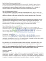 2
2
-
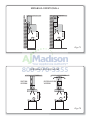 3
3
-
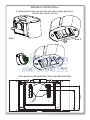 4
4
-
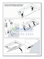 5
5
-
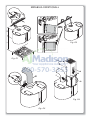 6
6
-
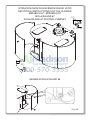 7
7
-
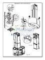 8
8
-
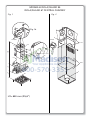 9
9
-
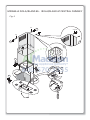 10
10
-
 11
11
-
 12
12
-
 13
13
-
 14
14
-
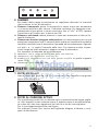 15
15
-
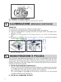 16
16
-
 17
17
-
 18
18
-
 19
19
-
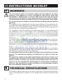 20
20
-
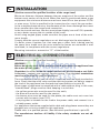 21
21
-
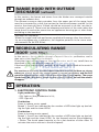 22
22
-
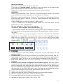 23
23
-
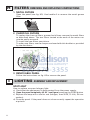 24
24
-
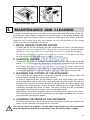 25
25
-
 26
26
-
 27
27
-
 28
28
-
 29
29
-
 30
30
-
 31
31
-
 32
32
-
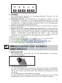 33
33
-
 34
34
-
 35
35
-
 36
36
-
 37
37
-
 38
38
-
 39
39
-
 40
40
-
 41
41
-
 42
42
-
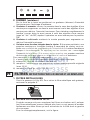 43
43
-
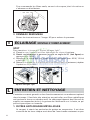 44
44
-
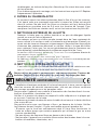 45
45
-
 46
46
-
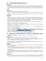 47
47
-
 48
48
-
 49
49
-
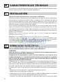 50
50
-
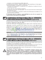 51
51
-
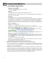 52
52
-
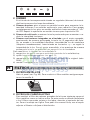 53
53
-
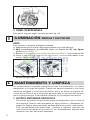 54
54
-
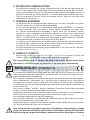 55
55
-
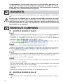 56
56
-
 57
57
-
 58
58
-
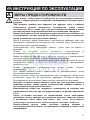 59
59
-
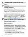 60
60
-
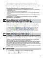 61
61
-
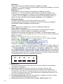 62
62
-
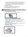 63
63
-
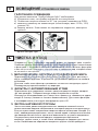 64
64
-
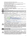 65
65
-
 66
66
-
 67
67
-
 68
68
-
 69
69
-
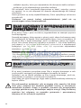 70
70
-
 71
71
-
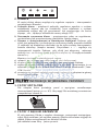 72
72
-
 73
73
-
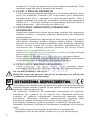 74
74
-
 75
75
-
 76
76
-
 77
77
-
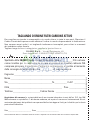 78
78
-
 79
79
-
 80
80


Falmec IS27MURNEWYORK El manual del propietario
- Categoría
- Campanas de cocina
- Tipo
- El manual del propietario
en otros idiomas
Artículos relacionados
-
Falmec lumen 60 El manual del propietario
-
Falmec Futura Export El manual del propietario
-
Falmec FPMEX30W6SS El manual del propietario
-
-
-
-
Falmec Imago Especificación
-
Falmec FDPST30I5SGW Instrucciones de operación
-
-
Falmec Quasar El manual del propietario
Otros documentos
-
 Futuro Futuro WL36MYSTIC-INOX Manual de usuario
-
Futuro Futuro WL36FLORARED El manual del propietario
-
Bertazzoni KIN30PROX Installation, Use and Care Manual
-
-
Futuro Futuro IS36POSITANO Guía de instalación
-
-
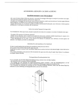 Futuro Futuro IS24AMALFI Guía de instalación
-
Futuro Futuro IS24LOMBARDY-WHT Guía de instalación
-
 Galvamet 395.586 Aria Exhausting Cooker Hood Manual de usuario
-
 Futuro Futuro IS24LOMBARDYBLK Guía de instalación


