
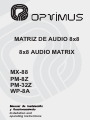
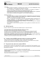
MATRIZ DE AUDIO 8x8
8x8 AUDIO MATRIX
MX-88
PM-8Z
PM-32Z
WP-8A
Installation and
operating instructions

MX-88 Versión 1.0 Página 1 de 18
MX-88
MATRIZ DE AUDIO 8x8
INDICE
1. INSTRUCCIONES DE SEGURIDAD ............................................................................. 2
2. ESPECIFICACIONES .................................................................................................... 3
3. MX-88 PANEL FRONTAL .............................................................................................. 4
4. MX-88 PANEL POSTERIOR .......................................................................................... 6
5. PM-8Z / PM-32Z PANEL FRONTAL .............................................................................. 8
6. PM-8Z / PM-32Z PANEL POSTERIOR .......................................................................... 9
7. CONTROL REMOTO DE PARED WP-8A ................................................................... 10
8. OPERACIONES ........................................................................................................... 11
8.1 Gestión de Prioridades ........................................................................................... 11
8.2 MX-88 Reproducción musical BGM ........................................................................ 11
8.3 MX-88 Reproducción desde el Micrófono de prioridad frontal ................................ 11
8.4 MX-88 Mensaje pregrabado interno ....................................................................... 11
8.5 WP-8A Conexión .................................................................................................... 12
8.6 Cambio de entrada BGM y ajuste del volumen de zona desde el WP-8A .............. 12
8.7 Reproducción de audio local usando el WP-8A ...................................................... 12
8.8 PM-8Z / PM-32Z Conexión ..................................................................................... 13
8.9 PM-8Z / PM-32Z Envío de mensajes de voz con prioridad .................................... 13
8.10 PM-8Z / PM-32Z Prioridades e indicación de ocupado ....................................... 13
8.11 PM-8Z / PM-32Z Edición de grupos .................................................................... 13
8.12 PM-8Z / PM-32Z Bloqueo de zonas .................................................................... 13
9. SISTEMA DE 4 MATRICES CONFIGURACIÓN ......................................................... 14
10. DIAGRAMA DE CONEXIONADO ................................................................................ 15
11. DIAGRAMA DE BLOQUES ......................................................................................... 16
12. ESPECIFICACIONES TÉCNICAS ............................................................................... 17
12.1 MX-88 .................................................................................................................. 17
12.2 PM-8Z / PM-32Z .................................................................................................. 17
12.3 WP-8A ................................................................................................................. 17
13. CERTIFICADO DE GARANTÍA ................................................................................... 18

MX-88 Versión 1.0 Página 2 de 18
MX-88
MATRIZ DE AUDIO 8x8
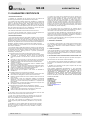
1. INSTRUCCIONES DE SEGURIDAD
La instalación de este sistema es muy simple. Recomendamos que se tome su tiempo en leerse
este manual a fin de asegurarse de realizar una instalación correcta.
Nunca instale este equipo en un ambiente con altas temperaturas, polvo, humedad o vibraciones ya
que podría alterar su rendimiento o reducir su vida útil.
Lea las instrucciones.
Guarde este manual.
Preste atención a todas las advertencias.
Siga las instrucciones.
No utilice este equipo cerca del agua.
Límpielo solamente con un paño seco.
No bloquee las aberturas de ventilación. Instálelo de acuerdo con las instrucciones del
fabricante.
No lo instale cerca de fuentes de calor tales como radiadores, calefactores, estufas u otros
aparatos (incluyendo amplificadores) que produzcan calor.
Evite que el cable de alimentación sea pisado o aplastado. Especialmente por la parte de
los enchufes.
Utilice sólo los accesorios especificados por el fabricante.
Desenchufe este equipo durante tormentas eléctricas o cuando no lo vaya a usar durante
largos periodos de tiempo.
Confíe todas las reparaciones a nuestro personal técnico cualificado. Se requiere servicio
técnico cuando el equipo ha sido dañado de alguna manera: el cable de alimentación o el
enchufe están dañados, se ha derramado líquido o han caído objetos dentro del equipo, el
equipo ha sido expuesto a la lluvia o a humedad, no funciona con normalidad o se ha caído.

MX-88 Versión 1.0 Página 3 de 18
MX-88
MATRIZ DE AUDIO 8x8
2. ESPECIFICACIONES
La MX-88 es una matriz de audio multicanal. Su objetivo es formar parte de un sistema de sonido
permanente en pubs, bares, restaurantes, hoteles, oficinas, fábricas, terminales, estaciones,
aeropuertos, etc., donde se utilizan múltiples fuentes de audio y deben combinarse fácilmente con
anuncios y avisos a una o más zonas. Es compatible con el micrófono PM-8Z / PM-32Z. Puede
contralarse, para cada una de las zonas de salida, el nivel de volumen y la fuente musical,
mediante el panel de control remoto WP-8A. Un cierre de contacto permite reproducir
automáticamente un mensaje pregrabado por el usuario o una entrada de alarma externa. El
altavoz monitor incorporado permite escuchar las 8 fuentes musicales de entrada.
8 entradas de música y 8 salidas con función de matriz completa.
4 micrófonos remotos.
Una entrada de micrófono de Prioridad con alimentación Phantom.
DRP (grabación y reproducción digital) hasta 55 s.
Extensión de salida para usar múltiples MX-88, hasta 4 unidades.
8 contactos para reproducir el mensaje pregrabado o la entrada externa a las zonas
deseadas.
Prioridad: Micrófono frontal (P) > Alarma (F) > PM-8Z / PM-32Z (A) >WP-8A (activo) (L) >
BGM
8 indicadores de entrada BGM (-20 dB).
Fácil instalación con cable CAT5.
Salidas balanceadas con controles de tono (100 Hz / 10 kHz).

MX-88 Versión 1.0 Página 4 de 18
MX-88
MATRIZ DE AUDIO 8x8
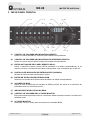
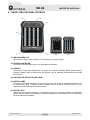
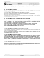
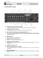
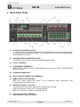
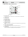
3. MX-88 PANEL FRONTAL
(1) CONTROL DE VOLUMEN DEL MICROFONO REMOTO
Ajusta el volumen del PM-8Z / PM-32Z para la salida correspondiente.
(2) CONTROL DE VOLUMEN DEL MICROFONO DE PRIORIDAD FRONTAL
Ajusta el volumen del micrófono frontal para la salida correspondiente.
(3) BOTON ACTIVACIÓN DEL PANEL REMOTO WP-8A.
Activa o desactiva el panel remoto WP-8A asociado a la salida correspondiente. Si se
activa el volumen y la selección de fuente musical pasan a ser controlados por el WP-8A.
(4) PANTALLA DE INDICACIÓN DE ENTRADA SELECCIONADA
Muestra la fuente musical seleccionada / activa.
(5) BOTÓN DE SELECCIÓN DE ENTRADA BGM
Selecciona la entrada de fuente musical asociada a la salida correspondiente.
(6) VOLUMEN DE BGM
Ajusta el nivel de salida de las entradas de BGM (música). No afecta ni al micrófono de
prioridad frontal ni el micrófono remoto.
(7) INDICADOR DE NIVEL DE SALIDA BGM
(8) CONTROL DE VOLUMEN DEL ALTAVOZ MONITOR
Este potenciómetro permite control el volumen de salida del altavoz monitor. No afecta a la
salida de audio.
(9) ALTAVOZ MONITOR
Altavoz de 5 W 4 Ω, usado para monitorizar las 8 entradas BGM.

MX-88 Versión 1.0 Página 5 de 18
MX-88
MATRIZ DE AUDIO 8x8
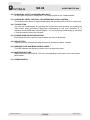
(10) ENTRADA DE MICRÓFONO DE PRIORIDAD Y GRABACIÓN
Entrada XLR para conectar el micrófono de prioridad. Se recomienda usar un micrófono
balanceado.
(11) CONTROL DE VOLUMEN DEL MICRO DE PRIORIDAD Y GRABACIÓN
Este potenciómetro permite ajustar el volumen de la entrada del micrófono de prioridad,
así como el volumen de grabación.
(12) BOTÓN TALK
Botón de activación del micrófono frontal. Puede iniciar la transmisión seleccionando la
zona deseada y presionando y manteniendo presionado esté botón. En este caso, el
carácter “P” se mostrará en la pantalla de indicación de entrada seleccionada. Puede
terminar la transmisión soltando el botón, y se liberarán también las zonas seleccionadas.
(13) BOTONES DE SELECCIÓN DE ZONAS
Pulse los botones para seleccionar las zonas donde se quiera enviar el mensaje.
(14) BOTÓN REC
Permite grabar un mensaje de audio para ser lanzado posteriormente desde los contactos
de alarma.
(15) INDICADOR LED BGM
El indicador se enciende al detectar señal en la entrada BGM correspondiente.
(16) INDICADOR LED MASTER/SLAVE
Muestra el modo de funcionamiento de la matriz MX-88. Se activa en función de la
configuración del sistema.
(17) INTERRUPTOR DE ALIMENTACIÓN

MX-88 Versión 1.0 Página 6 de 18
MX-88
MATRIZ DE AUDIO 8x8
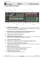
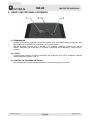
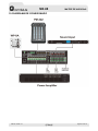
4. MX-88 PANEL POSTERIOR
(1) CONTACTOS DE ALARMA
El cierre de estos contactos hace que la unidad transmita el mensaje pregrabado interno, o
la señal de la entrada de alarma externa, por la salida correspondiente. La entrada se
selecciona desde el interruptor ALARM MESSAGE.
(2) INTERRUPTORES DE CONFIGURACIÓN LINK MODE [MASTER/SLAVE]
Interruptores de configuración para sistemas con varias MX-88.
(3) TERMINALES DE ALIMENTACIÓN DE 24 Vcc
(4) TERMINALES DE MUTE DEL SISTEMA
MUSIC MUTE silencia el audio de los canales de música BGM y de las entradas de los
mandos de pared. SYSTEM MUTE silencia todas las entradas.
(5) CONECTOR DE ALIMENTACIÓN CA
(6) TERMINALES DE CONEXIÓN PARA EL PUPITRE REMOTO PM-8Z / PM-32Z
(7) CONTROL DE VOLUMEN DE MICROFONO REMOTO
Cada potenciómetro ajusta el volumen del PM-8Z / PM-32Z conectado a la entrada de
micrófono remoto correspondiente.
(8) INTERFACE LINK IN / LINK OUT
Terminal para interconectar 4 matrices. Audio de prioridad y datos.
LINK IN: se conecta a LINK OUT de la MX-88 anterior.
LINK OUT: se conecta a LINK IN de la MX-88 siguiente.
(9) TERMINALES DE ENTRADA BGM
Terminales de entrada para las fuentes musicales.

MX-88 Versión 1.0 Página 7 de 18
MX-88
MATRIZ DE AUDIO 8x8
(10) TERMINALES BGM LINK IN/OUT
Terminales de entrada para las fuentes musicales con salida en paralelo.
(11) CONTROLES DE VOLUMEN DE LAS ENTRADAS BGM
(12) TERMINALES PAGING MIC LINK IN/OUT
Entrada para micrófono de prioridad. En paralelo con la entrada frontal. Sin phantom. Con
salida en paralelo.
(13) SELECTOR DE ENTRADA DE ALARMA
Selecciona el audio a reproducir cuando se activen los contactos de alarma, mensaje
pregrabado interno o entrada de alarma externa.
(14) ENTRADA DE ALARMA EXTERNA
(15) TERMINALES DE CONEXIÓN PARA CONTROLES REMOTOS WP-8A
Uno para cada salida. Desde el control remoto puede seleccionarse la fuente musical
asignada a la salida correspondiente y ajustar el volumen de la música.
(16) SALIDAS DE ZONA
Terminales de salida para zonas. Audio balanceado.
(17) CONTROLES DE TONO PARA SALIDAS DE ZONA
Ajuste de graves y agudos para las salidas de zona.

MX-88 Versión 1.0 Página 8 de 18
MX-88
MATRIZ DE AUDIO 8x8
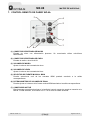
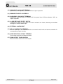
5. PM-8Z / PM-32Z PANEL FRONTAL
(1) INDICADORES LED
Alimentación (Azul), Señal (Verde), CLIP (Naranja), Ocupado (Rojo).
(2) ENTRADA DE MICRO
Conector de entrada para micro, con alimentación phantom.
(3) GRUPOS
Pulse estas teclas para seleccionar un grupo de zonas de llamada. Estas teclas también
pueden utilizarse para la edición de los grupos. Vea el apartado Operaciones para más
información.
(4) BOTONES DE SELECCIÓN DE ZONA
(5) BOTÓN CHIME
Pulse esta tecla para reproducir el gong de preaviso. Las zonas no se deseleccionarán tras
la emisión del gong. También puede utilizarse esta tecla para bloquear zonas. Vea el
apartado Operaciones para más información.
(6) BOTÓN TALK
Seleccione las zonas de emisión y a continuación pulse y mantenga pulsado el botón para
hablar. Suelte el botón para finalizar. Durante la transmisión, se muestra "R" en las pantallas
de las zonas seleccionadas.

MX-88 Versión 1.0 Página 9 de 18
MX-88
MATRIZ DE AUDIO 8x8
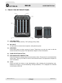
6. PM-8Z / PM-32Z PANEL POSTERIOR
(1) TERMINACIÓN
Cuando se conectan múltiples pupitres al sistema, este conmutador debe ponerse en ON,
para finalizar el bus RS485 en el primeo y en el último pupitre.
(En un sistema máximo con 4 MX-88 y 16 pupitres, deberían ponerse en ON el
PM-8Z / PM-32Z(1) de la MX-88(1) y el PM-8Z / PM-32Z(4) de la MX-88(4), y dejar en OFF
el resto).
(2) C-PORT
Terminal para conectar el cable proveniente de la MX-88. UTP CAT5. Distancia máxima
desde la MX-88 al pupitre, 300 m.
(3) CONTROL DE VOLUMEN DE SALIDA
Este potenciómetro ajusta simultáneamente el volumen del gong y del micro.

MX-88 Versión 1.0 Página 10 de 18
MX-88
MATRIZ DE AUDIO 8x8
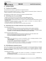
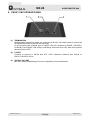
7. CONTROL REMOTO DE PARED WP-8A
(1) CONECTOR DE ENTRADA DE MICRO
Entrada de micro con alimentación phantom. Se recomienda utilizar micrófonos
balanceados.
(2) CONECTOR DE ENTRADA DE LÍNEA
Entrada de audio a nivel de AUX.
(3) VOLUMEN DE MICRO
Ajusta el volumen de la entrada de micro.
(4) VOLUMEN DE LÍNEA
Ajusta el volumen de la entrada de línea.
(5) SELECTOR DE FUENTE MUSICAL BGM
Permite seleccionar cuál de las entradas BGM quedará asociada a la salida
correspondiente.
(6) POTENCIOMETRO DE VOLUMEN DE ZONA
Permite ajustar el volumen de la fuente musical BGM asociada a la salida correspondiente.
(7) COMUTADOR ACTIVE
Este interruptor permite seleccionar si el audio del control remoto de pared se transmite a la
MX-88. Si está activado, se muestra una "L" en la zona de salida asociada.

MX-88 Versión 1.0 Página 11 de 18
MX-88
MATRIZ DE AUDIO 8x8
8. OPERACIONES
8.1 Gestión de Prioridades
Las prioridades del sistema se gestionan de la siguiente manera:
Micrófono de prioridad del panel frontal (P) > Señal de alarma de evacuación (interna / externa) (F)
> PM-8Z / PM-32Z (A) > WP-8A (activado) (L) > BGM
Las señales de prioridad superior silencian las señales de prioridad inferior.
8.2 MX-88 Reproducción musical BGM
- Conecte una fuente musical a los terminales de entrada BGM posteriores.
- El LED frontal asociado a la entrada se enciende cuando se detecta la señal.
- El altavoz monitor frontal puede reproducir el audio de cada entrada BGM seleccionando el canal
correspondiente.
- Seleccione la entrada asociada a cada salida usando los botones de selección BGM, a
continuación ajuste los volúmenes de salida.
- La pantalla asociada a cada salida mostrará la entrada seleccionada.
8.3 MX-88 Reproducción desde el Micrófono de prioridad frontal
- Conexión del micrófono.
o Conecte un micrófono al terminal de entrada micrófono frontal y ajuste el volumen.
o Si se utiliza un micrófono de condensador, debe utilizarse un conector balanceado.
o Si se usa un micrófono dinámico desbalanceado, el nivel de sonido y la calidad pueden
degradarse. Se recomienda utilizar un micrófono dinámico balanceado.
- Selección de las zonas de avisos.
o Pulse las teclas de zona del panel frontal para seleccionar las zonas donde emitir.
o Pulse la tecla PAGING ALL para seleccionar todas las zonas.
o Las zonas activadas se encenderán en color azul.
- Transmisión.
o Después de seleccionar las zonas de transmisión, pulse y mantenga pulsado el botón
TALK para hablar.
o “P” se mostrará en la pantalla de las zonas seleccionadas.
o Suelte el botón TALK para finalizar la transmisión.
o El botón de selección de zona se apagará y las pantallas de indicación de entrada
asociada volverán al estado anterior de visualización de BGM.
8.4 MX-88 Mensaje pregrabado interno
Como esta unidad tiene un IC de grabación digital incorporado, el usuario puede grabar un mensaje
de voz. La grabación puede durar hasta 55 segundos y los contenidos grabados pueden
transmitirse a las zonas seleccionadas mediante los terminales de alarma ubicados en la parte
posterior de la unidad.
- Conexión del micrófono.
o Ajuste el volumen después de conectar un micrófono a la entrada de micrófono de
prioridad del panel frontal
o El micrófono es el mismo que se utilizaría para emitir avisos de prioridad.

MX-88 Versión 1.0 Página 12 de 18
MX-88
MATRIZ DE AUDIO 8x8
- Grabación
o Pulse el botón de grabación 2 segundos para ingresar en el modo GRABACIÓN. Podrá
ver "-RECORD-" en las pantallas de indicación de entrada.
o Pulse nuevamente 2 segundos para iniciar la grabación, se mostrara el indicador “-”
rotando en las pantallas de indicación de entrada seleccionada 1 y 8.
o Pulse brevemente el botón de grabación para salir del modo GRABACIÓN, las pantallas
de indicación de entrada volverán a mostrar la entrada BGM anterior.
o Para cambiar el contenido de la grabación, vuelva a realizar la grabación.
- Mensaje de alarma
o Si se cierra GND con el número de PIN equivalente a cada salida de zona del terminal de
contactos de alarma ubicado la parte posterior de la unidad, se transmitirá el mensaje
grabado o una señal de audio externa a esa zona.
o Una “F” se mostrará en las pantallas de indicación de entrada durante la reproducción. El
mensaje pregrabado o la señal externa se reproducen indefinidamente mientras el
contacto está cerrado, y la reproducción finaliza si se libera el contacto.
o Si se utilizan varias MX-88 como sistema enlazado, se recomienda grabar los mensajes
individualmente en cada MX-88.
o Si el contacto se activa durante la grabación, solo se graban los contenidos antes de la
activación.
8.5 WP-8A Conexión
Conecte el WP-8A a la parte trasera de la MX-88 usando un cable UTP CAT5.
- La longitud máxima del cable desde la MX-88 al WP-8 es de 300 m.
- Se permite conectar hasta 8 mandos WP-8A a una MX-88.
- El equipo reconoce automáticamente el WP-8A sin necesidad de una configuración de ID.
- Puede seleccionar fuentes BGM o ajustar el volumen de salida BGM utilizando un WP-8A.
- Puede activar o desactivar el control del WP-8A con el botón WALL CTRL en la parte frontal de la
MX-88. Si el control WP-8A está activado, el botón de la MX-88 se ilumina.
- Gire el potenciómetro de volumen en el sentido de las agujas del reloj hasta que el volumen sea
suficiente, ya que este se ajusta al mínimo para el uso inicial.
8.6 Cambio de entrada BGM y ajuste del volumen de zona desde el WP-8A
- Active el WP-8A pulsando la tecla WALL CTRL en el panel frontal de la MX-88.
- Verifique que el número de entrada BGM cambia al manipular el control SELECT de la unidad.
- Ajuste el nivel de audio local usando el potenciómetro de volumen.
8.7 Reproducción de audio local usando el WP-8A
La reproducción de audio local independiente es posible si se usa WP-8A. Puede reproducir, en su
zona respectiva, audio de un micrófono o de una fuente musical distinta de las señales conectadas
directamente a la MX-88.
- Conecte una fuente de sonido o un micrófono a la entrada LINE o MIC.
-
Pulse el la tecla ACTIVE, una L se mostrará en la pantalla indicadora de entrada seleccionada
correspondiente.
- Ajuste el volumen utilizando el control de volumen correspondiente.
- Se permite la transmisión inmediata.

MX-88 Versión 1.0 Página 13 de 18
MX-88
MATRIZ DE AUDIO 8x8
- El volumen de salida local se ajusta utilizando el volumen del potenciómetro WP-8A o el volumen
del potenciómetro MX-88 según estado del botón Wall control.
8.8 PM-8Z / PM-32Z Conexión
- Conecte el pupitre a la parte trasera de la MX-88 con un cable UTP CAT5. El mismo método de
conexión que para el WP-8A.
- La longitud máxima del cable desde la MX-88 al pupitre es de 300 m.
- Se permite la transmisión inmediata, no requiere una configuración ID por separado.
- Se pueden conectar 4 pupitres por MX-88.
- El parpadeo de los botones significa un fallo en la unidad o en la conexión, por lo tanto, verifique
el estado de la conexión y la unidad.
8.9 PM-8Z / PM-32Z Envío de mensajes de voz con prioridad
- Conecte un micrófono a la toma de entrada de micrófono del pupitre. Se pueden usar tanto
micrófonos dinámicos como de condensador.
- Pulse el botón de la zona donde quiera enviar el mensaje, el botón se encenderá. Todas las
zonas de la MX-88 se seleccionarán al pulsar el botón ALL.
- Una R se mostrará en las pantallas de indicación de entrada de las salidas seleccionadas.
- Pulse el botón CHIME, el pupitre enviará la señal de gong a las zonas seleccionadas.
- Pulse y mantenga pulsado el botón TALK para hablar.
- Suelte el botón para finalizar la emisión.
8.10 PM-8Z / PM-32Z Prioridades e indicación de ocupado
- Los pupitres PM-8Z / PM-32Z puede enviar avisos a cualquier zona que no esté ocupada por una
señal de prioridad igual o superior.
- Si algún botón de zona está activado, juntamente con el LED BUSY, indica que dicha zona está
actualmente ocupada por otro pupitre.
8.11 PM-8Z / PM-32Z Edición de grupos
El equipo permite crear grupos de zonas. Para asignar zonas a un grupo pulse durante 2 segundos
la tecla del grupo a editar, esta parpadeará indicando que el sistema ha entrada en modo edición, y
seleccione las zonas deseadas. Pulse nuevamente la tecla del grupo durante 2 segundos para
finalizar y guardar la configuración en memoria. Si se pulsa menos de 2 segundos la configuración
solo se guardará temporalmente y se perderá al reiniciar el equipo.
8.12 PM-8Z / PM-32Z Bloqueo de zonas
Seleccione las zonas y pulse la tecla CHIME durante 2 segundos para bloquearlas. A partir de ese
momento no se podrá seleccionar o deseleccionar ninguna otra tecla de zona. Pulse nuevamente 2
segundos o reinicie el equipo para liberar las zonas.

MX-88 Versión 1.0 Página 14 de 18
MX-88
MATRIZ DE AUDIO 8x8
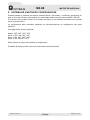
9. SISTEMA DE 4 MATRICES CONFIGURACIÓN
Puede montarse un sistema con hasta 4 matrices MX-88, una master y 3 esclavas, permitiendo un
total de 32 zonas. Dichas zonas podrán ser controladas desde cualquier pupitre PM-8Z / PM-32Z.
El micrófono de prioridad frontal, los mensajes de alarma y las entradas musicales solo actuarán
sobre su propia matriz.
La configuración debe realizarse mediante los microinterruptores de configuración del panel
posterior.
La configuración sería la siguiente:
Master: OFF, OFF, OFF, OFF
Slave 1: OFF, ON, OFF, OFF
Slave 2: ON, OFF, OFF, OFF
Slave 3: ON, ON; OFF, OFF
Debe reiniciar el equipo tras cambiar la configuración.
El estado del equipo puede verse en los indicadores del panel frontal.

MX-88 Versión 1.0 Página 15 de 18
MX-88
MATRIZ DE AUDIO 8x8
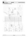
10. DIAGRAMA DE CONEXIONADO

MX-88 Versión 1.0 Página 16 de 18
MX-88
MATRIZ DE AUDIO 8x8
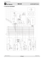
11. DIAGRAMA DE BLOQUES

MX-88 Versión 1.0 Página 17 de 18
MX-88
MATRIZ DE AUDIO 8x8
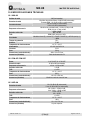
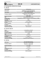
12. ESPECIFICACIONES TÉCNICAS
12.1 MX-88
Salidas de audio 0 dB (balanceadas)
Entradas de audio
Micrófono de prioridad frontal -50 dB ±3 dB (balanceado)
Entradas BGM 1~8 -20 dB ±3 dB (no balanceadas)
Controles de tono
100 Hz ±12 dB (no balanceadas)
10 kHz ±12 dB (no balaceadas)
Respuesta en frecuencia
Micrófono de prioridad frontal ( 100 Hz~10 kHz) ±3 dB
BGM ( 60 Hz ~15 kHz) ±3 dB
Relación señal ruido
BGM > 80 dB
MIC > 65 dB
THD BGM y MIC, inferior al 0,05%
Prioridades
Micrófono frontal (P) > Alarma (F) > PM-8Z / PM-32Z (A) > WP-8A (activo) (L)
> BGM
Tiempo de grabación 55 s
Diafonía 75 dB
Temperatura de funcionamiento -10º C ~ +40 ºC
Alimentación 100~240 Vca 50/60 Hz
Consumo 35 W
Peso 5,8 kg
Dimensiones (ancho/alto/fondo) 482 x 132 x 315 mm
Accesorios (incluidos) Cable de alimentación CA
12.2 PM-8Z / PM-32Z
Zonas 8 PM-8Z, 32 PM-32Z
Entrada de audio -50 dB ±3 dB (balanceada)
Respuesta en frecuencia 100 Hz ~10 kHz ± 3dB
Relación señal ruido > 65 dB
THD < 0,05%
Temperatura de funcionamiento -10º C ~ +40 ºC
Peso 930 g
Dimensiones (ancho/alto/fondo) 140 x 55 x 204 mm
Accesorios (incluidos) Micrófono cuello de cisne 430 mm
12.3 WP-8A
Entradas de audio
Mic -50 dB ±3 dB (balanceada)
Línea -20 dB ±3 dB (no balanceada)
Respuesta en frecuencia
Mic (100Hz ~ 10kHz) ±3 dB
Línea (60Hz ~ 15kHz) ±3 dB
Relación señal ruido
Línea > 80 dB
Mic > 65 dB
THD < 0.05%
Temperatura de funcionamiento -10º C ~ +40 ºC
Peso 180 g
Dimensiones (ancho/alto/fondo) 110 x 110 x 40 mm
Accesorios (incluidos) Caja de empotrar

MX-88 Versión 1.0 Página 18 de 18
MX-88
MATRIZ DE AUDIO 8x8
13. CERTIFICADO DE GARANTÍA
1. La empresa OPTIMUS S.A. garantiza que sus productos se encuentran libres
de defectos en materiales y de mano de obra en el momento de su entrega
original al comprador.
2. La empresa OPTIMUS S.A. concede a sus productos, conforme a las
condiciones aquí descritas, una garantía de dos (2) años a partir de la fecha de
adquisición del producto por el comprador. Si, dentro de este plazo de garantía, se
producen defectos que no sean debidos a razones mencionadas bajo el punto 2,
la empresa OPTIMUS S.A. remplazará o reparará el aparato utilizando piezas de
recambio equivalentes, nuevas o reconstruidas, según criterio propio. Si se
aplican piezas de recambio que constituyen una mejora del aparato, la empresa
OPTIMUS S.A. se reserva el derecho de cargar el coste adicional de estos
componentes al cliente.
3. No se concederán prestaciones de garantía distintas a las citadas.
4. Para la utilización de los derechos de garantía será requisito indispensable
presentar la factura de compra original o el certificado de garantía.
2. DISPOSICIONES DE GARANTÍA
1. Si el producto tuviera que ser modificado o adaptado para cumplir con los
requisitos locales en cuanto a técnica o seguridad, si no se trata del país para el
cual el producto fue concebido y fabricado originalmente, ello no se considera
como defecto de material o de fabricación. Por lo demás, la garantía no
comprende la realización de estas modificaciones o adaptaciones,
independientemente de si éstas hayan sido ejecutadas debidamente o no.
OPTIMUS S.A. tampoco asumirá costes en el marco de la garantía por este tipo
de modificaciones.
2. La garantía no dará derecho a inspección o mantenimiento gratuito o
reparación del aparato, particularmente si los defectos son debidos a uso
inapropiado. Los derechos de garantía tampoco abarcan defectos en piezas de
desgaste que sean debidos a un desgaste normal. Piezas de desgaste son, en
particular, potenciómetros, interruptores/teclas, y piezas similares.
3. La garantía no abarca los defectos en el equipo causados por:
Abuso o uso incorrecto del aparato para fines distintos a los previstos, en
incumplimiento de las instrucciones de servicio y de mantenimiento
especificadas en el Manual y/o Instrucciones Técnicas del equipo.
Conexión o uso del producto de una manera que no corresponda a los
requisitos técnicos o de seguridad del país en el cual se utiliza el aparato.
Instalación en condiciones distintas a los indicados en el Manual y/o
Instrucciones Técnicas.
Deficiencia o interrupciones tensión eléctrica o defectos de instalación que
impliquen uso en condiciones anormales.
Daños ocasionados por otros equipos interconectados al producto.
El uso o instalación de Software (programas), interfaces, partes o
suministros no proporcionados y/o autorizados por OPTIMUS S.A.
La no utilización de los embalajes originales para su transporte.
Daños causados por fuerza mayor u otras causas no imputables a
OPTIMUS S.A.
4. No están cubiertos por esta garantía los siguientes elementos:
Todas las superficies de plástico y todas las piezas expuestas al exterior
que hayan sido rayadas o dañadas debido al uso normal o anormal.
Las roturas, golpes, daños por caídas o ralladuras causadas por traslados
de cualquier naturaleza.
Defectos de daños derivados de pruebas, uso, mantenimiento, instalación y
ajustes inapropiados, o derivados de cualquier alteración o modificación de
cualquier tipo no realizada por en Servicio Autorizado por OPTIMUS S.A. en
cumplimiento de esta garantía.
Los daños personales o a la propiedad que pudieran causar el uso indebido
del equipo, incluyendo la falta de mantenimiento.
5. La garantía carecerá de validez cuando se observe:
Enmiendas o tachaduras en los datos del certificado de garantía o factura
de compra.
Falta de factura original o falta de fecha en la misma.
Falta de número de serie o lote en el equipo.
6. La garantía no cubre los desplazamientos por asistencias técnicas a excepción
de los motivados por incidencias ocurridas durante los tres primeros meses.
7. En el caso de ordenadores PC, la garantía no cubrirá la eliminación de virus
informáticos, restauración de programas por este motivo o la reinstalación del
disco provocada por el borrado del mismo.
8. Los derechos de garantía se anulan si el producto ha sido reparado o abierto
por un personal no autorizado OPTIMUS S.A. o por el propio cliente.
9. Si la empresa OPTIMUS S.A. estableciera al comprador del aparato que los
daños presentados no dan derecho a la reclamación de la garantía, los costes de
las prestaciones de revisión por parte de la empresa OPTIMUS S.A. correrán a
cargo del cliente.
10. Los productos sin derechos de garantía sólo se repararán contra pago de los
gastos por el cliente. En caso de ausencia de derechos de garantía, OPTIMUS
S.A. informará al cliente al respecto. Si, en un plazo de 6 semanas a partir de esta
comunicación, no recibimos ninguna orden de reparación escrita confirmando la
aceptación de los gastos, OPTIMUS S.A. devolverá el aparato en cuestión al
cliente. En este caso, los gastos de transporte y embalaje se facturarán por
separado y se cobrarán contra reembolso. En caso de expedición de una orden
de reparación, confirmando la asunción de los gastos, los gastos de transporte y
de embalaje se facturarán adicionalmente, igualmente por separado.
11. En caso de necesidad de traslado al Centro de Servicio Autorizado, el
transporte será realizado por el responsable de la garantía, y serán a su cargo los
gastos de flete y seguro.
12. En caso de falla, OPTIMUS S.A. asegura al comprador la reparación y/o
reposición de partes para su correcto funcionamiento en un plazo no mayor a 30
días. No obstante, se deja aclarado que el plazo usual no supera los 30 días.
13. Todas las piezas o productos sustituidos al amparo de los servicios en
garantía pasarán a ser propiedad de OPTIMUS S.A.
3. TRANSFERENCIA DE LA GARANTÍA
La garantía se concede únicamente para el comprador original (cliente principal) y
es intransferible. Con excepción de la empresa OPTIMUS S.A., ningún tercero
(comerciantes, etc.) está autorizado a conceder garantía adicionales en nombre
de la empresa OPTIMUS S.A.
4. RECLAMACIONES POR DAÑOS Y PERJUICIOS
En caso de que OPTIMUS S.A. no pueda proporcionar un servicio de garantía
adecuado, el comprador no tendrá ningún derecho a reclamar indemnización
alguna por daños y perjuicios consecuentes. La responsabilidad de la empresa
OPTIMUS S.A. se limita en todo caso al precio de facturación del producto
5. RELACIÓN CON OTROS DERECHOS DE GARANTÍA Y CON EL DERECHO
NACIONAL
1. Mediante esta garantía no se afecta a los derechos del comprador frente al
vendedor deducidos del contrato de compraventa concluido.
2. Las presentes condiciones de garantía de la empresa OPTIMUS S.A. son
válidas siempre que no contradigan el derecho nacional correspondiente en
relación con las disposiciones de garantía.
3. OPTIMUS S.A. asegura que este producto cumple con las normas de seguridad
vigentes en el país.
ESTA DECLARACIÓN DE GARANTÍA LIMITADA ES LA GARANTÍA EXCLUSIVA
OFRECIDA POR OPTIMUS S.A. SE EXCLUYE TODA OTRA GARANTÍA
EXPLÍCITA O IMPLÍCITA, INCLUIDAS LAS GARANTÍAS DE COMERCIALIDAD
Y APTITUD A UN FIN DETERMINADO. (EXCEPTO CUANDO DICHAS
GARANTÍAS SEAN REQUERIDAS POR UNA LEY APLICABLE). NINGUNA
GARANTÍA, YA SEA EXPLÍCITA O IMPLÍCITA, SE APLICARÁ TRAS LA
FINALIZACIÓN DEL PERIODO DE GARANTÍA.
OPTIMUS S.A.
Servicio Post Venta
C/ Barcelona 101
17003 - GIRONA
Tel. 902 151 96 / 972 203 300
Fax. 972 21 84 13
e-mail : [email protected]
1999/44/CE

MX-88 Version 1.0 Page 1 of 18
MX-88
AUDIO MATRIX 8x8
INDEX
1. SECURITY INSTRUCTIONS ......................................................................................... 2
2. SPECIFICATIONS ......................................................................................................... 3
3. MX-88 FRONT PANEL .................................................................................................. 4
4. MX-88 REAR PANEL ..................................................................................................... 6
5. PM-8Z / PM-32Z FRONT PANEL .................................................................................. 8
6. PM-8Z / PM-32Z REAR PANEL ..................................................................................... 9
7. REMOTE WALL PANEL CONTROL WP-8A .............................................................. 10
8. OPERATIONS .............................................................................................................. 11
8.1 Priority management .............................................................................................. 11
8.2 MX-88 BGM Broadcasting ...................................................................................... 11
8.3 MX-88 Paging frontal MIC Broadcasting ................................................................ 11
8.4 MX-88 Built-in IC Recording and Play .................................................................... 11
8.5 WP-8A Connection ................................................................................................. 12
8.6 Changing of BGM input and volume adjustment in output zone using WP-8A ....... 12
8.7 Independent Local BGM and MIC Broadcasting using WP-8A ............................... 12
8.8 PM-8Z / PM-32Z Connection .................................................................................. 13
8.9 PM-8Z / PM-32Z MIC Broadcasting ........................................................................ 13
8.10 PM-8Z / PM-32Z Priority and busy ...................................................................... 13
8.11 PM-8Z / PM-32Z Groups of zones....................................................................... 13
8.12 PM-8Z / PM-32Z Zone lock ................................................................................. 13
9. 4 MATRIX SYSTEM CONFIGURATION ...................................................................... 14
10. CONNECTION DIAGRAM ........................................................................................... 15
11. BLOCK DIAGRAM....................................................................................................... 16
12. TECHNICAL SPECIFICATIONS .................................................................................. 17
12.1 MX-88 .................................................................................................................. 17
12.2 PM-8Z / PM-32Z .................................................................................................. 17
12.3 WP-8A ................................................................................................................. 17
13. GUARANTEE CERTIFICATE ...................................................................................... 18

MX-88 Version 1.0 Page 2 of 18
MX-88
AUDIO MATRIX 8x8
1. SECURITY INSTRUCTIONS
The installation of this system is very simple. But we advise you to take your time to read this
manual to ensure accurate installation to perform.
Never place this equipment in an environment that could affect their performance or reduce its life.
Such environment includes the high temperatures, dust, humidity and vibration.
Read these instructions.
Keep this manual.
Heed all warnings.
Follow all instructions.
Do not use this apparatus near water.
Clean only with dry cloth.
Do not block the ventilation openings. Install it in accordance with the manufacturer’s
instructions.
Do not install near any heat sources such as radiators, heaters, stoves or other apparatus
(including amplifiers) that produce heat.
Protect the power cord from being walked on or pinched, especially the plugs.
Use only accessories specified by the manufacturer.
Unplug this apparatus during lightning storms or when you do not use it for a long period of
time.
Refer all servicing to qualified staff. Servicing is required when the equipment has been
damaged in any way: the power cord or plug is damaged, liquid has been spilled or objects
have fallen into the apparatus, the equipment has been exposed to rain or moisture, does
not work normally or has been dropped.

MX-88 Version 1.0 Page 3 of 18
MX-88
AUDIO MATRIX 8x8
2. SPECIFICATIONS
The MX-88 is multi zone audio matrix system. It is intended to form part of permanent sound system
in pubs, bars, restaurants, hotels, offices, factories, terminals, stations, airports etc., where multiple
audio sources are in use and need to be easily combined with announcements and/or paging to one
or more zones. It is compatible with PM-8Z / PM-32Z paging microphones. Each of output zones
can be controlled, volume level and music source, by remote control panel WP-8A. A contact
closure allows playing user recordable message or external alarm input automatically. A built in
monitor speaker allows to listen to the 8 input music sources.
8 Music input and 8 outputs with full matrix.
4 remote microphone stations.
A Paging microphone input with Phantom.
DRP (Digital recording and playback) up to 55 sec.
Output extension for using multiple MX-88, up to 4 units.
8 contact for broadcasting prerecorded message or external input to desired zones.
Priority: Paging MIC (P) > Alarm (F) > PM-8Z / PM-32Z (A) > WP-8A (active) (L) > BGM
8 BGM input indicators (-20 dB).
Easy installation with CAT5 cable.
Balanced outputs with tone controls (100 Hz / 10 kHz).

MX-88 Version 1.0 Page 4 of 18
MX-88
AUDIO MATRIX 8x8
3. MX-88 FRONT PANEL
(1) REMOTE MIC STATION LEVEL CONTROL
This adjusts the signal level PM-8Z / PM-32Z remote microphone for each channel.
(2) PAGING MIC LEVEL CONTROL
This adjusts the signal level of the paging microphone for each channel.
(3) WALL MOUNT CONTROLLER (WP-8A) ENABLE BUTTON
This is a toggle switch to select whether the Wall Controller (WP-8A) connected to each
output zone is enable/disable. If the button turns on, BGM source and volume are
controlled by WP-8A.
(4) INPUT DISPLAY
Displays selected / active BGM source.
(5) BGM INPUT SELECTION BUTTON
BGM sources can be selected by these button.
(6) BGM OUTPUT LEVEL CONTROL
This adjusts BGM output level. It does not affect neither paging microphone nor remote
microphone.
(7) BGM OUTPUT LEVEL LED
(8) MONITOR SPEAKER LEVEL CONTROL
This potentiometer allows to adjust Monitor Speaker output level. It has no effect over
audio output.
(9) MONITOR SPEAKER
Built-in 5-Watt Power Amplifier and 4 Ω Monitor Speaker to monitor selected one of 8 BGM
sources.

MX-88 Version 1.0 Page 5 of 18
MX-88
AUDIO MATRIX 8x8
(10) PAGING MIC INPUT / RECORDING MIC INPUT
An input jack to connect a Paging MIC. It is recommended to use a balanced MIC.
(11) PAGING MIC LEVEL CONTROL / RECORDING MIC LEVEL CONTROL
This potentiometer allows to adjust broadcasting and recording built-in DRP IC output level.
(12) TALK BUTTON
You can start broadcasting by selecting the desired area and pressing and holding the
TALK button when performing Paging MIC broadcasting. In this case, character “P” is
displayed on the BGM input channel display. You can terminate broadcasting by releasing
it, and the selected zones are released.
(13) PAGING ZONE SELECTION BUTTON
Press these buttons to select the zones where you want to broadcast.
(14) REC BUTTON
It allows to record an audio message that can be activated by alarm contacts.
(15) BGM INPUT LED AND BGM SOURCE LABEL
This LED indicates that signal is present in the corresponding input.
(16) MASTER/SLAVE LED
Displays mode in link of MX-88. This turns on depending on the status of the rear System
Mode switch.
(17) POWER SWITCH

MX-88 Version 1.0 Page 6 of 18
MX-88
AUDIO MATRIX 8x8
4. MX-88 REAR PANEL
(1) EVACUATION ALARM CONTACT
The closure of these contacts makes the unit to broadcast the internal recorded message,
or external Alarm message input signal, to the corresponding output. Input is selected from
ALARM MESSAGE switch.
(2) LINK MODE SWITCH [MASTER/SLAVE]
This switch is used to set the link mode for MX-88 linked system.
(3) DC 24 V TERMINAL
(4) SYSTEM MUTE TERMINALS
MUSIC MUTE silences audio of BGM channels and wall panel inputs. SYSTEM MUTE
silences all inputs.
(5) AC MAINS POWER INLET
(6) PM-8Z / PM-32Z CONNECTION TERMINALS
(7) REMOTE MIC LEVEL CONTROL
Each level control adjusts the volume of the microphone desk connected to the
corresponding Remote Mic input.
(8) INTERFACE LINK IN / LINK OUT
Terminals used to link up to 4 audio matrix. Paging audio and data.
LINK IN: Connects to LINK OUT of the upper MX-88.
LINK OUT: Connects to LINK IN of the lower MX-88.
(9) BGM SOURCE INPUT TERMINAL
Input terminals to input BGM sources.

MX-88 Version 1.0 Page 7 of 18
MX-88
AUDIO MATRIX 8x8
(10) BGM INPUT LINK IN/OUT TERMINAL
Input terminals to input BGM sources, with an output in parallel.
(11) BGM INPUTS LEVEL CONTROLS
(12) PAGING MIC LINK IN/OUT TERMINAL
Paging MIC input terminals. In parallel with front panel input. Without phantom. With an
output in parallel.
(13) ALARM MESSAGE SELECT SWITCH
It selects the audio to play when the alarm contacts are closed, internal pre-recorded
message or external alarm input.
(14) EXTERNAL ALARM INPUT
(15) WP-8A CONNECTION TERMINAL
One for each input. The remote controls can control music level and source selection for
corresponding output remotely.
(16) ZONE INDIVIDUAL OUTPUT TERMINAL
Zone output terminals for Balanced Audio.
(17) ZONE OUTPUT TONE CONTROL
Bass and treble controls for zone outputs.

MX-88 Version 1.0 Page 8 of 18
MX-88
AUDIO MATRIX 8x8
5. PM-8Z / PM-32Z FRONT PANEL
(1) LED INDICATOR
Power (Blue), Signal (Green), CLIP (Orange), Busy (Red).
(2) MIC INPUT
An input jack to connect the microphone, with phantom power.
(3) GROUPING
Press these keys to select a group of zones. These keys can also be used to edit the
zones included in the groups. See Operations chapter for more information.
(4) ZONE SELECTION BUTTON
(5) PRE-ANNOUNCE CHIME BUTTON
Press this button for playing the pre-announcement chime. Zones won’t be unselected after
chime ends. This key can also be used to lock selected zones. See Operations chapter for
more information.
(6) TALK
Press and hold the button to start broadcasting, after selecting the broadcasting zone.
Release the button to end broadcasting. During broadcast, “R” is displayed for selected
zones display of MX-88.

MX-88 Version 1.0 Page 9 of 18
MX-88
AUDIO MATRIX 8x8
6. PM-8Z / PM-32Z REAR PANEL
(1) TERMINATION
When multiple microphone desks are connected to MX-88, this switch needs to turned ON
for RS485 termination in the first and last ones.
(In a full system with 4 MX-88 and 16 PM-8Z / PM-32Z, switches for PM-8Z / PM-32Z(1)
of MX-88(1) and PM-8Z / PM-32Z(4) of MX-88(4) should be set to ON, while all the others
should be set to OFF)
(2) C-PORT
Terminal to connect to MX-88 with UTP CAT5. Maximum distance from MX-88 to
PM-8Z / PM-32Z is 300 m.
(3) OUTPUT VOLUME
MIC and Chime broadcasting level can be adjusted by this potentiometer.

MX-88 Version 1.0 Page 10 of 18
MX-88
AUDIO MATRIX 8x8
7. REMOTE WALL PANEL CONTROL WP-8A
(1) MIC INPUT JACK
An input jack to connect a Condenser MIC. It is recommended to use a balanced MIC.
(2) LINE INPUT JACK
Line input terminal.
(3) MIC INPUT VOLUME
Adjusts MIC input volume.
(4) LINE INPUT VOLUME
Adjusts Line input volume.
(5) BGM SELECT SWITCH
It permits to select which of the BGM inputs will be broadcasted by the associated output
zone.
(6) ZONE VOLUME POTENTIOMETER
It permits to adjust BGM output volume of the associated output zone.
(7) ACTIVE SWITCH
This switch permits to select whether the audio of the wall panel is broadcasted to the
MX-88. If it activated an “L” is displayed in the associated output zone.

MX-88 Version 1.0 Page 11 of 18
MX-88
AUDIO MATRIX 8x8
8. OPERATIONS
8.1 Priority management
This system broadcasts according to following priority:
Front panel Paging Mic (P) > Evacuation alarm signal (internal / external) (F) > PM-8Z / PM-32Z (A)
> WP-8A (active) (L) > BGM
Higher priority signals mute lower priority signals.
8.2 MX-88 BGM Broadcasting
- Connect a BGM source unit to the rear BGM input terminals.
- The front LED associated to the input turns on when signal is detected.
- Audio can be heard by the front monitor speaker by selecting the input channel.
- Select the Input for each output by using the BGM selection buttons and then adjust the outputs
volume.
- BGM input display will show selected audio input.
8.3 MX-88 Paging frontal MIC Broadcasting
- MIC Connection
o Connect a microphone to the front MIC input terminal and adjust volume.
o If using a condenser MIC, MIC input must be applied with a balanced plug.
o If using an unbalanced dynamic MIC, sound level and quality can be degraded. It is
recommended to use balanced dynamic MIC.
- Selection of Broadcasting Zone.
o Press the Paging Zone Selection buttons for the zones to broadcast.
o Press the PAGING ALL button for broadcasting to all zones.
o Activated zone buttons light blue.
- Broadcasting
o After selection of broadcasting zones, press and hold TALK button for broadcasting.
o “P” is displayed on the display of selected zones.
o Release TALK button to end broadcasting.
o The Zone Selection buttons turn off and zones displays come back to previous BGM
display status.
8.4 MX-88 Built-in IC Recording and Play
Since this unit has a built-in digital recording IC, the user can record a voice message. Recording
can last up to 55 sec and recorded contents can be broadcasted to the zones selected on the fire
alarm terminals on the rear side of unit.
- MIC Connection
o Adjust volume after connecting MIC to the Paging MIC input on the front side.
o Available MIC is same as for broadcasting using a Paging MIC.

MX-88 Version 1.0 Page 12 of 18
MX-88
AUDIO MATRIX 8x8
- Recording
o Press Record button for 2 seconds allows to enter RECORD READY mode and you can
see“-RECORD-” on the input assignment displays.
o Long pressing this button again starts recording and you can see to rotate the “-” mark on
the edge displays.
o Short pressing this button will cancel recording mode and back to display BGM input.
o To change recording contents, perform recording again.
- Alarm message
o If shorting GND and the PIN number equivalent to each output zone of the ALARM
CONTACT CLOSURE terminal on the rear side of the unit, recorded message or external
audio signal will be broadcast to that zone.
o “F” is displayed on the input displays during play. Recorded contents are unlimitedly played
while the contact is closed, and play finishes if the contact is released.
o If configuring MX-88 as linked system, it is recommended to individually record the
message for each of them.
o If the contact operates during record course, only contents before the contact are recorded.
8.5 WP-8A Connection
Connect to the WP-8A connection terminal on the rear side of MX-88 by using CAT5 UTP cable.
- Maximum cable length from MX-88 to WP-8A is 300 m.
- Connection of 8 sets of WP-8A to a MX-88 is allowed.
- Immediate use is allowed by automatically recognizing WP-8A without need of separate ID setting.
- You can select BGM sources or adjust BGM output volume using a WP-8A.
- You may activate or deactivate the control of WP-8A using the WALL CTRL button on the front
side on the MX-88. If WP-8A control is activated, the button of MX-88 lights.
- Turn the volume potentiometer clockwise until volume level is enough since it is set to minimum for
the initial use.
8.6 Changing of BGM input and volume adjustment in output zone using WP-8A
- Activate the WP-8A by pressing the WALL CTRL button of MX-88.
- Check that the BGM number is changed, by operating the SELECT control of WP-8A.
- Adjust local output volume using a volume potentiometer.
8.7 Independent Local BGM and MIC Broadcasting using WP-8A
Independent local broadcasting is possible if using WP-8A. You can perform the desired MIC
broadcasting or listen to BGM music in respective zone other than the Main BGM connected to
MX-88.
- Connect the desired MIC or sound source unit to MIC or LINE input.
- Press ACTIVE key, and L will be displayed by in corresponding input display.
- Adjust volume by using the respective volume control.
- Immediate broadcasting is allowed
- Local output volume is adjusted by using potentiometer volume of WP-8A or a potentiometer
volume of MX-88 depending on the status of Wall control.

MX-88 Version 1.0 Page 13 of 18
MX-88
AUDIO MATRIX 8x8
8.8 PM-8Z / PM-32Z Connection
- Connect to the PM-8Z / PM-32Z to the rear side of MX-88 using a CAT5 UTP cable. Same
connection method of WP-8A.
- Maximum distance from MX-88 to PM-32Z is 300 m.
- Immediate broadcasting is allowed without separate ID setting.
- 4 PM-8Z / PM-32Z can be connected per MX-88.
- Flashing of buttons mean defect of the unit or connection status, thus check connection status and
the unit.
8.9 PM-8Z / PM-32Z MIC Broadcasting
- Connect a MIC to the MIC input jack. Both dynamic MIC and condenser MIC can be used.
- Press the button of the corresponding zone to be broadcasted, button will light on. All zones of
MX-88, are selected when pressing the ALL button.
- R is displayed on the input selection displays of broadcasting zones.
- Press the CHIME button, PM-8Z / PM-32Z begins to broadcast the CHIME signal to selected
zones.
- Press and hold the TALK button to start broadcasting.
- Release the button to end broadcasting.
8.10 PM-8Z / PM-32Z Priority and busy
- Broadcasting of any PM-8Z / PM-32Z is allowed in non-broadcasting zones.
- If any zone button turns on and BUSY LED is lighting, it means that other unit is already
broadcasting in the same zone.
8.11 PM-8Z / PM-32Z Groups of zones
The unit allows to create groups of zones. To assign zones to a group press for 2 seconds the
group key to edit, it will flash indicating that the system has entered in edition mode, and select the
desired zones. Press the group key for 2 seconds again to finish and save the configuration in
memory. If you press for less than 2 seconds configuration is only stored temporally and it will be
lost if system is restarted.
8.12 PM-8Z / PM-32Z Zone lock
Select the zones and press the CHIME key for 2 seconds to block them. From then on, no other
zone keys can be selected or deselected. Press again for 2 seconds or restart the device to release
the zones.

MX-88 Version 1.0 Page 14 of 18
MX-88
AUDIO MATRIX 8x8
9. 4 MATRIX SYSTEM CONFIGURATION
A system can be mounted with up to 4 MX-88 matrix, one master and 3 slaves, allowing a total of 32
zones. These zones can be controlled from any of the PM-8Z / PM-32Z remote microphones.
Front panel priority microphone, alarm messages and BGM inputs can only be routed to its own
matrix.
The configuration must be carried out using the rear panel configuration micro switches.
The configuration would be the following:
Master: OFF, OFF, OFF, OFF
Slave 1: OFF, ON, OFF, OFF
Slave 2: ON, OFF, OFF, OFF
Slave 3: ON, ON; OFF, OFF
You must restart the computer after changing the configuration.
Device’s current status is displayed in front panel indicators.

MX-88 Version 1.0 Page 15 of 18
MX-88
AUDIO MATRIX 8x8
10. CONNECTION DIAGRAM

MX-88 Version 1.0 Page 16 of 18
MX-88
AUDIO MATRIX 8x8
11. BLOCK DIAGRAM

MX-88 Version 1.0 Page 17 of 18
MX-88
AUDIO MATRIX 8x8
12. TECHNICAL SPECIFICATIONS
12.1 MX-88
Audio Outputs 0 dB (balanced)
Audio Inputs
Page Mic input: -50 dB ±3 dB (balanced)
BGM 1~8 Input: -20dB ±3 dB (unbalanced)
Tone Control
100 Hz ±12 dB (unbalanced)
10 kHz ±12 dB (unbalanced)
Frequency response
Page Mic Input ( 100 Hz~10 kHz) ±3 dB
BGM ( 60 Hz ~15 kHz) ±3 dB
Signal to Noise Ratio
BGM > 80 dB
MIC > 65 dB
THD BGM and MIC, less than 0.05%
Priority Control Paging MIC (P) > Alarm (F) > PM-32Z (A) > WP-8A (active) (L) > BGM
Recording Time 55 s
Cross Talk 75 dB
Operation temperature -10º C ~ +40 ºC
AC input 100~240 Vac 50/60 Hz
Power consumption 35 W
Net Weight 5.8 kg
Dimensions (W/H/D) 482 x 132 x 315 mm
Accessories (included) AC mains cable
12.2 PM-8Z / PM-32Z
Zones 8 PM-8Z, 32 PM-32Z
Audio Input -50 dB ±3 dB (balanced)
Frequency response 100 Hz ~10 kHz ±3 dB
Signal to Noise Ratio > 65 dB
THD < 0.05%
Operation temperature -10º C ~ +40 ºC
Net Weight 930 g
Dimensions (W/H/D) 140 x 55 x 204 mm
Accessories (included) Gooseneck microphone 430 mm
12.3 WP-8A
Audio Input
Mic -50 dB ±3 dB (balanced)
Line -20 dB ±3 dB (unbalanced)
Frequency response
Mic (100 Hz ~ 10 kHz) ±3 dB
Line (60 Hz ~ 15 kHz) ±3 dB
Signal to Noise Ratio
Line > 80 dB
Mic > 65 dB
THD < 0.05%
Operation temperature -10º C ~ +40 ºC
Net Weight 180 g
Dimensions (W/H/D) 110 x 110 x 40 mm
Accessories (included) Flush mounting box

MX-88 Version 1.0 Page 18 of 18
MX-88
AUDIO MATRIX 8x8
13. GUARANTEE CERTIFICATE
1. GUARANTEE CERTIFICATE
1. OPTIMUS S.A. guarantees that its products are free from material and
manufacturing defects when they are first delivered to the purchaser.
2. In accordance with the conditions outlined here, OPTIMUS S.A. guarantees its
products for two (2) years from the date on which the purchaser acquires the
product. If, within this guarantee period, defects appear which are not due to
factors outlined in section 2, OPTIMUS S.A. shall replace or repair the unit using
equivalent, new or reconstructed replacement parts, as it deems fit. If replacement
parts are applied which improve the unit, OPTIMUS S.A. reserves the right to
charge the client for the additional cost of these components.
3. No guarantee benefits shall be provided other than those cited here.
4. In order to claim the guarantee rights, it shall be an essential requirement to
present the original purchase invoice or the guarantee certificate.
2. GUARANTEE PROVISIONS
1. In the event that the product had to be modified or adapted to comply with local
requirements concerning technical specifications or safety, and if the country in
question is not the country for which the product was originally designed and
manufactured, defects are not considered to be material or manufacturing defects.
Furthermore, the guarantee does not cover the execution of these modifications or
adaptations, regardless of whether or not they have been carried out correctly.
Nor shall OPTIMUS S.A. be responsible for any costs under this guarantee for
these types of modifications.
2. The guarantee shall not entitle the purchaser to inspection or free maintenance
or repair of the unit, particularly if the defects are due to inappropriate use. Nor do
the guarantee rights cover defects in wearing parts that become worn as a result
of normal wear and tear. Wearing parts are, in particular, potentiometers,
switches/keys, and similar parts.
3. The guarantee does not cover defects in the equipment unit caused by:
Abuse or incorrect use of the unit for purposes other than those for which it
is intended, in non-compliance with the service and maintenance
instructions specified in the Manual and/or Technical Instructions for the
unit.
Connection or use of the product in a manner that does not correspond to
the technical or safety requirements of the country in which the unit is used.
Installation in conditions other than those indicated in the Manual and/or
Technical Instructions.
Deficiency or interruptions in the electricity supply or installation defects
which imply use in abnormal conditions.
Damage caused by other equipment units that are connected to the product.
The use or installation of Software (programmes), interfaces, parts or
supplies not provided and/or not authorised by OPTIMUS S.A.
Failure to use the original packaging for transportation.
Damage caused by force majeure or other causes not attributable to
OPTIMUS S.A.
4. The following elements are not covered by this guarantee:
All plastic surfaces and all parts exposed to outdoor conditions which have
been scratched or damaged as a result of normal or abnormal use.
Breakages, knocks, damage due to a fall or scratches caused by moving the
unit in any way.
Damage caused by tests, use, maintenance, installation or inappropriate
adjustments, or as a result of any alteration or modification of any kind not
carried out by a Service Authorised by OPTIMUS S.A. in compliance with
this guarantee.
Damage to persons or property that might be caused by the improper use of
the equipment, including lack of maintenance.
5. The guarantee shall not be valid whenever the following is observed:
Amendments or corrections made to the details of the guarantee certificate
or purchase invoice.
Failure to produce the original invoice or the absence of a date on this.
Absence of the serial or batch number on the equipment.
6. The warranty does not cover travel for technical assistance except for those
caused by incidents occurred during the first three months.
7. In the case of personal computers, the guarantee will not cover the
elimination of computer viruses, the restoration of programmes damaged by
these or the reinstallation of the disk following its deletion.
8. The rights of this guarantee are invalidated if the product has been
repaired or opened by staff unauthorised by OPTIMUS S.A. or by the client
himself.
9. If OPTIMUS S.A. were to establish before the purchaser that the damage
affecting the unit does not entitle a claim to be made under the guarantee,
the costs of checking the equipment incurred by OPTIMUS S.A. shall be
borne by the client.
10. Products not covered by the guarantee shall only be repaired once
payment has been effected by the client. In the event that the guarantee
rights do not apply, OPTIMUS S.A. shall duly inform the client. If, within a
period of 6 weeks from this communication, no written repair order is
received from the client confirming acceptance of the costs, OPTIMUS S.A.
shall return the unit in question to the client. In this case, the transport and
packaging costs shall be invoiced separately and payment shall be made on
delivery. In the event that a repair order is sent by the client, confirming that
he assumes the costs of repair, the transport and packaging costs shall be
invoiced additionally, and also separately.
11. If the equipment needs to be transferred to the Authorised Service
Centre, transportation shall be effected by the responsible party according to
the guarantee, who will also bear the freight and insurance costs.
12. In the event of a defect, OPTIMUS S.A. guarantees that the repair and/or
replacement of parts so that the unit operates correctly will be made within a
period of no more than 30 days. Nevertheless, OPTIMUS S.A. would like to
clarify that the normal period does not exceed 30 days.
13. All parts or products replaced as part of the guarantee services shall
become the property of OPTIMUS S.A.
3. TRANSFER OF GUARANTEE
The guarantee is solely awarded to the original purchaser (principal client)
and is not transferable. With the exception of OPTIMUS S.A., no third party
(dealers, etc.) is authorised to award additional guarantees on behalf of
OPTIMUS S.A.
4. CLAIMS FOR DAMAGE
In the event that OPTIMUS S.A. cannot provide a suitable guarantee service,
the purchaser shall not be entitled to claim any indemnity for damages
arising. The responsibility held by OPTIMUS S.A. is limited in all cases to the
invoicing price of the product.
5. RELATION WITH OTHER GUARANTEE RIGHTS AND NATIONAL LAW
1. This guarantee does not affect the rights of the purchaser with respect to
the vendor arising from the contract of sale accomplished.
2. These conditions of the guarantee provided by OPTIMUS S.A. are valid as
long as they do not contradict the corresponding national law on guarantee
provisions.
3. OPTIMUS S.A. guarantees that this product complies with the safety
regulations in force in the country.
THIS LIMITED GUARANTEE DECLARATION IS THE EXCLUSIVE
GUARANTEE OFFERED BY OPTIMUS S.A. ALL OTHER EXPLICIT OR
IMPLICIT GUARANTEES ARE EXCLUDED, AND THIS ALSO APPLIES TO
GUARANTEES OF MARKETABILITY AND SUITABILITY FOR A
PARTICULAR PURPOSE. (EXCEPT WHEN THESE GUARANTEES ARE
REQUIRED BY AN APPLICABLE LAW). NO GUARANTEE, EITHER
EXPLICIT OR IMPLICIT, SHALL BE APPLIED ONCE THE GUARANTEE
PERIOD HAS EXPIRED.
OPTIMUS S.A.
After-Sales Service
C/ Barcelona 101
17003 - GIRONA
Tel.: 902 151 96 / 972 203 300
Fax: 972 21 84 13
e-mail : [email protected]
1999/44/CE
-
 1
1
-
 2
2
-
 3
3
-
 4
4
-
 5
5
-
 6
6
-
 7
7
-
 8
8
-
 9
9
-
 10
10
-
 11
11
-
 12
12
-
 13
13
-
 14
14
-
 15
15
-
 16
16
-
 17
17
-
 18
18
-
 19
19
-
 20
20
-
 21
21
-
 22
22
-
 23
23
-
 24
24
-
 25
25
-
 26
26
-
 27
27
-
 28
28
-
 29
29
-
 30
30
-
 31
31
-
 32
32
-
 33
33
-
 34
34
-
 35
35
-
 36
36
-
 37
37


Optimus MX-88 Manual de usuario
- Categoría
- Equipo musical
- Tipo
- Manual de usuario
En otros idiomas
- English: Optimus MX-88 User manual
Documentos relacionados
-
Optimus MA-48 Manual de usuario
-
-
-
-
-
Optimus A-8240X Manual de usuario
-
-
-
-