
SONY XR-3300 (E,S,C) 3-000-000-11 (1)
Installation
Precautions
• Choose the installation location carefully so that the unit will not
hamper the driver during driving.
• Avoid installing the unit where it would be subject to high
temperatures, such as from direct sunlight or hot air from the heater,
or where it would be subject to dust, dirt or excessive vibration.
• Use only the supplied mounting hardware for a safe and secure
installation.
Mounting angle adjustment
Adjust the mounting angle to less than 20°.
Instalación
Precauciones
•Elija cuidadosamente el lugar de montaje de forma que la unidad no
interfiera las funciones normales de conducción.
•Evite instalar la unidad donde pueda quedar sometida a altas
temperaturas como las de la luz solar directa y el aire caliente de la
calefacción, o a polvo, suciedad, y vibraciones excesivas.
•Para realizar una instalación segura y firme, utilice solamente la
ferretería de montaje suministrada.
Ajuste del ángulo de montaje
Ajuste el ángulo de montaje a menos de 20°.
#####
#####
•####
Forma de extraer e instalar el panel frontal
Antes de instalar la unidad, extraiga el panel frontal.
Para extraerlo
Presione la tecla RELEASE a fin de abrir el panel frontal, y tire de él
hacia afuera. A continuación, deslícelo ligeramente hacia la izquierda y
extráigalo tirando hacia fuera.
Para instalarlo
Alinee las partes A y B, y presione el panel frontal hasta que chasquee.
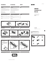
How to Detach and Attach the Front Panel
Before installing the unit, detach the front panel.
To detach
Press the RELEASE button to open up the front panel, then pull it out.
Then slide the front panel a little to the left, and pull it off towards you.
To attach
Align the parts A and B, and push the front panel until it clicks.
########
###
###
###
####
###
Parts for Installation and Connection
Componentes de instalación y conexiones
#####
The numbers in the list are keyed to those in the instructions.
Los números de la lista corresponden a los de las instrucciones.
#####
3-858-022-11 (1)
Installation/Connections
Instalación/Conexiones
###/###
Sony Corporation 1996 Printed in Singapore
XR-3300
1
× 1
2
× 1
3
× 1
456
7
× 1
8
The release key 4 is used for dismounting the unit. See the operating instructions manual for details.
La llave de liberación 4 se utiliza para desmontar la unidad. Para obtener información detalladoa,
consulte el manual de instrucciones.
######
FM/AM
Cassette Car
Stereo
× 1
× 1
× 1
× 4
To detach
Para extraerlo
###
To attach
Para instalarlo
###
B
Ejemplo de montaje
Instalación en el salpicadero
#####
####
12
3
Dashboard
Salpicadero
###
Fire wall
Panel cortafuegos
###
A
Bend these claws, if necessary.
Si es necesario, doble estas uñas.
#####
2
3
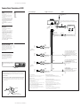
Mounting Example
Installation in the dashboard
####
######
####
Montaje de la unidad en un automóvil japonés
Usted no podrá instalar esta unidad en algunos automóviles japoneses.
En tal caso, consulte a su proveedor Sony.
Mounting the Unit in a Japanese Car
This unit may not be installed in some makes of cars. In this case,
consult your nearest Sony dealer.
1 Run a blade along the slits on
the back of the front trim and
cut it off the unit.
Pase una cuchilla a lo largo de
las ranuras de la parte posterior
del adorno frontal y córtelo.
#####
######
NISSAN
2 TOYOTA
6
max. size
M5 × 8
Tamaño
máx. M5 × 8
###
###
Bracket
Soporte
###
6
max. size
M5 × 8
Tamaño
máx. M5 × 8
###
###
to dashboard/center console
al salpicadero/consola central
###
Bracket
Soporte
###
6
max. size
M5 × 8
Tamaño
máx. M5 × 8
###
###
Bracket
Soporte
###
6
max. size
M5 × 8
Tamaño
máx. M5 × 8
###
###
to dashboard/center console
al salpicadero/consola central
####
Bracket
Soporte
###
Slit
Ranura
###
Reset Button
When the installation and connections are over, be sure to press the
reset button with a ball-point pen etc.
Tecla de reposición
Cuando finalice la instalación y las conexiones, cerciórese de presionar
la tecla de reposición con un bolígrafo, etc.
Reset button
Tecla de reposición
####
####
###
Existing parts supplied to your car
Piezas existentes suministradas con su automóvil
#####
Existing parts supplied to your car
Piezas existentes suministradas con su automóvil
#####
RELEASE button
Tecla RELEASE
###
182 mm
53 mm
1

SONY XR-3300 (E,S,C) 3-000-000-11 (1)
SONY XR-C210 (E,S,C) 3-800-373-71 (1)
Caution
• This unit is designed for negative ground 12 V
DC operation only.
• Before making connections, disconnect the
ground terminal of the car battery to avoid
short circuits.
• Connect the yellow and red power input leads
only after all other leads have been connected.
• Be sure to connect the red power input lead to
the positive 12 V power terminal which is
energized when the ignition key is in the
accessory position.
• Run all earth wires to a common earth
point.
Precauciones
• Esta unidad ha sido diseñada para
alimentación de 12 V CC, toma a tierra
negativa solamente.
• Antes de realizar las conexiones, desconecte el
conductor de puesta a masa de la batería del
automóvil a fin de evitar cortocircuitos.
• Conecte los cables conectores de alimentación
amarillo y rojo solamente después de haber
conectado los demás.
• Cerciórese de conectar el cable conector de
alimentación rojo a un terminal de 12 V
positivo que se energice al poner la llave de
encendido en la posición para accesorios.
• Conecte todos los conductores de puesta a
masa a un punto común.
#####
• #########
• #########
• #########
• #########
• ########
Connections/Conexiones/####
Connection Example Ejemplo de conexiones #####
Notes on the control leads
• The power antenna control lead (blue/white striped) supplies +12 V DC when you
turn on the unit.
• A power antenna without relay box cannot be used with this unit.
Memory hold connection
When the yellow power input lead is connected, power will always be supplied to the
memory circuit even when the ignition key is turned off.
Notes on speaker connection
• Before connecting the speakers, turn the unit off.
• Use speakers with an impedance of 4 to 8 ohms, and with adequate power handling
capacities. Otherwise, the speakers may be damaged.
• Do not connect the terminals of the speaker system to the car chassis, and do not
connect the terminals of the right speaker with those of the left speaker.
• Do not attempt to connect the speakers in parallel.
• Do not connect any active speakers (with built-in amplifiers) to the speaker
terminals of the unit. Doing so may damage the active speakers. Therefore, be sure
to connect passive speakers to these terminals.
Left
Izquierdo
##
Right
Derecho
###
Rear speakers
Altavoces traseros
###
Right
Derecho
###
Left
Izquierdo
##
Front speakers
Altavoces delanteros
####
to the +12 V power terminal which is energized in the
accessory position of the ignition key switch
Be sure to connect the black earth lead to it first.
a un terminal de alimentación de +12 V que se energice en
la posición para accesorios de la llave de encendido
Asegúrese de conectar primero a este terminal el conductor
de puesta a masa negro.
#####
###
to the +12 V power terminal which is energized at all times
Be sure to connect the black earth lead first.
a un terminal de alimentación de +12V que esté
permanentemente energizado
Asegúrese de conectar primero a este terminal el conductor
de puesta a masa negro.
####
####
Notas sobre conductores de control
• El conductor de control de la antena motorizada (con raya blanca/azul)
suministrará +12 V CC cuando encienda la unidad.
• Con esta unidad no podrá emplearse una antena motorizada desprovista de caja de
relé.
Conexión para protección de la memoria
Si conecta el conductor de entrada amarillo, el circuito de la memoria recibirá siempre
alimentación, incluso aunque ponga la llave de encendido en la posición OFF.
Notas sobre la conexión de los altavoces
• Antes de conectar los altavoces, desconecte la alimentación de la unidad.
• Utilice altavoces con una impedancia de 4 a 8 Ohmios, y con la potencia máxima
admisible adecuada, ya que de lo contrario podría dañarlos.
• No conecte los terminales del sistema de altavoces al chasis del automóvil, ni los del
altavoz izquierdo a los del derecho.
• No intente conectar los altavoces en paralelo.
• No conecte altavoces activos (con amplificador incorporado) a los terminales de
altavoces de la unidad. Si lo hiciese, podría dañar tales altavoces. Por lo tanto,
cerciórese de conectar altavoces pasivos a estos terminales.
#####
• ###
Red
Rojo
###
Yellow
Amarillo
###
Black
Negro
###
Violet
Violeta
###
Green
Verde
###
Gray
Gris
###
White
Blancao
###
LINE OUT BUS CONTROL IN
Rear speakers
Altavoces traseros
#####
from car antenna
de la antena del automóvil
#####
Fuse (10A)
Fusible (10A)
###
RCA pin cord (RC-63 (1 m), RC-64 (2 m) or RC-65 (5 m)) (not supplied)
Cable con clavijas RCA (RC-63 (1 m), RC-64 (2 m) o RC-65 (5 m)) (no suministrado)
####
Power amplifier
Amplificador de potencia
#####
Blue/white striped
Con raya blanca/azul
#####
to a power antenna relay control box
a la caja de relé de control de la antena motorizada
####
to a metal point of the car
First connect the black earth lead, then connect the yellow
and red power input leads.
a un elemento metálico del automóvil
Conecte primero el cable de tierra negro, y después, los
cables de entrada de alimentación amarillo y rojo.
###
####
AMP/ANT REM
Max. supply current 0.3 A
Corriente máx. de alimentación de 0,3 A
######
White/Black striped
Con raya negra/blanca
###
Gray/Black striped
Con raya negra/gris
###
Green/Black striped
Con raya negra/verde
###
Violet/Black striped
Con raya negra/violeta
###
5
Frequency Select Switch
The AM (FM) tuning interval is factory-set to the
9K (50K) position. If the frequency allocation
system of your country is based on 10 kHz
(200 kHz) interval, set the switch on the bottom
of the unit to the 10K (200K) position before
making connections.
Selector de frecuencia
El intervalo de sintonía de AM (FM) ha sido
ajustado en fábrica a la posición 9K (50K). Si el
sistema de asignación de frecuencias de su país
se basa en el intervalo de 10 kHz (200 kHz),
ponga este selector, situado en la base de la
unidad, en la posición 10 K (200K) antes de
realizar las conexiones.
#########################
###
###
###
Change the position with a jeweler’s screwdriver, etc.
Cambie la posición con un destornillador de relojero, etc.
#####
Note for Connecting
If there is alternator noise (a whining sound when raising engine speed), earth the master unit by
connecting it to a metal point of the car with the supplied chassis earth cord 8. Connect the
ground cord to the master unit with part 2 as shown in the illustration. (In case you do not use
part 2, take screw 7 instead.)
Nota sobre conexión
Si el alternador emite ruido (un zumbido al aumentar la velocidad del motor), conecte la unidad
principal a tierra y, para ello, enchúfela a un punto de metal del automóvil mediante el cable de
toma a tierra del chasis 8 suministrado. Conecte el cable de toma a tierra a la unidad principal
con la pieza 2 como se muestra en la ilustración. (En caso de que no emplee la pieza 2, utilice
en su lugar el tornillo 7).
###
###
###
###
To a metal point of the car
A un punto de metal del automóvil
###
2
8
-
 1
1
-
 2
2


en otros idiomas
- English: Sony XR-3300 Installation guide
Artículos relacionados
-
Sony XR-3300 Manual de usuario
-
-
-
-
-
-
-
-
-