Pioneer PDA-4004 El manual del propietario
- Categoría
- Televisores de plasma
- Tipo
- El manual del propietario

PDA-4004
VIDEO CARD
CARTE VIDEO
VIDEOKARTE
SCHEDA VIDEO
VIDEOKAART
TARJETA DE VÍDEO
Operating Instructions
Mode d’emploi
Bedienungsanleitung
Istruzioni per l’uso
Gebruiksaanwijzing
Manual de instrucciones

2
<ARE1357>
SAFETY PRECAUTIONS
En
The following symbols are found on labels
attached to the product. They alert the
operators and service personnel of this
equipment to any potentially dangerous
conditions.
WARNING
This symbol refers to a hazard or unsafe
practice which can result in personal injury
or property damage.
CAUTION
This symbol refers to a hazard or unsafe
practice which can result in severe
personal injury or death.
Thank you very much for purchasing this PIONEER
product.
Before using this unit, please carefully read the “Safety
Precautions” and these “Operating Instructions” so you
will know how to operate the Plasma Display properly.
Keep this manual in a safe place. You will find it useful in
the future.
Notes on Installation Work:
This product is marketed assuming that it is installed by
qualified personnel with enough skill and competence.
Always have an installation specialist or your dealer install
and set up the product.
PIONEER cannot assume liabilities for damage caused by
mistake in installation or mounting, misuse, modification or
a natural disaster.
Note for Dealers:
After installation, be sure to deliver this manual to the
customer and explain to the customer how to handle the
product.
WARNING:
This is a Class A product. In a domestic environment
this product may cause radio interference in which case
the user may be required to take adequate measures.

3
<ARE1357>
Fr
PRECAUTIONS DE SECURITE
DANGER
Ce symbole concerne un risque ou une
pratique dangereuse qui peut entraîner des
blessures graves ou la mort.
ATTENTION
Ce symbole concerne un risque ou une
pratique dangereuse qui peut entraîner des
blessures ou des dégâts matériels.
Les symboles qui suivent se trouvent sur les
étiquettes apposées sur le produit. Ils alertent
les utilisateurs de ce matériel ainsi que le
personnel du service aprésvente sur toutes
les situations qui présentent un danger
potentiel.
Nous vous remercions vivement d’avoir fait l’acquisition
de ce produit PIONEER.
Avant d’utiliser cet appareil veuillez lire attentivement
les “Précautions de sécurité” ainsi que le présent “Mode
d’emploi” de manière à utiliser l’écran à plasma
correctement.
Conservez ce manuel dans un endroit sûr. Il vous sera
sûrement utile dans le mois ou les années qui suivent.
Remarques sur l’installation:
Ce produit est vendu en assumant qu’il sera installé par un
personnel suffisamment expérimenté et qualifié. Faites
toujours réaliser le montage et l’installation par un spécialiste
ou par votre revendeur.
PIONEER ne peut être tenu responsable pour tout dommage
causé par une erreur d’installation ou de montage, une
mauvaise utilisation ou un désastre naturel.
Remarque pour le revendeur:
Après l’installation, assurez-vous de remettre ce mode
d’emploi à l’utilisateur et de lui expliquer comme utiliser ce
produit.
AVERTISSEMENT:
Il s’agit d’un produit de classe A. Dans un
environnement domestique, ce produit risque de
provoquer des interférences radio; dans ce cas,
l’utilisateur est prié d’engager des mesures
adéquates.

4
<ARE1357>
SICHERHEITSMASSNAHMEN
Ge
WARNUNG
Dieses Symbol weist auf eine gefährliche
oder unsichere Handlung hin, die zu
schweren Personenschäden oder Tod
führen kann.
VORSICHT
Dieses Symbol weist auf eine gefährliche
oder unsichere Handlung hin, die zu
Personenoder Sachschäden führen kann.
Die nachstehenden Symbole befinden sich auf
dem Gerät angebrachten Aufklebern. Sie
machen den Benutzer und das
Wartungspersonal auf mögliche Gefahren
aufmerksam.
Herzlichen Dank, daß Sie sich für den Kauf dieses
PIONEER-Produktes entschieden haben.
Bevor Sie dieses Gerät benutzen, lesen Sie bitte
sorgfältig den Abschnitt “Sicherheitsmaßnahmen” und
diese “Bedienungsanleitung“ durch, um eine
problemlose Verwendung des Plasma-Displays zu
gewährleisten. Bewahren Sie diese Anleitung an einem
sicheren Ort auf. Sie wird Ihnen in Zukunft nützliche
Dienste leisten.
Hinweise zur Installation:
Dieses Produkt wird unter der Annahme vertrieben, daß es
von einem qualifizierten Techniker installiert wird, der über
die erforderlichen technischen Kenntnisse und Erfahrung für
diese Arbeiten verfügt. Zur Installation und dem Setup dieses
Geräts ist daher stets ein damit vertrauter
Kundendiensttechniker oder der Verkaufshändler zur Rate
zu ziehen. PIONEER übernimmt keine Haftung für Schäden,
die durch Fehler bei der Installation bzw. der Befestigung,
durch unsachgemäße Verwendung, Modifikation sowie
durch Naturkatastrophen entstanden sind.
Hinweis für den Händler:
Nach der Installation diese Anleitung dem Kunden
aushändigen und die Verwendung des Produkts erläutern.
Warnung:
Dieses produkt entspricht dem EMV-Standard der
Klasse A. Produkte dieser Klasse sind nur für den
industriellen Einsatz geeignet und dürfen in
Wohnund Gewerbegebieten nicht ohne
ausreichende Entstörungsmaßnahmen
betrieben werden.

5
<ARE1357>
SAFETY PRECAUTIONS................................. 2
BEFORE PROCEEDING..................................... 8
How to use this manual .................................8
SUPPLIED ACCESSORIES ...............................8
PANEL FEATURES AND FUNCTIONS .............9
Connection Panels
(PDP-V402EA&PDA-4004) .............................. 9
INSTALLING THE VIDEO CARD ..................... 11
Connecting this unit to the monitor .......... 11
Installing the video card ...........................12
Installing the terminals.............................13
VIEWING IMAGES ON YOUR
PLASMA DISPLAY ..........................................14
HOW TO ADJUST PICTURE QUALITY.......... 16
RGB-1 (BNC) or RGB-2 (MINI D-SUB) Input .. 16
With RGB-1, when inputting RGB
output from a unit with a Euro AV
(SCART) terminal ...................................... 20
Video or Y/C Input ..................................... 24
CONNECTIONS...............................................28
Connecting Video
Devices to the Display .............................. 28
OTHERS........................................................... 34
Troubleshooting ........................................34
Specifications ............................................ 37
CONTENTES
En

6
<ARE1357>
PRECAUTIONS DE SECURITE ........................3
AVANT DE COMMENCER ................................ 8
Comment utiliser ce mode d'emploi ........... 8
ACCESSOIRES FOURNIS .................................8
CARACTERISTIQUES ET FONCTIONS
DES PANNEAUX...............................................9
Panneau de raccordement
(PDP-V402EA et PDA-4004) ........................9
INSTALLATION DE LA CARTE VIDÈO .............11
Connexion de I'appareil à I'écran ..............11
Installation de la carte vidèo ......................... 12
Installation des bornes ............................. 13
VISUALISATION DES IMAGES
SUR L’ECRAN A PLASMA .............................. 14
COMMENT REGLER LA QUALITE
DE L’IMAGE..................................................... 16
Entrée RGB-1 (BNC) ou
RGB-2 (MINI D-SUB) ..................................17
Avec RGB-1, lors de la connexion d’une
sortie RGB à une unité équipée d’un
terminal Euro AV (SCART) ....................... 21
Entrée vidéo ou Y/C .................................. 25
CONNEXIONS.................................................28
Connexion d'équipments
vidéo à l'écran ...........................................28
AUTRES........................................................... 35
Dépannage .................................................35
Spécifications ............................................ 38
SOMMAIRE
Fr

7
<ARE1357>
SICHERHEITSMASSNAHMEN....................... 4
VOR DER INBETRIEBNAHME ..........................8
Verwendung dieser Anleitung ..................... 8
MITGELIEFERTES ZUBEHÖR ........................... 8
TASTEN, EINSTELLUNGEN
UND FUNKTIONEN ........................................... 9
Anschlußleiste
(PDP-V402EA und PDA-4004) ..................... 9
INSTALLIEREN DER VIDEOKARTE ................ 11
Anschluß dieses Geräts am Monitor ....... 11
Installieren der Videokarte........................12
Installieren der Anschlüsse .......................... 13
BILDWIEDERGABE AUF IHREM
PLASMA-DISPLAY ..........................................14
EINSTELLEN DER BILDQUALITÄT ................16
RGB-1 (BNC) oder
RGB-2 (MINI D-SUB) Eingang ..................17
Bei Empfang von RGB-Signalen eines
Geräts mit EURO A/V-Anschluß
(SCART) über RGB-1 .................................21
Video oder Y/C Eingang............................ 25
ANSCHLÜSSE.................................................28
Anschluß von Videogeräten
an das Display ...........................................28
VERSCHIEDENES ...........................................36
Fehlerbeseitigung ..................................... 36
Technische Daten ...................................... 39
Ge
INHALT

8
<ARE1357>
En/Fr/Ge
BEFORE PROCEEDING
AVANT DE COMMENCER
VOR DER INBETRIEBNAHMA
How to use this
manual
This manual is set up to follow the
course of actions and operations in
the order that would seem most
logical for someone setting up this
unit.
Once the unit has been taken out
of the box, and it has been con-
firmed that all the parts have been
received, the section “Connecting
this unit to the monitor” starting on
page 11 outlines the procedure for
connecting this unit to the plasma
display, PDP-V402EA.
After the unit is connected to the
plasma display, use this instruction
manual in conjunction with the in-
struction manual included with the
PDP-V402EA to control your system
To familiarize yourself with the
parts, buttons, and controls of this
unit, the plasma display, and the re-
mote control unit, please refer to
the section “PANEL FEATURES
AND FUNCTIONS” on page 9 and
the corresponding section in the in-
struction manual for the PDP-
V402EA.
Comment utiliser ce
mode d’emploi
Ce mode d’emploi s’organise
autour d’explications classées dans
l’ordre qui nous a paru le plus
logique à quelqu’un qui prendrait
possession de l’écran à plasma
pour la première fois.
Une fois que vous avez déballé
l’appareil et que vous avez bien
tous les éléments requis, lisez la
section “Connexion de l'appareil à
l'écran” qui commence à la page␣ 11
pour plus de détails sur la
procédure à suivre pour brancher
cet appareil à l’écran à plasma PDP-
V402EA.
Une fois que l’appareil est branché
à l’écran à plasma, utilisez ce mode
d’emploi en même temps que celui
du PDP-V402EA pour commander
le système.
Pour vous familiariser avec les
éléments, les boutons et les
commandes de cet appareil, avec
l’écran à plasma et avec la
télécommande, reportez-vous à la
section “CARACTERISTIQUES ET
FONCTIONS DES PANNEAUX” à la
page 9 et à la section
correspondante dans le mode
d’emploi du PDP-V402EA.
Verwendung dieser
Anleitung
Die in dieser Anleitung enthaltenen
Hinweise sind in einer Reihenfolge
angeordnet, die der logischen
Vorgehensweise beim Aufstellen
und der Inbetriebnahme dieses
Geräts entspricht.
Nachdem das Display aus dem
Versandkarton genommen und alle
mitgelieferten Teile auf
Vollständigkeit überprüft wurden,
sind die Anweisungen im Abschnitt
“Anschluß dieses Geräts am Moni-
tor”, beginnend auf Seite 11; an
dieser Stelle wird die
Vorgehensweise zum Anschluß
dieses Geräts an das Plasma-Dis-
play PDP-V402EA erläutert.
Nachdem das Gerät mit dem
Plasma-Display verbunden wurde,
ist diese Anleitung in Verbindung
mit der Bedienungsanleitung des
PDP-V402EA zur Steuerung des
Systems zu verwenden.
Es wird empfohlen, den Abschnitt
“TASTEN, EINSTELLUNGEN UND
FUNKTIONEN” auf Seite 9 und der
entsprechenden Kapitel der
Bedienungsanleitung des PDP-
V402EA durchzulesen, um sich mit
den Tasten und
Bedienungselementen dieses
Geräts, des Plasma-Displays und
der Fernbedienungseinheit vertraut
zu machen.
SUPPLIED ACCESSORIES
ACCESSOIRES FOURNIS
MITGELIEFERTES ZUBEHÖR
Tick the box of accessories to
confirm they have been properly
provided.
1 Terminal name label
&
2 Screw &
3 Operating Instructions &
Cocher la case en face des
accessoires afin de confirmer que
ceux-ci sont bien présents.
1 Etiquettes nominatives des
bornes
&
2 Vis &
3 Mode d’emploi &
Zur Überprüfung, ob alle
angegebenen Zubehörteile
ordnungsgemäß geliefert wurden,
kreuzen Sie jeweils das betreffende
Kästchen
an.
1 Anschlussetikett
&
2 Schraube &
3 Bedienungsanleitung &

9
<ARE1357>
En/Fr/Ge
<Control Panel>
1 STANDBY/ON indicator
The indicator is red when in
standby mode and turns green
when the power to the display
is turned on.
2 STANDBY/ON button
Press to turn the power to the
display on and off.
3 INPUT button
Press to switch the various in-
put functions.
4 MENU button
Press to enter the menu screen
and exit from it.
5 ADJUST button
Use the +/– buttons to adjust pic-
ture quality.
6 SET button
Press to finalize menu selections
when adjusting picture quality.
<Panneau de commande>
1 Témoin STANDBY/ON (= en at-
tente/marche)
Ce témoin est rouge lorsqu’il est
dans le mode en attente et
devient vert lorsque l’écran est
mis sous tension.
2 Bouton STANDBY/ON (= Ali-
mentation)
Appuyer sur ce bouton pour
mettre l’écran sous tension et
hors tension
3 Bouton INPUT (= entrée)
Appuyer sur ce bouton pour la
commande des différentes
fonctions d’entrée
4 Bouton MENU
Appuyer sur ce bouton pour
entrer dans l’écran menu et en
sortir.
5 Bouton ADJUST (= réglage)
Utiliser les boutons +/- pour
ajuster la qualité de l’image
6 Bouton SET (= sélection)
Appuyer sur ce bouton pour
finaliser les sélections de menu lors
du réglage de la qualité de l’image.
PANEL FEATURES AND FUNCTIONS
CARACTERISTIQUES ET FONCTIONS DES PANNEAUX
TASTEN, EINSTELLUNGEN UND FUNKTIONEN
Anschlußleiste (PDP-
V402EA und PDA-
4004)
<Bedienungstasten>
1 STANDBY/ON-Leuchtdiode
Die Leuchtdiode leuchtet rot auf,
wenn die
Bereitsschaftsschaltung an ist,
und wechselt zu grün, wenn das
Display eingeschaltet ist.
2 POWER-Taste
Mit dieser Taste wird das Gerät
ein- und ausgeschaltet.
3 INPUT-Taste
Mit dieser Taste werden die
Eingänge umgeschaltet.
4 MENU-Taste
Mit dieser Taste wird die
Menüoberfläche aktiviert.
5 ADJUST-Taste
Mit den +/– Tasten werden die
Einstellungen vorgenommen.
6 SET-Taste
Mit dieser Taste werden die
Einstellungen aktiviert und
bestätigt.
Connection Panels
(PDP-V402EA&PDA-
4004)
Panneau de
raccordement (PDP-
V402EA et PDA-4004)
STANDBY
/ON
INPUT
MENU
ADJUST
SET
<Control Panel>
<Panneau de commande>
<Seitliche Tasten>

10
<ARE1357>
En/Fr/Ge
PANEL FEATURES AND FUNCTIONS
CARACTERISTIQUES ET FONCTIONS DES PANNEAUX
TASTEN, EINSTELLUNGEN UND FUNKTIONEN
VD HD B G R C Y OUT IN
75 2.2k
OFF ON
(
Ω
)
(H/V SYNC) RGB-1 (ON SYNC) Y/C
SYNCREMOTE G ON SYNC
VIDEO RS-232CRGB-2
OFF ON
8
97
-0=~!@
#
$%^ & (*
<Rear Panel Terminals/Con-
nections to Power Source>
RGB-2 input terminals
7 Remote control out switch (ON/
OFF)
This switch will output remote
control commands from the
RGB-2 (D-SUB 15-pin) terminal
to control external peripheral
devices planned for future sales
release. Normally be sure to
use set to OFF.
8 MINI D-SUB 15-pin terminal
9 G on Sync mode selection
switch (ON/OFF)
If the images become greenish
when an external device is con-
nected to the RGB-2 input ter-
minal, turn ON the G on SYNC
mode. Normally set to OFF.
RGB-1 input terminals
0 Sync Signal Input Impedance
switch (75 Ω/2,2 kΩ)
- Vertical Sync Signal Input ter-
minal: (75 Ω/2,2 kΩ, switchable
with the Sync Signal Input Im-
pedance switch)
= Horizontal or Composite Sync
Signal Input terminal: (75 Ω/2,2
kΩ, switchable with the Sync
Signal Input Impedance switch)
~ Blue Signal Input terminal: 75 Ω
! Green or Green with Sync Sig-
nal Input terminal (ON SYNC):
75 Ω
@ Red Signal Input terminal: 75 Ω
Y/C input terminals
# Color Signal Input terminal: 75 Ω
$ Luminance Signal Input termi-
nal: 75 Ω
VIDEO input/output terminals
% Video Output terminal: 75 Ω
^ Video Input terminal: 75 Ω
& Control Signal Input terminal
(RS-232C compliance)
* AC inlet
( MAIN POWER switch
<Bornes du panneau arrière/
Connexions à la source
d’alimentation>
Bornes d’entrée RGB-2
7 Contacteur d’émission de
commandes à distance (ON/OFF
= MARCHE/ARRET)
Ce contacteur émet les
commandes à distance en prov-
enance de la borne RGB-2 (D-SUB
15 broches) vers les périphériques
externes qui seront vendus à
l’avenir.
S’assurer que le réglage est sur
OFF.
8 Borne 15 broches MINI D-SUB
9 G sur bouton de sélection du
mode Sync (ON/OFF = MARCHE/
ARRET)
Si les images deviennent verdâtres
lorsqu’un dispositif extérieur est
raccordé au terminal d’entrée
RGB-2, amener G sur le mode
SYNC. Normalement, celui-ci est
réglé sur OFF (= arrêt).
Bornes d’entrée RGB-1
0 Commutateur d’impédance
d’entrée du signal de
synchronisation (75 Ω/2,2 kΩ)
- Borne d’entrée du signal de
synchronisation vertical (75 Ω/2,2
kΩ, commutable avec le
commutateur d’impédance
d’entrée du signal de
synchronisation)
= Borne d’entrée du signal de
synchronisation horizontal ou
composite : (75 Ω/2,2 kΩ, commut-
able avec l’interrupteur
d’impédance d’entrée du signal de
synchronisation)
~
Borne d’entrée du signal bleu: 75 Ω
!
Borne d’entrée du signal vert ou
vert avec signal de synchronisation
(ON SYNC) : 75 Ω.
@ Borne d’entrée du signal rouge :
75 Ω
Bornes d’entrée Y/C
# Borne d’entrée du signal couleur:
75 Ω
$ Borne d’entrée du signal de lumi-
nance : 75 Ω
Bornes d’entrée/sortie VIDEO
% Borne de sortie vidéo : 75 Ω
^ Borne d’entrée vidéo : 75 Ω
& Borne d’entrée du signal de
commande (Conforme au stan-
dard RS-232C)
* Prise c.a.
( Interrupteur général POWER
<Anschlußleiste>
RGB 2-Eingang
7 EIN-/AUS-Schalter der
Fernbedienung (ON/OFF)
Mit diesem Schalter können
Fernbedienungsbefehle über
den Anschluß RGB-2 (D-SUB,
15-Pin-Buchse) ausgegeben
werden, um zukünftiges
Zubehör zu steuern.
Für den Normalbetrieb
unbedingt auf OFF stellen.
8 MINI D-SUB 15-Pin-Eingang
9 G an Sync-Moduswählschalter
(ON/OFF)
Wird der Bildschirm grünlich,
sobald ein externes Gerät an der
Input-Schnittstelle von RGB - 2 -
angeschlossen wird, schalten Sie
G am Sync-Moduswählschalter
auf ON (EIN), während es
normalerweise auf OFF (AUS)
steht.
RGB 1-Eingang
0 Synchronsignal-Eingangs-
Impedanz-Schalter (75 Ω/2,2 kΩ).
- Vertikaler Synchronsignal-
Eingang (75 Ω/2,2 kΩ, einstellbar
mit dem Synchronsignal-
Eingangs-Impedanz-Schalter).
= Horizontaler oder kombinierter
Synchroneingang: (75 Ω/2,2 kΩ,
einstellbar mit dem
Synchronsignal-Eingangs-
Impedanz-Schalter).
~ Blaues Signal: 75 Ω
! Grünes Signal oder Grün mit
Synchronsignal-Eingang (ON
SYNC): 75 Ω
@ Rotes Signal: 75 Ω
Y/C Eingang
# Farbsignal Eingang: 75 Ω
$ Helligkeitssignal-Eingang: 75 Ω
VIDEO-Eingang/Ausgang
% Video-Ausgang: 75 Ω
^ Video-Eingang: 75 Ω
& Kontrollsignal-Eingang (RS-
232C kompatibel)
* Netzanschluß
( Netzschalter (MAIN POWER)
<Rear Panel Terminal/Connections to Power Source>
<Bornes du panneau arrière/Connexions à la source d’alimentation>
<Hintere Anschlußleiste / Netzanschluß>

11
<ARE1357>
En/Fr/Ge
Connecting this unit
to the monitor
This unit is to be used only when
connected to the plasma display,
PDP-V402EA. Follow the procedure
on this page to connect this unit to
the plasma display.
Before connecting this unit to the
display, please be sure to do the
following:
• Undo any component or personal
computer connections that may
have already been made to the
plasma display.
• Make sure that the power of the
plasma display is turned off, and
is unplugged from the wall out-
let.
Precautions when connecting this
unit to the display
When the doors on the display are
opened to make connections, be
sure to avoid letting the screw or
their respective parts fall into open-
ings on the units.
When connecting (this unit) to the
plasma display, always install with
the display upright. Dropping a
screw into the display may damage
it.
CAUTION
• This unit is designed only for con-
nection to the plasma display,
PDP-V402EA. Do not alter or
modify this unit in any way as it
may cause this unit to perform
abnormally and/or may cause the
plasma display to malfunction.
Notes for Customers:
This product is marketed assum-
ing that it is installed by quali-
fied personnel with enough skill
and competence.
Notes for Dealers:
The procedure for connecting
this unit to the main unit is de-
scribed below. Should screws or
other substances fall into the
main unit during installation,
please contact a nearby PIO-
NEER service center as soon as
possible. Continuing work under
these circumstances may cause
damage.
Connexion de
l’appareil à l’écran
Cet appareil ne doit être utilisé que
quand il est connecté à l’écran à
plasma PDP-V402EA. Suivez la
procédure décrite dans cette page
pour effectuer cette connexion.
Avant de connecter cet appareil à
l’écran, n’oubliez pas d’effectuer les
opérations suivantes:
• Annulez toute connexion
d’appareil ou d’ordinateur per-
sonnel déjà effectuée sur l’écran
à plasma.
• Assurez-vous que l’écran à
plasma est hors tension et
débranché de la prise murale.
Précautions pour connecter
l’appareil à l’écran
Lorsque l’écran est ouvert en vue
d’effectuer les connexions, prenez
garde de ne pas faire tomber les vis
ou autre élément de fixation à
l’intérieur.
Lors de la connexion (de cet
appareil) à l’écran à plasma,
réalisez toujours l’intallation avec
l’écran en position verticale. Faire
tomber une vis dans l’écran risque
de l’endommager.
ATTENTION
• Cet appareil est conçu pour être
branché uniquement sur l’écran
à plasma PDP-V402EA. Ne le
modifiez d’aucune manière que
ce soit, car cela risquerait
d’entraîner un mauvais
fonctionnement et/ou de causer
un dysfonctionnement de l’écran
à plasma.
Remarques pour le client:
Ce produit est vendu en
assumant qu’il sera installé par
un personnel suffisamment
expérimenté et qualifié.
Remarque pour le revendeur:
La procédure pour connecter cet
appareil à l’appareil principal est
décrite ci-dessous. Si une vis ou
un autre objet tombait à
l’intérieur de l’appareil principal
pendant l’installation, veuillez
contacter un centre de service
PIONEER, aussitôt que possible.
Continuer l’installation dans ces
conditions pourrait entraîner des
dommages.
Anschluss dieses
Geräts am Monitor
Dieses Gerät ist ausschließlich zur
Verwendung in Verbindung mit
dem Plasma-Display PDP-V402EA
bestimmt. Die auf dieser Seite
gegebenen Anweisungen
ausführen, um dieses Gerät am
Plasma-Display anzuschließen.
Bevor dieses Gerät mit dem Display
verbunden wird, müssen die
nachfolgenden Anweisungen
ausgeführt werden:
• Alle bereits vorgenommenen
Verbindungen zwischen einem
Personal-Computer oder einer
anderen Komponente und dem
Plasma-Display müssen gelöst
werden.
• Sich vergewissern, dass die
Stromversorgung zum Plasma-
Display ausgeschaltet und das
Netzstecker aus der
Wandsteckdose abgezogen
wurde.
Vorsichtshinweise zum Anschluss
dieses Geräts am Display
Wenn die klappen an dem Display
zur Durchführung der Anschlüsse
abgenommen werden, ist darauf zu
achten, dass keine der Schrauben
oder andere Teile in die Öffnungen
fallen können. Wenn (dieses Gerät)
mit dem Plasma-Display verbunden
wird, muss das Display aufrecht
installiert werden. Darauf achten,
dass keine Schraube in das Display
fällt, da dies eine Funktionsstörung
verursachen kann.
VORSICHT
• Dieses Gerät ist ausschließlich zum
Anschluss an den Plasma-Display
PDP-V402EA bestimmt. Das Gerät
darf nicht auf irgendeine Weise
modifiziert oder umgebaut werden,
da hierdurch ein normaler Betrieb
nicht mehr möglich ist und/oder zu
Funktionsstörung am Plasma-Dis-
play führen kann.
Hinweise für den Kunden:
Dieses Produkt wird unter der
Annahme vertrieben, dass es von
einem qualifizierten Techniker
installiert wird, der über die
erforderlichen technischen
Kenntnisse und Erfahrung für
diese Arbeiten verfügt.
Hinweis für den Händler:
Die Vorgehensweise beim
Anschluss dieser Einheit an das
Hauptgerät wird nachstehend
beschrieben. Sollte eine Schraube
oder ein anderes Teil bei der In-
stallation in das Hauptgerät fallen,
muss unverzüglich eine PIONEER-
Kundendienstwerkstatt
benachrichtigt werden. Falls die
Anschlussarbeiten unter diesen
Umständen fortgesetzt werden,
kann ein Geräteschaden die Folge
sein.
INSTALLING THE VIDEO CARD
INSTALLATION DE LA CARTE VIDÈO
INSTALLIEREN DER VIDEOKARTE

12
<ARE1357>
En/Fr/Ge
1 2
3
INSTALLING THE VIDEO CARD
INSTALLATION DE LA CARTE VIDÈO
INSTALLIEREN DER VIDEOKARTE
Installing the video
card
Installation de la
carte vidèo
Installieren der
Video karte
• Take care not to damage or
modify the internal cables and
units.
• The circuit boards and soldered
parts of the built-in options are
exposed. As these may be dam-
aged by the static electricity
charged in the human body, dis-
charge the static electricity by
touching a metallic object before
handling a built-in option.
• Do not touch a circuit board sur-
face or soldered part but hold cir-
cuit board by the metallic bracket
or edge.
• Before you install or remove the
video card and terminal panel,
turn the main power switch OFF,
and disconnect the AC power
point.
• Never subject the video card to
static electricity.
Static electricity can destroy the
circuit. During installation, take
care to avoid creating static elec-
tricity, and do not place the video
card on top of easily charged ob-
jects.
• Install the video card and termi-
nal panel at the same time. If only
one of them is installed or one of
them is installed incorrectly, the
power will not turn on. If this hap-
pens, the following warning sign
occurs.
(1) If the video card is not in-
stalled properly:
The standby indicator of the
plasma display repeatedly
flashes two times.
(2) If the terminal panel is not in-
stalled properly:
The standby indicator of the
plasma display repeatedly
flashes three times.
• The video card and terminal
panel are not designed for re-
peated installation and removal.
Accordingly, once they have been
installed on the plasma display,
avoid removing them. Repeated
installation and removal may
cause them to break.
• Veiller à ne pas endommager les
câbles et les unités internes et à ne
pas les modifier.
• Les circuits imprimés et les
composants soudés des options
intégrés sont à nu. Ces éléments
pouvant être endommagés par
l'électricité statique du corps, il
convient de toucher un objet
métallique avant de manipuler une
option intégrée.
• Ne pas toucher la surface du circuit
imprimé ni les composants soudés
mais saisir le circuit imprimé par le
support métallique ou le bord.
• Avant d’installer ou de déposer la
carte vidéo et le panneau de bornes,
coupez l’interrupteur principal (OFF)
débranchez la fiche du câble
d’alimentation.
• Ne soumettez en aucun cas la carte
vidéo à de l’électricité statique.
L’électricité statique peut détruire le
circuit. Pendant l’installation, veillez
à ne pas créer d’électricité statique
et ne posez pas la carte vidéo sur
des objets qui se chargent
facilement d’électricité statique.
• Installez la carte vidéo et le panneau
de bornes en même temps. Si vous
n’installez que l’un de ces deux
éléments ou si l’un d’eux est installé
incorrectement, le système ne se
mettra pas sous tension. Si cela se
produit, le signe d’avertissement
suivant s’affiche.
(1) Si la carte vidéo n’est pas
correctement installée :
L’indicateur de mode de veille de
l’écran à plasma clignote deux
fois de manière répétitive.
(2) Si le panneau de bornes n’est
pas correctement installé :
L’indicateur de mode de veille de
l’écran à plasma clignote trois
fois de manière répétitive.
• La carte vidéo et le panneau de
bornes ne sont pas conçus pour des
installations et des déposes
répétées. Aussi, lorsqu’ils ont été
installés sur l’écran à plasma, veillez
à ne pas les déposer. Des installa-
tions et déposes répétées peuvent
les endommager.
• Achten Sie darauf, daß die internen
Kabel und die Geräte nicht
beschädigt werden.
• Die Leiterplatten und die gelöteten
Teile der eingebauten Optionen
liegen frei. Da diese durch statische
Elektrizität im menschlichen Körper
beschädigt werden können,
berühren Sie einen metallischen
Gegenstand, um die statische
Elektrizität zu entladen, bevor Sie
eine eingebaute Option handhaben.
• Berühren Sie die Oberfläche der
Leiterplatte oder die gelöteten Teile
nicht, sondern halten Sie die
Leiterplatte an der metallischen
Halterung oder an der Kante.
• Vor Ein- oder Ausbau von Videokarte
und Anschlussplatine, den
Bildschirm ausschalten und den
Netzstecker ziehen.
• Die Videokarte vor statischer
Elektrizität schützen.
Statische Elektrizität kann die Karte
beschädigen. Beim Einbau das
Entstehen von statischer Elektrizität
vermeiden und die Videokarte nicht
auf Gegenstände platzieren, die sich
leicht aufladen.
• Videokarte und Anschlussplatine
gleichzeitig einbauen. Falls eine der
beiden nicht korrekt installiert ist,
lässt sich der Bildschirm nicht
einschalten. In diesem Fall erscheint
das folgende Warnsymbol:
(1) Falls die Videokarte falsch
eingebaut wurde:
Die Bereitschaftsanzeige des
Bildschirms blinkt wiederholt
zweimal hintereinander auf.
(2) Falls die Anschlussplatine falsch
eingebaut wurde:
Die Bereitschaftsanzeige des
Bildschirms blinkt wiederholt
dreimal hintereinander auf.
• Videokarte und Anschlussplatine
sind nicht auf wiederholten Ein- und
Ausbau ausgelegt. Daher sollten sie
nach der Installation im Bildschirm
nicht mehr ausgebaut werden.
Wiederholter Ein- und Ausbau kann
zu Schäden führen.
Boss
Bossage
Nase
Boss
Bossage
Nase
Boss
Bossage
Nase
Boss
Bossage
Nase

13
<ARE1357>
En/Fr/Ge
1 2
Installing the termi-
nals
Installation des
bornes
Installieren der
Anschlüsse
INSTALLING THE VIDEO CARD
INSTALLATION DE LA CARTE VIDÈO
INSTALLIEREN DER VIDEOKARTE
1 Remove the video card input
terminal installation hole pro-
tection door on the terminal
panel section of plasma display
by removing the retaining
screws.
2 Fit the circuit boad between the
slits at each end of the opening.
3 Insert the terminal panel
straight and push it in all the
way.
4 Make sure that the terminal
panel is inserted firmly and
completely to the bottom, then
secure the terminal panel using
the screws removed in step 1
above.
5 Attach the provided label.
1 Déposez le panneau de protection
de l’orifice d’installation des bornes
d’entrée de la carte vidéo de la sec-
tion des bornes de l’écran à plasma
en retirant les vis de retenu.
2 Fixez la carte entre les fentes situées
de part et d’autre de l’ouverture.
3 Insérez le panneau de bornes
verticalement et enfoncez-le à fond.
4 S'assurer que le panneau de
bornes est inséré
soigneusement et
complètement jusqu'en bas,
puis fixer le panneau de bornes
au moyen des vis qui ont été
retirées à l'étape 1 ci-dessus.
5 Fixer l'étiquette fournie.
1 Die Schutzabdeckung von der
Öffnung für die Videokarten-
Eingangsplatine von der
Anschlussleiste des Plasma-Dis-
plays abnehmen indem die
Befestigungsschrauben entfernt
werden.
2 Die Anschlussplatine in die Schlitze
an den Enden der Öffnung
einpassen.
3 Die Anschlussplatine gerade bis
zum Anschlag einführen.
4 Achten Sie darauf, daß die
Klemmenleiste richtig und
vollständig an der Unterseite
eingesteckt ist, und sichern Sie
danach die Klemmenleiste mit
den im obigen Schritt 1
entfernten Schrauben.
5 Bringen Sie das mitgelieferte
Etikett.
1 Loosen the screw in the door at
the rear of the plasma display.
(The screw is constructed so
that it cannot be separated from
the cover.)
2 Open the door.
3 Install the video card to the four
bosses so that the connectors
are at the bottom. Make sure
that the four bosses retain the
circuit board firmly and there is
no fear of board separation.
4 Plug the internal wires into the
connectors. Make sure that the
connector is inserted firmly and
completely up to the root.
5 Close the door and tighten the
cover screw.
1 Desserrez la vis du panneau à
l’arrière de l’écran à plasma. (La
vis est conçue de telle manière
qu’elle ne peut être séparée du
panneau.)
2 Ouvrez le panneau.
3 Installez la carte vidéo sur les
quatre bossages de façon à ce
que les connecteurs soient en
bas. S'assurer que les quatre
bossages maintiennent
soigneusement le circuit
imprimé et qu'il n'y a aucun ris-
que de voir le circuit se séparer.
4 Branchez les fils internes sur les
connecteurs. S'assurer que le
connecteur est inséré à fond et
complètement jusqu'à la base.
5 Refermez le panneau et serrez
la vis du panneau.
1 Die Schraube der Klappe an der
Rückseite des
Plasmabildschirms lockern. (Die
Schraube lässt sich nicht von
der Abdeckung lösen.)
2 Die Klappe öffnen.
3 Die Videokarte auf die vier
Nasen aufsetzen, sodass die
Anschlüsse nach unten weisen.
Achten Sie darauf, daß die vier
Nasen die Leiterplatte richtig
halten und die Leiterplatte nicht
abgetrennt werden kann.
4 Die internen Kabel mit den
Anschlüssen verbinden. Achten
Sie darauf, daß der Stecker
richtig eingesteckt ist und bis
zum Anschlag in dem Anschluß
steckt.
5 Die Klappe schließen und die
Schraube festziehen.
4
5
3, 4
5

14
<ARE1357>
En/Fr/Ge
1 Input the power to the main unit.
The standby indicator will flash in red for about 4
seconds. The display then enters standby state and
the indicator remains lit.
NOTE:
The buttons on the main unit and remote control unit,
and the external control commands are not accepted
by the display unit while the standby indicator is flash-
ing in red.
If the optional video card (PDA-4004) is not installed
properly, the STANDBY indicator blinks as described
below to inform the use of abnormality.
• Blinking twice
Only the terminals are installed:
Install the video card.
• Blinking three times
Only the video card is installed:
Install the terminals.
2 Turn on the Display.
The STANDBY indicator turns green.
3 Select an input source.
• Press the INPUT switching button on the main unit.
Each time press changes the input source as fol-
lows:
• To choose an input source with the remote con-
trol, press the INPUT SELECT button.
• The function cannot be switched at the MENU
screen.
“NO SYNC!” is displayed if no signal is being input .
“OUT OF RANGE!” is displayed if the signal being
input cannot be processed on this set.
4 After use, turn off the power.
1 Turn off the power.
The standby indicator flashes in red for about 4 sec-
onds, then remains lit (standby state).
2 Turn off the MAIN POWER switch on the main
unit.
The STANDBY/ON indicator will dim and the power
to the unit will be turned off.
NOTES:
• The buttons on the main unit and remote control
unit, and the external control commands are not ac-
cepted by the display while the standby indicator is
flashing in red.
• Do not display the same image (still images, etc.)
for a long time as the image may stick onto the
screen.
VIEWING IMAGES ON YOUR PLASMA DISPLAY
VISUALISATION DES IMAGES SUR L’ECRAN A PLASMA
BILDWIEDERGABE AUF IHREM PLASMA-DISPLAY
STANDBY
/ON
INPUT
MENU
ADJUST
SET
OUT IN
VIDEO RS-232C
M
E
N
U
IN
P
U
T
S
E
L
E
C
T
V
ID
E
O
Y
/C
R
G
B
1
STA
N
D
BY/ON
R
G
B
2
S
E
Remote control
Commande à distance
Fernbedienung
Main unit
Unité principale
Hauptgerät
STANDBY/ON
STANDBY
/ON
STANDBY
/ON
VIDEO
INPUT
V
I
DEO
1
STANDBY/ON
STANDBY
/ON
STANDBY
/ON
2
STANDBY
/ON
STANDBY
/ON
VIDEO Y/C
RGB 2 RGB 1
Remote control
Commande à distance
Fernbedienung
Main unit
Unité principale
Hauptgerät
Remote control
Commande à distance
Fernbedienung
Main unit
Unité principale
Hauptgerät
1
2
3
4
2,4
3
1,4
2,4
3

15
<ARE1357>
En/Fr/Ge
VIEWING IMAGES ON YOUR PLASMA DISPLAY
VISUALISATION DES IMAGES SUR L’ECRAN A PLASMA
BILDWIEDERGABE AUF IHREM PLASMA-DISPLAY
1 Alimentation de l’écran en énergie
Le témoin en attente rouge clignote pendant 4
secondes environ. Ensuite, l’écran passe en mode
attente et ce témoin reste allumé.
NOTE:
Les boutons de l’unité principale et de la commande
à distance, ainsi que les instructions de commande
extérieures ne sont pas acceptés par l’écran tant que
le témoin en attente rouge clignote.
Si la carte vidéo en option (PDA-4004) n'est pas
correctement installée, le témoin STANDBY clignote
comme il est dit ci-dessous pour signaler cette
anomalie.
• Deux clignotements
Seuls les bornes sont installées:
Installer la carte vidéo.
• Trois clignotements
Seule la carte vidéo est installée:
Installer les bornes.
2 Allumage de l’écran
Le témoin STANDBY (en attente) devient vert.
3 Sélection d’une source d’entrée
• Pousser sur le bouton de commutation INPUT
(entrée) de l’unité principale.
Chaque pression modifie la source d’entrée comme
suit :
• Pour sélectionner une source d’entrée avec la
commande à distance, appuyer sur le bouton IN-
PUT SELECT (= sélection d’entrée)
• La fonction ne peut pas être commutée à l’écran
MENU.
«NO SYNC␣ !» s’affiche en l’absence de réception d’un
signal à la sélection de RGB-1 ou de RGB-2.
«OUT OF RANGE» s’affiche si le signal reçu ne peut
pas être traité par cet appareil.
4 Après utilisation, mettre hors ten-
sion
1 Mise hors tension
Le témoin en attente rouge clignote pendant environ
4 secondes, puis reste allumé (état en attente).
2 Eteindre l’interrupteur MAIN POWER (= sur l’unité
principale
Le témoin STANDBY/ON diminue d’intensité et
l’alimentation de l’unité est coupé.
NOTES:
• Les boutons de l’unité principale et de la commande
à distance, ainsi que les instructions de commande
extérieures ne sont pas acceptées par l’écran tant
que le témoin en attente rouge continue à clignoter.
• Ne pas afficher la même image (images immobiles,
etc.) pendant une durée prolongée étant donné que
l’image peut alors rester collée à l’écran.
VIDEO Y/C
RGB 2 RGB 1
VIDEO Y/C
RGB 2 RGB 1
1 Schalten Sie den Hauptschalter ein.
Die Bereitschafts-Leuchtdiode blinkt etwa 4 Sekunden
lang rot. Dann wechselt das Gerät in den
Bereitschaftszustand, und die Bereitschafts-
Leuchtdiode leuchtet.
Anmerkung:
Solange die Bereitschafts-LED rot blinkt, reagiert das
Display weder auf die Tasten des Hauptgerätes oder
der Fernbedienung, noch auf externe Befehle.
Falls die optionale Videokarte (PDA-4004) nicht richtig
eingesetzt ist, blinkt die STANDBY-Leuchtdiode
gemäß folgender Beschreibung, um den Benutzer vor
einer ungewöhnlichen Bedingung zu warnen.
• Blinkt zweimal
Nur die Klemmen sind eingebaut:
Bauen Sie die Videokarte ein.
• Blinkt dreimal
Nur die Videokarte ist eingebaut:
Bauen Sie die Klemmen ein.
2 Schalten Sie das Display ein.
Die Bereitschafts-LED wird grün.
3 Wählen Sie die Eingangsquelle.
• Drücken Sie die Eingangstaste am Hauptgerät.
Bei jedem Tastendruck wechselt die Eingangsquelle
wie folgt:
• Wenn Sie per Fernbedienung eine Eingangsquelle
wählen möchten, drücken Sie bitte eine SELECT-
Taste.
• Diese Funktion kann nicht mit der MENU-
Oberfläche eingestellt werden.
Falls bei Wahl von RGB-1 oder RGB-2 kein Signal
anliegt, wird „NO SYNC!“ angezeigt.
Falls ein Signal anliegt, das nicht verarbeitet werden
kann, erscheint „OUT OF RANGE“.
4 Nach dem Gebrauch schalten Sie
den Netzschalter aus.
1 Schalten Sie den Strom aus.
Die Bereitschafts-LED blinkt etwa 4 Sekunden lang
rot, und leuchtet dann kontinuierlich
(Bereitschaftsstatus).
2 Schalten Sie den Netzschalter am Hauptgerät
aus.
Die Bereitschafts-LED erlischt, und die Stromzufuhr
zum Gerät ist ausgeschaltet.
Anmerkungen:
• Solange die Bereitschafts-LED rot blinkt, reagiert
das Display weder auf die Tasten des Hauptgerätes
oder der Fernbedienung, noch auf externe Befehle.
• Zeigen Sie nicht dasselbe Bild (stillstehende Bilder
usw.) über einen längeren Zeitraum an, da dieses
auf dem Schirm “festkleben“ kann.

16
<ARE1357>
En/Fr/Ge
M
E
N
U
IN
P
U
T
S
E
L
E
C
T
V
ID
E
O
Y
/C
R
G
B
1
R
G
B
2
S
E
T
STANDBY/ON
RGB-1 (BNC) or RGB-2 (MINI D-
SUB) Input
Adjust the picture quality for each input: the RGB-1
(BNC), the RGB-2 (MINI D-SUB), the video, and the Y/C.
* Refer to page 37 for the sources.
SET
STANDBY
/ON
INPUT
MENU
ADJUST
The currently selected item will be dis-
played in purple.
L’option sélectionnée apparaît en
pourpre.
Das gewählte Item wird purpurfarbig
wiedergegeben.
2 Choose the item to be adjusted.
ADJUST
SET
SET
P
I
CTURE PARAMETER
: ADJ. SET : EXIT
CONTRAST
HOW TO ADJUST PICTURE QUALITY
COMMENT REGLER LA QUALITE DE L’IMAGE
EINSTELLEN DER BILDQUALITÄT
1 Switch to the MENU screen.
MENU
MENU
P
I
CTURE PARAMETER
CONTRAST
BR
I
GHT.
CLK. FRQ.
CLK. PHS.
HOR. POS.
VER. POS.
I
N
I
T.
SCART RGB
SET : SEL. MENU : EXIT
+ 1 0
– 5
0
+ 8
OFF
P
I
CTURE PARAMETER
CONTRAST
BR
I
GHT.
CLK. FRQ.
CLK. PHS.
HOR. POS.
VER. POS.
I
N
I
T.
SCART RGB
SET : SEL. MENU : EXIT
+ 1 0
– 5
0
+ 8
OFF
3 Finalize your choice.
Make adjustment concerning each item as follows:
CONTRAST .. Adjusts the contrast of the picture ac-
cording to the brightness of the envi-
ronment so that you can watch the
picture easier.
BRIGHT......... Adjusts the brightness of the picture
so that you can watch the darker parts
of the picture easier.
CLK.FRQ. ...... When part of the letters in the picture
is missing, or if the displayed image
is distorted as a rainbow-like noise,
use this function. This function is to
adjust the frequency of the internal
clock signal for the video signal input.
NOTE:
HOR.POS may need to be adjusted in
some cases if CLK.FRQ has been ad-
justed.
CLK.PHS. ...... When some letters in the picture
flicker and the color becomes dis-
torted, use this function. Adjust it to
minimize the flicker and the color dis-
tortion. This function is to adjust the
phase of the internal clock signal,
which is adjusted with the CLK. FRQ
function.
HOR.POS. ..... Adjust the horizontal position of the
picture.
VER.POS....... Adjust the vertical position of the pic-
ture.
INIT. .............. Returns the above picture settings to
their center values. *1
SCART RGB ...
This switches the synchronizing sig-
nal mode.
Always leave it OFF, except
for RGB input to a unit with a Euro AV
terminal.
*1
When you select INIT. , the message on the right is
displayed. Select “YES” or “NO” by using the 2 or
3 button.
Selecting “YES” and pressing the SET button sets back
all picture quality settings to their default values.
When “NO” is selected, all settings will remain as
they are.
P
I
CTURE PARAMETER
SET : EX
I
T
I
N
I
T
I
AL
I
ZE?
YES NO
If “NO” has been selected,
SET:EXIT will be displayed
here.
If “YES” has been selected,
SET:INIT will be displayed.
(–32 to +32)
(–128 to +127)
(–32 to +32)
Remote control
Commande à distance
Fernbedienung
Main unit
Unité principale
Hauptgerät
Remote control
Commande à distance
Fernbedienung
Main unit
Unité principale
Hauptgerät
Remote control
Commande à distance
Fernbedienung
Main unit
Unité principale
Hauptgerät
(–32 to +32)
Displayed only for RGB-1.
S’affiche uniquement pour le RGB-1
Anzeige nur für RGB-1
Displayed only for RGB-1.
S’affiche uniquement pour le RGB-1
Anzeige nur für RGB-1
(ON/OFF)
(Displayed
only for RGB-1)
1
2
3
1,5
2,4
3
2
4
1,5
3

17
<ARE1357>
En/Fr/Ge
HOW TO ADJUST PICTURE QUALITY
COMMENT REGLER LA QUALITE DE L’IMAGE
EINSTELLEN DER BILDQUALITÄT
Entrée RGB-1 (BNC) ou RGB-2
(MINI D-SUB)
Régler la qualité de l’image pour chaque entrée : RGB-
1 (BNC), RGB-2 (MINI D-SUB), vidéo et Y/C.
* Référez-vous à la page 38 pour les sources.
1 Passage à l’écran MENU
2 Sélectionner l’option à régler
3 Finalisation de la sélection
Opérer les réglages pour chaque option comme suit :
CONTRAST ... Règle le contraste de l’image en fonction
de la luminosité de l’environnement de
manière à pouvoir visionner l’image
avec un plus grand confort.
BRIGHT .........Règle la luminosité de l’image de
manière à pouvoir visionner les parties
plus sombres de l’image avec un plus
grand confort.
CLK.FRQ ....... Utiliser cette fonction. Si une partie des
lettres de l’image est absente, ou si
l’image affichée est déformée en tant
que bruit iridescent.
Cette fonction sert à régler la fréquence
du signal d’horloge interne pour
l’entrée du signal vidéo.
NOTE :
HOR.POS devra être réglé dans certains
cas si CLK.FRQ a été réglé.
CLK.PHS ....... Utiliser cette fonction. Lorsque certaines
lettres de l’image scintillent et que la
couleur s’altère.
Régler pour minimiser le scintillement
et la distorsion des couleurs. Cette
fonction a pour but de régler la phase
du signal d’horloge interne qui est
réglée avec la fonction CLK.FRQ.
HOR.POS ...... Régler la position horizontale de
l’image projetée
VER.POS ....... Règle la position verticale de l’image.
INIT. ............... Ramène les sélections d’image
supérieures à leurs valeurs centrales. *1
SCART RGB .. Cette option active le mode de signal
de synchronisation.
Vous devez
toujours le laisser sur OFF sauf pour
une entrée RGB dans une unité
disposant d’un terminal Euro AV.
*1
Si vous sélectionnez INIT. , le message à droite est
affiché. Sélectionner “YES” ou “NO” en utilisant le
bouton 2 ou 3.
La sélection “YES” et l’enfoncement du bouton SET
réinitialise tous les réglages de qualité de l’image à
leurs valeurs par défaut.
Si “NO” est sélectionné, toutes les sélections restent
comme elles sont.
(–32 à +32)
(–128 à +127)
(–32 à +32)
(–32 à +32)
Si “NO” a été sélectionné,
SET:EXIT sera affiché ici.
Si “YES” a été sélectionné,
SET:INIT sera affiché.
P
I
CTURE PARAMETER
SET : EX
I
T
I
N
I
T
I
AL
I
ZE?
YES NO
RGB-1 (BNC) oder RGB-2 (MINI
D-SUB) Eingang
Für jeden Eingang sollte die Bildqualität eingestellt wer-
den: für RGB-1 (BNC), RGB-2 (D-SUB), Video und Y/C.
* Die verschiedenen Quellen finden Sie auf Seite 39
dieser Bedienungsanleitung.
1 Wechseln Sie zur MENU-Oberfläche.
2 Wählen Sie die Funktion, die Sie
einstellen möchten.
3 Bestätigen Sie Ihre Wahl.
Jede einzelne Funktion beinhaltet die nachstehenden
Einstellmöglichkeiten:
CONTRAST ... Regelt den Bildkontrast gemäß der Hel-
ligkeit der Umgebung, zur besseren
Bilderkennung.
BRIGHT ......... Regelt die Helligkeit des Bildes, zur besser-
en Erkennung der dunklen Bildstellen.
CLK-FRQ ........ Wenn ein Teil der Buchstaben im Bild fe-
hlt oder die dargestellte Abbildung als re-
genbogenartiges und rauschendes Bild
wiedergegeben wird, können Sie diese
Funktion benutzen, um die Frequenz des
internen Taktsignals für den Videosignal-
Eingang einzustellen.
Anmerkung:
Nach einer Änderung von CLK.FRQ muß
in manchen Fällen HOR.POS neu einges-
tellt werden.
CLK.PHS ........ Wenn manche Buchstaben im Bild flim-
mern und die Farben gestört sind, kön-
nen Sie diese Funktion benutzen. Stellen
Sie sie so ein, daß Flimmern und Farb-
störung so weit wie möglich reduziert
werden. Mit dieser Funktion stellen Sie die
Phase des internen Taktsignals, das mit
der CLK.FRQ-Funktion geregelt wird, ein.
HOR.POS ....... Regelt die waagerechte Bildposition.
VER.POS ........ Regelt die senkrechte Bildposition.
INIT. ...............Setzt die obengenannten Bildeinstellun-
gen auf ihren Mittelwert zurück. *1
SCART RGB .. Zum Umschalten des Signalmodus zur
Synchronisierung
stets in Stellung OFF
belassen - außer bei RGB-Eingangssig-
nalen von Geräten mit EURO A/V-An-
schluß - siehe.
*1
Wenn Sie INIT. wählen, wird die rechts dargestellte
Meldung angezeigt. Wählen Sie “YES“ oder “NO“,
indem Sie die Taste 2 oder 3 drücken.
Wenn Sie “YES“ wählen und die SET-Taste drücken,
werden alle Bild-Einstellmöglichkeiten auf die
Standardwerte zurückgesetzt.
Wenn Sie “NO“ wählen, bleiben alle Einstellungen
unverändert.
(–32 bis +32)
(–128 bis +127)
(–32 bis +32)
(–32 bis +32)
Wenn “NO“ gewählt wurde,
wird hier SET:EXIT angezeigt.
Wenn “YES“ gewählt wurde,
wird hier SET:INIT angezeigt.
P
I
CTURE PARAMETER
SET : EX
I
T
I
N
I
T
I
AL
I
ZE?
YES NO
(ON/OFF)
(s’affiche
uniquement
pour le RGB-1)
(ON/OFF)
(Anzeige nur
für RGB-1)

18
<ARE1357>
En/Fr/Ge
ADJUST
P
I
CTURE PARAMETER
: ADJ. SET : EXIT
CONTRAST
P
I
CTURE PARAMETER
: ADJ. SET : EXIT
CLK. FRQ.
+ 1 0
MENU
MENU
Return to the normal screen.
Ë Retour à l’écran normal.
Zurück zur normalen Maske.
4 Adjust the picture quality concern-
ing the selected item.
1 In case of CONTRAST and BRIGHT:
2 In case of CLK.FRQ., CLK PHS., HOR.POS. and
VER.POS.:
To return to the step-2 screen, press the SET button.
Repeat steps 2 through 4 to adjust the other items.
5 When you have completed the set-
ting, return to the normal screen.
NOTE:
When the interlaced signals such as NTSC, PAL, etc.
are input from the RGB input terminal, adjust the
HOR. POS. and VER. POS. (horizontal and vertical
positions) so that the image becomes positioned in
the center of the screen.
The picture may not be reproduced properly if the
positions are altered extremely from the original
ones.
1
2
HOW TO ADJUST PICTURE QUALITY
COMMENT REGLER LA QUALITE DE L’IMAGE
EINSTELLEN DER BILDQUALITÄT
Remote control
Commande à distance
Fernbedienung
Main unit
Unité principale
Hauptgerät
Remote control
Commande à distance
Fernbedienung
Main unit
Unité principale
Hauptgerät
5
4

19
<ARE1357>
En/Fr/Ge
HOW TO ADJUST PICTURE QUALITY
COMMENT REGLER LA QUALITE DE L’IMAGE
EINSTELLEN DER BILDQUALITÄT
4 Réglage de la qualité de l’image
concernant l’option sélectionnée
1 En cas de CONTRAST et de BRIGHT
2 En cas de CLK.FRQ, CLK.PHS, HOR.POS et
VER.POS
Pour retourner à l’écran phase-2, appuyer sur le bou-
ton SET.
Répéter les étapes 2 à 4 pour régler les autres op-
tions.
5 Une fois la sélection terminée,
revenir à l’écran normal
4 Stellen Sie die Bildqualität der
gewählten Funktion ein.
1 Für CONTRAST und BRIGHT
2 Für CLK.FRQ, CLK.PHS., HOR.POS und VER.POS
Um zur Oberfläche von Schritt 2 zurückzukehren,
drücken Sie die SET-Taste.
Wiederholen Sie Schritte 2 bis 4, um auch die anderen
Funktionen einzustellen.
5 Wenn Sie die Bildeinstellung
abgeschlossen haben, kehren Sie zur
normalen Oberfläche zurück.
Anmerkung:
Wenn die Eingangssignale wie z.B. NTSC, PAL, usw.
über den RGB Eingang eingeleitet werden, müssen
HOR.POS und VER.POS (waagerechte und senkrechte
Position) so eingestellt werden, daß das Bild in der
Bildschirmmitte positioniert ist.
Werden die Positionen im Vergleich zur
Originalposition stark verändert, kann es passieren,
daß das Bild nicht ganz einwandfrei wiedergegeben
wird.
NOTE:
Lorsque des signaux imbriqués, tels que des signaux
NTSC, PAL, etc. sont envoyés au départ du terminal
d’introduction RGB, ajuster les POS. HOR. et POS.
VER. (positions horizontale et verticale) de manière
à positionner l’image au centre de l’écran.
Il se peut que l’image ne puisse pas être reproduite
correctement si les positions sont fortement
modifiées par rapport aux positions initiales.

20
<ARE1357>
En/Fr/Ge
M
E
N
U
IN
P
U
T
S
E
L
E
C
T
V
ID
E
O
Y
/C
R
G
B
1
R
G
B
2
S
E
T
STANDBY/ON
With RGB-1, when inputting
RGB output from a unit with a
Euro AV (SCART) terminal
SET
STANDBY
/ON
INPUT
MENU
ADJUST
ADJUST
SET
SET
P
I
CTURE PARAMETER
: CHANGE SET : SET
SCART RGB ON
OFF
MENU
MENU
P
I
CTURE PARAMETER
CONTRAST
BR
I
GHT.
CLK. FRQ.
CLK. PHS.
HOR. POS.
VER. POS.
I
N
I
T.
SCART RGB
SET : SEL. MENU : EXIT
+ 1 0
– 5
– 0
+ 8
OFF
P
I
CTURE PARAMETER
CONTRAST
BR
I
GHT.
CLK. FRQ.
CLK. PHS.
HOR. POS.
VER. POS.
I
N
I
T.
SCART RGB
SET : SEL. MENU : EXIT
+ 1 0
– 5
– 0
+ 8
OFF
Remote control
Commande à distance
Fernbedienung
Main unit
Unité principale
Hauptgerät
Remote control
Commande à distance
Fernbedienung
Main unit
Unité principale
Hauptgerät
Remote control
Commande à distance
Fernbedienung
Main unit
Unité principale
Hauptgerät
1 Switch to the MENU screen.
2 Scroll down to SCART RGB.
3 Press the SET button.
HOW TO ADJUST PICTURE QUALITY
COMMENT REGLER LA QUALITE DE L’IMAGE
EINSTELLEN DER BILDQUALITÄT
2,4
3,5
1,6
3,5
2,4
1,6
1
2
3

21
<ARE1357>
En/Fr/Ge
HOW TO ADJUST PICTURE QUALITY
COMMENT REGLER LA QUALITE DE L’IMAGE
EINSTELLEN DER BILDQUALITÄT
Avec RGB-1, lors de la
connexion d’une sortie RGB à
une unité équipée d’un terminal
Euro AV (SCART)␣
1
Passez à l’écran MENU.
2 Faites-le défiler jusqu’à SCART RGB.
3 Appuyez sur le bouton de sélection
(SET).
Bei Empfang von RGB-Signalen
eines Geräts mit EURO A/V-
Anschluß (SCART) über RGB-1
1
Display MENU aufrufen.
2 SCART RGB wählen.
3 Eingabetaste (SET) drücken.

22
<ARE1357>
En/Fr/Ge
Return to the normal screen.
Ë Retour à l’écran normal.
Zurück zur normalen Maske.
HOW TO ADJUST PICTURE QUALITY
COMMENT REGLER LA QUALITE DE L’IMAGE
EINSTELLEN DER BILDQUALITÄT
4 Select SCART RGB ON.
5 Press the SET button.
6 When setting is completed, return to
the normal screen.
NOTE:
With the function set to RGB-1, when inputting
RGB output from a unit with a Euro AV (SCART)
terminal, always set SCART RGB to ON.
With the function set to RGB-1, when inputting
RGB output from a unit with a Euro AV (SCART)
terminal, always set SCART RGB to ON, and set
the Sync Signal Input Impedance switch (
0
on
page 10) to 75
Ω
.
When inputting a signal other than RGB output,
always set SCART RGB to OFF.
Before you perform the above settings, always first
turn OFF the power to the unit connected to RGB-
1. If you perform the above settings with the power
to the unit connected to RGB-1 remaining ON, in
some cases there may be nothing on the screen
or remote control operation will be ineffective.
If this occurs, turn OFF both the main unit
but-
ton and the power to the unit connected to RGB-1,
then perform resetting.
ADJUST
P
I
CTURE PARAMETER
CONTRAST
BR
I
GHT.
CLK. FRQ.
CLK. PHS.
HOR. POS.
VER. POS.
I
N
I
T.
SCART RGB
SET : SEL. MENU : EXIT
+ 1 0
– 5
– 0
+ 8
ON
Remote control
Commande à distance
Fernbedienung
Main unit
Unité principale
Hauptgerät
SET
SET
P
I
CTURE PARAMETER
: CHANGE SET : SET
SCART RGB ON
OFF
Remote control
Commande à distance
Fernbedienung
Main unit
Unité principale
Hauptgerät
MENU
MENU
Remote control
Commande à distance
Fernbedienung
Main unit
Unité principale
Hauptgerät
4
5
6

23
<ARE1357>
En/Fr/Ge
HOW TO ADJUST PICTURE QUALITY
COMMENT REGLER LA QUALITE DE L’IMAGE
EINSTELLEN DER BILDQUALITÄT
4 Sélectionnez SCART RGB ON.
5 Appuyez sur le bouton de sélection
(SET).
6 Une fois les réglages terminez,
revenez à l’écran normal.
NOTE:
Lorsque la fonction est réglée sur RGB-1, lors de
la connexion d’une sortie RGB à une unité équipée
d’un terminal Euro AV (SCART), réglez toujours
SCART RGB sur ON.
Lorsque la fonction est réglée sur RGB-1, lors de
la connexion d’une sortie RGB à une unité équipée
d’un terminal Euro AV (SCART), réglez toujours
SCART RGB sur ON et le commutateur
d’impédance d’entrée du signal de
synchronisation (
0
en page 10) sur 75
Ω
.
Pour la connexion d’un autre signal, assurez-vous
de régler SCART RGB sur OFF.
Avant d’effectuer les réglages susmentionnés,
veillez à ce que l’unité connectée à RGB-1 soit
HORS tension. Dans le cas contraire, il est pos-
sible que rien n’apparaisse à l’écran ou que la
commande à distance ne réponde pas.
Si tel était le cas, appuyez sur le bouton
de
l’unité principale et mettez l’unité connectée à
RGB-1 HORS tension et recommencez les
réglages.
4 Einstellung SCART RGB ON wählen.
5 Eingabetaste (SET) drücken.
6 Nach Beendigung der Eingabe
schaltet der Monitor auf das normale
Display.
Anmerkung:
Bei Empfang von RGB-Signalen eines Geräts mit
EURO A/V-Anschluß (SCART) über RGB-1 muß
SCART RGB stets auf ON gestellt werden.
Bei Empfang von RGB-Signalen eines Geräts mit
EURO A/V-Anschluß (SCART) über RGB-1 muß
SCART RGB stets auf ON gestellt werden. Den
Synchronsignaleingang-Impedanzschalter (
0
auf
Seite 10) auf 75
Ω
einstellen.
Falls andere Signale als RGB-Signale zugeführt
werden, muß SCART RGB auf OFF gestellt werden.
Vor der Durchführung der obigen Einstellungen
stets die mit RGB-1 verbundene Signalquelle
ausschalten. Werden die Einstellungen bei
eingeschalteter Signalquelle vorgenommen,
werden die Signale unter Umständen nicht auf
dem Monitor wiedergegeben oder die
Fernbedienung funktioniert nicht.
Falls dies eintritt, den Bildschirm über Taste und
die mit RGB-1 verbundene Signalquelle
ausschalten. Dann das System rückstellen.

24
<ARE1357>
En/Fr/Ge
Video or Y/C Input
P
I
CTURE PARAMETER
CONTRAST
BR
I
GHT.
COLOR
T
I
NT
SHARPNESS
I
N
I
T.
SET : SEL. MENU : EX
I
T
SET
STANDBY
/ON
INPUT
MENU
ADJUST
The currently selected item will be dis-
played in purple.
L’option sélectionnée sera affichée en
pourpre.
Das gewählte Item wird purpurfarbig
wiedergegeben.
ADJUST
MENU
MENU
M
EN
U
IN
PU
T
SELEC
T
V
IDEO
Y
/C
RG
B
1
RG
B 2
S
ET
STAN
DBY/ON
1 Switch to the MENU screen.
The currently selected item will be displayed in purple.
2 Choose the item to be adjusted.
HOW TO ADJUST PICTURE QUALITY
COMMENT REGLER LA QUALITE DE L’IMAGE
EINSTELLEN DER BILDQUALITÄT
P
I
CTURE PARAMETER
CONTRAST
BR
I
GHT.
COLOR
SHARPNESS
I
N
I
T.
SET : SEL. MENU : EX
I
T
P
I
CTURE PARAMETER
CONTRAST
BR
I
GHT.
COLOR
T
I
NT
SHARPNESS
I
N
I
T.
SET : SEL. MENU : EX
I
T
P
I
CTURE PARAMETER
CONTRAST
BR
I
GHT.
COLOR
SHARPNESS
I
N
I
T.
SET : SEL. MENU : EX
I
T
<NTSC>
<PAL>
Remote control
Commande à distance
Fernbedienung
Main unit
Unité principale
Hauptgerät
Remote control
Commande à distance
Fernbedienung
Main unit
Unité principale
Hauptgerät
<NTSC>
<PAL>
1,5
2,4
3
2
1
1,5
4
2
3

25
<ARE1357>
En/Fr/Ge
Entrée vidéo ou Y/C
1
Passer à l’écran MENU
L’option sélectionnée sera affichée en pourpre
2 Sélectionner l’article à régler
HOW TO ADJUST PICTURE QUALITY
COMMENT REGLER LA QUALITE DE L’IMAGE
EINSTELLEN DER BILDQUALITÄT
Video oder Y/C Eingang
1
Wechseln Sie zur MENU-Oberfläche.
Die gewählte Funktion wird purpurfarbig
wiedergegeben.
2 Wählen Sie die Funktion, die
eingestellt werden soll.

26
<ARE1357>
En/Fr/Ge
4 Adjust the picture quality concern-
ing the selected item.
P
I
CTURE PARAMETER
: ADJ. SET : EXIT
CONTRAST
P
I
CTURE PARAMETER
T
I
NT
: ADJ. SET : EXIT
ADJUST
To return to the step-2 screen, press the SET button.
Repeat Steps 2 through 4 to adjust the other items.
MENU
MENU
Returns to the normal screen.
Ë Retour à l’écran normal
Zurück zur normalen Maske.
5 When you have completed the set-
ting, return to the normal screen.
1 In case of the items other than TINT:
2 In case of TINT:
1
2
HOW TO ADJUST PICTURE QUALITY
COMMENT REGLER LA QUALITE DE L’IMAGE
EINSTELLEN DER BILDQUALITÄT
SET
SET
P
I
CTURE PARAMETER
: ADJ. SET : EXIT
CONTRAST
3 Finalize your choice.
Make adjustments for each item as follows:
CONTRAST .. Adjusts the contrast of the picture ac-
cording to the brightness of the envi-
ronment so that you can watch the pic-
ture easier.
BRIGHT ......... Adjusts the brightness of the picture so
that you can watch the darker parts of
the picture, (such as night scenes and
dark hair), easier.
COLOR .......... Adjusts the color of the picture as de-
sired. (Set it to a little lower position
than that you want, to obtain natural
pictures.)
TINT .............. Adjusts the tint of the picture so that
the face color looks natural.
(Possible to adjust when the NTSC sig-
nal is inputted.)
SHARPNESS ...
Normally set to their center values. But
if you want images to be displayed in
softer tones, adjust it to the left from
the center position.
INIT ............... Returns the above picture settings to
their center values. *1
*1
When you select INIT. , the message on the right is
displayed. Select “YES” or “NO” by using the 2 or
3 button.
Selecting “YES” and pressing the SET button sets
back all picture quality settings to their default val-
ues.
When “NO” is selected, all settings will remain as
they are.
P
I
CTURE PARAMETER
SET : EX
I
T
I
N
I
T
I
AL
I
ZE?
YES NO
If “NO” has been selected, SET:EXIT will
be displayed here.
If “YES” has been selected, SET:INIT will
be displayed.
Remote control
Commande à distance
Fernbedienung
Main unit
Unité principale
Hauptgerät
Remote control
Commande à distance
Fernbedienung
Main unit
Unité principale
Hauptgerät
Remote control
Commande à distance
Fernbedienung
Main unit
Unité principale
Hauptgerät
Only in the NTSC mode
Uniquement en mode NTSC.
Nur im NTSC-Betrieb.
3
4
5

27
<ARE1357>
En/Fr/Ge
4 Réglage de la qualité de l’image
concernant l’option sélectionnée
1 Dans le cas d’options autres que TINT :
2 Dans le cas de TINT :
Pour retourner à l’écran step-2, appuyer sur le bou-
ton SET.
Répéter les étapes 2 à 4 pour le réglage des autres
options.
5 Une fois la sélection terminée,
retourner à l’écran normal.
HOW TO ADJUST PICTURE QUALITY
COMMENT REGLER LA QUALITE DE L’IMAGE
EINSTELLEN DER BILDQUALITÄT
4 Stellen Sie die Bildqualität der
gewählten Funktion ein.
1 Für alle anderen Funktionen als TINT
2 Für TINT
Um zur Oberfläche von Schritt 2 zurückzukehren,
drücken Sie die SET-Taste. Wiederholen Sie Schritte
2 bis 4, um die anderen Funktionen einzustellen.
5 Wenn Sie die Bildeinstellung
abgeschlossen haben, kehren Sie zur
normalen Oberfläche zurück.
Si “NO” a été sélectionné, SET:EXIT
sera affiché ici.
Si “YES” a été sélectionné, SET:INIT
sera affiché.
P
I
CTURE PARAMETER
SET : EX
I
T
I
N
I
T
I
AL
I
ZE?
YES NO
Wenn “NO“ gewählt wurde, wird hier
SET:EXIT angezeigt.
Wenn “YES“ gewählt wurde, wird hier
SET:INIT angezeigt.
P
I
CTURE PARAMETER
SET : EX
I
T
I
N
I
T
I
AL
I
ZE?
YES NO
3 Finalisation de la sélection
Opérer les réglages pour chaque option comme suit :
CONTRAST ... Règle le contraste de l’image en fonction
de la luminosité de l’environnement de
manière à pouvoir visionner l’image
avec un plus grand confort.
BRIGHT .........Règle la luminosité de l’image de
manière à pouvoir visionner plus
facilement les parties plus sombres de
l’image (comme les scènes nocturnes
et une chevelure noire) avec un plus
grand confort.
COLOR .......... Règle la couleur de l’image selon les
desiderata (la régler sur une position
légèrement inférieure à celle que vous
recherchez pour obtenir des images
naturelles).
TINT .............. Règle les nuances de l’image de
manière à ce que les visages prennent
une coloration naturelle.
(Possibilité de règlage lorsque le sig-
nal NTSC est introduit.)
SHARPNESS ...
Les définitions sont normalement
réglées sur leur valeur standard. Mais
si vous souhaitez que les images
affichées le soient dans des tonalités
plus douces, il suffit de régler à gauche
par rapport à la position centrale.
INIT. ............... Ramène les sélections d’image
supérieures à leurs valeurs centrales. *1
*1
Si vous sélectionnez INIT. , le message à droite est
affiché. Sélectionner “YES” ou “NO” en utilisant le
bouton 2 ou 3.
La sélection “YES” et l’enfoncement du bouton SET
réinitialise tous les réglages de qualité de l’image à
leurs valeurs par défaut.
Si “NO” est sélectionné, toutes les sélections restent
comme elles sont
3 Bestätigen Sie Ihre Wahl.
Jede einzelne Funktion beinhaltet die nachstehenden
Einstellmöglichkeiten:
CONTRAST ... Regelt den Bildkontrast gemäß der
Helligkeit der Umgebung, zur besseren
Bilderkennung.
BRIGHT ......... Regelt die Helligkeit des Bildes, zur
besseren Erkennung der dunkleren
Bildstellen (z.B. Nachtaufnahmen,
dunkles Haar).
COLOR .......... Regelt die Farbsättigung nach Wunsch.
(Stellen Sie sie etwas schwächer ein,
um einen natürlichen Effekt zu
erreichen.)
TINT .............. Regelt die Farbphase, damit
Gesichtsfarben natürlich aussehen.
(Kann eingestellt werden beim
Eingang von NTSC-Signalen.)
SHARPNESS ...
Wird normalerweise auf den Mittelwert
eingestellt. Wenn Sie möchten, daß
das Bild weicher wirkt, wählen Sie
einen Wert links von der Mitte.
INIT ............... Setzt die oben genannten
Bildeinstellungen auf ihren Mittelwert
zurück. *1
*1
Wenn Sie INIT. wählen, wird die rechts dargestellte
Meldung wiedergegeben. Wählen Sie “YES“ oder
“NO“, indem sie die Taste 2 oder 3 drücken.
Wenn Sie “YES“ wählen und die SET-Taste drücken,
werden alle Bild-Einstellmöglichkeiten auf die
Standardwerte zurückgesetzt.
Wenn Sie “NO“ wählen, bleiben alle Einstellungen
unverändert.

28
<ARE1357>
En/Fr/Ge
VD HD B G R C Y OUT IN
75 2.2k
OFF ON
(
Ω
)
OFF ON
SYNCREMOTE G ON SYNC
RGB-2
(H/V SYNC) RGB-1 (ON SYNC) Y/C VIDEO RS-232C
1. In case of a composite
video source, such as
a VCR or TV tuner
1 BNC
2 Cable with BNC terminals avail-
able on the local market
3 BNC
4 V OUT
5 VCR, TV tuner or the like
NOTE:
If the composite video output ter-
minal of the VCR or the like, to be
connected, is an RCA pin terminal,
use an RCA
⇔
BNC converter plug
(available on your local market).
Connecting Video
Devices to the Dis-
play
1
2
3
4
5
Connexion
d’équipements vidéo
à l’écran
1. En cas de source
vidéo composite, telle
que magnétoscope à
cassette ou tuner TV
1 BNC
2 Câble avec bornes BNC
disponible localement
3 BNC
4 V OUT BNC
5 Magnétoscope à cassette, tuner
TV ou analogues
NOTE:
Si le terminal de sortie vidéo com-
posite du magnétoscope à cassette,
ou analogue, à raccorder est un ter-
minal à broche RCA, utiliser une
prise d’adaptation RCA
⇔
BNC
(disponible localement).
CONNECTIONS
CONNEXIONS
ANSCHLÜSSE
Anschluß von
Videogeräten an das
Display
1. Zusammengesetzte
Videoquellen wie z.B.
Videorecorder oder
TV-Tuner
1 BNC
2 Kabel mit BNC-Stecker,
erhältlich bei Ihrem
Fachhändler.
3 BNC
4 V OUT BNC
5 Videorecorder, TV-Tuner oder
ähnliche Geräte
Anmerkung:
Wenn der kombinierte Video-Ausgang
des Videorecorders oder eines
anderen Gerätes an einen RCA-Pin-
Ausgang angeschlossen werden muß,
verwenden Sie bitte einen RCA
⇔
BNC-Übergangsstecker (erhältlich bei
Ihrem Händler).

29
<ARE1357>
En/Fr/Ge
(1) Device outputting Y/C separation
from BNC terminals/
(1) Dispositif de sortie de la séparation
Y/C à partir des bornes BNC
(1) Gerät mit Y/S getrenntem Ausgang
über BNC-Schnittstellen
(2) Device outputting Y/C separation with
an S-terminal/
(2) Dispositif de sortie pour séparation Y/C
avec borne S
(2) Gerät mit Y/S getrenntem Ausgang mit
einer S-Schnittstelle.
2. In case of a device with
the Y/C separation out-
put
1 Cable with BNC terminals avail-
able on the local market
2 BNC
3 C
4 Y
5 VCR for business use or the like
6 S-terminal ⇔ BNC-terminal
converter cable available on
the local market
7 S-terminal
8 VCR with an S-terminal or the
like
2. En cas de dispositif avec
sortie de séparation Y/C
1 Câble avec bornes BNC
disponible localement
2 BNC
3 C
4 Y
5 Magnétoscope à cassette à us-
age professionnel ou analogue
6 Câble pour conversion borne
S ⇔ borne BNC disponible
localement
7 Borne S
8 Magnétoscope à cassette avec
borne S ou analogue
CONNECTIONS
CONNEXIONS
ANSCHLÜSSE
2. Geräte mit einem Y/C
getrennten Ausgang
1 Kabel mit BNC-Steckern,
erhältlich bei Ihrem örtlichen
Händler.
2 BNC
3 C
4 Y
5 VCR für professionelle
Anwendungen oder ähnliche
Geräte
6 S-Schnittstelle ⇔ BNC-
Schnittstelle Übergangskabel,
erhältlich bei Ihrem
Fachhändler.
7 S-Schnittstelle
8 Videorecorder mit einer S-
Schnittstelle oder ähnliche
Geräte.
VD HD B G R C Y OUT IN
75 2.2k
OFF ON
(
Ω
)
OFF ON
SYNCREMOTE G ON SYNC
RGB-2
(H/V SYNC) RGB-1 (ON SYNC) Y/C VIDEO RS-232C
34
4
3
2222
1
6
7
2
2
4
3
5
8

30
<ARE1357>
En/Fr/Ge
3. In case of G-on-SYNC
RGB analog source
devices
(How to connect the display to a
device which provides green-signal
output with the synchronizing sig-
nal)
8
1 G on Sync mode selection
switch
If the images become greenish
when an external device is
connected to the RGB-2 input
terminal, turn ON the G on
SYNC mode. Normally set to
OFF.
2 BNC
3 B
4 G
5 R
6 Cable with BNC terminals avail-
able on the local market
7 G (on SYNC)
8 VCR or RGB decoder for busi-
ness use
NOTES:
• If you use your Plasma Display in
this way, don’t connect any de-
vice to its VD or HD terminal. Oth-
erwise images may not properly
be reproduced.
• When inputting a signal to RGB-
1, always perform the RGB-1
menu setting on page 16.
3. Dans le cas de
dispositifs à source
analogique G-sur-
SYNC RGB
(Comment raccorder l’écran à un
dispositif qui donne une sortie à sig-
nal vert avec le signal de
synchronisation)
1 G sur bouton de sélection du mode
Sync
Si les images deviennent verdâtres
lorsqu’un dispositif extérieur est
raccordé au terminal d’entrée RGB-
2, amener G sur le mode SYNC.
Normalement, celui-ci est réglé sur
OFF (=arrêt).
2 BNC
3 B
4 G
5 R
6 Câble avec bornes BNC
disponible localement
7 G (sur SYNC)
8 Magnétoscope à cassette ou
décodeur RGB à usage
professionnel
NOTES:
• Si vous utilisez votre écran à
plasma de cette façon, ne
raccorder aucun dispositif à sa
borne VD ou HD. Dans le cas
contraire, les images peuvent ne
pas être reproduites correctement.
• Lors de l’entrée d’un signal en
RGB-1, il faut toujours effectuer
le réglage indiqué à la page 17
dans le menu RGB-1.
CONNECTIONS
CONNEXIONS
ANSCHLÜSSE
3. Geräte mit G-nach-
Sync RGB analogen
Quellen
(Anschluß des Displays an Geräte,
die mit dem Synchronsignal einen
Grünsignal-Ausgang liefern.)
1 G am Synchronisierungs-
Moduswählschalter
Werden die Bilder grünlich, sobald
ein externes Gerät an der Input-
Schnittstelle von RGB-2-
angeschlossen wird, schalten Sie
G am SYNC-Moduswählschalter
auf ON (EIN), während es
normalerweise auf OFF (AUS)
steht.
2 BNC
3 B
4 G
5 R
6 Kabel mit BNC-Eingängen,
erhältlich bei Ihrem
Fachhändler.
7 G (nach SYNC)
8 Videorecorder oder RGB-
Decoder für professionelle
Anwendungen.
Anmerkungen:
• Wenn Sie Ihr Plasma- Display für
diese Anwendung einsetzen,
sollten Sie keine Geräte über
die VD- oder HD-Schnittstelle
anschließen. Sonst werden
die Bilder nicht einwandfrei
wiedergegeben.
• Bei Signaleingang über RGB-1
stets die auf Seite 17 erläuterte
Menüeinstellung für RGB-1
vornehmen.
VD HD B G R C Y OUT IN
75 2.2k
OFF ON
(
Ω
)
OFF ON
SYNCREMOTE G ON SYNC
RGB-2
(H/V SYNC) RGB-1 (ON SYNC) Y/C VIDEO RS-232C
1
34 5
2
6
7
2
35

31
<ARE1357>
En/Fr/Ge
4. In case of composite-
sync RGB analog
source devices
(How to connect the display to a
device which provides horizontal
and vertical synchronizing signals)
8
1 Switch this according to the out-
put impedance of the sync sig-
nal of the device connected
when inputting to RGB-1.
When the sync-signal output im-
pedance is not 75 Ω, position the
switch to 2,2 kΩ.
2 (H/V SYNC)
3 B
4 G
5 R
6 Cable with BNC terminals avail-
able on the local market
7 (H/V)
8 VCR or RGB decoder for busi-
ness use or the like
NOTES:
• If you use your Plasma Display in
this way, don’t connect any de-
vice to its VD terminal. Otherwise
images may not properly be re-
produced.
• Some Macintosh models may
output both the G ON SYNC and
composite SYNC. In such cases,
the screen becomes greenish
when composite SYNC is output.
For such models, connect the G
on SYNC of step 3.
• When inputting a signal to RGB-
1, always perform the RGB-1
menu setting on page 16.
4. En cas de dispositif à
source analogique RGB
à synchronisation com-
posite
(Comment raccorder l’écran à un
dispositif qui fournit des signaux de
synchronisation horizontaux et
verticaux)
1 Actionner ce bouton en fonction
de l’impédance de sortie du sig-
nal sync du dispositif connecté
lors de l’entrée dans RGB-1.
Si l’impédance de sortie du sig-
nal de synchronisation n’est pas
égale à 75 Ω, positionner
l’interrupteur sur 2,2 kΩ.
2 (H/V SYNC)
3 B
4 G
5 R
6 Câble avec bornes BNC disponi-
bles localement
7 (H/V)
8 Magnétoscope à cassette ou dé-
codeur RGB à usage profession-
nel ou analogue.
NOTES:
• Si vous utilisez votre écran à plas-
ma de cette façon, ne pas connect-
er de dispositif à sa borne VD.
Dans le cas contraire, les images
peuvent ne pas être reproduites
correctement.
• Certains modèles Macintosh peu-
vent sortir à la fois G ON SYNC et
SYNC composite. En pareil cas,
l’écran devient verdâtre si SYNC
composite est sorti.
Pour ces modèles, raccorder le G
on SYNC de l’étape 3.
• Lors de l’entrée d’un signal en
RGB-1, il faut toujours effectuer
le réglage indiqué à la page 17
dans le menu RGB-1.
CONNECTIONS
CONNEXIONS
ANSCHLÜSSE
4. Geräte mit RGB-
analoger Quelle
(Anschluß des Displays an Geräte,
die horizontale und vertikale
Synchronsignale liefern.)
1 Schalten Sie dies gemäß der
Ausgangsimpedanz des Syn-
chronisierungsignals des ange-
schlossenen Geräts bei Input
nach RGB-1.
Wenn die Impedanz des Signal-
Ausgangs nicht 75 Ω, beträgt,
sollten Sie auf 2,2 kΩ, umschalten.
2 (H/V SYNC)
3 B
4 G
5 R
6 Kabel mit BNC-Steckern, er-
hältlich bei Ihrem Fachhändler
7 (H/V)
8 Videorecorder oder RGB-Decod-
er für professionelle Anwendun-
gen oder ähnliche Geräte
Anmerkungen:
• Wenn Sie Ihr Plasma-Display für
diese Anwendung benutzen,
sollten Sie keine Geräte an die
VD-Schnittstelle anschließen.
Sonst werden die Bilder nicht ein-
wandfrei wiedergegeben.
• Manche Macintosh-Modelle ha-
ben sowohl einen G-nach-Syn-
chron- als auch einen getrennten
Synchronsignal-Ausgang. Bei
solchen Geräten wird der Bild-
schirm grünlich, wenn das Syn-
chronsignal als Ausgang benutzt
wird.
Für solche Modelle muß der An-
schluß gemäß Schritt 3 erfolgen.
• Bei Signaleingang über RGB-1
stets die auf Seite 17 erläuterte
Menüeinstellung für RGB-1
vornehmen.
VD HD B G R C Y OUT IN
75 2.2k
OFF ON
(
Ω
)
OFF ON
SYNCREMOTE G ON SYNC
RGB-2
(H/V SYNC) RGB-1 (ON SYNC) Y/C VIDEO RS-232C
1
2345
6
73 45

32
<ARE1357>
En/Fr/Ge
5. In the case of an RGB
analog source with
separate sync signals
(The RGB output has green, blue
and red signals, and horizontal and
vertical sync signals)
1 Switch this according to the out-
put impedance of the sync sig-
nal of the device connected
when inputting to RGB-1.
When the sync-signal output im-
pedance is not 75 Ω, position the
switch to 2,2 kΩ.
2 Cable with BNC terminals avail-
able on the local market
3 BNC
4 VD
5 HD
6 B
7 G
8 R
9 (1) VCR or RGB decoder for
business use or the like
0 BNC - MINI Dsub 15 converter
cable available on the local mar-
ket
NOTES:
• When you connect a personal
computer as shown above, you
may need an adapter depending
on the type of the computer. For
details, consult the personal com-
puter manufacturer or the com-
puter dealer.
• When inputting a signal to RGB-
1, always perform the RGB-1
menu setting on page 16.
5. Dans le cas d’une source
analogique RGB avec
des signaux de
synchronisation séparés
(La sortie RGB présente des
signaux verts, bleus et rouges et
des signaux de synchronisation
horizontaux et verticaux)
1 Actionner ce bouton en fonction
de l’impédance de sortie du sig-
nal sync du dispositif connecté
lors de l’entrée dans RGB-1.
Si l’impédance de sortie du sig-
nal de synchronisation n’est pas
égale à 75 Ω, positionner
l’interrupteur sur 2,2 kΩ.
2 Câble avec bornes BNC
disponible localement.
3 BNC
4 VD
5 HD
6 B
7 G
8 R
9 (1) Magnétoscope à cassette ou
décodeur RGB pour usage
professionnel ou analogue.
0 Câble pour conversion BNC-MINI
Dsub 15 disponible localement
NOTES:
• Si vous connectez un ordinateur
personnel comme celui illustré ci-
dessus, il peut être nécessaire de
disposer d’un adaptateur en
fonction du type d’ordinateur.
Pour tous détails, consulter le
constructeur ou le revendeur
d’ordinateurs personnels.
• Lors de l’entrée d’un signal en
RGB-1, il faut toujours effectuer
le réglage indiqué à la page 17
dans le menu RGB-1.
CONNECTIONS
CONNEXIONS
ANSCHLÜSSE
5. Geräte mit RGB
analoger Quelle und
getrennten
Synchronsignalen
(Der RGB-Ausgang hat Grün-, Blau-
und Rotsignale, wie auch
horizontale und vertikale
Synchronsignale.)
1 Schalten Sie dies gemäß der
Ausgangsimpedanz des Syn-
chronisierungsignals des ange-
schlossenen Geräts bei Input
nach RGB-1.
Wenn die Impedanz des Signal-
Ausgangs nicht 75 Ω, beträgt,
sollten Sie auf 2,2 kΩ, umschalten.
2 Kabel mit BNC-Schnittstelle, er-
hältlich bei Ihrem Fachhändler.
3 BNC
4 VD
5 HD
6 B
7 G
8 R
9 (1) Videorecorder oder RGB-De-
coder für professionelle Anwen-
dungen oder ähnliche Geräte
0 BNC - MINI Dsub 15 Übergang-
skabel, erhältlich bei Ihrem
Fachhändler.
Anmerkungen:
• Wenn Sie einen Personal Com-
puter nach dem oben gezeigten
Modell anschließen, benötigen
Sie je nach Computermodell
möglicherweise einen Adapter.
Informieren Sie sich beim
Hersteller des Personal Computers
oder beim Computerfachhändler.
• Bei Signaleingang über RGB-1
stets die auf Seite 17 erläuterte
Menüeinstellung für RGB-1
vornehmen.
VD HD B G R C Y OUT IN
75 2.2k
OFF ON
(
Ω
)
OFF ON
SYNCREMOTE G ON SYNC
RGB-2
(H/V SYNC) RGB-1 (ON SYNC) Y/C VIDEO RS-232C
1
3
2
3
45678
9

33
<ARE1357>
En/Fr/Ge
CONNECTIONS
CONNEXIONS
ANSCHLÜSSE
6. When connecting RGB
output of a unit with a
Euro AV (SCART)
terminal
1 Connect the cable’s Video (BNC)
pin to the Horizontal or Compos-
ite Sync Signal Input terminal.
2 B (BNC)
3 G (BNC)
4 R (BNC)
5 SCART connector
6 Euro AV (SCART)
↔ BNC con-
version cable (commercially
available product)
7 Unit with a Euro AV (SCART) ter-
minal
8 Set to 75 Ω.
NOTE :
When inputting from a unit with a
Euro AV (SCART) terminal, always
perform the setting explained on
page 20.
VD HD B G R C Y OUT IN
75 2.2k
OFF ON
(
Ω
)
OFF ON
SYNCREMOTE G ON SYNC
RGB-2
(H/V SYNC) RGB-1 (ON SYNC) Y/C VIDEO RS-232C
1
234
5
7
1 Connectez la fiche vidéo du
câble (BNC) au terminal d’entrée
du signal de synchronisation
composite ou horizontale.
2 B (BNC)
3 G (BNC)
4 R (BNC)
5 SCART connecteur
6 Euro AV (SCART)
↔ câble de
conversion BNC (produit
disponible sur le marché)
7 unité équipée d’un terminal
Euro AV (SCART).
8 Réglez sur 75 Ω.
NOTE :
Lors de ce type de connexion,
effectuez toujours les réglages
décrits en page 21.
1 Den Videostecker (BNC) des
Kabels am Eingang für das
Horizontal-bzw.
Kompositsynchronsignal
anschließen.
2 B (BNC)
3 G (BNC)
4 R (BNC)
5 SCART Anschluß
6 Euro AV (SCART)
↔ BNC-
Adapterkabel (handelsübliches
Produkt)
7 Signalquelle mit Euro AV-
Anschluß (SCART)
8 Auf 75 Ω stellen.
Anmerkung :
Wenn eine Signalquelle mit Euro A/V-
Anschluß (SCART) verwendet wird,
stets die auf Seite 21 erläuterten
Einstellungen vornehmen.
6. Lors de la connexion
de la sortie RGB d’une
unité équipée d’un
terminal Euro AV
(SCART)
6. Bei Anschluß eines
Geräts mit EURO A/V-
Anschluß (SCART) an
RGB
6
8

34
<ARE1357>
Troubleshooting
Incorrect operations are often mistaken for trouble and malfunctions. If you think that there is something wrong
with this component, check the points below. Sometimes the trouble may lie in another component. Inspect the
other components and electrical appliances being used. If the trouble cannot be rectified even after exercising the
checks listed below, ask your nearest PIONEER authorized service center or your dealer to carry out repair work.
Condition Possible Cause Measure Reference Page(s)
OTHERS
En
The STANDBY indi-
cator blinks and the
power does not turn
on.
The computer image
from RGB-1 is not
displayed.
There are no colors.
• When the STANDBY indicator
blinks successively twice:
The video card connector is not in-
serted firmly.
• When the STANDBY indicator
blinks successively three times:
The terminal panel is not inserted
firmly.
• The SCART RGB is set to ON.
• The wire connector used to the
connect video card and main unit
is not securely connected.
• Insert the video card connector
firmly.
• Insert the terminal panel firmly
and retain it with screws.
• Turn the computer off, select
the RGB-1 function and display
the menu screen.
In the menu screen, set SCART
RGB to OFF and turn the com-
puter on again.
• Connect the connector se-
curely.
12 to 13
13
20 to 22
13

35
<ARE1357>
AUTRES
Dépannage
Des manipulations incorrectes sont souvent prises pour des anomalies et des dysfonctionnements. Si vous
pensez que cet élément présente une anomalie, vérifier les points ci-après. Il arrive parfois que l’anomalie
concerne un autre composant. Vérifier les autres composants et les appareils électriques utilisés. S’il n’est pas
possible de remédier à l’anomalie après avoir consulté les listes de contrôle ci-dessous, demandez l’intervention
de votre service après-vente ou de votre revendeur le plus proche.
Fr
Etat Cause probable Mesure
Page(s) de référence
Le témoin STANDBY
clignote et l’appareil
ne se met pas sous
tension.
L'image de
l'ordinateur fournie
sur RGB-1 n'est pas
affichée.
Il n’y a pas de
couleurs.
• Si le témoin STANDBY clignote
successivement deux fois:
Le connecteur de la carte vidéo
n'est pas inséré à fond.
• Si le témoin STANDBY clignote
successivement trois fois:
Le panneau de bornes n'est pas
inséré à fond.
• Le SCART RGB est sur la position
marche.
• Le connecteur par câble utilisé
pour connecter la carte vidéo et
l’appareil principal n’est pas
connecté solidement.
• Insérer à fond le connecteur de
la carte vidéo.
• Insérer le panneau de bornes à
fond et assurer son maintien à
l'aide des vis.
• Eteindre l'ordinateur, choisir la
fonction RGB-1 et afficher la
page de menu.
Grâce au menu, régler SCART
RGB sur OFF puis redémarrer
l'ordinateur.
• Connectez le connecteur
solidement.
12 à 13
13
20 à 23
13

36
<ARE1357>
VERSCHIEDENES
Fehlerbeseitigung
Häufig wird bei unsachgemäßer Bedienung angenommen, daß eine Störung oder ein Problem vorliegt. Wenn Sie den
Verdacht haben, daß in diesem Gerät ein Fehler aufgetreten ist, prüfen Sie bitte zunächst die nachstehenden Punkte.
Manchmal kann die Ursache für das Problem auch an einem der angeschlossenen Geräte liegen. Prüfen Sie deshalb auch
die anderen Geräte und die elektrischen Teile, die benutzt werden. Wenn Sie das Problem nach Prüfung der folgenden
Checkliste nicht beheben können, geben Sie das Gerät bei Ihrem zuständigen PIONEER-Fachhändler in Reparatur.
Symptom Mögliche Ursache Abhilfe Seite
Ge
Die STANDBY-
Leuchtdiode blinkt,
und das Gerät läßt
sich nicht
einschalten.
Der an RGB-1
angeschlossene
Computer wird nicht
angezeigt.
Es werden keine
Farben angezeigt.
• Wenn die STANDBY-Leuchtdiode
zweimal aufeinanderfolgend
blinkt:
Der Stecker der Videokarte ist
nicht richtig eingesteckt.
• Wenn die STANDBY-Leuchdiode
dreimal aufeinanderfolgend
blinkt:
Die Klemmenleiste ist nicht richtig
eingesteckt.
• SCART RGB ist auf ON gestellt.
• Der für die Verbindung zwischen
Video-Karte und Hauptgerät
verwendete Stecker ist nicht fest
eingeschoben.
• Den Stecker der Videokarte
richtig einstecken.
• Die Klemmenleiste richtig
einstecken und mit Schrauben
sichern.
• Den Computer ausschalten, die
RGB-1 Funktion wählen und die
Manüanzeige anzeigen.
In der Menüanzeige SCART
RGB auf OFF stellen und den
Computer wieder einschalten.
• Den Stecker fest einschieben.
12 bis 13
13
20 bis 23
13

37
<ARE1357>
En
Input/output terminals:
Video input ........1-system BNC terminal 75 Ω input
Composite 1 Vp-p
Y/C input.............2-system BNC terminal 75 Ω input
VIDEO OUTPUT ................... 1-system BNC terminal
................................................................. 75 Ω output
Corresponding sources
Video units ................................................. PAL/NTSC
Allowable temperature of operation environment
................................................................ 0 °C to 40 °C
Allowable pressure range of operation environment
................................................. 0.8 - 1.1 atmospheres
External dimensions
1Video card ........... 156 (w) x 153 (h) x 32.7 (d) mm
2Terminal panel ........ 92 (w) x 30 (h) x 29.4 (d) mm
Weight
1Video card ................................................... 0.32 kg
2Terminal panel .......................................... 0.056 kg
Accessories
Terminal name label ................................................ 1
Screw (tap tight, 3 x 8) ............................................. 2
Operating Instructions ............................................. 1
Specifications
OTHERS
NOTE:
Specifications and design are subject to possible
modifications without notice due to improvements.
Published by Pioneer Corporation.
Copyright © 2000 Pioneer Corporation.
All rights reserved.

38
<ARE1357>
AUTRES
Fr
Bornes d’entrée/sortie:
Entrée vidéo ............................ Entrée 75 Ω borne BNC 1
systéme
Composite 1 Vc-c
Entrée Y/C ......................... Entrée 75 Ω borne BNC 2
systémes
SORTIE VIDEO ...................Sortie 75 Ω borne BNC 1
systéme
Sources correspondantes
Unités vidéo ................................................PAL/NTSC
Température de ervice ............................ 0 °C à 40 °C
Pression atmosphèrique de service
..................................................... 0,8-1,1 atmosphère
Dimensions externes
1Carte vidÈo ............ 156 (l) x 153 (h) x 32,7 (p) mm
2Panneau de bornes ......... 92 (l) x 30 (h) x 29,4 (p) mm
Poids
1Carte vidÈo .................................................. 0,32 kg
2Panneau de bornes ................................... 0,056 kg
Accessoires
Etiquettes nominatives des bornes ........................ 1
Vis (taraudage serré, 3 x 8) ...................................... 2
Mode d’emploi ......................................................... 1
Spécifications
NOTE:
Ces spécifications et ce modèle peuvent être modifiés
sans préavis dans un souci d’amélioration.
Publication de Pioneer Corporation.
© 2000 Pioneer Corporation.
Tous droits de reproduction et de traduction réservés.

39
<ARE1357>
VERSCHIEDENES
Ge
Ein-/Ausgänge:
Videoeingang ...................... 1-BNC-Eingang mit 75Ω
Kompositsignal 1 V s-s
Gelb-/Chromasignaleingang
............................................ 2-BNC-Eingang mit 75 Ω
Videoausgang ................... 1-BNC-Ausgang mit 75 Ω
Kompatible Quellen
Videoquellen .............................................. PAL/NTSC
Betriebstemperaturbereich .......................0 bis 40°C
Zulässiger Umgebungsdruckbereich ....0,8 - 1,1atm
Abmessungen
1Videokarte ........... 156 (B) x 153 (H) x 32,7 (T) mm
2Anschlussplatine ........... 92 (B) x 30 (H) x 29,4 (T) mm
Gewicht
1Videokarte ................................................... 0,32 kg
2Anschlussplatine ....................................... 0,056 kg
Zubehör
Anschlussetikett ....................................................... 1
Schraube (Blechschraube 3 x 8).............................. 2
Bedienungsanleitung ............................................... 1
Technische Daten
Anmerkung:
Wir behalten uns vor, Design und Spezifikationen
ohne Vorankündigung zu ändern.
Veröffentlicht von Pioneer Corporation.
Urheberrechtlich geschützt © 2000 Pioneer
Corporation. Alle Rechte vorbehalten.

40
<ARE1357>
PRECAUZIONI DI SICUREZZA
It
AVVERTENZA
Questo simbolo si riferisce a pratiche
pericolose o insicure che possono causare
gravi infortuni anche mortali.
ATTENZIONE
Questo simbolo si riferisce a pratiche
pericolose o non sicure che poccono
causare lesioni personali o danni a cose.
I seguenti simboli si trovano su adesivi
applicati al prodotto. Essi richiamano
all’attenzione dell’operatore e del personale
di manutenzione a norme di sicurezza circa
l’uso di questa apparecchio.
Vi ringraziamo per aver acquistato questo prodotto
PIONEER. Prima di usare quest’unità, si prega di leggere
attentamente le ‘Precauzioni di sicurezza” e le “Istruzioni
per l’uso” per apprendere l’uso corretto del monitor.
Conservare il manuale in un luogo sicuro ed utilizzarlo
come riferimento in futuro.
Note sull’installazione:
Questo prodotto viene messo in vendita assumendone
l’installazione da parte di personale specializzato. Affidarne
l’installazione sempre a personale competente o al negozio
di acquisto. PIONEER non può assumersi la responsabilità
di incidenti causati da errori di installazione o uso, da
modifiche o da disastri naturali.
Nota per i rivenditori:
Dopo l’installazione, cosegnare questo manaule al cliente
spiegando l’uso del prodotto.
AVVERTENZA:
Questo è un prodotto di classe A. In ambiente
domestico, il prodotto può provocare interferenze
radio che possono richiedere adeguate misure da
parte dell’utente.

41
<ARE1357>
Du
VEILIGHEIDSVOORSCHRIFTEN
WAARSCHUWING
Dit symbool verwijst naar een gevaarlijke
of onveilige handeling die een ernstig
lichamelijk letsel of de dood kan
veroorzaken.
OPGELET
Dit symbool verwijst naar een gevaarlijke
of onveilige handeling die een lichamelijk
letsel of stoffelijke schade kan
veroorzaken.
De volgends symbolen vindt U terug op labels
die op het toestel werden aangebracht. Zij
maken de bedienaar en de
onderhoudsmechanici attent op mogelijke
gevaren.
Hartelijk dank voor het aanschaffen van dit PIONEER
product. Voor u dit toestel gaat gebruiken, dient u eerst
de “Veiligheidsvoorzorgen” en deze
“Gebruiksaanwijzing” zorgvuldig door te lezen zodat u
weet hoe het Plasmadisplay correct bediend moet
worden. Bewaar deze handleiding op een veilige plek.
Hij zal u ook in de toekomst nog van pas komen.
Opmerkingen over installatiewerk:
Dit product wordt op de markt gebracht ervan uitgaande dat
het geïnstalleerd zal worden door bevoegd personeel met
voldoende vaardigheden en competentie ter zake. U dient
het product te allen tijde te laten installeren en gebruiksklaar
maken door een installatie-specialist of uw dealer. PIONEER
kan geen enkele aansprakelijkheid aanvaarden voor schade
veroorzaakt door fouten bij de installatie of montage,
oneigenlijk gebruik, wijziging of natuurramp.
Opmerking voor dealers:
Vergeet niet deze handleiding na de installatie aan de klant
te overhandigen en de klant uit te leggen hoe hij of zij met
het product dient om te gaan.
Waarschuwing:
Dit is een klase A-product. In een bewoonde
omgeving kunnen er radio-storingen onstaan. In
dat geval moeten er geschikte maatregelen
getroffen worden.

42
<ARE1357>
PRECAUCIONES DE SEGURIDAD
ADVERTENCIA
Este símbolo se refiere a un peligro o
actuación insegura que puede causar
graves lesiones personales o la muerte.
PRECAUCIÓN
Este símbolo se refiere a un peligro o
situación insegura que puede causar
lesiones personales o daños a la
propiedad.
En las etiquetas que van fijadas al aparato
figuran los símbolos siguientes, que alertan
a los operadores y al personal de servicio de
este equipo ante cualquier situación
potencialmente peligrosa.
Muchas gracias por la adquisición de este producto PIO-
NEER. Antes de utilizar la unidad, lea detenidamente las
“Precauciones de seguridad” y este “Manual de
instrucciones” para conocer la forma de accionar
debidamente el Plasma Display. Guarde el manual en un
lugar seguro. En e futuro le resultará útil.
Notas sobre los trabajos de
instalación:
Este producto se comercializa asumiendo que va a ser
instalado por personal técnico cualificado que tenga la
suficiente preparación y competencia. Pida a un especialista
en instalación o a su distribuidor que le haga la instalación y
el ajuste de este producto.
PIONEER no puede asumir responsabilidades por daños
debidos a fallos en la instalación o montaje, uso indebido,
modificación o a un desastre natural.
Nota para los distribuidores:
Después de la instalación, asegúrese de entregar este manual
al cliente y de explicarle el modo de manejar este producto.
Sp
AVISO:
Este es un artículo de clase A. En un entorno
doméstico, puede causar interferencias de radio,
en cuyo caso el usuario deberá tomar las medidas
oportunas.

43
<ARE1357>
SOMMARIO
PRECAUZIONI DI SICUREZZA .................... 40
PRIMA DI PROCEDERE.................................. 46
Uso di questo manuale ............................. 46
ACCESSORI FORNITI .................................... 46
COMANDI, INGRESSI/USCITE ....................... 47
Comandi e ingressi/uscite
(PDP-V402EA e PDA-4004) ........................ 47
INSTALLAZIONE DELLA SCHEDA VIDEO ..... 49
Collegamento di quest' unità al monitor ...... 49
Installazione della scheda video .............. 50
Installazione dei contatti ........................... 51
ISTRUZIONI PER L’USO ................................ 52
REGOLAZIONE DELLA
QUALITA’ D’IMMAGINE ................................ 54
Ingresso RGB-1 (BNC) o
RGB-2 (MINI D-SUB) ................................. 54
Con RGB-1, per l’ingresso di un
segnale in uscita RGB da un’unità
con un terminale Euro AV (SCART) ......... 58
Ingresso video o Y/C ................................. 62
COLLEGAMENTI ............................................ 66
Collegamento di apparecchi video .......... 66
VARIE .............................................................. 72
Ricerca dei guasti ...................................... 72
Specifiche .................................................. 75
It

44
<ARE1357>
VEILIGHEIDSVOORSCHRIFTEN ................. 41
VOOR U VERDER GAAT ............................... 46
Hoe u deze handleiding moet gebruiken .. 46
BIJGELEVERDE ACCESSOIRES.................... 46
BEDIENINGSPANEEL:
EIGENSCHAPPEN EN FUNCTIES ................. 47
Zijpaneel en achterpaneel
(PDP-V402EA en PDA-4004) ..................... 47
INSTALLEREN VAN DE VIDEOKAART ......... 49
Aansluiten van dit toestel op de monitor ..... 49
Installeren van de videokaart..................... 50
Installeren van de aansluitingen................ 51
BEELDEN WEERGEVEN
OP UW PLASMA DISPLAY ................................
52
HET AFSTELLEN VAN
DE BEELDKWALITEIT .................................... 54
RGB-1 (BNC) of
RGB-2 (MINI D-SUB) invoer ..........................
55
Met RGB-1, wanneer u een
RGB-signaal invoert van een toestel
met een SCART-aansluiting ..................... 59
Video of Y/C invoer ................................... 63
AANSLUITINGEN .......................................... 66
Aansluiting van videotoestellen
met de display ........................................... 66
VARIA ............................................................. 73
Oplossen van problemen ......................... 73
Technische gegevens ................................ 76
Du
INHOUD

45
<ARE1357>
PRECAUCIONES DE SEGURIDAD ...............42
ANTES DE PROSEGUIR ................................ 46
Cómo utilizar este manual ........................ 46
ACCESORIOS QUE SE SUMINISTRAN........ 46
CARACTERÍSTICAS Y FUNCIONES
DE LOS PANELES .......................................... 47
Cuadro de mandos y panel trasero
(PDP-V402EA y PDA-4004) ........................ 47
INSTALACIÓN DE LA TARJETA
DE VÍDEO ....................................................... 49
Conexión de estaunidad al monitor ........ 49
Instalaciòn de la tarjeta de vídeo ............. 50
Instalaciòn de los terminales ................... 51
VISIÓN DE IMÁGENES EN SU
PLASMA DISPLAY ......................................... 52
AJUSTE DE LA CALIDAD DE LA IMAGEN... 54
Entrada RGB-1 (BCN) o RGB-2
(MINI D-SUB) ............................................. 55
Con RGB-1, cuando se reciba
una señal RGB de una unidad
con un terminal AV Euro (SCART)........... 59
Entrada de vídeo o Y/C ............................. 63
CONEXIONES ................................................ 66
Conexión de aparatos vídeo al Display ... 66
OTROS............................................................ 74
Localización de averías ............................. 74
Especificaciones ........................................ 77
Sp
íNDICE

46
<ARE1357>
It/Du/Sp
Uso di questo
manuale
Questo manuale è scritto in modo
da seguire il corso logico degli
eventi nel corso dell’installazione
dell’unità.
Una volta che essa è stata tolta
dalla sua scatola e che si è
controllato che tutti gli accessori
siano presenti, è bene leggere la
sezione “Collegamento di
quest’unità al monitor” che inizia a
pagina 49 che descrive la procedura
di collegamento di quest’unità al
display al plasma PDP-V402EA.
Collegata l’unità al display al
plasma, usare questo manuale
insieme a quello del display al
plasma PDP-V402EA stesso per
controllare il proprio sistema.
Per familiarizzarsi con il nome delle
varie parti, dei pulsanti e dei
comandi di quest’unità, consultare
la sezione “COMANDI, INGRESSI/
USCITE” a pagina 47 e con la
sezione corrispondente del
manuale del PDP-V402EA.
PRIMA DI PROCEDERE
VOOR U VERDER GAAT
ANTES DE PROSEGUIR
Hoe u deze
handleiding moet
gebruiken
Deze handleiding is zo opgezet dat
deze de noodzakelijke handelingen
volgt in de volgorde die het meest
logisch lijkt wanneer het toestel
gebruiksklaar gemaakt moet
worden.
Als u het toestel uit de doos heeft
gehaald en u heeft gecontroleerd of
alle onderdelen aanwezig zijn, kunt
u in het hoofdstuk “Aansluiten van
dit toestel op de monitor” dat begint
op bladzijde 49 in het kort lezen hoe
u dit toestel moet bevestigen aan
de plasmadisplay PDP-V402EA.
Als dit toestel eenmaal is bevestigd
aan de plasmadisplay monitor, kunt
u deze handleiding samen met de
handleiding van de PDP-V402EA
gebruiken bij de bediening van uw
systeem.
Om de onderdelen, de toetsen en de
bedieningsorganen van dit toestel,
van de plasmadisplay en van de
afstandsbediening beter te leren
kennen, raden we u aan eerst het
hoofdstuk “BEDIENINGSPANEEL:
EIGENSCHAPPEN EN FUNCTIES”
op bladzijde 47 door te nemen en het
corresponderende hoofdstuk in de
handleiding van de PDP-V402EA.
Cómo utilizar este
manual
Este manual ha sido preparado
para explicar las operaciones que
deben realizarse siguiendo el orden
que consideramos más lógico para
la persona que instale la unidad.
Una vez sacada la unidad de la caja,
y después de confirmar que no falte
ninguna pieza, la sección
“Conexión de esta unidad al moni-
tor”, que empieza en la página 49,
explica el procedimiento para
conectar esta unidad al pantalla de
plasma PDP-V402EA.
Después de conectar la unidad al
pantalla de plasma, utilice el
manual de instrucciones junto con
el manual suministrado con el PDP-
V402EA para controlar su sistema.
Para familiarizarse usted mismo con
las partes, botones y controles de
esta unidad, el pantalla de plasma,
y el mando a distancia, consulte la
sección “CARACTERÍSTICAS Y
FUNCIONES DE LOS PANELES” en
la página 47 y en la sección
correspondiente del manual de
instrucciones para el PDP-V402EA.
ACCESSORI FORNITI
BIJGELEVERDE ACCESSOIRES
ACCESORIOS QUE SE SUMINISTRAN
Durante il controllo della fornitura
spuntare la casella degli accessori
per confermare la loro presenza.
1 Targhette denominazione
contatti
&
2 Vite &
3 Istruzioni per l’uso &
Kruis het vierkantje bij de
accessoires aan om na te gaan of
ze allemaal correct werden
geleverd.
1 Naamlabels voor aansluitingen
&
2 Schroef &
3 Gebruiksaanwijzing &
Marque la casilla de los
accesorios para confirmar que han
sido suministrados debidamente.
1 Etiquetas de nombre de ter-
minal
&
2 Tornillos &
3 Monual de instrucciones &

47
<ARE1357>
It/Du/Sp
<Quadro comandi>
1 Spia STANDBY/ON
La spia è accesa in rosso con
apparecchio in attesa e diventa
verde con rete inserita.
2 Interruttore RETE
Premere il pulsante per inserire
o disinserire la rete di alimen-
tazione al monitor.
3 Commutatore INGRESSI
Premere per inserire la varie
funzioni di ingresso.
4 Interruttore MENU
Premere per entrare o uscire
dalla schermata di menu.
5 Pulsanti REGISTRAZIONE
Premere i pulsante +/– per rego-
lare la qualità d’immagine.
6 Pulsante IMPOSTAZIONE
Premere per finalizzare la
selezioni di menu durante la
regolazione della qualità
d’immagine.
<Zijpaneel>
1 STANDBY/ON-indicator
De indicator is rood wanneer het
toestel aangeschakeld is en
wordt groen wanneer de display
zelf aangeschakeld is.
2 POWER-toets
Indrukken om de spanning naar
de display aan of uit te
schakelen;
3 INPUT-toets
Indrukken om de verschillende
invoerfuncties te wijzigen.
4 MENU-toets
Indrukken om het menuscherm
te activeren en te deactiveren.
5 ADJUST-toets
Gebruik de +/– toetsen om de
beeldkwaliteit bij te regelen.
6 SET-toets
Indrukken om de menuselecties
tijdens het afstellen van de bee-
ldkwaliteit te bevestigen.
COMANDI, INGRESSI/USCITE
BEDIENINGSPANEEL : EIGENSCHAPPEN EN FUNCTIES
CARACTERÍSTICAS Y FUNCIONES DE LOS PANELES
Cuadro de mandos y
panel trasero (PDP-
V402EA y PDA-4004)
<Cuadro de mandos>
1 Indicador STANBY/ON
Este indicador está rojo cuando
se halla en el modo de espera y
cambia a verde cuando se
conecta la energía al Display.
2 Botón POWER
Pulsar para conectar o desconectar
la energía al Display.
3 Botón INPUT
Pulsar para conmutar las distintas
funciones de entrada.
4 Botón MENÚ
Pulsar para introducir la pantalla
de menú y salir de la misma.
5 Botón ADJUST
Utilizar los botones +/– para
ajustar la calidad de la imagen.
6 Botón SET
Pulsar para ultimar las selecciones
del menú al ajustar la calidad de la
imagen.
Comandi e ingressi/
uscite (PDP-V402EA
e PDA-4004)
Zijpaneel en achter-
paneel (PDP-V402EA
en PDA-4004)
<Quadro comandi>
<Zijpaneel>
<Cuadro de mandos>
STANDBY
/ON
INPUT
MENU
ADJUST
SET

48
<ARE1357>
It/Du/Sp
COMANDI, INGRESSI/USCITE, TELECOMANDO
BEDIENINGSPANEEL: EIGENSCHAPPEN EN FUNCTIES
CARACTERÍSTICAS Y FUNCIONES DE LOS PANELES
<Ingressi, uscite e presa di
rete su pannello posteriore>
Ingressi RGB-2
7 Interruttore uscita telecoman-
do (ON/OFF)
Questo interruttore consente
di avere l’uscita per il
telecomando dal terminale
RGB-2 (connettore D-SUB a 15
pin) per controllare i dispositivi
periferici esterni che è previsto
vengano introdotti per una
commercializzazione futura.
Normalmente, l’interruttore
dev’essere utilizzato su OFF.
8 Connettore 15 pin MINI D-SUB
9 Interruttore selezione modo G
on Sync (ON/OFF)
Se le immagini appaiono ver-
di quando al terminale di in-
gresso RGB-2 è collegato un
dispositivo esterno, attivare il
modo G on SYNC, in genere
impostato su OFF.
Ingressi RGB-1
0 Commutatore impedenza in-
gresso segnale sincronizzazi-
one (75 Ω/2,2 kΩ)
- Ingresso segnale sincronizza-
zione verticale (75 Ω/2,2 kΩ
commutabile con relativo
commutatore)
= Ingresso segnale sincronizza-
zione orizzontale o composi-
to (75 Ω/2,2 kΩ commutabile
relativo commutatore)
~ Ingresso segnale blu (75 Ω)
! Ingresso segnale verde o ver-
de con segnale sincronizzazi-
one (ON SYNC) (75 Ω)
@ Ingresso segnale rosso (75 Ω)
Ingressi Y/C
# Ingresso segnale colore (75 Ω)
$ Ingresso segnale luminanza
(75 Ω)
Ingressi/uscite VIDEO
% Uscita video (75 Ω)
^ Ingresso video (75 Ω)
& Connettore ingresso segnali
controllo (RS-232C compatibile)
* Entrata C.A.
( Interruttore d’ALIMENTAZIONE
GENERALE
<Achterpaneel , poorten en
stroomaansluiting>
RGB-2 invoerpoorten
7 Afstandsbediening-uitgangss-
chakelaar (ON/OFF)
Deze schakelaar zal
afstandsbedieningscommando’s
van de aansluiting RGB-2 (D-
SUB 15-pins) uitvoeren voor
het besturen van externe
randapparaten, die later op de
markt zullen worden gebracht.
De normale stand is OFF.
8 MINI D-SUB 15-pins poort
9 ‘G on Sync mode’-keuze-
schakelaar (ON/OFF)
Als het beeld groenachtig
wordt wanneer een extern
toestel met de RGB-2-ingang
wordt verbonden, zet dan
de ‘G on Sync mode’-keuze-
schakelaar op ON.
RGB-1 invoerpoorten
0 Schakelaar voor het synchro-
nisatiesignaal van de invoer-
impedantie (75 Ω/2,2 kΩ)
- Invoerpoort voor verticale syn-
chronisatiesignalen: (75 Ω/2,2
kΩ), verwisselbaar met de
schakelaar voor het synchroni-
satiesignaal van de invoer-
impedantie.
= Invoerpoort voor horizontale
of samengestelde synchroni-
satiesignalen : (75 Ω/2,2 kΩ,
verwisselbaar met de schake-
laar voor het synchronisaties-
ignaal van de invoerimpedan-
tie.)
~ Invoerpoort voor blauwe sig-
nalen (75 Ω)
! Invoerpoort voor groene of
groene en synchronisatiesig-
nalen (ON SYNC): (75 Ω)
@ Invoerpoort voor rode sig-
nalen: (75 Ω)
Y/C invoerpoorten
# Invoerpoort voor kleursig-
nalen: (75 Ω)
$ Invoerpoort voor luminescen-
tiesignalen: (75 Ω)
VIDEO invoer- en uitvoerpoorten
% Video uitvoerpoort: 75 Ω
^ Video invoerpoort: 75 Ω
& Invoerpoort voor
conrolesignalen (Geschikt
voor RS-232C)
* Netstroomaansluiting
( Hoofdstroomschakelaar (MAIN
POWER)
<Terminales de panel trasero/
Conexiones a la fuente de
alimentación>
Terminales de entrada RGB-2
7 Interruptor (ON/OFF) de la un-
idad del mando a distancia
Este interruptor enviará
comandos al mando a distancia
desde el terminal RGB-2 (D-
SUB 15-patillas) para el control
de los dispositivos periféricos
externos planificados para
modelos futuros.
Normalmente deben estar
desactivados.
8 Terminal de 15 patillas MINI D-
SUB
9 G en el selector de modo Sin-
cronizado (ON/OFF)
Si las imágenes adquieren un
tono verdoso cuando se conec-
ta un dispositivo externo al ter-
minal de entrada RGB-2, active
G en modo sincronizado. Nor-
malmente está desactivado.
Terminales de entrada RGB-1
0 Conmutador de impedancia
de entrada de señal de
sincronización (75 Ω/2,2 kΩ)
- Terminal de entrada de señal de
sincronización vertical:(75 Ω/2,2
kΩ, conmutable con el
conmutador de impedancia
de entrada de señal de
sincronización)
= Terminal de entrada de señal de
sincronización horizontal o
compuesta: (75 Ω/2,2 kΩ, con-
mutable con el conmutador de
impedancia de entrada de señal
de sincronización)
~ Terminal de entrada de señal
azul: 75 Ω
! Terminal de entrada verde o
verde con señal de sincroniza-
ción (ON SYNC): 75 Ω
@ Terminal de entrada de señal
roja: 75 Ω
Terminales de entrada Y/C
# Terminal de entrada de señal de
color: 75 Ω
$ Terminal de entrada de señal de
luminancia: 75 Ω
Terminales de entrada/salida de
VÍDEO
% Terminal de salida de vídeo: 75
Ω
^ Terminal de entrada de vídeo:
75 Ω
& Terminal de entrada de señal
de control (Cumple con RS-
232C)
* Toma de corriente CA
( Interruptor PRINCIPAL
<Ingressi, uscite e presa di rete su pannello posteriore>
<Achterpaneel , poorten en stroomaansluiting>
<Terminales de panel trasero/Conexiones a la fuente de alimentación>
VD HD B G R C Y OUT IN
75 2.2k
OFF ON
(
Ω
)
(H/V SYNC) RGB-1 (ON SYNC) Y/C
SYNCREMOTE G ON SYNC
VIDEO RS-232CRGB-2
OFF ON
8
97
-0=~!@
#
$%^ & (*

49
<ARE1357>
It/Du/Sp
Collegamento di
quest’unità al monitor
Quest’unità può venire usata solo
se collegata al display a plasma
PDP-V402EA. Per collegarla a
quest’ultimo, seguire le istruzioni
che seguono.
Prima di collegare quest’unità al
display, fare sempre quanto segue:
• Scollegare componenti o com-
puter precedentemente collegati
al display a plasma.
• Controllare che il display a
plasma sia spento e scollegato
dalla presa di corrente.
Precauzioni per il collegamento di
quest’unità ad un display
Quando le porte posteriori del
quest’unità e/o il display sono
aperte per fare collegamenti,
evitare di far cadere rivetti o altre
parti nelle unità.
Quando si collega (questa unità) al
display a plasma, installarla sempre
col display verticale. Se una vite
cadesse nell’unità, si potrebbero
causare dei danni.
ATTENZIONE
• Quest’unità è progettata per ve-
nire usata solo con il display a
plasma PDP-V402EA. Non
alterare quest’unità in alcun
modo, dato che ciò può farla
funzionare in modo anormale e/
o può causare irregolarità del
funzionamento del display a
plasma.
Nota per gli utenti:
Questo prodotto viene messo in
vendita assumendone
l’installazione da parte di
personale specializzato.
Nota per i rivenditori:
La procedura di collegamento di
quest’unità all’unità principale
viene descritta di seguito. Se
delle viti o altri oggetti dovessero
cadere nell’unità principale du-
rante l’installazione, entrare in
contatto con il più vicino centro
di assistenza PIONEER il più
presto possibile. Continuando ad
usarlo si possono causare
guasti.
Opmerkingen voor klanten:
Dit product wordt op de markt
gebracht ervan uitgaande dat het
geïnstalleerd zal worden door
bevoegd personeel met
voldoende vaardigheden en
competentie ter zake.
Opmerking voor dealers:
Hieronder wordt de procedure
beschreven om dit toestel op het
hoofdtoestel aan te sluiten.
Mochten er schroeven of andere
dingen in het hoofdtoestel vallen
tijdens de installatie, dan dient u
onmiddellijk contact op te
nemen met het PIONEER
servicecentrum bij u in de buurt.
Doorgaan met de
werkzaamheden onder deze
omstandigheden kan leiden tot
schade.
Aansluiten van dit
toestel op de monitor
Dit toestel is alleen te gebruiken
wanneer dit is aangesloten op de
plasmadisplay PDP-V402EA. Volg
de procedure op deze bladzijde om
dit toestel op het plasmadisplay aan
te sluiten.
Vergeet niet het volgende te doen
voor u dit toestel op het display
gaat aansluiten:
• Haal alle aansluitingen los die
reeds gemaakt zijn tussen het
plasmadisplay en eventuele
andere componenten of een com-
puter.
• Controleer of het plasmadisplay
uit staat en of de stekker daarvan
uit het stopcontact gehaald is.
Voorzorgen bij het aansluiten van
dit toestel op het display
Wanneer de klepjes van het display
geopend zijn om de aansluitingen
tot stand te brengen, moet u er op
letten dat u de schroeven en
eventuele andere onderdelen niet in
de openingen in de beide toestellen
laat vallen.
Wanneer u (dit toestel) aansluit op
het plasmadisplay, dient u het dis-
play altijd recht overeind te houden.
Het display kan beschadigd raken
wanneer u er een schroef in laat
vallen.
VOORZICHTIG
• Dit toestel is uitsluitend
ontworpen om aangesloten te
worden op het plasmadisplay
PDP-V402EA. Breng geen
wijzigingen of aanpassingen aan
in dit toestel aangezien dit kan
resulteren in abnormaal
functioneren van het toestel en/
of in storingen in het toestel zelf
of het plasmadisplay.
Nota para los clientes:
Este producto se comercializa
asumiendo que va a ser
instalado por personal técnico
cualificado que tenga la
suficiente preparación y
competencia.
Nota para los distribuidores:
El procedimiento para conectar
esta unidad a la unidad principal
se describe a continuación. Si los
tornillos u otras substancias
cayeran al interior de la unidad
principal durante la instalación,
póngase en contacto con el
centro de servicios PIONEER
más cercano tan pronto como
sea posible. Continuar
trabajando bajo estas
circunstancias puede causar
daños.
Conexión de esta
unidad al monitor
Esta unidad sólo debe utilizarse
cuando esté conectada al pantalla
de plasma PDP-V402EA. Siga el
procedimiento de esta página para
conectar esta unidad al pantalla de
plasma.
Antes de conectar la unidad al
pantalla, asegúrese de hacer lo
siguiente:
• Deshaga las conexiones de
cualquier componente o
computadora personal que
pueda haber sido hecha al
pantalla de plasma.
• Asegúrese de que la alimentación
del pantalla de plasma esté
desconectada, y de que su cable de
alimentación esté desconectado de
la toma de corriente.
Precauciones cuando se conecta
esta unidad al pantalla
Cuando se abran las puertas de la
pantalla para hacer conexiones,
evite por todos los medios que los
tornillos de sus partes respectivas
caigan y se introduzcan por las
aberturas de las unidades.
Cuando conecte (esta unidad) a la
pantalla de plasma, instálela
siempre con la pantalla hacia arriba.
Dejar caer un tornillo en el interior
de la pantalla podría estropearla.
PRECAUCIÓN
• Esta unidad ha sido diseñada
para ser conectada solamente al
pantalla de plasma PDP-V402EA.
No altere ni modifique esta
unidad de ninguna forma, porque
esto puede ser la causa de que
funcione mal y/o el pantalla de
plasma también funcione mal.
INSTALLAZIONE DELLA SCHEDA VIDEO
INSTALLEREN VAN DE VIDEOKAART
INSTALACIÓN DE LA TARJETA DE VÍDEO

50
<ARE1357>
It/Du/Sp
1 23
INSTALLAZIONE DELLA SCHEDA VIDEO
INSTALLEREN VAN DE VIDEOKAART
INSTALACIÓN DE LA TARJETA DE VÍDEO
Installazione della
scheda video
Installeren van de
videokaart
Instalaciòn de la
tarjeta de vídeo
• Fare attenzione a non danneggiare
o modificare i cavi e le unità interne.
• Le schede circuiti e le parti saldate
degli opzionali incorporati sono
esposti. Dato che possono venire
danneggiati da elettricità statica
presente nel corpo umano, prima di
toccarne uno scaricare l’elettricità
statica toccando un grande oggetto
in metallo.
• Non toccare la superficie della
scheda circuiti o le parti saldate, e
tenere invece la scheda circuiti per
il bordo o la staffa in metallo.
• Prima di installare o disinstallare la
scheda video e la basetta portare
l’interruttore principale su OFF o
disinserire l’alimentazione CA.
• Non sottoporre mai la scheda video
a elettricità statica.
L’elettricità statica può danneggiare
irrimediabilmente il circuito. Durante
l’installazione evitare la formazione
di cariche elettrostatiche e non
posare la scheda video su oggetti
su cui si formino facilmente tali
cariche.
• Installare la scheda video e la basetta
dei contatti contemporaneamente.
Se viene installata una sola delle
due, o se una delle due non è
installata correttamente, l’unità non
si accende. In tal caso appaiono i
seguenti avvisi di
malfunzionamento:
(1) Se la scheda video non è
installata correttamente:
l’indicatore di stand-by dello
schermo al plasma lampeggia
due volte ripetutamente.
(2) Se la basetta contatti non è
installata correttamente:
l’indicatore di stand-by dello
schermo al plasma lampeggia
tre volte ripetutamente.
• La scheda video e la basetta contatti
non sono progettate per installazioni
e disinstallazioni ripetute. Per tale
ragione è consigliabile evitare di
rimuoverle, una volta installate sullo
schermo al plasma. Installazioni e
disinstallazioni ripetute potrebbero
causarne la rottura.
• Wees voorzichtig dat u de interne
bedrading en apparatuur niet
beschadigd of wijzigt.
• De printplaten en daarop gesoldeerde
onderdelen van de ingebouwde opties
liggen bloot. Omdat deze beschadigd
kunnen raken door een ontlading van
in het menselijk lichaam opgebouwde
statische elektriciteit, dient u voor u een
van deze onderdelen hanteert een
metalen voorwerp aan te raken om
eventuele statische elektriciteit te
ontladen.
• Raak nooit het oppervlak of daarop
gesoldeerde onderdelen van een
printplaat aan, maar houd een
printplaat aan de metalen beugel of
aan de rand vast.
• Zet de hoofdschakelaar uit en koppel
de netvoeding los alvorens de
videokaart en het aansluitpaneel te
installeren of te verwijderen.
• Onderwerp de videokaart nooit aan
statische elektriciteit.
Statische elektriciteit kan het circuit
vernietigen. Let tijdens het installeren
op dat u geen statische elektriciteit
opwekt en dat u de videokaart niet
boven op voorwerpen plaatst die
makkelijk elektrisch worden geladen.
• Installeer de videokaart en het
aansluitpaneel tegelijkertijd. Als u
slechts één van beide installeert of als
één van beide verkeerd is
geïnstalleerd, zal de spanning niet
worden ingeschakeld. In dit geval
verschijnt de volgende waarschuwing.
(1) Als de videokaart verkeerd
geïnstalleerd is:
De standby-indicator van het
plasmadisplay knippert
herhaaldelijk tweemaal.
(2) Als het aansluitpaneel verkeerd
geïnstalleerd is:
De standby-indicator van het
plasmadisplay knippert
herhaaldelijk driemaal.
• De videokaart en het aansluitpaneel
zijn niet ontworpen om herhaaldelijk
te worden geïnstalleerd en verwijderd.
U verwijdert ze dus beter niet nadat ze
in het plasmadisplay zijn geïnstalleerd.
Door herhaaldelijk installeren en
verwijderen kunnen ze immers
stukgaan.
• Tenga cuidado para no estropear ni
modificar los cables interiores y los
aparatos.
• Las tarjetas de circuitos y las partes
soldadas de las opciones
incorporadas se encuentran
expuestas. Como éstas partes
pueden ser afectadas por la
electricidad estática cargada en el
cuerpo humano, descargue la
electricidad estática de su cuerpo
tocando un objeto metálico antes de
manipular una opción incorporada.
• No toque la superficie de una tarjeta
de circuitos ni de una parte soldada,
sujete una tarjeta de circuitos por su
borde o soporte metálico.
• Antes de instalar o retirar la tarjeta
de vídeo y el panel de terminales,
apague el interruptor de
alimentación (OFF) y desenchufe la
unidad.
• No someta nunca la tarjeta de vídeo
a la electricidad estática.
Ésta puede destruir el circuito. Du-
rante el proceso de instalación, pro-
cure evitar la producción de
electricidad estática y no ponga la
tarjeta de vídeo sobre objetos que
puedan cargarse fácilmente.
• Instale al mismo tiempo la tarjeta de
vídeo y el panel de terminales. Si
solamente se instala uno de los dos
o si alguno se instala
incorrectamente, la unidad no se
encenderá. Si esto sucede, se
indicará mediante el siguiente aviso.
(1) Si la tarjeta de vídeo no está
instalada correctamente:
El indicador de espera de la
pantalla de plasma parpadeará
repetidamente dos veces.
(2) Si el panel de terminales no está
instalado correctamente:
El indicador de espera de la
pantalla de plasma parpadeará
repetidamente tres veces.
• La tarjeta de vídeo y el panel de
terminales no están diseñados para
instalarlos y desinstalarlos
continuamente. Por tanto, una vez
instalados en la pantalla de plasma,
procure no retirarlos. Si se instalan
y se retiran varias veces pueden
romperse.
Sporgenza
Nok
Resalto
Sporgenza
Nok
Resalto
Sporgenza
Nok
Resalto
Sporgenza
Nok
Resalto

51
<ARE1357>
It/Du/Sp
4
5
Installazione dei
contatti
Installeren van de
aansluitingen
Instalación de los
terminales
1 Rimuovere lo sportello di
protezione dell’apertura di
installazione contatti d’ingresso
della scheda video sulla sezione
contatti del display a plasma
togliendo le viti di arresto.
2 Inserire la piastra nelle guide ai due
lati dell’apertura.
3 Infilare la basetta diritta e spingere
fino in fondo.
4 Controllare che il pannello
terminali sia inserito bene e
completamente, quindi fermarlo
con le viti tolte nella fase 1.
5 Applicare l’adesivo in dotazione.
1 Verwijder de afdekplaat van de
installatieopening voor de
ingangen van de videokaart van
het aansluitgedeelte van het
plasmadisplay door de schroeren
los te draaien.
2 Schuif de kaart in de gleuven aan
beide zijden van de opening.
3 Steek het aansluitpaneel recht in
en duw het volledig naar binnen.
4 Controleer of het
aansluitingenpaneel volledig,
helemaal tot onderaan
ingebracht is en zet vervolgens
het aansluitingenpaneel vast
met de schroeven die u bij stap
1 hierboven verwijderd heeft.
5 Bevestig het meegeleverde la-
bel.
1 Quitando los tornillos de retención,
retire la puerta que protege el
orificio de instalación del
terminales de entrada de la tarjeta
de vídeo en la sección del panel
de terminales de la pantalla de
plasma.
2 Instale la tarjeta de circuitos entre
las hendiduras situadas en cada
extremo de la abertura.
3 Inserte derecho el panel de
terminales y empújelo hasta el
fondo.
4 Asegúrese de que el panel de
terminales esté insertado firme y
completamente en la parte inferior,
y luego asegure el panel de
terminales utilizando los tornillos
retirados en el paso 1 anterior.
5 Coloque la etiqueta suministrada.
INSTALLAZIONE DELLA SCHEDA VIDEO
INSTALLEREN VAN DE VIDEOKAART
INSTALACIÓN DE LA TARJETA DE VÍDEO
1 Allentare la vite del portello
nella parte posteriore dello
schermo al plasma. La vite è
fatta in modo da non staccarsi
dal portello.
2 Aprire il portello.
3 Installare la scheda video sui
quattro risalti con i connettori
rivolti verso il basso. Controllare
che le quattro sporgenze
tengano la scheda circuiti ben
ferma e che non corra il rischio
di staccarsi.
4 Collegare i cavi interni ai
connettori. Controllare che il
connettore sia ben collegato e
del tutto inserito.
5 Chiudere il portello e serrare la
vite.
1 Draai de schroef in de klep op
de achterkant van het
plasmadisplay los. (De schroef
is zo vervaardigd dat ze niet
loskomt van de klep.)
2 Open de klep.
3 Plaats de videokaart op de vier
nokken, zodanig dat de connec-
tors zich onderaan bevinden.
Zorg ervoor dat de printplaat
stevig vast zit op de vier nokken
en dat er geen gevaar bestaat
dat de printplaat los komt.
4 Steek de inwendige draden in de
connectors. Controleer of de
connector stevig en volledig
aangesloten is.
5 Sluit de klep en draai de schroef
van de klep vast.
1 Afloje el tornillo de la puerta de
la parte posterior de la pantalla
de plasma. (El tornillo está
integrado, por tanto no se
separará de la puerta.)
2 Abra la puerta.
3 Instale la tarjeta de vídeo en los
cuatro salientes, de modo que
los conectores queden en la
parte inferior. Asegúrese de que
los cuatro resaltos sujeten
firmemente la tarjeta de
circuitos y de que no existan
riesgos de que la tarjeta se
suelte.
4 Conecte los cables internos a los
conectores. Asegúrese de que el
conector esté insertado firme y
completamente.
5 Cierre la puerta y apriete el tor-
nillo.
1 2
3, 4
5

52
<ARE1357>
It/Du/Sp
ISTRUZIONI PER L’USO
BEELDEN WEERGEVEN OP UW PLASMA DISPLAY
VISIÓN DE IMÁGENES EN SU PLASMA DISPLAY
STANDBY
/ON
INPUT
MENU
ADJUST
SET
OUT IN
VIDEO RS-232C
M
E
N
U
IN
P
U
T
S
E
L
E
C
T
V
ID
E
O
Y
/C
R
G
B
1
STA
N
D
BY/ON
R
G
B
2
S
E
Telecomando
Afstandsbediening
Mando a distancia
Monitor
Hoofdtoestel
Aparato principal
STANDBY/ON
STANDBY
/ON
VIDEO
INPUT
V
I
DEO
1
2
STANDBY
/ON
STANDBY
/ON
VIDEO Y/C
RGB 2 RGB 1
1 Inserire l’interruttore generale di rete
La spia di attesa/acceso lampeggia in rosso per 4
secondi circa e quindi entra in modo attesa e rimane
rossa in continuità.
NOTA:
I comandi da parte del pulsante sul quadro del moni-
tor e del telecomando non vengono accettati mentre
la spia di attesa/acceso lampeggia in rosso.
Se la scheda video (PDA-4004) non è installata bene,
l’indicatore STANDBY/ON lampeggia nel modo
descritto di seguito per avvertirvi.
• Lampeggia due volte
Solo i terminali sono installati:
Installare la scheda video.
• Lampeggia tre volte
È installata solo la scheda video:
Installare i terminali.
2 Accendere il monitor
La spia di attesa/acceso diventa verde.
3 Selezionare l’ingresso
• Premere ripetutamente il pulsante INGRESSO del
quadro di comando del monitor fino ad ottenere
l’ingresso voluto nella seguente sequenza:
• Per selezionare l’ingresso con il telecomando,
premere il pulsante INPUT SELECT.
• La selezione non si può effettuare con schermata
MENU visualizzata.
Con RGB-1 oppure RGB-2 selezionato, se non viene
inviato nessun segnale in entrata viene visualizzato
il messaggio “NO SYNC!”
Se il segnale inviato in entrata non può essere
elaborato dall’apparecchio, viene visualizzato il
messaggio “OUT OF RANGE”.
4 Dopo l’uso spegnere il monitor.
1 Spegnere il monitor.
La spia di attesa/acceso lampeggia in rosso per 4
secondi circa e quindi entra in modo attesa e rimane
rossa in continuità.
2 Disinserire l’interruttore generale di rete
La spia di attesa/acceso si spegne e l’alimentazione
da rete disinserita.
NOTE:
• I comandi da parte del pulsante sul quadro del
monitor e del telecomando non vengono accettati
mentre la spia di attesa/acceso lampeggia in rosso.
• Non visualizzare la stessa immagine (fermi
immagine, ecc.) per un periodo prolungato,
altrimenti l’immagine può bloccarsi sullo schermo.
Telecomando
Afstandsbediening
Mando a distancia
Monitor
Hoofdtoestel
Aparato principal
Monitor
Hoofdtoestel
Aparato principal
Telecomando
Afstandsbediening
Mando a distancia
STANDBY
/ON
STANDBY
/ON
STANDBY
/ON
STANDBY/ON
3
2
1
3
2,4
3
1,4
2,4
4

53
<ARE1357>
It/Du/Sp
ISTRUZIONI PER L’USO
BEELDEN WEERGEVEN OP UW PLASMA DISPLAY
VISIÓN DE IMÁGENES EN SU PLASMA DISPLAY
1 Schakel de stroom aan op het
hoofdtoestel;
In de stand by-indicator flikkert ongeveer 4 seconden
lang een rood lampje. Dan is het toestel gereed en
blijft het lampje aan.
Opgelet:
De Display reageert niet op de toetsen van het
hoofdtoestel, van de afstandsbediening of op externe
signalen, wanneer in de stand by-indicator een rood
lampje oplicht.
Als de los verkrijgbare videokaart (PDA-4004) niet op
de juiste manier geïnstalleerd is, zal de STANDBY
indicator knipperen zoals hieronder aangegeven om
de gebruiker attent te maken op deze abnormaliteit.
• Twee keer achter elkaar knipperen
Alleen de aansluitingen zijn geïnstalleerd:
Installeer de videokaart.
• Drie keer achter elkaar knipperen
Alleen de videokaart is geïnstalleerd:
Installeer de aansluitingen.
2 Schakel de Display aan.
In de stand by-indicator brandt een groen lampje.
3 Kies een invoerbron.
• Druk op de INPUT-toets op het hoofdtoestel.
Bij elke druk op de knop verandert de invoer als
volgt:
• Om via de afstandsbediening een invoer te
selecteren moet U de INPUT SELECT-toets
indrukken.
• Deze functie kan niet ingesteld worden via het
MENU-scherm.
“NO SYNC !” verschijnt wanneer er geen signaal
wordt ingevoerd terwijl RGB-1 of RGB-2 is
geselecteerd.
“OUT OF RANGE” verschijnt wanneer het ingevoerde
signaal niet op dit toestel kan worden verwerkt.
4 Schakel de stroom uit na gebruik.
1 Schakel de stroom uit.
In de stand by-indicator flikkert ongeveer 4 seconden
een rood lampje dat dan blijft branden (gereed).
2 Schakel de hoofdschakelaar op het hoofdtoestel
uit.
De stand by-indicator dooft uit en de stroom is uitge-
schakeld.
Opmerkingen:
• De display reageert niet op de toetsen van het
hoofdtoestel, de afstandsbediening of de externe
signalen terwijl het rode lampje in de stand by-
indicator oplicht.
• Geef hetzelfde beeld (b.v. stilstaande beelden) niet
gedurende een lange tijd weer om te vermijden dat
het beeld op het scherm blijft nalichten (d.w.z. dat
het zichtbaar blijft nadat het signaal verdwenen is).
VIDEO Y/C
RGB 2 RGB 1
1 Aplique la energía al aparato princi-
pal.
El indicador de espera parpadeará en rojo durante
aproximadamente 4 segundos. Seguidamente la
pantalla entra en estado de espera y el indicador
permanece encendido.
NOTA:
Los botones del aparato principal y el mando a
distancia y las órdenes de control exteriores no son
aceptadas por el Display cuando el indicador de
espera parpadea en rojo.
Si la tarjeta de vídeo opcional (PDA-4004) no se instala
correctamente, el indicador STANDBY parpadeará
como se describe a continuación para indicarle que
algo funciona mal.
• Parpadeando dos veces
Sólo están instalados los terminales:
Instale la tarjeta de vídeo.
• Parpadeando tres veces
Sólo está instala la tarjeta de vídeo:
Instale los terminales.
2 Conecte el Display.
El indicador de espera cambia a verde.
3 Seleccione una fuente de entrada.
• Pulse el conmutador INPUT del aparato principal.
Cada vez que lo pulsa, la fuente de entrada cambia
como sigue:
• Para escoger una fuente de entrada con el mando
a distancia, pulse el botón INPUT SELECT.
• La función no puede conmutarse en la pantalla de
MENÚ.
En el display aparecerá “NO SYNC!” si no se recibiese
señal alguna cuando estén seleccionados RGB-1 ó
RGB-2.
En el display aparecerá “OUT OF RANGE” si la señal
recibida no puede ser procesada.
4 Después de utilizarlo, desconecte la
energía.
1 Desconecte la energía.
El indicador de espera parpadea en rojo durante unos 4
segundos y luego queda encendido (estado de espera).
2 Desconecte el aparato principal con el
conmutador MAIN POWER.
El indicador STANBY/ON se apagará y la energía que
va al aparto quedará desconectada.
NOTAS:
• Los botones del aparato principal y del mando a
distancia y las órdenes de control exteriores no son
aceptadas por el Display cuando el indicador de espera
parpadea en rojo.
• No visualice las mismas imágenes (imágenes fijas, etc.)
durante periodos prolongados de tiempo, ya que la
imagen puede bloquearse en la pantalla.
VIDEO Y/C
RGB 2 RGB 1

54
<ARE1357>
It/Du/Sp
ADJUST
SET
SET
P
I
CTURE PARAMETER
: ADJ. SET : EXIT
CONTRAST
REGOLAZIONE DELLA QUALITA’ D’IMMAGINE
HET AFSTELLEN VAN DE BEELDKWALITEIT
AJUSTE DE LA CALIDAD DE LA IMAGEN
MENU
MENU
P
I
CTURE PARAMETER
SET : EX
I
T
I
N
I
T
I
AL
I
ZE?
YES NO
Se si seleziona NO, qui si
visualizza SET:EXIT.
Se si seleziona YES, si
visualizza SET:INIT.
(–32 to +32)
(–128 to +127)
(–32 to +32)
(–32 to +32)
Ingresso RGB-1 (BNC) o RGB-2
(MINI D-SUB)
Regolare la qualità d’immagine per ciascun ingresso:
RGB-1 (BNC), RGB-2 (MINI D-SUB), video e Y/C.
* Per le sorgenti vedi a pagina 75.
1 Selezionare la schermata MENU.
2 Selezionare il parametro da regolare.
3 Finalizzare la regolazione.
Regolare i parametri come segue
CONTRAST ..Per regolare il contrasto dell’immagine a
seconda della luminosità dell’ambiente in
modo da ottenere la massima visibilità.
BRIGHT ......... Per regolare la luminosità dell’immagine
in modo da poter distinguere facilmente
le parti più scure.
CLK.FRQ ....... Per regolare la frequenza dell’orologio
interno se mancano parte dei caratteri
visualizzati o se l’immagine visualizzata
è distorta.
NOTA:
Dopo la regolazione CLK.FRQ in alcuni
casi occorre regolare anche HOR.POS.
CLK.PHS ....... Per regolare la fase dell’orologio
interno in modo da minimizzare lo
sfarfallamento di caratteri visualizzati
e distorsione cromatica.
HOR.POS ...... Per regolare la posizione orizzontale
dell’immagine.
VER.POS ....... Per regolare la posizione verticale
dell’immagine.
INIT. .............. Riporta le suddette registrazioni al
valore medio (di default).*1
SCART RGB .. Quest’operazione seleziona il modo
segnale di sincronizzazione.
Lasciarlo
sempre su OFF, tranne che nel caso di
ingresso RGB in un’unità con terminale
Euro AV.
*1
Se si seleziona INIT. appare la schermata di destra.
Selezionare YES oppure NO con i pulsanti 2 oppure
3.
Selezionando YES e quindi premendo il pulsante SET,
si riportano al valore di default tutti i parametri di
qualità dell’imagine.
Selezionando NO, tutti i parametri rimangono come
sono.
Telecomando
Afstandsbediening
Mando a distancia
Monitor
Hoofdtoestel
Aparato principal
Telecomando
Afstandsbediening
Mando a distancia
Monitor
Hoofdtoestel
Aparato principal
Telecomando
Afstandsbediening
Mando a distancia
Monitor
Hoofdtoestel
Aparato principal
P
I
CTURE PARAMETER
CONTRAST
BR
I
GHT.
CLK. FRQ.
CLK. PHS.
HOR. POS.
VER. POS.
I
N
I
T.
SCART RGB
SET : SEL. MENU : EXIT
+ 1 0
– 5
0
+ 8
OFF
Visualizzazione solo per il terminale RGB-
1.
Enkel weergegeven voor RGB-1.
Visualizado únicamente para RGB-1.
The currently selected item will be dis-
played in purple.
L’option sélectionnée apparaît en
pourpre.
Das gewählte Item wird purpurfarbig
wiedergegeben.
P
I
CTURE PARAMETER
CONTRAST
BR
I
GHT.
CLK. FRQ.
CLK. PHS.
HOR. POS.
VER. POS.
I
N
I
T.
SCART RGB
SET : SEL. MENU : EXIT
+ 1 0
– 5
0
+ 8
OFF
Visualizzazione solo per il terminale RGB-1.
Enkel weergegeven voor RGB-1.
Visualizado únicamente para RGB-1.
(ON/OFF)
(Messaggio
visualizzato
solo per RGB-1)
3
2
1
M
E
N
U
IN
P
U
T
S
E
L
E
C
T
V
ID
E
O
Y
/
C
R
G
B
1
R
G
B
2
S
E
T
STANDBY/O
N
SET
STANDBY
/ON
INPUT
MENU
ADJUST
1,5
2,4
3
2
4
1,5
3

55
<ARE1357>
It/Du/Sp
P
I
CTURE PARAMETER
SET : EX
I
T
I
N
I
T
I
AL
I
ZE?
YES NO
P
I
CTURE PARAMETER
SET : EX
I
T
I
N
I
T
I
AL
I
ZE?
YES NO
RGB-1 (BNC) of RGB-2 (MINI D-
SUB) invoer
Stel de beeldkwaliteit af voor elke invoer: voor RGB-
1 (BNC), voor RGB-2 (MINI D-SUB), video en Y/C.
* Zie bladzijde 76 voor de verschillende bronnen.
1
Schakel het MENU-scherm aan.
2
Duid het item aan dat aangepast moet
worden.
3
Bevestig uw keuze
Elk item kan als volgt afgesteld worden:
CONTRAST ... Stemt het contrast van het beeld af volgens
de helderheid van de omgeving zodat U
het beeld gemakkelijker kan bekijken.
BRIGHT ......... Stemt de helderheid van het beeld af
zodat U de donkere delen van het beeld
gemakkelijker kan bekijken.
CLK.FRQ ....... Wanneer er een gedeelte van de letters
in het beeld ontbreekt of wanneer het
getoonde beeld vervormd wordt tot een
regenboogachtige figuur, moet U deze
functie gebruiken. Met deze functie
wordt de frequentie van het interne klok-
signaal voor het videosignaal afgestemd.
Opmerking:
In sommige gevallen moet HOR.POS
worden afgestemd wanneer CLK.FRQ
werd bijgeregeld.
CLK.PHS ....... Wanneer sommige letters in het beeld flik-
keren en wanneer de kleur vervormd is
moet U deze functie gebruiken. Stel af tot
het geflikker en de kleur zo goed mogelijk
zijn. Met deze functie wordt de fase van
het interne kloksignaal dat met de CLK.FRQ
functie wordt geregeld, bijgesteld.
HOR.POS ...... Om de horizontale positie van het ge-
toonde beeld te regelen./
VER.POS ....... Om de verticale positie van het beeld te
regelen.
INIT................ Brengt deze instelmogelijkheden terug
naar hun middelwaarde. *1
SCART RGB .. Hiermee verandert u de stand voor het
synchronisatiesignaal.
Laat deze instelling
altijd op OFF staan, behalve voor RGB-
invoer van een toestel met een SCART-
aansluiting.
*1
Wanneer U INIT. selecteert, wordt de boodschap we-
ergegeven zoals hier rechts is afgebeeld. Kies “YES”
of “NO” door de 2 of 3 toets te gebruiken .
Wanneer U “YES” kiest en de SET-toets indrukt
worden alle instelmogelijkheden voor de beeldkwaliteit
terug op hun standaardwaarde gebracht.
Wanneer U “NO” kiest blijven alle instelmogelijkhe-
den zoals ze staan.
(–32 to +32)
(–128 to +127)
(–32 to +32)
(–32 to +32)
Wanneer “NO” werd gese-
lecteerd zal hier de melding
SET:EXIT verschijnen.
Wanneer “YES” werd gese-
lecteerd zal hier de melding
SET:INIT verschijnen.
REGOLAZIONE DELLA QUALITA’ D’IMMAGINE
HET AFSTELLEN VAN DE BEELDKWALITEIT
AJUSTE DE LA CALIDAD DE LA IMAGEN
Entrada RGB-1 (BNC) o RGB-2
(MINI D-SUB)
Ajuste la calidad de la imagen para cada entrada:
RGB-1 (BNC), RGB-2 (MINI D-SUB), el vídeo y el Y/C.
* Vea las fuentes en la página 77.
1 Conmute a la pantalla de MENÚ
2 Escoja el elemento a ajustar.
3 Ultime su elección.
Ajuste cada elemento como sigue:
CONTRAST ..Ajusta el contraste de la imagen según
el brillo del ambiente para que pueda
ver la imagen más fácilmente.
BRIGHT ......... Ajusta el brillo de la imagen para que
pueda ver las partes oscuras de la
imagen más fácilmente.
CLK.FRQ ....... Cuando falta parte de las letras de la
imagen o si la imagen mostrada está
deformada como un arco iris, utilice
esta función que sirve para ajustar la
frecuencia de la señal de reloj interna
para la entrada de señal de vídeo.
NOTA:
HOR.POS puede tener que ajustarse en
algunos casos si se ha ajustado
CLK.FRQ.
CLK.PHS ....... Cuando algunas letras de la imagen
oscilan y el color queda deformado,
utilice esta función. Ajústela para
minimizar la oscilación y la
deformación de color. Esta función
sirve para ajustar la fase de la señal de
reloj interna, que se ajusta con la
función CLK.FRQ.
HOR.POS ...... Ajusta la posición horizontal de la
imagen proyectada.
VER.POS ....... Ajusta la posición vertical de la imagen
INIT. .............. Devuelve los ajustes de la imagen
arriba citados a sus valores centrales.
*1
SCART RGB .. Se conmuta al modo de señal de
sincronización.
Dejarlo siempre en OFF,
excepto cuando se envíen señales RGB
a la unidad con un terminal AV Euro .
*1
Cuando se selecciona INIT. , aparece el mensaje de
la derecha. Seleccione “SI” o “NO” utilizando el
botón 2 o 3.
Seleccionando “SI” y pulsando el botón SET todos
los ajustes de calidad de la imagen vuelven a sus
valores por defecto.
Cuando se selecciona “NO” todos los ajustes
permanecen como están.
Si se ha seleccionado “NO”
aparecerá SET: EXIT aquí. Si
se ha seleccionado “YES”
aparecerá SET: INIT.
(–32 to +32)
(–128 to +127)
(–32 to +32)
(–32 to +32)
(ON/OFF)
(Visualizado
sólo para
RGB-1)
(ON/OFF)
(Verschijnt
alleen voor
RGB-1)

56
<ARE1357>
It/Du/Sp
ADJUST
P
I
CTURE PARAMETER
: ADJ. SET : EXIT
CONTRAST
P
I
CTURE PARAMETER
: ADJ. SET : EXIT
CLK. FRQ.
+ 1 0
MENU
MENU
• Riporta alla schermata
normale.
• Ga dan terug naar het
normale scherm.
• Vuelva a la pantalla normal.
1
2
REGOLAZIONE DELLA QUALITA’ D’IMMAGINE
HET AFSTELLEN VAN DE BEELDKWALITEIT
AJUSTE DE LA CALIDAD DE LA IMAGEN
4 Regolare il parametro selezionato.
1 Nel caso di CONTRAST e BRIGHT:
2 Nel caso di CLK.FRQ, CLK.PHS, HOR.POS e
VER.POS:
Per ritornare alla schermata dell’operazione 2
premere il pulsante SET.
Per regolare altri parametri, ripetere le operazioni 2
a 4.
5 Al termine di tutte le regolazioni,
ritornare alla schermata normale.
NOTA:
Se al terminale di ingresso RGB si applicano segnali
interlacciati, ad es. NTSC, PAL, ecc., regolare la
posizione orizzontale e verticale (HOR.POS e
VER.POS) in modo da posizionare l’immagine al
centro dello schermo.
L’immagine potrà non venir riprodotta correttamente
se la sua posizione viene cambiata molto rispetto
quella originale.
Telecomando
Afstandsbediening
Mando a distancia
Monitor
Hoofdtoestel
Aparato principal
Telecomando
Afstandsbediening
Mando a distancia
Monitor
Hoofdtoestel
Aparato principal
5
4

57
<ARE1357>
It/Du/Sp
Opmerking:
Wanneer gekoppelde signalen zoals NTSC en PAL-
signalen via de RGB invoer worden gebruikt, moet U
de HOR.POS en de VER.POS (de horizontale en de
verticale positie) zo afstellen, dat het beeld in het
midden van het scherm komt te staan.
Indien de posities zeer sterk worden gewijzigd ten
opzichte van de originele posities, kan het zijn dat de
beelden niet meer goed kunnen worden
weergegeven
NOTA:
Cuando las señales interconectadas como las señales
NTSC, PAL, etc., se aplican desde el terminal de
entrada RGB, ajuste HOR.POS. y VER.POS.
(posiciones horizontal y vertical) para que la imagen
quede situada en el centro de la pantalla.
La imagen puede que no quede reproducida
debidamente si las posiciones se modifican mucho
con respecto a las originales.
4 Ajuste la calidad de la imagen con
respecto al elemento seleccionado.
1 En caso de CONTRAST y BRIGHT:
2 En caso de CLK.FRQ., CLK.PHS., HOR.POS. y
VER.POS.:
Para volver a la pantalla de dos operaciones, pulse
el botón SET.
Repita las operaciones 2 a 4 para ajustar los otros
elementos.
5 Cuando haya terminado el ajuste
vuelva a la pantalla normal.
REGOLAZIONE DELLA QUALITA’ D’IMMAGINE
HET AFSTELLEN VAN DE BEELDKWALITEIT
AJUSTE DE LA CALIDAD DE LA IMAGEN
4 Stel de beeldkwaliteit van het
gekozen item af.
1 voor CONTRAST en BRIGHT
2 voor CLK.FRQ., CLK PHS., HOR.POS. en VER.POS.
Om terug te keren naar het scherm van de tweede
stap, moet u de SET-toets indrukken.
Herhaal de stappen 2 tot en met 4 om ook de andere
items af te stellen.
5 Wanneer de beeldafstelling klaar is
moet u teruggaan naar het normale
scherm.

58
<ARE1357>
It/Du/Sp
REGOLAZIONE DELLA QUALITA’ D’IMMAGINE
HET AFSTELLEN VAN DE BEELDKWALITEIT
AJUSTE DE LA CALIDAD DE LA IMAGEN
M
E
N
U
IN
P
U
T
S
E
L
E
C
T
V
ID
E
O
Y
/C
R
G
B
1
R
G
B
2
S
E
T
STANDBY/ON
Con RGB-1, per l’ingresso di un
segnale in uscita RGB da un’unità
con un terminale Euro AV (SCART)
SET
STANDBY
/ON
INPUT
MENU
ADJUST
ADJUST
SET
SET
P
I
CTURE PARAMETER
: CHANGE SET : SET
SCART RGB ON
OFF
MENU
MENU
P
I
CTURE PARAMETER
CONTRAST
BR
I
GHT.
CLK. FRQ.
CLK. PHS.
HOR. POS.
VER. POS.
I
N
I
T.
SCART RGB
SET : SEL. MENU : EXIT
+ 1 0
– 5
– 0
+ 8
OFF
P
I
CTURE PARAMETER
CONTRAST
BR
I
GHT.
CLK. FRQ.
CLK. PHS.
HOR. POS.
VER. POS.
I
N
I
T.
SCART RGB
SET : SEL. MENU : EXIT
+ 1 0
– 5
– 0
+ 8
OFF
Telecomando
Afstandsbediening
Mando a distancia
Monitor
Hoofdtoestel
Aparato principal
Telecomando
Afstandsbediening
Mando a distancia
Monitor
Hoofdtoestel
Aparato principal
Telecomando
Afstandsbediening
Mando a distancia
Monitor
Hoofdtoestel
Aparato principal
1 Selezionare la videata con il MENU.
2 Scorrere le voci verso il basso, fino
a SCART RGB.
3 Premere il tasto d’IMPOSTAZIONE.
3,5
1,6
3,5
2,4
1
2
2,4
1,6
3

59
<ARE1357>
It/Du/Sp
REGOLAZIONE DELLA QUALITA’ D’IMMAGINE
HET AFSTELLEN VAN DE BEELDKWALITEIT
AJUSTE DE LA CALIDAD DE LA IMAGEN
Met RGB-1, wanneer u een RGB-
signaal invoert van een toestel met
een SCART-aansluiting
1
Ga naar het MENU-scherm.
2 Scroll naar SCART-RGB.
3 Druk op de insteltoets (SET).
Con RGB-1, cuando se reciba una
señal RGB de una unidad con un
terminal AV Euro (SCART)
1
Conmute a la pantalla MENU.
2 Avance hasta SCART RGB.
3 Pulse el botón de ajuste (SET).

60
<ARE1357>
It/Du/Sp
REGOLAZIONE DELLA QUALITA’ D’IMMAGINE
HET AFSTELLEN VAN DE BEELDKWALITEIT
AJUSTE DE LA CALIDAD DE LA IMAGEN
Riporta alla schermata
normale.
Ga dan terug naar het
normale scherm.
Vuelva a la pantalla normal.
4 Selezionare SCART RGB ON.
5 Premere il tasto d’IMPOSTAZIONE.
6 Una volta terminata l’impostazione,
ritornare alla videata normale.
NOTA:
Con la funzione impostata su RGB-1, per l’ingresso
di un segnale in uscita RGB da un’unità con un
terminale Euro AV (SCART), girare sempre SCART
RGB su ON.
Con la funzione dell’apparecchio su RGB-1, per
inserire il segnale in uscita del terminale RGB
proveniente da un’unità con un terminale Euro AV
(SCART), girare sempre SCART RGB su ON, ed
impostare l’interruttore dell’Impedenza d’ingresso
del segnale di sincronizzazione (
0
a pag. 47) su
75
Ω
.
Per l’ingresso di un segnale diverso dal segnale in
uscita RGB, girare sempre SCART RGB su OFF.
Prima di effettuare le impostazioni di cui sopra,
togliere innanzitutto l’alimentazione che arriva
all’unità collegata ad RGB-1. Se si eseguono le
impostazioni suddette con l’alimentazione che
arriva all’unità collegata ad RGB-1 inserita, in certi
casi potrebbe non apparire nulla sullo schermo,
oppure l’azionamento del telecomando potrebbe
risultare inefficace.
Se si verifica questa situazione, girare su OFF sia
il pulsante
dell’unità principale, che
l’alimentazione dell’unità collegata ad RGB-1,
quindi eseguire il resettaggio.
ADJUST
P
I
CTURE PARAMETER
CONTRAST
BR
I
GHT.
CLK. FRQ.
CLK. PHS.
HOR. POS.
VER. POS.
I
N
I
T.
SCART RGB
SET : SEL. MENU : EXIT
+ 1 0
– 5
– 0
+ 8
ON
Telecomando
Afstandsbediening
Mando a distancia
Monitor
Hoofdtoestel
Aparato principal
SET
SET
P
I
CTURE PARAMETER
: CHANGE SET : SET
SCART RGB ON
OFF
Telecomando
Afstandsbediening
Mando a distancia
Monitor
Hoofdtoestel
Aparato principal
MENU
MENU
Telecomando
Afstandsbediening
Mando a distancia
Monitor
Hoofdtoestel
Aparato principal
6
4
5

61
<ARE1357>
It/Du/Sp
REGOLAZIONE DELLA QUALITA’ D’IMMAGINE
HET AFSTELLEN VAN DE BEELDKWALITEIT
AJUSTE DE LA CALIDAD DE LA IMAGEN
4 Seleccione SCART RGB ON.
5 Pulse el botón de ajuste (SET).
6 Cuando se complete el ajuste,
regrese a la pantalla normal.
NOTA:
Con la función RGB-1 seleccionada, cuando se
reciba una señal RGB de la unidad con terminal
AV Euro (SCART), ajuste siempre SCART RGB en
posición ON.
Con la función RGB-1 seleccionada, cuando se
reciba una señal RGB de la unidad con terminal
Euro AV (SCART), ajuste siempre SCART RGB en
posición ON, y el interruptor de la Impedancia de
Entrada de la Señal Sinc. (
0
en la página 47) en
75
Ω
.
Cuando se reciba una señal distinta a RGB, ajuste
siempre SCART RGB en posición OFF.
Antes de realizar los ajustes anteriores, apague
siempre el suministro de energía a la unidad
conectada en RGB-1. Si los ajustes anteriores se
efectúan con la unidad conectada en RGB-1
todavía encendida, en ciertos casos es posible que
no aparezca nada en la pantalla o que el mando a
distancia no funcione.
Si ocurre esto, coloque el botón de la unidad
principal en posición OFF y apague el suministro
de corriente a la unidad conectada en RGB-1;
después reinicie el sistema.
4 Kies SCART RGB ON.
5 Druk op de insteltoets (SET).
6 Keer terug naar het normale scherm
zodra u klaar bent met de instelling.
Opmerking:
Wanneer de functie is ingesteld op RGB-1, dient u
SCART RGB op ON te zetten voor het invoeren van
een RGB-signaal van een toestel met een SCART-
aansluiting.
Wanneer u, terwijl de functie is ingesteld op RGB-
1, de RGB-uitvoer invoert van een toestel met een
Euro AV-(SCART-)aansluiting, moet u SCART RGB
altijd inschakelen (ON) en de
ingangsimpedantieschakelaar van het
synchronisatiesignaal (
0
op pagina 47) instellen
op 75
Ω
.
Wanneer u een signaal van een ander type dan
RGB invoert, dient u SCART RGB altijd op OFF te
zetten.
Vóór u de bovenstaande instellingen maakt, moet
u altijd eerst de spanning van het toestel dat is
aangesloten op RGB-1 uitschakelen (OFF). Als u
de bovenstaande instellingen maakt terwijl de
spanning van het op RGB-1 aangesloten toestel
ingeschakeld (ON) blijft, is het in sommige gevallen
mogelijk dat er niets op het scherm verschijnt of
dat de afstandsbediening geen effect heeft.
Schakel in dit geval zowel de
toets van het
hoofdtoestel als de spanning van het toestel dat
is aangesloten op RGB-1 uit (OFF) en voer
vervolgens een terugstelling uit.

62
<ARE1357>
It/Du/Sp
SET
STANDBY
/ON
INPUT
MENU
ADJUST
La selezione viene visualizzata in color
viola
Het gekozen item wordt in purper
weergegeven.
El elemento seleccionado aparecerá en
color púrpura.
M
ENU
INPUT
SELECT
VIDEO
Y/C
RGB 1
RGB 2
SET
S
T
A
N
D
B
Y
/
O
N
REGOLAZIONE DELLA QUALITA’ D’IMMAGINE
HET AFSTELLEN VAN DE BEELDKWALITEIT
AJUSTE DE LA CALIDAD DE LA IMAGEN
Ingresso video o Y/C
1
Selezionare la schermata MENU.
La selezione viene visualizzata in color viola.
2 Selezionare il parametro da regolare.
P
I
CTURE PARAMETER
CONTRAST
BR
I
GHT.
COLOR
T
I
NT
SHARPNESS
I
N
I
T.
SET : SEL. MENU : EX
I
T
ADJUST
MENU
MENU
P
I
CTURE PARAMETER
CONTRAST
BR
I
GHT.
COLOR
SHARPNESS
I
N
I
T.
SET : SEL. MENU : EX
I
T
P
I
CTURE PARAMETER
CONTRAST
BR
I
GHT.
COLOR
T
I
NT
SHARPNESS
I
N
I
T.
SET : SEL. MENU : EX
I
T
P
I
CTURE PARAMETER
CONTRAST
BR
I
GHT.
COLOR
SHARPNESS
I
N
I
T.
SET : SEL. MENU : EX
I
T
Telecomando
Afstandsbediening
Mando a distancia
Monitor
Hoofdtoestel
Aparato principal
<NTSC>
<PAL>
<NTSC>
<PAL>
Telecomando
Afstandsbediening
Mando a distancia
Monitor
Hoofdtoestel
Aparato principal
1,5
2,4
3
1,5
4
3
1
2
2

63
<ARE1357>
It/Du/Sp
Video of Y/C invoer
1
Schakel het MENU-scherm in.
Het gekozen item wordt in purper weergegeven.
2 Kies het item dat aangepast moet
worden.
Entrada de vídeo o Y/C
1 Conmute a la pantalla de MENÚ.
El elemento seleccionado aparecerá en color púrpura.
2 Escoja el elemento a ajustar.
REGOLAZIONE DELLA QUALITA’ D’IMMAGINE
HET AFSTELLEN VAN DE BEELDKWALITEIT
AJUSTE DE LA CALIDAD DE LA IMAGEN

64
<ARE1357>
It/Du/Sp
P
I
CTURE PARAMETER
: ADJ. SET : EXIT
CONTRAST
P
I
CTURE PARAMETER
T
I
NT
: ADJ. SET : EXIT
ADJUST
MENU
MENU
1
2
SET
SET
P
I
CTURE PARAMETER
: ADJ. SET : EXIT
CONTRAST
P
I
CTURE PARAMETER
SET : EX
I
T
I
N
I
T
I
AL
I
ZE?
YES NO
REGOLAZIONE DELLA QUALITA’ D’IMMAGINE
HET AFSTELLEN VAN DE BEELDKWALITEIT
AJUSTE DE LA CALIDAD DE LA IMAGEN
Riporta alla schermata
normale.
Om terug te gaan naar het
normale scherm.
Vuelve a la pantalla normal.
3 Finalizzare la regolazione.
Regolare i parametri come segue
CONTRAST .. Per regolare il contrasto dell’immagine
a seconda della luminosità
dell’ambiente in modo da ottenere la
massima visibilità.
BRIGHT ......... Per regolare la luminosità
dell’immagine in modo da poter
distinguere facilmente le parti più
scure (scene notturne e capelli scuri).
COLOR .......... Regolare il colore come desiderato (si
consiglia di regolare un po’ più basso
di quanto voluto per ottenere un
aspetto più naturale).
TINT .............. Regolare la tonalità in modo il colore
del viso risulti naturale.
(Regolabile quando è attivato il segnale
NTSC.)
SHARPNESS ...
Lasciare la regolazione del fuoco al
centro. Se si vogliono però immagini
più morbide, spostarlo a sinistra.
INIT. .............. Riporta le suddette registrazioni al
valore medio (di default).*
*1
Se si seleziona INIT. appare la schermata di destra.
Selezionare YES oppure NO con i pulsanti 2 oppure
3.
Selezionando YES e quindi premendo il pulsante SET,
si riportano al valore di default tutti i parametri di
qualità dell’imagine.
Selezionando NO, tutti i parametri rimangono come
sono.
Se si seleziona NO, qui si
visualizza SET:EXIT.
Se si seleziona YES, si
visualizza SET:INIT.
4 Regolare il parametro selezionato.
1 Nel caso di altri parametri all’infuori di TINT
(tonalità):
2 Nel caso di TINT (tonalità):
Per ritornare alla schermata dell’operazione 2
premere il pulsante SET.
Per regolare gli altri parametri, ripetere le operazioni
2 a 4.
5 Al termine di tutte le regolazioni,
ritornare alla schermata normale.
Telecomando
Afstandsbediening
Mando a distancia
Monitor
Hoofdtoestel
Aparato principal
Telecomando
Afstandsbediening
Mando a distancia
Monitor
Hoofdtoestel
Aparato principal
Telecomando
Afstandsbediening
Mando a distancia
Monitor
Hoofdtoestel
Aparato principal
Solamente nel modo NTSC.
Alleen voor NTSC-toepassingen.
Unicamente en modo NTSC.
3
4
5

65
<ARE1357>
It/Du/Sp
P
I
CTURE PARAMETER
SET : EX
I
T
I
N
I
T
I
AL
I
ZE?
YES NO
P
I
CTURE PARAMETER
SET : EX
I
T
I
N
I
T
I
AL
I
ZE?
YES NO
REGOLAZIONE DELLA QUALITA’ D’IMMAGINE
HET AFSTELLEN VAN DE BEELDKWALITEIT
AJUSTE DE LA CALIDAD DE LA IMAGEN
3 Bevestig uw keuze.
Elk item kan als volgt afgesteld worden:
CONTRAST ..Past het contrast van het beeld aan
volgens de helderheid van de omgev-
ing zodat U het beeld gemakkelijker
kan bekijken.
BRIGHT ......... Past de helderheid van het beeld aan
zodat U donkere gedeelten van het
beeld gemakkelijker kan bekijken
(bijvoorbeeld nachtopnames en
donker haar).
COLOR .......... Past de kleur van het beeld naar wens
aan. (Stel ze iets lager af dan U eigelijk
wil, om natuurlijke kleuren te krijgen).
TINT .............. Past de kleurenschakering van het bee-
ld aan zodat de kleur van gezichten
natuurlijk lijkt.
(Kan bijgesteld worden wanneer een
NTSC-signaal ontvangen wordt.)
SHARPNESS ...
Wordt normaal gezien op de middel-
waarde afgesteld. Indien U wenst dat
beelden in zachtere tinten worden we-
ergegeven, kiest U één van de waarden
links van de middelwaarde.
INIT. .............. Zet alle hier genoemde instel-
mogelijkheden terug op hun middel-
waarde.*1
*1
Wanneer U INIT. selecteert wordt de boodschap we-
ergegeven zoals hier rechts is afgebeeld. Kies “YES”
of “NO” door de 2 of 3 toets te gebruiken.
Wanneer U “YES” kiest en de SET-toets indrukt
worden alle instelmogelijkheden voor de beeldk-
waliteit terug op hun standaardwaarde gebracht.
Wanneer U “NO” kiest, blijven alle instelmogelijkhe-
den zoals ze staan.
Wanneer “NO” werd geselecteerd zal hier de
melding SET:EXIT verschijnen.
Wanneer “YES” werd geselecteerd zal hier
de melding SET:INIT verschijnen.
4 Aanpassen van de beeldkwaliteit
volgens de gekozen instelmogelijk-
heid
1 Bij alle andere instelmogelijkheden dan TINT:
2 Bij TINT:
Om terug te keren naar het scherm van stap 2, drukt
U op de SET-toets.
Herhaal de stappen 2 tot en met 4 om de andere in-
stelmogelijkheden af te regelen.
5 Wanneer alles ingesteld is, moet U
naar het gewone scherm teruggaan.
3 Ultime su elección.
Ajuste cada elemento como sigue:
CONTRAST ..Ajusta el contraste de la imagen de
acuerdo con el brillo del ambiente para
que pueda ver la imagen más
fácilmente.
BRIGHT ......... Ajusta el brillo de la imagen para que
pueda ver las partes oscuras de la
imagen (como las escenas nocturnas
y el cabello oscuro) más fácilmente.
COLOR .......... Ajusta el color de la imagen según se
desee. (Ajústelo a una posición algo
más baja de la que desee para obtener
imágenes más naturales).
TINT .............. Ajusta el matiz de la imagen para que
el color de la cara parezca natural.
(Posibilitad de ajustar al introducir la
se–al NTSC.)
SHARPNESS ...
Está ajustado normalmente a sus
valores centrales, pero si desea que las
imágenes aparezcan en tonos más
suaves, ajústelo hacia la izquierda
desde la posición central.
INIT. .............. Devuelve los ajustes de imagen arriba
citados a sus valores centrales. *1
4 Ajuste la calidad de la imagen con
respecto al elemento seleccionado.
1 En caso de elementos distintos de TINT:
2 En caso de TINT:
Para volver a la pantalla de dos operaciones, pulse
el botón SET.
Repita las operaciones 2 a 4 para ajustar los otros
elementos.
5 Cuando haya terminado el ajuste
vuelva a la pantalla normal.
*1
Cuando se selecciona INIT. , aparece el mensaje de
la derecha. Seleccione “SI” o “NO” utilizando el
botón 2 o 3.
Seleccionando “YES” y pulsando el botón SET todos
los ajustes de calidad de la imagen vuelven a sus
valores por defecto.
Cuando se selecciona “NO” todos los ajustes
permanecen como están.
Si se ha seleccionado “NO” aparecerá
aquí SET: EXIT aquí. Si se ha
seleccionado “YES” aparecerá SET: INIT.

66
<ARE1357>
It/Du/Sp
Aansluiting van
videotoestellen met
de display
1. Voor samengestelde
videobronnen zoals
een videorecorder of
een Tv-tuner
1 BNC
2 Kabel met BNC-poort, verkrijg-
baar bij uw plaatselijke hande-
laar.
3 BNC
4 V OUT
5 Videorecorder, Tv-tuner en
dergelijke
Opmerking:
Wanneer de samengestelde video-
uitvoerpoort van de videorecorder
of een soortgelijk toestel dat
aangesloten moet worden, met een
RCA-naalds poort is uitgerust, moet
U een RCA ò BNC overgangsstek-
ker gebruiken (verkrijgbaar bij uw
plaatselijke handelaar);
COLLEGAMENTI
AANSLUITINGEN
CONEXIONES
Conexión de
aparatos de vídeo al
Display
1. En el caso de una
fuente de vídeo
compuesta, tal como
un magnetoscopio o
un sintonizador TV
1 BNC
2 Cable con terminales BNC
disponibles en el mercado local
3 BNC
4 V OUT
5 Magnetoscopio, sintonizador
TV o similar
NOTA:
Si el terminal de salida de vídeo
compuesto del magnetoscopio o
aparato similar, a conectar, es un
terminal de patillas RCA, utilizar un
enchufe convertidor RCA
⇔
BNC
disponible en su mercado local).
Collegamento di
apparecchi video
1. Sorgenti video
composito quali
videoregistratori o
sintonizzatori TV
1 BNC
2 Cavo con connettori BNC
reperibile in commercio
3 BNC
4 V OUT
5 Videoregistratore, sintonizzatore
TV o simile
NOTA:
Se il connettore di uscita video
composito del video registratore, o
altro, da collegare è di tipo RCA
impiegare un adattatore RCA
⇔
BNC (reperibile in commercio).
1
2
3
4
5
VD HD B G R C Y OUT IN
75 2.2kOFF ON
(
Ω
)
OFF ON
SYNCREMOTE G ON SYNC
RGB-2
(H/V SYNC) RGB-1 (ON SYNC) Y/C VIDEO RS-232C

67
<ARE1357>
It/Du/Sp
(1) Dispositivo con uscite BNC separate Y/C.
(1) Toestel voor de uitvoer van Y/S gescheiden
signalen van BNC-poorten
(1) Aparato del que sale separación Y/C de
los terminales BNC
2. Voor toestellen met
een Y/C gescheiden
uitvoerpoort
1 Kabel met een BNC-poort, verkr-
ijgbaar bij uw plaatselijke han-
delaar.
2 BNC
3 C
4 Y
5 Videorecorder voor profession-
eel gebruik of soortgelijk toes-
tel
6 S-poort ò BNC-poort overgang-
skabel, verkrijgbaar bij uw plaat-
selijke handelaar.
7 S-poort
8 Videorecorder met een S-poort
of een soortgelijk toestel.
(2) Dispositivo con uscita S separata Y/C.
(2) Toestel voor de uitvoer van Y/C gescheiden
signalen met een S-poort.
(2) Aparato del que sale separación Y/C con
un terminal S
COLLEGAMENTI
AANSLUITINGEN
CONEXIONES
2. En caso de un aparato
con salida de
separación Y/C
1 Cable con terminales BNC
disponibles en el mercado local
2 BNC
3 C
4 Y
5 Magnetoscopio para uso
comercial o similar
6 Cable convertidor de terminal S
a terminal BNC, disponible en el
mercado local
7 Terminal S
8 Magnetoscopio con un terminal
S o similar
2. Dispositivi con uscita
separata Y/C
1 Cavo con spine BNC reperibile
in commercio
2 BNC
3 C
4 Y
5 Videoregistratore per uso
commerciale o simile
6 Cavo convertitore spina S ⇔
spina BNC reperibile in
commercio
7 Spina S
8 Videoregistratore con uscita S o
simile
VD HD B G R C Y OUT IN
75 2.2kOFF ON
(
Ω
)
OFF ON
SYNCREMOTE G ON SYNC
RGB-2
(H/V SYNC) RGB-1 (ON SYNC) Y/C VIDEO RS-232C
34
4
3
2222
1
6
7
22
4
3
58

68
<ARE1357>
It/Du/Sp
3. Voor toestellen met
een G-naar-SYNC RGB
analoge bron
(Aansluiten van de Display met een
toestel dat groene uitvoersignalen
uitzendt via het synchroniseer-sig-
naal)
1 ‘G on Sync mode’-keuzeschakelaar
Als het beeld groenachtig wordt
wanneer een extern toestel met
de RGB-2-ingang wordt
verbonden, zet dan de ‘G on
Sync mode’-keuzeschakelaar op
ON. De normale stand is OFF.
2 BNC
3 B
4 G
5 R
6 Kabel met BNC-poorten,
verkrijgbaar bij uw plaatselijke
handelaar.
7 G (naar SYNC)
8 Videorecorder of RGB decoder
voor professioneel gebruik.
Opmerkingen:
• Wanneer U uw Display op deze
manier gebruikt, mag U geen
enkel toestel aan de VD- of HD-
poort aansluiten. Indien U dit wel
doet, worden de beelden niet cor-
rect weergegeven.
• Wanneer u een signaal invoert in
RGB-1, moet u steeds de menu-
instelling RGB-1 op bladzijde 55
uitvoeren.
COLLEGAMENTI
AANSLUITINGEN
CONEXIONES
3. En caso de aparatos
de fuente analógica
RGB G-on-SYNC
(Cómo conectar el Display a un
aparato que proporciona salida de
señales verdes con la señal de
sincronización)
1 G en el selector de modo
Sincronizado
Si las imágenes adquieren un
tono verdoso cuando se
conecta un dispositivo externo
al terminal de entrada RGB-2,
active G en modo sincronizado.
Normalmente está desactivado.
2 BNC
3 B
4 G
5 R
6 Cable con terminales BNC
disponibles en el mercado local
7 G (en SYNC)
8 Magnetoscopio o descodificador
RGB para uso comercial
NOTAS:
• Si utiliza su Plasma Display de
este modo, no conecte ningún
aparato a su terminal VD o HD.
De lo contrario, es posible que las
imágenes no se reproduzcan
debidamente.
• Cuando se reciba una señal en
RGB-1, configurar siempre el
menú RGB-1 tal como se indicada
en la página 55.
3. Dispositivi analogici
RGB G-ON-SYNC
(collegamento del monitor a
dispositivi che forniscono l’uscita
green-signal con segnale di
sincronizzazione)
1 Interruttore selezione modo G on
Sync
Se le immagini appaiono verdi
quando al terminale di ingresso
RGB-2 è collegato un dispositivo
esterno, attivare il modo G on
SYNC, in genere impostato su OFF.
2 BNC
3 B
4 G
5 R
6 Cavo con spinotti BNC reperibile
in commercio
7 G (on SYNC)
8 Videoregistratore o decodificatore
RGB per uso commerciale
NOTE:
• Se si usa il monitor in tal modo,
non collegare alcun dispositivo ai
suoi terminali VD e HD per evitare
che le immagini non siano
riprodotte correttamente.
• Per fare arrivare un segnale al
terminale RGB-1, eseguire
sempre l’impostazione del menu
RGB-1 a pagina 54.
8
VD HD B G R C Y OUT IN
75 2.2kOFF ON
(
Ω
)
OFF ON
SYNCREMOTE G ON SYNC
RGB-2
(H/V SYNC) RGB-1 (ON SYNC) Y/C VIDEO RS-232C
1
34 5
2
6
7
2
35

69
<ARE1357>
It/Du/Sp
4. Voor toestellen met
een samengestelde-
sync RGB-analoge bron
(Aansluiten van de Display met een
toestel dat horizontale en verticale
synchroniseer-signalen uitzendt.)
1 Schakel deze volgens de
ingangsimpedantie van het
sync-signaal van het
aangesloten toestel bij een RGB-
1-ingangssignaal.
Wanneer de sync-signaal uitvo-
er-impedantie niet 75 Ω be-
draagt, zet dan de schakelaar op
2,2 kΩ.
2 (H/V SYNC)
3 B
4 G
5 R
6 Kabel met BNC-poorten, verkr-
ijgbaar bij uw plaatselijke han-
delaar.
7 (H/V)
8 Videorecorder of RGB-decoder
voor professioneel gebruik of
een soortgelijk toestel.
Opmerkingen:
• Wanneer U uw Plasma Display op
deze manier gebruikt, mag U
geen ander toestel aan de VD-
poort aansluiten. Indien U dit wel
doet, worden de beelden niet cor-
rect weergegeven
• Sommige Macintosh-modellen
zenden zowel G naar SYNC als
ook samengestelde SYNC-sig-
nalen uit. In dat geval wordt het
scherm groengekleurd wanneer
het samengestelde SYNC-signaal
als uitvoer gebruikt wordt.
Voor zulke modellen moet U de
G naar SYNC aansluiten zoals
beschreven in stap 3.
• Wanneer u een signaal invoert in
RGB-1, moet u steeds de menu-
instelling RGB-1 op bladzijde 55
uitvoeren.
COLLEGAMENTI
AANSLUITINGEN
CONEXIONES
4. En caso de aparatos
de fuente analógica
RGB de sincronización
compuesta
(Cómo conectar el Display a un
aparato que proporciona señales
de sincronización horizontales y
verticales)
1 Ajústelo según la impedancia
de salida de la señal de
sincronización del dispositivo
conectado cuando el terminal
de entrada sea RGB-1.
Cuando la impedancia de sali-
da de la señal de sincronización
no es 75 Ω, poner el conmuta-
dor a 2,2 kΩ.
2 (H/V SYNC)
3 B
4 G
5 R
6 Cable con terminales BNC dis-
ponibles en el mercado local
7 (H/V)
8 VCR o descodificador RGB para
uso comercial o similar
NOTAS:
• Si utiliza su Plasma Display de
este modo, no conecte ningún
aparato a su terminal VD. De lo
contrario, es posible que las imá-
genes no se reproduzcan debida-
mente.
• Algunos modelos Macintosh
pueden tener una salida tanto de
G ON SYNC como de SYNC com-
puesta. En estos casos, la pantal-
la adquiere un color verdoso
cuando sale SYNC compuesta.
Para estos modelos, conectar G
en SYNC de la operación 3.
• Cuando se reciba una señal en
RGB-1, configurar siempre el
menú RGB-1 tal como se indicada
en la página 55.
4. Dispositivi analogici
RGB sincronizzazione
composita
(collegamento del monitor a
dispositivi che forniscono segnali di
sincronizzazione orizzontale e
verticale)
1 Attivare in base all‘impedenza di
uscita del segnale sync del
dispositivo collegato in sede di
collegamento a RGB-1.
Se l‘impedenza di uscita sync-sig-
nal non è 75 Ω, portare l‘interruttore
in posizione 2,2 kΩ.
2 (H/V SYNC)
3 B
4 G
5 R
6 Cavo con spinotti BNC reperibile
in commercio
7 (H/V)
8 Videoregistratore o decodificatore
RGB per uso commerciale o
simile
NOTE:
• Se si usa il monitor in tal modo,
non collegare alcun dispositivo
alla presa VD per non correre il
rischio che le immagini non siano
riprodotte correttamente.
• Alcuni modelli Macintosh
potranno essere dotati di uscita
sia G-ON-SYNC che SYNC
composito. In tali casi lo schermo
diventa di colore verdastro con
l’uscita del SYNC composito.
Con tali modelli collegare il G-ON-
SYNC come descritto al punto 3.
• Per fare arrivare un segnale al
terminale RGB-1, eseguire
sempre l’impostazione del menu
RGB-1 a pagina 54.
8
VD HD B G R C Y OUT IN
75 2.2kOFF ON
(
Ω
)
OFF ON
SYNCREMOTE G ON SYNC
RGB-2
(H/V SYNC) RGB-1 (ON SYNC) Y/C VIDEO RS-232C
1
2345
6
73 45

70
<ARE1357>
It/Du/Sp
5. Voor RGB-analoge
bronnen met aparte
sync-signalen
(De RGB-output heeft groene, blau-
we en rode signalen, en ook horizon-
tale en verticale synchroniseer-sig-
nalen.)
1 Schakel deze volgens de
ingangsimpedantie van het
sync-signaal van het
aangesloten toestel bij een RGB-
1-ingangssignaal.
Wanneer de sync-signaal uitvo-
er-impedantie niet 75 Ω be-
draagt, zet dan de schakelaar op
2,2 kΩ.
2 Kabel met BNC-poorten, verkrijg-
baar bij uw plaatselijke handelaar
3 BNC
4 VD
5 HD
6 B
7 G
8 R
9 (1) Videorecorder of RGB decod-
er voor professioneel gebruik of
een soortgelijk toestel.
0 BNC - MINI Dsub 15 overgang-
skabel, verkrijgbaar bij uw plaat-
selijke handelaar.
Opmerkinen:
• Wanneer U een personal com-
puter aansluit zoals hierboven
beschreven, hebt U misschien
een adapter nodig. Dit hangt af
van het type computer. Voor
inlichtingen vraagt U de fabricant
van de personal computer of de
computer dealer.
• Wanneer u een signaal invoert in
RGB-1, moet u steeds de menu-
instelling RGB-1 op bladzijde 55
uitvoeren.
COLLEGAMENTI
AANSLUITINGEN
CONEXIONES
5. En caso de una fuente
analógica RGB con
señales de sincroniza-
ción separadas
(La salida RGB tiene señales verdes,
azules y rojas, y señales de sincroni-
zación horizontales y verticales)
1 Ajústelo según la impedancia
de salida de la señal de
sincronización del dispositivo
conectado cuando el terminal
de entrada sea RGB-1.
Cuando la impedancia de sali-
da de la señal de sincronización
no es 75 Ω, poner el conmuta-
dor a 2,2 kΩ.
2 Cable con terminales BNC
disponible en el mercado local
3 BNC
4 VD
5 HD
6 B
7 G
8 R
9 (1)Magnetoscopio o
descodificador RGB para uso
comercial o similar
0 Cable convertidor BNC-MINI
Dsub 15 disponible en el
mercado local
NOTAS:
• Cuando conecte un ordenador
personal como se indica arriba,
es posible que necesite un
adaptador según el tipo de
ordenador. Para más detalles,
consulte con el fabricante del
ordenador personal o el
distribuidor del mismo.
• Cuando se reciba una señal en
RGB-1, configurar siempre el
menú RGB-1 tal como se indicada
en la página 55.
5. Dispositivi analogici
RGB con segnali di
sincronizzazione
separati
(L’uscita RGB fornisce segnali per il
verde, blu e rosso come pure
segnale di sincronizzazione
orizzontale e verticale).
1 Attivare in base all‘impedenza di
uscita del segnale sync del
dispositivo collegato in sede di
collegamento a RGB-1.
Se l‘impedenza di uscita sync-sig-
nal non è 75 Ω, portare l‘interruttore
in posizione 2,2 kΩ.
2 Cavo con spinotti BNC reperibile
in commercio
3 BNC
4 VD
5 HD
6 B
7 G
8 R
9 (1) Videoregistratore o decodifi-
catore RGB per uso commerciale
o dispositivi simili
0 Cavo convertitore BNC-MINI
Dsub 15 reperibile in commercio.
NOTE:
• Se si collega un personal com-
puter come indicato sopra, potrà
essere necessario un adattatore
a seconda del tipo di computer.
Per maggiori particolari rivolgersi
al costruttore o rivenditore del
computer.
• Per fare arrivare un segnale al
terminale RGB-1, eseguire
sempre l’impostazione del menu
RGB-1 a pagina 54.
VD HD B G R C Y OUT IN
75 2.2kOFF ON
(
Ω
)
OFF ON
SYNCREMOTE G ON SYNC
RGB-2
(H/V SYNC) RGB-1 (ON SYNC) Y/C VIDEO RS-232C
1
3
2
3
45678
9

71
<ARE1357>
It/Du/Sp
COLLEGAMENTI
AANSLUITINGEN
CONEXIONES
6. Per collegare il segnale
in uscita RGB di
un’unità con un
terminale Euro AV
(SCART)
1 Collegare il piedino Video (BNC)
del cavo al terminale
dell’ingresso del segnale di
sincronizzazione orizzontale
oppure composito.
2 B (BNC)
3 G (BNC)
4 R (BNC)
5 SCART connettore
6 Euro AV (SCART)
↔ cavo di
conversione BNC (prodotto
reperibile in commercio)
7 Unità con un terminale Euro AV
(SCART)
8 Impostare su 75 Ω.
NOTA:
Per collegare l’ingresso da un’unità
con un terminale Euro AV (SCART),
eseguire sempre l’impostazione
illustrata a pagina 58.
1 Sluit de Video-(BNC-) pin van
de kabel aan op de
ingansaansluiting van het
horizontale of volledige
synchronisatiesignaal.
2 B (BNC)
3 G (BNC)
4 R (BNC)
5 SCART connector
6 Conversiekabel SCART
↔ BNC
(in de handel verkrijgbaar prod-
uct)
7 Toestel met een SCART-
aansluiting
8 Ingesteld op 75 Ω.
Opmerking:
Wanneer u een signaal invoert van
een toestel met een SCART-
aansluiting, dient u altijd de
instelling uit te voeren zoals
beschreven op bladzijde 59.
1 Conecte la patilla (BNC) de vídeo
del cable al terminal de Entrada
de la Señal Sinc. Horizontal o
Compuesta.
2 B (BNC)
3 G (BNC)
4 R (BNC)
5 SCART conector
6 Euro AV (SCART)
↔ cable de
conversión BNC (producto
disponible comercialmente)
7 Unidad con terminal AV Euro
(SCART)
8 Ajustar a 75 Ω.
NOTA:
Cuando se reciban señales de una
unidad con un terminal AV Euro
(SCART), realice siempre el ajuste
tal como se explica en la página 59.
6. Wanneer u een RGB-
signaal invoert van
een toestel met een
SCART-aansluiting
6. Al conectar una salida
RGB de una unidad
con terminal AV Euro
(SCART)
VD HD B G R C Y OUT IN
75 2.2kOFF ON
(
Ω
)
OFF ON
SYNCREMOTE G ON SYNC
RGB-2
(H/V SYNC) RGB-1 (ON SYNC) Y/C VIDEO RS-232C
1
234
5
7
6
8

72
<ARE1357>
VARIE
Ricerca dei guasti
Malfunzionamenti in seguito a uso scorretto vengono spesso scambiati per guasti e disfunzioni. Prima di
concludere che qualcosa non funzioni, controllare i punti sottostanti. A volte, inoltre, il guasto risiede altrove e
quindi controllare gli altri apparecchi e componenti usati. Se non si risolve il problema dopo avere eseguito i
controlli sottostanti, affidare la riparazione del monitor al più vicino centro di servizio d’assistenza PIONEER o
proprio rivenditore.
It
Problema Possibili cause Intervento Vedi pagina
L’indicatore STANDBY
lampeggia e l’unità
non si accende.
L’immagine dal
terminale RGB-1 per
computer non viene
visualizzata.
Colore assente.
• Quando l’indicatore STANDBY
lampeggia due volte consecutive:
La scheda video non è bene
inserita.
• Quando l’indicatore STANDBY
lampeggia tre volte consecutive:
Il pannello terminali non è bene
inserito.
• SCART RGB si trova su ON.
• Il connettore usato per la scheda
video e l’unità principale non è
ben collegato.
• Inserire bene il connettore della
scheda video.
• Inserire bene il pannello
terminali e fissarlo con le viti.
• Spegnere il computer, scegliere
la funzione RGB-1 e far
comparire la schermata del
menu.
Nella schermata del menu,
portare SCART RGB su OFF e
spegnere di nuovo il computer.
• Collegarlo bene.
50-51
51
58-60
51

73
<ARE1357>
VARIA
Oplossen van problemen
Wanneer het toestel verkeerd wordt bediend denkt men vaak dat het slecht functioneert of dat er een storing is.
Wanneer U denkt dat er iets mis is met een bepaald onderdeel, controleer dan de hierna volgende punten. Soms
ligt de fout bij een ander onderdeel. Controleer de andere onderdelen en de elektrische apparaten die gebruikt
worden. Wanneer de storing niet kan worden verholpen, zelfs na het doorvoeren van de hierna opgesomde con-
troles, neem dan contract op met uw PIONEER service center of met uw dealer om een reparatie te laten uitvoeren.
Du
De STANDBY indica-
tor knippert en de
stroom kan niet
worden ingeschakeld.
Het computerbeeld
dat via RGB-1
binnenkomt wordt
niet getoond.
Geen kleurweergave.
• Wanneer de STANDBY indicator
twee keer achter elkaar knippert:
De connector van de videokaart is
niet goed aangesloten.
• Wanneer de STANDBY indicator
drie keer achter elkaar knippert.
Het aansluitingenpaneel is niet
goed bevestigd.
• De SCART RGB staat ON (aan).
• De connector tussen de
videokaart en het hoofdtoestel is
niet goed aangesloten.
• Sluit de connector van de
videokaart stevig aan.
• Steek het aansluitingenpaneel
goed naar binnen en zet het
met schroeven vast.
• Zet de computer uit, selecteer
de RGB-1 functie en open het
menuscherm.
Zet SCART RGB uit (OFF) via
het menuscherm en zet
vervolgens de computer weer
aan.
• Sluit de connector goed aan.
50 tot 51
51
58 tot 61
51
Vaststelling Mogelijke oorzaak Maatregel Zie bladzijde

74
<ARE1357>
OTROS
Localización de averías
Un funcionamiento incorrecto se confunde a veces con problemas y averías. Si cree que algo va mal en este
componente, compruebe los puntos que figuran abajo. A veces el problema puede radicar en otro componente.
Inspeccione los demás componentes y aparatos eléctricos utilizados. Si el problema no puede resolverse incluso
después de efectuar las comprobaciones que se relacionan a continuación, pida al centro de servicio autorizado
PIONEER más próximo o a su distribuidor que efectúe los trabajos de reparación.
Problema Posible causa Solución
Página de referencia
Sp
El indicador STANDBY
parpadea y la
alimentación no se
conecta.
La imagen de
computadora
procedente de RGB-
1 no se visualiza.
No hay colores.
• Cuando el indicador STANDBY
parpadee dos veces
sucesivamente:
El conector de la tarjeta de vídeo
no está conectado firmemente.
• Cuando el indicador STANDBY
parpadee sucesivamente tres
veces:
El panel de terminales no está
insertado firmemente.
• SCART RGB está en ON.
• El conector de cables utilizado
para conectar la tarjeta de vídeo y
la unidad principal no está
firmemente conectado.
• Inserte firmemente el conector
de la tarjeta de vídeo.
• Inserte firmemente el panel de
terminales y fíjelo con los tor-
nillos.
• Apague la computadora,
seleccione la función RGB-1 y
visualice la pantalla de menú.
En la pantalla de menú, ponga
SCART RGB en OFF y encienda
de nuevo la computadora.
• Conecte firmemente el
conector.
50 a 51
51
58 a 61
51

75
<ARE1357>
VARIE
It
Specifiche
Contatti di ingresso/uscita:
Ingresso video
.......ingresso 75 Ω con connessione BNC 1 sistema
Composito 1 Vp-p
Ingresso Y/C
............... ingresso 75 Ω connessione BNC 2 sistemi
USCITA VIDEO
.......................... 1-contatto sistema BNC ingresso 75 Ω
Sorgenti corrispondenti
Unità video................................................. PAL/NTSC
Temperatura ammessa nell’ambiente di funzionamento
..........................................................................0-40 ˚C
Pressione ammessa nell’ambiente di funzionamento
..................................................... 0,8 – 1,1 atmosfere
Dimensioni esterne
1Scheda video ......... 156 (l) x 153 (a) x 32,7 (p) mm
2Basetta contatti ......... 92 (l) x 30 (a) x 29,4 (p) mm
Peso
1Scheda video ............................................... 0,32 kg
2Basetta contatti ......................................... 0,056 kg
Accessori
Targhetta denominazione contatti .......................... 1
Vite (autofilettante, 3 x 8) ......................................... 2
Istruzioni per l’uso .................................................... 1
Pubblicato da Pioneer Corporation.
Copyright © 2000 Pioneer Corporation.
Tutti i diritti riservati.
NOTA:
Caratteristiche e design passibili di modifica senza
obbligo di preavviso.

76
<ARE1357>
VARIA
Technische gegevens
Du
Ingangen/uitgangen:
Video-ingang
.. BNC-aansluiting voor 1 systeem, ingang van 75Ω
Composiet 1 Vp-p
Y/C-ingang
...... BNC-aansluiting voor 2 systemen, ingang van 75Ω
VIDEO-UITGANG
....... BNC-aansluiting voor 1 systeem, uitgang van 75Ω
Compatibele bronnen
Videoapparaten ......................................... PAL/NTSC
Toelaatbare temperatuur van bedrijfsomgeving
.................................................................. 0˚C tot 40˚C
Toelaatbaar drukbereik van bedrijfsomgeving
................................................................. 0,8 – 1,1 bar
Buitenafmetingen
1Videokaart ............ 156 (b) x 153 (h) x 32,7 (d) mm
2Aansluitpaneel .........92 (b) x 30 (h) x 29,4 (d) mm
Gewicht
1Videokaart ................................................... 0,32 kg
2Aansluitpaneel .......................................... 0,056 kg
Accessoires
Naamlabel voor aansluiting .................................... 1
Schroef (zelftappend, 3 x 8) ..................................... 2
Gebruiksaanwijzing .................................................. 1
Opmerking:
Deze specificaties en het design kunnen zonder
voorafgaandelijke mededeling gewijzigd worden.
Uitgegeven door Pioneer Corporation.
Copyright © 2000 Pioneer Corporation.
Alle rechten voorbehouden.

77
<ARE1357>
Especificaciones
OTROS
Sp
Terminales de entrada/salida:
Entrada de vÌdeo
................. terminal BNC sistema 1, entrada de 75Ω
Compuesto 1 Vp-p
Entrada de Y/C
................. terminal BNC sistema 2, entrada de 75Ω
SALIDA DE VÕDEO
..........................terminal BNC sistema 1, salida 75Ω
Fuentes correspondientes
Unidades de vÌdeo PAL/NTSC
Temperatura de funcionamiento de
.....................................................................0˚C a 40˚C
Rango de presiÛn de funcionamiento de
................................................... 0,8 a 1,1 atmÛsferas
Dimensiones externas (en milÌmetros)
1Tarjeta de vÌdeo
.......... 156 (anchura) x 153 (altura) x 32,7 (profundidad)
2Panel terminal
.............. 92 (anchura) x 30 (altura) x 29,4 (profundidad)
Peso
1Tarjeta de vÌdeo...........................................0,32 Kg
2Panel terminal ........................................... 0,056 Kg
Accesorios
Etiqueta de nombre del terminal ............................ 1
Tornillos (de apriete, 3 x 8) ...................................... 2
Manual de instrucciones.......................................... 1
NOTA:
Las especificaciones y el diseño están sujetos a
posibles modificaciones sin previo aviso para fines
de mejora.
Publicado por Pioneer Corporation.
Copyright © 2000 Pioneer Corporation.
Todos los derechos reservados.


80
<ARE1357>
Printed in Japan/Imprimé au Japon <ARE1357-A>
PIONEER CORPORATION 4-1, Meguro 1-Chome, Meguro-ku, Tokyo 153-8654, Japan
PIONEER EUROPE NV MULTIMEDIA DIVISION
Pioneer House Hollybush Hill, Stoke Poges, Slough SL2 4QP, U.K., TEL: 44-1753-789-789
PIONEER ELECTRONICS AUSTRALIA PTY.LTD. 178-184 Boundary Road, Braeside, Victoria 3195, Australia, TEL: 61-39-586-6300
PIONEER ELECTRONICS ASIACENTRE PTE. LTD. 253 Alexandra Road #04-01, Singapore 159936, TEL: 65-472-1111
PIONEER ELECTRONICS (CHINA) LTD. Room 1704-06, 17/F World Trade Centre, 280 Gloucester Rd. Causeway Bay, H.K., TEL: 852-2848-6488
PIONEER GULF FZE P.O. BOX 61226, Jebel Ali, Dubai, United Arab Emirates, TEL: 971-4-815756
Published by Pioneer Corporation.
Copyright © 2000 Pioneer Corporation.
All rights reserved.
France : tapez 36 15 PIONEER
<00F00LF0C00>
Transcripción de documentos
VIDEO CARD CARTE VIDEO VIDEOKARTE SCHEDA VIDEO VIDEOKAART TARJETA DE VÍDEO PDA-4004 Operating Instructions Mode d’emploi Bedienungsanleitung Istruzioni per l’uso Gebruiksaanwijzing Manual de instrucciones SAFETY PRECAUTIONS Thank you very much for purchasing this PIONEER product. Before using this unit, please carefully read the “Safety Precautions” and these “Operating Instructions” so you will know how to operate the Plasma Display properly. Keep this manual in a safe place. You will find it useful in the future. Notes on Installation Work: This product is marketed assuming that it is installed by qualified personnel with enough skill and competence. Always have an installation specialist or your dealer install and set up the product. PIONEER cannot assume liabilities for damage caused by mistake in installation or mounting, misuse, modification or a natural disaster. WARNING: This is a Class A product. In a domestic environment this product may cause radio interference in which case the user may be required to take adequate measures. Note for Dealers: After installation, be sure to deliver this manual to the customer and explain to the customer how to handle the product. The following symbols are found on labels attached to the product. They alert the operators and service personnel of this equipment to any potentially dangerous conditions. WARNING This symbol refers to a hazard or unsafe practice which can result in personal injury or property damage. CAUTION This symbol refers to a hazard or unsafe practice which can result in severe personal injury or death. 2 <ARE1357> En PRECAUTIONS DE SECURITE Nous vous remercions vivement d’avoir fait l’acquisition de ce produit PIONEER. Avant d’utiliser cet appareil veuillez lire attentivement les “Précautions de sécurité” ainsi que le présent “Mode d’emploi” de manière à utiliser l’écran à plasma correctement. Conservez ce manuel dans un endroit sûr. Il vous sera sûrement utile dans le mois ou les années qui suivent. AVERTISSEMENT: Il s’agit d’un produit de classe A. Dans un environnement domestique, ce produit risque de provoquer des interférences radio; dans ce cas, l’utilisateur est prié d’engager des mesures adéquates. Remarques sur l’installation: Ce produit est vendu en assumant qu’il sera installé par un personnel suffisamment expérimenté et qualifié. Faites toujours réaliser le montage et l’installation par un spécialiste ou par votre revendeur. PIONEER ne peut être tenu responsable pour tout dommage causé par une erreur d’installation ou de montage, une mauvaise utilisation ou un désastre naturel. Remarque pour le revendeur: Après l’installation, assurez-vous de remettre ce mode d’emploi à l’utilisateur et de lui expliquer comme utiliser ce produit. Les symboles qui suivent se trouvent sur les étiquettes apposées sur le produit. Ils alertent les utilisateurs de ce matériel ainsi que le personnel du service aprésvente sur toutes les situations qui présentent un danger potentiel. DANGER Ce symbole concerne un risque ou une pratique dangereuse qui peut entraîner des blessures graves ou la mort. ATTENTION Ce symbole concerne un risque ou une pratique dangereuse qui peut entraîner des blessures ou des dégâts matériels. 3 <ARE1357> Fr SICHERHEITSMASSNAHMEN Herzlichen Dank, daß Sie sich für den Kauf dieses PIONEER-Produktes entschieden haben. Bevor Sie dieses Gerät benutzen, lesen Sie bitte sorgfältig den Abschnitt “Sicherheitsmaßnahmen” und diese “Bedienungsanleitung“ durch, um eine problemlose Verwendung des Plasma-Displays zu gewährleisten. Bewahren Sie diese Anleitung an einem sicheren Ort auf. Sie wird Ihnen in Zukunft nützliche Dienste leisten. Hinweise zur Installation: Dieses Produkt wird unter der Annahme vertrieben, daß es von einem qualifizierten Techniker installiert wird, der über die erforderlichen technischen Kenntnisse und Erfahrung für diese Arbeiten verfügt. Zur Installation und dem Setup dieses Geräts ist daher stets ein damit vertrauter Kundendiensttechniker oder der Verkaufshändler zur Rate zu ziehen. PIONEER übernimmt keine Haftung für Schäden, die durch Fehler bei der Installation bzw. der Befestigung, durch unsachgemäße Verwendung, Modifikation sowie durch Naturkatastrophen entstanden sind. Warnung: Dieses produkt entspricht dem EMV-Standard der Klasse A. Produkte dieser Klasse sind nur für den industriellen Einsatz geeignet und dürfen in Wo h n u n d G e w e r b e g e b i e t e n n i c h t o h n e ausreichende Entstörungsmaßnahmen betrieben werden. Hinweis für den Händler: Nach der Installation diese Anleitung dem Kunden aushändigen und die Verwendung des Produkts erläutern. Die nachstehenden Symbole befinden sich auf dem Gerät angebrachten Aufklebern. Sie machen den Benutzer und das Wartungspersonal auf mögliche Gefahren aufmerksam. WARNUNG Dieses Symbol weist auf eine gefährliche oder unsichere Handlung hin, die zu schweren Personenschäden oder Tod führen kann. VORSICHT Dieses Symbol weist auf eine gefährliche oder unsichere Handlung hin, die zu Personenoder Sachschäden führen kann. 4 <ARE1357> Ge CONTENTES SAFETY PRECAUTIONS ................................. 2 BEFORE PROCEEDING ..................................... 8 How to use this manual ................................. 8 SUPPLIED ACCESSORIES ............................... 8 PANEL FEATURES AND FUNCTIONS ............. 9 Connection Panels (PDP-V402EA&PDA-4004) .............................. 9 INSTALLING THE VIDEO CARD ..................... 11 Connecting this unit to the monitor .......... 11 Installing the video card ........................... 12 Installing the terminals ............................. 13 VIEWING IMAGES ON YOUR PLASMA DISPLAY .......................................... 14 HOW TO ADJUST PICTURE QUALITY.......... 16 RGB-1 (BNC) or RGB-2 (MINI D-SUB) Input .. 16 With RGB-1, when inputting RGB output from a unit with a Euro AV (SCART) terminal ...................................... 20 Video or Y/C Input ..................................... 24 CONNECTIONS ............................................... 28 Connecting Video Devices to the Display .............................. 28 OTHERS........................................................... 34 Troubleshooting ........................................ 34 Specifications ............................................ 37 5 <ARE1357> En SOMMAIRE PRECAUTIONS DE SECURITE ........................ 3 AVANT DE COMMENCER ................................ 8 Comment utiliser ce mode d'emploi ........... 8 ACCESSOIRES FOURNIS ................................. 8 CARACTERISTIQUES ET FONCTIONS DES PANNEAUX ............................................... 9 Panneau de raccordement (PDP-V402EA et PDA-4004) ........................ 9 INSTALLATION DE LA CARTE VIDÈO ............. 11 Connexion de I'appareil à I'écran .............. 11 Installation de la carte vidèo ......................... 12 Installation des bornes ............................. 13 VISUALISATION DES IMAGES SUR L’ECRAN A PLASMA .............................. 14 COMMENT REGLER LA QUALITE DE L’IMAGE ..................................................... 16 Entrée RGB-1 (BNC) ou RGB-2 (MINI D-SUB) .................................. 17 Avec RGB-1, lors de la connexion d’une sortie RGB à une unité équipée d’un terminal Euro AV (SCART) ....................... 21 Entrée vidéo ou Y/C .................................. 25 CONNEXIONS ................................................. 28 Connexion d'équipments vidéo à l'écran ........................................... 28 AUTRES........................................................... 35 Dépannage ................................................. 35 Spécifications ............................................ 38 6 <ARE1357> Fr INHALT SICHERHEITSMASSNAHMEN ....................... 4 VOR DER INBETRIEBNAHME .......................... 8 Verwendung dieser Anleitung ..................... 8 MITGELIEFERTES ZUBEHÖR ........................... 8 TASTEN, EINSTELLUNGEN UND FUNKTIONEN ........................................... 9 Anschlußleiste (PDP-V402EA und PDA-4004) ..................... 9 INSTALLIEREN DER VIDEOKARTE ................ 11 Anschluß dieses Geräts am Monitor ....... 11 Installieren der Videokarte ........................ 12 Installieren der Anschlüsse .......................... 13 BILDWIEDERGABE AUF IHREM PLASMA-DISPLAY .......................................... 14 EINSTELLEN DER BILDQUALITÄT ................ 16 RGB-1 (BNC) oder RGB-2 (MINI D-SUB) Eingang .................. 17 Bei Empfang von RGB-Signalen eines Geräts mit EURO A/V-Anschluß (SCART) über RGB-1 ................................. 21 Video oder Y/C Eingang ............................ 25 ANSCHLÜSSE ................................................. 28 Anschluß von Videogeräten an das Display ........................................... 28 VERSCHIEDENES ........................................... 36 Fehlerbeseitigung ..................................... 36 Technische Daten ...................................... 39 7 <ARE1357> Ge BEFORE PROCEEDING AVANT DE COMMENCER VOR DER INBETRIEBNAHMA How to use this manual This manual is set up to follow the course of actions and operations in the order that would seem most logical for someone setting up this unit. Once the unit has been taken out of the box, and it has been confirmed that all the parts have been received, the section “Connecting this unit to the monitor” starting on page 11 outlines the procedure for connecting this unit to the plasma display, PDP-V402EA. After the unit is connected to the plasma display, use this instruction manual in conjunction with the instruction manual included with the PDP-V402EA to control your system To familiarize yourself with the parts, buttons, and controls of this unit, the plasma display, and the remote control unit, please refer to the section “PANEL FEATURES AND FUNCTIONS” on page 9 and the corresponding section in the instruction manual for the PDPV402EA. Comment utiliser ce mode d’emploi Verwendung dieser Anleitung Ce mode d’emploi s’organise autour d’explications classées dans l’ordre qui nous a paru le plus logique à quelqu’un qui prendrait possession de l’écran à plasma pour la première fois. Die in dieser Anleitung enthaltenen Hinweise sind in einer Reihenfolge angeordnet, die der logischen Vorgehensweise beim Aufstellen und der Inbetriebnahme dieses Geräts entspricht. Une fois que vous avez déballé l’appareil et que vous avez bien tous les éléments requis, lisez la section “Connexion de l'appareil à l'écran” qui commence à la page␣ 11 pour plus de détails sur la procédure à suivre pour brancher cet appareil à l’écran à plasma PDPV402EA. Nachdem das Display aus dem Versandkarton genommen und alle mitgelieferten Teile auf Vollständigkeit überprüft wurden, sind die Anweisungen im Abschnitt “Anschluß dieses Geräts am Monitor”, beginnend auf Seite 11; an dieser Stelle wird die Vorgehensweise zum Anschluß dieses Geräts an das Plasma-Display PDP-V402EA erläutert. Une fois que l’appareil est branché à l’écran à plasma, utilisez ce mode d’emploi en même temps que celui du PDP-V402EA pour commander le système. Pour vous familiariser avec les éléments, les boutons et les commandes de cet appareil, avec l’écran à plasma et avec la télécommande, reportez-vous à la section “CARACTERISTIQUES ET FONCTIONS DES PANNEAUX” à la page 9 et à la section correspondante dans le mode d’emploi du PDP-V402EA. Nachdem das Gerät mit dem Plasma-Display verbunden wurde, ist diese Anleitung in Verbindung mit der Bedienungsanleitung des PDP-V402EA zur Steuerung des Systems zu verwenden. Es wird empfohlen, den Abschnitt “TASTEN, EINSTELLUNGEN UND FUNKTIONEN” auf Seite 9 und der entsprechenden Kapitel der Bedienungsanleitung des PDPV402EA durchzulesen, um sich mit den Tasten und Bedienungselementen dieses Geräts, des Plasma-Displays und der Fernbedienungseinheit vertraut zu machen. SUPPLIED ACCESSORIES ACCESSOIRES FOURNIS MITGELIEFERTES ZUBEHÖR Tick the box of accessories to confirm they have been properly provided. Cocher la case en face des accessoires afin de confirmer que ceux-ci sont bien présents. 1 Terminal name label & 1 Etiquettes nominatives des 3 Operating Instructions & 2 Vis & 2 Screw & 8 <ARE1357> En/Fr/Ge bornes & 3 Mode d’emploi & Zur Überprüfung, ob alle angegebenen Zubehörteile ordnungsgemäß geliefert wurden, kreuzen Sie jeweils das betreffende an. Kästchen 1 Anschlussetikett & 2 Schraube & 3 Bedienungsanleitung & PANEL FEATURES AND FUNCTIONS CARACTERISTIQUES ET FONCTIONS DES PANNEAUX TASTEN, EINSTELLUNGEN UND FUNKTIONEN Connection Panels (PDP-V402EA&PDA4004) Panneau de raccordement (PDPV402EA et PDA-4004) Anschlußleiste (PDPV402EA und PDA4004) STANDBY /ON INPUT MENU ADJUST SET <Control Panel> <Panneau de commande> <Seitliche Tasten> <Control Panel> <Panneau de commande> <Bedienungstasten> 1 STANDBY/ON indicator The indicator is red when in standby mode and turns green when the power to the display is turned on. 2 STANDBY/ON button Press to turn the power to the display on and off. 3 INPUT button Press to switch the various input functions. 4 MENU button Press to enter the menu screen and exit from it. 5 ADJUST button Use the +/– buttons to adjust picture quality. 6 SET button Press to finalize menu selections when adjusting picture quality. 1 Témoin STANDBY/ON (= en attente/marche) Ce témoin est rouge lorsqu’il est dans le mode en attente et devient vert lorsque l’écran est mis sous tension. 2 Bouton STANDBY/ON (= Alimentation) Appuyer sur ce bouton pour mettre l’écran sous tension et hors tension 3 Bouton INPUT (= entrée) Appuyer sur ce bouton pour la commande des différentes fonctions d’entrée 4 Bouton MENU Appuyer sur ce bouton pour entrer dans l’écran menu et en sortir. 5 Bouton ADJUST (= réglage) Utiliser les boutons +/- pour ajuster la qualité de l’image 6 Bouton SET (= sélection) Appuyer sur ce bouton pour finaliser les sélections de menu lors du réglage de la qualité de l’image. 1 STANDBY/ON-Leuchtdiode Die Leuchtdiode leuchtet rot auf, wenn die Bereitsschaftsschaltung an ist, und wechselt zu grün, wenn das Display eingeschaltet ist. 2 POWER-Taste Mit dieser Taste wird das Gerät ein- und ausgeschaltet. 3 INPUT-Taste Mit dieser Taste werden die Eingänge umgeschaltet. 4 MENU-Taste Mit dieser Taste wird die Menüoberfläche aktiviert. 5 ADJUST-Taste Mit den +/– Tasten werden die Einstellungen vorgenommen. 6 SET-Taste Mit dieser Taste werden die Einstellungen aktiviert und bestätigt. 9 <ARE1357> En/Fr/Ge PANEL FEATURES AND FUNCTIONS CARACTERISTIQUES ET FONCTIONS DES PANNEAUX TASTEN, EINSTELLUNGEN UND FUNKTIONEN 7 8 90 OFF ON REMOTE OFF RGB-2 ON 75 (Ω) 2.2k G ON SYNC - = ~ ! @ # $ % ^ VD SYNC HD B G (H/V SYNC) RGB-1 (ON SYNC) R C Y/C Y OUT VIDEO IN & * ( RS-232C <Rear Panel Terminal/Connections to Power Source> <Bornes du panneau arrière/Connexions à la source d’alimentation> <Hintere Anschlußleiste / Netzanschluß> <Rear Panel Terminals/Connections to Power Source> RGB-2 input terminals 7 Remote control out switch (ON/ OFF) This switch will output remote control commands from the RGB-2 (D-SUB 15-pin) terminal to control external peripheral devices planned for future sales release. Normally be sure to use set to OFF. 8 MINI D-SUB 15-pin terminal 9 G on Sync mode selection switch (ON/OFF) If the images become greenish when an external device is connected to the RGB-2 input terminal, turn ON the G on SYNC mode. Normally set to OFF. RGB-1 input terminals 0 Sync Signal Input Impedance switch (75 Ω/2,2 kΩ) - Vertical Sync Signal Input terminal: (75 Ω/2,2 kΩ, switchable with the Sync Signal Input Impedance switch) = Horizontal or Composite Sync Signal Input terminal: (75 Ω/2,2 kΩ, switchable with the Sync Signal Input Impedance switch) ~ Blue Signal Input terminal: 75 Ω ! Green or Green with Sync Signal Input terminal (ON SYNC): 75 Ω @ Red Signal Input terminal: 75 Ω Y/C input terminals # Color Signal Input terminal: 75 Ω $ Luminance Signal Input terminal: 75 Ω VIDEO input/output terminals % Video Output terminal: 75 Ω ^ Video Input terminal: 75 Ω & Control Signal Input terminal (RS-232C compliance) * AC inlet ( MAIN POWER switch 10 <ARE1357> En/Fr/Ge <Bornes du panneau arrière/ Connexions à la source d’alimentation> Bornes d’entrée RGB-2 7 Contacteur d’émission de commandes à distance (ON/OFF = MARCHE/ARRET) Ce contacteur émet les commandes à distance en provenance de la borne RGB-2 (D-SUB 15 broches) vers les périphériques externes qui seront vendus à l’avenir. S’assurer que le réglage est sur OFF. 8 Borne 15 broches MINI D-SUB 9 G sur bouton de sélection du mode Sync (ON/OFF = MARCHE/ ARRET) Si les images deviennent verdâtres lorsqu’un dispositif extérieur est raccordé au terminal d’entrée RGB-2, amener G sur le mode SYNC. Normalement, celui-ci est réglé sur OFF (= arrêt). Bornes d’entrée RGB-1 0 Commutateur d’impédance d’entrée du signal de synchronisation (75 Ω/2,2 kΩ) - Borne d’entrée du signal de synchronisation vertical (75 Ω/2,2 kΩ, commutable avec le commutateur d’impédance d’entrée du signal de synchronisation) = Borne d’entrée du signal de synchronisation horizontal ou composite : (75 Ω/2,2 kΩ, commutable avec l’interrupteur d’impédance d’entrée du signal de synchronisation) ~ Borne d’entrée du signal bleu: 75 Ω ! Borne d’entrée du signal vert ou vert avec signal de synchronisation (ON SYNC) : 75 Ω. @ Borne d’entrée du signal rouge : 75 Ω Bornes d’entrée Y/C # Borne d’entrée du signal couleur: 75 Ω $ Borne d’entrée du signal de luminance : 75 Ω Bornes d’entrée/sortie VIDEO % Borne de sortie vidéo : 75 Ω ^ Borne d’entrée vidéo : 75 Ω & Borne d’entrée du signal de commande (Conforme au standard RS-232C) * Prise c.a. ( Interrupteur général POWER <Anschlußleiste> RGB 2-Eingang 7 EIN-/AUS-Schalter der Fernbedienung (ON/OFF) Mit diesem Schalter können Fernbedienungsbefehle über den Anschluß RGB-2 (D-SUB, 15-Pin-Buchse) ausgegeben werden, um zukünftiges Zubehör zu steuern. Für den Normalbetrieb unbedingt auf OFF stellen. 8 MINI D-SUB 15-Pin-Eingang 9 G an Sync-Moduswählschalter (ON/OFF) Wird der Bildschirm grünlich, sobald ein externes Gerät an der Input-Schnittstelle von RGB - 2 angeschlossen wird, schalten Sie G am Sync-Moduswählschalter auf ON (EIN), während es normalerweise auf OFF (AUS) steht. RGB 1-Eingang 0 Synchronsignal-EingangsImpedanz-Schalter (75 Ω/2,2 kΩ). - Vertikaler SynchronsignalEingang (75 Ω/2,2 kΩ, einstellbar mit dem SynchronsignalEingangs-Impedanz-Schalter). = Horizontaler oder kombinierter Synchroneingang: (75 Ω/2,2 kΩ, einstellbar mit dem Synchronsignal-EingangsImpedanz-Schalter). ~ Blaues Signal: 75 Ω ! Grünes Signal oder Grün mit Synchronsignal-Eingang (ON SYNC): 75 Ω @ Rotes Signal: 75 Ω Y/C Eingang # Farbsignal Eingang: 75 Ω $ Helligkeitssignal-Eingang: 75 Ω VIDEO-Eingang/Ausgang % Video-Ausgang: 75 Ω ^ Video-Eingang: 75 Ω & Kontrollsignal-Eingang (RS232C kompatibel) * Netzanschluß ( Netzschalter (MAIN POWER) INSTALLING THE VIDEO CARD INSTALLATION DE LA CARTE VIDÈO INSTALLIEREN DER VIDEOKARTE Notes for Customers: Remarques pour le client: Hinweise für den Kunden: This product is marketed assuming that it is installed by qualified personnel with enough skill and competence. Ce produit est vendu en assumant qu’il sera installé par un personnel suffisamment expérimenté et qualifié. Notes for Dealers: Remarque pour le revendeur: The procedure for connecting this unit to the main unit is described below. Should screws or other substances fall into the main unit during installation, please contact a nearby PIONEER service center as soon as possible. Continuing work under these circumstances may cause damage. La procédure pour connecter cet appareil à l’appareil principal est décrite ci-dessous. Si une vis ou un autre objet tombait à l’intérieur de l’appareil principal pendant l’installation, veuillez contacter un centre de service PIONEER, aussitôt que possible. Continuer l’installation dans ces conditions pourrait entraîner des dommages. Dieses Produkt wird unter der Annahme vertrieben, dass es von einem qualifizierten Techniker installiert wird, der über die erforderlichen technischen Kenntnisse und Erfahrung für diese Arbeiten verfügt. Connecting this unit to the monitor This unit is to be used only when connected to the plasma display, PDP-V402EA. Follow the procedure on this page to connect this unit to the plasma display. Before connecting this unit to the display, please be sure to do the following: • Undo any component or personal computer connections that may have already been made to the plasma display. • Make sure that the power of the plasma display is turned off, and is unplugged from the wall outlet. Precautions when connecting this unit to the display When the doors on the display are opened to make connections, be sure to avoid letting the screw or their respective parts fall into openings on the units. When connecting (this unit) to the plasma display, always install with the display upright. Dropping a screw into the display may damage it. Connexion de l’appareil à l’écran Cet appareil ne doit être utilisé que quand il est connecté à l’écran à plasma PDP-V402EA. Suivez la procédure décrite dans cette page pour effectuer cette connexion. Avant de connecter cet appareil à l’écran, n’oubliez pas d’effectuer les opérations suivantes: • Annulez toute connexion d’appareil ou d’ordinateur personnel déjà effectuée sur l’écran à plasma. • Assurez-vous que l’écran à plasma est hors tension et débranché de la prise murale. Précautions pour connecter l’appareil à l’écran Lorsque l’écran est ouvert en vue d’effectuer les connexions, prenez garde de ne pas faire tomber les vis ou autre élément de fixation à l’intérieur. Lors de la connexion (de cet appareil) à l’écran à plasma, réalisez toujours l’intallation avec l’écran en position verticale. Faire tomber une vis dans l’écran risque de l’endommager. CAUTION • This unit is designed only for connection to the plasma display, PDP-V402EA. Do not alter or modify this unit in any way as it may cause this unit to perform abnormally and/or may cause the plasma display to malfunction. ATTENTION • Cet appareil est conçu pour être branché uniquement sur l’écran à plasma PDP-V402EA. Ne le modifiez d’aucune manière que ce soit, car cela risquerait d’entraîner un mauvais fonctionnement et/ou de causer un dysfonctionnement de l’écran à plasma. Hinweis für den Händler: Die Vorgehensweise beim Anschluss dieser Einheit an das Hauptgerät wird nachstehend beschrieben. Sollte eine Schraube oder ein anderes Teil bei der Installation in das Hauptgerät fallen, muss unverzüglich eine PIONEERKundendienstwerkstatt benachrichtigt werden. Falls die Anschlussarbeiten unter diesen Umständen fortgesetzt werden, kann ein Geräteschaden die Folge sein. Anschluss dieses Geräts am Monitor Dieses Gerät ist ausschließlich zur Verwendung in Verbindung mit dem Plasma-Display PDP-V402EA bestimmt. Die auf dieser Seite gegebenen Anweisungen ausführen, um dieses Gerät am Plasma-Display anzuschließen. Bevor dieses Gerät mit dem Display verbunden wird, müssen die nachfolgenden Anweisungen ausgeführt werden: • Alle bereits vorgenommenen Verbindungen zwischen einem Personal-Computer oder einer anderen Komponente und dem Plasma-Display müssen gelöst werden. • Sich vergewissern, dass die Stromversorgung zum PlasmaDisplay ausgeschaltet und das Netzstecker aus der Wandsteckdose abgezogen wurde. Vorsichtshinweise zum Anschluss dieses Geräts am Display Wenn die klappen an dem Display zur Durchführung der Anschlüsse abgenommen werden, ist darauf zu achten, dass keine der Schrauben oder andere Teile in die Öffnungen fallen können. Wenn (dieses Gerät) mit dem Plasma-Display verbunden wird, muss das Display aufrecht installiert werden. Darauf achten, dass keine Schraube in das Display fällt, da dies eine Funktionsstörung verursachen kann. VORSICHT • Dieses Gerät ist ausschließlich zum Anschluss an den Plasma-Display PDP-V402EA bestimmt. Das Gerät darf nicht auf irgendeine Weise modifiziert oder umgebaut werden, da hierdurch ein normaler Betrieb nicht mehr möglich ist und/oder zu Funktionsstörung am Plasma-Display führen kann. 11 <ARE1357> En/Fr/Ge INSTALLING THE VIDEO CARD INSTALLATION DE LA CARTE VIDÈO INSTALLIEREN DER VIDEOKARTE • Take care not to damage or modify the internal cables and units. • The circuit boards and soldered parts of the built-in options are exposed. As these may be damaged by the static electricity charged in the human body, discharge the static electricity by touching a metallic object before handling a built-in option. • Do not touch a circuit board surface or soldered part but hold circuit board by the metallic bracket or edge. • Before you install or remove the video card and terminal panel, turn the main power switch OFF, and disconnect the AC power point. • Never subject the video card to static electricity. Static electricity can destroy the circuit. During installation, take care to avoid creating static electricity, and do not place the video card on top of easily charged objects. • Install the video card and terminal panel at the same time. If only one of them is installed or one of them is installed incorrectly, the power will not turn on. If this happens, the following warning sign occurs. (1) If the video card is not installed properly: The standby indicator of the plasma display repeatedly flashes two times. (2) If the terminal panel is not installed properly: The standby indicator of the plasma display repeatedly flashes three times. • The video card and terminal panel are not designed for repeated installation and removal. Accordingly, once they have been installed on the plasma display, avoid removing them. Repeated installation and removal may cause them to break. • Achten Sie darauf, daß die internen Kabel und die Geräte nicht beschädigt werden. • Die Leiterplatten und die gelöteten Teile der eingebauten Optionen liegen frei. Da diese durch statische Elektrizität im menschlichen Körper beschädigt werden können, berühren Sie einen metallischen Gegenstand, um die statische Elektrizität zu entladen, bevor Sie eine eingebaute Option handhaben. • Berühren Sie die Oberfläche der Leiterplatte oder die gelöteten Teile nicht, sondern halten Sie die Leiterplatte an der metallischen Halterung oder an der Kante. • Vor Ein- oder Ausbau von Videokarte und Anschlussplatine, den Bildschirm ausschalten und den Netzstecker ziehen. • Die Videokarte vor statischer Elektrizität schützen. Statische Elektrizität kann die Karte beschädigen. Beim Einbau das Entstehen von statischer Elektrizität vermeiden und die Videokarte nicht auf Gegenstände platzieren, die sich leicht aufladen. • Videokarte und Anschlussplatine gleichzeitig einbauen. Falls eine der beiden nicht korrekt installiert ist, lässt sich der Bildschirm nicht einschalten. In diesem Fall erscheint das folgende Warnsymbol: (1) Falls die Videokarte falsch eingebaut wurde: Die Bereitschaftsanzeige des Bildschirms blinkt wiederholt zweimal hintereinander auf. (2) Falls die Anschlussplatine falsch eingebaut wurde: Die Bereitschaftsanzeige des Bildschirms blinkt wiederholt dreimal hintereinander auf. • Videokarte und Anschlussplatine sind nicht auf wiederholten Ein- und Ausbau ausgelegt. Daher sollten sie nach der Installation im Bildschirm nicht mehr ausgebaut werden. Wiederholter Ein- und Ausbau kann zu Schäden führen. Installation de la carte vidèo Installing the video card 1 • Veiller à ne pas endommager les câbles et les unités internes et à ne pas les modifier. • Les circuits imprimés et les composants soudés des options intégrés sont à nu. Ces éléments pouvant être endommagés par l'électricité statique du corps, il convient de toucher un objet métallique avant de manipuler une option intégrée. • Ne pas toucher la surface du circuit imprimé ni les composants soudés mais saisir le circuit imprimé par le support métallique ou le bord. • Avant d’installer ou de déposer la carte vidéo et le panneau de bornes, coupez l’interrupteur principal (OFF) débranchez la fiche du câble d’alimentation. • Ne soumettez en aucun cas la carte vidéo à de l’électricité statique. L’électricité statique peut détruire le circuit. Pendant l’installation, veillez à ne pas créer d’électricité statique et ne posez pas la carte vidéo sur des objets qui se chargent facilement d’électricité statique. • Installez la carte vidéo et le panneau de bornes en même temps. Si vous n’installez que l’un de ces deux éléments ou si l’un d’eux est installé incorrectement, le système ne se mettra pas sous tension. Si cela se produit, le signe d’avertissement suivant s’affiche. (1) Si la carte vidéo n’est pas correctement installée : L’indicateur de mode de veille de l’écran à plasma clignote deux fois de manière répétitive. (2) Si le panneau de bornes n’est pas correctement installé : L’indicateur de mode de veille de l’écran à plasma clignote trois fois de manière répétitive. • La carte vidéo et le panneau de bornes ne sont pas conçus pour des installations et des déposes répétées. Aussi, lorsqu’ils ont été installés sur l’écran à plasma, veillez à ne pas les déposer. Des installations et déposes répétées peuvent les endommager. 2 Installieren der Video karte 3 Boss Bossage Nase 12 <ARE1357> En/Fr/Ge Boss Bossage Nase Boss Bossage Nase Boss Bossage Nase INSTALLING THE VIDEO CARD INSTALLATION DE LA CARTE VIDÈO INSTALLIEREN DER VIDEOKARTE 5 4 1 Loosen the screw in the door at the rear of the plasma display. (The screw is constructed so that it cannot be separated from the cover.) 2 Open the door. 3 Install the video card to the four bosses so that the connectors are at the bottom. Make sure that the four bosses retain the circuit board firmly and there is no fear of board separation. 4 Plug the internal wires into the connectors. Make sure that the connector is inserted firmly and completely up to the root. 5 Close the door and tighten the cover screw. Installing the terminals 1 2 1 Remove the video card input terminal installation hole protection door on the terminal panel section of plasma display by removing the retaining screws. 2 Fit the circuit boad between the slits at each end of the opening. 3 Insert the terminal panel straight and push it in all the way. 4 Make sure that the terminal panel is inserted firmly and completely to the bottom, then secure the terminal panel using the screws removed in step 1 above. 5 Attach the provided label. 1 Desserrez la vis du panneau à l’arrière de l’écran à plasma. (La vis est conçue de telle manière qu’elle ne peut être séparée du panneau.) 2 Ouvrez le panneau. 3 Installez la carte vidéo sur les quatre bossages de façon à ce que les connecteurs soient en bas. S'assurer que les quatre bossages maintiennent soigneusement le circuit imprimé et qu'il n'y a aucun risque de voir le circuit se séparer. 4 Branchez les fils internes sur les connecteurs. S'assurer que le connecteur est inséré à fond et complètement jusqu'à la base. 5 Refermez le panneau et serrez la vis du panneau. Installation des bornes 3, 4 1 Déposez le panneau de protection de l’orifice d’installation des bornes d’entrée de la carte vidéo de la section des bornes de l’écran à plasma en retirant les vis de retenu. 2 Fixez la carte entre les fentes situées de part et d’autre de l’ouverture. 3 Insérez le panneau de bornes verticalement et enfoncez-le à fond. 4 S'assurer que le panneau de bornes est inséré soigneusement et complètement jusqu'en bas, puis fixer le panneau de bornes au moyen des vis qui ont été retirées à l'étape 1 ci-dessus. 5 Fixer l'étiquette fournie. 1 Die Schraube der Klappe an der Rückseite des Plasmabildschirms lockern. (Die Schraube lässt sich nicht von der Abdeckung lösen.) 2 Die Klappe öffnen. 3 Die Videokarte auf die vier Nasen aufsetzen, sodass die Anschlüsse nach unten weisen. Achten Sie darauf, daß die vier Nasen die Leiterplatte richtig halten und die Leiterplatte nicht abgetrennt werden kann. 4 Die internen Kabel mit den Anschlüssen verbinden. Achten Sie darauf, daß der Stecker richtig eingesteckt ist und bis zum Anschlag in dem Anschluß steckt. 5 Die Klappe schließen und die Schraube festziehen. Installieren der Anschlüsse 5 1 Die Schutzabdeckung von der Öffnung für die VideokartenEingangsplatine von der Anschlussleiste des Plasma-Displays abnehmen indem die Befestigungsschrauben entfernt werden. 2 Die Anschlussplatine in die Schlitze an den Enden der Öffnung einpassen. 3 Die Anschlussplatine gerade bis zum Anschlag einführen. 4 Achten Sie darauf, daß die Klemmenleiste richtig und vollständig an der Unterseite eingesteckt ist, und sichern Sie danach die Klemmenleiste mit den im obigen Schritt 1 entfernten Schrauben. 5 Bringen Sie das mitgelieferte Etikett. 13 <ARE1357> En/Fr/Ge VIEWING IMAGES ON YOUR PLASMA DISPLAY VISUALISATION DES IMAGES SUR L’ECRAN A PLASMA BILDWIEDERGABE AUF IHREM PLASMA-DISPLAY STANDBY /ON 2,4 1 Input the power to the main unit. 3 The standby indicator will flash in red for about 4 seconds. The display then enters standby state and the indicator remains lit. INPUT MENU NOTE: ADJUST SET 1,4 OUT VIDEO IN RS-232C 2,4 3 VID EO IN SE PUT LE C T ME Y /C STA ND RG RG BY /ON The buttons on the main unit and remote control unit, and the external control commands are not accepted by the display unit while the standby indicator is flashing in red. If the optional video card (PDA-4004) is not installed properly, the STANDBY indicator blinks as described below to inform the use of abnormality. • Blinking twice Only the terminals are installed: Install the video card. • Blinking three times Only the video card is installed: Install the terminals. 2 Turn on the Display. B1 B2 NU The STANDBY indicator turns green. SE 1 3 Select an input source. STANDBY /ON • Press the INPUT switching button on the main unit. Each time press changes the input source as follows: 2 VIDEO RGB 2 Main unit Unité principale Hauptgerät Remote control Commande à distance Fernbedienung STANDBY /ON STANDBY /ON STANDBY/ON 3 Remote control Commande à distance Fernbedienung VIDEO V I DEO Y/C RGB 1 • To choose an input source with the remote control, press the INPUT SELECT button. • The function cannot be switched at the MENU screen. “NO SYNC!” is displayed if no signal is being input . “OUT OF RANGE!” is displayed if the signal being input cannot be processed on this set. 4 After use, turn off the power. Main unit Unité principale Hauptgerät 1 Turn off the power. The standby indicator flashes in red for about 4 seconds, then remains lit (standby state). INPUT 4 1 Remote control Commande à distance Fernbedienung STANDBY/ON Main unit Unité principale Hauptgerät STANDBY /ON 2 STANDBY /ON 14 <ARE1357> En/Fr/Ge 2 Turn off the MAIN POWER switch on the main unit. The STANDBY/ON indicator will dim and the power to the unit will be turned off. STANDBY /ON NOTES: • The buttons on the main unit and remote control unit, and the external control commands are not accepted by the display while the standby indicator is flashing in red. • Do not display the same image (still images, etc.) for a long time as the image may stick onto the screen. VIEWING IMAGES ON YOUR PLASMA DISPLAY VISUALISATION DES IMAGES SUR L’ECRAN A PLASMA BILDWIEDERGABE AUF IHREM PLASMA-DISPLAY 1 Alimentation de l’écran en énergie 1 Schalten Sie den Hauptschalter ein. Le témoin en attente rouge clignote pendant 4 secondes environ. Ensuite, l’écran passe en mode attente et ce témoin reste allumé. Die Bereitschafts-Leuchtdiode blinkt etwa 4 Sekunden lang rot. Dann wechselt das Gerät in den Bereitschaftszustand, und die BereitschaftsLeuchtdiode leuchtet. NOTE: Les boutons de l’unité principale et de la commande à distance, ainsi que les instructions de commande extérieures ne sont pas acceptés par l’écran tant que le témoin en attente rouge clignote. Si la carte vidéo en option (PDA-4004) n'est pas correctement installée, le témoin STANDBY clignote comme il est dit ci-dessous pour signaler cette anomalie. • Deux clignotements Seuls les bornes sont installées: Installer la carte vidéo. • Trois clignotements Seule la carte vidéo est installée: Installer les bornes. 2 Allumage de l’écran Anmerkung: Solange die Bereitschafts-LED rot blinkt, reagiert das Display weder auf die Tasten des Hauptgerätes oder der Fernbedienung, noch auf externe Befehle. Falls die optionale Videokarte (PDA-4004) nicht richtig eingesetzt ist, blinkt die STANDBY-Leuchtdiode gemäß folgender Beschreibung, um den Benutzer vor einer ungewöhnlichen Bedingung zu warnen. • Blinkt zweimal Nur die Klemmen sind eingebaut: Bauen Sie die Videokarte ein. • Blinkt dreimal Nur die Videokarte ist eingebaut: Bauen Sie die Klemmen ein. 2 Schalten Sie das Display ein. Le témoin STANDBY (en attente) devient vert. Die Bereitschafts-LED wird grün. 3 Sélection d’une source d’entrée • Pousser sur le bouton de commutation INPUT (entrée) de l’unité principale. Chaque pression modifie la source d’entrée comme suit : VIDEO RGB 2 Y/C RGB 1 3 Wählen Sie die Eingangsquelle. • Drücken Sie die Eingangstaste am Hauptgerät. Bei jedem Tastendruck wechselt die Eingangsquelle wie folgt: VIDEO RGB 2 Y/C RGB 1 • Pour sélectionner une source d’entrée avec la commande à distance, appuyer sur le bouton INPUT SELECT (= sélection d’entrée) • La fonction ne peut pas être commutée à l’écran MENU. • Wenn Sie per Fernbedienung eine Eingangsquelle wählen möchten, drücken Sie bitte eine SELECTTaste. • Diese Funktion kann nicht mit der MENUOberfläche eingestellt werden. «NO SYNC␣ !» s’affiche en l’absence de réception d’un signal à la sélection de RGB-1 ou de RGB-2. «OUT OF RANGE» s’affiche si le signal reçu ne peut pas être traité par cet appareil. Falls bei Wahl von RGB-1 oder RGB-2 kein Signal anliegt, wird „NO SYNC!“ angezeigt. Falls ein Signal anliegt, das nicht verarbeitet werden kann, erscheint „OUT OF RANGE“. 4 Après utilisation, mettre hors ten- 4 Nach dem Gebrauch schalten Sie sion 1 Mise hors tension Le témoin en attente rouge clignote pendant environ 4 secondes, puis reste allumé (état en attente). 2 Eteindre l’interrupteur MAIN POWER (= sur l’unité principale Le témoin STANDBY/ON diminue d’intensité et l’alimentation de l’unité est coupé. NOTES: • Les boutons de l’unité principale et de la commande à distance, ainsi que les instructions de commande extérieures ne sont pas acceptées par l’écran tant que le témoin en attente rouge continue à clignoter. • Ne pas afficher la même image (images immobiles, etc.) pendant une durée prolongée étant donné que l’image peut alors rester collée à l’écran. den Netzschalter aus. 1 Schalten Sie den Strom aus. Die Bereitschafts-LED blinkt etwa 4 Sekunden lang rot, und leuchtet dann kontinuierlich (Bereitschaftsstatus). 2 Schalten Sie den Netzschalter am Hauptgerät aus. Die Bereitschafts-LED erlischt, und die Stromzufuhr zum Gerät ist ausgeschaltet. Anmerkungen: • Solange die Bereitschafts-LED rot blinkt, reagiert das Display weder auf die Tasten des Hauptgerätes oder der Fernbedienung, noch auf externe Befehle. • Zeigen Sie nicht dasselbe Bild (stillstehende Bilder usw.) über einen längeren Zeitraum an, da dieses auf dem Schirm “festkleben“ kann. 15 <ARE1357> En/Fr/Ge HOW TO ADJUST PICTURE QUALITY COMMENT REGLER LA QUALITE DE L’IMAGE EINSTELLEN DER BILDQUALITÄT RGB-1 (BNC) or RGB-2 (MINI DSUB) Input STANDBY /ON INPUT MENU 1,5 Adjust the picture quality for each input: the RGB-1 (BNC), the RGB-2 (MINI D-SUB), the video, and the Y/C. ADJUST SET VID EO IN S E PU T LEC T ME 1 * Refer to page 37 for the sources. 3 1 Switch to the MENU screen. 2 Choose the item to be adjusted. 1,5 4 3 2,4 SE Y/C STA ND RG RG BY 3 Finalize your choice. /ON B1 B2 NU T 2 Remote control Commande à distance Fernbedienung MENU P I CTURE PARAMETER CONTRAST BR I GHT. +10 CLK. FRQ. – 5 CLK. PHS. 0 HOR. POS. + 8 VER. POS. I N I T. OFF SCART RGB SET : SEL. MENU : EXIT Main unit Unité principale Hauptgerät MENU Displayed only for RGB-1. S’affiche uniquement pour le RGB-1 Anzeige nur für RGB-1 2 Remote control Commande à distance Fernbedienung Main unit Unité principale Hauptgerät ADJUST P I CTURE PARAMETER CONTRAST BR I GHT. +10 CLK. FRQ. – 5 CLK. PHS. 0 HOR. POS. + 8 VER. POS. I N I T. OFF SCART RGB SET : SEL. MENU : EXIT Displayed only for RGB-1. S’affiche uniquement pour le RGB-1 Anzeige nur für RGB-1 The currently selected item will be displayed in purple. L’option sélectionnée apparaît en pourpre. Das gewählte Item wird purpurfarbig wiedergegeben. 3 Remote control Commande à distance Fernbedienung SET Main unit Unité principale Hauptgerät SET P I CTURE PARAMETER Make adjustment concerning each item as follows: CONTRAST .. Adjusts the contrast of the picture according to the brightness of the environment so that you can watch the picture easier. BRIGHT ......... Adjusts the brightness of the picture so that you can watch the darker parts of the picture easier. CLK.FRQ. ...... When part of the letters in the picture (–32 to +32) is missing, or if the displayed image is distorted as a rainbow-like noise, use this function. This function is to adjust the frequency of the internal clock signal for the video signal input. NOTE: HOR.POS may need to be adjusted in some cases if CLK.FRQ has been adjusted. CLK.PHS. ...... When some letters in the picture (–128 to +127) flicker and the color becomes distorted, use this function. Adjust it to minimize the flicker and the color distortion. This function is to adjust the phase of the internal clock signal, which is adjusted with the CLK. FRQ function. HOR.POS. ..... Adjust the horizontal position of the (–32 to +32) picture. VER.POS. ...... Adjust the vertical position of the pic(–32 to +32) ture. INIT. .............. Returns the above picture settings to their center values. *1 SCART RGB ... This switches the synchronizing sig( O N / O F F ) nal mode. Always leave it OFF, except ( D i s p l a y e d for RGB input to a unit with a Euro AV only for RGB-1) terminal. *1 When you select INIT. , the message on the right is displayed. Select “YES” or “NO” by using the 2 or 3 button. Selecting “YES” and pressing the SET button sets back all picture quality settings to their default values. When “NO” is selected, all settings will remain as they are. P I CTURE PARAMETER CONTRAST : ADJ. SET : EXIT I N I T I AL I ZE? YES 16 <ARE1357> En/Fr/Ge NO SET : EX I T If “NO” has been selected, SET:EXIT will be displayed here. If “YES” has been selected, SET:INIT will be displayed. HOW TO ADJUST PICTURE QUALITY COMMENT REGLER LA QUALITE DE L’IMAGE EINSTELLEN DER BILDQUALITÄT Entrée RGB-1 (BNC) ou RGB-2 (MINI D-SUB) RGB-1 (BNC) oder RGB-2 (MINI D-SUB) Eingang Régler la qualité de l’image pour chaque entrée : RGB1 (BNC), RGB-2 (MINI D-SUB), vidéo et Y/C. Für jeden Eingang sollte die Bildqualität eingestellt werden: für RGB-1 (BNC), RGB-2 (D-SUB), Video und Y/C. * Référez-vous à la page 38 pour les sources. * Die verschiedenen Quellen finden Sie auf Seite 39 dieser Bedienungsanleitung. 1 Passage à l’écran MENU 2 Sélectionner l’option à régler 3 Finalisation de la sélection Opérer les réglages pour chaque option comme suit : CONTRAST ... Règle le contraste de l’image en fonction de la luminosité de l’environnement de manière à pouvoir visionner l’image avec un plus grand confort. BRIGHT ......... Règle la luminosité de l’image de manière à pouvoir visionner les parties plus sombres de l’image avec un plus grand confort. CLK.FRQ ....... Utiliser cette fonction. Si une partie des (–32 à +32) lettres de l’image est absente, ou si l’image affichée est déformée en tant que bruit iridescent. Cette fonction sert à régler la fréquence du signal d’horloge interne pour l’entrée du signal vidéo. NOTE : HOR.POS devra être réglé dans certains cas si CLK.FRQ a été réglé. CLK.PHS ....... Utiliser cette fonction. Lorsque certaines (–128 à +127) lettres de l’image scintillent et que la couleur s’altère. Régler pour minimiser le scintillement et la distorsion des couleurs. Cette fonction a pour but de régler la phase du signal d’horloge interne qui est réglée avec la fonction CLK.FRQ. HOR.POS ...... Régler la position horizontale de (–32 à +32) l’image projetée VER.POS ....... Règle la position verticale de l’image. (–32 à +32) INIT. ............... Ramène les sélections d’image supérieures à leurs valeurs centrales. *1 SCART RGB .. Cette option active le mode de signal ( O N / O F F ) de synchronisation. Vous devez ( s ’ a f f i c h e toujours le laisser sur OFF sauf pour u n i q u e m e n t une entrée RGB dans une unité pour le RGB-1) disposant d’un terminal Euro AV. *1 Si vous sélectionnez INIT. , le message à droite est affiché. Sélectionner “YES” ou “NO” en utilisant le bouton 2 ou 3. La sélection “YES” et l’enfoncement du bouton SET réinitialise tous les réglages de qualité de l’image à leurs valeurs par défaut. Si “NO” est sélectionné, toutes les sélections restent comme elles sont. P I CTURE PARAMETER I N I T I AL I ZE? YES NO SET : EX I T Si “NO” a été sélectionné, SET:EXIT sera affiché ici. Si “YES” a été sélectionné, SET:INIT sera affiché. 1 Wechseln Sie zur MENU-Oberfläche. 2 Wählen Sie die Funktion, die Sie einstellen möchten. 3 Bestätigen Sie Ihre Wahl. Jede einzelne Funktion beinhaltet die nachstehenden Einstellmöglichkeiten: CONTRAST ... Regelt den Bildkontrast gemäß der Helligkeit der Umgebung, zur besseren Bilderkennung. BRIGHT ......... Regelt die Helligkeit des Bildes, zur besseren Erkennung der dunklen Bildstellen. CLK-FRQ ........ Wenn ein Teil der Buchstaben im Bild fe(–32 bis +32) hlt oder die dargestellte Abbildung als regenbogenartiges und rauschendes Bild wiedergegeben wird, können Sie diese Funktion benutzen, um die Frequenz des internen Taktsignals für den VideosignalEingang einzustellen. Anmerkung: Nach einer Änderung von CLK.FRQ muß in manchen Fällen HOR.POS neu eingestellt werden. CLK.PHS ........ Wenn manche Buchstaben im Bild flim(–128 bis +127) mern und die Farben gestört sind, können Sie diese Funktion benutzen. Stellen Sie sie so ein, daß Flimmern und Farbstörung so weit wie möglich reduziert werden. Mit dieser Funktion stellen Sie die Phase des internen Taktsignals, das mit der CLK.FRQ-Funktion geregelt wird, ein. HOR.POS ....... Regelt die waagerechte Bildposition. (–32 bis +32) VER.POS ........ Regelt die senkrechte Bildposition. (–32 bis +32) INIT. ............... Setzt die obengenannten Bildeinstellungen auf ihren Mittelwert zurück. *1 SCART RGB .. Zum Umschalten des Signalmodus zur ( O N / O F F ) Synchronisierung stets in Stellung OFF (Anzeige nur belassen - außer bei RGB-Eingangssigfür RGB-1) nalen von Geräten mit EURO A/V-Anschluß - siehe. *1 Wenn Sie INIT. wählen, wird die rechts dargestellte Meldung angezeigt. Wählen Sie “YES“ oder “NO“, indem Sie die Taste 2 oder 3 drücken. Wenn Sie “YES“ wählen und die SET-Taste drücken, werden alle Bild-Einstellmöglichkeiten auf die Standardwerte zurückgesetzt. Wenn Sie “NO“ wählen, bleiben alle Einstellungen unverändert. P I CTURE PARAMETER I N I T I AL I ZE? YES NO Wenn “NO“ gewählt wurde, wird hier SET:EXIT angezeigt. Wenn “YES“ gewählt wurde, wird hier SET:INIT angezeigt. SET : EX I T 17 <ARE1357> En/Fr/Ge HOW TO ADJUST PICTURE QUALITY COMMENT REGLER LA QUALITE DE L’IMAGE EINSTELLEN DER BILDQUALITÄT 4 1 Remote control Commande à distance Fernbedienung Main unit Unité principale Hauptgerät 4 Adjust the picture quality concernP I CTURE PARAMETER CONTRAST : ADJ. 2 ADJUST ing the selected item. 1 In case of CONTRAST and BRIGHT: 2 In case of CLK.FRQ., CLK PHS., HOR.POS. and VER.POS.: SET : EXIT P I CTURE PARAMETER To return to the step-2 screen, press the SET button. Repeat steps 2 through 4 to adjust the other items. 5 When you have completed the setCLK. FRQ. : ADJ. +10 SET : EXIT ting, return to the normal screen. 5 Remote control Commande à distance Fernbedienung NOTE: MENU Main unit Unité principale Hauptgerät MENU 18 <ARE1357> En/Fr/Ge Return to the normal screen. Ë Retour à l’écran normal. Zurück zur normalen Maske. When the interlaced signals such as NTSC, PAL, etc. are input from the RGB input terminal, adjust the HOR. POS. and VER. POS. (horizontal and vertical positions) so that the image becomes positioned in the center of the screen. The picture may not be reproduced properly if the positions are altered extremely from the original ones. HOW TO ADJUST PICTURE QUALITY COMMENT REGLER LA QUALITE DE L’IMAGE EINSTELLEN DER BILDQUALITÄT 4 Réglage de la qualité de l’image concernant l’option sélectionnée 1 En cas de CONTRAST et de BRIGHT 2 En cas de CLK.FRQ, CLK.PHS, HOR.POS et VER.POS Pour retourner à l’écran phase-2, appuyer sur le bouton SET. Répéter les étapes 2 à 4 pour régler les autres options. 5 Une fois la sélection terminée, revenir à l’écran normal 4 Stellen Sie die Bildqualität der gewählten Funktion ein. 1 Für CONTRAST und BRIGHT 2 Für CLK.FRQ, CLK.PHS., HOR.POS und VER.POS Um zur Oberfläche von Schritt 2 zurückzukehren, drücken Sie die SET-Taste. Wiederholen Sie Schritte 2 bis 4, um auch die anderen Funktionen einzustellen. 5 Wenn Sie die Bildeinstellung abgeschlossen haben, kehren Sie zur normalen Oberfläche zurück. NOTE: Lorsque des signaux imbriqués, tels que des signaux NTSC, PAL, etc. sont envoyés au départ du terminal d’introduction RGB, ajuster les POS. HOR. et POS. VER. (positions horizontale et verticale) de manière à positionner l’image au centre de l’écran. Il se peut que l’image ne puisse pas être reproduite correctement si les positions sont fortement modifiées par rapport aux positions initiales. Anmerkung: Wenn die Eingangssignale wie z.B. NTSC, PAL, usw. über den RGB Eingang eingeleitet werden, müssen HOR.POS und VER.POS (waagerechte und senkrechte Position) so eingestellt werden, daß das Bild in der Bildschirmmitte positioniert ist. Werden die Positionen im Vergleich zur Originalposition stark verändert, kann es passieren, daß das Bild nicht ganz einwandfrei wiedergegeben wird. 19 <ARE1357> En/Fr/Ge HOW TO ADJUST PICTURE QUALITY COMMENT REGLER LA QUALITE DE L’IMAGE EINSTELLEN DER BILDQUALITÄT 1,6 With RGB-1, when inputting RGB output from a unit with a Euro AV (SCART) terminal 2,4 1 Switch to the MENU screen. 3,5 2 Scroll down to SCART RGB. STANDBY /ON INPUT MENU ADJUST SET 1,6 VID EO IN SE P UT LEC T ME 3,5 1 SE Y/C STA 3 Press the SET button. ND RG RG BY /ON B1 B2 NU T 2,4 Remote control Commande à distance Fernbedienung MENU Main unit Unité principale Hauptgerät MENU 2 P I CTURE PARAMETER CONTRAST BR I GHT. +10 CLK. FRQ. – 5 CLK. PHS. – 0 HOR. POS. + 8 VER. POS. I N I T. OFF SCART RGB SET : SEL. MENU : EXIT Remote control Commande à distance Fernbedienung Main unit Unité principale Hauptgerät P I CTURE PARAMETER CONTRAST BR I GHT. +10 CLK. FRQ. – 5 CLK. PHS. – 0 HOR. POS. + 8 VER. POS. I N I T. OFF SCART RGB SET : SEL. MENU : EXIT ADJUST 3 Remote control Commande à distance Fernbedienung SET P I CTURE PARAMETER SCART RGB ON OFF Main unit Unité principale Hauptgerät SET 20 <ARE1357> En/Fr/Ge : CHANGE SET : SET HOW TO ADJUST PICTURE QUALITY COMMENT REGLER LA QUALITE DE L’IMAGE EINSTELLEN DER BILDQUALITÄT Avec RGB-1, lors de la connexion d’une sortie RGB à une unité équipée d’un terminal Euro AV (SCART)␣ Bei Empfang von RGB-Signalen eines Geräts mit EURO A/VAnschluß (SCART) über RGB-1 1 Display MENU aufrufen. 1 Passez à l’écran MENU. 2 SCART RGB wählen. 2 Faites-le défiler jusqu’à SCART RGB. 3 Eingabetaste (SET) drücken. 3 Appuyez sur le bouton de sélection (SET). 21 <ARE1357> En/Fr/Ge HOW TO ADJUST PICTURE QUALITY COMMENT REGLER LA QUALITE DE L’IMAGE EINSTELLEN DER BILDQUALITÄT 4 4 Select SCART RGB ON. Remote control Commande à distance Fernbedienung 5 Press the SET button. P I CTURE PARAMETER SCART RGB ON OFF 6 When setting is completed, return to the normal screen. Main unit Unité principale Hauptgerät : CHANGE SET : SET ADJUST 5 Remote control Commande à distance Fernbedienung SET Main unit Unité principale Hauptgerät SET 6 P I CTURE PARAMETER CONTRAST BR I GHT. +10 CLK. FRQ. – 5 CLK. PHS. – 0 HOR. POS. + 8 VER. POS. I N I T. ON SCART RGB SET : SEL. MENU : EXIT Remote control Commande à distance Fernbedienung MENU Main unit Unité principale Hauptgerät MENU 22 <ARE1357> En/Fr/Ge Return to the normal screen. Ë Retour à l’écran normal. Zurück zur normalen Maske. NOTE: With the function set to RGB-1, when inputting RGB output from a unit with a Euro AV (SCART) terminal, always set SCART RGB to ON. With the function set to RGB-1, when inputting RGB output from a unit with a Euro AV (SCART) terminal, always set SCART RGB to ON, and set the Sync Signal Input Impedance switch (0 on page 10) to 75 Ω. When inputting a signal other than RGB output, always set SCART RGB to OFF. Before you perform the above settings, always first turn OFF the power to the unit connected to RGB1. If you perform the above settings with the power to the unit connected to RGB-1 remaining ON, in some cases there may be nothing on the screen or remote control operation will be ineffective. butIf this occurs, turn OFF both the main unit ton and the power to the unit connected to RGB-1, then perform resetting. HOW TO ADJUST PICTURE QUALITY COMMENT REGLER LA QUALITE DE L’IMAGE EINSTELLEN DER BILDQUALITÄT 4 Sélectionnez SCART RGB ON. 4 Einstellung SCART RGB ON wählen. 5 Appuyez sur le bouton de sélection 5 Eingabetaste (SET) drücken. (SET). 6 Nach Beendigung der Eingabe 6 Une fois les réglages terminez, revenez à l’écran normal. schaltet der Monitor auf das normale Display. NOTE: Anmerkung: Lorsque la fonction est réglée sur RGB-1, lors de la connexion d’une sortie RGB à une unité équipée d’un terminal Euro AV (SCART), réglez toujours SCART RGB sur ON. Lorsque la fonction est réglée sur RGB-1, lors de la connexion d’une sortie RGB à une unité équipée d’un terminal Euro AV (SCART), réglez toujours SCART RGB sur ON et le commutateur d’impédance d’entrée du signal de synchronisation (0 en page 10) sur 75 Ω. Pour la connexion d’un autre signal, assurez-vous de régler SCART RGB sur OFF. Avant d’effectuer les réglages susmentionnés, veillez à ce que l’unité connectée à RGB-1 soit HORS tension. Dans le cas contraire, il est possible que rien n’apparaisse à l’écran ou que la commande à distance ne réponde pas. Si tel était le cas, appuyez sur le bouton de l’unité principale et mettez l’unité connectée à RGB-1 HORS tension et recommencez les réglages. Bei Empfang von RGB-Signalen eines Geräts mit EURO A/V-Anschluß (SCART) über RGB-1 muß SCART RGB stets auf ON gestellt werden. Bei Empfang von RGB-Signalen eines Geräts mit EURO A/V-Anschluß (SCART) über RGB-1 muß SCART RGB stets auf ON gestellt werden. Den Synchronsignaleingang-Impedanzschalter (0 auf Seite 10) auf 75 Ω einstellen. Falls andere Signale als RGB-Signale zugeführt werden, muß SCART RGB auf OFF gestellt werden. Vor der Durchführung der obigen Einstellungen stets die mit RGB-1 verbundene Signalquelle ausschalten. Werden die Einstellungen bei eingeschalteter Signalquelle vorgenommen, werden die Signale unter Umständen nicht auf dem Monitor wiedergegeben oder die Fernbedienung funktioniert nicht. Falls dies eintritt, den Bildschirm über Taste und die mit RGB-1 verbundene Signalquelle ausschalten. Dann das System rückstellen. 23 <ARE1357> En/Fr/Ge HOW TO ADJUST PICTURE QUALITY COMMENT REGLER LA QUALITE DE L’IMAGE EINSTELLEN DER BILDQUALITÄT Video or Y/C Input STANDBY /ON 1 Switch to the MENU screen. INPUT MENU ADJUST SET 1,5 4 VID ME 3 EO IN SE PUT LE CT SE ST Y/ C AN DB Y/O RG B1 1,5 2,4 3 N RG B2 NU T 2 1 <NTSC> Remote control Commande à distance Fernbedienung MENU P I CTURE PARAMETER CONTRAST BR I GHT. COLOR T I NT SHARPNESS I N I T. SET : SEL. Main unit Unité principale Hauptgerät MENU : EX I T <PAL> P I CTURE PARAMETER CONTRAST BR I GHT. COLOR SHARPNESS I N I T. MENU SET : SEL. 2 MENU : EX I T <NTSC> Remote control Commande à distance Fernbedienung P I CTURE PARAMETER CONTRAST BR I GHT. COLOR T I NT SHARPNESS I N I T. SET : SEL. Main unit Unité principale Hauptgerät MENU : EX I T The currently selected item will be displayed in purple. L’option sélectionnée sera affichée en pourpre. Das gewählte Item wird purpurfarbig wiedergegeben. ADJUST P I CTURE PARAMETER CONTRAST BR I GHT. COLOR SHARPNESS I N I T. SET : SEL. <PAL> 24 <ARE1357> En/Fr/Ge MENU : EX I T The currently selected item will be displayed in purple. 2 Choose the item to be adjusted. HOW TO ADJUST PICTURE QUALITY COMMENT REGLER LA QUALITE DE L’IMAGE EINSTELLEN DER BILDQUALITÄT Entrée vidéo ou Y/C Video oder Y/C Eingang 1 Passer à l’écran MENU 1 Wechseln Sie zur MENU-Oberfläche. L’option sélectionnée sera affichée en pourpre Die gewählte wiedergegeben. Funktion wird purpurfarbig 2 Sélectionner l’article à régler 2 Wählen Sie die Funktion, die eingestellt werden soll. 25 <ARE1357> En/Fr/Ge HOW TO ADJUST PICTURE QUALITY COMMENT REGLER LA QUALITE DE L’IMAGE EINSTELLEN DER BILDQUALITÄT 3 3 Finalize your choice. Remote control Commande à distance Fernbedienung SET P I CTURE PARAMETER Main unit Unité principale Hauptgerät CONTRAST : ADJ. SET : EXIT SET 4 Remote control Commande à distance Fernbedienung 1 P I CTURE PARAMETER Main unit Unité principale Hauptgerät CONTRAST : ADJ. SET : EXIT 2 ADJUST P I CTURE PARAMETER T I NT : ADJ. SET : EXIT Only in the NTSC mode Uniquement en mode NTSC. Nur im NTSC-Betrieb. Make adjustments for each item as follows: CONTRAST .. Adjusts the contrast of the picture according to the brightness of the environment so that you can watch the picture easier. BRIGHT ......... Adjusts the brightness of the picture so that you can watch the darker parts of the picture, (such as night scenes and dark hair), easier. COLOR .......... Adjusts the color of the picture as desired. (Set it to a little lower position than that you want, to obtain natural pictures.) TINT .............. Adjusts the tint of the picture so that the face color looks natural. (Possible to adjust when the NTSC signal is inputted.) SHARPNESS ... Normally set to their center values. But if you want images to be displayed in softer tones, adjust it to the left from the center position. INIT ............... Returns the above picture settings to their center values. *1 *1 When you select INIT. , the message on the right is displayed. Select “YES” or “NO” by using the 2 or 3 button. Selecting “YES” and pressing the SET button sets back all picture quality settings to their default values. When “NO” is selected, all settings will remain as they are. P I CTURE PARAMETER 5 I N I T I AL I ZE? Remote control Commande à distance Fernbedienung YES NO SET : EX I T MENU Main unit Unité principale Hauptgerät MENU Returns to the normal screen. Ë Retour à l’écran normal Zurück zur normalen Maske. If “NO” has been selected, SET:EXIT will be displayed here. If “YES” has been selected, SET:INIT will be displayed. 4 Adjust the picture quality concerning the selected item. 1 In case of the items other than TINT: 2 In case of TINT: To return to the step-2 screen, press the SET button. Repeat Steps 2 through 4 to adjust the other items. 5 When you have completed the setting, return to the normal screen. 26 <ARE1357> En/Fr/Ge HOW TO ADJUST PICTURE QUALITY COMMENT REGLER LA QUALITE DE L’IMAGE EINSTELLEN DER BILDQUALITÄT 3 Finalisation de la sélection 3 Bestätigen Sie Ihre Wahl. Opérer les réglages pour chaque option comme suit : CONTRAST ... Règle le contraste de l’image en fonction de la luminosité de l’environnement de manière à pouvoir visionner l’image avec un plus grand confort. BRIGHT ......... Règle la luminosité de l’image de manière à pouvoir visionner plus facilement les parties plus sombres de l’image (comme les scènes nocturnes et une chevelure noire) avec un plus grand confort. COLOR .......... Règle la couleur de l’image selon les desiderata (la régler sur une position légèrement inférieure à celle que vous recherchez pour obtenir des images naturelles). TINT .............. Règle les nuances de l’image de manière à ce que les visages prennent une coloration naturelle. (Possibilité de règlage lorsque le signal NTSC est introduit.) SHARPNESS ... Les définitions sont normalement réglées sur leur valeur standard. Mais si vous souhaitez que les images affichées le soient dans des tonalités plus douces, il suffit de régler à gauche par rapport à la position centrale. INIT. ............... Ramène les sélections d’image supérieures à leurs valeurs centrales. *1 Jede einzelne Funktion beinhaltet die nachstehenden Einstellmöglichkeiten: CONTRAST ... Regelt den Bildkontrast gemäß der Helligkeit der Umgebung, zur besseren Bilderkennung. BRIGHT ......... Regelt die Helligkeit des Bildes, zur besseren Erkennung der dunkleren Bildstellen (z.B. Nachtaufnahmen, dunkles Haar). COLOR .......... Regelt die Farbsättigung nach Wunsch. (Stellen Sie sie etwas schwächer ein, um einen natürlichen Effekt zu erreichen.) TINT .............. Regelt die Farbphase, damit Gesichtsfarben natürlich aussehen. (Kann eingestellt werden beim Eingang von NTSC-Signalen.) SHARPNESS ... Wird normalerweise auf den Mittelwert eingestellt. Wenn Sie möchten, daß das Bild weicher wirkt, wählen Sie einen Wert links von der Mitte. INIT ............... Setzt die oben genannten Bildeinstellungen auf ihren Mittelwert zurück. *1 *1 Si vous sélectionnez INIT. , le message à droite est affiché. Sélectionner “YES” ou “NO” en utilisant le bouton 2 ou 3. La sélection “YES” et l’enfoncement du bouton SET réinitialise tous les réglages de qualité de l’image à leurs valeurs par défaut. Si “NO” est sélectionné, toutes les sélections restent comme elles sont *1 Wenn Sie INIT. wählen, wird die rechts dargestellte Meldung wiedergegeben. Wählen Sie “YES“ oder “NO“, indem sie die Taste 2 oder 3 drücken. Wenn Sie “YES“ wählen und die SET-Taste drücken, werden alle Bild-Einstellmöglichkeiten auf die Standardwerte zurückgesetzt. Wenn Sie “NO“ wählen, bleiben alle Einstellungen unverändert. P I CTURE PARAMETER I N I T I AL I ZE? YES P I CTURE PARAMETER I N I T I AL I ZE? YES NO NO SET : EX I T Wenn “NO“ gewählt wurde, wird hier SET:EXIT angezeigt. Wenn “YES“ gewählt wurde, wird hier SET:INIT angezeigt. SET : EX I T Si “NO” a été sélectionné, SET:EXIT sera affiché ici. Si “YES” a été sélectionné, SET:INIT sera affiché. 4 Réglage de la qualité de l’image concernant l’option sélectionnée 4 Stellen Sie die Bildqualität der gewählten Funktion ein. 1 Für alle anderen Funktionen als TINT 2 Für TINT 1 Dans le cas d’options autres que TINT : 2 Dans le cas de TINT : Um zur Oberfläche von Schritt 2 zurückzukehren, drücken Sie die SET-Taste. Wiederholen Sie Schritte 2 bis 4, um die anderen Funktionen einzustellen. Pour retourner à l’écran step-2, appuyer sur le bouton SET. Répéter les étapes 2 à 4 pour le réglage des autres options. 5 Wenn Sie die Bildeinstellung abgeschlossen haben, kehren Sie zur normalen Oberfläche zurück. 5 Une fois la sélection terminée, retourner à l’écran normal. 27 <ARE1357> En/Fr/Ge CONNECTIONS CONNEXIONS ANSCHLÜSSE Connexion d’équipements vidéo à l’écran Connecting Video Devices to the Display OFF OFF ON REMOTE RGB-2 ON 75 (Ω) 2.2k G ON SYNC SYNC VD HD B G (H/V SYNC) RGB-1 (ON SYNC) R C Y/C Y OUT VIDEO IN Anschluß von Videogeräten an das Display RS-232C 1 2 3 4 5 1. In case of a composite video source, such as a VCR or TV tuner 1 BNC 2 Cable with BNC terminals available on the local market 3 BNC 4 V OUT 5 VCR, TV tuner or the like NOTE: If the composite video output terminal of the VCR or the like, to be connected, is an RCA pin terminal, use an RCA ⇔ BNC converter plug (available on your local market). 28 <ARE1357> En/Fr/Ge 1. En cas de source vidéo composite, telle que magnétoscope à cassette ou tuner TV 1. Zusammengesetzte Videoquellen wie z.B. Videorecorder oder TV-Tuner 1 BNC 2 Câble avec bornes BNC disponible localement 3 BNC 4 V OUT BNC 5 Magnétoscope à cassette, tuner TV ou analogues 1 BNC 2 Kabel mit BNC-Stecker, erhältlich bei Ihrem Fachhändler. 3 BNC 4 V OUT BNC 5 Videorecorder, TV-Tuner oder ähnliche Geräte NOTE: Si le terminal de sortie vidéo composite du magnétoscope à cassette, ou analogue, à raccorder est un terminal à broche RCA, utiliser une prise d’adaptation RCA ⇔ BNC (disponible localement). Anmerkung: Wenn der kombinierte Video-Ausgang des Videorecorders oder eines anderen Gerätes an einen RCA-PinAusgang angeschlossen werden muß, verwenden Sie bitte einen RCA ⇔ BNC-Übergangsstecker (erhältlich bei Ihrem Händler). CONNECTIONS CONNEXIONS ANSCHLÜSSE OFF OFF ON REMOTE RGB-2 VD ON 75 (Ω) 2.2k G ON SYNC SYNC HD B G (H/V SYNC) RGB-1 (ON SYNC) R 3 C Y/C Y OUT VIDEO IN RS-232C 4 4 3 2 2 2 2 1 6 2 2 3 4 7 5 8 (1) Device outputting Y/C separation from BNC terminals/ (1) Dispositif de sortie de la séparation Y/C à partir des bornes BNC (1) Gerät mit Y/S getrenntem Ausgang über BNC-Schnittstellen 2. In case of a device with the Y/C separation output 1 Cable with BNC terminals available on the local market 2 BNC 3 C 4 Y 5 VCR for business use or the like 6 S-terminal ⇔ BNC-terminal converter cable available on the local market 7 S-terminal 8 VCR with an S-terminal or the like (2) Device outputting Y/C separation with an S-terminal/ (2) Dispositif de sortie pour séparation Y/C avec borne S (2) Gerät mit Y/S getrenntem Ausgang mit einer S-Schnittstelle. 2. En cas de dispositif avec sortie de séparation Y/C 2. Geräte mit einem Y/C getrennten Ausgang 1 Câble avec bornes BNC disponible localement 2 BNC 3 C 4 Y 5 Magnétoscope à cassette à usage professionnel ou analogue 6 Câble pour conversion borne S ⇔ borne BNC disponible localement 7 Borne S 8 Magnétoscope à cassette avec borne S ou analogue 1 Kabel mit BNC-Steckern, erhältlich bei Ihrem örtlichen Händler. 2 BNC 3 C 4 Y 5 VCR für professionelle Anwendungen oder ähnliche Geräte 6 S-Schnittstelle ⇔ BNCSchnittstelle Übergangskabel, erhältlich bei Ihrem Fachhändler. 7 S-Schnittstelle 8 Videor ecorder mit einer SSchnittstelle oder ähnliche Geräte. 29 <ARE1357> En/Fr/Ge CONNECTIONS CONNEXIONS ANSCHLÜSSE 3. In case of G-on-SYNC RGB analog source devices (How to connect the display to a device which provides green-signal output with the synchronizing signal) OFF OFF ON REMOTE RGB-2 ON 75 (Ω) 2.2k G ON SYNC 1 SYNC VD HD 3. Dans le cas de dispositifs à source analogique G-surSYNC RGB (Anschluß des Displays an Geräte, die mit dem Synchronsignal einen Grünsignal-Ausgang liefern.) (Comment raccorder l’écran à un dispositif qui donne une sortie à signal vert avec le signal de synchronisation) B G (H/V SYNC) RGB-1 (ON SYNC) 3 3. Geräte mit G-nachSync RGB analogen Quellen R 4 2 C Y/C Y OUT VIDEO IN RS-232C 5 6 7 2 3 5 8 1 G on Sync mode selection switch If the images become greenish when an external device is connected to the RGB-2 input terminal, turn ON the G on SYNC mode. Normally set to OFF. 2 BNC 3 B 4 G 5 R 6 Cable with BNC terminals available on the local market 7 G (on SYNC) 8 VCR or RGB decoder for business use 1 G sur bouton de sélection du mode Sync Si les images deviennent verdâtres lorsqu’un dispositif extérieur est raccordé au terminal d’entrée RGB2, amener G sur le mode SYNC. Normalement, celui-ci est réglé sur OFF (=arrêt). 2 BNC 3 B 4 G 5 R 6 Câble avec bornes BNC disponible localement 7 G (sur SYNC) 8 Magnétoscope à cassette ou décodeur RGB à usage professionnel NOTES: • If you use your Plasma Display in this way, don’t connect any device to its VD or HD terminal. Otherwise images may not properly be reproduced. • When inputting a signal to RGB1, always perform the RGB-1 menu setting on page 16. 30 <ARE1357> En/Fr/Ge NOTES: • Si vous utilisez votre écran à plasma de cette façon, ne raccorder aucun dispositif à sa borne VD ou HD. Dans le cas contraire, les images peuvent ne pas être reproduites correctement. • Lors de l’entrée d’un signal en RGB-1, il faut toujours effectuer le réglage indiqué à la page 17 dans le menu RGB-1. 1 G am SynchronisierungsModuswählschalter Werden die Bilder grünlich, sobald ein externes Gerät an der InputSchnittstelle von RGB-2angeschlossen wird, schalten Sie G am SYNC-Moduswählschalter auf ON (EIN), während es normalerweise auf OFF (AUS) steht. 2 BNC 3 B 4 G 5 R 6 Kabel mit BNC-Eingängen, erhältlich bei Ihrem Fachhändler. 7 G (nach SYNC) 8 Videor ecorder oder RGBDecoder für professionelle Anwendungen. Anmerkungen: • Wenn Sie Ihr Plasma- Display für diese Anwendung einsetzen, sollten Sie keine Geräte über die VD- oder HD-Schnittstelle anschließen. Sonst werden die Bilder nicht einwandfrei wiedergegeben. • Bei Signaleingang über RGB-1 stets die auf Seite 17 erläuterte Menüeinstellung für RGB-1 vornehmen. CONNECTIONS CONNEXIONS ANSCHLÜSSE 4. In case of compositesync RGB analog source devices (How to connect the display to a device which provides horizontal and vertical synchronizing signals) OFF OFF ON REMOTE RGB-2 ON 75 (Ω) 2.2k G ON SYNC 1 VD SYNC HD 4. En cas de dispositif à source analogique RGB à synchronisation composite (Anschluß des Displays an Geräte, die horizontale und vertikale Synchronsignale liefern.) (Comment raccorder l’écran à un dispositif qui fournit des signaux de synchronisation horizontaux et verticaux) B G (H/V SYNC) RGB-1 (ON SYNC) 2 4. Geräte mit RGBanaloger Quelle 3 R 4 C Y/C Y OUT VIDEO 5 IN RS-232C 6 7 3 4 5 8 1 Switch this according to the output impedance of the sync signal of the device connected when inputting to RGB-1. When the sync-signal output impedance is not 75 Ω, position the switch to 2,2 kΩ. 2 (H/V SYNC) 3 B 4 G 5 R 6 Cable with BNC terminals available on the local market 7 (H/V) 8 VCR or RGB decoder for business use or the like NOTES: • If you use your Plasma Display in this way, don’t connect any device to its VD terminal. Otherwise images may not properly be reproduced. • Some Macintosh models may output both the G ON SYNC and composite SYNC. In such cases, the screen becomes greenish when composite SYNC is output. For such models, connect the G on SYNC of step 3. • When inputting a signal to RGB1, always perform the RGB-1 menu setting on page 16. 1 Actionner ce bouton en fonction de l’impédance de sortie du signal sync du dispositif connecté lors de l’entrée dans RGB-1. Si l’impédance de sortie du signal de synchronisation n’est pas égale à 75 Ω, positionner l’interrupteur sur 2,2 kΩ. 2 (H/V SYNC) 3 B 4 G 5 R 6 Câble avec bornes BNC disponibles localement 7 (H/V) 8 Magnétoscope à cassette ou décodeur RGB à usage professionnel ou analogue. 1 Schalten Sie dies gemäß der Ausgangsimpedanz des Synchronisierungsignals des angeschlossenen Geräts bei Input nach RGB-1. Wenn die Impedanz des SignalAusgangs nicht 75 Ω, beträgt, sollten Sie auf 2,2 kΩ, umschalten. 2 (H/V SYNC) 3 B 4 G 5 R 6 Kabel mit BNC-Steckern, erhältlich bei Ihrem Fachhändler 7 (H/V) 8 Videorecorder oder RGB-Decoder für professionelle Anwendungen oder ähnliche Geräte NOTES: Anmerkungen: • Si vous utilisez votre écran à plasma de cette façon, ne pas connecter de dispositif à sa borne VD. Dans le cas contraire, les images peuvent ne pas être reproduites correctement. • Certains modèles Macintosh peuvent sortir à la fois G ON SYNC et SYNC composite. En pareil cas, l’écran devient verdâtre si SYNC composite est sorti. Pour ces modèles, raccorder le G on SYNC de l’étape 3. • Lors de l’entrée d’un signal en RGB-1, il faut toujours effectuer le réglage indiqué à la page 17 dans le menu RGB-1. • Wenn Sie Ihr Plasma-Display für diese Anwendung benutzen, sollten Sie keine Geräte an die VD-Schnittstelle anschließen. Sonst werden die Bilder nicht einwandfrei wiedergegeben. • Manche Macintosh-Modelle haben sowohl einen G-nach-Synchron- als auch einen getrennten Synchronsignal-Ausgang. Bei solchen Geräten wird der Bildschirm grünlich, wenn das Synchronsignal als Ausgang benutzt wird. Für solche Modelle muß der Anschluß gemäß Schritt 3 erfolgen. • Bei Signaleingang über RGB-1 stets die auf Seite 17 erläuterte Menüeinstellung für RGB-1 vornehmen. 31 <ARE1357> En/Fr/Ge CONNECTIONS CONNEXIONS ANSCHLÜSSE 5. In the case of an RGB analog source with separate sync signals (The RGB output has green, blue and red signals, and horizontal and vertical sync signals) OFF OFF ON REMOTE RGB-2 ON 75 (Ω) 2.2k G ON SYNC 1 VD SYNC HD B 5. Dans le cas d’une source analogique RGB avec des signaux de synchronisation séparés 5. Geräte mit RGB analoger Quelle und getrennten Synchronsignalen (La sortie RGB présente des signaux verts, bleus et rouges et des signaux de synchronisation horizontaux et verticaux) (Der RGB-Ausgang hat Grün-, Blauund Rotsignale, wie auch horizontale und vertikale Synchronsignale.) G (H/V SYNC) RGB-1 (ON SYNC) R C Y/C Y OUT VIDEO IN RS-232C 3 3 2 4 1 Switch this according to the output impedance of the sync signal of the device connected when inputting to RGB-1. When the sync-signal output impedance is not 75 Ω, position the switch to 2,2 kΩ. 2 Cable with BNC terminals available on the local market 3 BNC 4 VD 5 HD 6 B 7 G 8 R 9 (1) VCR or RGB decoder for business use or the like 0 BNC - MINI Dsub 15 converter cable available on the local market 5 6 7 8 9 1 Actionner ce bouton en fonction de l’impédance de sortie du signal sync du dispositif connecté lors de l’entrée dans RGB-1. Si l’impédance de sortie du signal de synchronisation n’est pas égale à 75 Ω, positionner l’interrupteur sur 2,2 kΩ. 2 Câble avec bornes BNC disponible localement. 3 BNC 4 VD 5 HD 6 B 7 G 8 R 9 (1) Magnétoscope à cassette ou décodeur RGB pour usage professionnel ou analogue. 0 Câble pour conversion BNC-MINI Dsub 15 disponible localement NOTES: • When you connect a personal computer as shown above, you may need an adapter depending on the type of the computer. For details, consult the personal computer manufacturer or the computer dealer. • When inputting a signal to RGB1, always perform the RGB-1 menu setting on page 16. 32 <ARE1357> En/Fr/Ge 1 Schalten Sie dies gemäß der Ausgangsimpedanz des Synchronisierungsignals des angeschlossenen Geräts bei Input nach RGB-1. Wenn die Impedanz des SignalAusgangs nicht 75 Ω, beträgt, sollten Sie auf 2,2 kΩ, umschalten. 2 Kabel mit BNC-Schnittstelle, erhältlich bei Ihrem Fachhändler. 3 BNC 4 VD 5 HD 6 B 7 G 8 R 9 (1) Videorecorder oder RGB-Decoder für professionelle Anwendungen oder ähnliche Geräte 0 BNC - MINI Dsub 15 Übergangskabel, erhältlich bei Ihrem Fachhändler. NOTES: • Si vous connectez un ordinateur personnel comme celui illustré cidessus, il peut être nécessaire de disposer d’un adaptateur en fonction du type d’ordinateur. Pour tous détails, consulter le constructeur ou le revendeur d’ordinateurs personnels. • Lors de l’entrée d’un signal en RGB-1, il faut toujours effectuer le réglage indiqué à la page 17 dans le menu RGB-1. Anmerkungen: • Wenn Sie einen Personal Computer nach dem oben gezeigten Modell anschließen, benötigen Sie je nach Computermodell möglicherweise einen Adapter. Informieren Sie sich beim Hersteller des Personal Computers oder beim Computerfachhändler. • Bei Signaleingang über RGB-1 stets die auf Seite 17 erläuterte Menüeinstellung für RGB-1 vornehmen. CONNECTIONS CONNEXIONS ANSCHLÜSSE 6. When connecting RGB output of a unit with a Euro AV (SCART) terminal OFF OFF ON REMOTE RGB-2 ON 75 (Ω) 2.2k G ON SYNC VD SYNC 1 HD B G (H/V SYNC) RGB-1 (ON SYNC) 2 6. Bei Anschluß eines Geräts mit EURO A/VAnschluß (SCART) an RGB 6. Lors de la connexion de la sortie RGB d’une unité équipée d’un terminal Euro AV (SCART) R 3 C Y/C Y OUT VIDEO IN RS-232C 4 8 6 5 7 1 Connect the cable’s Video (BNC) pin to the Horizontal or Composite Sync Signal Input terminal. 2 B (BNC) 3 G (BNC) 4 R (BNC) 5 SCART connector 6 Euro AV (SCART) ↔ BNC conversion cable (commercially available product) 7 Unit with a Euro AV (SCART) terminal 8 Set to 75 Ω. 1 Connectez la fiche vidéo du câble (BNC) au terminal d’entrée du signal de synchronisation composite ou horizontale. 2 B (BNC) 3 G (BNC) 4 R (BNC) 5 SCART connecteur 6 Euro AV (SCART) ↔ câble de conversion BNC (produit disponible sur le marché) 7 unité équipée d’un terminal Euro AV (SCART). 8 Réglez sur 75 Ω. NOTE : When inputting from a unit with a Euro AV (SCART) terminal, always perform the setting explained on page 20. 1 Den Videostecker (BNC) des Kabels am Eingang für das Horizontal-bzw. Kompositsynchronsignal anschließen. 2 B (BNC) 3 G (BNC) 4 R (BNC) 5 SCART Anschluß 6 Euro AV (SCART) ↔ BNCAdapterkabel (handelsübliches Produkt) 7 Signalquelle mit Euro AVAnschluß (SCART) 8 Auf 75 Ω stellen. NOTE : Lors de ce type de connexion, effectuez toujours les réglages décrits en page 21. Anmerkung : Wenn eine Signalquelle mit Euro A/VAnschluß (SCART) verwendet wird, stets die auf Seite 21 erläuterten Einstellungen vornehmen. 33 <ARE1357> En/Fr/Ge OTHERS Troubleshooting Incorrect operations are often mistaken for trouble and malfunctions. If you think that there is something wrong with this component, check the points below. Sometimes the trouble may lie in another component. Inspect the other components and electrical appliances being used. If the trouble cannot be rectified even after exercising the checks listed below, ask your nearest PIONEER authorized service center or your dealer to carry out repair work. Condition Possible Cause Measure Reference Page(s) The STANDBY indi- • When the STANDBY indicator • Insert the video card connector cator blinks and the blinks successively twice: firmly. power does not turn The video card connector is not inon. serted firmly. • When the STANDBY indicator • Insert the terminal panel firmly and retain it with screws. blinks successively three times: The terminal panel is not inserted firmly. 12 to 13 The computer image • The SCART RGB is set to ON. from RGB-1 is not displayed. 20 to 22 • Turn the computer off, select the RGB-1 function and display the menu screen. In the menu screen, set SCART RGB to OFF and turn the computer on again. There are no colors. • The wire connector used to the • Connect the connector securely. connect video card and main unit is not securely connected. 34 <ARE1357> En 13 13 AUTRES Dépannage Des manipulations incorrectes sont souvent prises pour des anomalies et des dysfonctionnements. Si vous pensez que cet élément présente une anomalie, vérifier les points ci-après. Il arrive parfois que l’anomalie concerne un autre composant. Vérifier les autres composants et les appareils électriques utilisés. S’il n’est pas possible de remédier à l’anomalie après avoir consulté les listes de contrôle ci-dessous, demandez l’intervention de votre service après-vente ou de votre revendeur le plus proche. Etat Cause probable Mesure Page(s) de référence Le témoin STANDBY • Si le témoin STANDBY clignote • Insérer à fond le connecteur de clignote et l’appareil successivement deux fois: la carte vidéo. ne se met pas sous Le connecteur de la carte vidéo tension. n'est pas inséré à fond. • Si le témoin STANDBY clignote • Insérer le panneau de bornes à successivement trois fois: fond et assurer son maintien à Le panneau de bornes n'est pas l'aide des vis. inséré à fond. 12 à 13 L'image de • Le SCART RGB est sur la position • Eteindre l'ordinateur, choisir la l'ordinateur fournie marche. fonction RGB-1 et afficher la sur RGB-1 n'est pas page de menu. affichée. Grâce au menu, régler SCART RGB sur OFF puis redémarrer l'ordinateur. 20 à 23 Il n’y a pas de • Le connecteur par câble utilisé • Connectez le couleurs. pour connecter la carte vidéo et solidement. l’appareil principal n’est pas connecté solidement. connecteur 13 13 35 <ARE1357> Fr VERSCHIEDENES Fehlerbeseitigung Häufig wird bei unsachgemäßer Bedienung angenommen, daß eine Störung oder ein Problem vorliegt. Wenn Sie den Verdacht haben, daß in diesem Gerät ein Fehler aufgetreten ist, prüfen Sie bitte zunächst die nachstehenden Punkte. Manchmal kann die Ursache für das Problem auch an einem der angeschlossenen Geräte liegen. Prüfen Sie deshalb auch die anderen Geräte und die elektrischen Teile, die benutzt werden. Wenn Sie das Problem nach Prüfung der folgenden Checkliste nicht beheben können, geben Sie das Gerät bei Ihrem zuständigen PIONEER-Fachhändler in Reparatur. Symptom Mögliche Ursache Abhilfe Seite Die STANDBY- • Wenn die STANDBY-Leuchtdiode • Den Stecker der Videokarte zweimal aufeinanderfolgend richtig einstecken. Leuchtdiode blinkt, und das Gerät läßt blinkt: sich nicht Der Stecker der Videokarte ist einschalten. nicht richtig eingesteckt. • Wenn die STANDBY-Leuchdiode • Die Klemmenleiste richtig dreimal aufeinanderfolgend einstecken und mit Schrauben blinkt: sichern. Die Klemmenleiste ist nicht richtig eingesteckt. 12 bis 13 Der an RGB-1 • SCART RGB ist auf ON gestellt. angeschlossene Computer wird nicht angezeigt. 20 bis 23 • Den Computer ausschalten, die RGB-1 Funktion wählen und die Manüanzeige anzeigen. In der Menüanzeige SCART RGB auf OFF stellen und den Computer wieder einschalten. Es werden keine • Der für die Verbindung zwischen • Den Stecker fest einschieben. Video-Karte und Hauptgerät Farben angezeigt. verwendete Stecker ist nicht fest eingeschoben. 36 <ARE1357> Ge 13 13 OTHERS Specifications Input/output terminals: Video input ........ 1-system BNC terminal 75 Ω input Composite 1 Vp-p Y/C input ............. 2-system BNC terminal 75 Ω input VIDEO OUTPUT ................... 1-system BNC terminal ................................................................. 75 Ω output Corresponding sources Video units ................................................. PAL/NTSC Allowable temperature of operation environment ................................................................ 0 °C to 40 °C Allowable pressure range of operation environment ................................................. 0.8 - 1.1 atmospheres External dimensions 1Video card ........... 156 (w) x 153 (h) x 32.7 (d) mm 2Terminal panel ........ 92 (w) x 30 (h) x 29.4 (d) mm Weight 1Video card ................................................... 0.32 kg 2Terminal panel .......................................... 0.056 kg Accessories Terminal name label ................................................ 1 Screw (tap tight, 3 x 8) ............................................. 2 Operating Instructions ............................................. 1 NOTE: Specifications and design are subject to possible modifications without notice due to improvements. Published by Pioneer Corporation. Copyright © 2000 Pioneer Corporation. All rights reserved. 37 <ARE1357> En AUTRES Spécifications Bornes d’entrée/sortie: Entrée vidéo ............................ Entrée 75 Ω borne BNC 1 systéme Composite 1 Vc-c Entrée Y/C ......................... Entrée 75 Ω borne BNC 2 systémes SORTIE VIDEO ................... Sortie 75 Ω borne BNC 1 systéme Sources correspondantes Unités vidéo ................................................ PAL/NTSC Température de ervice ............................ 0 °C à 40 °C Pression atmosphèrique de service ..................................................... 0,8-1,1 atmosphère Dimensions externes 1Carte vidÈo ............ 156 (l) x 153 (h) x 32,7 (p) mm 2Panneau de bornes ......... 92 (l) x 30 (h) x 29,4 (p) mm Poids 1Carte vidÈo .................................................. 0,32 kg 2Panneau de bornes ................................... 0,056 kg Accessoires Etiquettes nominatives des bornes ........................ 1 Vis (taraudage serré, 3 x 8) ...................................... 2 Mode d’emploi ......................................................... 1 NOTE: Ces spécifications et ce modèle peuvent être modifiés sans préavis dans un souci d’amélioration. Publication de Pioneer Corporation. © 2000 Pioneer Corporation. Tous droits de reproduction et de traduction réservés. 38 <ARE1357> Fr VERSCHIEDENES Technische Daten Ein-/Ausgänge: Videoeingang ...................... 1-BNC-Eingang mit 75Ω Kompositsignal 1 V s-s Gelb-/Chromasignaleingang ............................................ 2-BNC-Eingang mit 75 Ω Videoausgang ................... 1-BNC-Ausgang mit 75 Ω Kompatible Quellen Videoquellen .............................................. PAL/NTSC Betriebstemperaturbereich ....................... 0 bis 40°C Zulässiger Umgebungsdruckbereich .... 0,8 - 1,1atm Abmessungen 1Videokarte ........... 156 (B) x 153 (H) x 32,7 (T) mm 2Anschlussplatine ........... 92 (B) x 30 (H) x 29,4 (T) mm Gewicht 1Videokarte ................................................... 0,32 kg 2Anschlussplatine ....................................... 0,056 kg Zubehör Anschlussetikett ....................................................... 1 Schraube (Blechschraube 3 x 8) .............................. 2 Bedienungsanleitung ............................................... 1 Anmerkung: Wir behalten uns vor, Design und Spezifikationen ohne Vorankündigung zu ändern. Veröffentlicht von Pioneer Corporation. Urheberrechtlich geschützt © 2000 Pioneer Corporation. Alle Rechte vorbehalten. 39 <ARE1357> Ge PRECAUZIONI DI SICUREZZA Vi ringraziamo per aver acquistato questo prodotto PIONEER. Prima di usare quest’unità, si prega di leggere attentamente le ‘Precauzioni di sicurezza” e le “Istruzioni per l’uso” per apprendere l’uso corretto del monitor. Conservare il manuale in un luogo sicuro ed utilizzarlo come riferimento in futuro. Note sull’installazione: Questo prodotto viene messo in vendita assumendone l’installazione da parte di personale specializzato. Affidarne l’installazione sempre a personale competente o al negozio di acquisto. PIONEER non può assumersi la responsabilità di incidenti causati da errori di installazione o uso, da modifiche o da disastri naturali. AVVERTENZA: Questo è un prodotto di classe A. In ambiente domestico, il prodotto può provocare interferenze radio che possono richiedere adeguate misure da parte dell’utente. Nota per i rivenditori: Dopo l’installazione, cosegnare questo manaule al cliente spiegando l’uso del prodotto. I seguenti simboli si trovano su adesivi applicati al prodotto. Essi richiamano all’attenzione dell’operatore e del personale di manutenzione a norme di sicurezza circa l’uso di questa apparecchio. AVVERTENZA Questo simbolo si riferisce a pratiche pericolose o insicure che possono causare gravi infortuni anche mortali. ATTENZIONE Questo simbolo si riferisce a pratiche pericolose o non sicure che poccono causare lesioni personali o danni a cose. 40 <ARE1357> It VEILIGHEIDSVOORSCHRIFTEN Hartelijk dank voor het aanschaffen van dit PIONEER product. Voor u dit toestel gaat gebruiken, dient u eerst de “Veiligheidsvoorzorgen” en deze “Gebruiksaanwijzing” zorgvuldig door te lezen zodat u weet hoe het Plasmadisplay correct bediend moet worden. Bewaar deze handleiding op een veilige plek. Hij zal u ook in de toekomst nog van pas komen. Opmerkingen over installatiewerk: Dit product wordt op de markt gebracht ervan uitgaande dat het geïnstalleerd zal worden door bevoegd personeel met voldoende vaardigheden en competentie ter zake. U dient het product te allen tijde te laten installeren en gebruiksklaar maken door een installatie-specialist of uw dealer. PIONEER kan geen enkele aansprakelijkheid aanvaarden voor schade veroorzaakt door fouten bij de installatie of montage, oneigenlijk gebruik, wijziging of natuurramp. Waarschuwing: Dit is een klase A-product. In een bewoonde omgeving kunnen er radio-storingen onstaan. In dat geval moeten er geschikte maatregelen getroffen worden. Opmerking voor dealers: Vergeet niet deze handleiding na de installatie aan de klant te overhandigen en de klant uit te leggen hoe hij of zij met het product dient om te gaan. De volgends symbolen vindt U terug op labels die op het toestel werden aangebracht. Zij maken de bedienaar en de onderhoudsmechanici attent op mogelijke gevaren. WAARSCHUWING Dit symbool verwijst naar een gevaarlijke of onveilige handeling die een ernstig lichamelijk letsel of de dood kan veroorzaken. OPGELET Dit symbool verwijst naar een gevaarlijke of onveilige handeling die een lichamelijk letsel of stoffelijke schade kan veroorzaken. 41 <ARE1357> Du PRECAUCIONES DE SEGURIDAD Muchas gracias por la adquisición de este producto PIONEER. Antes de utilizar la unidad, lea detenidamente las “Precauciones de seguridad” y este “Manual de instrucciones” para conocer la forma de accionar debidamente el Plasma Display. Guarde el manual en un lugar seguro. En e futuro le resultará útil. AVISO: Este es un artículo de clase A. En un entorno doméstico, puede causar interferencias de radio, en cuyo caso el usuario deberá tomar las medidas oportunas. Notas sobre los trabajos de instalación: Este producto se comercializa asumiendo que va a ser instalado por personal técnico cualificado que tenga la suficiente preparación y competencia. Pida a un especialista en instalación o a su distribuidor que le haga la instalación y el ajuste de este producto. PIONEER no puede asumir responsabilidades por daños debidos a fallos en la instalación o montaje, uso indebido, modificación o a un desastre natural. Nota para los distribuidores: Después de la instalación, asegúrese de entregar este manual al cliente y de explicarle el modo de manejar este producto. En las etiquetas que van fijadas al aparato figuran los símbolos siguientes, que alertan a los operadores y al personal de servicio de este equipo ante cualquier situación potencialmente peligrosa. ADVERTENCIA Este símbolo se refiere a un peligro o actuación insegura que puede causar graves lesiones personales o la muerte. PRECAUCIÓN Este símbolo se refiere a un peligro o situación insegura que puede causar lesiones personales o daños a la propiedad. 42 <ARE1357> Sp SOMMARIO PRECAUZIONI DI SICUREZZA .................... 40 PRIMA DI PROCEDERE.................................. 46 Uso di questo manuale ............................. 46 ACCESSORI FORNITI .................................... 46 COMANDI, INGRESSI/USCITE ....................... 47 Comandi e ingressi/uscite (PDP-V402EA e PDA-4004) ........................ 47 INSTALLAZIONE DELLA SCHEDA VIDEO ..... 49 Collegamento di quest' unità al monitor ...... 49 Installazione della scheda video .............. 50 Installazione dei contatti ........................... 51 ISTRUZIONI PER L’USO ................................ 52 REGOLAZIONE DELLA QUALITA’ D’IMMAGINE ................................ 54 Ingresso RGB-1 (BNC) o RGB-2 (MINI D-SUB) ................................. 54 Con RGB-1, per l’ingresso di un segnale in uscita RGB da un’unità con un terminale Euro AV (SCART) ......... 58 Ingresso video o Y/C ................................. 62 COLLEGAMENTI ............................................ 66 Collegamento di apparecchi video .......... 66 VARIE .............................................................. 72 Ricerca dei guasti ...................................... 72 Specifiche .................................................. 75 43 <ARE1357> It INHOUD VEILIGHEIDSVOORSCHRIFTEN ................. 41 VOOR U VERDER GAAT ............................... 46 Hoe u deze handleiding moet gebruiken .. 46 BIJGELEVERDE ACCESSOIRES.................... 46 BEDIENINGSPANEEL: EIGENSCHAPPEN EN FUNCTIES ................. 47 Zijpaneel en achterpaneel (PDP-V402EA en PDA-4004) ..................... 47 INSTALLEREN VAN DE VIDEOKAART ......... 49 Aansluiten van dit toestel op de monitor ..... 49 Installeren van de videokaart ..................... 50 Installeren van de aansluitingen ................ 51 BEELDEN WEERGEVEN OP UW PLASMA DISPLAY ................................ 52 HET AFSTELLEN VAN DE BEELDKWALITEIT .................................... 54 RGB-1 (BNC) of RGB-2 (MINI D-SUB) invoer .......................... 55 Met RGB-1, wanneer u een RGB-signaal invoert van een toestel met een SCART-aansluiting ..................... 59 Video of Y/C invoer ................................... 63 AANSLUITINGEN .......................................... 66 Aansluiting van videotoestellen met de display ........................................... 66 VARIA ............................................................. 73 Oplossen van problemen ......................... 73 Technische gegevens ................................ 76 44 <ARE1357> Du íNDICE PRECAUCIONES DE SEGURIDAD ............... 42 ANTES DE PROSEGUIR ................................ 46 Cómo utilizar este manual ........................ 46 ACCESORIOS QUE SE SUMINISTRAN ........ 46 CARACTERÍSTICAS Y FUNCIONES DE LOS PANELES .......................................... 47 Cuadro de mandos y panel trasero (PDP-V402EA y PDA-4004) ........................ 47 INSTALACIÓN DE LA TARJETA DE VÍDEO ....................................................... 49 Conexión de estaunidad al monitor ........ 49 Instalaciòn de la tarjeta de vídeo ............. 50 Instalaciòn de los terminales ................... 51 VISIÓN DE IMÁGENES EN SU PLASMA DISPLAY ......................................... 52 AJUSTE DE LA CALIDAD DE LA IMAGEN ... 54 Entrada RGB-1 (BCN) o RGB-2 (MINI D-SUB) ............................................. 55 Con RGB-1, cuando se reciba una señal RGB de una unidad con un terminal AV Euro (SCART) ........... 59 Entrada de vídeo o Y/C ............................. 63 CONEXIONES ................................................ 66 Conexión de aparatos vídeo al Display ... 66 OTROS............................................................ 74 Localización de averías ............................. 74 Especificaciones ........................................ 77 45 <ARE1357> Sp PRIMA DI PROCEDERE VOOR U VERDER GAAT ANTES DE PROSEGUIR Uso di questo manuale Questo manuale è scritto in modo da seguire il corso logico degli eventi nel corso dell’installazione dell’unità. Una volta che essa è stata tolta dalla sua scatola e che si è controllato che tutti gli accessori siano presenti, è bene leggere la sezione “Collegamento di quest’unità al monitor” che inizia a pagina 49 che descrive la procedura di collegamento di quest’unità al display al plasma PDP-V402EA. Collegata l’unità al display al plasma, usare questo manuale insieme a quello del display al plasma PDP-V402EA stesso per controllare il proprio sistema. Per familiarizzarsi con il nome delle varie parti, dei pulsanti e dei comandi di quest’unità, consultare la sezione “COMANDI, INGRESSI/ USCITE” a pagina 47 e con la sezione corrispondente del manuale del PDP-V402EA. Hoe u deze handleiding moet gebruiken Deze handleiding is zo opgezet dat deze de noodzakelijke handelingen volgt in de volgorde die het meest logisch lijkt wanneer het toestel gebruiksklaar gemaakt moet worden. Als u het toestel uit de doos heeft gehaald en u heeft gecontroleerd of alle onderdelen aanwezig zijn, kunt u in het hoofdstuk “Aansluiten van dit toestel op de monitor” dat begint op bladzijde 49 in het kort lezen hoe u dit toestel moet bevestigen aan de plasmadisplay PDP-V402EA. Als dit toestel eenmaal is bevestigd aan de plasmadisplay monitor, kunt u deze handleiding samen met de handleiding van de PDP-V402EA gebruiken bij de bediening van uw systeem. Om de onderdelen, de toetsen en de bedieningsorganen van dit toestel, van de plasmadisplay en van de afstandsbediening beter te leren kennen, raden we u aan eerst het hoofdstuk “BEDIENINGSPANEEL: EIGENSCHAPPEN EN FUNCTIES” op bladzijde 47 door te nemen en het corresponderende hoofdstuk in de handleiding van de PDP-V402EA. Cómo utilizar este manual Este manual ha sido preparado para explicar las operaciones que deben realizarse siguiendo el orden que consideramos más lógico para la persona que instale la unidad. Una vez sacada la unidad de la caja, y después de confirmar que no falte ninguna pieza, la sección “Conexión de esta unidad al monitor”, que empieza en la página 49, explica el procedimiento para conectar esta unidad al pantalla de plasma PDP-V402EA. Después de conectar la unidad al pantalla de plasma, utilice el manual de instrucciones junto con el manual suministrado con el PDPV402EA para controlar su sistema. Para familiarizarse usted mismo con las partes, botones y controles de esta unidad, el pantalla de plasma, y el mando a distancia, consulte la sección “CARACTERÍSTICAS Y FUNCIONES DE LOS PANELES” en la página 47 y en la sección correspondiente del manual de instrucciones para el PDP-V402EA. ACCESSORI FORNITI BIJGELEVERDE ACCESSOIRES ACCESORIOS QUE SE SUMINISTRAN Durante il controllo della fornitura spuntare la casella degli accessori per confermare la loro presenza. 1 Targhette denominazione contatti & 2 Vite & 3 Istruzioni per l’uso & 46 <ARE1357> It/Du/Sp Kruis het vierkantje bij de accessoires aan om na te gaan of ze allemaal correct werden geleverd. Marque la casilla de los accesorios para confirmar que han sido suministrados debidamente. 1 Naamlabels voor aansluitingen & 1 Etiquetas de nombre de ter- 2 Schroef & 3 Gebruiksaanwijzing & minal & 2 Tornillos & 3 Monual de instrucciones & COMANDI, INGRESSI/USCITE BEDIENINGSPANEEL : EIGENSCHAPPEN EN FUNCTIES CARACTERÍSTICAS Y FUNCIONES DE LOS PANELES Comandi e ingressi/ uscite (PDP-V402EA e PDA-4004) Zijpaneel en achterpaneel (PDP-V402EA en PDA-4004) Cuadro de mandos y panel trasero (PDPV402EA y PDA-4004) STANDBY /ON INPUT MENU ADJUST SET <Quadro comandi> <Zijpaneel> <Cuadro de mandos> <Quadro comandi> <Zijpaneel> <Cuadro de mandos> 1 Spia STANDBY/ON La spia è accesa in rosso con apparecchio in attesa e diventa verde con rete inserita. 2 Interruttore RETE Premere il pulsante per inserire o disinserire la rete di alimentazione al monitor. 3 Commutatore INGRESSI Premere per inserire la varie funzioni di ingresso. 4 Interruttore MENU Premere per entrare o uscire dalla schermata di menu. 5 Pulsanti REGISTRAZIONE Premere i pulsante +/– per regolare la qualità d’immagine. 6 Pulsante IMPOSTAZIONE Premere per finalizzare la selezioni di menu durante la regolazione della qualità d’immagine. 1 STANDBY/ON-indicator De indicator is rood wanneer het toestel aangeschakeld is en wordt groen wanneer de display zelf aangeschakeld is. 2 POWER-toets Indrukken om de spanning naar de display aan of uit te schakelen; 3 INPUT-toets Indrukken om de verschillende invoerfuncties te wijzigen. 4 MENU-toets Indrukken om het menuscherm te activeren en te deactiveren. 5 ADJUST-toets Gebruik de +/– toetsen om de beeldkwaliteit bij te regelen. 6 SET-toets Indrukken om de menuselecties tijdens het afstellen van de beeldkwaliteit te bevestigen. 1 Indicador STANBY/ON Este indicador está rojo cuando se halla en el modo de espera y cambia a verde cuando se conecta la energía al Display. 2 Botón POWER Pulsar para conectar o desconectar la energía al Display. 3 Botón INPUT Pulsar para conmutar las distintas funciones de entrada. 4 Botón MENÚ Pulsar para introducir la pantalla de menú y salir de la misma. 5 Botón ADJUST Utilizar los botones +/– para ajustar la calidad de la imagen. 6 Botón SET Pulsar para ultimar las selecciones del menú al ajustar la calidad de la imagen. 47 <ARE1357> It/Du/Sp COMANDI, INGRESSI/USCITE, TELECOMANDO BEDIENINGSPANEEL: EIGENSCHAPPEN EN FUNCTIES CARACTERÍSTICAS Y FUNCIONES DE LOS PANELES 7 8 90 OFF ON REMOTE OFF RGB-2 ON 75 (Ω) 2.2k G ON SYNC - = ~ ! @ # $ % ^ VD SYNC HD B G (H/V SYNC) RGB-1 (ON SYNC) R C Y/C Y OUT VIDEO IN & * ( RS-232C <Ingressi, uscite e presa di rete su pannello posteriore> <Achterpaneel , poorten en stroomaansluiting> <Terminales de panel trasero/Conexiones a la fuente de alimentación> <Ingressi, uscite e presa di rete su pannello posteriore> <Achterpaneel , poorten en stroomaansluiting> Ingressi RGB-2 7 Interruttore uscita telecomando (ON/OFF) Questo interruttore consente di avere l’uscita per il telecomando dal terminale RGB-2 (connettore D-SUB a 15 pin) per controllare i dispositivi periferici esterni che è previsto vengano introdotti per una commercializzazione futura. Normalmente, l’interruttore dev’essere utilizzato su OFF. 8 Connettore 15 pin MINI D-SUB 9 Interruttore selezione modo G on Sync (ON/OFF) Se le immagini appaiono verdi quando al terminale di ingresso RGB-2 è collegato un dispositivo esterno, attivare il modo G on SYNC, in genere impostato su OFF. RGB-2 invoerpoorten 7 Afstandsbediening-uitgangsschakelaar (ON/OFF) Deze schakelaar zal afstandsbedieningscommando’s van de aansluiting RGB-2 (DSUB 15-pins) uitvoeren voor het besturen van externe randapparaten, die later op de markt zullen worden gebracht. De normale stand is OFF. 8 MINI D-SUB 15-pins poort 9 ‘G on Sync mode’-keuzeschakelaar (ON/OFF) Als het beeld groenachtig wordt wanneer een extern toestel met de RGB-2-ingang wordt verbonden, zet dan de ‘G on Sync mode’-keuzeschakelaar op ON. Ingressi RGB-1 0 Commutatore impedenza ingresso segnale sincronizzazione (75 Ω/2,2 kΩ) - Ingresso segnale sincronizzazione verticale (75 Ω/2,2 kΩ commutabile con relativo commutatore) = Ingresso segnale sincronizzazione orizzontale o composito (75 Ω/2,2 kΩ commutabile relativo commutatore) ~ Ingresso segnale blu (75 Ω) ! Ingresso segnale verde o verde con segnale sincronizzazione (ON SYNC) (75 Ω) @ Ingresso segnale rosso (75 Ω) Ingressi Y/C # Ingresso segnale colore (75 Ω) $ Ingresso segnale luminanza (75 Ω) Ingressi/uscite VIDEO % Uscita video (75 Ω) ^ Ingresso video (75 Ω) & Connettore ingresso segnali controllo (RS-232C compatibile) * Entrata C.A. ( Interruttore d’ALIMENTAZIONE GENERALE 48 <ARE1357> It/Du/Sp RGB-1 invoerpoorten 0 Schakelaar voor het synchronisatiesignaal van de invoerimpedantie (75 Ω/2,2 kΩ) - Invoerpoort voor verticale synchronisatiesignalen: (75 Ω/2,2 kΩ), verwisselbaar met de schakelaar voor het synchronisatiesignaal van de invoerimpedantie. = Invoerpoort voor horizontale of samengestelde synchronisatiesignalen : (75 Ω/2,2 kΩ, verwisselbaar met de schakelaar voor het synchronisatiesignaal van de invoerimpedantie.) ~ Invoerpoort voor blauwe signalen (75 Ω) ! Invoerpoort voor groene of groene en synchronisatiesignalen (ON SYNC): (75 Ω) @ Invoerpoort voor rode signalen: (75 Ω) Y/C invoerpoorten # Invoerpoort voor kleursignalen: (75 Ω) $ Invoerpoort voor luminescentiesignalen: (75 Ω) VIDEO invoer- en uitvoerpoorten % Video uitvoerpoort: 75 Ω ^ Video invoerpoort: 75 Ω & Invoerpoort voor conrolesignalen (Geschikt voor RS-232C) * Netstroomaansluiting ( Hoofdstroomschakelaar (MAIN POWER) <Terminales de panel trasero/ Conexiones a la fuente de alimentación> Terminales de entrada RGB-2 7 Interruptor (ON/OFF) de la unidad del mando a distancia Este interruptor enviará comandos al mando a distancia desde el terminal RGB-2 (DSUB 15-patillas) para el control de los dispositivos periféricos externos planificados para modelos futuros. Normalmente deben estar desactivados. 8 Terminal de 15 patillas MINI DSUB 9 G en el selector de modo Sincronizado (ON/OFF) Si las imágenes adquieren un tono verdoso cuando se conecta un dispositivo externo al terminal de entrada RGB-2, active G en modo sincronizado. Normalmente está desactivado. Terminales de entrada RGB-1 0 Conmutador de impedancia de entrada de señal de sincronización (75 Ω/2,2 kΩ) - Terminal de entrada de señal de sincronización vertical:(75 Ω/2,2 kΩ, conmutable con el conmutador de impedancia de entrada de señal de sincronización) = Terminal de entrada de señal de sincronización horizontal o compuesta: (75 Ω/2,2 kΩ, conmutable con el conmutador de impedancia de entrada de señal de sincronización) ~ Terminal de entrada de señal azul: 75 Ω ! Terminal de entrada verde o verde con señal de sincronización (ON SYNC): 75 Ω @ Terminal de entrada de señal roja: 75 Ω Terminales de entrada Y/C # Terminal de entrada de señal de color: 75 Ω $ Terminal de entrada de señal de luminancia: 75 Ω Terminales de entrada/salida de VÍDEO % Terminal de salida de vídeo: 75 Ω ^ Terminal de entrada de vídeo: 75 Ω & Terminal de entrada de señal de control (Cumple con RS232C) * Toma de corriente CA ( Interruptor PRINCIPAL INSTALLAZIONE DELLA SCHEDA VIDEO INSTALLEREN VAN DE VIDEOKAART INSTALACIÓN DE LA TARJETA DE VÍDEO Nota per gli utenti: Opmerkingen voor klanten: Nota para los clientes: Questo prodotto viene messo in vendita assumendone l’installazione da parte di personale specializzato. Dit product wordt op de markt gebracht ervan uitgaande dat het geïnstalleerd zal worden door bevoegd personeel met voldoende vaardigheden en competentie ter zake. Este producto se comercializa asumiendo que va a ser instalado por personal técnico cualificado que tenga la suficiente preparación y competencia. Opmerking voor dealers: Nota para los distribuidores: Hieronder wordt de procedure beschreven om dit toestel op het hoofdtoestel aan te sluiten. Mochten er schroeven of andere dingen in het hoofdtoestel vallen tijdens de installatie, dan dient u onmiddellijk contact op te nemen met het PIONEER servicecentrum bij u in de buurt. Doorgaan met de werkzaamheden onder deze omstandigheden kan leiden tot schade. El procedimiento para conectar esta unidad a la unidad principal se describe a continuación. Si los tornillos u otras substancias cayeran al interior de la unidad principal durante la instalación, póngase en contacto con el centro de servicios PIONEER más cercano tan pronto como sea posible. Continuar trabajando bajo estas circunstancias puede causar daños. Aansluiten van dit toestel op de monitor Conexión de esta unidad al monitor Nota per i rivenditori: La procedura di collegamento di quest’unità all’unità principale viene descritta di seguito. Se delle viti o altri oggetti dovessero cadere nell’unità principale durante l’installazione, entrare in contatto con il più vicino centro di assistenza PIONEER il più presto possibile. Continuando ad usarlo si possono causare guasti. Collegamento di quest’unità al monitor Quest’unità può venire usata solo se collegata al display a plasma PDP-V402EA. Per collegarla a quest’ultimo, seguire le istruzioni che seguono. Prima di collegare quest’unità al display, fare sempre quanto segue: • Scollegare componenti o computer precedentemente collegati al display a plasma. • Controllare che il display a plasma sia spento e scollegato dalla presa di corrente. Precauzioni per il collegamento di quest’unità ad un display Quando le porte posteriori del quest’unità e/o il display sono aperte per fare collegamenti, evitare di far cadere rivetti o altre parti nelle unità. Quando si collega (questa unità) al display a plasma, installarla sempre col display verticale. Se una vite cadesse nell’unità, si potrebbero causare dei danni. ATTENZIONE • Quest’unità è progettata per venire usata solo con il display a plasma PDP-V402EA. Non alterare quest’unità in alcun modo, dato che ciò può farla funzionare in modo anormale e/ o può causare irregolarità del funzionamento del display a plasma. Dit toestel is alleen te gebruiken wanneer dit is aangesloten op de plasmadisplay PDP-V402EA. Volg de procedure op deze bladzijde om dit toestel op het plasmadisplay aan te sluiten. Vergeet niet het volgende te doen voor u dit toestel op het display gaat aansluiten: • Haal alle aansluitingen los die reeds gemaakt zijn tussen het plasmadisplay en eventuele andere componenten of een computer. • Controleer of het plasmadisplay uit staat en of de stekker daarvan uit het stopcontact gehaald is. Voorzorgen bij het aansluiten van dit toestel op het display Wanneer de klepjes van het display geopend zijn om de aansluitingen tot stand te brengen, moet u er op letten dat u de schroeven en eventuele andere onderdelen niet in de openingen in de beide toestellen laat vallen. Wanneer u (dit toestel) aansluit op het plasmadisplay, dient u het display altijd recht overeind te houden. Het display kan beschadigd raken wanneer u er een schroef in laat vallen. Esta unidad sólo debe utilizarse cuando esté conectada al pantalla de plasma PDP-V402EA. Siga el procedimiento de esta página para conectar esta unidad al pantalla de plasma. Antes de conectar la unidad al pantalla, asegúrese de hacer lo siguiente: • Deshaga las conexiones de cualquier componente o computadora personal que pueda haber sido hecha al pantalla de plasma. • Asegúrese de que la alimentación del pantalla de plasma esté desconectada, y de que su cable de alimentación esté desconectado de la toma de corriente. Precauciones cuando se conecta esta unidad al pantalla Cuando se abran las puertas de la pantalla para hacer conexiones, evite por todos los medios que los tornillos de sus partes respectivas caigan y se introduzcan por las aberturas de las unidades. Cuando conecte (esta unidad) a la pantalla de plasma, instálela siempre con la pantalla hacia arriba. Dejar caer un tornillo en el interior de la pantalla podría estropearla. PRECAUCIÓN VOORZICHTIG • Dit toestel is uitsluitend ontworpen om aangesloten te worden op het plasmadisplay PDP-V402EA. Breng geen wijzigingen of aanpassingen aan in dit toestel aangezien dit kan resulteren in abnormaal functioneren van het toestel en/ of in storingen in het toestel zelf of het plasmadisplay. • Esta unidad ha sido diseñada para ser conectada solamente al pantalla de plasma PDP-V402EA. No altere ni modifique esta unidad de ninguna forma, porque esto puede ser la causa de que funcione mal y/o el pantalla de plasma también funcione mal. 49 <ARE1357> It/Du/Sp INSTALLAZIONE DELLA SCHEDA VIDEO INSTALLEREN VAN DE VIDEOKAART INSTALACIÓN DE LA TARJETA DE VÍDEO • Fare attenzione a non danneggiare o modificare i cavi e le unità interne. • Le schede circuiti e le parti saldate degli opzionali incorporati sono esposti. Dato che possono venire danneggiati da elettricità statica presente nel corpo umano, prima di toccarne uno scaricare l’elettricità statica toccando un grande oggetto in metallo. • Non toccare la superficie della scheda circuiti o le parti saldate, e tenere invece la scheda circuiti per il bordo o la staffa in metallo. • Prima di installare o disinstallare la scheda video e la basetta portare l’interruttore principale su OFF o disinserire l’alimentazione CA. • Non sottoporre mai la scheda video a elettricità statica. L’elettricità statica può danneggiare irrimediabilmente il circuito. Durante l’installazione evitare la formazione di cariche elettrostatiche e non posare la scheda video su oggetti su cui si formino facilmente tali cariche. • Installare la scheda video e la basetta dei contatti contemporaneamente. Se viene installata una sola delle due, o se una delle due non è installata correttamente, l’unità non si accende. In tal caso appaiono i seguenti avvisi di malfunzionamento: (1) Se la scheda video non è installata correttamente: l’indicatore di stand-by dello schermo al plasma lampeggia due volte ripetutamente. (2) Se la basetta contatti non è installata correttamente: l’indicatore di stand-by dello schermo al plasma lampeggia tre volte ripetutamente. • La scheda video e la basetta contatti non sono progettate per installazioni e disinstallazioni ripetute. Per tale ragione è consigliabile evitare di rimuoverle, una volta installate sullo schermo al plasma. Installazioni e disinstallazioni ripetute potrebbero causarne la rottura. Installazione della scheda video 1 • Wees voorzichtig dat u de interne bedrading en apparatuur niet beschadigd of wijzigt. • De printplaten en daarop gesoldeerde onderdelen van de ingebouwde opties liggen bloot. Omdat deze beschadigd kunnen raken door een ontlading van in het menselijk lichaam opgebouwde statische elektriciteit, dient u voor u een van deze onderdelen hanteert een metalen voorwerp aan te raken om eventuele statische elektriciteit te ontladen. • Raak nooit het oppervlak of daarop gesoldeerde onderdelen van een printplaat aan, maar houd een printplaat aan de metalen beugel of aan de rand vast. • Zet de hoofdschakelaar uit en koppel de netvoeding los alvorens de videokaart en het aansluitpaneel te installeren of te verwijderen. • Onderwerp de videokaart nooit aan statische elektriciteit. Statische elektriciteit kan het circuit vernietigen. Let tijdens het installeren op dat u geen statische elektriciteit opwekt en dat u de videokaart niet boven op voorwerpen plaatst die makkelijk elektrisch worden geladen. • Installeer de videokaart en het aansluitpaneel tegelijkertijd. Als u slechts één van beide installeert of als één van beide verkeerd is geïnstalleerd, zal de spanning niet worden ingeschakeld. In dit geval verschijnt de volgende waarschuwing. (1) Als de videokaart verkeerd geïnstalleerd is: De standby-indicator van het plasmadisplay knippert herhaaldelijk tweemaal. (2) Als het aansluitpaneel verkeerd geïnstalleerd is: De standby-indicator van het plasmadisplay knippert herhaaldelijk driemaal. • De videokaart en het aansluitpaneel zijn niet ontworpen om herhaaldelijk te worden geïnstalleerd en verwijderd. U verwijdert ze dus beter niet nadat ze in het plasmadisplay zijn geïnstalleerd. Door herhaaldelijk installeren en verwijderen kunnen ze immers stukgaan. Installeren van de videokaart 2 Instalaciòn de la tarjeta de vídeo 3 Sporgenza Nok Resalto 50 <ARE1357> It/Du/Sp • Tenga cuidado para no estropear ni modificar los cables interiores y los aparatos. • Las tarjetas de circuitos y las partes soldadas de las opciones incorporadas se encuentran expuestas. Como éstas partes pueden ser afectadas por la electricidad estática cargada en el cuerpo humano, descargue la electricidad estática de su cuerpo tocando un objeto metálico antes de manipular una opción incorporada. • No toque la superficie de una tarjeta de circuitos ni de una parte soldada, sujete una tarjeta de circuitos por su borde o soporte metálico. • Antes de instalar o retirar la tarjeta de vídeo y el panel de terminales, apague el interruptor de alimentación (OFF) y desenchufe la unidad. • No someta nunca la tarjeta de vídeo a la electricidad estática. Ésta puede destruir el circuito. Durante el proceso de instalación, procure evitar la producción de electricidad estática y no ponga la tarjeta de vídeo sobre objetos que puedan cargarse fácilmente. • Instale al mismo tiempo la tarjeta de vídeo y el panel de terminales. Si solamente se instala uno de los dos o si alguno se instala incorrectamente, la unidad no se encenderá. Si esto sucede, se indicará mediante el siguiente aviso. (1) Si la tarjeta de vídeo no está instalada correctamente: El indicador de espera de la pantalla de plasma parpadeará repetidamente dos veces. (2) Si el panel de terminales no está instalado correctamente: El indicador de espera de la pantalla de plasma parpadeará repetidamente tres veces. • La tarjeta de vídeo y el panel de terminales no están diseñados para instalarlos y desinstalarlos continuamente. Por tanto, una vez instalados en la pantalla de plasma, procure no retirarlos. Si se instalan y se retiran varias veces pueden romperse. Sporgenza Nok Resalto Sporgenza Nok Resalto Sporgenza Nok Resalto INSTALLAZIONE DELLA SCHEDA VIDEO INSTALLEREN VAN DE VIDEOKAART INSTALACIÓN DE LA TARJETA DE VÍDEO 5 4 1 Allentare la vite del portello nella parte posteriore dello schermo al plasma. La vite è fatta in modo da non staccarsi dal portello. 2 Aprire il portello. 3 Installare la scheda video sui quattro risalti con i connettori rivolti verso il basso. Controllare che le quattro sporgenze tengano la scheda circuiti ben ferma e che non corra il rischio di staccarsi. 4 Collegare i cavi interni ai connettori. Controllare che il connettore sia ben collegato e del tutto inserito. 5 Chiudere il portello e serrare la vite. Installeren van de aansluitingen Installazione dei contatti 1 1 Draai de schroef in de klep op de achterkant van het plasmadisplay los. (De schroef is zo vervaardigd dat ze niet loskomt van de klep.) 2 Open de klep. 3 Plaats de videokaart op de vier nokken, zodanig dat de connectors zich onderaan bevinden. Zorg ervoor dat de printplaat stevig vast zit op de vier nokken en dat er geen gevaar bestaat dat de printplaat los komt. 4 Steek de inwendige draden in de connectors. Controleer of de connector stevig en volledig aangesloten is. 5 Sluit de klep en draai de schroef van de klep vast. 2 1 Rimuovere lo sportello di protezione dell’apertura di installazione contatti d’ingresso della scheda video sulla sezione contatti del display a plasma togliendo le viti di arresto. 2 Inserire la piastra nelle guide ai due lati dell’apertura. 3 Infilare la basetta diritta e spingere fino in fondo. 4 Controllare che il pannello terminali sia inserito bene e completamente, quindi fermarlo con le viti tolte nella fase 1. 5 Applicare l’adesivo in dotazione. 3, 4 1 Verwijder de afdekplaat van de installatieopening voor de ingangen van de videokaart van het aansluitgedeelte van het plasmadisplay door de schroeren los te draaien. 2 Schuif de kaart in de gleuven aan beide zijden van de opening. 3 Steek het aansluitpaneel recht in en duw het volledig naar binnen. 4 Controleer of het aansluitingenpaneel volledig, helemaal tot onderaan ingebracht is en zet vervolgens het aansluitingenpaneel vast met de schroeven die u bij stap 1 hierboven verwijderd heeft. 5 Bevestig het meegeleverde label. 1 Afloje el tornillo de la puerta de la parte posterior de la pantalla de plasma. (El tornillo está integrado, por tanto no se separará de la puerta.) 2 Abra la puerta. 3 Instale la tarjeta de vídeo en los cuatro salientes, de modo que los conectores queden en la parte inferior. Asegúrese de que los cuatro resaltos sujeten firmemente la tarjeta de circuitos y de que no existan riesgos de que la tarjeta se suelte. 4 Conecte los cables internos a los conectores. Asegúrese de que el conector esté insertado firme y completamente. 5 Cierre la puerta y apriete el tornillo. Instalación de los terminales 5 1 Quitando los tornillos de retención, retire la puerta que protege el orificio de instalación del terminales de entrada de la tarjeta de vídeo en la sección del panel de terminales de la pantalla de plasma. 2 Instale la tarjeta de circuitos entre las hendiduras situadas en cada extremo de la abertura. 3 Inserte derecho el panel de terminales y empújelo hasta el fondo. 4 Asegúrese de que el panel de terminales esté insertado firme y completamente en la parte inferior, y luego asegure el panel de terminales utilizando los tornillos retirados en el paso 1 anterior. 5 Coloque la etiqueta suministrada. 51 <ARE1357> It/Du/Sp ISTRUZIONI PER L’USO BEELDEN WEERGEVEN OP UW PLASMA DISPLAY VISIÓN DE IMÁGENES EN SU PLASMA DISPLAY STANDBY /ON INPUT 2,4 1 Inserire l’interruttore generale di rete 3 La spia di attesa/acceso lampeggia in rosso per 4 secondi circa e quindi entra in modo attesa e rimane rossa in continuità. MENU NOTA: ADJUST SET 1,4 OUT VIDEO IN RS-232C 2,4 3 VID EO IN SE PUT LE C T ME Y /C STA ND RG RG BY I comandi da parte del pulsante sul quadro del monitor e del telecomando non vengono accettati mentre la spia di attesa/acceso lampeggia in rosso. Se la scheda video (PDA-4004) non è installata bene, l’indicatore STANDBY/ON lampeggia nel modo descritto di seguito per avvertirvi. • Lampeggia due volte Solo i terminali sono installati: Installare la scheda video. • Lampeggia tre volte È installata solo la scheda video: Installare i terminali. 2 Accendere il monitor /ON B1 B2 La spia di attesa/acceso diventa verde. NU SE 3 Selezionare l’ingresso 1 STANDBY /ON 2 Telecomando Afstandsbediening Mando a distancia STANDBY/ON 3 • Premere ripetutamente il pulsante INGRESSO del quadro di comando del monitor fino ad ottenere l’ingresso voluto nella seguente sequenza: Monitor Hoofdtoestel Aparato principal STANDBY /ON VIDEO RGB 2 STANDBY /ON Telecomando Afstandsbediening Mando a distancia V I DEO VIDEO Monitor Hoofdtoestel Aparato principal STANDBY/ON Con RGB-1 oppure RGB-2 selezionato, se non viene inviato nessun segnale in entrata viene visualizzato il messaggio “NO SYNC!” Se il segnale inviato in entrata non può essere elaborato dall’apparecchio, viene visualizzato il messaggio “OUT OF RANGE”. 1 Spegnere il monitor. La spia di attesa/acceso lampeggia in rosso per 4 secondi circa e quindi entra in modo attesa e rimane rossa in continuità. 4 Telecomando Afstandsbediening Mando a distancia • Per selezionare l’ingresso con il telecomando, premere il pulsante INPUT SELECT. • La selezione non si può effettuare con schermata MENU visualizzata. 4 Dopo l’uso spegnere il monitor. INPUT 1 Y/C RGB 1 Monitor Hoofdtoestel Aparato principal STANDBY /ON STANDBY /ON 2 Disinserire l’interruttore generale di rete La spia di attesa/acceso si spegne e l’alimentazione da rete disinserita. NOTE: 2 52 <ARE1357> It/Du/Sp STANDBY /ON • I comandi da parte del pulsante sul quadro del monitor e del telecomando non vengono accettati mentre la spia di attesa/acceso lampeggia in rosso. • Non visualizzare la stessa immagine (fermi immagine, ecc.) per un periodo prolungato, altrimenti l’immagine può bloccarsi sullo schermo. ISTRUZIONI PER L’USO BEELDEN WEERGEVEN OP UW PLASMA DISPLAY VISIÓN DE IMÁGENES EN SU PLASMA DISPLAY 1 Schakel de stroom aan op het 1 Aplique la energía al aparato principal. hoofdtoestel; In de stand by-indicator flikkert ongeveer 4 seconden lang een rood lampje. Dan is het toestel gereed en blijft het lampje aan. Opgelet: El indicador de espera parpadeará en rojo durante aproximadamente 4 segundos. Seguidamente la pantalla entra en estado de espera y el indicador permanece encendido. De Display reageert niet op de toetsen van het hoofdtoestel, van de afstandsbediening of op externe signalen, wanneer in de stand by-indicator een rood lampje oplicht. Als de los verkrijgbare videokaart (PDA-4004) niet op de juiste manier geïnstalleerd is, zal de STANDBY indicator knipperen zoals hieronder aangegeven om de gebruiker attent te maken op deze abnormaliteit. • Twee keer achter elkaar knipperen Alleen de aansluitingen zijn geïnstalleerd: Installeer de videokaart. • Drie keer achter elkaar knipperen Alleen de videokaart is geïnstalleerd: Installeer de aansluitingen. NOTA: 2 Schakel de Display aan. 2 Conecte el Display. In de stand by-indicator brandt een groen lampje. El indicador de espera cambia a verde. 3 Kies een invoerbron. 3 Seleccione una fuente de entrada. • Druk op de INPUT-toets op het hoofdtoestel. Bij elke druk op de knop verandert de invoer als volgt: • Pulse el conmutador INPUT del aparato principal. Cada vez que lo pulsa, la fuente de entrada cambia como sigue: VIDEO RGB 2 Los botones del aparato principal y el mando a distancia y las órdenes de control exteriores no son aceptadas por el Display cuando el indicador de espera parpadea en rojo. Si la tarjeta de vídeo opcional (PDA-4004) no se instala correctamente, el indicador STANDBY parpadeará como se describe a continuación para indicarle que algo funciona mal. • Parpadeando dos veces Sólo están instalados los terminales: Instale la tarjeta de vídeo. • Parpadeando tres veces Sólo está instala la tarjeta de vídeo: Instale los terminales. VIDEO RGB 2 Y/C RGB 1 • Om via de afstandsbediening een invoer te selecteren moet U de INPUT SELECT-toets indrukken. • Deze functie kan niet ingesteld worden via het MENU-scherm. “NO SYNC !” verschijnt wanneer er geen signaal wordt ingevoerd terwijl RGB-1 of RGB-2 is geselecteerd. “OUT OF RANGE” verschijnt wanneer het ingevoerde signaal niet op dit toestel kan worden verwerkt. 4 Schakel de stroom uit na gebruik. Y/C RGB 1 • Para escoger una fuente de entrada con el mando a distancia, pulse el botón INPUT SELECT. • La función no puede conmutarse en la pantalla de MENÚ. En el display aparecerá “NO SYNC!” si no se recibiese señal alguna cuando estén seleccionados RGB-1 ó RGB-2. En el display aparecerá “OUT OF RANGE” si la señal recibida no puede ser procesada. 4 Después de utilizarlo, desconecte la energía. 1 Schakel de stroom uit. In de stand by-indicator flikkert ongeveer 4 seconden een rood lampje dat dan blijft branden (gereed). 1 Desconecte la energía. El indicador de espera parpadea en rojo durante unos 4 segundos y luego queda encendido (estado de espera). 2 Schakel de hoofdschakelaar op het hoofdtoestel uit. De stand by-indicator dooft uit en de stroom is uitgeschakeld. 2 Desconecte el aparato principal con el conmutador MAIN POWER. El indicador STANBY/ON se apagará y la energía que va al aparto quedará desconectada. Opmerkingen: NOTAS: • De display reageert niet op de toetsen van het hoofdtoestel, de afstandsbediening of de externe signalen terwijl het rode lampje in de stand byindicator oplicht. • Geef hetzelfde beeld (b.v. stilstaande beelden) niet gedurende een lange tijd weer om te vermijden dat het beeld op het scherm blijft nalichten (d.w.z. dat het zichtbaar blijft nadat het signaal verdwenen is). • Los botones del aparato principal y del mando a distancia y las órdenes de control exteriores no son aceptadas por el Display cuando el indicador de espera parpadea en rojo. • No visualice las mismas imágenes (imágenes fijas, etc.) durante periodos prolongados de tiempo, ya que la imagen puede bloquearse en la pantalla. 53 <ARE1357> It/Du/Sp REGOLAZIONE DELLA QUALITA’ D’IMMAGINE HET AFSTELLEN VAN DE BEELDKWALITEIT AJUSTE DE LA CALIDAD DE LA IMAGEN Ingresso RGB-1 (BNC) o RGB-2 (MINI D-SUB) STANDBY /ON INPUT MENU 1,5 ADJUST 2,4 SET 1,5 4 VID ME 3 1 SE Y/C STA ND RG RG BY * Per le sorgenti vedi a pagina 75. 1 Selezionare la schermata MENU. 2 Selezionare il parametro da regolare. /ON B1 B2 3 Finalizzare la regolazione. NU T 2 Telecomando Afstandsbediening Mando a distancia MENU Monitor Hoofdtoestel Aparato principal MENU 2 EO IN S E PU T L EC T 3 Regolare la qualità d’immagine per ciascun ingresso: RGB-1 (BNC), RGB-2 (MINI D-SUB), video e Y/C. P I CTURE PARAMETER CONTRAST BR I GHT. +10 CLK. FRQ. – 5 CLK. PHS. 0 HOR. POS. + 8 VER. POS. I N I T. OFF SCART RGB SET : SEL. MENU : EXIT Visualizzazione solo per il terminale RGB1. Enkel weergegeven voor RGB-1. Visualizado únicamente para RGB-1. Telecomando Afstandsbediening Mando a distancia Monitor Hoofdtoestel Aparato principal ADJUST P I CTURE PARAMETER CONTRAST BR I GHT. +10 CLK. FRQ. – 5 CLK. PHS. 0 HOR. POS. + 8 VER. POS. I N I T. OFF SCART RGB SET : SEL. MENU : EXIT Visualizzazione solo per il terminale RGB-1. Enkel weergegeven voor RGB-1. Visualizado únicamente para RGB-1. The currently selected item will be displayed in purple. L’option sélectionnée apparaît en pourpre. Das gewählte Item wird purpurfarbig wiedergegeben. 3 Telecomando Afstandsbediening Mando a distancia SET Regolare i parametri come segue CONTRAST .. Per regolare il contrasto dell’immagine a seconda della luminosità dell’ambiente in modo da ottenere la massima visibilità. BRIGHT ......... Per regolare la luminosità dell’immagine in modo da poter distinguere facilmente le parti più scure. CLK.FRQ ....... Per regolare la frequenza dell’orologio (–32 to +32) interno se mancano parte dei caratteri visualizzati o se l’immagine visualizzata è distorta. NOTA: Dopo la regolazione CLK.FRQ in alcuni casi occorre regolare anche HOR.POS. CLK.PHS ....... Per regolare la fase dell’orologio (–128 to +127) interno in modo da minimizzare lo sfarfallamento di caratteri visualizzati e distorsione cromatica. HOR.POS ...... Per regolare la posizione orizzontale dell’immagine. VER.POS ....... Per regolare la posizione verticale (–32 to +32) dell’immagine. INIT. .............. Riporta le suddette registrazioni al (–32 to +32) valore medio (di default).*1 SCART RGB .. Quest’operazione seleziona il modo ( O N / O F F ) segnale di sincronizzazione. Lasciarlo ( M e s s a g g i o sempre su OFF, tranne che nel caso di visualizzato ingresso RGB in un’unità con terminale solo per RGB-1) Euro AV. *1 Se si seleziona INIT. appare la schermata di destra. Selezionare YES oppure NO con i pulsanti 2 oppure 3. Selezionando YES e quindi premendo il pulsante SET, si riportano al valore di default tutti i parametri di qualità dell’imagine. Selezionando NO, tutti i parametri rimangono come sono. P I CTURE PARAMETER P I CTURE PARAMETER I N I T I AL I ZE? YES Monitor Hoofdtoestel Aparato principal SET 54 <ARE1357> It/Du/Sp NO SET : EX I T CONTRAST : ADJ. SET : EXIT Se si seleziona NO, qui si visualizza SET:EXIT. Se si seleziona YES, si visualizza SET:INIT. REGOLAZIONE DELLA QUALITA’ D’IMMAGINE HET AFSTELLEN VAN DE BEELDKWALITEIT AJUSTE DE LA CALIDAD DE LA IMAGEN RGB-1 (BNC) of RGB-2 (MINI DSUB) invoer Entrada RGB-1 (BNC) o RGB-2 (MINI D-SUB) Stel de beeldkwaliteit af voor elke invoer: voor RGB1 (BNC), voor RGB-2 (MINI D-SUB), video en Y/C. Ajuste la calidad de la imagen para cada entrada: RGB-1 (BNC), RGB-2 (MINI D-SUB), el vídeo y el Y/C. * Zie bladzijde 76 voor de verschillende bronnen. * Vea las fuentes en la página 77. 1 Schakel het MENU-scherm aan. 1 Conmute a la pantalla de MENÚ 2 Duid het item aan dat aangepast moet 2 Escoja el elemento a ajustar. worden. 3 Ultime su elección. 3 Bevestig uw keuze Elk item kan als volgt afgesteld worden: CONTRAST ... Stemt het contrast van het beeld af volgens de helderheid van de omgeving zodat U het beeld gemakkelijker kan bekijken. BRIGHT ......... Stemt de helderheid van het beeld af zodat U de donkere delen van het beeld gemakkelijker kan bekijken. CLK.FRQ ....... Wanneer er een gedeelte van de letters (–32 to +32) in het beeld ontbreekt of wanneer het getoonde beeld vervormd wordt tot een regenboogachtige figuur, moet U deze functie gebruiken. Met deze functie wordt de frequentie van het interne kloksignaal voor het videosignaal afgestemd. Opmerking: In sommige gevallen moet HOR.POS worden afgestemd wanneer CLK.FRQ werd bijgeregeld. CLK.PHS ....... Wanneer sommige letters in het beeld flik(–128 to +127) keren en wanneer de kleur vervormd is moet U deze functie gebruiken. Stel af tot het geflikker en de kleur zo goed mogelijk zijn. Met deze functie wordt de fase van het interne kloksignaal dat met de CLK.FRQ functie wordt geregeld, bijgesteld. HOR.POS ...... Om de horizontale positie van het ge(–32 to +32) toonde beeld te regelen./ VER.POS ....... Om de verticale positie van het beeld te (–32 to +32) regelen. INIT. ............... Brengt deze instelmogelijkheden terug naar hun middelwaarde. *1 SCART RGB .. Hiermee verandert u de stand voor het ( O N / O F F ) synchronisatiesignaal. Laat deze instelling (Verschijnt altijd op OFF staan, behalve voor RGBalleen voor invoer van een toestel met een SCARTRGB-1) aansluiting. *1 Wanneer U INIT. selecteert, wordt de boodschap weergegeven zoals hier rechts is afgebeeld. Kies “YES” of “NO” door de 2 of 3 toets te gebruiken . Wanneer U “YES” kiest en de SET-toets indrukt worden alle instelmogelijkheden voor de beeldkwaliteit terug op hun standaardwaarde gebracht. Wanneer U “NO” kiest blijven alle instelmogelijkheden zoals ze staan. P I CTURE PARAMETER I N I T I AL I ZE? YES NO Wanneer “NO” werd geselecteerd zal hier de melding SET:EXIT verschijnen. Wanneer “YES” werd geselecteerd zal hier de melding SET:INIT verschijnen. Ajuste cada elemento como sigue: CONTRAST .. Ajusta el contraste de la imagen según el brillo del ambiente para que pueda ver la imagen más fácilmente. BRIGHT ......... Ajusta el brillo de la imagen para que pueda ver las partes oscuras de la imagen más fácilmente. CLK.FRQ ....... Cuando falta parte de las letras de la (–32 to +32) imagen o si la imagen mostrada está deformada como un arco iris, utilice esta función que sirve para ajustar la frecuencia de la señal de reloj interna para la entrada de señal de vídeo. NOTA: HOR.POS puede tener que ajustarse en algunos casos si se ha ajustado CLK.FRQ. CLK.PHS ....... Cuando algunas letras de la imagen (–128 to +127) oscilan y el color queda deformado, utilice esta función. Ajústela para minimizar la oscilación y la deformación de color. Esta función sirve para ajustar la fase de la señal de reloj interna, que se ajusta con la función CLK.FRQ. HOR.POS ...... Ajusta la posición horizontal de la (–32 to +32) imagen proyectada. VER.POS ....... Ajusta la posición vertical de la imagen (–32 to +32) INIT. .............. Devuelve los ajustes de la imagen arriba citados a sus valores centrales. *1 SCART RGB .. Se conmuta al modo de señal de ( O N / O F F ) sincronización. Dejarlo siempre en OFF, (Visualizado excepto cuando se envíen señales RGB sólo para a la unidad con un terminal AV Euro . RGB-1) *1 Cuando se selecciona INIT. , aparece el mensaje de la derecha. Seleccione “SI” o “NO” utilizando el botón 2 o 3. Seleccionando “SI” y pulsando el botón SET todos los ajustes de calidad de la imagen vuelven a sus valores por defecto. Cuando se selecciona “NO” todos los ajustes permanecen como están. P I CTURE PARAMETER I N I T I AL I ZE? YES Si se ha seleccionado “NO” aparecerá SET: EXIT aquí. Si se ha seleccionado “YES” aparecerá SET: INIT. NO SET : EX I T SET : EX I T 55 <ARE1357> It/Du/Sp REGOLAZIONE DELLA QUALITA’ D’IMMAGINE HET AFSTELLEN VAN DE BEELDKWALITEIT AJUSTE DE LA CALIDAD DE LA IMAGEN 4 Telecomando Afstandsbediening Mando a distancia P I CTURE PARAMETER CONTRAST : ADJ. Monitor Hoofdtoestel Aparato principal 2 ADJUST 4 Regolare il parametro selezionato. 1 SET : EXIT 1 Nel caso di CONTRAST e BRIGHT: 2 Nel caso di CLK.FRQ, CLK.PHS, HOR.POS e VER.POS: Per ritornare alla schermata dell’operazione 2 premere il pulsante SET. Per regolare altri parametri, ripetere le operazioni 2 a 4. P I CTURE PARAMETER CLK. FRQ. : ADJ. +10 SET : EXIT 5 Al termine di tutte le regolazioni, ritornare alla schermata normale. 5 Telecomando Afstandsbediening Mando a distancia MENU Monitor Hoofdtoestel Aparato principal MENU 56 <ARE1357> It/Du/Sp NOTA: • Riporta alla schermata normale. • Ga dan terug naar het normale scherm. • Vuelva a la pantalla normal. Se al terminale di ingresso RGB si applicano segnali interlacciati, ad es. NTSC, PAL, ecc., regolare la posizione orizzontale e verticale (HOR.POS e VER.POS) in modo da posizionare l’immagine al centro dello schermo. L’immagine potrà non venir riprodotta correttamente se la sua posizione viene cambiata molto rispetto quella originale. REGOLAZIONE DELLA QUALITA’ D’IMMAGINE HET AFSTELLEN VAN DE BEELDKWALITEIT AJUSTE DE LA CALIDAD DE LA IMAGEN 4 Stel de beeldkwaliteit van het gekozen item af. 1 voor CONTRAST en BRIGHT 2 voor CLK.FRQ., CLK PHS., HOR.POS. en VER.POS. Om terug te keren naar het scherm van de tweede stap, moet u de SET-toets indrukken. Herhaal de stappen 2 tot en met 4 om ook de andere items af te stellen. 5 Wanneer de beeldafstelling klaar is moet u teruggaan naar het normale scherm. 4 Ajuste la calidad de la imagen con respecto al elemento seleccionado. 1 En caso de CONTRAST y BRIGHT: 2 En caso de CLK.FRQ., CLK.PHS., HOR.POS. y VER.POS.: Para volver a la pantalla de dos operaciones, pulse el botón SET. Repita las operaciones 2 a 4 para ajustar los otros elementos. 5 Cuando haya terminado el ajuste vuelva a la pantalla normal. Opmerking: NOTA: Wanneer gekoppelde signalen zoals NTSC en PALsignalen via de RGB invoer worden gebruikt, moet U de HOR.POS en de VER.POS (de horizontale en de verticale positie) zo afstellen, dat het beeld in het midden van het scherm komt te staan. Indien de posities zeer sterk worden gewijzigd ten opzichte van de originele posities, kan het zijn dat de beelden niet meer goed kunnen worden weergegeven Cuando las señales interconectadas como las señales NTSC, PAL, etc., se aplican desde el terminal de entrada RGB, ajuste HOR.POS. y VER.POS. (posiciones horizontal y vertical) para que la imagen quede situada en el centro de la pantalla. La imagen puede que no quede reproducida debidamente si las posiciones se modifican mucho con respecto a las originales. 57 <ARE1357> It/Du/Sp REGOLAZIONE DELLA QUALITA’ D’IMMAGINE HET AFSTELLEN VAN DE BEELDKWALITEIT AJUSTE DE LA CALIDAD DE LA IMAGEN 1,6 Con RGB-1, per l’ingresso di un segnale in uscita RGB da un’unità con un terminale Euro AV (SCART) 2,4 1 Selezionare la videata con il MENU. 3,5 2 Scorrere le voci verso il basso, fino STANDBY /ON INPUT MENU ADJUST SET a SCART RGB. 1,6 VID EO IN SE P UT LEC T ME 3,5 1 SE Y/C STA ND RG RG BY 3 Premere il tasto d’IMPOSTAZIONE. /ON B1 B2 NU T 2,4 Telecomando Afstandsbediening Mando a distancia MENU Monitor Hoofdtoestel Aparato principal MENU 2 P I CTURE PARAMETER CONTRAST BR I GHT. +10 CLK. FRQ. – 5 CLK. PHS. – 0 HOR. POS. + 8 VER. POS. I N I T. OFF SCART RGB SET : SEL. MENU : EXIT Telecomando Afstandsbediening Mando a distancia Monitor Hoofdtoestel Aparato principal P I CTURE PARAMETER CONTRAST BR I GHT. +10 CLK. FRQ. – 5 CLK. PHS. – 0 HOR. POS. + 8 VER. POS. I N I T. OFF SCART RGB SET : SEL. MENU : EXIT ADJUST 3 Telecomando Afstandsbediening Mando a distancia SET P I CTURE PARAMETER SCART RGB ON OFF Monitor Hoofdtoestel Aparato principal SET 58 <ARE1357> It/Du/Sp : CHANGE SET : SET REGOLAZIONE DELLA QUALITA’ D’IMMAGINE HET AFSTELLEN VAN DE BEELDKWALITEIT AJUSTE DE LA CALIDAD DE LA IMAGEN Met RGB-1, wanneer u een RGBsignaal invoert van een toestel met een SCART-aansluiting Con RGB-1, cuando se reciba una señal RGB de una unidad con un terminal AV Euro (SCART) 1 Ga naar het MENU-scherm. 1 Conmute a la pantalla MENU. 2 Scroll naar SCART-RGB. 2 Avance hasta SCART RGB. 3 Druk op de insteltoets (SET). 3 Pulse el botón de ajuste (SET). 59 <ARE1357> It/Du/Sp REGOLAZIONE DELLA QUALITA’ D’IMMAGINE HET AFSTELLEN VAN DE BEELDKWALITEIT AJUSTE DE LA CALIDAD DE LA IMAGEN 4 4 Selezionare SCART RGB ON. Telecomando Afstandsbediening Mando a distancia 5 Premere il tasto d’IMPOSTAZIONE. P I CTURE PARAMETER SCART RGB ON OFF 6 Una volta terminata l’impostazione, ritornare alla videata normale. Monitor Hoofdtoestel Aparato principal : CHANGE SET : SET ADJUST 5 Telecomando Afstandsbediening Mando a distancia SET Monitor Hoofdtoestel Aparato principal SET 6 P I CTURE PARAMETER CONTRAST BR I GHT. +10 CLK. FRQ. – 5 CLK. PHS. – 0 HOR. POS. + 8 VER. POS. I N I T. ON SCART RGB SET : SEL. MENU : EXIT Telecomando Afstandsbediening Mando a distancia MENU Monitor Hoofdtoestel Aparato principal MENU 60 <ARE1357> It/Du/Sp Riporta alla schermata normale. Ga dan terug naar het normale scherm. Vuelva a la pantalla normal. NOTA: Con la funzione impostata su RGB-1, per l’ingresso di un segnale in uscita RGB da un’unità con un terminale Euro AV (SCART), girare sempre SCART RGB su ON. Con la funzione dell’apparecchio su RGB-1, per inserire il segnale in uscita del terminale RGB proveniente da un’unità con un terminale Euro AV (SCART), girare sempre SCART RGB su ON, ed impostare l’interruttore dell’Impedenza d’ingresso del segnale di sincronizzazione (0 a pag. 47) su 75 Ω. Per l’ingresso di un segnale diverso dal segnale in uscita RGB, girare sempre SCART RGB su OFF. Prima di effettuare le impostazioni di cui sopra, togliere innanzitutto l’alimentazione che arriva all’unità collegata ad RGB-1. Se si eseguono le impostazioni suddette con l’alimentazione che arriva all’unità collegata ad RGB-1 inserita, in certi casi potrebbe non apparire nulla sullo schermo, oppure l’azionamento del telecomando potrebbe risultare inefficace. Se si verifica questa situazione, girare su OFF sia dell’unità principale, che il pulsante l’alimentazione dell’unità collegata ad RGB-1, quindi eseguire il resettaggio. REGOLAZIONE DELLA QUALITA’ D’IMMAGINE HET AFSTELLEN VAN DE BEELDKWALITEIT AJUSTE DE LA CALIDAD DE LA IMAGEN 4 Kies SCART RGB ON. 4 Seleccione SCART RGB ON. 5 Druk op de insteltoets (SET). 5 Pulse el botón de ajuste (SET). 6 Keer terug naar het normale scherm 6 Cuando se complete el ajuste, zodra u klaar bent met de instelling. regrese a la pantalla normal. Opmerking: NOTA: Wanneer de functie is ingesteld op RGB-1, dient u SCART RGB op ON te zetten voor het invoeren van een RGB-signaal van een toestel met een SCARTaansluiting. Wanneer u, terwijl de functie is ingesteld op RGB1, de RGB-uitvoer invoert van een toestel met een Euro AV-(SCART-)aansluiting, moet u SCART RGB altijd inschakelen (ON) en de ingangsimpedantieschakelaar van het synchronisatiesignaal (0 op pagina 47) instellen op 75 Ω. Wanneer u een signaal van een ander type dan RGB invoert, dient u SCART RGB altijd op OFF te zetten. Vóór u de bovenstaande instellingen maakt, moet u altijd eerst de spanning van het toestel dat is aangesloten op RGB-1 uitschakelen (OFF). Als u de bovenstaande instellingen maakt terwijl de spanning van het op RGB-1 aangesloten toestel ingeschakeld (ON) blijft, is het in sommige gevallen mogelijk dat er niets op het scherm verschijnt of dat de afstandsbediening geen effect heeft. toets van het Schakel in dit geval zowel de hoofdtoestel als de spanning van het toestel dat is aangesloten op RGB-1 uit (OFF) en voer vervolgens een terugstelling uit. Con la función RGB-1 seleccionada, cuando se reciba una señal RGB de la unidad con terminal AV Euro (SCART), ajuste siempre SCART RGB en posición ON. Con la función RGB-1 seleccionada, cuando se reciba una señal RGB de la unidad con terminal Euro AV (SCART), ajuste siempre SCART RGB en posición ON, y el interruptor de la Impedancia de Entrada de la Señal Sinc. (0 en la página 47) en 75 Ω. Cuando se reciba una señal distinta a RGB, ajuste siempre SCART RGB en posición OFF. Antes de realizar los ajustes anteriores, apague siempre el suministro de energía a la unidad conectada en RGB-1. Si los ajustes anteriores se efectúan con la unidad conectada en RGB-1 todavía encendida, en ciertos casos es posible que no aparezca nada en la pantalla o que el mando a distancia no funcione. Si ocurre esto, coloque el botón de la unidad principal en posición OFF y apague el suministro de corriente a la unidad conectada en RGB-1; después reinicie el sistema. 61 <ARE1357> It/Du/Sp REGOLAZIONE DELLA QUALITA’ D’IMMAGINE HET AFSTELLEN VAN DE BEELDKWALITEIT AJUSTE DE LA CALIDAD DE LA IMAGEN Ingresso video o Y/C STANDBY /ON 1 Selezionare la schermata MENU. INPUT 1,5 MENU La selezione viene visualizzata in color viola. ADJUST 2,4 3 SET 1,5 4 VID EO Y/C IN SE PUT LEC T ME NU 3 STA ND BY /ON RG B1 RG B2 SE T 2 1 <NTSC> Telecomando Afstandsbediening Mando a distancia MENU P I CTURE PARAMETER CONTRAST BR I GHT. COLOR T I NT SHARPNESS I N I T. SET : SEL. Monitor Hoofdtoestel Aparato principal MENU <PAL> P I CTURE PARAMETER CONTRAST BR I GHT. COLOR SHARPNESS I N I T. SET : SEL. 2 MENU : EX I T MENU : EX I T <NTSC> Telecomando Afstandsbediening Mando a distancia P I CTURE PARAMETER CONTRAST BR I GHT. COLOR T I NT SHARPNESS I N I T. SET : SEL. Monitor Hoofdtoestel Aparato principal MENU : EX I T La selezione viene visualizzata in color viola Het gekozen item wordt in purper weergegeven. El elemento seleccionado aparecerá en color púrpura. ADJUST P I CTURE PARAMETER CONTRAST BR I GHT. COLOR SHARPNESS I N I T. SET : SEL. <PAL> 62 <ARE1357> It/Du/Sp MENU : EX I T 2 Selezionare il parametro da regolare. REGOLAZIONE DELLA QUALITA’ D’IMMAGINE HET AFSTELLEN VAN DE BEELDKWALITEIT AJUSTE DE LA CALIDAD DE LA IMAGEN Video of Y/C invoer Entrada de vídeo o Y/C 1 Schakel het MENU-scherm in. 1 Conmute a la pantalla de MENÚ. Het gekozen item wordt in purper weergegeven. 2 Kies het item dat aangepast moet El elemento seleccionado aparecerá en color púrpura. 2 Escoja el elemento a ajustar. worden. 63 <ARE1357> It/Du/Sp REGOLAZIONE DELLA QUALITA’ D’IMMAGINE HET AFSTELLEN VAN DE BEELDKWALITEIT AJUSTE DE LA CALIDAD DE LA IMAGEN 3 3 Finalizzare la regolazione. Telecomando Afstandsbediening Mando a distancia SET P I CTURE PARAMETER Monitor Hoofdtoestel Aparato principal CONTRAST : ADJ. SET : EXIT SET 4 Telecomando Afstandsbediening Mando a distancia Monitor Hoofdtoestel Aparato principal ADJUST 1 P I CTURE PARAMETER CONTRAST : ADJ. SET : EXIT 2 P I CTURE PARAMETER T I NT : ADJ. SET : EXIT Solamente nel modo NTSC. Alleen voor NTSC-toepassingen. Unicamente en modo NTSC. Regolare i parametri come segue CONTRAST .. Per regolare il contrasto dell’immagine a seconda della luminosità dell’ambiente in modo da ottenere la massima visibilità. BRIGHT ......... Per regolare la luminosità dell’immagine in modo da poter distinguere facilmente le parti più scure (scene notturne e capelli scuri). COLOR .......... Regolare il colore come desiderato (si consiglia di regolare un po’ più basso di quanto voluto per ottenere un aspetto più naturale). TINT .............. Regolare la tonalità in modo il colore del viso risulti naturale. (Regolabile quando è attivato il segnale NTSC.) SHARPNESS ... Lasciare la regolazione del fuoco al centro. Se si vogliono però immagini più morbide, spostarlo a sinistra. INIT. .............. Riporta le suddette registrazioni al valore medio (di default).* *1 Se si seleziona INIT. appare la schermata di destra. Selezionare YES oppure NO con i pulsanti 2 oppure 3. Selezionando YES e quindi premendo il pulsante SET, si riportano al valore di default tutti i parametri di qualità dell’imagine. Selezionando NO, tutti i parametri rimangono come sono. P I CTURE PARAMETER I N I T I AL I ZE? 5 YES Telecomando Afstandsbediening Mando a distancia SET : EX I T MENU Monitor Hoofdtoestel Aparato principal MENU NO Riporta alla schermata normale. Om terug te gaan naar het normale scherm. Vuelve a la pantalla normal. Se si seleziona NO, qui si visualizza SET:EXIT. Se si seleziona YES, si visualizza SET:INIT. 4 Regolare il parametro selezionato. 1 Nel caso di altri parametri all’infuori di TINT (tonalità): 2 Nel caso di TINT (tonalità): Per ritornare alla schermata dell’operazione 2 premere il pulsante SET. Per regolare gli altri parametri, ripetere le operazioni 2 a 4. 5 Al termine di tutte le regolazioni, ritornare alla schermata normale. 64 <ARE1357> It/Du/Sp REGOLAZIONE DELLA QUALITA’ D’IMMAGINE HET AFSTELLEN VAN DE BEELDKWALITEIT AJUSTE DE LA CALIDAD DE LA IMAGEN 3 Bevestig uw keuze. 3 Ultime su elección. Elk item kan als volgt afgesteld worden: CONTRAST .. Past het contrast van het beeld aan volgens de helderheid van de omgeving zodat U het beeld gemakkelijker kan bekijken. BRIGHT ......... Past de helderheid van het beeld aan zodat U donkere gedeelten van het beeld gemakkelijker kan bekijken (bijvoorbeeld nachtopnames en donker haar). COLOR .......... Past de kleur van het beeld naar wens aan. (Stel ze iets lager af dan U eigelijk wil, om natuurlijke kleuren te krijgen). TINT .............. Past de kleurenschakering van het beeld aan zodat de kleur van gezichten natuurlijk lijkt. (Kan bijgesteld worden wanneer een NTSC-signaal ontvangen wordt.) SHARPNESS ... Wordt normaal gezien op de middelwaarde afgesteld. Indien U wenst dat beelden in zachtere tinten worden weergegeven, kiest U één van de waarden links van de middelwaarde. INIT. .............. Zet alle hier genoemde instelmogelijkheden terug op hun middelwaarde.*1 Ajuste cada elemento como sigue: CONTRAST .. Ajusta el contraste de la imagen de acuerdo con el brillo del ambiente para que pueda ver la imagen más fácilmente. BRIGHT ......... Ajusta el brillo de la imagen para que pueda ver las partes oscuras de la imagen (como las escenas nocturnas y el cabello oscuro) más fácilmente. COLOR .......... Ajusta el color de la imagen según se desee. (Ajústelo a una posición algo más baja de la que desee para obtener imágenes más naturales). TINT .............. Ajusta el matiz de la imagen para que el color de la cara parezca natural. (Posibilitad de ajustar al introducir la se–al NTSC.) SHARPNESS ... Está ajustado normalmente a sus valores centrales, pero si desea que las imágenes aparezcan en tonos más suaves, ajústelo hacia la izquierda desde la posición central. INIT. .............. Devuelve los ajustes de imagen arriba citados a sus valores centrales. *1 *1 Cuando se selecciona INIT. , aparece el mensaje de la derecha. Seleccione “SI” o “NO” utilizando el botón 2 o 3. Seleccionando “YES” y pulsando el botón SET todos los ajustes de calidad de la imagen vuelven a sus valores por defecto. Cuando se selecciona “NO” todos los ajustes permanecen como están. *1 Wanneer U INIT. selecteert wordt de boodschap weergegeven zoals hier rechts is afgebeeld. Kies “YES” of “NO” door de 2 of 3 toets te gebruiken. Wanneer U “YES” kiest en de SET-toets indrukt worden alle instelmogelijkheden voor de beeldkwaliteit terug op hun standaardwaarde gebracht. Wanneer U “NO” kiest, blijven alle instelmogelijkheden zoals ze staan. P I CTURE PARAMETER I N I T I AL I ZE? YES NO SET : EX I T Wanneer “NO” werd geselecteerd zal hier de melding SET:EXIT verschijnen. Wanneer “YES” werd geselecteerd zal hier de melding SET:INIT verschijnen. 4 Aanpassen van de beeldkwaliteit volgens de gekozen instelmogelijkheid 1 Bij alle andere instelmogelijkheden dan TINT: 2 Bij TINT: Om terug te keren naar het scherm van stap 2, drukt U op de SET-toets. Herhaal de stappen 2 tot en met 4 om de andere instelmogelijkheden af te regelen. P I CTURE PARAMETER I N I T I AL I ZE? YES NO SET : EX I T Si se ha seleccionado “NO” aparecerá aquí SET: EXIT aquí. Si se ha seleccionado “YES” aparecerá SET: INIT. 4 Ajuste la calidad de la imagen con respecto al elemento seleccionado. 1 En caso de elementos distintos de TINT: 2 En caso de TINT: Para volver a la pantalla de dos operaciones, pulse el botón SET. Repita las operaciones 2 a 4 para ajustar los otros elementos. 5 Cuando haya terminado el ajuste vuelva a la pantalla normal. 5 Wanneer alles ingesteld is, moet U naar het gewone scherm teruggaan. 65 <ARE1357> It/Du/Sp COLLEGAMENTI AANSLUITINGEN CONEXIONES Collegamento di apparecchi video OFF OFF ON REMOTE RGB-2 ON 75 (Ω) 2.2k G ON SYNC Aansluiting van videotoestellen met de display VD SYNC HD B G (H/V SYNC) RGB-1 (ON SYNC) R C Y/C Y OUT VIDEO IN Conexión de aparatos de vídeo al Display RS-232C 1 2 3 4 5 1. Sorgenti video composito quali videoregistratori o sintonizzatori TV 1. Voor samengestelde videobronnen zoals een videorecorder of een Tv-tuner 1 BNC 2 Cavo con connettori BNC reperibile in commercio 3 BNC 4 V OUT 5 Videoregistratore, sintonizzatore TV o simile 1 BNC 2 Kabel met BNC-poort, verkrijgbaar bij uw plaatselijke handelaar. 3 BNC 4 V OUT 5 Videor ecorder, Tv-tuner en dergelijke NOTA: Se il connettore di uscita video composito del video registratore, o altro, da collegare è di tipo RCA impiegare un adattatore RCA ⇔ BNC (reperibile in commercio). 66 <ARE1357> It/Du/Sp Opmerking: Wanneer de samengestelde videouitvoerpoort van de videorecorder of een soortgelijk toestel dat aangesloten moet worden, met een RCA-naalds poort is uitgerust, moet U een RCA ò BNC overgangsstekker gebruiken (verkrijgbaar bij uw plaatselijke handelaar); 1. En el caso de una fuente de vídeo compuesta, tal como un magnetoscopio o un sintonizador TV 1 BNC 2 Cable con terminales BNC disponibles en el mercado local 3 BNC 4 V OUT 5 Magnetoscopio, sintonizador TV o similar NOTA: Si el terminal de salida de vídeo compuesto del magnetoscopio o aparato similar, a conectar, es un terminal de patillas RCA, utilizar un enchufe convertidor RCA ⇔ BNC disponible en su mercado local). COLLEGAMENTI AANSLUITINGEN CONEXIONES OFF OFF ON REMOTE RGB-2 VD ON 75 (Ω) 2.2k G ON SYNC SYNC HD B G (H/V SYNC) RGB-1 (ON SYNC) R C Y/C 3 Y OUT VIDEO IN RS-232C 4 4 3 2 2 2 2 1 6 2 2 3 4 7 5 8 (1) Dispositivo con uscite BNC separate Y/C. (1) Toestel voor de uitvoer van Y/S gescheiden signalen van BNC-poorten (1) Aparato del que sale separación Y/C de los terminales BNC 2. Dispositivi con uscita separata Y/C 1 Cavo con spine BNC reperibile in commercio 2 BNC 3 C 4 Y 5 Videoregistratore per uso commerciale o simile 6 Cavo convertitore spina S ⇔ spina BNC reperibile in commercio 7 Spina S 8 Videoregistratore con uscita S o simile (2) Dispositivo con uscita S separata Y/C. (2) Toestel voor de uitvoer van Y/C gescheiden signalen met een S-poort. (2) Aparato del que sale separación Y/C con un terminal S 2. Voor toestellen met een Y/C gescheiden uitvoerpoort 2. En caso de un aparato con salida de separación Y/C 1 Kabel met een BNC-poort, verkrijgbaar bij uw plaatselijke handelaar. 2 BNC 3 C 4 Y 5 Videorecorder voor professioneel gebruik of soortgelijk toestel 6 S-poort ò BNC-poort overgangskabel, verkrijgbaar bij uw plaatselijke handelaar. 7 S-poort 8 Videorecorder met een S-poort of een soortgelijk toestel. 1 Cable con terminales BNC disponibles en el mercado local 2 BNC 3 C 4 Y 5 Magnetoscopio para uso comercial o similar 6 Cable convertidor de terminal S a terminal BNC, disponible en el mercado local 7 Terminal S 8 Magnetoscopio con un terminal S o similar 67 <ARE1357> It/Du/Sp COLLEGAMENTI AANSLUITINGEN CONEXIONES 3. Dispositivi analogici RGB G-ON-SYNC (collegamento del monitor a dispositivi che forniscono l’uscita green-signal con segnale di sincronizzazione) OFF OFF ON REMOTE RGB-2 ON 75 (Ω) 2.2k G ON SYNC 1 SYNC VD HD B 3. Voor toestellen met een G-naar-SYNC RGB analoge bron 3. En caso de aparatos de fuente analógica RGB G-on-SYNC (Aansluiten van de Display met een toestel dat groene uitvoersignalen uitzendt via het synchroniseer-signaal) (Cómo conectar el Display a un aparato que proporciona salida de señales verdes con la señal de sincronización) G (H/V SYNC) RGB-1 (ON SYNC) 3 4 R C Y/C Y OUT VIDEO IN RS-232C 5 2 6 7 2 3 5 8 1 Interruttore selezione modo G on Sync Se le immagini appaiono verdi quando al terminale di ingresso RGB-2 è collegato un dispositivo esterno, attivare il modo G on SYNC, in genere impostato su OFF. 2 BNC 3 B 4 G 5 R 6 Cavo con spinotti BNC reperibile in commercio 7 G (on SYNC) 8 Videoregistratore o decodificatore RGB per uso commerciale 1 ‘G on Sync mode’-keuzeschakelaar Als het beeld groenachtig wordt wanneer een extern toestel met de RGB-2-ingang wordt verbonden, zet dan de ‘G on Sync mode’-keuzeschakelaar op ON. De normale stand is OFF. 2 BNC 3 B 4 G 5 R 6 Kabel met BNC-poorten, verkrijgbaar bij uw plaatselijke handelaar. 7 G (naar SYNC) 8 Videorecorder of RGB decoder voor professioneel gebruik. 1 G en el selector de modo Sincronizado Si las imágenes adquieren un tono verdoso cuando se conecta un dispositivo externo al terminal de entrada RGB-2, active G en modo sincronizado. Normalmente está desactivado. 2 BNC 3 B 4 G 5 R 6 Cable con terminales BNC disponibles en el mercado local 7 G (en SYNC) 8 Magnetoscopio o descodificador RGB para uso comercial Opmerkingen: NOTAS: • Wanneer U uw Display op deze manier gebruikt, mag U geen enkel toestel aan de VD- of HDpoort aansluiten. Indien U dit wel doet, worden de beelden niet correct weergegeven. • Wanneer u een signaal invoert in RGB-1, moet u steeds de menuinstelling RGB-1 op bladzijde 55 uitvoeren. • Si utiliza su Plasma Display de este modo, no conecte ningún aparato a su terminal VD o HD. De lo contrario, es posible que las imágenes no se reproduzcan debidamente. • Cuando se reciba una señal en RGB-1, configurar siempre el menú RGB-1 tal como se indicada en la página 55. NOTE: • Se si usa il monitor in tal modo, non collegare alcun dispositivo ai suoi terminali VD e HD per evitare che le immagini non siano riprodotte correttamente. • Per fare arrivare un segnale al terminale RGB-1, eseguire sempre l’impostazione del menu RGB-1 a pagina 54. 68 <ARE1357> It/Du/Sp COLLEGAMENTI AANSLUITINGEN CONEXIONES 4. Dispositivi analogici RGB sincronizzazione composita 4. Voor toestellen met een samengesteldesync RGB-analoge bron (collegamento del monitor a dispositivi che forniscono segnali di sincronizzazione orizzontale e verticale) (Aansluiten van de Display met een toestel dat horizontale en verticale synchroniseer-signalen uitzendt.) OFF OFF ON REMOTE RGB-2 ON 75 (Ω) 2.2k G ON SYNC 1 VD SYNC HD B G (H/V SYNC) RGB-1 (ON SYNC) 2 3 R 4 C Y/C Y OUT VIDEO 5 IN 4. En caso de aparatos de fuente analógica RGB de sincronización compuesta (Cómo conectar el Display a un aparato que proporciona señales de sincronización horizontales y verticales) RS-232C 6 7 3 4 5 8 1 Attivare in base all‘impedenza di uscita del segnale sync del dispositivo collegato in sede di collegamento a RGB-1. Se l‘impedenza di uscita sync-signal non è 75 Ω, portare l‘interruttore in posizione 2,2 kΩ. 2 (H/V SYNC) 3 B 4 G 5 R 6 Cavo con spinotti BNC reperibile in commercio 7 (H/V) 8 Videoregistratore o decodificatore RGB per uso commerciale o simile NOTE: • Se si usa il monitor in tal modo, non collegare alcun dispositivo alla presa VD per non correre il rischio che le immagini non siano riprodotte correttamente. • Alcuni modelli Macintosh potranno essere dotati di uscita sia G-ON-SYNC che SYNC composito. In tali casi lo schermo diventa di colore verdastro con l’uscita del SYNC composito. Con tali modelli collegare il G-ONSYNC come descritto al punto 3. • Per fare arrivare un segnale al terminale RGB-1, eseguire sempre l’impostazione del menu RGB-1 a pagina 54. 1 Schakel deze volgens de ingangsimpedantie van het sync-signaal van het aangesloten toestel bij een RGB1-ingangssignaal. Wanneer de sync-signaal uitvoer-impedantie niet 75 Ω bedraagt, zet dan de schakelaar op 2,2 kΩ. 2 (H/V SYNC) 3 B 4 G 5 R 6 Kabel met BNC-poorten, verkrijgbaar bij uw plaatselijke handelaar. 7 (H/V) 8 Videorecorder of RGB-decoder voor professioneel gebruik of een soortgelijk toestel. Opmerkingen: • Wanneer U uw Plasma Display op deze manier gebruikt, mag U geen ander toestel aan de VDpoort aansluiten. Indien U dit wel doet, worden de beelden niet correct weergegeven • Sommige Macintosh-modellen zenden zowel G naar SYNC als ook samengestelde SYNC-signalen uit. In dat geval wordt het scherm groengekleurd wanneer het samengestelde SYNC-signaal als uitvoer gebruikt wordt. Voor zulke modellen moet U de G naar SYNC aansluiten zoals beschreven in stap 3. • Wanneer u een signaal invoert in RGB-1, moet u steeds de menuinstelling RGB-1 op bladzijde 55 uitvoeren. 1 Ajústelo según la impedancia de salida de la señal de sincronización del dispositivo conectado cuando el terminal de entrada sea RGB-1. Cuando la impedancia de salida de la señal de sincronización no es 75 Ω, poner el conmutador a 2,2 kΩ. 2 (H/V SYNC) 3 B 4 G 5 R 6 Cable con terminales BNC disponibles en el mercado local 7 (H/V) 8 VCR o descodificador RGB para uso comercial o similar NOTAS: • Si utiliza su Plasma Display de este modo, no conecte ningún aparato a su terminal VD. De lo contrario, es posible que las imágenes no se reproduzcan debidamente. • Algunos modelos Macintosh pueden tener una salida tanto de G ON SYNC como de SYNC compuesta. En estos casos, la pantalla adquiere un color verdoso cuando sale SYNC compuesta. Para estos modelos, conectar G en SYNC de la operación 3. • Cuando se reciba una señal en RGB-1, configurar siempre el menú RGB-1 tal como se indicada en la página 55. 69 <ARE1357> It/Du/Sp COLLEGAMENTI AANSLUITINGEN CONEXIONES 5. Dispositivi analogici RGB con segnali di sincronizzazione separati 5. Voor RGB-analoge bronnen met aparte sync-signalen (De RGB-output heeft groene, blauwe en rode signalen, en ook horizontale en verticale synchroniseer-signalen.) (L’uscita RGB fornisce segnali per il verde, blu e rosso come pure segnale di sincronizzazione orizzontale e verticale). OFF OFF ON REMOTE RGB-2 ON 75 (Ω) 2.2k G ON SYNC 1 VD SYNC HD B G (H/V SYNC) RGB-1 (ON SYNC) R C Y/C Y OUT VIDEO IN 5. En caso de una fuente analógica RGB con señales de sincronización separadas (La salida RGB tiene señales verdes, azules y rojas, y señales de sincronización horizontales y verticales) RS-232C 3 3 2 4 5 6 7 8 9 1 Attivare in base all‘impedenza di uscita del segnale sync del dispositivo collegato in sede di collegamento a RGB-1. Se l‘impedenza di uscita sync-signal non è 75 Ω, portare l‘interruttore in posizione 2,2 kΩ. 2 Cavo con spinotti BNC reperibile in commercio 3 BNC 4 VD 5 HD 6 B 7 G 8 R 9 (1) Videoregistratore o decodificatore RGB per uso commerciale o dispositivi simili 0 Cavo convertitore BNC-MINI Dsub 15 reperibile in commercio. NOTE: • Se si collega un personal computer come indicato sopra, potrà essere necessario un adattatore a seconda del tipo di computer. Per maggiori particolari rivolgersi al costruttore o rivenditore del computer. • Per fare arrivare un segnale al terminale RGB-1, eseguire sempre l’impostazione del menu RGB-1 a pagina 54. 70 <ARE1357> It/Du/Sp 1 Schakel deze volgens de ingangsimpedantie van het sync-signaal van het aangesloten toestel bij een RGB1-ingangssignaal. Wanneer de sync-signaal uitvoer-impedantie niet 75 Ω bedraagt, zet dan de schakelaar op 2,2 kΩ. 2 Kabel met BNC-poorten, verkrijgbaar bij uw plaatselijke handelaar 3 BNC 4 VD 5 HD 6 B 7 G 8 R 9 (1) Videorecorder of RGB decoder voor professioneel gebruik of een soortgelijk toestel. 0 BNC - MINI Dsub 15 overgangskabel, verkrijgbaar bij uw plaatselijke handelaar. 1 Ajústelo según la impedancia de salida de la señal de sincronización del dispositivo conectado cuando el terminal de entrada sea RGB-1. Cuando la impedancia de salida de la señal de sincronización no es 75 Ω, poner el conmutador a 2,2 kΩ. 2 Cable con terminales BNC disponible en el mercado local 3 BNC 4 VD 5 HD 6 B 7 G 8 R 9 (1)Magnetoscopio o descodificador RGB para uso comercial o similar 0 Cable convertidor BNC-MINI Dsub 15 disponible en el mercado local Opmerkinen: NOTAS: • Wanneer U een personal computer aansluit zoals hierboven beschreven, hebt U misschien een adapter nodig. Dit hangt af van het type computer. Voor inlichtingen vraagt U de fabricant van de personal computer of de computer dealer. • Wanneer u een signaal invoert in RGB-1, moet u steeds de menuinstelling RGB-1 op bladzijde 55 uitvoeren. • Cuando conecte un ordenador personal como se indica arriba, es posible que necesite un adaptador según el tipo de ordenador. Para más detalles, consulte con el fabricante del ordenador personal o el distribuidor del mismo. • Cuando se reciba una señal en RGB-1, configurar siempre el menú RGB-1 tal como se indicada en la página 55. COLLEGAMENTI AANSLUITINGEN CONEXIONES 6. Per collegare il segnale in uscita RGB di un’unità con un terminale Euro AV (SCART) OFF OFF ON REMOTE RGB-2 ON 75 (Ω) 2.2k G ON SYNC VD SYNC 1 HD B G (H/V SYNC) RGB-1 (ON SYNC) 2 6. Al conectar una salida RGB de una unidad con terminal AV Euro (SCART) 6. Wanneer u een RGBsignaal invoert van een toestel met een SCART-aansluiting 3 R C Y/C Y OUT VIDEO IN RS-232C 4 8 6 5 7 1 Collegare il piedino Video (BNC) del cavo al terminale dell’ingresso del segnale di sincronizzazione orizzontale oppure composito. 2 B (BNC) 3 G (BNC) 4 R (BNC) 5 SCART connettore 6 Euro AV (SCART) ↔ cavo di conversione BNC (prodotto reperibile in commercio) 7 Unità con un terminale Euro AV (SCART) 8 Impostare su 75 Ω. 1 Sluit de Video-(BNC-) pin van de kabel aan op de ingansaansluiting van het horizontale of volledige synchronisatiesignaal. 2 B (BNC) 3 G (BNC) 4 R (BNC) 5 SCART connector 6 Conversiekabel SCART ↔ BNC (in de handel verkrijgbaar product) 7 Toestel met een SCARTaansluiting 8 Ingesteld op 75 Ω. NOTA: Opmerking: Per collegare l’ingresso da un’unità con un terminale Euro AV (SCART), eseguire sempre l’impostazione illustrata a pagina 58. Wanneer u een signaal invoert van een toestel met een SCARTaansluiting, dient u altijd de instelling uit te voeren zoals beschreven op bladzijde 59. 1 Conecte la patilla (BNC) de vídeo del cable al terminal de Entrada de la Señal Sinc. Horizontal o Compuesta. 2 B (BNC) 3 G (BNC) 4 R (BNC) 5 SCART conector 6 Euro AV (SCART) ↔ cable de conversión BNC (producto disponible comercialmente) 7 Unidad con terminal AV Euro (SCART) 8 Ajustar a 75 Ω. NOTA: Cuando se reciban señales de una unidad con un terminal AV Euro (SCART), realice siempre el ajuste tal como se explica en la página 59. 71 <ARE1357> It/Du/Sp VARIE Ricerca dei guasti Malfunzionamenti in seguito a uso scorretto vengono spesso scambiati per guasti e disfunzioni. Prima di concludere che qualcosa non funzioni, controllare i punti sottostanti. A volte, inoltre, il guasto risiede altrove e quindi controllare gli altri apparecchi e componenti usati. Se non si risolve il problema dopo avere eseguito i controlli sottostanti, affidare la riparazione del monitor al più vicino centro di servizio d’assistenza PIONEER o proprio rivenditore. Problema Possibili cause Intervento Vedi pagina L’indicatore STANDBY • Quando l’indicatore STANDBY • Inserire bene il connettore della lampeggia e l’unità lampeggia due volte consecutive: scheda video. non si accende. La scheda video non è bene inserita. • Quando l’indicatore STANDBY • Inserire bene il pannello lampeggia tre volte consecutive: terminali e fissarlo con le viti. Il pannello terminali non è bene inserito. 50-51 L’immagine dal • SCART RGB si trova su ON. terminale RGB-1 per computer non viene visualizzata. 58-60 Colore assente. 72 <ARE1357> It • Spegnere il computer, scegliere la funzione RGB-1 e far comparire la schermata del menu. Nella schermata del menu, portare SCART RGB su OFF e spegnere di nuovo il computer. • Il connettore usato per la scheda • Collegarlo bene. video e l’unità principale non è ben collegato. 51 51 VARIA Oplossen van problemen Wanneer het toestel verkeerd wordt bediend denkt men vaak dat het slecht functioneert of dat er een storing is. Wanneer U denkt dat er iets mis is met een bepaald onderdeel, controleer dan de hierna volgende punten. Soms ligt de fout bij een ander onderdeel. Controleer de andere onderdelen en de elektrische apparaten die gebruikt worden. Wanneer de storing niet kan worden verholpen, zelfs na het doorvoeren van de hierna opgesomde controles, neem dan contract op met uw PIONEER service center of met uw dealer om een reparatie te laten uitvoeren. Vaststelling Mogelijke oorzaak Maatregel Zie bladzijde De STANDBY indica- • Wanneer de STANDBY indicator • Sluit de connector van de tor knippert en de twee keer achter elkaar knippert: videokaart stevig aan. stroom kan niet De connector van de videokaart is worden ingeschakeld. niet goed aangesloten. • Wanneer de STANDBY indicator • Steek het aansluitingenpaneel drie keer achter elkaar knippert. goed naar binnen en zet het Het aansluitingenpaneel is niet met schroeven vast. goed bevestigd. 50 tot 51 Het computerbeeld • De SCART RGB staat ON (aan). dat via RGB-1 binnenkomt wordt niet getoond. 58 tot 61 Geen kleurweergave. • Zet de computer uit, selecteer de RGB-1 functie en open het menuscherm. Zet SCART RGB uit (OFF) via het menuscherm en zet vervolgens de computer weer aan. • De connector tussen de • Sluit de connector goed aan. videokaart en het hoofdtoestel is niet goed aangesloten. 51 51 73 <ARE1357> Du OTROS Localización de averías Un funcionamiento incorrecto se confunde a veces con problemas y averías. Si cree que algo va mal en este componente, compruebe los puntos que figuran abajo. A veces el problema puede radicar en otro componente. Inspeccione los demás componentes y aparatos eléctricos utilizados. Si el problema no puede resolverse incluso después de efectuar las comprobaciones que se relacionan a continuación, pida al centro de servicio autorizado PIONEER más próximo o a su distribuidor que efectúe los trabajos de reparación. Problema Posible causa Página de referencia Solución El indicador STANDBY • Cuando el indicador STANDBY • Inserte firmemente el conector parpadee dos veces parpadea y la de la tarjeta de vídeo. alimentación no se sucesivamente: conecta. El conector de la tarjeta de vídeo no está conectado firmemente. • Inserte firmemente el panel de • Cuando el indicador STANDBY terminales y fíjelo con los torparpadee sucesivamente tres nillos. veces: El panel de terminales no está insertado firmemente. 50 a 51 La imagen de • SCART RGB está en ON. computadora procedente de RGB1 no se visualiza. 58 a 61 No hay colores. 74 <ARE1357> Sp • Apague la computadora, seleccione la función RGB-1 y visualice la pantalla de menú. En la pantalla de menú, ponga SCART RGB en OFF y encienda de nuevo la computadora. • El conector de cables utilizado • Conecte para conectar la tarjeta de vídeo y conector. la unidad principal no está firmemente conectado. firmemente el 51 51 VARIE Specifiche Contatti di ingresso/uscita: Ingresso video ....... ingresso 75 Ω con connessione BNC 1 sistema Composito 1 Vp-p Ingresso Y/C ............... ingresso 75 Ω connessione BNC 2 sistemi USCITA VIDEO .......................... 1-contatto sistema BNC ingresso 75 Ω Sorgenti corrispondenti Unità video ................................................. PAL/NTSC Temperatura ammessa nell’ambiente di funzionamento .......................................................................... 0-40 ˚C Pressione ammessa nell’ambiente di funzionamento ..................................................... 0,8 – 1,1 atmosfere Dimensioni esterne 1Scheda video ......... 156 (l) x 153 (a) x 32,7 (p) mm 2Basetta contatti ......... 92 (l) x 30 (a) x 29,4 (p) mm Peso 1Scheda video ............................................... 0,32 kg 2Basetta contatti ......................................... 0,056 kg Accessori Targhetta denominazione contatti .......................... 1 Vite (autofilettante, 3 x 8) ......................................... 2 Istruzioni per l’uso .................................................... 1 NOTA: Caratteristiche e design passibili di modifica senza obbligo di preavviso. Pubblicato da Pioneer Corporation. Copyright © 2000 Pioneer Corporation. Tutti i diritti riservati. 75 <ARE1357> It VARIA Technische gegevens Ingangen/uitgangen: Video-ingang .. BNC-aansluiting voor 1 systeem, ingang van 75Ω Composiet 1 Vp-p Y/C-ingang ...... BNC-aansluiting voor 2 systemen, ingang van 75Ω VIDEO-UITGANG ....... BNC-aansluiting voor 1 systeem, uitgang van 75Ω Compatibele bronnen Videoapparaten ......................................... PAL/NTSC Toelaatbare temperatuur van bedrijfsomgeving .................................................................. 0˚C tot 40˚C Toelaatbaar drukbereik van bedrijfsomgeving ................................................................. 0,8 – 1,1 bar Buitenafmetingen 1Videokaart ............ 156 (b) x 153 (h) x 32,7 (d) mm 2Aansluitpaneel ......... 92 (b) x 30 (h) x 29,4 (d) mm Gewicht 1Videokaart ................................................... 0,32 kg 2Aansluitpaneel .......................................... 0,056 kg Accessoires Naamlabel voor aansluiting .................................... 1 Schroef (zelftappend, 3 x 8) ..................................... 2 Gebruiksaanwijzing .................................................. 1 Opmerking: Deze specificaties en het design kunnen zonder voorafgaandelijke mededeling gewijzigd worden. Uitgegeven door Pioneer Corporation. Copyright © 2000 Pioneer Corporation. Alle rechten voorbehouden. 76 <ARE1357> Du OTROS Especificaciones Terminales de entrada/salida: Entrada de vÌdeo ................. terminal BNC sistema 1, entrada de 75Ω Compuesto 1 Vp-p Entrada de Y/C ................. terminal BNC sistema 2, entrada de 75Ω SALIDA DE VÕDEO .......................... terminal BNC sistema 1, salida 75Ω Fuentes correspondientes Unidades de vÌdeo PAL/NTSC Temperatura de funcionamiento de .....................................................................0˚C a 40˚C Rango de presiÛn de funcionamiento de ................................................... 0,8 a 1,1 atmÛsferas Dimensiones externas (en milÌmetros) 1Tarjeta de vÌdeo .......... 156 (anchura) x 153 (altura) x 32,7 (profundidad) 2Panel terminal .............. 92 (anchura) x 30 (altura) x 29,4 (profundidad) Peso 1Tarjeta de vÌdeo ........................................... 0,32 Kg 2Panel terminal ........................................... 0,056 Kg Accesorios Etiqueta de nombre del terminal ............................ 1 Tornillos (de apriete, 3 x 8) ...................................... 2 Manual de instrucciones .......................................... 1 NOTA: Las especificaciones y el diseño están sujetos a posibles modificaciones sin previo aviso para fines de mejora. Publicado por Pioneer Corporation. Copyright © 2000 Pioneer Corporation. Todos los derechos reservados. 77 <ARE1357> Sp Published by Pioneer Corporation. Copyright © 2000 Pioneer Corporation. All rights reserved. France : tapez 36 15 PIONEER PIONEER CORPORATION 4-1, Meguro 1-Chome, Meguro-ku, Tokyo 153-8654, Japan PIONEER EUROPE NV MULTIMEDIA DIVISION Pioneer House Hollybush Hill, Stoke Poges, Slough SL2 4QP, U.K., TEL: 44-1753-789-789 PIONEER ELECTRONICS AUSTRALIA PTY.LTD. 178-184 Boundary Road, Braeside, Victoria 3195, Australia, TEL: 61-39-586-6300 PIONEER ELECTRONICS ASIACENTRE PTE. LTD. 253 Alexandra Road #04-01, Singapore 159936, TEL: 65-472-1111 PIONEER ELECTRONICS (CHINA) LTD. Room 1704-06, 17/F World Trade Centre, 280 Gloucester Rd. Causeway Bay, H.K., TEL: 852-2848-6488 PIONEER GULF FZE P.O. BOX 61226, Jebel Ali, Dubai, United Arab Emirates, TEL: 971-4-815756 80 <00F00LF0C00> <ARE1357> Printed in Japan/Imprimé au Japon <ARE1357-A>-
 1
1
-
 2
2
-
 3
3
-
 4
4
-
 5
5
-
 6
6
-
 7
7
-
 8
8
-
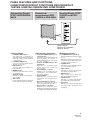 9
9
-
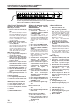 10
10
-
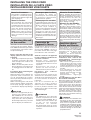 11
11
-
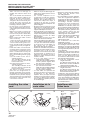 12
12
-
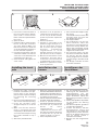 13
13
-
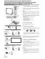 14
14
-
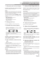 15
15
-
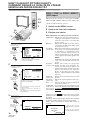 16
16
-
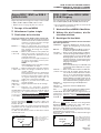 17
17
-
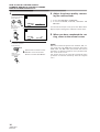 18
18
-
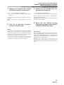 19
19
-
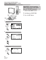 20
20
-
 21
21
-
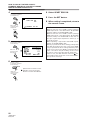 22
22
-
 23
23
-
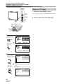 24
24
-
 25
25
-
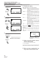 26
26
-
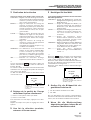 27
27
-
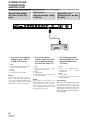 28
28
-
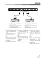 29
29
-
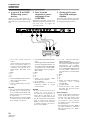 30
30
-
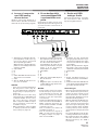 31
31
-
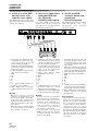 32
32
-
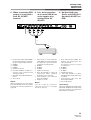 33
33
-
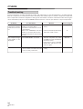 34
34
-
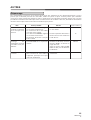 35
35
-
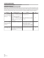 36
36
-
 37
37
-
 38
38
-
 39
39
-
 40
40
-
 41
41
-
 42
42
-
 43
43
-
 44
44
-
 45
45
-
 46
46
-
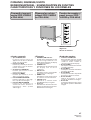 47
47
-
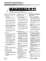 48
48
-
 49
49
-
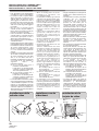 50
50
-
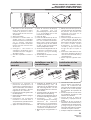 51
51
-
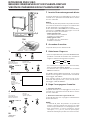 52
52
-
 53
53
-
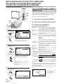 54
54
-
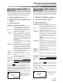 55
55
-
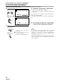 56
56
-
 57
57
-
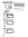 58
58
-
 59
59
-
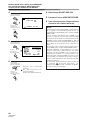 60
60
-
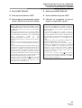 61
61
-
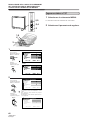 62
62
-
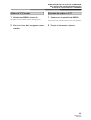 63
63
-
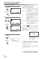 64
64
-
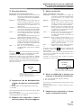 65
65
-
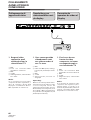 66
66
-
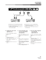 67
67
-
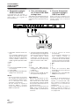 68
68
-
 69
69
-
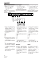 70
70
-
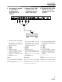 71
71
-
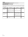 72
72
-
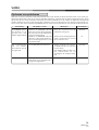 73
73
-
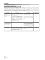 74
74
-
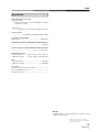 75
75
-
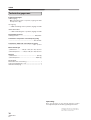 76
76
-
 77
77
-
 78
78
-
 79
79
-
 80
80


Pioneer PDA-4004 El manual del propietario
- Categoría
- Televisores de plasma
- Tipo
- El manual del propietario
en otros idiomas
- français: Pioneer PDA-4004 Le manuel du propriétaire
- italiano: Pioneer PDA-4004 Manuale del proprietario
- English: Pioneer PDA-4004 Owner's manual
- Deutsch: Pioneer PDA-4004 Bedienungsanleitung
- Nederlands: Pioneer PDA-4004 de handleiding