
Hyperchill
(50Hz)
(Precision control)
ICE015
ICE022
ICE029
ICE039
ICE046
ICE057
DATE: 25.02.2016 - Rev. 25
CODE: 398H271673
IT Manuale d’uso
EN User Manual
ES Manual de uso
DE Benutzer Handbuch


Italiano
1/8
Hyperchill-Precision Control ICE015-057
1 Sicurezza
1.1 Importanza del manuale
• Conservarlo per tutta la vita della macchina.
• Leggerlo prima di qualsiasi operazione.
• E’ suscettibile di modi che: per una informazione aggiornata con-
sultare la versione a bordo macchina
1.2 Segnali di avvertimento
!
Istruzione per evitare pericoli a persone.
Y
Istruzione da eseguire per evitare danni all’apparecchio.
Z
E’ richiesta la presenza di tecnico esperto e autorizzato.
,
Sono presenti simboli il cui signi cato è nel paragrafo 7.
1.3 Indicazioni di sicurezza
! Ogni unità è munita di sezionatore elettrico per intervenire in
condizioni di sicurezza. Usare sempre tale dispositivo per eliminare i
pericoli durante la manutenzione.
! Il manuale è rivolto all’utente nale solo per operazioni eseguibili
a pannelli chiusi: operazioni che ne richiedono l’apertura con attrezzi
devono essere eseguite da personale esperto e quali cato.
Y Non superare i limiti di progetto riportati nella targa dati.
! Y È compito dell’utilizzatore evitare carichi diversi dalla
pressione statica interna. Qualora sussista il rischio di azioni sismiche
l’unità va adeguatamente protetta.
Impiegare l’unità esclusivamente per uso professionale e per lo scopo
per cui è stata progettata.
E’ compito dell’utilizzatore analizzare tutti gli aspetti dell’applicazione
in cui il prodotto è installato, seguire tutti gli standards industriali di
sicurezza applicabili e tutte le prescrizioni inerenti il prodotto contenu-
te nel manuale d’uso ed in qualsiasi documentazione prodotta e fornita
con l’unità.
La manomissione o sostituzione di qualsiasi componente da parte di
personale non autorizzato e/o l’uso improprio dell’unità esonerano il
costruttore da qualsiasi responsabilità e provocano l’invalidità della
garanzia.
Si declina ogni responsabilità presente e futura per danni a persone,
cose e alla stessa unità, derivanti da negligenza degli operatori, dal
mancato rispetto di tutte le istruzioni riportate nel presente manuale,
dalla mancata applicazione delle normative vigenti relative alla sicurez-
za dell’impianto.
Il costruttore non si assume la responsabilità per eventuali danni dovu-
ti ad alterazioni e/o modi che dell’imballo.
E’ responsabilità dell’utilizzatore assicurarsi che le speci che fornite per
la selezione dell’ unità o di suoi componenti e/o opzioni siano esaustive
ai ni di un uso corretto o ragionevolmente prevedibile dell’unità stessa
o dei componenti.
ATTENZIONE: Il costruttore si riserva il diritto di modi care le
informazioni contenute nel presente manuale senza alcun preavviso.
Ai ni di una completa ed aggiornata informazione si raccomanda
all’utente di consultare il manuale a bordo unità.
1.4 Rischi residui
L’installazione, l’avviamento, lo spegnimento, la manutenzione della
macchina devono essere tassativamente eseguiti in accordo con quanto
riportato nella documentazione tecnica del prodotto e comunque in
modo che non venga generata alcuna situazione di rischio.
I rischi che non è stato possibile eliminare in fase di progettazione sono
riportati nella tabella seguente.
Parte
considerata
Rischio
residuo
Modalità Precauzioni
batteria di
scambio termico
piccole ferite
da taglio
contatto evitare il contatto, usare
guanti protettivi
griglia
ventilatore e
ventilatore
lesioni inserimento di oggetti
appuntiti attraverso la
griglia mentre il venti-
latore sta funzionando
non in lare oggetti di
alcun tipo dentro la griglia
dei ventilatori e non
appoggiare oggetti sopra
le griglie
interno unità:
compressore
e tubo di
mandata
ustioni contatto evitare il contatto, usare
guanti protettivi
interno unità:
parti metal-
liche e cavi
elettrici
intossicazioni,
folgorazione,
ustioni gravi
difetto di isolamento
cavi alimentazione
a monte del quadro
elettrico dell’unità.
Parti metalliche in
tensione
protezione elettrica ade-
guata della linea alimen-
tazione. Massima cura nel
fare il collegamento a terra
delle parti metalliche
esterno unità:
zona circostan-
te unità
intossicazioni,
ustioni gravi
incendio a causa corto
circuito o surriscal-
damento della linea
alimentazione a monte
del quadro elettrico
dell’unità
sezione dei cavi e sistema
di protezione della linea
alimentazione elettrica
conformi alle norme
vigenti
7 Appendice
7.1 Legenda
7.2 Diagramma di installazione
7.3 Dati tecnici
7.4 Dimensioni ingombro
7.5 Lista ricambi
7.6 Circuito frigorifero
7.7 Schema elettrico
Indice
1 Sicurezza 1
1.1 Importanza del manuale ....................................................................... 1
1.2 Segnali di avvertimento ......................................................................... 1
1.3 Indicazioni di sicurezza ......................................................................... 1
1.4 Rischi residui ......................................................................................... 1
2 Introduzione 2
2.1 Trasporto ................................................................................................. 2
2.2 Movimentazione .................................................................................... 2
2.3 Ispezione ................................................................................................. 2
2.4 Immagazzinaggio ................................................................................... 2
3 Installazione 2
3.1 Spazio operativo ..................................................................................... 2
3.2 Versioni ................................................................................................... 2
3.3 Circuito idraulico ................................................................................... 2
3.4 Circuito elettrico .................................................................................... 3
3.5 Versione centrifuga (C) .........................................................................3
3.6 Versione ad acqua (W) .......................................................................... 3
4 Controllo 4
4.1 Pannello di controllo ............................................................................. 4
4.2 Avviamento ............................................................................................. 4
4.3 Fermata .................................................................................................... 4
4.4 De nizione parametri ........................................................................... 4
4.5 Gestione parametri ................................................................................ 5
4.6 Gestione allarmi ..................................................................................... 5
4.7 Riavvio automatico ................................................................................ 5
5 Manutenzione 6
5.1 Avvertenze generali................................................................................ 6
5.2 Manutenzione preventiva ..................................................................... 6
5.3 Refrigerante ............................................................................................ 6
5.4 Smantellamento ...................................................................................... 6
6 Ricerca guasti 7

Italiano
2/8
2 Introduzione
I refrigeratori d’acqua sono unità monoblocco per la produzione di
acqua refrigerata in circuito chiuso. I motori di compressore, pompa
e ventilatore, sono dotati di una protezione termica che li protegge da
eventuali surriscaldamenti.
2.1 Trasporto
L’unità imballata deve rimanere:
a) In posizione verticale;
b) Protetta da agenti atmosferici;
c) Protetta da urti.
2.2 Movimentazione
Usare carrello elevatore a forca adeguato al peso da sollevare, evitando
urti di qualsiasi tipo.
2.3 Ispezione
a) In fabbrica tutte le unità sono assemblate, cablate, caricate con
refrigerante ed olio e collaudate;
b) ricevuta la macchina controllarne lo stato: contestare subito alla
compagnia di trasporto eventuali danni;
c) disimballare l’unità il più vicino possibile al luogo dell’installazione.
2.4 Immagazzinaggio
a) Mantenere l’unità imballata in luogo pulito e protetto da umidità e
intemperie;
b) Non sovrapporre le unità;
c) Seguire le istruzioni riportate sull’imballo.
3 Installazione
Y Per una installazione ottimale rispettare le indicazioni riportate
nei paragra 7.2, 7.3 e 7.7.
Y Per una corretta applicazione dei termini di garanzia, seguire le
istruzioni del report di avviamento, compilarlo e restituirlo alla ditta
venditrice.
! Liquidi da ra reddare
I liquidi da ra reddare devono essere compatibili con i materiali
utilizzati.
Esempi di liquidi usati sono acqua o miscele di acqua e glicole etileni-
co o propilenico.
I liquidi da ra reddare non devono essere in ammabili.
Se i liquidi da ra reddare contengono sostanze pericolose (come ad
esempio il glicole etilenico/propilenico) l’eventuale liquido fuoriu-
scito da una zona di perdita deve essere raccolto perchè dannoso per
l’ambiente. In caso di svuotamento del circuito idraulico, attenersi alle
normative vigenti e non disperdere il contenuto nell’ambiente.
3.1 Spazio operativo
Lasciare uno spazio di 1,5 metri attorno all’unità.
Lasciare almeno 2 metri di spazio sopra il refrigeratore nei modelli ad
espulsione verticale dell’aria di condensazione.
3.2 Versioni
Versione ad aria
Ventilatori assiali (A)
Non creare situazioni di ricircolo dell’aria di ra reddamento. Non
ostruire le griglie di ventilazione. Per le versioni con ventilatori assiali è
sconsigliata la canalizzazione dell’aria esausta.
Ventilatori centrifughi (C)
Garantire sempre una contropressione minima sull amandata dei ven-
tilatori canalizzando le singole uscite d’aria calda.
Versione ad acqua (W)
Se l’acqua al condensatore è in circuito aperto, installare ltro a rete su
ingresso acqua di condensazione.
Per particolari acque di ra reddamento (deionizzata, demineralizzata,
distillata) imateriali standard previsti per il condensatore potrebbero
non essere adatti. In questi casi si prega di contattare il costruttore.
3.3 Circuito idraulico
3.3.1 Controlli e collegamento
Y Prima di collegare il refrigeratore e riempire il circuito, assicurarsi
che le tubazioni siano pulite. In caso contrario e ettuare un lavaggio
accurato.
Y Se il circuito idraulico è di tipo chiuso, in pressione, è consigliabile
installare una valvola di sicurezza tarata a 6 bar.
Y Si consiglia di installare sempre dei ltri a rete sulle tubazioni di
ingresso e uscita acqua.
Y Nel caso in cui il circuito idraulico sia intercettato da valvole auto-
matiche, proteggere la pompa con sistemi anti colpo d’ariete.
Y Nel caso il circuito venga svuotato per fermate prolungate si con-
siglia di aggiungere del uido lubri cante sulla girante della pompa per
evitarne il blocco al successivo avviamento. In caso di blocco girante
procedere con sblocco manuale.
Rimuovere il coperchio posteriore della pompa e girare delicatamente
la ventola in plastica. Se l’albero risultasse ancora bloccato, rimuovere
la ventola e agire direttamente sull’albero. Una volta sbloccata la giran-
te, riposizionare ventola e coperchio.
Controlli preliminari
1) Controllare che le eventuali valvole di intercettazione del circuito
idraulico siano aperte.
2) Se il circuito idraulico è di tipo chiuso, controllare che sia stato in-
stallato un vaso d’espansione di capacità adeguata. Vedere paragrafo
3.3.3.
Collegamento
1) Collegare il refrigeratore d’acqua alle tubazioni di ingresso e uscita,
utilizzando gli appositi attacchi posizionati nella parte posteriore
dell’unità.
Si consiglia l’utilizzo di giunti essibili per togliere rigidità al sistema.
2) Riempire il circuito idraulico utilizzando l’apposito attacco di cari-
ca posizionato nella parte posteriore del refrigeratore (
).
3) Il serbatoio è dotato di un’apposita valvola di s ato che dovrà essere
azionata manualmente al momento del riempimento. A tal propo-
sito, se il circuito idraulico presenta dei punti ad altezza maggiore,
installare una valvola di s ato in tali punti.
4) Si consiglia di dotare le tubazioni di ingresso ed uscita di un val-
vole, in modo da poter escludere la macchina dal circuito in caso di
manutenzione e di regolazione per la pompa.
5) Se il chiller lavora con vasca aperta, la pompa deve essere installata
in aspirazione alla vasca e in mandata al chiller.
Controlli successivi
1) Controllare che il serbatoio ed il circuito siano completamente
riempiti d’acqua e correttamente s atati dall’aria.
2) Il circuito idraulico dev’essere sempre riempito. A tal ne si può
provvedere ad un controllo e rabbocco periodico, oppure si può
dotare l’impianto di un kit di riempimento automatico.
3.3.2 Acqua e glicole etilenico
Se installato all’aperto, o comunque in ambiente chiuso non riscaldato,
c’è la possibilità che, nei periodi di fermata dell’impianto in corri-
spondenza ai mesi più freddi dell’anno, l’acqua all’interno del circuito
ghiacci.
Per evitare questo pericolo si può:
a) Dotare il refrigeratore di adeguate protezioni antigelo, fornite dal
costruttore come opzionali;
b) Scaricare l’impianto tramite l’apposita valvola di scarico, in caso di
fermate prolungate;
c) Aggiungere un’adeguata quantità di antigelo all’acqua di circolazio-
ne (vedi tabella).
A volte la temperatura dell’acqua in uscita è tale da richiedere che essa
venga miscelata con glicole etilenico, per evitare formazioni di ghiac-
cio, nelle percentuali sotto riportate.
Temperatura acqua
in uscita [°C]
Glicole etilenico
(% vol.)
Temperatura
ambiente
45-2
210-5
015-7
-2 20 -10
-4 25 -12
-6 30 -15
Hyperchill-Precision Control ICE015-057

Italiano
3/8
Hyperchill-Precision Control ICE015-057
3.3.3 Vaso d’espansione
Per evitare che gli aumenti o diminuzioni di volume del uido con-
seguenti ad una variazione sensibile della sua temperatura possano
danneggiare la macchina o il circuito, è consigliabile installare un vaso
d’espansione di capacità adeguata.
Il vaso d’espansione va installato in aspirazione alla pompa sull’attacco
posteriore del serbatoio.
Per un calcolo del volume del vaso d’espansione da applicare ad un
circuito chiuso si può utilizzare la formula seguente:
V=2 x Vtot x (Pt min - P t max)
dove
Vtot= vol. totale del circuito (in litri)
P t min/max = peso speci co alla minima/massima temperatura rag-
giungibile dall’acqua [kg/dm3].
I valori di peso speci co in funzione della temperatura e della percen-
tuale di glicole, sono riportati in tabella.
%
glicole
Temperatura [°C]
-100 1020304050
0% 1.0024 1.0008 0.9988 0.9964 0.9936 0.9905 0.9869
10% 1.0177 1.0155 1.0130 1.0101 1.0067 1.0030 0.9989
20% 1.0330 1.0303 1.0272 1.0237 1.0199 1.0156 1.0110
30% 1.0483 1.0450 1.0414 1.0374 1.0330 1.0282 1.0230
! Attenzione: In fase di riempimento fare riferimento ai dati di
carica anche del vaso di espansione.
3.4 Circuito elettrico
3.4.1 Controlli e collegamenti
! Prima di e ettuare qualsiasi operazione su parti elettriche assicu-
rarsi che non vi sia tensione.
Tutte le connessioni elettriche devono essere conformi alle prescrizioni
locali del luogo di installazione.
Controlli iniziali
1) La tensione e la frequenza di rete devono corrispondere ai valori
stampigliati sulla targhetta dati del refrigeratore. La tensione di
alimentazione non deve, neppure per brevi periodi, essere fuori dalla
tolleranza riportata sullo schema elettrico che, salvo diverse indica-
zioni, è pari +/- 10% per la tensione; +/- 1% sulla frequenza.
2) La tensione deve essere simmetrica (valori e caci delle tensioni ed
angoli di fase fra fasi consecutive uguali fra loro). Il massimo squili-
brio ammesso fra le tensioni è pari al 2%
Collegamento
1) L’alimentazione elettrica dei refrigeratori viene e ettuata con cavo a
4 li , 3 poli +terra, senza neutro. Per la sezione vedere paragrafo 7.3.
2) Passare il cavo attraverso il pressacavo posto sul pannello posteriore
della macchina e collegare fase e neutro ai morsetti del sezionatore
generale (QS), la terra va collegata all’apposito morsetto di terra
(PE).
3) Assicurare all’origine del cavo di alimentazione una protezione
contro i contatti diretti pari ad almeno IP2Xo IPXXB.
4)Installare , sulla linea di alimentazione elettrica del refrigeratore,
un interruttore automatico con di erenziale (RCCB - IDn = 0.3A),
della portata massima indicata nello schema elettrico di riferimento,
con potere di interruzione adeguato alla corrente di corto circuito
esistente nella zona d’installazione della macchina.
La corrente nominale “In” di tale magnetotermico deve essere uguale
a FLA e la curva di intervento di tipo D.
5) Valore massimo dell’impedenza di rete = 0.274 ohm.
Controlli successivi
Assicurarsi che la macchina e le apparecchiature ausiliarie siano state
messe a terra e protette contro cortocircuiti e/o sovraccarichi.
! Una volta che l’unità è stata collegata e l’interruttore generale a
monte è stato chiuso (dando così tensione alla macchina), il voltaggio
nel circuito elettrico raggiunge valori pericolosi. Massima precauzione!
3.4.2 Allarme generale
Tutti i refrigeratori sono provvisti della segnalazione allarme macchina
(vedere schema elettrico), costituita da un contatto libero in scambio
riportato in morsettiera: ciò permette di allacciare un allarme centraliz-
zato esterno, acustico, visivo o inserito in logiche es. PLC.
3.4.3 ON/OFF remoto
Tutti i refrigeratori hanno la possibilità di avere un comando di avvia-
mento e fermata remoto.
Per il collegamento del contatto ON-OFF remoto vedere lo schema
elettrico.
3.5 Versione centrifuga (C)
Utilizzata quando si vuole poter canalizzare l’aria calda proveniente
dalla condensazione.
I ventilatori centrifughi hanno la capacità di imprimere all’aria una
pressione statica utile tale da vincere le perdite di carico derivanti da
una canalizzazione.
Attenzione: le unità dotate di ventilatori centrifughi non possono esse-
re installate in aria libera, senza canalizzazione. I ventilatori centrifughi
, per funzionare correttamente, necessitano di una contropressione
minima tale da impedire un ”fuori giri” del motore elettrico ed una sua
conseguente rottura.
Regole di canalizzazione
1) Ogni ventilatore dev’essere canalizzato singolarmente: i ventilatori
devono avere la possibilità di lavorare in maniera indipendente.
2) Le canalizzazioni devono avere super cie di passaggio dell’aria pari
a quelle dei ventilatori montati sull’unità.
3.6 Versione ad acqua (W)
I chiller in versione con condensazione ad acqua, necessitano di un
circuito idraulico che porti l’acqua fredda al condensatore.
Il chiller in versione ad acqua è dotato di una valvola pressostatica, in
entrata al condensatore, la cui funzione è quella di regolare la portata
d’acqua in modo da ottenere sempre una condensazione ottimale.
Controlli preliminari
Se l’alimentazione di acqua al condensatore viene realizzata tramite
circuito chiuso, e ettuare tutti i controlli preliminari elencati per il
circuito idraulico principale (paragrafo 3.3.1).
Collegamento
1) Si consigliadidotare il circuito acqua di condensazione di valvole di
intercettazione, in modo da poter escludere la macchina in caso di
manutenzione.
2) Collegare le tubazioni dimandata/ritorno acqua agli appositi attac-
chi posti sul retro dell’unità.
3) Se l’acqua di condensazione è ” a perdere”, si consiglia di dotare il
circuito di un ltro in ingresso al condensatore, in modo da limitare
il rischio di sporcamento delle super ci.
4) Se il circuito è di tipo chiuso, veri care che sia ben riempito d’acqua
e correttamente s atato dall’aria.

Italiano
4/8
4 Controllo
4.1 Pannello di controllo
Fig.1
LIV Low water level
PI
enter
Low pressure
Pump alarm
High pressure
on
HP
TP
LP
off
C
F
I
O
Power supply
PS
4L3L0P
L5
L6
L7
L8
L9
L1
P6
P1
P2
P5
P3
P4
L2
Compr essor alarm
alarms
WATER
OUT
WATER
IN
LIV Low water level
PI
enter
Low pressure
Pump alarm
High pressure
on
HP
TP
LP
off
C
F
Power supply
PS
4L3L
L5
L6
L7
L8
L9
L1
P6
P1
P2
P5
P3
P4
L2
Compressor alarm
alarms
P0 Interruttore sezionatore.
P1 Pulsante ON : attiva il controllore.
P2 Pulsante OFF : disattiva il controllore.
P3 Pulsante SU : per aumentare il valore dei parametri modi cabili.
P4 Pulsante GIU’ : per diminuire il valore dei parametri modi cabili.
P5 Pulsante enter: per confermare i parametri modi cati.
P6 Pulsante alarms: per resettare gli allarmi a reset manuale.
LED ACCESO LAMPEGGIANTE
L1: giallo
Scheda è alimentata
L2: verde
Scheda è in On Con scheda alimentata ed in OFF: è
attiva una resistenza antigelo.
Con scheda alimentata ed in On: un
compressore è in chiamata ma sta
aspettando un ritardo
L3: rosso
Unità di misura °C
L4: rosso
Unità di misura °F
L5: rosso
Allarme alta pressione
Modalità programmazione Loop USER
o FACTORY.
L6: rosso
Allarme bassa pressione
L7: rosso
Allarme termico pompa
L8: rosso
Allarme basso livello acqua
serbatoio
L9: rosso
Allarme protezione
compressore
4.2 Avviamento
• Dare tensione alla macchina mettendo in on il sezionatore
generale QS[P0].
• Mettere in on il refrigeratore nel modo seguente: mettere in On il
tasto On/O [P1].
• Impostare sul controllore la temperatura desiderata.
Monitore di fase
Se al l’ avviamento compare a display l’allarme “PI1”, l’utente deve
veri care di avere eseguito correttamente il cablaggio dei morsetti di
ingresso all’interruttore sezionatore.
4.2.1 Regolazioni al primo avviamento
a) Il chiller è regolato per una temperatura di defoult di 12°C con un
di erenziale di 3°C, se si vuole e ettuare una nuova regolazione
vedere paragrafo 4.5.
b) Veri care il corretto funzionamento della pompa utilizzando il
manometro (leggere P1 e P0) e i valori limite di pressione (Pmax e
Pmin) riportati sulla targa dati della pompa.
P1 = pressione con pompa ON
P0 = pressione con pompa OFF
Pmin < (P1-P0) < Pmax
- Esempio n°1.
Condizioni:
circuito chiuso a pressione P0 di 2 bar
dati targa pompa: Pmin 1bar/ Pmax 3bar
regolare l’uscita valvola per una pressione di 3bar< P1< 5Bar
- Esempio n°2.
Condizioni:
circuito aperto a pressione P0 di 0 bar
dati targa pompa: Pmin 1bar/ Pmax 3bar
regolare l’uscita valvola per una pressione di 1bar< P1< 3Bar
c) Veri care il corretto funzionamento della pompa anche in condi-
zioni di regime.
Ver i care inoltre che l’amperaggio della pompa sia entro i limiti di
targa.
d) Spegnere il chiller e procedere con il rabbocco del circuito idraulico
con la temperatura di “SET”.
e) Controllare che la temperatura dell’acqua “trattata” non scenda sotto
i 5°C e la temperatura ambiente in cui opera il circuito idraulico non
scenda sotto 5°C. In caso contrario aggiungere all’acqua l’opportuna
quantità di glicole, come spiegato nel paragrafo 3.3.2
4.3 Fermata
Quando non è più richiesto il funzionamento del refrigeratore mettere
in o il refrigeratore come segue: premere il tasto P2.
Non mettere in o il sezionatore generale QS [P0] in modo da garanti-
re l’alimentazione di eventuali resistenze antigelo presenti nel refrige-
ratore.
4.4 De nizione parametri
Generalità
Esistono due livelli di protezione per i parametri:
a) Diretto (D): con accesso immediato, Modi cabili;
b) Sotto password (U): con accesso con password; Parametri da non
modi care.
4.4.1 Parametri macchina
PARAMETRO CODICE TIPO DEFAULT
Unità di misura
C-F
U
0
Indirizzo unità
Adr
U
1
Abilitazione on / o remoto
(paragrafo 4.4.1.1).
rE
U
0
Gestione relè allarme
(paragrafo 4.4.1.2)
rAL
U
0
Con gurazione uscita digitale 2
Ud2
U
0
Con gurazione uscita digitale 3
Ud3
U
0
Gestione allarme termico pompa
AtP
U
1
Contaore macchina
HUL
U
-
Contaore macchina
HUH
U
-
Soglia allarme contaore macchina
tHU
U
0
4.4.1.1 Modalità On / O remoto
0
On/O remoto disabilitato.
1
On/O remoto abilitato assieme al On/O da locale
2
Solo On/O remoto , On/O da locale disabilitato
Hyperchill-Precision Control ICE015-057

Italiano
5/8
Hyperchill-Precision Control ICE015-057
4.4.1.2 Gestione relè allarme
0
Relè normalmente diseccitato, viene eccitato in presenza di
un allarme.
1
Relè normalmente eccitato (anche con controllo in OFF),
viene diseccitato in presenza di un allarme.
2
Relè normalmente eccitato (solo con in ON), viene disecci-
tato in presenza di un allarme o con controllo in OFF.
4.4.2 Termostatazione
PARAMETRO CODICE TIPO DEFAULT
Set point termostatazione
SEt
D
20.0
Limite inferiore set point
LI5
U
5.0
4.4.3 Parametri sonda B1
PARAMETRO CODICE TIPO DEFAULT
Con gurazione alta temperatura
cHAI
U
0
Allarme alta temperatura
HAI
D
60.0
Allarme bassa temperatura
LAI
D
-20.0
Calibrazione sonda
CAI
U
0.0
Di erenziale riarmo allarme
bassa temperatura
dbI
U
1.0
4.4.4 Parametri sonda B2
PARAMETRO CODICE TIPO DEFAULT
Con gurazione alta temperatura
cHA2
U
0
Allarme alta temperatura
HA2
U
60.0
Allarme bassa temperatura
LA2
U
3.0
Calibrazione sonda
CA2
U
0.0
Presenza sonda B2
Ab2
U
1.0
4.4.5 Parametri sonda B3
PARAMETRO CODICE TIPO DEFAULT
Allarme alta temperatura
HA3
U
60.0
Allarme bassa temperatura
LA3
U
-20.0
Calibrazione sonda
CA3
U
0.0
4.4.6 Parametri compressore
PARAMETRO CODICE TIPO DEFAULT
Contaore compressore 1.
HI
D
-
Soglia allarme contaore compres-
sore
tHI
U
0
4.4.7 Parametri pompa
PARAMETRO CODICE TIPO DEFAULT
Ritardo spegnimento pompa
dP5
U
5
Ritardo accensione pompa
dPA
U
5
4.4.8 Parametri resistenza antigelo
PARAMETRO CODICE TIPO DEFAULT
Set point regolazione (B1)
SEA
U
7.0
Di erenziale termostatazione (B1)
dIA
U
1.0
Modalità funzionamento resisten-
za antigelo (paragrafo 4.4.8.1)
FUA
U
0
Modalità attivazione resistenza
antigelo (paragrafo 4.4.8.2)
AbrA
U
2
Set point attivazione (B3)
ArA
U
5.0
4.4.8.1 Modalità funzionamento resistenza antigelo FUA
0
Termostatazione resistenza da B1 con set SEA, attivazione
pompa da B3 (sonda ambiente) con setARA, resistenza ttiva-
ta se pompa attivata.
1
Termostatazione resistenza + attivazione pompa da B3 (son-
da ambiente) con set ARA.
2
Termostatazione resistenza da B1 con set SEA, attivazione
pompa da B3 (sonda ambiente) con setARA, resistenza e
pompa con attivazione separata.
4.4.8.2 Modalità attivazione resistenza antigelo AbrA
0
Attivazione solo con scheda in On
1
Attivazione anche con scheda in O
2
Attivazione anche con scheda in O . Durante il funziona-
mento della resistenza c’è l’attivazione della pompa.
4.5 Gestione parametri
4.5.1 Regolazione temperatura (vedere g.1)
1. Dare tensione alla macchina mettendo in on il sezionatore generale
QS, ed attendere la visualizzazione della temperatura.
2. Premere contemporaneamente i tasti “P3” e “P5” per entrare nei
parametri tipo “dIrE” (D) .
3. Premere il tasto “P4” per selezionare il parametro “SEt” , premere
il tasto “P5” per conferma.
4. Modi care il valore usando i tasti “P3”e “ P4” su e giù e premere il
tasto “P5” per confermare e uscire.
6. Premere “P3” per tornare su “dIrE” .
7. Premere “P5” per uscire.
4.5.2 Visualizzazione sonde temperatura B1,B2...
La sonda B1 è la sonda di “SET” della macchina.
1. Avviare la macchina.
2. Premere il tasto “P4” e visualizzare la temperatura della sonda
successiva .
3. Premere il tasto “P5” per visualizzare quale sonda “b01” ..“b02”..
state guardando.
Si consiglia di lasciare sempre in visione la sonda di temperatura “B1”
di set.
4.6 Gestione allarmi
4.6.1 Allarmi da ingressi digitali
ID CODICE LED DESCRIZIONE RESET
ID1
HPI
L5 Allarme alta pressione da pressostato M
ID2
LPI
L6
Allarme bassa pressione da
pressostato
M
ID3
tP
L7 Allarme termico pompa M
ID4
LL
L8
Allarme basso livello acqua serbatoio
/ Mancanza usso acqua
A
ID6
PII
L9
Allarme protezione compressore/
Inversione di fase
M
4.6.2 Allarmi da ingressi analogici
AI CODICE DESCRIZIONE RESET
B1
HAI
Allarme alta temperatura uscita acqua
serbatoio
Avviso
LAI
Allarme bassa temperatura uscita acqua
serbatoio
A
StI
Sonda aperta o Sonda in corto M
B2
HA2
Allarme alta temperatura uscita acqua
evaporatore
Avviso
LA2
Allarme bassa temperatura uscita acqua
evaporatore
A
St2
Sonda aperta o Sonda in corto M
B3
HA3
Avviso alta temperatura ambiente Avviso
LA3
Avviso bassa temperatura ambiente Avviso
St3
Sonda aperta o Sonda in corto M
4.7 Riavvio automatico
Se c’è una mancanza di alimentazione elettrica, al ritorno di questa il
refrigeratore conserva lo stato di On o O .

Italiano
6/8
5 Manutenzione
a) La macchina è progettata e costruita per garantire un funzionamen-
to continuativo; la durata dei suoi componenti è però direttamente
legata alla manutenzione eseguita.
b) In caso di richiesta di assistenza o ricambi, identi care la macchina
(modello e numero di serie) leggendo la targhetta di identi cazione
esterna all’unità.
c) I circuiti contenenti 3 kg o più di uido refrigerante sono controllati
per individuare perdite almeno una volta all’anno.
I circuiti contenenti 30 kg o più di uido refrigerante sono control-
lati per individuare perdite almeno una volta ogni sei mesi ((UE) N.
517/2014 art. 4.3.a, 4.3.b).
d) Per le macchine contenenti 3 kg o più di uido refrigerante, l’ope-
ratore deve tenere un registro in cui si riportano la quantità e il tipo
di refrigerante utilizzato, le quantità eventualmente aggiunte e quelle
recuperate durante le operazioni di manutenzione, di riparazione e
di smaltimento de nitivo ((UE) N. 517/2014 art. 6). Esempio di tale
registro è scaricabile dal sito: www.polewr.com.
5.1 Avvertenze generali
! Prima di qualsiasi manutenzione veri care che il refrigeratore
non sia più alimentato.
Y Utilizzare sempre ricambi originali del costruttore: pena l’esonero
del costruttore da qualsiasi responsabilità sul malfunzionamento della
macchina.
Y In caso di perdita di refrigerante contattare personale esperto ed
autorizzato.
Y La valvola Schrader è da utilizzare solo in caso di anomalo funzio-
namento della macchina: in caso contrario i danni provocati da errata
carica di refrigerante non verranno riconosciuti in garanzia.
5.2 Manutenzione preventiva
Per garantire nel tempo la massima e cienza ed a dabilità del chiller
eseguire:
a)
Z ogni 4 mesi - pulizia alette condensatore e veri ca assorbi-
mento elettrico compressore entro valori di targa;
b)
Z annualmente - versione W: in caso di incrostazioni
interne al condensatore immettere e far circolare apposito
liquido detergente.
b)
Z ogni 3 anni - installazione kit manutenzione ogni 3 anni.
Sono disponibili (vedere paragrafo 7.5):
a) kit manutenzione ogni 3 anni;
b)kit service;
1. kit compressore;
2. kit ventilatore;
3. kit pompa P3;
4. kit valvola di espansine
c) ricambi sciolti.
5.3 Refrigerante
Z Operazione di carica: eventuali danni provocati da errata carica
eseguita da personale non autorizzato non verranno riconosciuti in
garanzia.
Y L’apparecchiatura contiene gas uorurati a e etto serra.
Il uido frigorigeno R407C a temperatura e pressione normale è un gas
incolore appartenente al SAFETY GROUP A1 - EN378 ( uido gruppo
2 secondo direttiva PED 97/23/EC);
GWP (Global Warming Potential) = 1774.
! In caso di fuga di refrigerante aerare il locale.
5.4 Smantellamento
Il uido frigorigeno e l’olio lubri cante contenuto nel circuito dovran-
no essere recuperati in conformità alle locali normative ambientali
vigenti.
Il recupero del uido refrigerante è e ettuato prima della distruzione
de nitiva dell’apparecchiatura ((UE) N. 517/2014 art.8).
%
RICICLAGGIO
SMALTIMENTO
carpenteria acciaio/resine epossidi-poliestere
serbatoio alluminio/rame/acciaio
tubazioni/collettori rame/alluminio/acciaio al carbonio
isolamento tubazioni gomma nitrilica (NBR)
compressore acciaio/rame/alluminio/olio
condensatore acciaio/rame/alluminio
pompa acciaio/ghisa/ottone
ventilatore alluminio
refrigerante R407C (HFC)
valvole ottone/rame
cavi elettrici rame/PVC
Hyperchill-Precision Control ICE015-057

Italiano
7/8
Hyperchill-Precision Control ICE015-057
6 Ricerca guasti
GUASTO
CAUSA
RIMEDIO
LA TEMPERATURA
DELL’ACQUA IN USCITA
E’ SUPERIORE AL VALORE
IMPOSTATO
IL COMPRESSORE SI
FERMA PER INTERVENTO
DEL PRESSOSTATO DI ALTA
PRESSIONE
ASPIRAZIONE
COMPRESSORE,
LINEA LIQUIDO
BRINATI
IL COMPRESSORE
FUNZIONA
LUNGAMENTE,
E’ RUMOROSO
PORTATA ACQUA
ECCESSIVA, CARICO
TERMICO ELEVATO
DIMINUIRE LA PORTATA
DEL FLUIDO DA RAFFRED-
DARE
TEMPERATURA
AMBIENTE
ELEVATA
RIPORTARE LA
TEMPERATURA
AMBIENTE SOTTO IL
VALORE LIMITE
DICHIARATO
PRESSOSTATO
ROTTO O
STARATO
SOSTITUIRE IL
PRESSOSTATO
FILTRO
REFRIGERANTE
INTASATO
SOSTITUIRE
IL FILTRO
ALETTE DEL
CONDENSATORE
SPORCHE
PULIRE LE
ALETTE DEL
CONDENSATORE
SUPERFICIE DEL
CONDENSATORE
OSTRUITA
LIBERARE LA
SUPERFICIE
FRONTALE DEL
CONDENSATORE
PORTATA
ACQUA
INSUFFICIENTE
AUMENTARE
LA PORTATA DEL
FLUIDO DA RAF-
FREDDARE
COMPONENTI
COMPRESSORE
DETERIORATI
RIPARARE O
SOSTITUIRE
COMPRESSORE
PERDITE NEL
CIRCUITO,
IMPIANTO SCARICO
VERIFICARE LA
PRESENZA DI
PERDITE, ELIMINARLE,
CARICARE IL
CIRCUITO
FILTRO
REFRIGERANTE
INTASATO
SOSTITUIRE
IL FILTRO
si
no
si
si si
si si
si
si
si
si
no
no
no
no
IL COMPRESSORE SI
FERMA PER INTERVENTO
DEL PRESSOSTATO DI BASSA
PRESSIONE
no
VENTILATORE
GIRA ROVESCIO
no
INVERTIRE
LE FASI
BULBO
TERMOSTATO
SCARICO
no
VA LV O L A
TERMOSTATICA
STARATA
no
SOSTITUIRE
LA VALVOLA
RITARARE
LA VALVOLA
si
si
no
no
si

Italiano
8/8
Hyperchill-Precision Control ICE015-057

English
1/8
Hyperchill-Precision Control ICE015-057
1 Safety
1.1 Importance of the manual
• Keep it for the entire life of the machine.
• Read it before any operation.
• It is subject to changes: for updated information see the version on
the machine.
1.2 Warning signals
!
Instruction for avoiding danger to persons.
Y
Instruction for avoiding damage to the equipment.
Z
e presence of a skilled or authorized technician is re-
quired.
,
ere are symbols whose meaning is given in the para. 7.
1.3 Safety instructions
! Every unit is equipped with an electric disconnecting switch for
operating in safe conditions. Always use this device in order to elimi-
nate risks maintenance.
! e manual is intended for the end-user, only for operations per-
formable with closed panels: operations requiring opening with tools
must be carried out by skilled and quali ed personnel.
Y Do not exceed the design limits given on the dataplate.
! Y It is the user’s responsibility to avoid loads di erent from
the internal static pressure. e unit must be appropriately protected
whenever risks of seismic phenomena exist.
Only use the unit for professional work and for its intended purpose.
e user is responsible for analysing the application aspects for product
installation, and following all the applicable industrial and safety stand-
ards and regulations contained in the product instruction manual or
other documentation supplied with the unit.
Tampering or replacement of any parts by unauthorised personnel
and/or improper machine use exonerate the manufacturer from all
responsibility and invalidate the warranty.
e manufacturer declines and present or future liability for damage
to persons, things and the machine, due to negligence of the operators,
non-compliance with all the instructions given in this manual, and
non-application of current regulations regarding safety of the system.
e manufacturer declines any liability for damage due to alterations
and/or changes to the packing.
It is the responsibility of the user to ensure that the speci cations
provided for the selection of the unit or components and/or options are
fully comprehensive for the correct or foreseeable use of the machine
itself or its components.
IMPORTANT: e manufacturer reserves the right to modify this
manual at any time.
For the most comprehensive and updated information, the user is
advised to consult the manual supplied with the unit.
1.4 Residual risks
e installation, start up, stopping and maintenance of the machine
must be performed in accordance with the information and instruc-
tions given in the technical documentation supplied and always in such
a way to avoid the creation of a hazardous situation.
e risks that it has not been possible to eliminate in the design stage
are listed in the following table.
part
a ected
residual
risk
manner of
exposure
precautions
heat exchanger
coil
small cuts contact avoid contact, wear pro-
tective gloves
fan grille and
fan
lesions insertion of pointed
objects through the
grille while the fan is
in operation
ndo not poke objects of
any type through the fan
grille or place any objects
on the grille
inside the unit:
compressor
and discharge
pipe
burns contact avoid contact, wear pro-
tective gloves
inside the unit:
metal parts
and electrical
wires
intoxication,
electrical
shock, serious
burn
defects in the insula-
tion of the power
supply lines upstream
of the electrical panel;
live metal parts
adequate electrical protec-
tion of the power supply
line; ensure metal parts
are properly connected
to earth
outside the
unit:
area surround-
ing the unit
intoxication,
serious burns
iire due to short circuit
or overheating of the
supply line upstream
of the unit’s electrical
panel
sensure conductor cross-
sectional areas and the
supply line protection sys-
tem conform to applicable
regulations
Index
1 Safety 1
1.1 Importance of the manual .................................................................... 1
1.2 Warning signals ...................................................................................... 1
1.3 Safety instructions ..................................................................................1
1.4 Residual risks .......................................................................................... 1
2 Introduction 2
2.1 Transport ................................................................................................. 2
2.2 Handling .................................................................................................. 2
2.3 Inspection................................................................................................ 2
2.4 Storage ..................................................................................................... 2
3 Installation 2
3.1 Operating space ...................................................................................... 2
3.2 Versions ................................................................................................... 2
3.3 Water circuit ...........................................................................................2
3.4 Electrical circuit ..................................................................................... 3
3.5 Centrifugal version (C) ......................................................................... 3
3.6 Water-cooled version (W) .................................................................... 3
4 Control 4
4.1 Control panel .......................................................................................... 4
4.2 Starting the chiller .................................................................................. 4
4.3 Stopping the chiller ................................................................................ 4
4.4 Parameter settings .................................................................................. 4
4.5 Parameter management ........................................................................ 5
4.6 Alarms management.............................................................................. 5
4.7 Automatic restart ................................................................................... 5
5 Maintenance 6
5.1 General instructions ..............................................................................6
5.2 Preventive maintenance ........................................................................ 6
5.3 Refrigerant .............................................................................................. 6
5.4 Dismantling ............................................................................................ 6
6 Troubleshooting 7
7 Appendix
7.1 Legend
7.2 Installation diagram
7.3 Technical data
7.4 Dimensions
7.5 Spare parts
7.6 Circuit diagram
7.7 Wiring diagram

English
2/8
Hyperchill-Precision Control ICE015-057
2 Introduction
ese water coolers are monoblock units for the production of cooled
water in a closed circuit.
e fan, pump and compressor motors are equipped with a thermal
protector that protects them against possible overheating.
2.1 Transport
e packed unit must remain:
a) Upright;
b) Protected against atmospheric agents;
c) Protected against impacts.
2.2 Handling
Use a fork-li truck suitable for the weight to be li ed, avoiding any
type of impact
2.3 Inspection
a) All the units are assembled, wired, charged with refrigerant and oil
and tested in the factory;
b) On receiving the machine check its condition: immediately notify
the transport company in case of any damage;
c) Unpack the unit as close as possible to the place of installation.
2.4 Storage
a) Keep the unit packed in a clean place protected from damp and
bad weather.
b) Do not stack the units;
c) Follow the instructions given on the package.
3 Installation
YFor correct installation, follow the instructions given in par.7.2, 7.3
and 7.7.
Y For the correct application of the warranty terms, follow the
instructions given in the start-up report, ll it in and send it back to
Seller
! Liquids to be chilled
e liquids to be chilled must be compatible with the materials used.
Examples of liquids used are water or mixtures of water and ethylene
or propylene glycols.
e liquids to be chilled must not be ammable.
If the liquids to be chilled contain hazardous substances (e.g. ethylene/
propylene glycol), any liquid discharged from a leakage area must be
collected, because it is harmful to the environment. When draining
the hydraulic circuit, comply with the current regulations and do not
disperse the contents in the environment.
3.1 Operating space
Leave a space of 1.5 m around the unit.
Leave a space of at least 2 metres above the refrigerator in models with
vertical emission of condensation air.
3.2 Versions
Air-cooled version
Axial fans (A)
Do not create cooling air recirculation situations.
Do not obstruct the ventilation grilles.
e ducting of extracted air is not recommended for versions with
axial fans.
Centrifugal version (C)
Always ensure a minimum counterpressure on the delivery of
fans, ducting the individual hot air outlets.
Water- cooled version (W)
If the water to the condenser is in open circuit, install a mesh lter on
the condensation water inlet.
Please note that for special cooling water types such as demineral-
ized, deionized or distilled it is necessary to contact the manufacturer
to verify which kind of condenser should be used since the standard
material may not be suitable.
3.3 Water circuit
3.3.1 Checks and connection
Y Before connecting the chiller and lling the water circuit, check
that all the pipes are clean. If not, wash them out thoroughly.
Y If the plumbing circuit is of the closed type, under pressure it is
advisable to install a safety valve set to 6 bar.
Y Always install mesh lters on the water inlet and outlet pipelines.
Y If the hydraulic circuit is intercepted by automatic valves, protect
the pump with an anti-hammering system.
Y If the hydraulic circuit is emptied for shut-down periods we
recommend that you add lubricating uid to the pump’s impeller to
avoid the risk of blockage when it is re-started. In case the impeller is
blocked then you should unblock it manually.
Remove the rear cover of the pump and carefully turn the plastic fan.
If the impeller is stuck then remove the fan and turn the impeller sha
directly. A er un-blocking the impeller re-assemble the fan and cover.
Preliminary checks
1) Check that any shut-o valves in the water circuit are open.
2) In the case of a closed water circuit, check that an expansion tank
of suitable capacity has been installed. See paragraph 3.3.3.
Connection
1) Connect the water cooler to the inlet and outlet piping, using the
special connections located on the back of the unit.
We recommend the use of exible unions to reduce system rigidity.
2) Fill the water circuit using the tting provided on the rear of the
chiller (
).
3) e tank is equipped with a breather valve that should be operated
manually when lling the tank. Also, if the hydraulic circuit has high
points, install a vent valve at the highest points.
4) We recommend that taps are installed on the inlet and outlet pipes,
so that the unit can be excluded for maintenance when necessary.
5) If the chiller works with an open tank, the pump must be installed
on intake to the tank and on delivery to the chiller.
Subsequent checks
1) Check that the tank and the circuit are completely full of water and
that all the air has been expelled from the system.
2) e water circuit must always be kept full. For this reason, carry
out periodic checks and top the circuit up if necessary, or install an
automatic lling kit.
3.3.2 Water and ethylene glycol
If installed outdoors or in an unheated indoor area, it is possible that
the water in the circuit may freeze if the system is not in operation dur-
ing the coldest times of the year.
To avoid this hazard:
a) Equip the chiller with suitable antifreeze protection devices, avail-
able from the manufacturer as optional accessories;
b) Drain the system via the drain valve if the chiller is to remain idle
for a prolonged period;
c) Add an appropriate quantity of antifreeze to the water in circula-
tion (see table).
Sometimes the temperature of the outlet water is so low as to require
the addition of ethylene glycol in the following percentages.
Outlet water
temperature [°C]
Ethylene glycol
(% vol.)
Ambient
temperature
45-2
210-5
015-7
-2 20 -10
-4 25 -12
-6 30 -15
3.3.3 Expansion tank
To avoid the possibility of an increase or decrease in the volume of the
uid due to a signi cant change in its temperature causing damage to
the machine or the water circuit, we recommend installing an expan-
sion tank of suitable capacity.
e expansion tank must be installed on intake to the pump on the
rear connection of the tank.

English
3/8
Hyperchill-Precision Control ICE015-057
e minimum volume of an expansion tank to be installed on a closed
circuit can be calculated using the following formula:
V=2 x Vtot x (Pt min - P t max)
where
Vtot= vol. circuit total (in litres)
P t min/max= speci c weight at the minimum/maximum temperature
reached by the water [kg/dm3].
e speci c weight values at di erent temperatures for glycol percent-
age values are given in the table.
%
glicol
Temperature [°C]
-100 1020304050
0% 1.0024 1.0008 0.9988 0.9964 0.9936 0.9905 0.9869
10% 1.0177 1.0155 1.0130 1.0101 1.0067 1.0030 0.9989
20% 1.0330 1.0303 1.0272 1.0237 1.0199 1.0156 1.0110
30% 1.0483 1.0450 1.0414 1.0374 1.0330 1.0282 1.0230
! Caution: When lling the system, take into account the capac-
ity of the expansion vessel as well.
3.4 Electrical circuit
3.4.1 Checks and connections
! Before carrying out any operation on the electrical system, make
sure that the appliance is disconnected from the electrical power sup-
ply.
All electrical connections must comply with the applicable regulations
in force in the country of installation.
Initial checks
1) e power supply voltage and frequency must correspond to the
values stamped on the chiller nameplate. e power supply charac-
teristics must not deviate, even for brief periods, from the tolerance
limits indicated on the electrical diagram , which are +/- 10% for the
voltage; +/- 1% for the frequency.
2) e power supply must be symmetrical (the e ective voltages and
the phase angles of consecutive phases must be equal). e maxi-
mum permissible voltage imbalance is 2%.
Connection
1) e electrical power supply must be connected to the chiller using a
4-wire cable, comprising 3 phase conductors and an earth conductor,
with no neutral. For minimum cable section, see par. 7.3.
2) Pass the cable through the cable entry on the rear panel of the ma-
chine and connect the phase and neutral to the terminals of the main
isolator switch (QS); connect the earth wire to the earth terminal
(PE).
3) Ensure that supply cable has at its source protection against direct
contact of at least IP2X or IPXXB.
4) On the supply line to the chiller, install a residual-current circuit
breaker with a trip rating of (RCCB - IDn = 0.3A), with the current
rating indicated in the reference electrical diagram, and with a short
circuit current rating appropriate to the short circuit fault current
existing in the machine installation area.
e nominal current In of the magnetic circuit breaker must be
equal to the FLA with an intervention curve type D.
5) Max. grid impedance value = 0.274 ohm.
Subsequent checks
Check that the machine and the auxiliary equipment are earthed and
protected against short circuit and/or overload.
! Once the unit has been connected and the upstream main switch
closed (thereby connecting the power supply to the machine), the
voltage in the electrical circuit will reach dangerous levels. Maximum
caution is required!
3.4.2 General alarm
All the chillers are equipped with an alarm signalling system (see
electrical diagram), comprised of a switching free contact in a terminal
block: this may be used for the connection of an external audible or
visual alarm, or used to provide an input signal for a logic control
system such as a PLC.
3.4.3 ON/OFF remoto
All the chillers can be connected to a remote ON/OFF control.
See the electrical diagram for the connection of the remote ON-OFF
contact.
3.5 Centrifugal version (C)
Used when ducting of the hot air coming from cooling is required.
In fact, the centrifugal fans are able to give the air a useful static pres-
sure that overcomes the pressure losses due to ducting.
Important: Units equipped with centrifugal fans cannot be installed
in open air without ducting. To work correctly, the centrifugal fans re-
quire a minimum counterpressure preventing the electric motor from
”over-revving” and its consequent breaking.
Rules for ducting
1) Each fan must be individually ducted: the fans must be able to work
independently.
2) e ducting must have air ow are as equal to those of the fans
installed on the unit.
3.6 Water-cooled version (W)
In the water-cooled version, the chillers require a water circuit that
takes the cold water to condenser.
e water version chiller is equipped with a pressure regulating valve
at the condenser inlet, whose function is to regulate the water ow in
order to always obtain optimum condensation.
Preliminary checks
If the water supply to the condenser is by means of a closed circuit,
perform all the preliminary checks listed for the main water
circuit (para. 3.3.1).
Connection
1) It is advisable to equip the cooling water circuit with shuto valves,
enabling the machine to be cut out in case of maintenance.
2) Connect the water delivery/return pipes to the special connections
located on the back of the unit.
3) If the cooling water is “expendable” it is advisable to equip the
circuit with a lter at the condenser inlet, in order to reduce the risk
of the surfaces becoming dirtied.
4) If the circuit is of the closed type, make sure it is lled with water
and the air properly vented.

English
4/8
Hyperchill-Precision Control ICE015-057
4 Control
4.1 Control panel
Fig.1
LIV Low water level
PI
enter
Low pressure
Pump alarm
High pressure
on
HP
TP
LP
off
C
F
I
O
Power supply
PS
4L3L0P
L5
L6
L7
L8
L9
L1
P6
P1
P2
P5
P3
P4
L2
Compr essor alarm
alarms
WATER
OUT
WATER
IN
LIV Low water level
PI
enter
Low pressure
Pump alarm
High pressure
on
HP
TP
LP
off
C
F
Power supply
PS
4L3L
L5
L6
L7
L8
L9
L1
P6
P1
P2
P5
P3
P4
L2
Compressor alarm
alarms
P0 Isolator switch.
P1 On key: activates the controller.
P2 O key: deactivates the controller.
P3 UP key: used to increase the value of a modi able parameter.
P4 DOWN key: used to decrease the value of a modi able parameter
P5 Enter key: used to con rm modi cations to parameters.
P6 Alarms key: used to reset all manual reset alarms.
LED ON FLASHING
L1: yellow
Controller is receiving
power
L2: green
Controller is On With the controller receiving power
and ‘O ’: an antifreeze heater is on.
With the controller receiving power
and ‘On’: compressor called for, but
wating for a delay time to elapse.
L3: red
°C unit of measurement
L4: red
°F unit of measurement
L5: red
High pressure alarm
USER Loop or FACTORY program-
ming mode
L6: red
Low pressure alarm
L7: red
Pump temperature alarm
L8: red
Low water level alarm
L9: red
Compressor protection
alarm
4.2 Starting the chiller
• Connect the power supply to the machine by turning the main
isolator switch QS [P0] to ON.
• Turn the chiller ‘ON’ by pressing the key [P1].
• Set the desired temperature on the controller.
Phases Monitor
If appears on display the alarm “PI1 “, during the start up, the user
must verify the wiring of the input terminals of the disconnecting
switch.
4.2.1 Adjustments at commissioning
a) e chiller is set for operation at a default temperature of 12 °C with
a di erential of 3 °C; to adopt a new setting, see heading 4.5.
b) Verify correct operation of the pump, using the pressure gauge
(read P1 and P0) and checking the pressure limit values (Pmax and
Pmin) indicated on the pump data plate.
P1 = pressure with pump ON
P0 = pressure with pump OFF
Pmin < (P1-P0) < Pmax
- Example n°1.
Conditions:
closed circuit, pressure P0 = 2 bar
pump data plate values: Pmin 1 bar/ Pmax 3 bar
adjust the valve outlet to give a pressure of 3 bar < P1< 5 bar
- Example n°2.
Conditions:
open circuit, pressure P0 = 0 bar
pump data plate values: Pmin 1 bar/ Pmax 3 bar
adjust the valve outlet to give a pressure of 1 bar < P1 < 3 bar
c) Verify correct operation of the pump similarly under normal run-
ning conditions.
Check also that the amperage of the pump is within the limits indi-
cated on the data plate.
d) Switch o the chiller and proceed to top up the hydraulic circuit at
the “SET” temperature.
e) Check that the temperature of the “treated” water does not fall
below 5 °C and that the ambient temperature in which the hydraulic
circuit operates does not fall below 5 °C. If the temperature is too
low, add the appropriate quantity of glycol, as explained under head-
ing 3.3.2
4.3 Stopping the chiller
When chiller operation is no longer required, turn the chiller o as fol-
lows: press key [P2] to switch the controller ‘O ’.
Do not turn o the main switch QS [P0] to ensure that any antifreeze
protection devices will still receive electrical power.
4.4 Parameter settings
General
ere are two levels of protection for parameters:
a) Direct (D): with immediate access, User-changeable;
b) Password protected (U): password required for access; Factory-set
parameters.
4.4.1 Chiller parameters
PARAMETER CODE TYPE DEFAULT
Unit of measurement
C-F
U
0
Unit address
Adr
U
1
Remote on / o enabling
(see para. 4.4.1.1).
rE
U
0
Alarm relay management (see
para. 4.4.1.2)
rAL
U
0
Digital output 2 con guration
Ud2
U
0
Digital output 3 con guration
Ud3
U
0
Pump thermal alarm management
AtP
U
1
Chiller hour counter
HUL
U
-
Chiller hour counter
HUH
U
-
Chiller hour counter alarm
threshold
tHU
U
0
4.4.1.1 Remote On / O mode
0
Remote On/O disabled
1
Remote On/O enabled together with local On/O
2
Remote On/O only, local On/O disabled

English
5/8
Hyperchill-Precision Control ICE015-057
4.4.1.2 Alarm relay management
0
Relay normally deactivated, excited by an alarm.
1
Relay normally excited (also with control OFF), deactivated
by an alarm.
2
Relay normally excited (only with control ON), deactivated
by an alarm or with control OFF.
4.4.2 Temperature control
PARAMETER CODE TYPE DEFAULT
Temperature control set point
SEt
D
20.0
Set point lower limit
LI5
U
5.0
4.4.3 B1 sensor parameters
PARAMETER CODE TYPE DEFAULT
High temperature con guration
cHAI
U
0
High temperature alarm
HAI
D
60.0
Low temperature alarm
LAI
D
-20.0
Sensor calibration
CAI
U
0.0
Low temperature alarm reset
di erential
dbI
U
1.0
4.4.4 B2 sensor parameters
PARAMETER CODE TYPE DEFAULT
High temperature con guration
cHA2
U
0
High temperature alarm
HA2
U
60.0
Low temperature alarm
LA2
U
3.0
Sensor calibration
CA2
U
0.0
B2 sensor presence
Ab2
U
1.0
4.4.5 B3 sensors parameters
PARAMETER CODE TYPE DEFAULT
High temperature alarm
HA3
U
60.0
Low temperature alarm
LA3
U
-20.0
Sensor calibration
CA3
U
0.0
4.4.6 Compressor parameters
PARAMETER CODE TYPE DEFAULT
Compressor operation hour counter
HI
D
-
Compressor hour counter threshold
tHI
U
0
4.4.7 Pump parameters
PARAMETER CODE TYPE DEFAULT
Pump stop delay
dP5
U
5
Pump start delay
dPA
U
5
4.4.8 Antifreeze heater parameters
PARAMETER CODE TYPE DEFAULT
Set point adjustment (B1)
SEA
U
7.0
Temperature control di erential
(B1)
dIA
U
1.0
Antifreeze heater operating mode
(see para. 4.4.8.1)
FUA
U
0
Antifreeze heater activation mode
(see para. 4.4.8.2)
AbrA
U
2
Activation set point (B3)
ArA
U
5.0
4.4.8.1 FUA antifreeze heater operating mode
0
Heating element thermostatting by B1 with SEAsetting,
pump activation by B3 (ambient sensor) with ARA setting,
heating element activated if pump is activated.
1
Heating element thermostatting + pump activation by B3
(ambient sensor) with ARA setting.
2
Heating element thermostatting by B1 with SEAsetting,
pump activation by B3 (ambient sensor) with ARA setting,
heating element and pump with separate activation.
4.4.8.2 AbrA antifreeze heater activation mode
0
Activation only when controller is ‘On’
1
Activation also when controller is ‘O ’
2
Activation also when controller is ‘O ’. During heater op-
eration the pump is activated.
4.5 Parameter management
4.5.1 Temperature setting (see g.1)
1. 1. Turn the main swicth (QS) to “ON” and wait for the temperature
visualization.
2. Press buttons “P3” and “P5” together, to enter into “dIrE” (D)
parameters.
3. Press button “P4” to select “SEt” parameter, press the button
“P5” to con rm.
4. Change the value, using the up and down arrow buttons “P3” and
“P4”, then press button “P5” to con rm.
6. Press the button “P3” to return on “dIrE” parameter.
7. Press the button “P5” to exit.
4.5.2 Visualization sensors B1,B2...
“B1” is the “set” sensor of the macchine.
1. Start the chiller.
2. Press the button “P4” to visualize the temperature of the next sen-
sor.
3. Press the button “P5” to visualize the sensors “b01” ..“b02”....
It is recommended to leave on the display the B1 “set” sensor.
4.6 Alarms management
4.6.1 Digital input alarms
ID CODE LED DESCRIPTION RESET
ID1
HPI
L5
High pressure alarm from pressure
switch
M
ID2
LPI
L6
Low pressure alarm from pressure
switch
M
ID3
tP
L7 Pump thermal cutout alarm M
ID4
LL
L8
Water tank low water level alarm / No
water ow
A
ID6
PII
L9
Compressor protection alarm /
Phases monitor
M
4.6.2 Allarmi da ingressi analogici
AI CODE DESCRIPTION RESET
B1
HAI
Tank water outlet water high tempera-
ture alarm
Warning
LAI
Tank water outlet water low tempera-
ture alarm
A
StI
Sensor open circuit or short circuit M
B2
HA2
Evaporator water outlet water high
temperature alarm
Warning
LA2
Evporator water outlet water low tem-
perature alarm
A
St2
Sensor open circuit or short circuit M
B3
HA3
High ambient temperature warning Warning
LA3
Low ambient temperature warning Warning
St3
Sensor open circuit or short circuit M
4.7 Automatic restart
In the event of a power failure, when power is restored the chiller will
assume theOn-O statusheld at themoment the power was lost.

English
6/8
Hyperchill-Precision Control ICE015-057
5 Maintenance
a) e machine is designed and built to guarantee continuous opera-
tion; however, the life of its components depends on the mainte-
nance performed.
b) When requesting assistance or spare parts, identify the machine
(model and serial number) by reading the dataplate located on the
unit.
c) Circuits containing 3 kg or more of refrigerant uid are checked to
identify leaks at least once a year.
Circuits containing 30 kg or more of refrigerant uid are checked to
identify leaks at least once every six months. ((EU) No. 517/2014 art.
4.3.a, 4.3.b).
d) For machines containing 3 kg or more of refrigerant uid, the op-
erator must keep a record stating the quantity and type of refrigerant
used, an quantities added and that recovered during maintenance
operations, repairs and nal disposal ((EU) No. 517/2014 art. 6). An
example of this record sheet can be downloaded from the site: www.
polewr.com.
5.1 General instructions
! Before performing any maintenance, make sure the power to the
refrigerator is disconnected.
Y Always use the Manufacturer’s original spare parts: otherwise the
Manufacturer is relieved of all liability regarding machine malfunction-
ing.
Y In case of refrigerant leakage, contact quali ed and authorized
personnel.
Y e Schrader valve must only be used in case of machine malfunc-
tion: otherwise any damage caused by incorrect refrigerant charging
will not be covered by the warranty.
5.2 Preventive maintenance
To guarantee lasting maximum chiller e ciency and reliability, carry
out:
a)
Z every 4 months - clean the condenser ns and make sure com-
pressor electrical absorption is within the dataplate values;
b)
Z yearly - W version: in case of encrustations inside the con-
denser, introduce and circulate a speci c detergent liquid.
b)
Z Every 3 years - installation of kit for maintenance every 3
years. (par.7.5)
a) kit for maintenance every 3 years;
b)service kit;
1. compressor kit;
2. fan kit;
3. P3 pump kit;
4. expansion valve kit
c) individual spare parts.
5.3 Refrigerant
Z Charging: any damage caused by incorrect charging carried out by
unauthorized personnel will not be covered by the warranty.
Y e equipment contains uorinated greenhouse gases.
At normal temperature and pressure, the R407C refrigerant is a col-
ourless gas classi ed in SAFETY GROUP A1 - EN378 (group 2 uid
according to Directive PED 97/23/EC);
GWP (Global Warming Potential) = 1774.
! In case of refrigerant leakage, air the room.
5.4 Dismantling
e refrigerant and the lubricating oil contained in the circuit must be
recovered in conformity with current local environmental regulations.
e refrigerant uid is recovered before nal scrapping of the equip-
ment ((EU) No. 517/2014 art.8).
%
Recycling
Disposal
frame and panels steel/epoxy resin polyester
tank aluminium/copper/steel
pipes/collectors copper/aluminium/carbon steel
pipe insulation NBR rubber
compressor steel/copper/aluminium/oil
condensator steel/copper/aluminium
pump steel/cast iron/brass
fan aluminium
refrigerant R407C (HFC)
valve brass/copper
electrical cable copper/PVC

English
7/8
Hyperchill-Precision Control ICE015-057
6 Troubleshooting
FAULT
CAUSE
REMEDY
THE OUTLET WATER
TEMPERATURE EXCEEDS
THE SET VALUE
COMPRESSOR STOPS
DUE TO OPERATION OF
THE HIGH PRESSURE
SWITCH
COMPRESSOR SUCTION,
LIQUID LINE FROSTED
THE COMPRESSOR RUNS
FOR LONG PERIODS, IS
NOISY
EXCESSIVE
WATER FLOW,
HIGH THERMAL
LOAD
REDUCE THE FLOW
RATE OF THEWATER TO BE
COOLED
HIGH
AMBIENT
TEMPERATURE
RETURN THE
AMBIENT
TEMPERATURE TO
BELOW THE
SPECIFIED LIMIT
PRESSURE SWITCH BROKEN OR
INCORRECTLY CALIBRATED
REPLACE
PRESSURE
SWITCH
REFRIGE---
RANT FILTER
CLOGGED
RENEW
THE FILTER
CONDENSER
FINS
DIRTY
CLEAN THE
FINS OF THE
CONDENSER
CONDENSER
SURFACES
CLOGGED
CLEAR THE FRONT
SURFACE OF THE CON-
DENSER
INSUFFICIENT
WATER FLOW
INCREASE
THE FLOW
RATE OF THE
FLUID TO BE
COOLED
COMPRESSOR
COMPONENTS
DETERIORATED
REPAIR OR
REPLACE
COMPRESSOR
LEAKS IN CIRCUIT,
SYSTEM DISCHARGED
CHECK FOR
LEAKS, REPAIR,
CHARGE THE
CIRCUIT
REFRIGERANT
FILTER
CLOGGED
RENEW
THE FILTER
yes
no
yes
yes yes
yes
yes
yes
yes
yes
yes
no
no
no
no
COMPRESSOR STOPS DUE
TO OPERATION OF THE
LOW PRESSURE SWITCH
no
FAN ROTATES
BACKWARDS
no
SWAP OVER
THE
PHASEWIRES
THERMOSTATIC
BULB
DISCHARGED
no
THERMOSTATIC
VA LV E
INCORRECTLY
CALIBRATED
no
RENEW
THE VALVE
RECALIBRA-
TE
THE VALVE
yes
yes
no
no
yes

English
8/8
Hyperchill-Precision Control ICE015-057

Español
1/8
Hyperchill-Precision Control ICE015-057
1 Seguridad
1.1 Importancia del manual
• Consérvelo durante toda la vida útil del equipo.
• Léalo antes de realizar cualquier operación.
• Puede sufrir modi caciones: para una información actualizada,
consulte la versión instalada en el equipo.
1.2 Señales de advertencia
!
Instrucción para evitar peligros personales
Y
Instrucción para evitar que se dañe el equipo.
Z
Se requiere la intervención de un técnico experto y autori-
zado.
,
El signi cado de los símbolos utilizados se indica en el
apartado 7.
1.3 Instrucciones de seguridad
! Todas las unidades están provistas de un seccionador eléctrico
que permite trabajar en condiciones de seguridad. Utilícelo siempre
durante el mantenimiento.
! El manual está destinado al usuario nal y sólo para las operacio-
nes que pueden realizarse con los paneles cerrados. Las operaciones
que requieren la apertura con herramientas deben ser efectuadas por
personal experto y cali cado
Y No supere los límites de proyecto que se indican en la placa de
características.
! Y El usuario debe evitar cargas distintas de la presión estática
interna. En caso de riesgo de fenómenos sísmicos, es necesario prote-
ger adecuadamente la unidad.
La unidad debe utilizarse exclusivamente para uso profesional y con el
objeto para el cual ha sido diseñada.
El usuario debe analizar todos los aspectos de la aplicación en que
el producto se ha instalado, seguir todas las normas industriales de
seguridad aplicables y todas las prescripciones relativas al producto
descritas en el manual de uso y en la documentación redactada que se
adjunta a la unidad.
La alteración o sustitución de cualquier componente por parte del per-
sonal no autorizado, así como el uso inadecuado de la unidad eximen
de toda responsabilidad al fabricante y provocan la anulación de la
garantía.
El fabricante declina toda responsabilidad presente o futura por daños
personales o materiales derivados de negligencia del personal, incum-
plimiento de las instrucciones dadas en este manual o inobservancia de
las normativas vigentes sobre la seguridad de la instalación.
El fabricante no asume ninguna responsabilidad por daños debidos a
alteraciones y/o modi caciones del embalaje.
El usuario es responsable que las especi caciones suministradas para
seleccionar la unidad o sus componentes y/o opciones sean exhaustivas
para un uso correcto o razonablemente previsible de la misma unidad
o de los componentes.
ATENCIÓN: El fabricante se reserva el derecho de modi car sin
previo aviso la información de este manual. Para que la información
resulte completa, se recomienda al usuario consultar el manual a pie
de máquina.
1.4 Riesgos residuales
Las operaciones de instalación, puesta en marcha, apagado y man-
tenimiento del equipo deben realizarse de total conformidad con lo
indicado en la documentación técnica del equipo y de manera tal que
no se genere ninguna situación de riesgo.
Los riesgos que no han podido eliminarse con recursos técnicos de
diseño se indican en la tabla siguiente.
parte del
equipo
riesgo
residual
modo precauciones
batería de
intercambio
térmico
pequeñas
heridas
cortantes
contacto evitar el contacto, usar
guantes de protección
rejilla del
ventilador y
ventilador
lesiones introducción de
objetos puntiagudos
en la rejilla mientras
el ventilador está
funcionando
no introducir ni apoyar
ningún objeto en la rejilla
de los ventiladores
interior del
equipo:
compresor y
tubo de salida
quemaduras contacto evitar el contacto, usar
guantes de protección
interior del
equipo: partes
metálicas y ca-
bles eléctricos
intoxicación,
electrocución,
quemaduras
graves
defecto de aislamiento
de los cables de ali-
mentación que llegan
al cuadro eléctrico del
equipo; partes metáli-
cas en tensión
protección eléctrica
adecuada de la línea de
alimentación; conectar
cuidadosamente a tierra
las partes metálicas
exterior del
equipo: zona
circundante
intoxicación,
quemaduras
graves
incendio por corto-
circuito o sobrecalen-
tamiento de la línea
de alimentación del
cuadro eléctrico del
equipo
sección de los cables y
sistema de protección de
la línea de alimentación
eléctrica conformes a las
normas vigentes
7 Apéndice
7.1 Leyenda
7.2 Esquema de instalación
7.3 Datos técnicos
7.4 Dibujos de dimensiones
7.5 Lista de repuestos
7.6 Circuitos de refrigerante
7.7 Esquema eléctrico
Índice
1 Seguridad 1
1.1 Importancia del manual ........................................................................ 1
1.2 Señales de advertencia ........................................................................... 1
1.3 Instrucciones de seguridad ................................................................... 1
1.4 Riesgos residuales................................................................................... 1
2 Introducción 2
2.1 Transporte ............................................................................................... 2
2.2 Traslado ................................................................................................... 2
2.3 Inspección ............................................................................................... 2
2.4 Almacenaje.............................................................................................. 2
3 Instalación 2
3.1 Espacio operativo ................................................................................... 2
3.2 Versiones ................................................................................................. 2
3.3 Circuito hidráulico .................................................................................2
3.4 Circuito eléctrico .................................................................................... 3
3.5 Versión centrífuga (C) ........................................................................... 3
3.6 Versión por agua (W) ............................................................................ 3
4 Control 4
4.1 Panel de control ...................................................................................... 4
4.2 Puesta en marcha ................................................................................... 4
4.3 Parada ...................................................................................................... 4
4.4 De nición de los parámetros ............................................................... 4
4.5 Administración de parámetros ............................................................ 5
4.6 Administración de las alarmas ............................................................. 5
4.7 Reactivación automática ....................................................................... 6
5 Mantenimiento 6
5.1 Advertencias generales .......................................................................... 6
5.2 Mantenimiento preventivo ................................................................... 6
5.3 Refrigerante ............................................................................................ 6
5.4 Desguace ................................................................................................. 6
6 Solución de problemas 7

Español
2/8
Hyperchill-Precision Control ICE015-057
2 Introducción
Los refrigeradores de agua son unidades monobloque para la produc-
ción de agua refrigerada en circuito cerrado.ICE015-057ICE015-057
Los motores del compresor, de la bomba y del ventilador están dotados
de una protección térmica contra eventuales sobrecalentamientos.
2.1 Transporte
El equipo embalado debe mantenerse:
a) en posición vertical;
b) protegido de los agentes atmosféricos;
c) protegido de golpes.
2.2 Traslado
Utilice una carretilla elevadora con horquillas, adecuada para el peso
del equipo, y evite todo tipo de golpes.
2.3 Inspección
a) Todos los equipos salen de fábrica ensamblados, cableados, carga-
dos con refrigerante y aceite, y probados;
b) Controle el equipo a su llegada y noti que inmediatamente al
transportista si nota algún inconveniente;
c) Desembale el equipo lo más cerca posible del lugar de instalación.
2.4 Almacenaje
a) Conserve el equipo en un lugar limpio y protegido de la humedad
y la intemperie;
b) no apilar las unidades;
c) seguir las instrucciones presentes en el embalaje.
3 Instalación
Y
Para realizar correctamente la instalación, siga las instrucciones
dadas en los apartados 7.2, 7.3 y 7.7.
! Líquidos que pueden enfriarse
Sólo pueden enfriarse líquidos que sean compatibles con los materiales
empleados.
Algunos de los líquidos usados son agua o mezclas de agua y eti-
lenglicol o propilenglicol.
No se deben enfriar líquidos in amables.
Si los líquidos a refrigerar contienen sustancias peligrosas (como por
ejemplo glicol etilénico/propilénico), hay que recoger el líquido derra-
mado en una zona de fuga porque es perjudicial para el medio ambien-
te. En caso de vaciado del circuito hidráulico, hay que cumplir con las
normas vigentes y evitar la liberación del líquido al medio ambiente.
3.1 Espacio operativo
Deje un espacio libre de 1,5 m todo alrededor del equipo.
Dejar al menos 2 metros de espacio encima del refrigerador en los
modelos de expulsión vertical del aire de condensación.
3.2 Versiones
Versión por aire
Ventiladores axiales (A)
No cree situaciones que permitan la recirculación del aire de enfria-
miento. No obstruya las rejillas de ventilación.
En las versiones con ventiladores axiales, se desaconseja canalizar el
aire agotado.
Ventiladores centrífugos (C)
Garantizar siempre una contrapresión mínima en el envío de los venti-
ladores canalizando las salidas de aire caliente.
Versión por agua (W)
Si el agua del condensador está en circuito abierto, instalar un ltro de
malla en la entrada del agua de condensación.
Es posible que los materiales estándar previstos para el condensador
no sean adecuados para determinadas aguas de refrigeración (desioni-
zada, desmineralizada, destilada). En estos casos, se ruega ponerse en
contacto con el fabricante.
3.3 Circuito hidráulico
3.3.1 Controles y conexionado
Y Antes de conectar el enfriador y llenar el circuito, asegurarse de
que los tubos estén limpios. De lo contrario, lavarlos cuidadosamente.
Y Si el circuito hidráulico es de tipo cerrado, bajo presión, se acon-
seja instalar una válvula de seguridad calibrada a 6 bar.
Y Se recomienda instalar ltros de red en los tubos de entrada y
salida del agua.
Y Si el circuito hidráulico posee válvulas automáticas de corte,
proteger la bomba con sistemas contra golpe de ariete.
Y Si se vacía el circuito por paradas prolongadas, se recomienda
añadir aceite lubricante en el rodete de la bomba para evitar su bloqueo
en el arranque siguiente. En caso de bloqueo del rodete, desbloquéelo
manualmente.
Quite la tapa posterior de la bomba y gire suavemente el ventilador de
plástico. Si el eje siguiera bloqueado, quite el ventilador y actúe direc-
tamente en el eje. Una vez desbloqueado el rodete, vuelva a colocar el
ventilador y la tapa.
Controles preliminares
1) Cerciorarse de que las válvulas de corte del circuito hidráulico
estén abiertas.
2) Si el circuito hidráulico es cerrado, controlar que se haya instalado
un vaso de expansión de capacidad adecuada. Ver el apartado 3.3.3.
Conexionado
1) Conectar el refrigerador de agua a los conductos de entrada y
salida utilizando los correspondientes empalmes ubicados en la parte
trasera de la unidad.
Se aconseja utilizar conexiones exibles para quitar rigidez al siste-
ma.
2) Llenar el circuito hidráulico utilizando la conexión de carga situada
en la parte posterior del enfriador (
).
3) El depósito está provisto de un purgador de aire que debe accio-
narse manualmente a la hora del llenado. Si el circuito hidráulico
presenta puntos elevados, instalar una válvula de escape en ellos.
4) Se aconseja instalar válvulas de corte en la entrada y la salida del
equipo para poder excluirlo del circuito en caso de mantenimiento.
5) Si el enfriador funciona con cuba abierta, la bomba se debe instalar
en el tubo de admisión de la cuba y en el tubo de impulsión al enfria-
dor.
Controles sucesivos
1) Controlar que el depósito y el circuito estén completamente llenos
de agua y que se haya purgado todo el aire.
2) El circuito hidráulico debe mantenerse siempre lleno. Para ello se
debe controlar y rellenar periódicamente, o bien instalar un disposi-
tivo de llenado automático.
3.3.2 Agua y etilenglicol
ISi el equipo está instalado en el exterior, o en un local cubierto pero
sin calefacción, durante las paradas en los meses más fríos el agua que
está dentro del circuito se puede congelar.
Para evitarlo, es posible:
a) dotar al enfriador de adecuadas protecciones antihielo suministra-
das como opcionales por el fabricante;
b) descargar la instalación a través de la válvula correspondiente, en
caso de paradas prolongadas;
c) aañadir un anticongelante al agua de circulación (ver tabla).
A veces, la temperatura de salida del agua exige el uso de etilenglicol
para evitar la formación de hielo. Las proporciones adecuadas son:
Temperatura agua
de salida [°C]
Etilenglicol
(% vol.)
Temperatura
ambiente
45-2
210-5
015-7
-2 20 -10
-4 25 -12
-6 30 -15
3.3.3 Vaso de expansión
Para evitar que los aumentos o las disminuciones de volumen causados
por las variaciones de temperatura dañen el equipo o el circuito, es
conveniente instalar un vaso de expansión de capacidad adecuada.
El vaso de expansión se instala siempre en el lado de aspiración de la
bomba.

Español
3/8
Hyperchill-Precision Control ICE015-057
El volumen mínimo del vaso de expansión que se debe aplicar a un
circuito cerrado se calcula con la fórmula siguiente:
V = 2 x Vtot x (Pt mín. - P t máx.)
donde
Vtot= volumen total del circuito (en litros)
P t mín./máx. = peso especí co a la temperatura mínima/máxima que
puede alcanzar el agua [kg/dm3].
En la tabla siguiente se indican los pesos especí cos en función de la
temperatura y del porcentaje de glicol.
%
glicol
Temperature [°C]
-100 1020304050
0% 1.0024 1.0008 0.9988 0.9964 0.9936 0.9905 0.9869
10% 1.0177 1.0155 1.0130 1.0101 1.0067 1.0030 0.9989
20% 1.0330 1.0303 1.0272 1.0237 1.0199 1.0156 1.0110
30% 1.0483 1.0450 1.0414 1.0374 1.0330 1.0282 1.0230
! Atención: Durante el llenado, tomar como referencia los datos
de carga también del depósito de expansión.
3.4 Circuito eléctrico
3.4.1 Controles y conexionado
! Antes de realizar cualquier operación en las partes eléctricas,
cerciorarse de que no circule corriente.
Todas las conexiones eléctricas deben realizarse de conformidad con
las disposiciones vigentes en el lugar de instalación.
Controles iniciales
1) La tensión y la frecuencia de red deben tener los valores indicados
en la chapa de datos del enfriador. La tensión de alimentación no
debe salirse en ningún momento de las tolerancias indicadas en el
esquema eléctrico, las cuales, salvo indicación diversa, son +/- 10%
para la tensión y +/- 1% para la frecuencia.
2) La tensión debe ser simétrica (valores e caces de las tensiones y
ángulos de fase entre fases consecutivas iguales entre sí). El desequi-
librio máximo admitido entre las tensiones es del 2%.
Conexionado
1) La alimentación eléctrica de los enfriadores se realiza con un cable
de cuatro conductores (tres polos más tierra) sin neutro. Para la
sección mínima del cable, vea el apartado 7.3.
2) Pasar el cable por el sujetacables situado en el panel posterior del
equipo, conectar la fase y el neutro a los bornes del seccionador
general (QS) y la tierra al borne correspondiente (PE).
3) Instalar en el origen del cable de alimentación una protección con-
tra contactos directos no inferior a IP2X o IPXXB.
4) En la línea de alimentación eléctrica del enfriador debe haber un
interruptor automático con diferencial de (RCCB - IDn = 0.3A), la
capacidad máxima indicada en el esquema eléctrico de referencia y
un poder de corte adecuado a la corriente de cortocircuito existente
en el lugar de instalación.
La corriente nominal “In” de dicho magnetotérmico debe ser igual a
FLA y la curva di intervención de tipo D.
5) Valor máximo de la impedancia de red = 0,274 ohm.
Controles sucesivos
Comprobar que el equipo y los dispositivos auxiliares estén conectados
a tierra y protegidos contra cortocircuitos y sobrecargas.
! Una vez conectado el equipo, cuando se cierra el interruptor
general de alimentación para energizarlo, la tensión en el circuito eléc-
trico alcanza valores peligrosos. ¡Se recomienda la máxima precaución!
3.4.2 Alarma general
Todos los enfriadores están dotados de indicación de alarma (véase el
esquema eléctrico). La regleta tiene un contacto de conmutación libre
donde puede conectarse una alarma centralizada exterior de tipo acús-
tico, visual o incluida en un sistema lógico (por ejemplo un PLC).
3.4.3 Encendido y apagado a distancia
Todos los enfriadores pueden dotarse de un mando de arranque y
parada a distancia.
Para la conexión del contacto ON-OFF a distancia, véase el esquema
eléctrico.
3.5 Versión centrífuga (C)
Se utiliza cuando se desea canalizar el aire caliente que proviene de la
condensación.
Los ventiladores centrífugos tienen la capacidad de dar al aire una
presión estática útil para superar las pérdidas de carga derivadas de la
canalización.
Atención: las unidades conventiladores centrífugos no se pueden
instalar al aire libre sin canalización. Para que los ventiladores
centrífugos funcionen correctamente, necesitan una contrapresión
mínima que impida que el motor eléctrico vaya fuera de revoluciones
y se rompa.
Reglas de canalización
1) Todos los ventiladores se deben canalizar de forma individual:
tienen que tener la posibilidad de trabajar de forma independiente.
2) Las canalizaciones han de disponer de super cies de pasodel aire
iguales a las de los ventiladores montados en la unidad.
3.6 Versión por agua (W)
Los chillers en versión con condensación por agua, necesitan un circui-
to hidráulico que conduzca el agua fría al condensador.
El refrigerador por agua posee una válvula presostática, en la entrada
del condensador, que sirve para regular el caudal de agua de manera
que siempre se obtenga una óptima condensación.
Controles previos
Si la alimentación de agua en el condensador se realiza mediante cir-
cuito cerrado, es necesario realizar los controles previos indicados para
el circuito hidráulico principal (punto 3.3.1).
Conexión
1) Se recomienda instalar válvulas de interceptación en el circuit de
agua de condensación, para desactivar la máquina en caso de man-
tenimiento.
2) Conectar las tuberías de ida y retorno del agua a los enchufes situa-
dos en la parte trasera de la unidad.
3) Si el agua de condensación es desechable, se aconseja instalar en
el circuito un ltro en la entrada del condensador para que no se
ensucien las super cies.
4) Si el circuito es cerrado, comprobar que esté lleno de agua y sin aire.

Español
4/8
Hyperchill-Precision Control ICE015-057
4 Control
4.1 Panel de control
Fig.1
LIV Low water level
PI
enter
Low pressure
Pump alarm
High pressure
on
HP
TP
LP
off
C
F
I
O
Power supply
PS
4L3L0P
L5
L6
L7
L8
L9
L1
P6
P1
P2
P5
P3
P4
L2
Compr essor alarm
alarms
WATER
OUT
WATER
IN
LIV Low water level
PI
enter
Low pressure
Pump alarm
High pressure
on
HP
TP
LP
off
C
F
Power supply
PS
4L3L
L5
L6
L7
L8
L9
L1
P6
P1
P2
P5
P3
P4
L2
Compressor alarm
alarms
P0 Interruptor seccionador.
P1 Tecla On: activa el controlador.
P2 Tecla O : desactiva el controlador.
P3 Tecla ARRIBA: para aumentar el valor de los parámetros
modi cables.
P4 Tecla ABAJO: para disminuir el valor de los parámetros
modi cables..
P5 Tecla ENTER: para con rmar los parámetros modi cados.
P6 Tecla Alarms: para anular las alarmas de rearme manual.
PILOTO ENCENDIDO INTERMITENTE
L1: amarillo
La tarjeta está alimentada
L2: verde
La tarjeta está en On Con la tarjeta alimentada y en O : está
activada una resistencia antihielo.
Con la tarjeta alimentada y en On:
un compresor está en llamada pero
esperando un retardo.
L3: rojo
Unidad de medida °C
L4: rojo
Unidad de medida °F
L5: rojo
Alarma de alta presión
Modo de programación Bucle
USUARIO O FÁBRICA.
L6: rojo
Alarma de baja presión
L7: rojo
Alarma por el térmico de
la bomba
L8: rojo
Alarma bajo nivel de agua
en el depósito
L9: rojo
Alarma por la protección
del compresor
4.2 Puesta en marcha
• Energizar el equipo mediante el seccionador general QS [P0].
• Activar el enfriador con la tecla [P1].
• De nir en el controlador la temperatura deseada.
Monitor de fase
Si en la pantalla se visualiza “PI1”, el usuario tiene que comprobar que
se hayan cableado correctamente los bornes de entrada del interruptor-
seccionador.
4.2.1 Regulaciones a la primera puesta en funcionamiento
a) El enfriador se suministra regulado a una temperatura predeter-
minada de 12°C con un diferencial de 3°C; si se desea efectuar una
nueva regulación, consultar el apartado 4.5.
b) Veri car el funcionamiento correcto de la bomba utilizando el
manómetro (leer P1 y P0) y los valores límite de presión (Pmáx. y
Pmín.) indicados en la placa de datos de la bomba.
P1 = presión con bomba ON
P0 = presión con bomba OFF
Pmín. < (P1-P0) < Pmáx.
- Ejemplo n°1.
Condiciones:
circuito cerrado a presión P0 de 2 bar
datos de matrícula de la bomba: Pmín. 1bar/ Pmáx. 3bar
regular la salida de la válvula a una presión de 3bar< P1< 5Bar
- Ejemplo n°2.
Condiciones:
circuito abierto a presión P0 de 0 bar
datos de matrícula de la bomba: Pmín. 1bar/ Pmáx. 3bar
regular la salida de la válvula a una presión de 1bar< P1< 3Bar
c) Veri car el correcto funcionamiento de la bomba en condiciones de
régimen normal.
Ver i car si el amperaje de la bomba está dentro de los límites de
matrícula.
d) Apagar el enfriador y llenar el circuito hidráulico con la temperatu-
ra de “SET”.
e) Comprobar que la temperatura del agua “tratada” no baje de los
5°C y la temperatura ambiente en la que opera el circuito hidráulico
no baje de los 5°C. En caso contrario, añadir al agua la cantidad de
glicol necesaria, como se explica en el apartado 3.3.2
4.3 Parada
Cuando el funcionamiento del enfriador ya no sea necesario, poner la
tecla [P2] en la posición de Parado.
No desconectar el seccionador general QS [P0] porque se desactivarían
las resistencias antihielo del enfriador.
4.4 De nición de los parámetros
Generalidades
Hay dos niveles de protección para el acceso a los parámetros:
a) Directo (D): con acceso inmediato, Modi cables;
b) Bajo contraseña (U): acceso con contraseña; Parámetros de
fábrica.
4.4.1 Parámetros del equipo
PARÁMETRO CÓDIGO TIPO PREDET.
Unidad de medida
C-F
U
0
Dirección del equipo
Adr
U
1
Habilitación encendido/apagado
a distancia (ver el ap. 4.4.1.1).
rE
U
0
Gestión relé alarma
(ver el ap. 4.4.1.2)
rAL
U
0
Con guración salida digital 2
Ud2
U
0
Con guración salida digital 3
Ud3
U
0
Gestión de la alarma térmica de
la bomba
AtP
U
1
Cuentahoras del equipo
HUL
U
-
Cuentahoras del equipo
HUH
U
-
Límite de alarma cuentahoras
equipo
tHU
U
0
4.4.1.1 Modo de encendido/apagado a distancia
0
Encendido/apagado a distancia inhabilitado
1
Encendido/apagado, a distancia y local, habilitados
2
Encendido/apagado a distancia habilitado, encendido/apa-
gado local inhabilitado

Español
5/8
Hyperchill-Precision Control ICE015-057
4.4.1.2 Gestión relé alarma
0
Relé normalmente desexcitado, se excita en caso de activar-
se una alarma.
1
Relé normalmente excitado (también con control en OFF),
es desexcitado en caso de activarse una alarma.
2
Relé normalmente excitado (sólo con control en ON), es
desexcitado en caso de activarse una alarma o con control
en OFF.
4.4.2 Control termostático
PARÁMETRO CÓDIGO TIPO PREDET.
Ajuste control termostático
SEt
D
20.0
Límite inferior de ajuste
LI5
U
5.0
4.4.3 Parámetros de la sonda B1
PARÁMETRO CÓDIGO TIPO PREDET.
Con guración alta temperatura
cHAI
U
0
Alarma de alta temperatura
HAI
D
60.0
Alarma de baja temperatura
LAI
D
-20.0
Calibración de la sonda
CAI
U
0.0
Diferencial rearme alarma baja
temperatura
dbI
U
1.0
4.4.4 Parámetros de la sonda B2
PARÁMETRO CÓDIGO TIPO PREDET.
Con guración alta temperatura
cHA2
U
0
Alarma de alta temperatura
HA2
U
60.0
Alarma de baja temperatura
LA2
U
3.0
Calibración de la sonda
CA2
U
0.0
Presencia sonda B2
Ab2
U
1.0
4.4.5 Parámetros de la sonda B3
PARÁMETRO CÓDIGO TIPO PREDET.
Alarma de alta temperatura
HA3
U
60.0
Alarma de baja temperatura
LA3
U
-20.0
Calibración de la sonda
CA3
U
0.0
4.4.6 Parámetros del compresor
PARÁMETRO CÓDIGO TIPO PREDET.
Cuentahoras del compresor
HI
D
-
PARÁMETRO CÓDIGO TIPO PREDET.
Límite de alarma cuentahoras
compresor
tHI
U
0
4.4.7 Parámetros de la bomba
PARÁMETRO CÓDIGO TIPO PREDET.
Retardo apagado de la bomba
dP5
U
5
Retardo encendido bomba
dPA
U
5
4.4.8 Parámetros de la resistencia antihielo
PARÁMETRO CÓDIGO TIPO PREDET.
Temperatura de funcionamiento
(B1)
SEA
U
7.0
Diferencial control termostático
(B1)
dIA
U
1.0
Modo de funcionamiento con
resistencia antihielo
(ver el ap. 4.4.8.1)
FUA
U
0
Modo de activación de la resisten-
cia antihielo (ver el ap. 4.4.8.2)
AbrA
U
2
Temperatura de activación (B3)
ArA
U
5.0
4.4.8.1 Modo de funcionamiento resistencia antihielo FUA
0
Control termostático de la resistencia desde B1 con con-
guración SEA, activación de la bomba desde B3 (sonda
ambiente) con con guración ARA, y resistencia activada si la
bomba está activada.
1
Control termostático de la resistencia y activación de la bom-
ba desde B3 (sonda ambiente) con con guración ARA.
2
Control termostático de la resistencia desde B1 con con-
guración SEA, activación de la bomba desde B3 (sonda
ambiente) con con guración ARA, y resistencia y bomba con
activación separada.
4.4.8.2 Modo de activación de la resistencia antihielo AbrA
0
Activación sólo con tarjeta en On
1
Activación también con la tarjeta en O
2
Activación también con la tarjeta en O Durante el funcio-
namiento de la resistencia se activa la bomba.
4.5 Administración de parámetros
4.5.1 Ajuste de temperatura (véase la g. 1)
1. 1. Sitúe el interruptor principal (QS) en “ON” y espere a que aparez-
ca la temperatura.
2. Pulse los botones “P3” y “P5” juntos para acceder a los parámetros
de “dIrE” (D).
3. Pulse el botón “P4” para seleccionar el parámetro “SEt”, pulse el
botón “P5” para con rmar.
4. Cambie el valor, usando las echas arriba y abajo “P3” y “P4”, des-
pués pulse el botón “P5” para con rmar.
6. Pulse el botón “P3” para volver al parámetro “dIrE”.
7. Pulse el botón “P5” para salir.
4.5.2 Sensores de visualización B1,B2...
“B1” es el sensor de “ajuste” de la máquina.
1. Ponga en marcha el enfriador.
2. Pulse el botón “P4” para ver la temperatura del siguiente sensor.
3. Pulse el botón “P5” para ver los sensores “b01” ..“b02”....
Recomendamos dejar visible el sensor B1 de “ajuste”.
4.6 Administración de las alarmas
4.6.1 Alarmas desde las entradas digitales
ID CÓDIGO Piloto Descripción Restabl.
ID1
HPI
L5
Alarma alta presión desde presos-
tato
M
ID2
LPI
L6
Alarma baja presión desde presos-
tato
M
ID3
tP
L7 Alarma térmico de la bomba M
ID4
LL
L8
Alarma bajo nivel de agua en el
depósito / Falta ujo de agua
A
ID6
PII
L9
Alarma protección del compresor/
Fases invertidas
M
4.6.2 Allarmi da ingressi analogici
AI CÓDIGO Descripción Restabl
B1
HAI
Alarma alta temperatura salida de
agua depósito
Avviso
LAI
Alarma baja temperatura salida de
agua depósito
A
StI
Sonda abierta o en cortocircuito M
B2
HA2
Alarma alta temperatura salida de
agua evaporador
Avviso
LA2
Alarma baja temperatura salida de
agua evaporador
A
St2
Sonda abierta o en cortocircuito M

Español
6/8
Hyperchill-Precision Control ICE015-057
AI CÓDIGO Descripción Restabl
B3
HA3
Aviso alta temperatura ambiente Avviso
LA3
Aviso baja temperatura ambiente Avviso
St3
Sonda abierta o en cortocircuito M
4.7 Reactivación automática
Si hay uncorte de energía, cuando vuelve la corriente el enfriador con-
serva el estado de encendido o apagado que tenía antes del corte.
5 Mantenimiento
a) El equipo ha sido diseñado y realizado para funcionar de manera
continua. No obstante, la duración de sus componentes depende
directamente del mantenimiento que reciban.
b) Para solicitar asistencia o repuestos, comunique el modelo y el
número de serie indicados en la placa de datos que está aplicada en
el exterior del equipo.
c) Los circuitos que contienen 3 kg o más de líquido refrigerante se
controlan para identi car fugas al menos una vez al año.
Los circuitos que contienen 30 kg o más de líquido refrigerante se
controlan para identi car fugas al menos una vez cada seis meses
((UE) N° 517/2014 art. 4.3.a, 4.3.b).
d) Para las máquinas que contienen 3 kg o más de líquido refrigerante,
el operador debe llevar un registro que indique la cantidad y el tipo
de refrigerante utilizado, las cantidades añadidas y las cantidades
recuperadas durante las operaciones de mantenimiento, reparación y
desguace ((UE) N° 517/2014 art. 6). Es posible descargar un ejemplo
de registro del sitio: www.polewr.com.
5.1 Advertencias generales
! Antes de efectuar cualquier operación de mantenimiento, contro-
lar que se haya cortado la alimentación del refrigerador.
Y El uso de repuestos no originales exime al fabricante de toda res-
ponsabilidad por el mal funcionamiento del equipo.
Y En caso de pérdida de refrigerante, llame a un técnico experto y
autorizado.
Y La válvula Schrader debe utilizarse sólo en caso de funcionamien-
to anómalo del equipo; de lo contrario, los daños causados por una
carga incorrecta de refrigerante no serán reconocidos en garantía.
5.2 Mantenimiento preventivo
Para garantizar la máxima e cacia y abilidad del refrigerador, hay
que:
a)
Z ocada 4 meses- climpiar las aletas del condensador y contro-
lar que la absorción de corriente del compresor esté dentro de los
valores nominales.
b)
Z ada 3 años - instalación kit mantenimiento cada 3 años.
Están disponibles (apartado 7.5):
a) kit de mantenimiento cada 3 años;
b)kit de servicio;
1. kit compresor;
2. kit ventilador;
3. kit bomba P3;
c) repuestos sueltos.
5.3 Refrigerante
Z Operación de carga: los daños causados por una carga incorrecta
realizada por personal no autorizado no serán reconocidos en garantía.
Y El aparato contiene gases uorados de efecto invernadero.
El uido refrigerante R407C, a temperatura y presión normales, es un
gas incoloro perteneciente al SAFETY GROUP A1 - EN378 ( uido del
grupo 2 según la directiva PED 97/23/EC);
GWP (Global Warming Potential) = 1774.
! En caso de fuga de refrigerante, airee el local.
5.4 Desguace
El uido refrigerante y el aceite lubricante contenidos en el circuito
deben recogerse de conformidad con las normas locales.
El líquido refrigerante se debe recuperar antes de la destrucción de ni-
tiva del equipo ((UE) N° 517/2014 art.8).
%
RECICLAJE
DESMANTELAMIENTO
carpintería acero/resinas epóxidas, poliéster
depósito aluminio/cobre/acero
tubos/colectores cobre/aluminio/acero de carbono
aislamiento de los tubos caucho nitrílico (NBR)
compresor acero/cobre/aluminio/aceite
condensador acero/cobre/aluminio
bomba acero/fundición/latón
ventilador aluminio
refrigerante R407C (HFC)
válvulas latón/cobre
cables eléctricos cobre/PVC

Español
7/8
Hyperchill-Precision Control ICE015-057
6 Solución de problemas
FALLO
CAUSA
SOLUCIÓN
LA TEMPERATURA DEL
AGUA DE SALIDA ES
SUPERIOR AL VALOR
PROGRAMADO.
EL COMPRESOR SE PARA
POR ACTUACIÓN DEL PRESO-
STATO DE ALTA PRESIÓN.
ASPIRACIÓN
COMPRESOR, TUBERÍA
DE LÍQUIDO
CONGELADA
EL COMPRESOR FUN-
CIONA DURANTEMUCHO
TIEMPO YHACERUIDO
CAUDAL DE
AGUA EXCESIVO,
CARGA TÉRMICA
ELEVADA
REDUCIR EL
CAUDAL DEL
LÍQUIDO A
ENFRIAR.
TEMPERATURA
AMBIENTE
ELEVADA
BAJAR LA
TEMPERATURA
AMBIENTE AL CAMPO
DE FUNCIONAMIENTO
INDICADO
PRESOSTATO
ROTO O
DESCALIBRADO
CAMBIAR EL
PRESOSTATO
FILTRO
REFRIGERANTE
ATASCADO
SUSTITUIR
EL FILTRO
ALETAS DEL
CONDENSADOR
SUCIAS
LIMPIAR LAS
ALETAS DEL
CONDENSADOR
SUPERFICIE DEL
CONDENSADOR
OBSTRUIDA
LIBERAR LA
SUPERFICIE
FRONTAL DEL
CONDENSADOR
CAUDAL DE
AGUA
INSUFICIENTE
AUMENTAR
EL
CAUDAL DEL
FLUIDO A
REFRIGERAR
COMPONENTES
COMPRESOR
DETERIORADOS
REPARAR O
SUSTITUIR EL
COMPRESOR
PÉRDIDAS EN EL CIR-
CUITO, INSTALACIÓN
DESCARGADA
VERIFICAR LA
PRESENCIA DE
PÉRDIDAS,
ELIMINARLAS Y
CARGAR EL CIRCUITO
FILTRO
REFRIGERANTE
ATASCADO
SUSTITUIR
EL FILTRO
SÍ
NO
SÍ
SÍ SÍ
SÍ SÍ
SÍ
SÍ
SÍ
SÍ
NO
NO
NO
NO
EL COMPRESOR SE PARA POR
ACTUACIÓN DEL PRESOSTATO
DE BAJA PRESIÓN
NO
EL VENTILADOR
GIRA AL REVÉS
NO
INVERTIR
LAS FASES
BULBO V.
TERMOSTÁTICA
DESCARGA
NO
VÁLVULA
TERMOSTÁTICA
DESCALIBRADA
NO
SUSTITUIR
LA VÁLVULA
RECALI-
BRAR LA
VÁLVULA
SÍ
SÍ
NO
NO
SÍ

Español
8/8
Hyperchill-Precision Control ICE015-057

Deutsch
1/8
Hyperchill-Precision Control ICE015-057
1 Sicherheit
1.1 Bedeutung des Handbuchs
• Das Handbuch während der gesamten Betriebslebensdauer der
Einheit au ewahren.
• Vor der Ausführung von Schaltvorgängen usw. ist das Handbuch
aufmerksam durchzulesen.
• Es können jederzeit Änderungen am Handbuch vorgenommen
werden; für aktualisierte Informationen ist die Version an der Einheit
einzusehen.
1.2 Warn- und sonstige Hinweise
!
Hinweis zur Vorbeugung von Gefahren für Personen.
Y
Hinweis mit Anleitungen zur Vermeidung von Schäden an
der Einheit..
Z
Präsenz eines erfahrenen und autorisierten Technikers
erforderlich..
,
Aufgeführte Symbole, deren Bedeutung im Abschnitt 7
beschrieben ist.
1.3 Sicherheitshinweise
! Jede Einheit ist mit einem elektrischen Trennschalter ausgestat-
tet, damit Arbeiten unter Sicherheitsbedingungen ausgeführt werden
können. Aus Sicherheitsgründen vor der Ausführung von Wartungsar-
beiten den Strom immer mit diesem Trennschalter ausschalten.
! Das Handbuch richtet sich an Endbenutzer zur Ausführung von
Arbeiten bei geschlossenen Schutzpaneelen: Arbeiten, bei denen es
notwendig ist, die Paneele mit Werkzeug zu ö nen, dürfen nur von
Fachpersonal ausgeführt werden.
Y Nicht die auf dem Typenschild angegebenen Projektvorgaben
überschreiten.
! Y Es obliegt dem Benutzer, Lasten zu vermeiden, die vom
internen Ruhedruck abweichen. In Erdbebengebieten müssen für die
Einheit passende Schutzmaßnahmen vorgesehen werden.
Die Einheit ausschließlich für professionelle und bestimmungsgemäße
Anwendungen einsetzen.
Der Anwender hat alle Anwendungsaspekte, in denen das Produkt
installiert ist, zu prüfen und die entsprechenden industriellen Si-
cherheitsnormen sowie die für das Produkt geltenden Vorschri en
einzuhalten, die im Bedienerhandbuch und sonstigen Unterlagen, die
mit der Einheit geliefert werden, enthalten sind.
Umbauten, Veränderungen und Austausch von Bauteilen durch nicht
autorisiertes Personal sowei eine bestimmungsfremde Benutzung der
Einheit befreit den Hersteller von jeglichen Ha ungsansprüchen und
führt zum Erlöschen der Garantie.
Der Hersteller übernimmt keinerlei Ha ung, weder gegenwärtig noch
zukün ig, für Personen- und Sachschäden sowie Beschädigungen
der Einheit, die auf Nachlässigkeit der Bediener, die Nichteinhaltung
aller im vorliegenden Handbuch aufgeführten Anleitungen und die
Nichteinhaltung der gültigen Vorschri en für die Anlagensicherheit
zurückzuführen sind.
Der Hersteller übernimmt keine Ha ung für eventuell durch Au-
stausch und/oder Änderung an der Verpackung entstandene Schäden.
Der Anwender hat sich zu vergewissern, dass die für die Auswahl der
Anlage gelieferten Spezi kationen und/oder deren Bauteile und/oder
Optionen für die korrekte bzw. in vernün iger Weise vorhersehbare
Nutzung der Anlage bzw. der Bauteile ausreichen.
ACHTUNG:Der Hersteller behält sich das Recht vor, die in dem
vorliegenden Handbuch enthaltenen Informationen ohne Vorbe-
scheid zu ändern. Zur vollständigen und aktuellen Information wird
empfohlen, das mit dem Gerät gelieferte Handbuch aufmerksam
durchzulesen.
1.4 Restrisiken
Die Installation, das Ein- und Ausschalten sowie die Wartung des
Kaltwassersatzes müssen unbedingt unter Beachtung der Vorgaben in
der technischen Dokumentation des Produkts und mit Gewährleistung
der Sicherheitsbedingungen zur Vermeidung bzw. Vorbeugung jegli-
cher Gefahren ausgeführt werden.
Die Risiken, die in der Projektierungsphase nicht beseitigt werden
konnten, sind in der nachfolgenden Tabelle aufgeführt..
Betre ender
Te i l
Restrisiko Art und Weise Vorsichtsma-
ßnahmen
Wärmetauschre-
gister
Kleine Sch-
nittverletzungen
Kontakt Kontakt vermeiden,
Schutzhandschuhe an-
ziehen.
Lü ungsgitter
und Ventilator
Verletzungen Einfügen von spitzen
Gegenständen durch die
Gitterschlitze während
des Ventilatorbetriebs.
Keine Gegenstände jedwe-
der Art in die Gitterschlitze
der Ventilatoren einfügen
oder auf die Gitter legen.
Innenbereich
d.Einheit:
Verdichter und
druckseitige
Leitung
Verbrennungen Kontakt Kontakt vermeiden,
Schutzhandschuhe an-
ziehen.
Innenbereich
d.Einheit:
Metallteile und
Elektrokabel
Ve rg i ungen,
Stromschläge,
schwere
Verbrennungen
Defekt an der Isolierung
der Versorgungskabel
vor dem Schaltschrank
der Einheit; Metallteile
unter Spannung.
Geeigneter elektrischer
Schutz der Versorgungslei-
tung; maximale Sorgfalt bei
der Ausführung der Erdung
für die Metallteile.
Außenbereich d.
Einheit:
umfangsseitig
Ve rg i un-
gen, schwere
Verbrennungen
Brand infolge
Kurzschluss oder
Überhitzung der
Versorgungsleitung vor
dem Schaltschrank der
Einheit.
Querschnitt der Kabel und
Schutzsystem der elektri-
schen Versorgungsleitung
gemäß den einschlägigen
Normen ausführen.
Inhaltsverzeichnis
1 Sicherheit 1
1.1 Bedeutung des Handbuchs ................................................................... 1
1.2 Warn- und sonstige Hinweise .............................................................. 1
1.3 Sicherheitshinweise ................................................................................ 1
1.4 Restrisiken ............................................................................................... 1
2 Einführung 2
2.1 Transport ................................................................................................. 2
2.2 Handhabung ........................................................................................... 2
2.3 Inspektion ............................................................................................... 2
2.4 Lagerung.................................................................................................. 2
3 Installation 2
3.1 Betriebsbereich ....................................................................................... 2
3.2 Versionen ................................................................................................ 2
3.3 Wasserkreis ............................................................................................. 2
3.4 Stromkreis ............................................................................................... 3
3.5 Zentrifugalversion (C) ........................................................................... 3
3.6 Wassergekühlte Version (W) ................................................................ 3
4 Steuerung 4
4.1 Steuerpaneel ............................................................................................ 4
4.2 Einschalten .............................................................................................. 4
4.3 Ausschalten ............................................................................................. 4
4.4 De nition der Parameter ...................................................................... 4
4.5 Parameterverwaltung ............................................................................ 5
4.6 Verwaltung der Alarme ......................................................................... 5
4.7 Automatischer Neustart ........................................................................ 6
5 Wartung 6
5.1 Allgemeine Hinweise ............................................................................. 6
5.2 Vorbeugende Wartung .......................................................................... 6
5.3 Kältemittel ............................................................................................... 6
5.4 Entsorgung .............................................................................................. 6
6 Störungssuche 7
7 Anhang
7.1 Legende
7.2 Installationsplan
7.3 Technische Daten
7.4 Abmessungen
7.5 Ersatzteilliste
7.6 Kreisplan
7.7 Stromlaufplan

Deutsch
2/8
Hyperchill-Precision Control ICE015-057
2 Einführung
Kaltwassersätze sind Kompaktgeräte für die Kaltwasserproduktion
in einem geschlossenen Kreislauf.ICE015-057ICE015-057ICE015-
057ICE015-057
Die Motoren von Verdichter, Pumpe und Ventilator sind durch einen
Schutzschalter vor Überhitzung geschützt.
2.1 Transport
Die verpackte Einheit muss:
a) stets in vertikaler Position transportiert werden;
b) gegen witterungsbedingte Ein üsse geschützt werden;
c) gegen Stöße geschützt werden.
2.2 Handhabung
Einen für das anzuhebende Gewicht geeigneten Gabelstapler verwen-
den und bei der Handhabung jegliche Stöße vermeiden.
2.3 Inspektion
a) Die Einheiten werden im Werk zusammengebaut, verkabelt, mit
Kältemittel und Öl befüllt und abgenommen.
b) Bei der Anlieferung der Einheit ist deren Zustand zu überprüfen;
eventuelle Schäden sind unverzüglich dem Transportunternehmen
zu melden.
c) Das Auspa#ken der Einheit möglichst nahe am Installationsort
ausführen.
2.4 Lagerung
a) Die verpackte Einheit an einem sauberen Ort au ewahren, der
gegen Feuchtigkeit und witterungsbedingte Ein üsse geschützt ist.
b) die Einheiten nicht übereinander stellen;
c) die Anleitung auf der Verpackung befolgen.
3 Installation
Y
Zur Gewährleistung einer optimalen Installation sind die Hin-
weise in den Abschnitten 7.2, 7.3 und 7.7 zu beachten.
! Kühl üssigkeiten
Die Kühl üssigkeiten müssen mit den verwendeten Materialien kom-
patibel sein.
Beispiele für zur Anwendung kommende Flüssigkeiten sind Wasser
oder Mischungen von Wasser und Propylen- oder Äthylenglykol.
Die Kühl üssigkeiten dürfen nicht entzündbar sein.
Wenn die zu kühlenden Flüssigkeiten gefährliche Sto e enthalten (wie
z.B. Ethylen- oder Propylenglykol) muss die eventuell ausgetretene
Flüssigkeit sofort aufgefangen werden, da sie umweltgefährdend ist.
Halten Sie sich im Falle einer Entleerung des Hydraulikkreislaufs an
die einschlägigen Bestimmungen zum Umweltschutz.
3.1 Betriebsbereich
Umfangsseitig um die Einheit ist ein Freiraum von 1,5 m erforderlich.
Bei Modellen mit vertikalem Kondenslu ausstoß müssen über dem
Gerät mindestens 2 m frei bleiben.
3.2 Versionen
Lu gekühlte Version
Axialventilatoren(A)
Sicherstellen, dass keine Rückzirkulationen der Kühllu au reten
können. Auf keinen Fall die Lü ungsgitter bede#ken.
Bei den Ausführungen mit Axialventilatoren wird von der Kanalisie-
rung der Ablu abgeraten.
Zentrifugalversion (C)
Auf der Druckseite der Ventilatoren muss immer durch Kanalisierung
der einzelnen Heißlu auslässe ein Mindestgegendruck gewährleistet
sein.
Wassergekühlte Version (W)
Stammt das dem Kondensator zugeführte Wasser nicht aus einem
geschlossenen Kreislauf, muss auf dem Kondenswassereinlass ein
Netz lter installiert werden.
Für besonderes Kühlwasser (entionisiertes, entmineralisiertes oder
destilliertesWasser) sind die für den Kondensator vorgesehenen
Standardmaterialien u. U. nicht geeignet. In diesem Fall bitte vorher
Rücksprache mit dem Hersteller halten.
3.3 Wasserkreis
3.3.1 Kontrollen und Anschluss
Y Vor dem Anschluss des Kaltwassersatzes und der Befüllung des
Kreises ist sicherzustellen, dass die Leitungen sauber sind. Anderenfalls
muss eine sorgfältige Spülung ausgeführt werden.
Y Bei unter Druck stehendem, geschlossenem Wasserkreislauf
emp ehlt sich die Installation eines auf 6 Bar geeichten Sicherheitsven-
tils.
Y An den Wassereinlauf- und Wasserauslau eitungen sollten stets
geeignete Sieb lter installiert werden.
Y Wird der Wasserkreis durch automatisch ansprechende Ventile
gesperrt, ist die Pumpe durch geeignete Wasserschlag-Schutzsysteme
zu schützen.
Y Falls der Kreislauf vor einem längeren Stillstand der Maschine
entleert wird, ist es angebracht, das Pumpenrad mit Schmier üssigkeit
einzufetten, um eine Blockierung des Rads bei der Wiederinbe-
triebsetzung zu vermeiden. Das eventuell blockierte Pumpenrad von
Hand wie folgt freisetzen:
Die hintere Pumpenabdeckung abnehmen und vorsichtig den Kunst-
sto ügel drehen. Sollte die Welle weiterhin festsitzen, den Flügel
ausbauen und direkt die Welle drehen. Nach dem Freisetzen der Welle
den Pumpen ügel einbauen und die Abdeckung wieder anbringen.
Vorabkontrollen
1) Kontrollieren, ob eventuelle Sperrventile des Wasserkreises
geö net sind.
2) Ist der Wasserkreis in geschlossener Ausführung, kontrollieren, ob
ein Expansionsgefäß mit geeigneter Kapazität installiert wurde. Siehe
Abschnitt 3.3.3.
Anschluss
1) Den Wasserkühler mit den zu diesem Zweck an der Rückseite
der Einheit vorgesehenen Anschlüssen an die Zu- und Ableitungen
anschließen.
Es emp ehlt sich der Gebrauch von elastischen Kupplungen, um der
Stei gkeit des Systems entgegenzuwirken.
2) Den Wasserkreis über den vorgesehenen Füllanschluss auf der
Rückseite des Kaltwassersatzes befüllen (
).
3) Am Tank be ndet sich ein Entlü ungsventil, das bei der Befüllung
manuell zu aktivieren ist. Weist der Wasserkreis höher liegende
Punkte auf, sind diese mit einem entsprechenden Entlü ungsventil
zu versehen.
4) Es emp ehlt sich, die Ein- und Auslau eitungen mit Sperrventil zu
versehen, sodass bei Wartungsarbeiten eine Trennung der Einheit
vom Kreis möglich ist.
5) Arbeitet der Kaltwassersatz mit o enem Behälter, muss die
Installation der Pumpe an der Saugseite des Behälters und an der
Druckseite des Kaltwassersatzes erfolgen.
Nachfolgende Kontrollen
1) Kontrollieren, ob der Tank und der Kreis vollständig mit Wasser
befüllt sind und korrekt entlü et wurden.
2) Der Wasserkreislauf muss immer gefüllt sein. Diesbezüglich re-
gelmäßige Kontrollen ausführen und bei Bedarf nachfüllen oder die
Anlage mit einem Set für die automatische Befüllung versehen.
3.3.2 Wasser und Äthylenglykol
Bei der Installation in Außenbereichen oder in nicht beheizten In-
nenbereichen ist nicht auszuschließen, dass in den Stillstandperioden
der Anlage, die in der Regel mit der kalten Jahreszeit zusammenfallen,
das Wasser im Kreis friert.
Um dies zu verhindern, stehen folgende Möglichkeiten zur Verfügung:
a) Den Kaltwassersatz mit geeigneten Frostschutzvorrichtungen
ausstatten, die vom Hersteller als Optionals geliefert werden.
b) Die Anlage über das entsprechende Ablassventil entleeren, falls eine
längere Stillstandperiode vorgesehen ist.
c) Zusätzlich eine entsprechende Menge Frostschutzmittel dem Was-
ser im Kreis beigeben (siehe Tabelle).
Mitunter liegt die Temperatur des Wassers am Auslauf in einem Wer-
tebereich, der den Zusatz von Äthylenglykol gemäß den nachstehend
aufgeführten Prozentsätzen erfordert, um die Bildung von Eis zu
verhindern.

Deutsch
3/8
Hyperchill-Precision Control ICE015-057
Wassertemperatur
am Auslauf [°C]
Äthylenglykol
(% vol.)
Umgebungs-
temperatur
45-2
210-5
015-7
-2 20 -10
-4 25 -12
-6 30 -15
3.3.3 Expansionsgefäß
Um zu vermeiden, dass die Zu- oder Abnahmen des Flüssigkeitsvolu-
mens infolge einer erheblichen Änderung der Flüssigkeitstemperatur
zu einer Schädigung der Einheit oder des Kreises führen, emp ehlt
sich die Installation eines Expansionsgefäßes mit geeigneter Kapazität
Das Expansionsgefäß muss saugseitig zur Pumpe auf dem hinteren
Anschluss des Tanks installiert werden.
Für die Berechnung des Mindestvolumens des an einem geschlosse-
nen Kreis einzusetzenden Expansionsgefäßes kann folgende Formel
verwendet werden:
V=2 x Vtot x (Pt min - Pt max)
wobei
Vtot= Gesamtvolumen des Kreises (in Litern)
Pt min/max = spezi sches Gewicht bei Mindest-/Höchsttemperatur,
die vom Wasser erreicht werden kann [kg/dm3].
Bezüglich der Werte des spezi schen Gewichts je nach vorliegender
Temperatur und Glykol-Prozentanteil ist die Tabelle einzusehen.
%
Glykol
Temperatur [°C]
-100 1020304050
0% 1.0024 1.0008 0.9988 0.9964 0.9936 0.9905 0.9869
10% 1.0177 1.0155 1.0130 1.0101 1.0067 1.0030 0.9989
20% 1.0330 1.0303 1.0272 1.0237 1.0199 1.0156 1.0110
30% 1.0483 1.0450 1.0414 1.0374 1.0330 1.0282 1.0230
! Achtung: Beim Einfüllen auf die Angaben zur Füllung des
Expansionsgefäßes achten.
3.4 Stromkreis
3.4.1 Kontrollen und Anschluss
! Vor jeder Arbeit an elektrischen Bauteilen unbedingt die Strom-
versorgung unterbrechen.
Alle elektrischen Anschlüsse müssen den Anforderungen der ein-
schlägigen lokalen Vorschri en des Installationsorts genügen.
Vorabkontrollen
1)Die Werte für Spannung und Frequenz des Netzes müssen den
Angaben auf dem Typenschild des Kaltwassersatzes entsprechen.
Die Versorgungsspannung darf auch nicht kurzfristig außerhalb des
im Schaltplan aufgeführten Toleranzbereichs liegen, der, falls nicht
anders angegeben, +/- 10 % für die Spannung und +/- 1 % für die
Frequenz beträgt.
2) Die Spannung muss symmetrisch sein (d.h. Entsprechung unterei-
nander der e ektiven Werte der Spannungen und der Phasenwinkel
zwischen aufeinanderfolgenden Phasen). Die zugelassene Abwei-
chung zwischen den Spannungswerten darf maximal 2 % betragen.
Anschluss
1) Die elektrische Versorgung der Kaltwassersätze wird mit einem
4-Leiter-Kabel, 3 Pole + Erde, ohne Neutralleiter, hergestellt.
Bezüglich des Kabel-Mindestquerschnitts siehe Abschnitt 7.3.
2) Das Kabel durch die Kabelschelle am rückseitigen Paneel der
Einheit führen und den Phasen- sowie Neutralleiter an die Klemmen
des Haupttrennschalters (QS), die Erde dagegen an die vorgesehene
Erdungsklemme (PE) anschließen.
3) Sicherstellen, dass am Anfang des Versorgungskabels eine
Schutzvorrichtung gegen direkte Kontakte von mindestens IP2X
oder IPXXB eingerichtet wird.
4) An der elektrischen Versorgungsleitung des Kaltwassersatzes ist ein
Fehlerstrom-Leitungsschutzschalter von (RCCB - IDn = 0.3A) mit
der im entsprechenden Schaltplan angegebenen Stromfestigkeit zu
installieren, der über eine geeignete Trennschaltleistung bezüglich
des Kurzschlussstroms im Aufstellungsbereich der Einheit verfügt.
Der Nennstrom „In“ des Schutzschalters muss FLA entsprechen und
die Auslösekennlinie muss vom Typ D sein.
5) Maximaler Netzimpedanzwert = 0.274 Ohm.
Nachfolgende Kontrollen
Comprobar que el equipo y los dispositivos auxiliares estén conectados
a tierra y protegidos contra cortocircuitos y sobrecargas.
! Sicherstellen, dass die Einheit und dazugehörigen Steuerein-
richtungen geerdet werden und gegen Kurzschluss und/oder Überla-
sten geschützt sind.
3.4.2 Allgemeiner Alarm
Alle Kaltwassersätze sind mit einer Alarm-Signalvorrichtung versehen
(siehe Schaltplan), die aus einem freien Wechselkontakt an der Klem-
menleiste besteht: Dies ermöglicht den Anschluss eines zentralisierten
externen Alarms, der akustisch, sichtbar oder in einer Logik eingefügt,
z.B. SPS, ausgeführt werden kann.
3.4.3 ON/OFF-Fernsteuerung
Alle Kaltwassersätze können über eine Fernsteuerung ein- und ausge-
schaltet werden.
Für den Anschluss des externen ON-OFF-Kontaktes siehe Schaltplan.
3.5 Zentrifugalversion (C)
Sie wird verwendet, wenn die durch die Kondensation entstehende-
War ml u kanalisiert werden soll.
Die Radialventilatoren sind nämlich in der Lage, der Lu einen sta-
tischenDruck zu übertragen,mit demsie die durch dieKanalisierung
bedingten Druckverluste überwinden kann.
Achtung: diemit Zentrifugalventilatoren ausgestatteten Einheiten
dürfen nicht ohne Kanalisierung installiert werden. Um korrekt
funktionieren zu können, benötigen die Zentrifugalventilatoren einen
angemessenen Mindestgegendruck, damit der Elektromotor nicht mit
Überdrehzahl arbeitet und dadurch kaputt geht.
Vorschri en für die Ausführung des Lu kanalnetzes
1) Jeder Ventilator muss einzeln kanalisiert werden: die Ventilatoren
müssen unabhängig betrieben werden können.
2) Die Lu durchlass äche der Kanilisierungen muss jener der auf der
Einheit montierten Ventilatoren entsprechen.
3.6 Wassergekühlte Version (W)
Die Chiller in der Version mit wassergekühltem Kondensator benöti-
gen einenWasserkreislauf, derKaltwasser zumKondensator leitet.
Der Chiller in Wasserversion ist mit einem Druckwächterventil am
Einlass des Kondensators ausgestattet, das die Aufgabe hat, denWasser-
durch uss so zu regulieren, dass immer eine optimale Kondensierung
erzielt wird.
Vorabkontrollen
Erfolgt die Wasserversorgung des Kondensators in einem geschlosse-
nenKreislauf, müssen alle für den Hauptwasserkreis angegebenenVo-
rabkontrollen durchgeführt werden (Abschn. 3.3.1).
Anschluss
1) Der Kondenswasserkreis sollte mit Absperrventilen ausgestattet
werden, um die Maschine bei Wartungsarbeiten abschalten zu
können.
2) Die Vor-/Rücklau eitungen des Wassers an die entsprechenden
Verbindungsstutzen auf der Rückseite der Einheit anschließen.
3) Fließt das Kondenswasser in einem o enen Kreislauf, ist es ratsam,
den Kreis mit einem Filter im Kondensatoreinlass auszustatten, um
die Gefahr der Verschmutzung der Ober ächen zu begrenzen.
4) Beim geschlossenen Kreislauf überprüfen, ob er ordnungsgemäß
mitWasser gefüllt und entlü et ist.

Deutsch
4/8
Hyperchill-Precision Control ICE015-057
4 Steuerung
4.1 Steuerpaneel
Fig.1
LIV Low water level
PI
enter
Low pressure
Pump alarm
High pressure
on
HP
TP
LP
off
C
F
I
O
Power supply
PS
4L3L0P
L5
L6
L7
L8
L9
L1
P6
P1
P2
P5
P3
P4
L2
Compr essor alarm
alarms
WATER
OUT
WATER
IN
LIV Low water level
PI
enter
Low pressure
Pump alarm
High pressure
on
HP
TP
LP
off
C
F
Power supply
PS
4L3L
L5
L6
L7
L8
L9
L1
P6
P1
P2
P5
P3
P4
L2
Compressor alarm
alarms
P0 Trennschalter
P1 ON-Taste: zur Einschaltung der Steuerelektronik.
P2 OFF-Taste: zur Ausschaltung der Steuerelektronik.
P3 Taste AUF: zur Erhöhung des Werts der einstellbaren Parameter.
P4 Taste AB: zur Verminderung des Werts der einstellbaren
Parameter.
P5 Enter-Taste: zur Bestätigung der geänderten Parameter.
P6 Alarm-Taste: zur Rückstellung der Alarme bei manueller
Rückstellung.
LED EINGESCHALTET BLINKEND
L1: gelb
Platine versorgt.
L2: grün
Platine in ON-Status. Mit versorgter Platine auf OFF: ein
Frostschutzwiderstand aktiviert.
Mit versorgter Platine auf ON: ein
Verdichter angefordert, jedoch im War-
testatus durch eine Verzögerung.
L3: rot
Maßeinheit °C
L4: rot
Maßeinheit °F
L5: rot
Hochdruckalarm.
Modalität Programmierung Loop
USER oder FACTORY.
L6: rot
Niederdruckalarm.
L7: rot
AlarmWärmeschutz Pumpe.
L8: rot
Alarm niedriger Füllstand
imWassertank.
L9: rot
Alarm Schutzvorrichtung
Verdichter.
4.2 Einschalten
• Durch Betätigung des Haupttrennschalters QS [P0] auf ON die
Versorgung der Einheit mit Spannung freigeben.
• DurchBetätigung derTaste [P1] denKaltwassersatz einschalten
(ON).
• Die gewünschte Temperatur an der Steuerelektronik eingeben.
Phasenmonitor
Sollte beim Einschalten der Alarm “PI1” am Display erscheinen, hat
derAnwender die korrekteVerkabelung der in den Trennschalter ein-
gehenden Klemmen zu überprüfen.
4.2.1 Einstellungen beim Erstbetrieb
a) Der Chiller ist für eine Dafaulttemperatur von 12°C mit einer
Abweichung von 3°C eingestellt, für eine Neueinstellung siehe Para-
graph 4.5.
b) Den korrekten Betrieb der Pumpe mit einem Druckmesser (P1
und P0 ablesen) und die Druckgrenzwerte (Pmax e Pmin) auf dem
Typenschild der Pumpe überprüfen.
P1 = Druck Pumpe ON
P0 = Druck Pumpe OFF
Pmin < (P1-P0) < Pmax
- Beispiel Nr. 1.
Bedingungen:
Geschlossener Kreislauf bei P0 Druck von 2 bar
Daten des Pumpenschilds: Pmin 1bar/ Pmax 3bar
Den Ventilausgang für einen Druck von 3bar< P1< 5Bar einstel-
len.
- Beispiel Nr. 2.
Bedingungen:
O ener Kreislauf bei P0 Druck von 0 bar
Daten des Pumpenschilds: Pmin 1bar/ Pmax 3bar
Den Ventilausgang für einen Druck von 1bar< P1< 3Bar einstellen.
c) Das korrekte Funktionieren der Pumpe auch bei voller Be-
triebsauslastung kontrollieren.
Dazu auch kontrollieren, dass die Amperezahl der Pumpe den
Grenzwert des Typenschilds nicht überschreitet.
d) Den Chiller ausschalten und bei „SET“ Temperatur den Hydrau-
likkreislauf nachfüllen.
e) Überprüfen, dass die Temperatur des „behandelten“ Wassers nicht
unter 5°C und die Raumtemperatur, bei der der Hydraulikkreislauf
arbeitet, nicht unter 5°C sinken. Andernfalls dem Wasser eine ange-
messene Menge an Glykol zufügen, siehe Absatz 3.3.2.
4.3 Ausschalten
Ist der Betrieb des Kaltwassersatzes nicht mehr erforderlich, erfolgt das
Ausschaltender Einheit durch Betätigung der Taste [P2] auf OFF.
Den Haupttrennschalter QS [P0] jedoch nicht auf OFF positionieren,
um die Fortsetzung der Versorgung eventueller Frostschutzwiderstän-
de im Kaltwassersatz zu gewährleisten.
4.4 De nition der Parameter
Allgemeine Hinweise
Für den Zugri auf die Parameter sind zwei Sicherheitsstufen vorge-
sehen:
a) Direkt (D): unmittelbarer Zugri .
b) User (U): Zugri mit “Benutzer”-Password;
4.4.1 Parameter der Einheit
PARAMETER CODE TYP DEFAULT
Maßeinheit
C-F
U
0
Adresse der Einheit
Adr
U
1
Freigabe ON / OFF Fernsteuerung
(siehe Abs. 4.4.1.1).
rE
U
0
Steuerung der Alarmrelais
(siehe Abs. 4.4.1.2)
rAL
U
0
Kon guration Digitalausgang 2
Ud2
U
0
Kon guration Digitalausgang 3
Ud3
U
0
Alarmverwaltung Pumpen-
Wärmeschutzschalter;
AtP
U
1
Betriebsstundenzähler Einheit
HUL
U
-
Betriebsstundenzähler Einheit
HUH
U
-
Alarmschwelle Betriebsstundenzähler
Einheit
tHU
U
0
4.4.1.1 Modalität der ON / OFF Fernsteuerung

Deutsch
5/8
Hyperchill-Precision Control ICE015-057
0
ON / OFF Fernsteuerung deaktiviert
1
ON / OFF Fernsteuerung zusammen mit lokaler Steuerung
ON / OFF freigegeben
2
Nur ON / OFF Fernsteuerung freigegeben, lokale Steuerung
ON / OFF deaktiviert
4.4.1.2 Steuerung der Alarmrelais
0
Relais normalerweise aberregt - wird bei Auslösung eines
Alarms erregt.
1
Relais normalerweise erregt (auch mit Steuerung in OFF)
-wird bei Auslösung eines Alarms aberregt.
2
Relais normalerweise erregt (nur mit Steuerung in ON)
- wird bei Auslösung eines Alarms oder mit Steuerung in
OFF aberregt.
4.4.2 ermostatregelung
PARAMETER CODE TYP DEFAULT
Sollwert ermostatregelung
SEt
D
20.0
Untere Sollwertgrenze
LI5
U
5.0
4.4.3 Parameter des Sensors B1
PARAMETER CODE TYP DEFAULT
Kon guration hohe Temperatur
cHAI
U
0
Alarm hohe Temperatur
HAI
D
60.0
Alarm niedrige Temperatur
LAI
D
-20.0
Kalibrierung Sensor
CAI
U
0.0
Di erential Rückstellung Alarm
niedrige Temperatur
dbI
U
1.0
4.4.4 Parameter des Sensors B2
PARAMETER CODE TYP DEFAULT
Kon guration hohe Temperatur
cHA2
U
0
Alarm hohe Temperatur
HA2
U
60.0
Alarm niedrige Temperatur
LA2
U
3.0
Kalibrierung Sensor
CA2
U
0.0
Präsenz Sensor B2
Ab2
U
1.0
4.4.5 Parameter des Sensors B3
PARAMETER CODE TYP DEFAULT
Alarm hohe Temperatur
HA3
U
60.0
Alarm niedrige Temperatur
LA3
U
-20.0
Kalibrierung Sensor
CA3
U
0.0
4.4.6 Parameter des Verdichters
PARAMETER CODE TYP DEFAULT
Betriebsstundenzähler Verdichter 1
HI
D
-
Alarmschwelle Betriebsstundenzähler
Verdichter
tHI
U
0
4.4.7 Parameter der Pumpe
PARAMETER CODE TYP DEFAULT
Verzögerung Pumpenstopp
dP5
U
5
Verzögerung Pumpenstart
dPA
U
5
4.4.8 Parameter des Frostschutzwiderstands
PARAMETER CODE TYP DEFAULT
Sollwert Einstellung (B1)
SEA
U
7.0
Di erential ermostatregelung (B1)
dIA
U
1.0
Funktionsmodalität Frostschutzwi-
derstand (siehe Abs. 4.4.8.1)
FUA
U
0
Aktivierungsmodalität Frost-
schutzwiderstand (siehe Abs. 4.4.8.2)
AbrA
U
2
Sollwert Aktivierung (B3)
ArA
U
5.0
4.4.8.1 Funktionsmodalität Frostschutzwiderstand FUA
0
ermostatregelung des Widerstands durch B1 mit Sollwert
SEA,Zuschaltung der Pumpedurch B3 (Raumsonde)mit
Sollwert ARA;Widerstand bei eingeschalteter Pumpe akti-
viert.
1
ermostatregelung des Widerstands + Einschalten der
Pumpe durch B3 (Raumsonde) mit Sollwert ARA.
2
ermostatregelung des Widerstands durch B1 mit Sollwert
SEA,Zuschaltung der Pumpedurch B3 (Raumsonde)mit
SollwertARA, Widerstand und Pumpemit separater Ein-
schaltung.
4.4.8.2 Aktivierungsmodalität Frostschutzwiderstand AbrA
0
Aktivierung nur mit Platine in ON
1
Aktivierung auch mit Platine in OFF
2
Aktivierung auch mit Platine in OFF.Während der vorlie-
genden Aktivierung des Widerstands erfolgt die Einschal-
tung der Pumpe.
4.5 Parameterverwaltung
4.5.1 Temperatureinstellung (siehe Abb.1)
1. 1. Schalten Sie den Hauptschalter (QS) auf “EIN” und warten Sie
auf die Temperaturanzeige.
2. Drücken Sie gleichzeitig die Tasten “P3” und “P5”, um zu den
“dIrE” (D) Parametern zu gelangen.
3. Drücken Sie die Taste “P4” für die Auswahl des “SEt” Parameter,
und drücken Sie die Taste “P5” zum Bestätigen.
4. Ändern Sie den Wert mit den Auf-/Ab-Tasten “P3” und “P4”, und
drücken Sie dann die Taste “P5” zum Bestätigen.
6. Drücken Sie die Taste “P3” für die Rückkehr zum “dIrE” Para-
meter.
7. Drücken Sie die Taste “P5” zum Verlassen.
4.5.2 Anzeigesensoren B1,B2...
“B1” ist der “Einstell-”Sensor der Maschine.
1. Starten Sie den Kühler.
2. Drücken Sie die Taste “P4” für die Temperaturanzeige des nächsten
Sensors.
3. Drücken Sie die Taste “P5” für die Anzeige der Sensoren “b01”
..“b02”....
Es wird empfohlen, den Einstellsensor B1 auf dem Display zu lassen.
4.6 Verwaltung der Alarme
4.6.1 Alarme von den Digitaleingängen
ID CODE LED Beschreibung Rückstellung
ID1
HPI
L5
Hochdruckalarm vom
Sicherheitsdruckschalter
M
ID2
LPI
L6
Niederdruckalarm vom
Sicherheitsdruckschalter
M
ID3
tP
L7 Wärmeschutzalarm Pumpe M
ID4
LL
L8
Alarm niedriger
Füllstand imWassertank /
KeinWasserdurch uss
A
ID6
PII
L9
Alarm Schutzvorrichtung
Verdichter/ falsche Drehrichtung
M

Deutsch
6/8
Hyperchill-Precision Control ICE015-057
4.6.2 Alarme von den Analogeingängen
AI CODE Beschreibung Rückstellung
B1
HAI
Alarm hohe Temperatur am Wasser-
tankauslauf
Warnmeldung
LAI
Alarm niedrige Temperatur amWas-
sertankauslauf
A
StI
Sensor geö net oder Kurzschluss im
Sensor
M
B2
HA2
Alarm hohe Temperatur amWasse-
rauslauf des Verdampfers
Warnmeldung
LA2
Alarm niedrige Temperatur amWasse-
rauslauf des Verdampfers
A
St2
Sensor geö net oder Kurzschluss im
Sensor
M
B3
HA3
Warnmeldung hohe Umgebungstem-
peratur
Warnmeldung
LA3
Warnmeldung niedrige Umgebung-
stemperatur
Warnmeldung
St3
Sensor geö net oder Kurzschluss im
Sensor
M
4.7 Automatischer Neustart
Bei einemAusfall der elektrischenVersorgung bleibt nach deren Wie-
derherstellung der Status des Kaltwassersatzes ON bzw. OFF unverän-
dert.
5 Wartung
a) Die Einheit ist entsprechend ausgelegt, umkontinuierlichen
Dauerbetrieb zu gewährleisten; die Betriebslebensdauer der jewei-
ligenKomponenten ist jedoch direkt von der ausgeführtenWartung
abhängig.
b) Für dieAnforderung von Serviceeingri en oderErsatzteilen sind
dieAngaben auf demTypenschild an derAußenseite der Einheit zu
notieren (Modell und Seriennummer) und dem Wartungsservice
mitzuteilen.
c) Die Kältekreise, die eine Kältemittelmenge von 3 kg oder darüber
enthalten, sindmindestens einmal jährlich auf eventuelle Leckstellen
zu überprüfen. Die Kältekreise, die eine Kältemittelmenge von 30 kg
oder darüber enthalten, sind mindestens einmal in sechsMonatenauf
eventuelleLeckstellen zu überprüfen ((EU) Nr. 517/2014, Art. 4.3.a,
4.3.b).
d) Für Maschinen, die eine Kältemittelmenge von 3 kg oder darüber
enthalten, muss der Techniker ein Register führen, in das die Menge
und der Typ des verwendeten Kältemittels sowie die eventuell
zusätzlich eingefüllten und während der Wartung, Reparatur sowie
endgültigen Entsorgung aufgefangenen Mengen eingetragen werden
((EU) Nr. 517/2014, Art. 6). Ein Beispiel eines solchenRegisters kann
auf folgender Website heruntergeladen werden: www.polewr.com.
5.1 Allgemeine Hinweise
! Vor jedem Wartungseingri muss kontrolliert werden, dass das
Gerät nicht mehr gespeist wird.
Y Stets Original-Ersatzteile des Herstellers verwenden; anderenfalls
übernimmt der Hersteller keinerlei Ha ung bei Fehlbetrieben der
Einheit.
Y Bei Verlust von Kältemittel ist erfahrenes und autorisiertes Fa-
chpersonal zu kontaktieren.
Y Das Schrader-Ventil ist nur im Fall eines von der Norm ab-
weichenden Betriebs der Einheit einzusetzen; anderenfalls werden
Schäden infolge unkorrekter Kältemittelbefüllung nicht von der Garan-
tie abgedeckt.
5.2 Vorbeugende Wartung
Für eine stets optimale E zienz und Zuverlässigkeit des Chiller wer-
den empfohlen:
a)
Z alle 4 Monate - Reinigung der Rippen des Kondensators und
Überprüfung der Stromaufnahme des Verdichters, die innerhalb der
Typenschildwerte liegen muss;
b)
Z alle 3 Jahre - Installation des Sets für Wartung alle 3 Jahre
Folgendes ist lieferbar (siehe Abschnitt 7.5):
a) Set für Wartung alle 3 Jahre;
b)Service-Set;;
1. Verdichter-Set;
2. Ventilator-Set;
3. Bausatz Pumpe P3;
c) diverse Ersatzteile.
5.3 Kältemittel
Z Kältemittelbefüllung: Eventuelle Schäden infolge unkorrekter
Kältemittelbefüllung durch nicht autorisierte Personen werden nicht
von der Garantie abgedeckt..
Y Das Gerät enthält vom Kyoto-Protokoll erfasste uorierte
Treibhausgase.
Das Kältemittel R407C ist unter Temperatur- und Druck-Standardbe-
dingungen ein farbloses Gas mit Zugehörigkeit zur SAFETY GROUP
A1 - EN378 (Flüssigsto gruppe 2 gemäß Druckgeräte-Richtlinie
97/23/EG);
GWP (Global Warming Potential) = 1774.
! Bei Austritt von Kältemittel sind die betro enen Räumlichkeiten
zu lü en.
5.4 Entsorgung
Kältemittel und Schmieröl, die im Kältekreis enthalten sind, müssen
nach den einschlägigen Umweltschutznormen des jeweiligen Installa-
tionsorts aufgefangen und entsorgt werden.
Das Au angen des Kältemittels erfolgt vor der endgültigen Verschrot-
tung des Geräts ((EU) Nr. 517/2014, Art. 8).
%
Recycling
Entsorgung
Struktur Stahl/Expoxydharze/Polyester
Tank Aluminium/Kupfer/Stahl
Rohre/Sammelleitungen Kupfer/Aluminium/Kohlensto stahl
Isoliermaterial Rohre Nitril-Gummi (NBR)
Verdichter Stahl/Kupfer/Aluminium/Öl
Kondensator Stahl/Kupfer/Aluminium
Pumpe Stahl/ Gusseisen/Messing
Ventilator Aluminium
Kältemittel R407C (HFC)
Ventile Messing/Kupfer
Stromkabel Kupfer/PVC

Deutsch
7/8
Hyperchill-Precision Control ICE015-057
6 Störungssuche
STÖRUNG
URSACHE
ABHILFE
TEMPERATUR DES
WASSERS AM AUSLAUF
LIEGT ÜBER DEM EINGE-
STELLTENWERT.
VERDICHTER
STOPPT INFOLGE
ANSPRECHEN DES HD-
SICHERHEITSDRUCKSCHAL-
TERS
SAUGSEITE
DES VERDICHTERS,
FLÜSSIGKEITSLEITUNG
VEREIST
VERDICHTER
ARBEITET LÄNGER UND
GERÄUSCHVOLL
WASSER---VOLUMENSTROM
ZU HOCH, WÄRMELAST
HOCH.
VOLUMENSTROM
DER ZU KÜHLENDEN
FLÜSSIGKEIT
REDUZIEREN
UMGEBUNGSTEMPERA-
TUR HOCH.
UMGEBUNG-
STEMPERATUR UN-
TER DEN ANGEGEBENEN
GRENZWERT FÜHREN.
DRUCKSCHALTER
DEFEKT ODER
UNKORREKT
EINGESTELLT
DRUCKWÄCHTER
ERSETZEN
KÜHLMITTEL-
FILTER VER-
STOPFT
FILTER
ERSETZEN
RIPPEN DES
KONDENSATORS
VERSCHMUTZT
RIPPEN DES
KONDENSATORS
REINIGEN
OBERFLÄCHE
DES KONDENSATORS
BEDECKT
BEDECKUNG AN
FRONTOBERFLÄCHE
DES KONDENSATORS
ENTFERNEN
WASSER-VOLU-
MENSTROM UN-
ZUREICHEND.
VOLUMEN-
STROM DER ZU
KÜHLENDEN
FLÜSSIGKEIT
ERHÖHEN.
KOMPONENTEN
VERDICHTER
ABGENUTZT
VER-
DICHTER RE-
PARIEREN ODER
ERSETZEN
VERLUSTE IM KREIS,
ANLAGE NICHT
BEFÜLLT.
LECKSTELLEN
SUCHEN, BESEITIGEN
UND KREIS
BEFÜLLEN.
KÜHLMITTELFIL-
TER VERSTOPFT
FILTER
ERSETZEN
JA
NEIN
JA
JA JA
JA JA
JA
JA
JA
JA
NEIN
NEIN
NEIN
NEIN
VERDICHTER STOPPT
INFOLGE ANSPRECHEN DES
ND-SICHERHEITSDRUCKSCHAL-
TERS.
NEIN
VENTILATOR
DREHT ENTGE-
GENGESETZT
NEIN
PHASEN
UMKEHREN.
THERMOSTA-
TISCHE KUGEL
LEER
NEIN
THERMOSTATI-
SCHES VENTIL
UNKORREKT
EINGESTELLT
NEIN
VENTIL
ERSETZEN.
VENTIL
NEU EINSTEL-
LEN.
JA
JA
NEIN
NEIN
JA

Deutsch
8/8
Hyperchill-Precision Control ICE015-057


Parker Hanni n Manufacturing S.r.l.
Sede Legale: Via Privata Archimede, 1- 2009 Corsico (MI) Italy
Sede Operativa: Hiross Zander Filtration Division - Strada Zona Industriale, 4
35020 S.Angelo di Piove (PD) Italy
tel +39 049 971 2111- fax +39 049 9701911
Web-site: www. parker.com/hzd
e-mail: technical.support.hiross@parker.com
A division of Parker Hanni n Corporation
-
 1
1
-
 2
2
-
 3
3
-
 4
4
-
 5
5
-
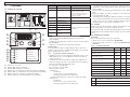 6
6
-
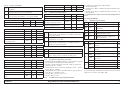 7
7
-
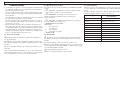 8
8
-
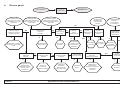 9
9
-
 10
10
-
 11
11
-
 12
12
-
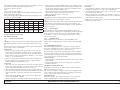 13
13
-
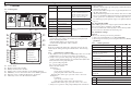 14
14
-
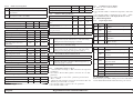 15
15
-
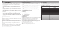 16
16
-
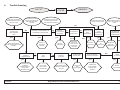 17
17
-
 18
18
-
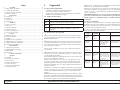 19
19
-
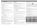 20
20
-
 21
21
-
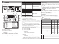 22
22
-
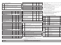 23
23
-
 24
24
-
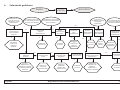 25
25
-
 26
26
-
 27
27
-
 28
28
-
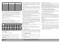 29
29
-
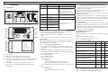 30
30
-
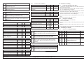 31
31
-
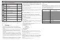 32
32
-
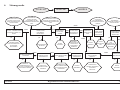 33
33
-
 34
34
-
 35
35
-
 36
36


Parker Hiross Hyperchill ICE015 Manual de usuario
- Tipo
- Manual de usuario
- Este manual también es adecuado para
en otros idiomas
Artículos relacionados

Otros documentos
-
 Strongline XT200900N Manual de usuario
-
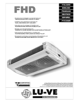 LU-VE LU-VE FHD Dual Discharge Unit Coolers Manual de usuario
-
Carrier AQUASNAP 30RH Guía de instalación
-
 Olimpia Splendid Sherpa AQUADUE S2 Guía de instalación
-
 Olimpia Splendid Sherpa AQUADUE TOWER S2 Manuale d'installazione
-
 Olimpia Splendid Sherpa S2 Manuale d'installazione
-
CIAT AQUACIAT 2 LD Series Manual de usuario
-
 Strongline XT503600N Manual de usuario
-
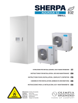 Olimpia Splendid Sherpa AQUADUE S2 Guía de instalación
-
PEDROLLO DG PED5 Manual de usuario


