
Phone:800-201-1360
Email:Acquaer@strategicretailsolutions.com
Web:www.acquaerpumps.com
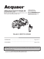
Model:CJE075/CJE100
FOR ENGLISH
.................................................................
Pages 02-13
FOR SPANISH
.................................................................
Pages 15-26
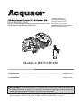
OWNER’S MANUAL
Convertible Jet Pump
Model:CJE075/CJE100
El manual del propietario
Bomba de Chorro Convertible
Modelo:CJE075/CJE100
WARNING: Read carefully and understand all ASSEMBLY AND OPERATION INSTRUCTIONS
before operating. Failure to follow the safety rules and other basic safety precautions may result
in serious personal injury
If you have any QUESTIONS, PROBLEMS, MISSING PARTS, please call our customer service
department at 800-201-1360 before returning to your retailer

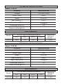
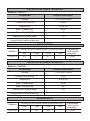
Property
Specifications
Voltage
Horse Power
Amps
Max. Head (ft.)
Max. Flow (GPH)
Discharge Size (in.)
Power cord length (ft.)
Model: CJE075
TECHNICAL SPECIFICATIONS
PERFORMANCE
Model
CJE075
GPH at 40psi discharge pressure
Maximum
pressure
shutoff
115/230V~60Hz
3/4HP
9.0/4.5A
150 ft.
1460@0ft
1 in.
-
0 ft. 50 ft. 100 ft. 150 ft.
1460 1130 750 150ft
-
Property
Specifications
Voltage
Horse Power
Amps
Max. Head (ft.)
Max. Flow (GPH)
Discharge Size (in.)
Power cord length (ft.)
Model: CJE100
TECHNICAL SPECIFICATIONS
PERFORMANCE
Model
CJE100
GPH at 40psi discharge pressure
Maximum
pressure
shutoff
115/230V~60Hz
1HP
9.6/4.8A
140 ft.
1460@0ft
1 in.
-
0 ft. 50 ft. 100 ft. 150 ft.
1460 1410 920 140ft
-

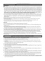
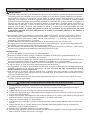
SAFETY INFORMATION
WARNING
This pump is meant to be used for shallow well or deep well applications. The pump can be equipped with
the included ejector by attaching it to the front of the pump, and can operate at a 25 ft. vertical lift from
the water level or less (shallow well pump). If the vertical lift of water is deeper than 25 ft., the pump can
be easily converted to deep well operation by installing the included ejector into the well and inserting
two pipes into the front of the pump. Then the pump can operate at an 80 ft. water level or less (deep well
pump). If the well's water level is deeper than 80 ft., return this pump to the store and purchase a
submersible well pump. NOTE: You must use the included ejector kit in either shallow (attach to
front of pump) or deep (attach to piping and place down in the well) applications.
CAUTION
The motor MUST NOT be started before the pump is primed!
ADDITIONAL SAFETY PRECAUTIONS
Know the pump applications, limitations, and potential hazards.1.
2.
3.
4.
5.
6.
7.
8.
9.
10.
11.
12.
13.
14.
Do not pump flammable or explosive liquids such as oil, gasoline, kerosene, ethanol, etc. Do not
use in the presence of flammable or explosive vapors. Using this pump with or near flammable
liquids can cause an explosion or fire, resulting in property damage, serious personal injury
and/or death.
This is a dual voltage motor. It can be wired for 230 volts (pre-set) or 115 volts, depending on the
power source.
This pump is equipped with a 20/40 PSI pressure switch. If the previous pump used a different
switch (30/50 PSI), you must reset the tank and/or switch.
In order for the pump and tank to operate properly, the tank needs to be drained of all water and
set to the proper pressure level BEFORE startup.
For safety, the pump motor has resetting thermal protector that automatically will turn off the pump
if it becomes too hot. Overuse of this feature will damage the pump and void the warranty.
Once the thermal protector detects that the pump has cooled to a safe temperature, it will allow
the pump to operate normally. If the pump is plugged in, it may restart unexpectedly.
Do not allow pump to be exposed to freezing temperatures. This can crack the cast iron, and void
the warranty.
Make certain the electrical power source is adequate for the requirements of the pump.
ALWAYS disconnect the power to the pump before servicing.
Release all pressure within system before servicing any component (drain all water from the
system).
Secure discharge line before starting pump. An unsecured discharge line could whip, possibly
causing personal injury and/or property damage.
Secure the pump on a solid base.
Check that all pipe connections are tight to minimize leaks.
Make certain the electrical circuit to the pump is protected by a dedicated 15-amp or larger fuse
or circuit breaker.
Never use extension cords with this pump!
Do not handle pump or pump motor with wet hands or when standing on wet or damp surface, or
in water.
Wear safety glasses at all times when working with pumps.
Follow all electrical and safety codes, particularly the National Electrical Code (NEC) and in the
workplace, the Occupational Safety and Health Act (OSHA).
This unit is designed only for use on 115 volts or 230 volts, 60 Hz. Directly connect pump wires
into properly grounded circuit board in accordance with the National Electrical Code and local
codes and ordinances. All wiring should be performed by a qualified electrician.
Protect the electrical cord from sharp objects, hot surfaces, oil, and chemicals. Avoid kinking the
cord. Do not use damaged or worn cords. Failure to properly wire this pump is dangerous and
will void the warranty.
Always disconnect the pump from its power source before inspection.
Do not touch the pump housing while it is operating, as the pump may be HOT and can cause
serious skin burns.
Do not disassemble the motor housing. This pump has NO repairable internal parts, and
disassembling may cause leakage or dangerous electrical wiring issues.

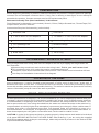
PREPARATION
Before beginning assembly of product, make sure all parts are present. Compare parts with package
contents list and hardware contents above. If any part is missing or damaged, do not attempt to
assemble the product. Contact customer service for replacement parts.
Estimated Assembly Time (New installation): 30-60 minutes
Tools Required for Assembly (not included): Wrench, Pliers, Phillips Screwdriver, Thread Tape, PVC
Purple Primer, and PVC Cement
Accessories Required for Assembly (not included):
DETERMINING THE DEPTH OF WELL
Using a weight tied to as string, determine the depth of the well by dropping the weight down the
well, and then:
Pressure Tank
1-1/4 in. and 1 in. PVC Adaptors
1-1/4 in. and 1 in. PVC Pipes
1 in. Discharge Tee
Tank Tee
Drain Valve
Foot Valve
1 in. MNPT x 1-1/4 in. SLIP PVC Adaptor
1-1/4 in. Single Drop Well Seal
Pressure Gauge
Relief Valve
1/4 in. Plug
Measure the ground level mark to where the string is wet. This is your well's water level.
This number must be 10 ft under the pump's normal pumping level.
Subtract 5 ft from this measured water level number. This number must be less than 25 feet.
See Step 3 of Installation Instructions for a diagram.
LOCATION OF THE PUMP
Decide on the area for the pump installation. Select a pump location with adequate space for future
pump maintenance. It can be located in the basement or utility room of the house, at the well, or
between the house and the well. If installed outside of the house, it should be protected by a pump
house with auxiliary heat to prevent possible freezing. The well also should be protected for sanitary
reasons. Mount the pump as close to the well as possible.
TANKS - PRE-CHARGED STORAGE
For best performance of the pump, it is recommended that you use a diaphragm pressure tank (not
included). It is best to have this in place before installing the pump. A pre-charged storage tank has
a flexible bladder or diaphragm that acts as a barrier between the compressed air and water. This
barrier prevents the air from being absorbed into the water and allows the water to be acted on by
compressed air at initially higher than atmospheric pressures (pre-charged). More usable water is
provided than with a conventional type tank. Pre-charged tanks are specified in terms of a
conventional tank. For example, a 20-gallon pre-charged tank will have the same usable water or
draw-down capacity as a 40-gallon conventional tank, but the tank is smaller in size.
CAUTION: In order for the pump and tank to operate properly, the pressure tank needs to be drained
of all water BEFORE INSTALLING THE NEW PUMP. After draining, if you are using the supplied
30/50 PSI pressure switch at the pre-set settings, add or adjust the air pressure in the tank to 28 PSI
of pressure BEFORE startup.

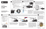
SHALLOW WELL INSTALLATION INSTRUCTIONS
NOTE: Use a minimum of 1-1/4” diameter PVC piping for the suction pipe for best performance.
1.
A 1 in. MNPT x 1-1/4 in. SLIP adaptor will be needed to make the connection to the pump.
WARNING
All joints and connections must be AIRTIGHT. A single leak will prevent the proper operation of the
pump. Wrap thread tape clockwise on all threaded connections. For all non-threaded connections,
you must use PVC Purple Primer and PVC Cement to ensure airtight seals. Measure all pipe lengths
before attaching.
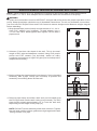
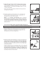
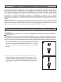
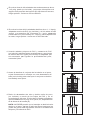
Wrap thread tape (not included) around threads of a 1-1/4 in.
male PVC adaptor (not included). Thread adaptor into a
1-1/4 in. foot valve. Hand tighten, then tighten 1/2 turn with a
pipe wrench.
Subtract 5 feet from the depth of the well. This is the total
length of PVC pipe and adaptors needed. Using PVC purple
primer and PVC cement (not included), attach as many
couplings and sections of rigid PVC pipe (not included) to the
adaptor as necessary.
Before sliding the pipe assembly into the well, firmly clamp the
assembly with a pipe clamp (not included) to prevent the
assembly from sliding down into the well.
1
2
3
2.
3.
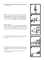
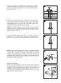
Remove pipe clamp and slide a well seal (not included) over
the PVC pipe and onto the well casing (not pictured). The PVC
pipe should extend approximately 12 in. from the well seal,
depending on the height of the pump (A).
4
4.
NOTE: DO NOT let the assembly slide down into well. Tighten
the well seal until the rubber gaskets are tight against the well
casing and the PVC pipe.

5
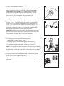
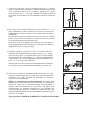
5.
6.
Using PVC purple primer and PVC cement, attach a 1-1/4 in.
PVC elbow (not included) onto the rigid PVC pipe extending
from the well seal.
6
7.
7
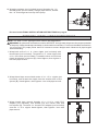
NOTE: This ejector must be attached to the front of the
pump for shallow well application! Locate ejector (B) and
place gasket (AA) over venturi tube (preassembled into
the ejector (B)) so that openings in gasket (AA) match
up with openings in ejector (B). Line up the bolts (BB)
with ejector (B). DO NOT REMOVE THE VENTURI TUBE!
8.
8
Slide the bolts (BB) through the bolt openings on both
sides of the ejector (B), through the gasket (AA), and
install the assembly onto the front of the pump (A). Tighten
the bolts (BB) securely. NOTE: The 1-1/4 in. hole of the
assembly goes on top, and the 1 in. hole goes on the bottom.
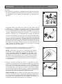
Wrap thread tape around the threads of a male PVC adaptor
(not included). Thread the adaptor into the front of the
ejector (B).
9.
9
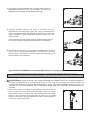
Using PVC purple primer and PVC cement, attach as many
sections of rigid 1 in. PVC pipe and couplings (not included)
as needed to connect the 1 in. male PVC adaptor to the 1 in.
PVC elbow.
Hardware Used
Ensure the pipe slopes slightly toward the well (to prevent
air trapping in the pipe).
BB
B
AA
B
A
BB
AA
A
B
B

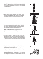
Wrap both ends of a 1 in. close nipple (not included) with
thread tape (not included). Thread the 1 in. close nipple into
a 1 in. foot valve (not included). Thread the other end of close
nipple into bottom of ejector (B). Hand tighten, then tighten 1
turn with pipe wrench.
10.
10
Wrap thread tape (not included) around threads of a 1 in.
discharge tee (not included). Using a pipe wrench, thread
the 1 in. discharge tee into top of the pump.
1.
1
Proceed to the FINAL INSTALLATION INSTRUCTIONS on page 9.
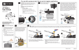
DEEP WELL INSTALLATION INSTRUCTIONS
NOTE: 1 in. and 1-1/4 in. piping must be used in this application.
WARNING! All joints and connections must be AIRTIGHT. A single leak will prevent the proper operation
of the pump. Wrap thread tape clockwise on all threaded connections. For all non-threaded connections,
you must use PVC purple primer and PVC cement to ensure airtight seals. Measure all pipe lengths
before attaching.
Wrap thread tape around both ends of a 1 x 5 in. nipple (not
included), and thread the nipple into the smaller hole of the
ejector (B). Hand tighten, then tighten 1 turn with pipe wrench.
2.
2
Wrap thread tape around threads of a 1-1/4 in. male PVC
adaptor (not included), and thread over the venturi tube and
into ejector (B). Thread a 1 in. female PVC adaptor (not included)
onto the 1 x 5 in. nipple. Hand tighten, then tighten 1 turn with
pipe wrench.
3.
3
A
B
B
B
B

4
4.
5.
Using PVC purple primer and PVC cement (not included),
attach as many couplings and sections of rigid PVC pipe
(not included) to the adaptor as it takes to equal the depth
of the well minus 5 ft.
6.
6
Before sliding the pipe assembly into the well, firmly
clamp the assembly with a pipe clamp (not included) to
prevent the assembly from sliding down into the well.
7.
7
Remove pipe clamp and slide well seal (not included)
over the PVC pipes and onto the well casing. The PVC
pipe should extend approximately 12 in. from the well
seal, depending on the height of the pump (A).
Cut the 1 in. pipe 2 in. shorter than the 1-1/4 in. pipe.
Smooth rough edges. Using PVC purple primer and PVC
cement (not included), attach a 1 in. PVC elbow and a
1-1/4 in. PVC elbow (both facing the pump) to the pipes
extending from the well seal.
8.
Wrap thread tape around the threads of a 1-1/4 in. male
PVC adaptor (not included). Thread the adaptor into the
top hole in the front of the pump (A).
Wrap thread tape around the threads of a 1 x 5 in. nipple
(not included). Thread the nipple into the bottom hole in
front of the pump (A).
NOTE: DO NOT let assembly slide down into well.
Tighten the well seal until rubber gaskets are tight
against the well casing and the PVC pipes.
Wrap thread tape around the threads of a 1 in. female
PVC adaptor (not included). Thread the adaptor onto the
1 x 5 in. nipple.
5
8
A

9.
9
Using PVC purple primer and PVC cement, attach as many
sections of rigid 1 in. and 1-1/4 in. PVC pipe and couplings
(not included) as needed to connect the 1-1/4 in. male PVC
adaptor and the 1 in. female PVC adaptor to the 1 in. and
1-1/4 in. PVC elbows.
10.
10
Wrap thread tape around threads of a 1 in. discharge tee
(not included). Using a pipe wrench, thread the 1 in.
discharge tee into top of the pump (A).
Ensure the pipe slopes slightly toward the well (to prevent
air trapping in the pipe).
NOTE: It is strongly recommended that a Pressure
Regulator Kit (not included) be used instead of a regular tee.
This will help to regulate fluctuations in water pressure that
can commonly be found in deep well jet pumps. Failure to
use this item may result in a loss of prime and/or irregular
water pressure.
Proceed to the FINAL INSTALLATION INSTRUCTIONS below.
FINAL INSTALLATION INSTRUCTIONS
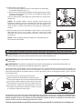
1.
1
Wrap thread tape around the threads of a 1 in. male PVC
adaptor (not included), and thread the adaptor into the
discharge tee (or Pressure Regulator).
2.
2
Wrap all threads with thread tape. In order for the pump (A)
and the pressure tank (not included) to operate properly, the
pressure tank needs to be drained of all water BEFORE
INSTALLING IT TO THE PUMP. Thread a 10 in. tank tee (not
included), or another necessary size tee into the diaphragm
of the pressure tank.
Plug one outlet on top of the tank tee with a 1/4 in. plug and
install a pressure gauge (not included) on the other outlet on
top of the tank tee. Thread two 1 in. female PVC adaptors (not
included) into the two inlet sides of tank tee. Thread a 1/2 in.
relief valve (not included) and a 1/2 in. drain valve (Item not
included) to the front of the tank tee.
These final steps are the same for both shallow well and deep well application.
A
A
A

3
3.
4.
Air pressure in the tank must be 2 PSI lower than the
"cut-in" of the pressure switch.
4
Using PVC purple primer and PVC cement, attach a
section of 1 in. PVC pipe (not included) as needed to
connect the 1 in. male PVC adaptor on the discharge tee
to the 1 in. female PVC adaptor (not included) on the
tank tee. Attach another section of 1 in. PVC pipe as
needed to connect the other 1 in. female PVC adaptor on
the tank tee to the water system from the house.
NOTE: The pump (A) has a 30/50 PSI pressure switch,
which means the "cut-in" is 30 PSI; therefore, the tank
needs to be set to 28 PSI. To check the pressure in the
tank, use a tire pressure gauge (not included). If more
air is needed, add air to the tank with a tire pump or air
compressor. If less is needed, bleed out some air.
CAUTION! Never install a shut-off valve between the pump
and the tank, as this can cause excessive friction loss and
can damage the pressure switch and/or pump. If necessary,
only install a fully open gate valve (not included).
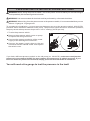
To prime, remove both:
a. The plug from the top of the discharge tee
(water will be filled in here), and;
b. The plug in front of the discharge tee on the pump
(this is to allow air to vent out while priming).
Fill the discharge tee with water until water overflows.
NOTE: It may take several minutes to fill the pipes and the
pump (A) completely.Wrap the discharge tee plug and priming
plug threads with thread tape and re-attach to the pump (A).
Tighten with wrench.
5.
5
6.
6
This pump (A) is pre-wired at 230 volts. If the power source
is 115 volts, remove the electrical housing cover. Flip the
switch to 115 volts. Replace the cover.
NOTE: All electrical work should be performed by a licensed
electrician.
A

PRESSURE SWITCH INSTALLATION INSTRUCTIONS
WARNING! Before wiring the pressure switch, turn off the power source to which you are connecting to
avoid potentially life threatening electrical shock.
WARNING! It is recommended all electrical work be performed by a licensed electrician.
WARNING! When wiring from the power source to the pressure switch, it is recommended that you use
either a 14-gauge or 12-gauge cord.
To complete the installation, you must connect the power source to the pressure switch. A 30/50 PSI
pressure switch has been installed on the pump. The pressure switch allows for automatic operation;
the pump starts when pressure drops to the “cut-in” setting (30 PSI pre-set).
1.
To wire the pressure switch:
Remove the pressure switch cover on pump
to expose the wiring terminals.
Connect the green ground wire of the power
supply to the switch ground terminal.
Connect the power supply wires to the two
outside terminals marked “LINE” and replace
the switch cover.
If you had a different pressure switch on the old pump (ex. 20/40 PSI), make sure to adjust the
pressure in your tank to 28 PSI! You may need an air compressor to add air pressure. If you
have too much air pressure in the tank, simply press the air stem down to release air.
You will need a tire gauge to test the pressure in the tank!
1

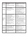
Problem Possible Cause Corrective Action
Pump does
not start or
run
Pump will
not prime
1.
2.
3.
4.
Power off
Blown fuse or tripped breaker
Faulty pressure switch
Motor overload tripped
1.
2.
3.
4.
Turn power on or call power company
Replace fuse or reset circuit breaker
Replace switch
Let cool. Overload will automatically
reset
1.
2.
3.
4.
5
Not enough water
Pump wired incorrectly
Plugged venturi or nozzle
Foot valve is plugged or leaks
Low water level
1.
2.
3.
4.
5.
Stop motor; remove pressure gauges
or prime plug; fill housing pipes with
water
Wire pressure switch properly; call
customer service
Remove ejector and venturi or nozzle;
clean
Replace foot valve or dig well deeper
In deep well application, foot valve
and ejector must be below water level
Pump
operates
but pumps
little or no
water
1.
2.
3.
4.
5.
6.
7.
8.
9.
10.
11.
Water level below pump intake
Discharge not vented while priming
Leaking in piping on well sideof
pump
Well screen or inlet strainer
clogged
Foot valve may be cloggedor stuck
closed
Pump not fully primed
Water level below maximum lift
specification
Undersized piping
Lncorrect jet for application
Undersized pump
Improper voltage
Lower suction pipe further into well
Open faucet, repeat priming procedure
Repair piping as needed
Clean or replace as necessary
Clean or replace as needed
Continue priming, pausing every 5
minutes to cool pump body. Refill
pump as needed
Select applicable pump
Replace as needed
Purchase a jet matched to the system
when replacing another brand pump
Change to install a pump with higher
horsepower
Check voltage switch
Pump starts
and stops
too often
1.
2.
3.
4.
5.
Incorrect tank pre-charged
Ruptured diaphragm/bladder
(pre-charged tank)
Leak in house piping
Foot valve or check valve stuck
open
Improperly adjusted pressure
switch
1.
2.
3.
4.
5.
Add or release air as needed
Replace tank
Locate and repair leak or reconnect
Remove and replace
Readjust or replace switch
1.
2.
Leak in house piping
Improper setting of pressure
switch
1.
2.
Locate and repair leak or reconnect
Reset or replace pressure switch
Pump does
not shut off
1.
2.
3.
4.
5.
6.
7.
8.
9.
10.
11.

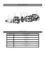
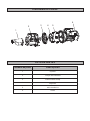
PARTS DIAGRAM
PARTS LIST
Part No.
Description
1
2
3
4
5
6
1
2
3
4
6
5
ejector
pump body
drain cover
impeller
mechanical seal
motor

Phone:800-201-1360
Email:Acquaer@strategicretailsolutions.com
Web:www.acquaerpumps.com
Modelo:CJE075/CJE100
OWNER’S MANUAL
Convertible Jet Pump
Model:CJE075/CJE100
El manual del propietario
Bomba de Chorro Convertible
Modelo:CJE075/CJE100
FOR ENGLISH
.................................................................
Pages 02-13
FOR SPANISH
.................................................................
Pages 15-26
ADVERTENCIA: Lea cuidadosamente y comprenda todas las INSTRUCCIONES DE MONTAJE
Y OPERACIÓN antes de operar. Si no se siguen las reglas de seguridad y otras precauciones
básicas de seguridad puede resultar en lesiones personales graves
Si tiene cualquier PREGUNTAS, PROBLEMAS, PIEZAS FALTANTES, por favor llame a nuestro
departamento de servicio al cliente al 800-201-1360 antes de devolver a la tienda

Propiedad
Especificaciones
Modelo: CJE075
ESPECIFICACIONES TÉCNICAS
RENDIMIENTO
Modelo
CJE075
La presión
máxima de
apagado
115/230V~60Hz
3/4HP
9.0/4.5A
45m
92
1 in.
-
45m
0m 15m 30m 45m
92 71 47 -
Voltaje
Caballo de fuerza
Amperios
Max. Cabeza(m)
Max. Flujo(LPM)
tamaño de la descarga
Longitud del cable eléctrico
LPM de agua a un total de metros de cabeza de 40 psi
Propiedad
Especificaciones
Modelo: CJE100
ESPECIFICACIONES TÉCNICAS
RENDIMIENTO
Modelo
CJE100
La presión
máxima de
apagado
115/230V~60Hz
1HP
9.6/4.8A
42m
92
1 in.
-
42m
0m 15m 30m 45m
92 89 58 -
Voltaje
Caballo de fuerza
Amperios
Max. Cabeza(m)
Max. Flujo(LPM)
tamaño de la descarga
Longitud del cable eléctrico
LPM de agua a un total de metros de cabeza de 40 psi

PRECAUCIÓN
El motor NO DEBE iniciarse antes se ceba la bomba!
PRECAUCIONES ADICIONALES DE SEGURIDAD
Conozca las aplicaciones, limitaciones y riesgos potenciales de la bomba.1.
2.
3.
4.
5.
6.
7.
8.
9.
10.
No bombee líquidos inflamables o explosivos, tales como aceite, gasolina, queroseno, etanol,
etc. No utilice en presencia de vapores inflamables o explosivos. El uso de esta bomba con o
cerca de líquidos inflamables puede causar una explosión o un incendio, causando daños
materiales, lesiones graves y / o muerte.
Este es un motor de doble voltaje. Puede ser instalado de 230 voltios (preestablecidos) o 115
voltios, dependiendo de la fuente de alimentación.
Esta bomba está equipada con un interruptor de presión 20/40 PSI. Si la bomba anterior utiliza un
interruptor diferente (30/50 PSI), debe restablecer el depósito y / o el interruptor.
Para que la bomba y el tanque de funcionen correctamente, el tanque debe ser drenado de toda
el agua y ajuste al nivel de presión adecuado antes del arranque.
Por seguridad, el motor de la bomba ha restablecido el protector térmico que automáticamente se
apagará la bomba si se calienta demasiado. El uso excesivo de esta característica puede
dañar la bomba y anular la garantía.
Una vez que el protector térmico detecta que la bomba se haya enfriado a una temperatura
segura, que permitirá que la bomba funcione normalmente. Si la bomba está conectada, se puede
reiniciar inesperadamente.
No permita que la bomba esté expuesta a temperaturas bajo cero. Esto puede romper el hierro
fundido, y anular la garantía.
Asegúrese de que la fuente de alimentación eléctrica sea adecuada a las exigencias de la
bomba.
SIEMPRE desconecte la energía a la bomba antes de prestar servicio.
Libere toda la presión dentro del sistema antes de dar servicio a cualquier componente (drenar
toda el agua del sistema).
Asegure la línea de descarga antes de arrancar la bomba. Una tubería de descarga sin garantía
podría moverse y causar lesiones personales y / o daños materiales.
Asegure la bomba sobre una base sólida.
Compruebe que todas las conexiones de las tuberías estén bien apretadas para minimizar las
fugas.
Asegúrese de que el circuito eléctrico de la bomba está protegido por una de 15 amperios
dedicado o mayor fusible o disyuntor.
Nunca utilice cables de extensión con esta bomba!
No manipule la bomba o bombee el motor con las manos mojadas o cuando esté parada sobre
una superficie mojada o húmeda, o en agua.
Siempre desconecte la bomba de la fuente de alimentación antes de la inspección.
No toque la carcasa de la bomba mientras está en funcionamiento, ya que la bomba puede estar
CALIENTE y puede causar quemaduras graves en la piel.
No desmonte la carcasa del motor. Esta bomba NO tiene partes internas reparables, y desmontaje
puede causar problemas de cableado eléctrico peligrosos o fuga.
INFORMACIÓN DE SEGURIDAD
ADVERTENCIA
Esta bomba está destinada a ser utilizada para pozos poco profundos o aplicaciones de pozos profundos.
La bomba puede ser equipada con el eyector incluido por lo conecta a la parte delantera de la bomba, y
puede operar a 25 pies. De elevación vertical desde el nivel de agua o menos (bomba de pozo poco
profundo). Si la elevación vertical de agua es más profunda de 25 pies, la bomba se puede convertir
fácilmente a la operación de pozo profundo mediante la instalación del eyector incluido en el pozo y la
inserción de dos tubos en la parte frontal de la bomba. A continuación, la bomba puede funcionar a un
nivel de agua de 80 pies. o menos (bomba de pozo profundo). Si el nivel del agua del pozo es más
profundo que 80 pies., Regresar esta bomba a la tienda y comprar una bomba sumergible de pozo.
NOTA: Debe utilizar el equipo de eyector incluido en cualquiera de las aplicaciones de poca
profundidad (adjuntar a la parte delantera de la bomba) o profundas (adjuntar a las tuberías y
colocar en el pozo).

PREPARACIÓN
Antes del montaje del producto, asegúrese de tener todas las piezas. Compare las piezas con la
lista de contenido del paquete y el contenido de hardware anteriormente. Si alguna parte falta o está
dañada, no intente montar el producto. Póngase en contacto con el servicio al cliente para piezas de
repuesto.
Tiempo estimado de instalación (Nueva instalación): 30-60 minutos
Herramientas necesarias para el montaje (no incluidas): Llave, alicates, Phillips destornillador, cinta
de hilo, cebador púrpura de PVC y cemento de PVC
Accesorios necesarias para el montaje (no incluido):
DETERMINACIÓN DE LA PROFUNDIDAD DE POZO
Usando un peso atado a que la cadena de determinar la profundidad del pozo al dejar caer el peso
en el pozo, y luego:
Tanque de presión
1-1/4 pulg. y 1 pulg. Adaptadores de PVC
1-1/4 pulg. y 1 pulg. Tubos de PVC
1 pulg. Soporte de Descarga
Soporte de tanque
Válvula de drenaje
Válvula de pie
1-1/4 pulg. Sello de pozo de gota solo
Manómetro
Válvula de seguridad
1/4 pulg. Enchufe
Mida la marca a nivel del suelo, donde la cadena está mojado. Este es el nivel de agua de
pozo.
Este número debe ser de 10 pies bajo el nivel normal de bombeo de la bomba.
Sustraiga 5 pies de este número del nivel de agua medido. Este número debe ser inferior a 2
pies.
Consulte el paso 3 de las instrucciones de instalación de un diagrama.
UBICACIÓN DE LA BOMBA
Decida sobre el área para la instalación de la bomba. Seleccione una ubicación de la bomba con un
espacio adecuado para el futuro mantenimiento de las bombas. Puede ser ubicado en el sótano o el
lavadero de la casa, junto al pozo, o entre la casa y el pozo. Si se instala fuera de la casa, que debe
ser protegido por una estación de bombeo con calefacción auxiliar para evitar una posible
congelación. El pozo debe protegerse también por razones sanitarias. Monte la bomba tan cerca de
la mejor manera posible.
1 pulg. MNPT x 1-1/4 pulg. SLIP adaptador de PVC
Use gafas de seguridad en todo momento cuando se trabaja con bombas.
Siga todos los códigos eléctricos y de seguridad, en particular el Código Eléctrico Nacional
(NEC) y en el lugar de trabajo, la Ley de Seguridad y Salud Ocupacional (OSHA).
Esta unidad está diseñada sólo para uso en 115 voltios o 230 voltios, 60 Hz. Directamente
conecte cables de la bomba en la placa de circuito de tierra adecuada de acuerdo con el Código
Eléctrico Nacional y los códigos y ordenanzas locales. Todo el cableado debe ser realizado por
un electricista calificado.
Proteja el cable eléctrico de objetos afilados, superficies calientes, aceite y productos químicos.
Evite torcer el cable. No utilice cables dañados o desgastados. No realice el cableado
correctamente esta bomba es peligroso y anulará la garantía.
11.
12.
13.
14.
PRECAUCIONES ADICIONALES DE SEGURIDAD

1
2
INSTRUCCIONES PARA LA INSTALACIÓN DE POZO POCO PROFUNDO
NOTA: Use tubería de PVC de diámetro mínimo de 1-1 / 4 " para la tubería de succión para un mejo
rendimiento.
1.
Se necesitará un 1 pulg. MNPT x 1-1 / 4 pulg. SLIP adaptador para hacer la conexión a la bomba.
ADVERTENCIA
Todas las juntas y las conexiones deben ser HERMÉTICAS. Una sola fuga impedirá el correcto
funcionamiento de la bomba. Envuelve el hilo cinta de las agujas del reloj en todas las conexiones
roscadas. Para todas las conexiones sin rosca, debe utilizar Cebador púrpura de PVC y cemento
de PVC para asegurar sellos herméticos. Medir todas las longitudes de tubería antes de conectar.
Envuelva la cinta de hilo (no incluido) alrededor de las roscas
de un 1-1 / 4 pulg. Adaptador de PVC macho (no incluido).
Enrosque el adaptador en una válvula de pie de 1-1 / 4 pulg.
Apriete con la mano, luego apriete 1/2 de vuelta con una llave
de tubo.
Sustraiga 5 pies de la profundidad del pozo. Esta es la
longitud total de la tubería y adaptadores necesarios PVC.
El uso de cebador púrpura de PVC y cemento de PVC (no
incluido), adjuntar tantos acoplamientos y secciones de
tubería de PVC rígido (no incluido) al adaptador según sea
necesario.
2.
TANQUES - ALMACENAMIENTO PRECARGADO
Para un mejor rendimiento de la bomba, se recomienda el uso de un tanque de presión de diafragma
(no incluido). Lo mejor es tener esto en su lugar antes de instalar la bomba. Un tanque de
almacenamiento de pre-cargada tiene una vejiga flexible o diafragma que actúa como una barrera
entre el aire comprimido y agua. Esta barrera impide que el aire sea absorbido en el agua y permite
que el agua sea sobre la que actúa el aire comprimido en un principio más alta que la presión
atmosférica (pre-cargada). Se proporciona agua más utilizable que con un depósito de tipo
convencional. Tanques previamente cargadas se especifican en términos de un tanque
convencional. Por ejemplo, un tanque de 20 galones pre-cargado tendrá la misma agua utilizable o
capacidad de reducción de un tanque convencional de 40 galones, pero el tanque es de menor
tamaño.
PRECAUCIÓN: Para que la bomba y el tanque funcionen correctamente, el tanque de presión debe
ser drenado de toda el agua ANTES DE INSTALAR LA BOMBA NUEVA. Después del drenaje, si está
utilizando el interruptor de presión 30/50 PSI suministrado con los ajustes preestablecidos, añadir o
ajustar la presión de aire en el tanque a 28 PSI de presión ANTES DEL arranque.

5.
6.
Usando cebador púrpura de PVC y cemento de PVC,
adjunte un 1-1 / 4 pulg. codo de PVC (no incluido) en el
tubo de PVC rígido que se extiende desde el sello del pozo.
7.
NOTA: Este eyector debe estar unido a la parte delantera
de la bomba para la aplicación pozo poco profundo!Localiza
eyector (B) y coloque el empaque (AA) sobre el tubo de
Venturi (preensamblado en el eyector (B)) de manera que
las aberturas en la junta (AA) coinciden con las aberturas de
expulsión (B). Alinee los pernos (BB) con eyector (B). NO
RETIRE EL TUBO VENTURI!
Deslice los pernos (BB) a través de las aberturas de perno
en ambos lados del eyector (B), a través de la junta (AA), e
instalar el conjunto sobre la parte delantera de la bomba (A).
Apriete los tornillos (BB) de forma segura. NOTA:. El 1-1 / 4
pulg. agujero del conjunto va en la parte superior, y el 1 pulg.
agujero va en la parte inferior.
Hardware Utilizado
5
6
7
BB
B
AA
B
A
BB
AA
3
4
Antes de deslizar el conjunto de la tubería en el pozo,
sujete firmemente el montaje con una abrazadera de tubo
(no incluido) para evitar que el conjunto se deslice hacia
abajo en el pozo.
3.
Retire la abrazadera de tubo y deslice el sello del pozo
(no incluido) a través del tubo de PVC y en el revestimiento
del pozo (no se muestra). El tubo de PVC debe extenderse
aproximadamente 12 pulg. del sello de pozo, así,
dependiendo de la altura de la bomba (A).
4.
NOTA: NO DEBE permitir que el montaje se deslice hacia
abajo en el pozo. Apriete el sello del pozo hasta que las
juntas de goma están apretadas contra el revestimiento del
pozo y la tubería de PVC.

10
Envuelva los dos extremos de un 1 pulg. boquilla de cierre
(no incluido) con cinta de hilo (no incluido). Pase el 1 pulg.
boquilla de cierre en una 1 pulg. válvula de pie (No incluido).
Pase el otro extremo de la boquilla de cierre en la parte
inferior del eyector (B). Apriete con la mano, luego apriete 1
vuelta con la llave de tubo.
10.
Envuelva la cinta de hilo (no incluido) alrededor de los hilos
de un 1 pulg. soporte de descarga (no incluido). Con una
llave de tubo, enrosque el 1 pulg. soporte de descarga en la
parte superior de la bomba.
1.
Siga INSTRUCCIONESDE LA INSTALACIÓN FINAL de la página 22.
INSTRUCCIONES DE INSTALACIÓN DE POZO PROFUNDO
NOTA: 1 pulg. y 1-1/4 pulg. tubería debe ser utilizada en esta aplicación.
ADVERTENCIA: Todas las juntas y las conexiones deben ser HERMÉTICAS. Una sola fuga impedirá el
correcto funcionamiento de la bomba. Envuelve el hilo cinta de las agujas del reloj en todas las
conexiones roscadas. Para todas las conexiones sin rosca, debe utilizar cebador púrpura de PVC y el
cemento de PVC para asegurar sellos herméticos. Mida todas las longitudes de tubería antes de
conectar.
1
B
8.
Envuelva la cinta alrededor de los hilos de rosca de un
adaptador macho de PVC (no incluido). Enrosque el
adaptador en la parte frontal del eyector (B).
9.
Usando cebador púrpura de PVC y cemento de PVC,
adjuntar las secciones de rígido de 1 pulg. de tubería de
PVC y acoplamientos (no incluidas) según sea necesario
para conectar el 1 pulg. adaptador de PVC macho a la 1 en.
codo de PVC.
Asegúrese de que los tubos inclinen ligeramente hacia el
pozo (para evitar el atrapamiento de aire en la tubería).
8
9
A
B
B

Envuelva cinta de hilo alrededor de ambos extremos de un
1 x 5 pulg. pezón (no incluido), y enrosque la boquilla en el
agujero más pequeño del eyector (B). Apriete con la mano,
luego apriete 1 vuelta con la llave de tubo.
2.
Envuelva la cinta de hilo alrededor de hilos de un 1-1 / 4pulg.
adaptador macho de PVC (no incluido), y el hilo sobre el tubo
venturi y en expulsor (B). Enrosque un 1 pulg. adaptador
hembra de PVC (no incluido) al 1 x 5 pulg. pezón.Apriete con
la mano, luego apriete 1 vuelta con la llave de tubo.
3.
2
3
B
B
4
6
5
4.
5.
Usando cebador púrpura de PVC y cemento de PVC
(no incluido), adjunte tantos acoplamientos y secciones
de tubería de PVC rígido (no incluido) al adaptador que
sea necesario para igualar la profundidad del pozo,
menos de 5 pies.
6.
Antes de deslizar el conjunto de la tubería en el pozo,
sujete firmemente el montaje con una abrazadera de
tubo (no incluido) para evitar que el conjunto se deslice
hacia abajo en el pozo.
Retire la abrazadera de tubo y deslice sello de pozo
(no incluido) a través de los tubos de PVC y en el
revestimiento del pozo. El tubo de PVC debe extenderse
aproximadamente 12 pulg. de la junta, así, dependiendo
de la altura de la bomba (A).
NOTA: NO DEBE permitir que el montaje se deslice hacia
abajo en el pozo. Apriete el sello del pozo hasta que las
juntas de goma están apretadas contra el revestimiento
del pozo y la tubería de PVC.

9
10
A
A
9.
Usando cebador púrpura de PVC y cemento de PVC,
adjuntar tantas secciones de rígida 1 pulg. y 1-1 / 4 pulg.
de tubería de PVC y acoplamientos (no incluido) según
sea necesario para conectar el 1-1 / 4 pulg. adaptador de
PVC macho y el 1 pulg. adaptador de PVC hembra a la 1
pulg. y 1-1 / 4 pulg. codos de PVC.
10.
Envuelva la cinta hilo alrededor de los hilos de un 1 pulg.
Soporte de descarga (no incluido). Con una llave de tubo,
enrosque el 1 pulg. Soporte de descarga en la parte
superior de la bomba (A).
Asegúrese de que los tubos inclinen ligeramente hacia el
pozo (para evitar el atrapamiento de aire en la tubería).
NOTA: Se recomienda encarecidamente que un Equipo
Regulador de Presión (artículo # 0134154, no incluido) se
utiliza en lugar de un soporte regular. Esto ayudará a
regular las fluctuaciones en la presión del agua que
normalmente se pueden encontrar en las bombas de
chorro de pozo profundo. Fracaso de utilización de este
material puede resultar en una pérdida de presión de agua
primer y / o irregular.
Siga siguientes INSTRUCCIONESDE LA INSTALACIÓN FINAL.
Envuelva la cinta hilo alrededor de los hilos de un 1 x 5 pulg.
pezón (no incluido). Enrosque el pezón en el orificio inferior
en la parte delantera de la bomba (A).
Envuelva la cinta alrededor de los hilos de rosca de un 1
pulg. adaptador de PVC hembra (no incluido). Enrosque el
adaptador en el 1 x 5 pulg. pezón.
8
A
7
7.
Corte el 1 pulg. tubo 2 pulg. más corto que el de 1-1 / 4 pulg.
tubo. bordes ásperos suaves. Usando cebador púrpura de
PVC y cemento de PVC (no incluido), adjunte un 1 pulg.
codo de PVC y un 1-1 / 4 pulg. codo de PVC (tanto frente a
la bomba) a los tubos que se extienden desde el sello del
pozo.
8.
Envuelva cinta de hilo alrededor de los hilos de un 1-1 / 4
pulg. adaptador de PVC macho (no incluido). Enrosque el
adaptador en el orificio superior en la parte delantera de la
bomba (A).

1
2
A
INSTRUCCIONESDE LA INSTALACIÓN FINAL
1.
Envuelva la cinta de hilo alrededor de los hilos de rosca de
un 1 pulg. adaptador macho de PVC (no incluido), y enrosque
el adaptador en el soporte de descarga (o regulador de
presión).
2.
Envuelva todos los hilos con cinta de hilo. Para que la
bomba (A) y el tanque de presión (no incluido) funcionen
correctamente, el tanque de presión debe ser drenado de toda
el agua ANTES DE INSTALARLO EN LA BOMBA. Enrosque un
10 pulg. Soporte de tanque (no incluido), u otro soporte del
tamaño necesario en el diafragma del tanque de presión.
Conecte una salida en la parte superior del soporte del tanque
con un 1/4 pulg. enchufe e instale un medidor de presión (no
incluido) en la otra salida en la parte superior de soporte del
tanque. Enrosque dos 1 pulg. adaptadores hembra de PVC (no
incluidos) en los dos lados de entrada de soporte de tanque.
Enrosque una 1/2 pulg. válvula de alivio (no incluido) y un 1/2
pulg. válvula de drenaje (artículo no incluido) a la parte
delantera del soporte del tanque.
Estos pasos finales son los mismos para ambos pozos poco profundos y aplicación de pozo
profundo.
3
4
3.
4.
La presión del aire en el tanque debe ser de 2 PSI más
baja que la de "corte" del interruptor de presión.
Usando cebador púrpura de PVC y cemento de PVC,
adjuntar una sección de 1 pulg. tubería de PVC (no incluido)
según sea necesario para conectar el 1 pulg. adaptador de
PVC macho en el soporte de descarga a la 1 pulg. adaptador
hembra de PVC (no incluido) en el soporte del tanque. Añada
otra sección de 1 pulg. tubería de PVC, según sea necesario
para conectar el otro 1 pulg. adaptador de PVC femenina en
el soporte del tanque al sistema de agua de la casa.
NOTA: La bomba (A) tiene un interruptor de presión
30/50 PSI, lo que significa el "corte" es de 30 PSI; Por lo
tanto, el tanque debe ser ajustado a 28 PSI. Para
comprobar la presión en el depósito, utilice un medidor
de presión de los neumáticos (no incluido). Si se necesita
más aire, añada aire al tanque con una bomba de aire o
un compresor de aire. Si se necesita menos, desangrarse
un poco de aire.
PRECAUCIÓN! Nunca instale una válvula de cierre entre la
bomba y el tanque, ya que esto puede causar la pérdida por
fricción excesiva y puede dañar el interruptor de presión y / o
la bomba. Si es necesario, sólo se instala una válvula de
compuerta completamente abierta (no incluido).

INSTRUCCIONES DE INSTALACIÓN DEL INTERRUPTOR DE PRESION
DVERTENCIA! Antes de cablear el interruptor de presión, apague la fuente de alimentación a la que se
está conectando a evitar potencialmente amenaza de descarga eléctrica.
DVERTENCIA! Se recomienda todos los trabajos eléctricos ser realizados por un electricista
autorizado.
DVERTENCIA! Al realizar el cableado de la fuente de alimentación al interruptor de presión, se
recomienda que usted use un cable de calibre 14 o calibre 12.
Para completar la instalación, debe conectar la fuente de alimentación al interruptor de presión. Un
interruptor de presión 30/50 PSI se ha instalado en la bomba. El interruptor de presión permite la
operación automática; la bomba arranca cuando la presión cae a la configuración de "corte" (30 PSI
pre-establecido).
1.
Para conectar el interruptor de presión:
Retire la tapa del interruptor de presión de la
bomba para exponer los terminales de cableado.
Conecte el cable verde de tierra de la fuente de
alimentación al terminal de interruptor de tierra.
Conectar los cables de alimentación a los dos
terminales exteriores marcados "LINE" y vuelva
a colocar la tapa del interruptor.
Si usted tenía un interruptor de presión diferente en la bomba antigua (p. 20/40 PSI),asegúrese de
ajustar la presión en el tanque a 28 PSI! Es posible que necesite un compresor de aire para
añadir presión de aire. Si usted tiene demasiada presión de aire en el tanque, sólo tiene que
pulsar el tallo aire hacia abajo para liberar el aire.
Usted necesitará un medidor de presión para medir la presión en el tanque!
1
5
6
Para cebar, retire ambos:
a. El enchufe de la parte superior del soporte de descarga
(se llenará de agua aquí) , y;
b. El enchufe en frente del soporte de descarga de la bomba
(esto es para permitir que el aire de ventilación hacia fuera
mientras el cebado).
Llene el soporte de descarga con agua hasta que el agua se
desborda.
NOTA: Se puede tardar varios minutos para llenar las
tuberías y la bomba (A) por completo.Envuelva el enchufe de
soporte de descarga y hilo de enchufe de de cebado con
cinta de hilo y vuelva a conectar a la bomba (A). Apriete con
la llave.
6.
6
Esta bomba (A) es pre-cableado a 230 voltios. Si la fuente d
alimentación es de 115 voltios, retire la tapa de la caja
eléctrica. Active el interruptor de 115 voltios. Vuelva a colocar
la cubierta.
NOTA: Todo el trabajo eléctrico debe ser realizado por un
electricista autorizado.
A
5.

Problema Causa posible Acción correctiva
La bomba
no arranca
o funciona
La bomba
no se ceba
1.
2.
3.
4.
Sin batería
Fusible fundido o se disparó el
disyuntor
Interruptor de presión defectuoso
sobrecarga del motor actuada
1.
2.
3.
4.
Encender o llamar a la compañía
eléctrica
Cambiar el fusible o reiniciar el
disyuntor
Reemplazar el interruptor
Dejar enfriar. La sobrecarga se
restablecerá automáticamente
1.
2.
3.
4.
5.
No hay suficiente agua
Bomba mal cableado
Venturi o boquilla obstruido
Válvula de pie está enchufado o
fugas
Nivel bajo de agua
1.
2.
3.
4.
5.
Parar motor; quitar los medidores de
presión o tapón de cebado; llenar las
tuberías de viviendas con agua
Cable camiba correctamente; llamar
a atención al cliente
Eliminar eyector y venturi o la
boquilla; limpiar
Reemplazar la válvula de pie o cavar
el pozo más profundo
En aplicación de pozo profundo,
válvula de pie y el eyector debe estar
por debajo del nivel del agua
La bomba
funciona
pero bombea
poca o
ninguna
agua
1.
2.
3.
4.
5.
6.
7.
8.
9.
10.
11.
Nivel del agua por debajo de
entrada de la bomba
La descarga no ventilada,
mientras que el cebado
Fuga en la tubería en el lado de la
pared de la bomba
Pantalla ocolador de entrada de
pozo obstruido
Válvula de pie puede estar
obstruida o atascado cerrada
Bomba no está totalmente cebada
Nivel del agua debajo de la
especificación máxima de
elevación
Tuberías de tamaño insuficiente
Chorro incorrecto para la
aplicación
Bomba de tamaño insuficiente
Voltaje incorrecto
Bajar el tubo de succión aún más en
el pozo
Abrir el grifo, repetir el procedimiento
de cebado
Reparar las tuberías, según sea
necesario
Limpiar o reemplazar si es necesario
Limpiar o reemplazar si es necesario
Continuar cebado, haciendo una
pausa cada 5 minutos para enfriar el
cuerpo de la bomba. Volver a llenar la
bomba según sea necesario
Seleccionar la bomba aplicable
Reemplazar si sea necesario
Comprar un chorro adaptado al
sistema al reemplazar otra bomba de
marca
Cambiar para instalar una bomba con
mayor potencia
Comprobar el interruptor de voltaje
La bomba
arranca y se
detiene con
demasiada
frecuencia
1.
2.
3.
4.
5.
Tanque incorrecto de pre-carga
Ruptura del diafragma / vejiga
(tanque pre-cargada)
Fuga en la tubería de la casa
Válvula de pie o válvula de
retención atascada en posición
abierta
Interruptor de presión mal ajustado
1.
2.
3.
4.
5.
Añadir o liberar el aire, según sea
necesario
Reemplazar el tanque
Buscar y reparar la fuga o vuelva a
conectar
Restablecer o reemplazar
Restablecer o reemplazar el
interruptor de presión
1.
2.
Fuga en tubería de la casa
Interruptor de presión mal
ajustado
1.
2.
Buscar y reparar la fuga o vuelva a
conectar
Restablecer o reemplazar el
interruptor de presión
La bomba
no se apaga
1.
2.
3.
4.
5.
6.
7.
8.
9.
10.
11.

DIAGRAMA DE PIEZAS
LISTA DE PARTES
Número de pieza
Descripción
1
2
3
4
5
6
1
2
3
4
6
5
eyector
cuerpo de la bomba
cubierta de drenaje
impulsor
sello mecánico
motor
-
 1
1
-
 2
2
-
 3
3
-
 4
4
-
 5
5
-
 6
6
-
 7
7
-
 8
8
-
 9
9
-
 10
10
-
 11
11
-
 12
12
-
 13
13
-
 14
14
-
 15
15
-
 16
16
-
 17
17
-
 18
18
-
 19
19
-
 20
20
-
 21
21
-
 22
22
-
 23
23
-
 24
24
-
 25
25
-
 26
26


En otros idiomas
- English: Acquaer CJE100 Installation guide
Documentos relacionados


Otros documentos
-
 Utilitech 148012 Manual de usuario
-
 Utilitech 148013 Guía del usuario
-
 Utilitech 148012 Instrucciones de operación
-
Flotec FP4512, FP4532, FP4542, & FP4562 Deep & Shallow Well Jet Pumps El manual del propietario
-
Simer 3210C El manual del propietario
-
Flotec FP4207 3/4 HP/ch El manual del propietario
-
Everbilt J200A3 Manual de usuario
-
AquaPRO 60013 Instrucciones de operación
-
MYERS HJ, HR Series Jet Pumps El manual del propietario
-
Flotec FP4312 El manual del propietario


