Aprilaire 8144NC El manual del propietario
- Tipo
- El manual del propietario

SAFETY INSTRUCTIONS
WARNING
1. 120 Volts may cause serious injury from electric shock. Disconnect electrical power before starting installation or servicing. Leave power
disconnected until installation/service is completed.
2. Sharp edges may cause serious injury from cuts. Use care when cutting plenum openings and handling duct work.
CAUTION
1. Read all instructions before beginning installation.
2. Improper installation may cause property damage or injury. Installation, service, and maintenance must be performed by a qualified service
technician.
READ AND SAVE THESE INSTRUCTIONS
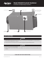
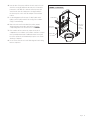
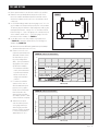
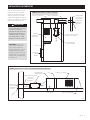
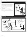
MOUNTING BRACKETS WIRE ENTRY LOCATION
INTEGRAL PRESSURE
PORTS (PORT ON INLET
SIDE NOT SHOWN)
OVAL OUTLET COLLAR
FOR 6" DIAMETER DUCT
6" DIAMETER
INLET COLLAR
ACCESS SCREWS MOTOR SPEED CONTROL
Model 8144NC Fresh Air Ventilator
Installation and Operating Instructions
10012276 B2207269A 4.18
English 1

INTRODUCTION AND COMPLIANCE STATEMENT
The Model 8144NC Fresh Air Ventilator is designed to economically bring in precisely the right amount of fresh air into today’s efficiently designed
homes and apartments. Duct the inlet of the ventilator to an outdoor air intake and the outlet to the return side of the HVAC system or into a
mechanical closet, then set the desired flow.
When properly installed and controlled, the Model 8144NC will meet the mechanical ventilation requirements of:
Energy Star Certified Homes Version 3
EPA Indoor airPLUS Version 1
2012/2015 International Residential Code (IRC)
2012/2015 International Energy Conservation Code (IECC)
2012/2015 International Mechanical Code (IMC)
California Energy Commission Title 24
TABLE OF CONTENTS
Safety Instructions ...............................................1
Introduction and Compliance Statement ...........................2
Specifications ...................................................3
Mount the Ventilator .............................................3
Wiring & Electrical Specifications ..................................4
Mount Intake Hood ..............................................6
Install Ductwork .................................................7
Wiring to External Controls .......................................8
Test and Setting .................................................9
Filter Cleaning..................................................10
Internal Schematic ..............................................10
Limited Warranty ................................................11
2 English

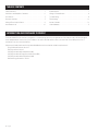
SPECIFICATIONS
Airflow: 20-160 CFM
Filter: MERV 6 washable
3 1/8"
2 7/16"
13 1/16"
15 3/4"
18 1/8"
10 1/4"
10 3/4"
10 1/4"
90-2312
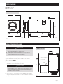
FIGURE 1 – DIMENSIONS (INCHES)
9" MIN
CLEARANCE FOR FILTER
FILTER
WIRING ACCESS
OPENING – BOTH
SIDES OF HOUSING
90-2313
FIGURE 2 – LOCATION CLEARANCES
MOUNT THE VENTILATOR
CAUTION
1. Mount the blower with the lowest, exposed moving parts at least 8
feet (2.4 m) above floor or grade level.
2. Mount the blower at least 3.3 feet (1.0 m) from an accessible
opening of the duct.
The ventilator can be mounted in any orientation. Avoid locations that
block wiring access openings in the housing and ensure that location allows
sufficient clearance for filter maintenance and service. See FIGURE 2.
1. Install the mounting brackets in the designated holes in the housing
using the supplied #8 x 1/2" screws.
CAUTION
Screwing the brackets or any other hardware into any other
location but the designated mount location may cause damage and
invalidate the warranty.
2. Secure the unit to joists or a strong platform (do not install directly to
drywall only as the ventilator weighs approximately 20 pounds) using
the #10 x 3/4" screws provided.
English 3

WIRING & ELECTRICAL SPECIFICATIONS
WARNING
ELECTRICAL SHOCK HAZARD: 115-volts may cause serious injury or death from electrical shock. Disconnect and tag electrical service before
starting installation or field-service. Leave electrical service disconnected until installation or field-service is complete.
ELECTRICAL SHOCK HAZARD: An interrupted or broken ground may cause property damage, serious injury or death should an electrical fault
occur. The cabinet must be grounded in accordance with national and local codes.
FIRE HAZARD: Use of improper wire may cause serious injury, property damage or death due to fire. Do not use aluminum wire for electrical
service to the ventilator. Use only copper wire.
Input Voltage: 115 VAC, 60Hz, single-phase
Maximum Operating Current: 0.60 A
The Model 8144NC Fresh Air Ventilator must be hard wired. An electrical disconnect switch can be installed as needed to comply with appropriate
codes or ordinances. The ON/OFF switch on the ventilator interrupts the 115VAC service to the blower of the ventilator, but does not disconnect the
power supply input to the unit.
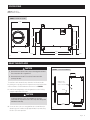
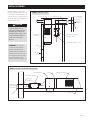
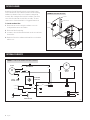
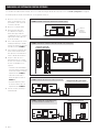
VENTILATOR
MECHANICAL VENTILATION
DISCONNECT SWITCH
120 VAC
SERVICE
MOTOR SPEED
ADJUSTMENT KNOB
COVER RETAINING SCREW
COVER
COVER INSULATION
ELECTRICAL COVER RETAINING SCREW
ELECTRICAL COVER
AIRFLOW TEST PORT
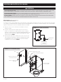
FIGURE 3 – ELECTRICAL SERVICE TO VENTILATOR
FIGURE 4 – ELECTRICAL COMPARTMENT ACCESS
90-2313
1. Disconnect electrical service at the fuse or circuit breaker that will be
serving the ventilator.
2. Run electrical service to the ventilator. Install an electrical disconnect
switch located as required by national and local code and label it as
a “MECHANICAL VENTILATION” switch to differentiate it from other
switches. A label is provided inside the ventilator carton. See FIGURE 3.
3. Remove the motor speed adjustment knob and take off the cover by
removing the two retaining screws. Remove the cover insulation to
expose the electrical compartment cover then remove the retaining
screw to take off the electrical compartment cover. See FIGURE 4.
4 English

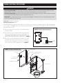
POWER CABLE
OR CONDUIT
POWER WIRES
KNOCKOUT
FOR WIRE
ENTRY
THIS SIDE
WIRE ENTRY
HOLE PLUG
90-2319
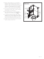
FIGURE 5 – POWER WIRING
4. Insert the wires of the power cable into the wire entry hole on the
side of the housing. By default the wire entry hole is nearest the
power wires on the PCB. If it is desired to have the power wires
enter from the other side, simply remove the plug installed in
the wire entry hole on the other side and place it in the default
location.
5. Use a bushing approved for the type of cable/conduit used to
rigidly secure the cable/conduit to the housing of the ventilator
using 1/2" nominal fittings.
6. Remove the wire nuts from the black (line), white (neutral)
and ground (green) power wires and connect each to the
corresponding wires in the electrical service. See FIGURE 5.
7. If the ventilator will run continuously, replace the electrical
compartment cover, ventilator cover insulation, ventilator cover and
motor speed adjustment knob. If additional external controls will
be used to operate the unit intermittently, keep the cover off until
all wiring is completed.
8. Do not restore electrical service until all ducting and control wiring
has been completed.
English 5

MOUNT INTAKE HOOD
Install a weather tight hood with a bird screen.
Cut a hole in the exterior wall that is large enough to fit 6" insulated flexible duct through with minimal compression of the insulation. Pull the duct
through the hole and attach the flex duct to the collar of the hood. Use metal foil tape or a plastic zip-tie to secure the duct to the collar. Pull the
insulation and vapor barrier over the duct and tape it to the collar.
IMPORTANT: The end of the insulation must be sealed to prevent condensation from forming inside the insulation. If a plastic zip-tie is used to
secure the insulation to the hood collar, also tape the end to seal it against condensation problems.
Press the hood against the outside wall and secure in place with screws; seal around the perimeter of the hood with caulk.
6 English

RETURN
GRILLE
FURNAC
E/AIR
HANDLER
FILTER
SUPPLY DUCT FRESH AIR DUCT OUTSIDE WALL
OR OUTSIDE
AIR SHAFT
FRESH AIR
INTAKE HOOD
MODEL 8144NC VENTILATOR
MOUNTED TO WALL
FRESH AIR DISCHARGE TO CLOSET
MODEL 8144NC VENTILATOR
FRESH AIR
INTAKE DUCT
RETURN MIXING BOX FILTER FURNACE/AIR HANDLER
AIR FLOW
FRESH AIR
INTAKE HOOD
WITH SCREEN
FRESH AIR
SUPPLY DUCT
90-2295
90-2295
FIGURE 6 – DUCTING TO CLOSET
FIGURE 7 – DUCTING TO RETURN SIDE OF HVAC SYSTEM
INSTALL DUCTWORK
Install 6" diameter insulated duct
from the round inlet collar of the unit
to the intake hood and from the oval
outlet of the unit to either the return
side of the HVAC system ductwork, or
to a mechanical closet.
CAUTION
Freezing temperatures can
cause pipes to rupture. Do not
discharge outdoor air directly
at a pipe or water heater, or any
other item at which unheated
outdoor air should not be
directed.
IMPORTANT: The end of the
insulation must be sealed to
prevent condensation from
forming inside the insulation. If
a plastic zip-tie is used to secure
the insulation to the hood collar,
also tape the end to seal it
against condensation problems.
English 7

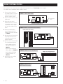
WIRING TO EXTERNAL CONTROLS
If the ventilator is to run continuously, then no additional wiring is required – go to Test and Setting section on page 9.
The ventilator can run intermittently with a ventilation controller.
N
L
120 VAC
CON3
CON2
CON1
8144NC CIRCUIT BOARD
MODEL 8620/8620W THERMOSTAT
C I2
I1 Y
O/B RC
RG
Y2 W2
L T2
T1
S1
S2
W
N
L
120 VAC
CON3
CON2
CON1
8144NC CIRCUIT BOARD
MODEL 8120X DIGITAL VENTILATION CONTROL
R
C
Y
W
O
Gs
Gh
VENT
ODT
FIGURE 10 – WIRING TO 8620/8620W THERMOSTAT
FIGURE 11 – WIRING TO 8120X
DIGITAL VENTILATION CONTROL
N
L
120 VAC
CON3
CON2
CON1
8144NC CIRCUIT BOARD AS SHIPPED
PRE-INSTALLED
JUMPER
N
L
120 VAC
CON3
CON2
CON1
8144NC CIRCUIT BOARD
CONTROL MODULE OF IAQ CONTROL
FIGURE 8 – CONTROL WIRING JUMPER
FIGURE 9 – WIRING TO 8910/8910W/8920W IAQ CONTROL
1. Disconnect electrical service to
the ventilator at the fuse or circuit
breaker that feeds the circuit to
which the ventilator is wired.
2. Disconnect electrical service to the
HVAC system.
3. Remove the motor speed
adjustment knob, the cover and
cover insulation, and the electrical
compartment cover (see Figure
4) to access the ventilator circuit
board.
4. Cut the pre-installed jumper
wire in half and strip of 1/2" of
insulation off the end of each wire.
See FIGURE 8.
5. Run external control wires through
the opening on the side of the
housing opposite where power
wiring was installed.
6. Wire as shown for control selected.
The recommended controls are:
• Aprilaire IAQ Control Model
8910, 8910W or 8920W. See
FIGURE 9.
• Aprilaire Thermostat Models
8620 or 8620W. See FIGURE 10.
• Aprilaire Model 8120X Digital
Ventilation Controller. See
FIGURE 11.
7. Restore power to the ventilator
and the HVAC system.
8 English

TEST AND SETTING
1. Restore power and turn on any disconnect switch to the ventilator
2. Rotate the motor speed adjustment just past the on/off click to
turn on the ventilator at maximum speed. If an external control is
wired to the ventilator, turn the control on so the ventilator can run
continuously.
3. Use 1/4" flexible tubing to attach a pressure gauge (set to " w.c. or in.
w.g. or inH2O) to the inlet and outlet pressure ports on the ventilator.
The pressure gauge should have as small a range as possible to get a
meaningful measurement – a range of 1.0" w.c. should be sufficient.
Connect the high or “+” port of the gauge to the outlet pressure port
on the ventilator, and the low or “–” port of the gauge to the inlet
pressure port on the ventilator. See FIGURE 12.
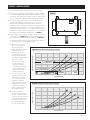
4. Use the label on the cover of the ventilator, or the blank curves
in FIGURE 13B, to determine airflow delivery. The following is an
example using FIGURE 13A:
a. Measure the pressure differential at maximum speed (example
assumes measured pressure is 0.35" w.c.).
b. Find the circle on the curve
nearest the measured pressure
differential. Extend a vertical
line down from the circle to
the corresponding airflow
(CFM) – this is the maximum
speed airflow of the system
(145 CFM in the example).
• For intermittent ventilation
controls, this measurement
is the delivered ventilation
airflow. Use this value in
setting up the ventilation
controller.
c. For continuous ventilation
systems, use the curve on
which the maximum speed
pressure circle is located to
find the Pressure Differential
that corresponds to the
desired continuous airflow
(the example assumes 75 CFM
continuous airflow is required).
d. Adjust the motor speed
controller until the pressure
on the gauge matches the
desired continuous airflow
pressure (75 CFM corresponds
to a Pressure Differential of
approximately 0.10" w.c.).
0
0.1
0.2
0.3
0.4
0.5
0.6
0 20 40 60 80 100 120 140
160
PRESSURE DIFFERENTIAL (inH2O)
AIRFLOW (CFM)
4a
4b
4c
4d
0.35" W.C. @ MAX SPEED
0.10" W.C. @ DESIRED
CONTINUOUS AIRFLOW
75 CFM
CONTINUOUS
145 CFM @
MAX SPEED
0
0.1
0.2
0.3
0.4
0.5
0.6
0 20 40 60 80 100 120 140
160
PRESSURE DROP (inH2O)
AIRFLOW (CFM)
FIGURE 13A – AIRFLOW SETTING EXAMPLE
FIGURE 13B – AIRFLOW SETTING CURVES
INLET
OUTLET
90-2315
FIGURE 12
English 9

FILTER CLEANING
Normally the fresh air filter will need to be removed and cleaned
every six months, but check it after the first three months following
installation to determine if more or less frequent cleaning will be
necessary. After cleaning the filter inside the ventilator, clean off the
screen at the fresh air intake hood (if safely accessible). The most
common cause of reduced ventilation is a clogged air intake hood.
To clean the ventilator filter:
1. Remove the two screws securing the ventilator cover to the
housing and then remove the insulation.
2. Remove the filter from housing.
3. Use water to rinse the filter and then shake out the excess moisture
from the filter.
4. Replace the filter in the ventilator and reinstall the cover insulation
and the cover.
KNOB
SCREW
COVER
INSULATION
FILTER
90-2316
FIGURE 14 – REMOVING THE FILTER
INTERNAL SCHEMATIC
M
RED
BLOWER
RUN CAPACITOR
GRN
BLK
GRN
L2-WHT
L1-BLK
CHASSIS GROUND
GND
CHASSIS
GROUND
BLK
WHT
M
YLW
YLW
DAMPER
MOTOR
N
L
120 VAC
CON3
CON2
CON3
POWER PCB ASSEMBLY
BLU
BRN
YLW
WHT
BLU
BLU
MOTOR SPEED
CONTROLLER
90-2317
FIGURE 15 – MODEL 8144NC INTERNAL ELECTRICAL SCHEMATIC
10 English

LIMITED WARRANTY
Your Research Products Corporation Aprilaire® Fresh Air Ventilator is expressly warranted for five (5) years from date of installation to be free from defects in materials or workmanship.
Research Products Corporation’s exclusive obligation under this warranty shall be to supply, without charge, a replacement for any component which is found to be defective within such
five (5) year period and which is returned not later than thirty (30) days after said five (5) year period by you to either your original supplier or to Research Products Corporation, Madison,
Wisconsin 53701, together with the model number and installation date of the ventilator.
THIS WARRANTY SHALL NOT OBLIGATE RESEARCH PRODUCTS CORPORATION FOR ANY LABOR COSTS AND SHALL NOT APPLY TO DEFECTS IN WORKMANSHIP OR MATERIALS
FURNISHED BY YOUR INSTALLER AS CONTRASTED TO DEFECTS IN THE VENTILATOR ITSELF.
IMPLIED WARRANTIES OF MERCHANTABILITY OR FITNESS FOR A PARTICULAR PURPOSE SHALL BE LIMITED IN DURATION TO THE AFORESAID FIVE YEAR PERIOD. RESEARCH PRODUCTS
CORPORATION’S LIABILITY FOR INCIDENTAL OR CONSEQUENTIAL DAMAGES, OTHER THAN DAMAGES FOR PERSONAL INJURIES, RESULTING FROM ANY BREACH OF THE AFORESAID
IMPLIED WARRANTIES OR THE ABOVE LIMITED WARRANTY IS EXPRESSLY EXCLUDED. THIS LIMITED WARRANTY IS VOID IF DEFECTS(S) RESULT FROM FAILURE TO HAVE THIS UNIT
INSTALLED BY A QUALIFIED HEATING AND AIR CONDITIONING CONTRACTOR. IF THE LIMITED WARRANTY IS VOID DUE TO FAILURE TO USE A QUALIFIED CONTRACTOR, ALL DISCLAIMERS
OF IMPLIED WARRANTIES SHALL BE EFFECTIVE UPON INSTALLATION.
Some states do not allow limitations on how long an implied warranty lasts or the exclusion or limitation of incidental or consequential damages so the above exclusion or limitations may
not apply to you.
This warranty gives you specific legal rights and you may also have other rights which vary from state to state.
WARRANTY REGISTRATION
Visit us online at www.aprilaire.com to register your Aprilaire product. If you do not have online access, please mail a postcard with your name, address, phone number, email address, product
purchased, model number, date of purchase, and dealer name and address to: Research Products Corporation, P.O. Box 1467, Madison, WI 53701.
Your warranty registration information will not be sold or shared outside of this company.
English 11

AprilairePartners.com
P.O. Box 1467
Madison, WI 53701-1467
800.334.6011 F: 608.257.4357
Printed in USA
©2018 Aprilaire – Division of Research Products Corporation
12 English

INSTRUCCIONES DE SEGURIDAD
ADVERTENCIA
1. El voltaje de 120V puede provocar lesiones graves por descarga eléctrica. Antes de comenzar con el proceso de instalación o de mantenimiento, desconecte
el artefacto. Deje el artefacto desconectado hasta que se complete la instalación.
2. Los bordes filosos pueden causar lesiones graves por cortes. Se debe tener precaución al cortar las aberturas de la cámara y manipular los conductos.
PRECAUCIÓN
1. Lea las instrucciones antes de comenzar con la instalación.
2. Si se instala el artefacto de manera incorrecta puede causar daños a la propiedad o lesiones. Un técnico calificado debe realizar la instalación, el servicio y el
mantenimiento del artefacto.
LEA Y CONSERVE ESTAS INSTRUCCIONES
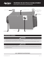
SOPORTES DE MONTAJE UBICACIÓN DE ENTRADA DE LOS CABLES
PUERTOS DE PRESIÓN
INTEGRAL (NO SE MUESTRA
EL PUERTO DEL LADO DE
LA ENTRADA)
ANILLO DE SALIDA
OVALADO PARA CONDUCTO
DE 6IN DE DIÁMETRO
ANILLO DE
ENTRADA DE 6IN
DE DIÁMETRO
TORNILLOS DE ACCESO CONTROL DE VELOCIDAD DEL MOTOR
Ventilador de aire fresco modelo 8144NC
Instrucciones de instalación y funcionamiento
10012276 B2207269A 4.18
Español 1

INTRODUCCIÓN Y DECLARACIÓN DE CUMPLIMIENTO
El ventilador de aire fresco modelo 8144NC está diseñado para incorporar de forma económica la cantidad precisa de aire fresco a las viviendas actuales diseñadas
eficientemente. Conecte la entrada del ventilador a una entrada de aire exterior y la salida al lateral de retorno del sistema de HVAC o dentro de un armario mecánico
y, luego, configure el flujo deseado.
Si se instala y se controla de manera adecuada, el modelo 8144NC cumplirá con los siguientes requisitos de los sistemas de ventilación mecánica:
Energy Star Certified Homes, versión 3
Indoor airPLUS de la EPA, versión 1
Código Residencial Internacional (International Residential Code, IRC) 2012/2015
Código Internacional de Conservación de Energía (International Energy Conservation Code, IECC) 2012/2015
Código mecánico internacional (International Mechanical Code, IMC) 2012/2015
Título 24 de la Comisión de Energía de California
ÍNDICE
Instrucciones de seguridad .............................................. 1
Introducción y declaración de cumplimiento ...............................2
Especificaciones ........................................................3
Instalación del ventilador ...............................................3
Especificaciones eléctricas y de cableado..................................4
Instalación del extractor de admisión .....................................6
Instalación de los conductos .............................................7
Cableado a los sistemas de control externos...............................8
Pruebas y configuración .................................................9
Limpieza del filtro......................................................10
Esquema interno ......................................................10
Garantía limitada .......................................................11
2 Español

ESPECIFICACIONES
Flujo de aire: 20-160CFM
Filtro: MERV 6, lavable
3 1/8"
2 7/16"
13 1/16"
15 3/4"
18 1/8"
10 1/4"
10 3/4"
10 1/4"
90-2312
FIGURA1: DIMENSIONES (PULGADAS)
ESPACIO MÍNIMO DE
9IN PARA EL FILTRO
FILTRO
ABERTURA DE
ACCESO AL CABLEADO:
AMBOS LADOS
DE LA CARCASA
90-2313
FIGURA2: SEPARACIONES
INSTALACIÓN DEL VENTILADOR
PRECAUCIÓN
1. Con la menor cantidad de piezas móviles expuestas, instale el soplador al
menos a 8pies (2.4m) del piso o del nivel del suelo.
2. Instale el soplador a una distancia mínima de 3.3pies (1.0m) de una
abertura desde la que se pueda acceder al conducto.
El ventilador se puede instalar en cualquier orientación. Evite instalar el ventilador
en lugares que bloqueen las aberturas de acceso al cableado en la carcasa y
asegúrese de tener espacio suficiente para realizar el mantenimiento del ventilador
y del filtro. Consulte la FIGURA2.
1. Utilice los tornillos n.°8 x 1/2in que se proporcionan para instalar los soportes
de montaje en los orificios designados en la carcasa.
PRECAUCIÓN
Puede atornillar los soportes o cualquier otro accesorio de montaje en otra
ubicación, pero la ubicación que designe para realizar la instalación puede
causar daños e invalidar la garantía.
2. Utilice los tornillos n.°10 x 3/4in que se proporcionan para sujetar la unidad a
las vigas o a una plataforma resistente (no lo instale directamente en paneles de
yeso ya que el ventilador pesa aproximadamente 20 libras).
Español 3

ESPECIFICACIONES ELÉCTRICAS Y DE CABLEADO
ADVERTENCIA
PELIGRO DE DESCARGA ELÉCTRICA: El voltaje de 115V puede provocar lesiones graves o muerte por descarga eléctrica. Desconecte y etiquete el servicio eléctrico
antes de realizar la instalación o el mantenimiento externo. Deje el artefacto desconectado hasta que complete la instalación o el mantenimiento externo.
PELIGRO DE DESCARGA ELÉCTRICA: Una conexión a tierra interrumpida o defectuosa puede provocar daños a la propiedad, lesiones graves o la muerte si se
produce una falla eléctrica. El gabinete se debe conectar a tierra de acuerdo con los códigos nacionales y locales.
PELIGRO DE INCENDIO: Si utiliza un cable incorrecto puede provocar lesiones graves, daños a la propiedad o la muerte causados por un incendio. No utilice
cables de aluminio para conectar el servicio de electricidad al ventilador. Utilice solamente cables de cobre.
Voltaje de entrada: 115VCA, 60Hz, fase única
Corriente máxima de funcionamiento: 0.60A
El ventilador de aire fresco modelo 8144NC se debe conectar firmemente. Se puede instalar un interruptor de desconexión eléctrica según sea necesario para cumplir
con los códigos y las ordenanzas adecuados. El interruptor ON/OFF (Encendido/apagado) que se encuentra en el ventilador interrumpe el servicio de 115VCA para el
soplador del ventilador, pero no desconecta la entrada de alimentación a la unidad.
VENTILADOR
INTERRUPTOR DE
DESCONEXIÓN DEL
SISTEMA DE
VENTILACIÓN MECÁNICO
MANTENIMIENTO
DE 120VCA
PERILLA DE AJUSTE DE LA
VELOCIDAD DEL MOTOR
TORNILLO DE RETENCIÓN
DE LA TAPA
TAPA
AISLAMIENTO DE LA TAPA
TORNILLO DE RETENCIÓN DE LA TAPA
TAPA DEL COMPARTIMENTO ELÉCTRICO
PUERTO DE PRUEBA
DEL FLUJO DE AIRE
FIGURA 3: SERVICIO ELÉCTRICO DEL VENTILADOR
FIGURA 4: ACCESO AL COMPARTIMIENTO ELÉCTRICO
90-2313
1. Desconecte el servicio eléctrico del fusible o del interruptor de circuito que
alimenta al ventilador.
2. Encienda el ventilador. Instale un interruptor de desconexión eléctrico de
acuerdo con los requisitos de los códigos nacionales y locales y coloque una
etiqueta en el interruptor que diga “SISTEMA DE VENTILACIÓN MECÁNICO” para
diferenciarlo de otros interruptores. Se proporciona una etiqueta en la caja del
ventilador. Consulte la FIGURA3.
3. Retire la perilla de ajuste de la velocidad del motor y retire los dos tornillos de
retención para retirar la tapa. Retire el aislante de la tapa para mostrar la tapa
del compartimento eléctrico y luego retire el tornillo para retirar la tapa del
compartimento eléctrico. Consulte la FIGURA4.
4 Español

CABLE O
CONDUCTO DE
ALIMENTACIÓN
CABLES DE
ALIMENTACIÓN
TROQUEL
PARA LA
ENTRADA
DE CABLES
POR ESTE
LADO
TAPA DEL
ORIFICIO
PARA LA
ENTRADA
DE CABLES
90-2319
FIGURA 5: CABLEADO
4. Introduzca los cables de alimentación en el orificio de entrada de los
cables que se encuentra al costado de la carcasa. Por defecto, el orificio
de entrada de los cables se encuentra más cerca de los cables de
alimentación en el Tablero de circuito impreso (Printed Circuit Board, PCB).
Si desea que los cables de alimentación ingresen por el otro costado,
simplemente retire el enchufe instalado en el orificio de entrada de los
cables en el otro costado y colóquelo en la ubicación predeterminada.
5. Utilice un casquillo que sea adecuado para el tipo de cable o conducto
utilizado para sujetar con firmeza el cable o el conducto a la carcasa del
ventilador usando accesorios nominales de 1/2in.
6. Retire los empalmes de plástico de los cables negro (línea), blanco
(neutro) y de conexión a tierra (verde) y conecte cada uno a los cables
correspondientes en el servicio eléctrico. Consulte la FIGURA5.
7. Si el ventilador funcionará de manera constante, reemplace la tapa del
compartimiento eléctrico, el aislante de la tapa del ventilador, la tapa del
ventilador y la perilla de ajuste de la velocidad del motor. Si utilizará sistemas
de control externos adicionales para que la unidad funcione de forma
intermitente, retire la tapa hasta que realice todo el cableado por completo.
8. No restablezca el servicio eléctrico hasta que finalice de colocar todos los
conductos y el cableado del sistema de control.
Español 5

INSTALACIÓN DEL EXTRACTOR DE ADMISIÓN
Instale un extractor hermético con una malla contra pájaros.
Haga un agujero en la pared exterior que sea lo suficientemente grande como para que ingrese un conducto flexible aislado de 6in con una compresión mínima del
aislamiento. Pase el conducto a través del orificio y conecte el conducto flexible al anillo del extractor. Utilice cinta adhesiva metálica o una abrazadera de plástico para
fijar el conducto al anillo. Tire de la barrera de vapor y del aislamiento sobre el conducto y péguela al anillo.
IMPORTANTE: se debe sellar el final del aislamiento para evitar que se produzca condensación dentro del aislamiento. Si se utiliza una abrazadera de plástico
para asegurar el aislamiento al anillo del extractor, también coloque cinta al final para sellar y evitar problemas de condensación.
Presione el extractor contra la pared exterior y ajústelo en su lugar con los tornillos; selle todo el perímetro del extractor con sellador.
6 Español

REJILLA DEL
AIRE DE
RETORNO
SISTEMA DE
CALEFACCIÓN/
CLIMATIZADOR
FILTRO
CONDUCTO DE SUMINISTRO CONDUCTO DE AIRE FRESCO PARED EXTERIOR
O CONDUCTO DE
AIRE EXTERIOR
EXTRACTOR DE
ADMISIÓN DE
AIRE FRESCO
VENTILADOR MODELO 8144NC
INSTALADO EN LA PARED
DESCARGA DE AIRE
FRESCO AL ARMARIO
VENTILADOR MODELO 8144NC
CONDUCTO DE
ADMISIÓN DE
AIRE FRESCO
CAJA DE MEZCLA DE
AIRE DE RETORNO
FILTRO CLIMATIZADOR CON FILTRO
FLUJO DE AIRE
EXTRACTOR
DE ADMISIÓN
DE AIRE FRESCO
CON MALLA
AIRE FRESCO
CONDUCTO DE SUMINISTRO
90-2295
90-2295
FIGURA 6: INSTALACIÓN DE LOS CONDUCTOS AL ARMARIO
FIGURA 7: INSTALACIÓN DE LOS CONDUCTOS AL LATERAL DE RETORNO DEL SISTEMA DE HVAC
INSTALACIÓN DE LOS CONDUCTOS
Instale un conducto aislado de 6in de
diámetro desde el anillo de entrada
redondo de la unidad al extractor de
admisión y desde el anillo de salida
ovalado de la unidad hasta el lateral de
retorno de los conductos del sistema de
HVAC o hasta un armario mecánico.
PRECAUCIÓN
Las temperaturas bajo cero pueden
provocar que las tuberías se
rompan. No descargue aire exterior
directamente a una tubería o a un
calentador de agua, o a cualquier
otro elemento al que no se deba
dirigir el aire exterior sin calentar.
IMPORTANTE: se debe sellar el
final del aislamiento para evitar
que se produzca condensación
dentro del aislamiento. Si se utiliza
una abrazadera de plástico para
asegurar el aislamiento al anillo del
extractor, también coloque cinta al
final para sellar y evitar problemas
de condensación.
Español 7

CABLEADO A LOS SISTEMAS DE CONTROL EXTERNOS
Si el ventilador funcionará de manera constante, entonces no se debe realizar ningún cableado adicional, diríjase a la sección Pruebas y configuración en la página 9.
El ventilador puede funcionar de forma intermitente con un regulador de ventilación.
N
L
120 VCA
CON3
CON2
CON1
TABLERO DE CIRCUITOS DEL MODELO 8144NC
TERMOSTATO MODELO 8620/8620W
C I2
I1 Y
O/B RC
RG
Y2 W2
L T2
T1
S1
S2
W
N
L
120 VCA
CON3
CON2
CON1
TABLERO DE CIRCUITOS DEL MODELO 8144NC
SISTEMA DE CONTROL DIGITAL DEL SISTEMA
DE VENTILACIÓN MODELO 8120X
R
C
Y
W
O
Gs
Gh
VENT
ODT
FIGURA 10: CABLEADO DEL TERMOSTATO MODELOS 8620/8620W
FIGURA 11: CABLEADO DEL CONTROLADOR DIGITAL
DEL SISTEMA DE VENTILACIÓN MODELO 8120X
N
L
120 VCA
CON3
CON2
CON1
TABLERO DE CIRCUITO DEL MODELO 8144NC, TAL COMO SE ENVIÓ
PUENTE DE
CONEXIÓN
INSTALADO
PREVIAMENTE
N
L
120 VCA
CON3
CON2
CON1
TABLERO DE CIRCUITOS DEL MODELO 8144NC
MÓDULO DE CONTROL DEL
SISTEMA DE CONTROL DE IAQ
FIGURA 8: PUENTE DE CONEXIÓN DEL CABLEADO DEL SISTEMA DE CONTROL
FIGURA 9: CABLEADO DEL SISTEMA DE CONTROL DE IAQ MODELOS 8910/8910W/8920W
1. Desconecte el servicio eléctrico del
fusible o del interruptor de circuito
que alimenta el circuito al que está
conectado el ventilador.
2. Desconecte el sistema de HVAC.
3. Retire la perilla de ajuste de la
velocidad del motor, la tapa y el
aislante de la tapa y la tapa del
compartimiento eléctrico (consulte lar
figura 4) para acceder al tablero de
circuito del ventilador.
4. Corte el cable del puente de conexión
instalado previamente por la mitad y
retire 1/2in de aislante del extremo de
cada cable. Consulte la FIGURA8.
5. Pase los cables del sistema de control
externo a través de la abertura del
lado opuesto de la carcasa donde se
instaló el cableado de alimentación.
6. Coloque los cables tal como se
muestra de acuerdo con el sistema
de control seleccionado. Los sistemas
de control recomendados son los
siguientes:
• Sistema de control de Calidad del
aire interior (Indoor Air Quality, IAQ)
modelos 8910, 8910W o 8920W de
Aprilaire Consulte la FIGURA9.
• Termostatos modelos 8620 o
8620W de Aprilaire. Consulte la
FIGURA10.
• Controlador digital del sistema
de ventilación modelo 8120X de
Aprilaire Consulte la FIGURA11.
7. Vuelva a conectar el ventilador y el
sistema de HVAC.
8 Español

PRUEBAS Y CONFIGURACIÓN
1. Conecte y encienda cualquier interruptor de desconexión al ventilador.
2. Gire el ajuste de velocidad del motor justo después de escuchar el sonido de
clic de encendido/apagado para encender el ventilador a máxima velocidad. Si
un sistema de control externo está conectado al ventilador, encienda el sistema
de control de modo que el ventilador pueda funcionar de forma constante.
3. Utilice un tubo flexible de 1/4in para conectar un indicador de presión
(configurado en pulgadas de columna de agua o in w.g. o in H2O) a los
puertos de presión de entrada y salida del ventilador. El indicador de
presión debe contar con un rango lo más pequeño posible para obtener una
medición significativa: un rango de 1.0in de columna de agua debería ser
suficiente. Conecte el puerto superior o “+” del indicador de presión al puerto
de presión de la salida del ventilador y el puerto inferior o “-” del indicador al
puerto de presión de la entrada del ventilador. Consulte la FIGURA12.
4. Consulte la etiqueta que se encuentra en la tapa del ventilador, o las curvas con
círculos en blanco en la FIGURA 13B, para determinar la distribución del flujo de
aire. A continuación se presenta un ejemplo de acuerdo con la FIGURA 13A:
a. Mida el diferencial de presión a máxima velocidad (según el ejemplo, la
medida de presión es 0.35in de columna de agua).
b. Ubique el círculo en la curva
que se encuentre más cerca
del diferencial de presión
medido. Trace una línea vertical
hacia abajo desde el círculo
hasta el valor de flujo de aire
correspondiente (CFM): ese valor
será el flujo de aire a máxima
velocidad del sistema (145CFM de
acuerdo con el ejemplo).
• En el caso de los sistemas
de control de ventilación
intermitente, esta medida
corresponde al flujo de aire de
ventilación distribuido. Utilice
este valor para configurar el
regulador de ventilación.
c. En el caso de los sistemas de
ventilación constante, utilice la
curva en la que se encuentra el
círculo con el valor de presión
de máxima velocidad para
calcular el diferencial de presión
correspondiente al flujo de aire
constante deseado (según el
ejemplo, se requiere un flujo de
aire constante de 75CFM).
d. Configure el regulador de
velocidad del motor hasta que la
presión en el indicador de presión
coincida con la presión del flujo de
aire constante deseado (75CFM
corresponde a un diferencial de
presión de aproximadamente
0.10in de columna de agua).
0
0.1
0.2
0.3
0.4
0.5
0.6
0 20 40 60 80 100 120 140
160
DIFERENCIAL DE PRESIÓN (inH2O)
FLUJO DE AIRE (CFM)
4a
4b
4c
4d
0.35. COLUMNA DE AGUA
A VELOCIDAD MÁXIMA
0.10. COLUMNA DE AGUA A FLUJO
DE AIRE CONSTANTE DESEADO
75CFM
CONSTANTES
145CFM A
VELOCIDAD
MÁXIMA
0
0.1
0.2
0.3
0.4
0.5
0.6
0 20 40 60 80 100 120 140
160
CAÍDA DE PRESIÓN (inH2O)
FLUJO DE AIRE (CFM)
FIGURA 13A: EJEMPLO DE CONFIGURACIÓN DEL FLUJO DE AIRE
FIGURA 13B: CURVAS DE CONFIGURACIÓN DEL FLUJO DE AIRE
ENTRADA
SALIDA
90-2315
FIGURA12
Español 9

LIMPIEZA DEL FILTRO
Por lo general, el filtro de aire fresco se debe retirar y limpiar cada seis
meses, pero debe verificarlo luego de los primeros tres meses posteriores a
la instalación para determinar si es necesario realizar una limpieza con mayor
o menor frecuencia. Una vez que limpie el filtro dentro del ventilador, limpie
la malla en el extractor de admisión de aire fresco (si se puede acceder de
manera segura). La causa más común por la cual se reduce la capacidad de
ventilación es debido a que el extractor de admisión de aire está obstruido.
Para limpiar el filtro del ventilador:
1. Retire los dos tornillos que sujetan la tapa del ventilador a la carcasa y
luego retire el aislante.
2. Retire el filtro de la carcasa.
3. Enjuague el filtro y luego sacuda el exceso de humedad del filtro.
4. Reemplace el filtro en el ventilador y vuelva a colocar el aislante de la tapa
y la tapa.
PERILLA
TORNILLO
TAPA
AISLAMIENTO
FILTRO
90-2316
FIGURA 14: CÓMO RETIRAR EL FILTRO
ESQUEMA INTERNO
M
ROJO
SOPLADOR
CONDENSADOR DE
FUNCIONAMIENTO
VERDE
NEGRO
VERDE
L2-BLANCO
L1-NEGRO
CONEXIÓN A
TIERRA DEL CHASIS
CONEXIÓN
A TIERRA
CONEXIÓN
A TIERRA
DEL CHASIS
NEGRO
BLANCO
M
AMARILLO
AMARILLO
REGULADOR
DEL MOTOR
N
L
120 VCA
CON3
CON2
CON3
TABLERO DE CIRCUITO IMPRESO DE CONTROL DE POTENCIA
AZUL
MARRÓN
AMARILLO
BLANCO
AZUL
AZUL
CONTROLADOR DE
VELOCIDAD DEL MOTOR
90-2317
FIGURA 15: ESQUEMA ELÉCTRICO INTERNO DEL MODELO 8144NC
10 Español

GARANTÍA LIMITADA
El ventilador de aire fresco de Research Products Corporation de Aprilaire® cuenta con una garantía de cinco (5) años a partir de la fecha de instalación que cubre defectos materiales o de mano de obra.
La obligación exclusiva de Research Products Corporation bajo esta garantía es la de suministrar, sin cargo, un repuesto para cualquier pieza que esté dañada dentro del período de los cinco (5) años mencionado y
usted o su proveedor original puede devolverlo hasta treinta (30) días después del período de 5 (cinco) años a Research Products Corporation, Madison, Wisconsin 53701, junto con el número de modelo y la fecha de
instalación del ventilador.
ESTA GARANTÍA NO OBLIGA A RESEARCH PRODUCTS CORPORATION A PAGAR COSTOS DE TRABAJO Y NO APLICA PARA LOS DEFECTOS EN LA MANO DE OBRA O LOS MATERIALES PROPORCIONADOS POR SU
TÉCNICO ESPECIALISTA EN INSTALACIÓN A DIFERENCIA DE LOS DEFECTOS QUE SE ENCUENTREN EN EL VENTILADOR EN SÍ.
LAS GARANTÍAS IMPLICADAS DE COMERCIALIZACIÓN O ADAPTACIÓN PARA UN PROPÓSITO EN PARTICULAR SE LIMITARÁ A LA DURACIÓN DEL PERÍODO DE CINCO AÑOS ANTEDICHO. LA RESPONSABILIDAD DE
RESEARCH PRODUCTS CORPORATION POR DAÑOS ACCIDENTALES O CONSECUENTES, ADEMÁS DE DAÑOS POR LESIONES PERSONALES QUE RESULTEN DE CUALQUIER INCUMPLIMIENTO DE LAS GARANTÍAS
IMPLÍCITAS ANTEDICHAS O LA GARANTÍA LIMITADA ANTERIOR SE EXCLUYEN EXPRESAMENTE. SI LA INSTALACIÓN DE ESTA UNIDAD NO FUE REALIZADA POR UN TÉCNICO ESPECIALISTA EN CALEFACCIÓN Y AIRE
ACONDICIONADO CALIFICADO SE ANULA ESTA GARANTÍA LIMITADA. SI LA GARANTÍA LIMITADA SE ANULA POR NO LLAMAR A UN TÉCNICO CALIFICADO, TODOS LOS DESCARGOS DE RESPONSABILIDADES DE
LAS GARANTÍAS IMPLICADAS ENTRARÁN EN VIGOR LUEGO DE LA INSTALACIÓN.
Algunos estados no permiten limitaciones acerca de cuánto durará una garantía implícita o la exclusión o limitación de los daños accidentales o consecuentes de manera que las exclusiones y limitaciones anteriores
pueden no aplicar para usted.
Esta garantía le proporciona derechos legales específicos y también puede tener otros derechos que varían de estado a estado.
REGISTRO DE GARANTÍA
Visite nuestro sitio web en www.aprilaire.com para registrar su producto Aprilaire. Si no tiene acceso en línea, envíe una carta con su nombre, dirección, número de teléfono, producto comprado, número de modelo,
fecha de compra, y nombre del distribuidor a la siguiente dirección: Research Products Corporation, P.O. Box1467, Madison, WI 53701.
La información de registro de su garantía no se venderá ni compartirá fuera de esta compañía.
Español 11

AprilairePartners.com
P.O. Box 1467
Madison, Wisconsin 53701-1467
800.334.6011 F: 608.257.4357
Impreso en EE.UU.
©2018 Aprilaire. Una división de Research Products Corporation
12 Español
-
 1
1
-
 2
2
-
 3
3
-
 4
4
-
 5
5
-
 6
6
-
 7
7
-
 8
8
-
 9
9
-
 10
10
-
 11
11
-
 12
12
-
 13
13
-
 14
14
-
 15
15
-
 16
16
-
 17
17
-
 18
18
-
 19
19
-
 20
20
-
 21
21
-
 22
22
-
 23
23
-
 24
24


Aprilaire 8144NC El manual del propietario
- Tipo
- El manual del propietario
en otros idiomas
- English: Aprilaire 8144NC Owner's manual
Artículos relacionados
-
Aprilaire 8120X El manual del propietario
-
-
Aprilaire 8145 El manual del propietario
-
-
-
Research Products Corporation 1210D2 Manual de usuario
-
-
-
Aprilaire 6727 Guía de instalación
-