MOTO GUZZI Breva 1100 Manual de usuario
- Categoría
- Motocicletas
- Tipo
- Manual de usuario
Este manual también es adecuado para

MOTO GUZZI DESEA AGRADECERLE
por haber elegido uno de sus productos. Hemos preparado este manual para permitirle apreciar todas sus cualidades. Le aconsejamos que lea todo
su contenido antes de conducir por primera vez. Contiene información, consejos y advertencias para el uso de su vehículo; asimismo, descubrirá
características, detalles y soluciones que lo convencerán de lo acertado de su elección. Estamos seguros de que teniendo todo esto en cuenta, le
resultará fácil conocer su nuevo vehículo, el cual podrá disfrutar por mucho tiempo con total satisfacción. La presente publicación es parte integrante
del vehículo y en caso de venderlo debe ser entregada al nuevo propietario.
MOTO GUZZI WOULD LIKE TO THANK YOU
for choosing one of its products. We have drawn up this booklet to provide a comprehensive overview of your vehicle's quality features. Please read it
carefully before riding the vehicle for the first time. It contains information, tips and precautions for using your vehicle. It also describes features, details
and devices to assure you that you have made the right choice. We believe that if you follow our suggestions, you will soon get to know your new vehicle
well and will use it for a long time at full satisfaction. This booklet is an integral part of the vehicle, and should the vehicle be sold, it must be transferred
to the new owner.
Breva 850 - 1100 - 1200
Ed. 03 2007

Las instrucciones de este manual han sido preparadas principalmente para suministrar una guía simple y clara de uso; se indican también las
operaciones de mantenimiento básico y los controles periódicos que se deberán realizar en los CONCESIONARIOS o Talleres autorizados Moto
Guzzi. Además, el manual contiene las instrucciones para que pueda realizar algunas reparaciones simples. Las operaciones que no se describen
explícitamente en esta publicación requieren la disponibilidad de herramientas especiales y/o de conocimientos técnicos específicos. para su ejecución
recomendamos dirigirse a los CONCESIONARIOS o Talleres autorizados Moto Guzzi.
The instructions in this manual have been prepared to offer mainly a simple and clear guide to its use; it also describes routine maintenance procedures
and regular checks that should be carried out on the vehicle at an authorised Moto Guzzi Dealer or Workshop, The booklet also contains instructions
for simple repairs. Any operations not specifically described in this booklet require the use of special tools and/or particular technical knowledge; for
these operations, please take your vehicle to an authorised Moto Guzzi Dealer or Workshop.
2

Seguridad de las personas
El no-cumplimiento total o parcial de estas prescrip-
ciones puede comportar peligro grave para la incolu-
midad de las personas.
Personal safety
Failure to completely observe these instructions will
result in serious risk of personal injury.
Salvaguardia del ambiente
Indica el comportamiento correcto para que el uso del
vehículo no cause ningún daño a la naturaleza.
Safeguarding the environment
Sections marked with this symbol indicate the correct
use of the vehicle to prevent damaging the environ-
ment.
Integridad del vehículo
El no-cumplimiento total o parcial de estas prescrip-
ciones comporta el peligro de serios daños al vehículo
e incluso la caducidad de la garantía.
Vehicle intactness
The incomplete or non-observance of these regula-
tions leads to the risk of serious damage to the vehicle
and sometimes even the invalidity of the guarantee.
Las señales indicadas previamente son de gran im-
portancia. Sirven para evidenciar las partes del ma-
nual que requieren de más atención. Como se puede
observar, cada señal está compuesta por un símbolo
gráfico diferente, para facilitar y agilizar la búsqueda
de los temas en las diversas áreas. Antes de poner
en marcha el motor, leer atentamente este manual,
especialmente el apartado "CONDUCCIÓN SEGU-
RA". Su seguridad y la de los demás no depende
solamente de la rapidez de sus reflejos y agilidad, si-
no también del conocimiento del vehículo, de su efi-
ciencia y del conocimiento de las reglas fundamenta-
les para la CONDUCCIÓN SEGURA. Por lo tanto, le
recomendamos familiarizarse con el vehículo lo sufi-
ciente como para circular por la carretera con total
control y seguridad. IMPORTANTE Este manual se
debe considerar como parte integrante del vehículo y
debe acompañarlo en caso de venta.
The symbols illustrated above are very important.
They are used to highlight parts of the booklet that
should be read with particular care. The different sym-
bols are used to make each topic in the manual simple
and quick to locate. Before starting the engine, read
this booklet thoroughly and the "SAFE RIDING" sec-
tion in particular. Your safety as well as other's does
not only depend on the quickness of your reflexes and
agility, but also on how well you know your vehicle,
the state of maintenance of the vehicle itself and your
knowledge of the rules for SAFE RIDING. For your
safety, get to know your vehicle well so as to safely
ride and master it in road traffic IMPORTANT This
booklet is an integral part of the vehicle, and must be
handed to the new owner in the event of sale.
3

4

INDICE
INDEX
NORMAS GENERALES................................................................. 9
Introducción.............................................................................. 10
Monóxido de carbono............................................................... 10
Combustible............................................................................. 11
Componentes calientes............................................................ 12
Puesta en marcha y Conducción............................................. 12
Testigos.................................................................................... 13
Aceite motor y aceite cambio usados...................................... 14
Líquido frenos y embrague...................................................... 15
Electrolito y gas hidrógeno de la batería.................................. 16
Soporte..................................................................................... 17
Comunicación de los defectos que influyen en la seguridad
................................................................................................. 18
VEHÌCULO...................................................................................... 25
Ubicación componentes principales............................................ 27
Tablero de instrumentos.............................................................. 29
Cuadro instrumentos analógico................................................... 30
Grupo testigos............................................................................. 32
Regulacion de la funcion cronometro....................................... 33
Teclas de mando...................................................................... 37
Funciones avanzadas.............................................................. 40
Conmutador de encendido....................................................... 52
Bloqueo del volante.................................................................. 53
Luces de aparcamiento............................................................ 53
Pulsante claxon........................................................................... 54
Conmutador intermitentes........................................................... 55
Commutador luces....................................................................... 55
Pulsador ráfaga luz de carretera................................................. 56
Boton accionamiento intermitentes de emergencia..................... 56
Pulsante arranque....................................................................... 57
Interruptor parada motor.............................................................. 57
GENERAL RULES............................................................................ 9
Foreword.................................................................................... 10
Carbon monoxide....................................................................... 10
Fuel............................................................................................ 11
Hot components......................................................................... 12
Start off and Riding..................................................................... 12
Warning lights............................................................................. 13
Used engine oil and gearbox oil................................................. 14
Brake and clutch fluid................................................................. 15
Battery hydrogen gas and electrolyte......................................... 16
Stand.......................................................................................... 17
Reporting of defects that affect safety........................................ 18
VEHICLE........................................................................................... 25
Arrangement of the main components........................................... 27
Dashboard..................................................................................... 29
Analog instrument panel................................................................ 30
Light unit........................................................................................ 32
Setting the chronometer function............................................... 33
Control buttons........................................................................... 37
Advanced functions.................................................................... 40
Ignition switch............................................................................. 52
Locking the steering wheel......................................................... 53
Parking lights.............................................................................. 53
Horn button.................................................................................... 54
Switch direction indicators............................................................. 55
High/low beam selector.................................................................. 55
Passing button............................................................................... 56
Flasher button................................................................................ 56
Start-up button............................................................................... 57
Engine stop switch......................................................................... 57
System ABS................................................................................... 58
5

Sistema ABS................................................................................ 58
Abertura sillín........................................................................... 61
Compartimiento porta-doc./kit herramientas............................ 63
La identificación........................................................................... 63
Fijación maletero......................................................................... 64
EL USO........................................................................................... 67
Controles..................................................................................... 68
Abastecimiento............................................................................ 71
Regulación amortiguadores traseros........................................... 73
Regulación horquilla delantera.................................................... 76
Regulación leva freno delantero.................................................. 78
Regulación leva embrague.......................................................... 78
Rodaje......................................................................................... 79
Aparcamiento............................................................................... 81
Escape catalítico.......................................................................... 82
Soporte........................................................................................ 83
Sugerencias contra los robos...................................................... 84
Normas basicás de seguridad..................................................... 86
EL MANTENIMIENTO.................................................................... 93
Premisa........................................................................................ 94
Control del nivel de aceite motor.............................................. 95
Llenado de aceite motor........................................................... 96
Sustitución aceite motor........................................................... 98
Nivel aceite cardán...................................................................... 101
Nivel aceite cambio...................................................................... 101
Neumáticos.................................................................................. 102
Desmontaje bujía......................................................................... 105
Control nivel aceite frenos........................................................... 109
Control líquido embrague............................................................ 110
Reposición líquido embrague................................................... 110
Puesta en servicio de una batería nueva................................. 114
Comprobacion del nivel del electrolito..................................... 115
Recarga batería....................................................................... 115
Larga inactividad.......................................................................... 116
Fusibles....................................................................................... 118
Bombillas..................................................................................... 123
Regulación proyector............................................................... 126
Indicadores de dirección delanteros............................................ 128
Grupo óptico trasero.................................................................... 128
Opening the saddle.................................................................... 61
Glove/tool kit compartment......................................................... 63
Identification................................................................................... 63
Luggage anchor point.................................................................... 64
USE................................................................................................... 67
Checks........................................................................................... 68
Refuelling....................................................................................... 71
Rear shock absorbers adjustment................................................. 73
Front fork adjustment..................................................................... 76
Justering af greb til forbremse....................................................... 78
Clutch lever adjustment................................................................. 78
Running in...................................................................................... 79
Parking........................................................................................... 81
Catalytic silencer............................................................................ 82
Stand.............................................................................................. 83
Suggestion to prevent theft............................................................ 84
Basic safety rules........................................................................... 86
MAINTENANCE................................................................................ 93
Foreword........................................................................................ 94
Engine oil level check................................................................. 95
Engine oil top-up........................................................................ 96
Engine oil change....................................................................... 98
Universal joint oil level................................................................... 101
Gearbox oil level............................................................................ 101
Tyres.............................................................................................. 102
Spark plug dismantlement............................................................. 105
Checking the brake oil level........................................................... 109
Checking clutch fluid...................................................................... 110
Topping up clutch fluid............................................................... 110
Use of a new battery.................................................................. 114
Checking the electrolyte level..................................................... 115
Charging the battery................................................................... 115
Long periods of inactivity............................................................... 116
Fuses............................................................................................. 118
Lamps............................................................................................ 123
Headlight adjustment.................................................................. 126
Front direction indicators................................................................ 128
Rear optical unit............................................................................. 128
Rear turn indicators........................................................................ 128
6

Indicadores de dirección traseros................................................ 128
Luz placa..................................................................................... 129
Espejos retrovisores.................................................................... 130
Freno de disco delantero y trasero.............................................. 131
Inactividad del vehiculo................................................................ 134
Limpieza del vehiculo.................................................................. 135
Transporte................................................................................... 139
DATOS TÉCNICOS........................................................................ 141
Herramientas en dotación............................................................ 150
EL MANTENIMIENTO PROGRAMADO......................................... 151
Tabla manutención programada.................................................. 152
PREPARACIONES ESPECIALES................................................. 161
Índice accesorios......................................................................... 162
Puños calefaccionados................................................................ 163
Caballete central.......................................................................... 163
Number plate light.......................................................................... 129
Rear-view mirrors........................................................................... 130
Front and rear disc brake............................................................... 131
Periods of inactivity........................................................................ 134
Cleaning the vehicle....................................................................... 135
Transport........................................................................................ 139
TECHNICAL DATA........................................................................... 141
Kit equipment................................................................................. 150
PROGRAMMED MAINTENANCE.................................................... 151
Scheduled maintenance table........................................................ 152
SPECIAL FITTINGS.......................................................................... 161
Accessories index.......................................................................... 162
Heated handgrips........................................................................... 163
Centre stand.................................................................................. 163
7

8

Breva 850 - 1100 - 1200
Cap. 01
Normas
generales
Chap. 01
General rules
9

Introducción
NOTA
EL TIEMPO PREVISTO PARA REALI-
ZAR LAS OPERACIONES DE MANTE-
NIMIENTO, DEBE SER REDUCIDO A
LA MITAD SI EL VEHÍCULO SE UTILI-
ZA EN ZONAS LLUVIOSAS, POLVO-
RIENTAS, EN RECORRIDOS ACCI-
DENTADOS O EN CONDUCCIÓN
DEPORTIVA.
Foreword
NOTE
CARRY OUT MAINTENANCE OPERA-
TIONS AT HALF THE INTERVALS
SPECIFIED IF THE VEHICLE IS USED
IN PARTICULAR RAINY OR DUSTY
CONDITIONS, OFF ROAD OR FOR
TRACK USE.
Monóxido de carbono
Si es necesario hacer funcionar el motor
para poder efectuar alguna operación,
asegurarse de que esto ocurra en un es-
pacio abierto o en un ambiente ventilado
de manera adecuada. Nunca hacer fun-
cionar el motor en espacios cerrados. Si
se trabaja en un espacio cerrado, utilizar
un sistema de evacuación de los humos
de escape.
ATENCIÓN
LOS HUMOS DE ESCAPE CONTIENEN
MONÓXIDO DE CARBONO, UN GAS
VENENOSO QUE PUEDE PROVOCAR
LA PÉRDIDA DE CONOCIMIENTO E
INCLUSO LA MUERTE.
Carbon monoxide
If you need to keep the engine running in
order to perform a procedure, please en-
sure that you do so in an open or very well
ventilated area. Never let the engine run
in an enclosed area. If you do work in an
enclosed area, make sure to use a
smoke-extraction system.
CAUTION
EXHAUST EMISSIONS CONTAIN
CARBON MONOXIDE, A POISONOUS
GAS WHICH CAN CAUSE LOSS OF
CONSCIOUSNESS AND EVEN
DEATH.
10
1 Normas generales / 1 General rules

Combustible
ATENCIÓN
EL COMBUSTIBLE UTILIZADO PARA
LA PROPULSIÓN DE LOS MOTORES
DE EXPLOSIÓN ES EXTREMADA-
MENTE INFLAMABLE Y PUEDE RE-
SULTAR EXPLOSIVO EN DETERMI-
NADAS CONDICIONES. CONVIENE
REALIZAR EL REABASTECIMIENTO
Y LAS OPERACIONES DE MANTENI-
MIENTO EN UNA ZONA VENTILADA Y
CON EL MOTOR APAGADO. NO FU-
MAR DURANTE EL REABASTECI-
MIENTO NI CERCA DE LOS VAPORES
DE COMBUSTIBLE, Y EVITAR ABSO-
LUTAMENTE EL CONTACTO CON
LLAMAS DESNUDAS, CHISPAS Y
CUALQUIER OTRA FUENTE QUE PO-
DRÍA HACER QUE EL COMBUSTIBLE
SE ENCIENDA O EXPLOTE.
NO ARROJAR EL COMBUSTIBLE AL
MEDIO AMBIENTE.
MANTENER FUERA DEL ALCANCE
DE LOS NIÑOS.
Fuel
CAUTION
THE FUEL USED TO POWER INTER-
NAL COMBUSTION ENGINES IS HIGH-
LY FLAMMABLE AND MAY BE EX-
PLOSIVE UNDER CERTAIN CONDI-
TIONS. IT IS THEREFORE RECOM-
MENDED TO CARRY OUT REFUEL-
LING AND MAINTENANCE PROCE-
DURES IN A VENTILATED AREA WITH
THE ENGINE SWITCHED OFF. DO
NOT SMOKE DURING REFUELLING
OR NEAR FUEL VAPOUR. AVOID ANY
CONTACT WITH NAKED FLAME,
SPARKS OR OTHER HEAT SOURCES
WHICH MAY CAUSE IGNITION OR EX-
PLOSION.
DO NOT ALLOW FUEL TO DISPERSE
INTO THE ENVIRONMENT.
KEEP OUT OF THE REACH OF CHIL-
DREN.
11
1 Normas generales / 1 General rules

LA CAÍDA O LA EXCESIVA INCLINA-
CIÓN DEL VEHÍCULO PUEDEN PRO-
DUCIR DERRAMES DE COMBUSTI-
BLE.
IF THE VEHICLE FALLS OR IS ON A
STEEP INCLINE FUEL CAN LEAK.
Componentes calientes
El motor y los componentes de la insta-
lación de escape alcanzan altas tempe-
raturas y permanecen calientes durante
un cierto período, incluso después de
apagar el motor. Para manipular estos
componentes, utilizar guantes aislantes
o esperar hasta que el motor y la insta-
lación de escape se hayan enfriado.
Hot components
The engine and the exhaust system com-
ponents get very hot and remain in this
condition for a certain time interval after
the engine has been switched off. Before
handling these components, make sure
that you are wearing insulating gloves or
wait until the engine and the exhaust sys-
tem have cooled down.
Puesta en marcha y
Conducción
ATENCIÓN
SI DURANTE LA CONDUCCIÓN, EN EL
TABLERO SE ENCIENDE EL TESTIGO
DE RESERVA DE COMBUSTIBLE,
SIGNIFICA QUE COMIENZA A UTILI-
ZARSE LA RESERVA.
REPONER COMBUSTIBLE LO ANTES
POSIBLE.
Start off and Riding
CAUTION
IF THE LOW FUEL WARNING LIGHT
ON THE INSTRUMENT PANEL TURNS
ON WHILE RIDING, THIS MEANS THE
RESERVE IS BEING USED.
REFUEL AS SOON AS POSSIBLE.
12
1 Normas generales / 1 General rules

Testigos
SI EL TESTIGO LED ALARMA Y EL
ICONO DE DIAGNÓSTICO " SERVICE"
SE ENCIENDEN DURANTE EL FUN-
CIONAMIENTO NORMAL DEL MO-
TOR, SIGNIFICA QUE LA CENTRALI-
TA ELECTRÓNICA HA DETECTADO
ALGUNA ANOMALÍA.
EN MUCHOS CASOS EL MOTOR CON-
TINÚA FUNCIONANDO CON RENDI-
MIENTO LIMITADO; DIRIGIRSE INME-
DIATAMENTE A UN CONCESIONARIO
OFICIAL Moto Guzzi.
DESPUÉS DE LOS PRIMEROS 1.000
KM (625 MILLAS) Y SUCESIVAMENTE
CADA 10.000 KM (6.250 MILLAS), EN
LA PANTALLA DERECHA SE VISUA-
LIZA EL ICONO "SERVICE".
EN ESTE CASO, DIRIGIRSE A UN
CONCESIONARIO OFICIAL Moto Guz-
zi, PARA REALIZAR LAS INTERVEN-
CIONES PREVISTAS EN LA FICHA DE
MANTENIMIENTO PERIÓDICO.
SI EL TESTIGO DE ALARMA Y EL ICO-
NO EN LA PANTALLA PRESIÓN ACEI-
TE MOTOR PERMANECEN ENCENDI-
DOS, O SE ENCIENDEN DURANTE EL
FUNCIONAMIENTO NORMAL DEL
Warning lights
IF THE ALARM LED WARNING LIGHT
AND THE " SERVICE" DIAGNOSIS
ICON TURN ON DURING REGULAR
ENGINE OPERATION, IT MEANS
THAT THE ELECTRONIC CONTROL
UNIT HAS DETECTED SOME FAIL-
URE.
IN MANY CASES THE ENGINE CON-
TINUES TO WORK WITH LIMITED
PERFORMANCE; IMMEDIATELY
CONTACT AN OFFICIAL Moto Guzzi
DEALER.
AFTER THE FIRST 1000 KM (625
MILES) AND THEN EVERY 10000 KM
(6250 MILES), THE "SERVICE" ICON
APPEARS ON THE RIGHT DISPLAY.
IF THIS OCCURS TAKE YOUR vehicle
TO AN OFFICIAL Moto Guzzi DEALER
TO CARRY OUT THE MAINTENANCE
OPERATIONS SPECIFIED IN THE PE-
RIODIC MAINTENANCE CHART.
IF THE ALARM WARNING LIGHT AND
THE ICON ON THE ENGINE OIL PRES-
SURE DISPLAY REMAIN ON, OR IF
THEY TURN ON DURING ENGINE
REGULAR OPERATION, IT MEANS
THAT THE OIL PRESSURE IN THE
CIRCUIT IS TOO LOW.
13
1 Normas generales / 1 General rules

MOTOR, SIGNIFICA QUE LA PRESIÓN
DEL ACEITE EN EL CIRCUITO ES IN-
SUFICIENTE.
EN ESTE CASO CONTROLAR EL NI-
VEL DE ACEITE DEL MOTOR Y SI NO
FUERA EL CORRECTO, DETENERLO
INMEDIATAMENTE Y RESTABLECER
EL NIVEL.
DIRIGIRSE A UN CONCESIONARIO
OFICIAL Moto Guzzi PARA QUE CON-
TROLE LA INSTALACIÓN.
IN THIS CASE, CHECK THE ENGINE
OIL LEVEL AND IF IT IS NOT COR-
RECT, STOP THE ENGINE IMMEDI-
ATELY AND TOP-UP WITH OIL.
CONTACT AN OFFICIAL Moto Guzzi
Dealer TO CHECK THE CIRCUIT.
Aceite motor y aceite cambio
usados
ATENCIÓN
EN CASO DE INTERVENCIONES DE
MANTENIMIENTO, SE RECOMIENDA
EL USO DE GUANTES DE LÁTEX.
EL ACEITE MOTOR O DEL CAMBIO
DE VELOCIDADES PUEDE PROVO-
CAR SERIOS DAÑOS EN LA PIEL SI
SE MANIPULA POR MUCHO TIEMPO
Y COTIDIANAMENTE.
Used engine oil and gearbox
oil
CAUTION
IT IS ADVISABLE TO WEAR LATEX
GLOVES WHEN SERVICING THE VE-
HICLE.
THE ENGINE OR GEARBOX OIL MAY
CAUSE SERIOUS INJURIES TO THE
SKIN IF HANDLED FOR PROLONGED
PERIODS OF TIME AND ON A REGU-
LAR BASIS.
WASH YOUR HANDS CAREFULLY
AFTER HANDLING OIL.
14
1 Normas generales / 1 General rules

SE RECOMIENDA LAVAR CUIDADO-
SAMENTE LAS MANOS DESPUÉS DE
HABERLO EMPLEADO.
ENTREGARLO O HACERLO RETIRAR
POR LA EMPRESA DE RECUPERA-
CIÓN DE ACEITES USADOS MÁS
CERCANA O POR EL PROVEEDOR.
NO ARROJAR EL ACEITE AL MEDIO
AMBIENTE
MANTENER FUERA DEL ALCANCE
DE LOS NIÑOS.
HAND THE OIL OVER TO OR HAVE IT
COLLECTED BY THE NEAREST USED
OIL RECYCLING COMPANY OR THE
SUPPLIER.
DO NOT DISPOSE OF OIL IN THE EN-
VIRONMENT
KEEP OUT OF THE REACH OF CHIL-
DREN.
Líquido frenos y embrague
Líquido frenos y embrague
LOS LÍQUIDOS DE FRENOS Y DEL
EMBRAGUE PUEDEN DAÑAR LAS
SUPERFICIES PINTADAS, DE PLÁS-
TICO O DE GOMA. CUANDO SE REA-
LIZA EL MANTENIMIENTO DEL SIS-
TEMA DE FRENOS O DEL EMBRA-
GUE, PROTEGER ESTOS COMPO-
NENTES CON UN PAÑO LIMPIO.
UTILIZAR SIEMPRE ANTIPARRAS DE
PROTECCIÓN PARA REALIZAR EL
MANTENIMIENTO DE ESTOS SISTE-
MAS. EL LÍQUIDO DE FRENOS Y DEL
EMBRAGUE SON SUMAMENTE DAÑI-
NOS PARA LOS OJOS. EN CASO DE
CONTACTO ACCIDENTAL CON LOS
Brake and clutch fluid
Brake and clutch fluid
BRAKE AND CLUTCH FLUIDS CAN
DAMAGE THE PLASTIC OR RUBBER
PAINTED SURFACES. WHEN SERVIC-
ING THE BRAKING OR THE CLUTCH
SYSTEM PROTECT THESE COMPO-
NENTS WITH A CLEAN CLOTH. AL-
WAYS WEAR PROTECTIVE GOG-
GLES WHEN SERVICING THESE
SYSTEMS. BRAKE AND CLUTCH FLU-
IDS ARE EXTREMELY HARMFUL FOR
YOUR EYES. IN THE EVENT OF ACCI-
DENTAL CONTACT WITH THE EYES,
RINSE THEM IMMEDIATELY WITH
PLENTY OF COLD, CLEAN WATER
AND SEEK MEDICAL ADVICE.
15
1 Normas generales / 1 General rules

OJOS, ENJUAGAR INMEDIATAMEN-
TE CON ABUNDANTE AGUA FRÍA Y
LIMPIA, Y CONSULTAR INMEDIATA-
MENTE A UN MÉDICO.
MANTENER FUERA DEL ALCANCE
DE LOS NIÑOS.
KEEP OUT OF THE REACH OF CHIL-
DREN.
Electrolito y gas hidrógeno de
la batería
ATENCIÓN
EL ELECTROLITO DE LA BATERÍA ES
TÓXICO, CÁUSTICO Y EN CONTACTO
CON LA EPIDERMIS PUEDE CAUSAR
QUEMADURAS, YA QUE CONTIENE
ÁCIDO SULFÚRICO. USAR GUANTES
BIEN ADHERENTES E INDUMENTA-
RIA DE PROTECCIÓN AL MANIPULAR
EL ELECTROLITO DE LA BATERÍA. SI
EL LÍQUIDO DEL ELECTROLITO EN-
TRA EN CONTACTO CON LA PIEL,
LAVAR CON ABUNDANTE AGUA
FRESCA. ES MUY IMPORTANTE PRO-
TEGER LOS OJOS, YA QUE INCLUSO
UNA CANTIDAD MINÚSCULA DE ÁCI-
DO DE LA BATERÍA PUEDE CAUSAR
CEGUERA. SI EL LÍQUIDO ENTRA EN
CONTACTO CON LOS OJOS, LAVAR
CON ABUNDANTE AGUA DURANTE
QUINCE MINUTOS, LUEGO DIRIGIR-
SE INMEDIATAMENTE A UN OCULIS-
Battery hydrogen gas and
electrolyte
CAUTION
THE BATTERY ELECTROLYTE IS
TOXIC, CORROSIVE AND, AS IT CON-
TAINS SULPHURIC ACID, MAY
CAUSE BURNING IF IT COMES INTO
CONTACT WITH THE SKIN. WHEN
HANDLING BATTERY ELECTRO-
LYTE, WEAR TIGHT-FITTING GLOVES
AND PROTECTIVE APPAREL. IN THE
EVENT OF SKIN CONTACT WITH THE
ELECTROLYTIC FLUID, RINSE WELL
WITH PLENTY OF CLEAN WATER. IT
IS PARTICULARLY IMPORTANT TO
PROTECT YOUR EYES BECAUSE
EVEN TINY AMOUNTS OF BATTERY
ACID MAY CAUSE BLINDNESS. IN
THE EVENT OF CONTACT WITH THE
EYES, RINSE WITH PLENTY OF WA-
TER FOR FIFTEEN MINUTES AND
CONSULT AN EYE SPECIALIST IMME-
DIATELY. IF THE FLUID IS ACCIDEN-
16
1 Normas generales / 1 General rules

TA. SI SE INGIERE LÍQUIDO ACCI-
DENTALMENTE, BEBER ABUNDAN-
TE CANTIDAD DE AGUA O LECHE,
CONTINUAR CON LECHE DE MAGNE-
SIA O ACEITE VEGETAL, LUEGO DI-
RIGIRSE INMEDIATAMENTE A UN MÉ-
DICO. LA BATERÍA EMANA GASES
EXPLOSIVOS: CONVIENE MANTE-
NERLA ALEJADA DE LLAMAS, CHIS-
PAS, CIGARRILLOS Y CUALQUIER
OTRA FUENTE DE CALOR. PREVER
UNA AIREACIÓN ADECUADA AL
REALIZAR EL MANTENIMIENTO O LA
RECARGA DE LA BATERÍA.
MANTENER FUERA DEL ALCANCE
DE LOS NIÑOS.
EL LÍQUIDO DE LA BATERÍA ES CO-
RROSIVO. NO DERRAMARLO NI DES-
PARRAMARLO, ESPECIALMENTE
SOBRE LAS PARTES DE PLÁSTICO.
ASEGURARSE DE QUE EL ÁCIDO
ELECTROLÍTICO SEA EL ESPECÍFI-
CO PARA LA BATERÍA QUE SE DE-
SEA ACTIVAR.
TALLY SWALLOWED, DRINK LARGE
QUANTITIES OF WATER OR MILK,
FOLLOWED BY MILK OF MAGNESIA
OR VEGETABLE OIL AND SEEK MED-
ICAL ADVICE IMMEDIATELY. THE
BATTERY RELEASES EXPLOSIVE
GASES; KEEP IT AWAY FROM
FLAMES, SPARKS, CIGARETTES OR
ANY OTHER HEAT SOURCES. EN-
SURE ADEQUATE VENTILATION
WHEN SERVICING OR RECHARGING
THE BATTERY.
KEEP OUT OF THE REACH OF CHIL-
DREN.
BATTERY LIQUID IS CORROSIVE. DO
NOT POUR IT OR SPILL IT, PARTICU-
LARLY ON PLASTIC COMPONENTS.
ENSURE THAT THE ELECTROLYTIC
ACID IS COMPATIBLE WITH THE BAT-
TERY BEING ACTIVATED.
Soporte
ANTES DE SALIR, ASEGURARSE
QUE EL CABALLETE HAYA REGRE-
SADO COMPLETAMENTE A SU POSI-
CIÓN.
Stand
BEFORE SETTING OFF, MAKE SURE
THE STAND HAS BEEN COMPLETELY
RETRACTED TO ITS POSITION.
17
1 Normas generales / 1 General rules

NO CARGAR SOBRE EL CABALLETE
LATERAL EL PESO DEL CONDUC-
TOR NI EL DEL PASAJERO.
DO NOT REST THE RIDER OR PAS-
SENGER WEIGHT ON THE SIDE
STAND.
Comunicación de los defectos
que influyen en la seguridad
PRECAUCIONES E INFORMACIÓN
GENERAL
Al realizar la reparación, el desmontaje y
el montaje del vehículo, se deben respe-
tar con exactitud las siguientes recomen-
daciones.
Reporting of defects that
affect safety
GENERAL PRECAUTIONS AND IN-
FORMATION
When repairing, dismantling and reas-
sembling the vehicle, follow the recom-
mendations given below carefully.
ANTES DE DESMONTAR LOS COM-
PONENTES
•
Eliminar suciedad, barro, polvo
y cuerpos extraños del vehículo
antes de desmontar los compo-
nentes. Utilizar, en los casos
previstos, las herramientas es-
peciales diseñadas para este
vehículo.
DESMONTAJE DE LOS COMPONEN-
TES
•
No aflojar y/o apretar los torni-
llos y las tuercas utilizando pin-
zas u otras herramientas, utili-
zar siempre la llave adecuada.
•
Marcar las posiciones en todas
las uniones de conexiones (tu-
BEFORE DISASSEMBLING COMPO-
NENTS
•
Before dismantling compo-
nents, remove dirt, mud, dust
and foreign bodies from the ve-
hicle. Use the special tools de-
signed for this bike, as required.
COMPONENTS REMOVAL
•
Do not loosen and/or tighten
screws and nuts using pliers or
any other tools than the specific
wrench.
•
Mark the positions on all con-
nection joints (pipes, cables,
etc.) before separating them,
and identify them with different
distinctive symbols.
18
1 Normas generales / 1 General rules

bos, cables, etc.) antes de se-
pararlas, e identificarlas con
marcas distintivas diferentes.
•
Cada pieza se debe marcar con
claridad para que pueda ser
identificada en la fase de insta-
lación.
•
Limpiar y lavar cuidadosamente
los componentes desmontados,
con detergente de bajo grado de
inflamabilidad.
•
Mantener juntas las piezas aco-
pladas entre sí, ya que se han
"adaptado" una a otra como
consecuencia del desgaste nor-
mal.
•
Algunos componentes se deben
utilizar juntos o sustituir por
completo.
•
Mantener lejos de fuentes de
calor.
•
Each component needs to be
clearly marked to enable identi-
fication during reassembly.
•
Clean and wash the dismantled
components carefully using a
low-flammability detergent.
•
Keep mated parts together
since they have "adjusted" to
each other due to normal wear.
•
Some components must be
used together or replaced alto-
gether.
•
Keep away from heat sources.
MONTAJE DE LOS COMPONENTES
ATENCIÓN
LOS COJINETES DEBEN GIRAR LI-
BREMENTE, SIN ATASCAMIENTOS NI
RUIDOS, DE LO CONTRARIO SE DE-
BEN SUSTITUIR.
REASSEMBLING COMPONENTS
CAUTION
BEARINGS MUST ROTATE FREELY,
WITHOUT JAMMING AND/OR NOISE,
OTHERWISE, THEY NEED TO BE RE-
PLACED.
•
Utilizar exclusivamente PIEZAS
DE REPUESTO ORIGINALES
Moto Guzzi.
•
Only use ORIGINAL Moto Guzzi
SPARE PARTS.
•
Comply with lubricant and con-
sumables use guidelines.
19
1 Normas generales / 1 General rules

•
Usar sólo los lubricantes y el
material de consumo recomen-
dados.
•
Lubricar las piezas (en los ca-
sos en que sea posible) antes
de montarlas.
•
Al apretar los tornillos y las tuer-
cas, comenzar con los de diá-
metro mayor o con los internos
y proceder en diagonal. Apretar
en varios pasos antes de aplicar
el par de apriete indicado.
•
Si las tuercas autobloqueantes,
las juntas, los anillos de estan-
queidad, los anillos elásticos,
las juntas tóricas (OR), las cla-
vijas y los tornillos, presentan
daños en el roscado, deben ser
reemplazados por otros nuevos.
•
Cuando se montan los cojine-
tes, lubricarlos abundantemen-
te.
•
Controlar que todos los compo-
nentes se hayan montado co-
rrectamente.
•
Después de una intervención de
reparación o de mantenimiento
periódico, realizar los controles
preliminares y probar el vehícu-
lo en una propiedad privada o
en una zona de baja intensidad
de circulación.
•
Limpiar todas las superficies de
acoplamiento, los bordes de los
retenes de aceite y las juntas
antes de montarlos. Aplicar una
ligera película de grasa a base
de litio en los bordes de los re-
•
Lubricate parts (whenever pos-
sible) before reassembling
them.
•
When tightening nuts and
screws, start from the ones with
the largest section or from the
internal ones, moving diagonal-
ly. Tighten nuts and screws in
successive steps before apply-
ing the tightening torque.
•
Always replace self-locking
nuts, washers, sealing rings, cir-
clips, O-rings (OR), split pins
and screws with new ones if
their tread is damaged.
•
When assembling the bearings,
make sure to lubricate them
well.
•
Check that each component is
assembled correctly.
•
After a repair or routine mainte-
nance procedure, carry out pre-
ride checks and test the vehicle
on private grounds or in an area
with low traffic density.
•
Clean all coupling surfaces, oil
guard rims and gaskets before
refitting them. Smear a light lay-
er of lithium-based grease on
the oil guard rims. Reassemble
oil guards and bearings with the
brand or lot number facing out-
ward (visible side).
20
1 Normas generales / 1 General rules

tenes de aceite. Montar los re-
tenes de aceite y los cojinetes
con la marca o número de fabri-
cación orientados hacia afuera
(lado visible).
CONECTORES ELÉCTRICOS
Los conectores eléctricos se deben des-
conectar del siguiente modo; el incumpli-
miento de estos procedimientos provoca
daños irreparables en el conector y en el
mazo de cables:
Si existen, presionar los respectivos gan-
chos de seguridad.
•
Aferrar los dos conectores y ex-
traerlos tirando en sentido
opuesto uno del otro.
•
Si hay suciedad, herrumbre, hu-
medad, etc., limpiar cuidadosa-
mente el interior del conector
utilizando un chorro de aire
comprimido.
•
Asegurarse de que los cables
estén correctamente fijados a
los terminales interiores de los
conectores.
•
Luego introducir los dos conec-
tores, cerciorándose de que
queden bien acoplados (si po-
seen los ganchos opuestos, se
oirá el típico "clic").
ELECTRIC CONNECTORS
Electric connectors must be disconnec-
ted as described below; failure to comply
with this procedure causes irreparable
damage to both the connector and the
wiring harness:
Press the relative safety clips, if applica-
ble.
•
Grip the two connectors and dis-
connect them by pulling them in
opposite directions.
•
If any signs of dirt, rust, mois-
ture, etc. are noted, clean the
inside of the connector carefully
with a jet of compressed air.
•
Ensure that the cables are cor-
rectly fastened to the internal
connector terminals.
•
Then connect the two connec-
tors, ensuring that they couple
correctly (if fitted with clips, you
will hear them "click" into place).
CAUTION
DO NOT DISCONNECT CONNECTORS
BY PULLING THE CABLES.
21
1 Normas generales / 1 General rules

ATENCIÓN
NO TIRAR DE LOS CABLES PARA DE-
SENGANCHAR LOS DOS CONECTO-
RES.
NOTA
LOS DOS CONECTORES POSEEN UN
SOLO SENTIDO DE INSERCIÓN: PRE-
SENTARLOS PARA EL ACOPLAMIEN-
TO EN EL SENTIDO CORRECTO.
NOTE
THE TWO CONNECTORS CAN ONLY
BE CONNECTED IN ONE DIRECTION:
CONNECT THEM THE RIGHT WAY
ROUND.
PARES DE APRIETE
ATENCIÓN
NO OLVIDAR QUE LOS PARES DE
APRIETE DE TODOS LOS ELEMEN-
TOS DE FIJACIÓN SITUADOS EN
RUEDAS, FRENOS, EJES DE LA RUE-
DA Y OTROS COMPONENTES DE LAS
SUSPENSIONES CUMPLEN UN ROL
FUNDAMENTAL PARA GARANTIZAR
LA SEGURIDAD DEL VEHÍCULO Y SE
DEBEN MANTENER EN LOS VALO-
RES PRESCRITOS. CONTROLAR
CON REGULARIDAD LOS PARES DE
APRIETE DE LOS ELEMENTOS DE FI-
JACIÓN Y UTILIZAR SIEMPRE UNA
LLAVE DINAMOMÉTRICA AL MON-
TARLOS. EN CASO DE INCUMPLI-
MIENTO DE ESTAS ADVERTENCIAS,
UNO DE ESTOS COMPONENTES PO-
DRÍA AFLOJARSE, SALIRSE Y BLO-
QUEAR UNA RUEDA O PROVOCAR
OTROS PROBLEMAS QUE PERJUDI-
CARÍAN LA MANIOBRABILIDAD,
CAUSANDO CAÍDAS CON EL RIESGO
TIGHTENING TORQUES
CAUTION
REMEMBER THAT THE TIGHTENING
TORQUES FOR ALL FASTENING EL-
EMENTS ON WHEELS, BRAKES,
WHEEL AXLES AND ANY OTHER
SUSPENSION COMPONENTS PLAY A
KEY ROLE IN ENSURING VEHICLE
SAFETY AND MUST COMPLY WITH
SPECIFIED VALUES. CHECK THE
TIGHTENING TORQUES OF FASTEN-
ING ELEMENTS ON A REGULAR BA-
SIS AND ALWAYS USE A TORQUE
WRENCH TO REASSEMBLE THESE
COMPONENTS. FAILURE TO COM-
PLY WITH THESE RECOMMENDA-
TIONS MAY CAUSE ONE OF THESE
COMPONENTS TO LOOSEN OR EVEN
DETACH, CAUSING A WHEEL TO
LOCK OR COMPROMISING VEHICLE
HANDLING. THIS MAY LEAD TO
FALLS, WITH THE RISK OF SERIOUS
INJURY OR DEATH.
22
1 Normas generales / 1 General rules

DE GRAVES LESIONES O DE MUER-
TE.
23
1 Normas generales / 1 General rules

24
1 Normas generales / 1 General rules

Breva 850 - 1100 - 1200
Cap. 02
Vehìculo
Chap. 02
Vehicle
25

02_01
26
2 Vehìculo / 2 Vehicle

02_02
Ubicación componentes
principales (02_02)
Leyenda:
1. Faro delantero
2. Tablero de instrumentos
3. Espejo retrovisor izquierdo
4. Tapón del depósito de combus-
tible
5. Depósito combustible
6. Carenado lateral izquierdo
7. Portafusibles ABS (ABS)
8. Batería
9. Asiento conductor / pasajero
Arrangement of the main
components (02_02)
Key:
1. Front headlamp
2. Instrument panel
3. Left rear-view mirror
4. Fuel tank cap
5. Fuel tank
6. Left side fairing
7. ABS fuse box (ABS)
8. Battery
9. Rider/passenger saddle
10. Passenger handgrip
27
2 Vehìculo / 2 Vehicle

10. Asa de agarre pasajero
11. Compartimiento portaherra-
mientas
12. Rueda fónica trasera (ABS)
13. Estribo izquierdo pasajero
14. Cerradura del asiento
15. Amortiguador trasero
16. Estribo izquierdo del conductor
17. Palanca de mando del cambio
18. Caballete central (donde esté
previsto)
19. Caballete lateral
20. Varilla nivel de aceite del motor
21. Faro trasero
22. Portaobjetos
23. Portafusibles secundarios
24. Compartimiento portadocumen-
tos
25. Carenado lateral derecho
26. Portafusibles principales (30A)
27. Depósito de líquido del freno
trasero
28. Filtro de aire
29. Espejo retrovisor derecho
30. Depósito líquido freno delantero
31. Rueda fónica delantera (ABS)
32. Filtro aceite motor
33. Palanca de mando del freno tra-
sero
34. Estribo derecho conductor
35. Transmisión por árbol cardánico
36. Estribo derecho pasajero
37. Horquilla trasera monobrazo
11. Tool compartment
12. Rear tone wheel (ABS)
13. Passenger left footrest
14. Seat lock
15. Rear shock absorber
16. Rider left footrest
17. Gear shift lever
18. Centre stand (if fitted)
19. Side stand
20. Engine oil level dipstick
21. Rear light
22. Glove box
23. Secondary fuse box
24. Glovebox
25. Right side fairing
26. Main fuse box (30 A)
27. Rear brake fluid reservoir
28. Air filter
29. Right rear-view mirror
30. Front brake fluid reservoir
31. Front tone wheel (ABS)
32. Engine oil filter
33. Rear brake control lever
34. Rider right footrest
35. Cardan shaft transmission
36. Passenger right footrest
37. Single arm fork
28
2 Vehìculo / 2 Vehicle

02_03
Tablero de instrumentos
(02_03)
Leyenda ubicación mandos / instru-
mentos
1. Palanca de mando embrague
2. Instrumentos e indicadores
3. Interruptor de encendido / blo-
queo del manillar
4. Palanca del freno delantero
5. Puño del acelerador
6. Pulsador indicador de emergen-
cia
7. Interruptor de arranque y de pa-
rada del motor
Dashboard (02_03)
Instrument panel / controls location
key
1. Clutch control lever
2. Instruments and gauges
3. Ignition switch /steering lock
4. Front brake lever
5. Throttle grip
6. Emergency telltale light button
7. Starter button and engine stop
switch
8. Light switch
9. Grip heating activation / deacti-
vation button (if fitted)
29
2 Vehìculo / 2 Vehicle

8. Conmutador de luces
9. Pulsador activación / desactiva-
ción de la calefacción de los pu-
ños (donde esté previsto)
10. Pulsador claxon
11. Interruptor intermitentes
12. Interruptor MODE
13. Pulsador de desactivación del
ABS (donde esté previsto)
10. Horn button
11. Turn indicator switch
12. MODE switch
13. ABS deactivation button (if in-
stalled)
02_04
02_05
Cuadro instrumentos
analógico (02_04)
Leyenda:
1. Pantalla digital multifunción (re-
loj, temperatura ambiente, odó-
metro, información de viaje, cro-
nómetro, visualización alarmas,
indicación de vencimientos de
mantenimientos)
2. Velocímetro
3. Cuentarrevoluciones
Analog instrument panel
(02_04)
key:
1. Multifunction digital display
(clock, ambient temperature,
odometer, trip information, chro-
nometer, alarm display, mainte-
nance expiration indication)
2. Speedometer
3. Rpm indicator
4. Fuel gauge
30
2 Vehìculo / 2 Vehicle

4. Indicador de nivel de combusti-
ble
PULSADOR DESACTIVACIÓN ABS
(donde esté previsto)
Para desactivar el sistema, operar como
se indica a continuación:
•
Llevar el conmutador de encen-
dido a la posición "ON".
•
Apretar y mantener presionado
el pulsador.
Pasados unos tres segundos el
testigo del cuadro (ABS) empie-
za a parpadear.
•
Liberar inmediatamente el pul-
sador.
•
En este momento el testigo ABS
en el instrumento continuará
parpadeando lentamente, por lo
tanto el sistema ABS estará
completamente desactivado.
Para reactivar el sistema ABS:
•
Detener el vehículo y parar el
motor colocando el conmutador
de encendido en la posición
"OFF".
•
Volver a colocar el conmutador
de encendido en la posición
"ON" y arrancar el motor.
•
Una vez en marcha, el sistema
ABS se reactivará después de
haber superado los 5 km/h (3.1
mi/h).
ABS DEACTIVATION BUTTON (if in-
stalled)
To deactivate the system, proceed as fol-
lows:
•
Turn the ignition switch to "ON"
position.
•
Press the button and hold it in
this position.
After roughly three seconds, the
indicator light (ABS) on the in-
strument panel starts to flash.
•
Release the button immediately.
•
Now the ABS warning light on
the instrument panel keeps
flashing slowly; the ABS system
is then completely deactivated.
To activate the ABS system again:
•
Stop the vehicle and shut off the
engine by turning the ignition
switch to "OFF".
•
Turn the ignition switch back to
"ON" and start the engine.
•
Once riding, the ABS system will
be reactivated only after riding
faster than 5 km/h (3.1 mi/h).
IN CASE OF FAILURE OR WITH ABS
DISCONNECTED, THE VEHICLE OP-
31
2 Vehìculo / 2 Vehicle

EN CASO DE ANOMALÍA O CON ABS
DESACTIVADO, LA MOTOCICLETA
SE COMPORTA COMO SI NO ESTU-
VIERA EQUIPADA CON DICHO SISTE-
MA.
ERATES AS IF IT DID NOT HAVE THIS
SYSTEM.
02_06
Grupo testigos (02_06)
Leyenda:
1. . Testigo intermitentes, color
verde
2. Testigo ABS (Anti-lock Braking
System), color amarillo ámbar
3. Testigo alarma, color rojo
4. Testigo cambio en punto muerto
(N), color verde
5. Testigo caballete lateral bajo,
color amarillo ámbar
Light unit (02_06)
Key:
1. Green turn indicator warning
light
2. ABS warning light (Anti-lock
Braking System), amber yellow
3. Red alarm warning light
4. Green gear in neutral (N) warn-
ing light
5. Side stand lowered warning
light, amber yellow
6. Blue high-beam warning light
32
2 Vehìculo / 2 Vehicle

6. Testigo luces de carretera, color
azul
7. Testigo reserva de combustible,
color amarillo ámbar
8. Testigo antirrobo, color rojo
9. Testigo cambio de marcha, co-
lor rojo
7. Amber yellow low fuel warning
light
8. Red antitheft device warning
light
9. Red gear shift warning light
Regulacion de la funcion
cronometro (02_07, 02_08)
CRONÓMETRO
El cronómetro permite, con vehículo en
pista, medir el tiempo por cada giro y me-
morizar los datos, para que posterior-
mente puedan ser consultados.
Para activar la función CRONÓMETRO:
•
Confirmar la selección en
CHRONO con una presión pro-
longada del pulsador SET.
La pantalla visualiza las siguientes op-
ciones:
- SALIR
- CRONOMETRAJE
- VISUALIZAR MEDIDAS
- BORRAR MEDIDAS;
Setting the chronometer
function (02_07, 02_08)
CHRONOMETER
The chronometer measures the time per
lap when the vehicle is on the track and
stores the data, which can be consulted
afterwards.
To activate the CHRONOMETER:
•
Confirm the selection on CHRO-
NO by holding down the SET
button for a couple of seconds.
The following options are shown on the
display:
- EXIT
- TIMEKEEPING
- VIEW TIMES
- DELETE TIMES;
Options can be selected in sequence by
pressing the SET button briefly.
33
2 Vehìculo / 2 Vehicle

Las opciones pueden seleccionarse en
secuencia presionando brevemente el
pulsador SET.
•
Para salir de dicha función, con-
firmar la opción SALIR, con una
presión prolongada en la tecla
SET.
•
To exit the function, confirm EX-
IT by holding down the SET but-
ton.
02_07
02_08
CRONOMETRAJE
Para activar la función CRONOMETRA-
JE:
Confirmar la selección en CRONOME-
TRAJE con una presión prolongada del
pulsador SET.
La pantalla visualiza la medición actual y
las tres precedentes. A la izquierda de las
mediciones se indica el numero de se-
sión.
Para iniciar el cronometraje:
•
Presionar brevemente el pulsa-
dor SET.
Ulteriores presiones del pulsador SET
durante los primeros 10 segundos del ini-
cio del cronometraje, hacen que el cro-
nómetro parta de cero.
Transcurrido dicho período, la presión si-
guiente memoriza el dato y lanza la pró-
xima medición.
Presionando prolongadamente el pulsa-
dor SET, se anula la medición, y el con-
tador de la pantalla se coloca en cero.
TIMEKEEPING
To activate the TIMEKEEPING function:
Confirm the TIMEKEEPING option by
holding down the SET button.
The display shows the current and the
three previous times. The number of ses-
sions is indicated to the left of the times.
To start timekeeping:
•
Press the SET button briefly.
If the SET button is pressed again within
the first 10 seconds after starting time-
keeping, the chronometer is reset.
If after said period the button is pressed
again, the data is stored and the time-
keeping starts once again.
Hold down the SET button to cancel time-
keeping and to reset the counter on the
display. To start the session again, press
the SET button briefly.
To go back to CHRONOMETER:
•
Hold down the SET button.
34
2 Vehìculo / 2 Vehicle

Para relanzar la sesión, presionar breve-
mente el pulsador SET.
Para volver a la función CRONÓMETRO:
•
Presionar prolongadamente el
pulsador SET.
ATENCIÓN
SE PUEDEN MEMORIZAR HASTA 40
SESIONES DE CRONOMETRAJE; UL-
TERIORES MEMORIZACIONES SOLO
SERÁN POSIBLES BORRANDO LAS
ANTERIORES.
AL QUITAR LA LLAVE TERMINA LA
ADQUISICIÓN, EN EL SIGUIENTE EN-
CENDIDO LA PANTALLA NO VUELVE
A LA FUNCIÓN CRONÓMETRO SIN
EMBARGO LAS MEDIDAS PERMANE-
CEN EN LA MEMORIA, POR LO TAN-
TO LAS SUCESIVAS ADQUISICIONES
SERÁN ALMACENADAS A CONTI-
NUACIÓN DE LAS ANTERIORES. LOS
DATOS MEMORIZADOS SE PIERDEN
CUANDO SE DESCONECTA LA BATE-
RÍA.
CAUTION
A MAXIMUM OF 40 TIMEKEEPING
SESSIONS CAN BE STORED. FUR-
THER SESSIONS CAN BE STORED
ONLY AFTER DELETING THE PREVI-
OUS TIMES.
WHEN THE KEY IS EXTRACTED, DA-
TA STORAGE STOPS. WHEN THE
KEY IS INSERTED AGAIN, THE DIS-
PLAY DOES NOT SHOW THE CHRO-
NOMETER FUNCTION DIRECTLY,
BUT THE TIMES ARE STORED IN THE
MEMORY. THEREFORE, THE SUBSE-
QUENT TIMEKEEPINGS WILL BE
ADDED TO THE THOSE ALREADY
STORED. WHEN THE BATTERY IS RE-
MOVED, ALL STORED DATA IS LOST.
VISUALIZAR MEDICIONES
Esta función visualiza las mediciones
cronométricas adquiridas.
Para activar la opción VISUALIZAR ME-
DICIONES:
•
Confirmar la selección en "VI-
SUALIZACIÓN MEDICIONES"
VIEW TIMES
This function displays the stored chro-
nometer times.
To activate the VIEW TIMES function:
•
Confirm the selection on "VIEW
TIMES" by holding down the
SET button.
35
2 Vehìculo / 2 Vehicle

con una presión prolongada del
pulsador SET.
Para deslizar las paginas de las medicio-
nes:
•
Presionar brevemente el pulsa-
dor SET.
Para volver a la función CRONÓMETRO:
•
Presionar prolongadamente el
pulsador SET.
To scroll the times screens:
•
Press the SET button briefly.
To go back to CHRONOMETER:
•
Hold down the SET button.
BORRAR MEDICIONES
Esta función borra las mediciones crono-
métricas adquiridas.
Para borrar las mediciones:
•
Presionar prolongadamente el
pulsador SET.
Confirmar otra vez la función borrar.
Al finalizar la operación la pantalla vuelve
a la función CRONÓMETRO.
DELETE TIMES
This function deletes the stored chro-
nometer times.
To delete the times:
•
Hold down the SET button.
Deletion has to be confirmed twice.
Once the operation is finished, the dis-
play shows the CHRONOMETER func-
tion.
36
2 Vehìculo / 2 Vehicle

02_09
02_10
Teclas de mando (02_09,
02_10)
•
Desplazar el selector hacia la
derecha (UP) o hacia la izquier-
da (DOWN) para deslizar las se-
lecciones dentro de los MENÚS.
•
Presionar el selector para con-
firmar el dato seleccionado.
Control buttons (02_09, 02_10)
•
Turn the selector to the right
(UP) or left (DOWN) to scroll the
options within the MENU.
•
Press the selector to confirm the
selected data.
Girar la llave de arranque a la posición
"ON", en la pantalla, durante dos segun-
dos, se muestra la pagina vídeo de en-
cendido que reproduce el mensaje "Moto
Guzzi".
Después del control inicial la pantalla vi-
sualiza la configuración programada en
el selector.
Las configuraciones seleccionables son:
By turning the key to "ON", the words
"Moto Guzzi" are displayed for two sec-
onds on the ignition screen.
After the initial check, the configuration
set on the selector is displayed.
The configuration options are:
- TRIP 1
- TRIP 2
37
2 Vehìculo / 2 Vehicle

- TRIP 1
- TRIP 2
- MODE
Las indicaciones que se visualizan siem-
pre en la pantalla son:
- RELOJ (zona A)
- TEMPERATURA AMBIENTE (zona B)
(cuando la temperatura es menor de 3°C
(37°F), en la pantalla, debajo del valor in-
dicado, se visualiza el símbolo del hielo)
- Configuración visualizada (zona F)
(TRIP 1, TRIP 2 o MODE).
Los otros sectores muestran información
específica de cada configuración.
- MODE
The indications that are always displayed
are:
- CLOCK (A zone)
- AMBIENT TEMPERATURE (B zone)
(the ice icon is displayed below the value
when the temperature is below 3°C (37°
F))
- Displayed configuration (F zone) (TRIP
1, TRIP 2 or MODE).
The other sectors indicate specific infor-
mation for configuration.
TRIP 1 y 2
En las configuraciones TRIP1 y 2 se
muestran los datos correspondientes a
los parciales de viaje 1 y 2.
Para seleccionar las configuraciones
TRIP 1 o TRIP 2:
•
Desplazar el selector a la posi-
ción UP o DOWN, manteniendo
la presión durante al menos 2
segundos, repetir la operación
hasta llegar a la configuración
TRIP que se quiere visualizar.
En el área inferior C de la pantalla se vi-
sualiza, independientemente del TRIP
TRIP1 AND 2
Data related to trip distances 1 and 2 are
displayed at the TRIP1 and 2 configura-
tions.
To select TRIP 1 or TRIP 2 configuration:
•
Move the selector to UP or
DOWN and hold it down for at
least 2 seconds, then repeat the
operation until the desired TRIP
configuration is seen.
The total kilometre ODOMETER is
shown on the bottom section C of the dis-
play, regardless the TRIP selected. The
configuration indication is displayed on
38
2 Vehìculo / 2 Vehicle

seleccionado, el totalizador (ODÓME-
TRO), la configuración se indica en la
zona F; en la zona central D se visualiza
constantemente la distancia parcial reco-
rrida, finalmente en la zona E se pueden
visualizar, a selección, los siguientes da-
tos:
- TIEMPO DE RECORRIDO;
- CONSUMO DURANTE EL RECORRI-
DO;
- CONSUMO INSTANTÁNEO;
- VELOCIDAD MÁXIMA;
- VELOCIDAD MEDIA;
Los datos pueden ser seleccionados en
secuencia presionando brevemente el
selector en la posición UP o DOWN.
Para poner a cero las mediciones parcia-
les del TRIP seleccionado
•
Presionar prolongadamente el
pulsador SET.
En caso de estar presentes los puños ca-
lefaccionados (donde estén previstos) y
estuvieran activos, en la pantalla, en lu-
gar de la indicación del TRIP selecciona-
do, se visualiza el icono correspondiente,
mientras que la indicación del TRIP se
desplaza debajo de esta zona. El icono
identifica, en tres niveles, la intensidad
del calefacción.
the F zone, the partial distance travelled
is constantly displayed on the central D
zone. The E zone shows the following
data upon selection:
- TRAVELLING TIME;
- TRIP CONSUMPTION;
- CURRENT CONSUMPTION;
- MAXIMUM SPEED;
- AVERAGE SPEED;
The options can be selected in sequence
by briefly pressing the selector in the UP
or DOWN position.
To zero set all the partial distances of the
selected TRIP
•
Hold down the selector.
If the vehicle has heated hand grips (if fit-
ted) or they are active, a specific icon is
shown on the display for the TRIP indi-
cation selected, while the TRIP indication
is displayed on the area below. The icon
identifies three levels of heating.
39
2 Vehìculo / 2 Vehicle

La configuración MODE reúne las fun-
ciones que permiten que el usuario inte-
ractúe con el sistema.
Para ingresar a la función MODE:
•
Desplazar el selector a la posi-
ción UP o DOWN, manteniendo
la presión durante por lo menos
2 segundos, repetir la operación
hasta llegar a la configuración
MODE que se quiere visualizar.
Desplazando brevemente el selector a la
posición UP o DOWN se pueden visuali-
zar cíclicamente las siguientes funcio-
nes:
- CRONÓMETRO;
- MENÚ (función excluida con vehículo
en movimiento);
- TENSIÓN DE BATERÍA;
The MODE configuration includes the
functions that allow the user to interact
with the system.
To go to MODE:
•
Move the selector to UP or
DOWN and hold it down for at
least 2 seconds. Repeat the op-
eration until the MODE configu-
ration is seen.
By briefly pressing the selector in the UP
or DOWN position, the following func-
tions can be displayed cyclically.
- CHRONOMETER;
- MENU (function disabled when riding);
- BATTERY VOLTAGE;
02_11
Funciones avanzadas (02_11,
02_12, 02_13, 02_14, 02_15,
02_16, 02_17)
MENÚ
La función puede ser seleccionada sólo
con vehículo detenido y permite progra-
mar la visualización de los parámetros
presentes en las distintas configuracio-
nes.
Para ingresar a la función MENÚ:
Advanced functions (02_11,
02_12, 02_13, 02_14, 02_15,
02_16, 02_17)
MENU
The function can be selected only with
the vehicle at a standstill. It sets the pa-
rameter display mode in the different con-
figurations.
To access the MENU function:
40
2 Vehìculo / 2 Vehicle

Visualizar la configuración MODE; con-
firmar la selección en MENÚ presionan-
do prolongadamente el pulsador SET.
La pantalla visualiza las siguientes op-
ciones:
- SALIR
- PROGRAMACIONES
- DIAGNÓSTICO (función a la que sólo
el personal autorizado tiene acceso)
- IDIOMA;
Las opciones pueden seleccionarse en
secuencia presionando brevemente el
pulsador SET.
When the MODE configuration is dis-
played, confirm the MENU selection by
holding down the SET button.
The following options are shown on the
display:
- EXIT
- SETTINGS
- DIAGNOSIS (function accessed only by
authorised personnel)
- LANGUAGE;
Options can be selected in sequence by
pressing the SET button briefly.
02_12
Con esta función se puede programar y
personalizar la visualización de los pará-
metros suministrados en las distintas
configuraciones.
Para acceder a la función PROGRAMA-
CIONES:
Confirmar la selección en PROGRAMA-
CIONES presionando prolongadamente
el pulsador SET.
La pantalla visualiza las siguientes op-
ciones:
- SALIR
- AJUSTE HORA
- LÍMITE CAMBIO MARCHA
The display mode of the parameters in-
dicated for the different configurations
can be set and personalised with this
function.
To go to SETTINGS:
Confirm the selection on SETTINGS by
holding down the SET button.
The following options are shown on the
display:
- EXIT
- TIME ADJUSTMENT
- GEAR SHIFT THRESHOLD
- BACKLIGHTING
41
2 Vehìculo / 2 Vehicle

- RETROILUMINACIÓN
- °C/°F
- KM/MILLAS
- 12H/24H
- LED IMMOBILIZER
- MODIFICACIÓN CÓDIGO
Las opciones pueden seleccionarse en
secuencia presionando brevemente el
pulsador SET.
- °C/°F
- KM/MILES
- 12H/24H
- IMMOBILIZER LED
- CODE CHANGE
Options can be selected in sequence by
pressing the SET button briefly.
- AJUSTE HORA
Con esta función se puede ajustar el re-
loj.
Para acceder a la función AJUSTE HO-
RA:
•
Confirmar la selección en
AJUSTE HORA presionando
prolongadamente el pulsador
SET.
Para ajustar la hora:
•
El valor de las horas se incre-
menta en uno con cada presión
breve del pulsador SET.
•
Con una presión prolongada so-
bre la tecla SET se pasa a la
programación de los minutos;
cada presión breve aumenta el
número en uno.
TIME ADJUSTMENT
The clock can be adjusted with this func-
tion.
To go to TIME ADJUSTMENT:
•
Confirm the selection on TIME
ADJUSTMENT by holding down
the SET button.
To adjust the hour:
•
Every time the SET button is
pressed briefly, the hour value
increases by one.
•
Hold down the SET button for a
couple of seconds and the set-
ting shifts to minutes. Each time
the button is pressed briefly, the
number increases by one.
To store the set data and go back to SET-
TINGS:
•
Hold down the SET button.
42
2 Vehìculo / 2 Vehicle

Para memorizar el dato ingresado y vol-
ver a la función PROGRAMACIONES:
•
Presionar prolongadamente el
pulsador SET.
UMBRAL CAMBIO MARCHA
Con esta función se ingresa el valor límite
para el cambio marcha
Para acceder a la función LÍMITE CAM-
BIO MARCHA:
•
Confirmar la selección en LÍMI-
TE CAMBIO MARCHA
•
presionando prolongadamente
el pulsador SET
En la pantalla se visualiza el mensaje LÍ-
MITE CAMBIO MARCHA y en la escala
del cuentarrevoluciones se indica el valor
recientemente programado.
Para programar el valor límite:
•
El valor límite se incrementa en
100 rpm con cada presión breve
del pulsador SET. Alcanzado el
límite superior, al presionar nue-
vamente SET el valor se resta.
Para memorizar el límite programado y
volver a la función PROGRAMACIONES:
•
Presionar prolongadamente el
pulsador SET.
GEAR SHIFT THRESHOLD
The gear shift threshold can be set in this
function.
To go to GEAR SHIFT THRESHOLD:
•
Confirm the selection on GEAR
SHIFT THRESHOLD by holding
down the SET button.
The GEAR SHIFT THRESHOLD words
are displayed and the threshold value
currently set is indicated on the rpm indi-
cator scale.
To set the threshold value:
•
Every time the SET button is
pressed briefly, the threshold
value increases by 100 rpm.
Once the top limit is reached,
the next time the SET button is
pressed, the value decreases.
To store the threshold set and go back to
SETTINGS:
•
Hold down the SET button.
The set value is stored in the memory un-
til the following setting.
CAUTION
WHEN THE THRESHOLD IS EXCEE-
DED THE RED WARNING LIGHT IN
43
2 Vehìculo / 2 Vehicle

El valor programado permanece en la
memoria hasta la siguiente programa-
ción.
ATENCIÓN
AL SUPERAR DICHO LÍMITE EL TES-
TIGO ROJO DEL CUENTARREVOLU-
CIONES COMIENZA A PARPADEAR;
PARA APAGARLO ES NECESARIO
REDUCIR LA VELOCIDAD DEL MO-
TOR POR DEBAJO DEL LÍMITE.
THE RPM INDICATOR STARTS TO
FLASH. TO TURN IT OFF, BRING THE
ENGINE SPEED BACK BELOW THE
THRESHOLD LIMIT.
RETROILUMINACIÓN
Esta función permite regular la intensi-
dad de la iluminación del tablero de ins-
trumentos.
Para acceder a la función RETROILUMI-
NACIÓN:
•
Confirmar la selección en RE-
TROILUMINACIÓN presionan-
do prolongadamente el pulsa-
dor SET.
La pantalla propone tres niveles de in-
tensidad:
- BAJO
- MEDIO
- ALTO
Los niveles pueden seleccionarse en se-
cuencia presionando brevemente el pul-
sador SET.
BACKLIGHTING
This function adjusts the brightness of the
instrument panel lighting.
To go to BACKLIGHTING:
•
Confirm the selection on BACK-
LIGHTING by holding down the
SET button.
The display can show three levels of
brightness:
- LOW
- MEAN
- HIGH
The levels can be selected in sequence
by pressing the SET button briefly.
To store the set level and go back to SET-
TINGS:
•
Hold down the SET button.
44
2 Vehìculo / 2 Vehicle

Para memorizar el nivel programado y
volver a la función PROGRAMACIONES:
•
Presionar prolongadamente el
pulsador SET.
°C/°F
Esta función selecciona la unidad de me-
dida de la temperatura ambiente.
Para acceder a la función °C/°F:
Confirmar la selección en C/°F presio-
nando prolongadamente el pulsador
SET.
La pantalla propone dos unidades de me-
dida
- °C
- °F
Las unidades de medida pueden selec-
cionarse en secuencia presionando bre-
vemente el pulsador SET.
Para memorizar la escala seleccionada y
volver a la función PROGRAMACIONES:
Presionar prolongadamente el pulsador
SET.
°C/°F
This function selects the ambient temper-
ature unit of measurement.
To go to °C/°F:
Confirm the selection on °C/°F by holding
down the SET button.
The display shows the two units of meas-
urement:
- °C
- °F
The units of measurement can be selec-
ted in sequence by pressing the SET but-
ton briefly.
To store the selected scale and go back
to SETTINGS:
Hold down the SET button.
- KM/MILLAS
Esta función selecciona la unidad de me-
dida de la velocidad.
KM / MILES
This function selects the speed unit of
measurement.
To go to "KM/MILES":
45
2 Vehìculo / 2 Vehicle

Para acceder a la función "KM/MILLAS":
•
Confirmar la selección en KM/
MILLAS con una presión prolon-
gada del pulsador SET.
La pantalla propone las dos unidades de
medida
- KM
- MILLAS
Las unidades de medida pueden selec-
cionarse en secuencia presionando bre-
vemente el pulsador SET.
Para memorizar la selección y volver a la
función PROGRAMACIONES:
•
Presionar prolongadamente el
pulsador SET.
•
Confirm the selection on "KM/
MILES" by holding down the
SET button.
The display shows the two units of meas-
urement:
- KM
- MILES
The units of measurement can be selec-
ted in sequence by pressing the SET but-
ton briefly.
To store the selection and go back to
SETTINGS:
•
Hold down the SET button.
•
- 12H / 24H
Esta función selecciona la modalidad de
visualización de la hora.
Para acceder a la función 12H / 24H:
•
Confirmar la selección en "12H/
24H" presionando prolongada-
mente el pulsador SET.
La pantalla propone dos formatos:
- 12H
- 24H
•
12H / 24H
This function selects the time display
mode.
To go to 12H/24H:
•
Confirm the selection on "12H/
24H" by holding down the SET
button.
The display shows two formats:
- 12H
- 24H
The display modes can be selected in se-
quence by pressing the SET button brief-
ly.
46
2 Vehìculo / 2 Vehicle

Los tipos de visualización pueden ser se-
leccionados en secuencia con una breve
presión en la tecla SET.
Para memorizar el formato seleccionado
y volver a la función PROGRAMACIO-
NES:
•
Presionar prolongadamente el
pulsador SET.
To store the selected format and go back
to SETTINGS:
•
Hold down the SET button.
LED INMOVILIZADOR
Esta función permite habilitar / deshabili-
tar el destello del led alarma dentro del
cuadrante del nivel del combustible. Se
usa en caso en que se conecte un anti-
rrobo exterior.
IMMOBILIZER LED
This function enables/disables the alarm
LED flashing in the fuel level dial. It is
used when an external antitheft device is
connected.
- MODIFICACIÓN CÓDIGO
Permite al usuario modificar su propio
código personal. Durante el procedimien-
to será solicitada la introducción del viejo
código.
RESTABLECIMIENTO CÓDIGO
Permite al usuario programar un nuevo
código usuario cuando no se disponga
del viejo código. Durante el procedimien-
to será solicitada la introducción de 2
llaves de las ya memorizadas.
CODE CHANGE
Allows users to set their own personal
code. During the procedure, the old code
will have to be entered.
CODE RESET
Allows users to set a new user code when
the old code is not available. During the
procedure, 2 of the programmed keys will
have to be inserted.
47
2 Vehìculo / 2 Vehicle

DIAGNÓSTICO
Esta función se conecta mediante inter-
faz con los sistemas presentes en la mo-
to y sobre ellos ejecuta el diagnóstico.
Para habilitarla se debe introducir un có-
digo de acceso que solo poseen los cen-
tros de asistencia Moto Guzzi.
DIAGNOSIS
This function interfaces with the systems
present on the motorcycle and diagnose
them. To enable this function, enter an
access code available only from Moto
Guzzi service centres.
SELECCIÓN DEL IDIOMA
dentro de esta función se puede selec-
cionar el idioma de la pantalla.
Para acceder a la función IDIOMA:
•
Confirmar la selección en IDIO-
MA presionando prolongada-
mente el pulsador SET.
Los idiomas seleccionables son:
- ITALIANO
- ENGLISH
- FRANÇAIS
- DEUTSCHE
- ESPAÑOL
Los idiomas pueden ser seleccionados
en secuencia con una breve presión de
la tecla SET.
Para memorizar la selección y volver a la
función IDIOMA:
LANGUAGE SELECTION
The display language can be selected
with this function.
To go to LANGUAGE:
•
Confirm the selection on LAN-
GUAGE by holding down the
SET button.
The languages available are:
- ITALIANO
- ENGLISH
- FRANCAIS
- DEUTSCH
- ESPAGNOL
The languages can be selected in se-
quence by pressing the SET button brief-
ly.
To store the selection and go back to
LANGUAGE:
•
Hold down the SET button.
48
2 Vehìculo / 2 Vehicle

•
Presionar prolongadamente el
pulsador SET.
02_13
TENSIÓN BATERÍA
La función muestra la tensión de la bate-
ría y no permite interactuar con el usua-
rio.
Para acceder a la función:
•
Con la configuración MODE
programada, presionar repeti-
damente el pulsador SET hasta
visualizar la pagina vídeo de in-
terés.
BATTERY VOLTAGE
This function shows the battery voltage
and does not admit interaction with the
user.
To access the function:
•
When the MODE configuration
is set, press the SET button re-
peatedly until the desired screen
is shown.
02_14
SERVICE
Al vencimiento de los periodos de man-
tenimiento (después de los primeros
1500 km - 932 millas y a continuación ca-
da 10000 km - 6250 millas) en la pantalla,
en la zona del icono del hielo, se visualiza
el icono de una llave. Si estuviesen acti-
vados ambos símbolos, se mostrarán al-
ternativamente.
SERVICE
When maintenance intervals expire (after
the first 1500 km - 932 mi, and then after
every 10000 km - 6250 mi), a wrench icon
is displayed on the ice icon area. If both
icons are active, they will be displayed
alternately.
49
2 Vehìculo / 2 Vehicle

02_15
02_16
VISUALIZACIÓN ALARMAS
En el caso de que se detecte una ano-
malía grave, que pueda comprometer la
integridad del vehículo o de la persona,
en la pantalla, en la zona donde normal-
mente se muestra el odómetro, se visua-
liza el icono que señala la causa de la
anomalía.
Las alarmas se dividen en dos grupos,
según su prioridad:
•
Prioridad alta:
Presión de aceite, Errores de
centralita, Errores tablero de
instrumentos.
•
Prioridad baja:
Intermitentes, Desconexión
centralita.
En el caso se presenten contemporánea-
mente más de una alarma de igual prio-
ridad, los iconos correspondientes se
visualizan en forma alternada.
Las alarmas de alta prioridad inhiben las
visualización de las de baja prioridad
VIEW ALARMS
If case of a serious failure which jeopard-
ises the integrity of the vehicle or the
rider, an icon indicating the cause is dis-
played on the area where the odometer
is generally shown.
The alarms are subdivided into two
groups according to their priority:
•
High priority:
Oil pressure, Control unit errors,
Instrument panel errors.
•
Low priority:
Turn indicators, Control unit dis-
connected.
If there are more than one alarm of equal
priority simultaneously, the correspond-
ing icons are displayed alternately.
High priority alarms inhibit the displaying
of low priority alarms.
50
2 Vehìculo / 2 Vehicle

02_17
KM EN RESERVA
Si el testigo de reserva combustible se
enciende en modo continuo, la pantalla
indica los kilómetros recorridos en esta
condición. El valor se visualiza en la zona
donde normalmente se muestra el totali-
zador (ODÓMETRO).
Si se está en la condición de reserva al
arrancar el motor, la visualización de los
kilómetros recorridos en reserva se pro-
duce luego de 40 segundos de la puesta
en marcha, para poder leer también el
totalizador (ODÓMETRO).
KM IN RESERVE
When the low fuel warning light is steadily
on, the display indicates the kilometres
travelled in this condition. The value is
displayed in the area where the total OD-
OMETER is normally indicated.
If the engine is started with low fuel, the
kilometres travelled with low fuel are dis-
played 40 seconds after the start-up, so
that the total ODOMETER can also be
read.
02_18
51
2 Vehìculo / 2 Vehicle

Conmutador de encendido
(02_18)
El interruptor de arranque se encuentra
en la placa superior del tubo de la direc-
ción.
Con el vehículo se entregan dos llaves
(una de reserva).
Las luces se apagan cuando el interrup-
tor de arranque está en «OFF»
NOTA
LA LLAVE ACCIONA EL CONMUTA-
DOR DE ARRANQUE/BLOQUEO DE
LA DIRECCIÓN, LA CERRADURA DEL
TAPÓN DEL DEPÓSITO DEL COM-
BUSTIBLE Y LA CERRADURA DEL
ASIENTO
NOTA
LAS LUCES SE ENCIENDEN AUTO-
MÁTICAMENTE AL ARRANCAR EL
MOTOR.
Ignition switch (02_18)
The ignition switch is located on the
headstock upper plate.
The vehicle is supplied with two keys
(one is the spare key).
The light switch turns off when the ignition
switch is set to «KEY OFF».
NOTE
THE KEY ACTIVATES THE IGNITION
SWITCH/ STEERING LOCK, THE FUEL
TANK CAP LOCK AND THE SADDLE
LOCK.
NOTE
THE LIGHTS TURN ON AUTOMATI-
CALLY UPON ENGINE START-UP.
LOCK: La dirección está bloqueada. No
es posible poner en marcha el motor ni
accionar las luces. Se puede sacar la lla-
ve
OFF: El motor y las luces no se pueden
poner en funcionamiento. Se puede sa-
car la llave.
ON: El motor se puede poner en funcio-
namiento. No se puede sacar la llave
LOCK: The steering is locked. It is not
possible to start the engine or switch on
the lights. The key can be extracted
OFF: The engine and lights cannot be set
to work. The key can be extracted.
ON: The engine can be started. The key
cannot be extracted
52
2 Vehìculo / 2 Vehicle

02_19
Bloqueo del volante (02_19)
Para bloquear la dirección:
• Girar el manillar completamente hacia
la izquierda.
• Girar la llave a la posición «OFF».
• Presionar y girar la llave en sentido an-
tihorario (hacia la izquierda), virar lenta-
mente el manillar hasta colocar la llave
en «LOCK».
• Sacar la llave.
Locking the steering wheel
(02_19)
To lock the steering:
• Turn the handlebar completely to the
left.
• Turn the key to «OFF».
• Push in the key and turn it anticlockwise
(to the left), steer the handlebar slowly
until the key is set to «LOCK».
• Remove the key.
02_20
Luces de aparcamiento
(02_20)
El vehículo está equipado con luces de
estacionamiento delanteras y traseras.
Aunque es preferible estacionar el vehí-
culo en las áreas específicas y en lugares
iluminados, las luces de estacionamiento
Parking lights (02_20)
The vehicle has front and rear parking
lights. Considering that it is preferable to
park the vehicle in adequate and well-lit
areas, parking lights are very useful when
parking the vehicle in a dark or poorly lit
area and when the vehicle needs to be
visible.
53
2 Vehìculo / 2 Vehicle

son muy útiles en caso que sea necesa-
rio detenerse en un área oscura o poco
iluminada, o cuando se desea hacer más
visible el vehículo.
FUNCIONAMIENTO
Para encender las luces de estaciona-
miento:
•
Bloquear la dirección sin extraer
la llave.
•
Girar la llave a la posición (PAR-
KING).
•
Controlar que ambas luces de
estacionamiento (delantera y
trasera) se hayan encendido co-
rrectamente.
•
Quitar la llave.
OPERATION
To turn on the parking lights:
•
Block the steering but do not
take out the key.
•
Turn the key to PARKING.
•
Check that both parking lights
(front and rear) turn on properly.
•
Take out the key.
02_21
Pulsante claxon (02_21)
Presionado, pone en funcionamiento el
claxon.
Horn button (02_21)
Press it to activate the horn.
54
2 Vehìculo / 2 Vehicle

02_22
Conmutador intermitentes
(02_22)
Para girar hacia la izquierda, desplazar el
interruptor hacia la izquierda; para girar
hacia la derecha, desplazar el interruptor
hacia la derecha. Presionar el interruptor
para desactivar el intermitente.
ATENCIÓN
SI EL TESTIGO FLECHAS PARPADEA
RÁPIDAMENTE, SIGNIFICA QUE UNA
O AMBAS BOMBILLAS DE LOS IN-
TERMITENTES ESTÁN QUEMADAS.
Switch direction indicators
(02_22)
Move the switch to the left, to indicate a
left turn; move the switch to the right, to
indicate a right turn. Pressing the switch
deactivates the turn indicator.
CAUTION
IF THE WARNING LIGHT WITH AR-
ROWS FLASHES QUICKLY, IT MEANS
THAT ONE OR BOTH TURN SIGNALS
LIGHT BULBS ARE BURNT OUT.
02_23
Commutador luces (02_23)
Presionando el conmutador de luces se
enciende la luz de carretera; al presio-
narlo nuevamente se enciende la luz de
cruce.
En la posición luz de cruce siempre se
accionan también las luces de posición y
la luz del tablero.
High/low beam selector
(02_23)
Press the light switch to turn on the high-
beam light; press it again to turn on the
low-beam light.
In low-beam position, the tail lights and
the instrument panel light are always on
55
2 Vehìculo / 2 Vehicle

02_24
Pulsador ráfaga luz de
carretera (02_24)
Permite utilizar el destello de la luz de
carretera en casos de peligro o emergen-
cia.
Al soltar el pulsador se desactiva el des-
tello de la luz de carretera.
Passing button (02_24)
Uses the high beam flash in case of dan-
ger or emergency.
Releasing the switch deactivates the high
beam flash.
02_25
Boton accionamiento
intermitentes de emergencia
(02_25)
Presionando la tecla se accionan con-
temporáneamente los cuatro intermiten-
tes y los correspondientes testigos en el
tablero. EL HAZARD permanece activo
incluso con llave extraída, pero no puede
ser desactivado.
Para desactivar el 'Hazard" llevar el con-
mutador de arranque a la posición "ON"
y presionar nuevamente el interruptor.
Flasher button (02_25)
By pressing the key, the four turn indica-
tors and their warning lights on the panel
are turned on at the same time The HAZ-
ARD light remains on even after extract-
ing key but it cannot be deactivated.
To deactivate the Hazard light, turn the
ignition switch to "KEY ON" and press the
switch again.
56
2 Vehìculo / 2 Vehicle

02_26
Pulsante arranque (02_26)
Presionando el pulsador, el motor de
arranque pone en funcionamiento el mo-
tor.
Start-up button (02_26)
Press the button and the starter motor
spins the engine.
02_27
Interruptor parada motor
(02_27)
Cumple la función de interruptor de se-
guridad o de emergencia.
Presionar el interruptor para parar el mo-
tor.
Engine stop switch (02_27)
It acts as an engine cut-off or emergency
stop switch.
Press this switch to stop the engine.
57
2 Vehìculo / 2 Vehicle

02_28
Sistema ABS (02_28, 02_29)
EL ABS es un dispositivo que impide el
bloqueo de las ruedas en caso de una
frenada de emergencia, aumentando la
estabilidad del vehículo durante la frena-
da, respecto de un sistema de frenos
tradicional. En algunos casos, cuando se
acciona el freno, el neumático pude blo-
quearse, con la consiguiente pérdida de
adherencia que torna muy difícil el con-
trol del vehículo. Un sensor de posición
"lee" en la rueda fónica, unida a la rueda
del vehículo, el estado de la rueda, iden-
tificando el eventual bloqueo. La indica-
ción es controlada por una centralita, que
regula la presión del circuito de frenos.
NOTA
CUANDO ENTRE EN FUNCIONAMIEN-
TO EL ABS SE ADVIERTE UNA VIBRA-
CIÓN EN LA PALANCA DEL FRENO.
EL SISTEMA DE ANTIBLOQUEO DE
LA RUEDA NO RESGUARDA DE CAÍ-
DAS EN LAS CURVAS. LA FRENADA
DE EMERGENCIA, CON EL VEHÍCULO
INCLINADO, EL MANILLAR GIRADO,
EL PAVIMENTO EN MAL ESTADO,
RESBALADIZO O EN CONDICIONES
DE ESCASA ADHERENCIA, GENERA
UNA CONDICIÓN DE INESTABILIDAD
MUY DIFÍCIL DE CONTROLAR. POR
LO TANTO SE ACONSEJA CONDUCIR
CON PRUDENCIA Y FRENAR EN FOR-
MA GRADUAL. NO CORRER IMPRU-
System ABS (02_28, 02_29)
The ABS system is a device to avoid
wheels locking in case of emergency
braking, thus increasing vehicle stability
at braking when compared with a tradi-
tional braking system. Sometimes when
the brake is operated, the tyre locks with
a consequent loss of grip, which makes it
difficult to control the vehicle. A position
sensor on the tone wheel, forming an in-
tegral unit with the vehicle wheel, "reads"
the status of the vehicle wheel spotting
any possible lock. A control unit points
this out and adjusts the pressure inside
the braking circuit accordingly.
NOTE
WHEN THE ABS STARTS WORKING,
A PULSING IS FELT ON THE BRAKE
LEVER.
THE WHEEL ANTILOCK SYSTEM
DOES NOT PREVENT FALLS WHILE
ON A BEND. AN EMERGENCY BRAK-
ING WITH THE VEHICLE INCLINED,
HANDLEBAR TURNED, ON UNEVEN
OR SLIPPERY ROADS, OR WITH
POOR GRIP CREATES LACK OF STA-
BILITY DIFFICULT TO HANDLE.
THEREFORE, RIDE CAREFULLY AND
SENSIBLY AND ALWAYS BRAKE
GRADUALLY. DO NOT SPEED RECK-
LESSLY, DO NOT DECEIVE YOUR-
SELF WITH SOME UNREAL SAFETY.
BRAKING WHILE TURNING A COR-
58
2 Vehìculo / 2 Vehicle

DENTEMENTE AMPARÁNDOSE EN
UNA ILUSORIA SEGURIDAD. LAS
FRENADAS EN CURVA ESTÁN SUJE-
TAS A PARTICULARES LEYES FÍSI-
CAS QUE NI SIQUIERA EL ABS PUE-
DE ELIMINAR.
NER IS SUBJECT TO LAWS OF PHYS-
ICS WHICH NOT EVEN ABS CAN
ELIMINATE.
Al arrancar el motor, el testigo ABS per-
manece encendido hasta que el vehículo
supera los 5 km/h (3.1 mph). Si el testigo
permanece encendido de manera per-
manente significa que ha sido detectado
un mal funcionamiento y el ABS está de-
sactivado.
NOTA
EN ESTE CASO DIRIGIRSE A UN CON-
CESIONARIO OFICIAL Moto Guzzi.
At engine start-up, the ABS warning light
remains on provided that the vehicle
does not exceed 5 km/h (3.1 mph) If the
warning light remains on permanently, it
means that a malfunction has been de-
tected and that the ABS is not active.
NOTE
IF THIS OCCURS, CONTACT AN OFFI-
CIAL Moto Guzzi DEALER.
Marcha con sistema ABS activado
El testigo permanece apagado.
Si se detecta un desperfecto, el testigo
se enciende permanentemente para in-
dicar la anomalía. Automáticamente el
dispositivo ABS se desactiva.
NOTA
EN ESTE CASO DIRIGIRSE A UN CON-
CESIONARIO OFICIAL Moto Guzzi.
Riding with an active ABS system
The warning light remains off.
If a failure is found, the warning light turns
on permanently to indicate the malfunc-
tion. The ABS device is automatically de-
activated.
NOTE
IF THIS OCCURS, CONTACT AN OFFI-
CIAL Moto Guzzi DEALER.
59
2 Vehìculo / 2 Vehicle

Marcha con sistema ABS no activado
El testigo parpadea; el sistema ha sido
desactivado voluntariamente.
Riding with a deactivated ABS system
The warning light flashes, the system has
been deactivated deliberately.
02_29
Desactivación dispositivo ABS
Se puede desactivar el sistema ABS ac-
cionando el interruptor
ABS device deactivation
Deactivate the ABS system with the
switch
LA MOTOCICLETA TIENE UN ABS DE
DOS CANALES, ES DECIR QUE AC-
TÚA TANTO SOBRE LA RUEDA DE-
LANTERA COMO SOBRE LA RUEDA
TRASERA. ES IMPORTANTE CON-
TROLAR QUE LA RUEDA FÓNICA
SIEMPRE ESTÉ LIMPIA, Y PERIÓDI-
CAMENTE CONTROLAR QUE LA DIS-
TANCIA CON EL SENSOR SEA CONS-
TANTE EN LOS 360 GRADOS. ES MUY
IMPORTANTE TAMBIÉN CONTRO-
LAR NUEVAMENTE, EN CASO DE
DESMONTAJE Y MONTAJE DE LA
RUEDA DELANTERA, QUE LA DIS-
TANCIA ENTRE LA RUEDA FÓNICA Y
EL SENSOR SEA LA PREVISTA. PARA
THE MOTORCYCLE HAS A TWO-
CHANNEL ABS, THAT IS, IT WORKS
EITHER ON THE FRONT OR THE
REAR WHEEL. ALWAYS CHECK
THAT THE TONE WHEEL IS CLEAN,
AND REGULARLY CHECK THAT THE
DISTANCE TO THE SENSOR IS CON-
STANT ON ALL 360 GRADES.
SHOULD THE FRONT WHEEL BE RE-
MOVED AND REFITTED, IT IS VERY
IMPORTANT TO CHECK ALSO THAT
THE DISTANCE BETWEEN THE TONE
WHEEL AND THE SENSOR IS THE
ONE SPECIFIED. TAKE YOUR VEHI-
CLE TO AN AUTHORISED Moto Guzzi
WORKSHOP FOR CHECKING AND
ADJUSTMENT.
60
2 Vehìculo / 2 Vehicle

EL CONTROL Y LA REGULACIÓN DI-
RIGIRSE A UN TALLER AUTORIZADO
Moto Guzzi.
EN EL CASO DE UNA MOTOCICLETA
CON SISTEMA ABS, LAS PASTILLAS
DE FRENO CON MATERIALES DE
FRICCIÓN NO HOMOLOGADOS INCI-
DEN EN EL CORRECTO FUNCIONA-
MIENTO DEL FRENADO, DISMINU-
YENDO DE MANERA CONSIDERABLE
LA SEGURIDAD DE LA CONDUC-
CIÓN.
IN THE CASE OF A MOTORCYCLE
WITH THE ABS SYSTEM, BRAKE
PADS WITH FRICTION MATERIALS
THAT ARE NOT TYPE APPROVED
WILL JEOPARDISE BRAKING, DRAS-
TICALLY REDUCING RIDING SAFETY.
02_30
Abertura sillín (02_30)
•
Colocar el vehículo sobre el ca-
ballete.
Opening the saddle (02_30)
•
Rest the vehicle on its stand.
•
Insert the key in the saddle lock.
•
Turn the key clockwise, lift and
remove the saddle afterwards
61
2 Vehìculo / 2 Vehicle

•
Introducir la llave en la cerradu-
ra del asiento.
•
Girar la llave en sentido horario,
levantar y sacar el asiento por la
parte posterior
Para bloquear el asiento:
•
Posicionar la parte delantera del
asiento en su alojamiento y ba-
jar la parte trasera.
•
Presionar en la parte trasera,
hasta que enganche la cerradu-
ra.
ATENCIÓN
ANTES DE BAJAR Y BLOQUEAR EL
ASIENTO, CONTROLAR DE NO HA-
BER OLVIDADO LA LLAVE EN LOS
COMPARTIMIENTOS PORTADOCU-
MENTOS/KIT HERRAMIENTAS.
ANTES DE CONDUCIR ASEGURARSE
DE QUE EL ASIENTO ESTÉ CORREC-
TAMENTE BLOQUEADO.
To lock the saddle:
•
Place the saddle front part in its
seat and lower the rear part.
•
Press the rear part to trip the
lock.
CAUTION
BEFORE LOWERING AND LOCKING
THE SADDLE, CHECK THAT THE KEY
HAS NOT BEEN LEFT INSIDE THE
GLOVE-BOX / TOOLKIT COMPART-
MENT.
BEFORE RIDING, MAKE SURE THAT
THE SADDLE IS CORRECTLY
LOCKED.
62
2 Vehìculo / 2 Vehicle

02_31
Compartimiento porta-doc./kit
herramientas (02_31)
Para acceder al compartimiento por-
tadocumentos:
•
Retirar el asiento.
Para acceder al compartimiento del kit
de herramientas:
•
Retirar la tapa (1).
•
Extraer el estuche (2) de su alo-
jamiento.
Glove/tool kit compartment
(02_31)
To access the glovebox:
•
Remove the saddle.
To access the toolkit compartment:
•
Remove the cover (1).
•
Take the pouch (2) out.
02_32
La identificación (02_32,
02_33)
Es conveniente tomar nota de los núme-
ros del chasis y del motor, en el espacio
reservado para los mismos en el presen-
te manual. El número de chasis puede
ser útil para adquirir piezas de repuesto.
ATENCIÓN
LA MODIFICACIÓN DE LOS CÓDIGOS
DE IDENTIFICACIÓN CONSTITUYE
UN DELITO QUE PUEDE SANCIONAR-
SE CON GRAVES IMPUTACIONES
CRIMINALES. ADEMÁS, LA GARAN-
TÍA LIMITADA PARA NUEVOS VEHÍ-
CULOS QUEDARÁ SIN EFECTO SI SE
MODIFICA EL NÚMERO DE IDENTIFI-
CACIÓN DEL VEHÍCULO (VIN) O SI EL
Identification (02_32, 02_33)
Write down the chassis and engine num-
ber in the specific space in this booklet.
The chassis number is handy when pur-
chasing spare parts.
CAUTION
THE MODIFICATION OF THE IDENTI-
FICATION CODES IS A SERIOUS PUN-
ISHABLE CRIME. HOWEVER, THE
LIMITED WARRANTY FOR NEW VEHI-
CLES WILL BE VOID IF THE VEHICLE
IDENTIFICATION NUMBER (VIN) HAS
BEEN MODIFIED OR NOT PROMPTLY
DETERMINED.
63
2 Vehìculo / 2 Vehicle

MISMO NO PUEDE IDENTIFICARSE
RÁPIDAMENTE.
02_33
NÚMERO DE CHASIS
El número de chasis está estampillado
en el tubo de la dirección, lado derecho.
Chasis Nº....................
CHASSIS NUMBER
The chassis number is stamped on the
right side of the headstock.
Chassis No. ....................
NÚMERO DE MOTOR
El número de motor está estampillado en
el bloque motor lado izquierdo.
Motor Nº....................
ENGINE NUMBER
The engine number is printed on the base
of the engine crankcase, left hand side.
Engine No. ....................
02_34
Fijación maletero (02_34)
Sobre la parte trasera del asiento se pue-
de fijar un pequeño equipaje, ajustándolo
con los elásticos, que se fijarán en los 4
enganches (2 para cada lado).
Peso máximo permitido: 5 kg (11 lb).
Luggage anchor point (02_34)
A small piece of luggage can be fastened
on the rear part of the saddle using the
elastic straps that are secured to the 4
anchoring hooks (2 per side).
Maximum weight allowed: 5 kg (11 lb)
64
2 Vehìculo / 2 Vehicle

ATENCIÓN
EL EQUIPAJE DEBE SER DE DIMEN-
SIONES REDUCIDAS Y ESTAR SUJE-
TADO FIRMEMENTE.
CAUTION
CARRY ONLY LUGGAGE WITH ADE-
QUATE DIMENSIONS AND SECURE IT
FIRMLY.
65
2 Vehìculo / 2 Vehicle

66
2 Vehìculo / 2 Vehicle

Breva 850 - 1100 - 1200
Cap. 03
El uso
Chap. 03
Use
67

Controles (03_01)
ATENCIÓN
ANTES DE LA PARTIDA, REALIZAR
SIEMPRE UN CONTROL PRELIMINAR
DEL VEHÍCULO PARA OBTENER UNA
CORRECTA Y SEGURA FUNCIONALI-
DAD. EL HECHO DE NO REALIZAR
DICHAS OPERACIONES PUEDE CAU-
SAR GRAVES LESIONES PERSONA-
LES O DAÑOS GRAVES AL VEHÍCU-
LO. SI NO SE COMPRENDE EL
FUNCIONAMIENTO DE ALGÚN MAN-
DO O EN EL CASO DE QUE SE DE-
TECTE O SE SOSPECHE DE ALGUNA
ANOMALÍA DE FUNCIONAMIENTO,
DIRIGIRSE A UN CONCESIONARIO
OFICIAL Moto Guzzi. EL TIEMPO NE-
CESARIO PARA UN CONTROL ES
MUY BREVE Y RESULTA MUY VEN-
TAJOSO PARA LA SEGURIDAD.
Checks (03_01)
CAUTION
BEFORE SETTING-OFF, ALWAYS
CARRY OUT A PRELIMINARY CHECK
OF THE VEHICLE, FOR CORRECT
AND SAFE OPERATION. FAILURE TO
DO SO MAY LEAD TO SEVERE PER-
SONAL INJURY OR VEHICLE DAM-
AGE. DO NOT HESITATE TO CON-
TACT AN Official Moto Guzzi Dealer IF
YOU DO NOT UNDERSTAND HOW
SOME CONTROLS WORK OR IF MAL-
FUNCTIONING IS DETECTED OR SUS-
PECTED. CHECKS DO NOT TAKE
LONG AND RESULT IN SIGNIFICANT-
LY ENHANCED SAFETY.
03_01
Este vehículo está preparado para iden-
tificar, en tiempo real, eventuales ano-
malías de funcionamiento, memorizadas
por la centralita electrónica.
Cada vez que el conmutador de arranque
se posiciona en "ON", en el tablero se
enciende, durante aproximadamente
tres segundos, el testigo LED alarma.
This vehicle has been programmed to in-
dicate in real time any operation failure
stored in the electronic control unit mem-
ory.
Every time the ignition switch is turned to
"KEY ON", the alarm LED warning light
turns on for about three seconds on the
instrument panel.
68
3 El uso / 3 Use

CONTROLES PRELIMINARES
Freno de disco delantero y trasero Controlar el funcionamiento, la
carrera en vacío de las palancas
de mando, el nivel del líquido y
eventuales pérdidas. Controlar el
desgaste de las pastillas. Si es
necesario efectuar el rellenado del
líquido de frenos.
Acelerador Controlar que funcione con
suavidad y que se pueda abrir y
cerrar completamente, en todas
las posiciones de la dirección.
Regular y/o lubricar si es
necesario.
Aceite motor Controlar y/o restaurar el nivel si es
necesario.
Ruedas/neumáticos Controlar el estado superficial de
los neumáticos, la presión de
inflado, el desgaste y eventuales
daños.
Quitar eventuales cuerpos
extraños encastrados en las
esculturas de la banda de
rodadura.
Levas del freno Controlar que funcionen con
suavidad.
Lubricar las articulaciones y
regular la carrera si es necesario.
PRE-RIDE CHECKS
Front and rear disc brake Check for proper operation. Check
brake lever empty travel and brake
fluid level. Check for leaks. Check
brake pads for wear. If necessary
top-up with brake fluid.
Throttle grip Check that the throttle functions
smoothly and can be fully opened
and closed in all steering positions.
Adjust and/or lubricate if
necessary.
Engine oil Check and/or top-up as required.
Wheels/ tyres Check that tyres are in good
conditions. Check inflation
pressure, tyre wear and potential
damage.
Remove any possible strange
body that might be stuck in the
tread design.
Brake levers Check they function smoothly.
Lubricate the joints and adjust the
travel if necessary.
Clutch Check for proper operation. Check
clutch lever free play and fluid
level. Check for leaks. Top-up the
fluid if necessary; the clutch must
work without gripping and/or
sliding.
69
3 El uso / 3 Use

Embrague Controlar el funcionamiento, la
carrera en vacío de la leva de
mando, el nivel del líquido y
eventuales pérdidas. Si es
necesario, efectuar el llenado del
líquido: el embrague debe
funcionar sin tirones ni
deslizamientos.
Dirección Controlar que la rotación sea
homogénea, fácilmente deslizable
y sin juego ni aflojamientos.
Caballete central - lateral Controlar que funcione. Controlar
que durante el descenso y el
ascenso del caballete no haya
fricciones y que la tensión de los
muelles lo regrese a su posición
normal. Lubricar los
acoplamientos y las articulaciones
si es necesario. Controlar el
correcto funcionamiento del
interruptor de seguridad.
Elementos de fijación Controlar que los elementos de
fijación no se estén flojos.
Eventualmente, regular o apretar.
Depósito combustible Controlar el nivel y reabastecer si
es necesario.
Controlar las eventuales pérdidas
u oclusiones del circuito.
Steering Check that the rotation is uniform,
smooth and there are no signs of
clearance or slackness.
Centre - side stand Check it works properly. Check
that there is no resistance when the
side stand is pulled up and down
and that the spring tension makes
it snap back to its rest position.
Lubricate couplings and joints if
necessary. Check the safety
switch for correct operation.
Clamping elements Check that the clamping elements
are not loose.
Adjust or tighten them as required.
Fuel tank Check the coolant level and refill if
necessary.
Check the circuit for leaks or
obstructions.
Check that the tank cap closes
correctly.
Engine stop switch (ON - OFF) Check function.
Lights, warning lights, horn, rear
stop light switch and electrical
devices
Check function of horn and lights.
Replace bulbs or repair any faults
noted.
Transmission oil - Guzzi Check. Should top-up be
necessary, please refer to an
authorised Moto Guzzi repair
shop.
70
3 El uso / 3 Use

Controlar que el tapón de
combustible esté correctamente
cerrado.
Interruptor de parada del motor
(ON - OFF)
Controlar el funcionamiento
correcto.
Luces, testigos, avisador acústico,
interruptores luz de stop trasera y
dispositivos eléctricos
Controlar el funcionamiento
correcto de los dispositivos
sonoros y visuales. Sustituir las
bombillas o intervenir en caso de
avería.
Aceite de transmisión - Guzzi Controlar. Si fuera necesario
realizar el llenado, dirigirse a un
taller autorizado Moto Guzzi.
Ruedas fónicas (sólo para
vehículos equipados con sistema
ABS)
Controlar que las ruedas fónicas
estén perfectamente limpias
Tone wheels (only for vehicles with
ABS system)
Check that the tone wheels are
perfectly clean
03_02
Abastecimiento (03_02)
Para reabastecer el combustible:
•
Levantar la tapa (1).
•
Introducir la llave (2) en la ce-
rradura de la tapa del depósito
(3).
•
Girar la llave en sentido horario,
tirar y abrir la tapa del combus-
tible.
•
Reabastecer.
Refuelling (03_02)
To refuel:
•
Lift the cover (1).
•
Introduce the key (2) in the fuel
tank cap lock (3).
•
Turn the key clockwise, pull and
open the fuel cap.
•
Refuel.
71
3 El uso / 3 Use

ATENCIÓN
NO AGREGAR ADITIVOS U OTRAS
SUSTANCIAS AL COMBUSTIBLE.
SI SE USA UN EMBUDO U OTRO OB-
JETO, ASEGURARSE DE QUE ESTÉ
PERFECTAMENTE LIMPIO.
NO LLENAR COMPLETAMENTE EL
DEPÓSITO; EL NIVEL MÁXIMO DE
COMBUSTIBLE DEBE PERMANECER
POR DEBAJO DEL BORDE INFERIOR
DEL COLECTOR (VER FIGURA).
Características Técnicas
Combustible (incluido reserva)
23 l (6.1 gal)
Reserva de combustible
4 l (1.06 gal)
CAUTION
DO NOT ADD ADDITIVES OR ANY
OTHER SUBSTANCES TO THE FUEL.
WHEN USING A FUNNEL OR ANY
OTHER ELEMENT, MAKE SURE IT IS
PERFECTLY CLEAN.
DO NOT FILL THE TANK UP TO THE
RIM; FUEL MAXIMUM LEVEL MUST
ALWAYS BE BELOW THE LOWER
EDGE OF THE FILLER NECK (SEE
FIGURE).
Characteristic
Fuel (reserve included)
23 l (6.1 gal)
Fuel reserve
4 l (1.06 gal)
efectuado el reabastecimiento:
•
El tapón puede cerrarse sola-
mente con la llave (2) introduci-
da.
•
Con la llave (2) introducida, vol-
ver a cerrar el tapón, presionán-
dolo.
•
Retirar la llave (2).
after refuelling:
•
The fuel cap may only be refitted
with the key (2) inserted.
•
Once the key (2) is inserted,
press the cap to close it again.
•
Remove the key (2).
•
Close the cover (1).
72
3 El uso / 3 Use

•
Cerrar nuevamente la tapa (1).
ASEGURARSE DE QUE LA TAPA ES-
TÉ CORRECTAMENTE CERRADA.
MAKE SURE THE CAP IS TIGHTLY
CLOSED.
03_03
03_04
Regulación amortiguadores
traseros (03_03, 03_04)
La suspensión trasera esta compuesta
por el grupo muelle-amortiguador, que se
conecta mediante Silent-block, al chasis
y por medio de varillajes, al basculante.
Para regular el ajuste del vehículo, el
amortiguador consta de:
- un dispositivo de ajuste roscado (1) pa-
ra regular el frenado hidráulico en exten-
sión;
- un dispositivo de ajuste con mando (2)
para regular la precarga del muelle (3).
Rear shock absorbers
adjustment (03_03, 03_04)
The rear suspension consists of a spring-
shock absorber unit linked to the frame
via Silent-block and to the rear fork via a
linkage system.
To set the vehicle suspension, the shock
absorber has:
- a set screw (1) to adjust the hydraulic
rebound damping;
- a set knob (2) for spring (3) preloading
adjustment.
73
3 El uso / 3 Use

REGULACIÓN DEL AMORTIGUADOR
TRASERO
La configuración estándar del amortigua-
dor trasero ha sido prevista para satisfa-
cer la mayoría de las condiciones de
conducción a velocidad moderada o ele-
vada, para el transporte del conductor
con equipaje.
Sin embargo es posible personalizar la
regulación en función del uso del vehícu-
lo.
ANTES DE REALIZAR LAS REGULA-
CIONES, ESPERAR A QUE EL MOTOR
Y EL SILENCIADOR DE ESCAPE SE
ENFRÍEN COMPLETAMENTE.
REAR SHOCK ABSORBER ADJUST-
MENT
Standard rear shock absorber setting is
adjusted to suit most high and low speed
riding conditions, to transport the rider
plus luggage.
However, this set can be modified for
specific needs according to vehicle use.
BEFORE MAKING ANY ADJUST-
MENTS, WAIT FOR THE ENGINE AND
SILENCER TO COOL COMPLETELY.
TIPOS DE REGULACIÓN
Regulación normal (estándar):
- sólo conductor.
Regulación carga media:
- (por ejemplo: conductor con pasajero o
con equipaje).
Regulación carga máxima:
- (por ejemplo, conductor, pasajero y
equipaje).
ADJUSTMENTS
Regular adjustment (standard):
- rider only.
Half load adjustment:
- (for example, rider with passenger or
with luggage).
Maximum load adjustment:
- (e.g. rider, passenger and luggage).
74
3 El uso / 3 Use

ATENCIÓN
AJUSTAR LA PRECARGA DEL MUE-
LLE Y DEL FRENADO HIDRÁULICO
EN EXTENSIÓN DEL AMORTIGUA-
DOR SEGÚN LAS CONDICIONES DE
USO DEL VEHÍCULO. AL AUMENTAR
LA PRECARGA DEL MUELLE, TAM-
BIÉN ES NECESARIO AUMENTAR EL
FRENADO HIDRÁULICO EN EXTEN-
SIÓN DEL AMORTIGUADOR, PARA
EVITAR REBOTES IMPREVISTOS DU-
RANTE LA CONDUCCIÓN. SI FUERA
NECESARIO, DIRIGIRSE A UN Conce-
sionario Oficial Moto Guzzi. PROBAR
REPETIDAMENTE EN VEHÍCULO EN
CARRETERA HASTA OBTENER LA
REGULACIÓN OPTIMA.
CAUTION
SET SPRING PRELOADING AND
SHOCK ABSORBER REBOUND
DAMPING ACCORDING TO THE VEHI-
CLE USE CONDITIONS. HYDRAULIC
REBOUND DAMPING MUST ALWAYS
BE INCREASED TOGETHER WITH
SPRING PRELOAD TO PREVENT UN-
DESIRABLE BOUNCING. IF NECES-
SARY, CONTACT AN Official Moto
Guzzi Dealer. TRY RIDING THE VEHI-
CLE ON THE STREET UNTIL THE OP-
TIMUM ADJUSTMENT IS OBTAINED.
TABLA DE REGULACIÓN DEL AMOR-
TIGUADOR
Las regulaciones para carga normal co-
rresponden al estándar de fábrica
SHOCK ABSORBER SETTING TABLE
Regular load adjustments are the stand-
ard settings by manufacturer
REGULACIÓN DEL AMORTIGUADOR TRASERO
Precarga - condiciones de carga
normal
8 clic para descarga completa
(soft)
Precarga - condiciones de media
carga
35 clic para descarga completa
(soft)
REAR SHOCK ABSORBER ADJUSTMENT
Preload - regular load conditions 8 clicks from completely unloaded
(soft)
Preload - half load conditions 35 clicks from completely unloaded
(soft)
75
3 El uso / 3 Use

Precarga - condiciones de máxima
carga
completamente enroscado
Extensión - condiciones de carga
normal
14 clic partiendo de tornillo (1)
completamente cerrado
Extensión - condiciones de media
carga
11 clic partiendo de tornillo (1)
completamente cerrado
Extensión - condiciones de
máxima carga
8 clic partiendo de tornillo (1)
completamente cerrado
Preload - maximum load
conditions
completely screwed
Rebound - regular load conditions 14 clicks starting from screw (1)
fully tightened
Rebound - half load conditions 11 clicks starting from screw (1)
fully tightened
Rebound - maximum load
conditions
8 clicks starting from screw (1) fully
tightened
03_05
Regulación horquilla
delantera (03_05)
Con la leva del freno delantero acciona-
da, presionar repetidamente en el mani-
llar, empujando a fondo la horquilla. La
carrera debe ser suave y los vástagos no
deben evidenciar marcas de aceite.
Front fork adjustment (03_05)
Operating the front brake lever, press the
handlebar repeatedly to send the fork
fully down. The stroke should be soft and
there should be no oil marks on the
stems.
76
3 El uso / 3 Use

Controlar el ajuste de todos los órganos
y el funcionamiento de las articulaciones
de la suspensión delantera y trasera.
Check the tightening of all the elements
and the correct operation of the front and
rear suspension joints.
REGULACIÓN DE LA HORQUILLA
Los calibrados para carga normal corres-
ponden al estándar de fábrica.
FORK SETTING
Normal load adjustments are the stand-
ard settings by manufacturer:
REGULACIÓN DE LA HORQUILLA
Horquilla - Precarga - condiciones
de carga normal
8,5 giros para precarga completa
Horquilla - Precarga - condiciones
de media carga
8,5 giros para precarga completa
Horquilla - Precarga - condiciones
de máxima carga
8,5 giros para precarga completa
FORK SETTING
Fork - Preloading - regular load
conditions
8.5 turns from completely
preloaded
Fork - Preloading - half load
conditions
8.5 turns from completely
preloaded
Fork - Preloading - maximum load
conditions
8.5 turns from completely
preloaded
77
3 El uso / 3 Use

03_06
Regulación leva freno
delantero (03_06)
Se puede regular la distancia entre los
extremos de la palanca y el puño, girando
el dispositivo.
Las posiciones "1" y "4" corresponden a
una distancia aproximada, entre el extre-
mo de la palanca y el puño, de 105 y 85
mm (4.1 y 3.3 in) respectivamente.
Las posiciones "2" y "3" corresponden a
distancias intermedias.
Para la regulación: empujar la palanca de
mando hacia adelante y girar el disposi-
tivo hasta que el valor deseado se co-
rresponda con la flecha de comproba-
ción.
Justering af greb til forbremse
(03_06)
Adjust the distance between the lever
end and the hand grip by turning the set
screw.
Positions "1" and "4" correspond to a lev-
er end-hand grip distance of about 105
and 85 mm (4.1 - 3.3 in) respectively.
Positions "2" and "3" correspond to inter-
mediate distances.
To adjust: push the control lever forward
and turn the set screw until the arrow
points at the desired number.
03_07
Regulación leva embrague
(03_07)
Se puede regular la distancia entre los
extremos de la palanca y el puño, girando
el dispositivo.
Las posiciones "1" y "4" corresponden a
una distancia aproximada, entre el extre-
mo de la palanca y el puño, de 105 y 85
mm (4.1 y 3.3 in) respectivamente.
Las posiciones "2" y "3" corresponden a
distancias intermedias.
Para la regulación: empujar la palanca de
mando hacia adelante y girar el disposi-
Clutch lever adjustment
(03_07)
Adjust the distance between the lever
end and the hand grip by turning the set
screw.
Positions "1" and "4" correspond to a lev-
er end-hand grip distance of about 105
and 85 mm (4.1 - 3.3 in) respectively.
Positions "2" and "3" correspond to inter-
mediate distances.
78
3 El uso / 3 Use

tivo hasta que el valor deseado se co-
rresponda con la flecha de comproba-
ción.
To adjust: push the control lever forward
and turn the set screw until the arrow
points at the desired number.
Rodaje
El rodaje del motor es fundamental para
garantizar su duración y su correcto fun-
cionamiento. Recorrer, en lo posible, ca-
rreteras con muchas curvas y/o con
colinas, donde el motor, las suspensio-
nes y los frenos sean sometidos a un
rodaje más eficaz. Variar la velocidad de
conducción durante el rodaje. De esta
manera, se permite "recargar" el trabajo
de los componentes y luego "aliviarlo",
enfriando las partes del motor.
ATENCIÓN
ES POSIBLE QUE DEL EMBRAGUE
SE DESPRENDA UN LEVE OLOR DE
QUEMADO, DURANTE EL PRIMER
PERIODO DE USO. ESTE FENÓMENO
ES PERFECTAMENTE NORMAL Y DE-
SAPARECERÁ APENAS LOS DISCOS
DEL EMBRAGUE TENGAN UN POCO
DE USO.
SI BIEN ES IMPORTANTE FORZAR
LOS COMPONENTES DEL MOTOR
DURANTE EL RODAJE, PRESTAR
MUCHA ATENCIÓN PARA NO EXCE-
DERSE.
Running in
Engine run-in is essential to ensure en-
gine long life and correct operation.
Twisty roads and gradients are ideal to
run in engine, brakes and suspensions
effectively. Vary your riding speed during
the run-in. This ensures that components
operate under both "loaded" and "unloa-
ded" conditions, allowing the engine
components to cool.
CAUTION
THE CLUTCH MAY EMIT A SLIGHT
BURNING SMELL WHEN FIRST USED.
THIS PHENOMENON SHOULD BE
CONSIDERED NORMAL AND WILL
DISAPPEAR AS SOON AS THE
CLUTCH DISCS GET ADAPTED.
IT IS IMPORTANT TO STRAIN ENGINE
COMPONENTS DURING RUN-IN,
HOWEVER, MAKE SURE NOT TO
OVERDO THIS.
CAUTION
THE FULL PERFORMANCE OF THE
VEHICLE IS ONLY AVAILABLE AFTER
THE SERVICE AT THE END OF THE
RUNNING IN PERIOD.
79
3 El uso / 3 Use

ATENCIÓN
SÓLO DESPUÉS DE HABER EFEC-
TUADO EL CONTROL PERIÓDICO DE
FINALIZACIÓN DEL RODAJE ES PO-
SIBLE OBTENER LAS MEJORES
PRESTACIONES DEL VEHÍCULO.
Atenerse a las siguientes indicacio-
nes:
•
No acelerar repentina y comple-
tamente cuando el motor está
en marcha con un bajo régimen
de revoluciones, tanto durante
como después del rodaje.
•
Durante los primeros 100 km
(62 mi), accionar con prudencia
los frenos para evitar frenadas
bruscas y prolongadas. Esto
permite un correcto ajuste del
material de fricción de las pasti-
llas en los discos del freno.
AL ALCANZAR EL KILOMETRAJE
PREVISTO, DIRIGIRSE A UN CONCE-
SIONARIO OFICIAL Moto Guzzi PARA
QUE EJECUTE LOS CONTROLES
CONTEMPLADOS EN LA TABLA "FIN
DEL RODAJE" DE LA SECCIÓN MAN-
TENIMIENTO PROGRAMADO, CON
LA FINALIDAD DE EVITAR DAÑOS A
LAS PERSONAS O AL VEHÍCULO.
Follow the guidelines detailed below:
•
Do not twist the throttle grip
abruptly and completely when
the engine is working at a low
revs, either during or after run-
in.
•
During the first 100 Km (62
miles) use the brakes gently,
avoiding sudden or prolonged
braking. That is to permit the ad-
equate adjustment of the pad
friction material to the brake
discs.
AFTER THE SPECIFIED MILEAGE,
TAKE THE VEHICLE TO AN OFFICIAL
Moto Guzzi DEALER FOR THE
CHECKS INDICATED IN THE "AFTER
RUN-IN" TABLE IN THE SCHEDULED
MAINTENANCE SECTION TO AVOID
INJURING YOURSELF, OTHERS AND /
OR DAMAGING THE VEHICLE.
80
3 El uso / 3 Use

Aparcamiento
La elección de la zona de estacionamien-
to es muy importante y se deben respetar
la señalización vial y las indicaciones que
se presentan a continuación.
ATENCIÓN
ESTACIONAR EL VEHÍCULO SOBRE
UN TERRENO SÓLIDO Y PLANO PA-
RA EVITAR QUE SE CAIGA.
NO APOYAR EL VEHÍCULO EN LAS
PAREDES Y NO ACOSTARLO EN EL
PAVIMENTO.
ASEGURARSE DE QUE EL VEHÍCU-
LO, Y ESPECIALMENTE LAS PARTES
CALIENTES DEL MISMO, NO REPRE-
SENTEN PELIGRO ALGUNO PARA
LAS PERSONAS Y LOS NIÑOS. NO
DEJAR EL VEHÍCULO SIN VIGILAN-
CIA, CON EL MOTOR ENCENDIDO O
CON LA LLAVE COLOCADA EN EL
CONMUTADOR DE ARRANQUE.
ATENCIÓN
LA CAÍDA O LA EXCESIVA INCLINA-
CIÓN DEL VEHÍCULO PUEDEN PRO-
DUCIR DERRAMES DE COMBUSTI-
BLE.
EL COMBUSTIBLE UTILIZADO PARA
LA PROPULSIÓN DE LOS MOTORES
DE EXPLOSIÓN ES EXTREMADA-
MENTE INFLAMABLE Y PUEDE RE-
Parking
It is very important to select an adequate
parking spot, in compliance with road sig-
nals and the guidelines described below.
CAUTION
PARK ON SAFE AND LEVEL GROUND
TO PREVENT THE VEHICLE FROM
FALLING.
DO NOT LEAN THE VEHICLE
AGAINST A WALL OR LAY IT ON THE
GROUND.
MAKE SURE THE VEHICLE AND SPE-
CIALLY ITS HOT PARTS DO NOT
POSE ANY RISK TO PEOPLE OR
CHILDREN. DO NOT LEAVE YOUR VE-
HICLE UNATTENDED WITH THE EN-
GINE ON OR THE KEY IN THE IGNI-
TION SWITCH.
CAUTION
IF THE VEHICLE FALLS OR IS ON A
STEEP INCLINE FUEL CAN LEAK.
FUEL USED TO DRIVE INTERNAL
COMBUSTION ENGINES IS HIGHLY
FLAMMABLE AND CAN BECOME EX-
PLOSIVE UNDER CERTAIN CONDI-
TIONS.
81
3 El uso / 3 Use

SULTAR EXPLOSIVO EN DETERMI-
NADAS CONDICIONES.
NO CARGAR SOBRE EL CABALLETE
LATERAL EL PESO DEL CONDUC-
TOR NI EL DEL PASAJERO.
DO NOT REST THE RIDER OR PAS-
SENGER WEIGHT ON THE SIDE
STAND.
Escape catalítico
El vehículo cuenta con un silenciador con
catalizador metálico del tipo "trivalente al
platino - paladio - rodio".
Este dispositivo tiene la tarea de oxidar
el CO (monóxido de carbono) convirtién-
dolo en anhídrido carbónico, los HC (hi-
drocarburos sin quemar) convirtiéndolos
en vapor de agua y de reducir los NOX
(óxidos de nitrógeno) convirtiéndolos en
oxígeno y nitrógeno presentes en los ga-
ses de escape.
EVITAR ESTACIONAR EL VEHÍCULO
CERCA DE ARBUSTOS SECOS O EN
LUGARES ACCESIBLES PARA LOS
NIÑOS DADO QUE EL SILENCIADOR
DEL ESCAPE, DURANTE EL USO, AL-
CANZA TEMPERATURAS MUY ELE-
VADAS; POR LO TANTO PRESTAR LA
MÁXIMA ATENCIÓN Y EVITAR TODO
Catalytic silencer
The vehicle has a silencer with a "plati-
num - palladium - rhodium three-way"
metal catalytic converter.
This device oxidises the CO (carbon
monoxide) producing carbon dioxide,
and the UHC (unburned hydrocarbons)
producing water vapour and reduces
NOX (nitrogen oxide) producing oxygen
and nitrogen present in the exhaust
fumes.
DO NOT PARK THE VEHICLE NEAR
DRY BRUSHWOOD OR IN PLACES
EASILY ACCESSIBLE BY CHILDREN
BECAUSE THE CATALYTIC CON-
VERTER REACHES HIGH TEMPERA-
TURES DURING VEHICLE OPERA-
TION; FOR THIS REASON, PAY
UTMOST ATTENTION AND DO NOT
82
3 El uso / 3 Use

TIPO DE CONTACTO ANTES DE QUE
SE HAYA ENFRIADO COMPLETA-
MENTE.
NO UTILIZAR NAFTA CON PLOMO
DADO QUE PROVOCA LA DESTRUC-
CIÓN DEL CATALIZADOR.
TOUCH IT UNTIL IT HAS COMPLETE-
LY COOLED DOWN.
DO NOT USE LEADED PETROL AS IT
CAUSES IRREPARABLE DAMAGE TO
THE CATALYTIC CONVERTER.
Soporte (03_08, 03_09)
EL CABALLETE LATERAL Y EL CEN-
TRAL DEBEN GIRAR LIBREMENTE,
EN CASO DE SER NECESARIO EN-
GRASAR LA ARTICULACIÓN.
Stand (03_08, 03_09)
THE SIDE AND CENTRE STANDS
SHOULD TURN SMOOTHLY, GREASE
THE JOINT IF NECESSARY.
03_08
CABALLETE LATERAL
En el caso de que alguna maniobra (por
ejemplo: el desplazamiento del vehículo)
haya provocado el retroceso del caballe-
te,se debe proceder como se indica a
continuación para volver a poner el vehí-
culo sobre el mismo:
•
Sujetar el puño izquierdo y apo-
yar la mano derecha en la parte
trasera superior del vehículo.
•
Empujar el caballete lateral con
el pie derecho extendiéndolo
por completo.
SIDE STAND
If the stand has been folded up for any
manoeuvre (for example, when the vehi-
cle is in motion), place the vehicle on the
stand again as follows:
•
Grasp the left grip and put the
right hand on the upper rear part
of the vehicle.
•
Push the side stand with your
right foot to fully extend the
stand.
•
Lean the vehicle until the stand
touches the ground.
•
Turn the handlebar fully left-
wards.
83
3 El uso / 3 Use

•
Inclinar el vehículo hasta apoyar
el caballete en el piso.
•
Girar el manillar completamente
hacia la izquierda.
ATENCIÓN
ASEGURARSE DE LA ESTABILIDAD
DEL VEHÍCULO.
CAUTION
MAKE SURE THE VEHICLE IS STA-
BLE.
03_09
En el caballete lateral se encuentra un
interruptor de seguridad que tiene la fun-
ción de impedir o interrumpir el funciona-
miento del motor con la marcha acoplada
y el caballete lateral bajo.
A safety switch is installed on the side
stand to inhibit ignition or to stop the en-
gine when a gear is engaged and the side
stand is lowered.
Sugerencias contra los robos
ATENCIÓN
SI SE UTILIZA UN DISPOSITIVO DE
BLOQUEO DE DISCO, RECORDAR
MUY ESPECIALMENTE RETIRARLO
ANTES DE CONDUCIR EL VEHÍCULO.
LA INOBSERVANCIA DE ESTA AD-
VERTENCIA PODRÍA CAUSAR SE-
RIOS DAÑOS A LA INSTALACIÓN DE
FRENOS Y PROVOCAR ACCIDENTES
Suggestion to prevent theft
CAUTION
WHEN USING A DISC LOCKING DE-
VICE, PAY UTMOST ATTENTION TO
REMOVE IT BEFORE RIDING. FAIL-
URE TO OBSERVE THIS WARNING
MAY CAUSE SERIOUS DAMAGE TO
THE BRAKING SYSTEM AND ACCI-
DENTS WITH CONSEQUENT PHYSI-
CAL INJURIES OR EVEN DEATH.
84
3 El uso / 3 Use

CON LOS CONSIGUIENTES DAÑOS
FÍSICOS O LA MUERTE
NUNCA dejar la llave de contacto colo-
cada y siempre bloquear el manillar.
Aparcar el vehículo en un lugar seguro,
en lo posible en un garaje o en un lugar
con vigilancia. Siempre que sea posible,
utilizar un segundo dispositivo antirrobo.
Controlar que los documentos y el im-
puesto de circulación estén en orden. Es-
cribir los datos personales y el número de
teléfono en esta página para facilitar la
identificación del propietario, en caso de
que se encuentre el vehículo, después
de un robo.
APELLIDO: ....................................
NOMBRE: .........................................
DIRECCIÓN: ....................................
N° TELEFÓNICO: ..........................
ADVERTENCIA
EN MUCHOS CASOS LOS VEHÍCU-
LOS ROBADOS SE IDENTIFICAN
GRACIAS A LOS DATOS INDICADOS
EN EL MANUAL DE USO Y MANTENI-
MIENTO.
NEVER leave the ignition key in the lock
and always use the steering lock. Park
the vehicle in a safe place such as a ga-
rage or a place with guards. Whenever
possible, use an additional anti-theft de-
vice. Make sure all vehicle documents
are in order and the road tax paid. Write
down your personal details and tele-
phone number on this page to help iden-
tifying the owner in case of vehicle
retrieval after a theft.
LAST NAME: ..................................
NAME: .........................................
ADDRESS: .................................
TELEPHONE No: ..........................
WARNING
IN MANY CASES, STOLEN VEHICLES
CAN BE IDENTIFIED BY DATA IN THE
USE / MAINTENANCE BOOKLET
85
3 El uso / 3 Use

03_10
03_11
03_12
Normas basicás de seguridad
(03_11)
Prestar la máxima atención a las indica-
ciones siguientes porque fueron redacta-
das para evitar daños a las personas, a
las cosas o al vehículo, derivados de una
posible caída del conductor o del pasa-
jero, o de la caída o vuelco del vehículo.
El ascenso y descenso del vehículo se
debe efectuar con total libertad de movi-
miento y con las manos libres (de obje-
Basic safety rules (03_11)
Follow the instructions given below atten-
tively to avoid injuring persons, damaging
property or the vehicle in the event of the
rider or the passenger falling off the ve-
hicle and/or the vehicle falling or over-
turning.
When getting on and off the vehicle,
make sure nothing is restricting your
movements; do not hold any objects in
your hands (helmet, gloves or goggles
not put on).
86
3 El uso / 3 Use

03_13
tos, casco, guantes o gafas aún no
utilizados).
Ascender y descender sólo por el lado
izquierdo del vehículo y sólo con el ca-
ballete lateral bajo.
Always get on and off the vehicle on the
left side and with the side stand lowered.
03_14
El caballete fue proyectado para soste-
ner el peso del vehículo y un mínimo de
carga, sin conductor ni pasajero.
El ascenso en posición de conducción,
con el vehículo posicionado sobre el ca-
ballete lateral, sólo está permitido para
prevenir una posible caída o vuelco y no
prevé la carga del peso del conductor y/
o del pasajero.
Durante el ascenso y el descenso, el pe-
so del vehículo puede ocasionar un des-
balanceo con la consiguiente pérdida de
equilibrio y la posibilidad de una caída o
vuelco.
ATENCIÓN
EL CONDUCTOR ES SIEMPRE EL PRI-
MERO QUE ASCIENDE AL VEHÍCULO
Y EL ULTIMO EN DESCENDER Y ES
EL QUE GOBIERNA EL EQUILIBRIO Y
LA ESTABILIDAD DURANTE EL AS-
CENSO O DESCENSO DEL PASAJE-
RO
The stand has been designed to support
the weight of the vehicle and a minimum
load, without the added weight of rider
and passenger.
The purpose of the side stand is to pre-
vent the vehicle from falling or overturn-
ing while rider and passenger get on the
vehicle and get ready to ride; the stand
should not be used to support the weight
of rider and passenger.
While getting on and off, the vehicle may
become unstable due to its weight and it
may fall or overturn.
CAUTION
THE RIDER MUST GET ON THE VEHI-
CLE FIRST AND GET OFF LAST TO BE
ABLE TO CONTROL AND BALANCE
THE VEHICLE WHILE THE PASSEN-
GER IS GETTING ON OR OFF THE VE-
HICLE.
87
3 El uso / 3 Use

Por otra parte, el pasajero debe ascender
y descender del vehículo con cautela,
para no desbalancear el vehículo ni el
conductor.
ATENCIÓN
ES TAREA DEL CONDUCTOR INS-
TRUIR AL PASAJERO ACERCA DE LA
FORMA CORRECTA DE ASCENDER Y
DESCENDER DEL VEHÍCULO.
PARA FACILITAR EL ASCENSO Y EL
DESCENSO DEL PASAJERO, EL VE-
HÍCULO ESTA PROVISTO DE LOS CO-
RRESPONDIENTES ESTRIBOS RE-
POSAPIÉS. EL PASAJERO DEBE
UTILIZAR SIEMPRE EL ESTRIBO RE-
POSAPIÉS IZQUIERDO PARA ASCEN-
DER Y DESCENDER DEL VEHÍCULO.
NO DESCENDER NI INTENTAR DES-
CENDER DEL VEHÍCULO SALTANDO
O ESTIRANDO LA PIERNA PARA TO-
CAR TIERRA. EN AMBOS CASOS SE
COMPROMETERÍA EL EQUILIBRIO Y
LA ESTABILIDAD DEL VEHÍCULO.
ATENCIÓN
EL EQUIPAJE O LAS COSAS FIJADAS
A LA PARTE TRASERA DEL VEHÍCU-
LO PUEDEN CREAR UN OBSTÁCULO
EN EL ASCENSO O DESCENSO DEL
MISMO.
EN TODOS LOS CASOS PREVER Y
EFECTUAR MOVIMIENTOS BIEN
CONTROLADOS CON LA PIERNA DE-
RECHA, LA QUE DEBE EVITAR Y SU-
When getting on and off the vehicle, the
passenger must move carefully so as not
to cause a loss of stability for vehicle and
rider.
CAUTION
THE RIDER MUST INSTRUCT THE
PASSENGER ON HOW TO GET ON
AND OFF THE VEHICLE SAFELY.
THE VEHICLE IS EQUIPPED WITH
PASSENGER FOOTRESTS TO FACIL-
ITATE GETTING ON OR OFF THE VE-
HICLE. THE PASSENGER MUST AL-
WAYS USE THE LEFT FOOTREST TO
GET ON AND OFF THE VEHICLE.
NEVER ATTEMPT TO GET OFF THE
VEHICLE BY JUMPING OR STRETCH-
ING YOUR LEG TO REACH THE
GROUND. THESE ARE INCORRECT
PROCEDURES THAT COMPROMISE
VEHICLE STABILITY AND BALANCE.
CAUTION
ANY BAGS OR OBJECTS STRAPPED
TO THE REAR OF THE VEHICLE CAN
REPRESENT AN OBSTACLE WHILE
GETTING ON AND OFF.
SWING YOUR RIGHT LEG OVER THE
SEAT IN A CONTROLLED MOVEMENT
SO AS NOT TO HIT THE REAR PART
OF THE VEHICLE (TAIL FAIRING OR
LUGGAGE) AND COMPROMISE STA-
BILITY.
88
3 El uso / 3 Use

PERAR LA PARTE TRASERA DEL
VEHÍCULO (COLÍN O EQUIPAJE) SIN
DESBALANCEARLO.
ASCENSO
•
Sujetar correctamente el mani-
llar y ascender al vehículo sin
cargar el propio peso en el ca-
ballete lateral.
ATENCIÓN
SI NO LOGRARA APOYAR AMBOS
PIES EN EL PISO, APOYAR EL DERE-
CHO (EN CASO DE DESBALANCEO
EL LADO IZQUIERDO ESTÁ "PROTE-
GIDO" POR EL CABALLETE LATE-
RAL) Y MANTENER EL IZQUIERDO
LISTO PARA APOYARSE.
GETTING ON THE VEHICLE
•
Grip the handlebar correctly and
get on the vehicle without rest-
ing your weight on the side
stand
CAUTION
IF YOU CAN NOT REACH THE
GROUND WITH BOTH FEET WHEN
SEATED, PLACE YOUR RIGHT FOOT
ON THE GROUND (IF YOU LOSE BAL-
ANCE, THE SIDE STAND WILL PRE-
VENT A FALL ON THE LEFT SIDE)
AND BE READY TO PUT YOUR LEFT
FOOT ON THE GROUND.
•
Apoyar ambos pies a tierra y en-
derezar el vehículo en posición
de marcha, manteniéndolo en
equilibrio.
ATENCIÓN
EL CONDUCTOR NO DEBE EXTRAER
O INTENTAR EXTRAER LOS ESTRI-
BOS REPOSAPIÉS DEL PASAJERO
DESDE LA POSICIÓN DE CONDUC-
CIÓN, PODRÍA COMPROMETER EL
•
Place both feet on the ground,
straighten and balance the ve-
hicle keeping it upright in riding
position.
CAUTION
THE RIDER MUST NOT EXTRACT OR
ATTEMPT TO EXTRACT THE PAS-
SENGER FOOTRESTS WHILE SEAT-
ED, BECAUSE THIS MIGHT COMPRO-
MISE VEHICLE STABILITY AND
BALANCE.
89
3 El uso / 3 Use

EQUILIBRIO Y LA ESTABILIDAD DEL
VEHÍCULO.
•
Hacer que el pasajero extraiga
los dos estribos reposapiés pa-
sajero.
•
Instruirlo acerca del ascenso al
vehículo.
•
Intervenir con el pie izquierdo en
el caballete lateral y hacer que
retorne completamente.
DESCENSO
•
Elegir la zona de estaciona-
miento.
•
Detener el vehículo.
ASEGURARSE DE QUE EL TERRENO
EN EL QUE SE HA ESTACIONADO LA
MOTOCICLETA SEA ESTABLE, RE-
GULAR Y CARENTE DE OBSTÁCU-
LOS.
•
Have the passenger fold out the
two passenger footrests.
•
Give instructions as necessary
to help the passenger mount the
vehicle.
•
Lift and retract the side stand
completely with the left foot.
GETTING OFF THE VEHICLE
•
Select an appropriate parking
spot.
•
Stop the vehicle.
MAKE SURE THAT THE GROUND ON
WHICH THE MOTORCYCLE IS
PARKED IS STABLE, EVEN AND FREE
OF OBSTACLES.
•
Con el taco del pie izquierdo,
accionar en el caballete lateral y
extenderlo completamente.
ATENCIÓN
SI NO LOGRARA APOYAR AMBOS
PIES EN EL PISO, APOYAR EL DERE-
CHO (EN CASO DE DESBALANCEO
EL LADO IZQUIERDO ESTÁ "PROTE-
•
With the left shoe heel, lower
and extend the side stand com-
pletely.
CAUTION
IF YOU CAN NOT REACH THE
GROUND WITH BOTH FEET WHEN
SEATED, PLACE YOUR RIGHT FOOT
ON THE GROUND (IF YOU LOSE BAL-
90
3 El uso / 3 Use

GIDO" POR EL CABALLETE LATE-
RAL) Y MANTENER EL IZQUIERDO
LISTO PARA APOYARSE.
ANCE, THE SIDE STAND WILL PRE-
VENT A FALL ON THE LEFT SIDE)
AND BE READY TO PUT YOUR LEFT
FOOT ON THE GROUND.
•
Apoyar ambos pies en el piso y
mantener en equilibrio el vehí-
culo en posición de marcha.
•
Instruir al pasajero acerca de la
forma correcta de descender del
vehículo.
PELIGRO DE CAÍDA O VUELCO.
ASEGURARSE DE QUE EL PASAJE-
RO HAYA DESCENDIDO DEL VEHÍCU-
LO. NO CARGAR EL PROPIO PESO
EN EL CABALLETE LATERAL
.
•
Place both feet on the ground
and keep the vehicle balanced
in the upright position.
•
Give instructions as necessary
to help the passenger dismount
the vehicle.
RISK OF FALLING AND OVERTURN-
ING.
MAKE SURE THE PASSENGER HAS
GOT OFF THE VEHICLE.
DO NOT REST YOUR WEIGHT ON THE
SIDE STAND.
•
Inclinar la motocicleta hasta que
el caballete toque el suelo.
•
Empuñar correctamente el ma-
nillar y descender del vehículo.
•
Girar el manillar completamente
hacia la izquierda.
•
Colocar el reposapiés del pasa-
jero en posición.
•
Tilt the motorcycle until the
stand touch the ground.
•
Grasp the handlebar firmly and
get off the vehicle.
•
Turn the handlebar fully left-
wards.
•
Return the passenger footrests
to position.
91
3 El uso / 3 Use

ATENCIÓN
ASEGURARSE DE LA ESTABILIDAD
DEL VEHÍCULO.
CAUTION
MAKE SURE THE VEHICLE IS STA-
BLE.
92
3 El uso / 3 Use

Breva 850 - 1100 - 1200
Cap. 04
El
mantenimiento
Chap. 04
Maintenance
93

Premisa
Normalmente las operaciones de mante-
nimiento ordinario pueden ser realizadas
por el usuario y a veces pueden necesitar
de la utilización de utillaje específico y de
una cierta preparación técnica. En caso
de mantenimiento periódico, interven-
ción de asistencia o de consulta técnica,
dirigirse a un CONCESIONARIO OFI-
CIAL Moto Guzzi, en donde se le garan-
tiza un servicio esmerado y rápido.
ADVERTENCIA
ESTE VEHÍCULO ESTA PREPARADO
PARA IDENTIFICAR EN TIEMPO
REAL, EVENTUALES ANOMALÍAS DE
FUNCIONAMIENTO, MEMORIZADAS
POR LA CENTRALITA ELECTRÓNI-
CA.
CADA VEZ QUE EL CONMUTADOR DE
ARRANQUE SE POSICIONA EN "ON",
EN EL TABLERO SE ENCIENDE, DU-
RANTE APROXIMADAMENTE TRES
SEGUNDOS, EL TESTIGO LED
"ALARMA".
Foreword
In general terms, scheduled mainte-
nance can be carried out by the owner;
however, some operations may require
specific tools and technical training. For
periodic maintenance, servicing or tech-
nical advice, contact an Official Moto
Guzzi Dealer for prompt and accurate
service.
WARNING
THIS VEHICLE HAS BEEN PROGRAM-
MED TO INDICATE IN REAL TIME ANY
ACTIVATION FAILURE STORED IN
THE ELECTRONIC CONTROL UNIT
MEMORY.
ANY TIME THE IGNITION SWITCH IS
SET TO "ON", THE "ALARMS" WARN-
ING LIGHT ON THE INSTRUMENT
PANEL TURNS ON FOR THREE SEC-
ONDS.
94
4 El mantenimiento / 4 Maintenance

04_01
Control del nivel de aceite
motor (04_01, 04_02)
Controlar periódicamente el nivel del
aceite del motor y sustituirlo cada 10.000
km (6,250 millas).
Para el control:
EL NIVEL DEL ACEITE DEL MOTOR
SE DEBE CONTROLAR CON EL MO-
TOR CALIENTE Y CON LA VARILLA
NO ENROSCADA.
SI SE EFECTÚA EL CONTROL DEL NI-
VEL DEL ACEITE CON EL MOTOR
FRÍO, EL ACEITE PODRÍA DESCEN-
DER MOMENTÁNEAMENTE POR DE-
BAJO DEL NIVEL ''MIN''.
LO DICHO NO CONSTITUYE NINGÚN
PROBLEMA SIEMPRE QUE EN LA
PANTALLA NO SE ENCIENDAN EN
MODO COMBINADO EL TESTIGO DE
ALARMA Y EL ICONO DE PRESIÓN
ACEITE DEL MOTOR.
ATENCIÓN
PARA CALENTAR EL MOTOR Y LLE-
VAR EL ACEITE A TEMPERATURA DE
FUNCIONAMIENTO, NO HACER FUN-
CIONAR EL MOTOR EN RALENTÍ CON
EL VEHÍCULO DETENIDO.
EL PROCEDIMIENTO CORRECTO
PREVÉ EFECTUAR EL CONTROL
DESPUÉS DE UN VIAJE O DESPUÉS
Engine oil level check (04_01,
04_02)
Check engine oil level regularly, change
it every 10000 km (6250 miles).
To check:
THE ENGINE MUST BE WARM TO
CHECK OIL LEVEL. DO NOT SCREW
IN THE DIPSTICK.
IF YOU CHECK LEVEL WHEN THE EN-
GINE IS COLD, OIL LEVEL COULD
TEMPORARILY DROP BELOW THE
"MIN" MARK.
THIS SHOULD NOT BE CONSIDERED
A PROBLEM PROVIDED THAT THE
ALARM WARNING LIGHT AND THE
ENGINE OIL PRESSURE ICON DIS-
PLAY DO NOT TURN ON SIMULTANE-
OUSLY.
CAUTION
DO NOT LET THE ENGINE IDLE WITH
THE VEHICLE AT STANDSTILL TO
WARM UP THE ENGINE AND OBTAIN
THE OPERATING TEMPERATURE OF
ENGINE OIL.
OIL IS BEST CHECKED AFTER A TRIP
OR AFTER TRAVELLING APPROXI-
MATELY 15 km (10 mi), OUT OF TOWN
(ENOUGH TO WARM UP ENGINE OIL
TO OPERATING TEMPERATURE).
95
4 El mantenimiento / 4 Maintenance

DE HABER RECORRIDO APROXIMA-
DAMENTE 15 Km (10 millas) FUERA
DE LA CIUDAD (SUFICIENTES PARA
ELEVAR LA TEMPERATURA DEL
ACEITE DEL MOTOR).
04_02
•
Parar el motor.
•
Mantener el vehículo en posi-
ción vertical con las dos ruedas
apoyadas en el piso.
•
Desenroscar el tapón de llena-
do / la varilla de nivel del aceite.
•
Limpiar la varilla de nivel del
aceite y reinsertarla sin enros-
carla.
•
Extraerla nuevamente y contro-
lar el nivel de aceite.
•
El nivel es correcto si alcanza
aproximadamente el nivel
"MÁX".
•
Shut off the engine.
•
Keep the vehicle upright with
both wheels on the ground.
•
Unscrew the filler plug / oil dip-
stick.
•
Clean oil dipstick and replace it
without screwing it.
•
Pull it out again and check the oil
level.
•
The oil level is correct when it is
close to the "MAX" mark.
Llenado de aceite motor
(04_03)
ATENCIÓN
NO SOBREPASAR LA MARCA "MAX"
NI DESCENDER POR DEBAJO DE LA
MARCA "MIN", PARA EVITAR GRA-
VES DAÑOS AL MOTOR.
Engine oil top-up (04_03)
CAUTION
DO NOT GO BEYOND THE "MAX" AND
BELOW THE "MIN" LEVEL MARK TO
AVOID SEVERE ENGINE DAMAGE.
96
4 El mantenimiento / 4 Maintenance

04_03
Si es necesario, restablecer el nivel de
aceite del motor:
•
Desenroscar y quitar el tapón de
llenado.
NO AGREGAR ADITIVOS U OTRAS
SUSTANCIAS AL ACEITE.
Fill with engine oil as required:
•
Unscrew and remove the filler
plug.
DO NOT ADD ADDITIVES OR OTHER
SUBSTANCES TO THE OIL.
Si se usa un embudo u otro objeto,
asegurarse de que esté perfectamente
limpio.
ATENCIÓN
UTILIZAR ACEITE DE BUENA CALI-
DAD, CON GRADUACIÓN 10W - 60.
When using a funnel or any other ele-
ment, make sure it is perfectly clean.
CAUTION
USE HIGH-QUALITY 10W - 60 OIL.
•
Llenar restableciendo el nivel
justo.
•
Top up oil until reaching the cor-
rect level.
97
4 El mantenimiento / 4 Maintenance

Sustitución aceite motor
(04_04, 04_05, 04_06)
LAS OPERACIONES PARA LA SUSTI-
TUCIÓN DEL ACEITE DEL MOTOR Y
DEL FILTRO DE ACEITE DEL MOTOR
PODRÍAN RESULTAR DIFICULTOSAS
Y COMPLEJAS PARA PERSONAS
INEXPERTAS.
EN CASO DE NECESIDAD, DIRIGIRSE
A UN CONCESIONARIO OFICIAL Moto
Guzzi.
SI DESEA EFECTUARLO PERSONAL-
MENTE, ATENERSE A LAS SIGUIEN-
TES INSTRUCCIONES.
Engine oil change (04_04,
04_05, 04_06)
CHANGING ENGINE OIL AND ENGINE
OIL FILTER CAN PROVE DIFFICULT IF
YOUR ARE INEXPERIENCED.
TAKE YOUR VEHICLE TO AN Official
Moto Guzzi Dealer IF NECESSARY.
IF YOU WISH TO PERFORM THESE
OPERATIONS YOURSELF, FOLLOW
THESE INSTRUCTIONS.
Controlar periódicamente el nivel del
aceite del motor y sustituirlo cada 10.000
km (6250 millas).
Para la sustitución:
ATENCIÓN
PARA LOGRAR UN MEJOR Y COM-
PLETO VACIADO, ES NECESARIO
QUE EL ACEITE ESTE CALIENTE Y
POR LO TANTO MÁS FLUIDO, CONDI-
CIÓN QUE SE CONSIGUE DESPUÉS
DE CASI VEINTE MINUTOS DE FUN-
CIONAMIENTO NORMAL.
Check engine oil level regularly, change
it every 10000 km (6250 miles).
For replacement:
CAUTION
HOT OIL IS MORE FLUID AND WILL
DRAIN OUT MORE EASILY AND COM-
PLETELY; IDEAL TEMPERATURE IS
REACHED AFTER THE ENGINE HAS
RUN FOR ABOUT TWENTY MINUTES.
98
4 El mantenimiento / 4 Maintenance

EL MOTOR CALIENTE TIENE ACEITE
CON ALTA TEMPERATURA, EXTRE-
MAR LOS CUIDADOS PARA NO QUE-
MARSE DURANTE LAS SIGUIENTES
OPERACIONES.
OIL BECOMES VERY HOT WHEN THE
ENGINE IS HOT; BE CAREFUL NOT
TO GET BURNED WHEN CARRYING
OUT THE OPERATIONS DESCRIBED
BELOW.
04_04
04_05
•
Colocar un recipiente cuya ca-
pacidad supere los 4000 cm³
(244 cu in) bajo el tapón de dre-
naje (1).
•
Desenroscar y quitar el tapón de
drenaje (1).
•
Desenroscar y quitar el tapón de
llenado (2).
•
Drenar y dejar escurrir el aceite
durante algunos minutos dentro
del recipiente.
•
Controlar y eventualmente sus-
tituir las arandelas de estan-
queidad del tapón de drenaje
(1).
•
Extraer los residuos metálicos
adheridos al imán del tapón de
drenaje (1).
•
Enroscar y apretar el tapón de
drenaje (1).
Par de apriete tapones de drenaje (1):
12 Nm (1,2 kgm).
•
Place a container with +4000
cm³ (244 cu.in) capacity under
the drainage plug (1).
•
Unscrew and remove the drain-
age plug (1).
•
Unscrew and remove the filler
plug (2).
•
Drain the oil into the container;
allow several minutes for oil to
drain out completely.
•
Check and if necessary, replace
the drainage plug (1) sealing
washers.
•
Remove any metal scrap attach-
ed to the drainage plug (1) mag-
net.
•
Screw and tighten the drainage
plug (1).
Tightening torque for drain plugs (1):
12 Nm (1.2 kgm).
99
4 El mantenimiento / 4 Maintenance

SUSTITUCIÓN DEL FILTRO DE ACEI-
TE MOTOR
ENGINE OIL FILTER REPLACEMENT
Sustituir el filtro de aceite motor cada
10.000 km (6250 millas) (o en cada
sustitución del aceite del motor).
•
Quitar el filtro de aceite motor
(3) desenroscándolo de su alo-
jamiento.
ADVERTENCIA
NO VOLVER A UTILIZAR EL FILTRO
USADO.
Change the engine oil filter every
10000 km (6250 miles) (or each time
you change the engine oil).
•
Unscrew the engine oil filter (3)
from its seat.
WARNING
NEVER REUSE AN OLD FILTER.
04_06
•
Tender una capa de aceite en el
anillo de estanqueidad (4) del
nuevo filtro de aceite motor.
•
Montar y enroscar el nuevo filtro
en el alojamiento, ajustándolo a
mano.
•
Spread a thin layer of oil on the
sealing ring (4) of the new en-
gine oil filter.
•
Fit the new filter in the seat and
screw it manually.
100
4 El mantenimiento / 4 Maintenance

04_07
Nivel aceite cardán (04_07)
Controlar periódicamente el nivel de
aceite del cardan y sustituirlo después de
los primeros 1.000 km (625 millas) y lue-
go cada 20.000 km (12500 millas).
Para el control:
•
Mantener el vehículo en posi-
ción vertical con las dos ruedas
apoyadas en el piso.
•
Desenroscar y quitar el tapón de
nivel.
•
Controlar que el aceite roce el
orificio del tapón de nivel. Si el
aceite está por debajo del nivel
indicado se debe proceder al lle-
nado.
Para llenar y eventualmente sustituir
el aceite del grupo transmisión cardá-
nica, dirigirse a un Concesionario Ofi-
cial Moto Guzzi.
Universal joint oil level (04_07)
Check cardan shaft oil level regularly;
change the oil after the first 1000 km (625
miles) and then every 20000 km (12500
miles).
To check:
•
Keep the vehicle vertical with
the two wheels touching the
ground.
•
Unscrew and remove the level
plug.
•
Check that oil level is on the rim
of the hole of the level plug. Top-
up if oil is below the specified
level.
To top-up or change the oil in the car-
dan shaft transmission unit, contact
an Official Moto Guzzi Dealer.
Nivel aceite cambio
•
Para el control, el llenado y la
sustitución del aceite del cam-
bio, dirigirse a un CONCESIO-
NARIO OFICIAL Moto Guzzi.
Gearbox oil level
•
To check, top-up and change
gearbox oil, contact an Official
Moto Guzzi Dealer.
101
4 El mantenimiento / 4 Maintenance

04_08
Neumáticos (04_08, 04_09)
Este vehículo posee neumáticos sin cá-
mara de aire (Tubeless).
ATENCIÓN
CONTROLAR PERIÓDICAMENTE LA
PRESIÓN DE INFLADO DE LOS NEU-
MÁTICOS A TEMPERATURA AMBIEN-
TE. SI LOS NEUMÁTICOS ESTÁN CA-
LIENTES, LA MEDICIÓN NO SERÁ
CORRECTA. REALIZAR LA MEDICIÓN
ESPECIALMENTE ANTES Y DESPUÉS
DE UN VIAJE LARGO. SI LA PRESIÓN
DE INFLADO ES DEMASIADO ALTA,
LAS ASPEREZAS DEL TERRENO NO
SE AMORTIGUARÁN Y POR LO TAN-
TO SE TRANSMITIRÁN AL MANILLAR
COMPROMETIENDO DE ESTA MANE-
RA EL CONFORT EN LA MARCHA Y
REDUCIENDO TAMBIÉN EL AGARRE
A LA CARRETERA EN LAS CURVAS.
EN CAMBIO, SI LA PRESIÓN DE IN-
FLADO ES INSUFICIENTE, LOS FLAN-
COS DE LOS NEUMÁTICOS TRABA-
JARÁN DEMASIADO Y PODRÍA
PRODUCIRSE UN DESPLAZAMIENTO
DE LA GOMA SOBRE LA LLANTA, O
BIEN SU SEPARACIÓN, CON LA CON-
SIGUIENTE PÉRDIDA DE CONTROL
DEL VEHÍCULO.
EN CASO DE FRENADAS BRUSCAS,
LOS NEUMÁTICOS PODRÍAN SALIR-
SE DE LAS LLANTAS.
Y POR ÚLTIMO, EL VEHÍCULO PO-
DRÍA DERRAPAR EN CURVAS.
Tyres (04_08, 04_09)
This vehicle is fitted with tyres without in-
ner tubes (Tubeless).
CAUTION
CHECK TYRE INFLATION PRESSURE
REGULARLY AT AMBIENT TEMPER-
ATURE. THE MEASUREMENT MAY BE
INCORRECT IF TYRES ARE WARM.
CHECK TYRE PRESSURE MAINLY
BEFORE AND AFTER A LONG TRIP.
AN OVER-INFLATED TYRE WILL PRO-
VIDE A HARSH RIDE AS SURFACE
UNEVENNESS IS NOT CUSHIONED
AND IS SENT TO THE HANDLEBAR,
THUS REDUCING GRIP AND ROAD
HOLDING SPECIALLY WHEN COR-
NERING.
ON THE OTHER HAND, AN UNDER-IN-
FLATED TYRE CAUSES THE CON-
TACT PATCH TO INCLUDE A LARGER
PORTION OF THE TYRE SIDE WALLS.
IF SO, THE TYRE MIGHT SLIP ON OR
GET DETACHED FROM THE WHEEL
RIM, RESULTING IN LOSS OF CON-
TROL OVER THE VEHICLE.
TYRES MAY EVEN DETACH FROM
THE WHEEL RIMS UNDER VERY
HARD BRAKING.
EVENTUALLY THE VEHICLE MIGHT
SKID IN A BEND.
INSPECT THREAD SURFACE AND
CHECK IT FOR WEAR. BADLY WORN
TYRES ADVERSELY AFFECT TRAC-
TION AND HANDLING.
102
4 El mantenimiento / 4 Maintenance

CONTROLAR EL ESTADO SUPERFI-
CIAL Y EL DESGASTE, YA QUE UN
ESTADO DEFICIENTE DE LOS NEU-
MÁTICOS COMPROMETERÍA LA AD-
HERENCIA EN LA CARRETERA Y LA
MANIOBRABILIDAD DEL VEHÍCULO.
ALGUNOS TIPOS DE NEUMÁTICOS,
HOMOLOGADOS PARA ESTE VEHÍ-
CULO, POSEEN INDICADORES DE
DESGASTE.
EXISTEN DISTINTOS DE INDICADO-
RES DE DESGASTE. INFORMARSE
CON EL REVENDEDOR ACERCA DE
LAS MODALIDADES PARA CONTRO-
LAR EL DESGASTE.
CONTROLAR VISUALMENTE EL
CONSUMO DE LOS NEUMÁTICOS, SI
ESTÁN DESGASTADOS, SUSTITUIR-
LOS.
SI LOS NEUMÁTICOS ESTÁN VIEJOS,
AUNQUE NO COMPLETAMENTE DES-
GASTADOS, PUEDEN ENDURECER-
SE Y NO GARANTIZAR EL AGARRE A
LA CARRETERA. EN ESTE CASO
SUSTITUIRLOS. HACER SUSTITUIR
EL NEUMÁTICO SI ESTÁ GASTADO O
SI UN EVENTUAL PINCHAZO EN LA
ZONA DE LA BANDA DE RODADURA
POSEE UNA DIMENSIÓN MAYOR A 5
mm (0.197 in).
DESPUÉS DE REPARAR UN NEUMÁ-
TICO, SE DEBE PROCEDER AL EQUI-
LIBRADO DE LAS RUEDAS.
SOME TYRE TYPES HOMOLOGATED
FOR THIS VEHICLE FEATURE WEAR
INDICATORS.
THERE ARE SEVERAL TYPES OF
WEAR INDICATORS. CONSULT YOUR
DEALER ON METHODS TO CHECK
FOR WEAR.
CARRY OUT A VISUAL INSPECTION
FOR TYRE WEAR AND TEAR, RE-
PLACE TYRES WHEN WORN.
WHEN TYRES ARE OLD, THE MATE-
RIAL MAY HARDEN AND NOT PRO-
VIDE ADEQUATE ROAD HOLDING,
EVEN IF TYRES ARE STILL WITHIN
THE WEAR LIMIT. REPLACE TYRES IF
THIS OCCURS. REPLACE THE TYRE
IF IT IS WORN OR IF THERE IS A
PUNCTURE LARGER THAN 5 mm
(0.197 in) IN THE TREAD AREA.
WHEEL MUST BE BALANCED AFTER
A TYRE IS MENDED.
USE ONLY TYRE SIZES INDICATED
BY THE MANUFACTURER. DO NOT
FIT TYRES WITH INNER TUBES ON
RIMS FOR TUBELESS TYRES OR
VICE VERSA. CHECK THAT THE IN-
FLATION VALVES HAVE THEIR CAPS
FITTED TO AVOID UNEXPECTED
FLAT TYRES.
REPLACEMENT, REPAIR, MAINTE-
NANCE AND BALANCING OPERA-
TIONS ARE HIGHLY IMPORTANT AND
SO THEY SHOULD BE CARRIED OUT
103
4 El mantenimiento / 4 Maintenance

USAR EXCLUSIVAMENTE NEUMÁTI-
COS CON LAS DIMENSIONES INDICA-
DAS POR LA EMPRESA. NO INSTA-
LAR NEUMÁTICOS DEL TIPO CON
CÁMARA DE AIRE EN LLANTAS PA-
RA NEUMÁTICOS TUBELESS Y VICE-
VERSA. CONTROLAR QUE LAS VÁL-
VULAS DE INFLADO POSEAN LAS
TAPAS PARA EVITAR LA PÉRDIDA
DE PRESIÓN DE LOS NEUMÁTICOS.
LAS OPERACIONES DE SUSTITU-
CIÓN, REPARACIÓN, MANTENIMIEN-
TO Y EQUILIBRADO SON MUY IM-
PORTANTES: PARA REALIZARLAS
SE DEBE CONTAR CON LAS HERRA-
MIENTAS ADECUADAS Y CON LA EX-
PERIENCIA NECESARIA. POR ESTE
MOTIVO SE RECOMIENDA DIRIGIRSE
A UN CONCESIONARIO OFICIAL O A
UN TALLER DE NEUMÁTICOS ESPE-
CIALIZADO PARA EJECUTAR LAS
OPERACIONES ANTERIORES.
SI LOS NEUMÁTICOS SON NUEVOS,
PUEDEN ESTAR RECUBIERTOS POR
UNA CAPA RESBALADIZA: CONDU-
CIR CON CAUTELA DURANTE LOS
PRIMEROS KILÓMETROS. NO APLI-
CAR NINGÚN LÍQUIDO INADECUADO
A LOS NEUMÁTICOS.
SI LOS NEUMÁTICOS ESTÁN VIEJOS,
AUNQUE NO COMPLETAMENTE DES-
GASTADOS, PUEDEN ENDURECER-
SE Y NO GARANTIZAR. LA ADHEREN-
CIA A LA CARRETERA.
USING THE SPECIFIC TOOLS AND
WITH THE ADEQUATE KNOWLEDGE.
HAVE YOUR TYRES AND WHEELS
SERVICED AT AN OFFICIAL DEALER
OR A SPECIALISED TYRE WORK-
SHOP.
NEW TYRES MAY BE COATED WITH
AN OILY FILM: RIDE WITH CAUTION
DURING THE FIRST KILOMETRES. DO
NOT APPLY UNSUITABLE LIQUIDS
ON TYRES.
WHEN TYRES ARE OLD, THE MATE-
RIAL MAY HARDEN AND NOT PRO-
VIDE ADEQUATE GRIP, EVEN IF
TYRES ARE STILL WITHIN THE WEAR
LIMIT. TYRE GRIP
SHOULD THIS OCCUR, REPLACE
THE TYRES.
104
4 El mantenimiento / 4 Maintenance

EN ESTE CASO, SUSTITUIR LOS NEU-
MÁTICOS.
04_09
Límite mínimo de profundidad de la
banda de rodadura:
delantero y trasero de 2 mm (0.079 in)
(USA 3 mm) (USA 0.118 in) y no inferior
a lo establecido por la legislación vigente
en el país de uso del vehículo.
Minimum tread depth:
front and rear 2 mm (0.079 in) (USA 3
mm) (USA 0.118 in) and anyway not low-
er to what it is specified in the current
legislation in the country in which the ve-
hicle is used.
04_10
Desmontaje bujía (04_10,
04_11, 04_12, 04_13, 04_14,
04_15)
LAS SIGUIENTES INSTRUCCIONES
SE REFIEREN ÚNICAMENTE A LAS
BUJÍAS EXTERNAS (1). LAS VERSIO-
NES 1100 y 1200 CONSTAN TAMBIÉN
DE DOS BUJÍAS INTERNAS (2), PARA
SUSTITUIRLAS DIRIGIRSE A UN Con-
cesionario Oficial Moto Guzzi.
Spark plug dismantlement
(04_10, 04_11, 04_12, 04_13,
04_14, 04_15)
THE FOLLOWING INSTRUCTIONS AP-
PLY ONLY TO OUTER SPARK PLUGS
(1). THE 1100 AND 1200 MODELS AL-
SO HAVE TWO INNER SPARK PLUGS
(2); CONTACT AN Official Moto Guzzi
Dealer TO HAVE THEM REPLACED.
105
4 El mantenimiento / 4 Maintenance

04_11
SUSTITUIR SIEMPRE AMBAS BUJÍAS
EXTERNAS (1) INCLUSO SI UNA SO-
LA DE ELLAS REQUIERE SER SUSTI-
TUIDA.
ALWAYS REPLACE BOTH OUTER
SPARK PLUGS (1), EVEN IF ONLY
ONE NEEDS REPLACING.
04_12
04_13
Para extraerla:
•
Quitar la pipeta (3) de la bujía.
•
Eliminar toda suciedad de la ba-
se de la bujía.
•
Introducir en la bujía la llave su-
ministrada en dotación con el kit
de herramientas.
•
Introducir en el alojamiento he-
xagonal de la llave para la bujía,
la llave (4) suministrada en do-
tación con el kit de herramien-
tas.
•
Desenroscar la bujía y extraerla
de su alojamiento, prestando
atención a que no ingrese polvo
u otras sustancias en el cilindro.
Para el control y la limpieza:
PARA LA LIMPIEZA NO UTILIZAR CE-
PILLOS METÁLICOS Y/O PRODUC-
TOS ABRASIVOS, SINO EXCLUSIVA-
For removal:
•
Remove the spark plug tube (3).
•
Remove any trace of dirt from
the spark plug base.
•
Fit the special spanner supplied
in the tool kit to the spark plug.
•
Insert the key (4) supplied in the
tool kit into the hexagonal head
of the spark plug spanner.
•
Unscrew the spark plug and re-
move it from its seat, making
sure no dust or dirt falls into the
cylinder.
Checks and cleaning:
DO NOT USE METAL BRUSHES AND/
OR ABRASIVE PRODUCTS TO CLEAN
THE SPARK PLUGS; USE ONLY A
BLAST OF COMPRESSED AIR.
106
4 El mantenimiento / 4 Maintenance

MENTE UN CHORRO DE AGUA A
PRESIÓN.
04_14
Leyenda:
- electrodo central (5);
- aislante (6);
- electrodo lateral (7).
•
Controlar que los electrodos y el
aislante de la bujía no presenten
depósitos de carbono o marcas
de corrosión, si fuera necesario
limpiar con un chorro de agua a
presión.
La bujía debe ser sustituida cuando pre-
senta: grietas en el aislante, electrodos
corroídos, depósitos excesivos o electro-
do central (5) con la cabeza redondeada
(8).
•
Controlar la distancia entre los
electrodos con un calibre de es-
pesores del tipo con hilo (9).
ATENCIÓN
NO INTENTAR DE NINGUNA MANERA
RESTABLECER LA DISTANCIA EN-
TRE LOS ELECTRODOS.
Key:
- central electrode (5);
- insulator (6);
- side electrode (7);
•
Check that the spark plug elec-
trodes and insulator do not show
traces of carbon deposits and of
corrosion. If required, clean
them using a compressed air jet.
Replace the spark plug if its insulator is
cracked, the electrodes show signs of
corrosion or excessive deposits or the top
(8) of the central electrode (5) gets roun-
ded.
•
Check the electrode gap with a
feeler thickness gauge (9).
CAUTION
DO NOT ATTEMPT TO READJUST
THE ELECTRODE GAP.
107
4 El mantenimiento / 4 Maintenance

04_15
La distancia entre los electrodos debe
ser de 0,6 - 0,7 mm. (0.023 - 0.027 pul-
gadas): si fuera diferente, sustituir la bu-
jía.
•
Asegurarse que la arandela (10)
esté en buenas condiciones.
Para la instalación:
•
Con la arandela (10) montada,
enroscar a mano la bujía para
evitar dañar el roscado.
•
Apretar con la llave en dotación
del kit de herramientas girando
1/2 vuelta cada bujía para apre-
tar la arandela.
Par de apriete de la bujía: 20 Nm (2
kgm).
ATENCIÓN
LA BUJÍA DEBE ESTAR BIEN ENROS-
CADA, DE OTRA MANERA EL MOTOR
PODRÍA SOBRECALENTARSE Y DA-
ÑARSE GRAVEMENTE.
USAR SOLAMENTE BUJÍAS DEL TIPO
RECOMENDADO; EN CASO CONTRA-
RIO SE PODRÍAN COMPROMETER
LAS PRESTACIONES Y LA DURA-
CIÓN DEL MOTOR.
The electrode gap should be between
0.6
- 0.7 mm (0.023 - 0.027 in). Replace the
spark plug if the gap is different.
•
Make sure that the washer (10)
is in good conditions.
Installation:
•
Once the washer (10) is fitted,
manually screw the spark plug
to avoid damaging the thread.
•
Tighten it using the spanner
supplied in the tool kit, make
each spark plug complete 1/2 of
a turn to press the washer.
Spark plug tightening torque: 20 Nm (2
kgm).
CAUTION
TIGHTEN THE SPARK PLUG COR-
RECTLY. OTHERWISE, THE ENGINE
MAY OVERHEAT AND GET IRRE-
TRIEVABLE DAMAGED.
USE ONLY THE RECOMMENDED
TYPE OF SPARK PLUG, OTHERWISE,
ENGINE DURATION AND PERFORM-
ANCE COULD BE COMPROMISED.
•
Introducir correctamente la pi-
peta de la bujía, de manera que
no se suelte con las vibraciones
del motor.
•
Place the spark plug tube cor-
rectly so that it does not get de-
tached due to engine vibrations.
108
4 El mantenimiento / 4 Maintenance

04_16
04_17
Control nivel aceite frenos
(04_16, 04_17)
Control líquido de frenos
•
Colocar el vehículo sobre el ca-
ballete.
•
Para el freno delantero, girar el
manillar totalmente hacia la de-
recha.
•
Para el freno trasero, mantener
el vehículo en posición vertical
de manera de que el líquido
contenido en el depósito esté
paralelo al tapón.
•
Controlar que el líquido conteni-
do en el depósito supere la re-
ferencia "MÍN":
MÍN= nivel mínimo.
MÁX= nivel máximo
Si el líquido no llega por lo menos a la
referencia "MÍN":
•
Controlar el desgaste de las
pastillas de frenos, y del disco.
•
Si no es necesario sustituir las
pastillas y/o el disco, dirigirse a
un Concesionario Oficial Moto
Guzzi para realizar el llenado.
Checking the brake oil level
(04_16, 04_17)
Brake fluid check
•
Rest the vehicle on its stand.
•
For the front brake, turn the han-
dlebar fully to the right.
•
For the rear brake, keep the ve-
hicle upright so that the fluid in
the reservoir is at the same level
with the plug.
•
Make sure that the fluid level in
the reservoir is above the "MIN"
reference mark:
MIN = minimum level
MAX = maximum level
If the fluid does not reach at least the
"MIN" reference mark:
•
Check brake pads and disc for
wear.
•
Should pads and/or the disc
need not replacing, take your
scooter to an Official Moto Guz-
zi Dealer for top-up.
109
4 El mantenimiento / 4 Maintenance

04_18
Control líquido embrague
(04_18)
•
Colocar el vehículo sobre el ca-
ballete.
•
Girar el manillar parcialmente
hacia la derecha, de manera
que el líquido contenido en el
depósito, se mantenga paralelo
al borde del depósito del líquido
del embrague.
•
Controlar que el líquido del de-
pósito supere la referencia
"MÍN"
MÍN = nivel mínimo.
MÁX = nivel máximo.
Si el líquido no alcanza por lo menos la
referencia "MÍN", proceder al llenado.
Checking clutch fluid (04_18)
•
Place the vehicle on its stand.
•
Turn the handlebar partially to
the right, so that the fluid inside
the clutch fluid reservoir is par-
allel to the reservoir edge.
•
Make sure the fluid level is
above the "MIN" mark.
MIN = minimum level
MAX = maximum level
Top-up if the fluid does not reach at least
the "MIN" reference mark.
04_19
Reposición líquido embrague
(04_19)
•
Utilizando un destornillador en
cruz desenroscar los dos torni-
llos (2) del depósito líquido del
embrague (1).
•
Levantar y quitar la tapa (3) con
los tornillos (2).
•
Extraer la junta (4).
Llenar el depósito con el líquido del em-
brague hasta cubrir completamente el vi-
sor que corresponde al nivel máximo.
Topping up clutch fluid
(04_19)
•
Undo the two screws (2) of the
clutch fluid reservoir (1) using a
crosshead screwdriver.
•
Lift and remove the cover (3)
and also the screws (2).
•
Remove the gasket (4).
Top up the reservoir with clutch oil until
fluid completely covers the sight glass
corresponding to the maximum level.
110
4 El mantenimiento / 4 Maintenance

PARA EVITAR QUE SE DERRAME EL
LÍQUIDO DURANTE EL RELLENADO,
SE RECOMIENDA MANTENER EL LÍ-
QUIDO EN EL DEPÓSITO PARALELO
AL BORDE DEL DEPÓSITO (EN POSI-
CIÓN HORIZONTAL).
NO AGREGAR ADITIVOS NI OTRAS
SUSTANCIAS AL LÍQUIDO.
SI SE USA UN EMBUDO U OTRO OB-
JETO, ASEGURARSE DE QUE ESTÉ
PERFECTAMENTE LIMPIO.
PELIGRO DE DERRAME DEL LÍQUIDO
DEL EMBRAGUE. NO ACCIONAR LA
PALANCA DEL EMBRAGUE SI EL TA-
PÓN DEL DEPÓSITO DEL LÍQUIDO
ESTA FLOJO O FALTARA.
COLOCAR UN PAÑO DEBAJO DEL
DEPÓSITO DEL LÍQUIDO DEL EM-
BRAGUE COMO MEDIDA PREVENTI-
VA POR EVENTUALES PÉRDIDAS
DEL LÍQUIDO.
TO AVOID SPILLING FLUID WHILE
TOPPING-UP, KEEP THE TANK PAR-
ALLEL TO THE RESERVOIR EDGE (IN
HORIZONTAL POSITION).
DO NOT ADD ADDITIVES OR OTHER
SUBSTANCES TO THE FLUID.
WHEN USING A FUNNEL OR ANY
OTHER ELEMENT, MAKE SURE IT IS
PERFECTLY CLEAN.
RISK OF CLUTCH FLUID SPILLING.
DO NOT OPERATE THE CLUTCH LEV-
ER IF THE FUEL RESERVOIR CAP IS
LOOSE OR HAS BEEN REMOVED.
PLACE A CLOTH UNDER THE
CLUTCH RESERVOIR TO PROTECT IT
FROM ANY FLUID SPILLING.
AVOID PROLONGED AIR EXPOSURE
OF THE CLUTCH CONTROL FLUID.
111
4 El mantenimiento / 4 Maintenance

EVITAR LA EXPOSICIÓN PROLONGA-
DA AL AIRE DEL LÍQUIDO MANDO
EMBRAGUE.
EL LÍQUIDO DEL EMBRAGUE ES HI-
GROSCÓPICO Y EN CONTACTO CON
EL AIRE ABSORBE LA HUMEDAD.
EL DEPÓSITO DEL LÍQUIDO MANDO
EMBRAGUE DEBE PERMANECER
ABIERTO SÓLO EL TIEMPO NECESA-
RIO PARA EFECTUAR EL LLENADO.
THE CLUTCH FLUID IS HYGROSCOP-
IC AND ABSORBS MOISTURE WHEN
IN CONTACT WITH AIR.
LEAVE THE CLUTCH CONTROL FLU-
ID RESERVOIR OPEN ONLY FOR THE
TIME NEEDED TO COMPLETE THE
TOPPING UP PROCEDURE.
•
Colocar correctamente la junta
(4) en su alojamiento.
•
Colocar la tapa (3).
•
Enroscar y apretar los tornillos
(2).
DURANTE EL LLENADO NO SUPE-
RAR EL NIVEL "MÁX".
CONTROLAR EL BUEN FUNCIONA-
MIENTO DEL EMBRAGUE.
SI LA PALANCA DE MANDO DEL EM-
BRAGUE REALIZARA UNA EXCESIVA
CARRERA EN VACÍO O EN EL CASO
DE UNA PÉRDIDA DE EFICIENCIA EN
LA INSTALACIÓN DEL EMBRAGUE,
DIRIGIRSE A UN Concesionario Ofi-
•
Refit the gasket (4) correctly in
its seat.
•
Refit the cover (3).
•
Screw and tighten the screws
(2).
DO NOT EXCEED THE "MAX" LEVEL
MARK WHEN TOPPING-UP.
CHECK THE CLUTCH FOR PROPER
OPERATION.
IN THE EVENT OF EXCESSIVE
CLUTCH LEVER EMPTY TRAVEL OR
POOR CLUTCH OPERATION, TAKE
YOUR VEHICLE TO AN Official Moto
Guzzi Dealer,AS THE SYSTEM MAY
NEED BLEEDING.
112
4 El mantenimiento / 4 Maintenance

cial Moto Guzzi, DADO QUE PODRÍA
SER NECESARIO EFECTUAR LA
PURGA DEL AIRE DE LA INSTALA-
CIÓN.
04_20
04_21
113
4 El mantenimiento / 4 Maintenance

Puesta en servicio de una
batería nueva (04_21)
•
Asegurarse de que el conmuta-
dor de encendido se encuentra
en "OFF".
•
Quitar el asiento del piloto.
•
Desenroscar los dos tornillos (1)
y desplazar la tapa (2).
•
Desenroscar y quitar el tornillo
(3) del borne negativo (-).
•
Desplazar lateralmente el cable
negativo (4).
•
Desenroscar y quitar el tornillo
(5) del borne positivo (+).
•
Desplazar lateralmente el cable
positivo (6).
•
Tomar con fuerza la batería (7)
y sacarla de su alojamiento le-
vantándola.
•
Colocar la batería sobre una su-
perficie plana, en un lugar fres-
co y seco.
•
Volver a colocar el asiento del
piloto.
Para instalar una nueva batería ejecu-
tar las operaciones descritas en sen-
tido inverso.
ATENCIÓN
PARA VOLVER A MONTARLA, PRIME-
RO SE DEBE CONECTAR EL CABLE
EN EL BORNE POSITIVO (+) Y LUEGO
EL DEL BORNE NEGATIVO (-).
Use of a new battery (04_21)
•
Make sure the ignition switch is
set to "OFF".
•
Remove the rider saddle.
•
Unscrew the two screws (1) and
remove the cover (2).
•
Loosen and remove the screw
(3) of the negative terminal (-).
•
Move the negative leads (4)
aside.
•
Loosen and remove the screws
(5) of the positive terminal (+).
•
Move the positive leads (6)
aside.
•
Hold the battery (7) firmly and lift
it out of its compartment.
•
Put the battery away on a level
surface, in a cool and dry place.
•
Refit the rider seat.
To install a new battery follow the op-
erations described above but in re-
verse order.
CAUTION
UPON REFITTING, CONNECT THE
LEAD TO THE POSITIVE TERMINAL
(+) FIRST AND AFTERWARDS THE
LEAD TO THE NEGATIVE TERMINAL
(-).
CHECK THAT THE BATTERY LEADS
AND TERMINALS ARE:
- IN GOOD CONDITION (NOT CORRO-
DED OR COVERED BY DEPOSITS);
114
4 El mantenimiento / 4 Maintenance

CONTROLAR QUE LOS TERMINALES
DE LOS CABLES Y LOS BORNES DE
LA BATERÍA SE ENCUENTREN:
EN BUENAS CONDICIONES (Y NO CO-
RROÍDOS O CUBIERTOS DE DEPÓSI-
TO);
- CUBIERTOS CON GRASA NEUTRA O
CON VASELINA.
- COVERED BY NEUTRAL GREASE
OR PETROLEUM JELLY.
Comprobacion del nivel del
electrolito
ADVERTENCIA
ESTE VEHÍCULO ESTA EQUIPADO
CON UNA BATERÍA QUE NO REQUIE-
RE MANTENIMIENTO Y NO REQUIE-
RE NINGÚN TIPO DE INTERVENCIÓN,
SINO UN ESPORÁDICO CONTROL Y
UNA EVENTUAL RECARGA.
Checking the electrolyte level
WARNING
THIS VEHICLE IS FITTED WITH A
MAINTENANCE-FREE BATTERY AND
DOES NOT NEED ANY INTERVEN-
TION, EXCEPT FOR SPORADIC
CHECKS AND RECHARGE.
Recarga batería
•
Extraer la batería.
•
Proveerse de un cargador de
baterías adecuado.
•
Predisponer el cargador de ba-
terías para el tipo de recarga
deseada.
Charging the battery
•
Remove the battery.
•
Get an adequate battery charg-
er.
•
Set the battery charger for the
recharge type indicated.
•
Connect the battery to the bat-
tery charger.
115
4 El mantenimiento / 4 Maintenance

•
Conectar la batería al cargador
de baterías.
ATENCIÓN
DURANTE LA RECARGA O USO, VEN-
TILAR ADECUADAMENTE EL LOCAL,
EVITAR LA INHALACIÓN DE LOS GA-
SES EMITIDOS DURANTE LA RECAR-
GA DE LA BATERÍA.
CAUTION
WHEN RECHARGING OR USING THE
BATTERY, BE CAREFUL TO HAVE
THE ROOM ADEQUATELY AIRED. DO
NOT BREATH GASES RELEASED
WHEN THE BATTERY IS RECHARG-
ING.
Encender el cargador de baterías.
Características Técnicas
MODALIDAD DE RECARGA
Recarga - Normal
Corriente Eléctrica - 1.8 A
Tiempo - 8-10 horas
Switch on the battery charger.
Characteristic
RECHARGE MODES:
Recharge - Ordinary
Electric Current - 1.8A
Time - 8-10 hours
Larga inactividad
SI EL VEHÍCULO PERMANECE INAC-
TIVO DURANTE MÁS DE VEINTE
DÍAS, DESCONECTAR LOS FUSI-
BLES DE 30 A PARA EVITAR LA DE-
GRADACIÓN DE LA BATERÍA DEBIDA
Long periods of inactivity
IF THE VEHICLE IS OUT OF USE FOR
MORE THAN TWENTY DAYS, DIS-
CONNECT THE 30 A FUSE TO PRE-
VENT BATTERY DETERIORATION
CAUSED BY CURRENT CONSUMP-
116
4 El mantenimiento / 4 Maintenance

AL CONSUMO DE CORRIENTE DEL
ORDENADOR MULTIFUNCIÓN.
ATENCIÓN
EXTRAER LOS FUSIBLES DE 30A IM-
PLICA PONER A CERO LAS FUNCIO-
NES: RELOJ DIGITAL, INFORMACIO-
NES DE VIAJE Y MEDICIONES
CRONOMÉTRICAS.
TION BY THE MULTIFUNCTION COM-
PUTER.
CAUTION
REMOVING THE 30 A FUSES RESETS
THESE FUNCTIONS: DIGITAL CLOCK,
TRIP INFORMATION AND CHRONOM-
ETER TIMES.
En caso de que el vehículo permanezca
inactivo durante más de quince días es
necesario recargar la batería para evitar
la sulfatación.
•
Extraer la batería.
En los períodos invernales o cuando el
vehículo permanece detenido, controlar
periódicamente la carga (una vez al
mes), para evitar su degradación.
•
Recargarla completamente con
una carga normal.
Si la batería permanece en el vehículo,
desconectar los cables de los bornes.
If the vehicle is inactive longer than fifteen
days, it is necessary to recharge the bat-
tery to avoid sulphation.
•
Remove the battery.
In winter or when the vehicle is out of use
for prolonged periods, check charge level
frequently (about once a month) to pre-
vent deterioration.
•
Recharge it fully with an ordina-
ry charge.
If the battery is still on the vehicle, dis-
connect the cables from the terminals.
117
4 El mantenimiento / 4 Maintenance

Fusibles (04_22, 04_23, 04_24,
04_25, 04_26, 04_27, 04_28)
ATENCIÓN
NO REPARAR FUSIBLES DEFECTUO-
SOS.
NO UTILIZAR NUNCA UN FUSIBLE DE
POTENCIA DISTINTA A LA ESPECIFI-
CADA PARA EVITAR DAÑOS EN LA
INSTALACIÓN ELÉCTRICA O CORTO-
CIRCUITOS, CON EL CONSIGUIENTE
RIESGO DE INCENDIOS.
NOTA
CUANDO UN FUSIBLE SE DAÑA FRE-
CUENTEMENTE, ES PROBABLE QUE
EXISTA UN CORTOCIRCUITO O UNA
SOBRECARGA. EN ESTE CASO CON-
SULTAR UN CONCESIONARIO OFI-
CIAL Moto Guzzi.
Fuses (04_22, 04_23, 04_24,
04_25, 04_26, 04_27, 04_28)
CAUTION
DO NOT REPAIR FAULTY FUSES.
NEVER USE A FUSE THAT IS DIFFER-
ENT THAN WHAT IS SPECIFIED TO
PREVENT DAMAGES TO THE ELEC-
TRICAL SYSTEM OR SHORT CIR-
CUITS, WITH THE RISK OF FIRE.
NOTE
A FUSE THAT BLOWS FREQUENTLY
MAY INDICATE A SHORT CIRCUIT OR
OVERLOAD. IF THIS OCCURS, CON-
TACT AN Official Guzzi Dealer.
Si se detecta que un componente eléc-
trico no funciona o funciona en forma
anormal, o no se produce el arranque del
motor, es necesario controlar los fusi-
bles.
Primero controlar los fusibles secunda-
rios(2), los fusibles del sistema ABS (3)
(donde esté previsto) y a continuación los
fusibles principales (4).
Checking the fuses is necessary when-
ever an electrical component fails to op-
erate or is not working properly or when
the engine does not start.
First check auxiliary fuses (2), ABS sys-
tem fuses ABS (3) (if fitted) and the main
fuses (4).
118
4 El mantenimiento / 4 Maintenance

04_22
04_23
04_24
Para el control:
•
Colocar en 'OFF' el conmutador
de arranque, para evitar un cor-
tocircuito accidental.
•
Extraer el asiento del piloto.
•
Abrir la tapa de la caja (1) de los
fusibles secundarios (2).
To check:
•
Set the ignition switch to 'OFF' to
avoid an accidental short circuit.
•
Remove the rider saddle.
•
Open the cover (1) of the sec-
ondary fuse box (2).
119
4 El mantenimiento / 4 Maintenance

04_25
•
Extraer un fusible a la vez y con-
trolar si el filamento está inte-
rrumpido.
•
Antes de sustituir el fusible bus-
car, en lo posible, la causa que
produjo el inconveniente.
•
Sustituir el fusible si está daña-
do por uno del mismo amperaje.
NOTA
SI SE UTILIZA UN FUSIBLE DE RE-
SERVA, REPONER UNO IGUAL EN EL
ALOJAMIENTO CORRESPONDIENTE.
•
Take out one fuse at a time and
check if the filament is broken.
•
Before replacing the fuse, find
and solve, if possible, the rea-
son that caused the problem.
•
If the fuse is damaged, replace
it with one of the same current
rating.
NOTE
IF THE SPARE FUSE IS USED, RE-
PLACE IT WITH ONE OF THE SAME
TYPE IN THE CORRESPONDING FIT-
TING.
•
También para los fusibles prin-
cipales se deben efectuar los
mismos controles que para los
fusibles secundarios.
NOTA
EXTRAER LOS FUSIBLES DE 30A IM-
PLICA PONER A CERO LAS FUNCIO-
NES: RELOJ DIGITAL, INFORMACIO-
NES DE VIAJE Y MEDICIONES
CRONOMÉTRICAS.
•
To check main fuses carry out
the same operations described
above for auxiliary fuses.
NOTE
REMOVING THE 30 A FUSES RESETS
THESE FUNCTIONS: DIGITAL CLOCK,
TRIP INFORMATION AND CHRONO-
METRICAL TIMES.
DISPOSICIÓN DE LOS FUSIBLES SECUNDARIOS
(a) Fusible de 15 A Stop, claxon, iluminación pulsador
HAZARD, bobina relé luces
SECONDARY FUSES DISTRIBUTION
(a) 15A fuse Stop, horn, HAZARD button
lighting, light relay coil
120
4 El mantenimiento / 4 Maintenance

(b) Fusible de 15 A Luces de posición, bobina relé
arranque, passing
(c) Fusible de 20 A Bomba de gasolina, bobinas,
inyectores
(d) Fusible de 15 A Quemador lambda, bobina relé
inyección secundario, bobina relé
arrancador, alimentación sensor
de velocidad
(e) Fusible de 3 A Positivo permanente, alimentación
centralita ECU
(f) Fusible de 10 A - ABS Sistema ABS
3 A - 15 A - 20 A Fusibles de reserva
(b) 15A fuse Taillights, start-up relay coil,
passing
(c) 20A fuse Fuel pump, coils, injectors
(d) 15A fuse Lambda burner, auxiliary injection
relay coil, start-up relay coil, speed
sensor power
(e) 3A fuse Permanent positive, power to ECU
(f) 10A fuse - ABS ABS system
3A - 15A - 20A Spare fuses
04_26
121
4 El mantenimiento / 4 Maintenance

DISPOSICIÓN FUSIBLES ABS
(g) Fusible de 40 A - ABS Bomba hidráulica ABS
(h) Fusible de 25 A - ABS Electroválvula ABS
ABS FUSE DISTRIBUTION
(g) 40A fuse - ABS ABS hydraulic pump
(h) 25A fuse - ABS ABS solenoid valve
04_27
DISPOSICIÓN DE LOS FUSIBLES PRINCIPALES
(i) Fusible de 30 A Desde la batería al regulador de
tensión
(j) Fusible de 30 A Desde batería a llave y fusibles
secundarios 'c' y 'd'
- Un fusible es de reserva
MAIN FUSES DISTRIBUTION
(i) 30A fuse From battery to voltage regulator
(j) 30A fuse From battery to key and auxiliary
fuses 'c' and 'd'
- There is one spare fuse
122
4 El mantenimiento / 4 Maintenance

04_28
Bombillas (04_29, 04_30,
04_31, 04_32)
ATENCIÓN
ANTES DE SUSTITUIR UNA BOMBI-
LLA, COLOCAR EL INTERRUPTOR DE
ARRANQUE EN LA POSICIÓN «OFF»
Y ESPERAR ALGUNOS MINUTOS PA-
RA PERMITIR EL ENFRIAMIENTO DE
LA MISMA.
SUSTITUIR LA BOMBILLA USANDO
GUANTES LIMPIOS O USANDO UN
PAÑO LIMPIO Y SECO.
NO DEJAR HUELLAS EN LA BOMBI-
LLA PORQUE PODRÍA CAUSAR SU
SOBRECALENTAMIENTO Y LUEGO
SU ROTURA. SI SE TOCA LA BOMBI-
LLA CON LAS MANOS DESNUDAS,
LIMPIAR CON ALCOHOL LAS EVEN-
Lamps (04_29, 04_30, 04_31,
04_32)
CAUTION
BEFORE REPLACING A BULB, TURN
THE IGNITION SWITCH TO «KEY OFF»
AND WAIT A FEW MINUTES FOR THE
BULB TO COOL OFF.
WEAR CLEAN GLOVES OR USE A
CLEAN DRY CLOTH TO REPLACE
THE BULB.
DO NOT LEAVE PRINTS ON THE
BULB AS THIS MAY CAUSE IT TO
OVERHEAT OR EVEN BLOW OUT. IF
YOU TOUCH THE BULB WITHOUT
WEARING GLOVES, CLEAN OFF
PRINTS WITH ALCOHOL TO AVOID
DAMAGING THE BULB.
123
4 El mantenimiento / 4 Maintenance

TUALES HUELLAS PARA EVITAR
QUE SE DAÑE.
NO FORZAR LOS CABLES ELÉCTRI-
COS.
DO NOT FORCE ELECTRICAL CA-
BLES.
SUSTITUCIÓN BOMBILLAS FARO DE-
LANTERO
En el faro delantero están alojadas:
- una bombilla de luz de carretera (infe-
rior).
- una bombilla luz de cruce (superior);
- una bombilla de luz de posición (infe-
rior);
FRONT HEADLAMP BULB REPLACE-
MENT
In the front headlight there are:
- One full beam headlight bulb (lower).
- One dipped headlight bulb (upper);
- One tail light bulb (lower).
04_29
Para sustituir las bombillas luces de
carretera y de cruce:
•
Quitar el faro aflojando los dos
tornillos laterales (1).
•
Quitar la tapa (2), empujando
hacia arriba, liberar el elemento
inferior y sacar de su alojamien-
to la lengüeta superior.
To replace the high-beam and low-
beam headlight bulbs:
•
Remove the headlight by loos-
ening the two lateral screws (1).
•
Remove the headlight cover (2)
by pushing upwards, remove
the lower cover by disengaging
the upper tab from its seat.
124
4 El mantenimiento / 4 Maintenance

04_30
BOMBILLA LUZ DE CARRETERA
•
Desconectar el conector (3).
•
Girar la tuerca de bloqueo en
sentido contrario a las agujas
del reloj y sacar el cuerpo de la
bombilla (4).
•
Sustituir por uno nuevo idéntico.
•
Volver a montar el cuerpo de la
bombilla en el alojamiento co-
rrespondiente y girarlo en el
sentido de las agujas del reloj
hasta que quede bloqueado.
•
Conectar el conector (3).
HIGH-BEAM LIGHT BULB
•
Disconnect the connector (3).
•
Turn the bulb locking device in
anticlockwise direction and re-
move the bulb (4).
•
Replace with a new identical
bulb.
•
Reinstall the bulb in its seat and
turn the locking device in clock-
wise direction until it is tight.
•
Connect the connector (3).
04_31
BOMBILLA LUCES DE CRUCE
•
Sujetar el conector eléctrico de
la bombilla (5), tirar de él y des-
conectarlo de la bombilla.
•
Desenganchar los dos extre-
mos del muelle de retención (6).
•
Extraer la bombilla (7) de su alo-
jamiento.
•
Instalar correctamente, en el
portalámparas, una bombilla del
mismo tipo haciendo coincidir
las marcas de colocación.
•
Vuelva a enganchar los muelles
de retención (6).
•
Conectar el conector (5).
LOW-BEAM LIGHT BULB
•
Pull out the electrical connection
to the bulb (5), and disconnect it
from the bulb.
•
Press together the two ends of
the retainer spring (6).
•
Pull the bulb (7) out of its seat.
•
Install a bulb of the same type
correctly in the bulb holder,
aligning the positioning seats.
•
Refit the retainer springs (6).
•
Connect the connector (5).
125
4 El mantenimiento / 4 Maintenance

04_32
BOMBILLA LUZ DE POSICIÓN
•
Quitar la goma de cierre (8).
•
Sujetar el portalámparas de luz
de posición (9), tirar de él y ex-
traerlo de su alojamiento.
•
Sacar la bombilla (10) y susti-
tuirla por una del mismo mode-
lo.
•
Volver a montar el portalámpa-
ras (9) en su alojamiento y la
goma de cierre (8).
TAIL LIGHT BULB
•
Remove the rubber seal (8).
•
Pull out the tail light bulb holder
(9) from its seat.
•
Remove the bulb (10) and re-
place it with another of the same
type.
•
Reinstall the bulb holder (9) in its
seat and install the rubber seal
(8).
04_33
Regulación proyector (04_33,
04_34, 04_35)
NOTA
EN FUNCIÓN DE LO PREVISTO POR
LA LEGISLACIÓN EN VIGENCIA EN
EL PAÍS DONDE SE UTILICE EL VEHÍ-
CULO, PARA EL CONTROL DE LA
ORIENTACIÓN DEL HAZ LUMINOSO
SE DEBEN ADOPTAR PROCEDIMIEN-
TOS ESPECÍFICOS.
Headlight adjustment (04_33,
04_34, 04_35)
NOTE
IN COMPLIANCE WITH LOCAL LEGAL
REQUIREMENTS, SPECIFIC PROCE-
DURES MUST BE FOLLOWED WHEN
CHECKING LIGHT BEAM ADJUST-
MENT.
126
4 El mantenimiento / 4 Maintenance

04_34
Para la regulación vertical del haz lu-
minoso:
•
Colocar el vehículo en posición
vertical.
•
Ajustar la inclinación moviendo
el tornillo (2).
In order to carry out vertical adjust-
ment of the light beam:
•
Stand the scooter in a vertical
position.
•
Adjust the light beam angle by
turning screws (2).
04_35
Para la regulación horizontal del haz
luminoso:
•
Colocar el vehículo sobre el ca-
ballete.
•
Quitar los dos tornillos (1) (uno
en cada lado).
•
Manteniendo el faro levantado,
gire el tornillo para ajustar la
orientación del haz luminoso.
•
Volver a colocar el faro en su
alojamiento introduciendo los
dos tornillos (1) y comprobar
que está orientado correcta-
mente.
•
Si la orientación es correcta,
apretar los dos tornillos (1).
In order to carry out horizontal adjust-
ment of the light beam:
•
Rest the vehicle on its stand.
•
Remove the two screws (1) (one
on each side).
•
Holding the headlight raised,
turn the screws to adjust the ori-
entation of the light beam.
•
Install the headlight in its seat
again, insert the two screws (1)
and check the correct orienta-
tion.
•
If the orientation is correct, tight-
en the two screws (1).
127
4 El mantenimiento / 4 Maintenance

04_36
Indicadores de dirección
delanteros (04_36)
•
Desenroscar y quitar el tornillo
(1).
•
Quitar la pantalla de protección
(2) con mucho cuidado para no
romper el diente de encastre.
•
Empujar la bombilla (3) con mo-
deración y girarla en sentido
contrario a las agujas del reloj.
•
Extraer la bombilla (3) de su alo-
jamiento.
•
Introducir una bombilla del mis-
mo modelo en el portalámparas,
haciendo coincidir las dos espi-
gas guía con las guías respecti-
vas del portalámparas.
Front direction indicators
(04_36)
•
Loosen and remove the screw
(1).
•
Remove the protective screen
(2), proceeding with caution in
order not to break off the retain-
er tabs.
•
Press the bulb (3) in slightly and
turn in anticlockwise direction.
•
Remove the bulb (3) from its
seat.
•
Install a bulb of the same type in
the bulb holder, aligning the two
guide pins with the correspond-
ing guides on the bulb holder.
Grupo óptico trasero
La moto cuenta con un faro trasero con
LED, por lo tanto para su sustitución es
aconsejable dirigirse a un Concesionario
Oficial Moto Guzzi.
Rear optical unit
This vehicle has a LED rear headlamp,
have it replaced at an Official Moto Guz-
zi Dealer.
Indicadores de dirección
traseros
Para la sustitución de las bombillas de los
intermitentes traseros proceder de la
Rear turn indicators
To replace the rear turn indicator bulbs
follow the same procedure described for
front turn indicators.
128
4 El mantenimiento / 4 Maintenance

misma forma que con los intermitentes
delanteros.
Luz placa
Dada la complejidad de la operación se
aconseja dirigirse a un Concesionario
Oficial Moto Guzzi.
Number plate light
Have this bulb replaced at an Official Mo-
to Guzzi Dealer since it is very complex.
04_37
129
4 El mantenimiento / 4 Maintenance

04_38
Espejos retrovisores (04_37)
NUNCA CONDUZCA CON LOS ESPE-
JOS RETROVISORES GIRADOS IN-
CORRECTAMENTE.
ASEGURARSE SIEMPRE, ANTES DE
PARTIR, DE QUE SE ENCUENTREN
EN POSICIÓN DE TRABAJO Y CO-
RRECTAMENTE REGULADOS.
Rear-view mirrors (04_37)
DO NOT RIDE WITH REAR-VIEW MIR-
RORS INCORRECTLY SET.
BEFORE RIDING OFF, ALWAYS
MAKE SURE THEY ARE CORRECTLY
ADJUSTED TO RIDE.
Extraer los espejos retrovisores:
•
Colocar el vehículo sobre el ca-
ballete.
•
Aflojar la tuerca de bloqueo.
AL VOLVER A MONTAR, ASEGURAR-
SE, ANTES DE APRETAR LA TUERCA
DE BLOQUEO, QUE LA BARRA QUE
SOSTIENE EL ESPEJO RETROVISOR
ESTE ORIENTADA DE TAL MODO
QUE RESULTE ALINEADA CON EL
MANILLAR.
Rear-view mirrors removal:
•
Place the vehicle on its stand.
•
Loosen the locking nut.
UPON REFITTING AND BEFORE
TIGHTENING THE LOCKING NUT,
MAKE SURE THAT THE REAR VIEW
MIRROR SUPPORT STEM IS ALIGNED
WITH THE HANDLEBAR.
•
Sacar hacia arriba y extraer el
grupo espejo retrovisor comple-
to.
•
Slide up and remove the com-
plete rear-view mirror unit.
Repeat the procedure to remove the oth-
er rear-view mirror, if necessary.
130
4 El mantenimiento / 4 Maintenance

Eventualmente repetir la operación para
extraer el otro espejo retrovisor.
Regulación espejos retrovisores:
•
Subir al vehículo en posición de
conducción.
•
Girar el espejo regulando co-
rrectamente su inclinación.
Repetir el mismo procedimiento para re-
gular el otro espejo retrovisor.
•
Controlar que no presenten de-
pósitos de suciedad y fango.
Rear-view mirrors adjustment:
•
Get on the vehicle in riding po-
sition.
•
Turn mirror and adjust the cor-
rect angle.
Repeat the procedure to adjust the other
mirror.
•
Make sure there is no dirt or
mud.
04_39
Freno de disco delantero y
trasero (04_39, 04_40, 04_41)
ATENCIÓN
UN DISCO SUCIO ENSUCIA LAS PAS-
TILLAS, CON LA CONSIGUIENTE RE-
DUCCIÓN DE LA EFICACIA DE FRE-
NADO.
LAS PASTILLAS SUCIAS SE DEBEN
SUSTITUIR, MIENTRAS QUE EL DIS-
CO SUCIO SE DEBE LIMPIAR CON UN
PRODUCTO DESENGRASANTE DE
ALTA CALIDAD.
Front and rear disc brake
(04_39, 04_40, 04_41)
CAUTION
A DIRTY DISC SMEARS THE PADS
RESULTING IN POOR BRAKING.
REPLACE DIRTY PADS AND CLEAN
AGAIN THE DIRTY DISC USING A TOP
QUALITY DEGREASING PRODUCT.
CAUTION
TAKE YOUR VEHICLE TO AN Official
Moto Guzzi Dealer TO HAVE THE
REAR WHEEL REMOVED.
131
4 El mantenimiento / 4 Maintenance

ATENCIÓN
PARA EXTRAER LA RUEDA TRASE-
RA DIRIGIRSE A UN CONCESIONA-
RIO OFICIAL Moto Guzzi.
04_40
ATENCIÓN
CONTROLAR EL DESGASTE DE LAS
PASTILLAS DE FRENOS SOBRE TO-
DO ANTES DE CADA VIAJE.
CAUTION
CHECK BRAKE PADS FOR WEAR
MAINLY BEFORE EACH RIDE.
04_41
Para realizar el control rápido del des-
gaste de las pastillas:
•
Colocar el vehículo sobre el ca-
ballete.
•
Efectuar un control visual entre
el disco y las pastillas trabajan-
do:
- desde arriba y desde atrás, para la pin-
za del freno delantero (1);
- sobre el lado opuesto de la moto, a tra-
vés de la llanta, para la pinza del freno
trasero (2).
ATENCIÓN
EL CONSUMO MÁS ALLÁ DEL LÍMITE
DEL MATERIAL DE FRICCIÓN CAU-
SARÍA EL CONTACTO DEL SOPORTE
To carry out a quick pad wear check:
•
Rest the vehicle on its stand.
•
Carry out a visual inspection of
brake disc and pads as follows:
- look from above at the rear to check the
front brake calliper (1);
- on the opposite side of the vehicle and
through the rim, check the rear brake cal-
liper (2).
CAUTION
EXCESSIVE WEAR OF THE FRICTION
MATERIAL MAKES THE PAD METAL
SUPPORT GET INTO CONTACT WITH
THE DISC, WHICH RESULTS IN A
METALLIC NOISE AND SPARKS IN
THE CALLIPER; THEREFORE, BRAK-
132
4 El mantenimiento / 4 Maintenance

METÁLICO DE LA PASTILLA CON EL
DISCO, CON EL CONSIGUIENTE RUI-
DO METÁLICO Y ESCAPE DE CHIS-
PAS DE LA PINZA; LA EFICACIA DE
FRENADO, LA SEGURIDAD Y EL
BUEN ESTADO DEL DISCO QUEDA-
RÍAN DE ESTE MODO COMPROMETI-
DOS.
ING EFFICIENCY AND DISC SAFETY
AND INTEGRITY ARE AT RISK.
Si el espesor del material de fricción (in-
cluso de una sola pastilla delantera (3) o
trasera (4)) se encuentra reducido hasta
aproximadamente 1,5 mm. (0,059 in) (o
si uno solo de los indicadores de desgas-
te no es visible) hacer sustituir todas las
pastillas de las pinzas del freno, dirigién-
dose a un CONCESIONARIO OFICIAL
Moto Guzzi.
If the friction material thickness (even of
one front (3) or rear (4) pad) is reduced
to a value of about 1.5 mm (0.059 in) (or
even if one of the wear indicators is not
very visible), contact an Official Moto
Guzzi Dealer to replace all the calliper
pads.
04_42
133
4 El mantenimiento / 4 Maintenance

Inactividad del vehiculo
(04_42)
En caso de una larga inactividad del ve-
hículo:
•
Extraer la batería.
•
Lavar y secar el vehículo.
•
Pasar cera en las superficies
pintadas.
•
Inflar los neumáticos.
•
Situar el vehículo en un local no
calefaccionado, libre de hume-
dad, protegido de los rayos so-
lares en donde las variaciones
de temperaturas sean mínimas.
•
Colocar y atar una bolsa de
plástico en el extremo del esca-
pe del silenciador para evitar
que ingrese humedad.
ATENCIÓN
SE ACONSEJA COLOCAR EL VEHÍ-
CULO SOBRE SOPORTES ESTABLES
QUE MANTENGAN AMBOS NEUMÁTI-
COS LEVANTADOS DEL SUELO.
Periods of inactivity (04_42)
In case of prolonged vehicle inactivity:
•
Remove the battery.
•
Wash and dry the vehicle
•
Polish painted surfaces with
wax.
•
Inflate the tyres.
•
Store the scooter in a cool, dry
place, not exposed to sun rays
and with minimum temperature
variations.
•
Wrap and tie a plastic bag
around the exhaust pipe open-
ings to keep moisture out.
CAUTION
PLACE THE VEHICLE ON SUITABLE
SUPPORTS TO KEEP THE TYRES OFF
THE GROUND.
Cubrir el vehículo evitando usar materia-
les plásticos impermeables.
ATENCIÓN
PARA EVITAR QUE SE DETERIORE
LA BATERÍA, PROCEDER COMO SE
HA INDICADO PARA LOS PERIODOS
DE INACTIVIDAD PROLONGADA.
Cover the vehicle but do not use plastic
or waterproof materials.
CAUTION
TO AVOID BATTERY DETERIORA-
TION, FOLLOW THE PROCEDURE DE-
SCRIBED FOR PROLONGED INAC-
TIVITY.
134
4 El mantenimiento / 4 Maintenance

Limpieza del vehiculo (04_43,
04_44, 04_45)
Limpiar frecuentemente el vehículo si
se utiliza en zonas o en condiciones
de:
•
Contaminación atmosférica
(ciudad y zonas industriales).
•
Salinidad y humedad de la at-
mósfera (zonas marinas, clima
cálido y húmedo).
•
Particulares condiciones am-
bientales/estacionales (uso de
sal, productos químicos anti-
congelantes en carreteras du-
rante el período invernal).
•
Se debe dedicar especial aten-
ción para evitar que en la carro-
cería queden depósitos, resi-
duos de polvos industriales y
contaminantes, manchas de al-
quitrán, insectos muertos, ex-
crementos de pájaros, etc.
•
Evitar aparcar el vehículo deba-
jo de los árboles. En algunas
estaciones, de los árboles caen
residuos, resinas, frutos y hojas
que contienen sustancias quí-
micas dañinas para la pintura.
•
Limpiar el tablero utilizando un
paño suave y húmedo.
Cleaning the vehicle (04_43,
04_44, 04_45)
Clean the motorcycle frequently if ex-
posed to adverse conditions, such as:
•
Air pollution (cities and industrial
areas).
•
Salinity and humidity in the at-
mosphere (seashore areas, hot
and wet weather).
•
Special environmental/season-
al conditions (use of salt, anti-
icing chemical products on the
roads in winter).
•
Always clean off any smog and
pollution residue, tar stains, in-
sects, bird droppings, etc. from
the bodywork.
•
Avoid parking the vehicle under
trees. During some seasons,
resins, fruits or leaves contain-
ing aggressive chemical sub-
stances that may damage the
paintwork may fall from trees.
•
Clean the instrument panel with
a soft, damp cloth.
CAUTION
BEFORE WASHING THE VEHICLE,
COVER THE ENGINE AIR INTAKES
AND THE EXHAUST PIPES.
135
4 El mantenimiento / 4 Maintenance

ATENCIÓN
ANTES DE LAVAR EL VEHÍCULO, TA-
PAR LAS TOMAS DE AIRE DE ADMI-
SIÓN DEL MOTOR Y LOS ESCAPES
DEL SILENCIADOR.
ATENCIÓN
DESPUÉS DE LAVAR EL VEHÍCULO,
LA EFICIENCIA DEL FRENADO PO-
DRÍA VERSE MOMENTÁNEAMENTE
COMPROMETIDA A CAUSA DE LA
PRESENCIA DE AGUA EN LAS SU-
PERFICIES DE FRICCIÓN DE LA INS-
TALACIÓN DE FRENOS. ES NECESA-
RIO PREVER DISTANCIAS MAYORES
DE FRENADO PARA EVITAR ACCI-
DENTES. ACCIONAR REPETIDAMEN-
TE LOS FRENOS PARA RESTABLE-
CER LAS CONDICIONES NORMALES.
EFECTUAR LOS CONTROLES PRELI-
MINARES.
CAUTION
AFTER CLEANING YOUR MOTORCY-
CLE, BRAKING EFFICIENCY MAY BE
TEMPORARILY AFFECTED DUE TO
THE PRESENCE OF WATER ON THE
FRICTION SURFACES OF THE BRAK-
ING CIRCUIT. ALLOW LONGER
BRAKING DISTANCES TO PREVENT
ACCIDENTS. BRAKE REPEATEDLY
TO RESTORE NORMAL OPERATION.
CARRY OUT THE PRE-RIDE CHECKS.
136
4 El mantenimiento / 4 Maintenance

04_43
04_44
04_45
Para eliminar la suciedad y el lodo, de-
positados en las superficies pintadas, es
necesario utilizar un chorro de agua a
baja presión, mojar cuidadosamente las
partes sucias, eliminar el lodo y la sucie-
dad con una esponja suave para carro-
cería, embebida en abundante agua y
champú (2 ÷ 4 partes de champú en
agua). Luego enjuagar con abundante
agua y secar con una gamuza. Para lim-
piar las partes exteriores del motor, utili-
zar detergentes desengrasantes, pince-
les y trapos. Las partes de aluminio
anodizado o pintado como horquillas,
llantas, chasis, estribos, etc. se deben la-
var con jabón neutro y agua. El uso de
detergentes demasiado agresivos puede
arruinar el tratamiento de la superficie de
estos componentes.
PARA LA LIMPIEZA DE LOS FAROS,
UTILIZAR UNA ESPONJA EMBEBIDA
EN DETERGENTE NEUTRO Y AGUA,
FROTANDO CON DELICADEZA LAS
SUPERFICIES Y ENJUAGANDO FRE-
CUENTEMENTE CON ABUNDANTE
AGUA. SE RECUERDA QUE EL LUS-
TRADO CON CERA SILICONADA SE
DEBE REALIZAR DESPUÉS DE UN
CUIDADOSO LAVADO DEL VEHÍCU-
LO. NO LUSTRAR CON PASTAS
ABRASIVAS LA PINTURA OPACA. NO
LAVAR AL SOL, ESPECIALMENTE EN
VERANO CON LA CARROCERÍA TO-
DAVÍA CALIENTE, PORQUE SI EL
To clean off dirt and mud deposited from
painted surfaces, soften caked dirt with a
low-pressure water jet. Sponge off using
a car body sponge soaked in a car body
shampoo and water solution (2 - 4% parts
of shampoo). Then rinse with plenty of
water, and dry with a chamois leather. To
clean the engine outer parts, use de-
greasing detergent, brushes and old
cloths. Anodised or painted aluminium
parts such as forks, wheel rims, frame,
footrests etc. should be washed using
water and mild soap. Using aggressive
detergents may damage the surface
treatment of these components.
TO CLEAN THE HEADLIGHTS USE A
SPONGE SOAKED IN WATER AND
MILD DETERGENT, RUBBING THE
SURFACE GENTLY AND RINSING
FREQUENTLY WITH PLENTY OF WA-
TER. REMEMBER TO CLEAN THE VE-
HICLE CAREFULLY BEFORE APPLY-
ING SILICON WAX POLISH. DO NOT
POLISH MATT-PAINTED SURFACES
WITH POLISHING PASTE. THE VEHI-
CLE SHOULD NEVER BE WASHED IN
DIRECT SUNLIGHT, ESPECIALLY
DURING SUMMER, OR WITH THE
BODYWORK STILL HOT AS THE CAR
SHAMPOO CAN DAMAGE THE PAINT-
WORK IF IT DRIES BEFORE BEING
RINSED OFF.
137
4 El mantenimiento / 4 Maintenance

CHAMPÚ SE SECA ANTES DE ENJUA-
GARLO PODRÍA CAUSAR DAÑOS A
LA PINTURA.
ATENCIÓN
NO UTILIZAR AGUA (O LÍQUIDOS) A
TEMPERATURA SUPERIOR A LOS 40°
C (104°F) PARA LIMPIAR LOS COM-
PONENTES DE PLÁSTICO DEL VEHÍ-
CULO. NO DIRIGIR CHORROS DE
AGUA O DE AIRE A ALTA PRESIÓN O
CHORROS DE VAPOR A LAS SI-
GUIENTES PARTES: CUBOS DE LAS
RUEDAS, MANDOS SITUADOS EN EL
LADO DERECHO E IZQUIERDO DEL
MANILLAR, COJINETES, BOMBAS DE
FRENOS, INSTRUMENTOS E INDICA-
DORES, ESCAPE DEL SILENCIADOR,
INTERRUPTOR DE ARRANQUE / BLO-
QUEO DE LA DIRECCIÓN. NO UTILI-
ZAR ALCOHOL NI SOLVENTES PARA
LA LIMPIEZA DE LAS PARTES DE GO-
MA O PLÁSTICO, NI PARA EL ASIEN-
TO. UTILIZAR, EN CAMBIO, AGUA Y
JABÓN NEUTRO.
ATENCIÓN
PARA LIMPIAR EL ASIENTO NO UTI-
LIZAR SOLVENTES O DERIVADOS DE
PETRÓLEO (ACETONA, TRICLOROE-
TILENO, TREMENTINA, NAFTA, DILU-
YENTES) SE PUEDEN UTILIZAR DE-
TERGENTES QUE CONTENGAN TEN-
CAUTION
DO NOT USE WATER (OR LIQUIDS)
AT TEMPERATURES OVER 40°C (104°
F) WHEN CLEANING THE VEHICLE
PLASTIC PARTS. DO NOT AIM HIGH
PRESSURE AIR/WATER JETS OR
STEAM JETS DIRECTLY TO THE FOL-
LOWING PARTS: WHEEL HUBS, CON-
TROLS ON THE RIGHT AND LEFT
SIDE OF THE HANDLEBAR, BEAR-
INGS, BRAKE PUMPS, INSTRUMENTS
AND GAUGES, EXHAUST SILENCER,
IGNITION SWITCH/STEERING LOCK.
DO NOT USE ALCOHOL OR SOL-
VENTS TO CLEAN ANY RUBBER OR
PLASTIC SADDLE COMPONENTS:
USE WATER AND MILD SOAP.
CAUTION
DO NOT USE SOLVENTS OR PETROL
BY-PRODUCTS (ACETONE, TRI-
CHLOROETHYLENE, TURPENTINE,
PETROL, THINNERS) TO CLEAN THE
SADDLE. USE INSTEAD DETER-
GENTS WITH SURFACE ACTIVE
AGENTS NOT EXCEEDING 5% (NEU-
TRAL SOAP, DEGREASING DETER-
GENTS OR ALCOHOL).
DRY THE SADDLE WELL AFTER
CLEANING.
138
4 El mantenimiento / 4 Maintenance

SIOACTIVOS NO SUPERIORES AL 5%
(JABÓN NEUTRO, DETERGENTE DE-
SENGRASANTE O ALCOHOL).
SECAR CON CUIDADO EL ASIENTO
AL FINALIZAR LA LIMPIEZA.
ATENCIÓN
NO APLICAR EN EL ASIENTO CERA
DE PROTECCIÓN, PARA EVITAR
RESBALAMIENTOS.
CAUTION
DO NOT APPLY PROTECTIVE WAX
ON THE SADDLE AS IT MAY BECOME
SLIPPERY.
04_46
Transporte (04_46)
Antes de transportar el vehículo es ne-
cesario vaciar cuidadosamente el depó-
sito de combustible, controlando que
quede completamente seco.
Durante el desplazamiento el vehículo
debe mantener una posición vertical, es-
tar bien sujetado y tener acoplada la pri-
mera marcha, para evitar eventuales
pérdidas de combustible y de aceite.
EN CASO DE AVERÍA NO REMOLCAR
EL VEHÍCULO, SINO SOLICITAR LA
INTERVENCIÓN DE UN MEDIO DE AU-
XILIO.
Transport (04_46)
Before transporting the vehicle, empty
the fuel tank well and make sure it is per-
fectly dry.
During transport, the vehicle must be well
anchored and upright, and first gear must
be engaged to avoid fuel and oil leaks.
IN CASE OF FAILURE, DO NOT HAVE
THE VEHICLE TOWED. ASK FOR
ROAD ASSISTANCE SERVICE.
139
4 El mantenimiento / 4 Maintenance

140
4 El mantenimiento / 4 Maintenance

Breva 850 - 1100 - 1200
Cap. 05
Datos técnicos
Chap. 05
Technical data
141

DIMENSIONES Y MASA
Longitud 2195 mm.(86.4 in)
Anchura 870 mm.(34.2 in)
Altura máxima 1125 mm.(44.3 in)
Altura asiento 800 mm.(31.5 in)
Altura mínima desde el suelo 185 mm. (7.3 in)
Distancia entre ejes 1495 mm (58.8 in)
Peso en orden de marcha 248 Kg (547 lb)
WEIGHT AND DIMENSIONS
Length 2195 mm (86.4 in)
Width 870 mm (34.2 in)
Maximum height 1125 mm (44.3 in)
Saddle height 800 mm (31.5 in)
Minimum earth clearance 185 mm (7.3 in)
Wheelbase 1495 mm (58.8 in)
Kerb weight 248 kg (547 pounds)
MOTOR
Tipo bicilíndrico transversal de V 90°, a
cuatro tiempos
Número de cilindros 2
Disposición cilindros en V a 90°
Cilindrada 850 877 cm³ (53.5 cuin)
Cilindrada 1100 1064 cm³ (65 cuin)
Cilindrada 1200 1151 cm³ (70 cuin)
Diámetro interior / carrera 850 92 - 66 mm. (3.62 - 2.60 in)
ENGINE
Type traverse-mounted twin-cylinder
four-stroke V 90°
Number of cylinders 2
Cylinder arrangement V 90°
Engine capacity - 850 877 cm³ (53.5 cu.in)
Engine capacity - 1100 1064 cm³ (65 cu.in)
Engine capacity - 1200 1151 cm³ (70 cu.in)
Bore / stroke - 850 92 x 66 mm (3.62 x 2.60 in)
142
5 Datos técnicos / 5 Technical data

Diámetro interior / carrera 1100 92 - 80 mm. (3.62 - 3.15 in)
Diámetro interior / carrera 1200 95 x 81,2 mm (3.74 in x 3.20 in)
Relación de compresión 9,8 :1
Arranque Eléctrico
N° revoluciones motor en ralentí 1.100 ± 100 rpm
Embrague bidisco en seco con mando
hidráulico
Sistema de lubricación Sistema a presión regulado por
válvulas y bomba trocoidal
Filtro de aire con cartucho, en seco
Refrigeración aire
Diagrama de distribución: 2 válvulas de varillas y balancines
Valores válidos con juego de
control entre balancines y válvula
aspiración: 0,10 mm. (0.0039 in)
escape: 0,15 mm. (0.0059 in)
Bore / stroke - 1100 92 x 80 mm (3.62 x 3.15 in)
Bore / stroke - 1200 95 x 81.2 mm (3.74 x 3.20 in)
Compression ratio 9.8 :1
Electric starter
Engine idle speed 1100 ± 100 rpm
Clutch dry, twin disc with hydraulic control
Lubrication Pressure-fed, controlled by valves
and trochoidal pump
Air filter cartridge-type dry filter
Cooling air
Timing system diagram: 2 rod valves and rocking levers
Valid values with checking
clearance between rocking levers
and valve
inlet: 0.10 mm (0.0039 in)
outlet: 0.15 mm (0.0059 in)
TRANSMISIÓN
Transmisión principal 850 por engranajes, relación: 23/36 =
1:1,5652
TRANSMISSION
Main transmission - 850 with gears, ratio: 23/36 = 1:1.5652
Main transmission - 1100 with gears, ratio: 26/35 = 1 :1.3461
143
5 Datos técnicos / 5 Technical data

Transmisión principal 1100 por engranajes, relación: 26/35 =
1: 1,3461
Transmisión principal 1200 por engranajes, relación: 24/35 =
1: 1,4583
Cambio Mecánico con 6 relaciones con
mando a pedal en el lado izquierdo
del motor
Relaciones cambio 1° marcha 17/38 = 1: 2,2353
Relaciones cambio 2° marcha 20/34 = 1: 1,7
Relaciones cambio 3° marcha 23/31 = 1: 1,3478
Relaciones cambio 4° marcha 26/29 = 1: 1,1154
Relaciones cambio 5° marcha 850
- 1100
31/30 = 1: 0,9677
Relaciones cambio 5° marcha
1200
31/29 = 1: 0,9355
Relaciones cambio 6° marcha 850
- 1100
29/25 = 1: 0,8621
Relaciones cambio 6° marcha
1200
30/24 = 1: 0,8
Transmisión final a cardán
Relación 12/44 = 1: 3.6667
Main transmission - 1200 with gears, ratio: 24/35 = 1 :1.4583
Gearbox Mechanical, 6 speeds with foot
lever on the left hand side of the
engine
Gear ratios, 1st gear 17/38 = 1:2.2353
Gear ratios, 2nd gear 20/34 = 1:1.7
Gear ratios, 3rd gear 23/31 = 1:1.3478
Gear ratios, 4th gear 26/29 = 1:1.1154
5th gear ratios - 850 - 1100 31/30 = 1:0.9677
5th gear ratios - 1200 31/29 = 1:0.9355
6th gear ratios - 850 - 1100 29/25 = 1:0.8621
6th gear ratios - 1200 30/24 = 1 :0.8
Final drive with U-joint
Ratio 12/44 = 1:3.6667
144
5 Datos técnicos / 5 Technical data

CAPACIDAD
Aceite motor Cambio de aceite y filtro de aceite
3600 cm³ (219 cuin)
Aceite del cambio de velocidades 500 cm³ (30.5 cu in)
Aceite transmisión 380 cm³ (23.2 cu in)
Combustible (incluido reserva) 23 l (6.1 gal)
Reserva de combustible 4 l (1.06 gal)
Aceite horquilla 400 ± 2,5 cm³ (24.4 ± 0.15 in) (por
cada vástago)
Plazas 2
Carga máxima del vehículo 230 Kg (507 libras) (conductor +
pasajero + equipaje)
CAPACITY
Engine oil Oil and oil filter change 3600 cm³
(219 cu.in)
Gearbox oil 500 cm³ (30.5 cu.in)
Transmission oil 380 cm³ (23.2 cu.in)
Fuel (reserve included) 23 l (6.1 gal)
Fuel reserve 4 l (1.06 gal)
Fork oil 400 ± 2.5 cm³ (24.4 ± 0.15 in) (for
each stem)
Seats 2
Vehicle maximum load 230 Kg (507 pounds) (rider +
passenger + luggage)
ALIMENTACIÓN
Combustible gasolina súper sin plomo, con
número de octanos mínimo 95
(N.O.R.M.) y 85 (N.O.M.M.).
Difusor del cuerpo mariposa diám. 45 mm (1.77 in)
Tipo de alimentación inyección electrónica multipoint,
secuencial, puesta en fase
Magneti Marelli IAW5A, sistema
alfa-n con stepper motor; 2
SUPPLY
Fuel premium unleaded petrol,
minimum octane rating of 95
(NORM) and 85 (NOMM)
Throttle body diffuser Ø 45 mm (1.77 in)
Type of supply electronic multipoint sequential
phased integrated electronic fuel
injection, Magneti Marelli IAW5A,
Alpha-N system with Stepper
145
5 Datos técnicos / 5 Technical data

cuerpos mariposa de 45 mm. (1.77
pulgadas) con inyectores Weber
IW031, sonda lambda en closed
loop
motor; 2 throttle bodies of 45 mm
(1.77 in) with Weber IW031
injector, lambda probe in closed
loop
INSTALACIÓN ELÉCTRICA
Bujía exterior NGK BPR6ES
Bujía interna (long life) (sólo
versiones 1100 - 1200)
NGK PMR8B
Distancia entre electrodos 0,6 - 0,7 mm (0.024 - 0.028 in)
Batería 12 V - 18 Ampere/hora
Alternador (con magneto
permanente)
12 V - 550 W
Fusibles principales 30 A
Fusibles ABS 40 - 25 A
Fusibles secundarios 3 - 15 - 20 A (sólo para ABS 10 A)
Luz de posición 12V - 5W
Luz de cruce 12 V - 55 W H7
Luz de carretera 12 V - 65 W H9
Intermitentes 12 V - 10 W (bombilla anaranjada)
Luces de posición trasera/stop LED
ELECTRICAL SYSTEM
Outer spark plug NGK BPR6ES
Inner spark plug (long life) (only for
1100 - 1200 models)
NGK PMR8B
Electrode gap 0.6 - 0.7 mm (0.024 - 0.028 in)
Battery 12 V - 18 Ampere/hour
Alternator (permanent magnet
type)
12 V - 550 W
Main fuses 30 A
ABS fuses 40 - 25A
Secondary fuses 3 - 15 - 20 A (only 10A for ABS)
Tail light 12V - 5 W
Low-beam light 12 V - 55 W H7
High-beam light 12 V - 65 W H9
Turn indicators 12V - 10 W (orange bulb)
Rear daylight running light/stop
light
LED
146
5 Datos técnicos / 5 Technical data

Iluminación instrumento LED
Luz de patente 12V - 5 W
Testigo intermitente LED
Testigo ABS LED
Testigo cambio en punto muerto LED
Testigo alarma LED
Testigo caballete lateral bajo LED
Testigo reserva del combustible LED
Testigo luz de carretera LED
Testigo antirrobo LED
Testigo cambio de marcha LED
Dashboard lighting LED
License plate light 12V - 5 W
Turn indicator warning light LED
ABS warning light LED
Neutral gear warning light LED
Alarm warning light LED
Side stand down warning light LED
Low fuel warning light LED
High beam warning light LED
Antitheft device warning light LED
Gear shift warning light LED
CHASIS
Tipo tubular de acero con elevado límite
de deformación elástica
Avance 120 mm.(4.72 in)
Inclinación del manguito de
dirección
25° 30'
Delantera horquilla telescópica hidráulica Ø
45 mm (1.77 in).
CHASSIS
Type high strength steel tube chassis
Trail 120 mm (4.72 in)
Headstock angle 25° 30'
Front hydraulic telescopic fork; Ø 45 mm
(1.77 in)
Wheel travel 120 mm (4.72 in)
147
5 Datos técnicos / 5 Technical data

Carrera de la rueda 120 mm.(4.72 in)
Trasero monobrazo con bieletas
progresivas, monoamortiguador
regulable en extensión y con puño
ergonómico para regular la
precarga del muelle.
Carrera de la rueda 140 mm (5.5 in)
Rear single arm suspension with
progressive linkage, single shock
absorber with adjustable rebound
and ergonomic knob for spring
preloading adjustment.
Wheel travel 140 mm (5.5 in)
FRENOS
Delantero doble disco flotante de acero inox.
Ø 320 mm. (12.6 in), pinza de 4
pistones diferenciados y
contrapuestos
Trasera Disco de acero inox. Ø 282 mm.
(11.1 in)
BRAKES
Front twin Ø 320 mm (12.6 in) stainless
steel floating disc, calliper with 4
different and counteracting
plungers
Rear 282 mm (11.1 in) diam. stainless
steel disc
RUEDAS Y NEUMÁTICOS
Tipo de 3 rayos en aleación de aluminio
fundidas en coquilla
Llanta delantera 3.50" x 17"
Apriete tuerca del perno rueda
delantera
80 Nm (59 ftlb)
Llanta trasera 5.50" x 17"
WHEELS AND TYRES
Type hollow 3-spoke rim in chilled cast
aluminium alloy
Front wheel rim 3.50" x 17"
Front wheel pin nut tightening 80 Nm (59 ftlb)
Rear wheel rim 5.50" x 17"
Rear wheel screws tightening 110 Nm (81 ftlb)
148
5 Datos técnicos / 5 Technical data

Apriete tornillos rueda trasera 110 Nm (81 ftlb)
Neumáticos METZELER Roadtec Z6
METZELER Z8
MICHELIN Pilot Road
DUNLOP D220 ST Sportmax
DUNLOP Qualifier
Delantera 120/70 - ZR 17" 58 W
Presión de inflado (delantera) 2,5 bar (250 Kpa) (36.3 PSI)
Presión de inflado con pasajero
(delantera)
2,5 bar (250 Kpa) (36.3 PSI)
Trasera 180/55 - ZR 17" 73 W
Presión de inflado (trasera) 2,8 bar (280 Kpa) (40.6 PSI)
Presión de inflado con pasajero
(trasera)
2,8 bar (280 Kpa) (40.6 PSI)
Tyres METZELER Roadtec Z6
METZELER Z8
MICHELIN Pilot Road
DUNLOP D220 ST Sportmax
DUNLOP Qualifier
Front 120/70 - ZR 17" 58 W
Inflation pressure (front) 2.5 bar (250 kPa) (36.3 PSI)
Inflation pressure with passenger
(front)
2.5 bar (250 kPa) (36.3 PSI)
Rear 180/55 - ZR 17" 73 W
Inflation pressure (rear) 2.8 bar (280 kPa) (40.6 PSI)
Inflation pressure with passenger
(rear)
2.8 bar (280 kPa) (40.6 PSI)
149
5 Datos técnicos / 5 Technical data

05_01
Herramientas en dotación
(05_01)
La dotación de herramientas com-
prende:
- llaves macho hexagonales dobladas 3 -
4 - 5 - 6 mm ( 0.12 - 0.16 - 0.2 - 0.24 in)
(1);
- llave de horquilla doble 8 - 10 mm (0.31
- 0.39 in) (2);
- llave de horquilla doble 13 - 14 mm (0.51
- 0.55 in) (3);
- llave de horquilla 19 mm (0.75 in) (4);
- llave de tubo 8 - 10 mm (0.31 - 0.39 in)
(5);
- llave de tubo 17 - 21 mm (0.67 - 0.83 in)
para bujía (6) y regulación precarga hor-
quilla;
- destornillador de doble punta cruz / cor-
te (7);
- pinza (8);
- un sobre de contención (9);
Peso máximo permitido: 5 kg (11 lb) en
el compartimiento portadocumentos,
más 5 kg (11 lb) en el compartimiento
del kit de herramientas.
Kit equipment (05_01)
The tools supplied are:
- L-shaped hex Allen keys, sizes: 3 - 4 -
5 - 6 mm (0.12 - 0.16 - 0.2 - 0.24 in) (1);
- 8-10 mm (0.31 - 0.39 in) double open
ended spanner (2);
- 13 - 14 mm (0.51 - 0.55 in) double open
ended spanner (3);
- 19 mm (0.75 in) single open ended
spanner (4);
- 8-10 mm (0.31 - 0.39 in) box-spanner
(5);
- 17-21 mm (0.67 - 0.83 in) box-spanner
(6) for spark plugs and adjusting fork pre-
load;
- crosshead / plain slot screwdriver (7);
- pliers (8);
- one toolkit pouch (9);
Maximum weight allowed: 5 kg (11 lb)
in the glove-box + 5 kg (11 lb) in the
toolkit compartment.
150
5 Datos técnicos / 5 Technical data

Breva 850 - 1100 - 1200
Cap. 06
El
mantenimiento
programado
Chap. 06
Programmed
maintenance
151

Tabla manutención
programada
Un mantenimiento adecuado constituye
un factor determinante para una mayor
duración del vehículo en condiciones óp-
timas de funcionamiento y rendimiento.
A tal fin Moto Guzzi dispuso una serie de
controles y de intervenciones de mante-
nimiento a pagar, que se detallan en el
cuadro sinóptico que se muestra en la
página siguiente. Es recomendable que
eventuales pequeñas anomalías de fun-
cionamiento se informen inmediatamen-
te al CONCESIONARIO o Revendedor
Autorizado Moto Guzzi, sin esperar al si-
guiente control periódico para remediar-
lo.
Es indispensable realizar los controles
periódicos en los intervalos de kilómetros
y tiempos prescritos, apenas se alcanza
el kilometraje previsto. Los controles pe-
riódicos de mantenimiento se deben
efectuar puntualmente para la correcta
utilización de la garantía. Por cualquier
otra información relacionada con la mo-
dalidad de aplicación de la Garantía y la
ejecución del "Mantenimiento programa-
do", remitirse al "Manual de Garantía".
Scheduled maintenance table
Correct maintenance is fundamental for
ensuring the longevity of your vehicle and
maintaining optimum functionality and
performance.
For this purpose, Moto Guzzi has formu-
lated a series of checks and scheduled
services (at the owner's expense), are
summarised in the table given in the fol-
lowing page. We recommend having any
minor faults resolved immediately by an
Authorised Moto Guzzi Dealer, without
waiting until the next scheduled service
interval.
All scheduled services must be carried
out at the specified intervals and mileage,
as soon as the predetermined mileage is
reached. Carrying out scheduled serv-
ices on time is essential for the validity of
your warranty. For further information re-
garding Warranty procedures and
''Scheduled Maintenance'', please refer
to the ''Warranty Booklet''.
NOTA
EL TIEMPO PREVISTO PARA REALI-
ZAR LAS OPERACIONES DE MANTE-
NIMIENTO, DEBE SER REDUCIDO A
NOTE
CARRY OUT MAINTENANCE OPERA-
TIONS AT HALF THE INTERVALS
SPECIFIED IF THE VEHICLE IS USED
152
6 El mantenimiento programado / 6 Programmed maintenance

LA MITAD SI EL VEHÍCULO SE UTILI-
ZA EN ZONAS LLUVIOSAS, POLVO-
RIENTAS, EN RECORRIDOS ACCI-
DENTADOS O EN CONDUCCIÓN
DEPORTIVA.
IN PARTICULAR RAINY OR DUSTY
CONDITIONS, OFF ROAD OR FOR
TRACK USE.
EN CADA ARRANQUE
Testigo presión aceite motor - controlar y limpiar, regular, lubricar o
sustituir si es necesario
AT EVERY START-UP
Engine oil pressure warning light - check and clean, adjust, grease or
replace if necessary
ANTES DE CADA VIAJE Y CADA 2000 KM (1250 MI)
Presión de los neumáticos - Regular
Desgaste pastillas de frenos - Controlar y limpiar, regular o sustituir si
es necesario
BEFORE EACH RIDE AND EVERY 2000 KM (1250 MI)
Tyre pressure - Adjust
Brake pad wear - Check and clean, adjust or replace if necessary
FINAL DEL RODAJE (1.500 KM [932 MI])
Pernos de fijación bridas tubos de escape - Controlar y limpiar, regular,
lubricar o sustituir si es necesario
Cables transmisión y mandos - controlar y limpiar, regular, lubricar o
sustituir si es necesario
Cojinetes de dirección y juego dirección - Controlar y limpiar, regular,
lubricar o sustituir si es necesario
AFTER RUN-IN (1,500 KM (932 MI)
Exhaust pipe flange bolts - Check and clean, adjust, grease or replace
if necessary
Transmission cables and controls - Check and clean, adjust, grease or
replace if necessary
Steering bearings and steering clearance - Check and clean, adjust,
grease or replace if necessary.
153
6 El mantenimiento programado / 6 Programmed maintenance

Discos de frenos - Controlar y limpiar, regular o sustituir si es necesario
Filtro de aceite motor - sustitución
Horquilla - Controlar y limpiar, regular, lubricar
Funcionamiento general del vehículo - Controlar y limpiar, regular,
lubricar o sustituir si es necesario
Instalaciones de frenos - Controlar y limpiar, regular, lubricar o sustituir
si es necesario
Instalación de luces - Controlar y limpiar, regular o sustituir si es
necesario
Interruptores de seguridad - Controlar y limpiar, regular, lubricar o
sustituir si es necesario
Aceite del cambio de velocidades - Sustituir
Aceite motor - Sustituir
Aceite de transmisión final - Sustituir
Neumáticos - controlar y limpiar, regular o sustituir si es necesario
Presión de los neumáticos - Regular
Revoluciones motor en ralentí- Regular
Regulación juego de válvulas - Regular
Rueda - Controlar y limpiar, regular, lubricar o sustituir si es necesario
Apriete de pernos - Controlar y limpiar, regular, lubricar o sustituir si es
necesario
Ajuste bornes batería - Controlar y limpiar, regular, lubricar o sustituir si
es necesario
Sincronización cilindros - Controlar y limpiar, regular, lubricar o sustituir
si es necesario
Disc brakes - Check and clean, adjust or replace if necessary
Engine oil filter - Replace
Fork - Check and clean, adjust and lubricate
General vehicle operation - Check and clean, adjust, grease or replace
if necessary.
Braking systems - Check and clean, adjust, grease or replace if
necessary
Light circuit - Check and clean, adjust or replace if necessary
Safety switches - Check and clean, adjust, grease or replace if
necessary
Gearbox oil - Change
Engine oil - Change
Final transmission oil - Change
Tyres - Check and clean, adjust, grease or replace if necessary
Tyre pressure - Adjust
Engine revs at idle speed - Adjustment.
Valve clearance adjustment - Adjust
Wheels - Check and clean, adjust, grease or replace if necessary
Bolts, nuts and screws tightening - Check and clean, adjust, grease or
replace if necessary
Battery terminals tightening - Check and clean, adjust, grease or replace
if necessary
Cylinder synchronisation - Check and clean, adjust, grease or replace
if necessary
Suspensions and setting - Check and clean, adjust, grease or replace
if necessary
154
6 El mantenimiento programado / 6 Programmed maintenance

Suspensiones y ajuste - Controlar y limpiar, regular, lubricar o sustituir
si es necesario
Desgaste pastillas de frenos - Controlar y limpiar, regular o sustituir si
es necesario
Brake pad wear - Check and clean, adjust or replace if necessary
CADA 4 AÑOS
Tubos combustible - Sustituir
Tubos frenos - Sustituir
EVERY 4 YEARS
Fuel pipes - Replace
Brake pipes - Replacement
CADA 5000 KM (3125 MILLAS) - EN EL CASO DE
CONDUCCIÓN DEPORTIVA
Bujías exteriores - Sustituir
Filtro de aceite motor - sustitución
Aceite motor - Sustituir
Vaciado del tubo de drenaje aceite de la caja del filtro - Limpiar
Desgaste embrague - Controlar y limpiar, regular o sustituir si es
necesario
EVERY 5000 KM (3125 MI) - IF THE VEHICLE IS USED
FOR RACING
Outer spark plugs - Replace
Engine oil filter - Replace
Engine oil - Change
Purge fluid present in oil drainage pipe from the filter housing - Clean
Clutch wear - Check and clean, adjust, grease or replace if necessary
CADA 10,000 KM (6,250 MILLAS) O 12 MESES
Bujías exteriores - Sustituir
EVERY 10,000 KM (6250 MILES) OR 12 MONTHS
Outer spark plugs - Replace
155
6 El mantenimiento programado / 6 Programmed maintenance

Carburación al mínimo (CO) - Controlar y limpiar, regular, lubricar o
sustituir si es necesario
Cables transmisión y mandos - controlar y limpiar, regular, lubricar o
sustituir si es necesario
Cojinetes de dirección y juego dirección - Controlar y limpiar, regular,
lubricar o sustituir si es necesario
Cojinete de las ruedas = Controlar y limpiar, regular, lubricar o sustituir
si es necesario
Discos de frenos - Controlar y limpiar, regular o sustituir si es necesario
Filtro de aire - Controlar y limpiar, regular, lubricar o sustituir si es
necesario
Filtro de aceite motor - sustitución
Funcionamiento general del vehículo - Controlar y limpiar, regular,
lubricar o sustituir si es necesario
Instalaciones de frenos - Controlar y limpiar, regular, lubricar o sustituir
si es necesario
Aceite del cambio de velocidades - Sustituir
Aceite motor - Sustituir
Aceite de transmisión final - Sustituir
Regulación juego de válvulas - Regular
Rueda - Controlar y limpiar, regular, lubricar o sustituir si es necesario
Apriete de pernos - Controlar y limpiar, regular, lubricar o sustituir si es
necesario
Sincronización cilindros - Controlar y limpiar, regular, lubricar o sustituir
si es necesario
Vaciado del tubo de drenaje aceite de la caja del filtro - Limpiar
Idle mixture (CO) - Check and clean, adjust, grease or replace if
necessary
Transmission cables and controls - Check and clean, adjust, grease or
replace if necessary
Steering bearings and steering clearance - Check and clean, adjust,
grease or replace if necessary.
Wheel bearings - Check and clean, adjust, grease or replace if
necessary
Disc brakes - Check and clean, adjust or replace if necessary
Air filter - Check and clean, adjust, grease or replace if necessary
Engine oil filter - Replace
General vehicle operation - Check and clean, adjust, grease or replace
if necessary.
Braking systems - Check and clean, adjust, grease or replace if
necessary
Gearbox oil - Change
Engine oil - Change
Final transmission oil - Change
Valve clearance adjustment - Adjust
Wheels - Check and clean, adjust, grease or replace if necessary
Bolts, nuts and screws tightening - Check and clean, adjust, grease or
replace if necessary
Cylinder synchronisation - Check and clean, adjust, grease or replace
if necessary
Purge fluid present in oil drainage pipe from the filter housing - Clean
Fuel pipes - Check and clean, adjust, grease or replace if necessary
156
6 El mantenimiento programado / 6 Programmed maintenance

Tubos del combustible - Controlar y limpiar, regular, lubricar o sustituir
si es necesario
Tubos de freno - Controlar y limpiar, regular, lubricar o sustituir si es
necesario
Desgaste embrague - Controlar y limpiar, regular o sustituir si es
necesario
Brake pipes - Check and clean, adjust, grease or replace if necessary
Clutch wear - Check and clean, adjust, grease or replace if necessary
DESPUÉS DE LOS PRIMEROS 10000 KM (6250 MILLAS) Y
DESPUÉS CADA 20000 KM (12500 MILLAS)
Aceite horquilla - Sustituir
Retenes de aceite horquilla - Sustituir
AFTER THE FIRST 10,000 KM (6,250 MILES) AND THEN
AFTER EVERY 20,000 KM (12,500 MILES)
Fork oil - Change
Fork oil seals - Replace
CADA 20000 KM (12500 MI) O 24 MESES
Bujías interiores - Sustituir
Correa alternador - Regular; sustituir cada 50000 km (31050 mi)
Filtro de aire - Sustituir
Horquilla - Controlar y limpiar, regular, lubricar
Líquido de frenos - Sustitución
Suspensiones y ajuste - Controlar y limpiar, regular, lubricar o sustituir
si es necesario
Desgaste pastillas de frenos - Controlar y limpiar, regular o sustituir si
es necesario
EVERY 20000 KM (12500 MILES) OR 24 MONTHS
Inner spark plugs - Replace
Alternator belt - Adjust; EVERY 50,000 km (31,050 mi)
Air filter - Replace
Fork - Check and clean, adjust and lubricate
Brake fluid - change
Suspensions and setting - Check and clean, adjust, grease or replace
if necessary
Brake pad wear - Check and clean, adjust or replace if necessary
157
6 El mantenimiento programado / 6 Programmed maintenance

PRODUCTOS ACONSEJADOS
Producto Denominación Características
ENI i-RIDE PG 10W-60 Lubricante formulado con tecnología top
synthetic que contiene aditivos de altas
prestaciones para responder a las
necesidades de los motores de 4 tiempos de
moto con elevada potencia específica.
JASO MA, MA2 - API SG
AGIP GEAR SAE 80 W 90 Aceite transmisión API GL-4
AGIP GEAR MG/S SAE 85W-90 Aceite del cambio de velocidades API GL-5
AGIP FORK 7.5W Aceite horquilla SAE 5W / SAE 20W
AGIP GREASE SM2 Grasa de litio con molibdeno para cojinetes y
otros puntos de lubricación
NLGI 2
Grasa neutra o vaselina. Polos batería
AGIP BRAKE 4 Líquido de frenos Fluido sintético SAE J 1703 -FMVSS 116 -
DOT 3/4 - ISO 4925 - CUNA NC 956 DOT 4
AGIP BRAKE 5.1 Líquido de embrague Fluido sintético no silicónico FMVSS 116 -
DOT 5.1
RECOMMENDED PRODUCTS
Product Description Specifications
ENI i-RIDE PG 10W-60 Lubricant formulated with advanced synthetic
technology and high performance additives to
cater specifically for 4-stroke engines with high
specific power outputs.
JASO MA, MA2 - API SG
AGIP GEAR SAE 80 W 90 Transmission oil API GL-4
158
6 El mantenimiento programado / 6 Programmed maintenance

Product Description Specifications
AGIP GEAR MG/S SAE 85 W-90 Gearbox oil API GL-5
AGIP FORK 7.5W Fork oil SAE 5W / SAE 20W
AGIP GREASE SM2 Lithium grease with molybdenum for bearings
and other points needing lubrication
NLGI 2
Neutral grease or petroleum jelly. BATTERY POLES
AGIP BRAKE 4 Brake fluid SAE J 1703 -FMVSS 116 - DOT 3/4 - ISO 4925
- CUNA NC 956 DOT 4 synthetic fluid
AGIP BRAKE 5.1 Clutch fluid FMVSS 116 - DOT 5.1 Non-silicone synthetic
fluid
159
6 El mantenimiento programado / 6 Programmed maintenance

160
6 El mantenimiento programado / 6 Programmed maintenance

Breva 850 - 1100 - 1200
Cap. 07
Preparaciones
especiales
Chap. 07
Special fittings
161

07_01
Índice accesorios (07_01)
Están disponibles los siguientes acceso-
rios:
1. parabrisas
2. puños calefaccionados
3. maletas laterales
4. maletero
5. caballete central
- antirrobo electrónico
Accessories index (07_01)
The following accessories are available:
1. windshield
2. heated handgrips
3. side panniers
4. case
5. centre stand
- Electronic anti-theft device
162
7 Preparaciones especiales / 7 Special fittings

07_02
Puños calefaccionados
(07_02)
En el vehículo puede ser instalado el si-
guiente accesorio, en algunas versiones
ya está disponible de serie.
Uso del dispositivo:
•
para activar, presionar prolon-
gadamente el pulsador;
•
con breves presiones se regula
su intensidad;
•
para desactivar, presionar pro-
longadamente el pulsador.
Al apagar el motor el dispositivo de cale-
facción de los puños se apaga, en la
siguiente puesta en marcha el sistema se
activa en el último nivel de potencia se-
leccionado.
Heated handgrips (07_02)
The following accessories can be fitted to
the vehicle; they are already standard ac-
cessories for some models.
How to use this device:
•
press and hold the push-button
to activate;
•
briefly press repeatedly to adjust
intensity;
•
press and hold the push-button
to deactivate.
When the engine is shut off, the handgrip
heating device goes off too. When the
engine is started again, the handgrip
heating system turns on too at the last
selected intensity level
Caballete central (07_03,
07_04)
•
Tomar el puño izquierdo y el asa
de agarre pasajero.
EMPUJAR EL CABALLETE LATERAL
CON EL PIE DERECHO, EXTENDIÉN-
DOLO COMPLETAMENTE, PARA EVI-
TAR LA CAÍDA O EL VUELCO DEL
Centre stand (07_03, 07_04)
•
Grasp the left grip and the pas-
senger handgrip.
PUSH THE SIDE STAND DOWN WITH
YOUR RIGHT FOOT AND EXTEND IT
COMPLETELY TO AVOID RISK OF VE-
HICLE FALLING OR OVERTURNING
IN CASE OF LOSS OF BALANCE.
163
7 Preparaciones especiales / 7 Special fittings

VEHÍCULO EN EL CASO DE QUE EL
MISMO PIERDA EL EQUILIBRIO
07_03
•
Empujar la leva del caballete
central (Pos. A) y apoyarlo en el
suelo.
OPERAR CON CAUTELA.
LA OPERACIÓN DE POSICIONAMIEN-
TO DEL VEHÍCULO EN EL CABALLE-
TE CENTRAL PUEDE PRESENTAR
ALGUNAS DIFICULTADES DEBIDO
AL PESO DEL VEHÍCULO. SOLTAR EL
PUÑO Y EL MANILLAR SÓLO DES-
PUÉS DE HABER POSICIONADO EL
VEHÍCULO SOBRE EL CABALLETE.
•
Push the centre stand lever
(Pos. A) and rest the stand on
the ground.
PROCEED WITH CAUTION.
PLACING THE VEHICLE ON ITS
STAND MIGHT BE DIFFICULT SINCE
THE VEHICLE IS VERY HEAVY. RE-
LEASE THE GRIP AND THE PASSEN-
GER HANDGRIP ONLY AFTER THE
VEHICLE IS STEADY ON ITS STAND.
07_04
•
Cargar el propio peso en la leva
(Pos. B) del caballete central y
al mismo tiempo desplazar el
centro de gravedad hacia la par-
te trasera (Pos. C) del vehículo.
•
Retraer el caballete lateral
•
Stand on the centre stand lever
(Pos. B) while simultaneously
shifting your weight toward the
rear (Pos. C) of the vehicle.
•
Retract the side stand
164
7 Preparaciones especiales / 7 Special fittings

TABLA DE MATERIAS
A
ABS: 58
Accesorios: 162
Aceite cardán: 101
Aceite motor: 14, 95, 96, 98
Amortiguadores: 73
Arranque: 57
B
Batería: 16, 114, 115
Bombillas: 123
Bujía: 105
C
Caballete: 163
Caballete central: 163
Cambio: 14, 101
Cardán: 101
Claxon: 54
Combustible: 11
Conmutador intermitentes:
55
D
Datos técnicos: 141
E
Embrague: 15, 78, 110
Escape: 82
Espejos: 130
Espejos retrovisores: 130
F
Freno: 78, 131
Freno de disco: 131
Funciones avanzadas: 40
Fusibles: 118
G
Grupo óptico: 128
H
Horquilla: 76
I
Identificación: 63
Intermitentes: 55, 56
M
Maletero: 64
Mantenimiento: 93, 151
Mantenimiento programado:
151
N
Neumáticos: 102
P
Proyector: 126
T
Tablero: 29
Tablero de instrumentos: 29
Testigos: 13, 32
165

166

TABLE OF CONTENTS
A
ABS: 58
Accessories: 162
Advanced functions: 40
B
Battery: 16, 114, 115
Brake: 15, 109, 131
C
Centre stand: 163
Chronometer: 33
Clutch: 15, 78, 110
Clutch fluid: 15, 110
Clutch lever: 78
D
Disc brake: 131
E
Engine oil: 14, 95, 96, 98
Engine stop: 57
F
Fork: 76
Fuel: 11
Fuses: 118
G
Gearbox oil: 14, 101
H
Headlight: 126
Heated handgrips: 163
Horn: 54
I
Identification: 63
Instrument panel: 30
M
Maintenance: 93, 151, 152
Maintenance Table: 152
Mirrors: 130
R
rear-view mirrors: 130
S
Saddle: 61
Scheduled maintenance:
152
Shock absorbers: 73
Spark plug: 105
Stand: 17, 83, 163
Start-up: 57
Stop switch: 57
T
Technical data: 141
Turn indicators: 128
Tyres: 102
W
Warning lights: 13
167

EL VALOR DE LA ASISTENCIA
Gracias a las continuas actualizaciones técnicas y a los programas de formación específica sobre los productos Moto Guzzi, sólo los mecánicos de la Red Oficial Moto Guzzi conocen profundamente
este vehículo y disponen del equipamiento especial necesario para realizar correctamente de las intervenciones de mantenimiento y reparación.
La fiabilidad del vehículo también depende de sus condiciones mecánicas. ¡El control antes de conducir, el mantenimiento regular y el uso exclusivo de Repuestos Originales Moto Guzzi son factores
esenciales!
Para obtener información sobre el Concesionario Oficial y/o Centro de Asistencia más cercano, consultar las Páginas Amarillas o buscar directamente en el mapa de nuestro Sitio web oficial:
www.motoguzzi.it
Sólo solicitando Repuestos Originales Moto Guzzi se tendrá un producto estudiado y probado durante la fase de proyecto del vehículo. Los Repuestos Originales Moto Guzzi están sometidos siste-
máticamente a procedimientos de control de calidad, para garantizar su fiabilidad y duración en el tiempo.
Las descripciones e ilustraciones que aparecen en la presente publicación no se consideran contractuales. Por lo tanto, Moto Guzzi se reserva el derecho de realizar, en cualquier momento, las
eventuales modificaciones a los órganos, piezas o suministros de accesorios que considere convenientes y que respondan a mejoras o a cualquier exigencia de carácter constructivo o comercial,
respetando siempre las características esenciales del tipo descrito e ilustrado, y sin obligarse a actualizar inmediatamente esta publicación.
Algunas versiones presentadas en esta publicación no están disponibles en algunos países. La disponibilidad de cada versión se debe comprobar en la red oficial de venta Moto Guzzi.
© Copyright 2007- Moto Guzzi. Todos los derechos reservados. Prohibida la reproducción total o parcial. Moto Guzzi - After sales service.
THE VALUE OF SERVICE
Only the mechanics of the Official Moto Guzzi Service Network know this vehicle well, thanks to constant technical professional development and Moto Guzzi specific training programmes, and have
the tools needed to carry out maintenance and repair operations correctly.
The reliability of the vehicle also depends on its mechanical conditions. Checking the vehicle before setting off, carrying out routine maintenance and using only Moto Guzzi Original Spare parts is
fundamental!
For information about the nearest Official Dealer and/or Service Centre, consult the Yellow Pages or search directly on the inset map in our Official Website:
www.motoguzzi.it
Only by purchasing Moto Guzzi Original Spare Parts will you get a product designed and tested during the bike designing phase. Moto Guzzi Original Spare Parts are subject to systematic quality control
procedures so that their reliability and performance over time is guaranteed.
The descriptions and illustrations given in this publication are not binding; While the basic features as described and illustrated in this booklet remain unchanged, Moto Guzzi reserves the right, at any
time and without being required to update this publication beforehand, to make any changes to components, parts or accessory supplies, which it deems necessary to improve the product or which are
required for manufacturing or commercial reasons.
Not all versions shown in this publication are available in all Countries. The availability of individual versions should be checked with the Official Moto Guzzi sales network.

© Copyright 2007- Moto Guzzi. All rights reserved. Reproduction of this publication in whole or in part is prohibited. Moto Guzzi - After sales service.
-
 1
1
-
 2
2
-
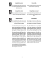 3
3
-
 4
4
-
 5
5
-
 6
6
-
 7
7
-
 8
8
-
 9
9
-
 10
10
-
 11
11
-
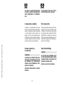 12
12
-
 13
13
-
 14
14
-
 15
15
-
 16
16
-
 17
17
-
 18
18
-
 19
19
-
 20
20
-
 21
21
-
 22
22
-
 23
23
-
 24
24
-
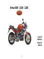 25
25
-
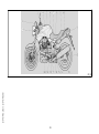 26
26
-
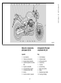 27
27
-
 28
28
-
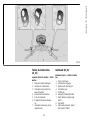 29
29
-
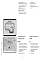 30
30
-
 31
31
-
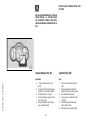 32
32
-
 33
33
-
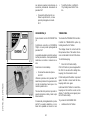 34
34
-
 35
35
-
 36
36
-
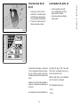 37
37
-
 38
38
-
 39
39
-
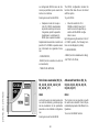 40
40
-
 41
41
-
 42
42
-
 43
43
-
 44
44
-
 45
45
-
 46
46
-
 47
47
-
 48
48
-
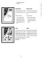 49
49
-
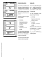 50
50
-
 51
51
-
 52
52
-
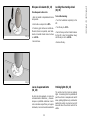 53
53
-
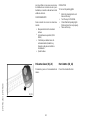 54
54
-
 55
55
-
 56
56
-
 57
57
-
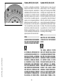 58
58
-
 59
59
-
 60
60
-
 61
61
-
 62
62
-
 63
63
-
 64
64
-
 65
65
-
 66
66
-
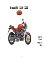 67
67
-
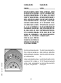 68
68
-
 69
69
-
 70
70
-
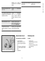 71
71
-
 72
72
-
 73
73
-
 74
74
-
 75
75
-
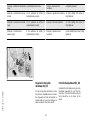 76
76
-
 77
77
-
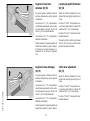 78
78
-
 79
79
-
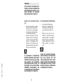 80
80
-
 81
81
-
 82
82
-
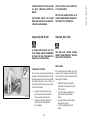 83
83
-
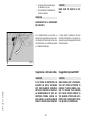 84
84
-
 85
85
-
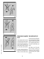 86
86
-
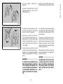 87
87
-
 88
88
-
 89
89
-
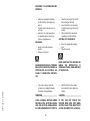 90
90
-
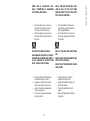 91
91
-
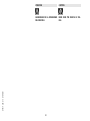 92
92
-
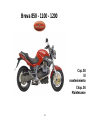 93
93
-
 94
94
-
 95
95
-
 96
96
-
 97
97
-
 98
98
-
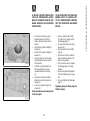 99
99
-
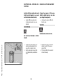 100
100
-
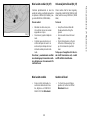 101
101
-
 102
102
-
 103
103
-
 104
104
-
 105
105
-
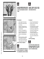 106
106
-
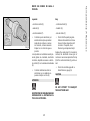 107
107
-
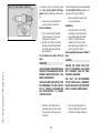 108
108
-
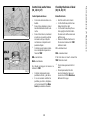 109
109
-
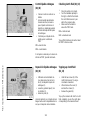 110
110
-
 111
111
-
 112
112
-
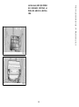 113
113
-
 114
114
-
 115
115
-
 116
116
-
 117
117
-
 118
118
-
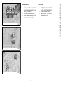 119
119
-
 120
120
-
 121
121
-
 122
122
-
 123
123
-
 124
124
-
 125
125
-
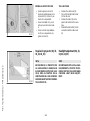 126
126
-
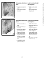 127
127
-
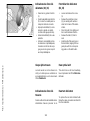 128
128
-
 129
129
-
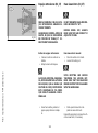 130
130
-
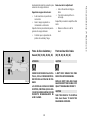 131
131
-
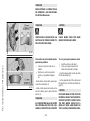 132
132
-
 133
133
-
 134
134
-
 135
135
-
 136
136
-
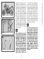 137
137
-
 138
138
-
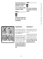 139
139
-
 140
140
-
 141
141
-
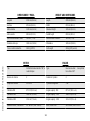 142
142
-
 143
143
-
 144
144
-
 145
145
-
 146
146
-
 147
147
-
 148
148
-
 149
149
-
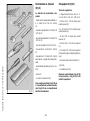 150
150
-
 151
151
-
 152
152
-
 153
153
-
 154
154
-
 155
155
-
 156
156
-
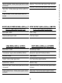 157
157
-
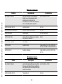 158
158
-
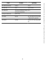 159
159
-
 160
160
-
 161
161
-
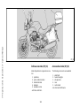 162
162
-
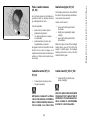 163
163
-
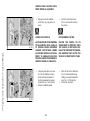 164
164
-
 165
165
-
 166
166
-
 167
167
-
 168
168
-
 169
169


MOTO GUZZI Breva 1100 Manual de usuario
- Categoría
- Motocicletas
- Tipo
- Manual de usuario
- Este manual también es adecuado para
en otros idiomas
- English: MOTO GUZZI Breva 1100 User manual
Artículos relacionados
-
MOTO GUZZI BELLAGIO Manual de usuario
-
-
-
-
-
-
MOTO GUZZI V7 CLASSIC El manual del propietario
-
-
-