Emerson SDN 5-24-480c El manual del propietario
- Tipo
- El manual del propietario

Installation Specications
Overcurrent Protection
Input: No internal fuses. UL Listed circuit breakers or fuses rated 3 A to 15 A,
480 V are required to be installed for input protection.
Output: Outputs are capable of providing high currents for short periods of
time for inductive load startup switching.
Relay
N.O. contact rated 200 mA/50 Vdc
Connections
An accessible disconnect device shall be installed external to the equipment.
Use copper conductors only, 60/75°C.
Input: Screw terminals. Connector size range: 16–10 AWG (1.5–6 mm2) for
solid or stranded conductors. Screw torque: 4.4-6.5 lb-inch (50-73 N-cm).
Output: Two terminals per output. Connector size range: 16–10 AWG (1.5–6
mm2) for solid or stranded conductors. Screw torque: 4.4-6.5 lb-inch (50-73
N-cm). Use only one copper wire per terminal for input and output.
Non-ratcheting torque driver recommended.
Note: During power supply replacement, ensure wiring connections are
properly terminated by verifying that terminal ID locations are the same. The
location and arrangement of the terminals can vary between manufacturer
and model number.
Safety
The power supply should meet the following conditions for safe use when
installed in a Class I, Zone 2, Groups IIC Hazardous Location:
(1) The equipment shall only be used in an area of not more than pollution
degree 2, as dened in IEC 60664-1.
(2) The equipment shall be installed in an enclosure that provides a degree
of protection not less than IP54 in accordance with IEC 60079-15.
(3) The operating temperature class (T-code) of this device was determined
to be T4.
Warning — Explosion Hazard — Do not disconnect the equipment
while the circuit is live or unless the area is known to be free of ignitable
concentrations.
Warning — Explosion Hazard — Do not open the unit. Do not substitute
components. Do not replace fuse.
Warning — Exposure to some chemicals may degrade the sealing
properties of materials used in the sealed relay device.
The power supplies should meet the following when installed in an ordinary
locations environment: Install in a controlled environment.
DIN Rail Mounting
Simple snap to DIN TS35/7.5 or TS35/15 rail system.
1. Tilt unit as illustrated.
2. Put unit onto the DIN rail.
3. Push unit downward until it stops.
4. Push at the lower front edge to lock.
5. Gently shake the unit to ensure that it is secure.
Especicaciones de Instalación
Protección de Sobreintensidad
Entrada: No contiene fusibles internos. Para protección de entrada se requiere
instalar interruptores de circuito o fusibles certicados por UL con valoración de 3
A a 15 A a 480 V.
Salida: Las tomas de salida son capaces de entregar corrientes elevadas durante
lapsos breves para el arranque de cargas inductivas.
Relé
Sin contacto clasicado 200 mA/50 V CC
Conexiones
Un dispositivo accesible de desconexión debe ser instalado externamente al
equipo.
Usar conductores de cobre únicamente, para 60/75°C.
Entrada: terminales tipo tornillo Rango de tamaños de conectores: 1,5–6 mm
2
para conductores unilares o trenzados. Torque de tornillo: 50-73 N-cm
Salida: dos terminales por salida. Rango de tamaños de conectores: 1,5–6 mm
2
para conductores unilares o trenzados. Torque de tornillo: 50-73 N-cm
Se recomienda un conductor de torque sin ajuste.
Nota: Durante la sustitución del suministro de energía, asegúrese de que las
conexiones de cableado estén correctamente nalizadas, vericando que las
ubicaciones de los ID de los terminales sean las mismas. La ubicación y la
disposición de los terminales pueden variar según el fabricante y el número de
modelo.
Seguridad
Las siguientes condiciones son requeridas para uso seguro de la fuente de
poder cuando la instalación es en áreas clasicadas como Clase I, Zona 2,
Grupo IIC de Ubicación Peligrosa:
(1) El equipo debe ser usado sólo en un área de no más de un grado 2 de
contaminación, tal como se dene en la norma IEC 60664-1.
(2) El equipo debe instalarse en el interior de un recinto que proporciona un
grado de protección no inferior a IP54 de acuerdo con la norma IEC 60079-15.
(3) El código de temperatura (T-code) de operación de este equipo es de clase
T4.
Advertencia — Peligro de Explosión — No desconecte el equipo si el circuito
está conectado, exceptuando si se sabe que no existen concentraciones
inamables en el área.
Advertencia — Peligro de Explosión — No abra la unidad. No substituya
componentes.
Advertencia — La exposición a ciertas sustancias químicas podría degradar las
propiedades selladoras de los materiales utilizados en el relé sellado del equipo.
Las fuentes de alimentación deben cumplir con lo siguiente cuando se instalen
en un entorno de áreas ordinarias: instalar en un entorno controlado.
Montaje en Riel DIN
Se adapta de manera sencilla en sistema Riel DIN TS35/7.5 ó Sistema TS35/15.
1. Incline la unidad como se ilustra.
2. Póngala sobre el Riel DIN.
3. Empuje hacia abajo hasta que se detenga.
4. Empuje de la parte baja del frente para asegurar.
5. Mueva la unidad ligeramente para vericar está segura.
Technical Specications
Input
Nominal Voltage 380–480 Vac, 3Ph
Inrush Current <25A
Power Factor (PFC) EN61000-3-2 Class A
Nominal Frequency 50/60 Hz
Output
Nominal Voltage 24 V (Adjustable from 24–28 Vdc)
Current 5 A
Power 120 W
Power Boost 1.5 x nominal current for 4 s
Hold-up Time
>20 ms (full load, 380 Vac input @ T
amb
+25°C)
to 95% output voltage
Tolerance <
± 2% overall
• Line Regulation <0.5%
• Load Regulation <0.5%
• Time and Temperature
Drift
<1%
Initial Voltage Setting 24.5 V ± 1%
Ripple <50 mVpp
Power Back Immunity < 35 V: no damage, auto-recovery
Parallel Operation Switch selectable
Overvoltage Protection >30.5 Vdc, but <33 Vdc auto recovery
Environmental Data
Ambient Temperature
Storage/Shipment: -40°C to +85°C.
Operating: -40°C to +60°C at full load. Derate
120 W by 6 W per °C to 60 W from +60°C to
+70°C
Degree of Protection IP20 (EN60529)
Minimum Required Free
Space for Cooling
0.98 in. (25 mm) above and below; 0.98 in. (25
mm) left and right; 0.98 in (25 mm) front. Do
not obstruct air ow.
Weight 1.15 lb. (520 g)
Certications
UL 508/CSA C22.2 No. 107.1
UL 60950-1/CSA C22.2 60950-1
UL 60079-0, UL 60079-15
Class I, Zone 2 AEx nA nC IIC T4 Gc
CAN/CSA 60079-0, CAN/CSA 60079-15
Class I, Zone 2 Ex nA nC IIC T4 U
IEC60950-1, EN60950-1
II 3 G Ex ec nC IIC T4 Gc, DEMKO 11ATEX1057365X
EN60079-0, EN60079-7, EN60079-15
IECEx Ex ec nC IIC T4 Gc, IECEx UL15.0018X
IEC60079, IEC60079-7, IEC60079-15
Ex nA nC IIC Gc U, №TC RU C-US.MШ06.B.00166
Type Approved
Emissions/Immunity
EN61000-6-1, EN61000-6-2, EN61000-6-3, EN61000-6-4, EN61326-1,
EN55011 Class B, EN55022, EN55024, EN61000-3-2, EN61000-3-3, SEMI
F47 Sag Immunity
Datos Técnicos
Entrada
Voltaje Nominal 380–480 V CA, 3Ph
Arranque <25A
Factor de Potencia (PFC) EN61000-3-2 Clase A
Frecuencia Nominal 50/60 Hz
Salida
Voltaje Nominal 24 V (Ajustable from 24–28 V CC)
Corriente 5 A
Potencia 120 W
Elevación de Potencia 1.5 x la corriente nominal por 4 s
Tiempo de Retención
>20 ms (la carga llena, 380 V CA entrada @ T
amb
+ 25°C) a 95% de voltaje de salida
Tolerancia <± 2% en conjunto
• Regulación de Línea <0.5%
• Regulación de Carga <0.5%
• Desviación de Tiempo
y Temp
<1%
Ajuste Inicial de Voltaje 24.5 V ± 1%
Rizo <50 mVpp
Inmunidad de Potencia
Inversa
< 35 V: no implica daño, autorecuperación
Operación Paralela Interruptor seleccionable
Protección de Sobre
Voltaje
>30.5 V CC, pero <33 V CC recuperación
automática
Datos Ambientales
Temperatura Ambiente
Almacenamiento/Embarque: -40°C to +85°C
Carga nominal completa: -40°C a +60°C en carga
llena. Disminución de 120 W a razón de 6 W por
°C hasta 60 W desde +60 °C hasta +70 °C
Grado de Protección IP20 (EN60529)
Espacio Requerido para
Enfriamiento
0.98 in. (25mm) por encima y por debajo; 0.98
in. (25mm) izquierda y derecha; 0.98 in (25 mm)
delante. No obstruya ujo aéreo.
Peso 520 g (1.15 lb.)
Certicaciones
UL 508/CSA C22.2 No. 107.1
UL 60950-1/CSA C22.2 60950-1
UL 60079-0, UL 60079-15
Class I, Zone 2 AEx nA nC IIC T4 Gc
CAN/CSA 60079-0, CAN/CSA 60079-15
Class I, Zone 2 Ex nA nC IIC T4 U
IEC60950-1, EN60950-1
II 3 G Ex ec nC IIC T4 Gc, DEMKO 11ATEX1057365X
EN60079-0, EN60079-7, EN60079-15
IECEx Ex ec nC IIC T4 Gc, IECEx UL15.0018X
IEC60079, IEC60079-7, IEC60079-15
Ex nA nC IIC Gc U, №TC RU C-US.MШ06.B.00166
Tipo Aprobado
Emisiones/Inmmunidad
EN61000-6-1, EN61000-6-2, EN61000-6-3, EN61000-6-4, EN61326-1, EN55011
Clase B, EN55022, EN55024, EN61000-3-2, EN61000-3-3, SEMIF47 Inmunidad
a Picos
Fuentes de alimentación
SDN 5-24-480C
Manual de instrucciones
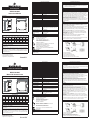
Dimensiones
5.51 in. [140.0 mm]
4.85 in. [123.3 mm]
4.73 in. [120.2 mm]
4.36 in. [110.8 mm]
4.79 in. [121.6 mm]
1.97 in. [50.0 mm]
Power Supply
Diagnósticos LED
LED OK
La
Perdida
de CA
CA Baja No CC
Alta
Carga
Sobre-
carga
Cali-
ente
Muy
Cali-
ente
Entrada Verde --- Ámbar Verde Verde Verde Verde Verde
Salida Verde --- Verde --- Ámbar Ámbar Verde ---
Alarma --- --- --- Rojo Ámbar Rojo Ámbar Ámbar
Soporte técnico
(800) 377-4384 • (847) 268-6651
www.solahd.com
Aunque se ha tomado toda precaución para asegurar precisión e integridad en
esta información, Appleton Grp LLC d/b/a Appleton Group no asume ninguna
responsabilidad y deniega toda responsabilidad por daños que resulten por el uso
de esta información o por cualquier error u omisión. Las especicaciones están
sujetas a cambios sin previo aviso.
P/N: A272-229 Rev. 8 02/2018
© 2018 Appleton Grp LLC d/b/a
Appleton Group. All rights reserved.
Power Supplies
SDN 5-24-480C
Instruction Manual
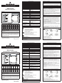
Dimensions
5.51 in. [140.0 mm]
4.85 in. [123.3 mm]
4.73 in. [120.2 mm]
4.36 in. [110.8 mm]
4.79 in. [121.6 mm]
1.97 in. [50.0 mm]
Power Supply
LED Diagnostics
LED OK
Loss
of AC
Low
AC
No
DC
High
Load
Over-
load
Hot
Too
Hot
Input Green --- Amber Green Green Green Green Green
Output Green --- Green --- Amber Amber Green ---
Alarm --- --- --- Red Amber Red Amber Amber
Technical Support
(800) 377-4384 • (847) 268-6651
www.solahd.com
While every precaution has been taken to ensure accuracy and completeness
in this manual, Appleton Grp LLC d/b/a Appleton Group assumes no
responsibility, and disclaims all liability for damages resulting from use of
this information or for any errors or omissions. Specications are subject to
change without notice.
P/N: A272-229 Rev. 8 02/2018
© 2018 Appleton Grp LLC d/b/a
Appleton Group. All rights reserved.
La página se está cargando...
Transcripción de documentos
Technical Specifications Input Nominal Voltage Inrush Current Power Factor (PFC) Nominal Frequency Output Nominal Voltage Current Power Power Boost Power Supplies SDN 5-24-480C Instruction Manual Hold-up Time Tolerance • Line Regulation • Load Regulation • Time and Temperature Drift Initial Voltage Setting Ripple Power Back Immunity Parallel Operation Overvoltage Protection Environmental Data Dimensions 4.73 in. [120.2 mm] 4.85 in. [123.3 mm] 5.51 in. [140.0 mm] 1.97 in. [50.0 mm] 4.36 in. [110.8 mm] Power Supply Ambient Temperature Degree of Protection 4.79 in. [121.6 mm] Minimum Required Free Space for Cooling Weight Certifications LED Diagnostics LED OK Loss of AC Input Green --- Amber Green Green Green Green Green Output Green --- Green --- Alarm --- --- Red --- Low AC No DC High Load Overload Hot Amber Amber Green Amber Red 380–480 Vac, 3Ph <25A EN61000-3-2 Class A 50/60 Hz 24 V (Adjustable from 24–28 Vdc) 5A 120 W 1.5 x nominal current for 4 s >20 ms (full load, 380 Vac input @ Tamb +25°C) to 95% output voltage < ± 2% overall <0.5% <0.5% <1% 24.5 V ± 1% <50 mVpp < 35 V: no damage, auto-recovery Switch selectable >30.5 Vdc, but <33 Vdc auto recovery Storage/Shipment: -40°C to +85°C. Operating: -40°C to +60°C at full load. Derate 120 W by 6 W per °C to 60 W from +60°C to +70°C IP20 (EN60529) 0.98 in. (25 mm) above and below; 0.98 in. (25 mm) left and right; 0.98 in (25 mm) front. Do not obstruct air flow. 1.15 lb. (520 g) UL 508/CSA C22.2 No. 107.1 Too Hot UL 60950-1/CSA C22.2 60950-1 UL 60079-0, UL 60079-15 Class I, Zone 2 AEx nA nC IIC T4 Gc CAN/CSA 60079-0, CAN/CSA 60079-15 Class I, Zone 2 Ex nA nC IIC T4 U --- Amber Amber IEC60950-1, EN60950-1 Technical Support IECEx While every precaution has been taken to ensure accuracy and completeness in this manual, Appleton Grp LLC d/b/a Appleton Group assumes no responsibility, and disclaims all liability for damages resulting from use of this information or for any errors or omissions. Specifications are subject to change without notice. Ex nA nC IIC Gc U, №TC RU C-US.MШ06.B.00166 Type Approved Emissions/Immunity EN61000-6-1, EN61000-6-2, EN61000-6-3, EN61000-6-4, EN61326-1, EN55011 Class B, EN55022, EN55024, EN61000-3-2, EN61000-3-3, SEMI F47 Sag Immunity Entrada Voltaje Nominal Arranque Factor de Potencia (PFC) Frecuencia Nominal Salida Voltaje Nominal Corriente Potencia Elevación de Potencia Tiempo de Retención Tolerancia • Regulación de Línea • Regulación de Carga • Desviación de Tiempo y Temp Ajuste Inicial de Voltaje Rizo Inmunidad de Potencia Inversa Operación Paralela Protección de Sobre Voltaje Datos Ambientales 4.73 in. [120.2 mm] 1.97 in. [50.0 mm] 4.85 in. [123.3 mm] 1. Tilt unit as illustrated. 2. Put unit onto the DIN rail. 5. Gently shake the unit to ensure that it is secure. Dimensiones 5.51 in. [140.0 mm] DIN Rail Mounting Simple snap to DIN TS35/7.5 or TS35/15 rail system. 4. Push at the lower front edge to lock. SDN 5-24-480C Manual de instrucciones 4.36 in. [110.8 mm] Power Supply Temperatura Ambiente Grado de Protección Espacio Requerido para Enfriamiento 4.79 in. [121.6 mm] Peso Certificaciones Diagnósticos LED La Perdida CA Baja No CC de CA --- Ámbar Verde Salida Verde --- Verde --- Alarma --- --- --- Rojo Alta Carga Sobrecarga Caliente Muy Caliente Verde Verde Verde Verde Ámbar Ámbar Verde --- Ámbar Ámbar Ámbar Rojo Soporte técnico (800) 377-4384 • (847) 268-6651 [email protected] www.solahd.com Aunque se ha tomado toda precaución para asegurar precisión e integridad en esta información, Appleton Grp LLC d/b/a Appleton Group no asume ninguna responsabilidad y deniega toda responsabilidad por daños que resulten por el uso de esta información o por cualquier error u omisión. Las especificaciones están sujetas a cambios sin previo aviso. P/N: A272-229 Rev. 8 02/2018 © 2018 Appleton Grp LLC d/b/a Appleton Group. All rights reserved. The power supplies should meet the following when installed in an ordinary locations environment: Install in a controlled environment. 3. Push unit downward until it stops. Fuentes de alimentación Entrada Verde The power supply should meet the following conditions for safe use when installed in a Class I, Zone 2, Groups IIC Hazardous Location: (1) The equipment shall only be used in an area of not more than pollution degree 2, as defined in IEC 60664-1. (2) The equipment shall be installed in an enclosure that provides a degree of protection not less than IP54 in accordance with IEC 60079-15. (3) The operating temperature class (T-code) of this device was determined to be T4. Warning — Explosion Hazard — Do not disconnect the equipment while the circuit is live or unless the area is known to be free of ignitable concentrations. Warning — Explosion Hazard — Do not open the unit. Do not substitute components. Do not replace fuse. Warning — Exposure to some chemicals may degrade the sealing properties of materials used in the sealed relay device. Ex ec nC IIC T4 Gc, IECEx UL15.0018X IEC60079, IEC60079-7, IEC60079-15 P/N: A272-229 Rev. 8 02/2018 © 2018 Appleton Grp LLC d/b/a Appleton Group. All rights reserved. OK Safety II 3 G Ex ec nC IIC T4 Gc, DEMKO 11ATEX1057365X EN60079-0, EN60079-7, EN60079-15 (800) 377-4384 • (847) 268-6651 [email protected] www.solahd.com LED Installation Specifications Overcurrent Protection Input: No internal fuses. UL Listed circuit breakers or fuses rated 3 A to 15 A, 480 V are required to be installed for input protection. Output: Outputs are capable of providing high currents for short periods of time for inductive load startup switching. Relay N.O. contact rated 200 mA/50 Vdc Connections An accessible disconnect device shall be installed external to the equipment. Use copper conductors only, 60/75°C. Input: Screw terminals. Connector size range: 16–10 AWG (1.5–6 mm2) for solid or stranded conductors. Screw torque: 4.4-6.5 lb-inch (50-73 N-cm). Output: Two terminals per output. Connector size range: 16–10 AWG (1.5–6 mm2) for solid or stranded conductors. Screw torque: 4.4-6.5 lb-inch (50-73 N-cm). Use only one copper wire per terminal for input and output. Non-ratcheting torque driver recommended. Note: During power supply replacement, ensure wiring connections are properly terminated by verifying that terminal ID locations are the same. The location and arrangement of the terminals can vary between manufacturer and model number. Datos Técnicos 380–480 V CA, 3Ph <25A EN61000-3-2 Clase A 50/60 Hz 24 V (Ajustable from 24–28 V CC) 5A 120 W 1.5 x la corriente nominal por 4 s >20 ms (la carga llena, 380 V CA entrada @ Tamb + 25°C) a 95% de voltaje de salida <± 2% en conjunto <0.5% <0.5% <1% 24.5 V ± 1% <50 mVpp < 35 V: no implica daño, autorecuperación Interruptor seleccionable >30.5 V CC, pero <33 V CC recuperación automática Almacenamiento/Embarque: -40°C to +85°C Carga nominal completa: -40°C a +60°C en carga llena. Disminución de 120 W a razón de 6 W por °C hasta 60 W desde +60 °C hasta +70 °C IP20 (EN60529) 0.98 in. (25mm) por encima y por debajo; 0.98 in. (25mm) izquierda y derecha; 0.98 in (25 mm) delante. No obstruya flujo aéreo. 520 g (1.15 lb.) UL 508/CSA C22.2 No. 107.1 UL 60950-1/CSA C22.2 60950-1 UL 60079-0, UL 60079-15 Class I, Zone 2 AEx nA nC IIC T4 Gc CAN/CSA 60079-0, CAN/CSA 60079-15 Class I, Zone 2 Ex nA nC IIC T4 U IEC60950-1, EN60950-1 Especificaciones de Instalación Protección de Sobreintensidad Entrada: No contiene fusibles internos. Para protección de entrada se requiere instalar interruptores de circuito o fusibles certificados por UL con valoración de 3 A a 15 A a 480 V. Salida: Las tomas de salida son capaces de entregar corrientes elevadas durante lapsos breves para el arranque de cargas inductivas. Relé Sin contacto clasificado 200 mA/50 V CC Conexiones Un dispositivo accesible de desconexión debe ser instalado externamente al equipo. Usar conductores de cobre únicamente, para 60/75°C. Entrada: terminales tipo tornillo Rango de tamaños de conectores: 1,5–6 mm2 para conductores unifilares o trenzados. Torque de tornillo: 50-73 N-cm Salida: dos terminales por salida. Rango de tamaños de conectores: 1,5–6 mm2 para conductores unifilares o trenzados. Torque de tornillo: 50-73 N-cm Se recomienda un conductor de torque sin ajuste. Nota: Durante la sustitución del suministro de energía, asegúrese de que las conexiones de cableado estén correctamente finalizadas, verificando que las ubicaciones de los ID de los terminales sean las mismas. La ubicación y la disposición de los terminales pueden variar según el fabricante y el número de modelo. Seguridad Las siguientes condiciones son requeridas para uso seguro de la fuente de poder cuando la instalación es en áreas clasificadas como Clase I, Zona 2, Grupo IIC de Ubicación Peligrosa: (1) El equipo debe ser usado sólo en un área de no más de un grado 2 de contaminación, tal como se define en la norma IEC 60664-1. (2) El equipo debe instalarse en el interior de un recinto que proporciona un grado de protección no inferior a IP54 de acuerdo con la norma IEC 60079-15. (3) El código de temperatura (T-code) de operación de este equipo es de clase T4. Advertencia — Peligro de Explosión — No desconecte el equipo si el circuito está conectado, exceptuando si se sabe que no existen concentraciones inflamables en el área. Advertencia — Peligro de Explosión — No abra la unidad. No substituya componentes. Advertencia — La exposición a ciertas sustancias químicas podría degradar las propiedades selladoras de los materiales utilizados en el relé sellado del equipo. Las fuentes de alimentación deben cumplir con lo siguiente cuando se instalen en un entorno de áreas ordinarias: instalar en un entorno controlado. Montaje en Riel DIN Se adapta de manera sencilla en sistema Riel DIN TS35/7.5 ó Sistema TS35/15. II 3 G Ex ec nC IIC T4 Gc, DEMKO 11ATEX1057365X EN60079-0, EN60079-7, EN60079-15 IECEx Ex ec nC IIC T4 Gc, IECEx UL15.0018X IEC60079, IEC60079-7, IEC60079-15 Ex nA nC IIC Gc U, №TC RU C-US.MШ06.B.00166 Tipo Aprobado Emisiones/Inmmunidad EN61000-6-1, EN61000-6-2, EN61000-6-3, EN61000-6-4, EN61326-1, EN55011 Clase B, EN55022, EN55024, EN61000-3-2, EN61000-3-3, SEMIF47 Inmunidad a Picos 1. 2. 3. 4. 5. Incline la unidad como se ilustra. Póngala sobre el Riel DIN. Empuje hacia abajo hasta que se detenga. Empuje de la parte baja del frente para asegurar. Mueva la unidad ligeramente para verificar está segura.-
 1
1
-
 2
2


Emerson SDN 5-24-480c El manual del propietario
- Tipo
- El manual del propietario
en otros idiomas
Artículos relacionados
-
Emerson SDN 10-24-480C El manual del propietario
-
-
-
-
-
Otros documentos
-
SolaHD SDN 40-24-480 El manual del propietario
-
-
-
-
-
-
-
-
-