Klein Tools VDV526-100 Instrucciones de operación
- Categoría
- Probadores de redes de cable
- Tipo
- Instrucciones de operación

VDV526-100
INSTRUCTIONS / INSTRUCCIONES / DIRECTIVES
ENGLISH
ENGLISH ENGLISH
ESPAÑOL
ESPAÑOL
GENERAL SPECIFICATIONS
The Klein Tools LAN Explorer™ is a portable voice and data cable tester. It tests and
troubleshoots RJ45, RJ11 and RJ12 terminated cables and patch cords.
• Operating Altitude: 6562 ft. (2000 m)
• Relative Humidity: <90% non-condensing
• Operating Temperature: 14°F to 122°F (-10°C to 50°C)
• Storage Temperature: -4°F to 122°F (-20°C to 50°C)
• Dimensions: 4.9" x 2.5" x 1.3" (12.6 x 6.4 x 3.2 cm)
• Weight: 5.0 oz. (142 g) including batteries and remote
• Battery: 9V
• Maximum non-damaging voltage between pins (RJ Jacks): 66V DC or 55V AC
• Cable Types: Shielded or Unshielded; CAT-7, CAT-6/6A, CAT-5e, CAT-3
• Maximum Cable Length: 1000 ft. (305 m)
• Minimum Cable Length (for Split Pair detection): 1.5 ft. (0.5 m)
Specifications subject to change.
WARNINGS
To ensure safe operations, follow these instructions. Failure to observe these warnings
can result in re, electric shock, severe injury or death.
• Read all safety Information before using the product.
• Carefully read all instructions.
• The LAN Explorer is designed for use on unpowered/dark cable systems.
• Do Not connect LAN Explorer to live AC power.
• Poorly terminated plugs will damage the jacks on the LAN Explorer. Visually inspect plug
before inserting it into the tester.
• This product is for indoor use only.
• Turn off LAN Explorer before attempting to replace batteries.
• Do not open the case, other than the battery compartment.
• The battery door must be in place and secure before operating product.
CAUTION
• No user-serviceable parts inside.
• Do NOT expose to open flame, heat sources, equipment that produces heat, or extremes
of environmental temperature.
KEEP THESE INSTRUCTIONS FOR FUTURE REFERENCE
SYMBOLS ON TESTER
Warning or
Caution
Wear approved
eye protection
NOT insulated - Will
NOT protect against
electric shock
Read all
instructions
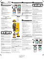
FEATURE DETAILS
5
9
10
3
1
11
8
7
4
2
12
6
TESTER
1.
RJ45 Shielded Jack
2.
RJ11/RJ12 Shielded Jack
3.
PASS Indicators
4.
Shield Indicator
5.
Test Button
6.
Low Battery Indicator
7.
Power On Indicator
8.
FAULT Indicators
9.
Battery Cover
REMOTE
10.
Release Latch
11.
RJ45 Shielded Jack
12.
RJ11/RJ12 Shielded Jack
WIRING CONDITION INDICATORS
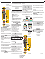
NOTE: See FIG. 1 below for examples of correctly and incorrectly wired connectors.
PASS INDICATORS
3
Will illuminate if the cable is properly wired. For RJ45, the 4 pairs are wired according to
the T568A/568B data cable standards or if cable is wired straight through (i.e., Pin 1 on
near end is wired to Pin 1 on far end; Pin 2 on near end is wired to Pin 2 on far end, etc.).
FAULT INDICATORS
8
MISWIRE: Illuminates if the cable is not wired to one of the cabling standards shown
below, or if the conductor wire order on the near end do not match the conductor wire
order on the opposite end, i.e. if Pin 1 on near end is wired to Pin 2 on the far end.
OPEN:
Illuminates if one or more of the conductor wires on the near end are not terminated
properly on the far end, or if any of the near-end contact pins are not properly terminated.
SHORT : Illuminates when two or more conductor wires make contact with each other.
SHIELDED INDICATOR
4
Illuminates when a shielded (ground wire or foil) data cable is properly connected at both ends,
either by ground wire or by foil.
NOTE:
•
When “OPEN” and “MISWIRE” exist simultaneously, only can be judged as “OPEN”.
•
When “SHORT” and “MISWIRE” exist simultaneously, only can be judged as“SHORT”
•
When “OPEN” and “SHORT” exist simultaneously for one wire, only can display one status.
If “OPEN” first then “SHORT”, judge as “OPEN”; If “SHORT” first then “OPEN”, judge as
“SHORT”.
•
I
f only one fault (“OPEN” or “SHORT”) happens to one wire. For example, wire#1 is open,
wire#4 and wire#5 are shorted, then both “OPEN” and “SHORT” can be detected and
displayed.
NOTE: A Cross-Over Wired cable will flash the MISWIRE and PASS LEDs simultaneously.
On an RJ12-terminated wire with pin 1 and 6 open faults, "RJ11 PASS" will be the response.
WIRING CONDITION INDICATORS
FIG. 1
NEAR END
FAR END
PROPERLY WIRED T568A
The 1-2 pair pins are shorted together and the
7-8 pair is open. The SHORT LED and OPEN
LED will illuminate simultaneously.
Pins 1 and 2 on the Near end are
connected to Pins 2 and 1 on the Far End.
PIN 1
PIN 8
T568A CABLE WITH
SHORT AND OPEN
NEAR END
FAR END
NEAR END
FAR END
T568A CABLE WITH A MISWIRE
AND UNRECOGNIZED CONTINUITY
PROPERLY WIRED T568B
NEAR END
FAR END
OPERATING INSTRUCTIONS
POWERING ON AND OFF / TESTING A CABLE
The LAN Explorer™ has a single button to start a test. When powered off, a short press of
the test button
5
causes the LAN Explorer™ to turn on, and a cable test to be executed.
See INDICATORS section. The results are displayed for 30 seconds before powering off.
If another short press occurs before the 30 second time-out, another test cycle will begin,
followed by another 30 second time-out.
The LAN Explorer™ will automatically power off if there is no test result change for 30 seconds.
To manually power off theLAN Explorer™, press the test button
5
for 2 seconds.
MAINTENANCE
BATTERY REPLACEMENT
When the Low Battery indicator
6
blinks or tester does not turn on, the battery must be
replaced.
1. Loosen screw in battery cover
9
to access the battery compartment.
2. Remove and recycle exhausted battery.
3. Install new 9V alkaline or carbon zinc battery. Note proper polarity.
4. Replace battery door and fasten securely with screw. Do not over-tighten.
CLEANING
Turn tester off and disconnect any cables. Wipe with a clean, dry lint-free cloth.
Do not use abrasive cleaners or solvents.
STORAGE
Remove the battery when the unit is not in use for a prolonged period of time. Do not
expose to high temperatures or humidity. After a period of storage in extreme conditions
exceeding the limits mentioned in the General Specifications section, allow the unit to
return to normal operating conditions before using.
WARRANTY
www.kleintools.com/warranty
DISPOSAL / RECYCLE
Do not place equipment and its accessories in the trash. Items must be properly
disposed of in accordance with local regulations. Please see www.epa.gov or
www.erecycle.org for additional information.
CUSTOMER SERVICE
KLEIN TOOLS, INC.
450 Bond Street Lincolnshire, IL 60069
1-877-775-5346
www.kleintools.com
ESPECIFICACIONES GENERALES
El LAN Explorer™ de Klein Tools es un probador portátil de cables de voz y datos. Prueba y
soluciona problemas de cables terminados con conector RJ45, RJ11 y RJ12 y empalmes
de cables conductores.
• Altitud de funcionamiento: 6562' (2000m)
• Humedad relativa: <90%, sin condensación
• Temperatura de operación: de 14°F a 122°F (de -10°C a 50°C)
• Temperatura de almacenamiento: de -4°F a 122°F (de -20°C a 50°C)
• Dimensiones: 4,9" × 2,5" × 1,3" (12,6 × 6,4 × 3,2cm)
• Peso: 5,0oz (142g) incluida la batería y el transmisor remoto
• Batería: 9V
• Voltaje máximo que no produce daños entre clavijas
(conectores RJ): 66VCD o 55VCA
• Tipos de cables: Blindado o no blindado; CAT-7, CAT-6/6A, CAT-5e, CAT-3
• Longitud máxima del cable: 1000' (305m)
• Longitud mínima del cable (para detección de pares divididos): 1,5' (0,5m)
Especificaciones sujetas a cambios.
ADVERTENCIAS
Para garantizar un funcionamiento seguro, siga estas instrucciones. El incumplimiento
de estas advertencias puede provocar un incendio, choque eléctrico, lesiones graves o
la muerte.
• Lea toda la información de seguridad antes de usar el producto.
• Lea atentamente todas las instrucciones.
• El LAN Explorer está diseñado para ser utilizado en sistemas de cables inactivos/inutilizados.
• No conecte el LAN Explorer a una fuente de alimentación de CA activa.
• Los conectores con terminaciones defectuosas dañarán los conectores del LAN Explorer.
Inspeccione visualmente el conector antes de insertarlo en el probador.
• Este producto está diseñado solo para uso en interiores.
• Apague el LAN Explorer antes de intentar reemplazar la batería.
• No abra la carcasa, excepto el compartimento de la batería.
• La tapa del compartimento de la batería debe estar ajustada en su lugar antes de operar
el producto.
PRECAUCIÓN
• El dispositivo no contiene en su interior piezas que el usuario pueda reparar.
• NO lo exponga a llamas abiertas, fuentes de calor, equipos que generen calor o
temperaturas ambiente extremas.
CONSERVE ESTAS INSTRUCCIONES PARA CONSULTARLAS EN EL FUTURO
SÍMBOLOS DEL PROBADOR
Advertencia
oprecaución
Use protección
para ojos
aprobada
SIN aislamiento -
NO brinda protección
contrachoque eléctrico
Lea todas las
instrucciones
INDICADORES DE CONDICIONES DE CABLEADO
NOTA: Consulte la FIG. 1 abajo para ver ejemplos de conectores con cableados correctos
e incorrectos.
INDICADORES “PASS” (PRUEBA APROBADA)
3
Se encenderán si el cable está cableado correctamente. Para el conector RJ45, los 4
pares están cableados de acuerdo con los estándares de cables de datos T568A/568B
o si el cable está cableado de forma recta (es decir, si la clavija 1 en el extremo cercano
está conectada a la clavija 1 en el extremo lejano; la clavija 2 en el extremo cercano está
conectada a la clavija 2 en el extremo lejano, etc.).
INDICADORES “FAULT” (FALLA)
8
“MISWIRE” (ERROR DE CABLEADO): Se enciende si el cableado no está hecho de
acuerdo con los estándares de cableado que se muestran abajo, o si el orden de cables
conductores en el extremo cercano no coincide con la disposición de las clavijas del
cable conductor en el extremo contrario, es decir, si la Clavija1 en el extremo cercano
está conectada a la Clavija2 en el extremo lejano.
“OPEN” (CIRCUITO ABIERTO):
Se enciende si uno o más de los cables conductores en el
extremo cercano no están terminados adecuadamente en el extremo lejano, o si alguna de
las clavijas de contacto del extremo cercano no tienen la terminación correcta.
“SHORT” (CORTOCIRCUITO): Se enciende cuando dos o más alambres conductores
hacen contacto entre sí.
INDICADOR “SHIELDED” (CON BLINDAJE)
4
Se enciende cuando se conecta adecuadamente un cable de datos blindado
(puesta a tierra o cinta de aluminio) en ambos extremos.
NOTA:
•
Cuando “OPEN” (Circuito abierto) y “MISWIRE” (Error de cableado) se presentan
simultáneamente, solo se puede determinar como Circuito abierto.
•
Cuando “SHORT” (Cortocircuito) y “MISWIRE” (Error de cableado) se presentan
simultáneamente, solo se puede determinar como Cortocircuito.
•
Cuando “OPEN” (Circuito abierto) y “SHORT” (Cortocircuito) se presentan
simultáneamente en un cable, solo se puede mostrar un estado. Si pasa de “OPEN”
(Circuito abierto) a “SHORT” (Cortocircuito), se determina como “OPEN” (Circuito
abierto); si pasa de “SHORT” (Cortocircuito) a “OPEN” (Circuito abierto), se determina
como “SHORT” (Cortocircuito).
•
Si
solo se presenta una falla [“OPEN” (Circuito abierto) o “SHORT” (Cortocircuito)] en un
cable. Por ejemplo, el cable n.º1 está en circuito abierto, los cables n.º4 y n.º5 están en
cortocircuito, así ambos estados “OPEN” (Circuito abierto) y “SHORT” (Cerrado) se pueden
detectar y visualizar.
NOTA: Al conectar un cable cruzado, se encenderán de manera simultánea los LED
“MISWIRE” (Error de cableado) y “PASS” (Prueba aprobada). En un cable terminado
con un conector RJ12 con fallas de circuito abierto en las clavijas 1 y 6, la respuesta será
“PASS” (Prueba aprobada) RJ11.
INDICADORES DE CONDICIONES DE CABLEADO
FIG. 1
EXTREMO
CERCANO
EXTREMO
CERCANO
EXTREMO
LEJANO
EXTREMO
LEJANO
T568A CORRECTAMENTE
CABLEADO
Las clavijas del par 1-2 están en cortocircuito
y el par 7-8 está abierto. El LED “SHORT”
(CORTOCIRCUITO) y el LED “OPEN”
(CIRCUITO ABIERTO) se encenderán
simultáneamente.
Las clavijas 1 y 2 en el extremo cercano
están conectadas a las clavijas 2 y 1 en el
extremo lejano.
CLAVIJA1
CLAVIJA8
CABLE T568A EN CORTOCIRCUITO
Y CIRCUITO ABIERTO
EXTREMO
CERCANO
EXTREMO
LEJANO
EXTREMO
CERCANO
EXTREMO
LEJANO
CABLE T568A CON ERROR DE
CABLEADO Y CONTINUIDAD
DESCONOCIDA
T568B CORRECTAMENTE
CABLEADO
Dwg Name: VDV526-100-1390289ART
Dwg No: 1390289 Rev: B
Pkg Dwg Ref: A3 ECO No: 031430
Color Reference: N/A
La página se está cargando...
Transcripción de documentos
ENGLISH FEATURE DETAILS KEEP THESE INSTRUCTIONS FOR FUTURE REFERENCE WARNINGS To ensure safe operations, follow these instructions. Failure to observe these warnings can result in fire, electric shock, severe injury or death. • Read all safety Information before using the product. • Carefully read all instructions. • The LAN Explorer is designed for use on unpowered/dark cable systems. • Do Not connect LAN Explorer to live AC power. • Poorly terminated plugs will damage the jacks on the LAN Explorer. Visually inspect plug before inserting it into the tester. • This product is for indoor use only. • Turn off LAN Explorer before attempting to replace batteries. • Do not open the case, other than the battery compartment. • The battery door must be in place and secure before operating product. CAUTION • No user-serviceable parts inside. • Do NOT expose to open flame, heat sources, equipment that produces heat, or extremes of environmental temperature. 1 2 1. 2. 3. 4. 5. 6. 7. 8. 9. TESTER RJ45 Shielded Jack RJ11/RJ12 Shielded Jack PASS Indicators Shield Indicator Test Button Low Battery Indicator Power On Indicator FAULT Indicators Battery Cover 3 4 5 7 6 8 9 SYMBOLS ON TESTER Warning or Caution Wear approved eye protection NOT insulated - Will NOT protect against electric shock Read all instructions 10 WIRING CONDITION INDICATORS NOTE: See FIG. 1 below for examples of correctly and incorrectly wired connectors. PASS INDICATORS 3 Will illuminate if the cable is properly wired. For RJ45, the 4 pairs are wired according to the T568A/568B data cable standards or if cable is wired straight through (i.e., Pin 1 on near end is wired to Pin 1 on far end; Pin 2 on near end is wired to Pin 2 on far end, etc.). FAULT INDICATORS 8 MISWIRE: Illuminates if the cable is not wired to one of the cabling standards shown below, or if the conductor wire order on the near end do not match the conductor wire order on the opposite end, i.e. if Pin 1 on near end is wired to Pin 2 on the far end. OPEN: Illuminates if one or more of the conductor wires on the near end are not terminated properly on the far end, or if any of the near-end contact pins are not properly terminated. SHORT : Illuminates when two or more conductor wires make contact with each other. REMOTE 11 12 10. Release Latch 11. RJ45 Shielded Jack 12. RJ11/RJ12 Shielded Jack OPERATING INSTRUCTIONS POWERING ON AND OFF / TESTING A CABLE The LAN Explorer™ has a single button to start a test. When powered off, a short press of the test button 5 causes the LAN Explorer™ to turn on, and a cable test to be executed. See INDICATORS section. The results are displayed for 30 seconds before powering off. If another short press occurs before the 30 second time-out, another test cycle will begin, followed by another 30 second time-out. SHIELDED INDICATOR 4 Illuminates when a shielded (ground wire or foil) data cable is properly connected at both ends, The LAN Explorer™ will automatically power off if there is no test result change for 30 seconds. either by ground wire or by foil. To manually power off theLAN Explorer™, press the test button 5 for 2 seconds. NOTE: MAINTENANCE • When “OPEN” and “MISWIRE” exist simultaneously, only can be judged as “OPEN”. BATTERY REPLACEMENT • When “SHORT” and “MISWIRE” exist simultaneously, only can be judged as“SHORT” • When “OPEN” and “SHORT” exist simultaneously for one wire, only can display one status. If “OPEN” first then “SHORT”, judge as “OPEN”; If “SHORT” first then “OPEN”, judge as “SHORT”. • If only one fault (“OPEN” or “SHORT”) happens to one wire. For example, wire#1 is open, wire#4 and wire#5 are shorted, then both “OPEN” and “SHORT” can be detected and displayed. NOTE: A Cross-Over Wired cable will flash the MISWIRE and PASS LEDs simultaneously. On an RJ12-terminated wire with pin 1 and 6 open faults, "RJ11 PASS" will be the response. When the Low Battery indicator 6 blinks or tester does not turn on, the battery must be replaced. 1. Loosen screw in battery cover 9 to access the battery compartment. 2. Remove and recycle exhausted battery. 3. Install new 9V alkaline or carbon zinc battery. Note proper polarity. 4. Replace battery door and fasten securely with screw. Do not over-tighten. STORAGE INDICADORES DE CONDICIONES DE CABLEADO Remove the battery when the unit is not in use for a prolonged period of time. Do not expose to high temperatures or humidity. After a period of storage in extreme conditions exceeding the limits mentioned in the General Specifications section, allow the unit to return to normal operating conditions before using. NOTA: Consulte la FIG. 1 abajo para ver ejemplos de conectores con cableados correctos e incorrectos. INDICADORES “PASS” (PRUEBA APROBADA) 3 Se encenderán si el cable está cableado correctamente. Para el conector RJ45, los 4 WARRANTY pares están cableados de acuerdo con los estándares de cables de datos T568A/568B www.kleintools.com/warranty o si el cable está cableado de forma recta (es decir, si la clavija 1 en el extremo cercano está conectada a la clavija 1 en el extremo lejano; la clavija 2 en el extremo cercano está DISPOSAL / RECYCLE conectada a la clavija 2 en el extremo lejano, etc.). Do not place equipment and its accessories in the trash. Items must be properly INDICADORES “FAULT” (FALLA) 8 disposed of in accordance with local regulations. Please see www.epa.gov or www.erecycle.org for additional information. “MISWIRE” (ERROR DE CABLEADO): Se enciende si el cableado no está hecho de acuerdo con los estándares de cableado que se muestran abajo, o si el orden de cables CUSTOMER SERVICE conductores en el extremo cercano no coincide con la disposición de las clavijas del KLEIN TOOLS, INC. cable conductor en el extremo contrario, es decir, si la Clavija 1 en el extremo cercano 450 Bond Street Lincolnshire, IL 60069 está conectada a la Clavija 2 en el extremo lejano. 1-877-775-5346 “OPEN” (CIRCUITO ABIERTO): Se enciende si uno o más de los cables conductores en el [email protected] www.kleintools.com extremo cercano no están terminados adecuadamente en el extremo lejano, o si alguna de las clavijas de contacto del extremo cercano no tienen la terminación correcta. ESPAÑOL “SHORT” (CORTOCIRCUITO): Se enciende cuando dos o más alambres conductores ESPECIFICACIONES GENERALES hacen contacto entre sí. El LAN Explorer™ de Klein Tools es un probador portátil de cables de voz y datos. Prueba y INDICADOR “SHIELDED” (CON BLINDAJE) 4 soluciona problemas de cables terminados con conector RJ45, RJ11 y RJ12 y empalmes Se enciende cuando se conecta adecuadamente un cable de datos blindado de cables conductores. (puesta a tierra o cinta de aluminio) en ambos extremos. • Altitud de funcionamiento: 6562' (2000 m) NOTA: • Humedad relativa: <90 %, sin condensación • Cuando “OPEN” (Circuito abierto) y “MISWIRE” (Error de cableado) se presentan simultáneamente, solo se puede determinar como Circuito abierto. • Temperatura de operación: de 14 °F a 122 °F (de -10 °C a 50 °C) • Cuando “SHORT” (Cortocircuito) y “MISWIRE” (Error de cableado) se presentan • Temperatura de almacenamiento: de -4 °F a 122 °F (de -20 °C a 50 °C) simultáneamente, solo se puede determinar como Cortocircuito. • Dimensiones: 4,9" × 2,5" × 1,3" (12,6 × 6,4 × 3,2 cm) • Cuando “OPEN” (Circuito abierto) y “SHORT” (Cortocircuito) se presentan • Peso: 5,0 oz (142 g) incluida la batería y el transmisor remoto simultáneamente en un cable, solo se puede mostrar un estado. Si pasa de “OPEN” • Batería: 9 V (Circuito abierto) a “SHORT” (Cortocircuito), se determina como “OPEN” (Circuito • Voltaje máximo que no produce daños entre clavijas abierto); si pasa de “SHORT” (Cortocircuito) a “OPEN” (Circuito abierto), se determina (conectores RJ): 66 V CD o 55 V CA como “SHORT” (Cortocircuito). • Tipos de cables: Blindado o no blindado; CAT-7, CAT-6/6A, CAT-5e, CAT-3 • Si solo se presenta una falla [“OPEN” (Circuito abierto) o “SHORT” (Cortocircuito)] en un • Longitud máxima del cable: 1000' (305 m) cable. Por ejemplo, el cable n.º 1 está en circuito abierto, los cables n.º 4 y n.º 5 están en • Longitud mínima del cable (para detección de pares divididos): 1,5' (0,5 m) cortocircuito, así ambos estados “OPEN” (Circuito abierto) y “SHORT” (Cerrado) se pueden Especificaciones sujetas a cambios. detectar y visualizar. NOTA: Al conectar un cable cruzado, se encenderán de manera simultánea los LED CONSERVE ESTAS INSTRUCCIONES PARA CONSULTARLAS EN EL FUTURO “MISWIRE” (Error de cableado) y “PASS” (Prueba aprobada). En un cable terminado ADVERTENCIAS con un conector RJ12 con fallas de circuito abierto en las clavijas 1 y 6, la respuesta será Para garantizar un funcionamiento seguro, siga estas instrucciones. El incumplimiento “PASS” (Prueba aprobada) RJ11. de estas advertencias puede provocar un incendio, choque eléctrico, lesiones graves o la muerte. INDICADORES DE CONDICIONES DE CABLEADO • Lea toda la información de seguridad antes de usar el producto. T568A CORRECTAMENTE T568B CORRECTAMENTE FIG. 1 • Lea atentamente todas las instrucciones. CABLEADO CABLEADO • El LAN Explorer está diseñado para ser utilizado en sistemas de cables inactivos/inutilizados. • No conecte el LAN Explorer a una fuente de alimentación de CA activa. • Los conectores con terminaciones defectuosas dañarán los conectores del LAN Explorer. CLAVIJA 1 CLAVIJA 8 Inspeccione visualmente el conector antes de insertarlo en el probador. • Este producto está diseñado solo para uso en interiores. • Apague el LAN Explorer antes de intentar reemplazar la batería. CABLE T568A EN CORTOCIRCUITO CABLE T568A CON ERROR DE • No abra la carcasa, excepto el compartimento de la batería. CABLEADO Y CONTINUIDAD Y CIRCUITO ABIERTO • La tapa del compartimento de la batería debe estar ajustada en su lugar antes de operar DESCONOCIDA el producto. PRECAUCIÓN • El dispositivo no contiene en su interior piezas que el usuario pueda reparar. • NO lo exponga a llamas abiertas, fuentes de calor, equipos que generen calor o temperaturas ambiente extremas. Dwg Name: VDV526-100-1390289ART Dwg No: 1390289 Rev: B Pkg Dwg Ref: A3 ECO No: 031430 Color Reference: N/A Las clavijas del par 1-2 están en cortocircuito y el par 7-8 está abierto. El LED “SHORT” (CORTOCIRCUITO) y el LED “OPEN” (CIRCUITO ABIERTO) se encenderán simultáneamente. EXTREMO LEJANO Specifications subject to change. Pins 1 and 2 on the Near end are connected to Pins 2 and 1 on the Far End. Lea todas las instrucciones EXTREMO LEJANO The 1-2 pair pins are shorted together and the 7-8 pair is open. The SHORT LED and OPEN LED will illuminate simultaneously. SIN aislamiento NO brinda protección contra choque eléctrico EXTREMO CERCANO T568A CABLE WITH A MISWIRE AND UNRECOGNIZED CONTINUITY Advertencia o precaución EXTREMO LEJANO T568A CABLE WITH SHORT AND OPEN SÍMBOLOS DEL PROBADOR Use protección para ojos aprobada EXTREMO CERCANO PIN 8 Turn tester off and disconnect any cables. Wipe with a clean, dry lint-free cloth. Do not use abrasive cleaners or solvents. EXTREMO CERCANO FAR END PIN 1 FAR END Operating Altitude: 6562 ft. (2000 m) Relative Humidity: <90% non-condensing Operating Temperature: 14°F to 122°F (-10°C to 50°C) Storage Temperature: -4°F to 122°F (-20°C to 50°C) Dimensions: 4.9" x 2.5" x 1.3" (12.6 x 6.4 x 3.2 cm) Weight: 5.0 oz. (142 g) including batteries and remote Battery: 9V Maximum non-damaging voltage between pins (RJ Jacks): 66V DC or 55V AC Cable Types: Shielded or Unshielded; CAT-7, CAT-6/6A, CAT-5e, CAT-3 Maximum Cable Length: 1000 ft. (305 m) Minimum Cable Length (for Split Pair detection): 1.5 ft. (0.5 m) NEAR END • • • • • • • • • • • FAR END NEAR END GENERAL SPECIFICATIONS The Klein Tools LAN Explorer™ is a portable voice and data cable tester. It tests and troubleshoots RJ45, RJ11 and RJ12 terminated cables and patch cords. PROPERLY WIRED T568B NEAR END PROPERLY WIRED T568A FIG. 1 NEAR END ENGLISH CLEANING WIRING CONDITION INDICATORS EXTREMO CERCANO INSTRUCTIONS / INSTRUCCIONES / DIRECTIVES ESPAÑOL EXTREMO LEJANO ENGLISH FAR END VDV526-100 Las clavijas 1 y 2 en el extremo cercano están conectadas a las clavijas 2 y 1 en el extremo lejano.-
 1
1
-
 2
2


Klein Tools VDV526-100 Instrucciones de operación
- Categoría
- Probadores de redes de cable
- Tipo
- Instrucciones de operación
en otros idiomas
Artículos relacionados
-
Klein Tools VDV526-100 Instrucciones de operación
-
-
Klein Tools VDV526-200 Manual de usuario
-
-
Klein Tools VDV501-824 Instrucciones de operación
-
Klein Tools VDV501-222 Manual de usuario
-
Klein Tools VDV501-222 Manual de usuario
-
-
-